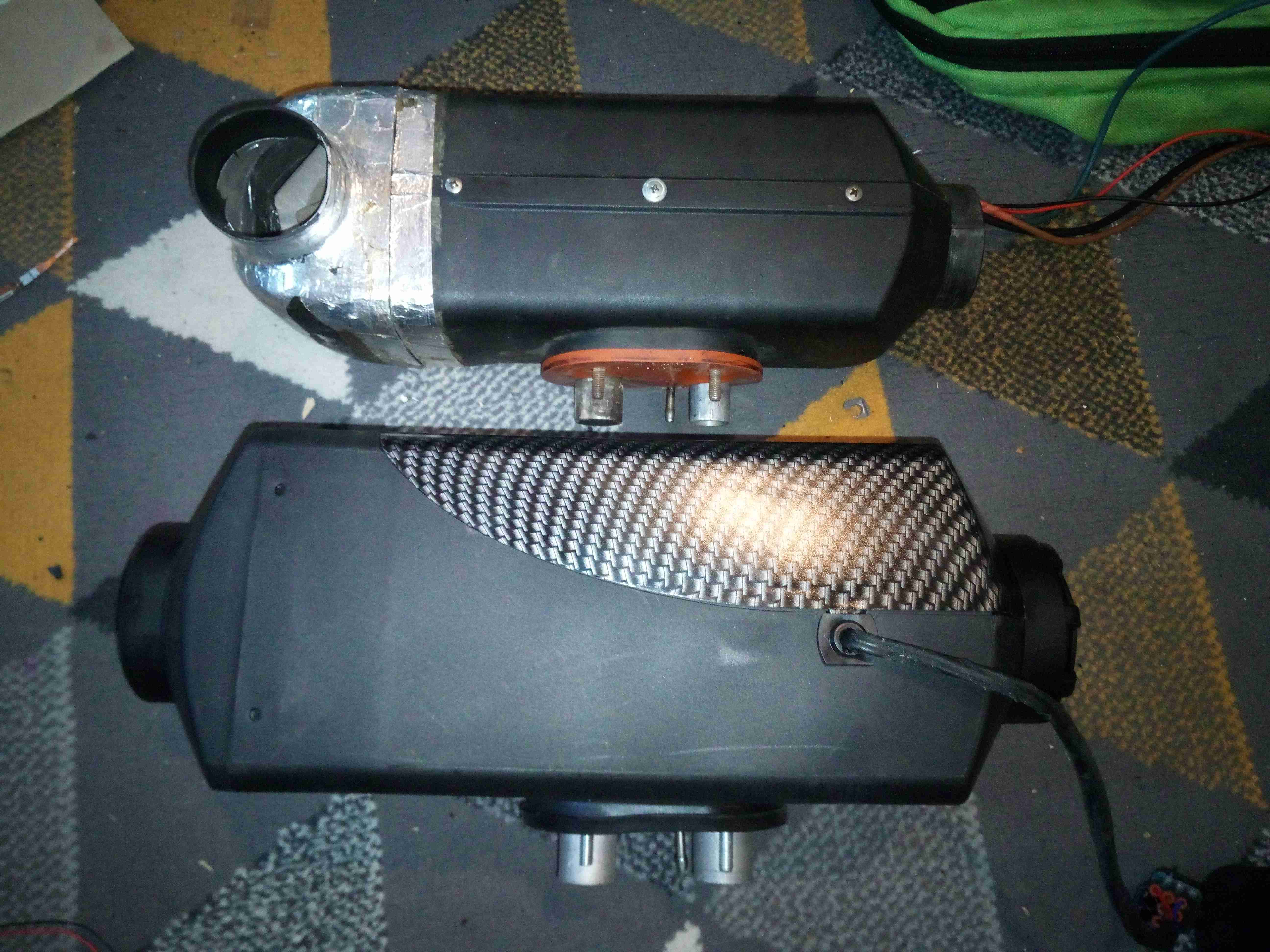
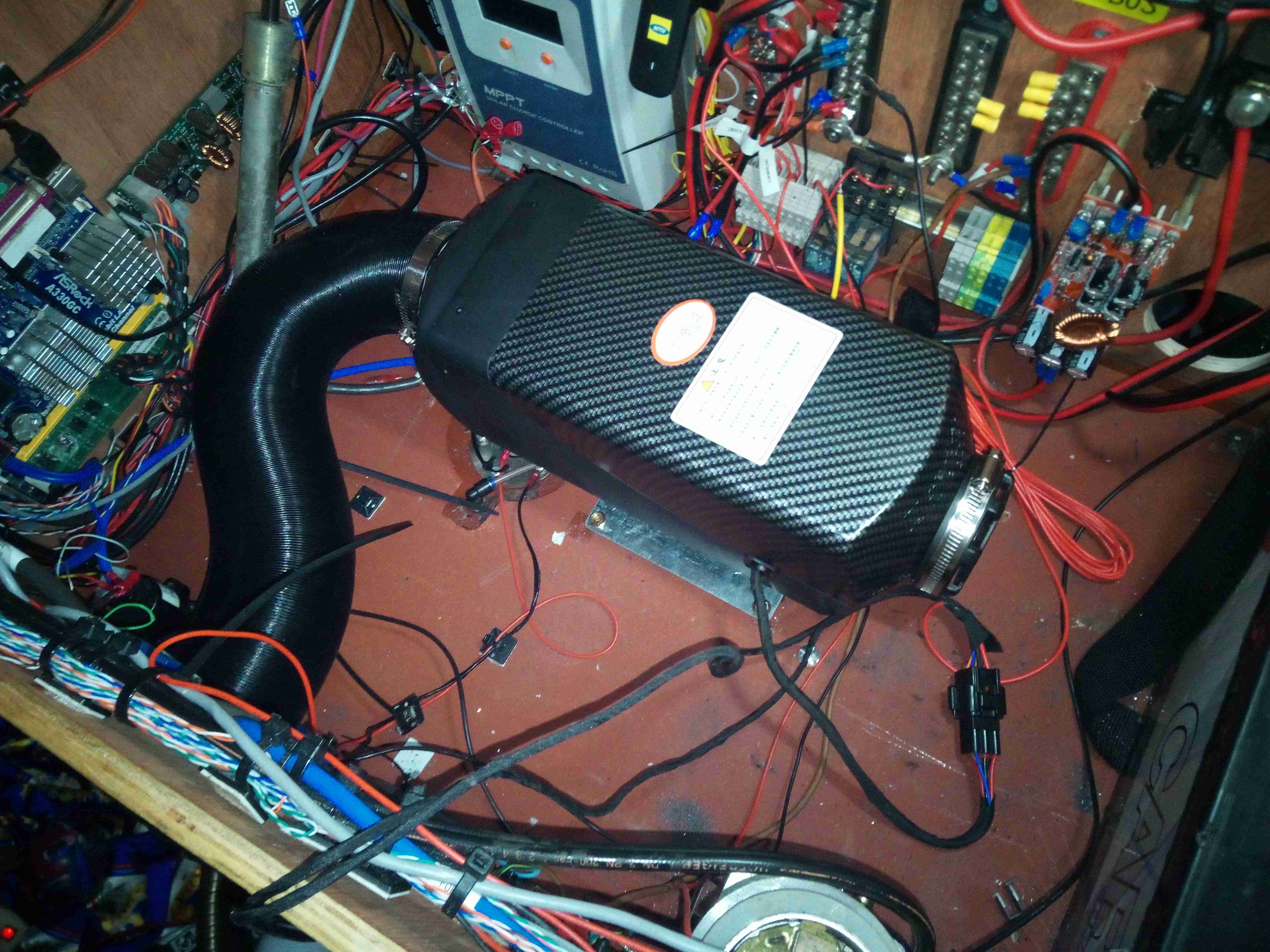
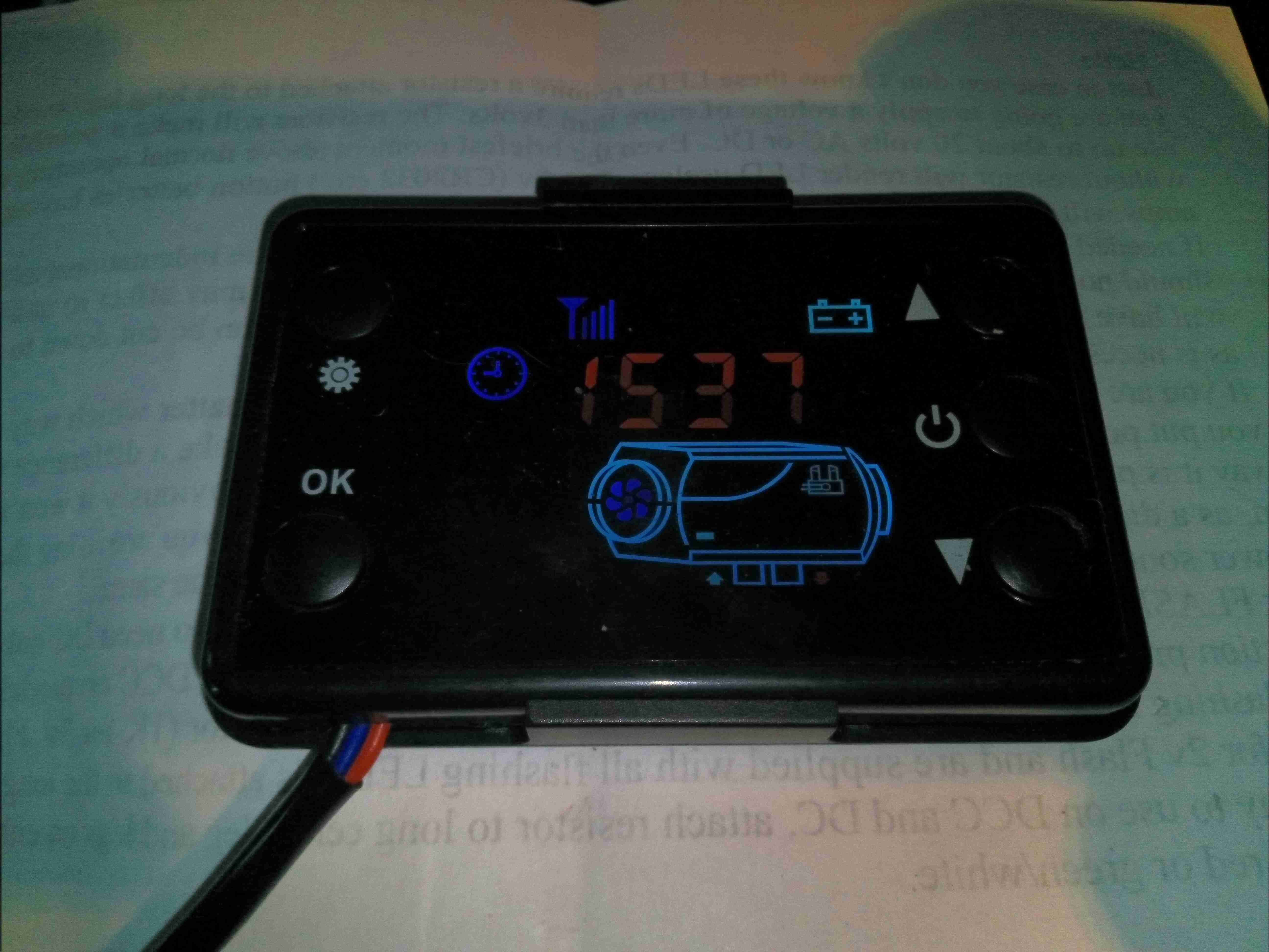
While I’m pretty happy with the Chinese diesel heater replacement for the old Eberspacher on the trolley, the stock controller leaves much to be desired. While functional, it’s fairly unresponsive, bulky & doesn’t allow external control as the Eberspacher did with it’s simple ON/OFF signal. So after a massive amount of searching on the web, (it wasn’t easy to find, damn SEO!), I discovered a project by a chap in Australia who has reverse engineered the communications protocol of these heaters, & built a fully custom controller. This is based around the ESP32 Wi-Fi microcontroller, and a Bluetooth HC-05 module. Display is by means of a 1.3″ OLED screen.
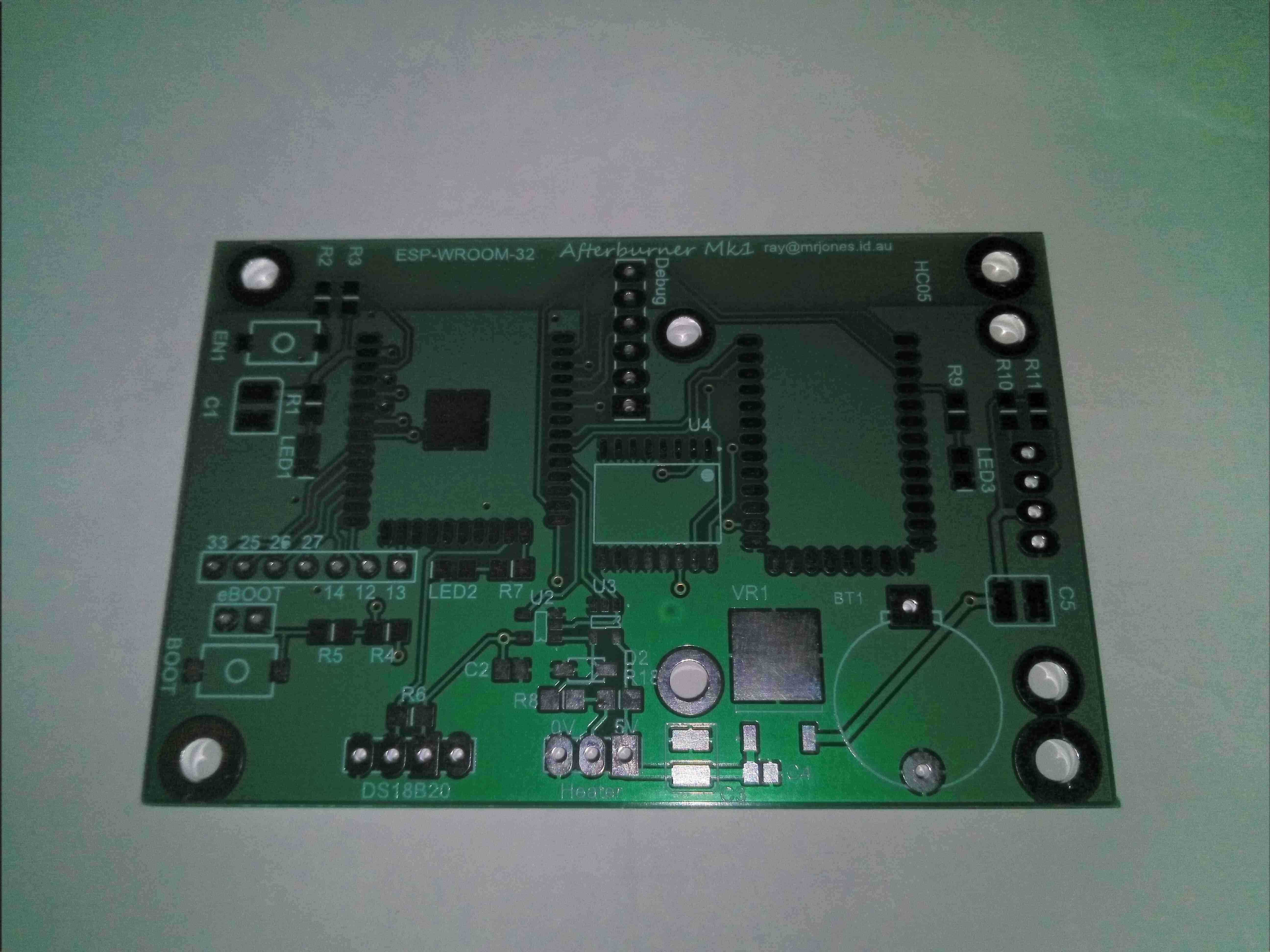
Here’s the bare PCB kindly sent to me by Ray down under to get this project kickstarted. No THT components here apart from headers, everything is minimum 0805 size.
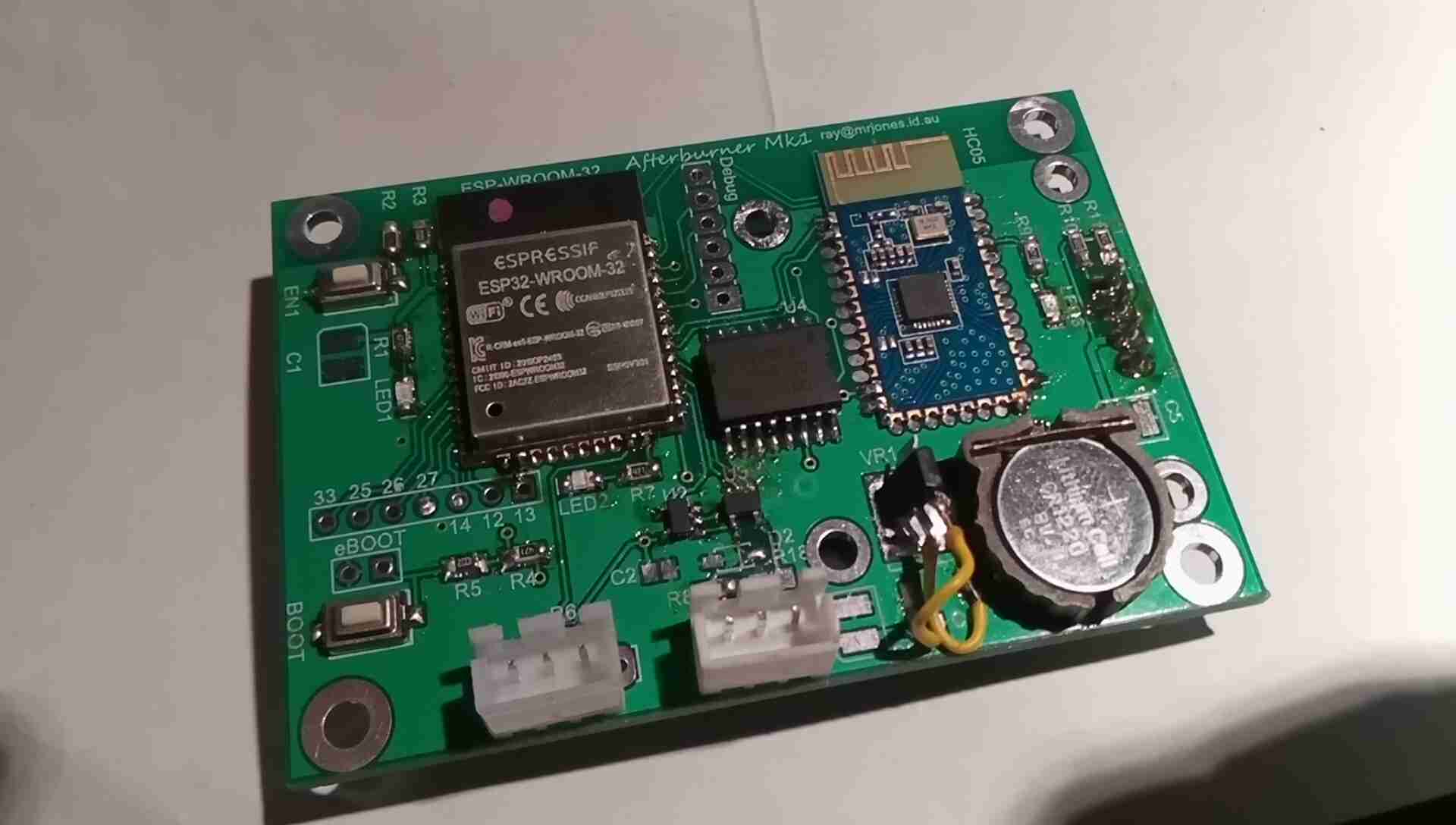
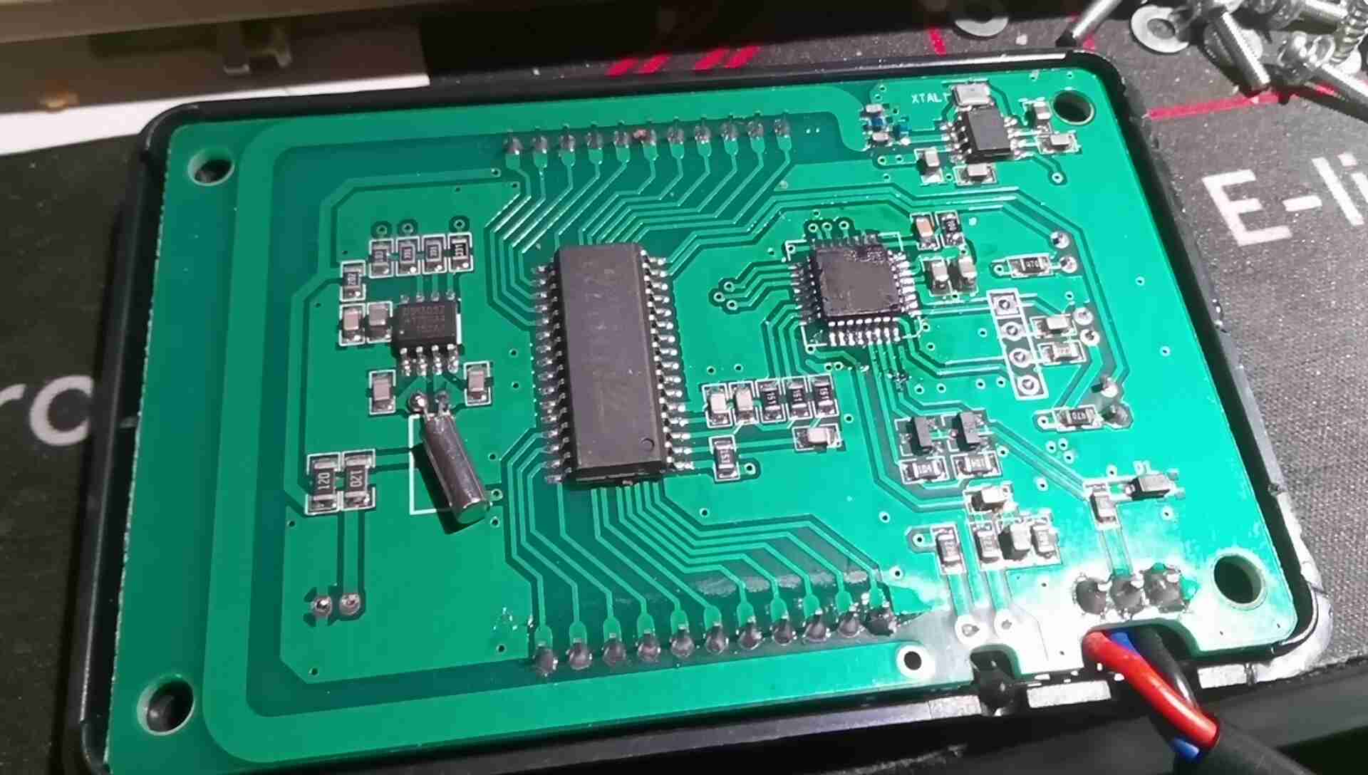
Here’s the controller PCB fully populated, with the ESP32 & Bluetooth HC-05 modules on board. There was a slight issue with the 3.3v regulator not matching the pinout of the PCB, so some minor bodge work required there, but the current draw of the unit is so low that the regulator doesn’t get warm, even with the heatsink tab floating in mid-air. I’ll hot-snot this down to avoid any vibration issues. Incedentally, soldering the castellated connections of the modules is a real pain – problems with contacts not wetting first time were an issue here. Use plenty of flux!
The two JST connectors are for the main heater loom, and an external temperature probe that feeds back for the thermostat mode of the controller. Reset & Bootloader buttons are provided on the board for easy firmware loading. There’s also some spare GPIO broken out for other uses, along with the required UART port for firmware & debugging access. The clock is maintained by a DS3231 RTC IC, which oddly enough is expensive on it’s own – buying an Arduino RTC module & using a hot-air pencil to desolder the IC worked out £4 cheaper than buying the IC direct! The RTC is backed up by a lithium coin cell.
The communications interface is taken care of by a couple of single gates in SOT-23 packages, which interfaces the 3v3 ESP32 with the 5v signalling levels of the heater’s control bus. This unit is a little odd for a communications interface – it is standard serial, but at an odd baud rate of 25,000, and instead of separate TX & RX lines, the transmissions are gated for TX & RX down a single wire. I fail to understand the logic of doing this, since wire isn’t expensive & extra components just add complexity!
A couple of build notes on this controller:
- R4 & R5 are swapped on the silkscreen. Bootloader issues ensued!
- The blue PCB Bluetooth module doesn’t function correctly with the controller, allowing receive but no transmit. Odd.
- There are two pinout variations on the 1.3″ OLEDs. This layout requires the GND pin leftmost.
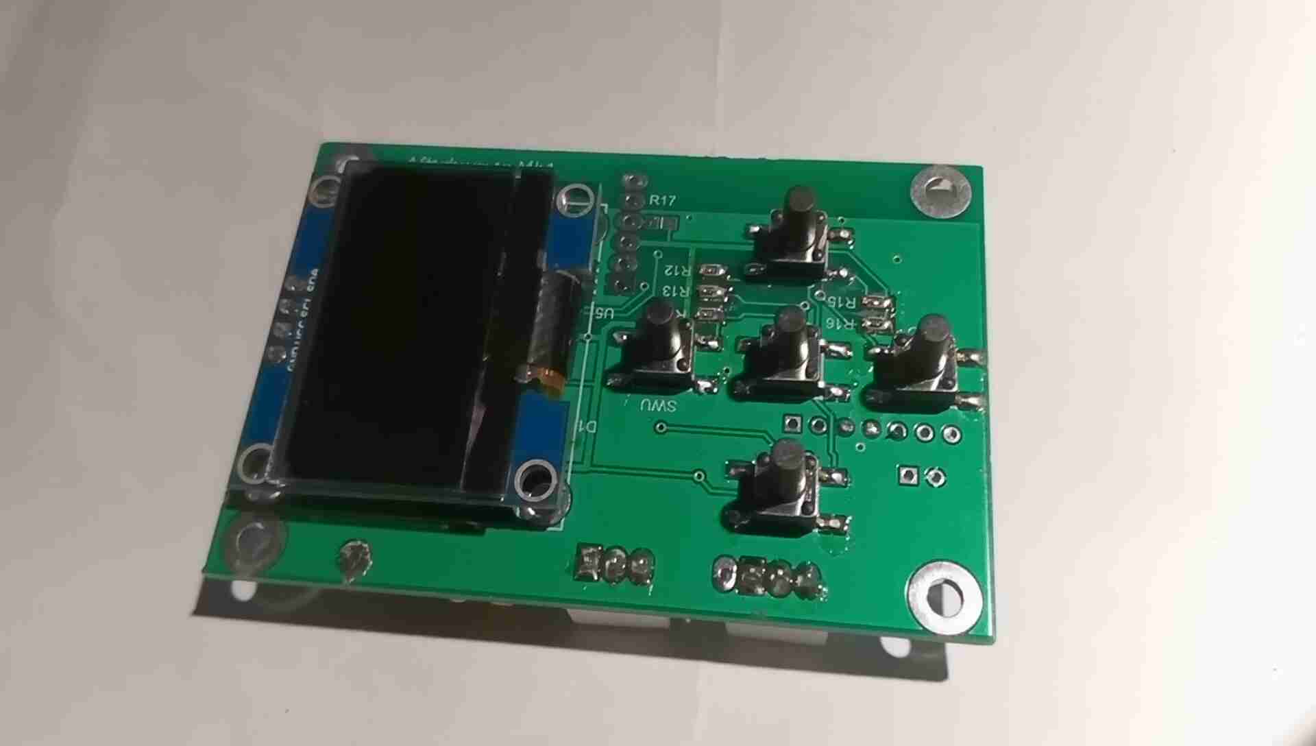
The front of the PCB holds the OLED display panel, and the control button array. Not much else on this side of the board besides the RTC battery switching diodes & some passives.

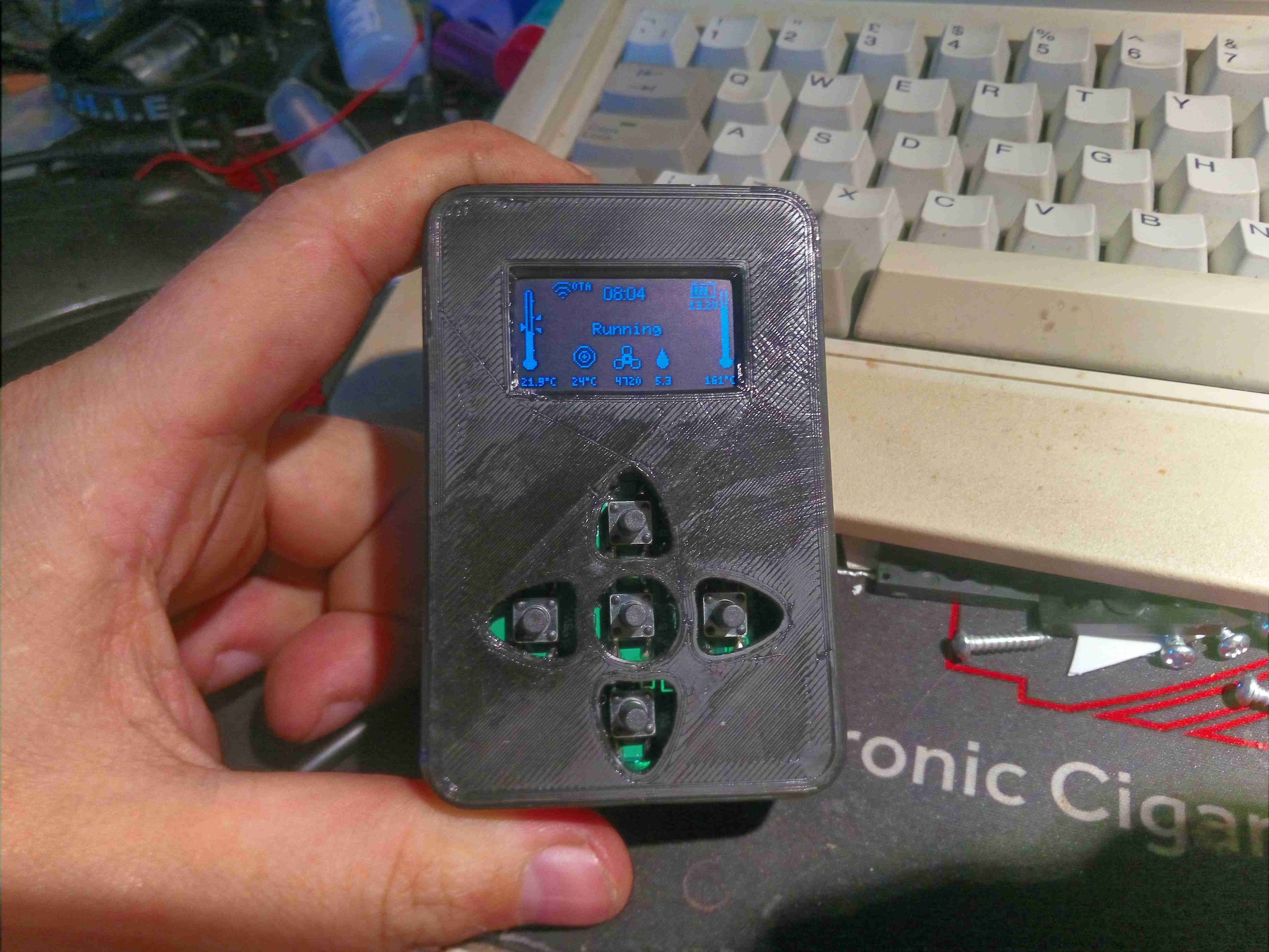
The case to house the PCB is 3D printed, I didn’t bother with the matching buttons as I don’t currently have any flexible filament to print with, so long stem tact switches are used. The controller is running the heater through a cycle here on the Detailed Info screen, where the most comprehensive heater info is displayed. In this stage, the heater’s ECU is warming the glow plug up ready for ignition.
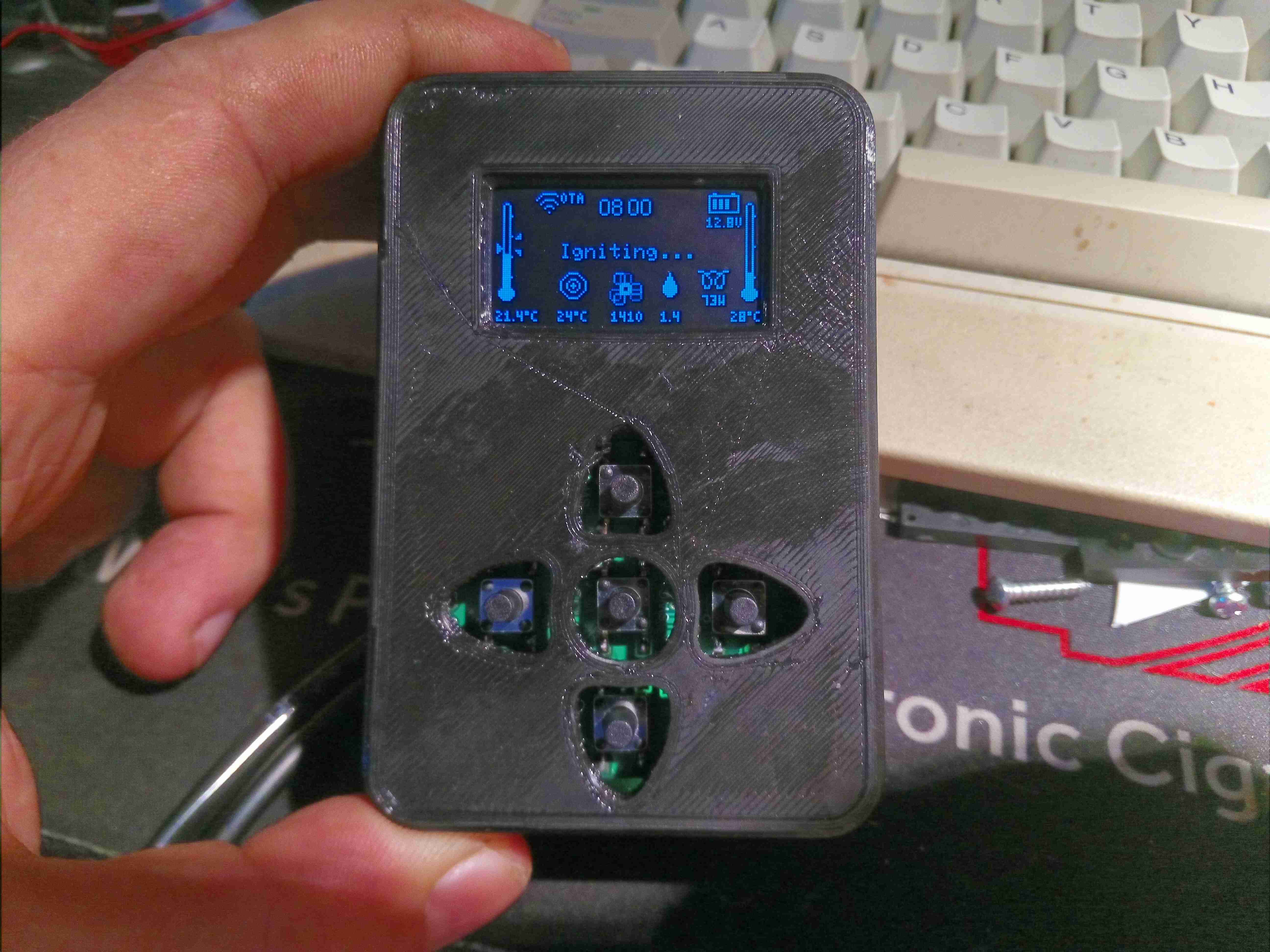
After the glow plug has heated, the ECU starts the fuel metering pump at it’s lowest rate to get a flame going. The glow plug is still active to vaporise the fuel.
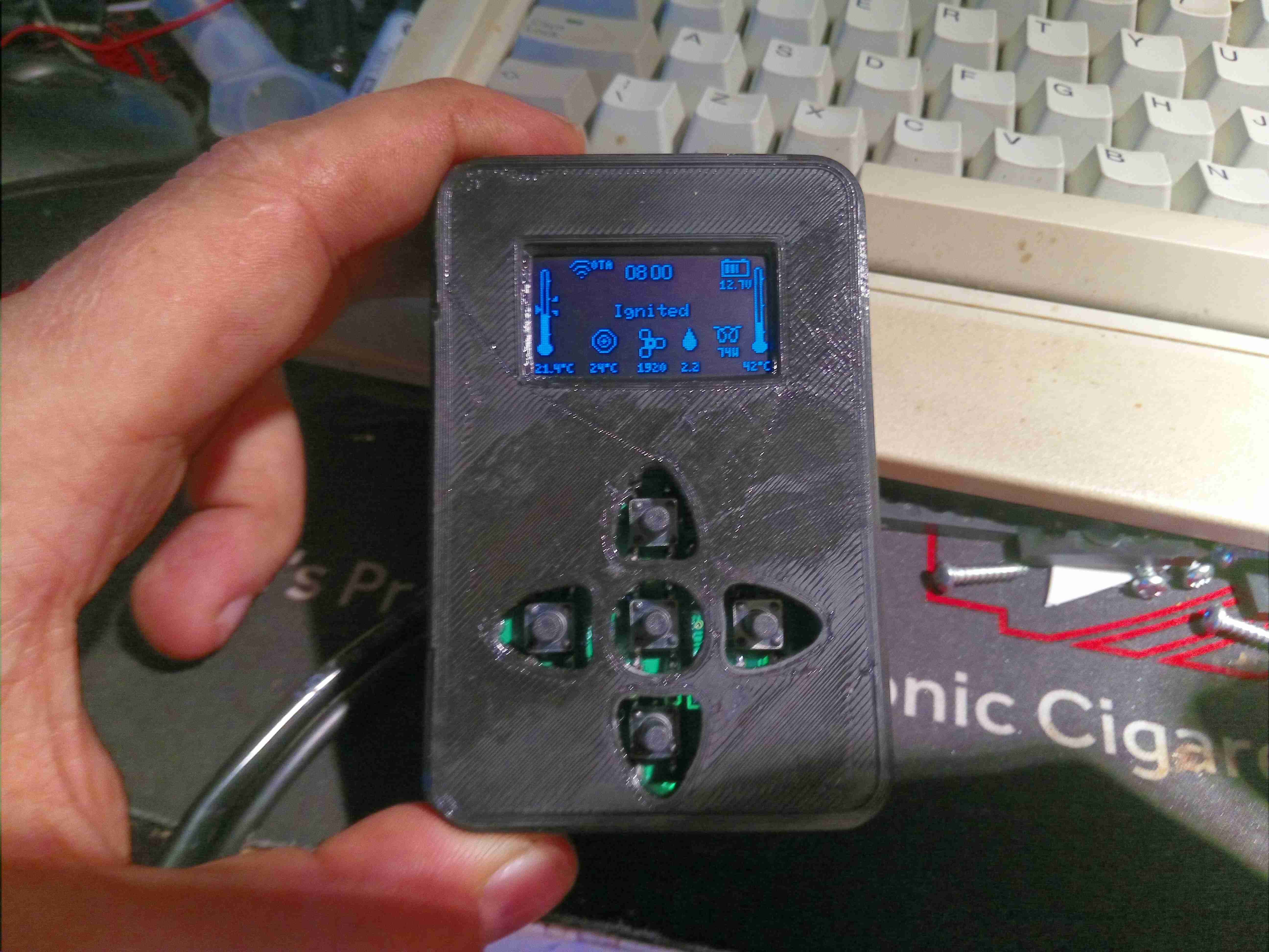
Once the thermistor on the heat exchanger registers a temperature increase, the ECU detects the burner has lit, and starts increasing the fuelling rate & blower speed.
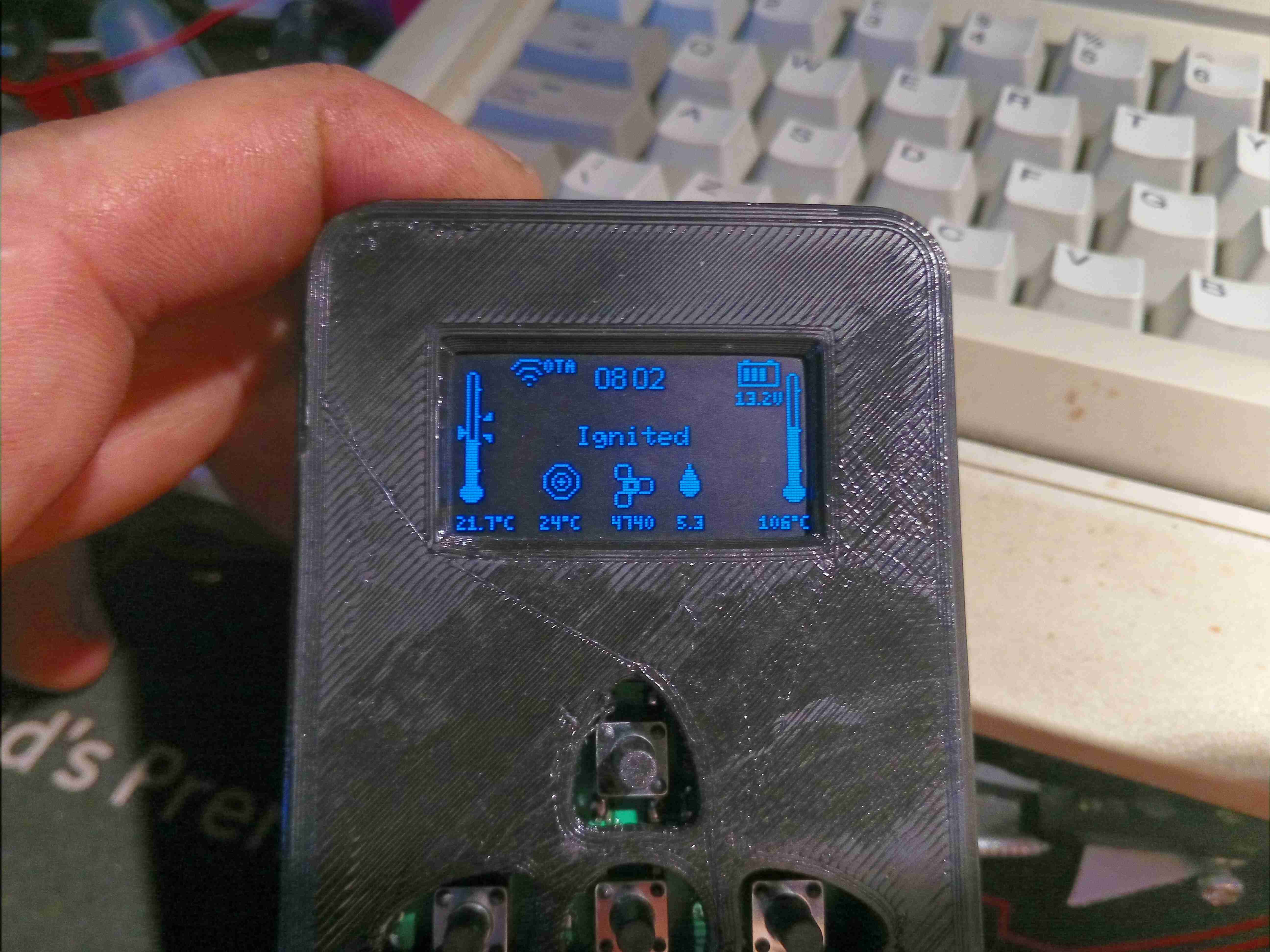
Once the temperature hits a threshold, around 55°C, the ECU switches off the glow plug & ramps the fuelling rate up to max to warm the heat exchanger to operating temperature. The detailed page displays both the room temperature (left), set temperature & heat exchanger temperature (right).
Once the heat exchanger has reached running temperature, the ECU switches control to the thermostat, in this case the new controller.
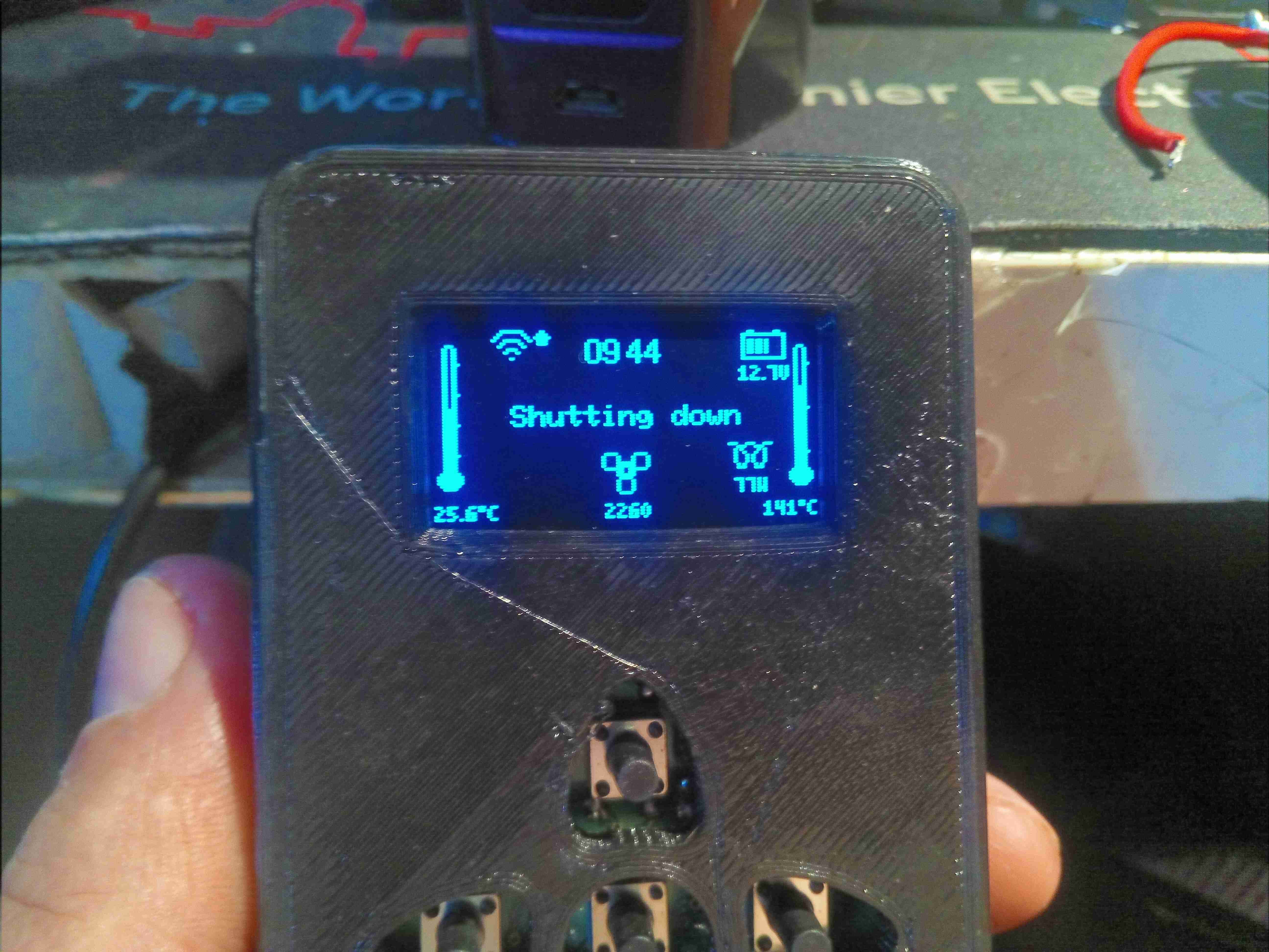
When a shutdown is initiated, the heater brings the glow plug back on & reduces the fuelling rate to minimum for a couple of minutes, before stopping fuel flow. The glow plug remains running for a while to burn off any remaining fuel residue.
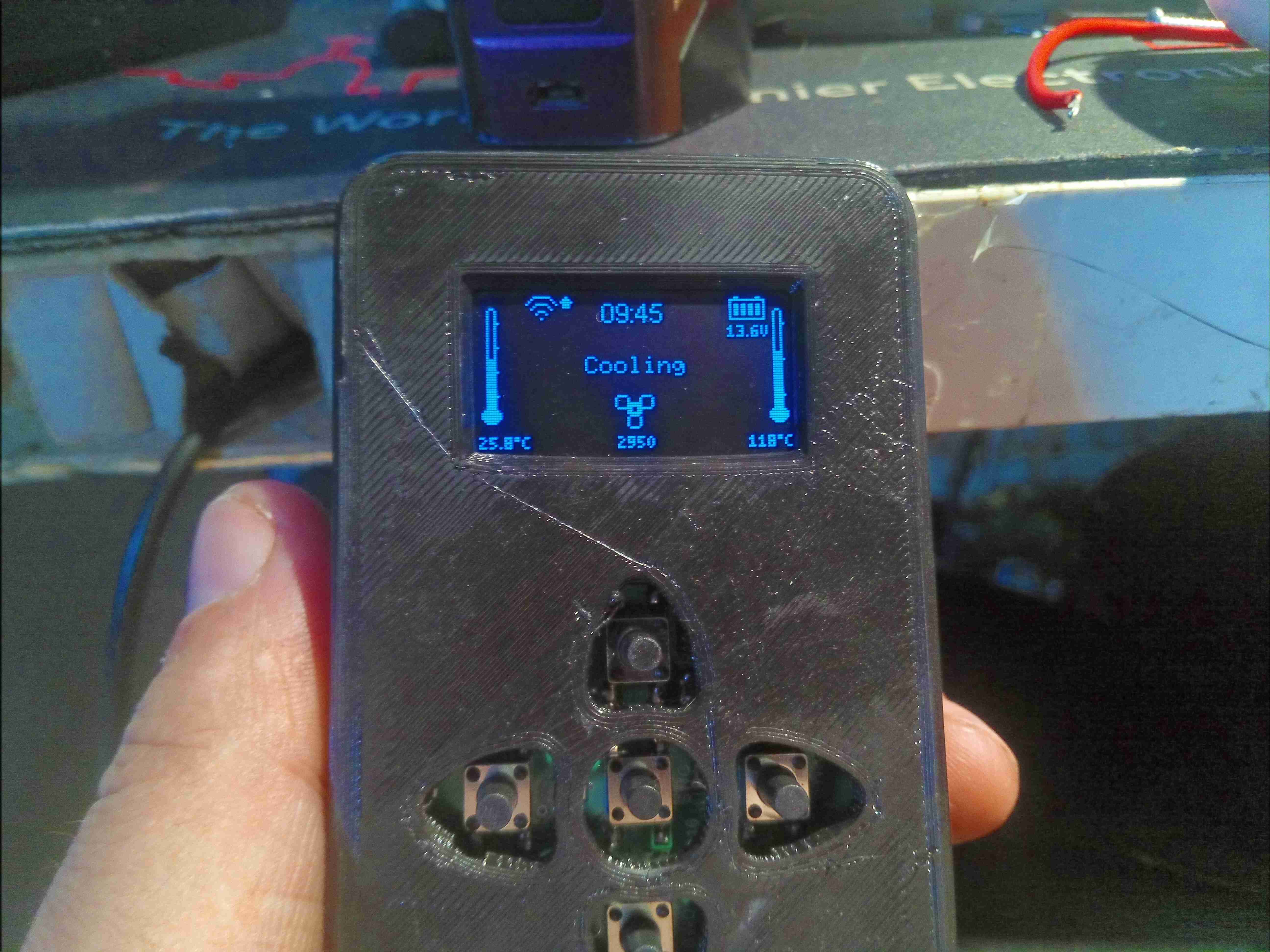
Finally, the ECU cuts power to the glow plug, and keeps the fan running at medium speed until the heat exchanger cools to below 55°C.