While we’re away camping, be it at a festival or general site, it would be nice to have a relatively efficient fridge to store food & drink in, so I set to work assessing the requirements. Commercially supplied 12/24v fridges are hella expensive – running between £450-£700 for even a small compressor coolbox! So in my general style, I figured it was time to get building my own, integrated into the current system. With the bonus of learning some things along the way. There are some refrigerants that aren’t covered under the F-Gas regulations, such as R600a (Isobutane) & R290 (Propane), so I can easily avoid those legal requirements, not to mention being a little more environmentally conscious. The common Danfoss BD35F compressors are designed for R-134a, but there are equivalent replacements available for the automotive AC market that operate within the same pressure ranges. As far as I can tell, these replacements are mixtures of R600a & R290 in various proportions.
I decided to keep most of the weight, control & wiring internal to the main power trolley which goes everywhere with us while camping, this obviously required the refrigerant lineset to be dis-connectable from the fridge cabinet for transport, and has the requirement for a flexible lineset between the two. The marine-grade refrigeration systems destined for custom builds are supplied with dis-connectable copper linesets with special fittings, so I went in search for a supplier of said fittings. The need for flexibility & re-usability means I can’t use the copper lines in this application – work hardening will quickly cause the copper pipe to crack.
Parker-Hannifin supply these special fittings, and seem to be the original manufacturer – considering they specialise in fluid power & control, this isn’t a surprise. However ordering from them is a nightmare, so no go there. I did find an Italian supplier of equivalent fittings, the Faster Coupling RF series:
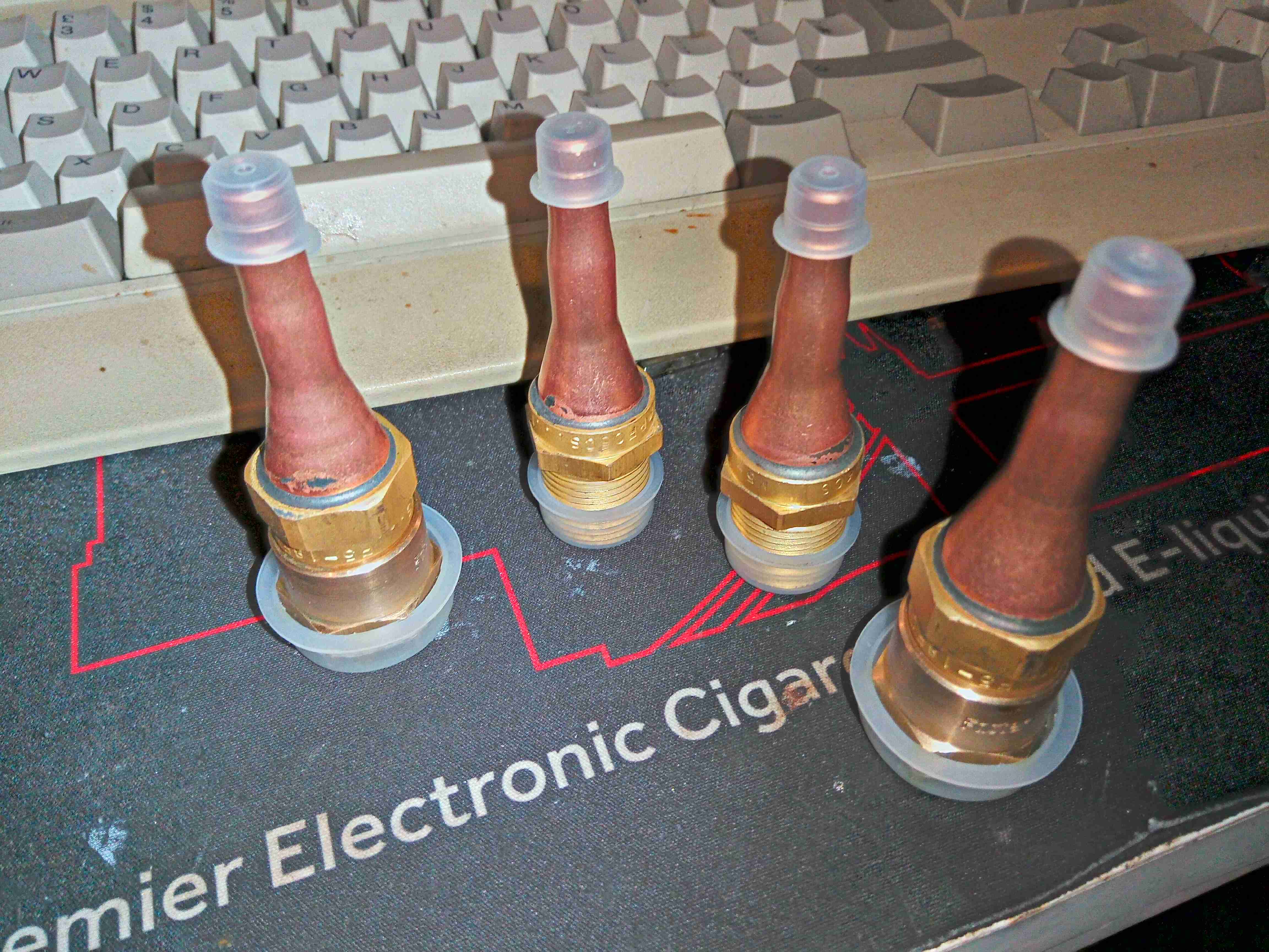
Luckily, I was able to get a distributor in the UK to order these in for me, but they are a bit expensive, at ~£130 for two pairs. I sized these for 1/4″ to match the compressor lines. They’re quite well made from brass, with copper tails silver-soldered for braze connections.
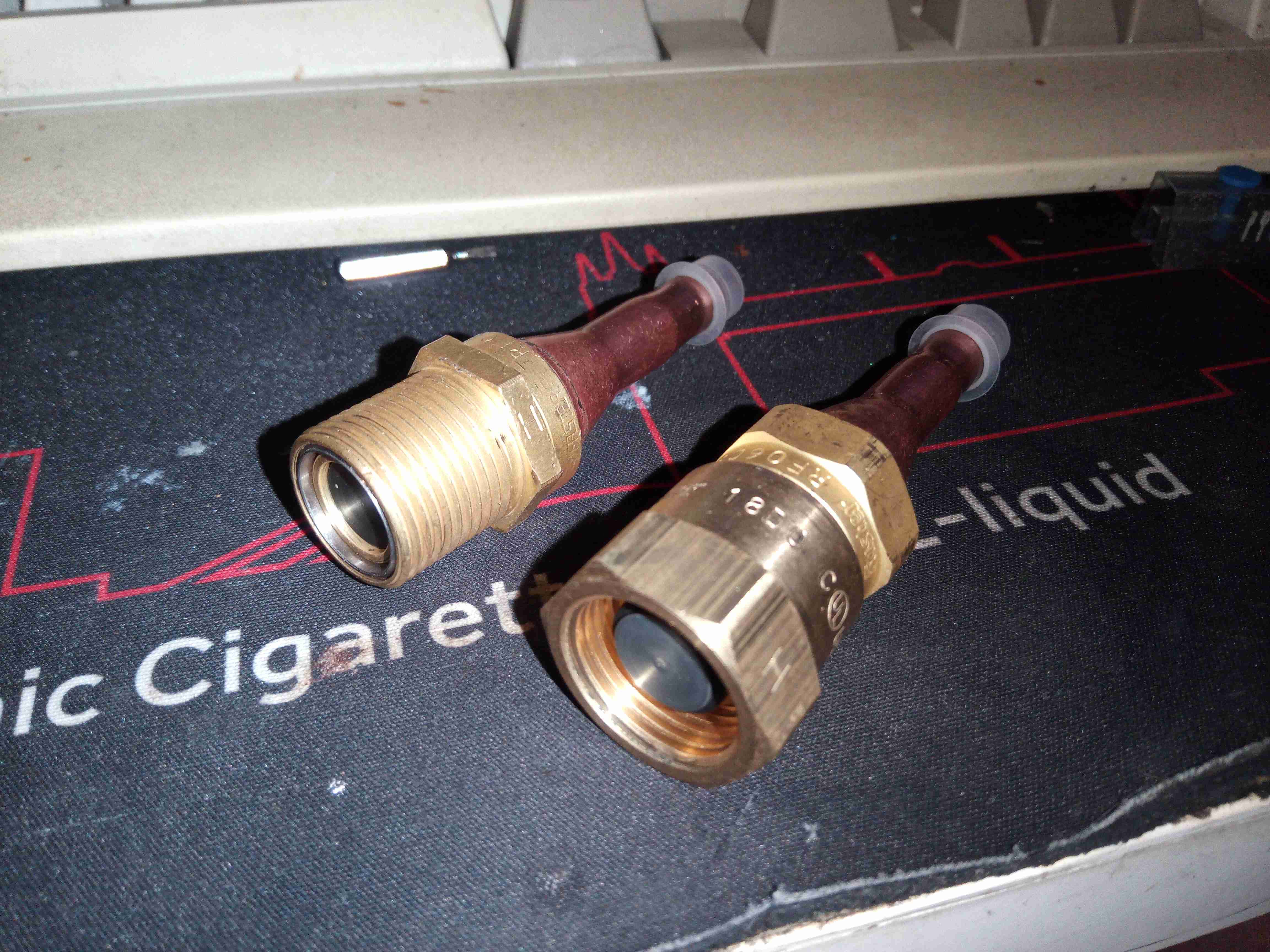
The fittings screw together like hydraulic couplings, however these are designed for very low leakage, and very low admission of air when connecting them together.
Time to get these panel mounted on the back of the power trolley. The 1/2″ plywood frame is too thick to mount these directly, so I had to improvise a mounting plate:
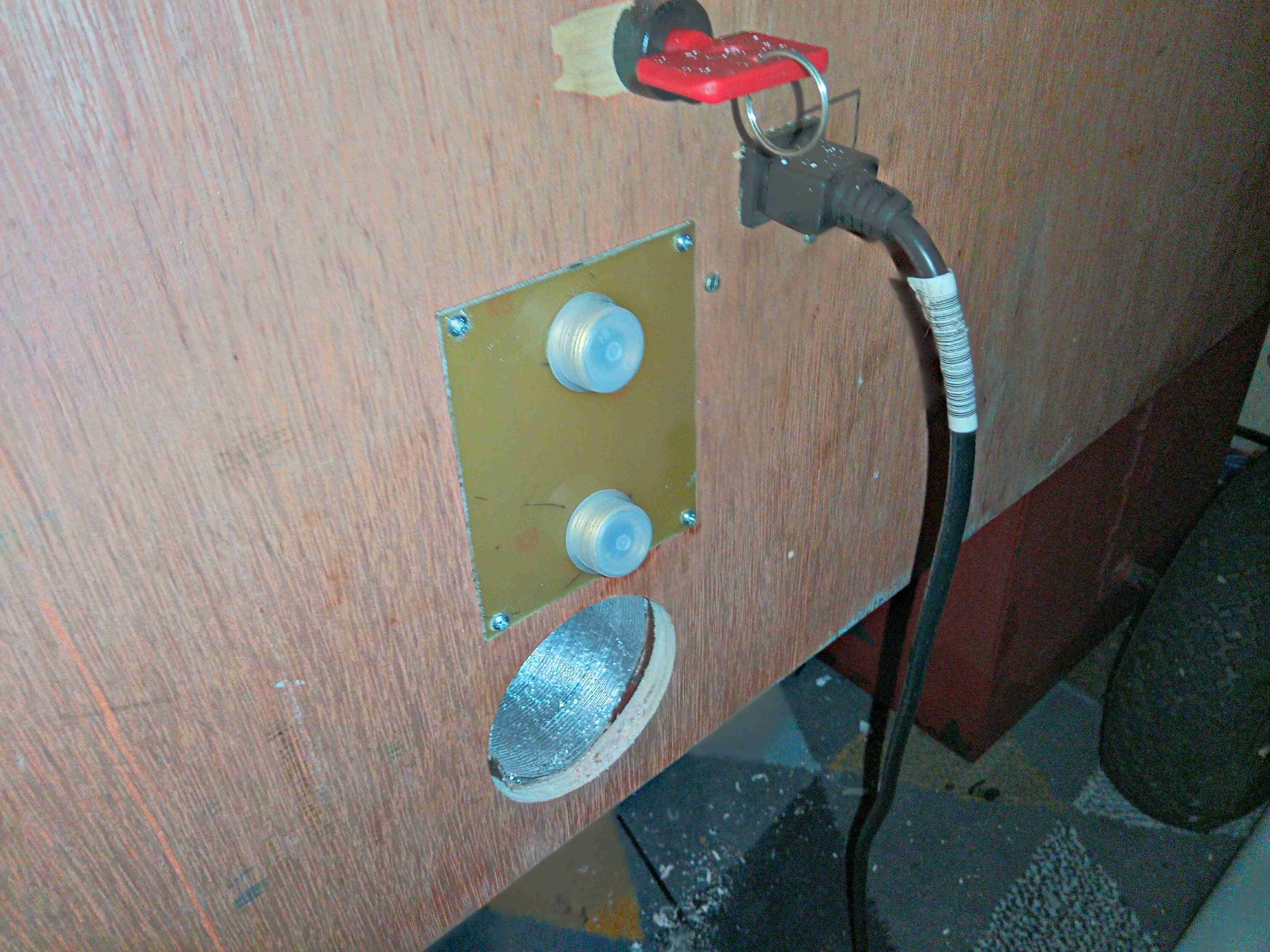
A bit of FR4 PCB material with suitable holes bored makes for a nice thin panel with high strength. I will colour-code these to make sure the suction & discharge lines aren’t mixed up when connecting, considering they’re both the same size.
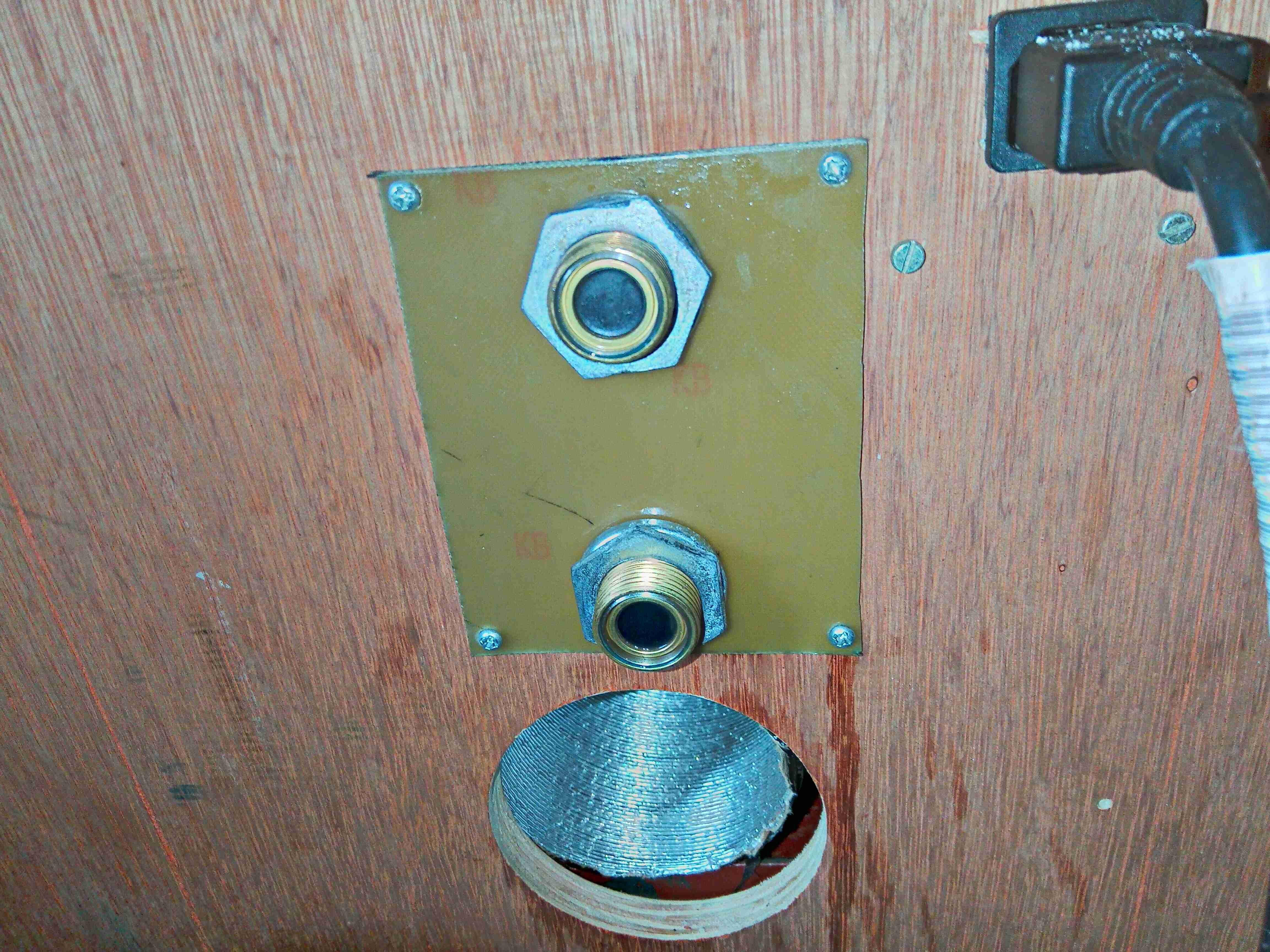
The fittings are secured with M20 conduit nuts & spring washers.
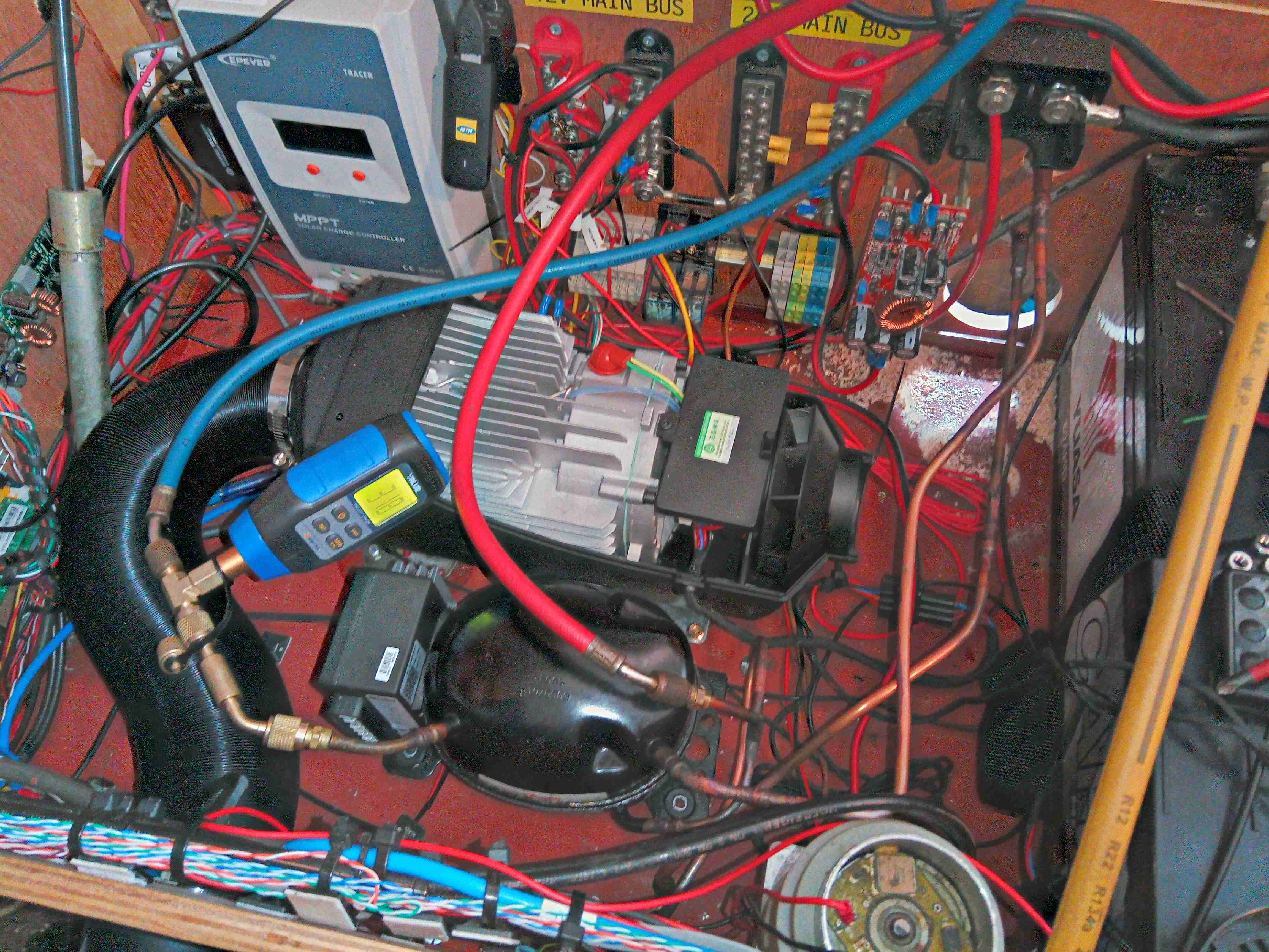
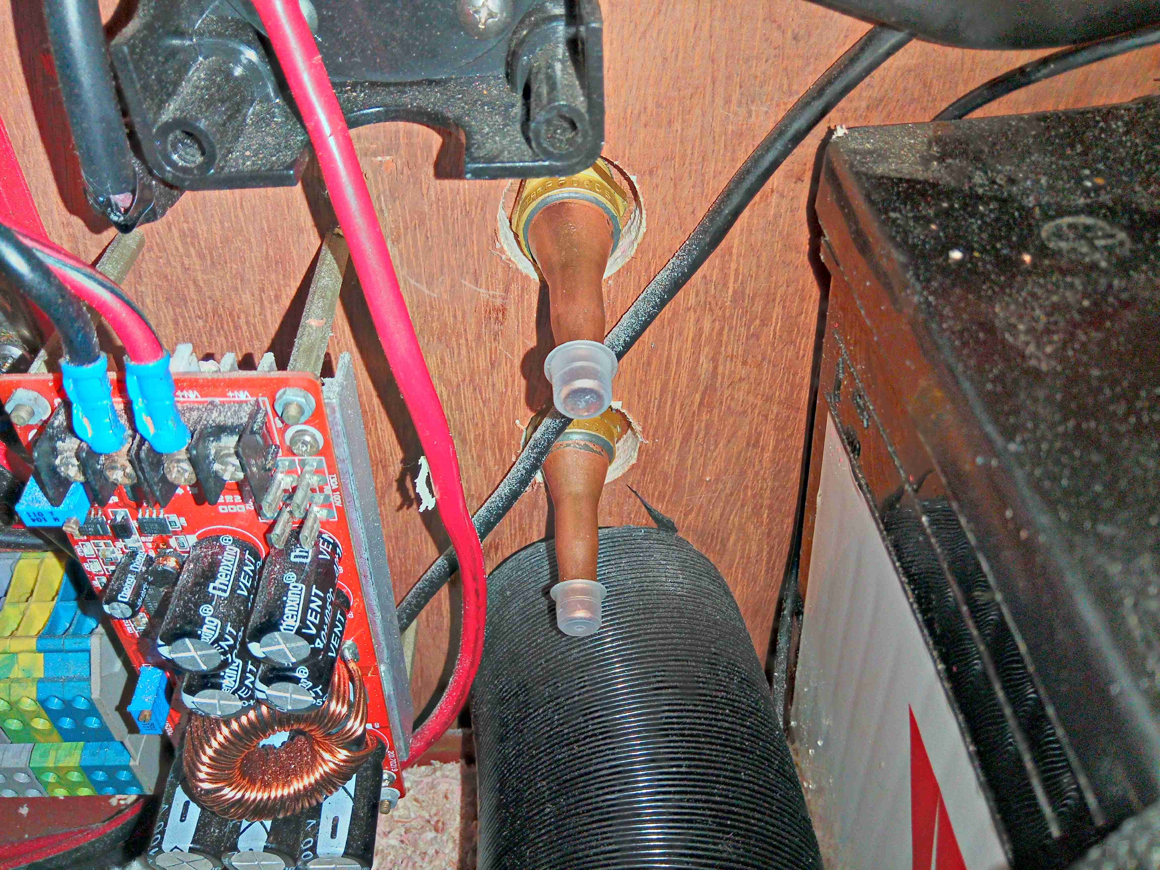
Here I’ve got the compressor fitted & all the lines brazed, and have the system under vacuum to get any traces of water out. Side note: the RF series couplings are *very* difficult to braze with just a single burner MAPP torch – keeping the end of the fitting with the rubber seals submerged in water to stop them melting just conducts too much heat away from the copper tail too quickly. I did successfully manage to get them brazed though, and this section of the system holds both vacuum & pressure to 12 bar. The condenser coil is mounted underneath next to the fuel tank:
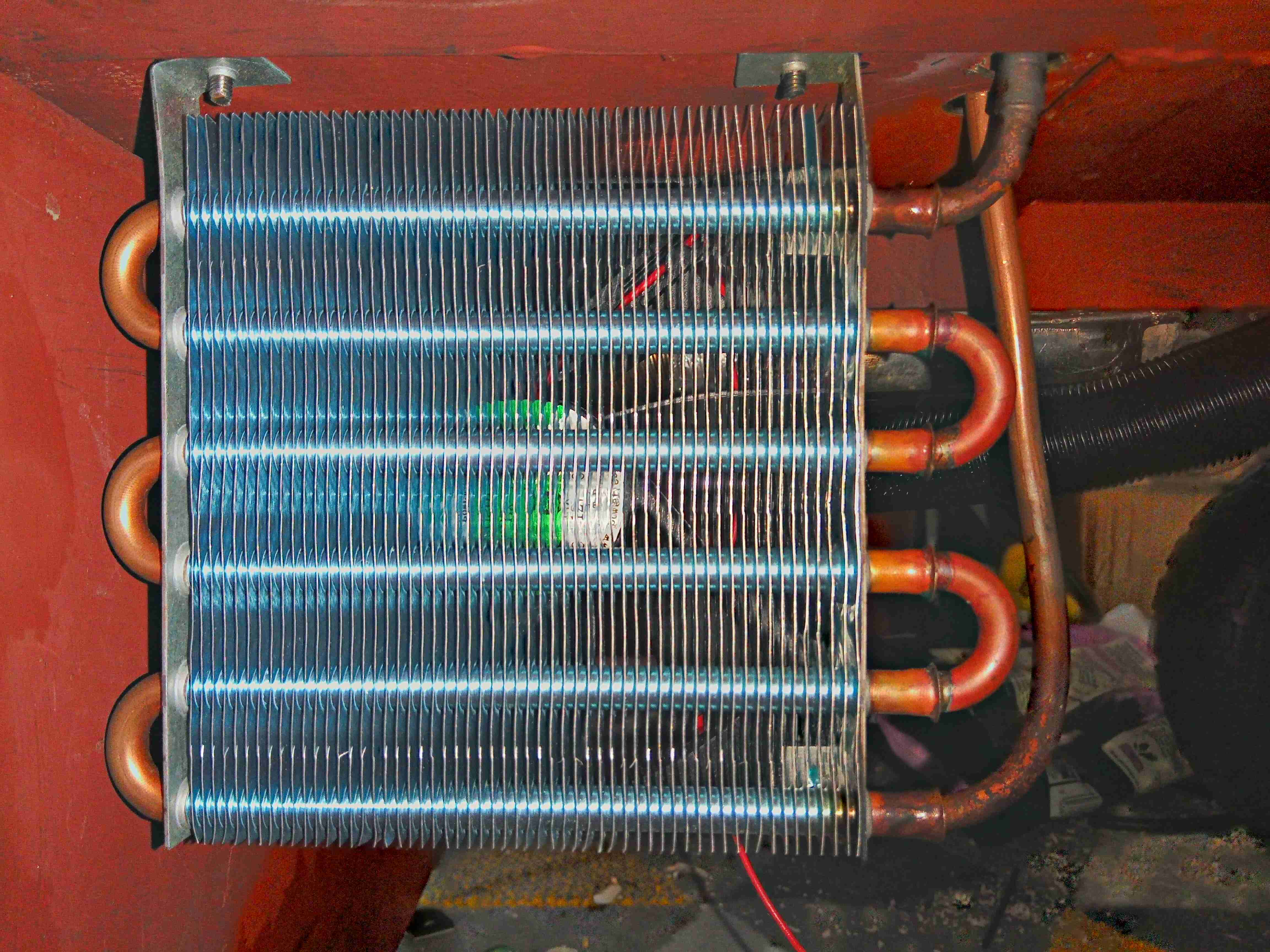
There’s a 120mm fan behind for forced air cooling, with the refrigerant lines run up to the compressor above.
I’ll be back soon with the build of the fridge cabinet & evaporator section!