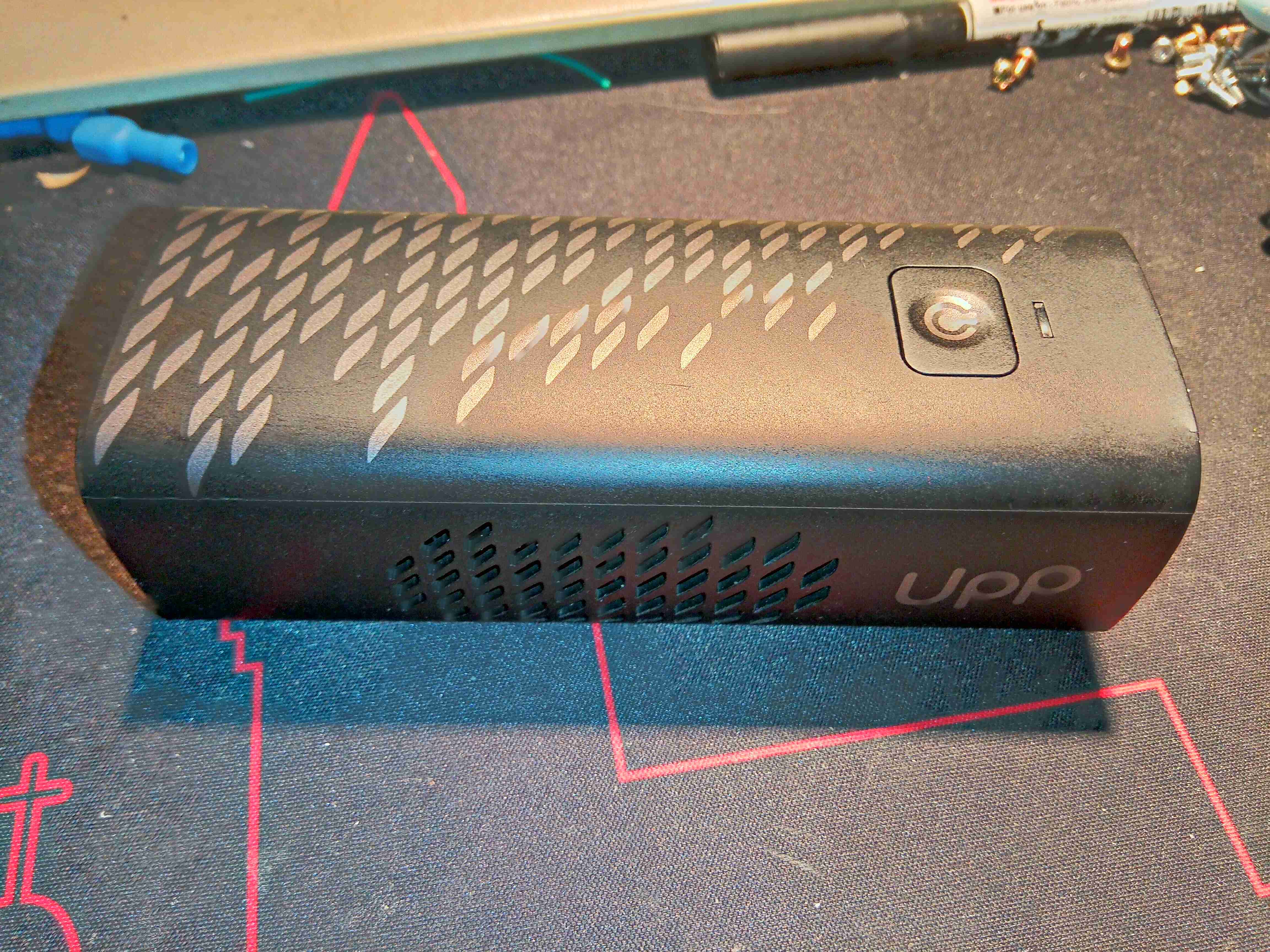
After watching Mike’s Electric Stuff’s video on these a while back, I figured it was time to grab one from eBay & see for myself how pointless a tech these are. As far as I am aware, these units are no longer available, the domain name redirects to a company site with no mention of them, and getting cartridges refilled might not be possible without some DIY engineering. These are a small portable Hydrogen-powered PEM (Proton Exchange Membrane) Fuel Cell unit, with a USB output port for charging mobile devices. There’s quite a few vents on the sides of this device, as there has to be an airflow through the PEM Fuel Cell itself, and the only control interface is a single button on the front of the unit.
The Hydrogen gas is stored in a cartridge, filled with Hydralloy C5 metal hydride powder. These would be exchanged for a full one when all the gas has been used, at a cost of about £6. (Extra cartridges apparently cost about £50!).
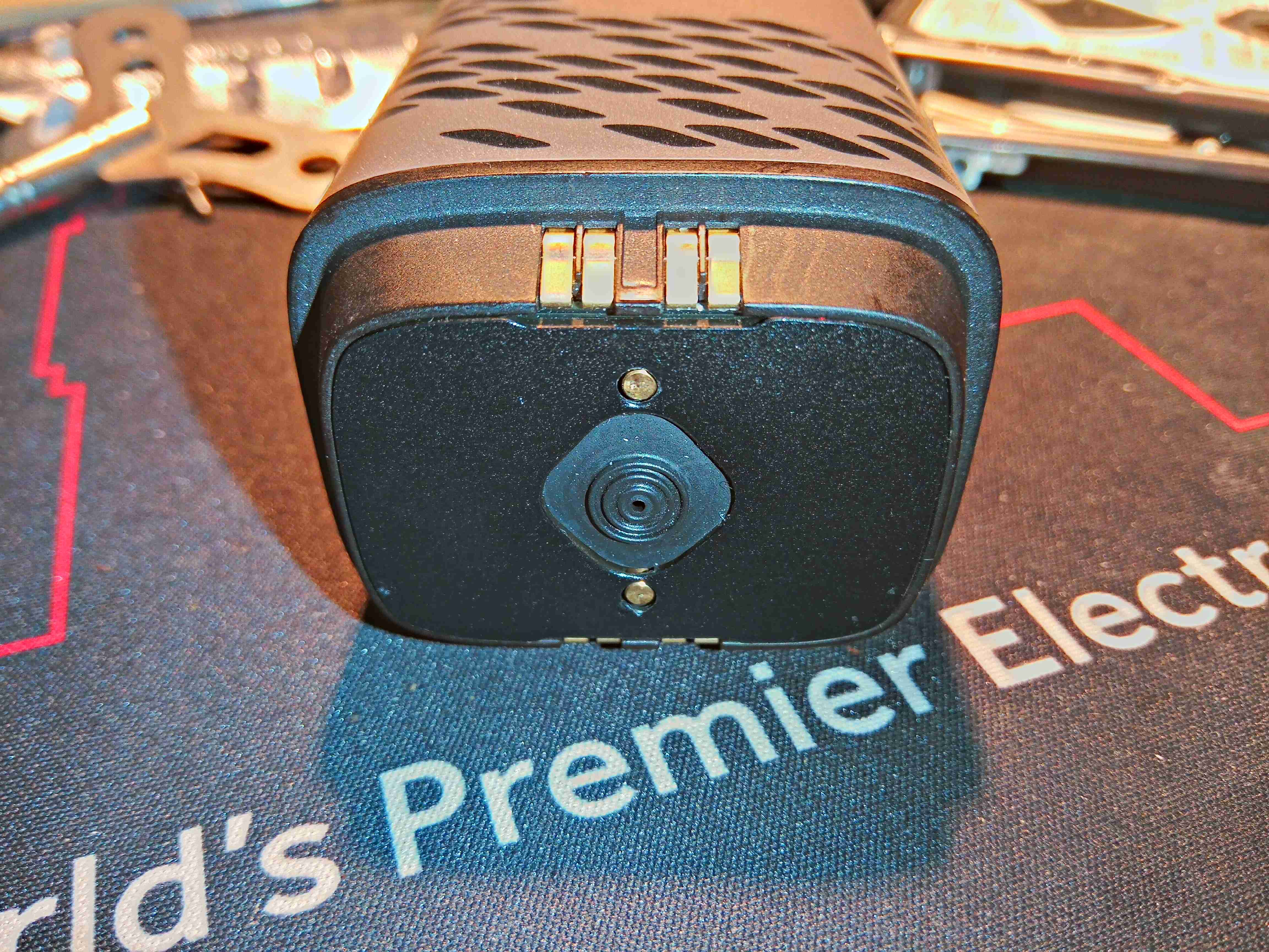
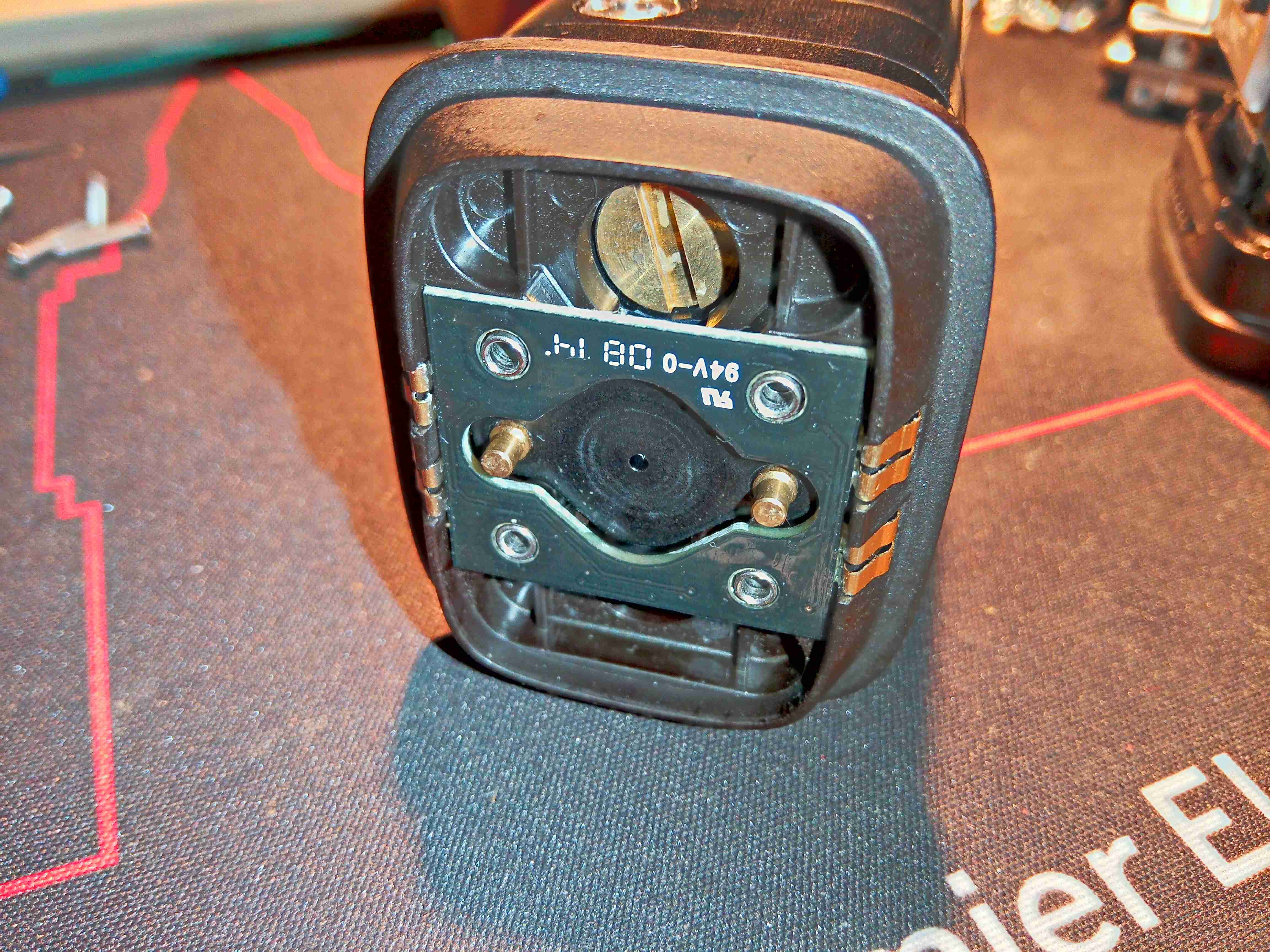
The top of the cartridge holds the main valve, and some contacts. The gas is permitted to flow from the storage hydride by means of the two brass pins on either side of the seal – when these are both pushed down by pins moulded into the bottom of the main fuel cell unit, the internal valve is opened. The contacts connect to an internal PCB with a single EEPROM.
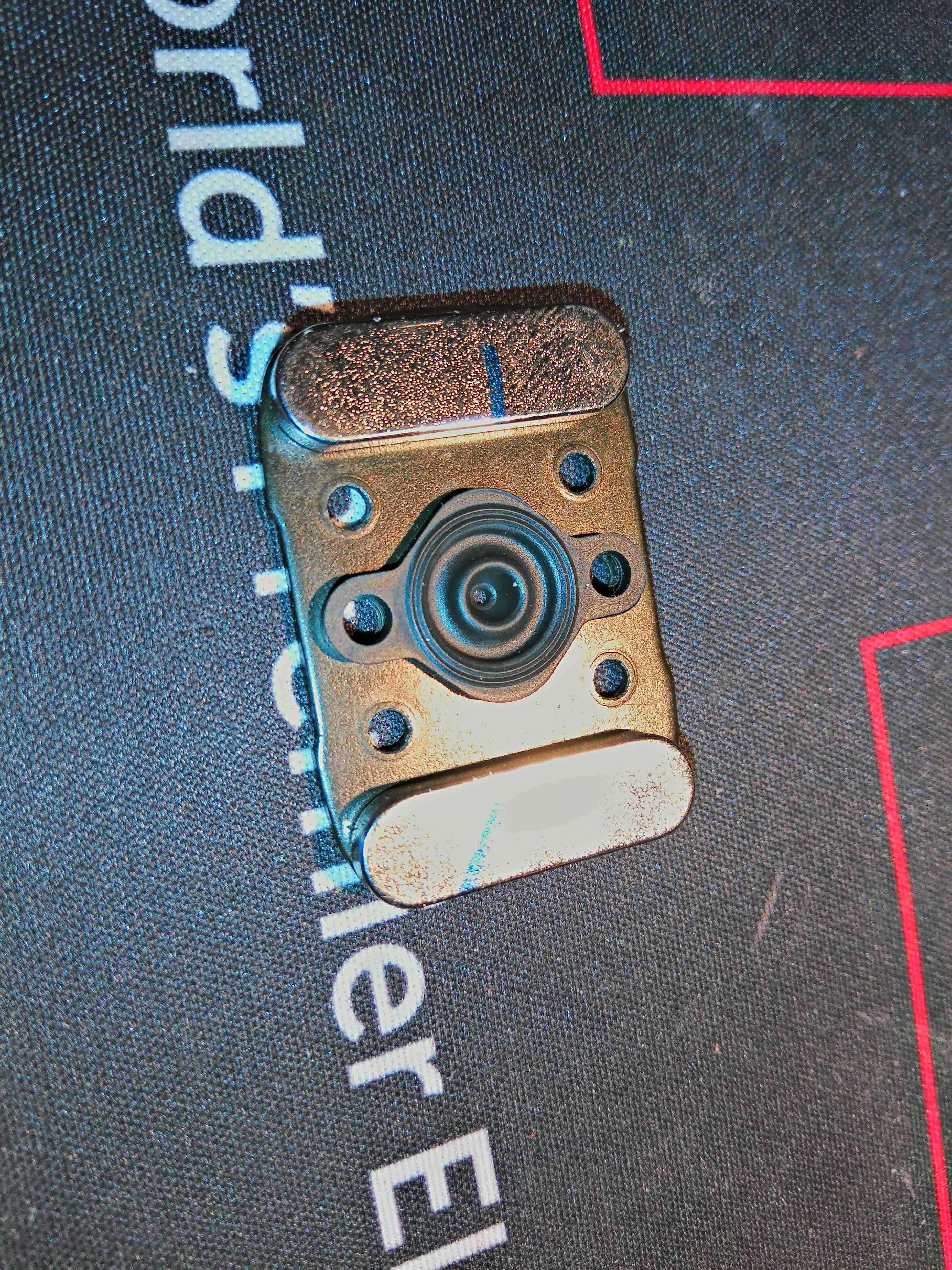
The cartridge is attached to the fuel cell with magnets – there are a pair of very powerful NdFeB magnets behind the main steel plate on the top, and a matching pair inside the bottom of the fuel cell assembly.
Removing a label allows access to 4 screws, which hold the top assembly onto the pressure vessel section of the gas cartridge. Here is the internal PCB with it’s EEPROM, and the large brass screw which may be for regulating the gas flow rate.

Removing the PCB allows us to see the EEPROM itself – a 2kBit part, which contains information like remaining gas charge, and serial number. When the cartridge reads empty according to this EEPROM, the cell will stop functioning. Luckily however, it is happy to operate without this PCB even being present – I expected the unit to spit & error & shut down if it couldn’t communicate over the I²C bus with this memory.
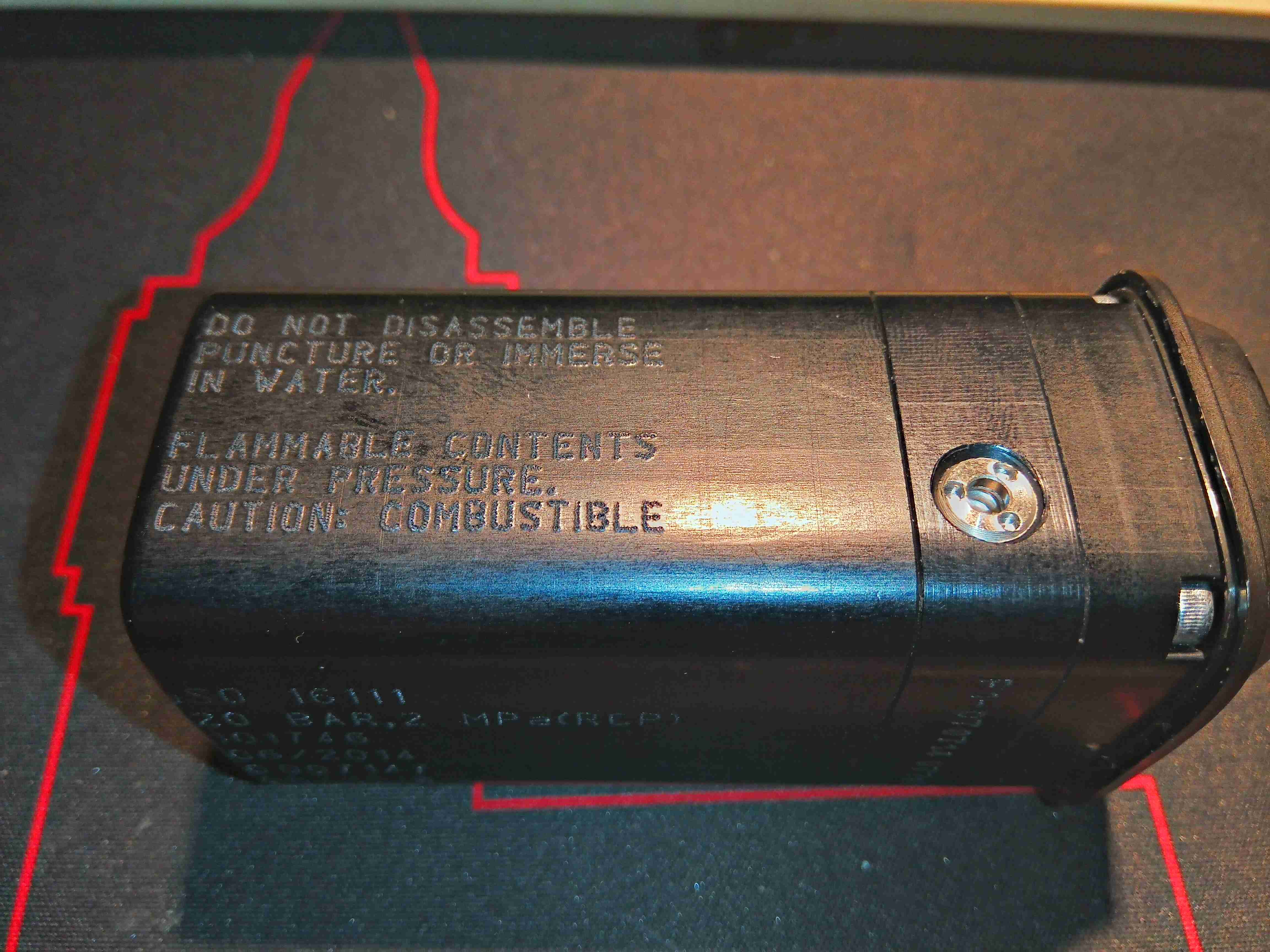
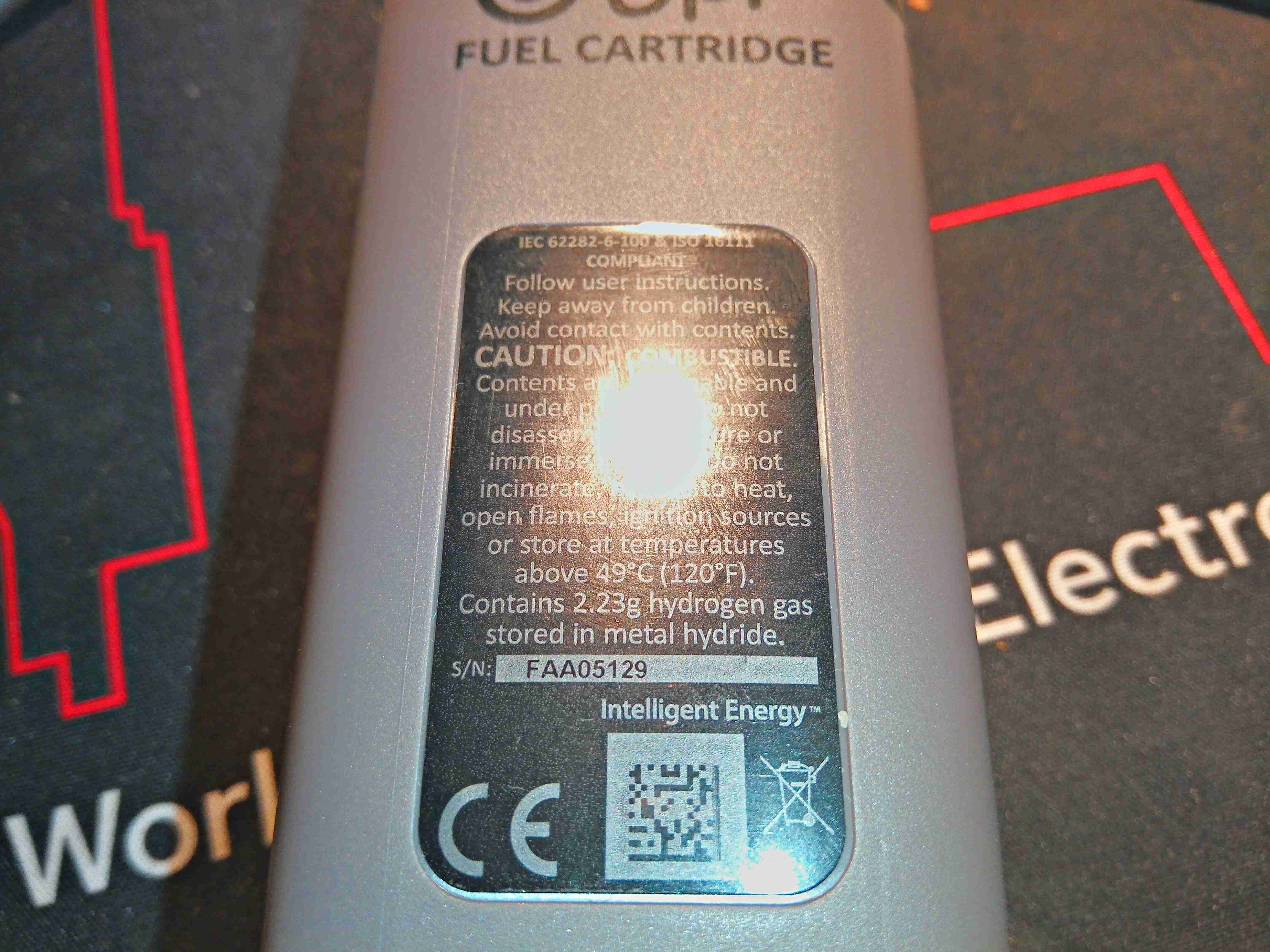
Removing a screw in the base of the casing (hidden under a label) allows the plastic shell to come off, revealing the aluminium pressure containment to be seen. There’s a pressure relief valve on the side here, and some warnings about what not to do with the thing.
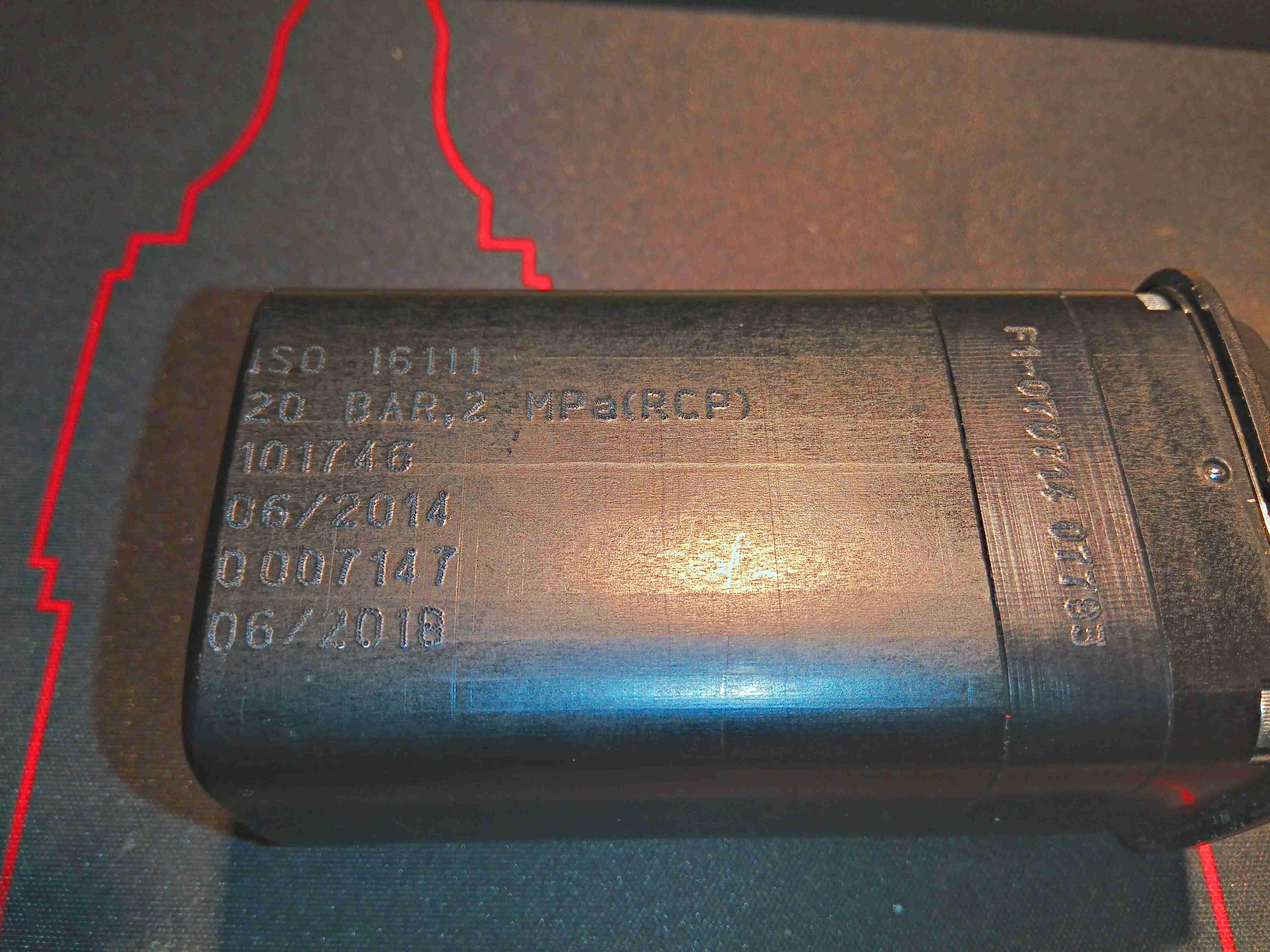
Some more info on the other side, with the ISO standard this cell is rated to, and the 20 bar Rated Charging Pressure. There is also a stamp indicating how long the certification of the vessel lasts. This one is rather out of date…
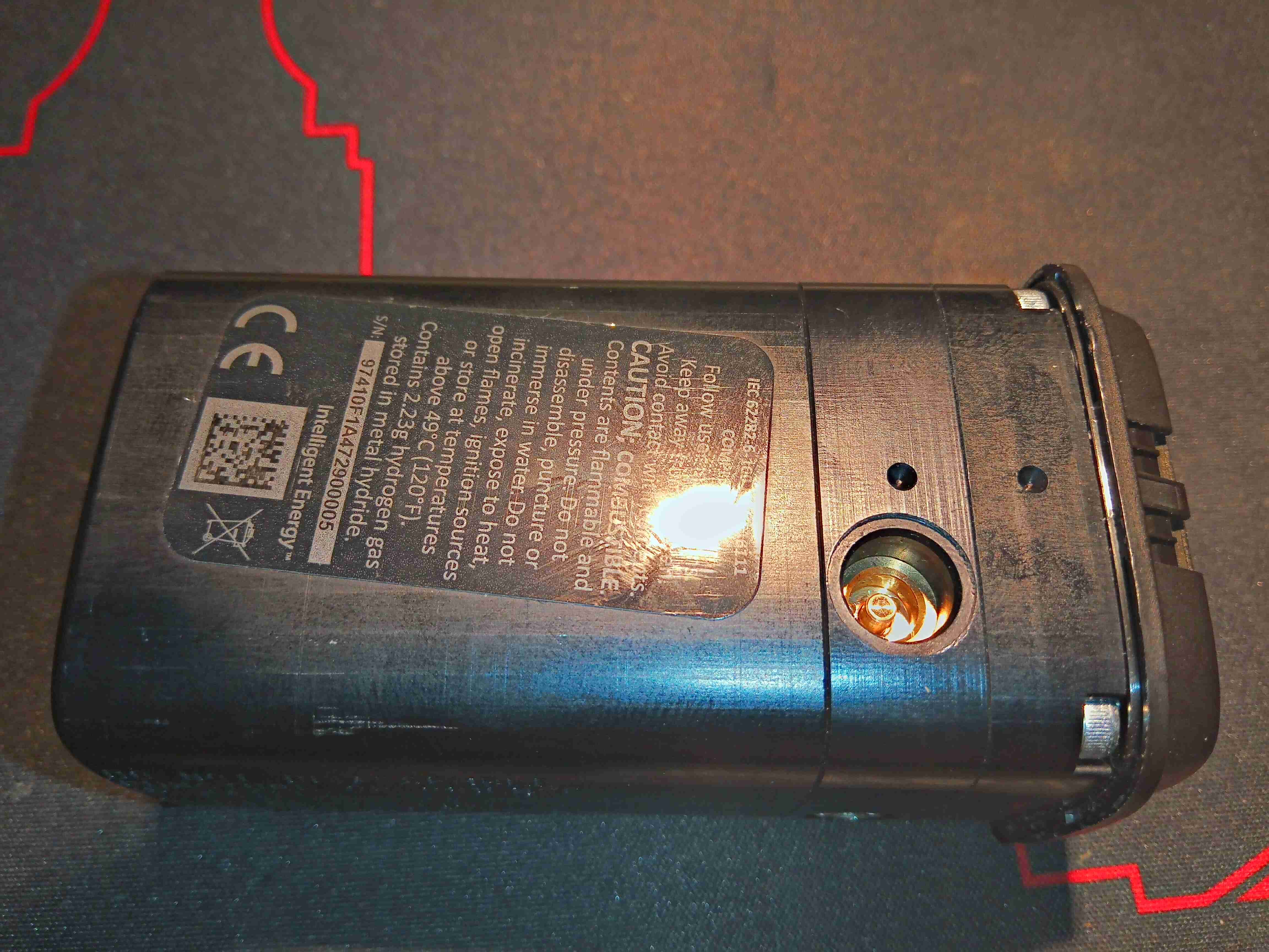
The opposite side of the unit has another label covered in warnings, and a recessed charging valve. It’s an interesting one this – there are no threads, just a brass valve with a depressable pin in the centre to allow the gas to flow. Since this needs to be charged at 20 bar, a special jig would be required, to hold any charging adaptor in place while the gas is injected. There’s no chance of getting the official part for connecting to this, so I intend to machine a brass adaptor to connect here for charging.
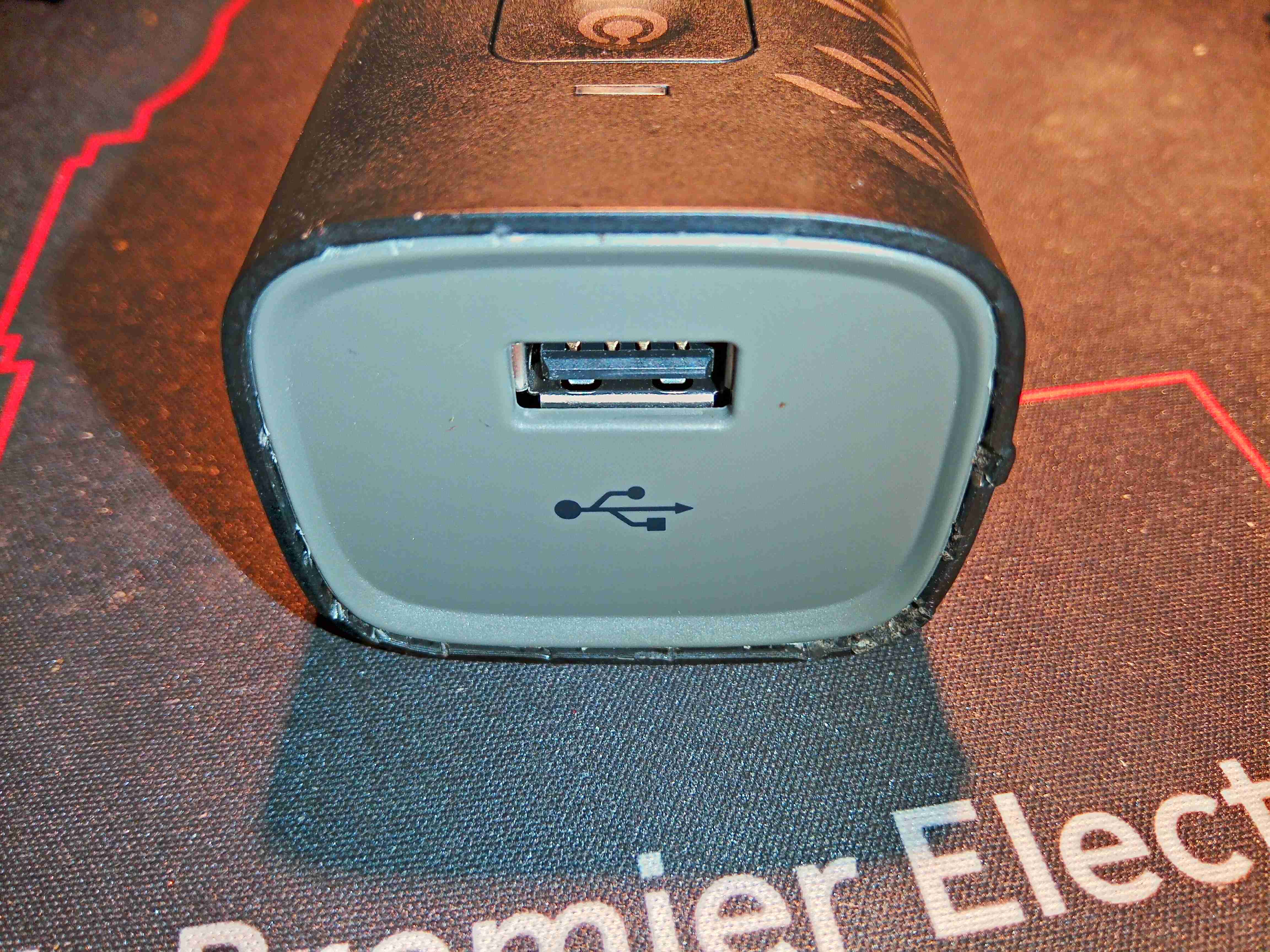
The top end of the fuel cell unit has a single USB port, rated to 1A according to the rating plate:
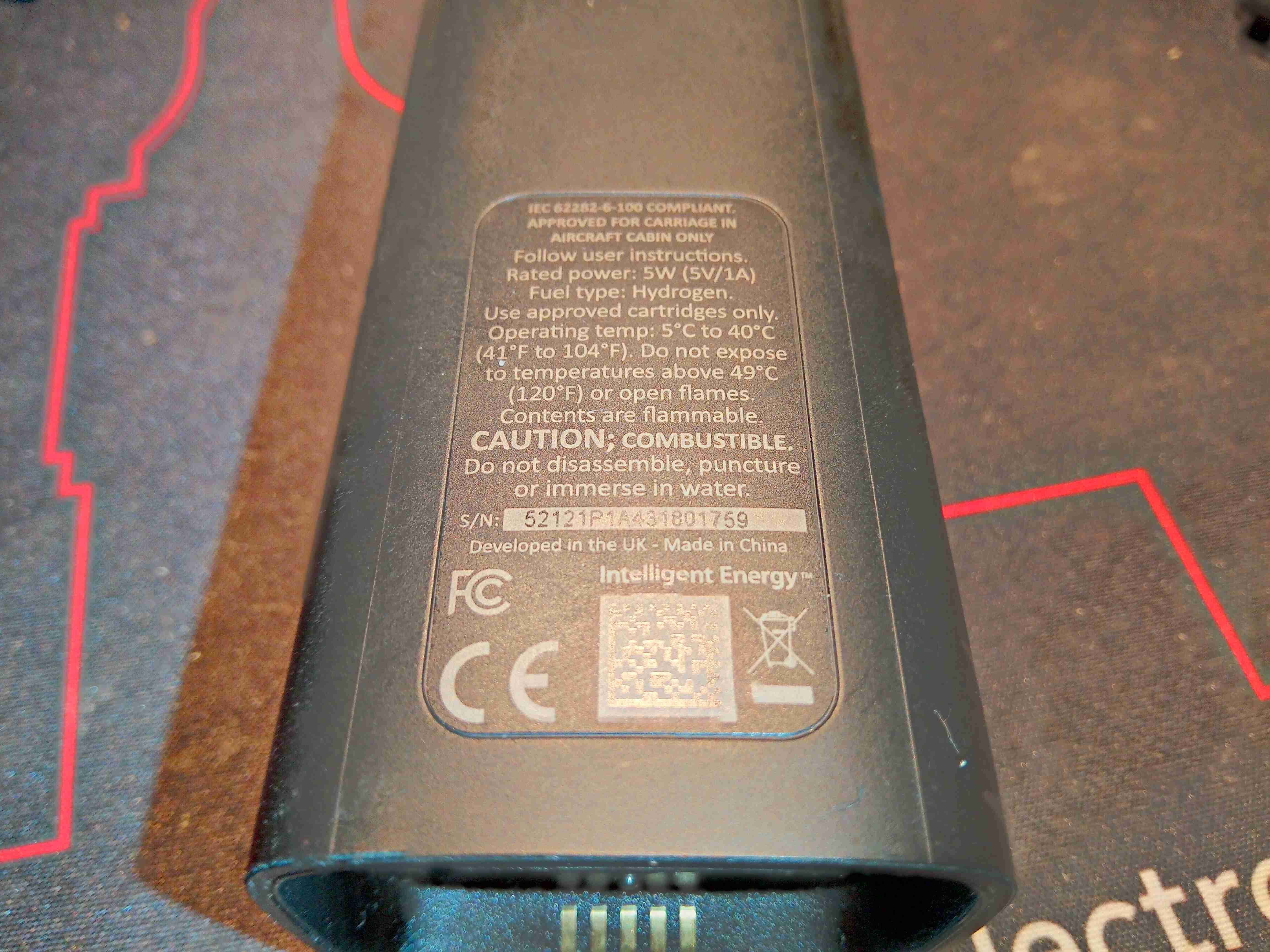
Standard rating plate with some regulatory markings, and output power.
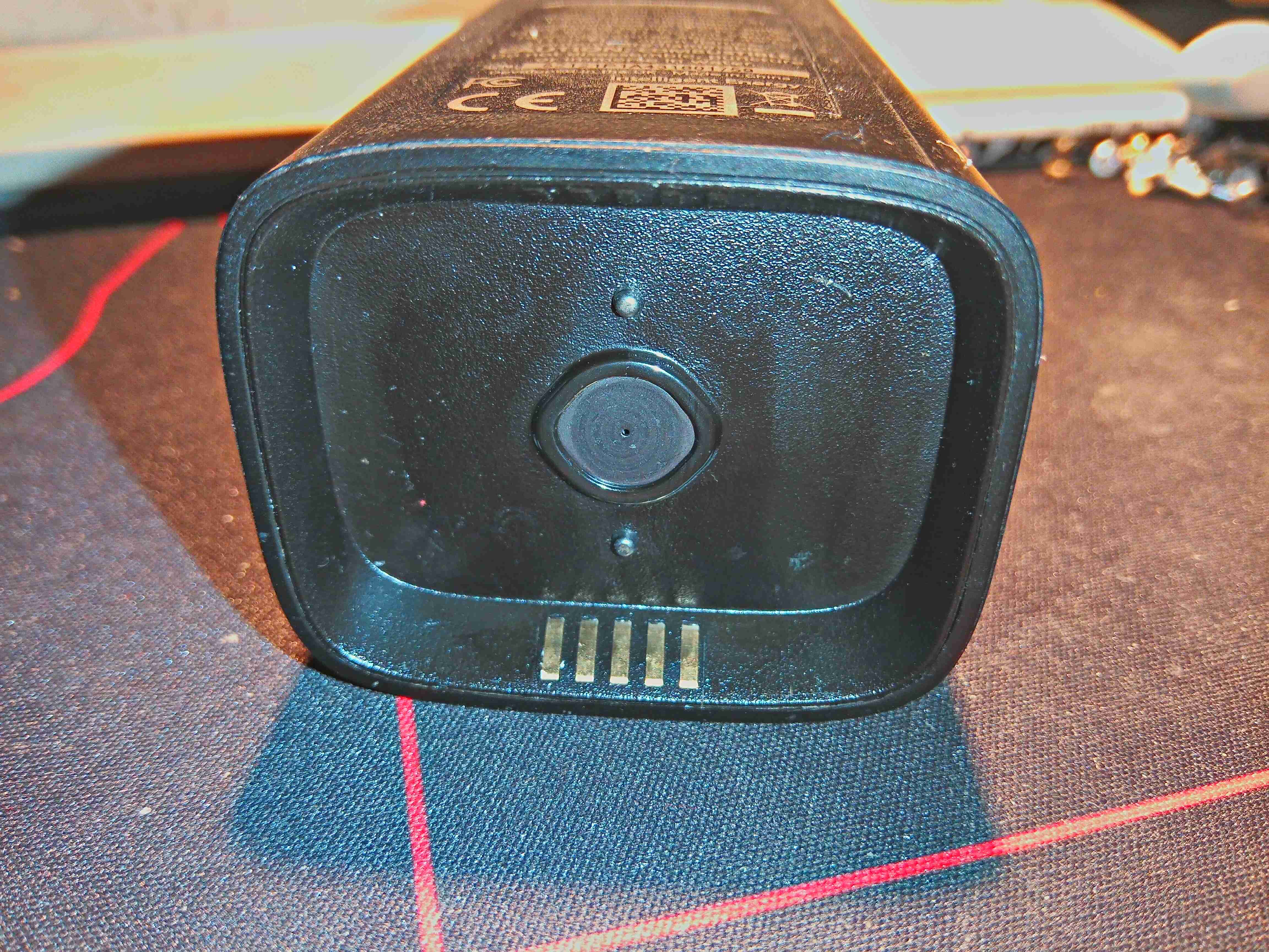
Here is the bottom of the fuel cell unit, which magnetically couples with the gas cartridge. The two pins either side of the gas port are visible, and it is these which open the valve on the cartridge. The 5 gold-plated contacts at the edge make contact with the spring terminals on the EEPROM PCB on the gas cartridge for communications. They are also used with a separate base for external charging of the LiPo cell contained inside. More on this later.
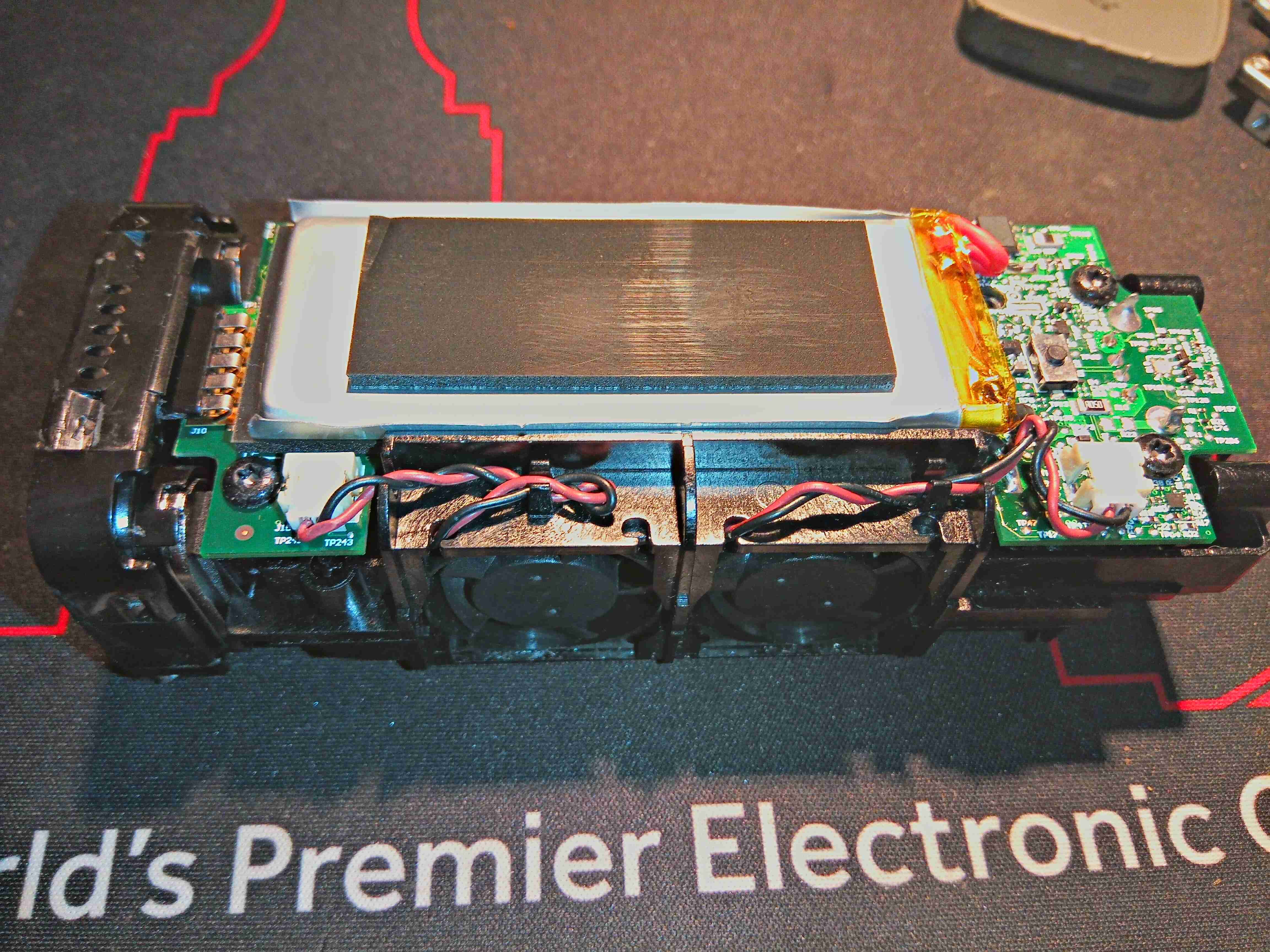
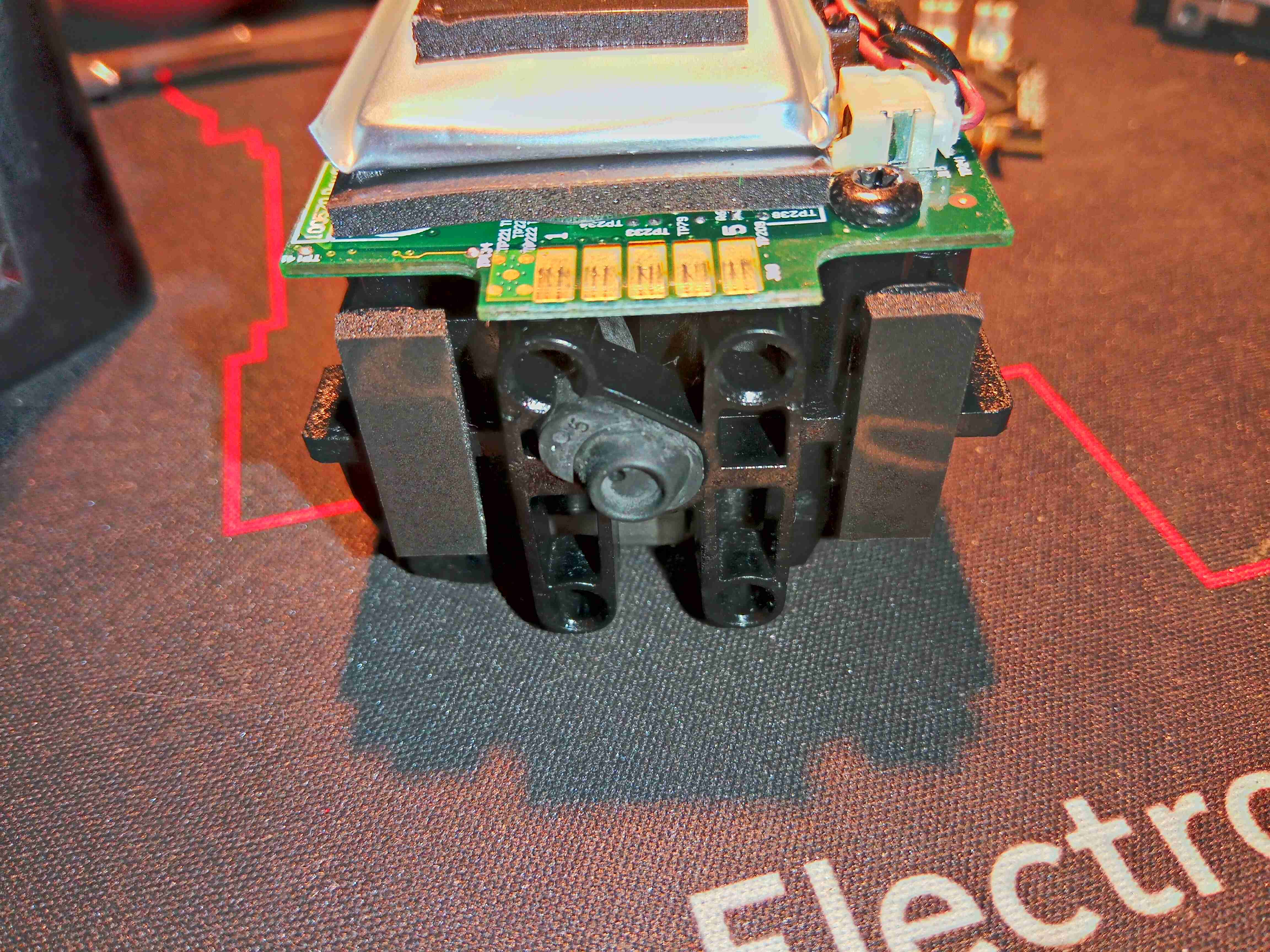
The main body of the cell is secured together with internal clips – and are not intended to ever be opened without damage, but here is the core of the unit. There’s a large Lithium Polymer cell on the top of the main board, which is required to actually get the unit going in the first place. I suspect this is also used to buffer the output from the PEM cell itself, and provide the maximum of 1A output current. (My unit would not charge a device even at 500mA when it arrived, until the internal cell was charged up – a red LED was lit just before the unit shut itself down).
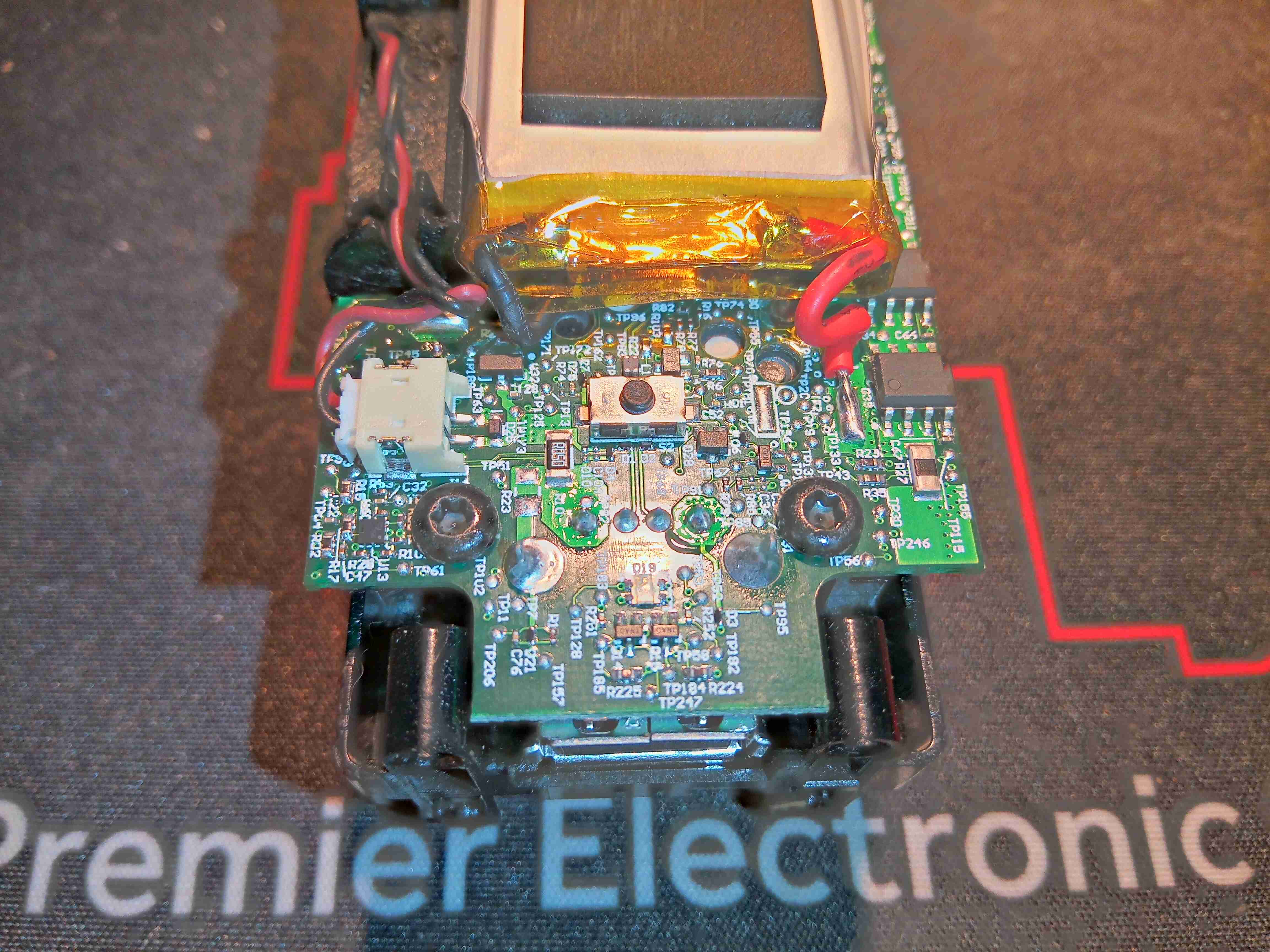
The top of the board has the single user button & the USB port. This port is enabled for communications – there used to be an app for phones that would show some statistics about the unit to the user.
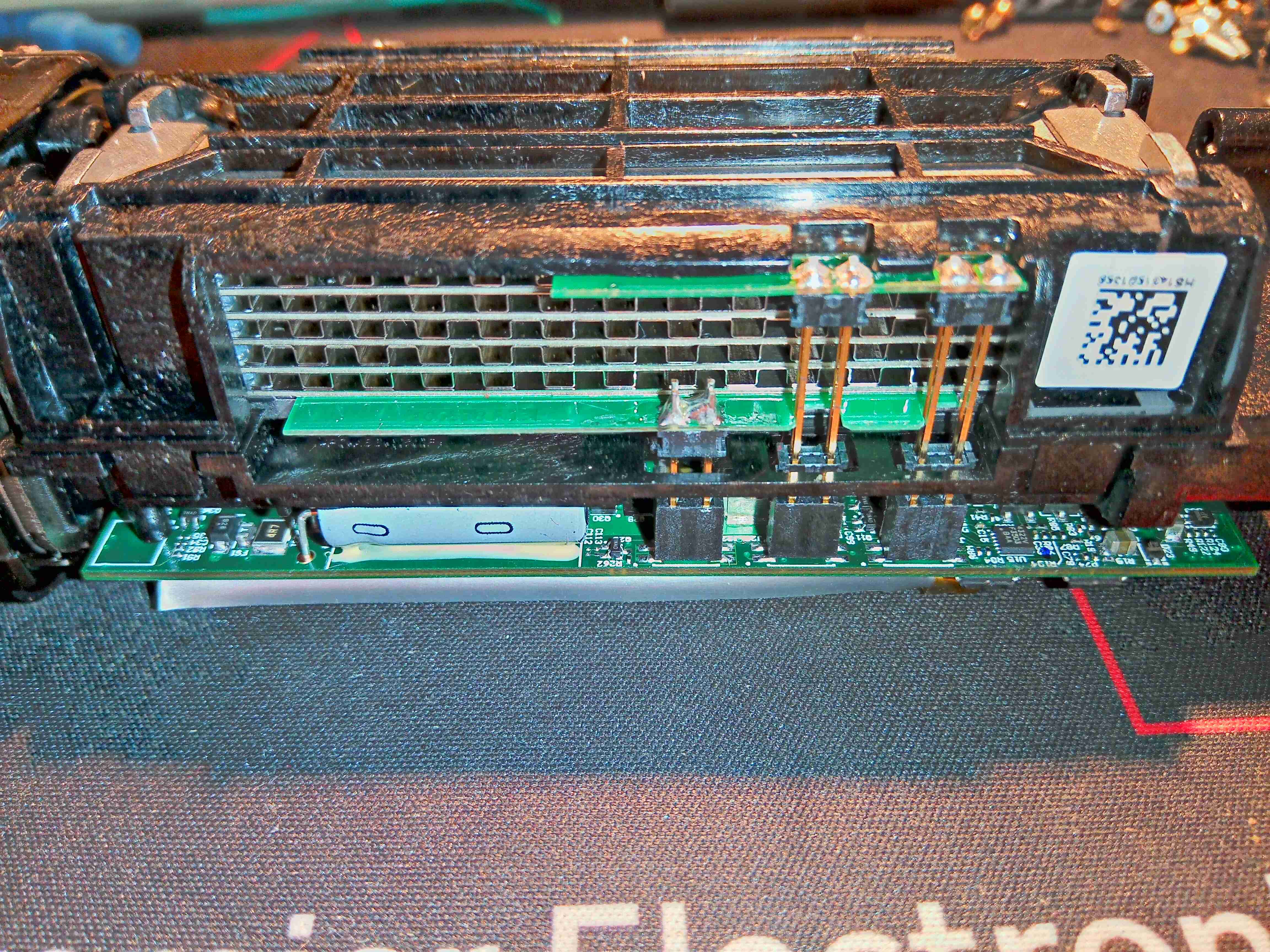
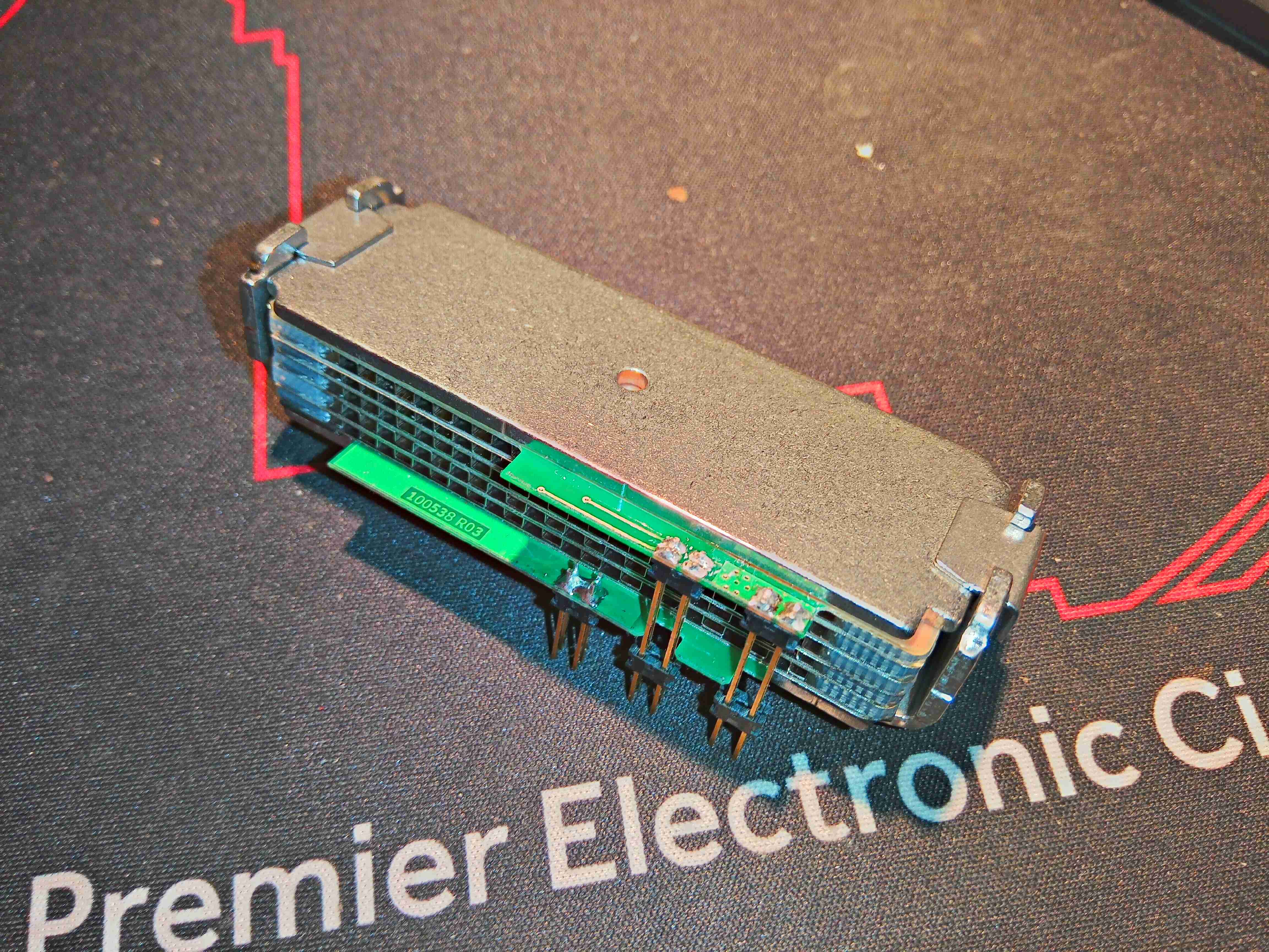
Turning the unit over shows the PEM Fuel Cell itself, a stack of 5 plates in series. There are 5 connections into the cell unit – main power output terminals, and a pair of terminals for a thermistor, which is buried right in the centre of the cell at the top, to measure operating temperature.
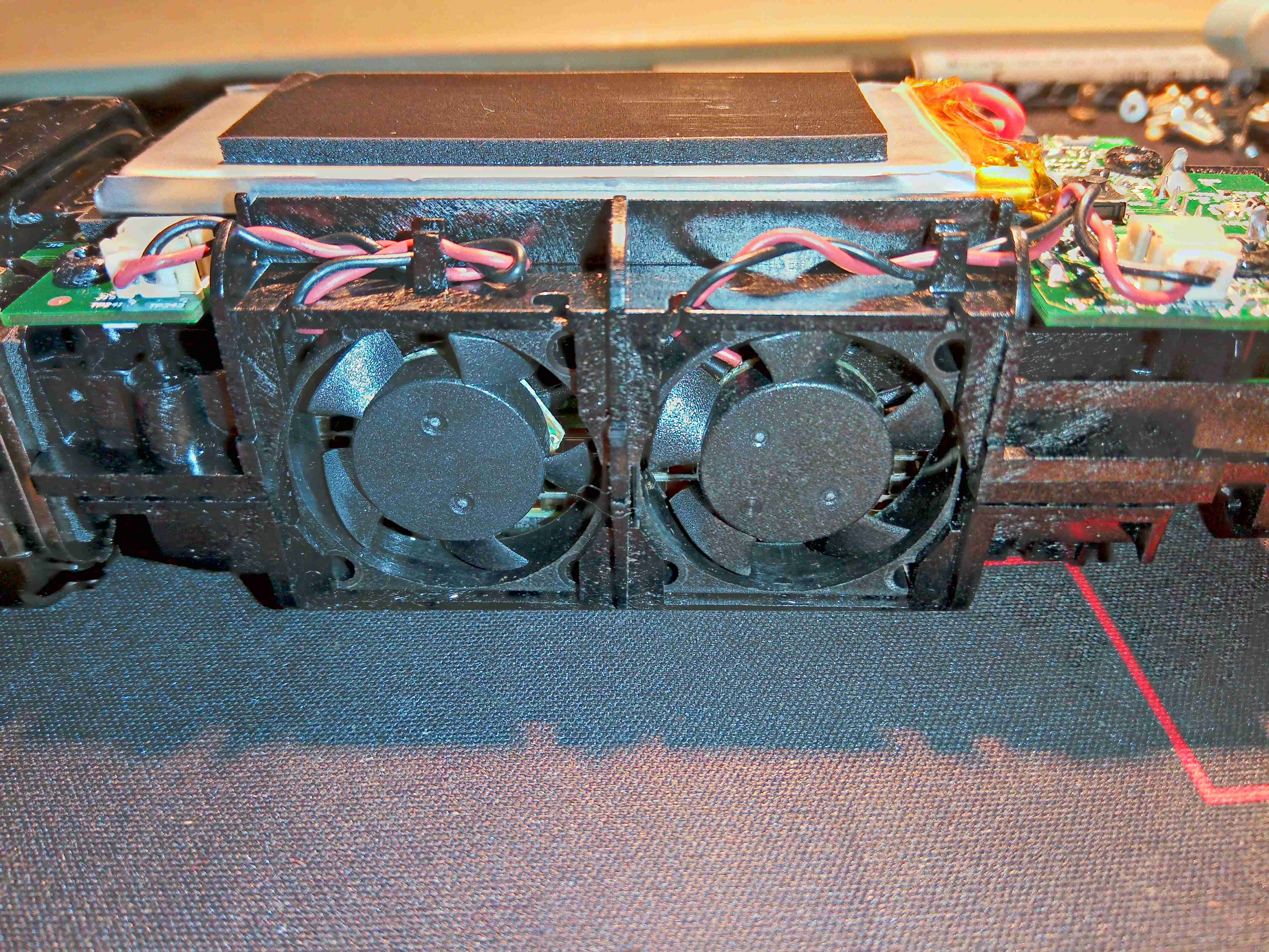
The other side of the frame holds two tiny fans, which waft some air through the channels in the fuel cell plates. This will both be for cooling, and to ensure that Oxygen can get into cell assembly to react with the incoming hydrogen.

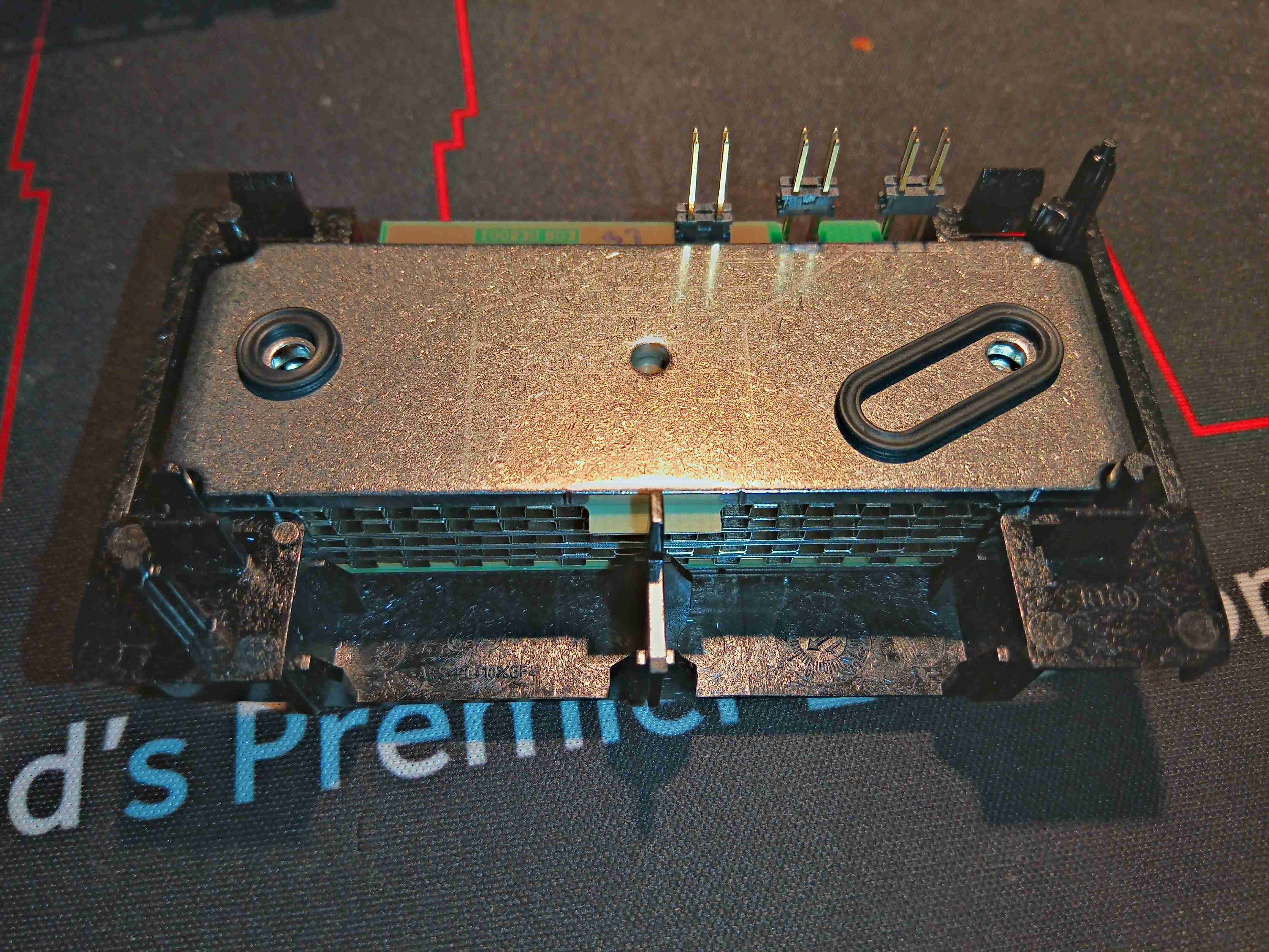
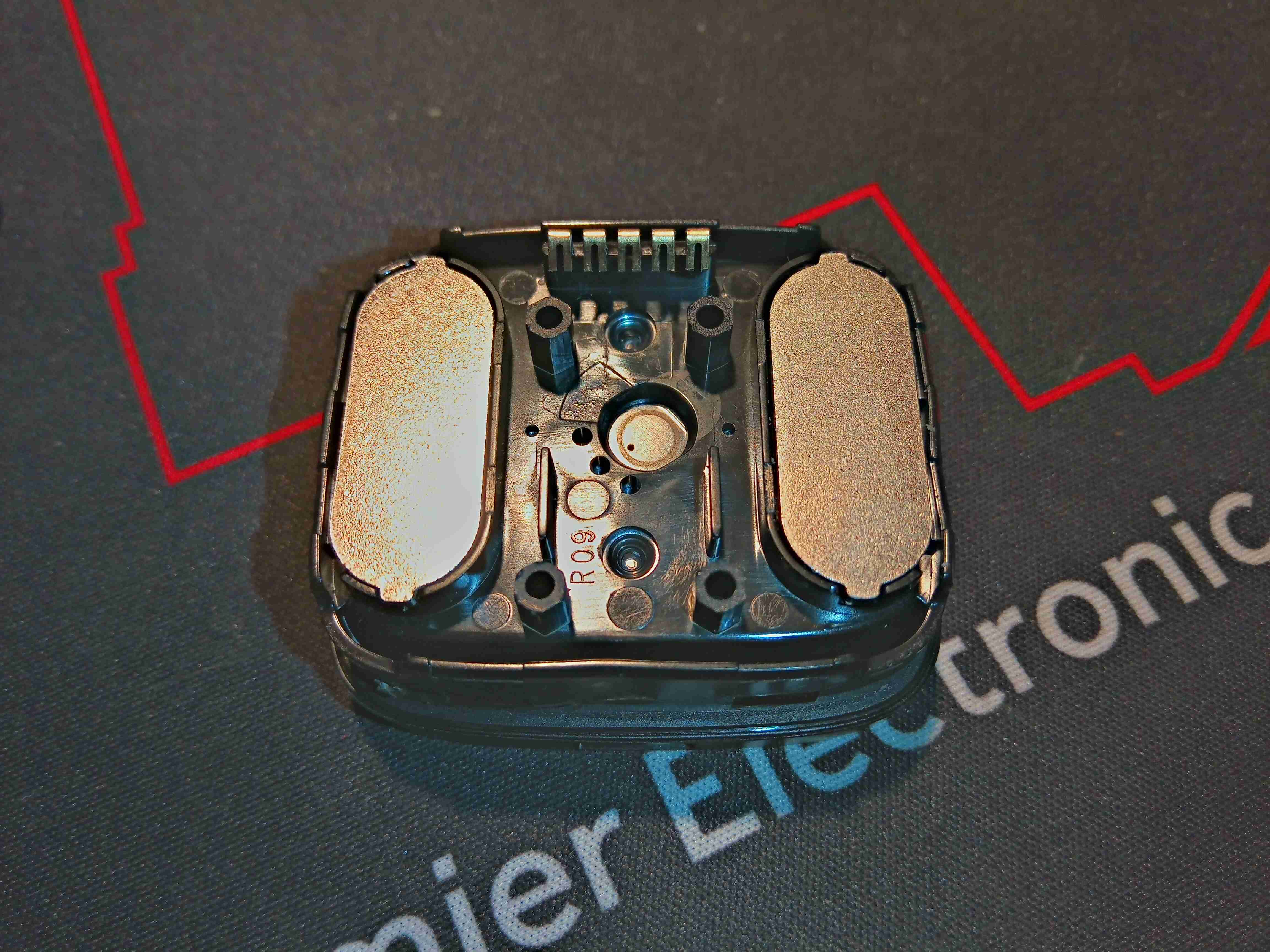
The fuel cell unit clips off the top of the main frame, exposing the two gas control valves. The one on the left regulates the gas input from the cartridge, while the one of the right is regulating the gas outlet to atmosphere. There is also the port of a pressure sensor popping up to the left of this outlet valve.
Here’s the bottom of the fuel cell module, with a pair of rubber seals on the gas ports, which interface with the faces of the valves. The H² gas inlet port is on the left.
Some more unclipping of plastic frames allows the bare module to be removed. This is a really heavy-gauge piece of steel to clamp the module together, secured by spring clips.
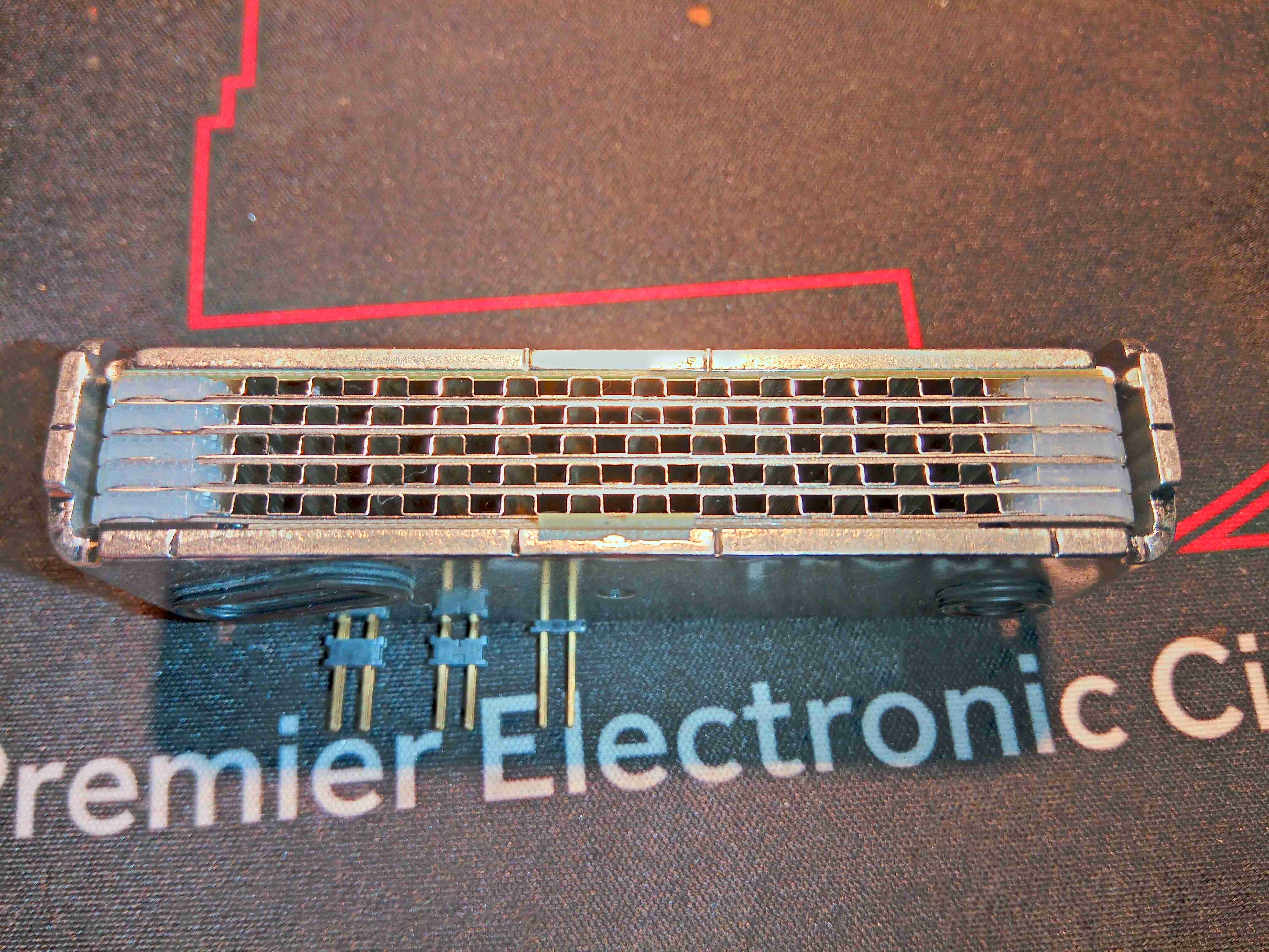
Here’s the edge of the module, showing the individual plates. There are silicone seals between them to seal the gas ports, and a thin PCB material at the top & bottom as electrical contacts. The plates being stacked together means these are all in series, providing about a 4.6v output voltage.
Here’s the back of the cartridge adaptor, with the pair of magnets to match the ones on the gas cartridge.
This rubber grommet seals onto the metal plate in the adaptor, sealing the gas inside. The 5 contacts are visible here to communicate with the cartridge EEPROM.
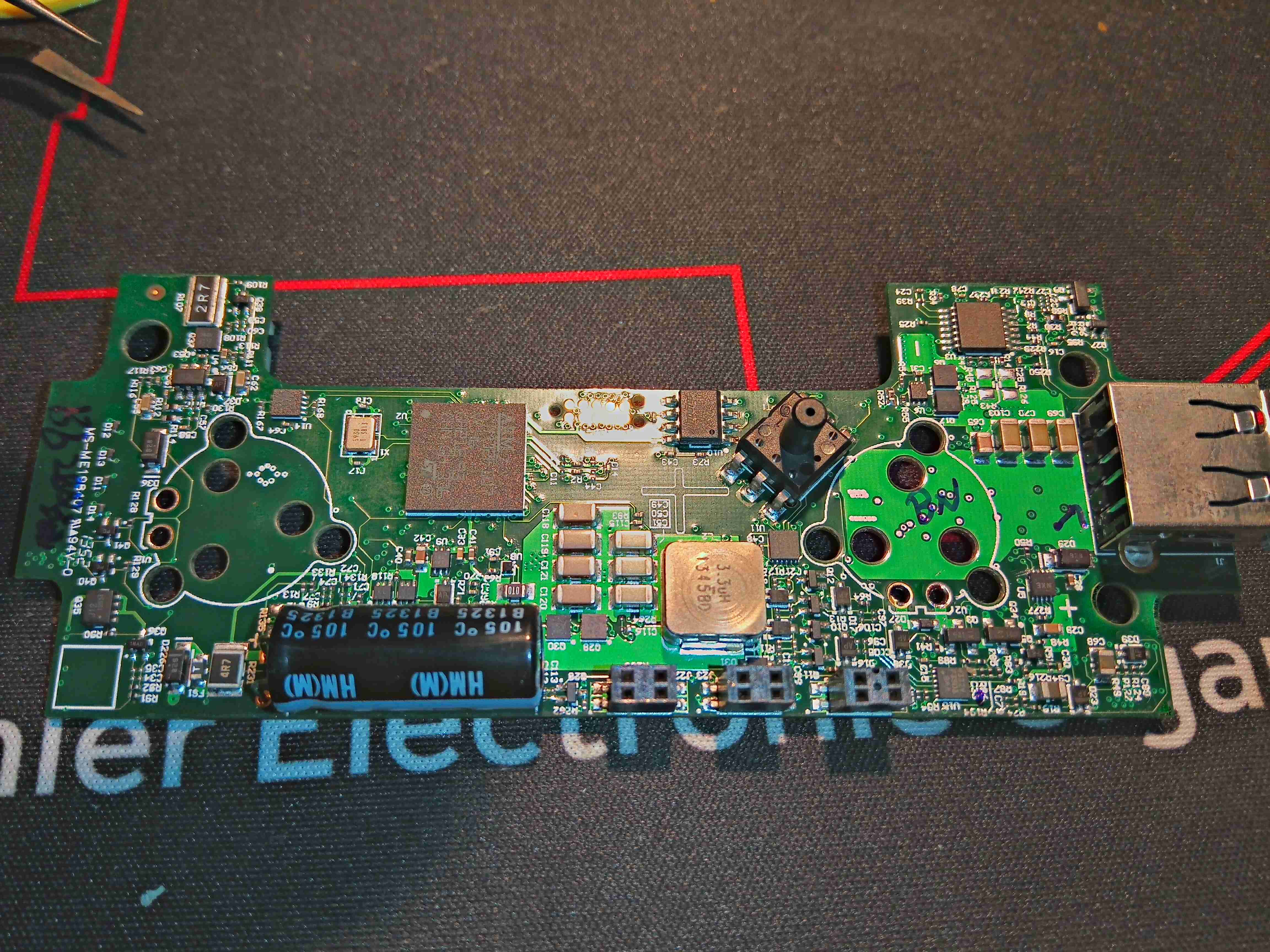
A bit of de-soldering later, and the board is free from the frame. This is very densely packed board, covered in DC-DC converters of various types. The main microcontroller is a STM32F107 from ST Micro – a 72MHz part loaded with interfaces. There’s a small WinBond EEPROM here too, which from Mike’s video, seems to be used for log data. It would be nice to get access to this board through a serial interface, to see if there’s any engineering options left in the software for some tinkering. The large inductor is part of a synchronous DC-DC converter, the controller IC for such is on the other side of the PCB.
There’s a L324A Quad Op-Amp in the top right corner of the board, next to the USB port, along with a load of discreet transistors spread throughout the board. Some of these transistors will be used for switching the solenoid coils on the gas valves. The other major part on this side of the board is the gas pressure sensor, just to the right of the EEPROM.
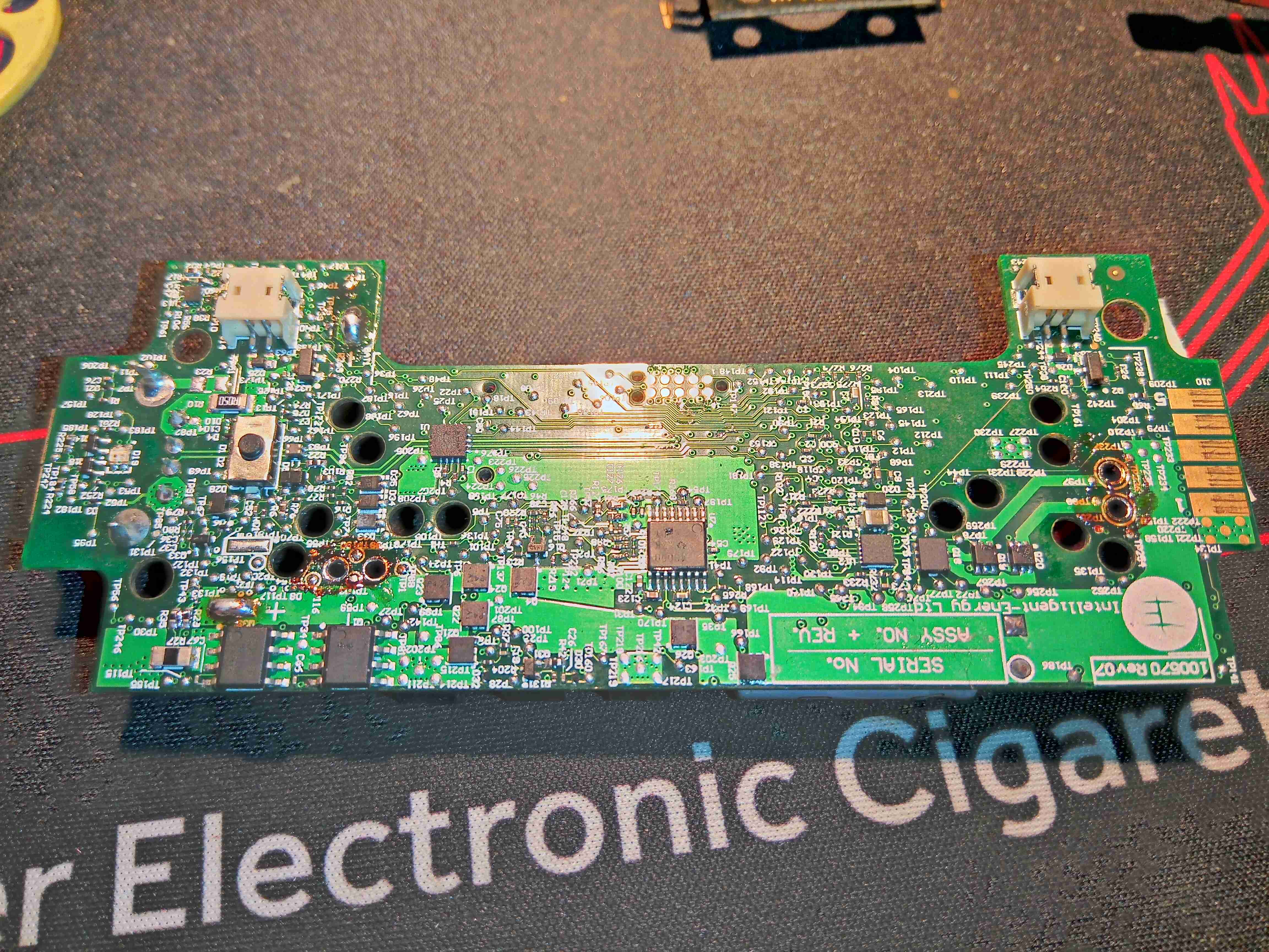
The other side of the board has even more components, the Lithium cell protection MOSFETs are at bottom left, the Synchronous DC-DC converter controller, a TPD43000 from Texas Instruments is in the centre. There are more discreet transistors on this side, for driving the solenoids & fan power control.
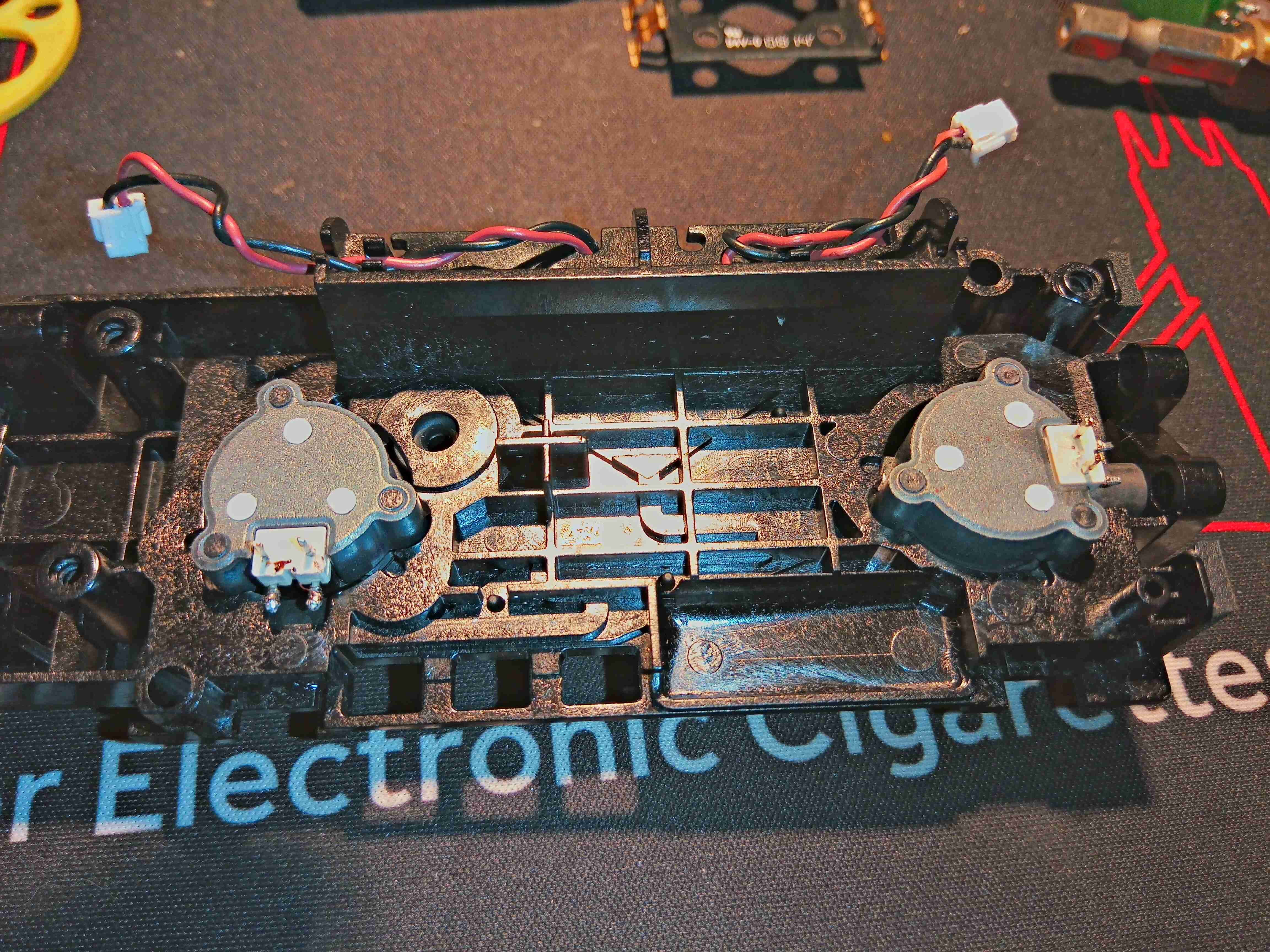
Not much remains in the frame, other than the gas valves themselves.
This is an interesting piece of tech, but it’s definitely useless – especially in the era of high capacity power banks of up to roughly 40Ah. The gas cartridges that this unit eats through hold approx. 7Ah of capacity, and at £6 a pop, it is an expensive way to charge a mobile device. I will be coming up with a way of recharging the gas cartridge though, which will involve some sideways thinking & machining of brass. More to come on that!
