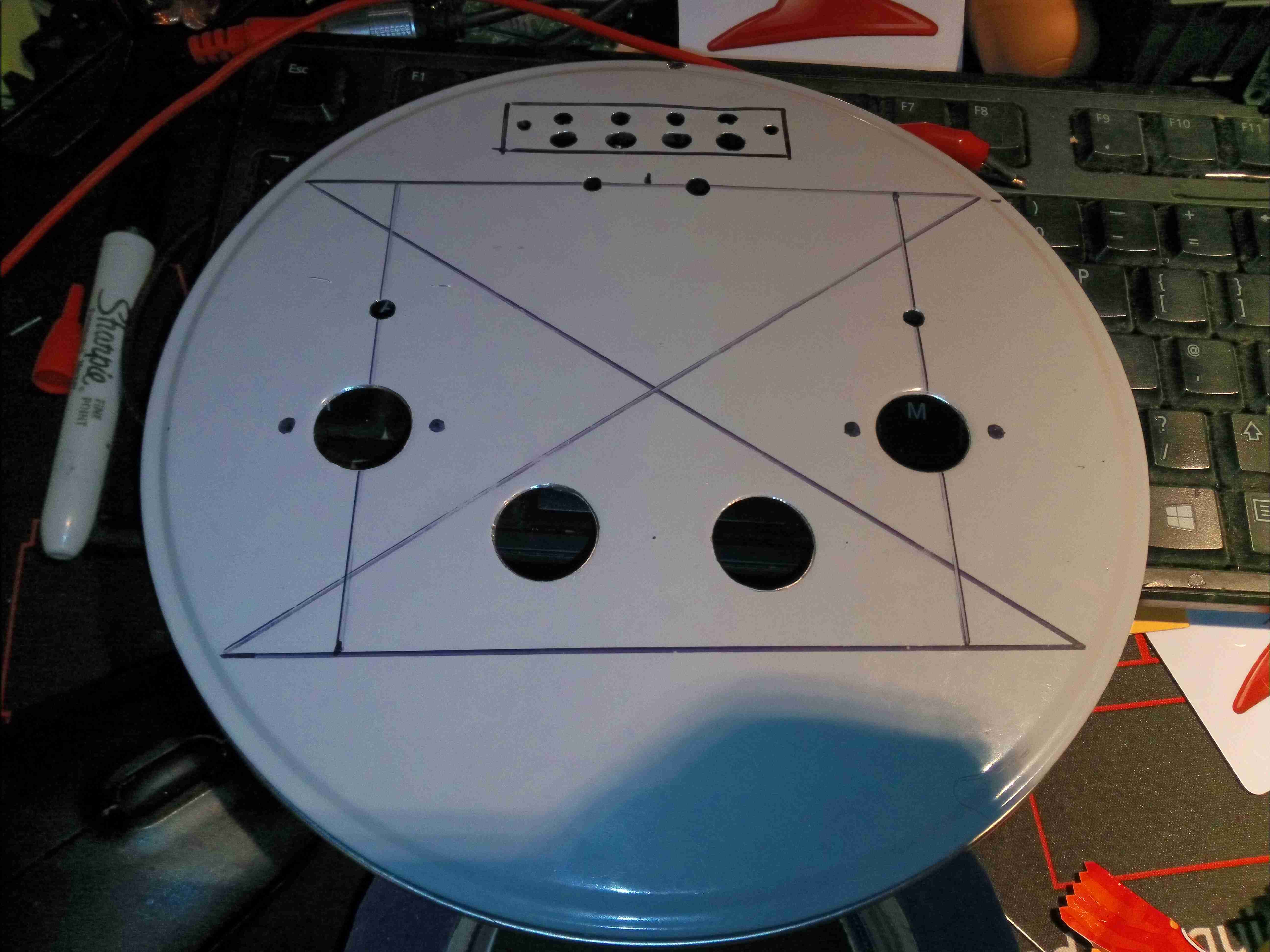
I figured it was about time I built another valve amplifier, and since I already had most of the required parts in stock, here it is! Above is the lid of a cake tin sourced from a local shop as a case, marked out & drilled for the valve sockets, output transformers & speaker terminals.
The ECL82 valve is a Triode & Audio Output Pentode in a single envelope, requiring only a single valve per audio channel. There are a pair of extra holes drilled here for a couple of EM80 magic-eye valves wired as VU meters to give a bit of a lightshow.
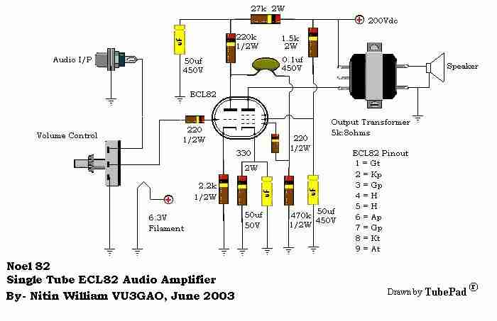
Here’s the base schematic for the Class-A ECL82 amplifier sections, obtained from the interweb. It’s pretty basic, and doesn’t mention a value for the volume potentiometer, so I used a 100K audio taper for that. Power will be supplied from low-voltage DC, running through a high voltage DC-DC converter for the anode supply of 200v, and a 5A buck converter for the 6.3v filament supply.
The EM80 side is as the schematic above, the signal input being taken directly from the Pentode anode of the ECL82. I have removed the second 1N4148 diode down to ground, leaving only a single diode.
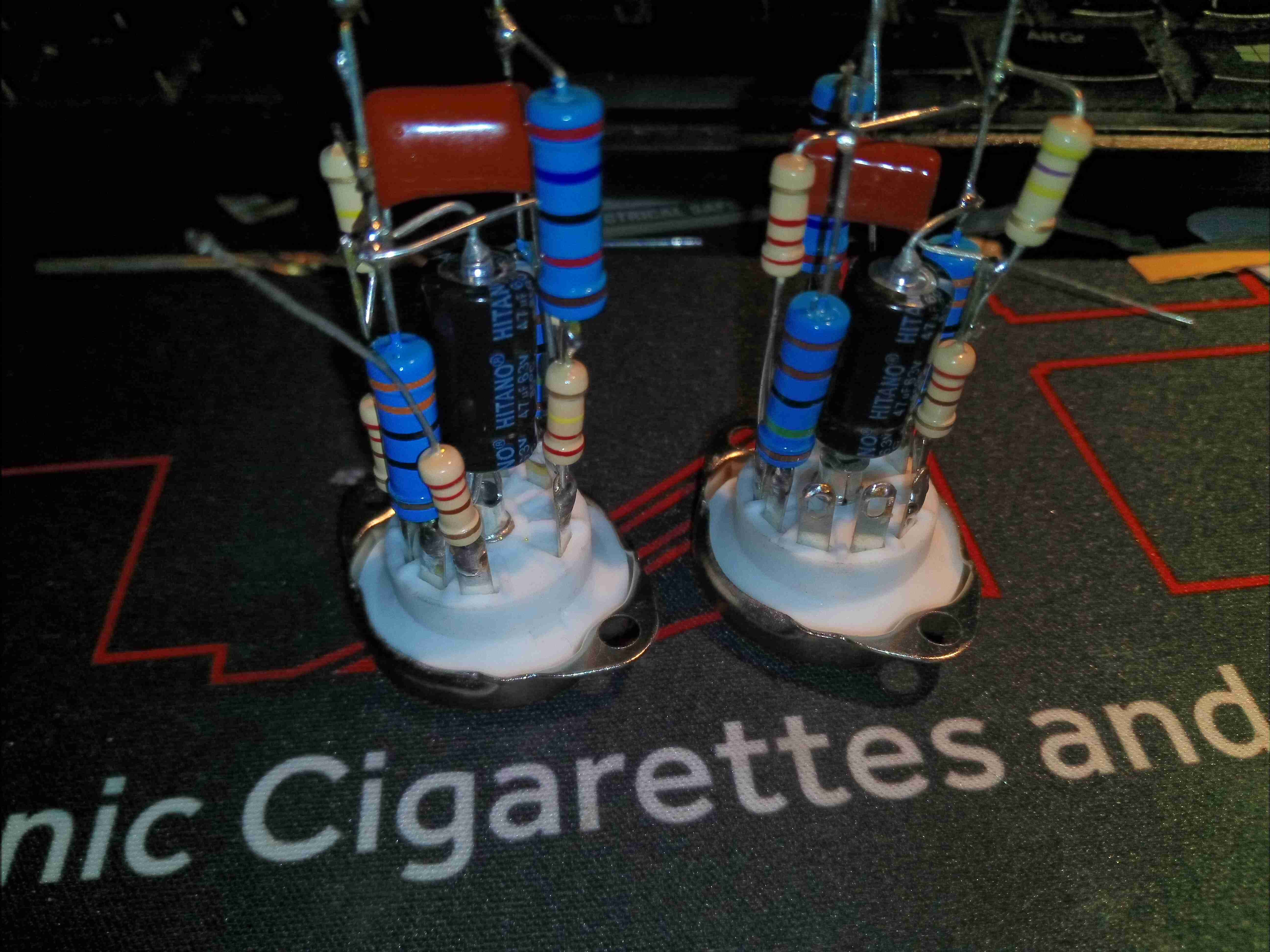
Most of the parts comprising the ECL82 amplifier stages are mounted directly on the back of the valve sockets, requiring only a 6.3v filament supply, 200v anode supply & audio I/O connections. Axial electrolytics have been used for ease of assembly, even though they’re getting a little expensive nowadays!
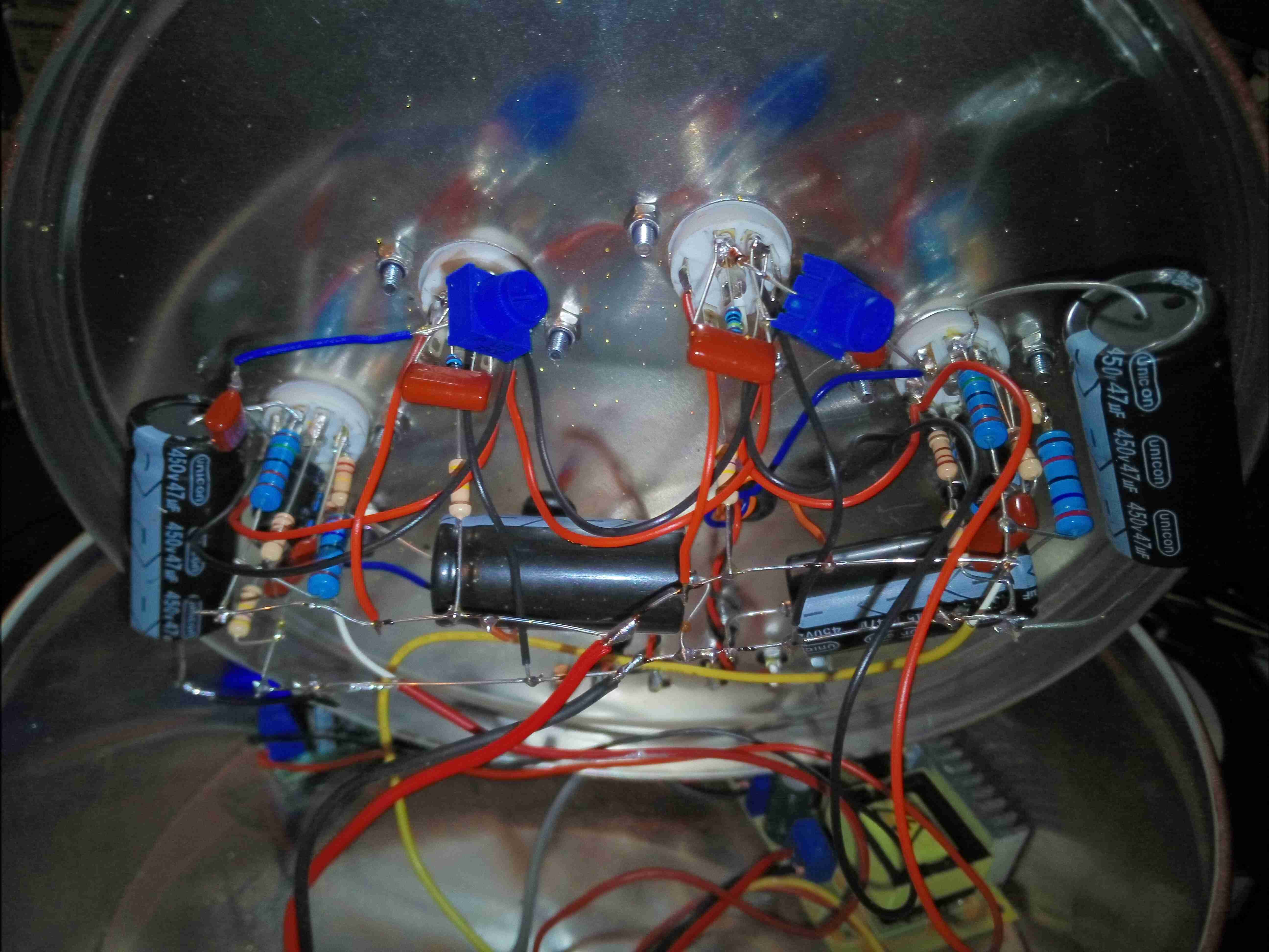
After fitting the components to the top lid, point-to-point wiring is used to connect up the valve socket assemblies. Some large electrolytics provide B+ smoothing, and all the filaments are daisy-chained in parallel. Audio is brought in on micro-coax from the I/O, and straight out to the output transformers on twisted pairs, keeping the audio wiring away from the B+ voltage.
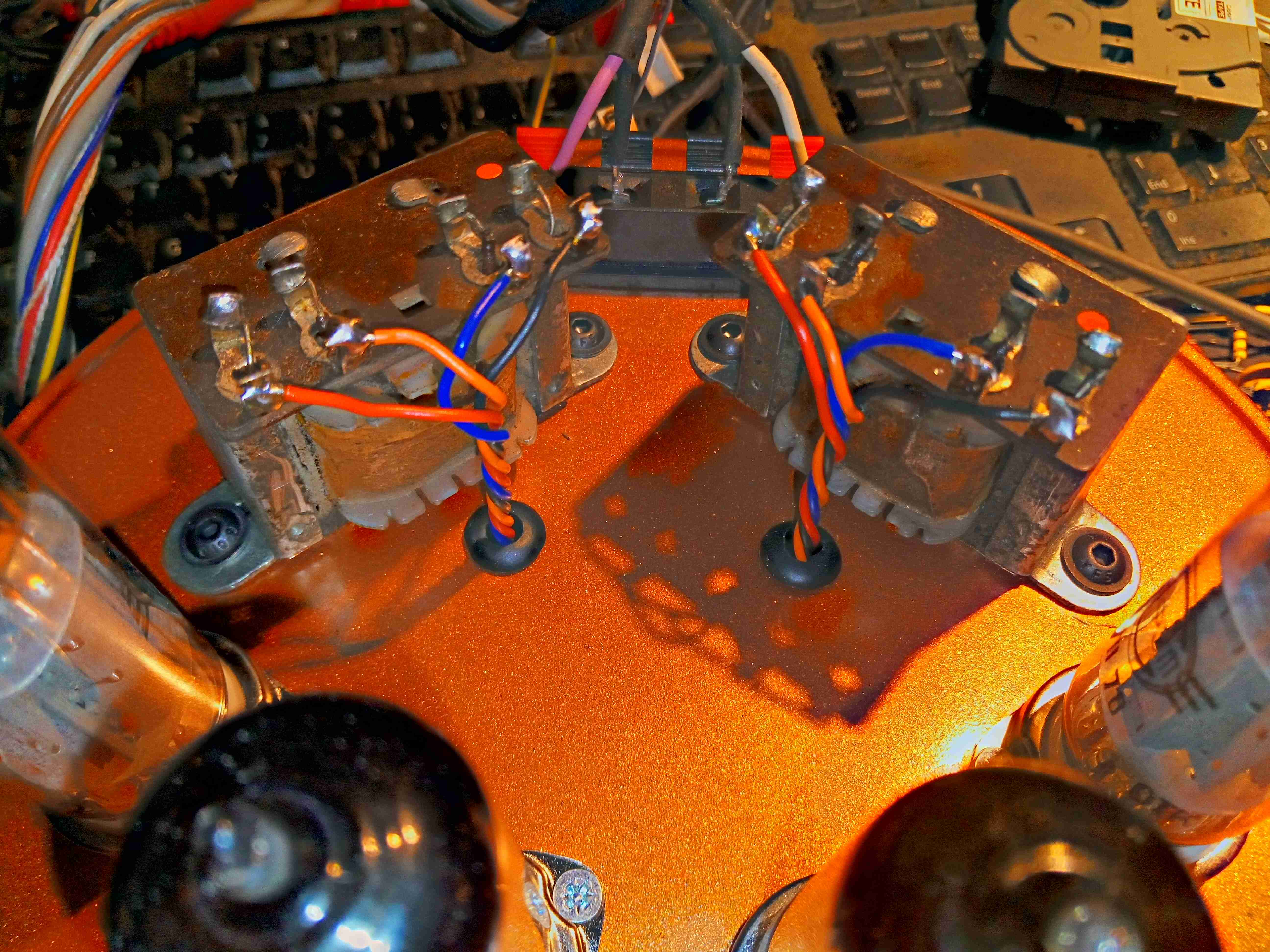
The audio transformers, from a 1960’s Philips Radiogram, are mounted behind the valves, with the wiring emerging through holes in the case. I’ve already done the paint job here, in metallic copper.
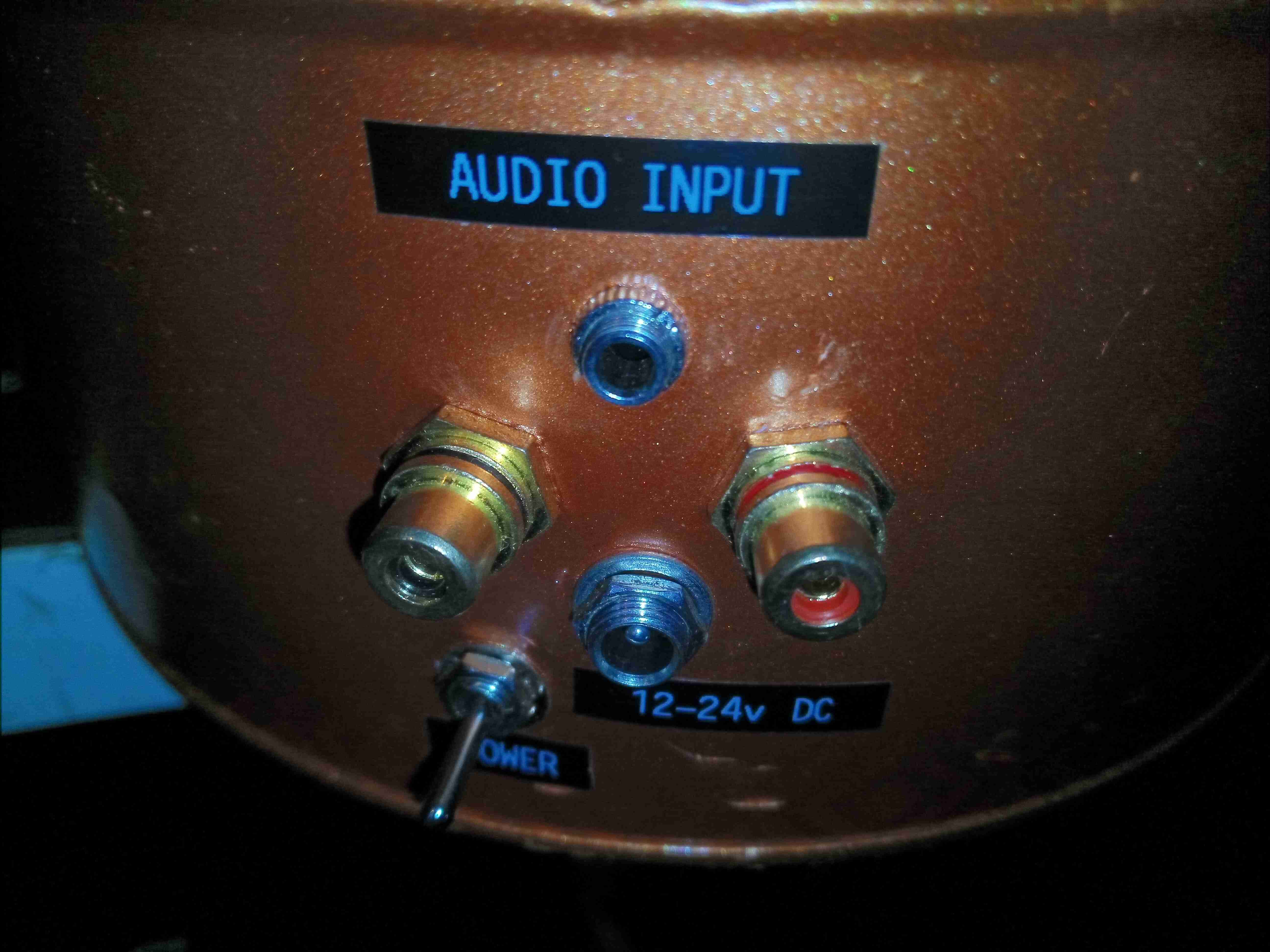
Audio & power sockets are on the back of the tin, with both 3.5mm Stereo inputs & phono inputs. A DC barrel jack takes care of the power, accepting 12-24v.
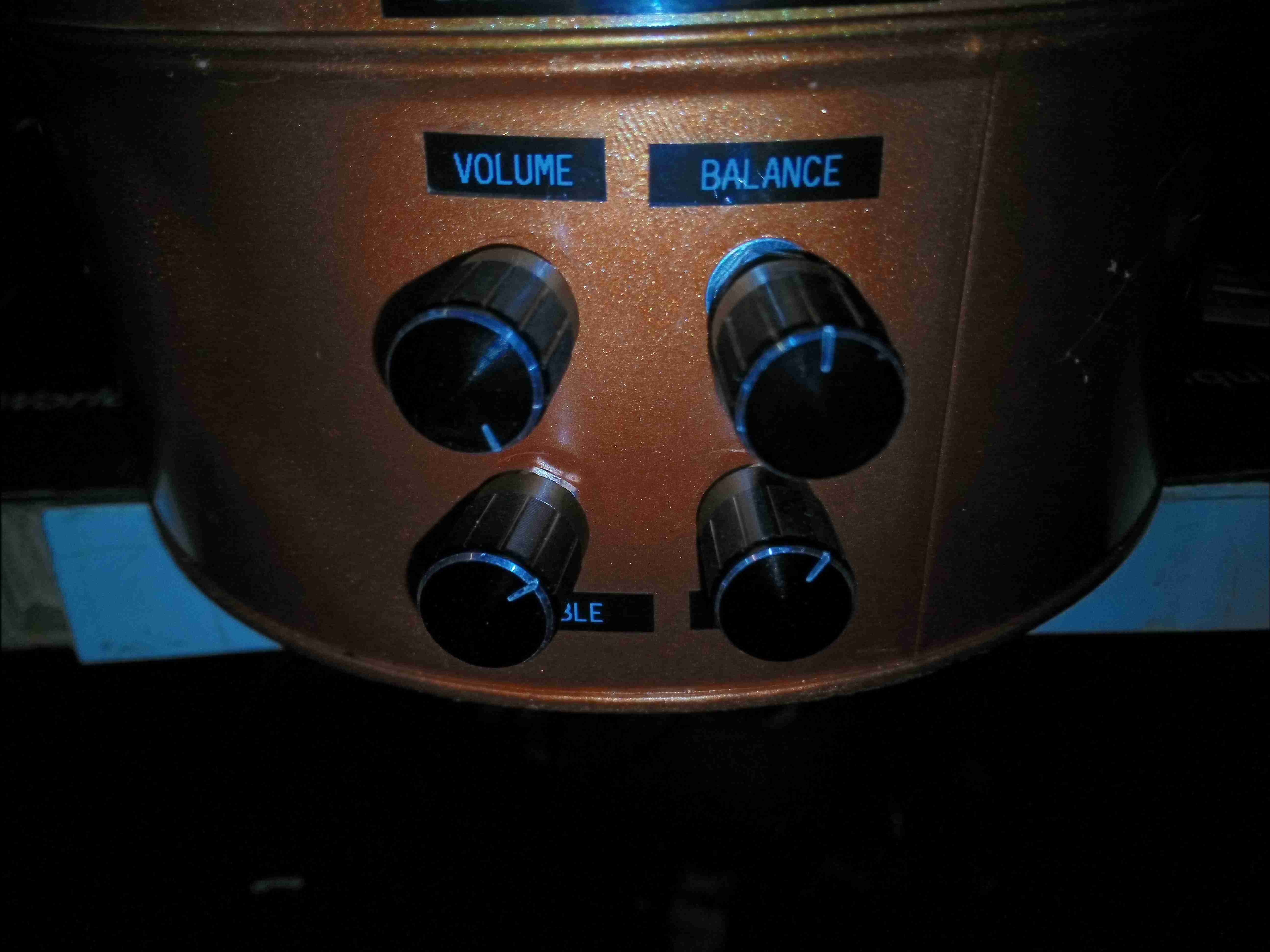
Controls on the front provide volume, balance, bass & treble adjustments.
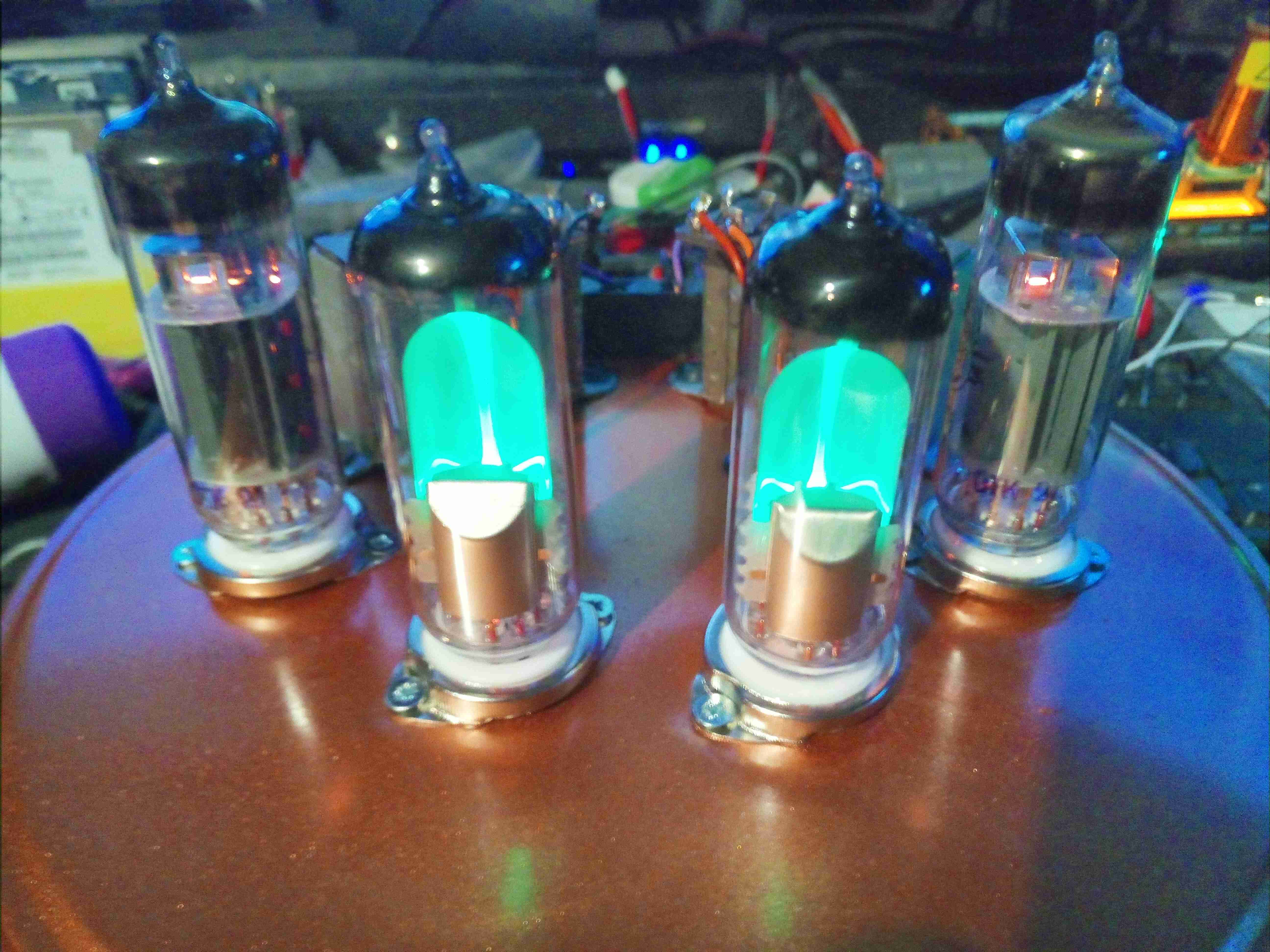
Here’s the amplifier with it’s valves glowing nicely. Total power consumption is roughly 30W, using NOS Svetlana ECL82s & EM80s. In operation there is no hum or noise in the background, with no audio input the connected speakers are entirely silent.

What a cracking design, with respect I would love to use your design to build one of my own. I’m experienced in modern semiconductor electronics but I have yet to try anything with valves. The voltages make me very wary!
Thanks for showing us this amp. How does it sound?
Hi Jon,
I’d love to take credit, but the circuit design isn’t my own! I borrowed it from elsewhere on the intertubes 😉 The hardware implementation of it though definitely did come from my head. 😉
As Dave Jones would say over on the EEVBlog, valves are just J-FETs with pilot lights! The anode voltages in this (+200v) will certainly give a nasty nip, especially with the bus bulk capacitance, so I’d definitely be careful there. It’s a simple enough starter project though for your first foray into valve tech. The one component you may struggle to get hold of is the output transformers, at least for sensible money. I am currently doing some experiments with PA 100v line transformers as replacements for expensive valve output transformers, as they’re much cheaper, but I’ve not managed to get the time of late to dig into it.
As for how it sounds, I certainly have no problem with the audio quality, even with the hearing damage caused by many years of Music Festivals & datacentre work!
Cheers
On the O/P transformer: I rebuilt my old 8W ELL80 based stereo with whatever I could find. It was just a fun project so didn’t want to spend 2x £80 on o/p transformers. The right ratio, 10K to 8ohm would be given by a 15W mains torrroid 115-0-115V / 6.3V (works out just OK with 10% regulation transformer gives 7V no load). So, no HiFi, but using negative feedback with 1K8 to 82ohm in cathode of first triode overcame the serious gain loss above 10KHz and no measurable roll-off until >15kHz..