These projectors were very popular when they first appeared on the market with the laser hobbyist community, and for very good reason – they contain a massive array of 445nm Royal Blue laser diodes in their optics engine. Originally very expensive, these units can now be had for under £50 on eBay, usually with damaged DLP chips.
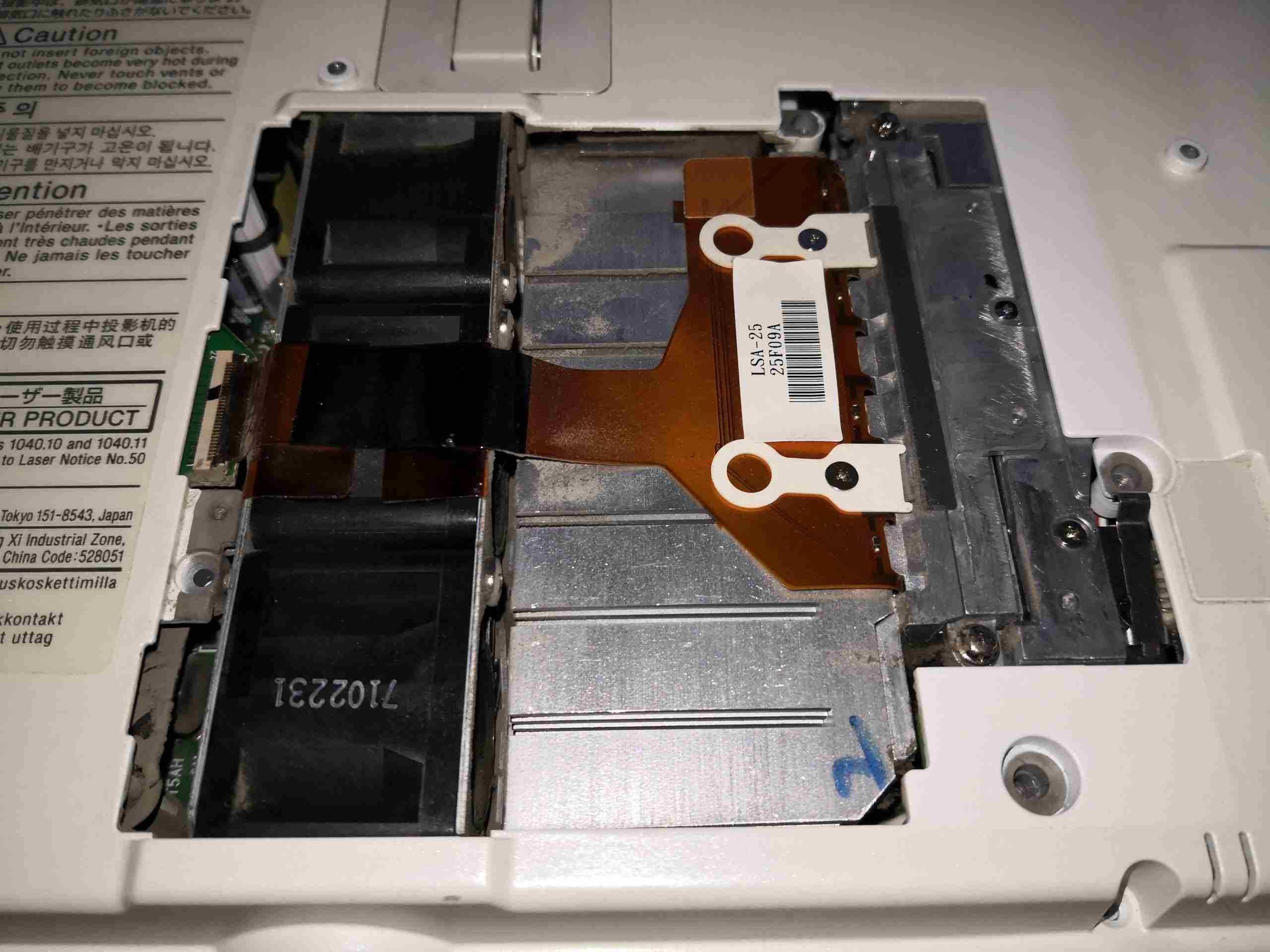
Under the door on the bottom of the projector is the 445nm Laser diode array module, itself secured in place with security screws to the beam combiner. The rack of 3 high speed fans to the left draws air over the substantial heatsink.
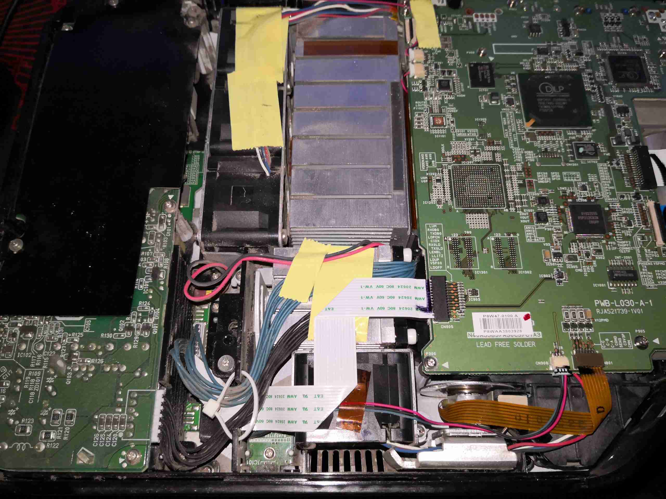
After removing the shell securing screws, the top cover comes off with the button panel. This gives a view of the internals, mostly PCBs at this stage.
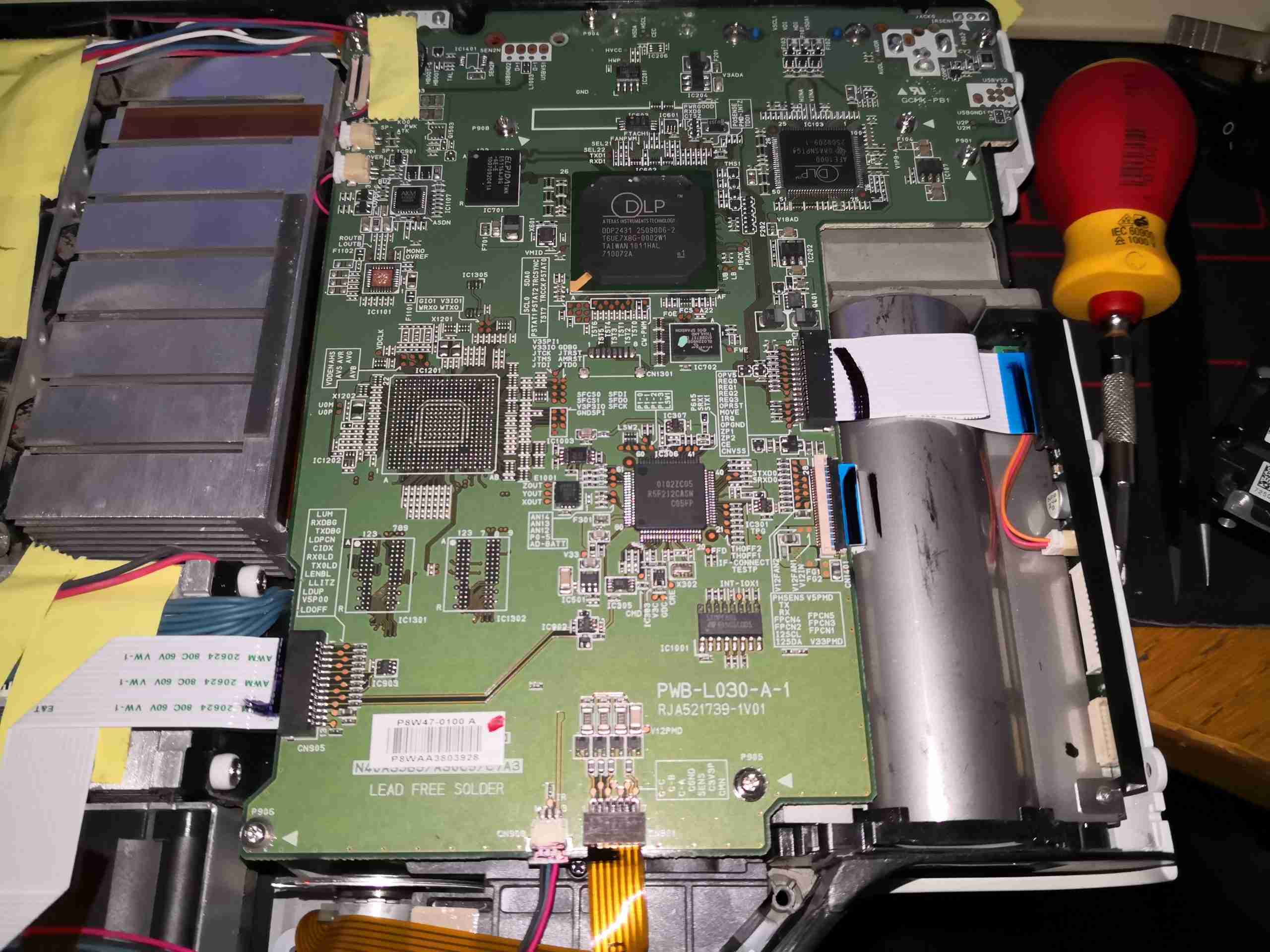
On the left side of the projector is the main control PCB, with the video handling circuitry.
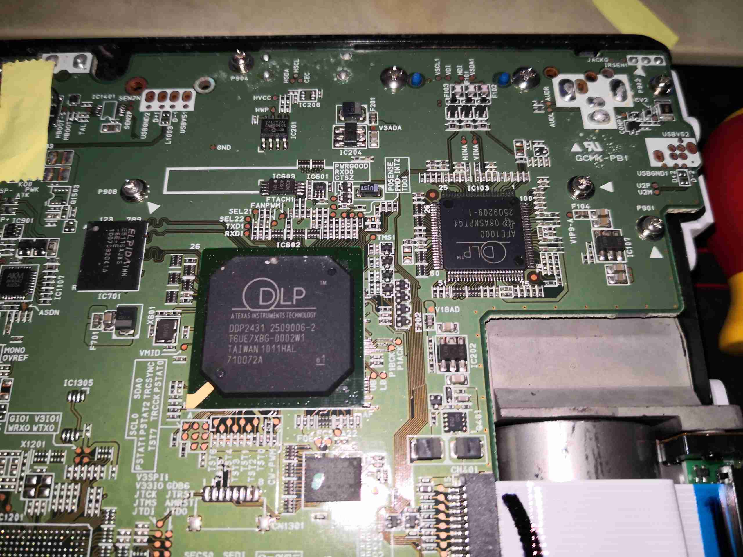
At the top of the board is the main DLP image processing chipset, these two components are actually custom parts, so no datasheets are available. The main DLP IC has some DRAM & a Spansion serial flash for firmware storage. There’s also a small audio amplifier on the left to drive the onboard 2W speaker.
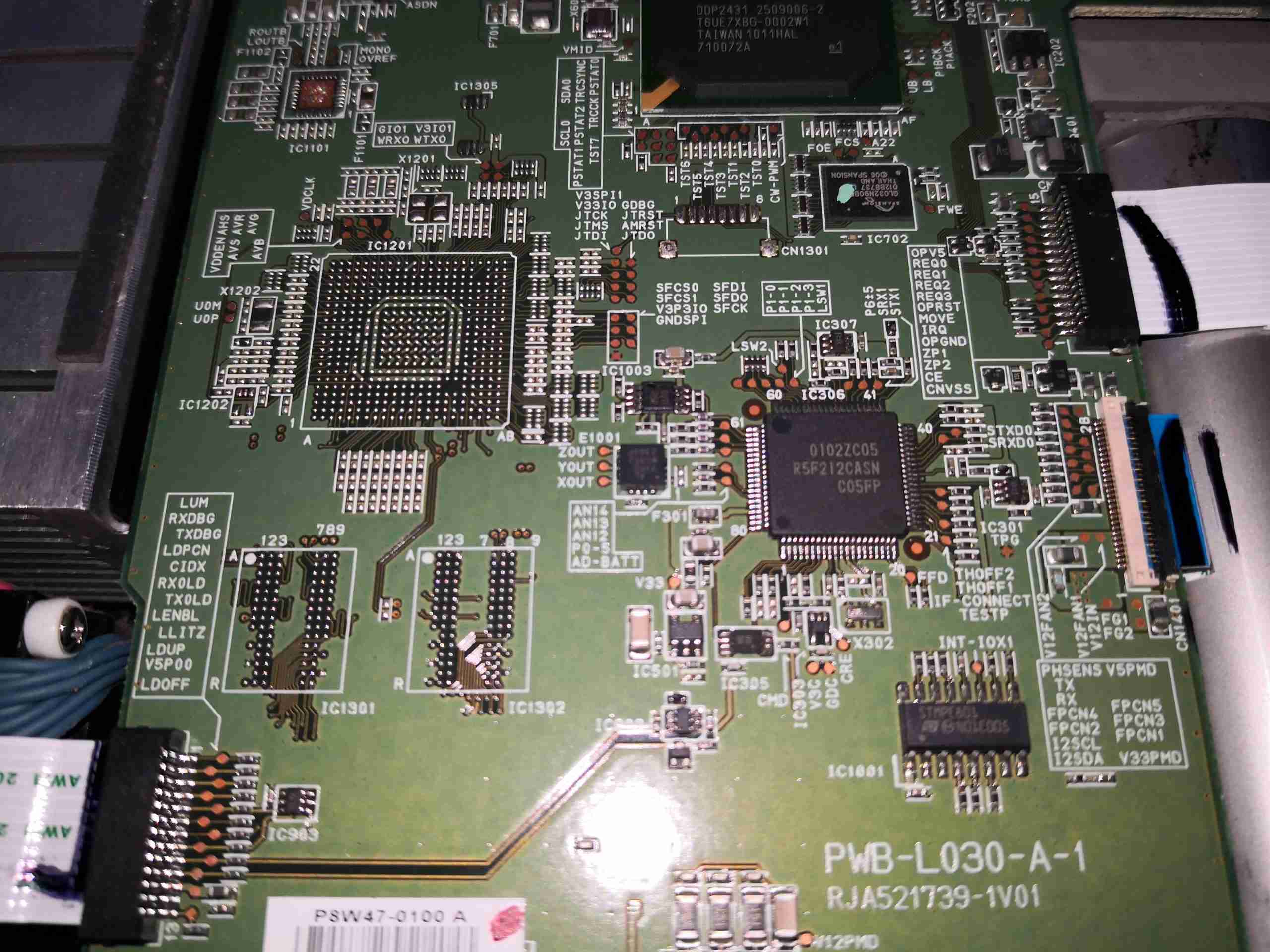
Further down the board sees an unpopulated BGA footprint, with more space for DRAM. The main system microcontroller is on the right, a Renesas part.
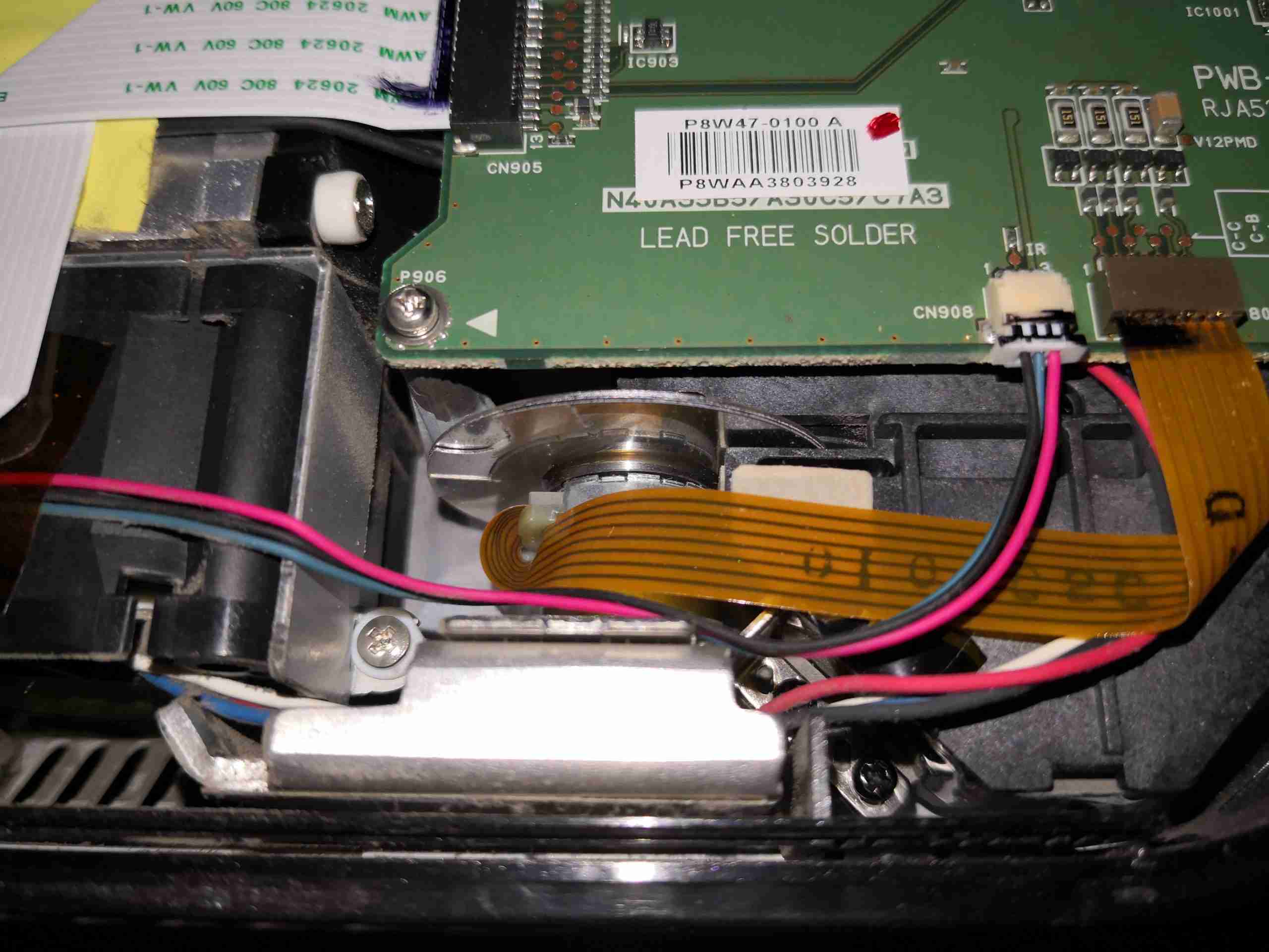
Right at the bottom edge is the connector running off to the phosphor wheel drive motor.
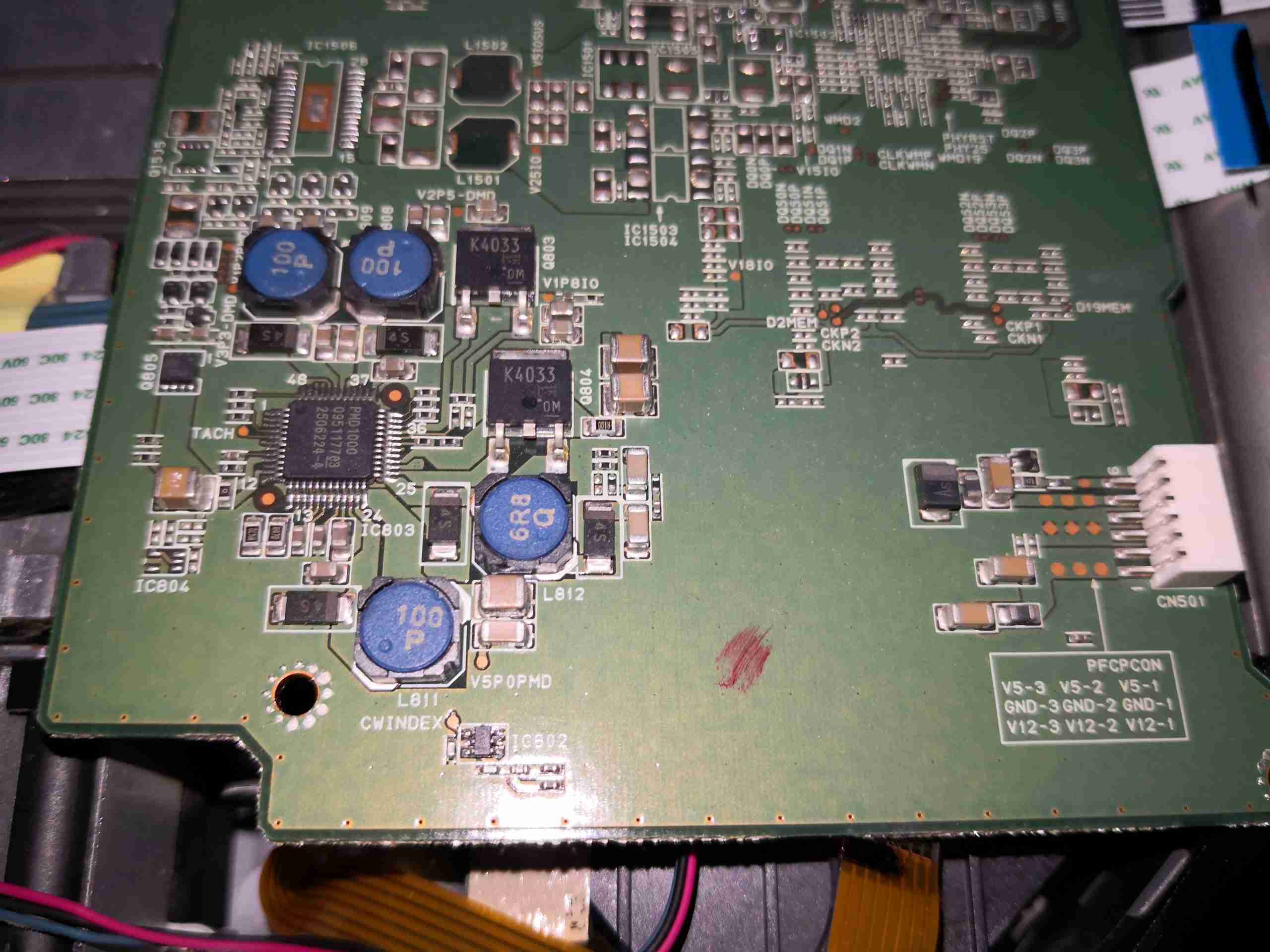
The reverse side of the board is pretty sparse, there’s quite a few passives & power control. Down towards the bottom surrounded by inductors is the system power management IC, the DLPA100. This takes the incoming DC 12v rail from the connector on the right side of the board & produces several supply rails for the internal logic: 1.1v 1.8v, 2.5v, 3.3, 5v & also contains the 3-phase brushless driver for the phosphor wheel motor. The main control board input power connector also has a +5v from the mains supply, for standby power. The main board signals the PSU to switch on the main +12v rail through a pin on this connector.
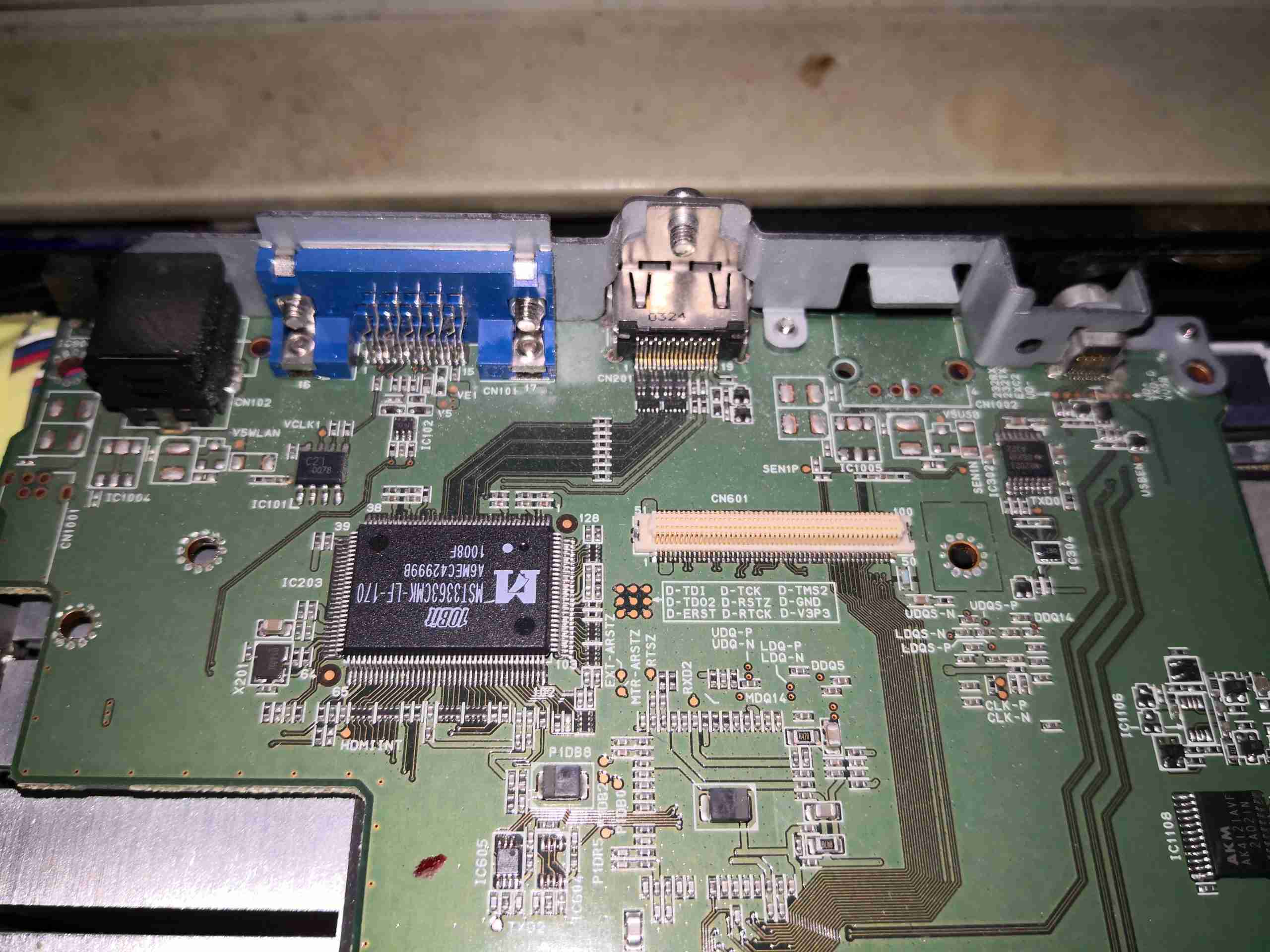
The other end of the board just has the connectors, a bit of glue logic & the HDMI interface chipset.
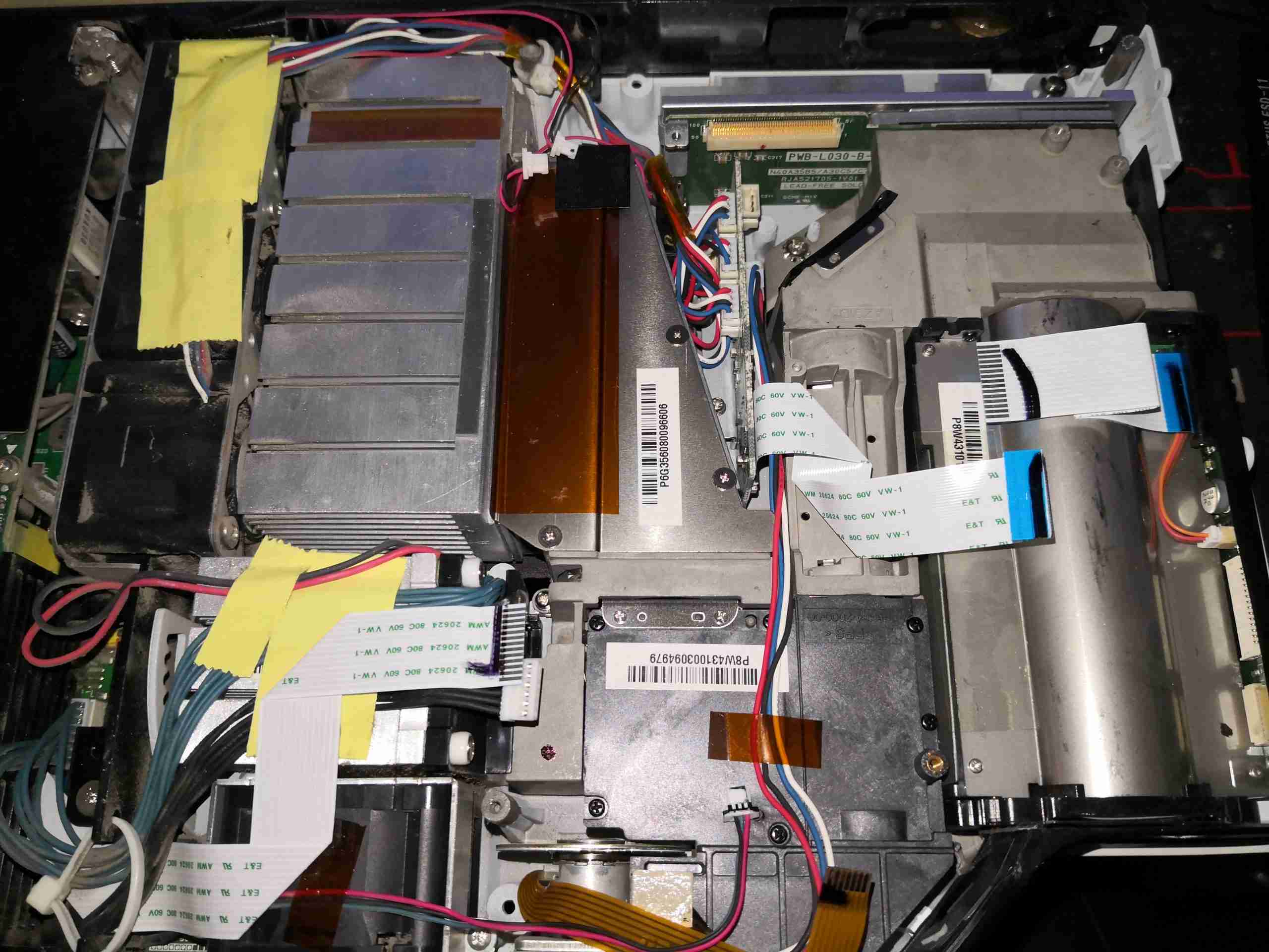
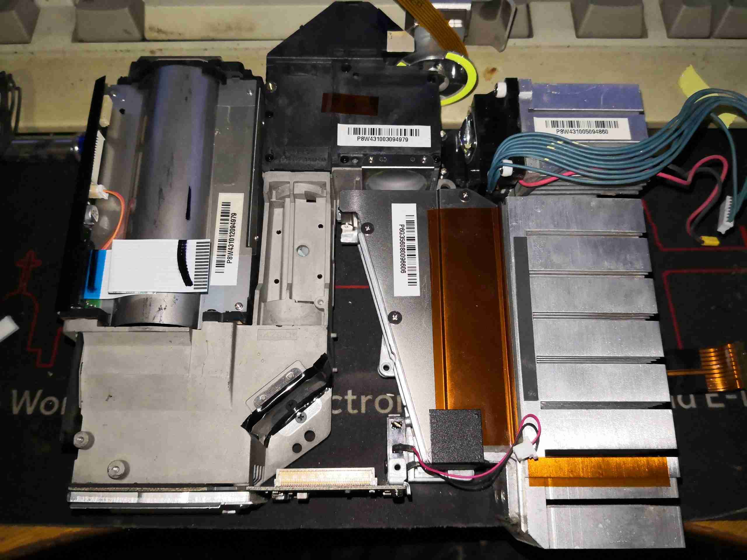
After unplugging all the connectors, the massive cast frame of the light engine is visible.
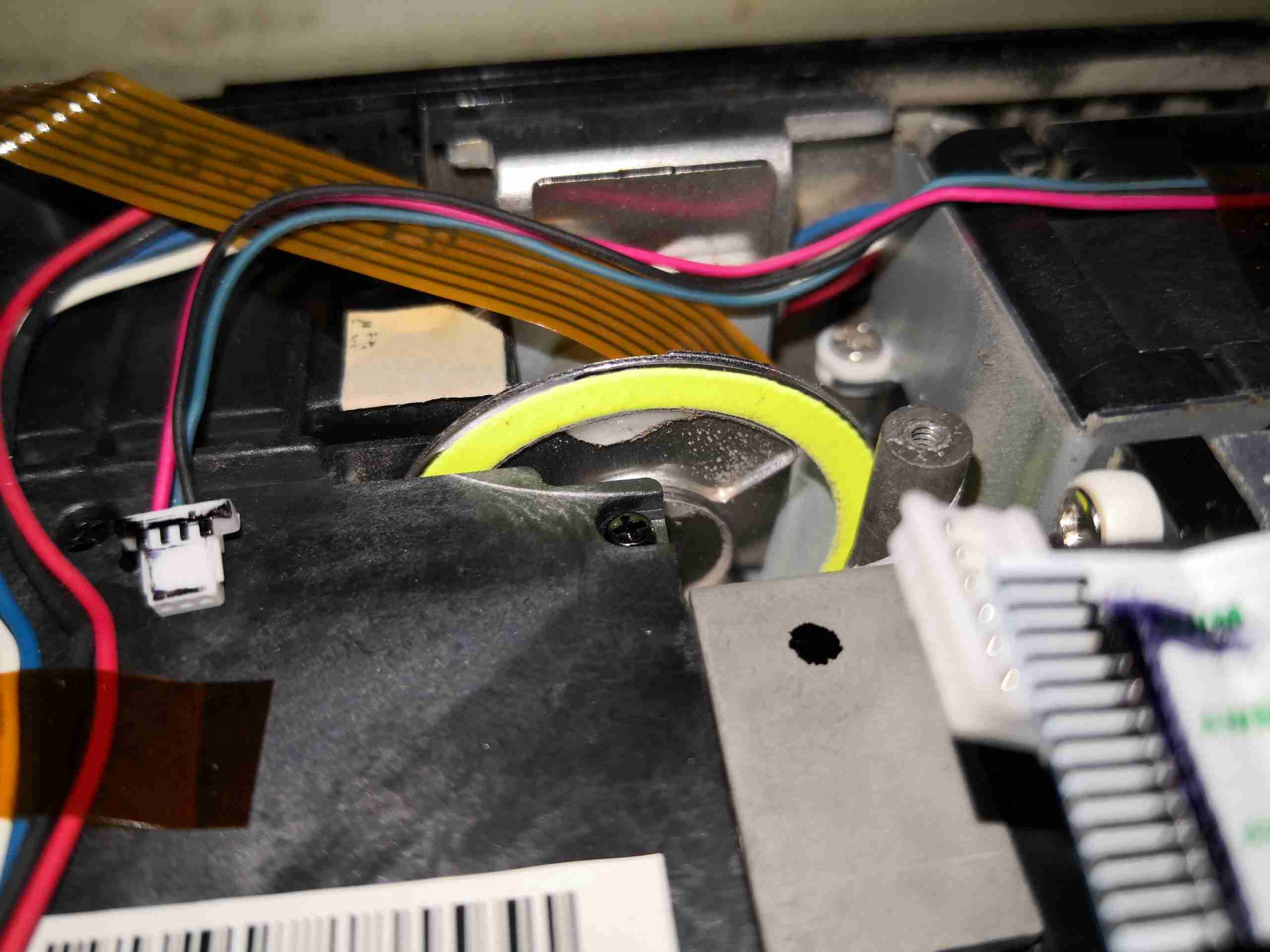
Here’s a closeup of the phosphor stripe around the edge of the wheel. This takes the 445nm light from the laser module, and converts it into green. There’s also a frosted glass section of the wheel to pass some blue for the image. The reason for the phosphor being in a large stripe on the wheel is load spreading – there’s several watts of optical power focused down to a very small spot on this phosphor, and would overheat quickly if it wasn’t moving.
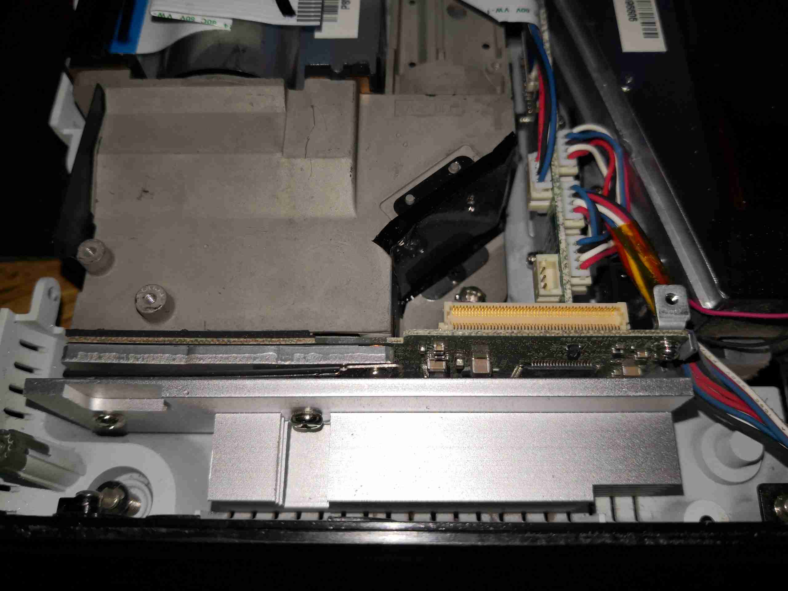
At the back of the light engine is the DLP module, with it’s substantial heatsink.
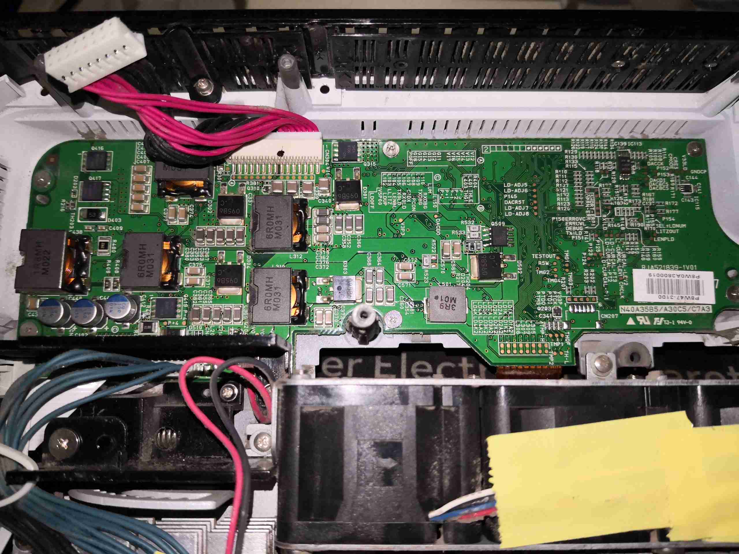
Hiding under the mains PSU, is the light source control PCB. This contains several DC-DC converters, which run the 4 strings of laser diodes, the large Phlatlight Red LED & it’s associated TEC cooler. This board takes the incoming +12v from the mains PSU through the multi-way loom at top centre. There are multiple cores on this connector to spread the load – at normal brightness, in Eco mode, I measured the power consumption at about 8.5A at 12v input for the entire projector.
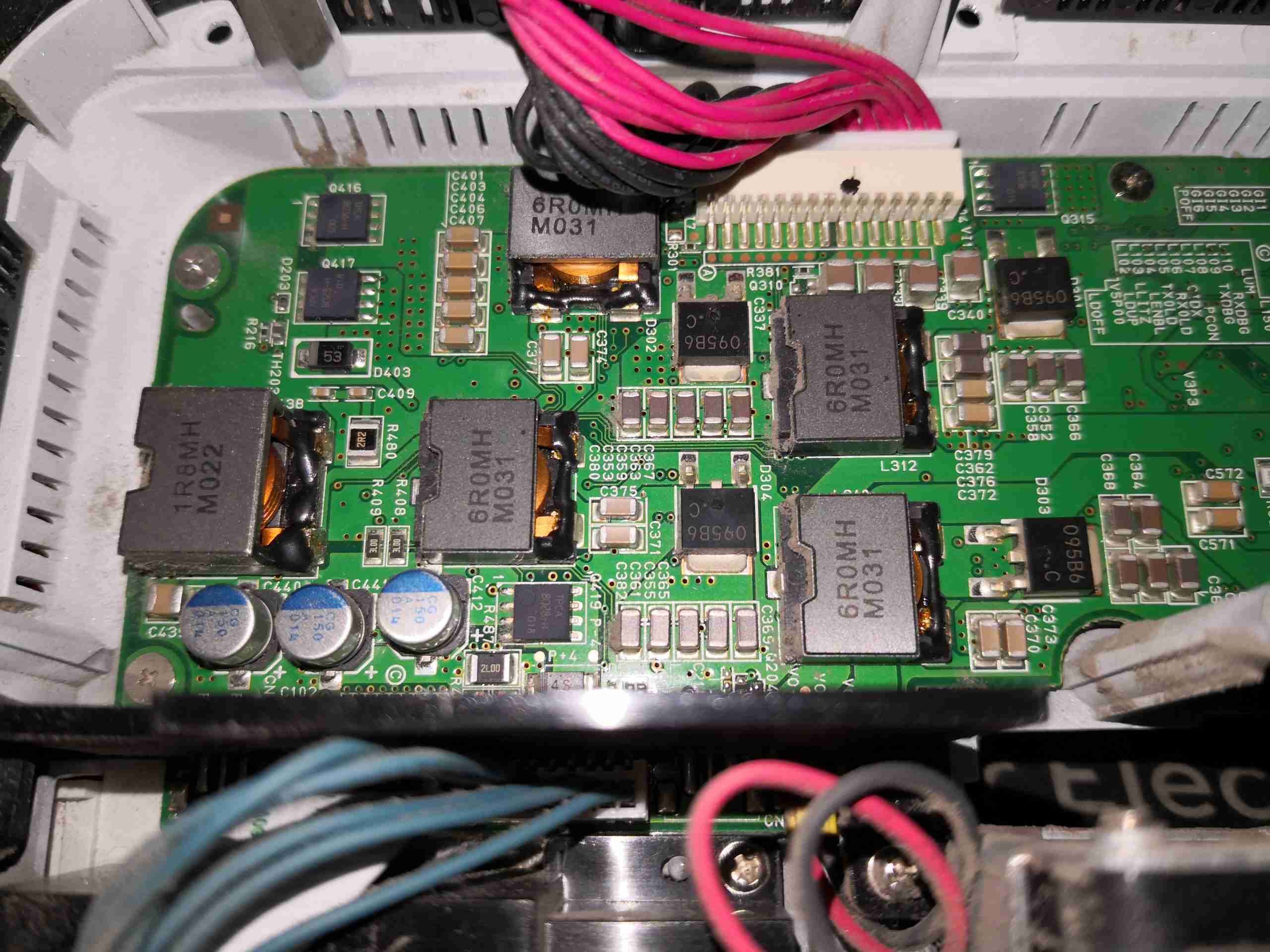
The left side of the board is dedicated to the high power section of the controller. There’s a power inductor for every channel.
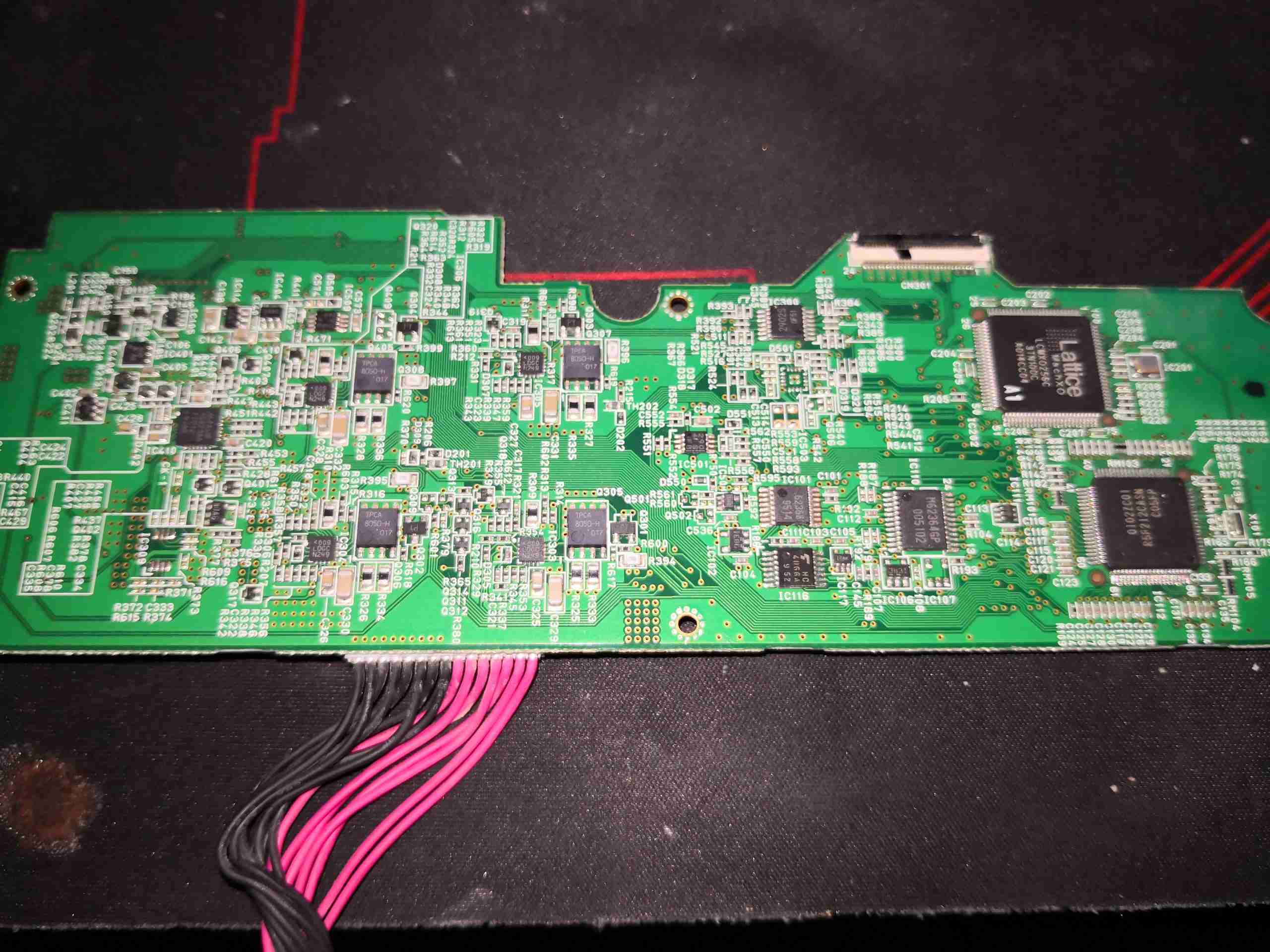
The other side of the board is very heavily populated with components.
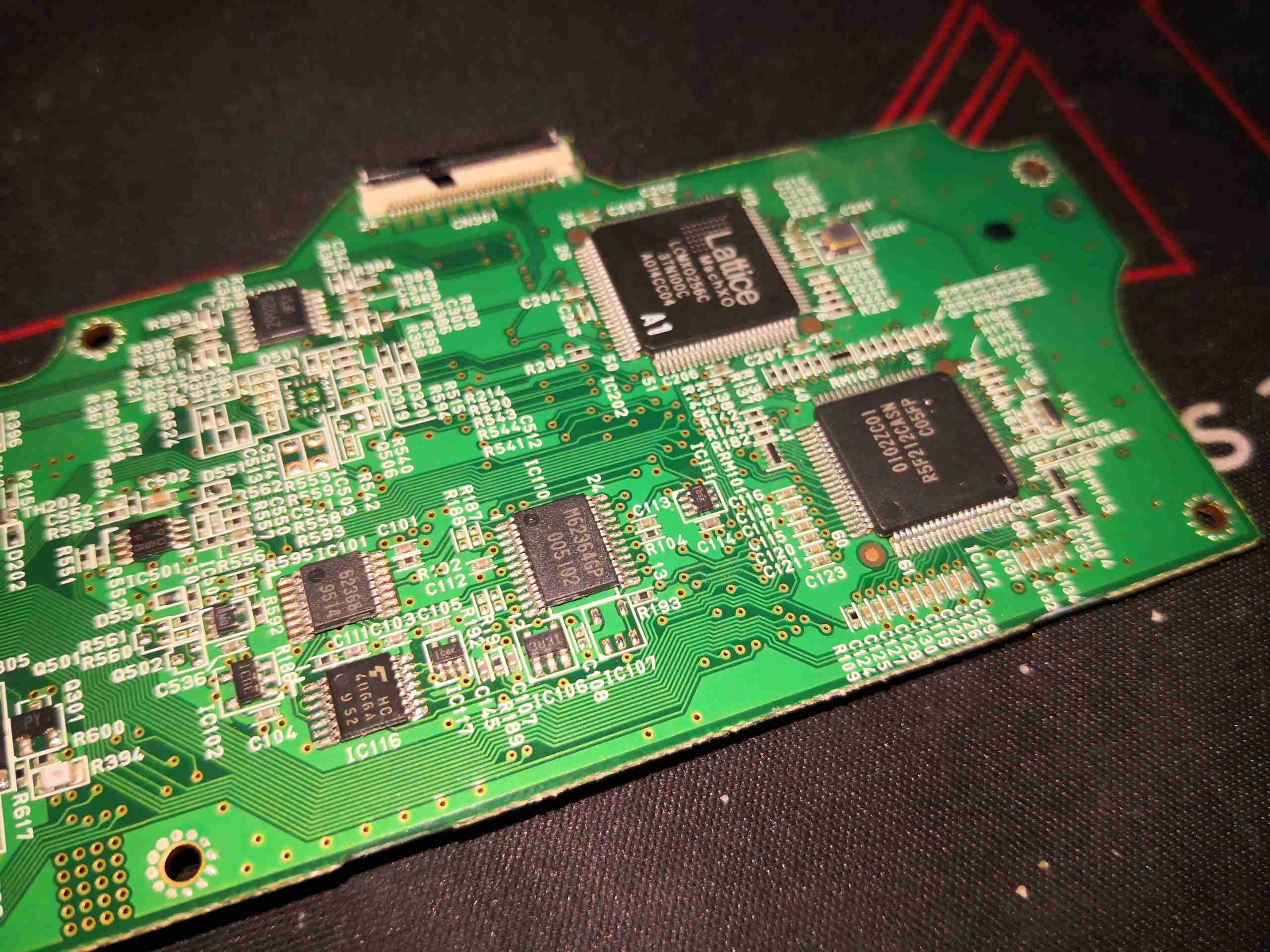
The right hand side has the control logic, a Lattice CPLD, and another Renesas Microcontroller. There’s also some glue logic here & a dedicated DA converter.
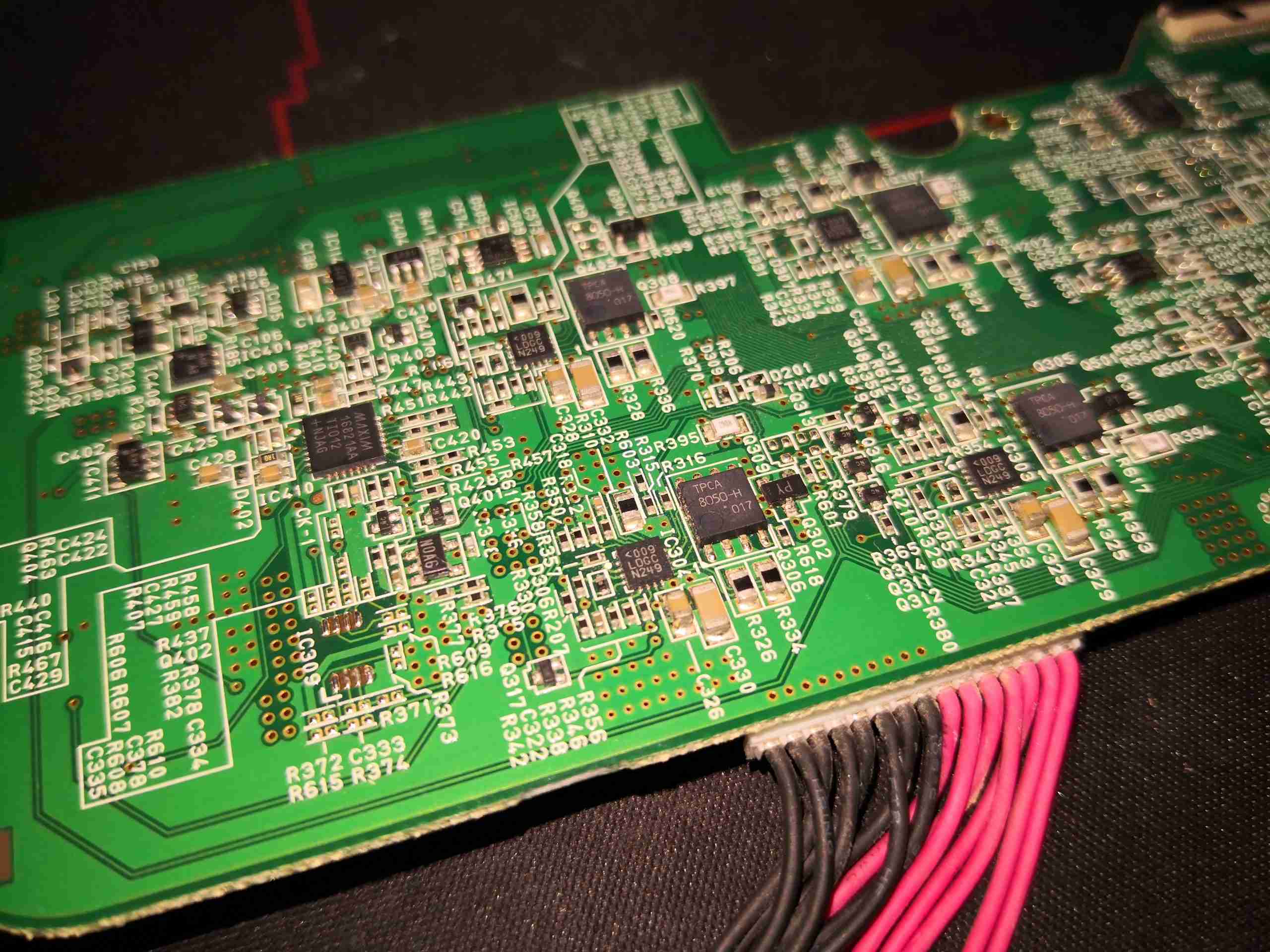
The other end of the board has the power drive control logic. There’s a MAX16821AA LED buck driver for the Red LED, and 4 drive ICs for the laser diodes, which are marked <009 LDGC N249. I haven’t been able to find anything about these, so they may be custom.
Removing some screws allows the entire optical assembly to be removed from the lower shell. This may be mostly manufactured from a magnesium alloy from the rather low weight.
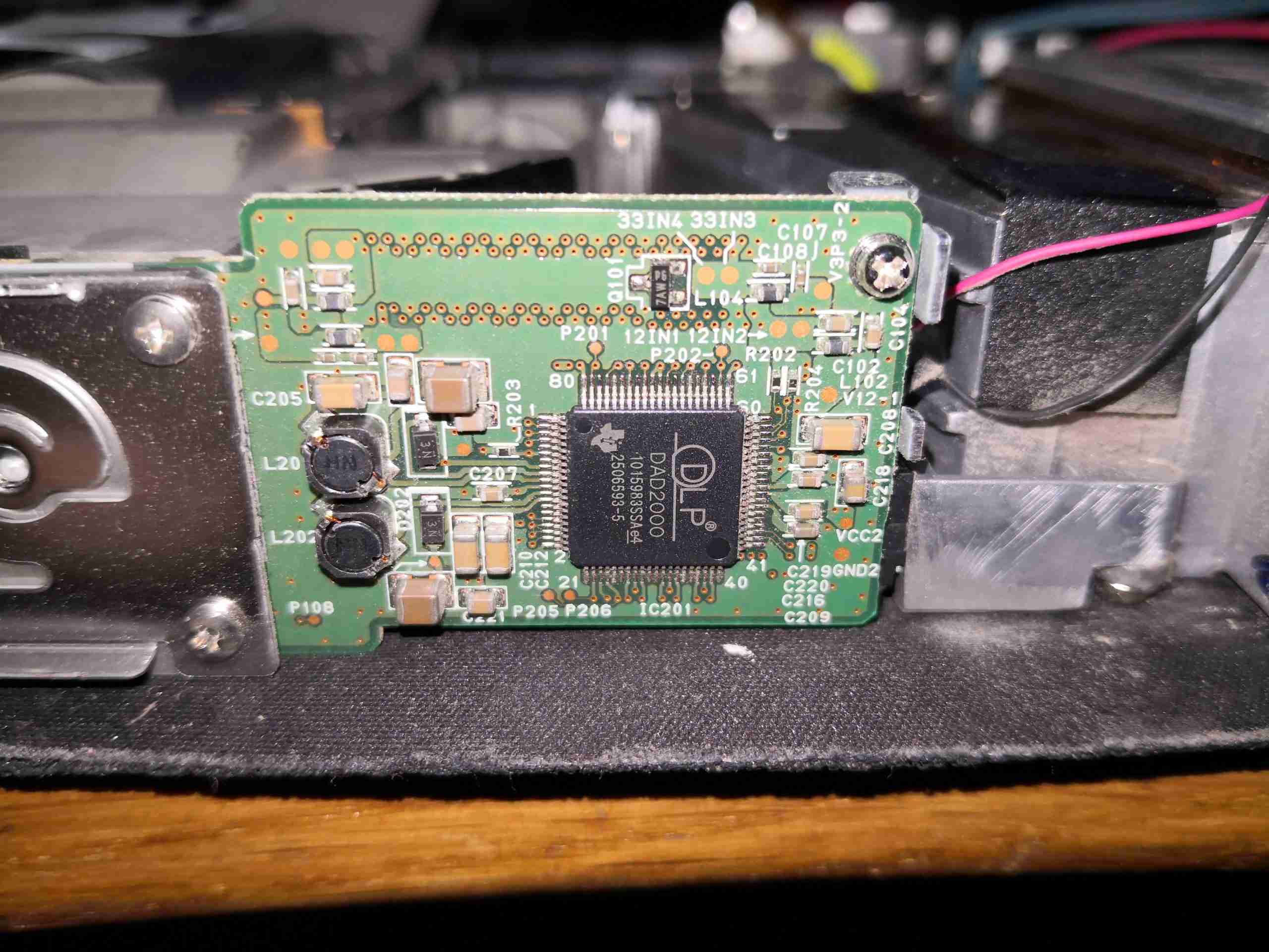
On the back of the DLP module is the DLPA200 Micromirror Driver IC. This generates the high voltage bias supplies for the DMD chip (+/-28v) from the 12v rail, generates all the timing waveforms required for the DLP chip. There’s a couple of power inductors for the onboard regulators. Video data is sent from the main image processing chipset to the DMD chip via 2 channels of LVDS.
Now the heatsink has been removed, the rear of the DLP chip can be seen, with the remains of the thermal pad. The mount for the heatsink is sprung, to accommodate thermal expansion.
The Red light required to create a colour image is generated by a giant LED, more on this one later.
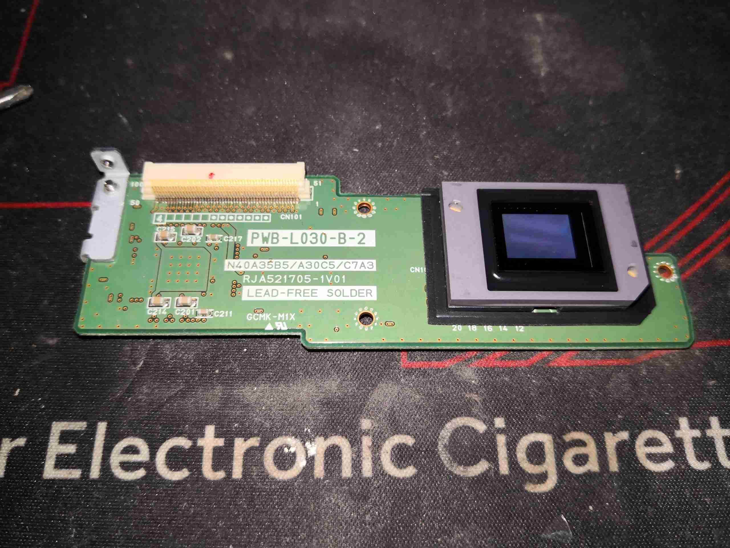
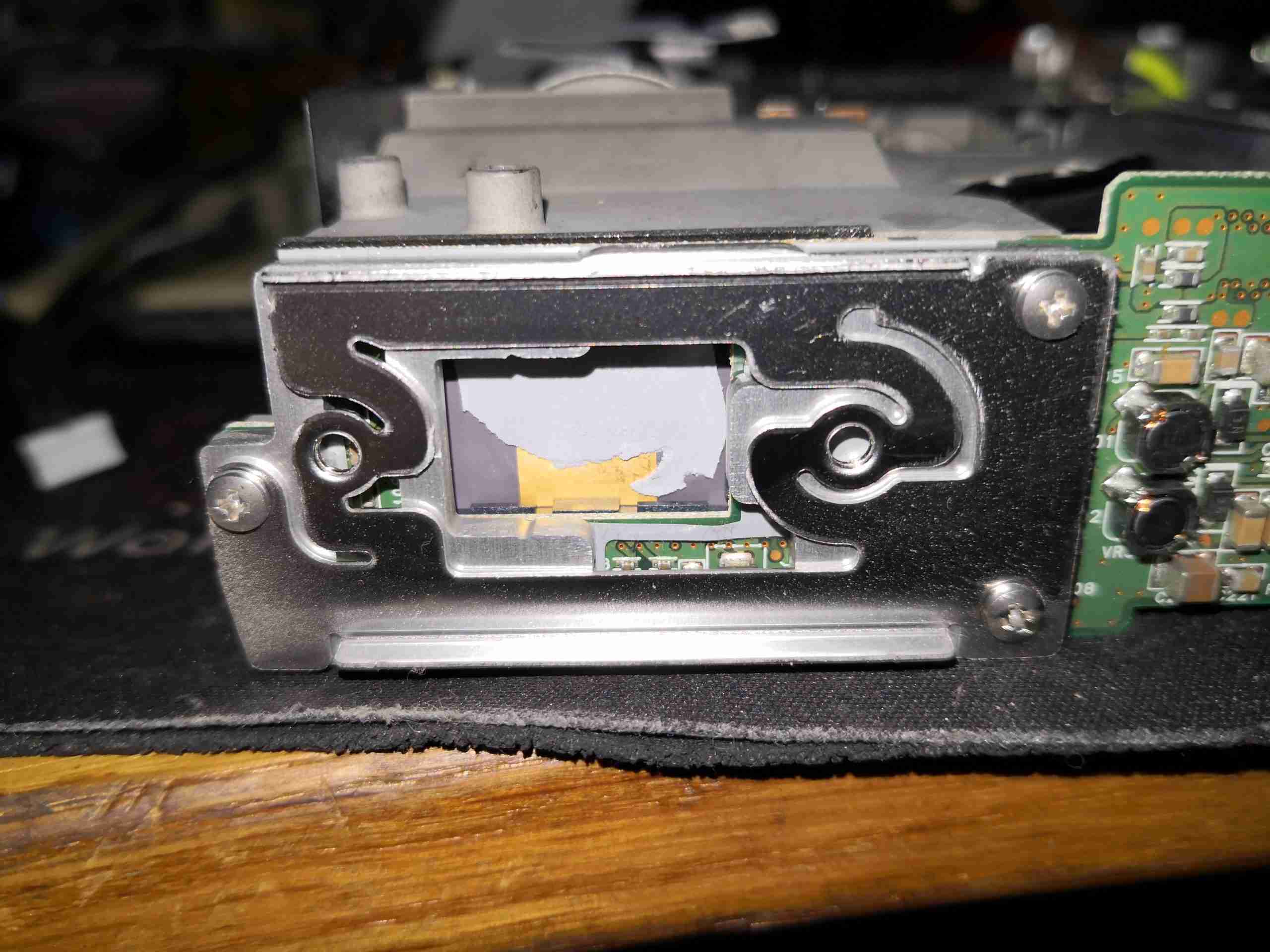
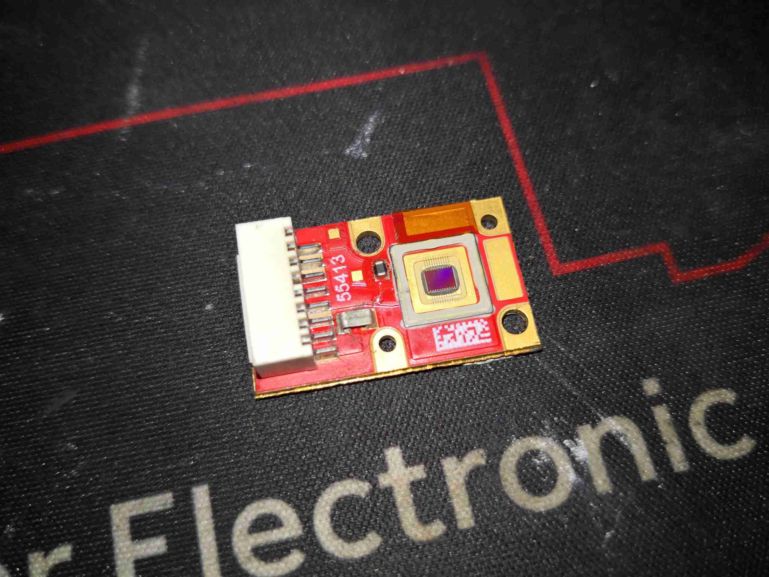
Here’s the DLP board removed from the projector with the micromirror surface visible. This DLP has many dead pixels, hence the decommission at ~4500 hours of operation.
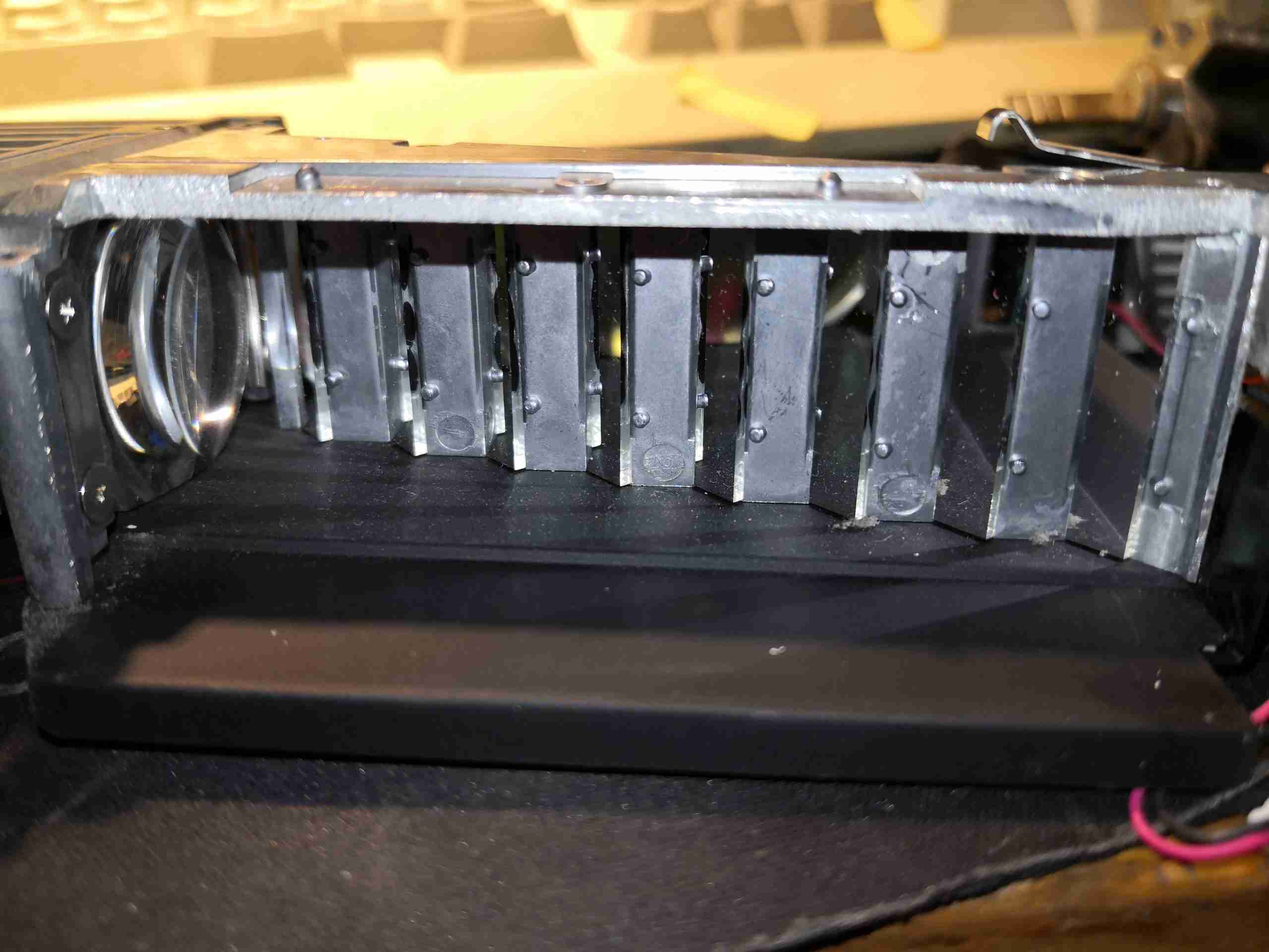
The 24 laser diodes have their beams combined by this knife-edge mirror assembly, turning the beam through 90° to the lens on the left, which focuses the 24 beams down to the optics engine.
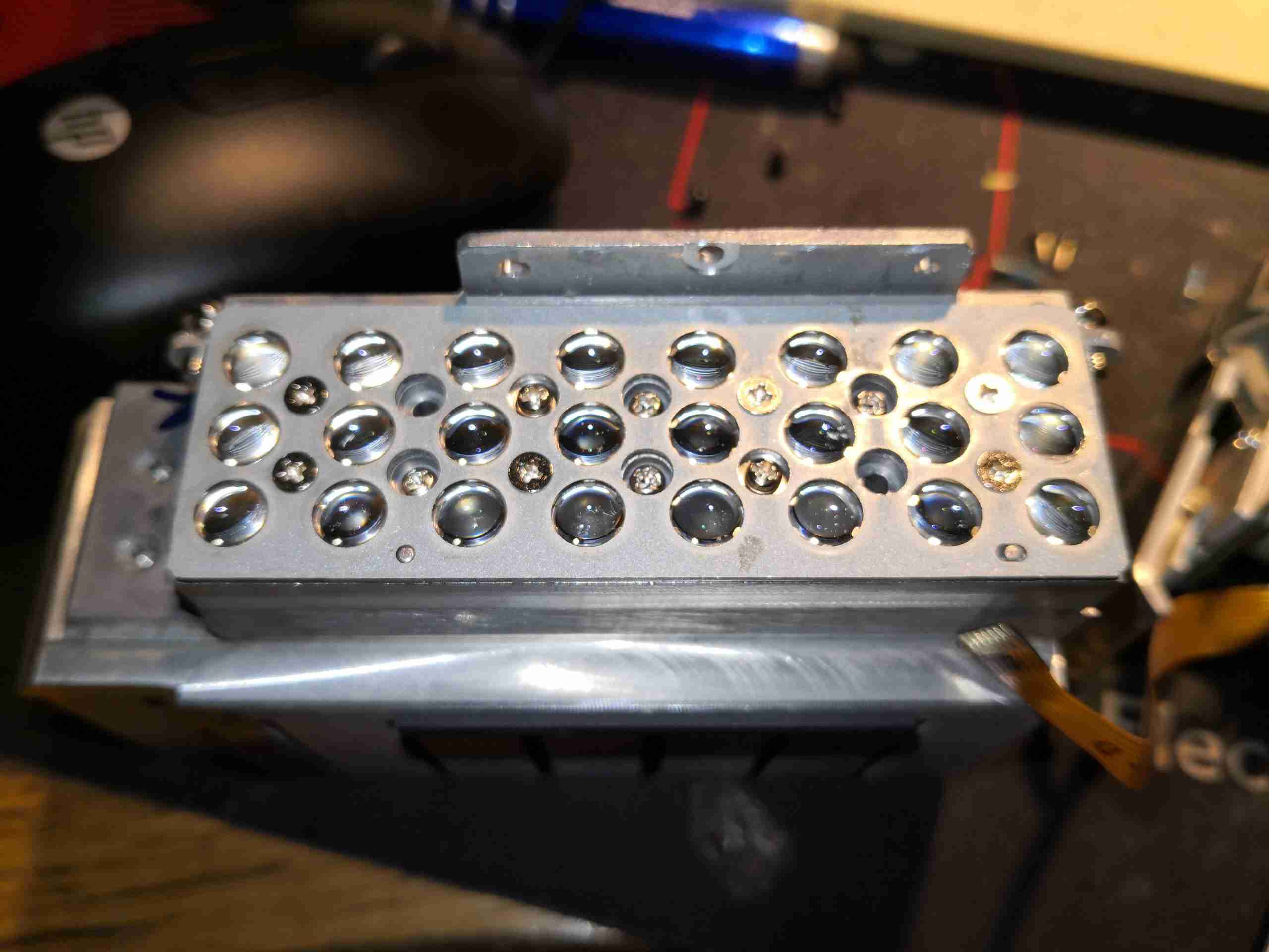
Removing the beam combiner from the array allows the 24 diodes to be seen, mounted under their collimating lenses. This is one beast of a laser unit!
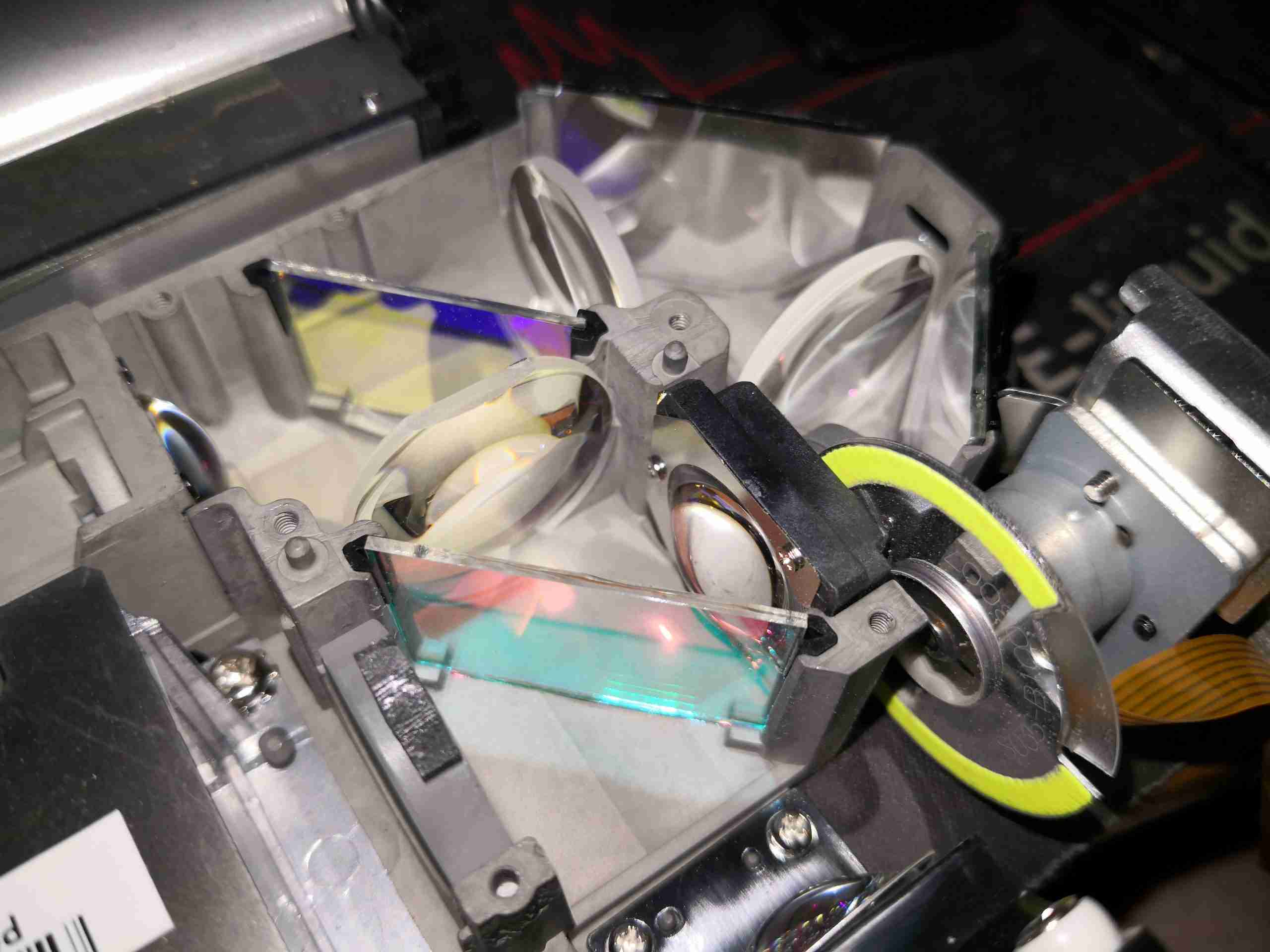
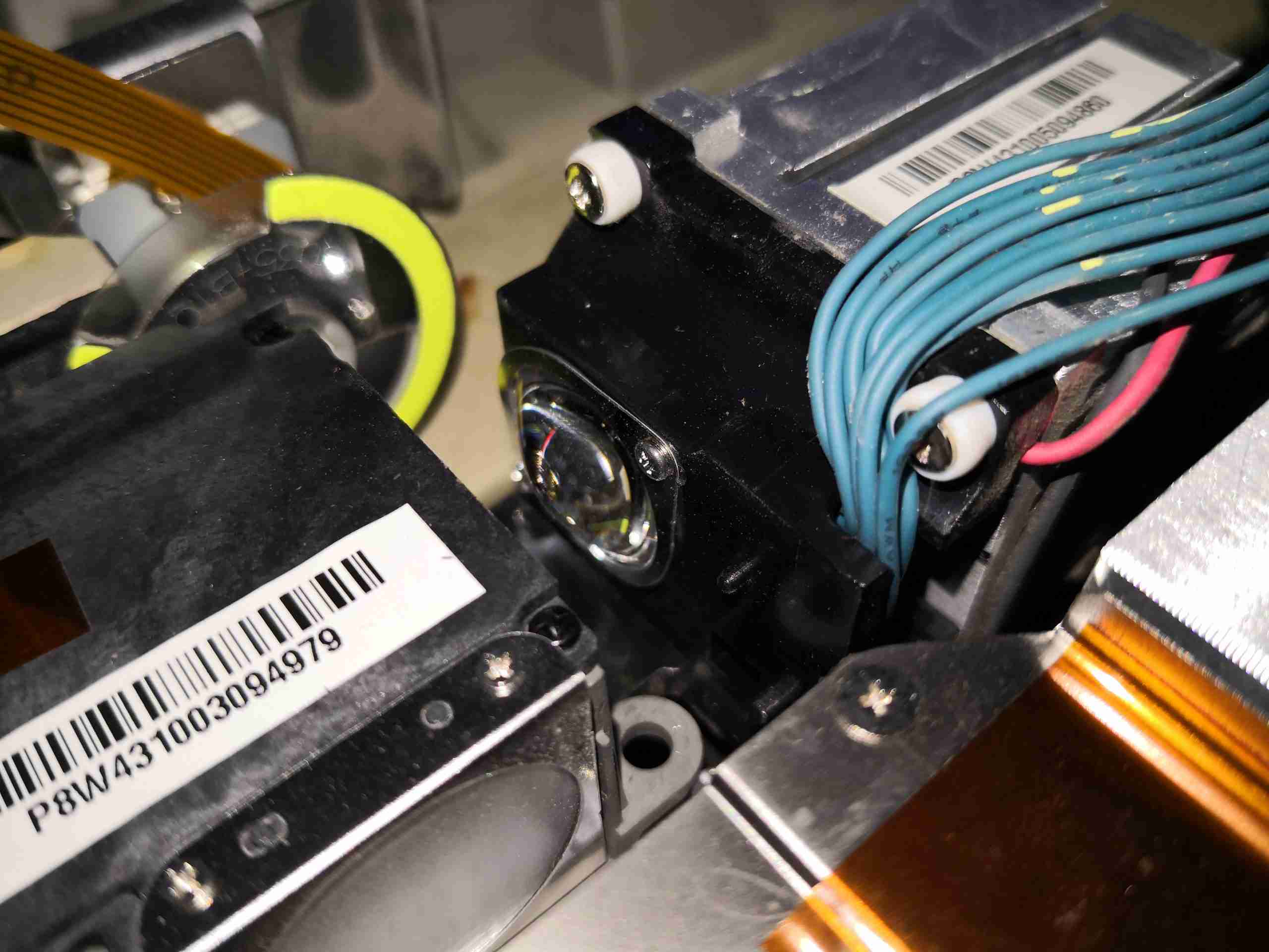
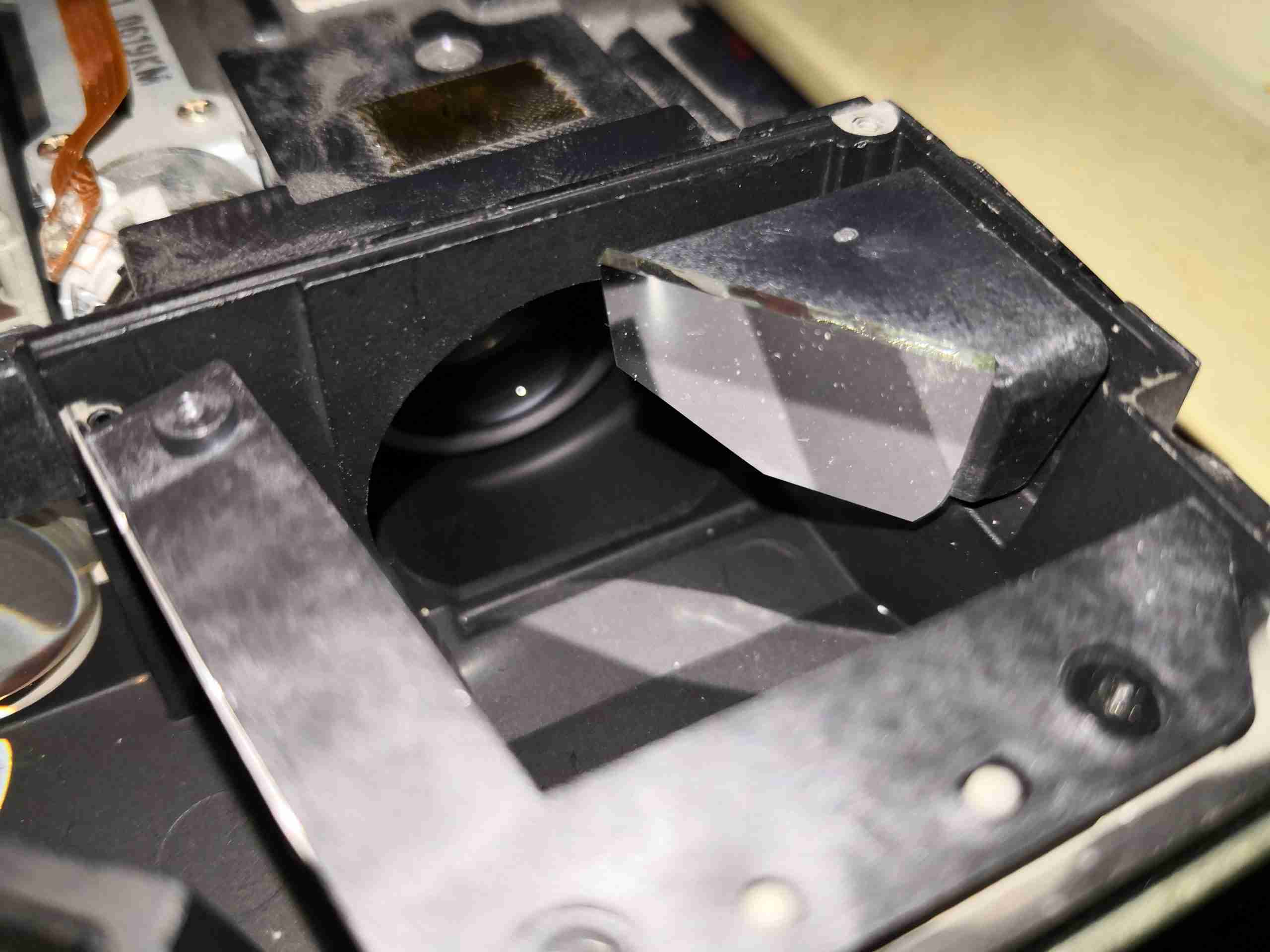
Taking the cover off the optics assembly allows the main optical path to be seen. The blue laser comes in a bottom left, through the lens, the red LED comes in bottom right. The pair of dichroic mirrors manage the light path for the red & green light, while passing the blue straight through.
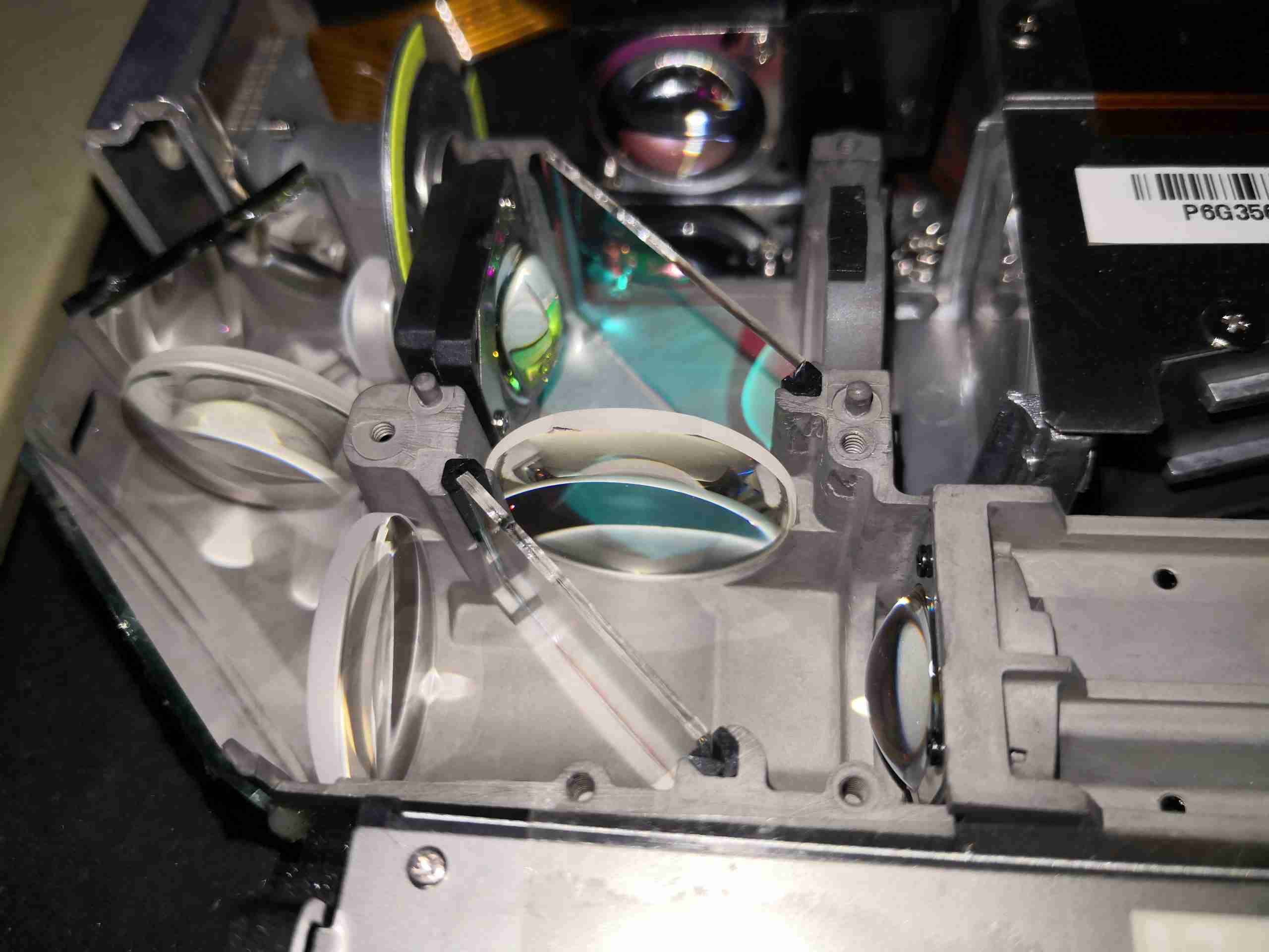
Here’s another view of the optical path, with both light sources visible.
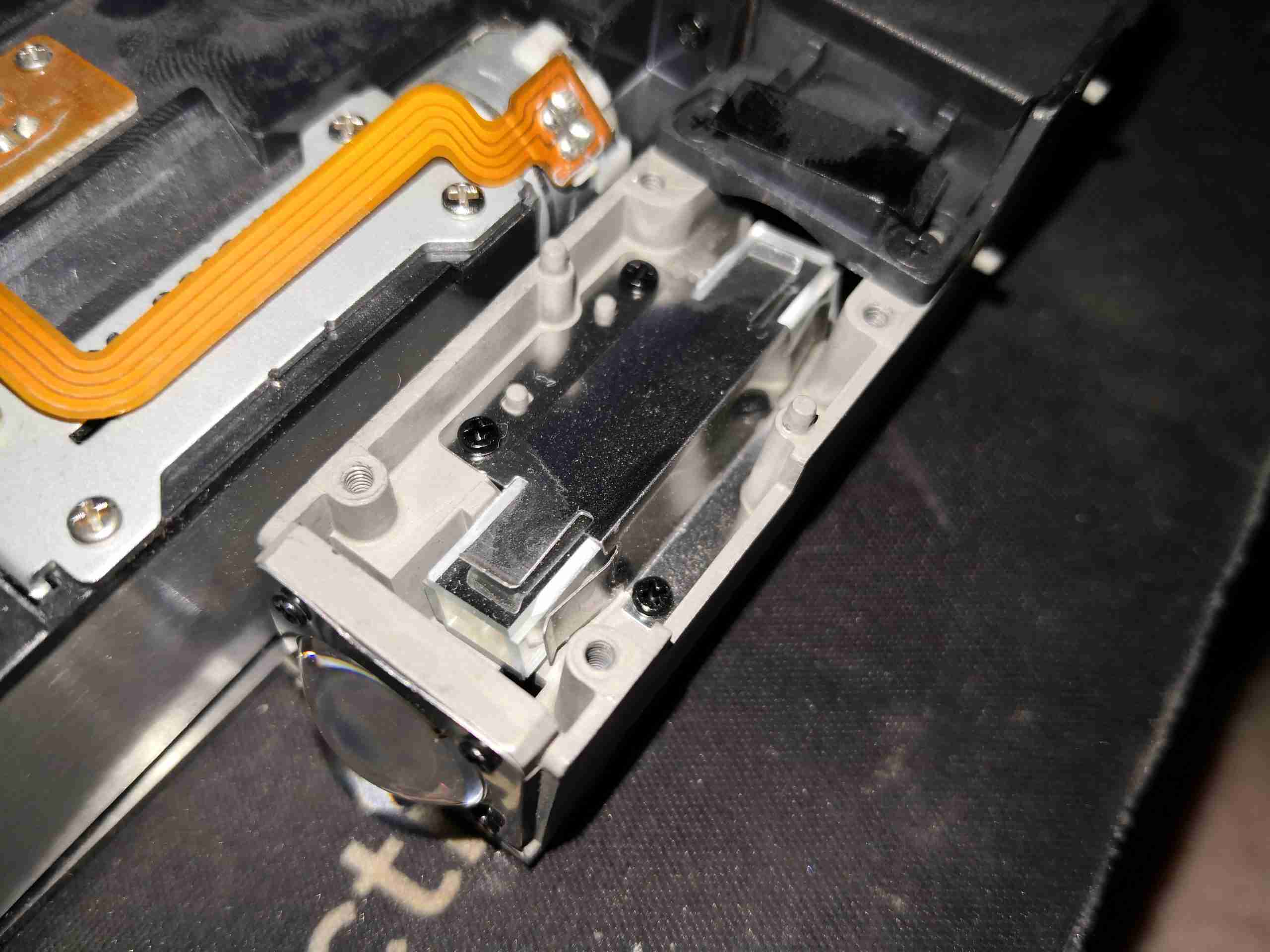
After the light source, is the homogeniser – this tunnel of 4 mirrors facing each other evens out the light beam & removes all coherence from the laser light. This is important to not have any speckle in the image.
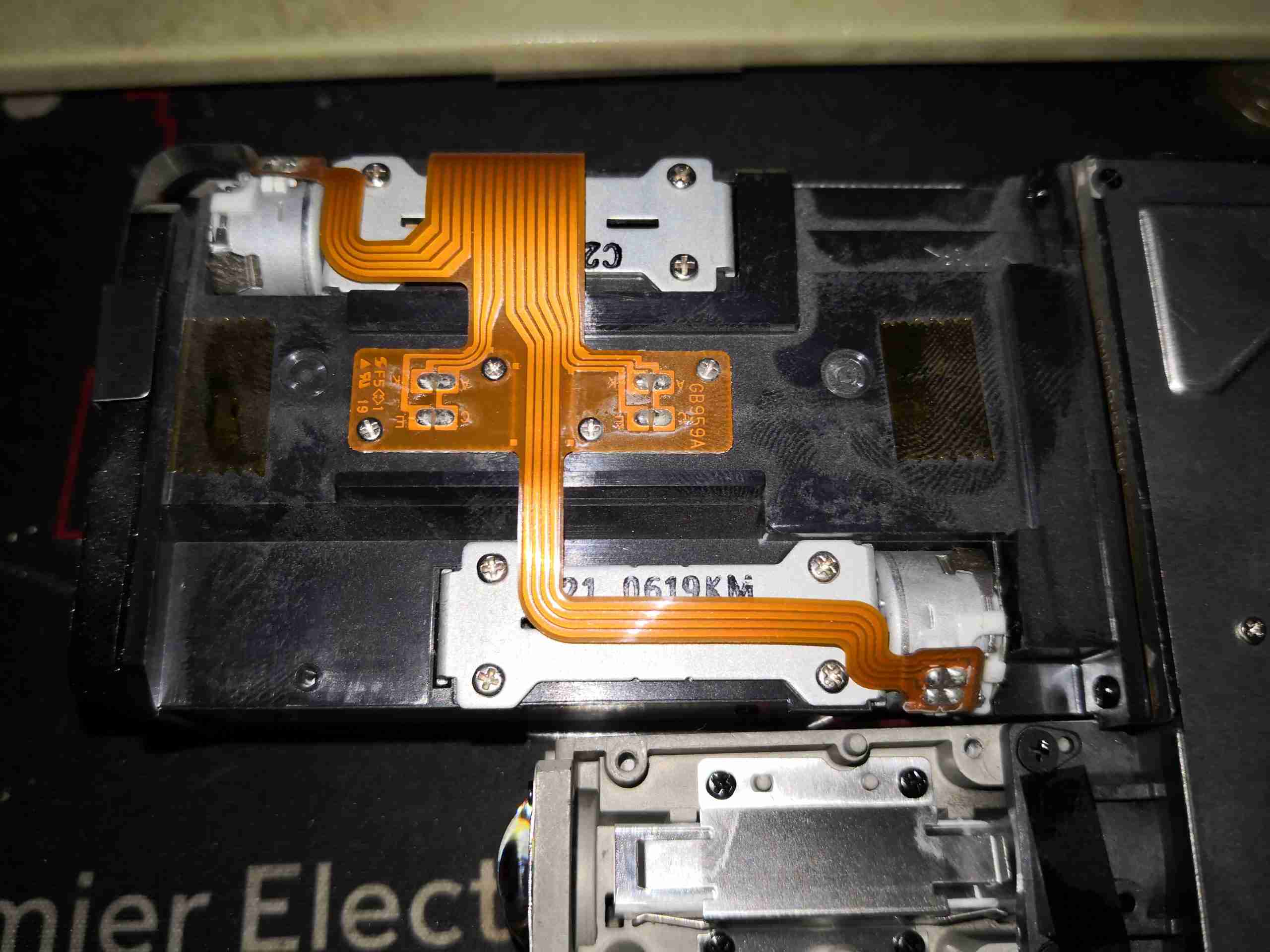
Underneath the objective lens are the pair of stepper motors that drive the focus & zoom mechanisms, along with their position sensors.
Just after the homogeniser, is the final optical path to the DLP. Here the light comes in a bottom left, and hits the turning mirror, after which it is focused onto the DLP chip by the mirror top centre. The objective lens is through the hole in the centre of the optical block, while the DLP is on the right side.
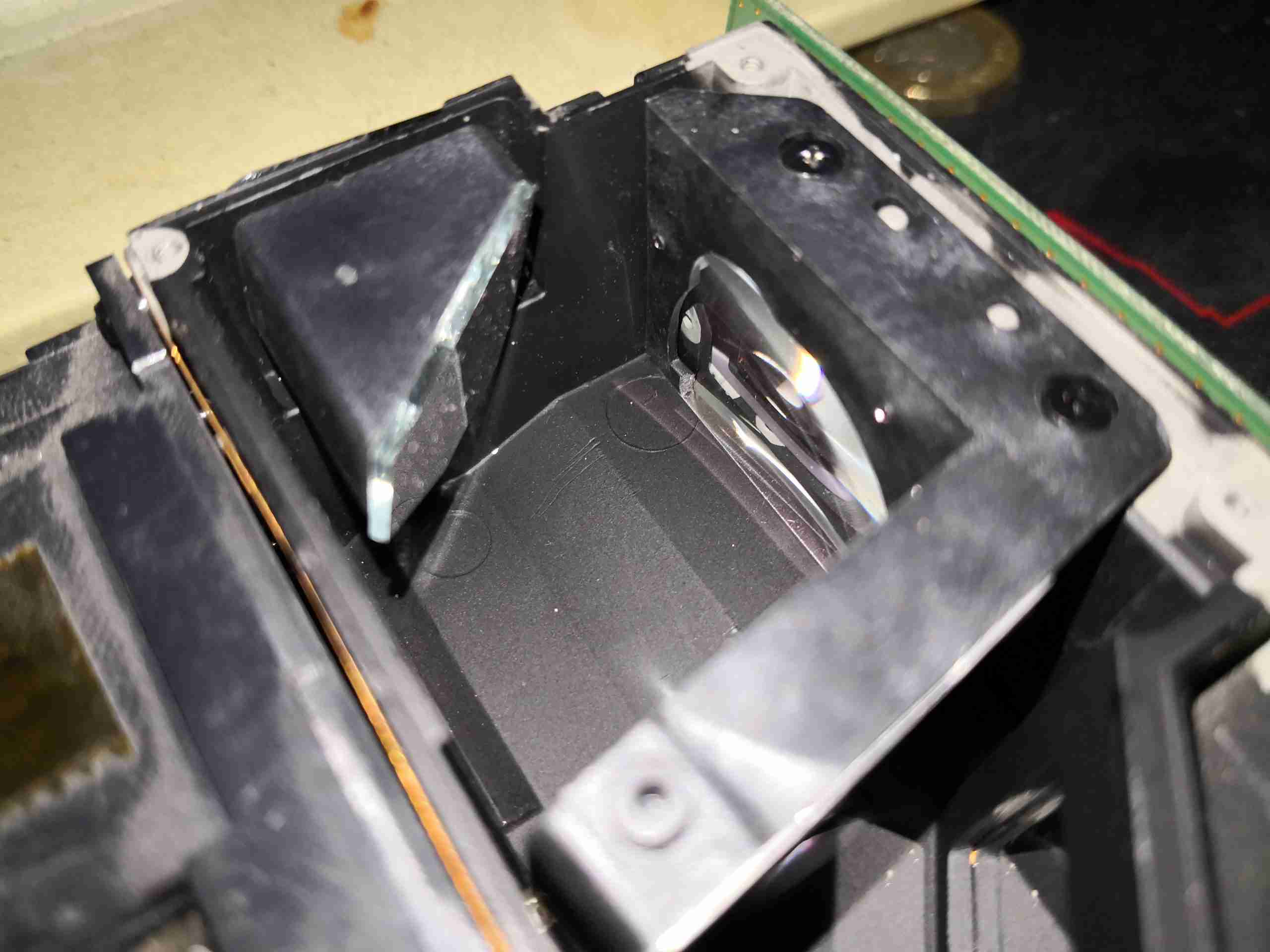
Here’s where the DLP will be mounted in normal operation, with it’s lens in place.
Finally, the created image is passed out through the objective lens to the projection screen.
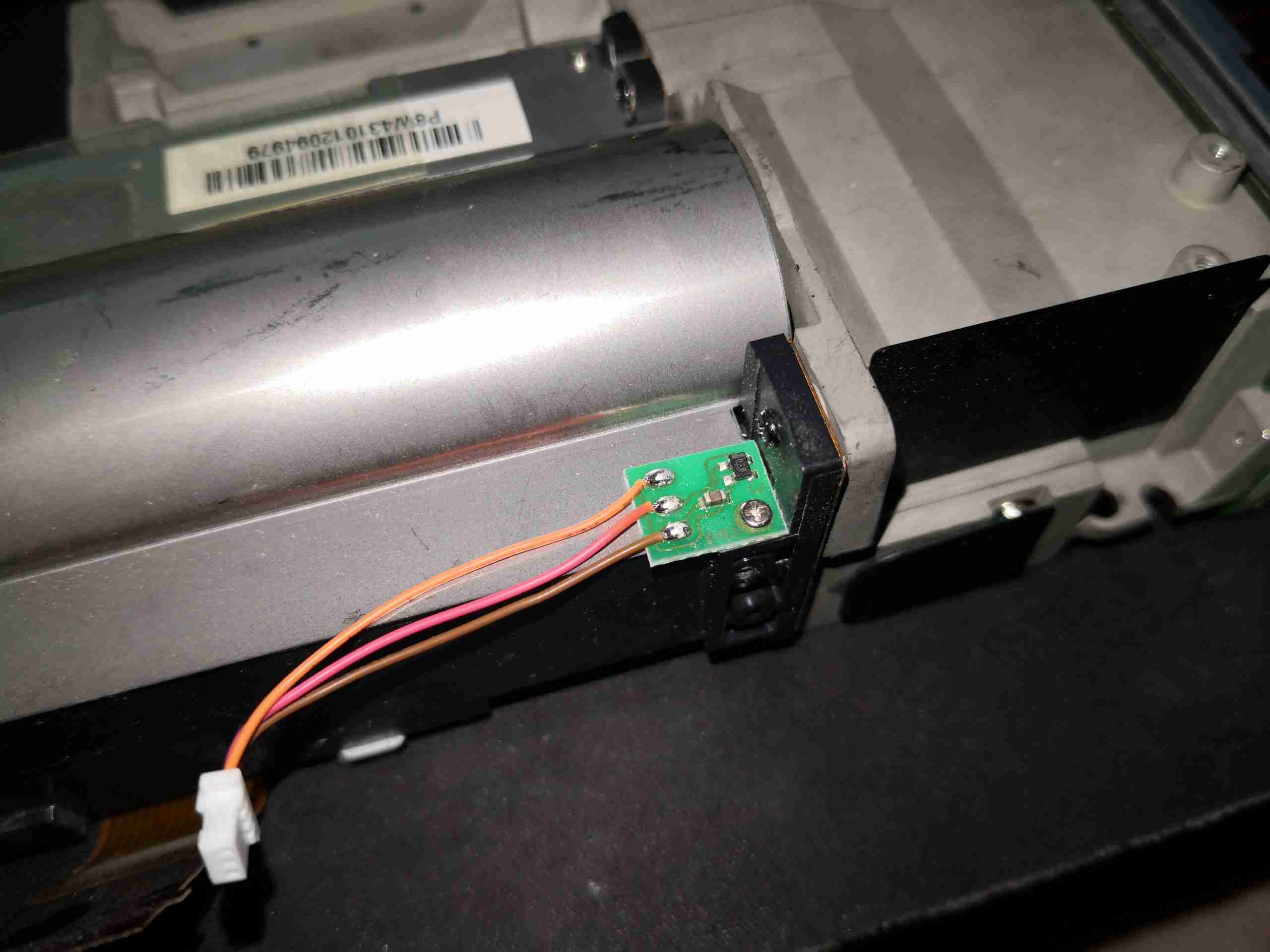
There’s a sensor mounted on the side of the lens barrel, that I think is a Hall effect device, but I’m unsure what this would be used for, as there is no magnet anywhere near this to sense. It could also be a temperature sensor though, for the DLP & lens assembly.
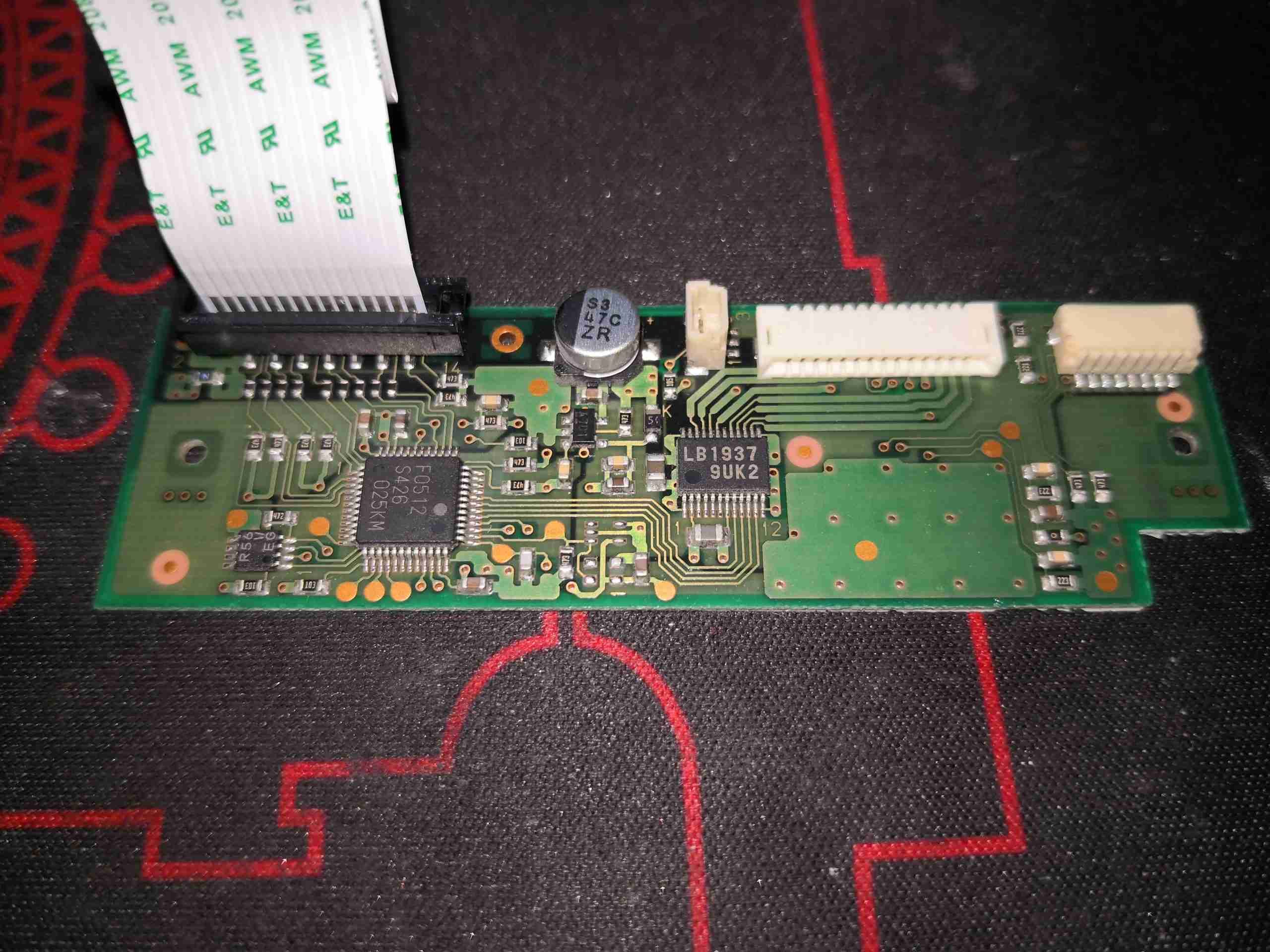
The small PCB on the side of the lens unit holds the stepper motor drive IC, an LB1937 from Sanyo. There is another IC here, which looks to be a microcontroller.
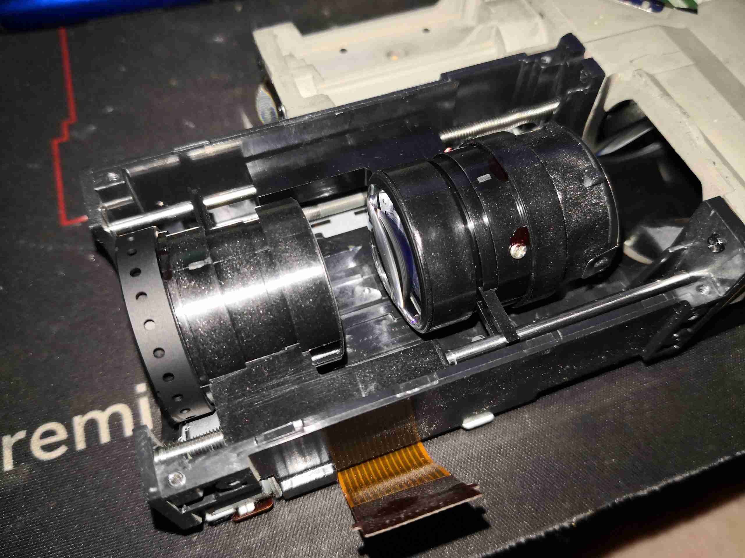
Removing the top cover allows the moving lens assemblies to be seen. These move independently of each other to implement focus & zoom, via lead screw drives on the stepper motors.
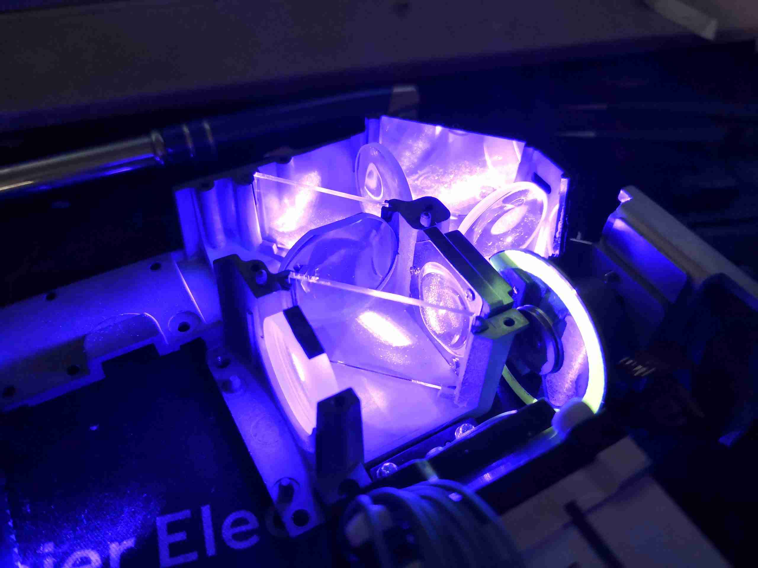
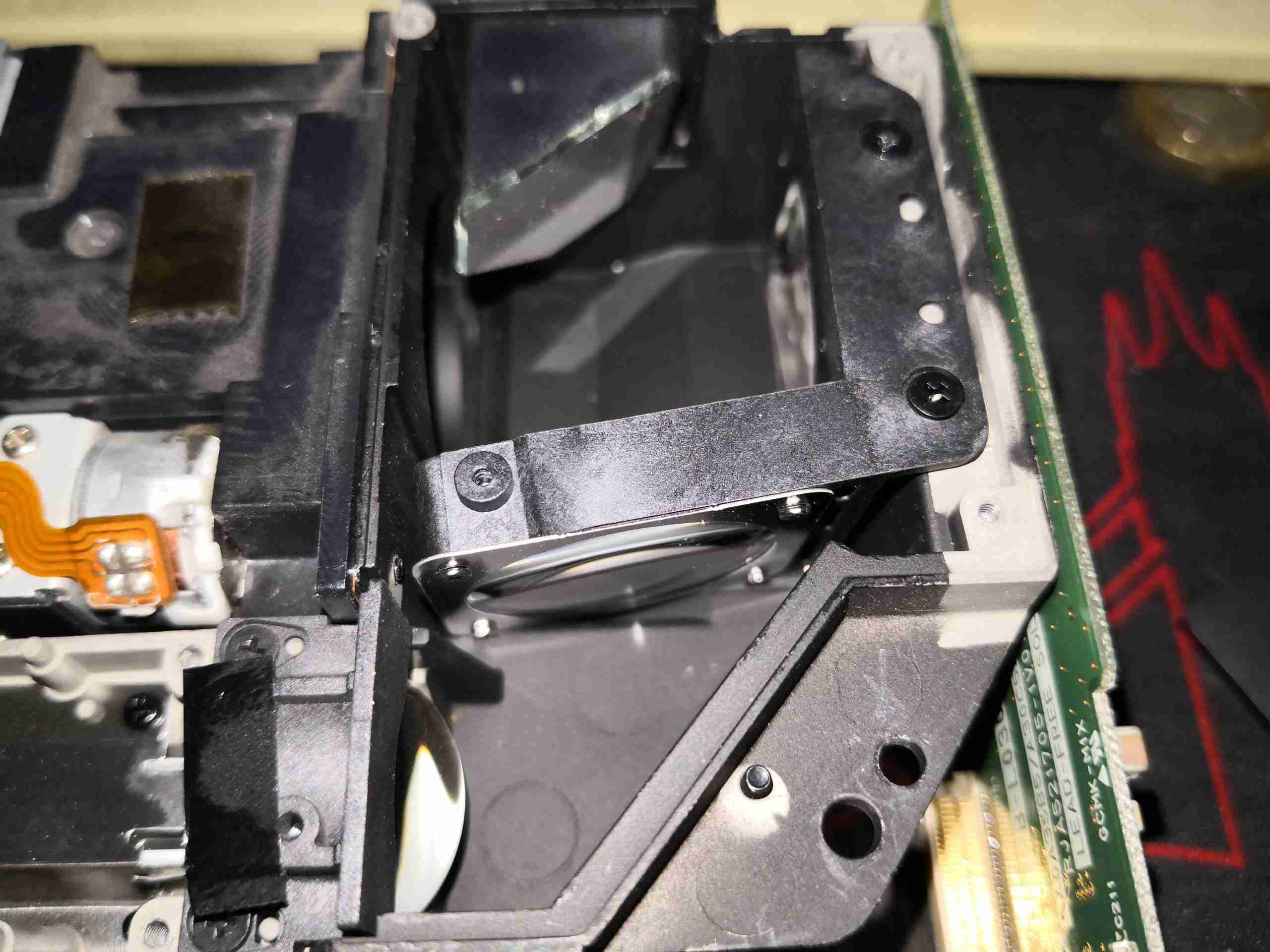
Here I’m shining a separate 445nm diode laser into the optical assembly, through the blue optical path. The phosphor wheel is turned to the clear section, which allows the 445nm light to pass straight through, being turned 180° by the mirrors & directed out towards where the DLP assembly would be.
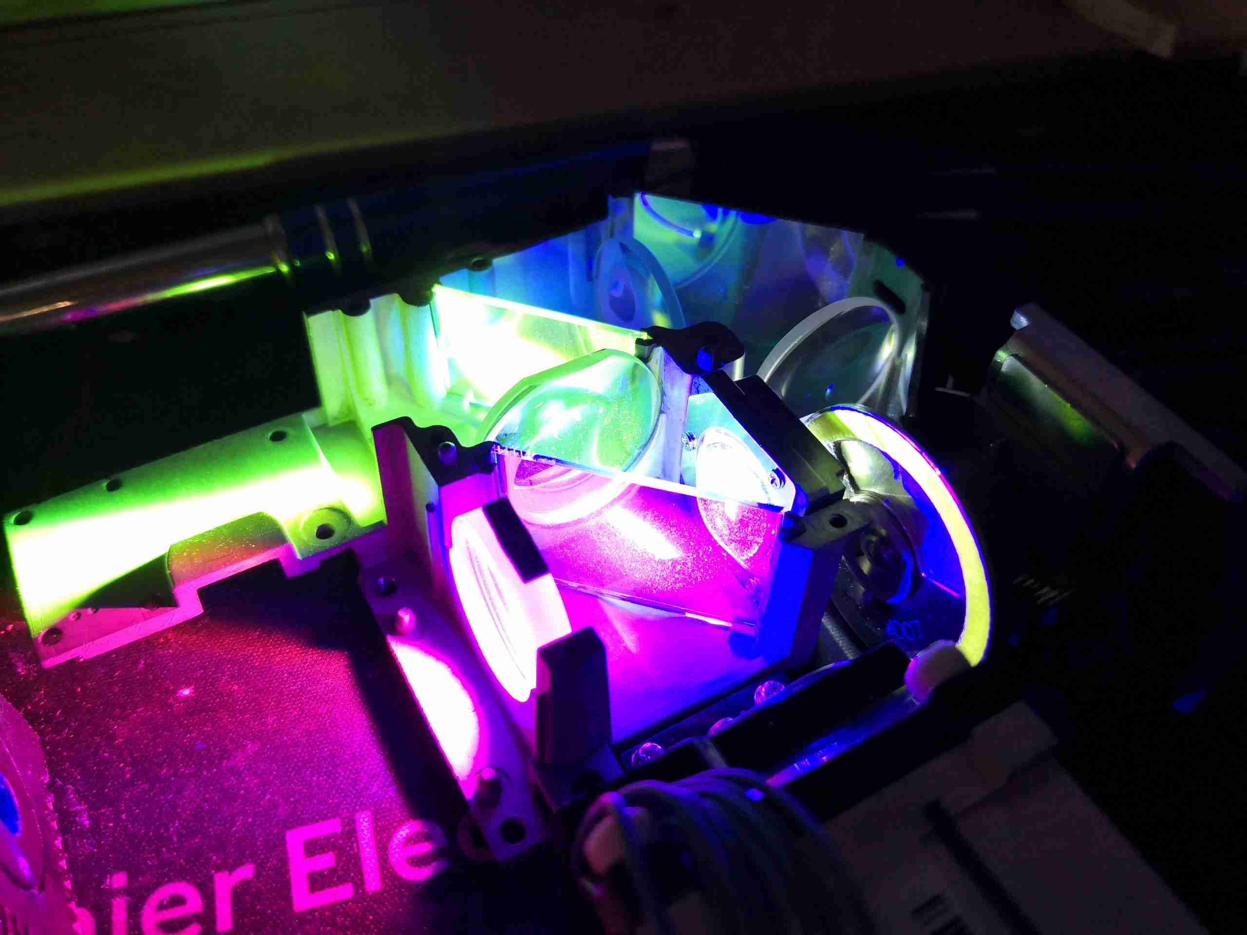
Turning the phosphor into the light path causes a very bright green light to be generated, and passed back towards the 445nm laser entry point. The dichroic mirror in the way reflects this light to the left, through a lens & then to the other dichroic mirror to be turned another 90° to the DLP assembly. I’m not sure where the magenta light is coming from – the phosphor probably generates light on more wavelengths than just pur green, giving some red to mix with the blue.
Here’s the Red LED removed from it’s cooling & collimation assembly – this has an enormous silicon emitter area, and apparently these LEDs are designed to be uniform in light emission, specially made for projection use. There’s a thermistor onboard for temperature sensing – sensible when the datasheet gives CW currents of 8A, and pulsed currents of 13.5A!
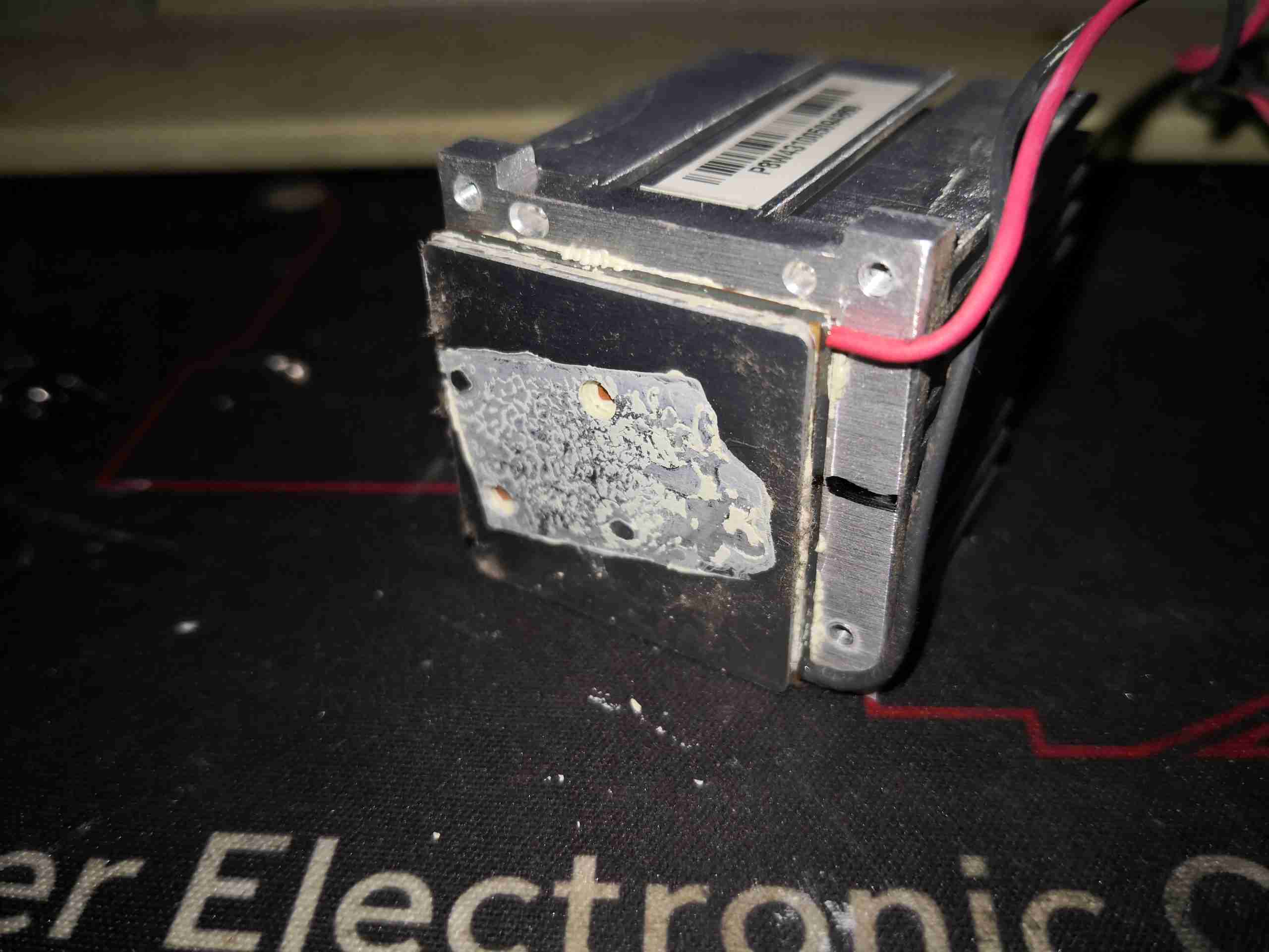
Not surprisingly, cooling this beast of an LED requires more than just a heatsink, so it’s mounted on a TEC module, possibly around 40W thermal capacity.
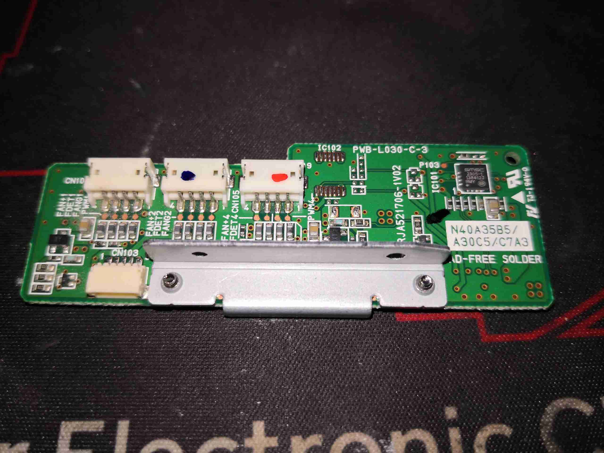
Fan control is handled by this little PCB, squeezed in between the optics engine & 445nm Laser array. There’s a SMSC EMC2305 I²C 5-channel PWM fan controller on here, communicating back to the main system microcontroller. Besides some passives, and 4 transistors to make sure the fans don’t start at full power when the projector is powered on, there’s not much else.

Hi, I was wondering how all the laser drivers can be utilised without all the control circuitry. I got this purely for the laser array but I’m not sure how to drive it without keeping most of the unit intact.
Hi Eddie,
There is significant control signalling required to operate the stock laser driver board, so it’s unlikely that you’ll be able to use it. The laser diodes are in series strings of 6, and are fairly easy to drive at 1.25A constant current. If you’re keeping the array together, a separate constant current driver will be required for each series string, otherwise 1.25A CC, which should result in a drive voltage of about 4-5v per diode will work for single diodes. That should give an optical output of about 1.2W per diode in my tests on one.
Cheers
Hi, can I confirm my understanding. On each segment of the array, 6 diodes, are the diodes wired in series or paralelle?
Would this need approx 9A to drive all 6?
Thanks
<009 LDGC N249 – it's LT3755 constant current drivers, easy to interface – pdf is easily available on the interner
I have a couple questions, 1st what pin gets 5vdc to turn on psu. 2nd what pins power the phlatlight led I’ve looked everywhere online and can’t find any information thank you in advance for your help
LCD projectors mostly have 3 LCDs combining the image. While standard DLP projector uses tri or quad-color wheel so the ‘grey scale’ DLP can adjust based on the color thats timed to project the image.
These projectors based on light path, looks like all 3 lights makes to DLP at the same time. How to they adjust the DLP so the image produced matches the color? For example when DLP is generating image for RED, both Green and Blue also are present. There is no way its momentarily switched off? Thoughts?
Does the Laser/LED switch on at high frequency instead of always on?
With the projector turned off. I say the following bearing in mind laser safety procedures which you should be trained in. I tested mine by removing the DLP part of the casting and lifting the PCB carefully isolating it from shorts. Electrical safety is important too. I had no input signal. I tuned on the projector with no opportunity to look down the laser beam directly. I loosely put the cover over and blocked any path for me to be exposed directly to the lasers. The light coming out of the homogeniser was then shining straight to the back inside of the casing. Remember not to look directly at this, the light is intensely bright and there is a danger of blinding!!! What I noticed from white card I put around the area was the light was pure white. There was a little green reflecting from the PCB but the light itself is white. Now, normally when you plug in the projector without a video source, you get a blue projected screen saying no source or something. So the DLP is making the blue light or video source colour by bouncing the light when it is blue. Therefore it must be a case of the blue, red and green light running pulsed at a minimum of 60 fps. The dlp chip would be synced with this. There is no other way to make a pure blue screen as a default with no video source. The dlp can’t separate wavelengths itself, it’s done in the time domain. It can modulate many times per colour per pixel per frame very fast to change colour and brightness, and your brain makes a perceived colour from persistence of vision. I am making a custom projector where I only needed a light source. This means I didn’t need to make a separate RGB circuit to give a white signal. Additionally, I think the pulsing conserves a lot of power as each colour would only have to be on for 1/3 of the time, but since green is being produced by blue laser, that would be on 2/3 of the time. Due to persistence of vision, a pulse can be shorter than 1/3 of a frame duration.
Hi Negam< Good point on the laser safety here! What comes out of the beam combiner assembly of these projectors can quite easily set things on fire – it is 24W of beam after all. Spread of the beam is rather rapid, but still. To be honest, even the safety equipment I have wouldn’t stand up to such a beam for very long before having a hole burned through!
Hi, fab post.
Has anyone considered replacing 2/3 of the array with red and green diodes driven seperately?
It seems like this would make a good high power white capable module.