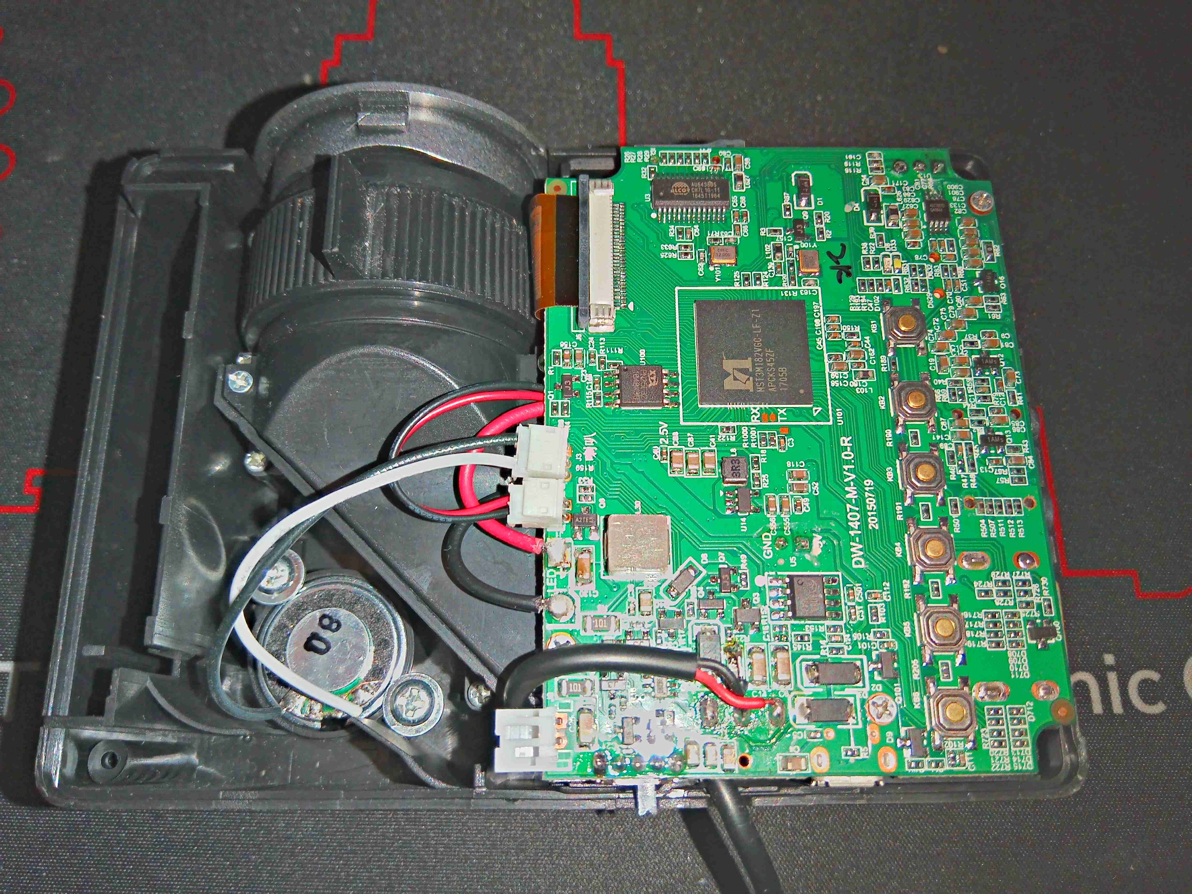
Another Chinese eBay teardown! This is a “720p” LED projector, available from nearly everywhere for very little cash. But they are very little cash for a reason – they’re total shit. The resolution as stated is a blantant lie – the LCD panel used in these is usually around 320×240, nowhere near the 1280×720 as stated. Being small & portable, there’s very little lighting power available, and they barely work to a level watchable without eye strain even in a completely dark room. You literally get what you pay for! Above is the projector with the top removed, showing the main board, which is fairly densely populated.
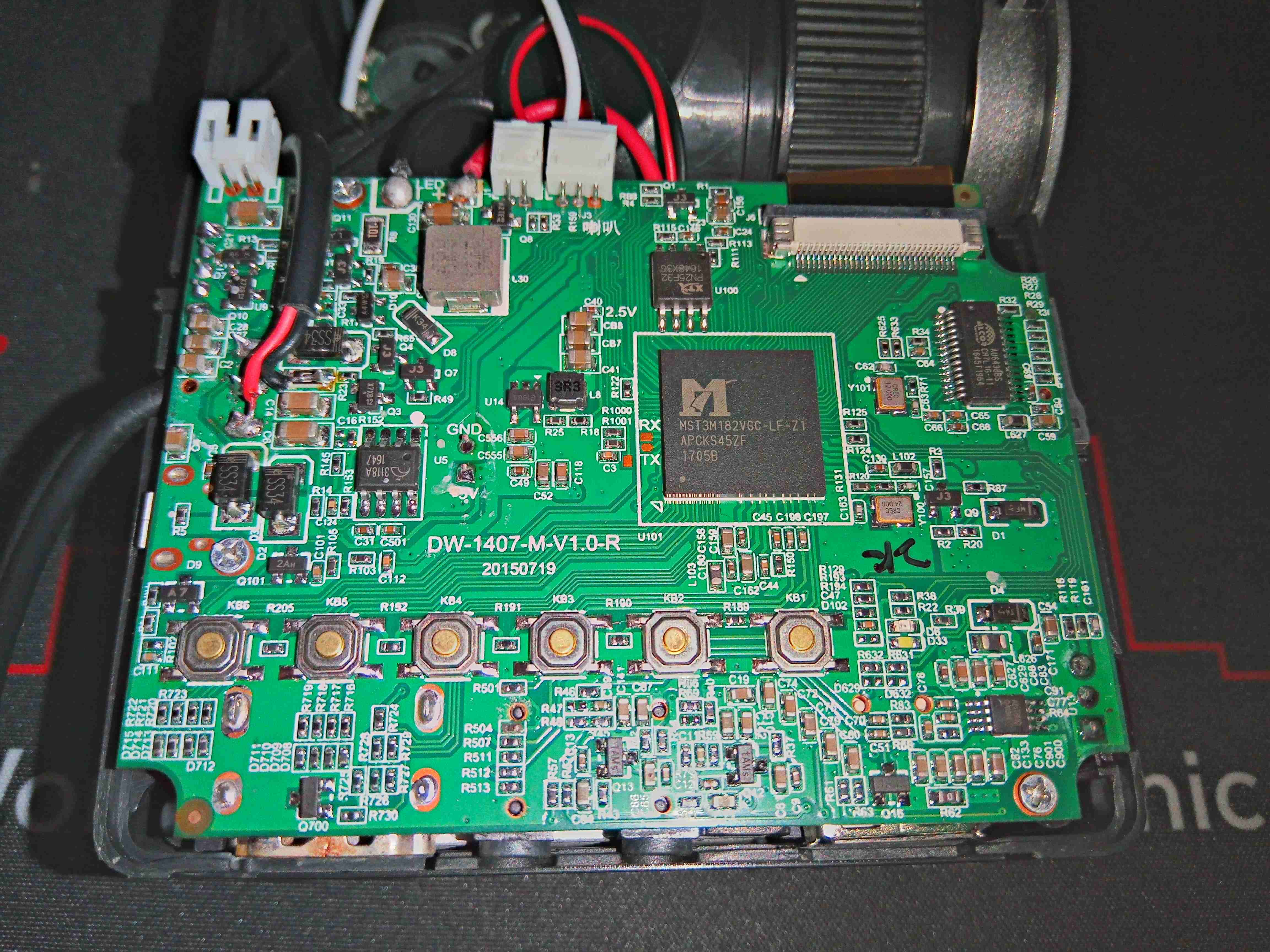
The main processor appears to be an MST3M182VGC-LF-Z1, a SoC designed specifically for LCD TV applications. This runs the internal firmware from a serial flash, a PN25F32 32Mbit (4MB). As this projector has the capability to play files from USB & SD Card, as well as from A/V inputs, there’s an Alcor Micro AU6438BS USB 2.0 Single LUN Flash controller on the right to deal with the MicroSD slot interfacing. The left top corner of the board is completely dedicated to power control, with various switching converters & transistors.
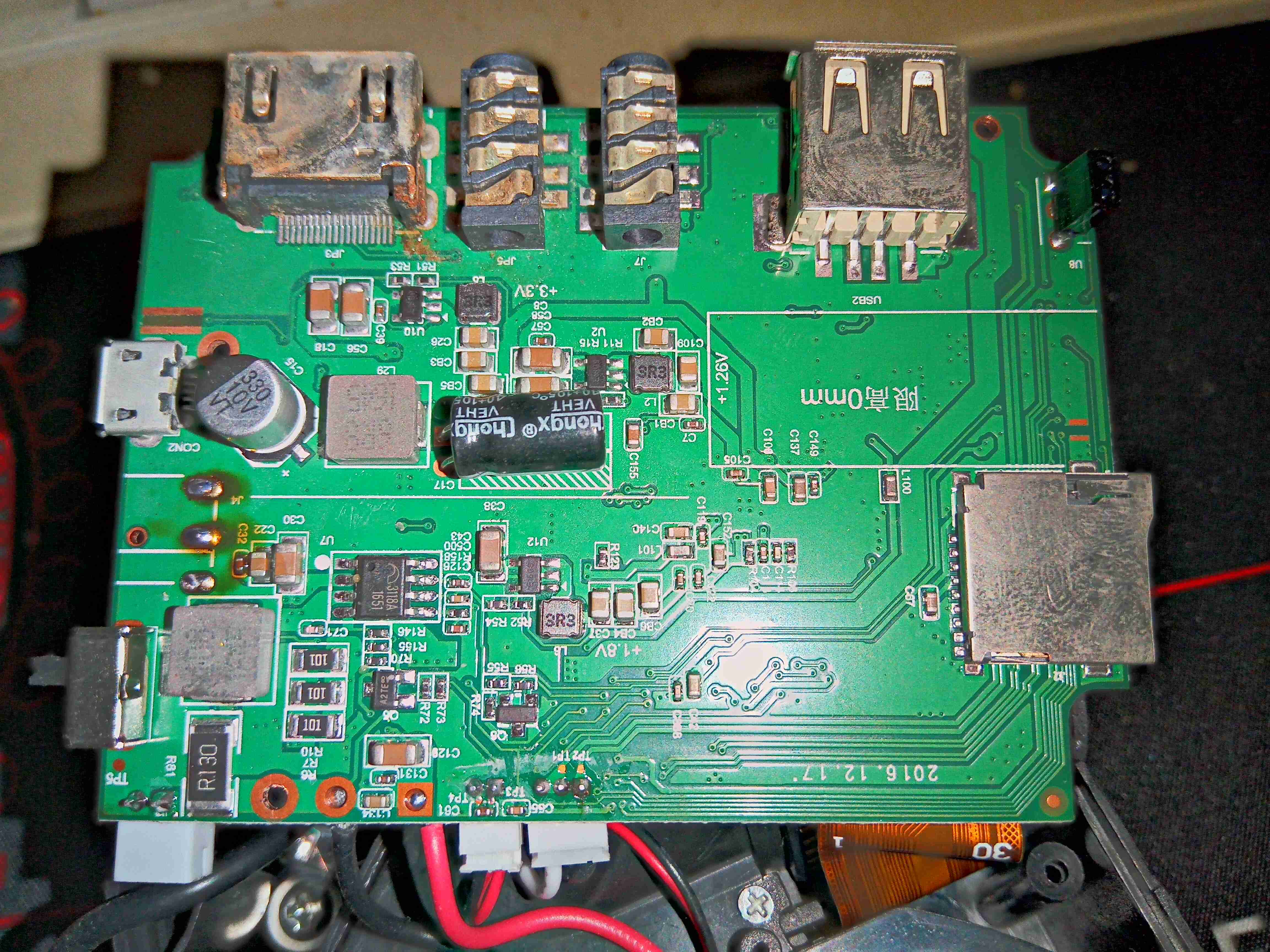
The bottom of the board is also dedicated to the remaining portion of power control – more switching regulators here generate the voltage rails required for the SoC, along with LED drive.
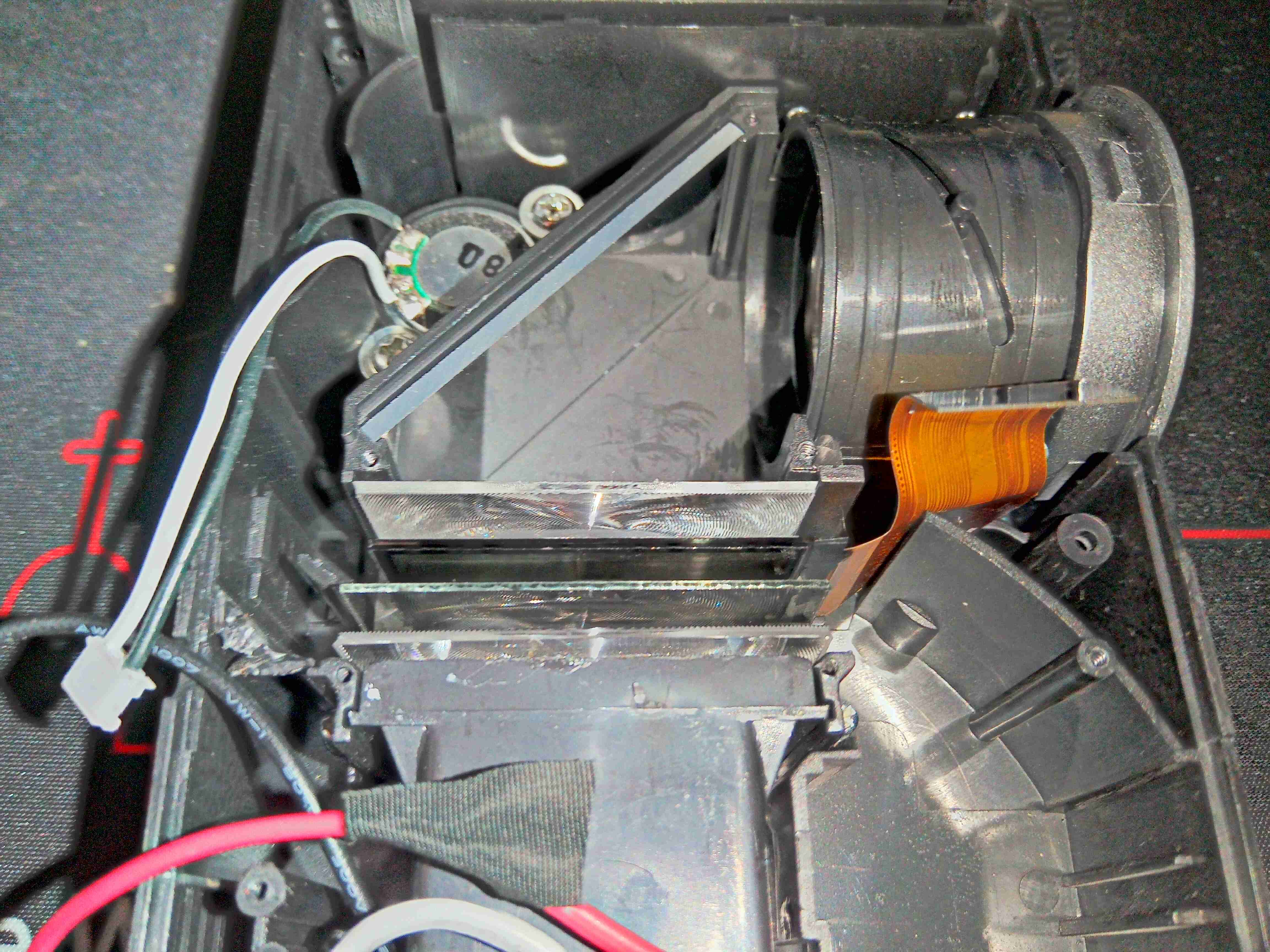
Removing the board allows access to the optical components of the projector.
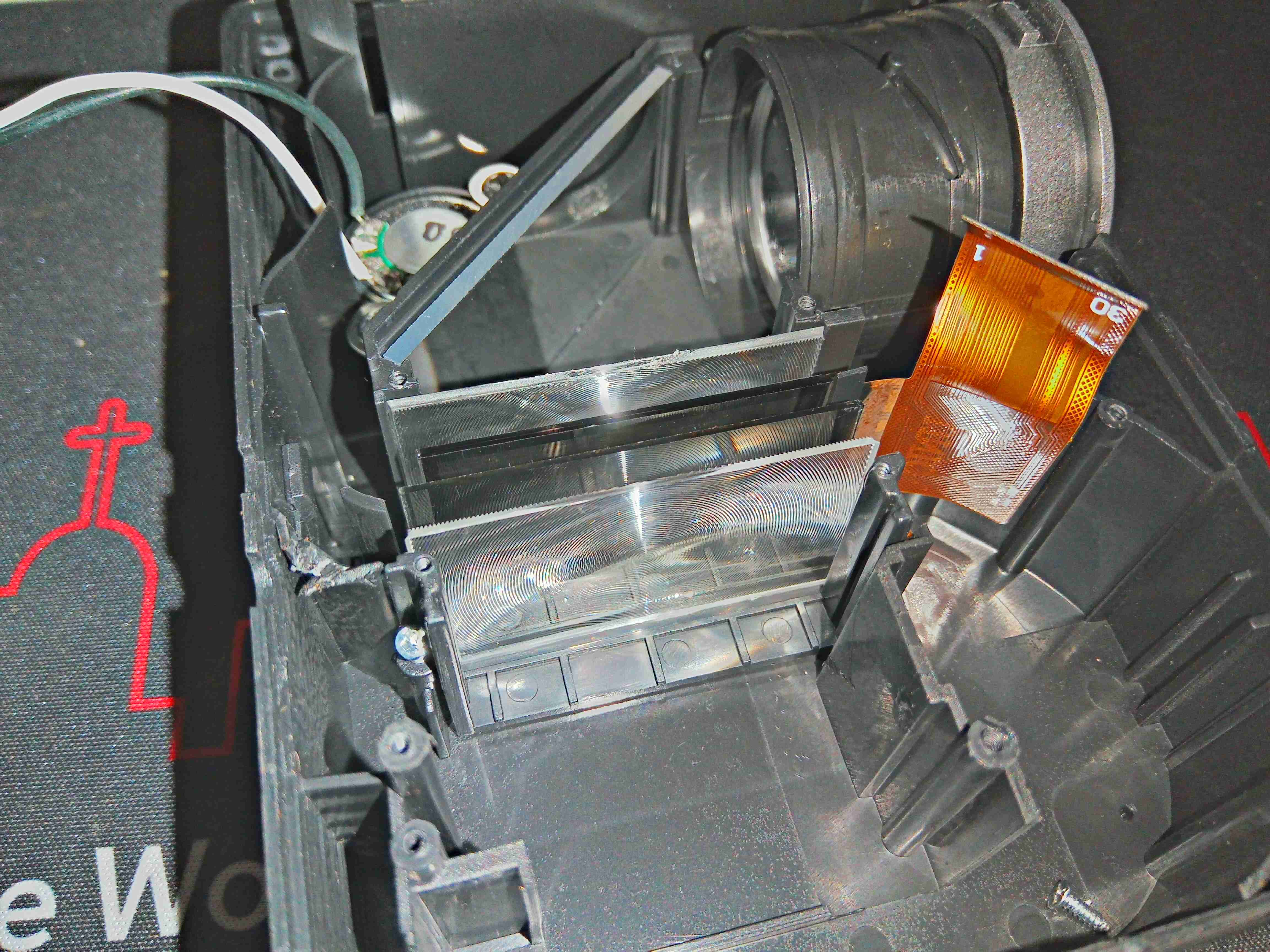
Here the LED module has been removed from the casing, better showing the optical arrangement. There’s a Fresnel lens, then a polariser, the LCD panel itself, another lens, then the final turning mirror to the objective lens.
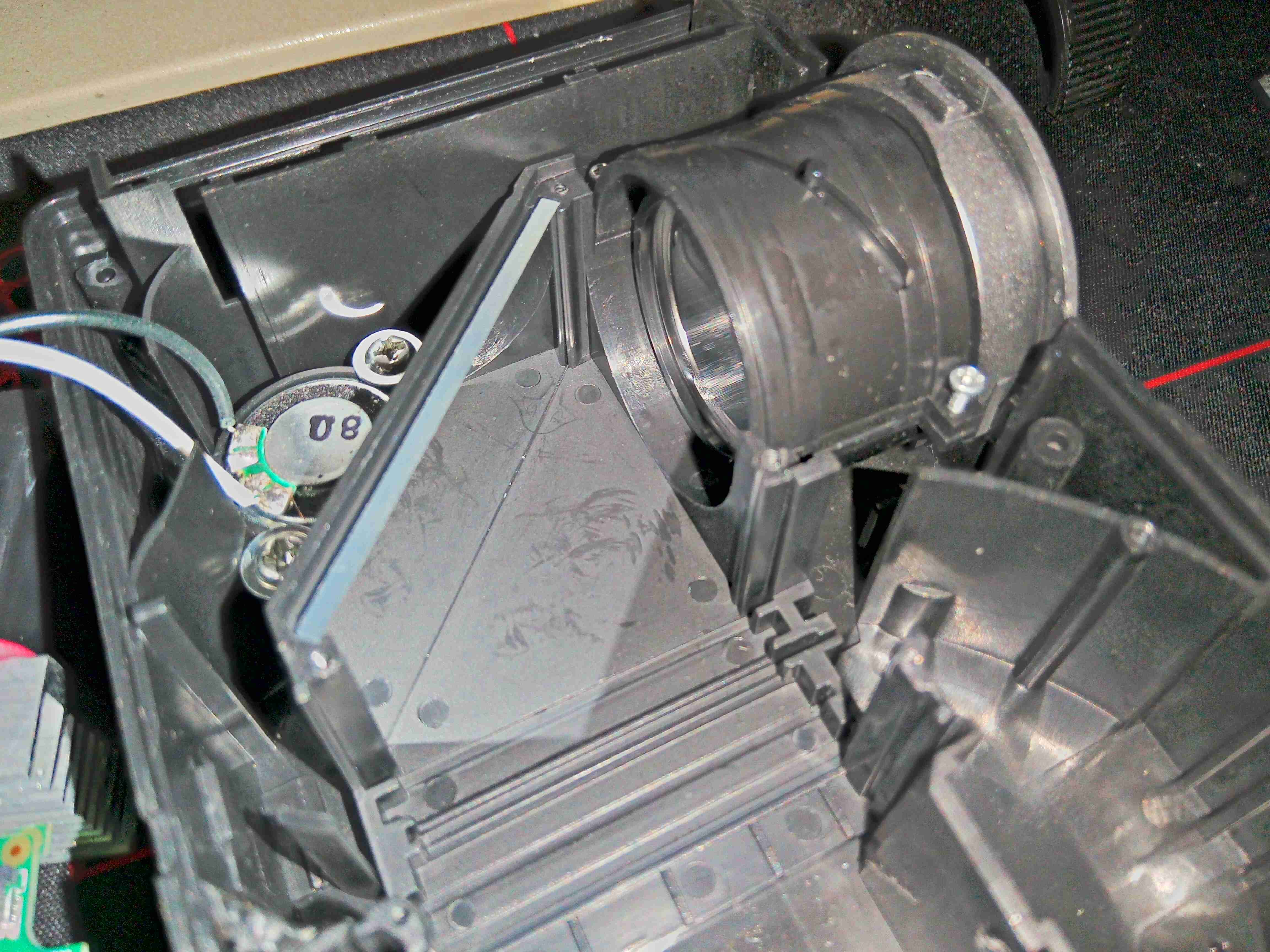
Here the rest of the optical components have been removed, showing the objective with it’s helical focusing track, which moves the lens, and the turning mirror. Behind the mirror is the pitiful speaker.
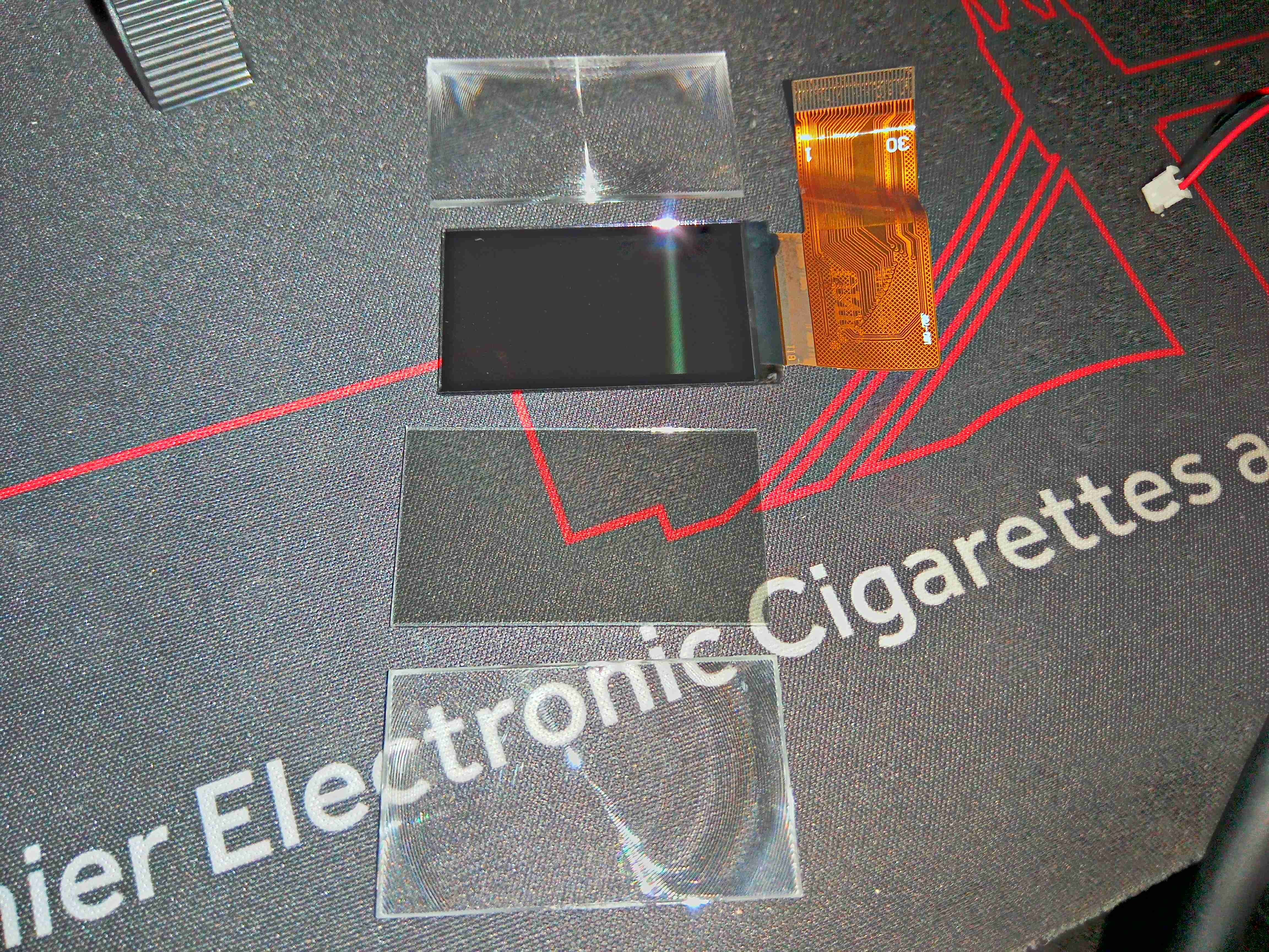
Here the main components are laid out, with lenses either side of the LCD & polariser.
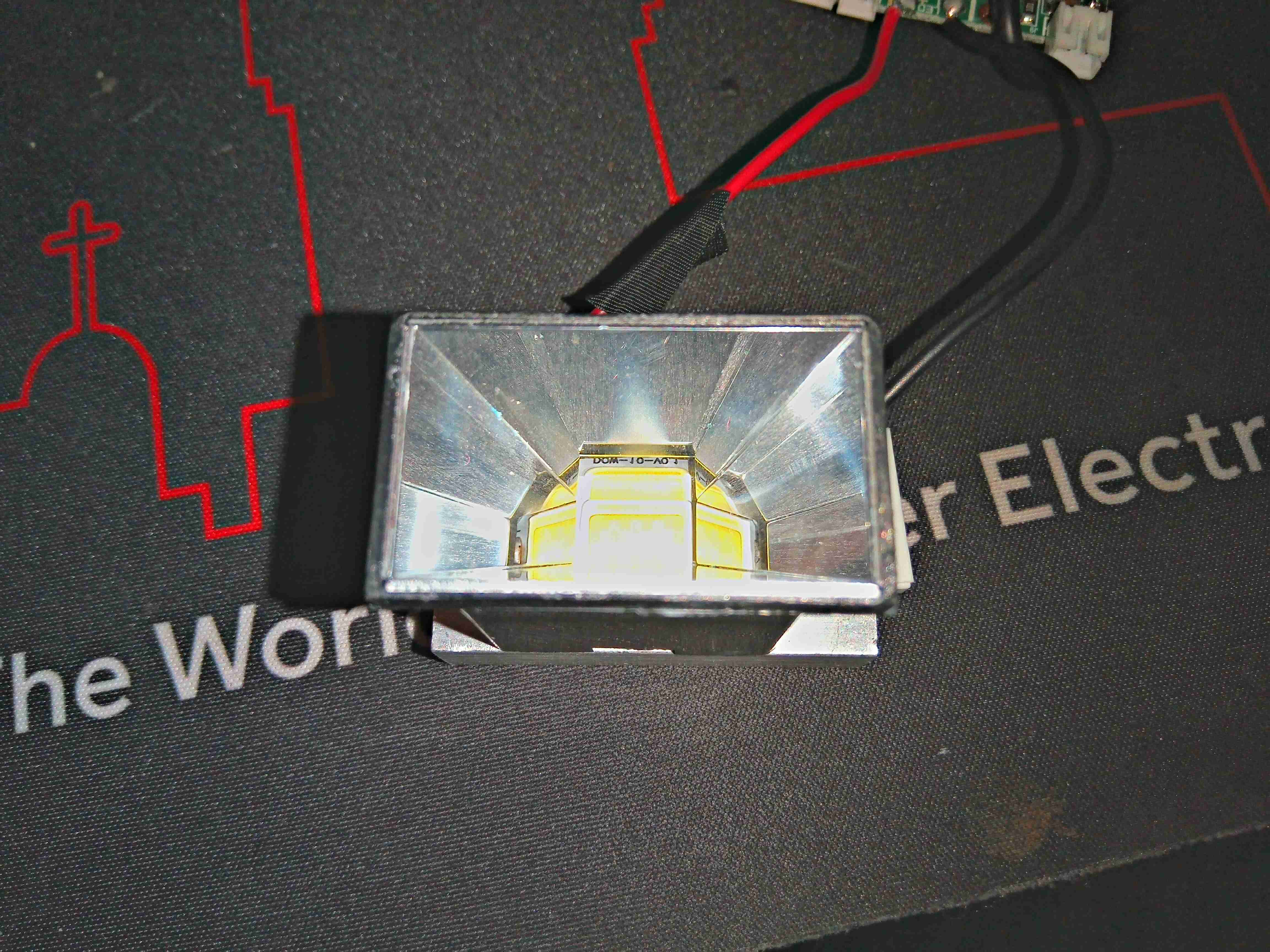
Now onto the light source of the projector – the LED module. This is buried inside the module with a conical reflector, and a small heatsink on the back.
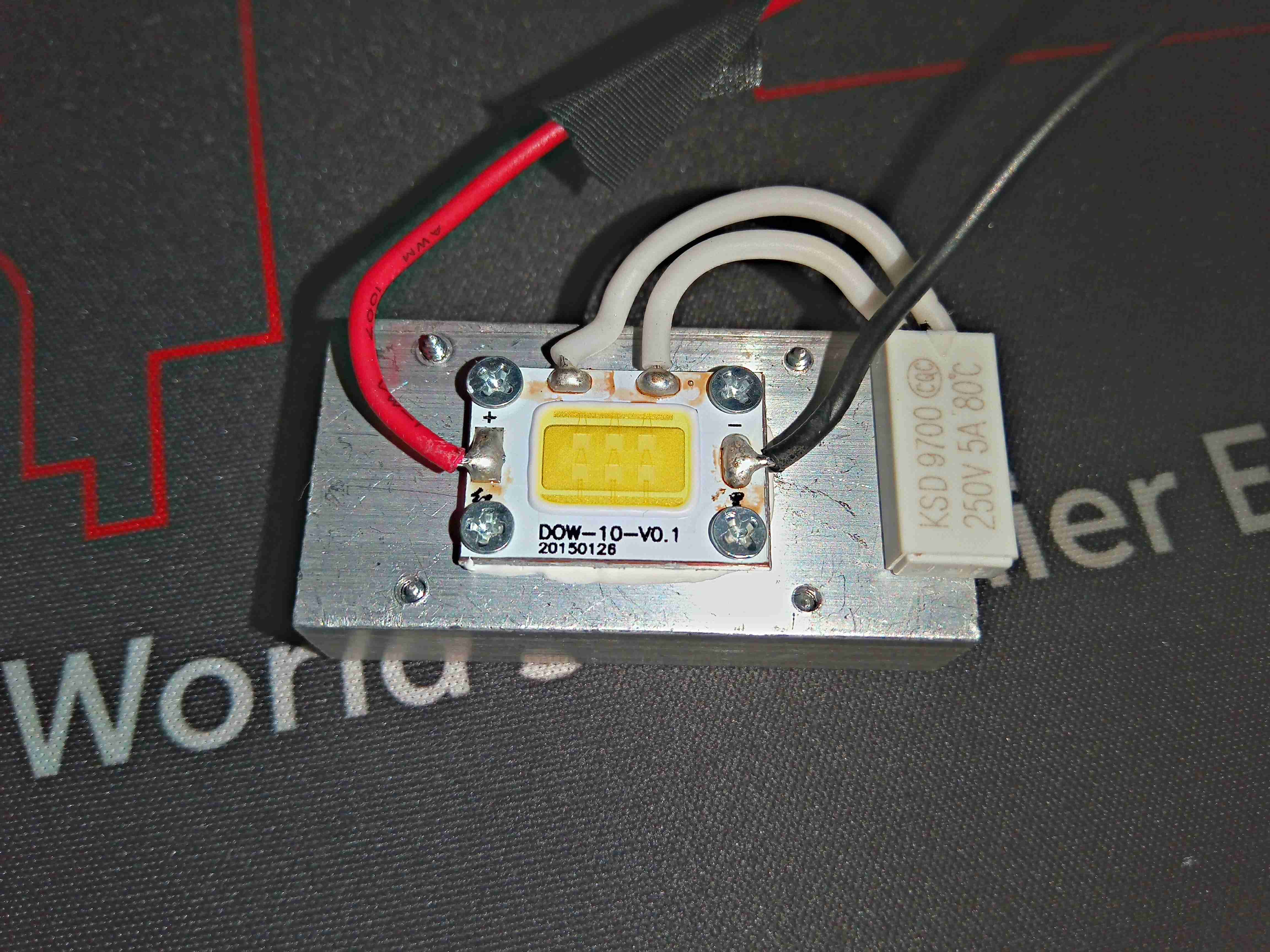
Removing the reflector shows the LED itself, with a thermal fuse in series for protection. The LED is screwed to the aluminium heatsink for cooling – my guess is this is roughly a 6W LED, with 3 series pairs of dies in parallel.
