Posted on Leave a comment

Contec ECG80A Electrocardiograph Teardown

Contec ECG80A
Contec ECG80A

I figured it was about time I added to the medical kit, and since Contec, who makes my SPO² meter seems to have a decent level of manufacturing quality, one of their ECG machines seemed like a good choice. This is the ECG80A handheld Electrocardiograph. This is a single channel, 12 lead unit – meaning it’s a full 12 lead ECG, but it records one lead at a time, in sequence.

Control Buttons
Control Buttons

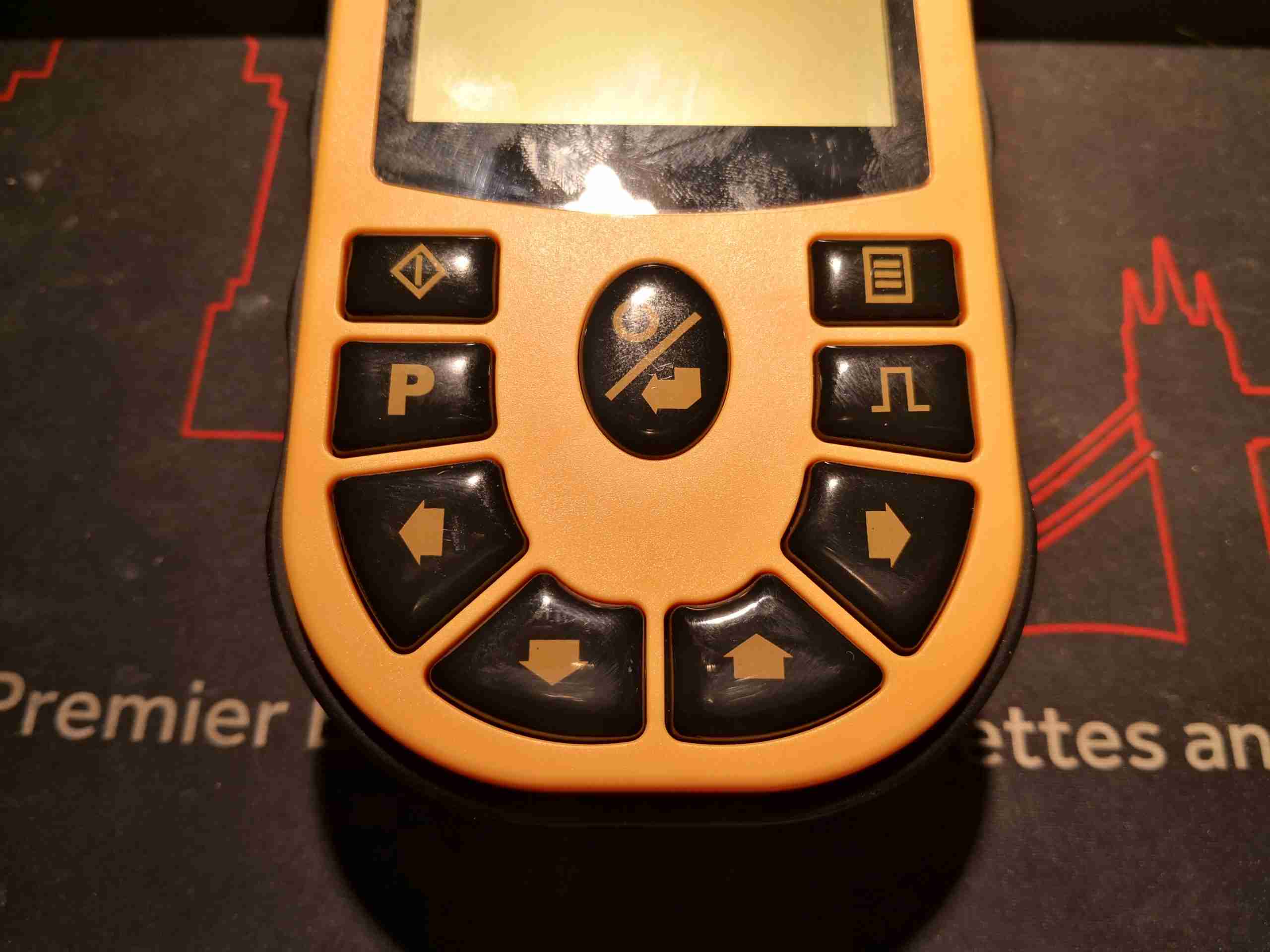
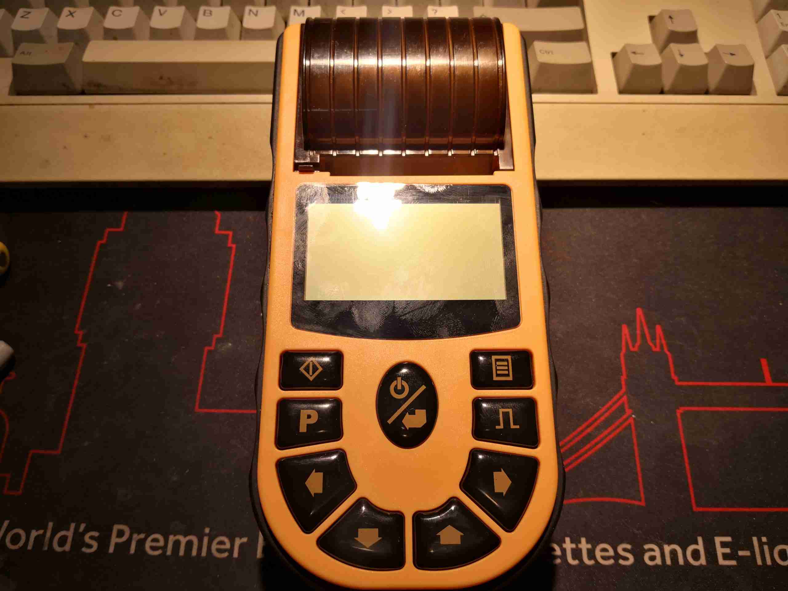
Control is via the front panel, with some large buttons.

LCD Display
LCD Display

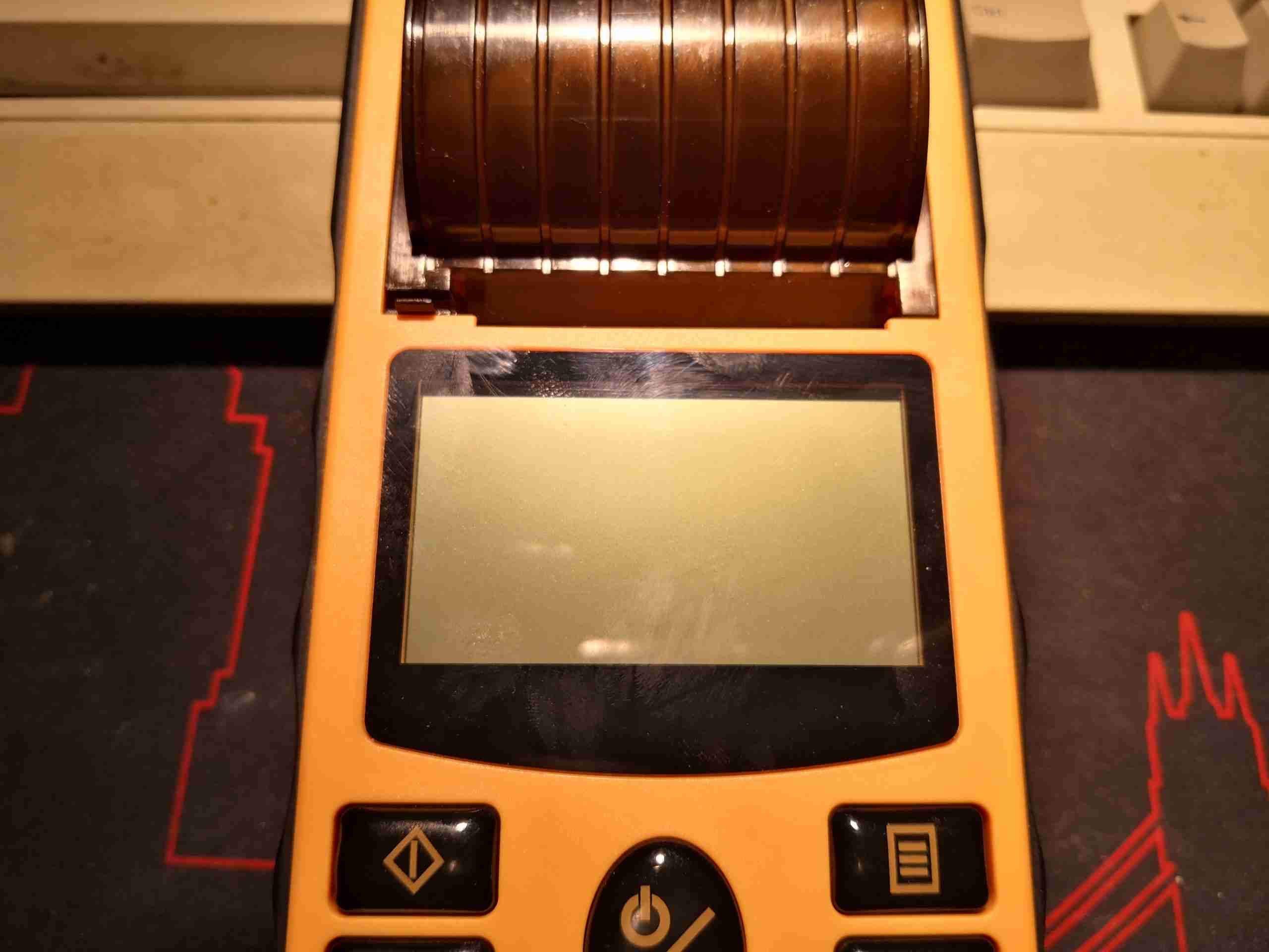
Readout is provided on a dot-matrix LCD, which is brightly backlit. There’s a thermal printer for rhythm strips, printing onto 50mm wide paper rolls.

Labelling
Labelling

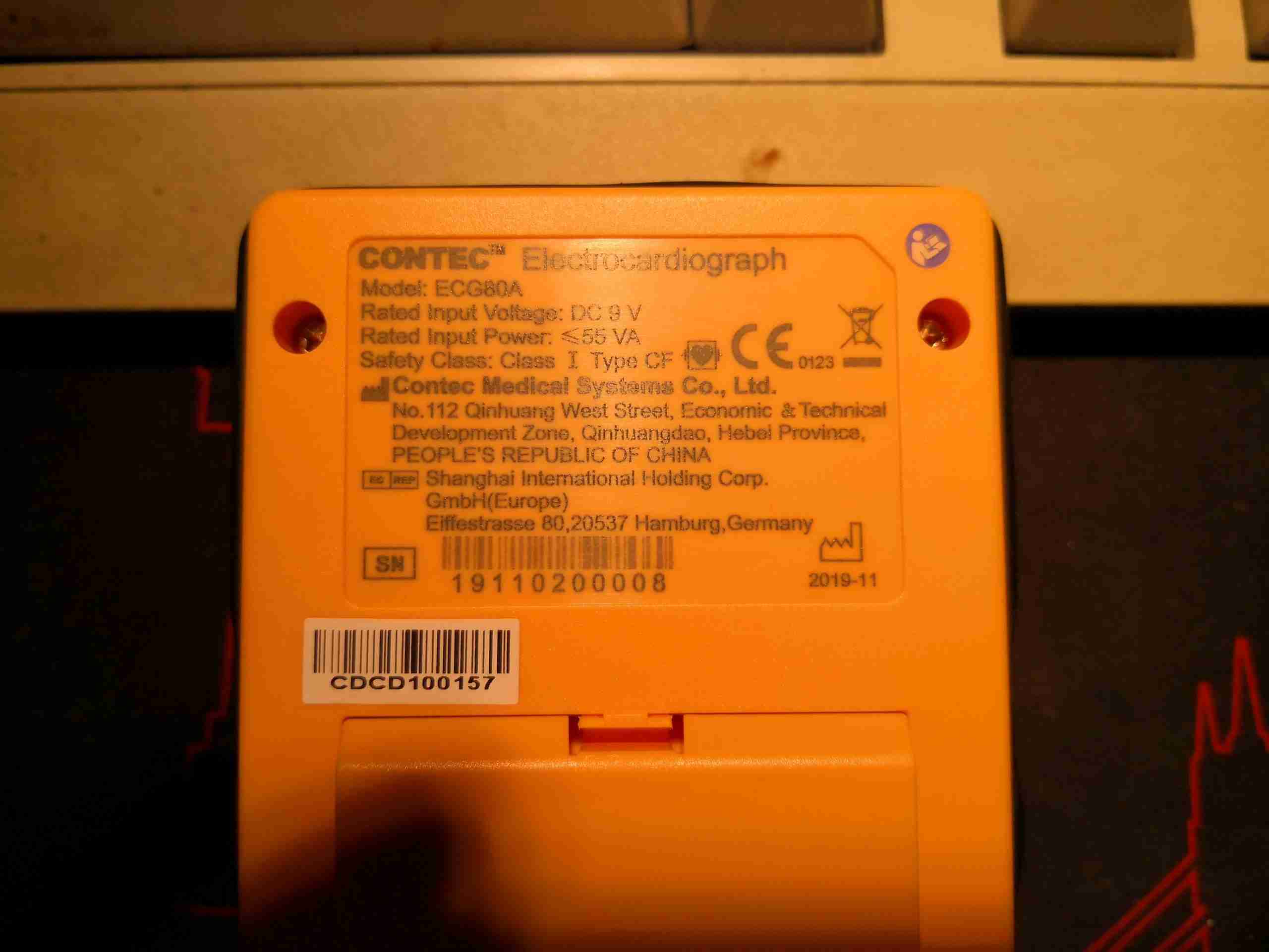
The rear has the laser-marked rating plate, with all the specifications & regulatory markings. From the serial numbering, it looks like my unit was manufactured on 3/11/19, and was the 8th unit off the production line. Underneath can be seen the top of the battery pack, which just clips into place. There aren’t any markings on this at all, but I do know from the manual it’s a 7.4v 2S Li-Ion pack, energy capacity is another unknown, but there is very little weight to the battery, so it can’t be that large.

Internals
Internals

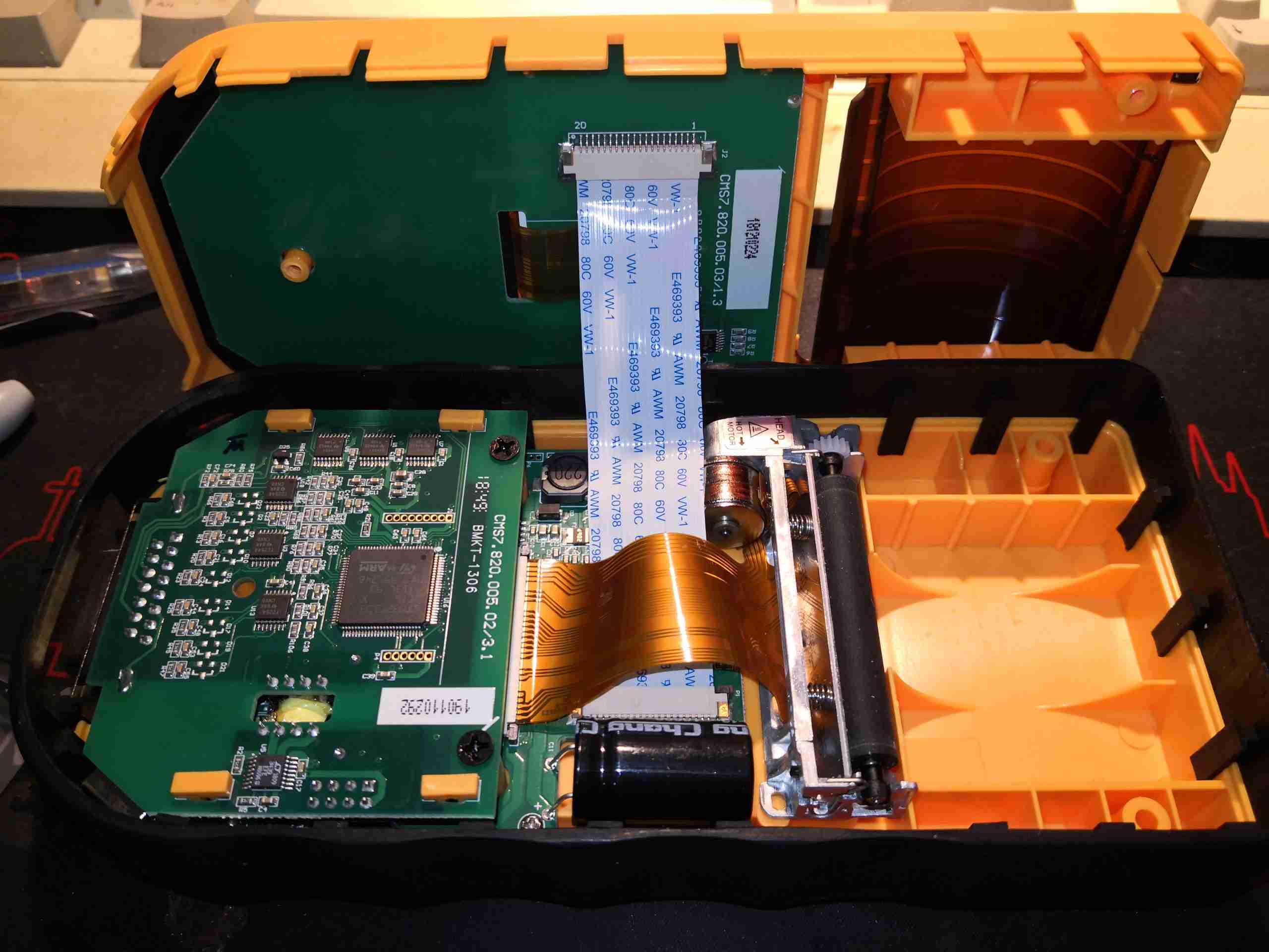
3 Philips screws hold the unit together, and once those are removed, the shell halves separate. The FFC to the LCD & button pad is currently keeping things connected together.

Acquisition PCB
Acquisition PCB

The first of 3 PCBs inside the shell is the acquisition PCB, with all the patient-connected circuitry. The DB-15 connector is on the right hand side, where the ECG leadset connects.

Signal Switching
Signal Switching

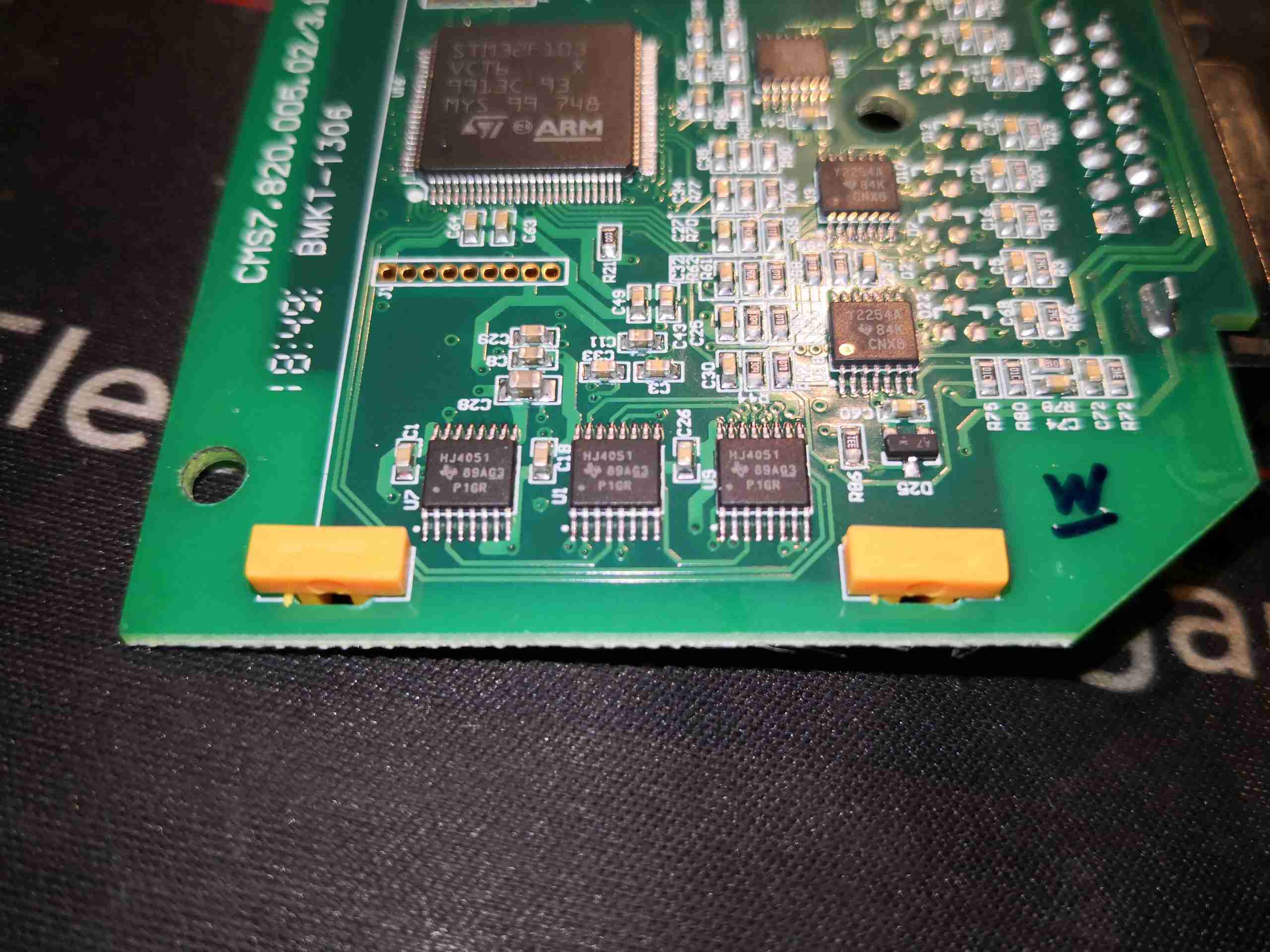
The bottom edge of the PCB has a trio of HJ4051 high speed analog multiplexers, which are switching the ECG leads onto the Ultra-Low Power Op-Amps on the right, a trio of TCL2254A devices from Texas Instruments, before being sent on to the ADC.

Acquisition PCB Bottom

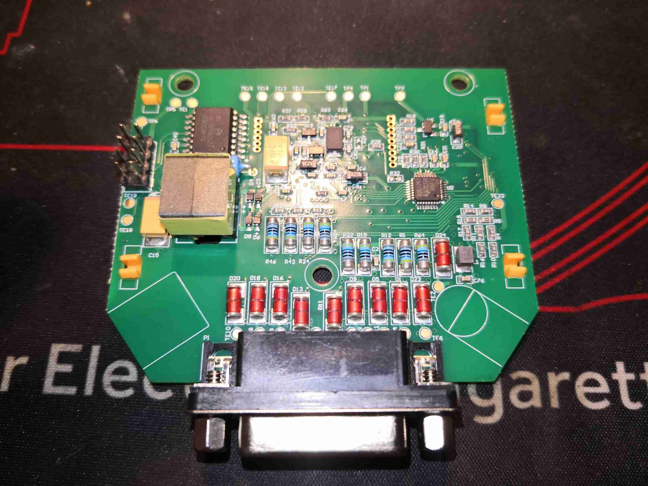
The bottom of the PCB has the DB-25 connector, along with the input protection diodes & resistors. This array of protection components serves two purposes – protection of the instrument against defibrillator voltages & protection of the patient from electrical shock by the instrument.

Signal Isolation
Signal Isolation

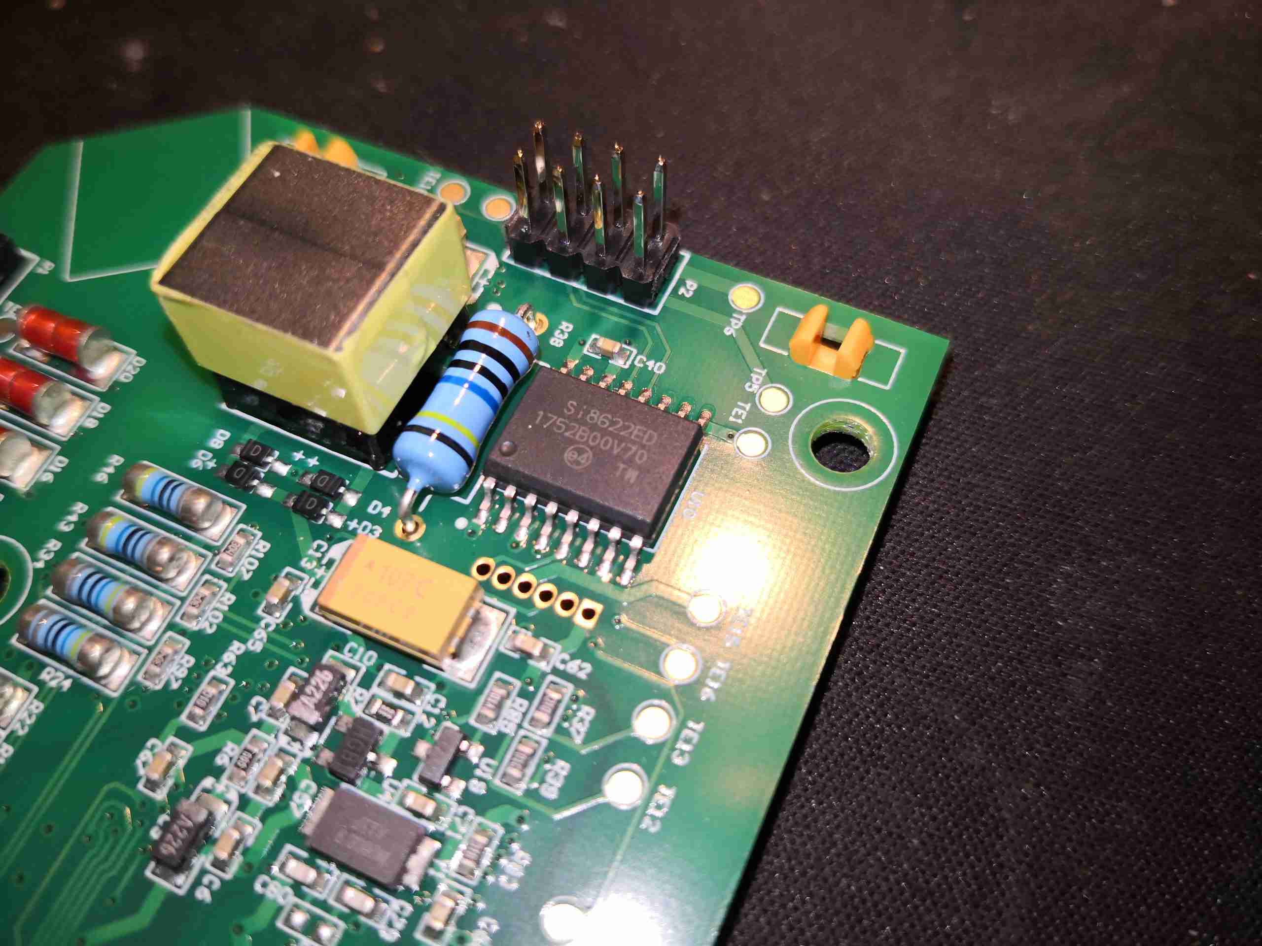
A 5kV isolation barrier is provided between the rest of the unit & the acquisition board, both for the data path & power path. The isolation transformer is visible on the left here, next to the 8-pin header that connects to the main PCB. There’s a 100MΩ resistor across the isolation barrier, probably for ESD bonding. To the right of that is a SiLabs Si8622ED single channel digital isolator IC.

ADC
ADC

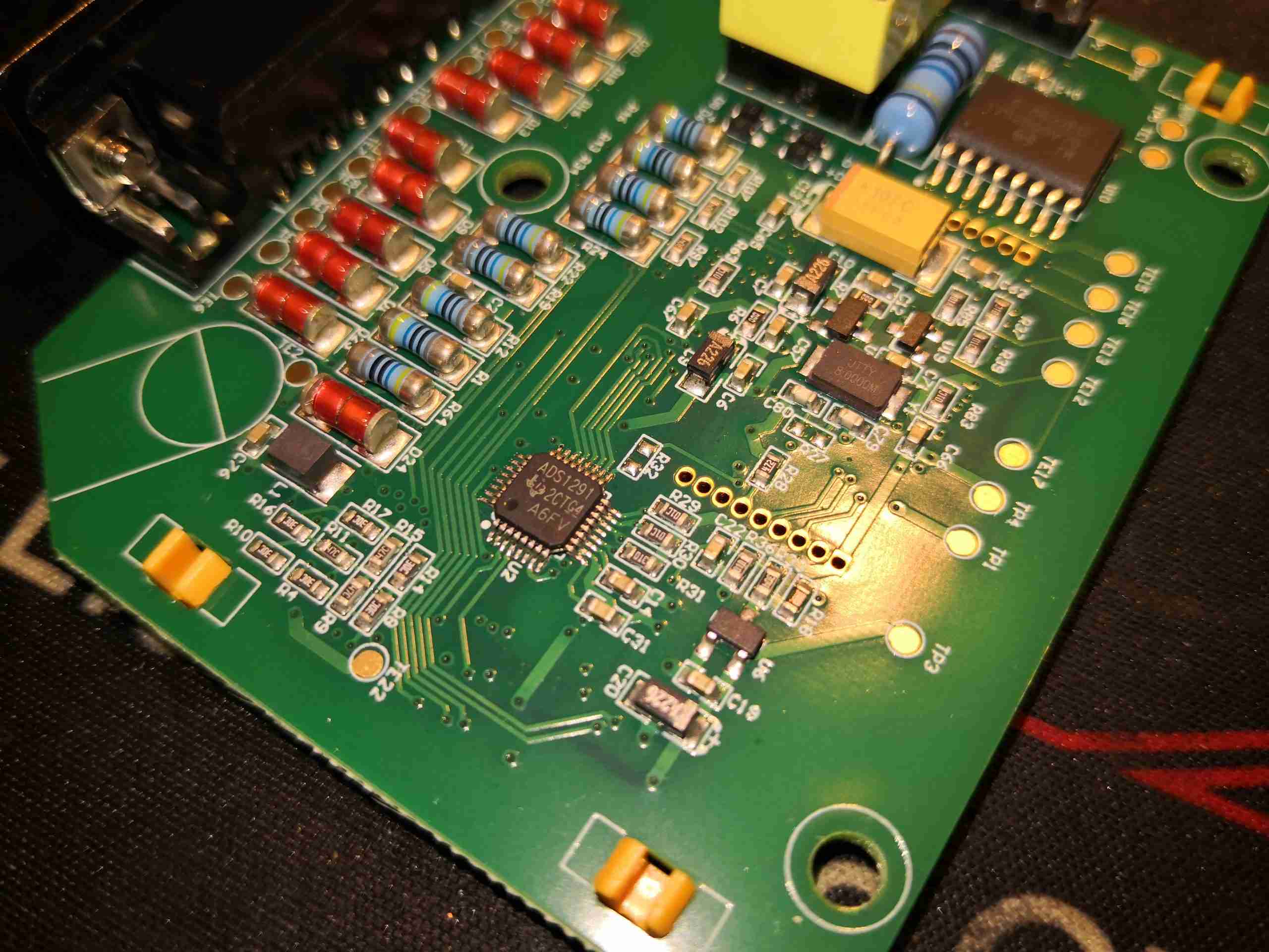
The final bit of conversion of the input waveform is performed by a Texas Instruments ADS1291, a 2-channel 24-bit Analogue front-end specifically designed for Bioelectrical measurement such as ECG. This contains a ΔΣ ADC, and a pair of Programmable Gain Amplifiers on the input, together with some multiplexing. This communicates via SPI to the host microcontroller.

Isolated Power Supply

Power is transferred across the isolation gap through the transformer, driven by a Linear Tech LT3439 slew-rate controlled ultra low noise isolated switching supply driver.

Mainboard
Mainboard

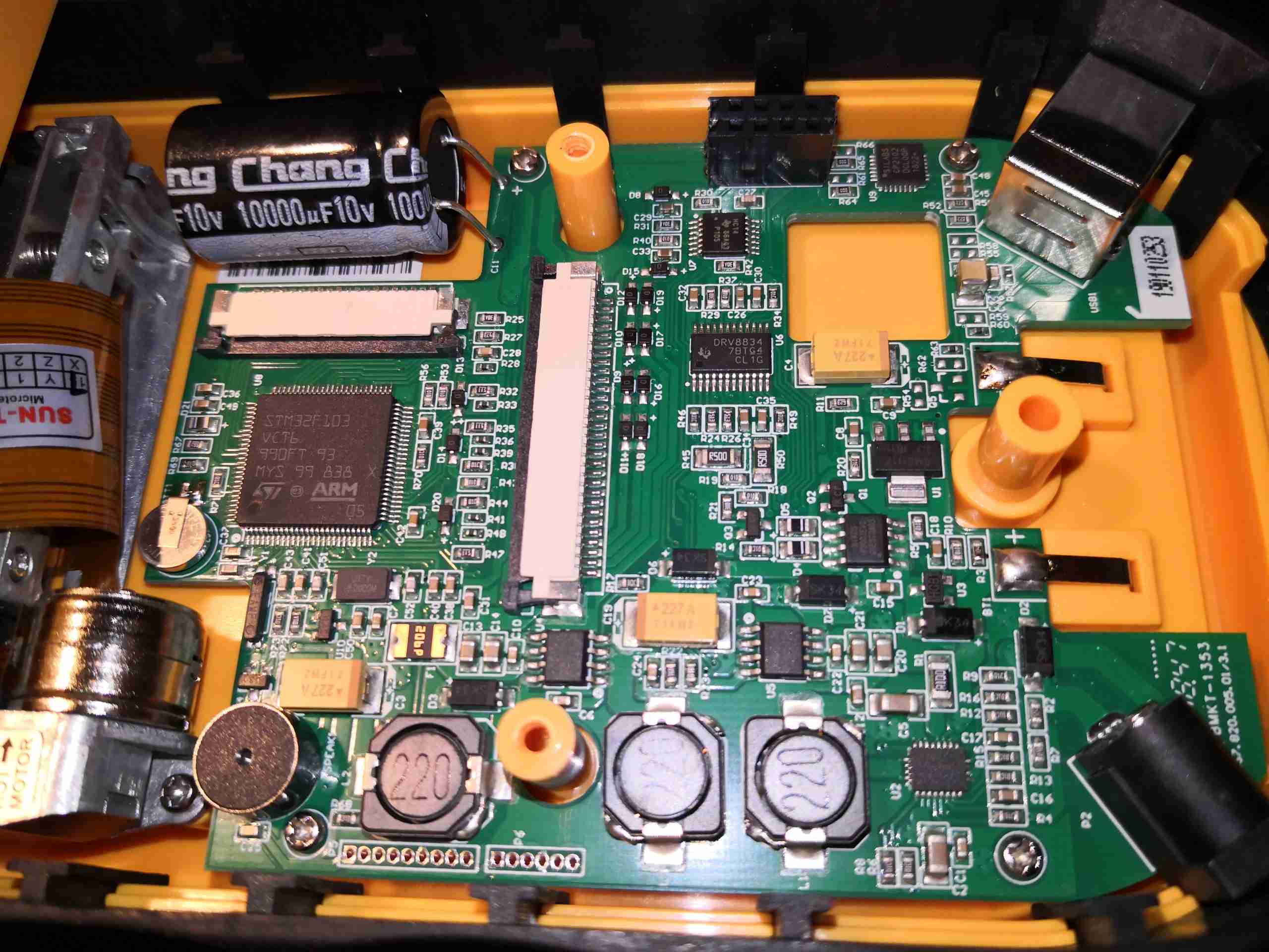
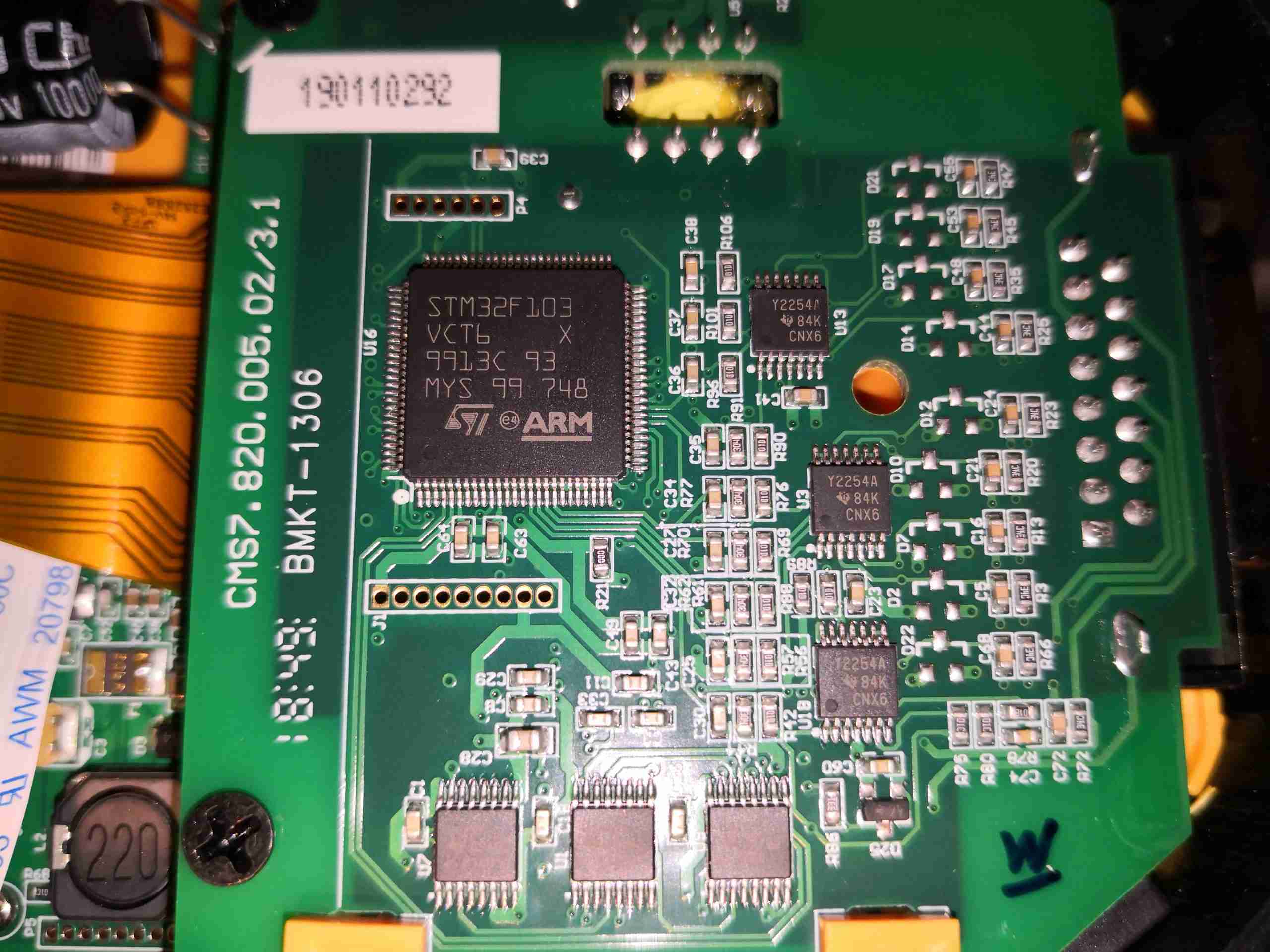
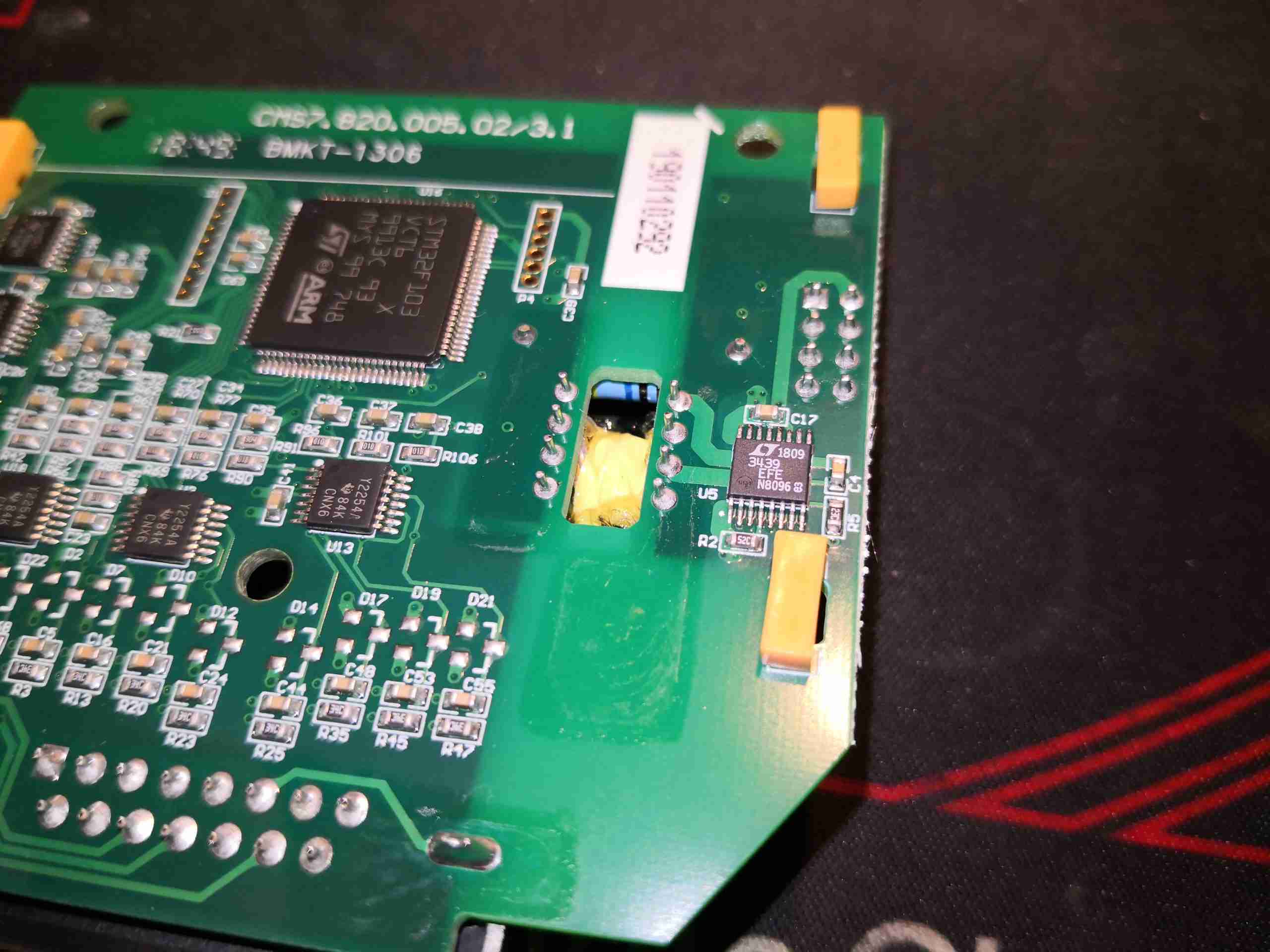
Underneath the acquisition board is the main PCB itself, with the rest of the support electronics. On the lower edge of the board are the power supplies, the main microcontroller on the left, another STM32F103, USB Serial communications top right, and DC input bottom right.

Main CPU
Main CPU

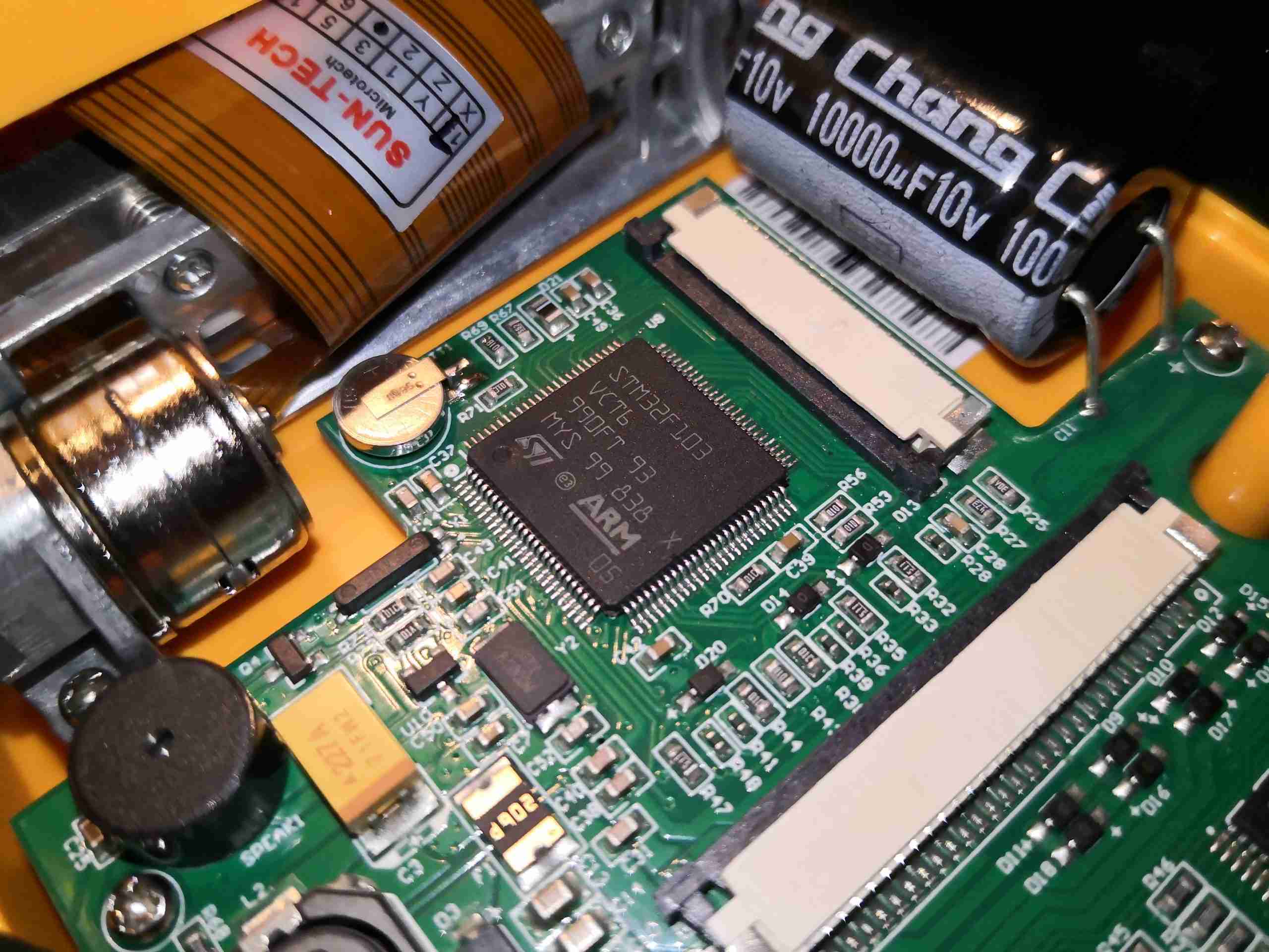
Here’s the main microcontroller with it’s support components. This will be receiving a datastream from the acquisition microcontroller, probably I²C considering the single-channel digital isolation, and further decoding this for either display on the LCD, printing on the thermal paper or sending as a datastream over USB Serial to a PC.

Power Supplies
Power Supplies

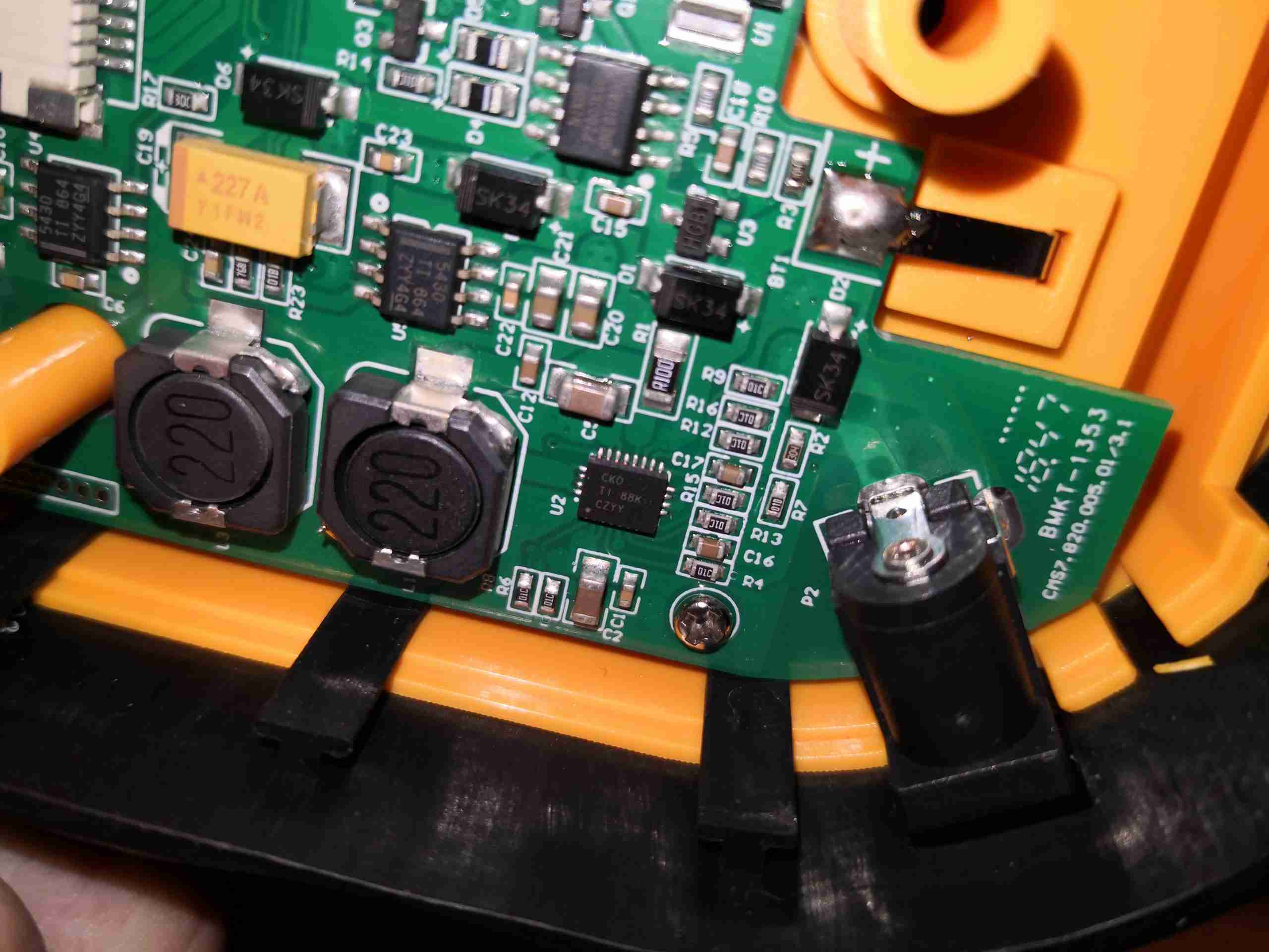
The onboard 2S 7.4v Lithium Ion battery is handled by a Texas Instruments bq24103A Synchronous switched-mode charge management IC here, just to the left of the barrel jack. It’s inductor is just to the left of the IC. This is a fairly nice chip, with support for up to 3 series cells with full auto sensing.

DC-DC Converters
DC-DC Converters

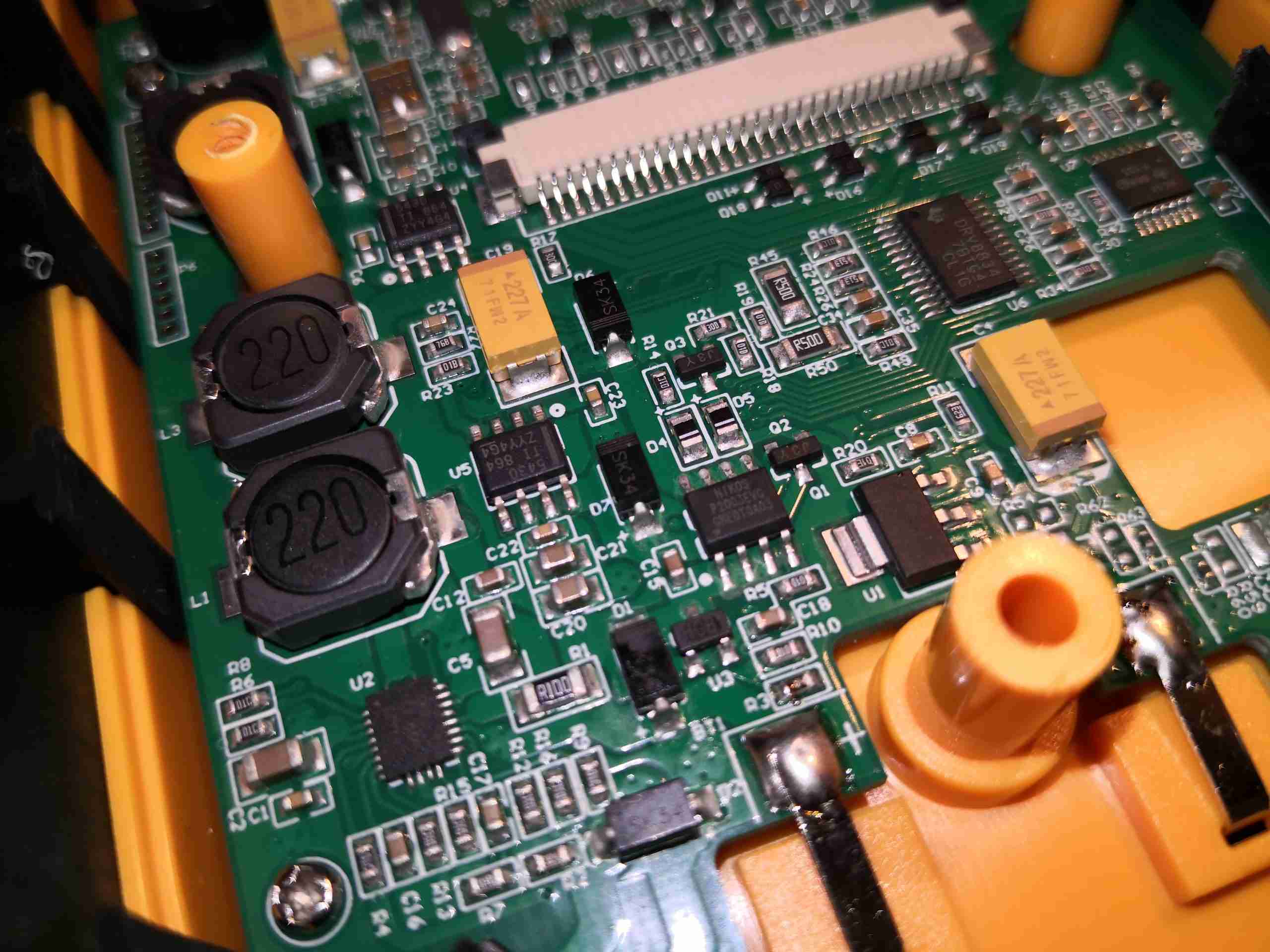
Other power supply rails are dealt with via a pair of TPS5430 buck converters, again from TI. Their associated inductors are along the left side of the board. There’s also an LM1117-3.3 linear regulator for a low-noise supply, possibly for the microcontroller power rail. There’s also a few discrete switching components, and a DRV8834 bipolar stepper driver for the printer.

USB Interface
USB Interface

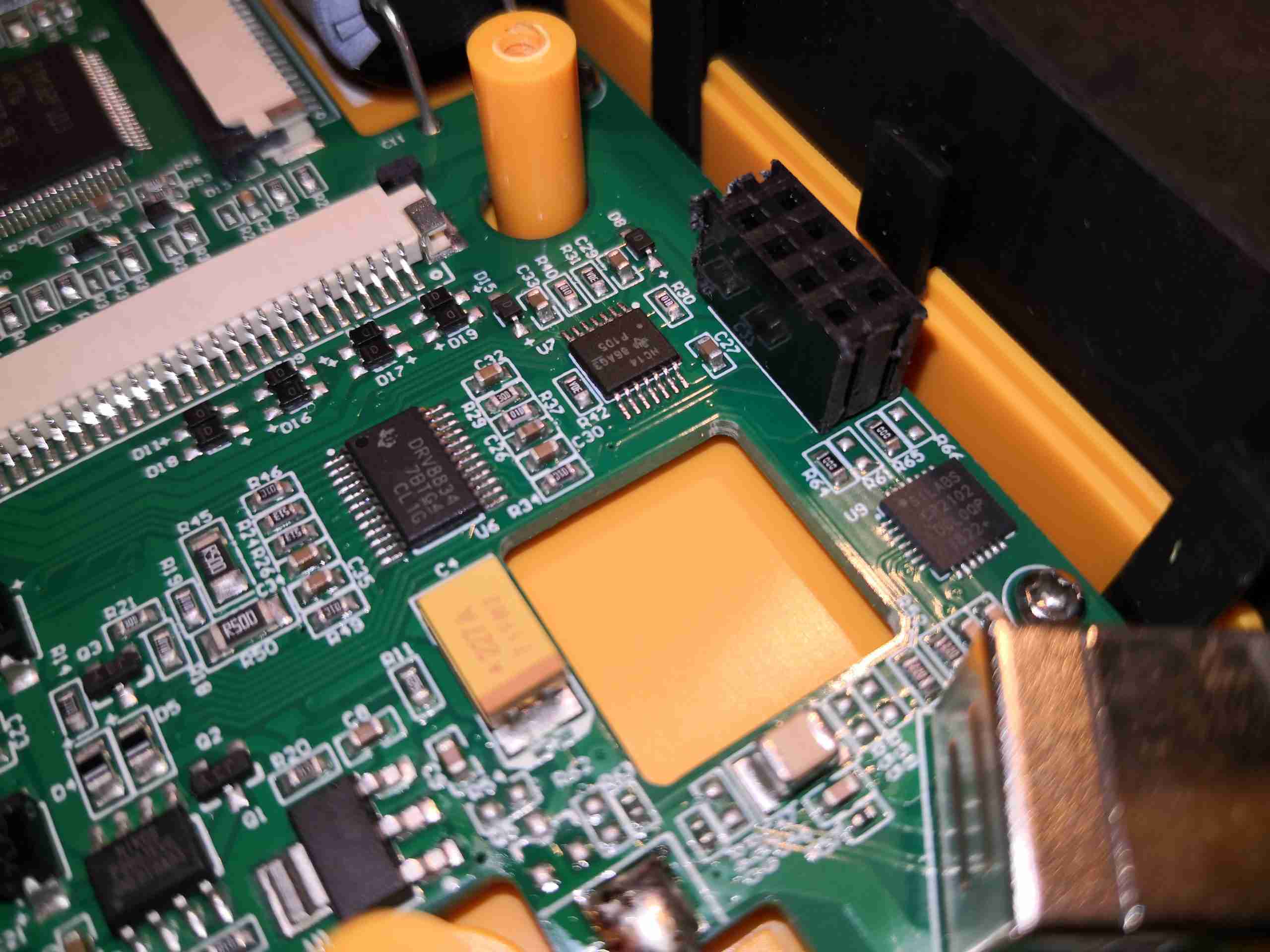
Finally, in the corner of the board is the USB connector, with a SiLabs CP2102 USB UART IC. This interface is used with the optional PC Software. The routed hole in the PCB is clearancing for the isolation transformer of the acquisition board.

Printer Module
Printer Module

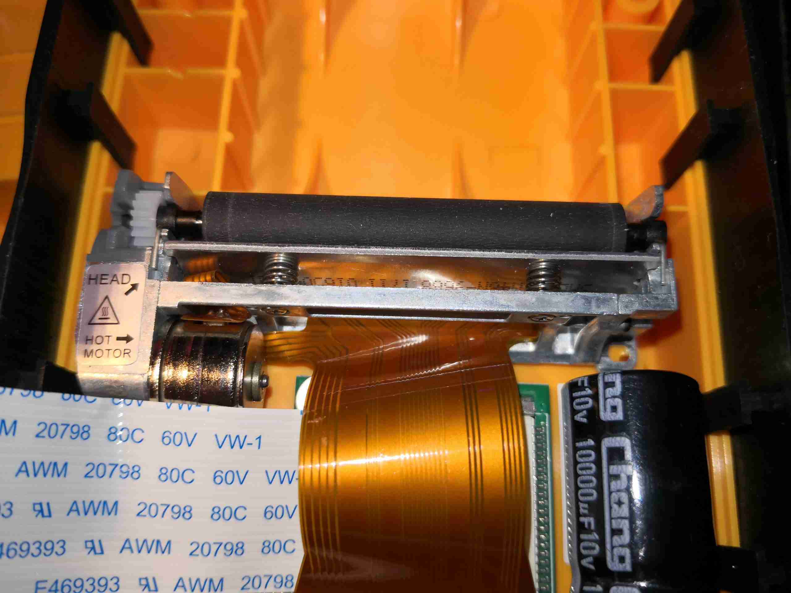
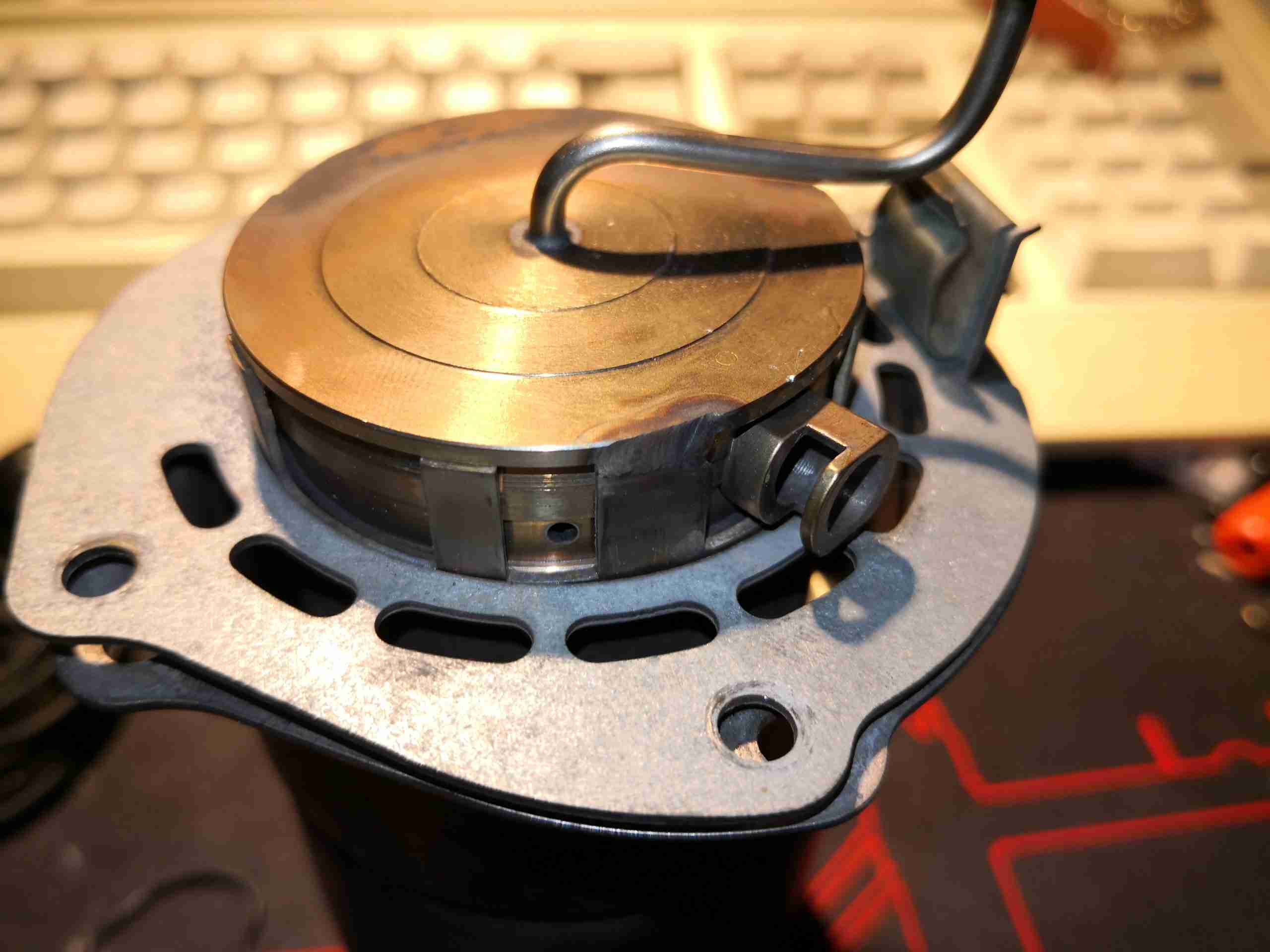
Here’s the printer module, at the top of the shell. There’s a tiny stepper motor on the lower left that moves the paper past the print head, which is the bar mounted on springs across the centre. The odd thing with this is to load the paper, the black rubber pinch roller has to be completely removed from the printer, the paper placed across the print head, and the roller clipped back into place – instead of the roller being mounted on the front cover like on most thermal printers.

Printer Label
Printer Label

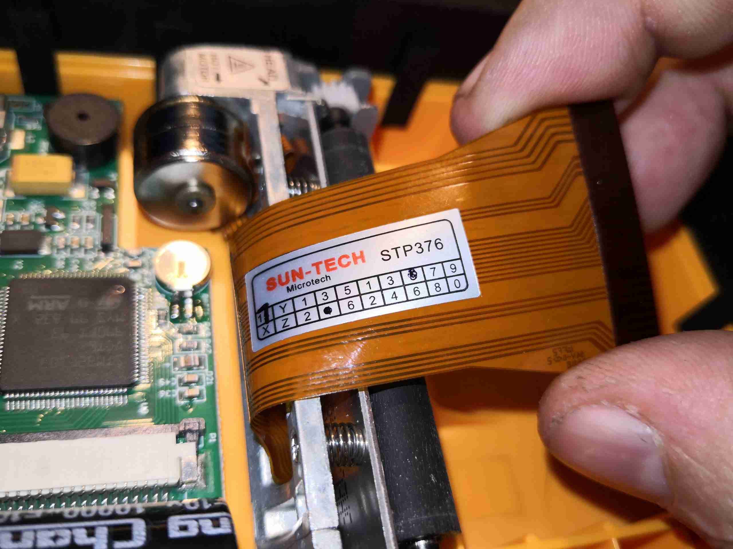
The printer module is manufactured by Sun-Tech, the STP376. I’ve not managed to find any information on this at all, either the manufacturer, or the part number. I did find a SunTech, in the medical sector, but their logo is very different from the labelling here.

Lead II Example Printout

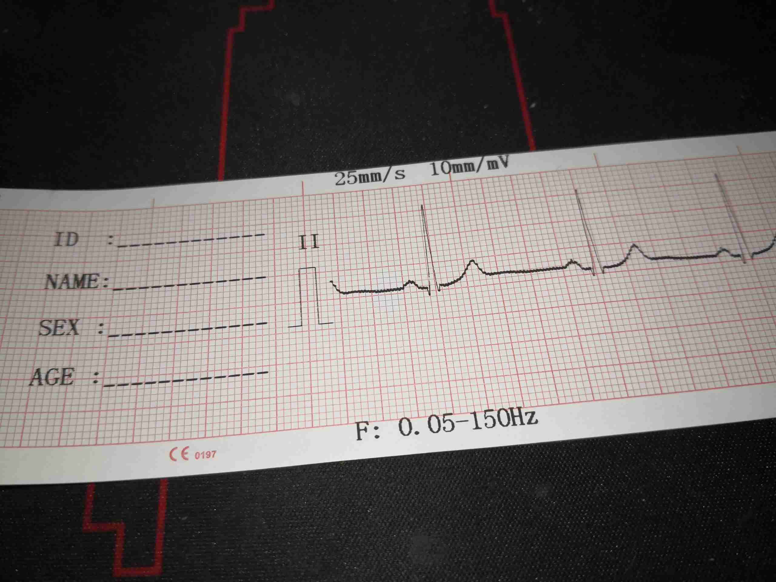
Here’s an example of the print quality of the unit, which just so happens to be lead II taken from me! It’s pretty good overall, with nice clear printing. There is a little interference on the trace that can be seen, but that’s not the ECG’s fault – this trace was obtained in a relatively EMC-noisy environment. The unit first prints a section for patient details, then the lead ident & 1mV calibration mark, then the actual trace. Machine settings are printed in the top & bottom margins, showing the print speed, sensitivity setting, and any applied frequency settings. There is a little bit of interference on the  A full 12-lead printout is roughly 3 seconds per lead in sequence, and takes up about 1.2m of paper at standard 25mm/s speed setting.

Posted on 17 Comments

Webasto Thermo Top C Burner Mesh Replacement

It recently became rather obvious there was something amiss with the water heater on board nb Tanya Louise – lots of smoke from the exhaust, failed starts, and finally a total refusal to start altogether.

Combustion Chamber
Combustion Chamber

On disassembly, it was clear the burner was the issue – above. The mesh at the back where the fuel inlet enters the burner is completely knackered. The burner in these heaters, like the Eberspachers, is evaporative. Diesel fuel is led into a high-surface area mesh tube, or pad in this case, where it is vaporized to be burned with air from the combustion blower. Initially, this heat is provided by the glow plug, but after the unit has fired, the heat of combustion keeps the process going.

Burner Deposits 1
Burner Deposits 1

As can be seen at left, there’s quite the build-up of solid carbon around the burner, blocking most of the mesh & the air mixing holes in the tube. This was also after I’d removed most of the fouling!

Burner Deposits 2
Burner Deposits 2


More deposits are seen on the other side, along with some of the air mixing holes.


Inlet Plate
Inlet Plate

Now, the problem is that these burner units are not meant to be refurbished. These units are considered by the manufacturer to be disposable, and are welded together as a result. There’s another issue – I don’t believe that a component costing around £295 in a service kit as DISPOSABLE. There’s nothing wrong with the structure of the burner at all – it’s Stainless Steel, and is in good shape with no heat damage. The only fault is with the mesh being burned out from long use. Luckily, replacement burner meshes are available on eBay from Chinese suppliers, so on with the repair!
One of the welds that needs to be removed can be seen here next to the glow plug well, and there are 3 spots around the rim that are welded in this way. Delicate use of a grinding wheel on the welds allows this to be removed intact.

Burner Tube
Burner Tube

Once the welds have been ground off, the fuel inlet plate with the mesh can be pulled from the back of the burner. It’s a good idea to add some registration marks to both pieces before they’re separated, so they can be put back together in the same orientation – required for both the glow plug wiring, and the fuel inlet tube to line up with the hole in the heater housing. The ring of slots visible around the edge of the tube are the combustion air inlets, and the air is directed through a ring of holes in the combustion chamber, quite similar to a turbine engine combustor.

Old Burner Mesh
Old Burner Mesh

Now I’ve got the back of the burner removed, the clogging is much easier to see. The mesh itself has clearly been subject to very high heat, and is partially burned away, along with most of the surface being clogged up with coal from incomplete combustion. It’s difficult to see here, but the mesh pad is held in place with a large circlip around the edge, all will become clear after cleaning. All the hard carbon needs to be scraped out of the cup, clearing the way for the clip to be pried out of it’s groove.

Cleaned Cup
Cleaned Cup

After a lot of scraping with the sharp end of a small screwdriver, the cup has been relieved of enough carbon to be recognisable again! The fuel inlet tube is in the centre of the backplate, with the circlip groove around the edge. Crimp marks are visible on the top edge of the groove – I think Webasto actually crimps the ring in place after fitting, which does make removal a bit more tricky, but I did manage to get it out intact, even if heat has removed most of the heat treat from the steel – making it soft. Be careful here!

New Mesh Fitted
New Mesh Fitted

Fitting the new mesh is pretty simple. These have a sharp pressed side & a convex side, the convex side must face outwards from the cup. The circlip is visible around the edge of the mesh, with the ends next to the glow plug well. Make sure that the clip is equally spaced around the glow plug  to make sure it doesn’t foul the plug when that’s replaced.

Now comes the issue of reattaching the cup to the back of the burner tube. I didn’t want to re-weld, since the assembly is Stainless Steel & I don’t have a TIG setup at present. I do have some stainless wire for the MIG, but this would also leave me with the issue of future disassembly if the mesh needs replacement again. Brazing is also not possible for the same reason – once brazed, it’s a permanent assembly.

Burner Reassembled
Burner Reassembled

Since there are some tabs that were never welded, I decided to drill & tap M2.5 through these & use 304 stainless screws to hold the components together. This should allow removal in the future if required.

Posted on Leave a comment

Fake Nagoya NA-771 Dual Band Antenna

NA-771
NA-771

eBay yet again doesn’t disappoint when it comes to fake kit. Here is a claimed dual-band antenna, a Nagoya NA-771. This is supposed to be good for both 144MHz & 433MHz.

Base Logo
Base Logo

The first clue is in the logo printing on the base, it’s not straight, or even. The base isn’t aligned correctly with the connector either, being glued on at a janky angle.

165MHz
165MHz
433MHz
433MHz

Beyond looks, a network analyser really shows the problems. Here’s a scan from 50MHz to 500MHz. There’s a fairly decent SWR of 2.01:1 at 164MHz (the tuning is still off, it’s supposed to be at 144MHz), but the SWR at 433MHz is 13:1!

544MHz
544MHz
920MHz
920MHz

Extending the range to 1GHz does show another couple of resonant points, at 544MHz (1.99:1) & 920MHz (2.83:1), well outside the band that this antenna is supposed to work to.