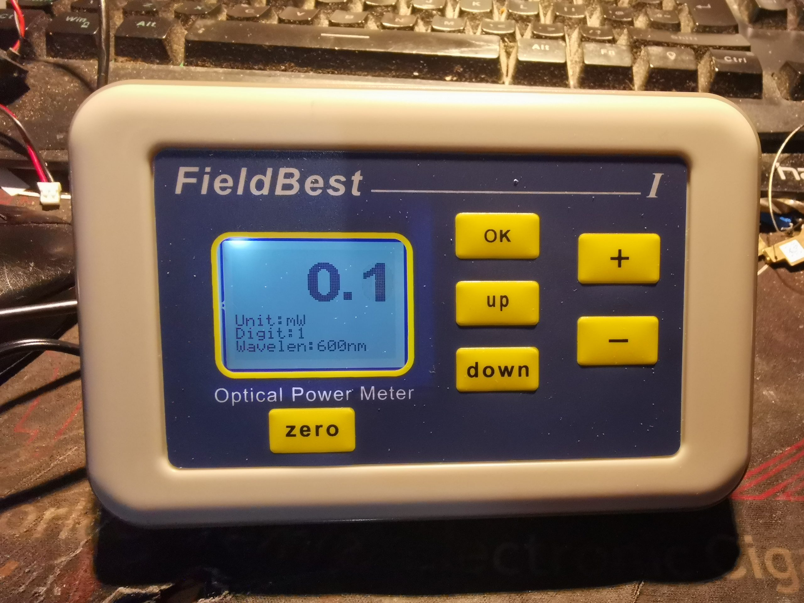
Since I’m building optical power meters at the moment, I figured it was time to see what the Chinese have to offer in this department, and these meters were on offer over on AliExpress, at over 50% off. This is the Fieldbest I meter, and I got two versions – the 1mW-2W & 10mW-50W model, with thermopile sensors. A graphical LCD provides the user interface, and there is also USB serial present for logging to a PC with software. These units appear to be made by a company called “Fastlaser Tech”, but I can’t seem to find much about them.
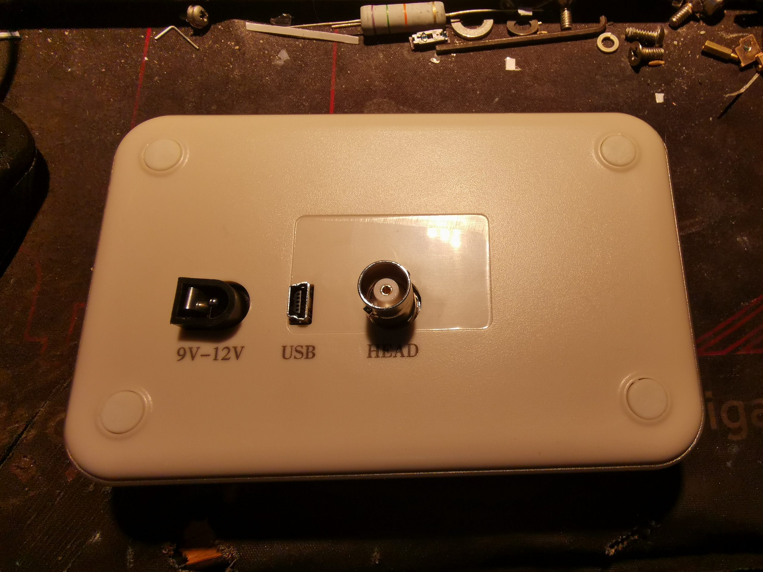
The rear panel has the power input, USB & the signal connection on BNC from the sensor head.
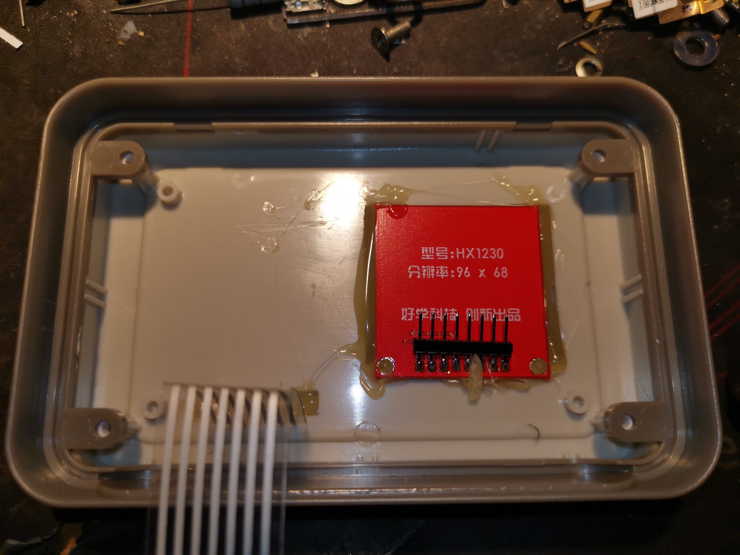
Inside the front cover there is a standard HX1230 LCD, and the flex to the front panel buttons. The LCD itself is rather roughly hot-glued in place.
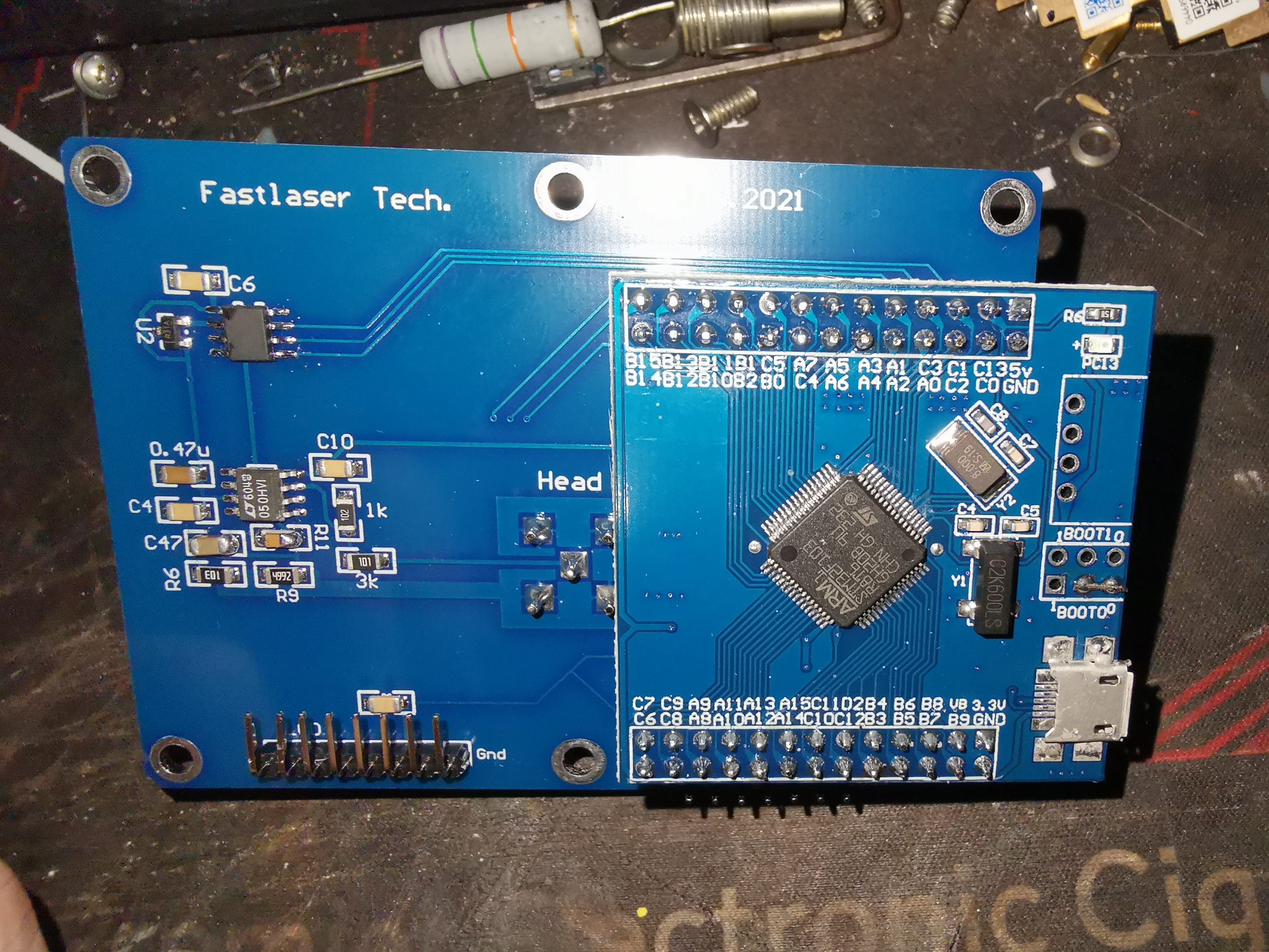
The PCB stack normally sits inside the rear cover, ans holds all the electronics required to run the meter. The main microcontroller is on a separate daughterboard, and looks a lot like a dev board! The input stages from the sensor head are on the left hand side of the PCB.
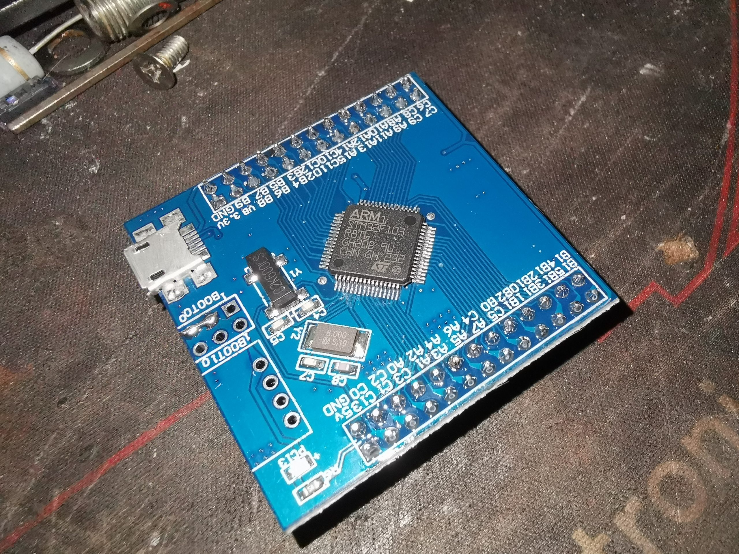
Here’s the MCU daughterboard, hosting the support components for the STM32F107 microcontroller. There’s a USB port on this board too, not sure what that one does yet.
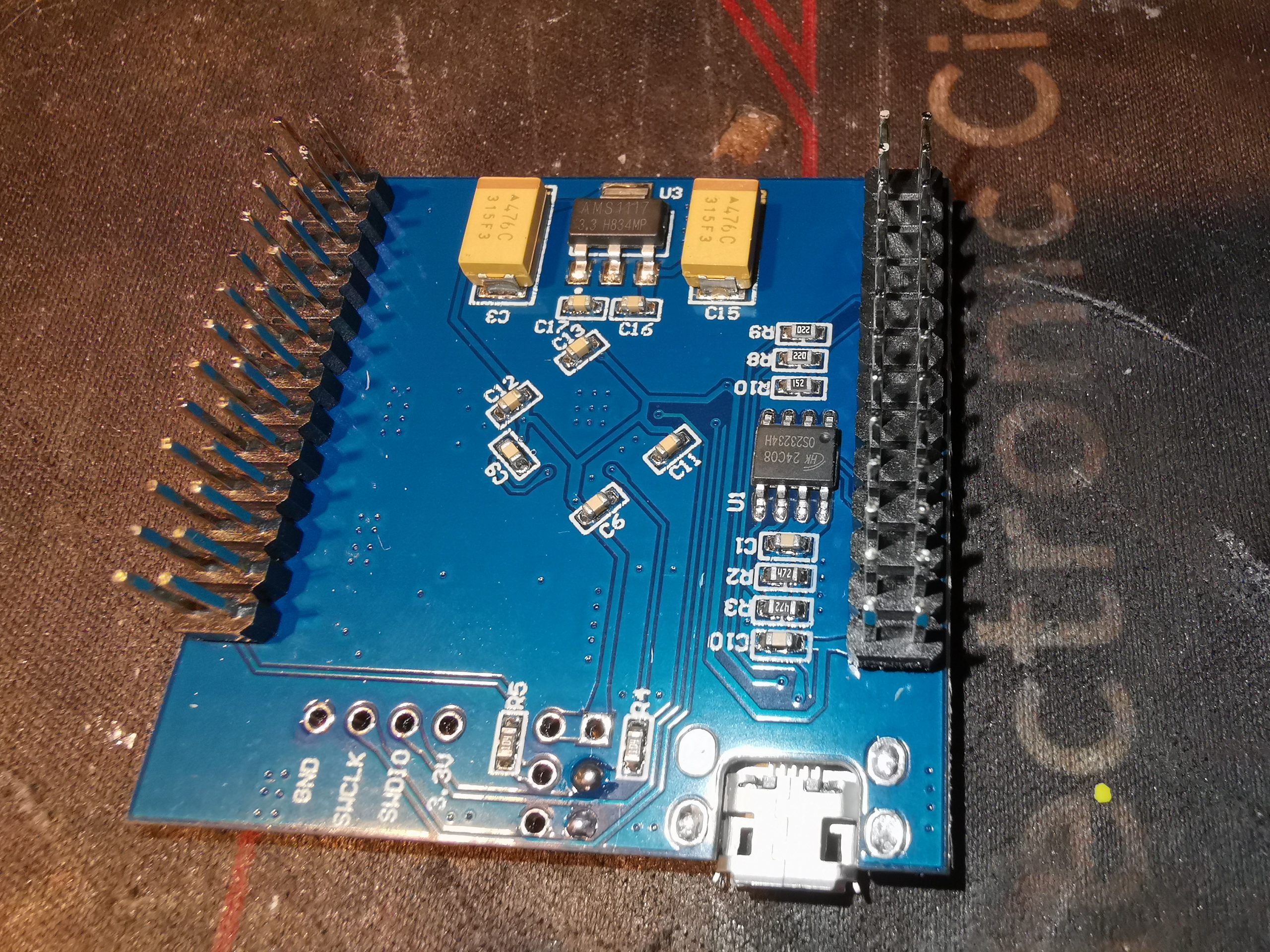
Here’s the other side of the PCB, with a small EEPROM, and voltage regulator. The programming pins are on the bottom left.
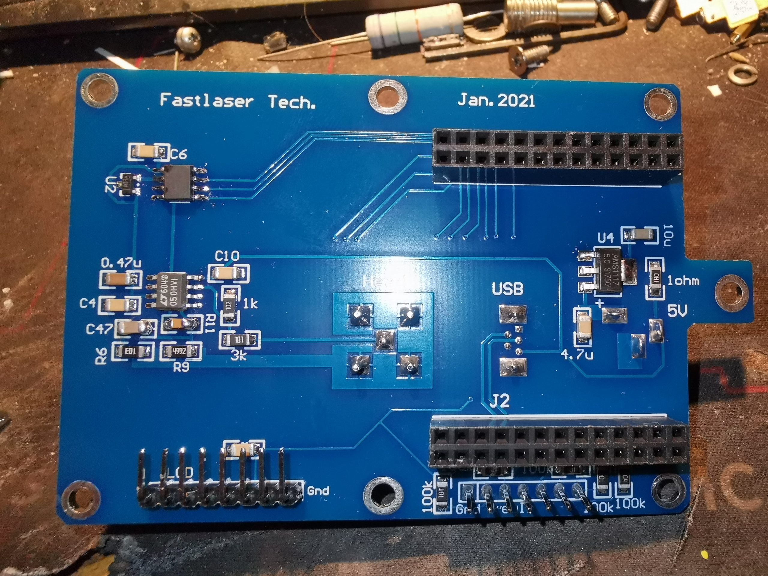
Here’s the mainboard without the MCU daughterboard. Not much on these boards, very sparsely populated indeed!
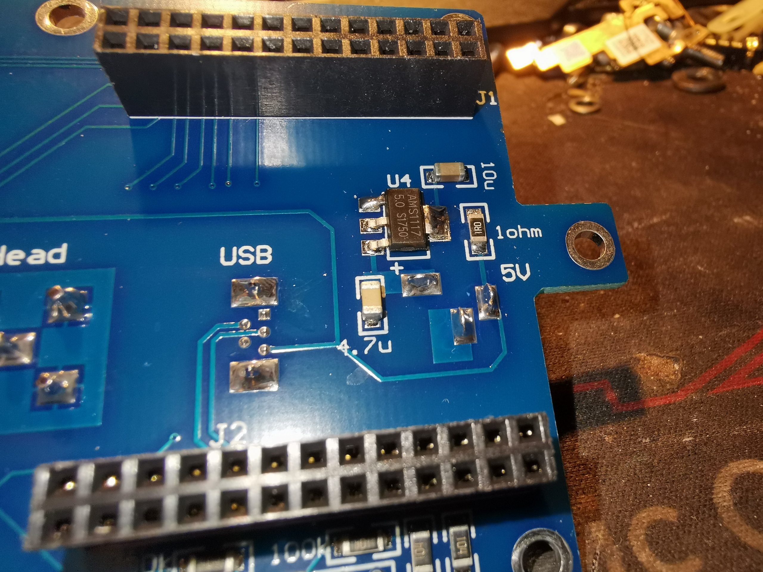
There’s a AMS1117-5.0 regulator on the right, which takes the 9-12v input from the external PSU down to a 5v rail, very simple.
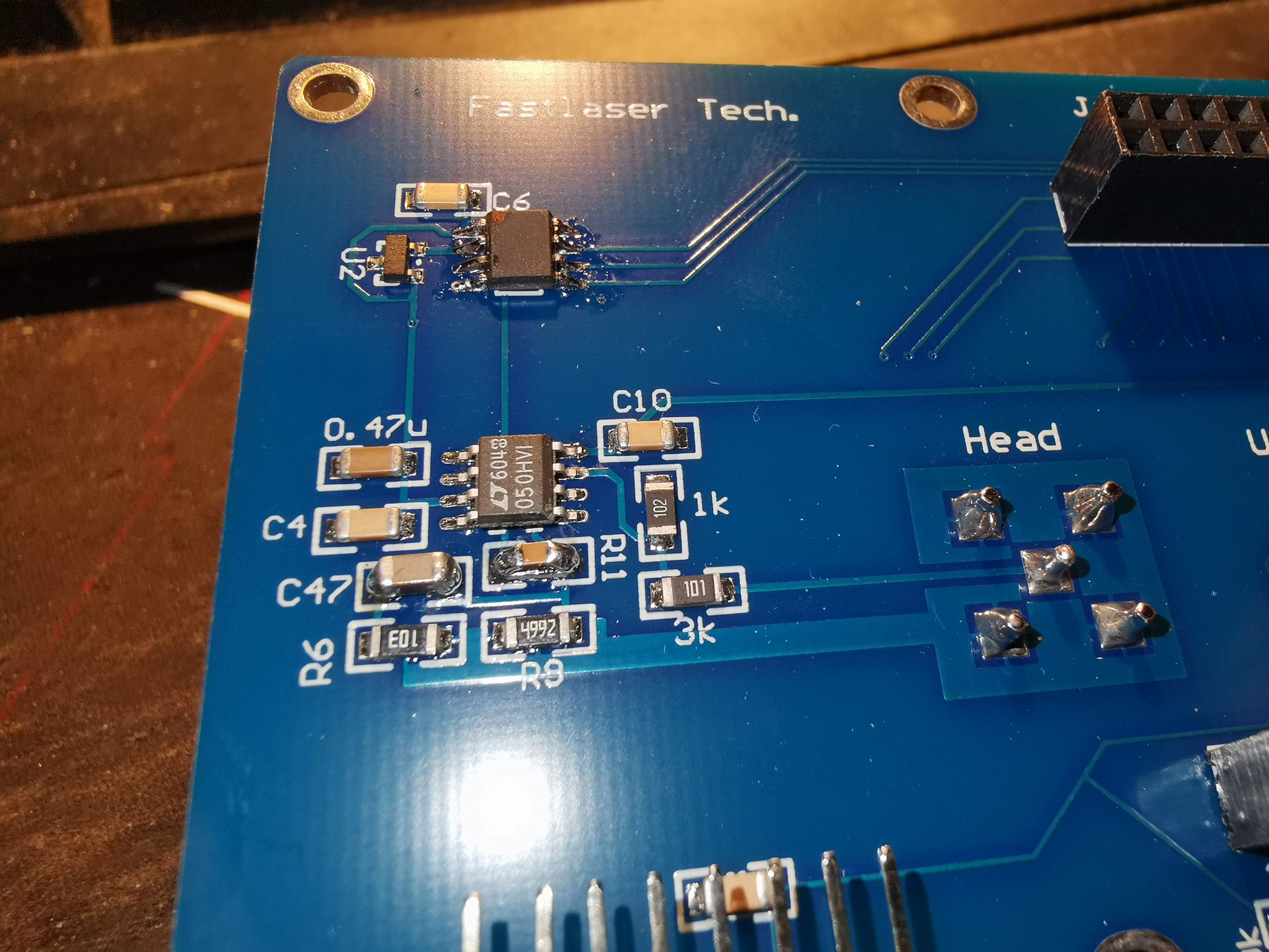
The input stage & A/D converter are on the left side of the board, consisting of an LT6004 dual Op-Amp, likely configured as a transimpedance amplifier, and a small A/D converter, which has had the number scrubbed off. It’s been said many times before that this is pointless, as it’s not too difficult to work out what parts have been used. In this case, everything matches to the LTC1286 12-Bit successive approximation sampling converter from Linear Tech, and it’s being controlled via SPI from the main microcontroller. A TL431 in a SOT23-3 package handles the need for a local stable voltage reference.

Are there any operating instructions for this laser power meter? If so, can you provide the link, etc.?
Thanks
https://www.aliexpress.com/item/33001404531.html
That’s the dev board…
Did you ever dump the code to see how the code works? it would be interesing to see
Unfortunately I haven’t! Maybe something to put on the list of things to do, provided the micro isn’t code protected!
Hello, I have the field best power meter. I need to send the results to the pc. Is there a software to use with this power meter? I see there is a USB. If anyone knows how to proceed with this, I will really appreciate it. Thanks indeed!