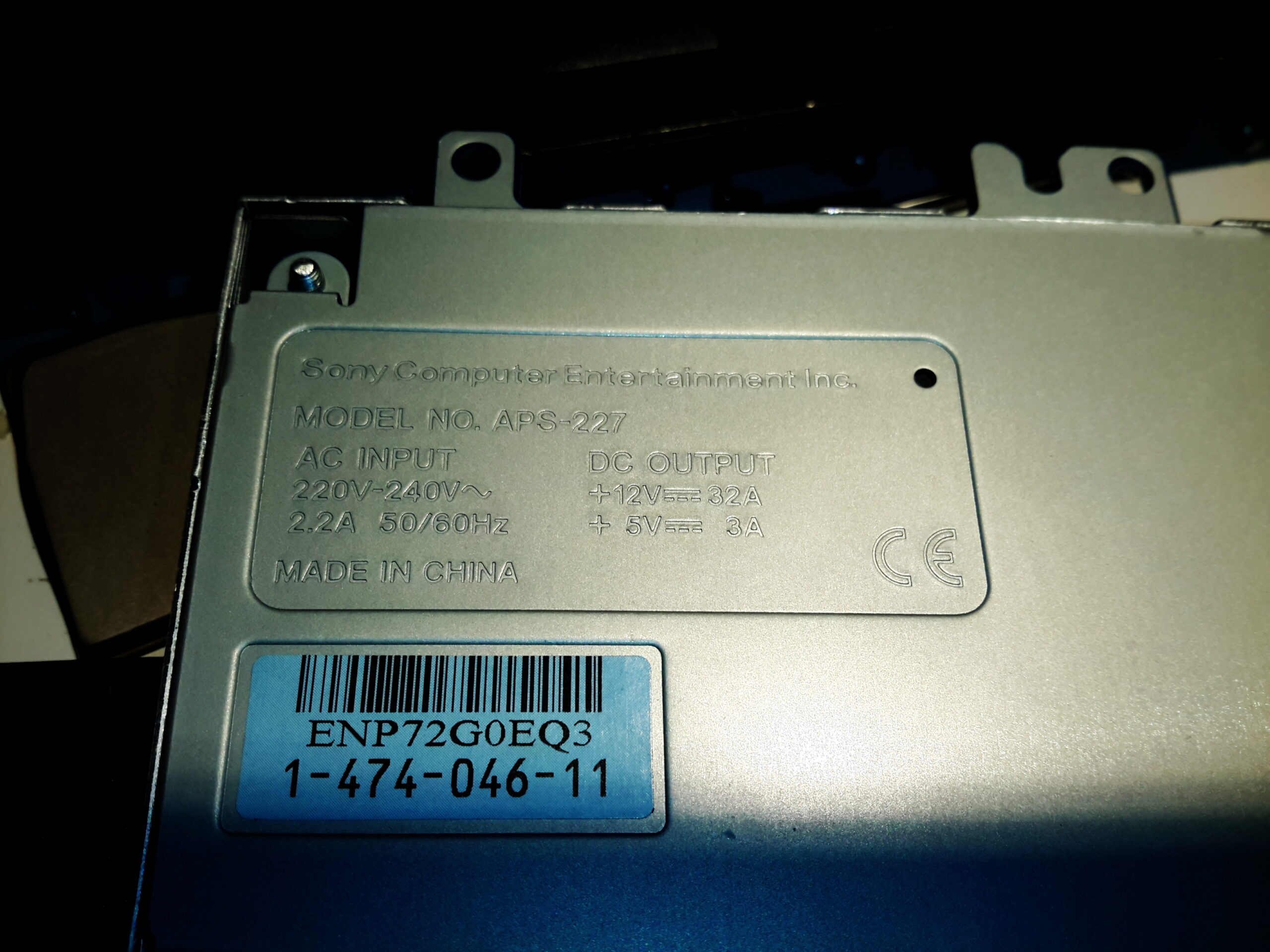
After I did the voltage mod on the APS-231 PSU power supply, I did some reading online & discovered there’s a more powerful PS3 supply – the APS-227. This beast has a 32A +12v rail, with a 3A +5v standby rail.
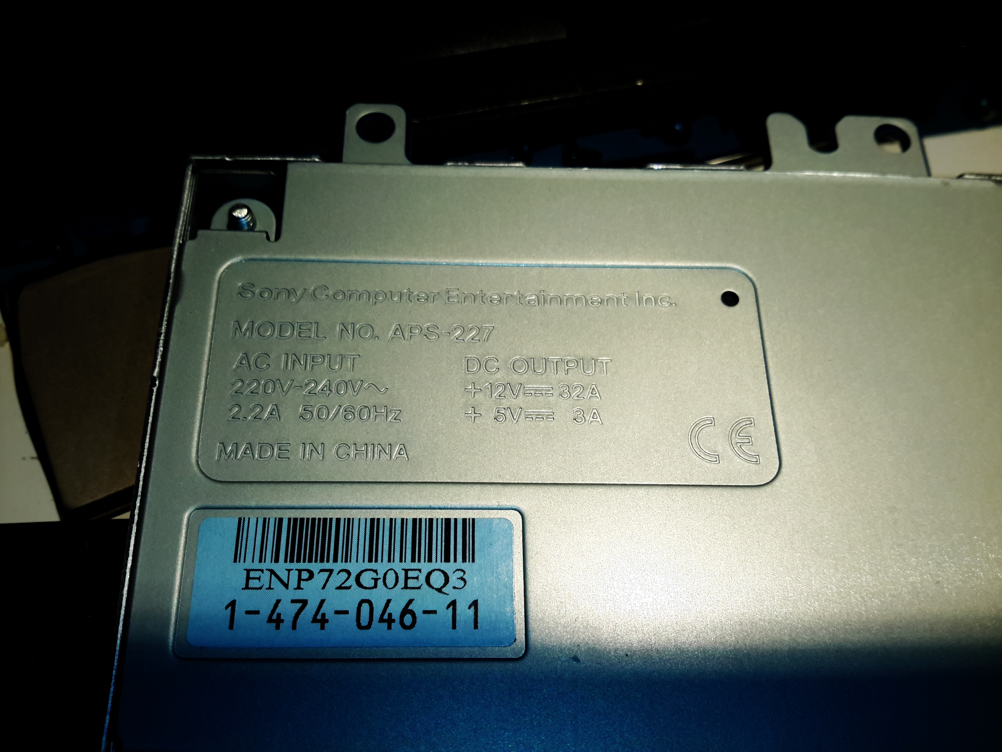
As far as I can tell, these are used in another version of the PS3, obviously with a chunkier requirement for 12v DC.
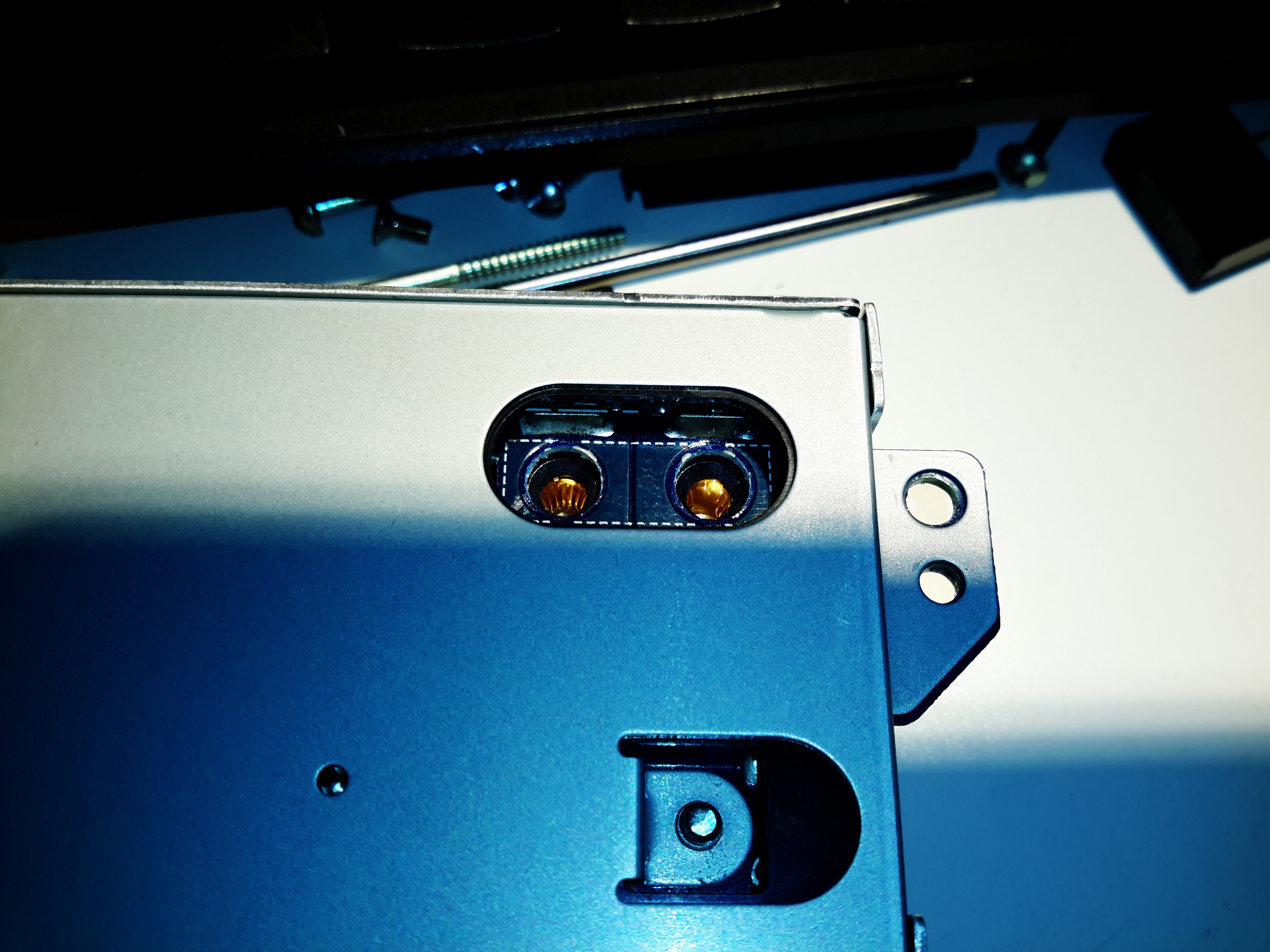
The main DC rail appears through the same type of connector as the smaller supply, which is compatible with standard banana plugs.
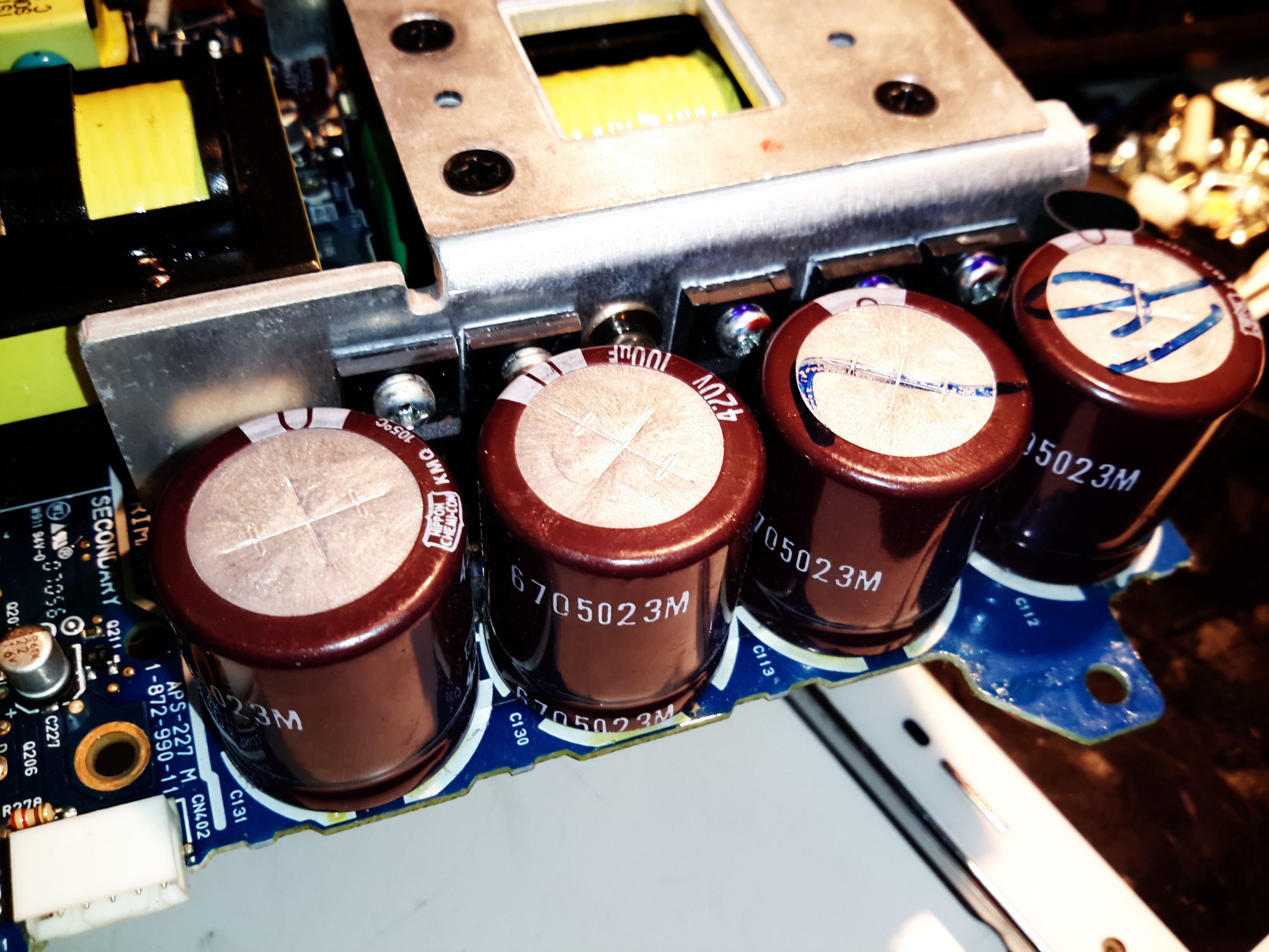
These PSUs are very high build quality, Nichcon electrolytics are used all over the place. These are the HV DC rail filter caps, rated at 100µF 420v.
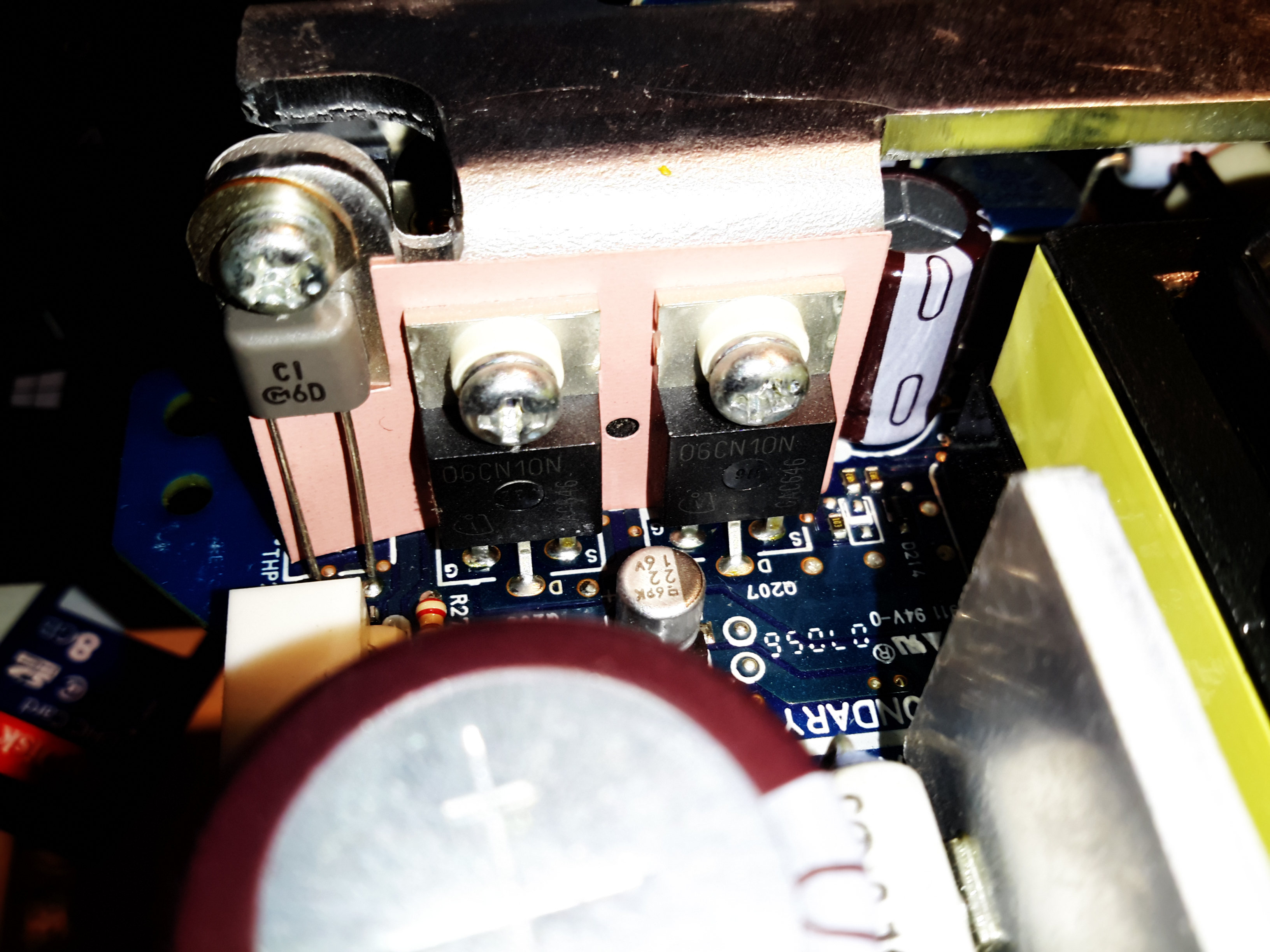
Synchronous rectification is also used in these supplies, keeping the waste heat down to a minimum on the output rectification. There’s a thermistor on the heatsink to the left for the thermal protection.
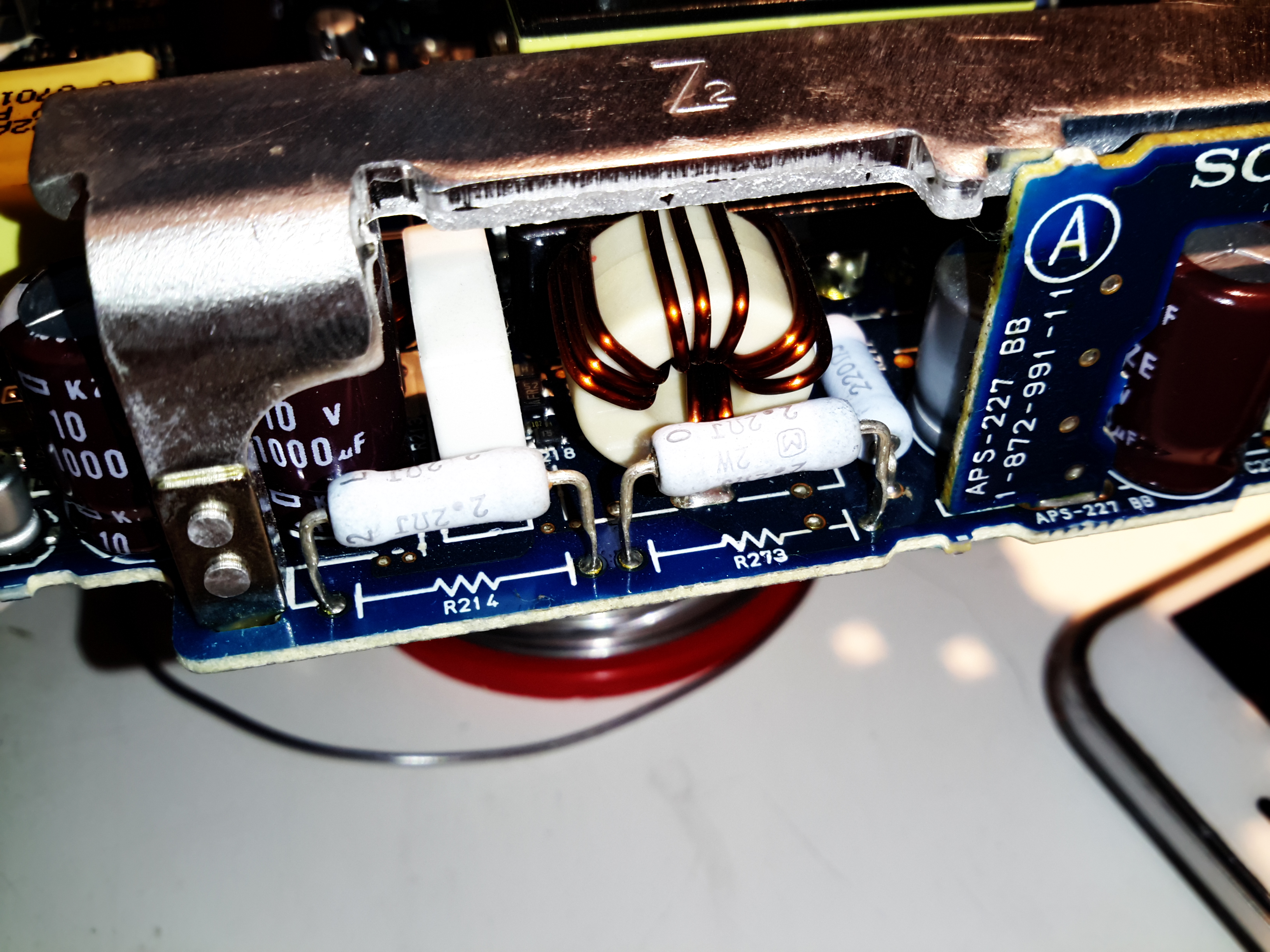
A couple of 2.2Ω resistors in series provide a minimum load to the PSU to keep things stable at low power. Adjusting the output too high will likely cause these resistors to overheat.

The main transformer has a huge secondary winding, only 4 turns of Litz type wire, about 5mm².
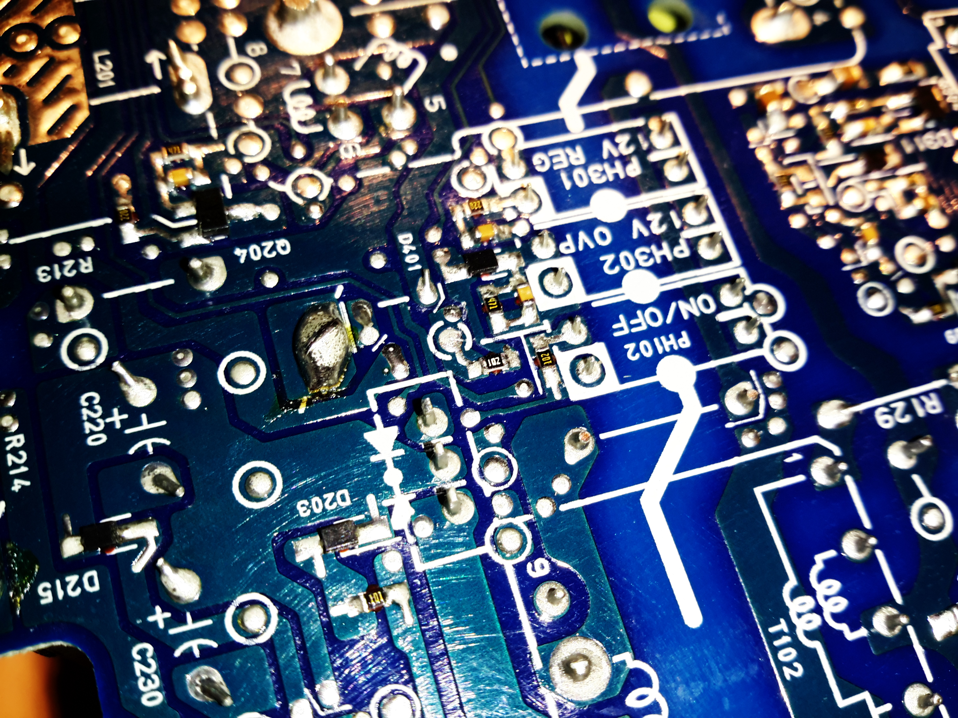
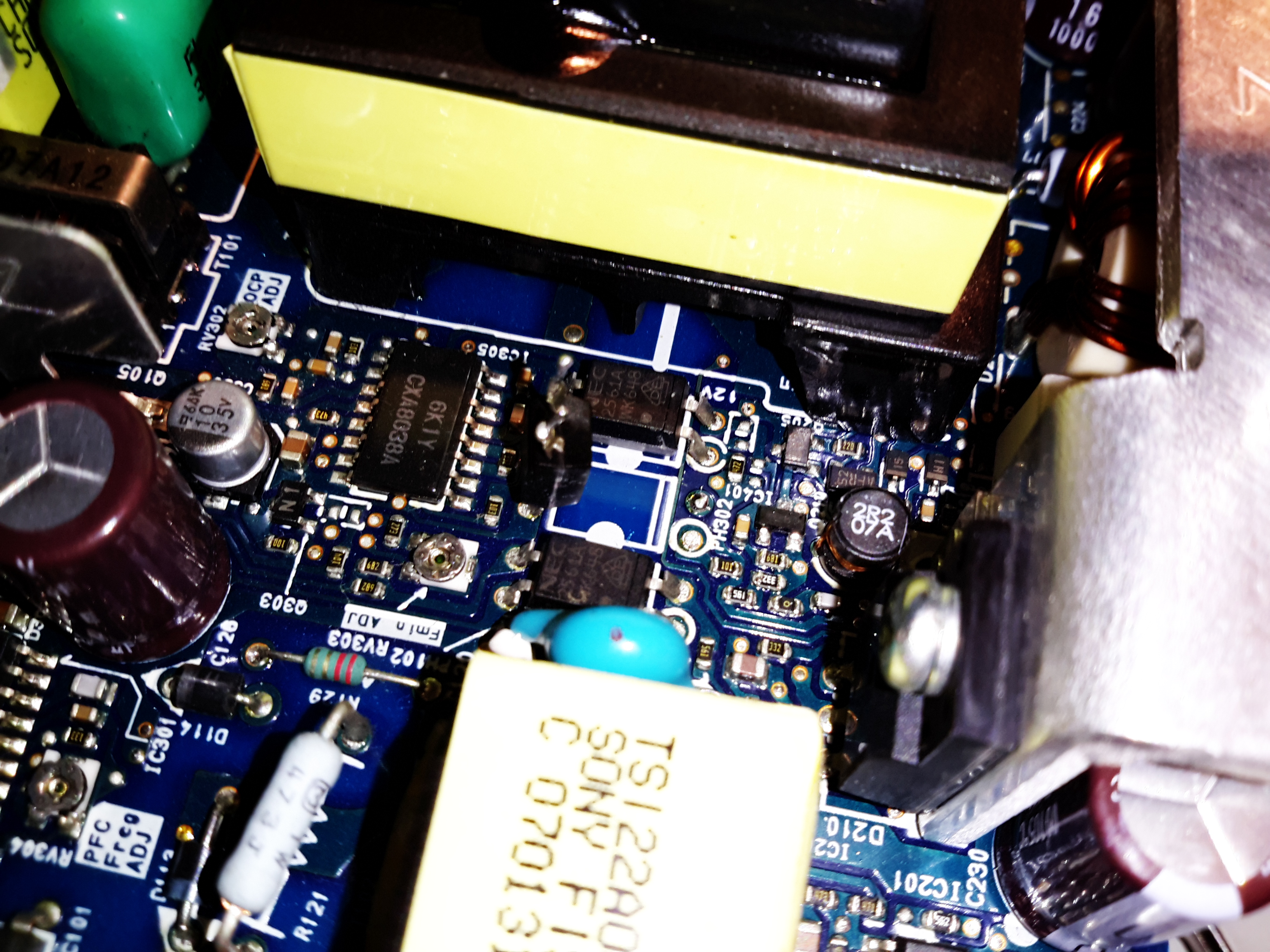
Here’s the point where the mod needs to be done – the same as the other PS3 supply, a single resistor needs changing for a potentiometer, it’s the 1KΩ one in the center of the photo. (White “102” text on the top, unlike the others which are yellow). Desolder this 0402 resistor.
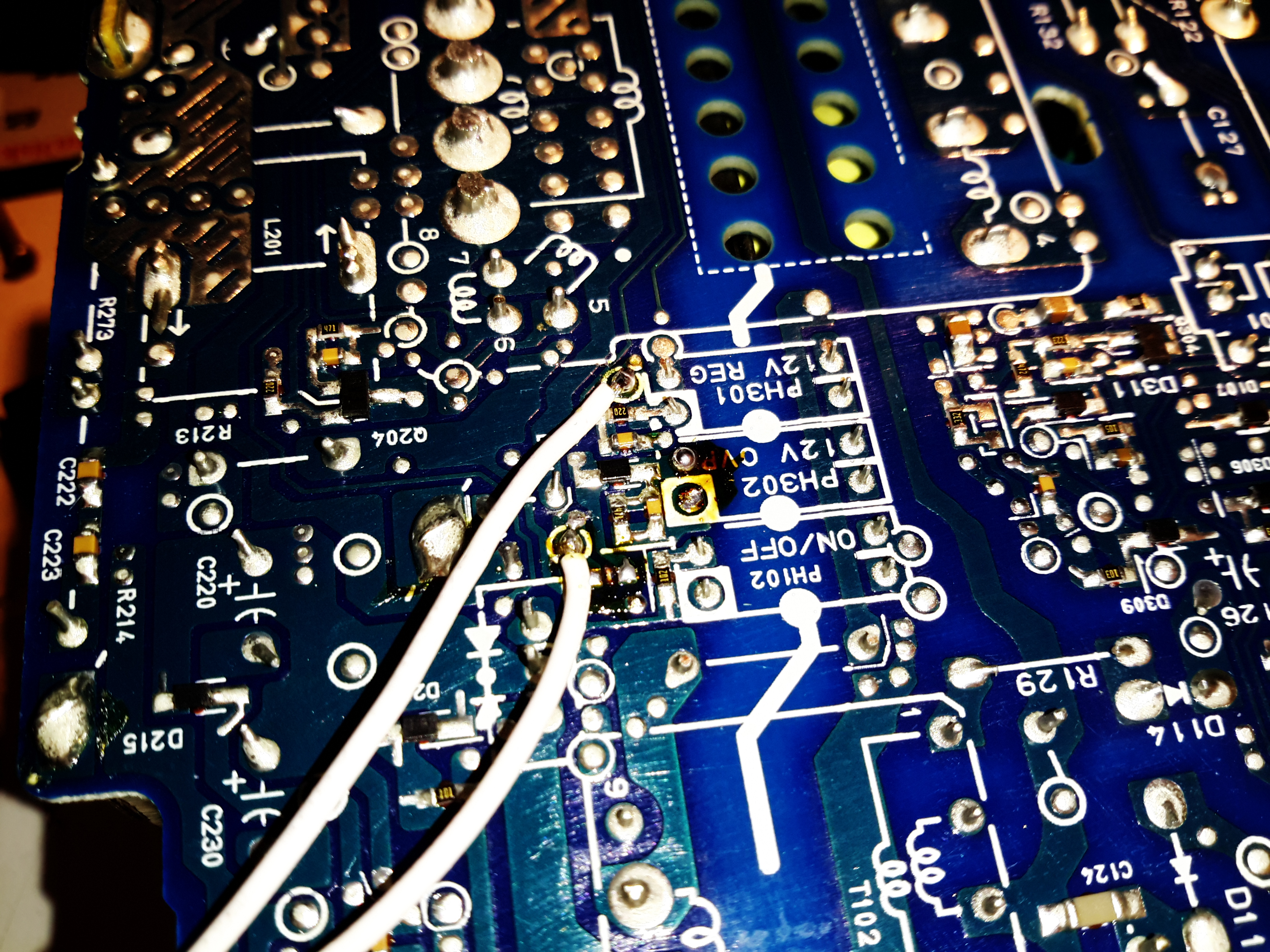
After the resistor is removed, solder the mod wires to these test points.
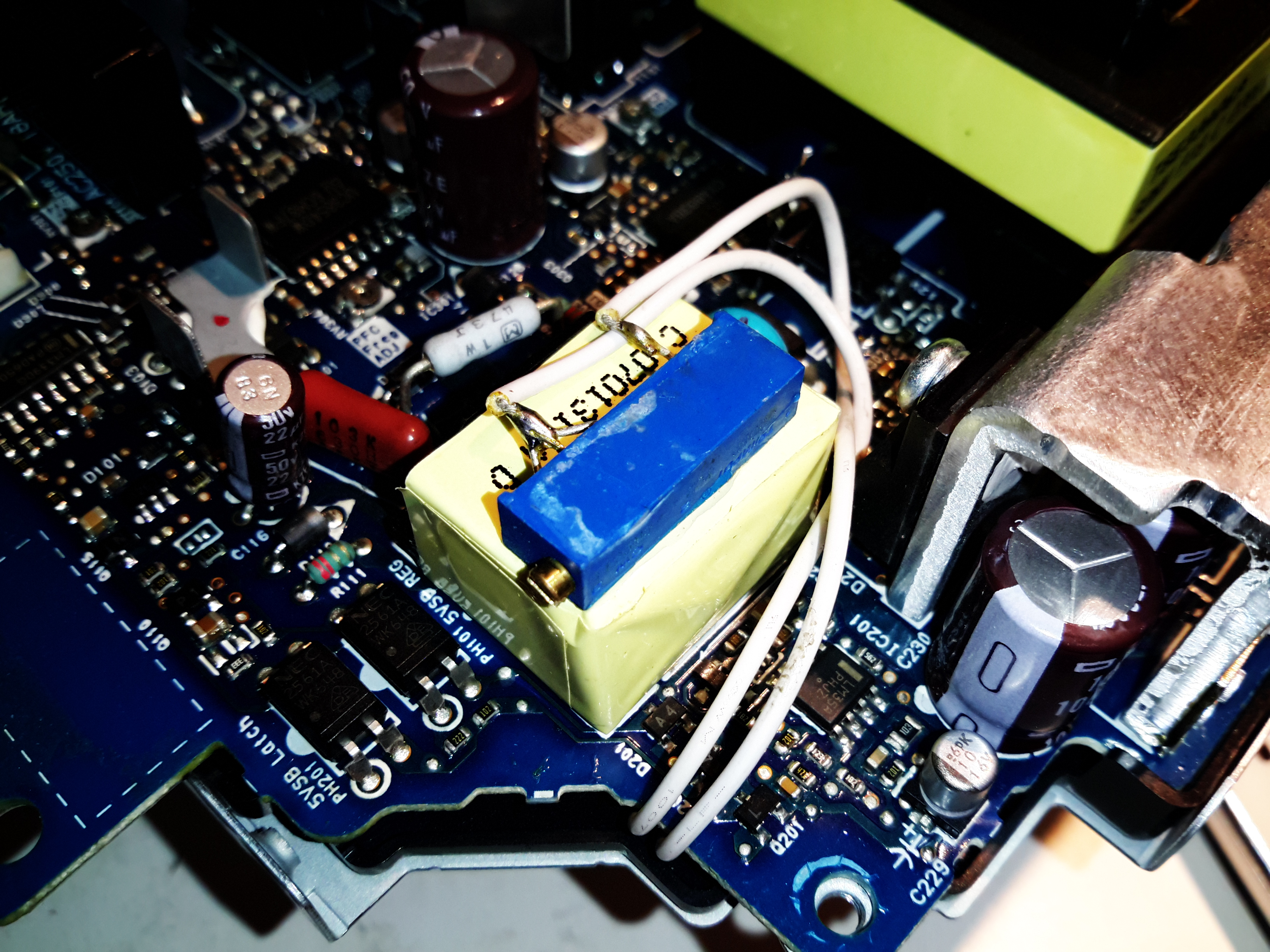
Just like the APS-231, a 1KΩ 18-turn potentiometer is used to tweak the voltage. I’ve secured it with a drop of CA glue to the top of the standby transformer.
The overvoltage protection on this supply is a little more aggressive – tripping things out at 13.4v. However it’s easy to defeat this on this particular supply, by disconnecting the “12V OVP” optocoupler from the secondary side. This does leave the supply with no active overvoltage protection, so be careful on how far the voltage gets tweaked up! The output electrolytics are rated at 16v, so there’s the potential for ballistic capacitors if things are tweaked too far!

Hello im playing with a ps3 psu the same u have here and i wos wondering how much is the max voltage u can get out of it i just can take it up to 23v but i dont know if i can take it a bit more loke 26v thats whot im looking for and one more do you know if i can take the 5v up to 12 or near? Let me know pleas
Hi Marcelo,
The output electrolytics are not rated for 26v, only 16v. Increasing the output voltage to anywhere near 20v would result in the electrolytics exploding. The rest of the supply likely won’t like being driven that hard either, even if you replace the output electrolytics. I’d suggest a purpose-built 24v chassis supply.
Cheers for reading,
de 2E0GXE
cant one simply change component for overvoltage. if it is a zenerdiode there one could change vaule to say 14,4v ?
Hi there.
Nice blog mate.
I have a question before i start hacking the PSU.
Is there any way to adjust the OVP threshold voltage to about 14v or 15v?
I still need the OVP feature and want to have a 14-15v voltage output.
Thanks,
Hi Goen,
I didn’t investigate the OVP circuit, but as far as I remember it’s possible to tweak the voltage to 14v without modification there. I didn’t go higher than this due to the output electrolytics only being rated to 16v.
It’ll be on one of the other optocouplers though, so some tracing might give you the information you need there.
Thanks for reading!
de 2E0GXE
https://www.elektroda.pl/rtvforum/topic2063753.html
Zener D401 13v exchange for15V
How about aps-226
Hi
Do you have a datasheet Form the CXA8038A?
I want to modify a CISCO CAC-4000 down to aproximately 20V.
This powersupply uses two CXA8038A. One to produce 42V @90A an the second for 12V@12A.
I only found a small sheet to the CXA8038P. But also without any applications.
Can you help me?
Regards Armin
Hi Armin,
Unfortunately not, Sony keeps it’s datasheets under lock & key I think. I’ve not managed to ever find much info about Sony-manufactured ICs.
Why if modified more than 13.6v without load the transformer hear vibrated, but if conect to load normal? How maximum voltage can upgrade (capacitor i use 50v)
The PSU’s control loop is likely not designed for this kind of modification, the transformer singing when under no load is a sign of an unstable control loop causing an oscillation. I don’t know how high these units can be pushed before they fail, even with 50v output electrolytics.
please help me with eadp 300ab please
Hi Kit,
I’m not familiar with that supply, but it appears to be built similarly, so it should be relatively easy to modify. You’ll need to identify the correct part of the control loop to tap into. Unfortunately without a PCB in front of me to analyse that isn’t something I can do for you!
Cheers
i wonder if you can help me with LSEB1254A1..
Hello, I have read this and other forums in order to assist me in modifying an aps-226 PS3 power supply for use as a cheap 18v power supply for lipo battery charging. I purchased a high power battery charger which is quite power hungry. It will allow for 12v-18v DC inlet voltage and requires a minimum of 60amps DC to output full charging capabilities. I decided to wire two of the aps-226 power supplies in parallel for a possible output of 64amps at hopefully ~18v. I first followed this article and found that connecting a 100k ohm 15turn potentiometer to pin #2 and #3 of the “L287” , described earlier in this article, will allow for an adjustable voltage of up to about 13.4v DC. At ~13.4v DC the OVP circuit will trip shutting down the power supply for about one minute. I have now found that by modifying the input voltage of of the optocoupler for the OVP circuit with resistors in order to adjust the max voltage of the OVP. If you look at the back side of the aps-226 PCB you will find one of the optocouplers labeled “12v OVP”. If you lift the two pins one the secondary side of the PCB and solder two resistors of equal value between the PCB and optocoupler pins you can trick the OVP circuit to think it has less voltage than what truley exists. I ended up using an 1/8watt 260kohm resistor to achieve the voltage I needed. Be sure to upgrade all 16v capacitors to 25v to avoid smoking them. If needing above 16v be sure to also replace all three of the 2.2ohm 2watt resistors on output rail with 2.2ohm 5watt.
Hope this helps somebody, good day
Hello. How do I use aps-227 as a voltage regulator by changing the voltage between 0-20 volts?
Hi Tayfun,
The supply will not operate to 20v stock – you’ll have to modify the OVP circuit as the comment from Rogue above. The output electrolytics will need to be replaced with a higher voltage rating as well, along with the 2.2Ω loading resistors, they’ll need uprating.
This isn’t guaranteed – I don’t know how high a voltage the secondary side components will survive, so you’ll have to experiment & expect to lose a PSU!
Which one the “12V OVP” optocoupler from the secondary side of APS-231? Many thanks.
Hi, i’ve the same psu, and i would like to use as variable voltage psu. I folllow the guide, but in any case, with any kind of trimmer not have a voltage lower tha 11,80v.. Anyome know a way to modify to obtaim 0-15v ? I don’t find any scheme of this psu..
Is increasing the voltage going to increase output current as well? According to Ohm’s law 12v/0.375ohm = 32A so does that mean 15/0.375ohm = 40A?
Hi Overev,
Unfortunately it doesn’t work this way with power supplies – you need to remain within the nominal power rating of the power supply, so the current would reduce with a higher output voltage.
Hi thanks for the guide, after i did the mod it did work, but when it was time for me to change the capacitors it turns on then immediately turns off, could it be a short circuit or something? And yes i have disconnected the protection ics, can you possibly guide me to troubleshoot this issue? Thanks in advance.
oh btw there is indeed 12v output but after less than a second the relay clicks again and immediately turns off
Can you help me, I have a psu like this, but for some reason the 12v voltage drops to 8v when there is a load, the load in question is a monoblock amplifier ,I think the regulatory system is broken and where is the problem?