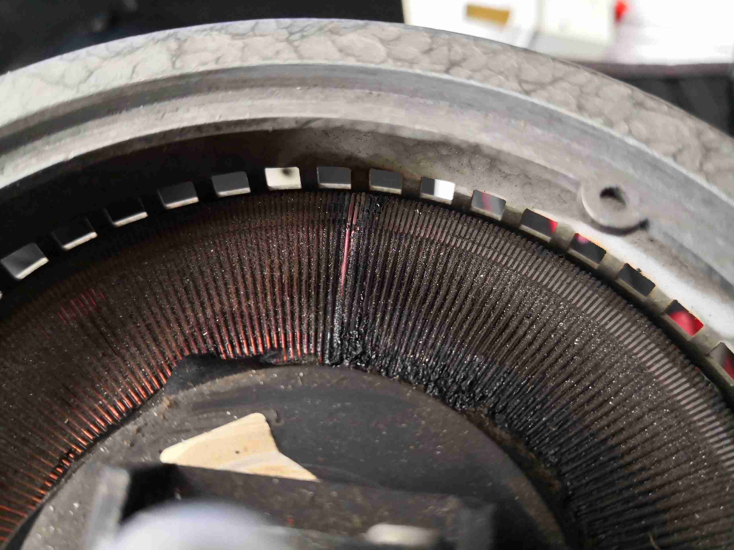
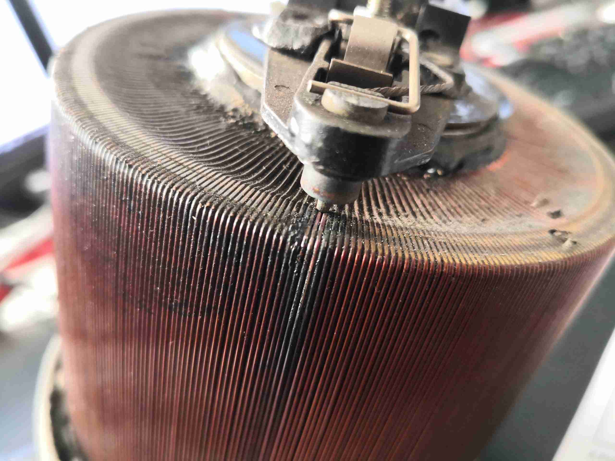
Well, this is what happens when a Variac rated at 3A is subjected to 15A for a while – a complete burnout. The smell associated with this failure was formidable, it’s a shame I can’t convey odour through photos! Above is the burned section of the winding (it was set for around 115v output from our 240v mains).
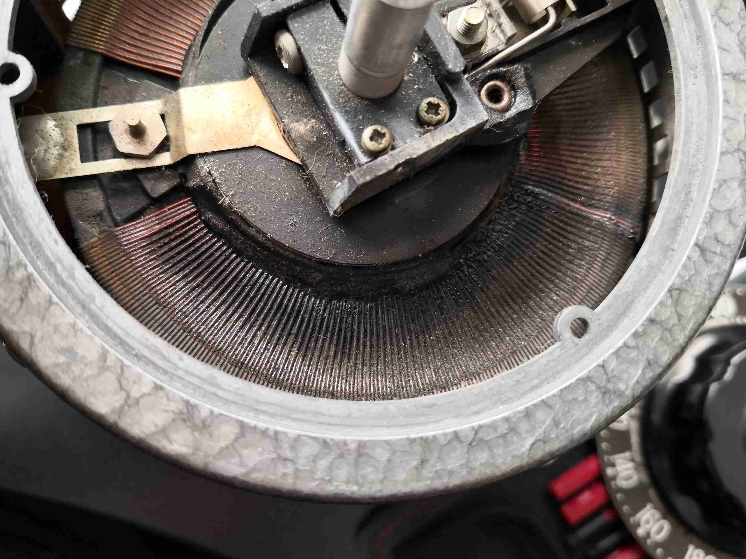
Top Cover Removed
At first the rotor was stuck in position, but a bit of force allowed some movement. The armature holding the brush has melted at the rivets, and the copper tail from the brush is severely heat-discoloured. This got HOT! When brought to me just after failure, it was near impossible to hold onto the outer casing!
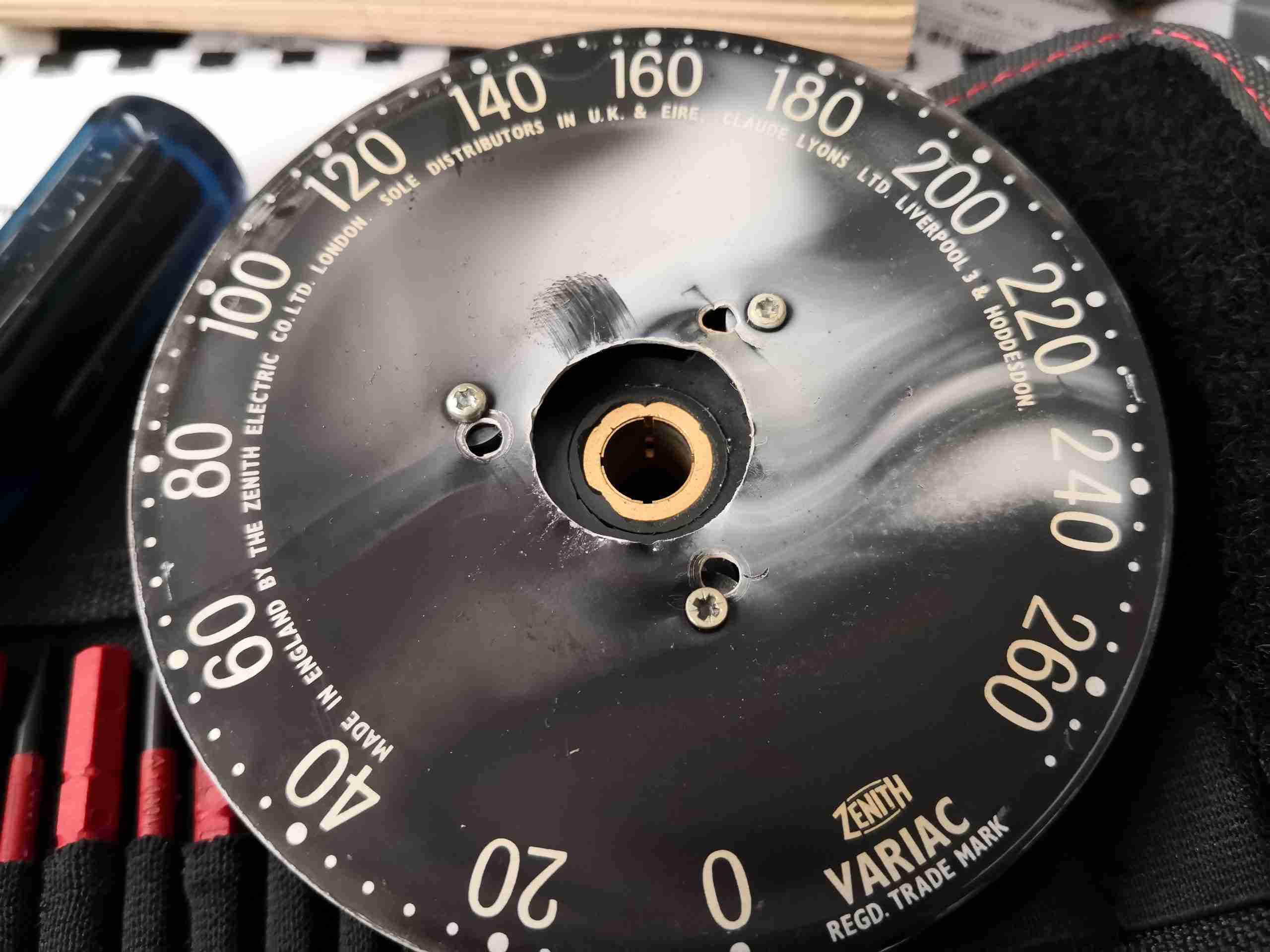
Smoke Residue
Underneath the control knob, there’s white ash, which has evolved from the insulation burning off the windings.
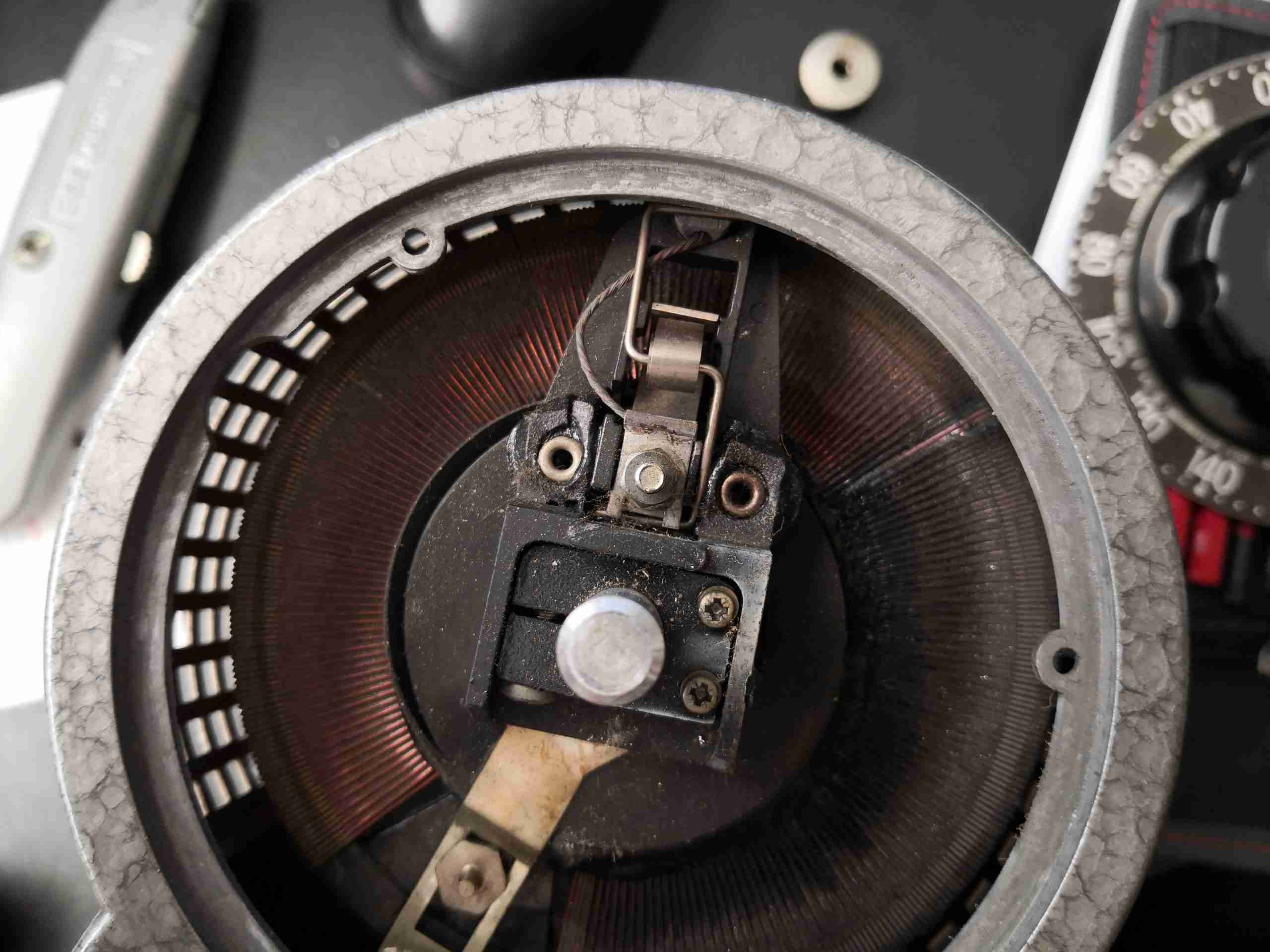
Shorted Turns
A closer look at the point where the brush was set shows the pair of windings have pretty much fused. The worst of the heating occurred here it seems.
Windings
The heating has extended down the windings and the insulation has melted all around the top & base of the toroid core. Unfortunately it’s the end of the line for this particular transformer, and it now rests in the Black Museum of Electrical Death.
These projectors were very popular when they first appeared on the market with the laser hobbyist community, and for very good reason – they contain a massive array of 445nm Royal Blue laser diodes in their optics engine. Originally very expensive, these units can now be had for under £50 on eBay, usually with damaged DLP chips.
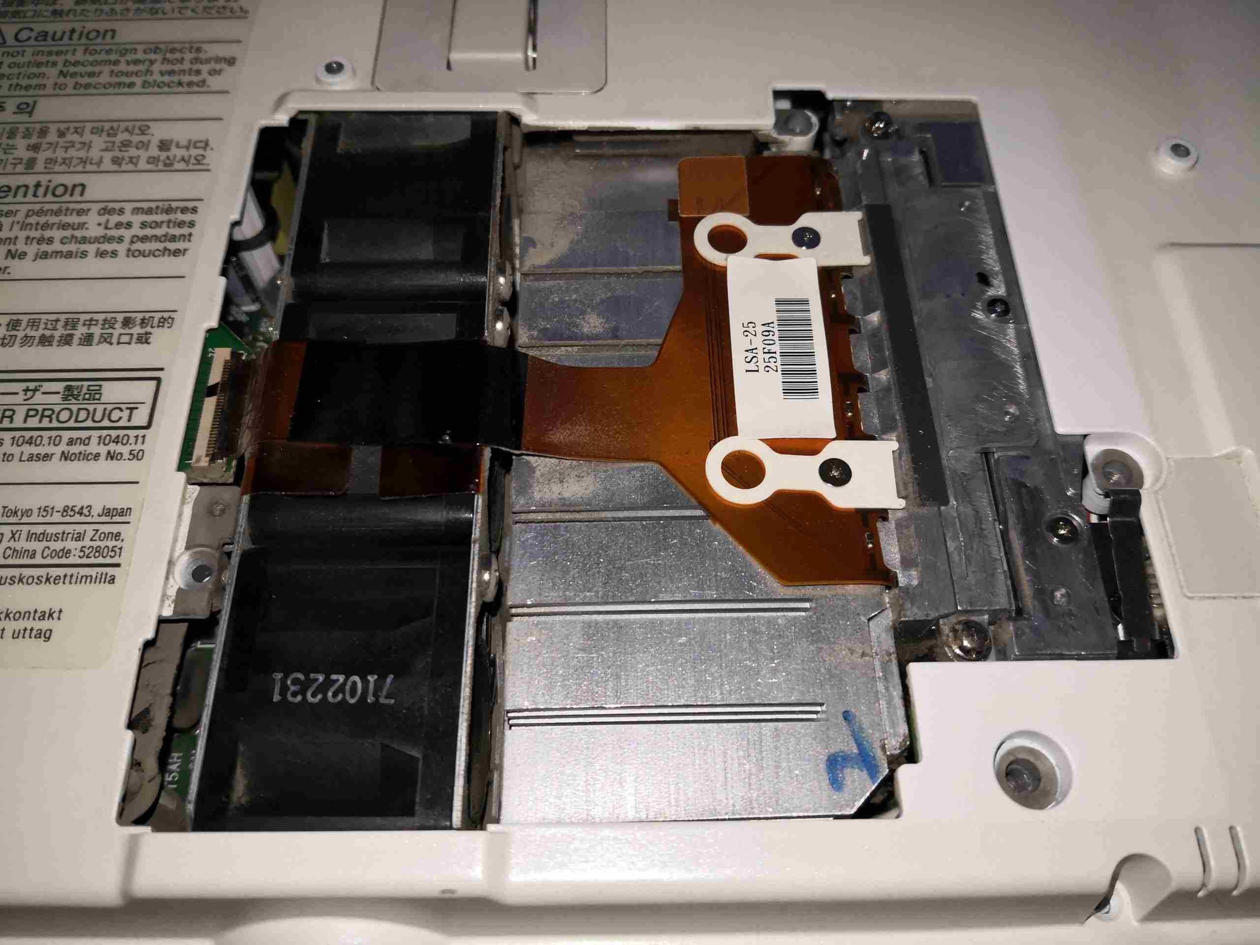
Laser Module Door
Under the door on the bottom of the projector is the 445nm Laser diode array module, itself secured in place with security screws to the beam combiner. The rack of 3 high speed fans to the left draws air over the substantial heatsink.
Top Cover Removed
After removing the shell securing screws, the top cover comes off with the button panel. This gives a view of the internals, mostly PCBs at this stage.
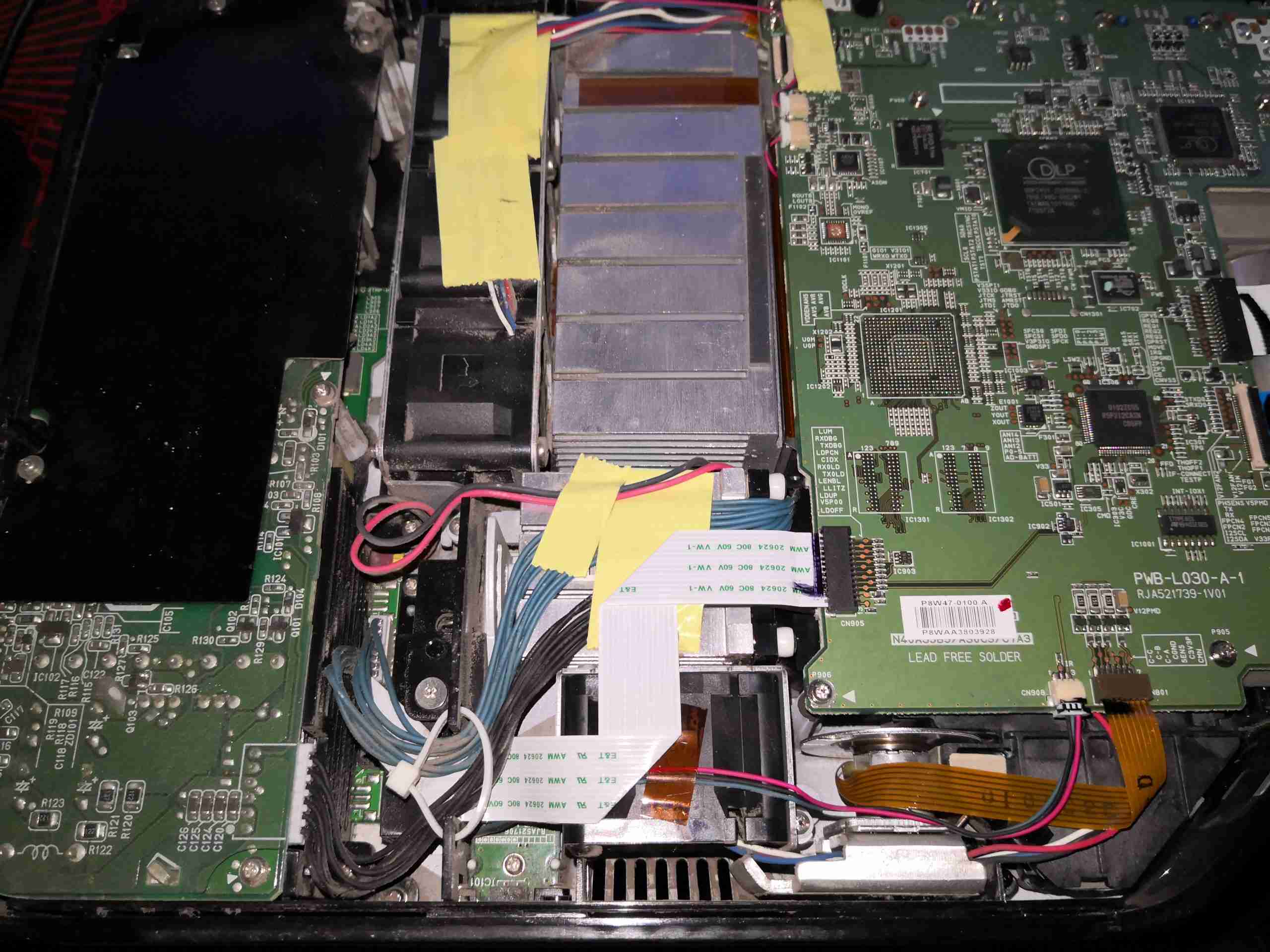
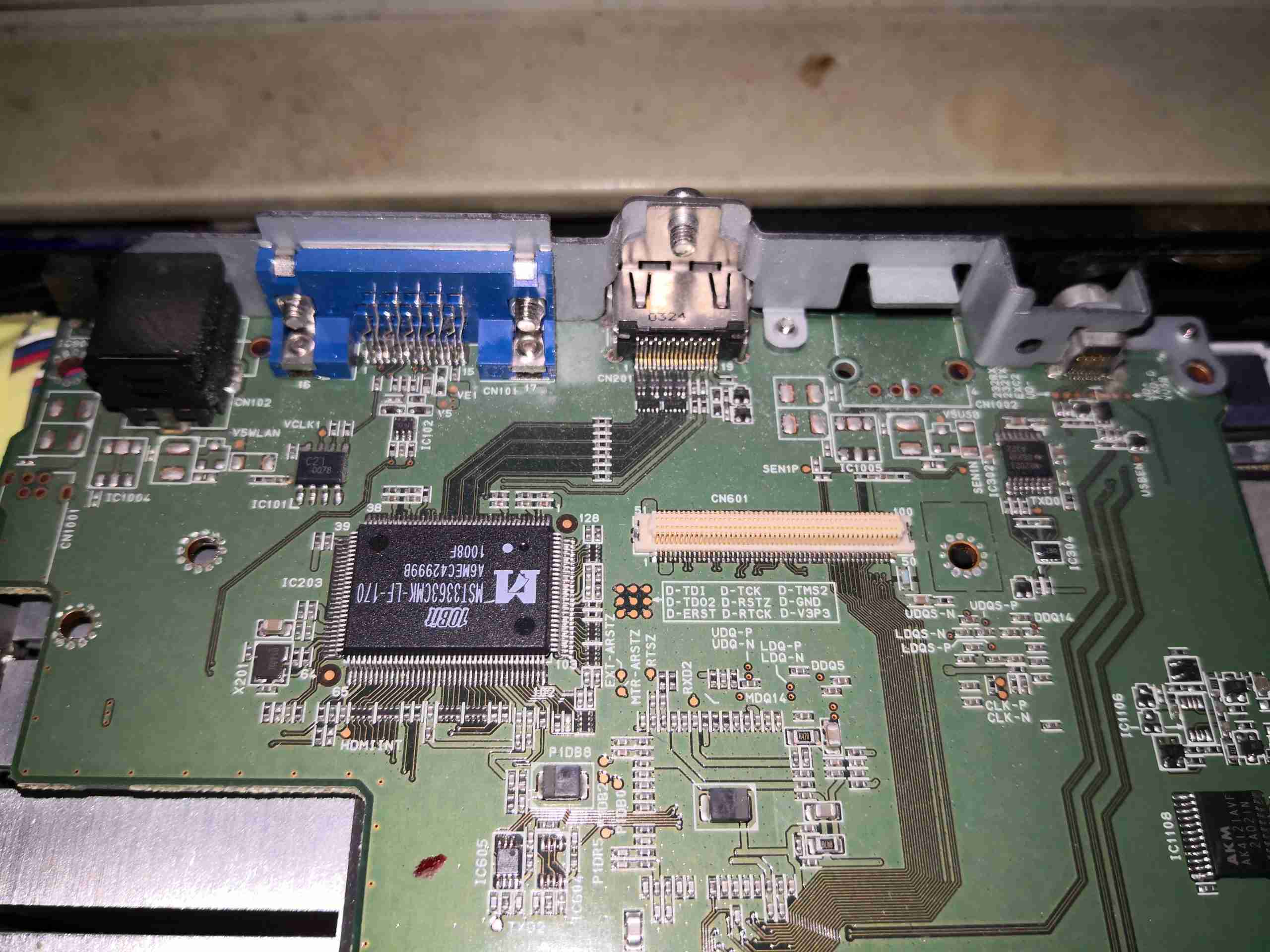
Main Control Board
On the left side of the projector is the main control PCB, with the video handling circuitry.
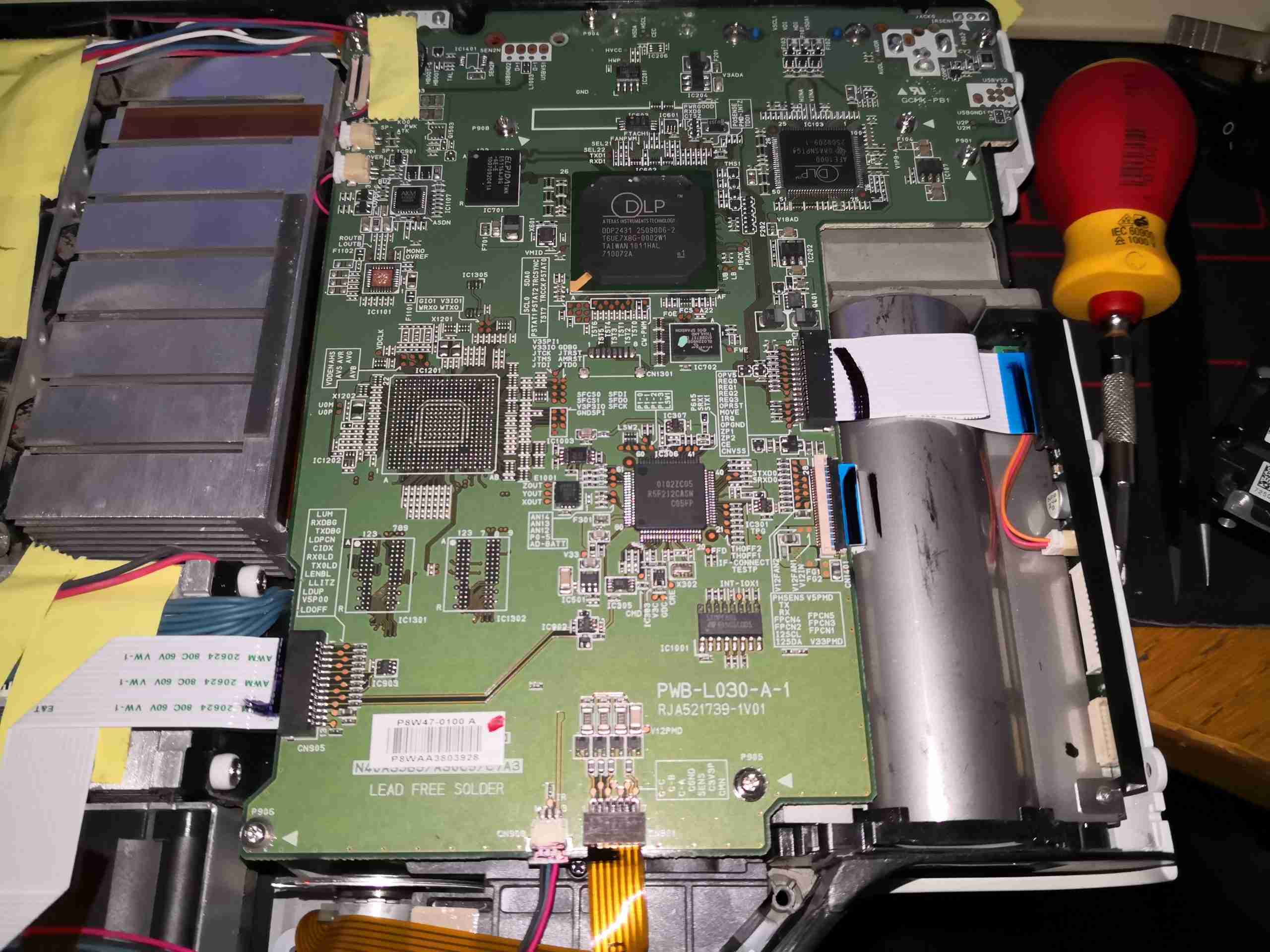
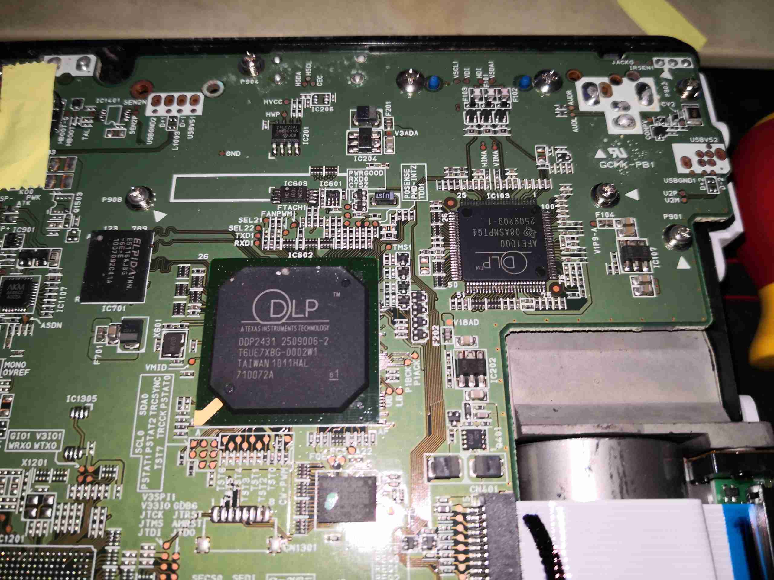
DLP Chipset
At the top of the board is the main DLP image processing chipset, these two components are actually custom parts, so no datasheets are available. The main DLP IC has some DRAM & a Spansion serial flash for firmware storage. There’s also a small audio amplifier on the left to drive the onboard 2W speaker.
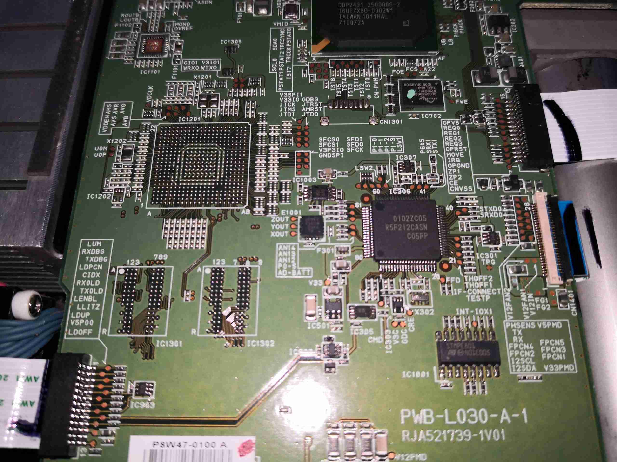
System Microcontroller
Further down the board sees an unpopulated BGA footprint, with more space for DRAM. The main system microcontroller is on the right, a Renesas part.
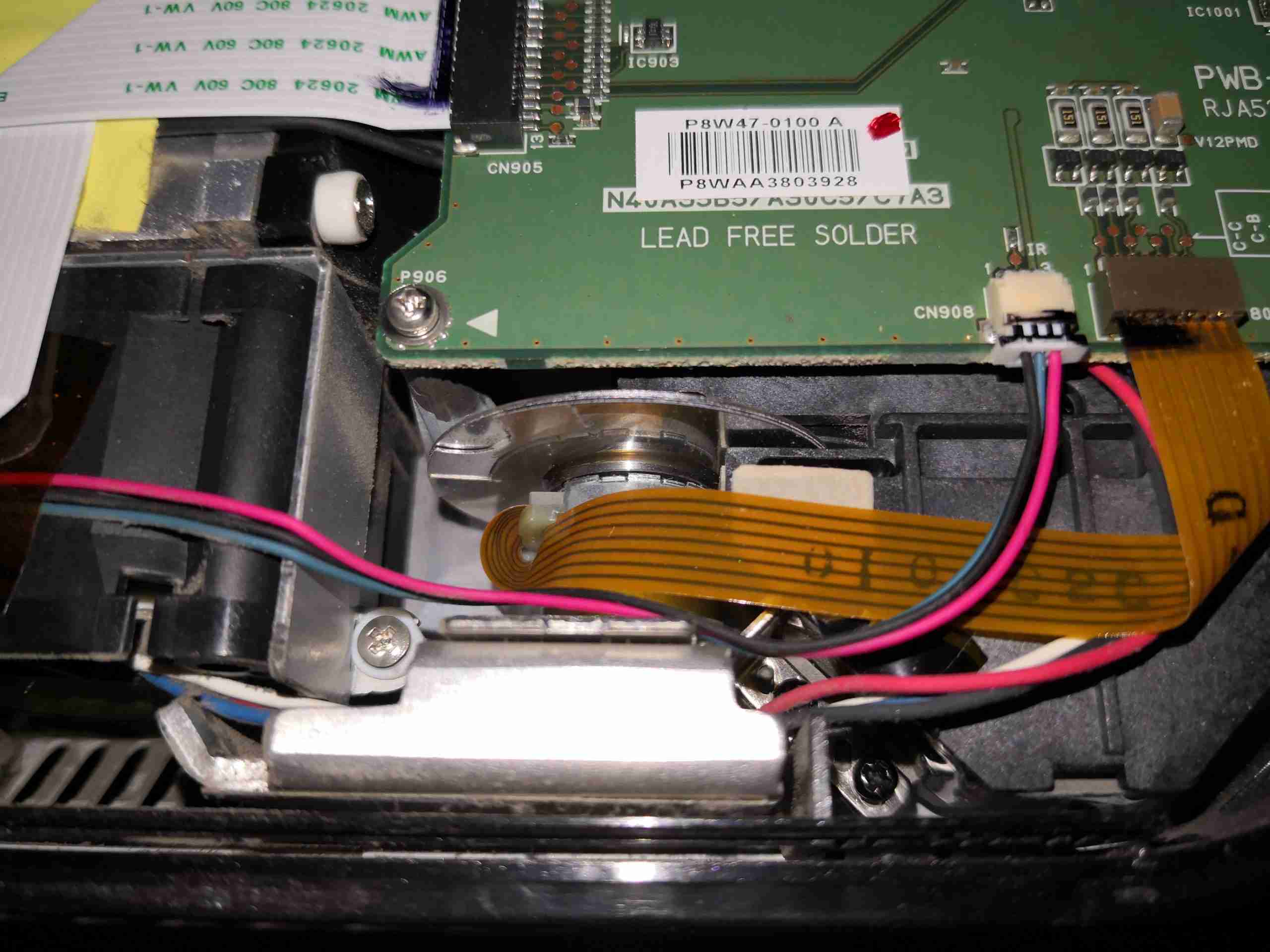
Phosphor Wheel Motor
Right at the bottom edge is the connector running off to the phosphor wheel drive motor.
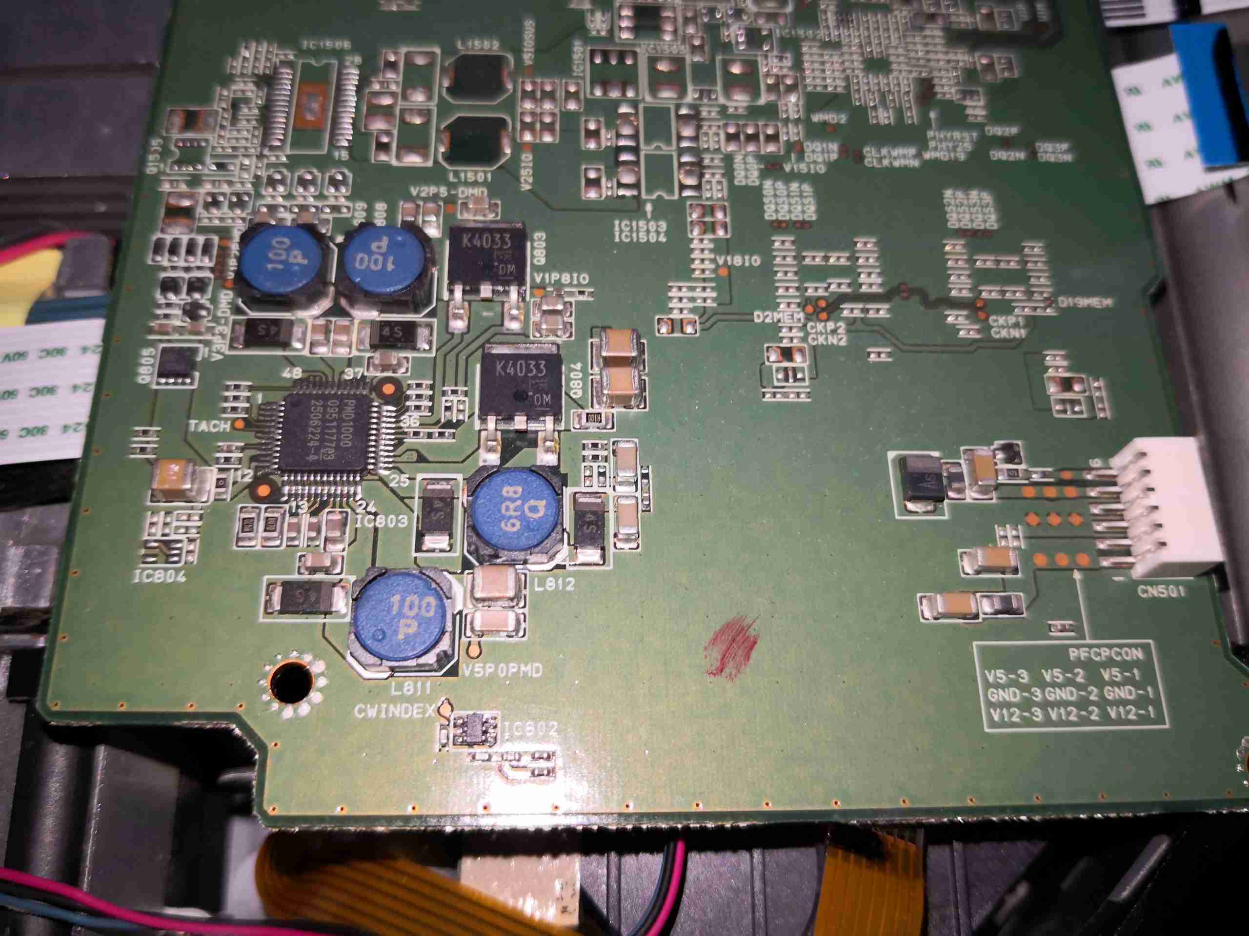
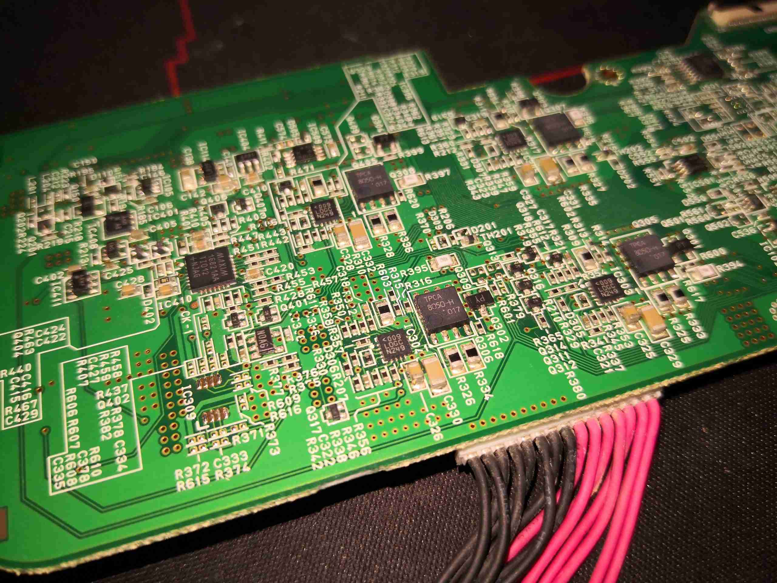
DC-DC Power Management
The reverse side of the board is pretty sparse, there’s quite a few passives & power control. Down towards the bottom surrounded by inductors is the system power management IC, the DLPA100. This takes the incoming DC 12v rail from the connector on the right side of the board & produces several supply rails for the internal logic: 1.1v 1.8v, 2.5v, 3.3, 5v & also contains the 3-phase brushless driver for the phosphor wheel motor. The main control board input power connector also has a +5v from the mains supply, for standby power. The main board signals the PSU to switch on the main +12v rail through a pin on this connector.
HDMI Interface Chipset
The other end of the board just has the connectors, a bit of glue logic & the HDMI interface chipset.
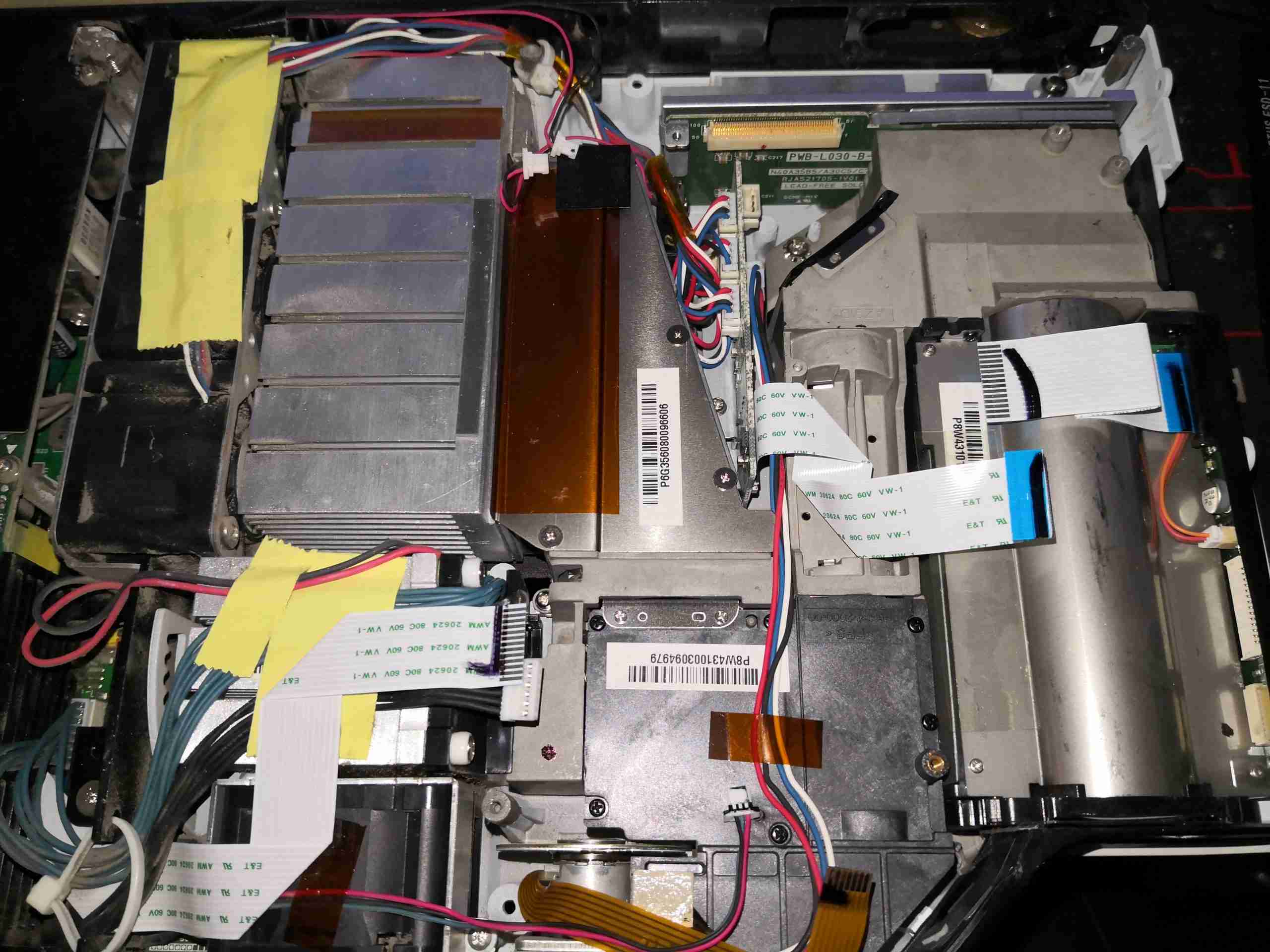
Main Board Removed
After unplugging all the connectors, the massive cast frame of the light engine is visible.
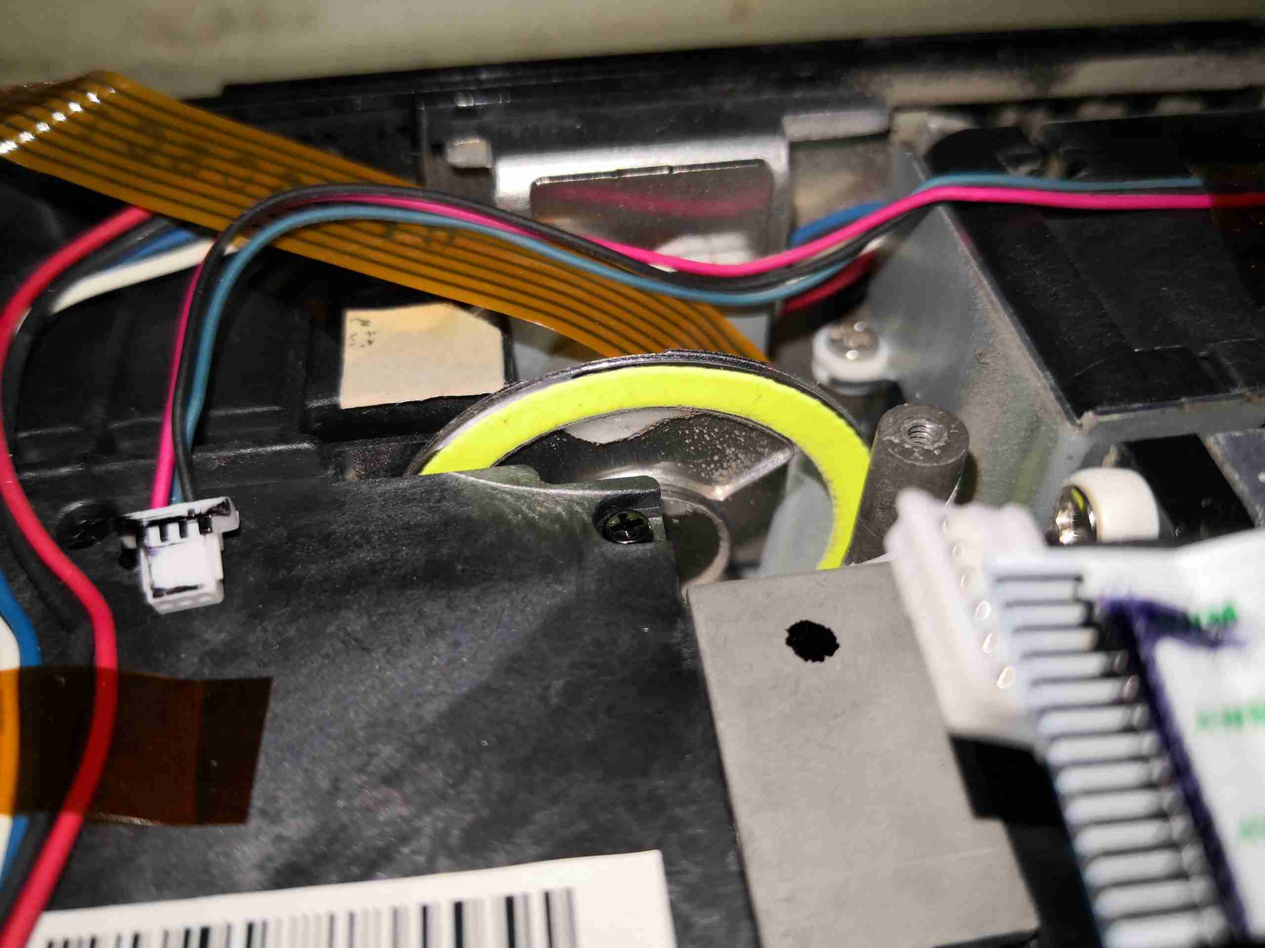
Phosphor Stripe
Here’s a closeup of the phosphor stripe around the edge of the wheel. This takes the 445nm light from the laser module, and converts it into green. There’s also a frosted glass section of the wheel to pass some blue for the image. The reason for the phosphor being in a large stripe on the wheel is load spreading – there’s several watts of optical power focused down to a very small spot on this phosphor, and would overheat quickly if it wasn’t moving.
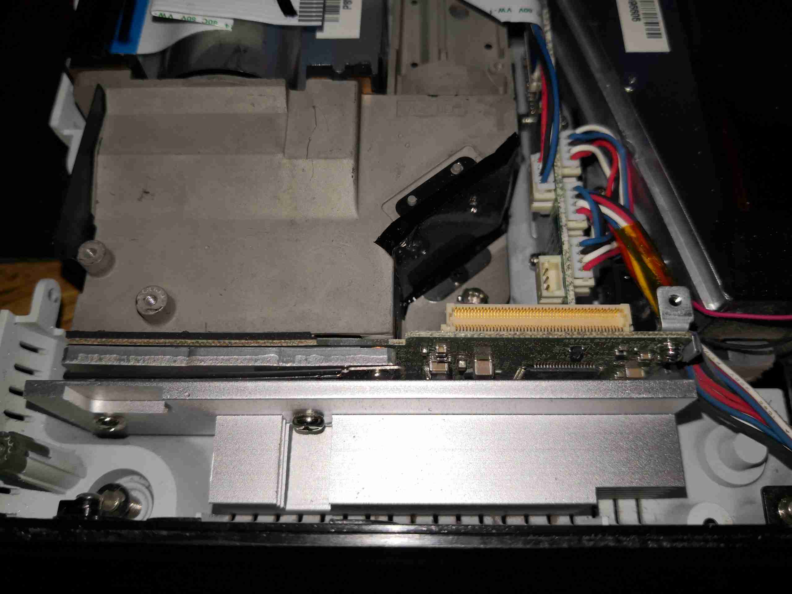
DLP Frame
At the back of the light engine is the DLP module, with it’s substantial heatsink.
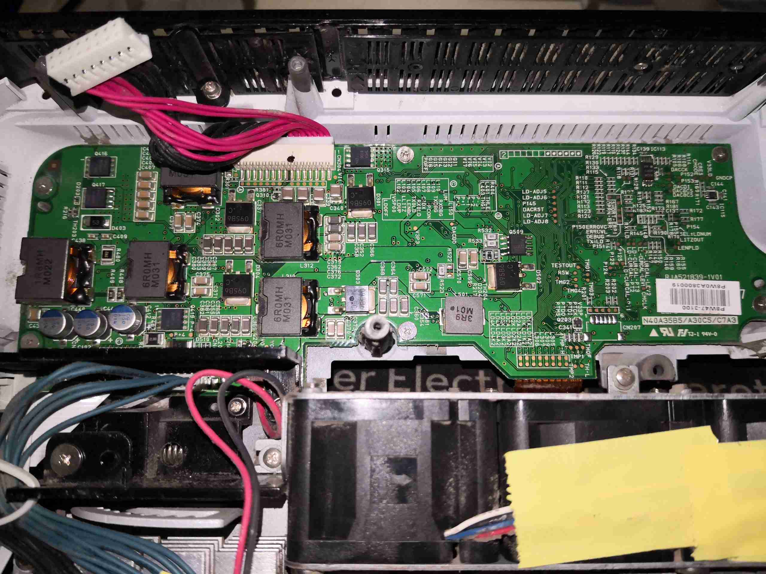
Light Source PSU Board
Hiding under the mains PSU, is the light source control PCB. This contains several DC-DC converters, which run the 4 strings of laser diodes, the large Phlatlight Red LED & it’s associated TEC cooler. This board takes the incoming +12v from the mains PSU through the multi-way loom at top centre. There are multiple cores on this connector to spread the load – at normal brightness, in Eco mode, I measured the power consumption at about 8.5A at 12v input for the entire projector.
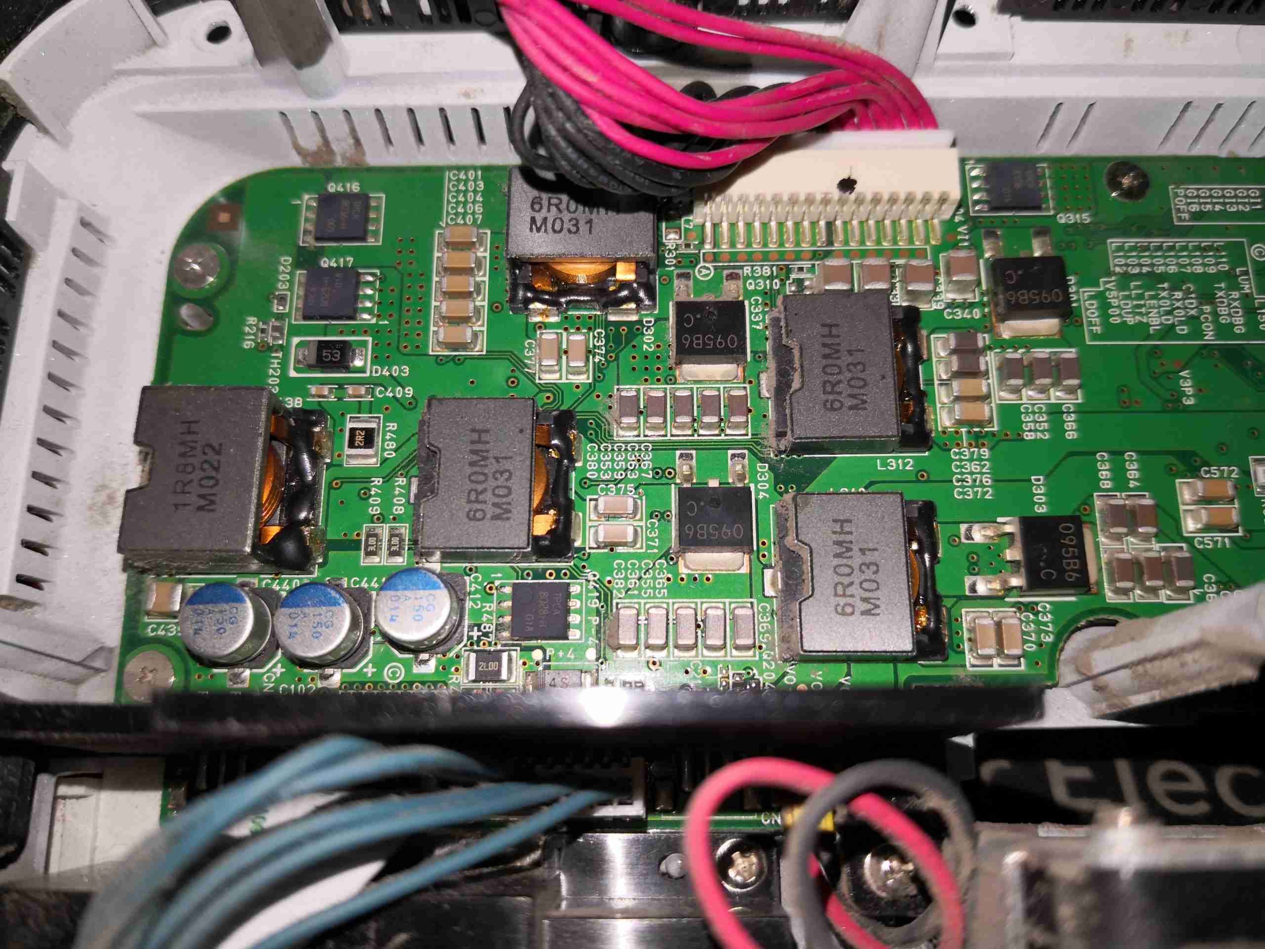
DC-DC Converters
The left side of the board is dedicated to the high power section of the controller. There’s a power inductor for every channel.
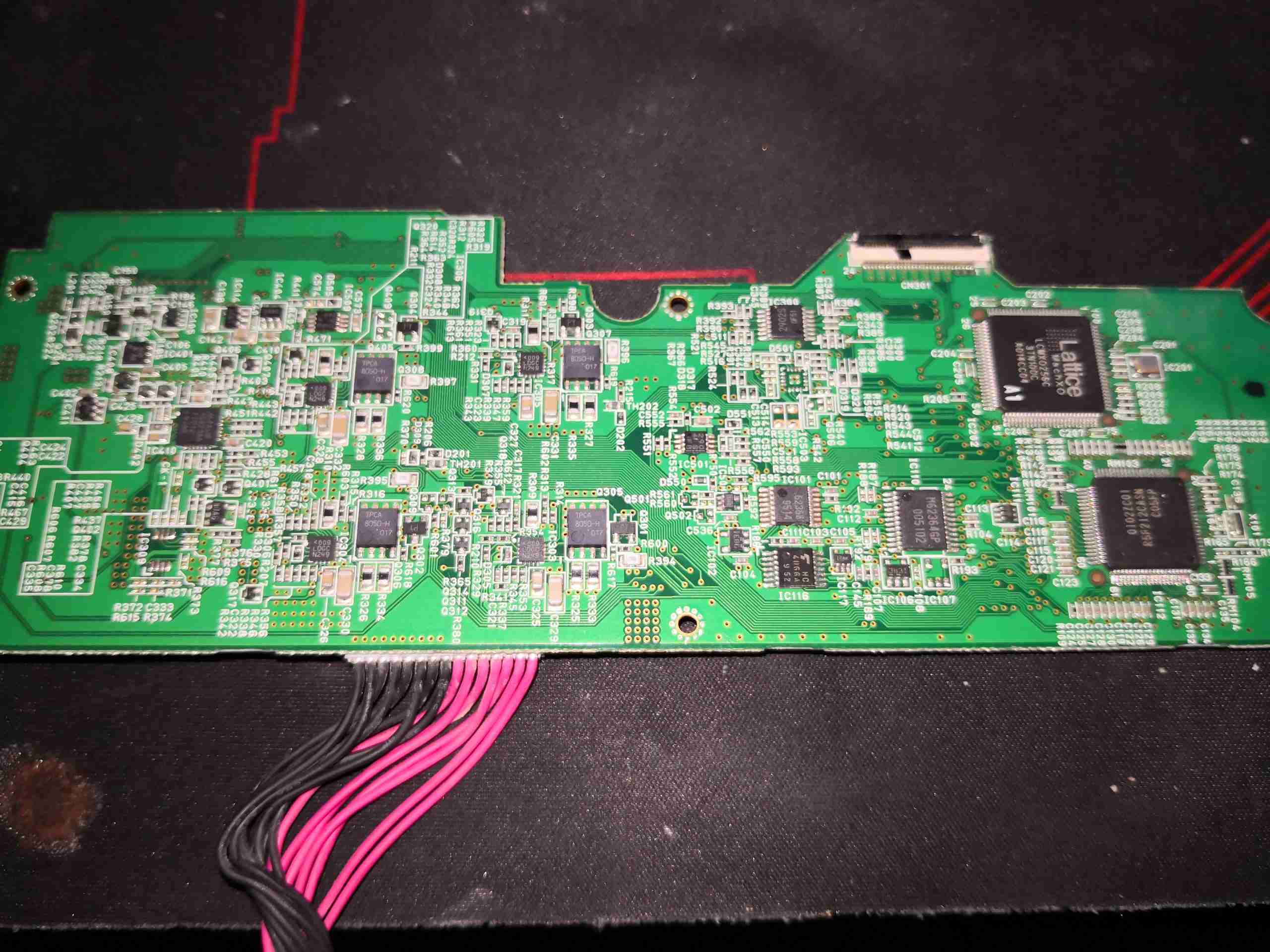
Light Source Drive Board
The other side of the board is very heavily populated with components.
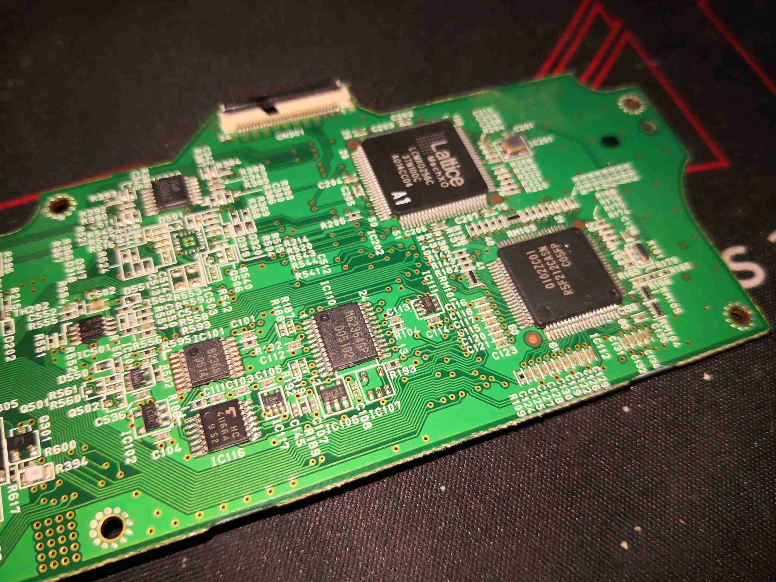
Control Logic
The right hand side has the control logic, a Lattice CPLD, and another Renesas Microcontroller. There’s also some glue logic here & a dedicated DA converter.
Power Drivers
The other end of the board has the power drive control logic. There’s a MAX16821AA LED buck driver for the Red LED, and 4 drive ICs for the laser diodes, which are marked <009 LDGC N249. I haven’t been able to find anything about these, so they may be custom.
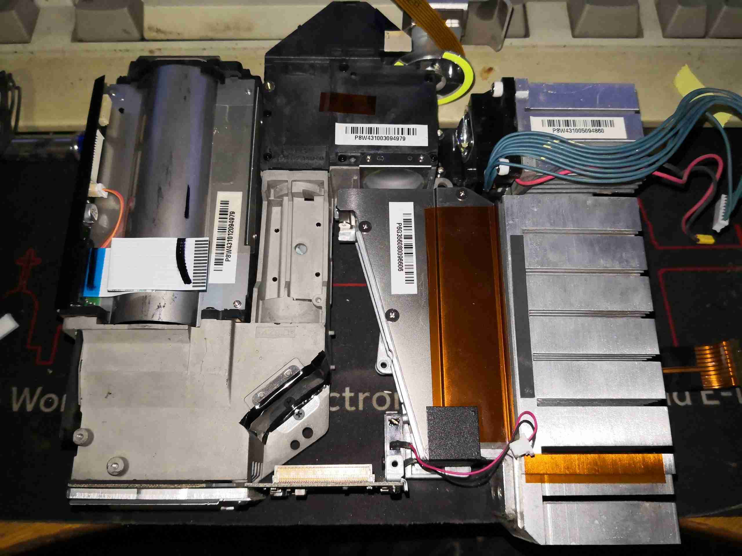
DLP Light Engine
Removing some screws allows the entire optical assembly to be removed from the lower shell. This may be mostly manufactured from a magnesium alloy from the rather low weight.
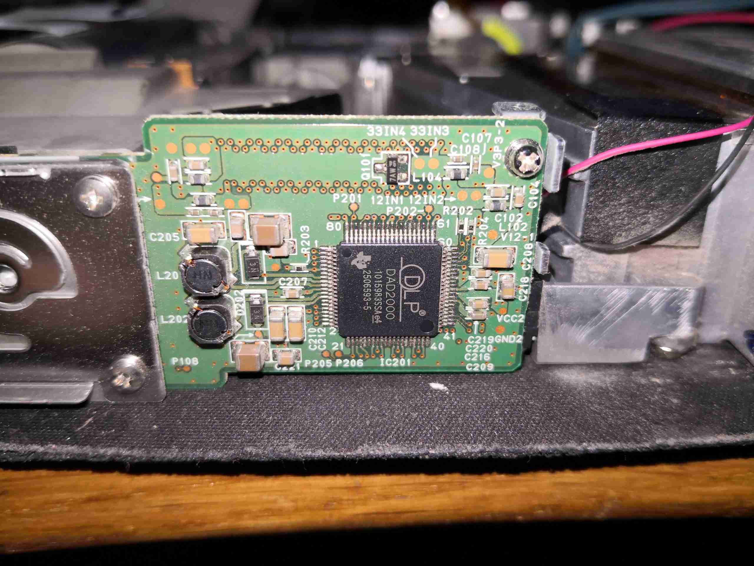
DLP Board
On the back of the DLP module is the DLPA200 Micromirror Driver IC. This generates the high voltage bias supplies for the DMD chip (+/-28v) from the 12v rail, generates all the timing waveforms required for the DLP chip. There’s a couple of power inductors for the onboard regulators. Video data is sent from the main image processing chipset to the DMD chip via 2 channels of LVDS.
DLP Mount
Now the heatsink has been removed, the rear of the DLP chip can be seen, with the remains of the thermal pad. The mount for the heatsink is sprung, to accommodate thermal expansion.
Red PhlatLight
The Red light required to create a colour image is generated by a giant LED, more on this one later.
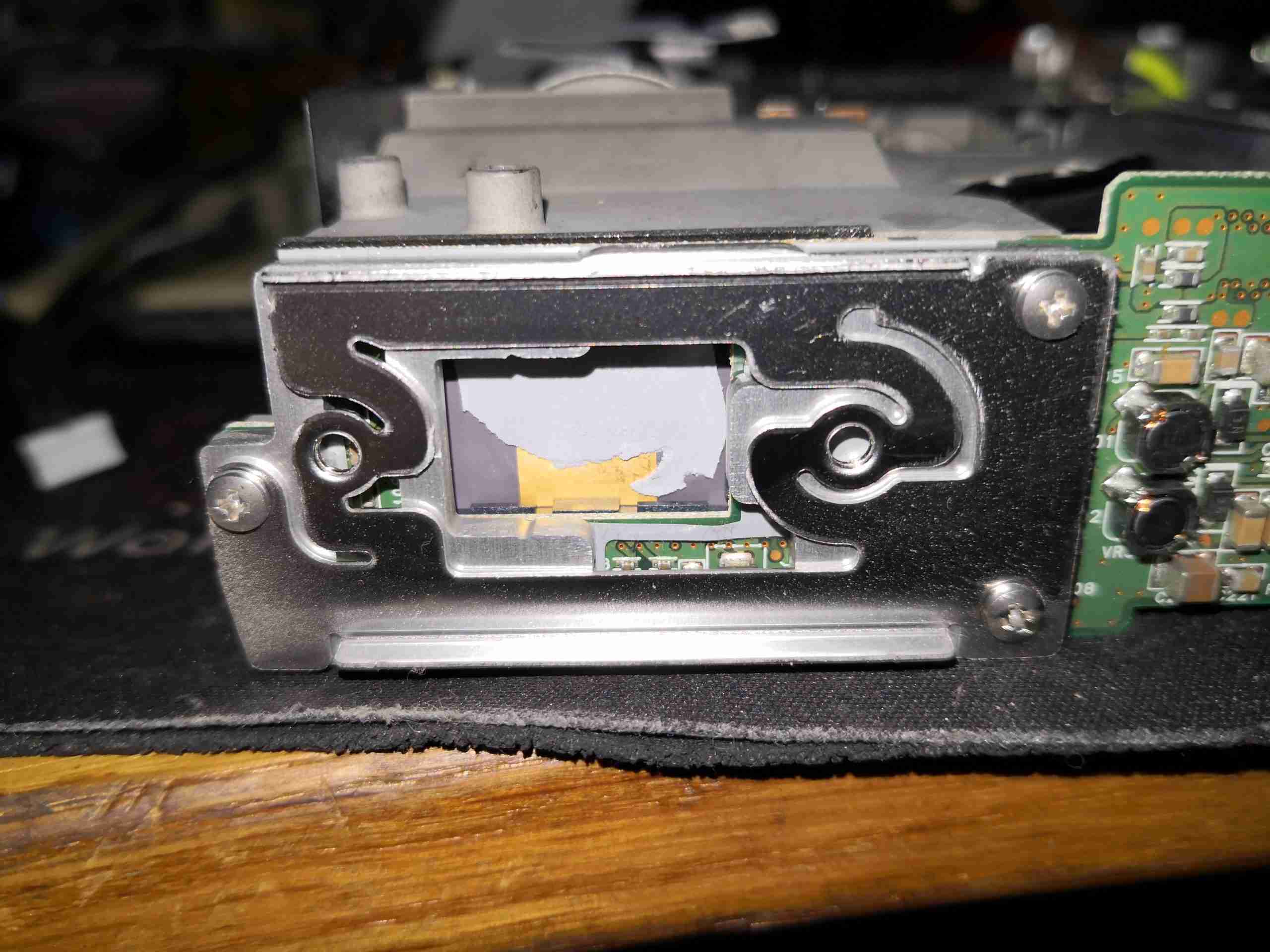
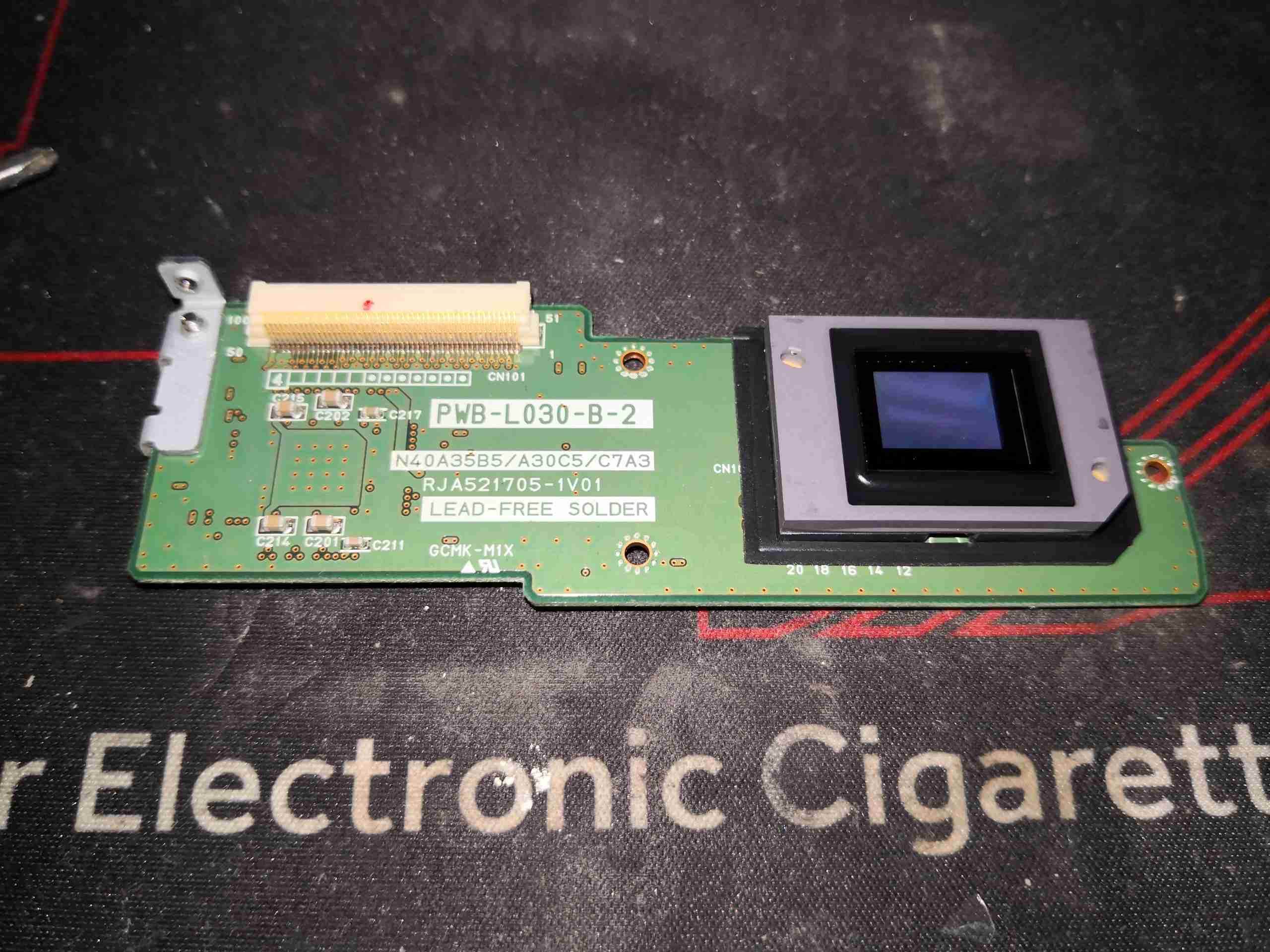
DLP Removed
Here’s the DLP board removed from the projector with the micromirror surface visible. This DLP has many dead pixels, hence the decommission at ~4500 hours of operation.
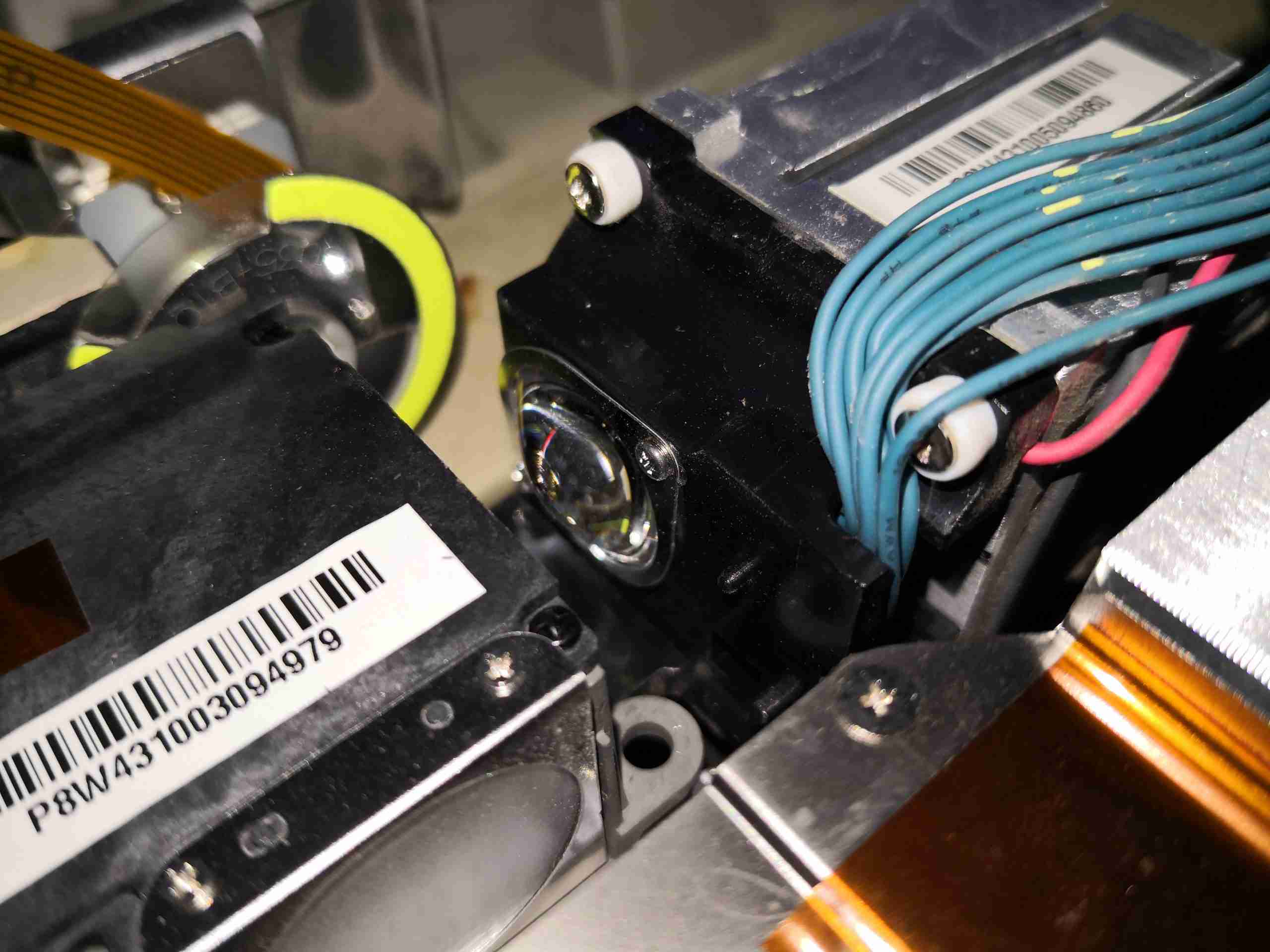
Laser Beam Combiner
The 24 laser diodes have their beams combined by this knife-edge mirror assembly, turning the beam through 90° to the lens on the left, which focuses the 24 beams down to the optics engine.
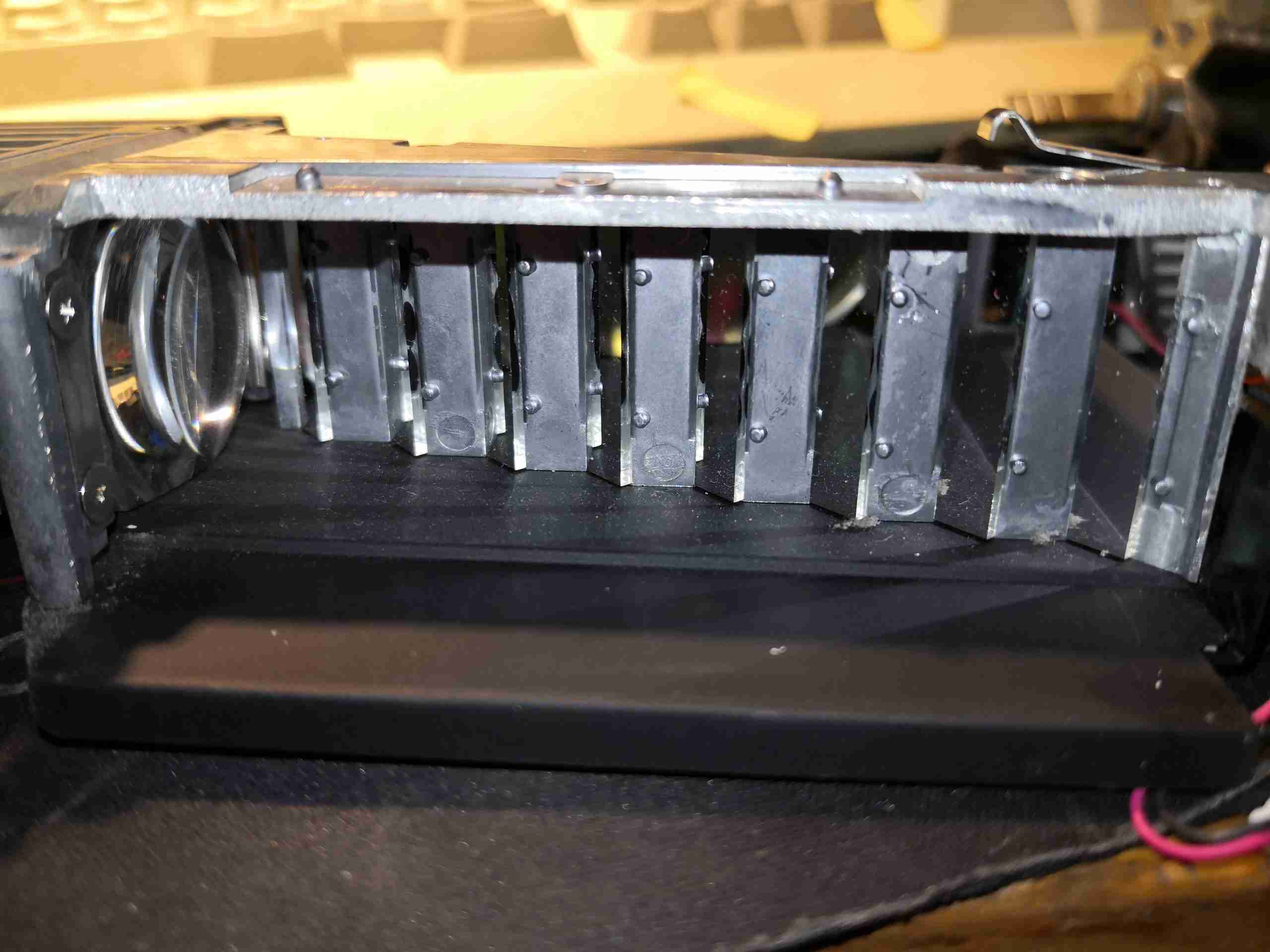
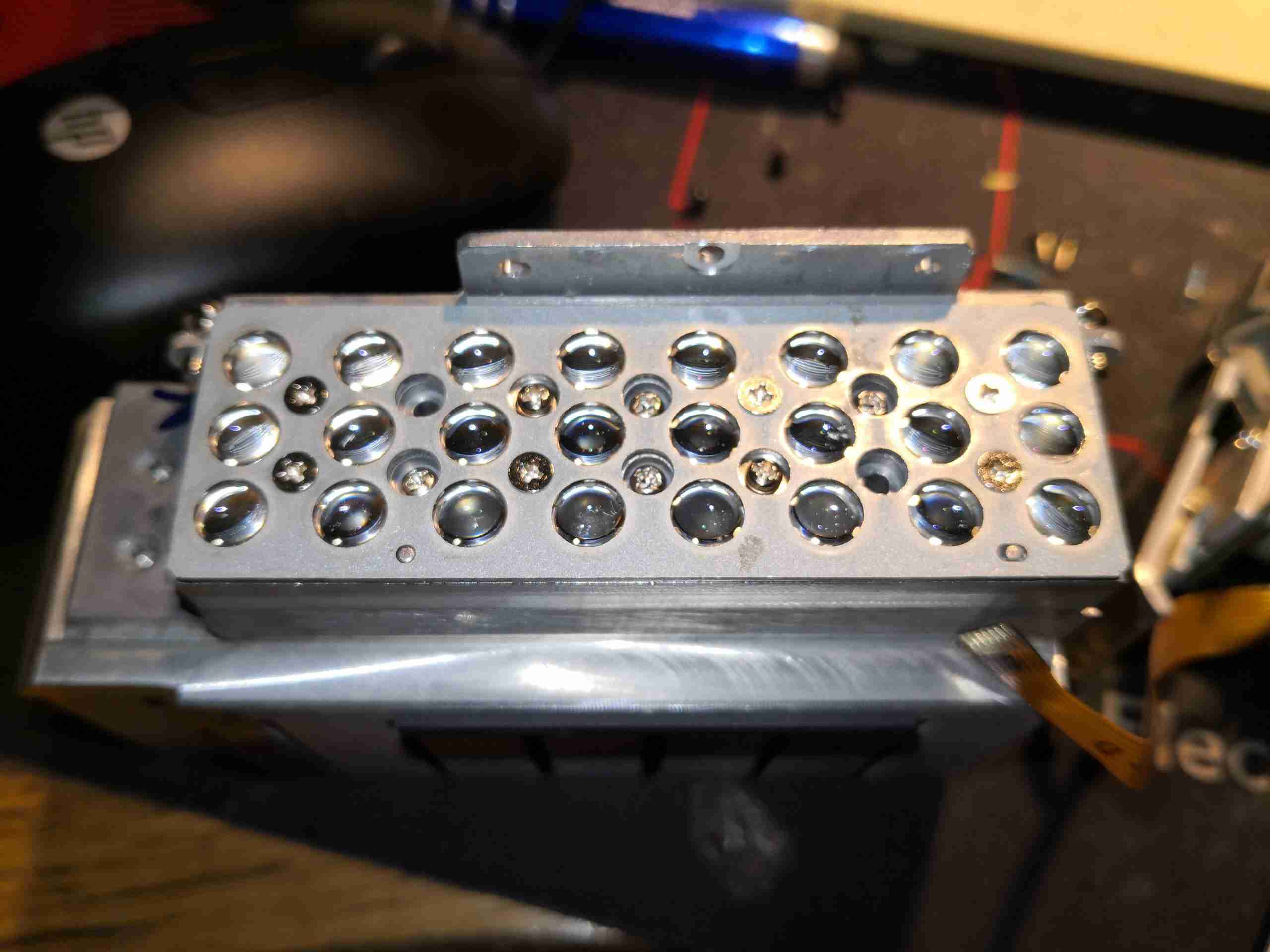
445nm Laser Array
Removing the beam combiner from the array allows the 24 diodes to be seen, mounted under their collimating lenses. This is one beast of a laser unit!
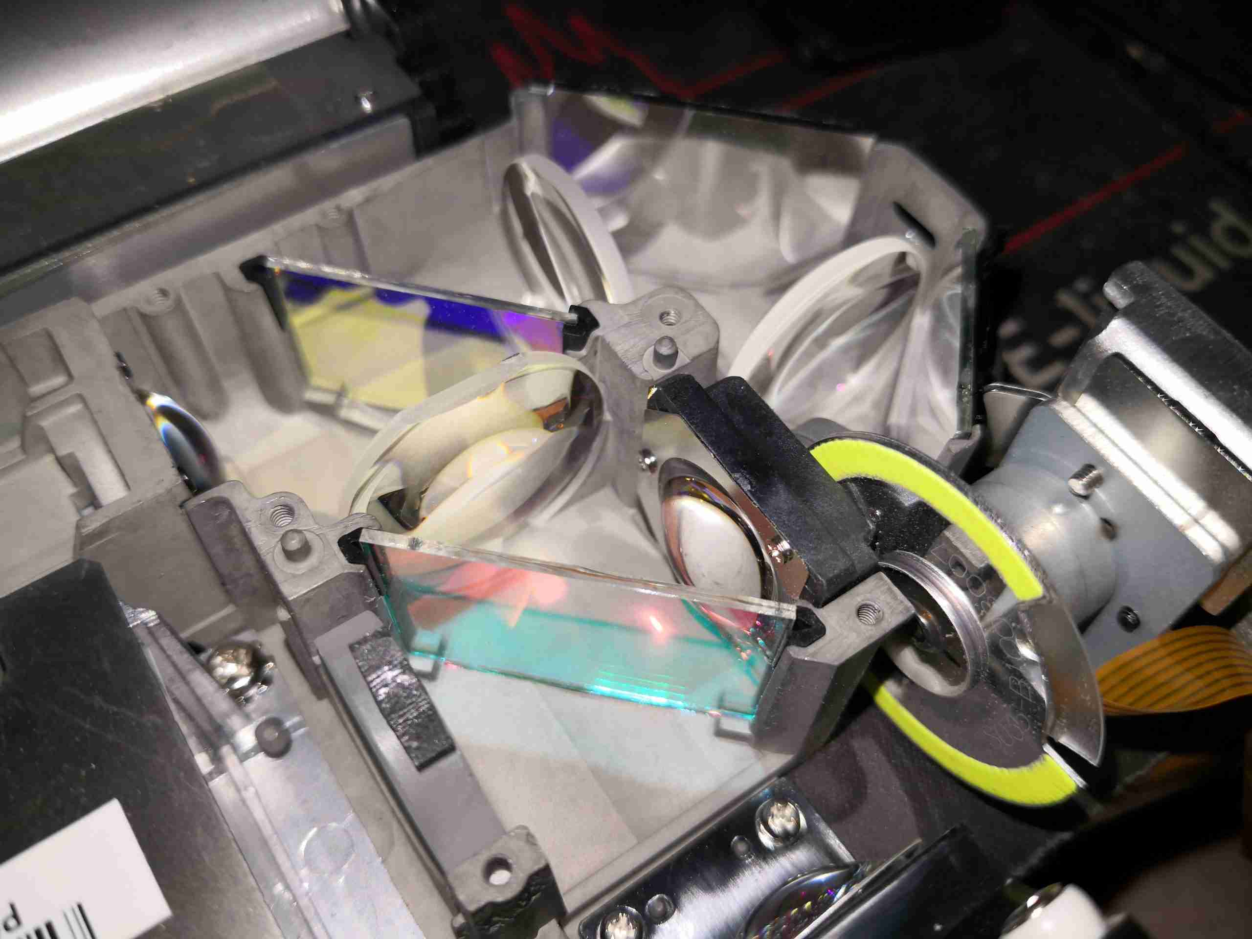
Dichroic Optics
Taking the cover off the optics assembly allows the main optical path to be seen. The blue laser comes in a bottom left, through the lens, the red LED comes in bottom right. The pair of dichroic mirrors manage the light path for the red & green light, while passing the blue straight through.
Optical Path
Here’s another view of the optical path, with both light sources visible.
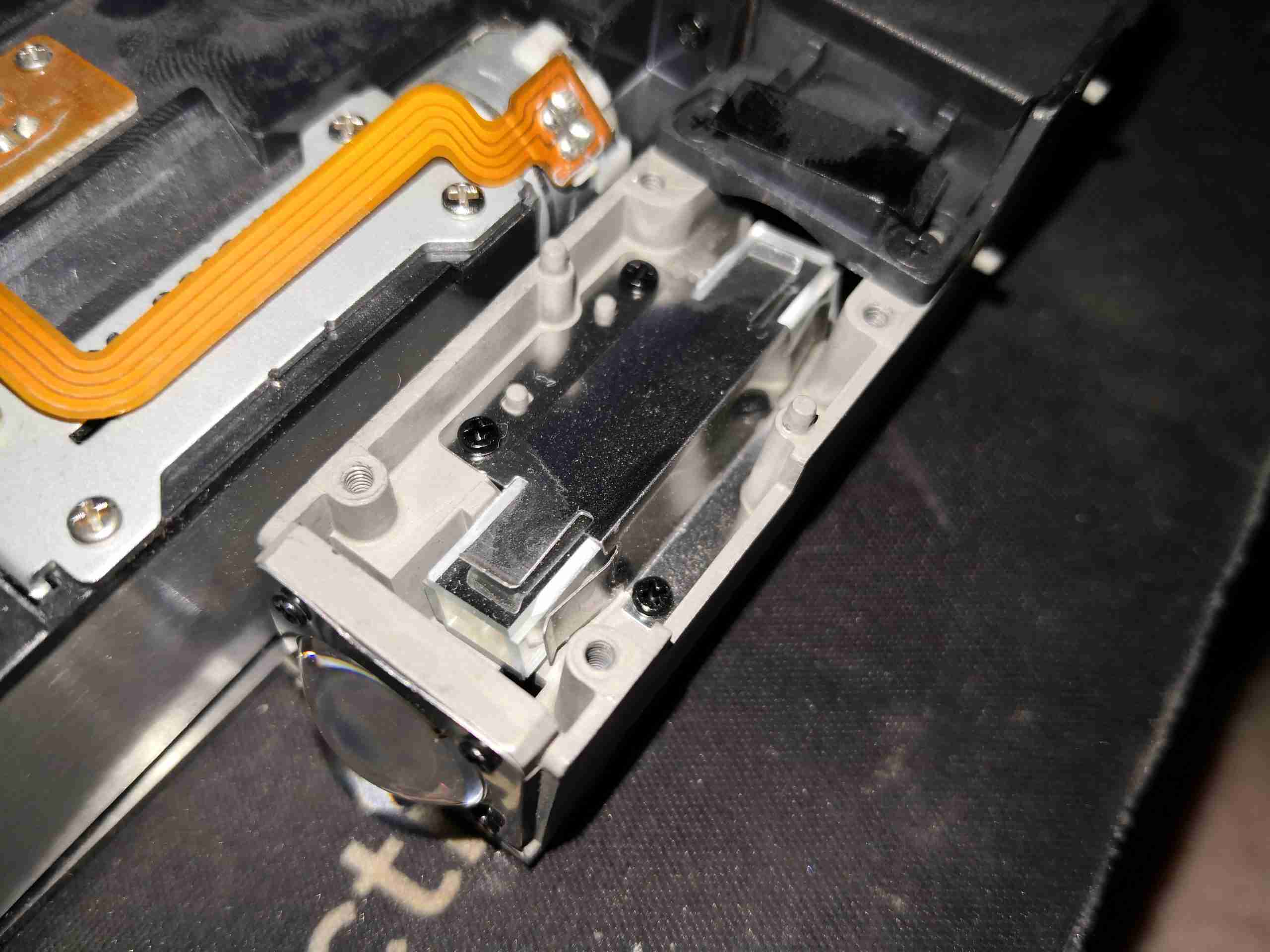
Light Homogenizer
After the light source, is the homogeniser – this tunnel of 4 mirrors facing each other evens out the light beam & removes all coherence from the laser light. This is important to not have any speckle in the image.
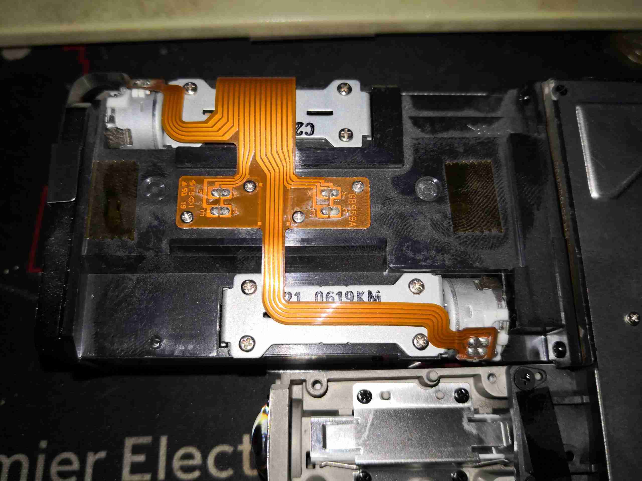
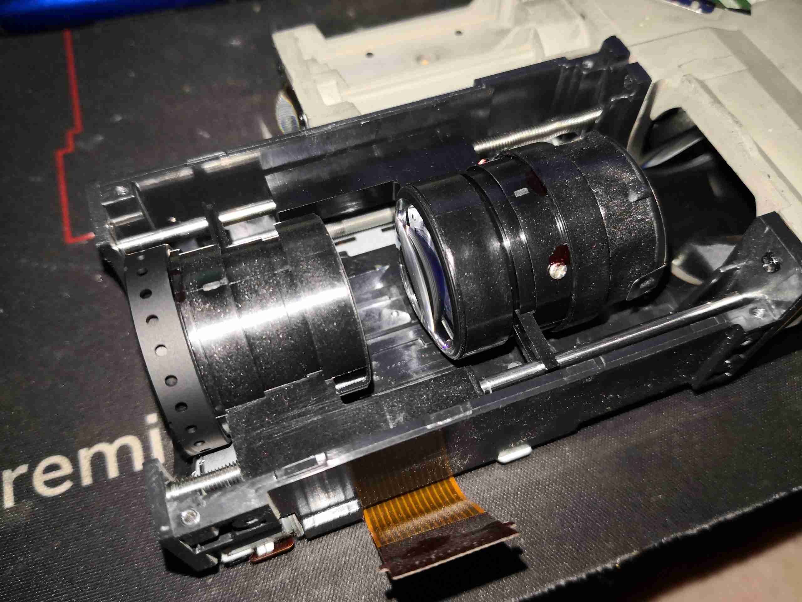
Focus & Zoom Motors
Underneath the objective lens are the pair of stepper motors that drive the focus & zoom mechanisms, along with their position sensors.
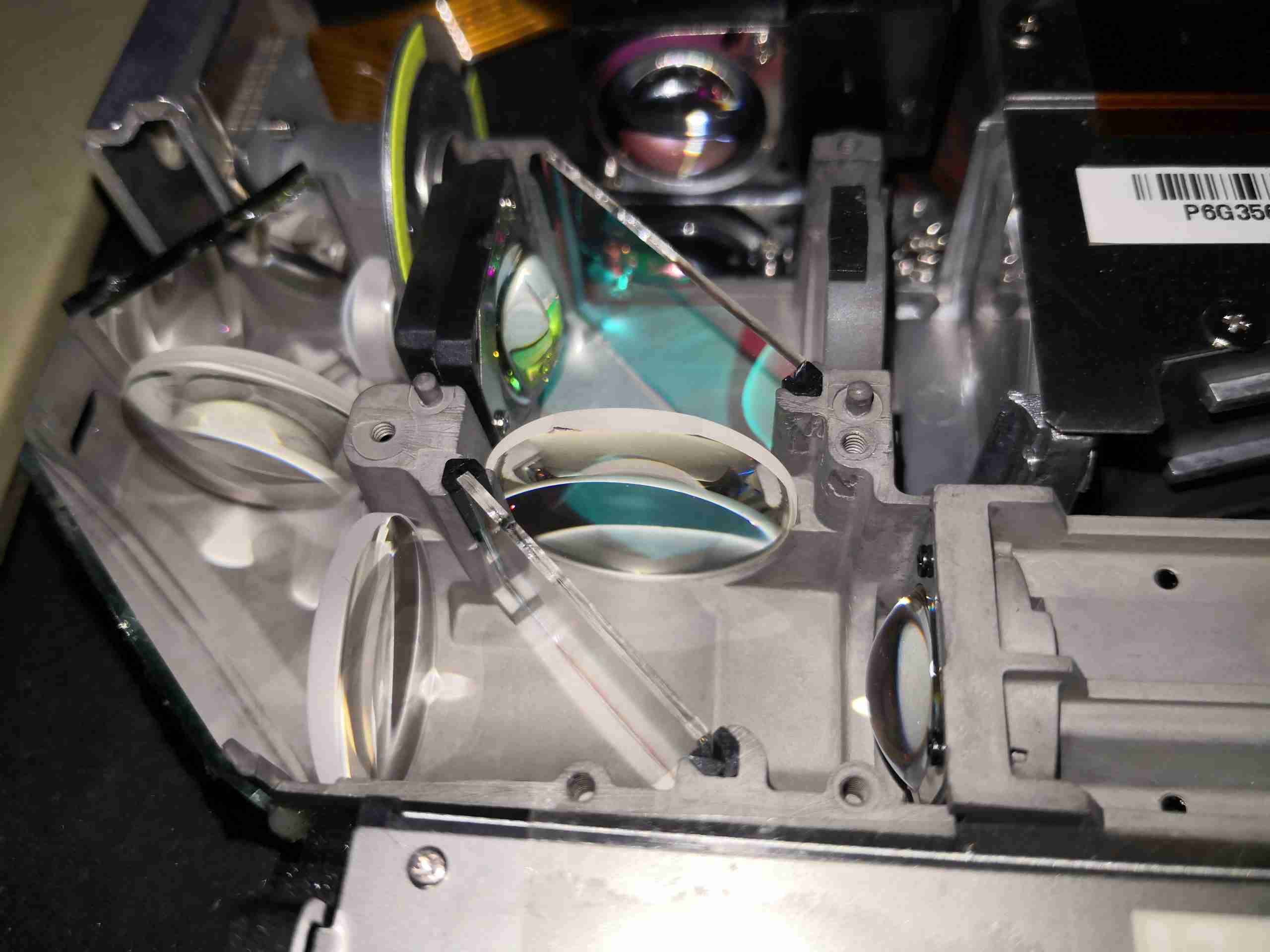
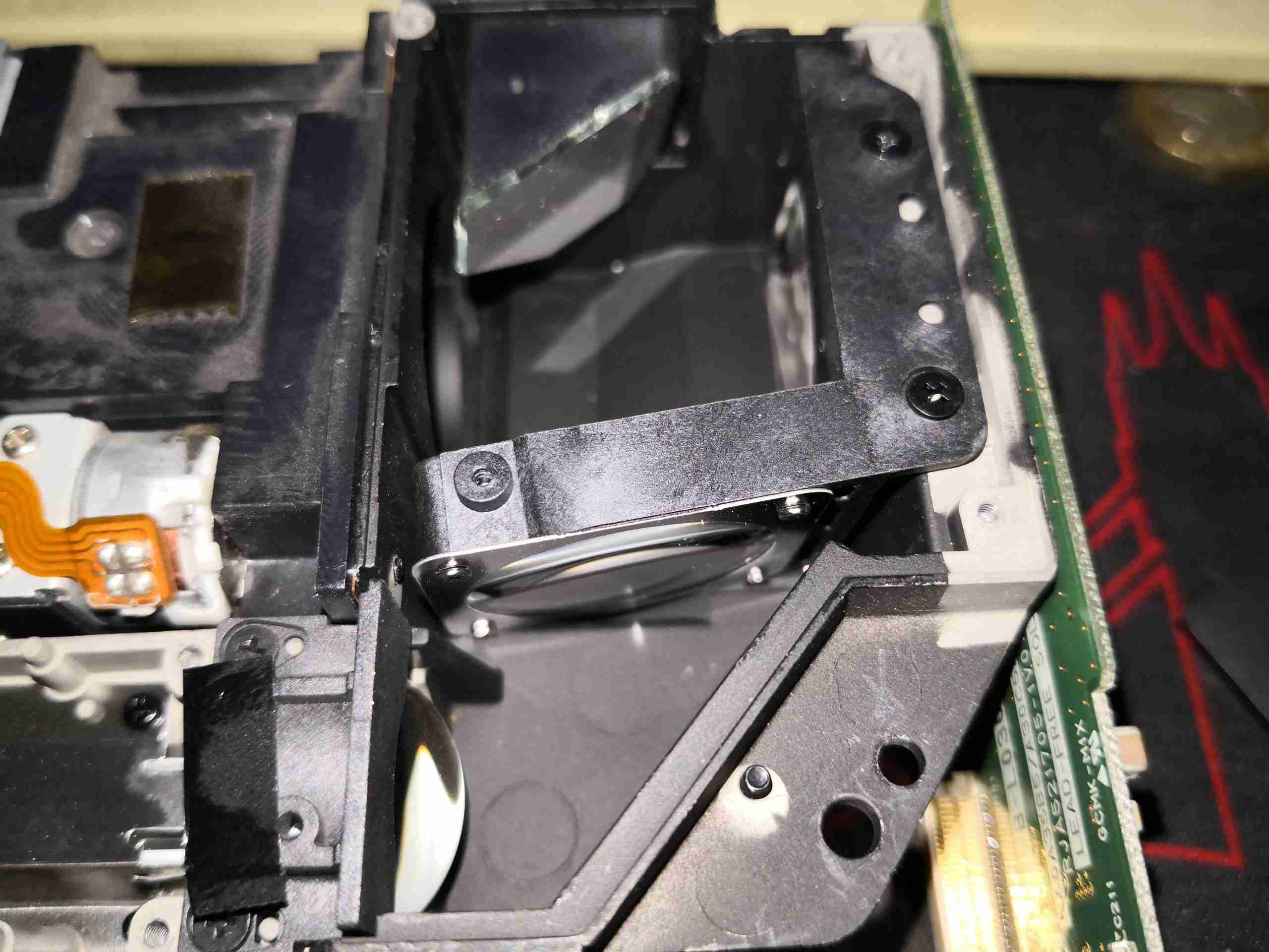
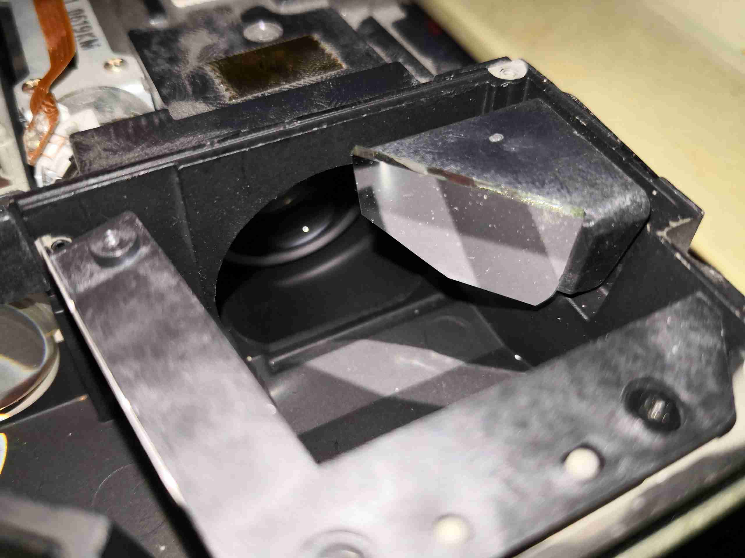
Turning Mirror
Just after the homogeniser, is the final optical path to the DLP. Here the light comes in a bottom left, and hits the turning mirror, after which it is focused onto the DLP chip by the mirror top centre. The objective lens is through the hole in the centre of the optical block, while the DLP is on the right side.
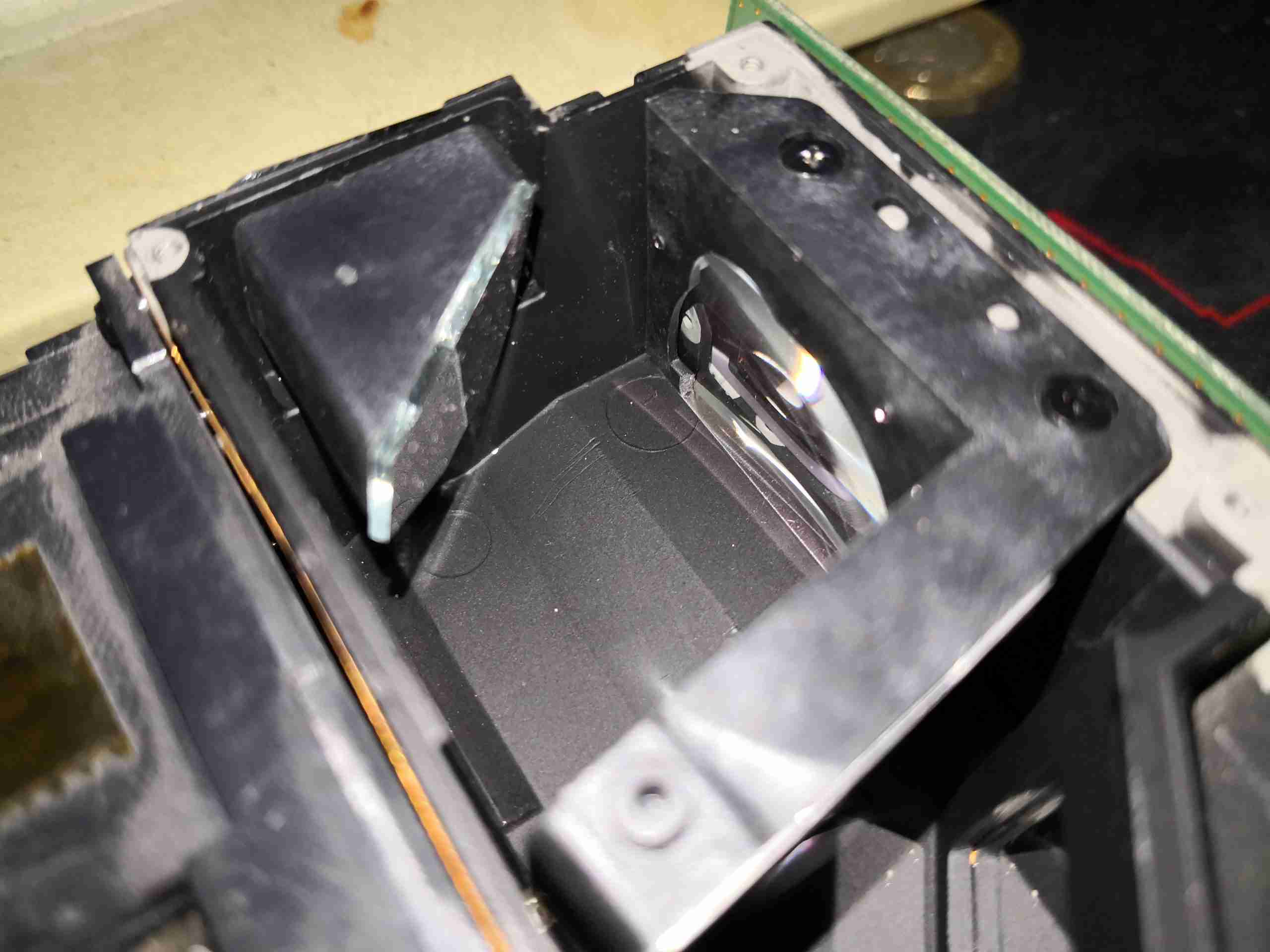
DLP Final Optics
Here’s where the DLP will be mounted in normal operation, with it’s lens in place.
Objective Lens
Finally, the created image is passed out through the objective lens to the projection screen.
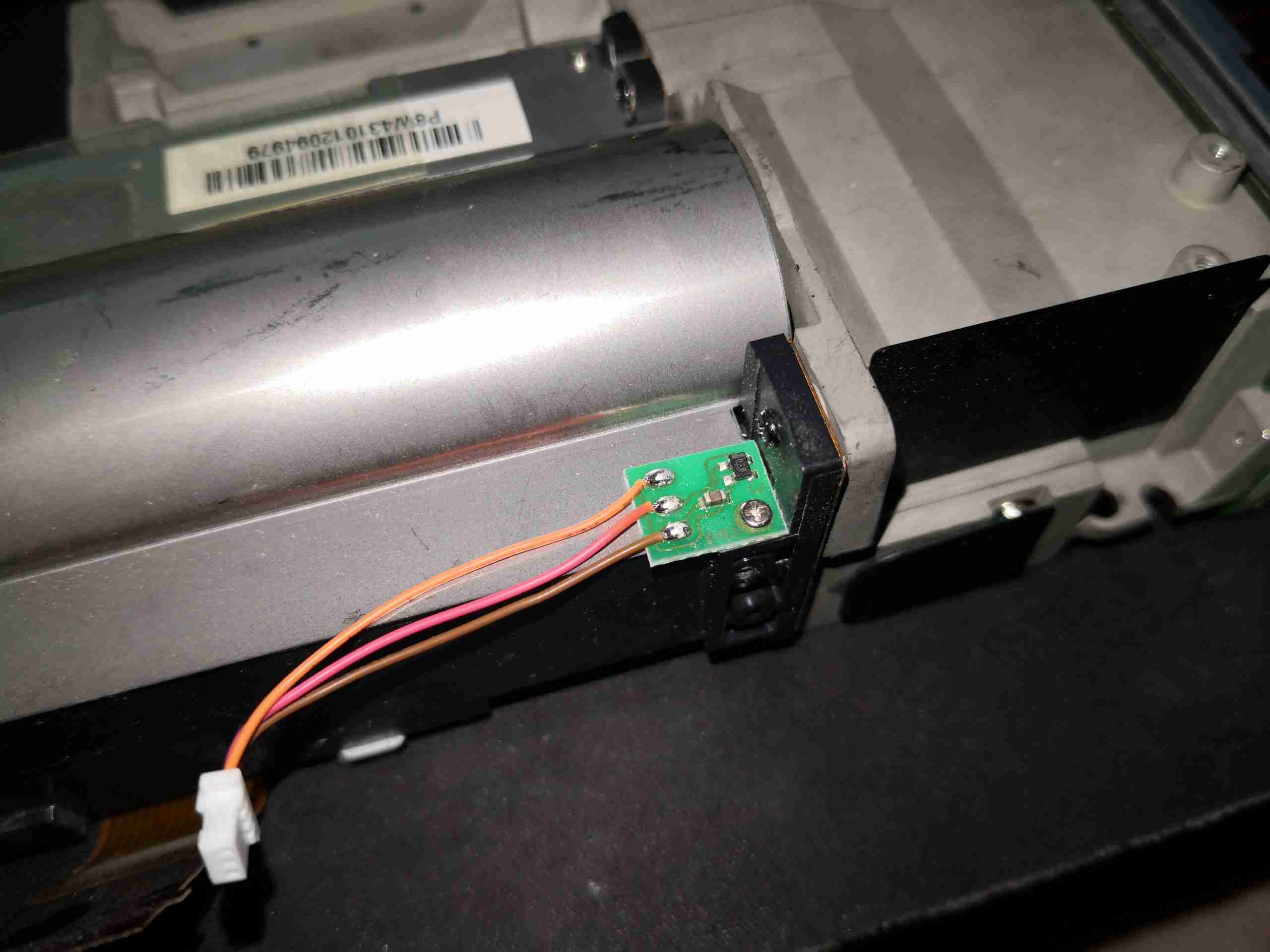
Hall Effect Sensor
There’s a sensor mounted on the side of the lens barrel, that I think is a Hall effect device, but I’m unsure what this would be used for, as there is no magnet anywhere near this to sense. It could also be a temperature sensor though, for the DLP & lens assembly.
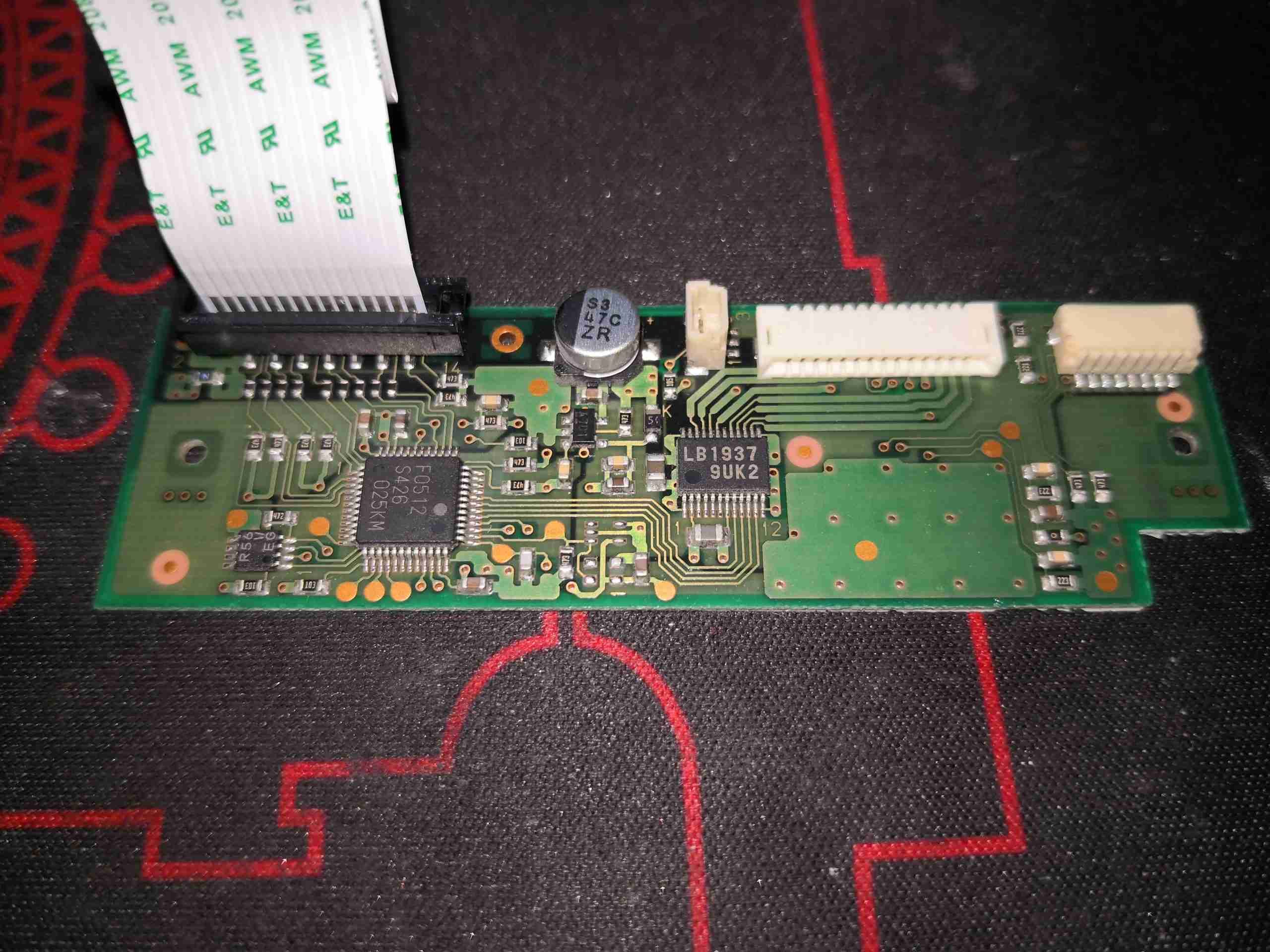
Stepper Motor Drive
The small PCB on the side of the lens unit holds the stepper motor drive IC, an LB1937 from Sanyo. There is another IC here, which looks to be a microcontroller.
Lens Assembly
Removing the top cover allows the moving lens assemblies to be seen. These move independently of each other to implement focus & zoom, via lead screw drives on the stepper motors.
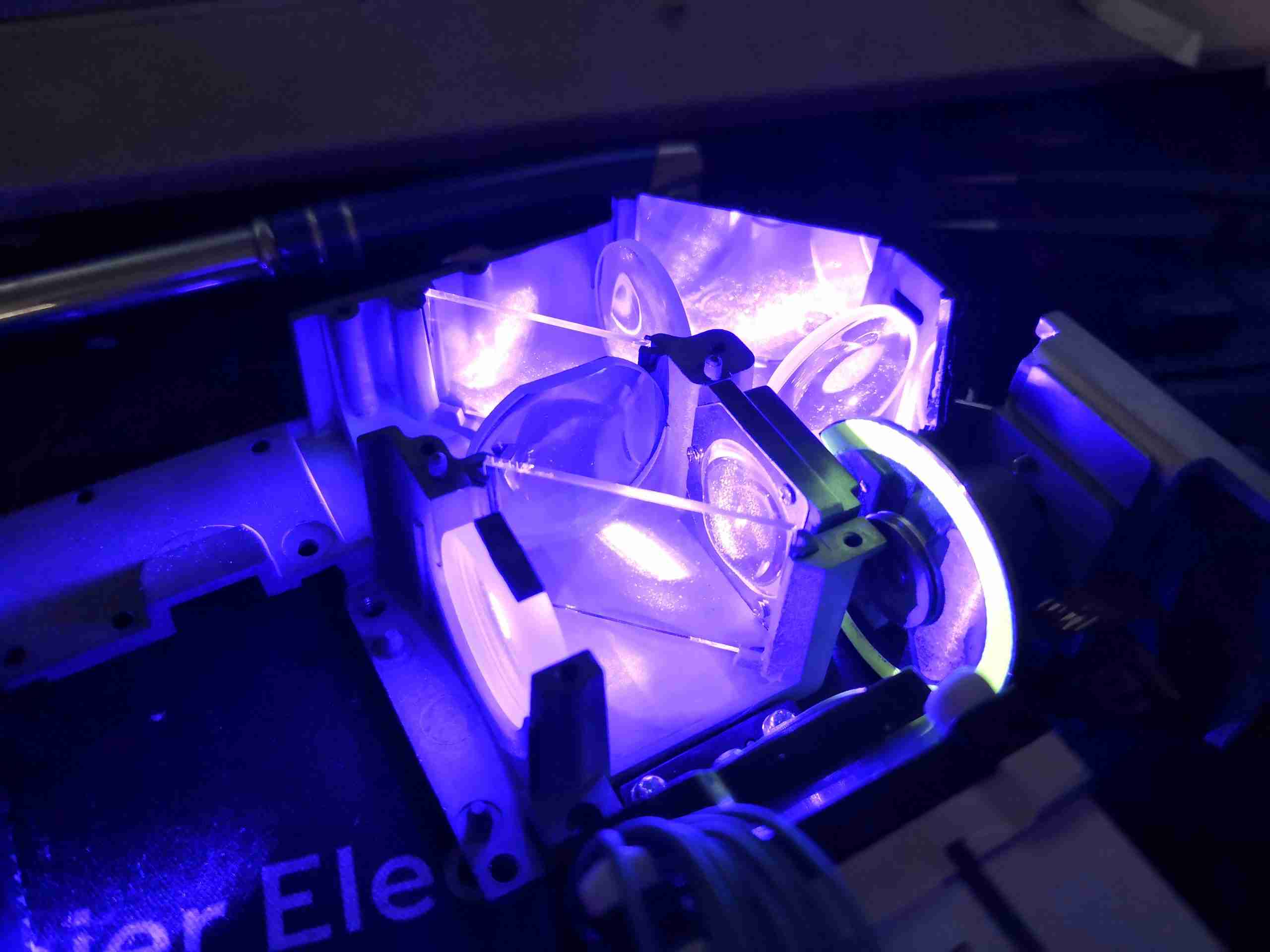
Blue Light Path
Here I’m shining a separate 445nm diode laser into the optical assembly, through the blue optical path. The phosphor wheel is turned to the clear section, which allows the 445nm light to pass straight through, being turned 180° by the mirrors & directed out towards where the DLP assembly would be.
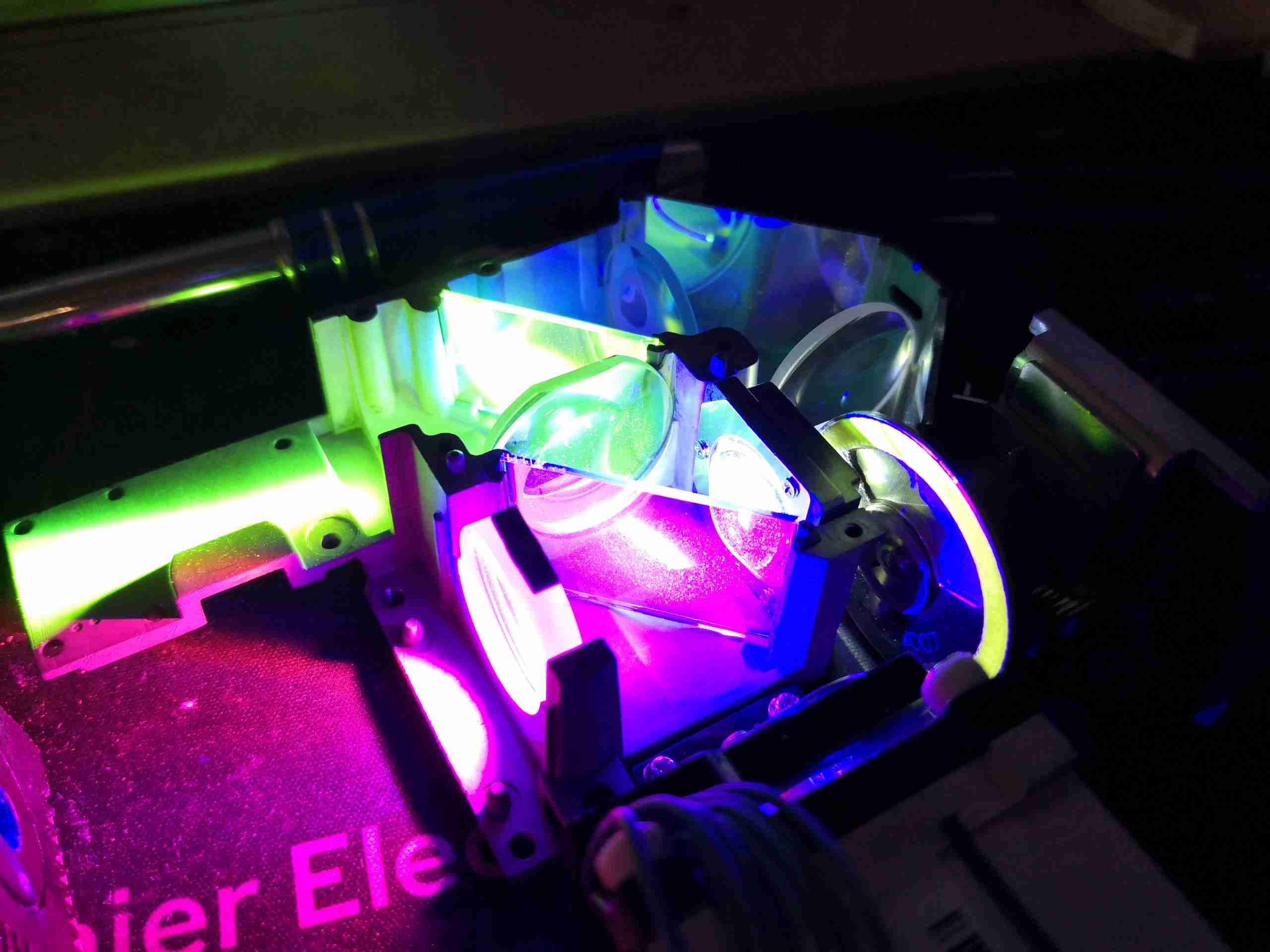
Green Light Path
Turning the phosphor into the light path causes a very bright green light to be generated, and passed back towards the 445nm laser entry point. The dichroic mirror in the way reflects this light to the left, through a lens & then to the other dichroic mirror to be turned another 90° to the DLP assembly. I’m not sure where the magenta light is coming from – the phosphor probably generates light on more wavelengths than just pur green, giving some red to mix with the blue.
PhlatLight LED
Here’s the Red LED removed from it’s cooling & collimation assembly – this has an enormous silicon emitter area, and apparently these LEDs are designed to be uniform in light emission, specially made for projection use. There’s a thermistor onboard for temperature sensing – sensible when the datasheet gives CW currents of 8A, and pulsed currents of 13.5A!
LED TEC Cooler
Not surprisingly, cooling this beast of an LED requires more than just a heatsink, so it’s mounted on a TEC module, possibly around 40W thermal capacity.
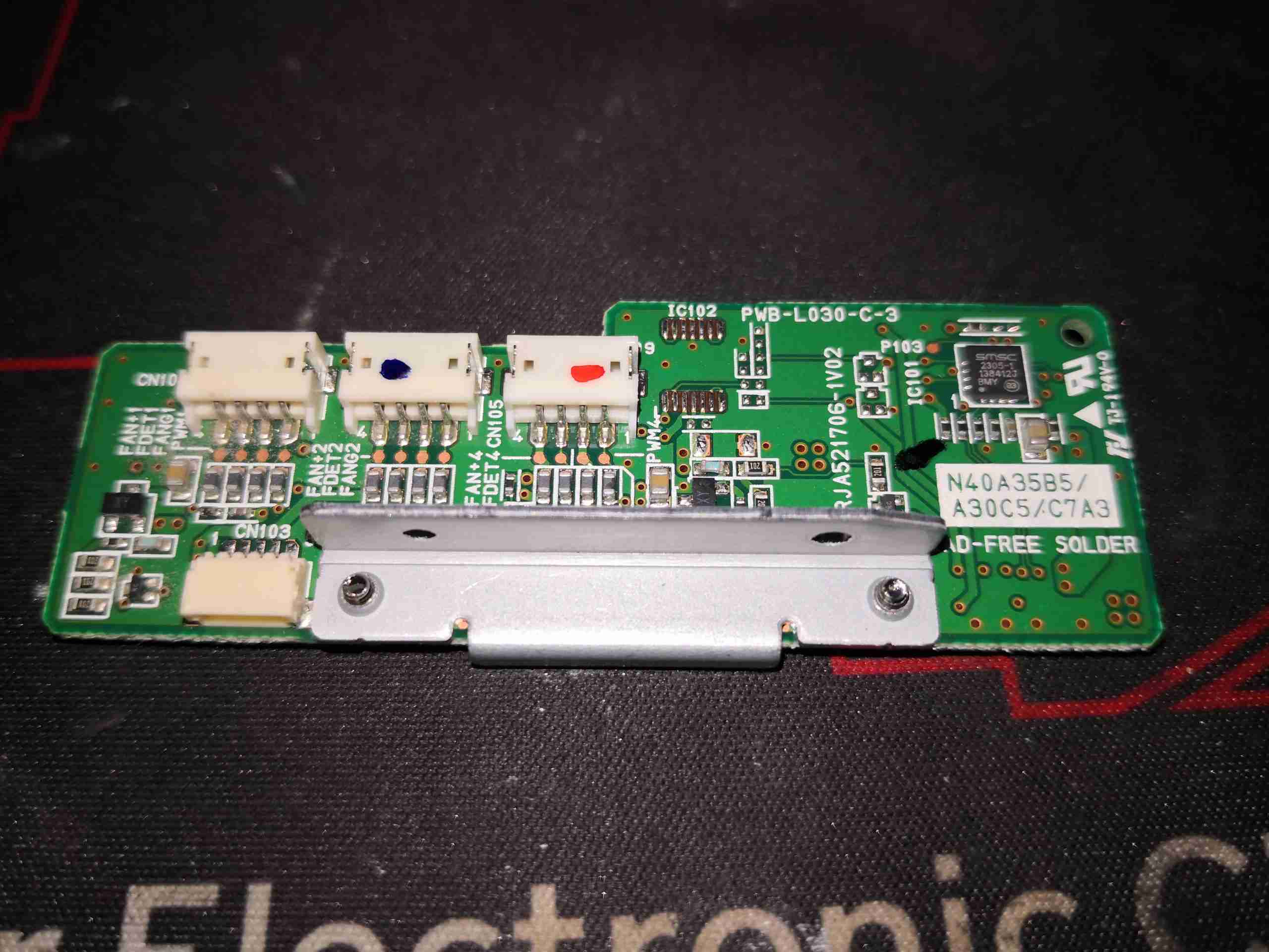
Fan Control Board
Fan control is handled by this little PCB, squeezed in between the optics engine & 445nm Laser array. There’s a SMSC EMC2305 I²C 5-channel PWM fan controller on here, communicating back to the main system microcontroller. Besides some passives, and 4 transistors to make sure the fans don’t start at full power when the projector is powered on, there’s not much else.
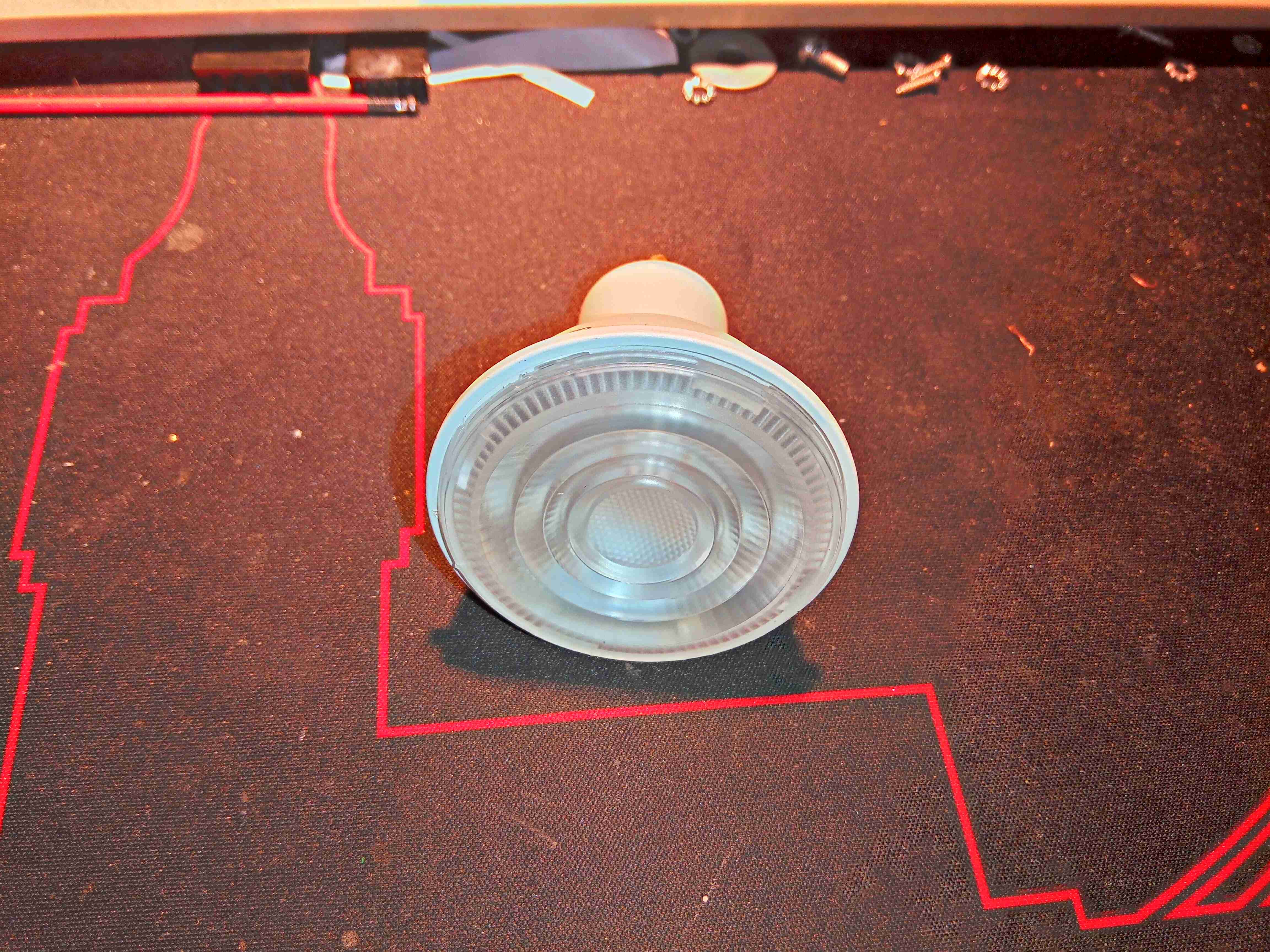
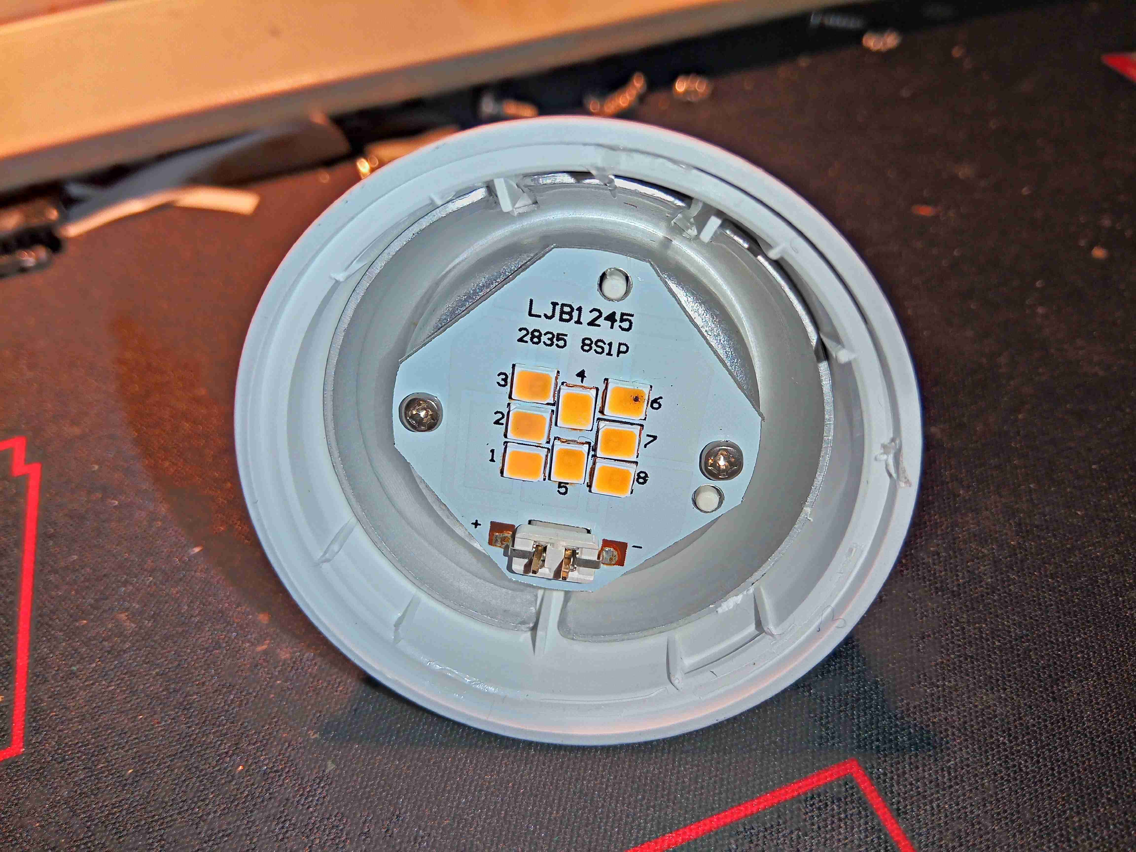
Here’s a recently failed 5W GU10 lamp, which is completely dead – not even a single LED still shining.
Markings
According to the markings, this lamp draws 50mA at 230v & outputs 345 lumens
Lens Removed
After popping the lens off the body, the failure mode is obvious. The top right LED has the Black Spot Of Death, where one of the LED dies has catastrophically failed in service. As these lamps usually have all the multi-die LEDs in series, a single failure will cause the lamp to totally fail. Running LEDs hard, with little cooling is a common cause of this kind of failure. There isn’t much in the way of heatsinking in this lamp, as the outer casing is plastic, and even though the LEDs are soldered to an aluminium cored PCB, the only other heatsink is the aluminium base for the PCB, which is in contact with the outer plastic.
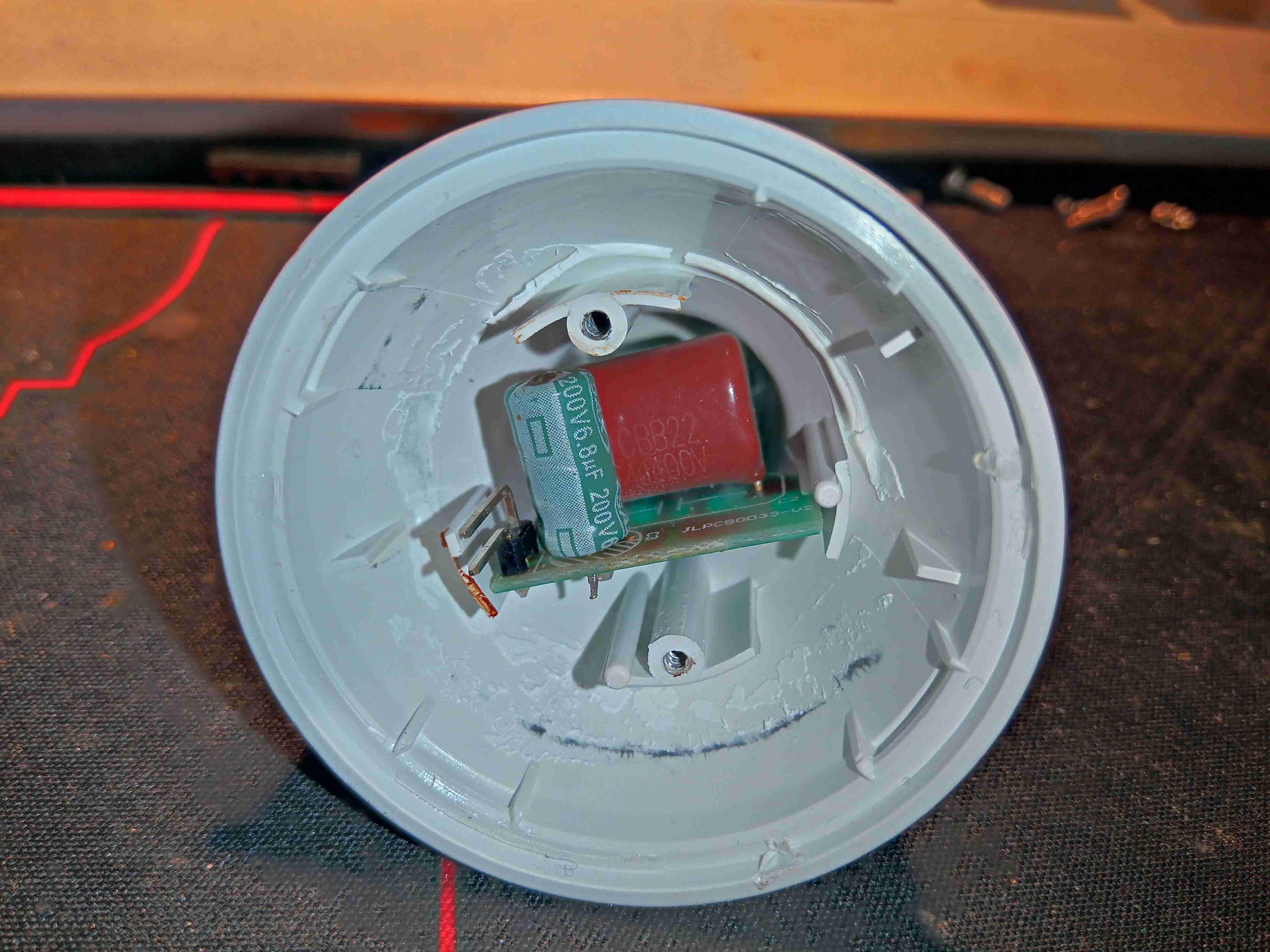
PSU
Removing the LED board & backing plate allows access to the power supply in the rear of the lamp. There’s no switching supply in this one, just a large film capacitor.
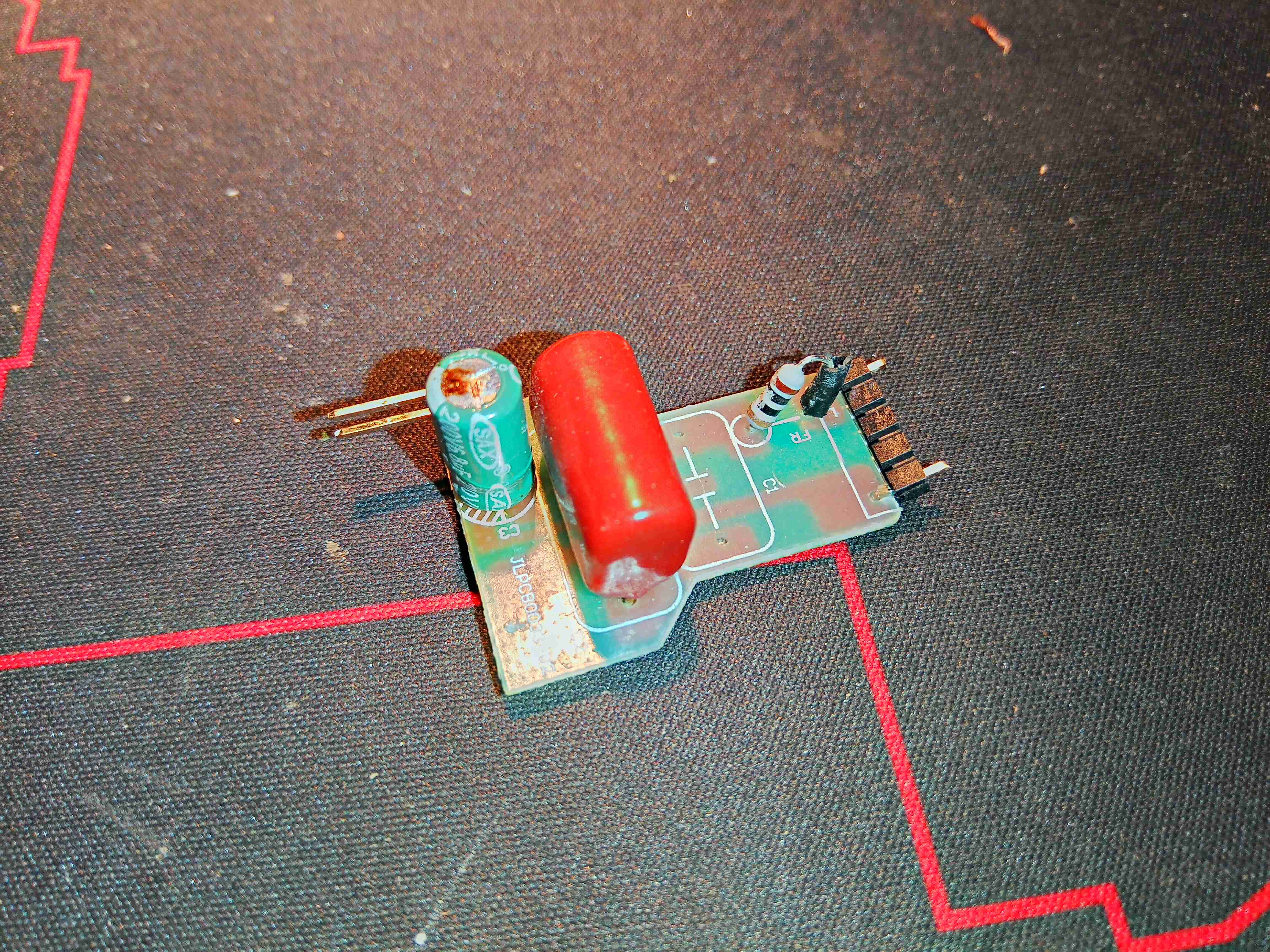
Capacitive Dropper
Snipping the pins off the back allows the PCB to be removed, exposing the capacitive dropper from the mains. The output electrolytic cap has also failed on this board, as can be seen from the opened vent on the top.
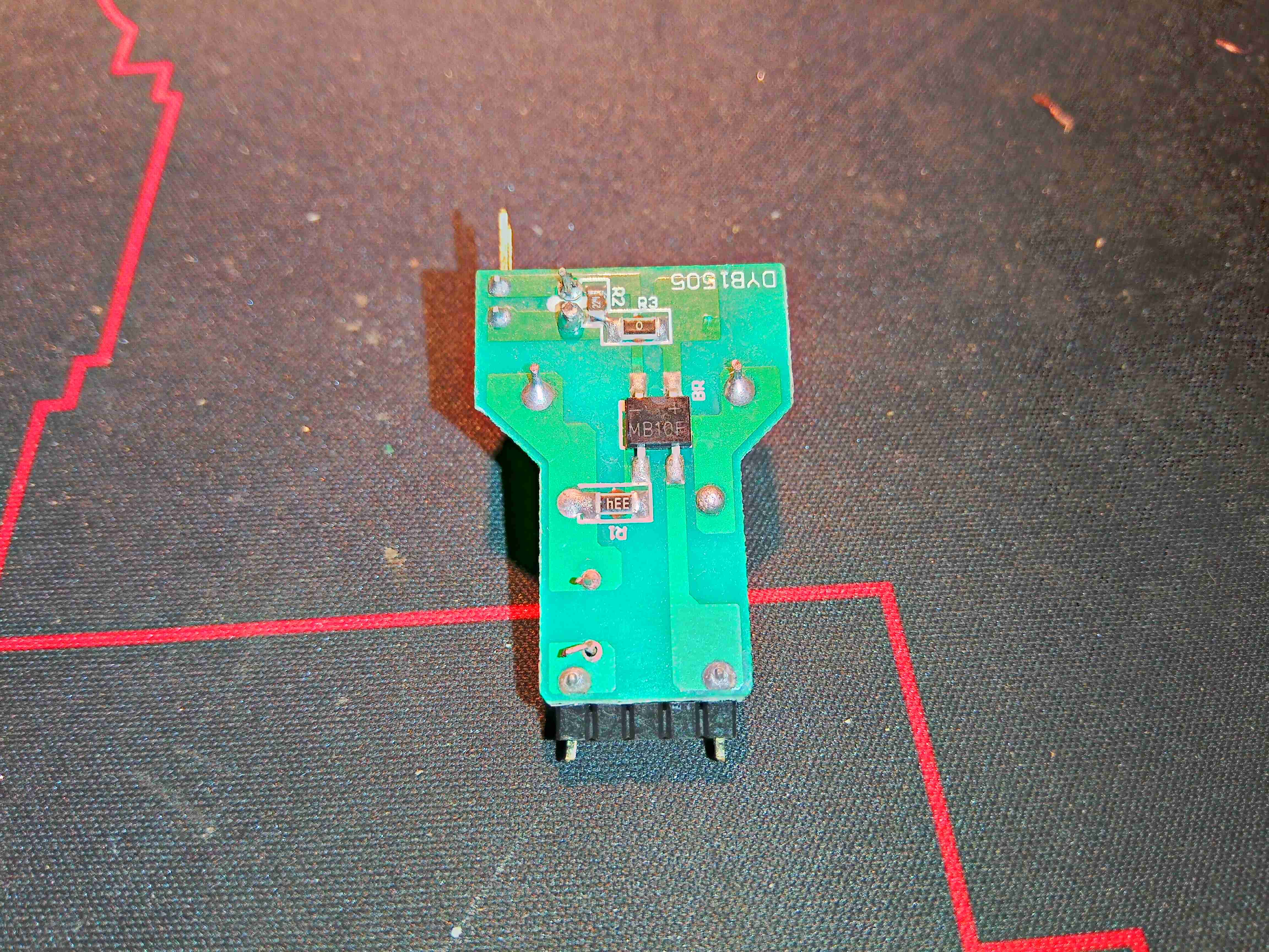
PCB Reverse
There isn’t much on the back side of the board, apart from the bridge rectifier & a couple of resistors.
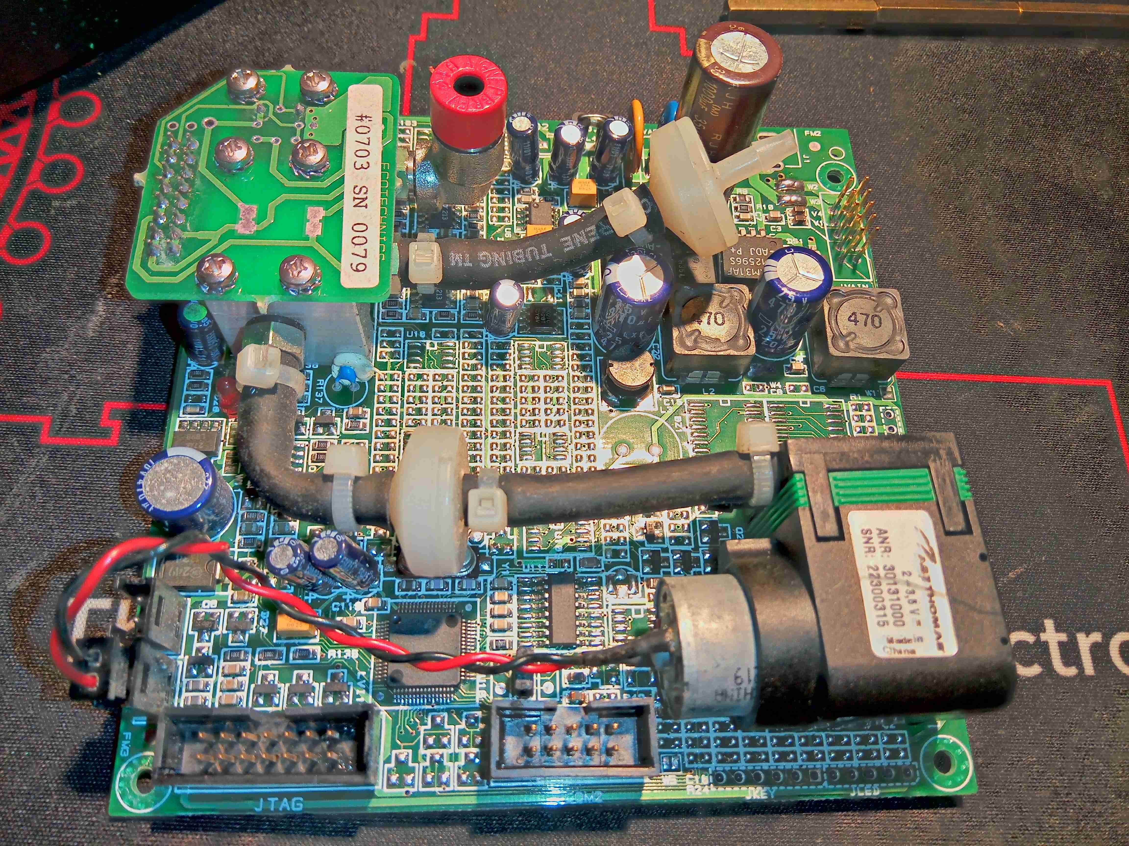
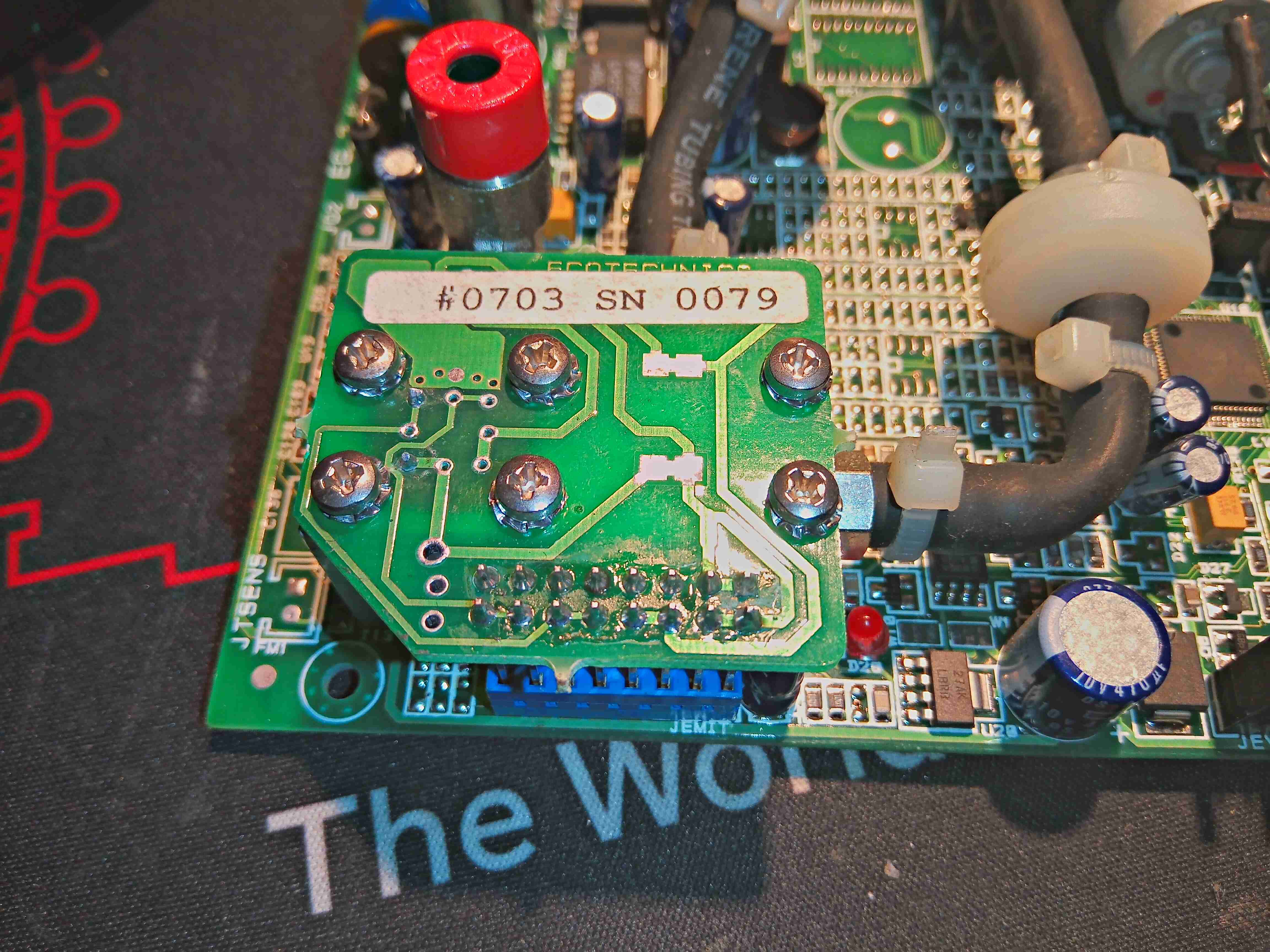
This unit recently appeared on eBay, as a spare part from a refrigerant charging machine, and I figured it would make a good explorational post. This unit analyses the purity of R-134a refrigerant gas, using an Infrared sensor cell, and communicates over RS-232.
The sensor cell itself is at the top right of the board, we’ll get to that later on. There’s a small diaphragm pump at the lower right, for purging the cell with air. The port with the red cap is the outlet, and the remaining open hose barb is the input of gas to be tested. This would connect to a flow regulator & solenoid valve that the board controls.
It’s pretty clear that this board has multiple applications from all the unpopulated components. There’s space for a keypad, indicator LEDs & an LCD on board, so maybe this can also be fitted to a handheld analyser?
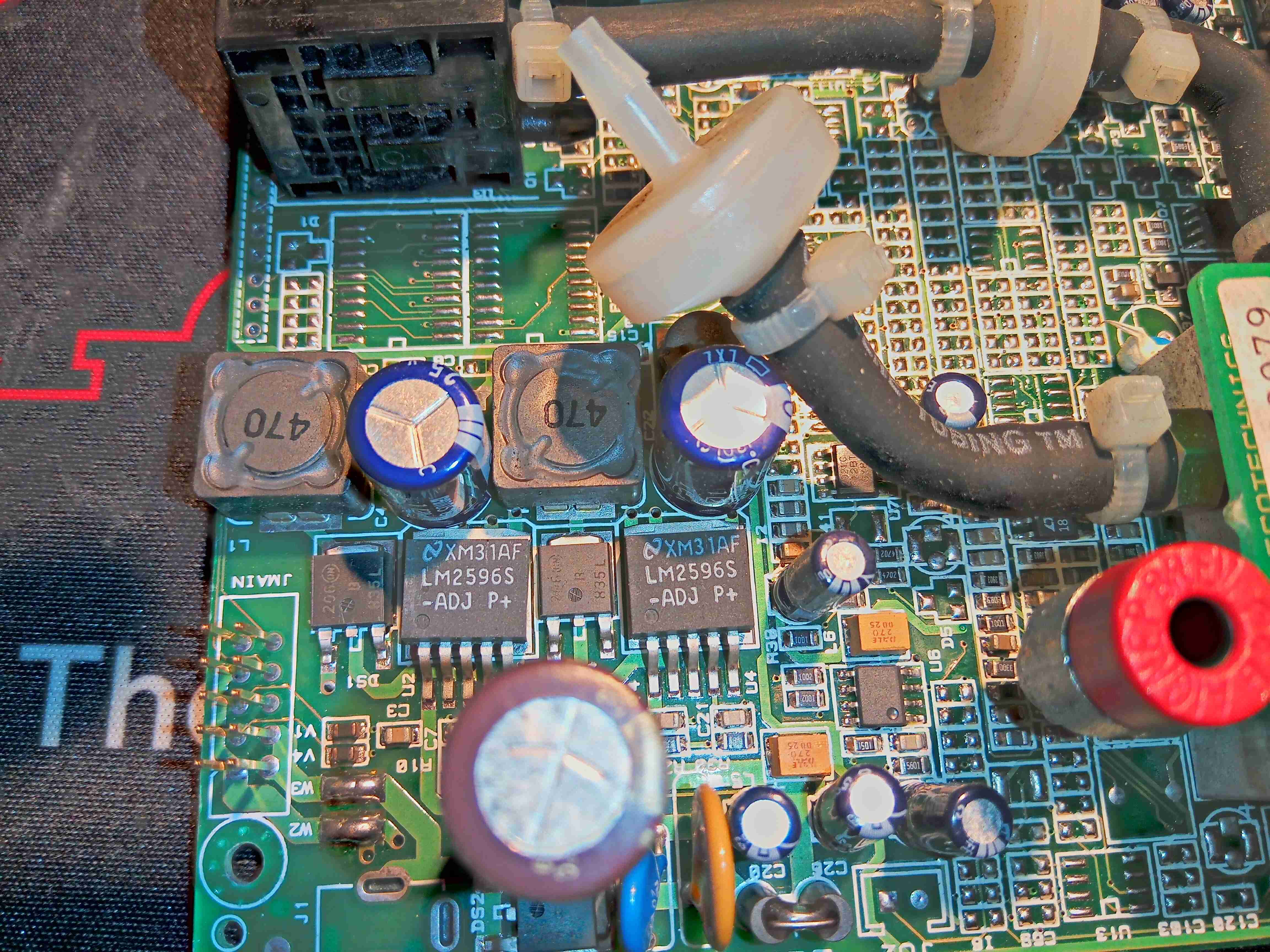
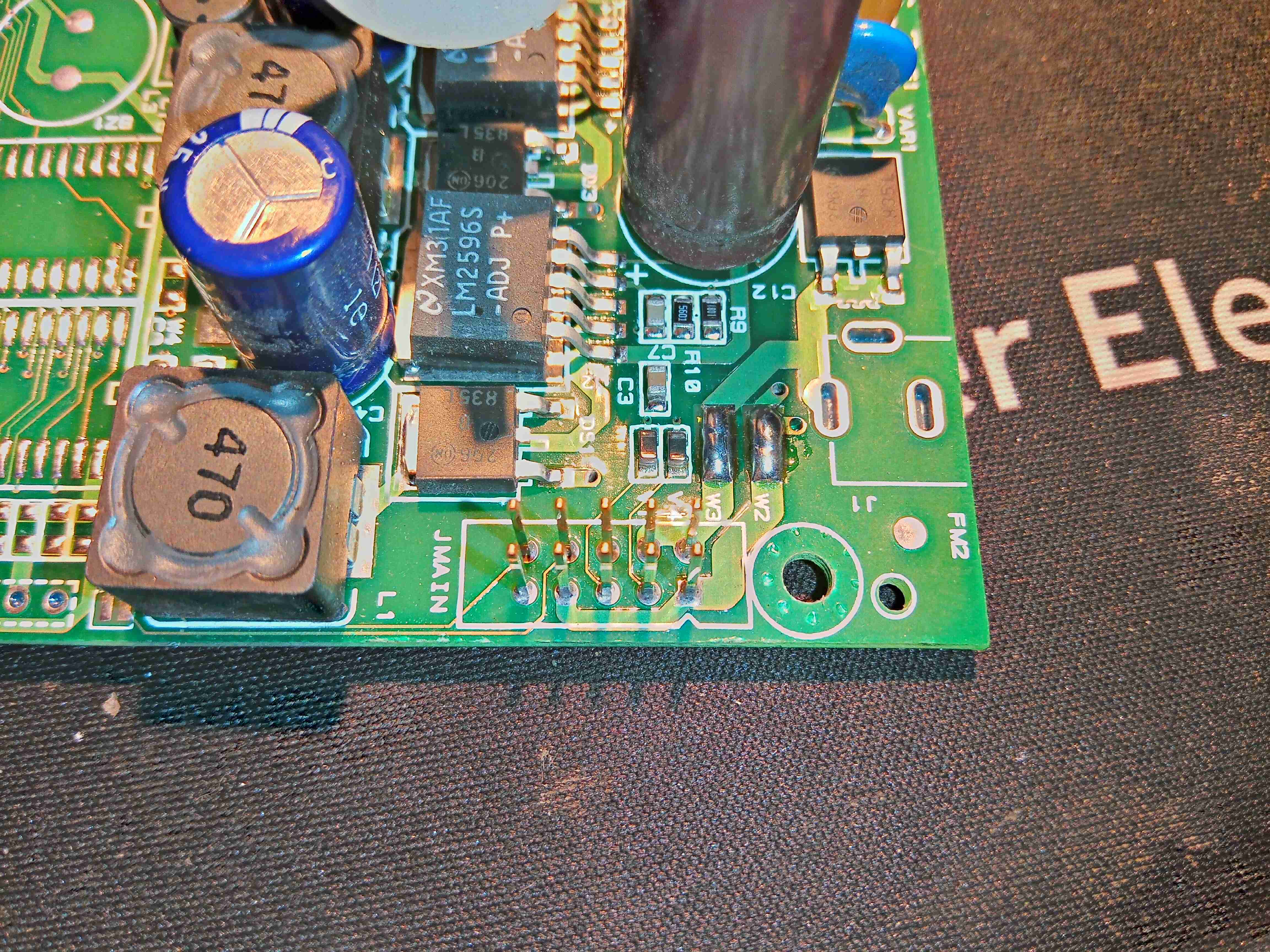
Power Supply
From looking at the input circuitry, I can surmise that the input voltage is somewhere between 12-24v DC, as there is a 35v input electrolytic filter capacitor. There’s a couple of switching regulators which generate 5v & 3.3v rails for the board, with some input fusing.
Main Connector
There’s two serial links on this board, driven from the main microcontroller – the primary one is on the connector marked JMAIN, along with the power input & a couple of other unknown signals.
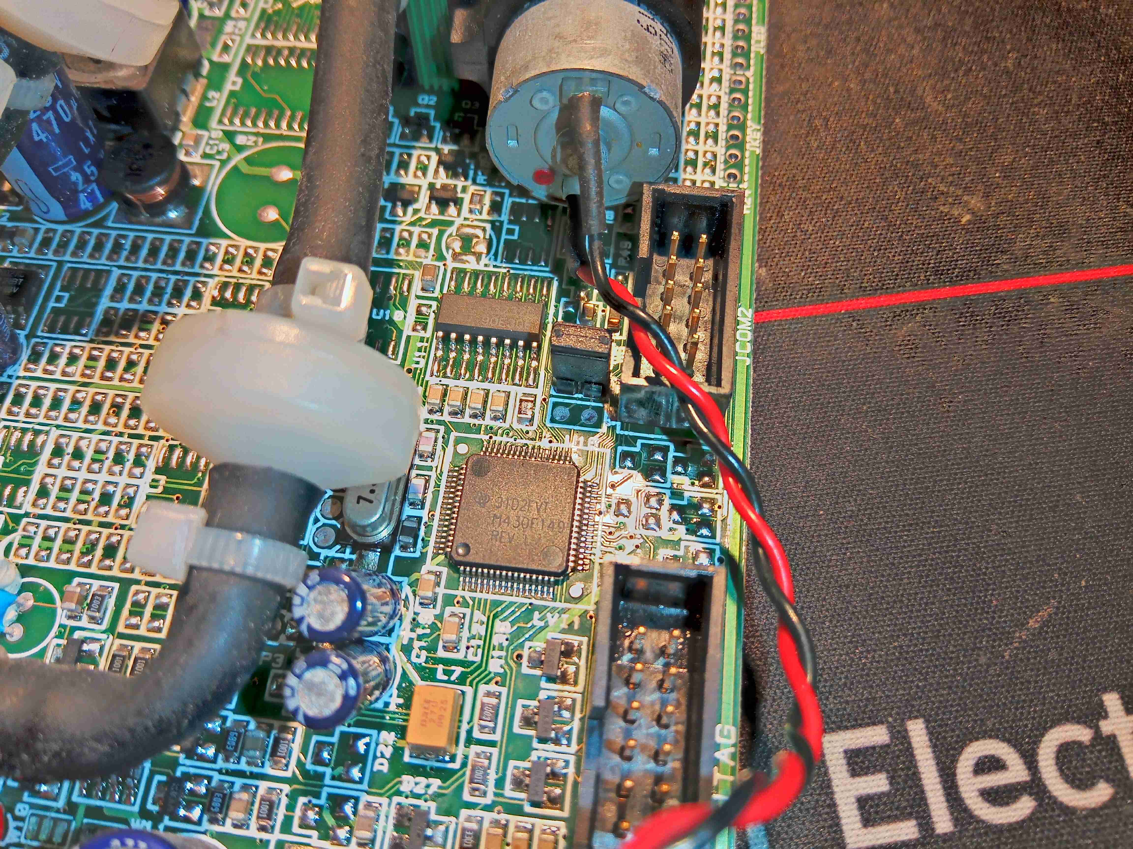
MSP430 Microcontroller
Over on the other side of the board is the brains of the operation – an MSP430 microcontroller, with an RS232 transceiver IC & another RS-232 port marked COM2. The remaining connector is a JTAG port for the micro.
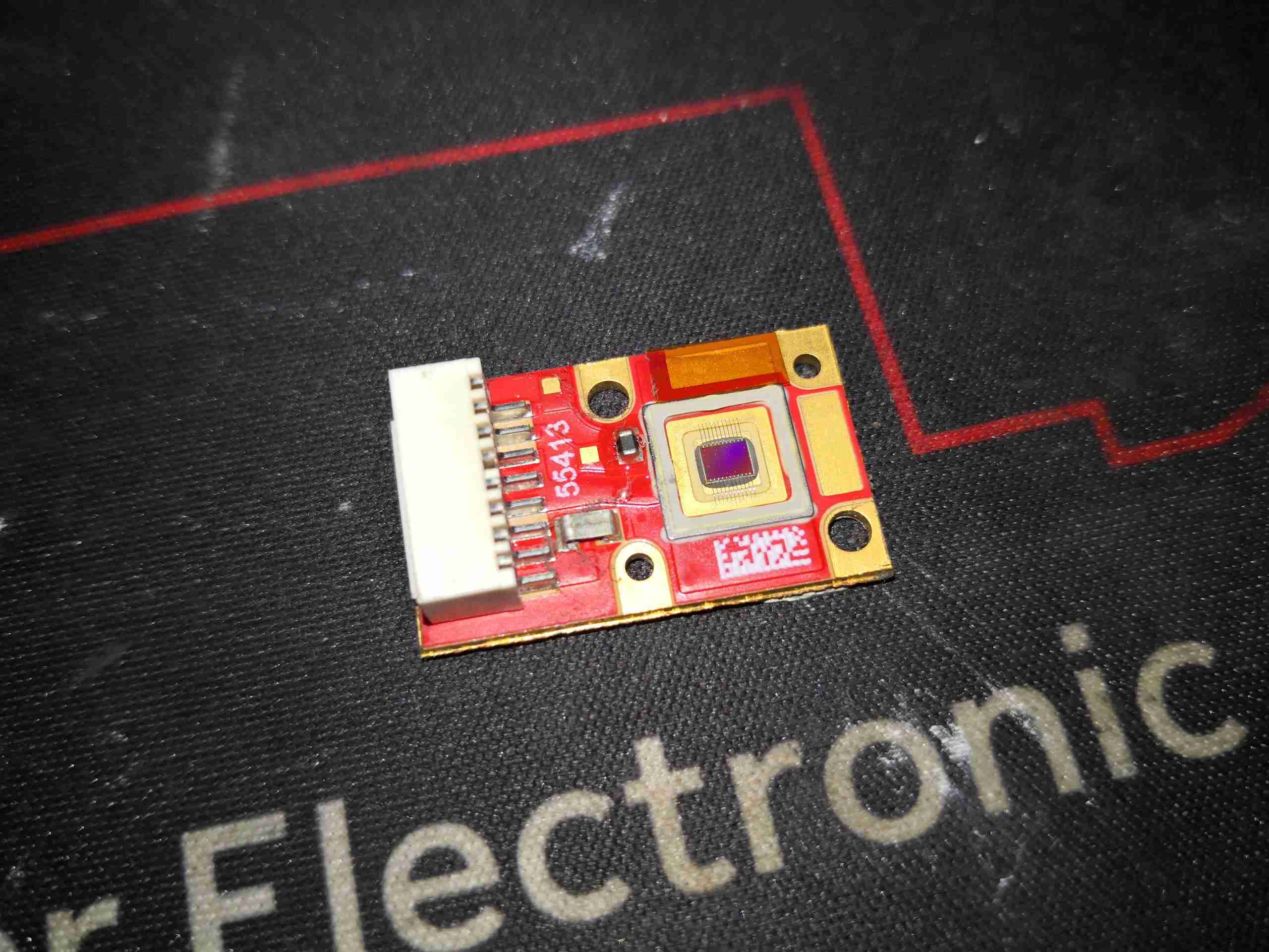
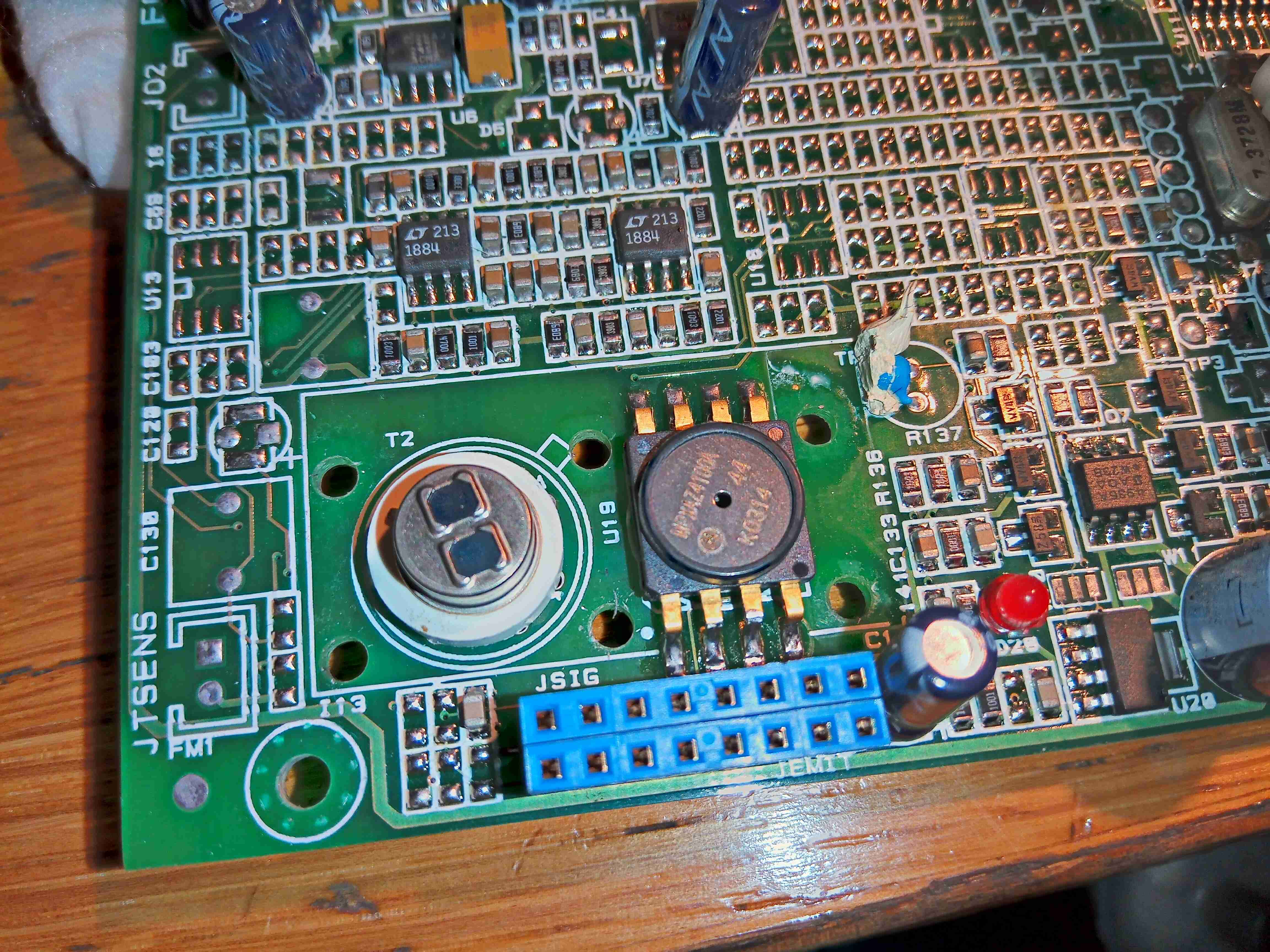
Gas Analysis Cell
Here’s the gas analyser cell itself, sandwiched under another board. There’s a temperature sensor on the side of the cell at the bottom, and even though there’s many pins on the header here, only a couple are actually used for the IR emitter.
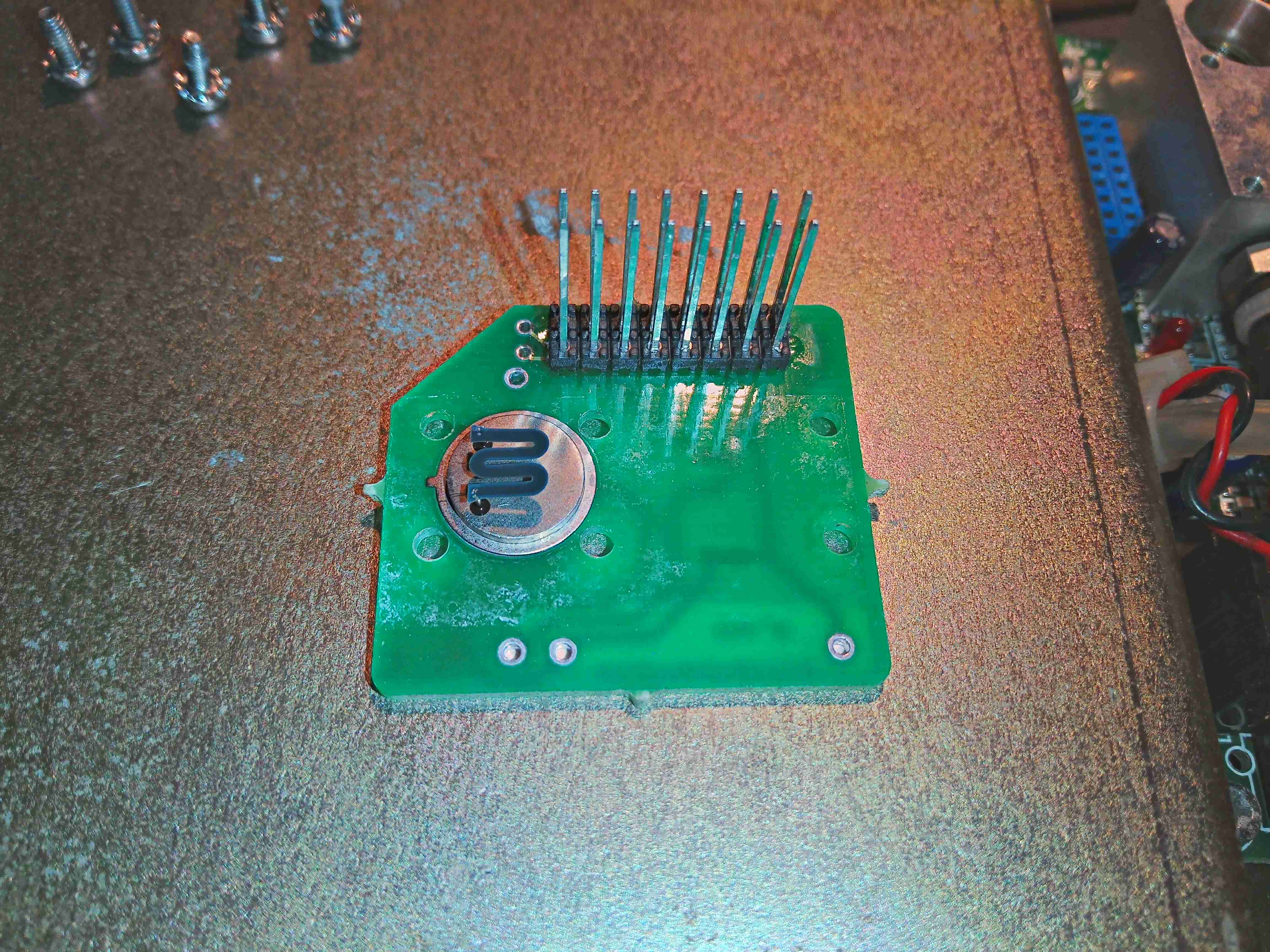
IR Emitter
Removing the screws from the top allows the board to be removed, which exposes the Mid-IR emitter component with an exposed element. This looks to be very fragile, so I won’t be messing with this much. From metering the connections, this appears to be driven at about 2v from the microcontroller.
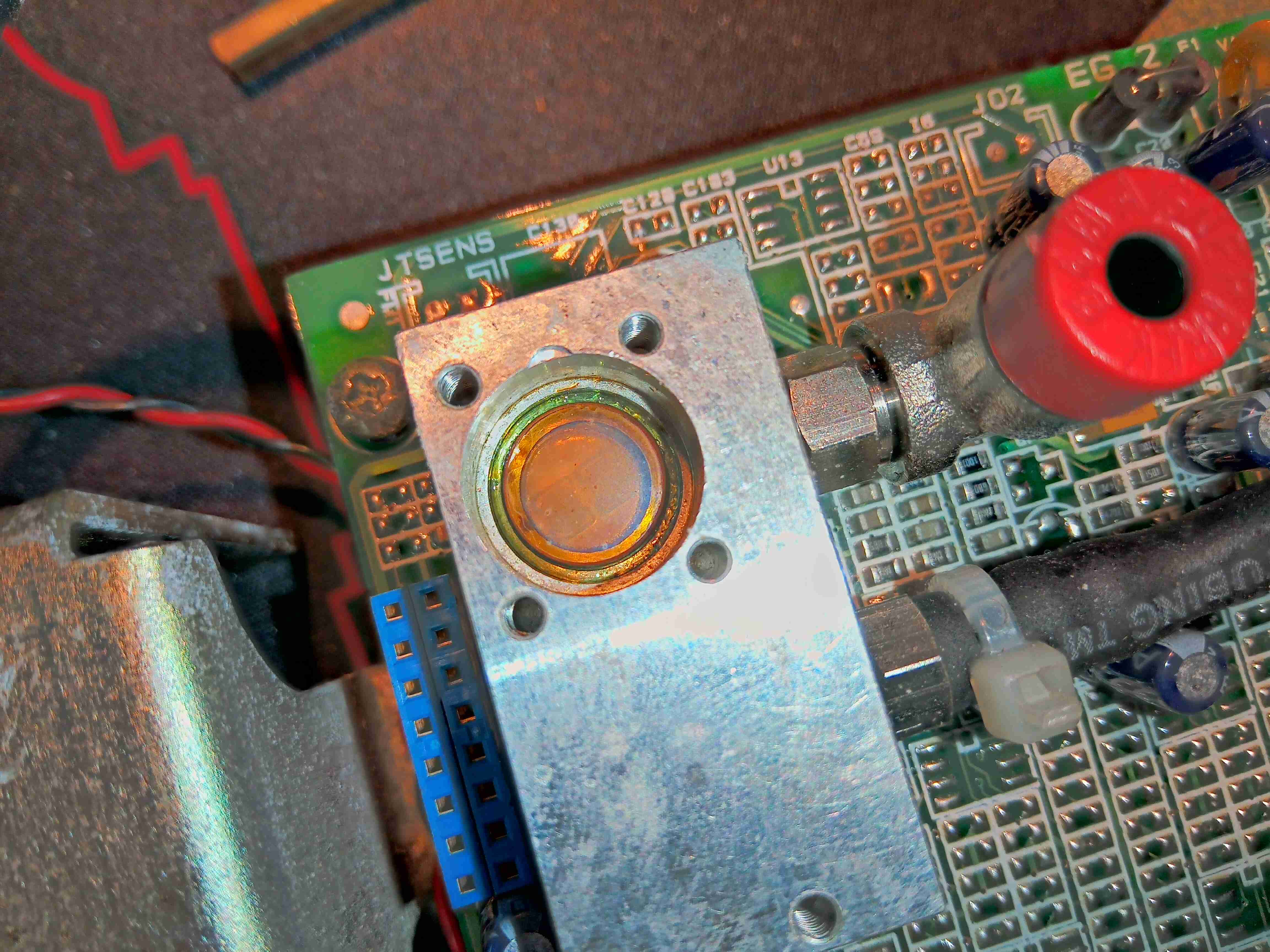
Top Of Gas Cell
The window into the gas cell looks to be made of something exotic – considering the IR application & the colour, this is probably Zinc Selenide.
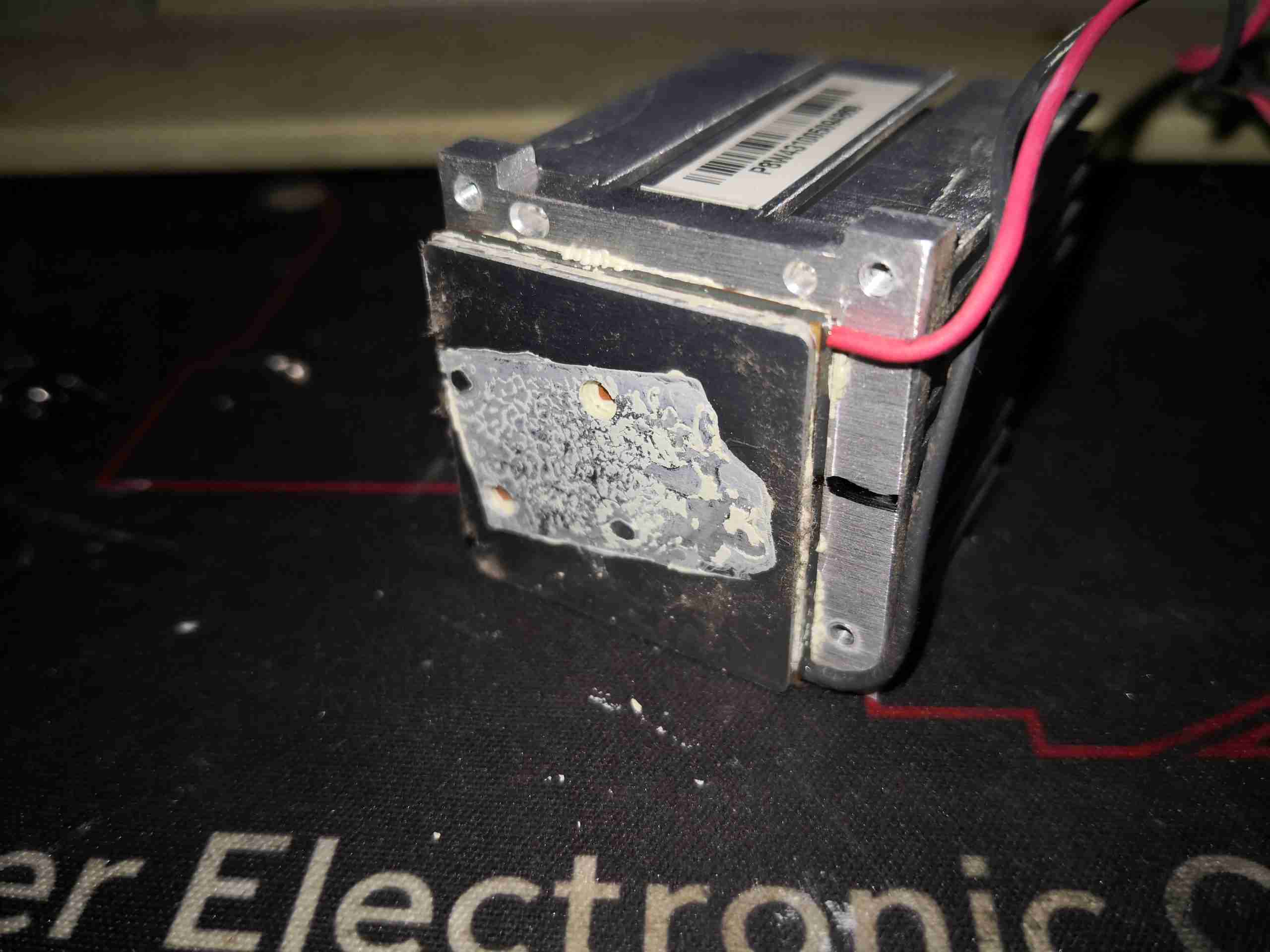
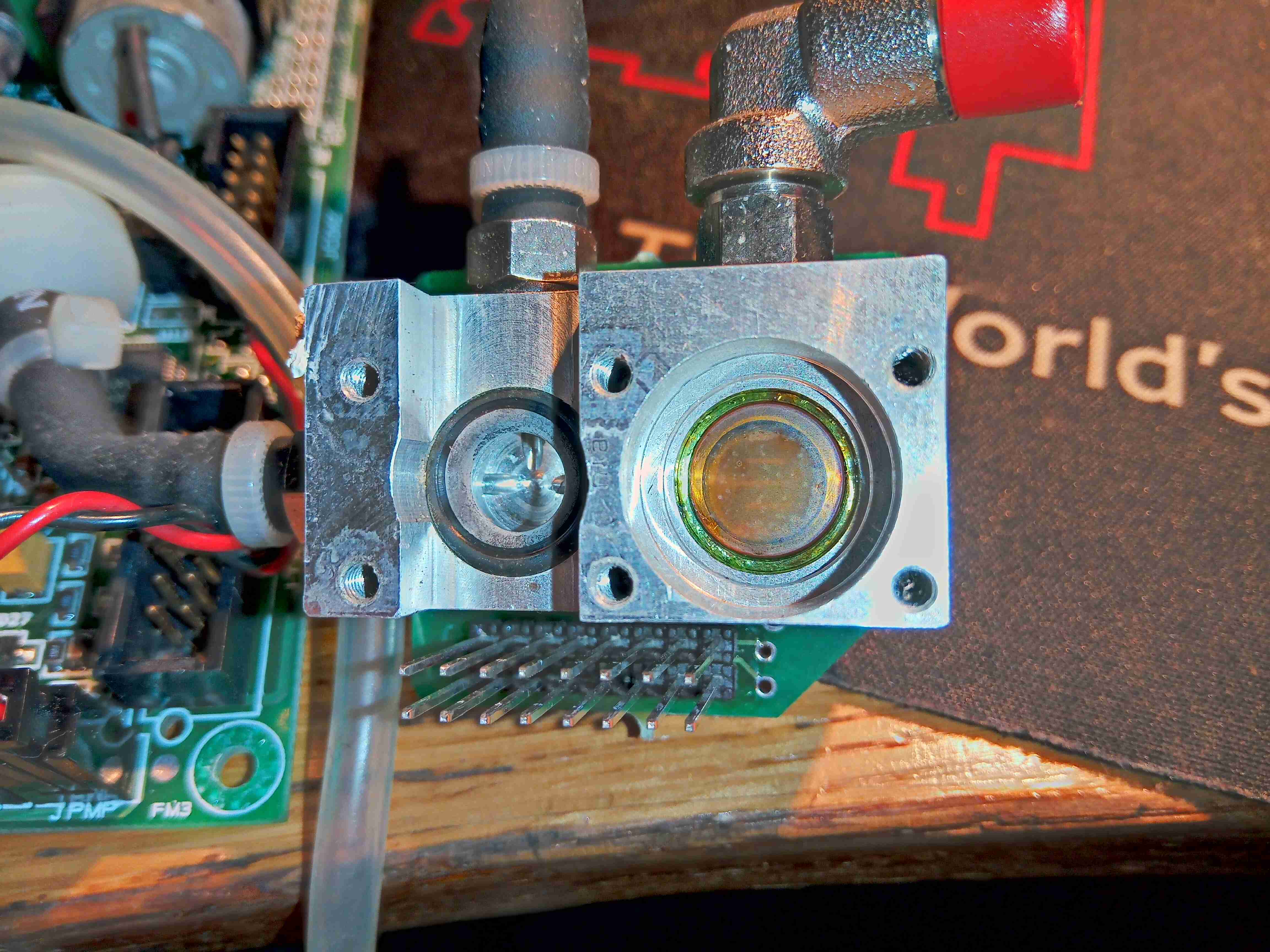
Gas Test Cell
Removing some more screws on the bottom exposes the bottom of the cell with another IR window, and an O-Ring where a pressure sensor sits.
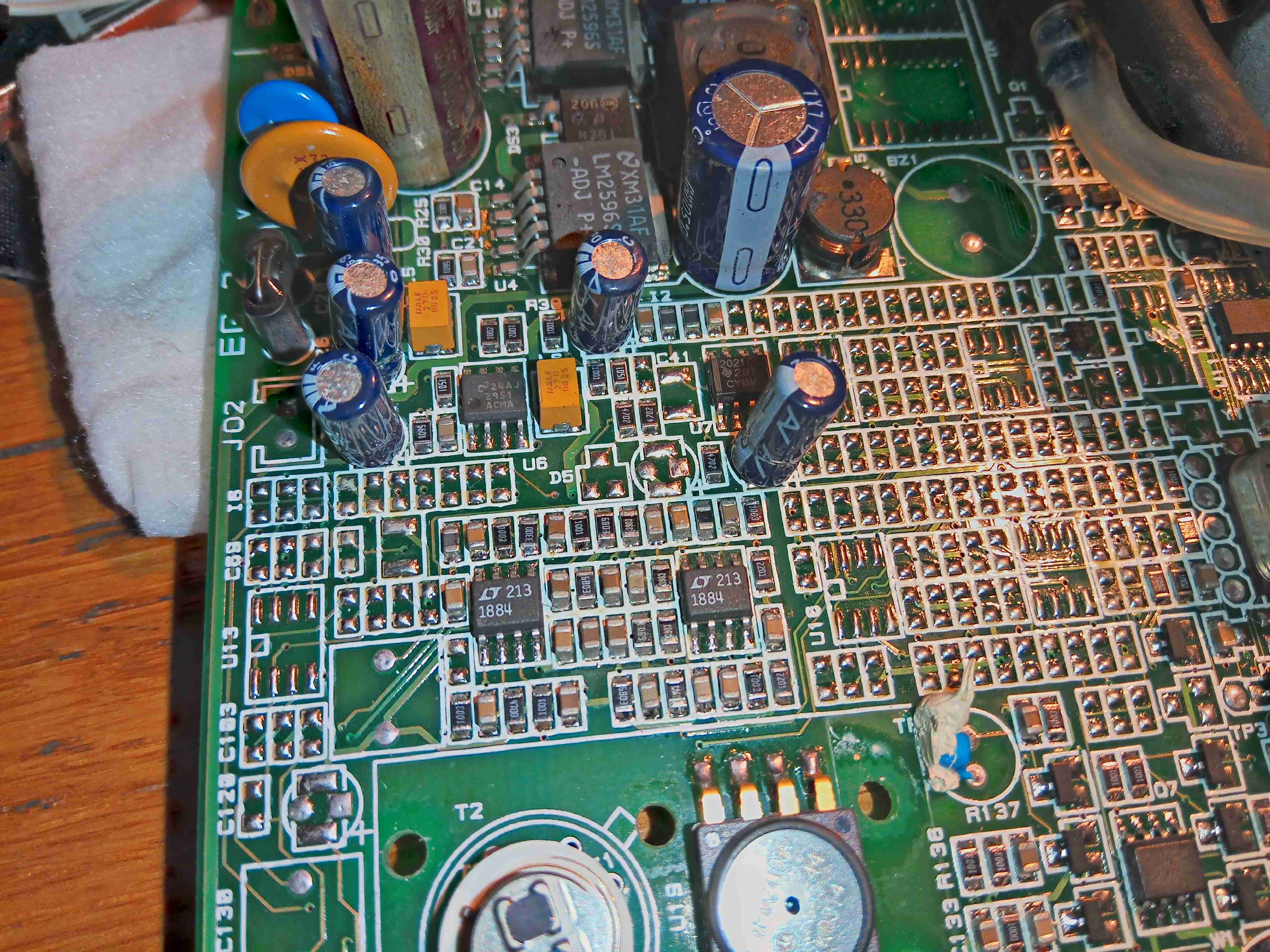
Output Amplifiers
There’s a couple of very accurate LT1884 Rail-To-Rail Precision Op-Amps next to the cell, most likely used to measure the output from the sensor itself.
Mid-IR Sensor & Pressure Sensor
Finally, there is a dual-window thermopile sensor, and a pressure sensor. I wasn’t able to get any information on either of these, but I did find some ranges of sensors for Mid-IR measurement operations, that mentions a wavelength around 10µm for R-134a spectroscopy.
I will try to get this module going & measuring some gases, if I can work out how to talk to it – I already know the serial lines so it’s just working out a command set. If anyone has any information on these, please do get in touch! A service manual for the refrigerant machine this came out of would be good!
Tip Jar
If you’ve found my content useful, please consider leaving a donation by clicking the Tip Jar below!
All collected funds go towards new content & the costs of keeping the server online.