Here’s the CRT circuitry from a tossed STVG-502 Karaoke Machine, which got a good soaking in Manchester’s brilliantly wet weather before I managed to get hold of it:
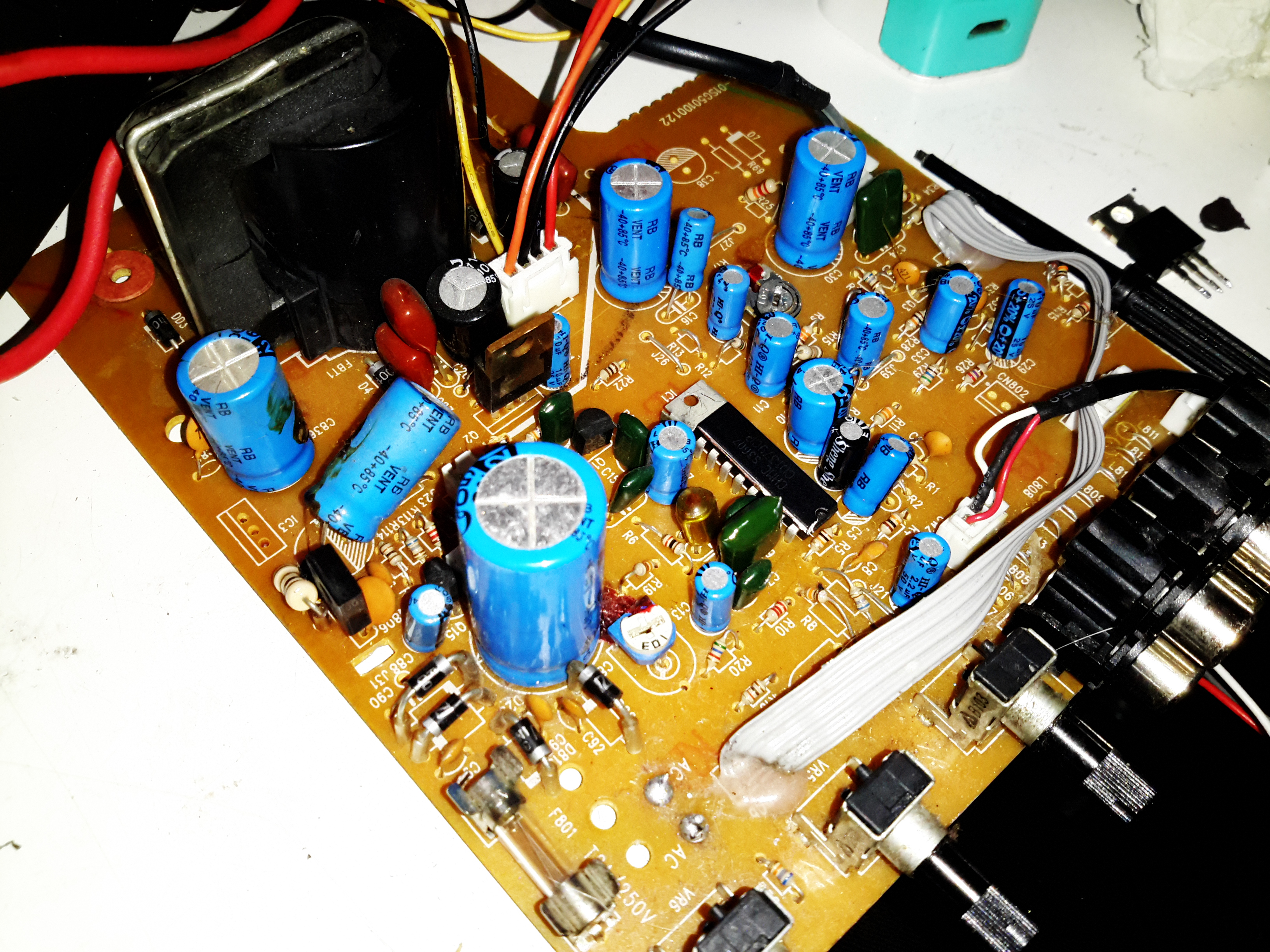
I didn’t do a full teardown of this unit, since it was soaking wet & smelled rather badly of sour milk, so instead I quickly gutted it for the useful parts. These machines are a combination of a CD+G player, CRT composite monitor for displaying the CD+G lyrics & a small audio amplifier & 3W speaker. Power is provided from the mains via a transformer, with both 12 & 24v windings. One half of the board has the audio amplifier sections, the other the CRT drive, running from the 12v & 24v supplies respectively. I chopped off the audio section, as that wasn’t needed.
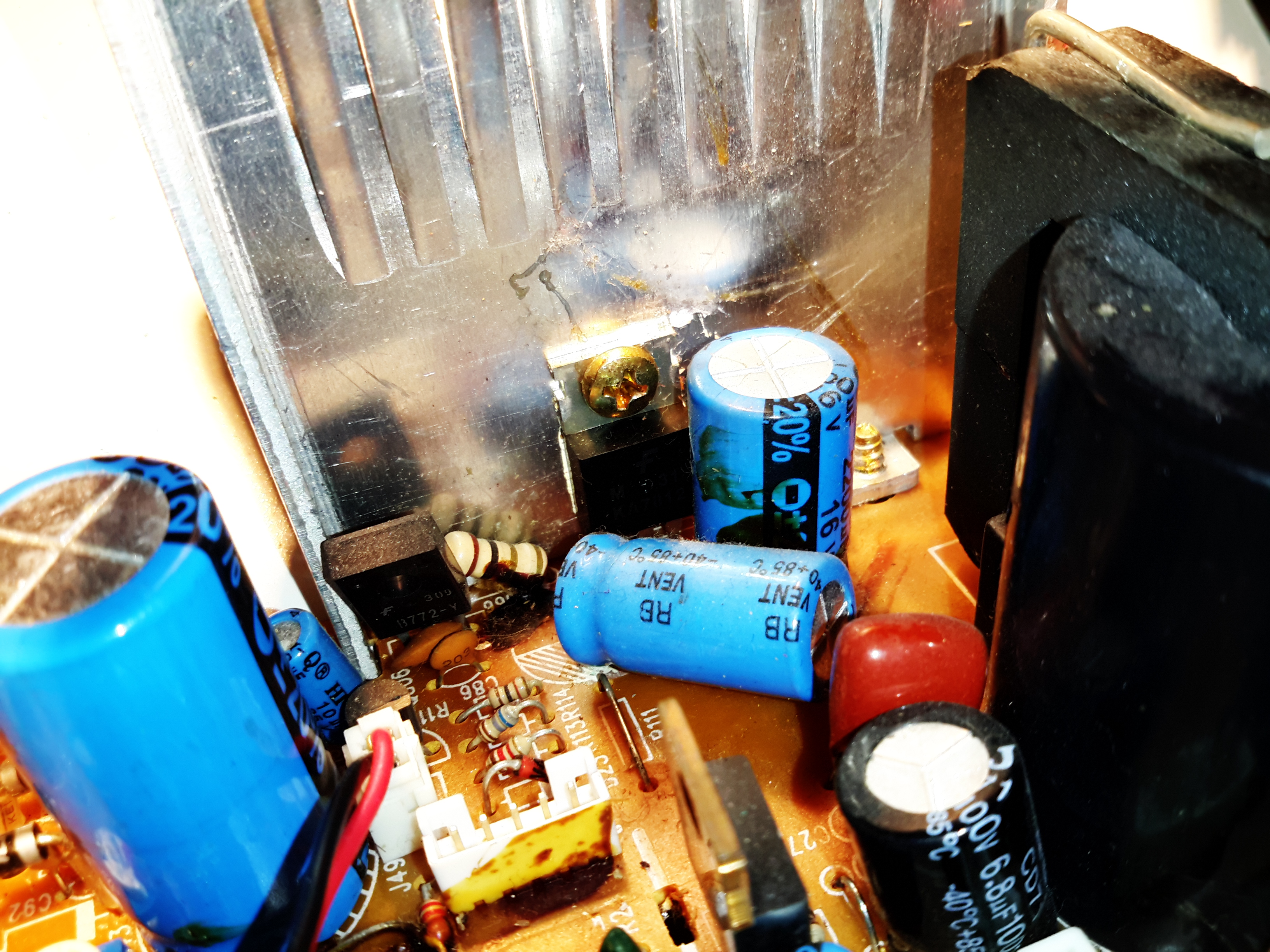
On this huge heatsink is what I originally thought was the horizontal drive transistor is actually a 12v linear regulator – the board gets fed 16v AC. This is then run through a rectifier which will produce an approx 22v rail, and after the smaller transistor on the left used for power switching. The 22v then gets dropped through a 1/2W 1Ω resistor, then the linear regulator drops it down to 12v for the rest of the circuit – dissipating a goodly amount of power in the process.
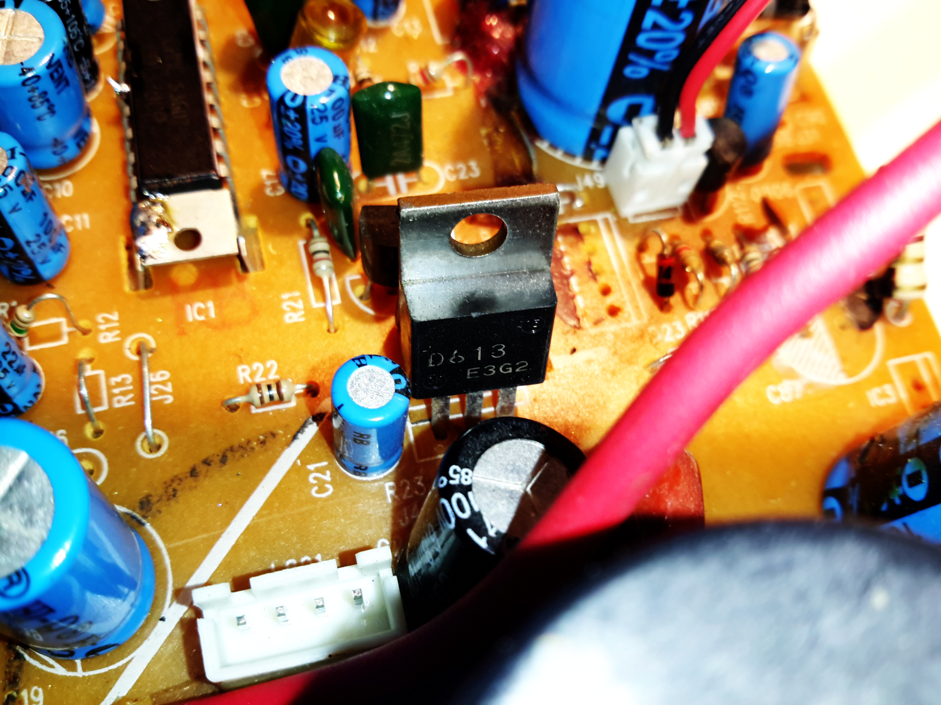
This is in fact the horizontal drive transistor, a 2SD613, which according to the datasheet, is intended for audio amplifier output stage applications, not CRT drive. Regardless, it’s an 85v 6A NPN transistor, and does get a bit on the warm side, but was never given a heatsink from the factory.
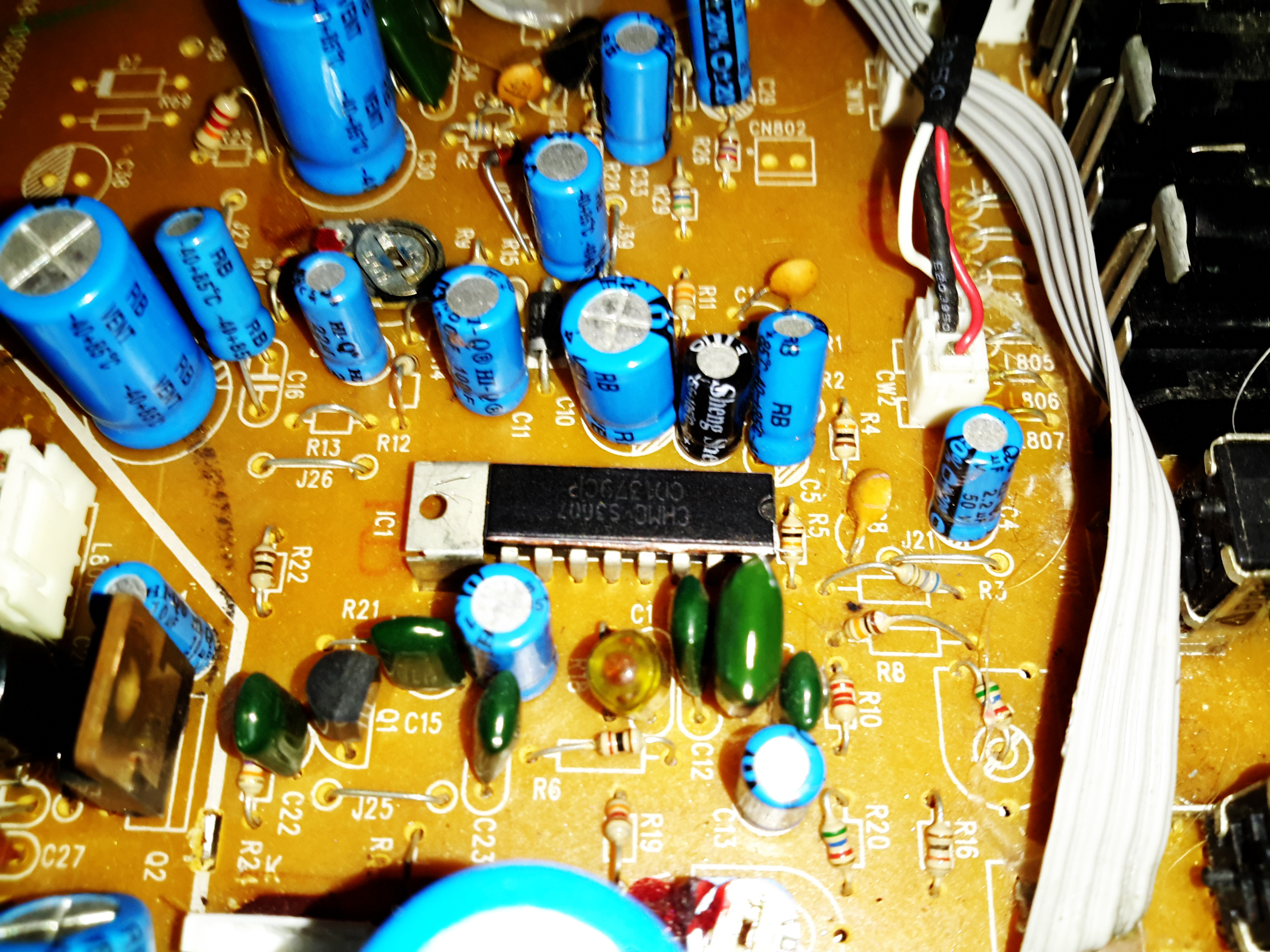
All the drive signals for the CRT are taken care of by this single DIP IC – a CD1379CP from Silicore. Considering the older CRT-based devices I have, with entire boards twice the size of this one dedicated to discrete components required to drive a CRT, this is definitely an advance in technology. Very few external components are being used, and no custom magnetics.
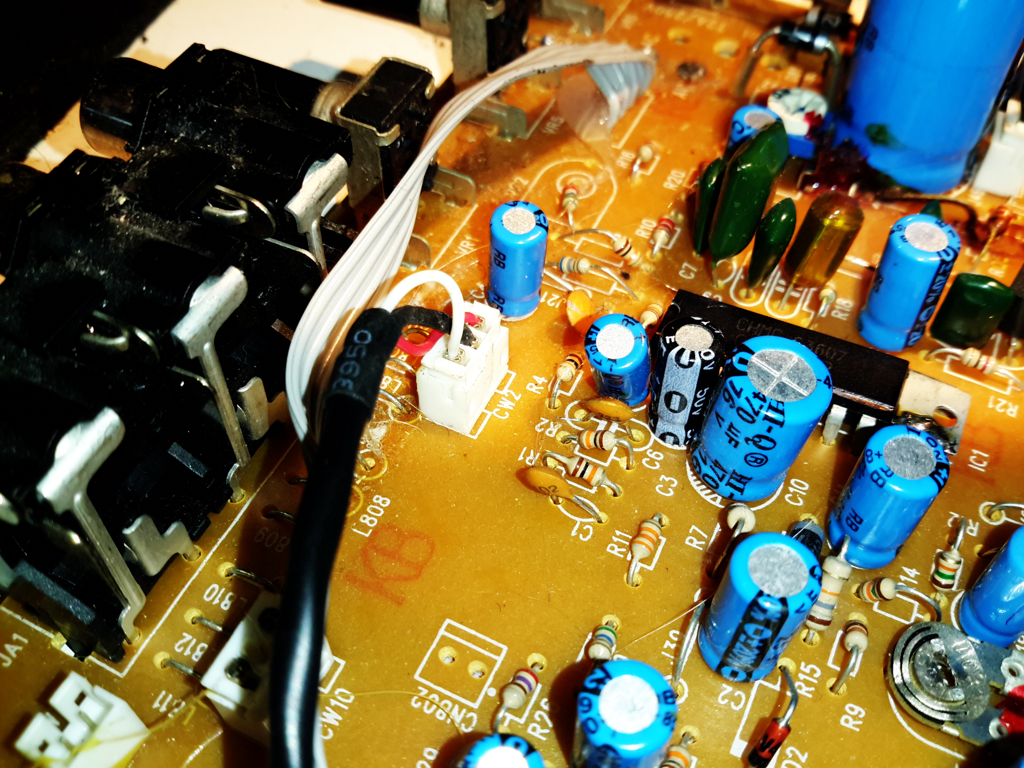
The video signal comes in from the CD+G player module on this connector, it’s a standard composite input. The composite video is fed into an amplifier after the controller IC. This video amp is powered from a 140v rail from the flyback transformer, to give enough signal to drive the CRT cathode.
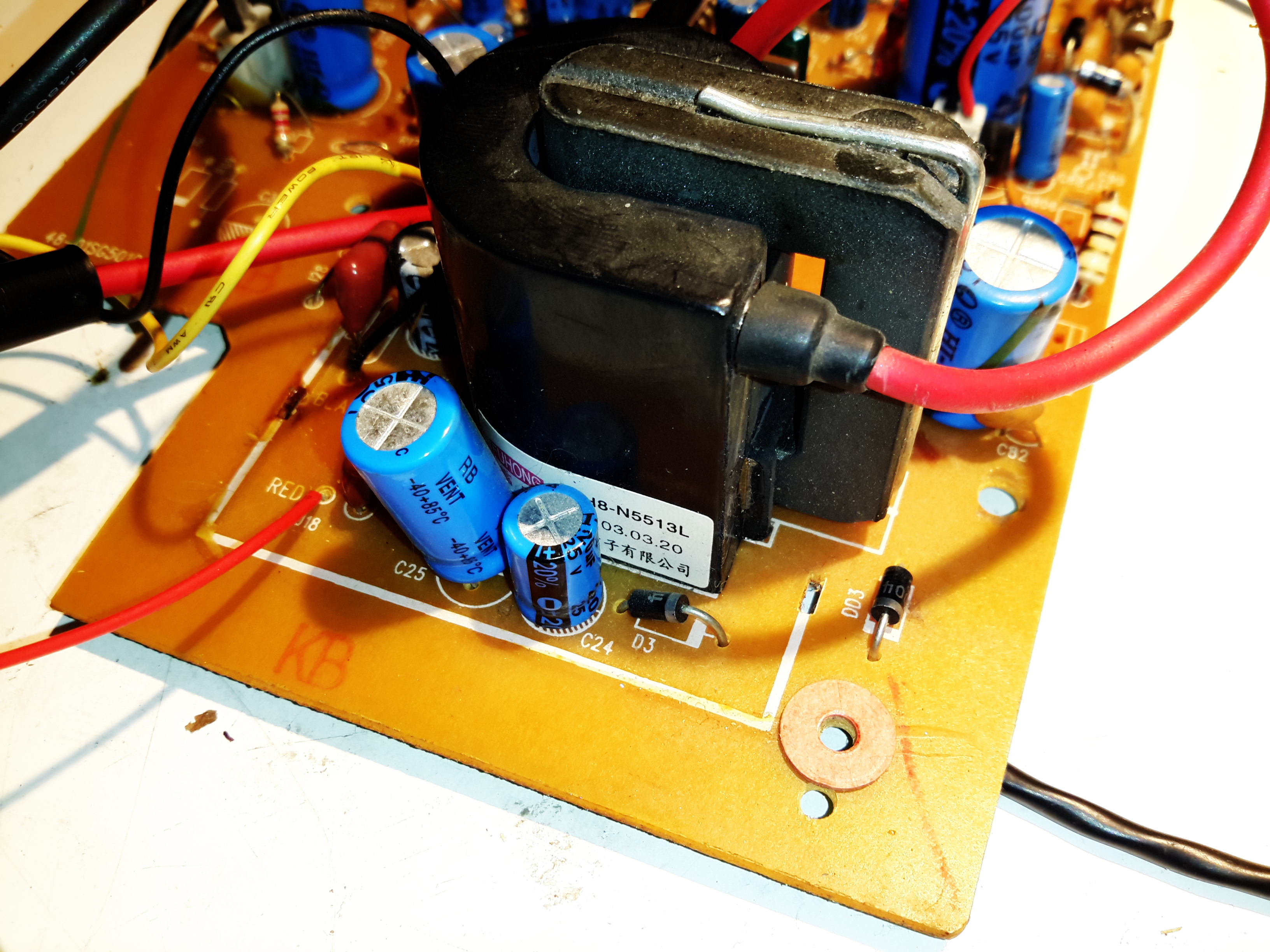
The high voltage transformer is a BSH8-N5513L, I’ve not been able to find any data on this, but it looks like a standard off the shelf transformer from the listings on the Chinese supplier sites. There are very few support components around here, just a couple of diodes to rectify the high voltage focus supply, and no linearity coil. Weirdly, the 1st accelerating anode of the tube is grounded in this circuit. Very few adjustments are provided, most are set with fixed resistors to keep the cost low.
The CRT
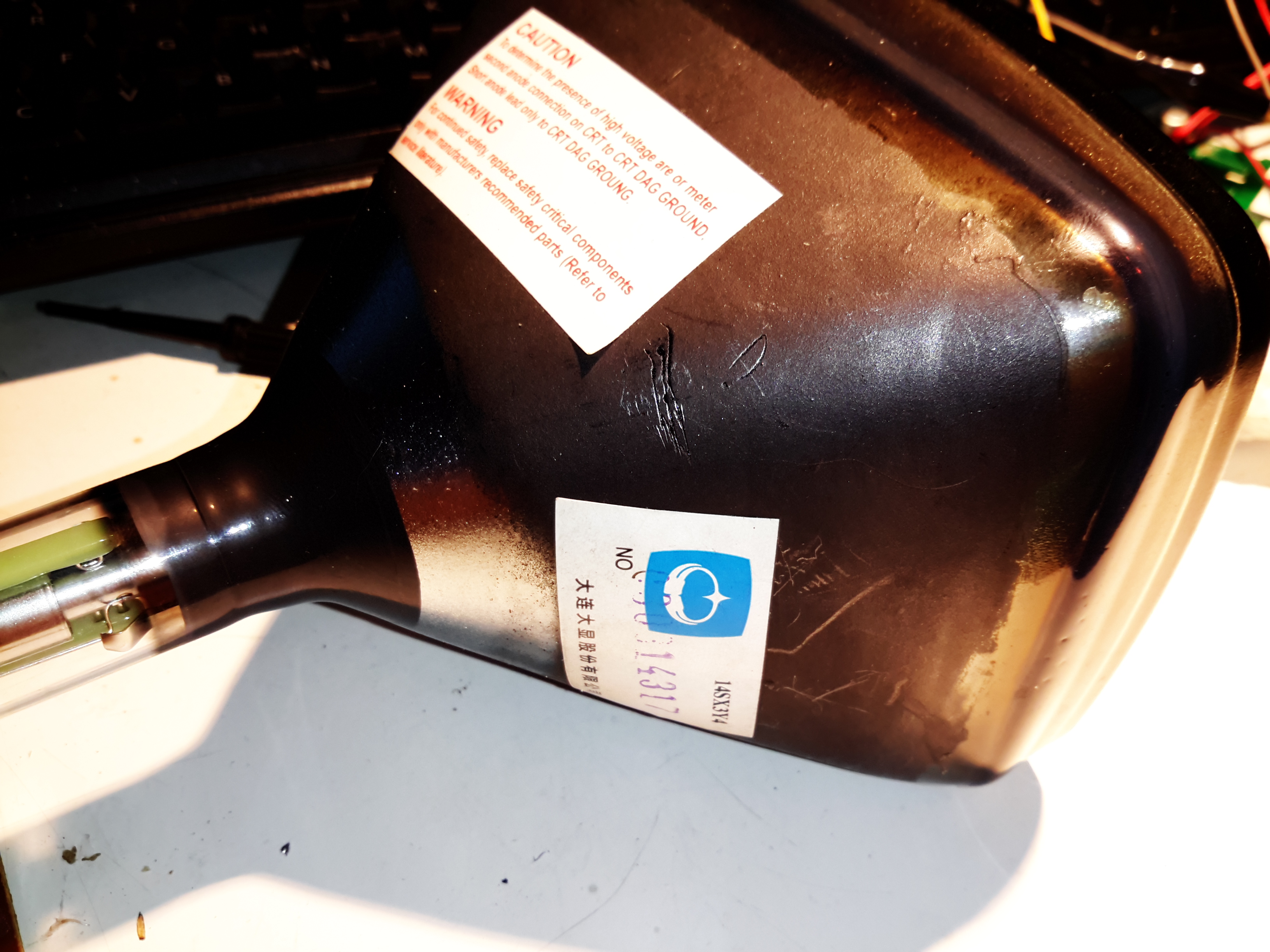
Here’s the CRT, it’s a 5″ monochrome model. I’ve not been able to find much data on this either.
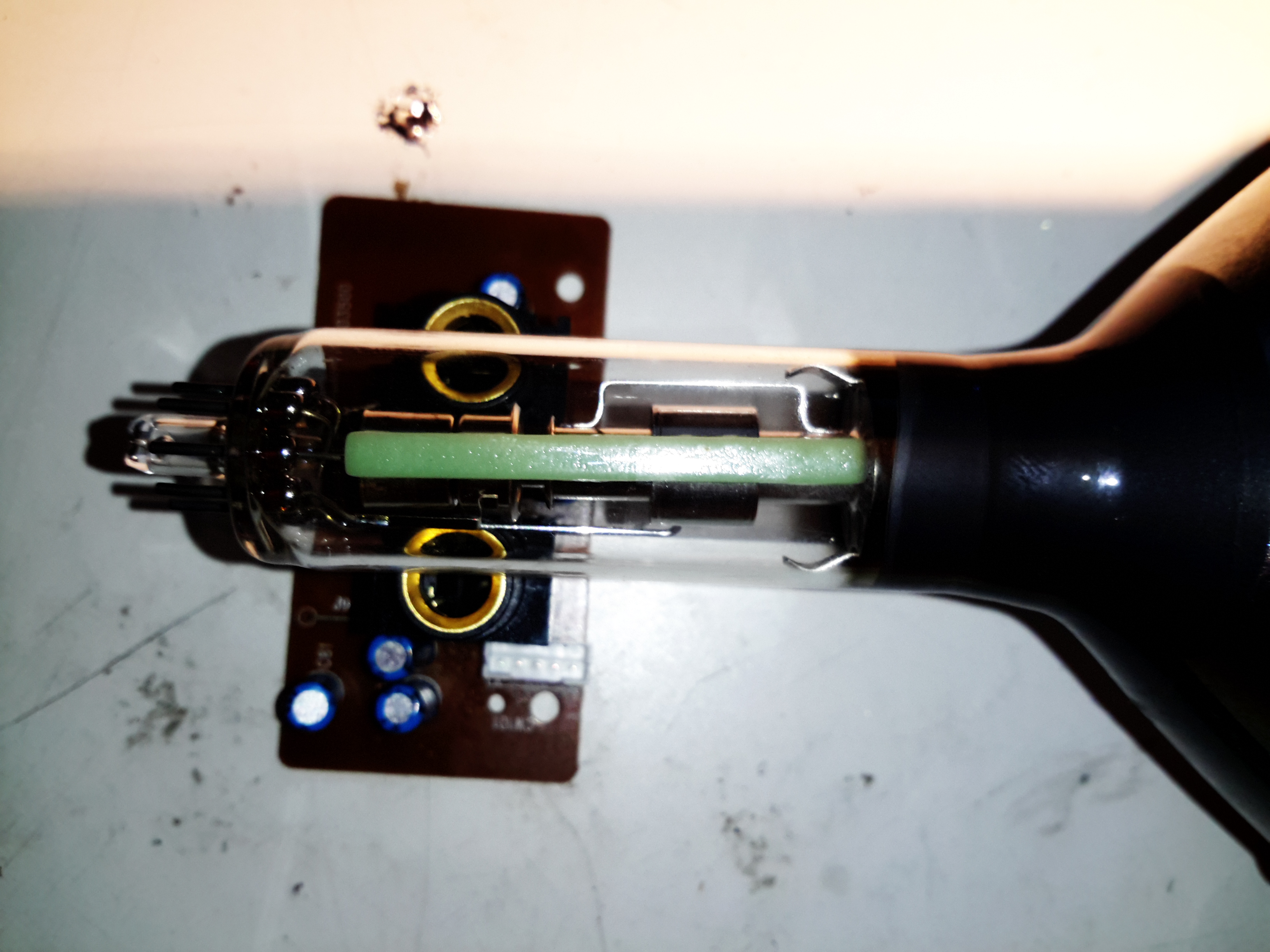
Seems the gents in the Shenzhen factory were having a bit of an off day when this one was made – the electron gun assembly is actually tilted in the neck of the tube – as a result the spot formed with no deflection is far from the centre of the screen. This tube does still produce a pretty good picture though, this manufacturing error is easily corrected for with the positioning magnets on the deflection yoke.
Final Mods
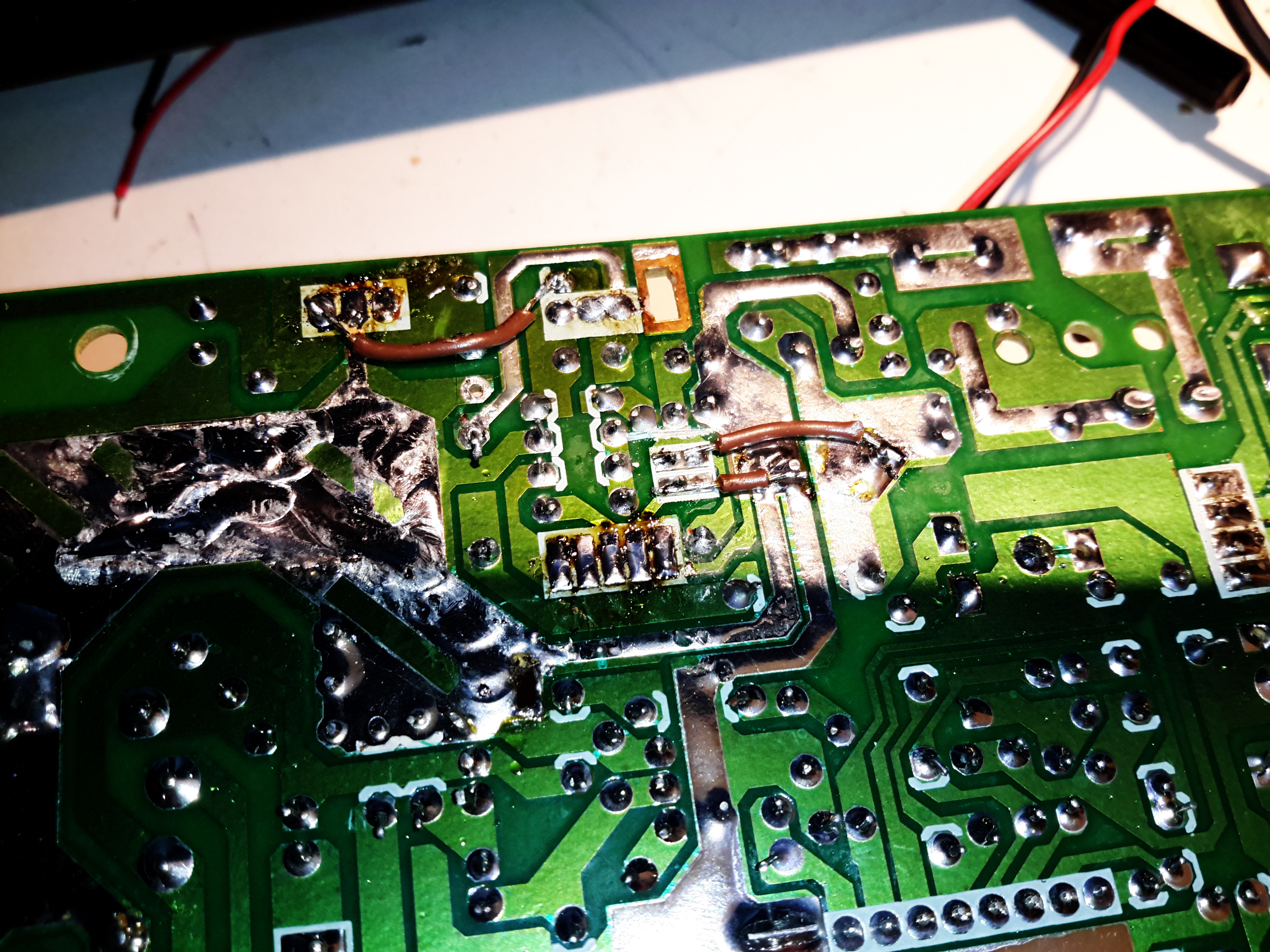
I’ve installed a couple of mod wires on the bottom of the PCB to get this to work outside the original application, without the room heater of a linear regulator in circuit this will run fine from a 12v supply. The PCB quality is a bit naff – even quick heating with a soldering iron makes tracks fall off the laminated paper board.

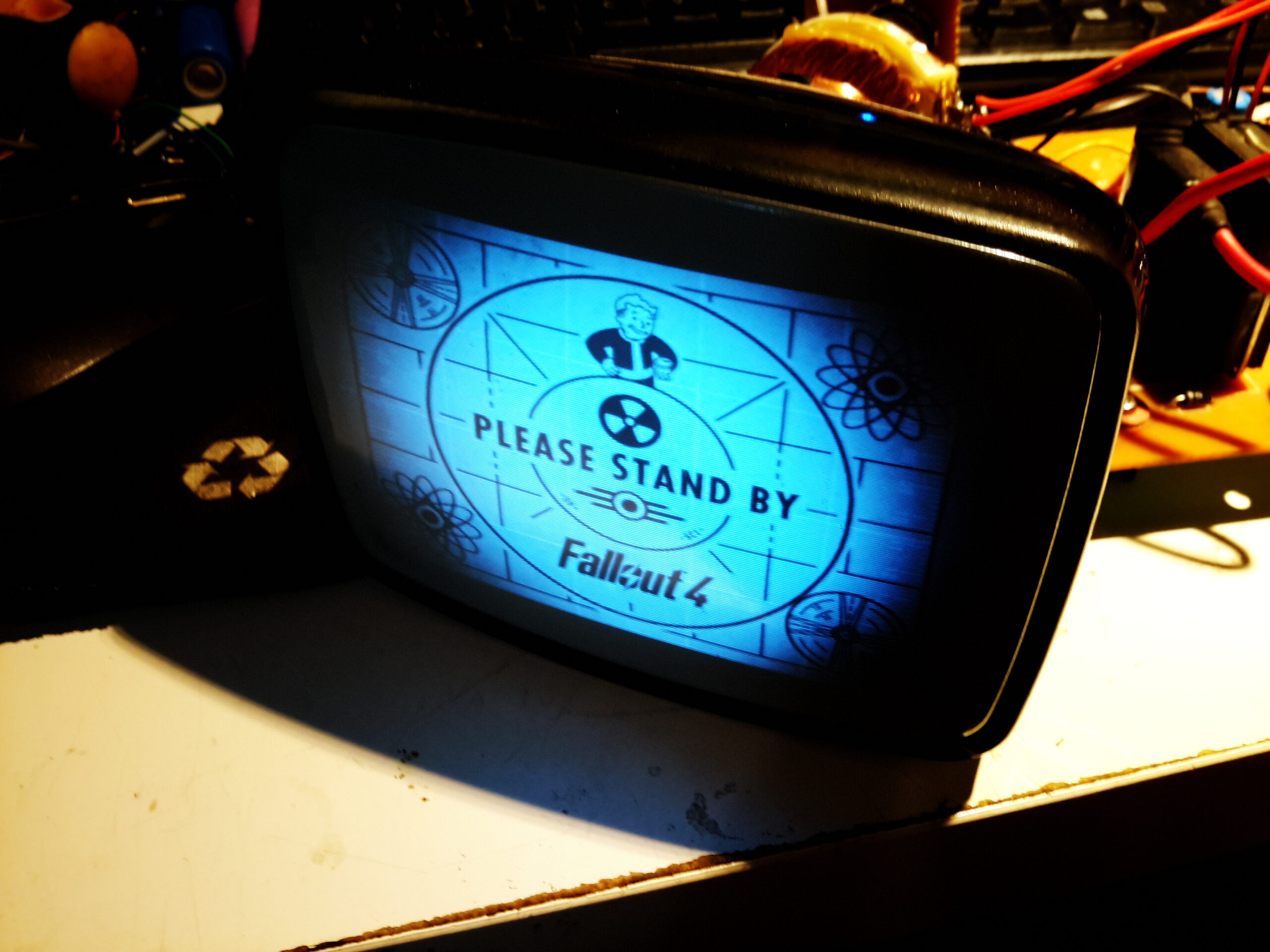
Image quality is surprisingly good for the cheapest CRT-based monitor I’ve ever seen, I figured a Fallout reference was required here; anyone for a proper CRT-based PipBoy? 😉 Shame the phosphor isn’t green.

I do have this CRT short data.. in taobao i bought a green version before the factory close..
Filament voltage : 12V Filament current :75mA
Typical operation:
Final anode : 8KV
Vg2 : 100V there also have 300V version
Vg1 : -35V +/- 10V
There also have a focus grid i remember the focus grid is connect to ground.. This are tetrode electron gun the final voltage 8KV will work well at lower voltage just the brightness will decrease.
I have make some magnetic CRT experiment if you interest you can visit my webpage:
https://geeseang.wordpress.com/experimenting-scan-coil-for-radar-crt2014/
I have few of 04JM Sony flat CRT having filament of 0.6V 0.3A final anode require 6-7KV .. thinking to use it to make a small TV
No speak English. Im from Poland. Ja też mam ten kineskop i tak samo wygięta jest szyjka kineskopu, więc prawdopodobnie była cała seria takich. Pozdrawiam.
Do you have any insight on how to do the same on the stvg-500. Not sure where you put your jumper wires. The pcb is not the exact same but very similar.