Here’s another Dyson teardown, in my efforts to understand how marketing have got hold of relatively simple technology & managed to charge extortionate amounts of money for it.
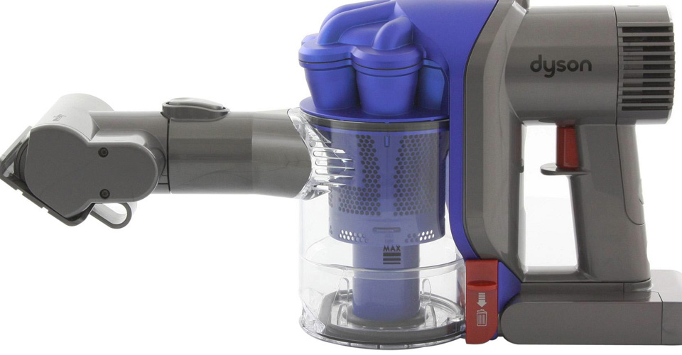
This is the DC35, the model after the introduction of the brushless digital motor.
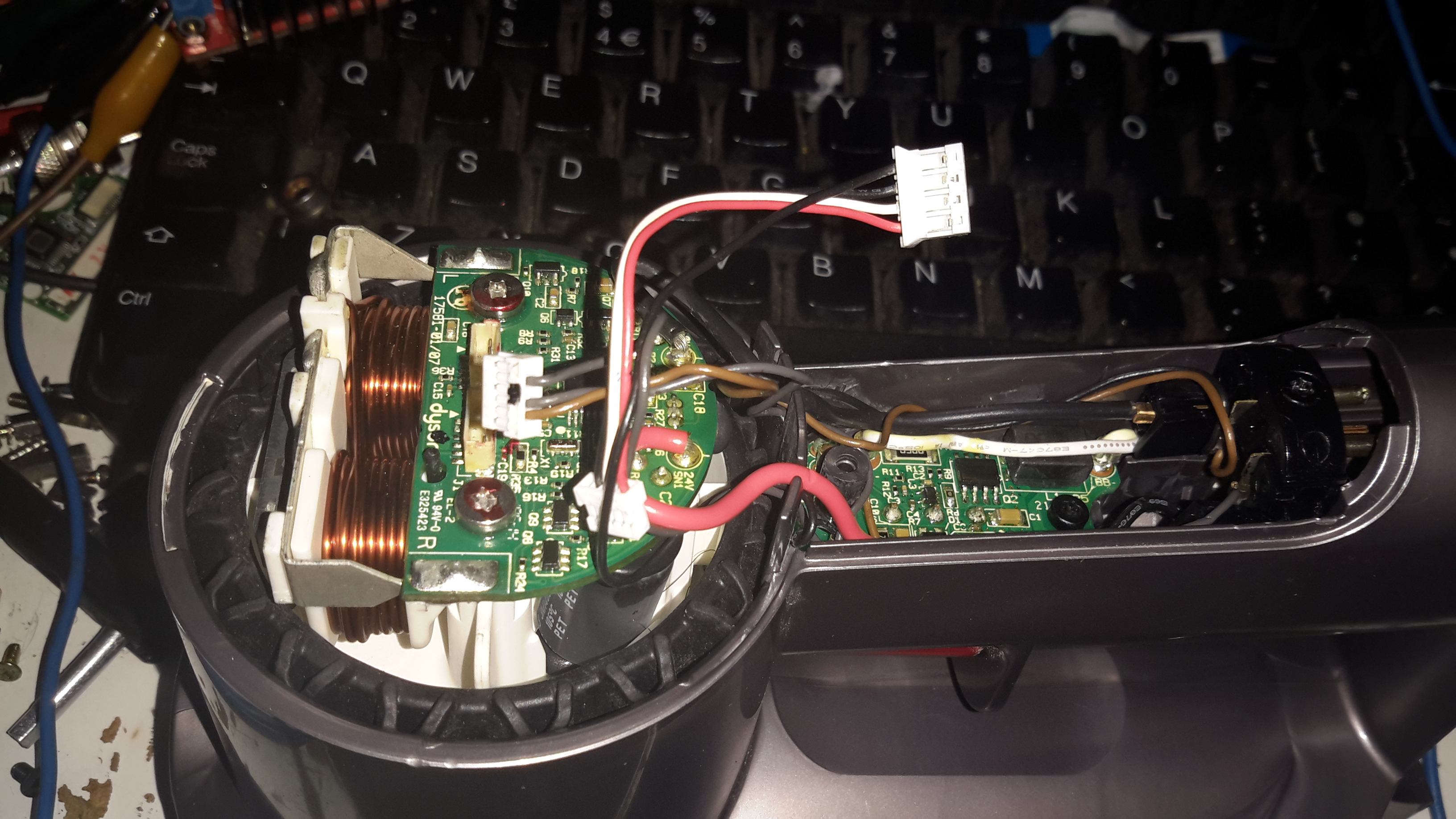
On this version the mouldings have been changed, and the back cover comes off, after removing the battery retaining screw. It’s attached with some fairly vicious clips, so some force is required. Once the cap is removed, all the electronics are visible. On the left is the motor itself, with it’s control & drive PCB. There’s another PCB on the trigger, with even more electronics. The battery connector is on the right.
Here’s the trigger PCB, which appears to deal with DC-DC conversion for powering the brush attachments. The QFN IC with yellow paint on it is an Atmel ATTiny461 8-bit microcontroller. This is probably controlling the DC-DC & might also be doing some battery authentication.
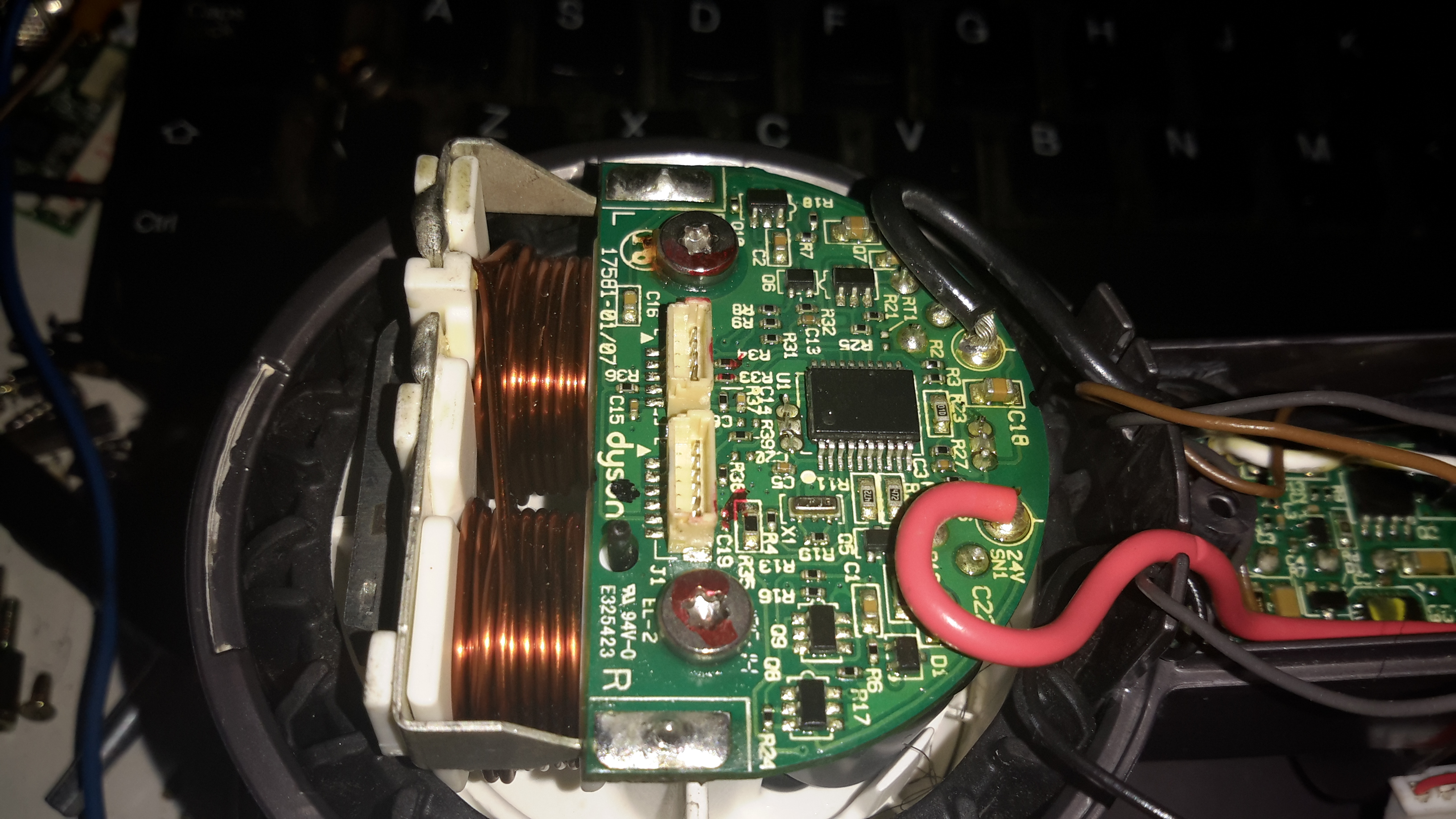
Here’s the motor & it’s board. The windings on the stator are extremely heavy, which makes sense considering it’s rated at 200W. The main control IC is a PIC16F690 from Microchip. Instead of using an off the shelf controller, this no doubt contains software for generating the waveforms that drive the brushless motor. It also appears to communicate with the other PCBs for battery authentication.
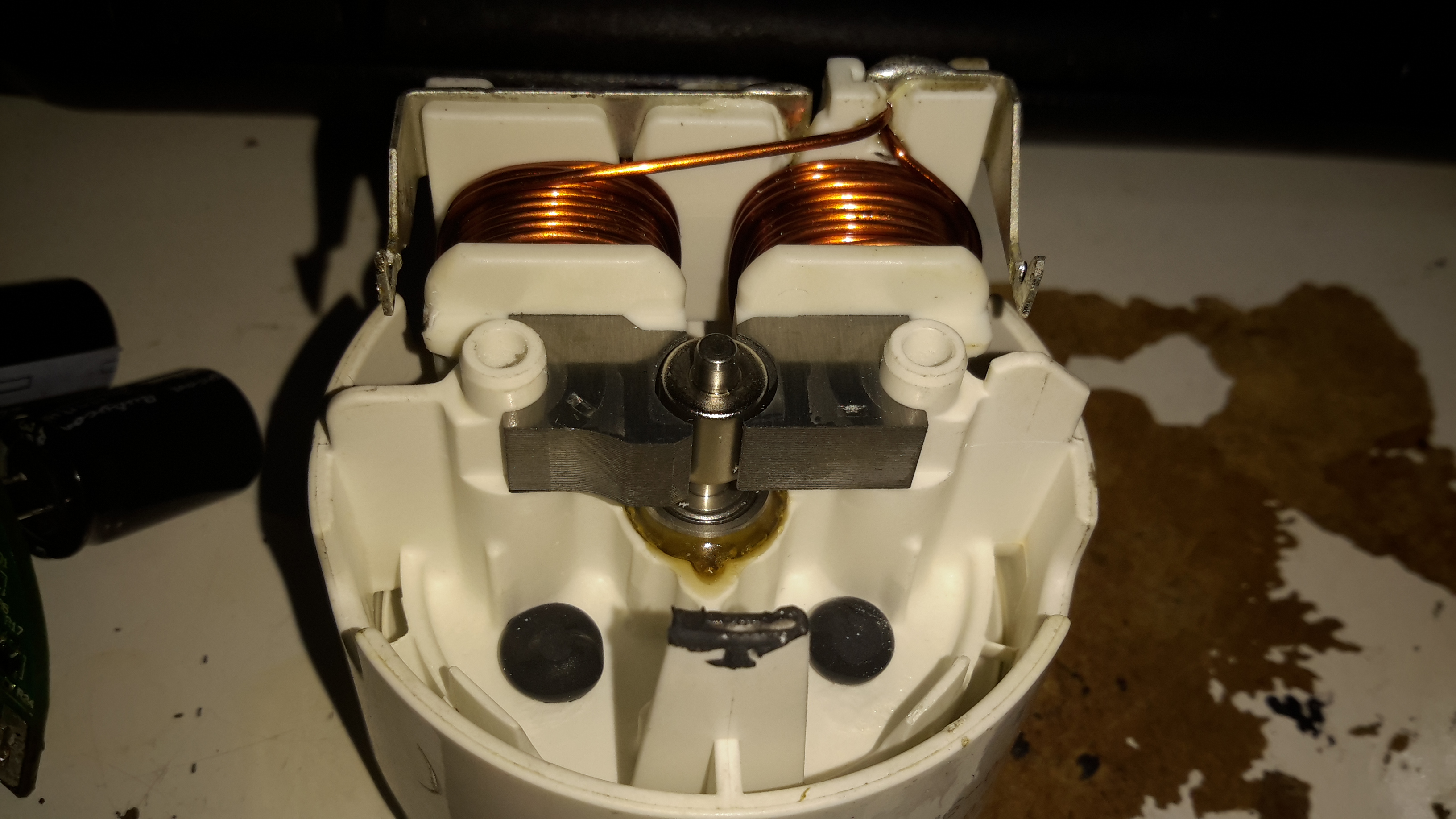
Desoldering the board allows it to be removed from the motor itself. The pair of windings are connected in anti-phase, to create alternating North-South poles depending on polarity. Since the existing controller is unusable due to software authentication with the other parts, I might have a go at building my own driver circuit for this with an Arduino or similar.
The blower assembly is simple plastic mouldings, pressed together then solvent welded at the seam.
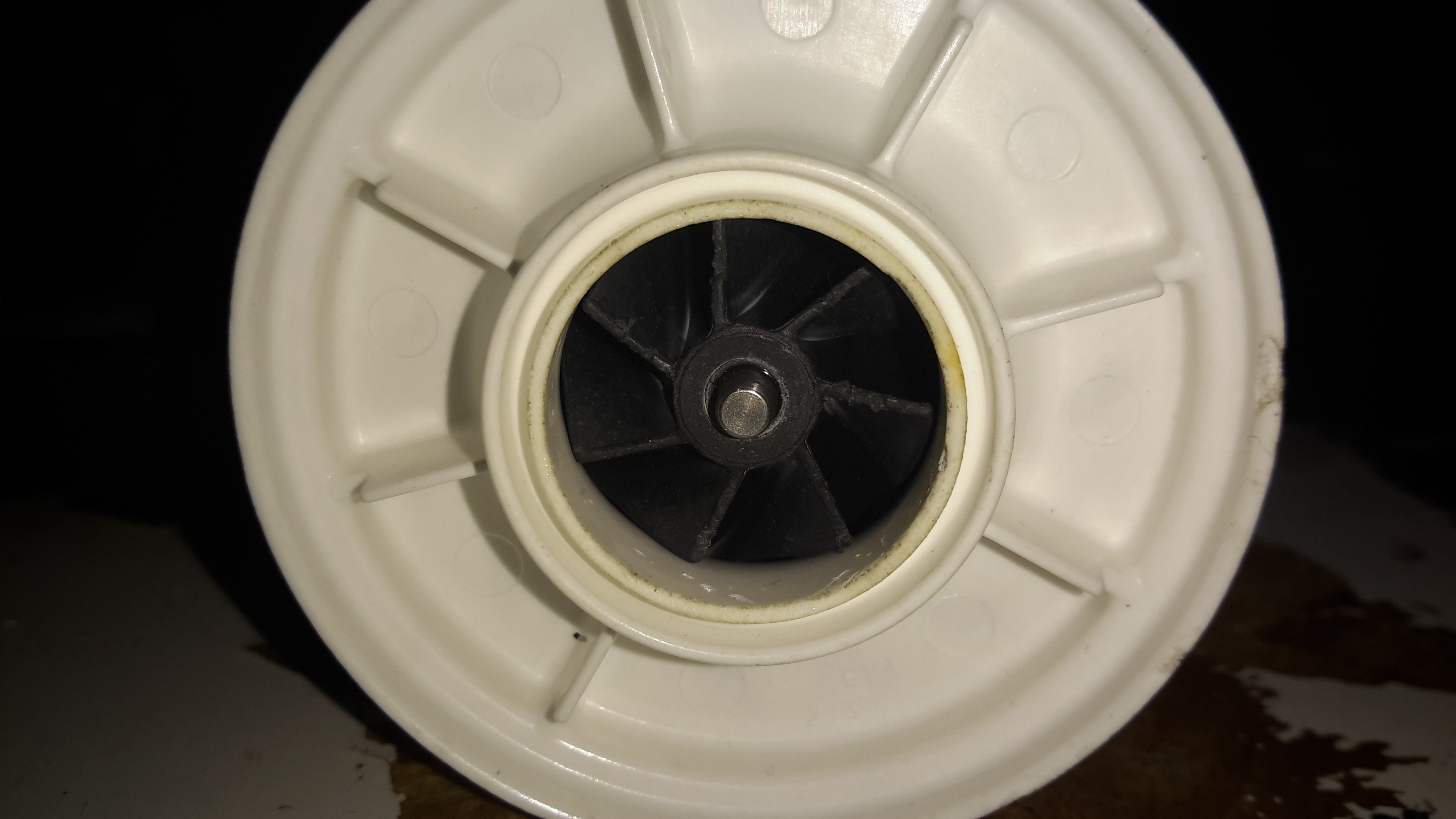
The impeller is just a centrifugal compressor wheel, identical to what’s used in engine turbochargers.
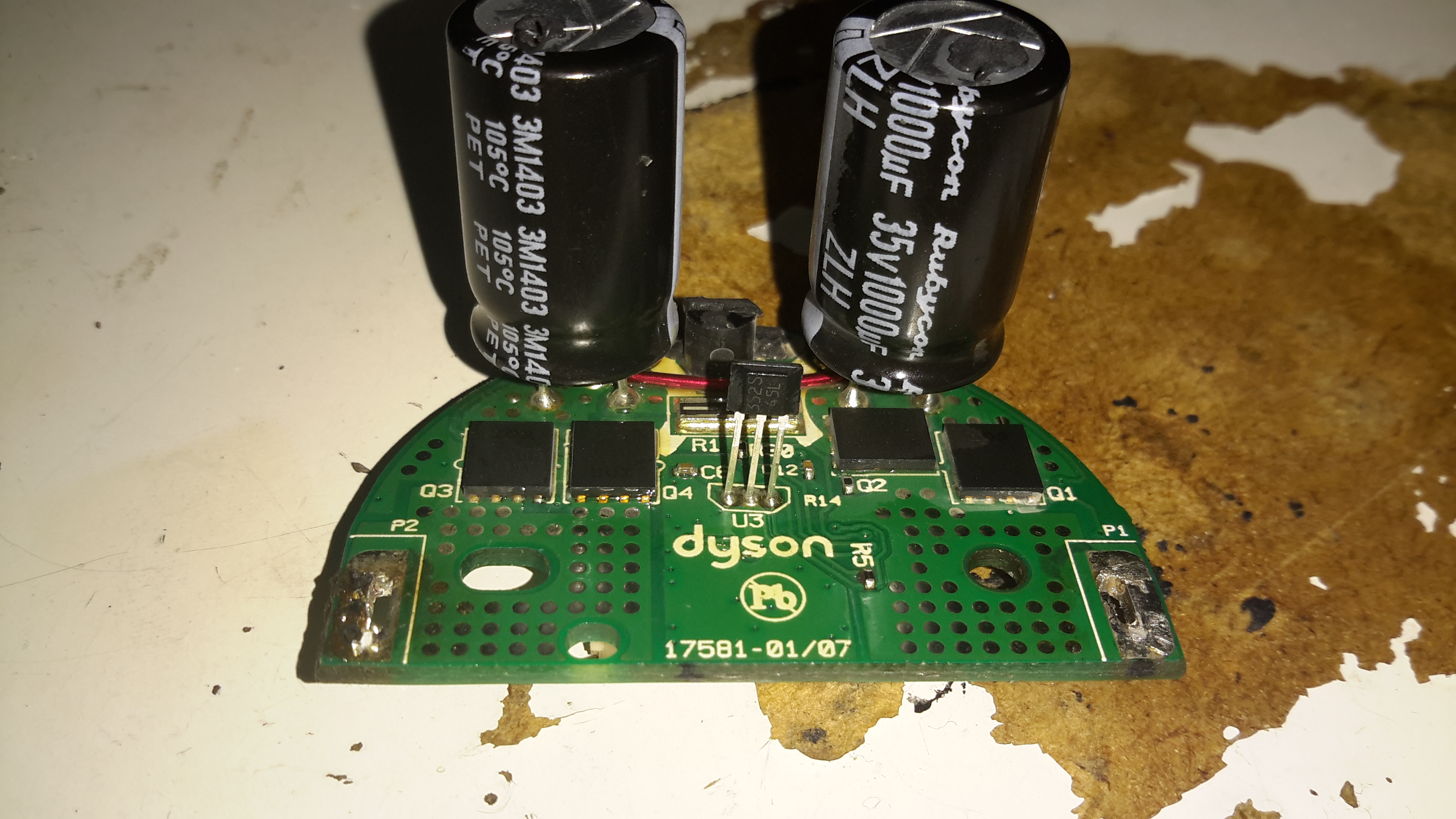
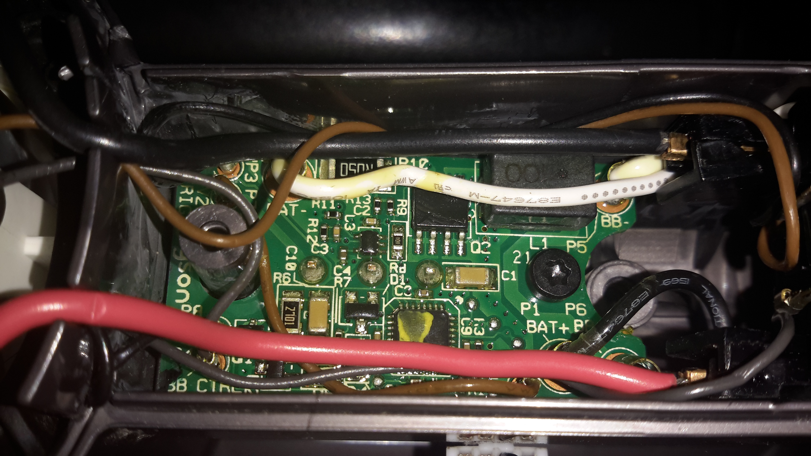
The inside face of the control PCB holds the 4 very large MOSFETs, IRFH7932PbF from International Rectifier. These are rated at 30v 20A a piece, and are probably wired in a H-Bridge. There’s a bipolar Hall switch to sense rotor position & rotation speed, and an enormous pair of capacitors on the main power bus.
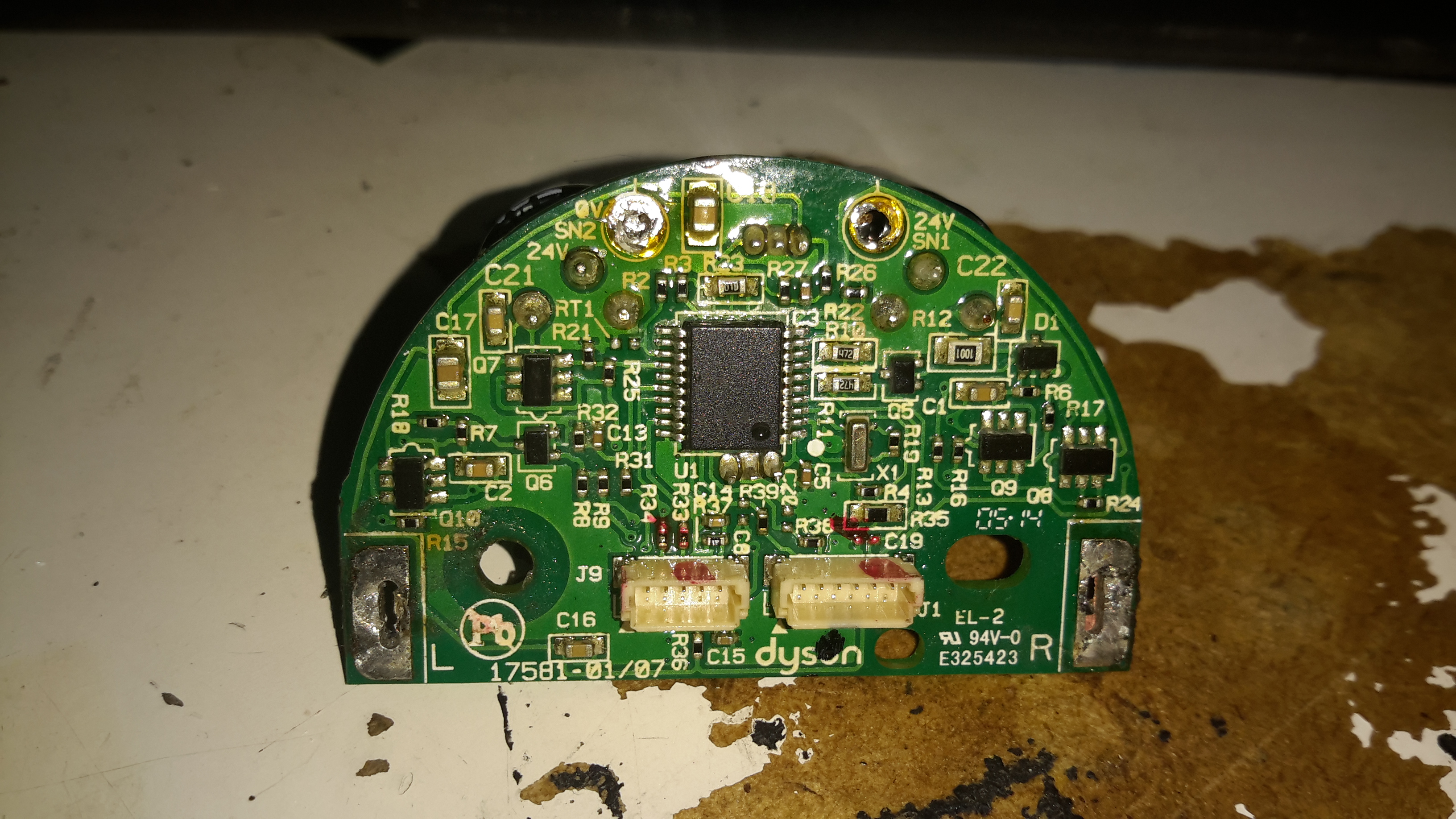
Not much on the other side of the PCB other than the microcontroller and associated gate drive stuff for the FETs.
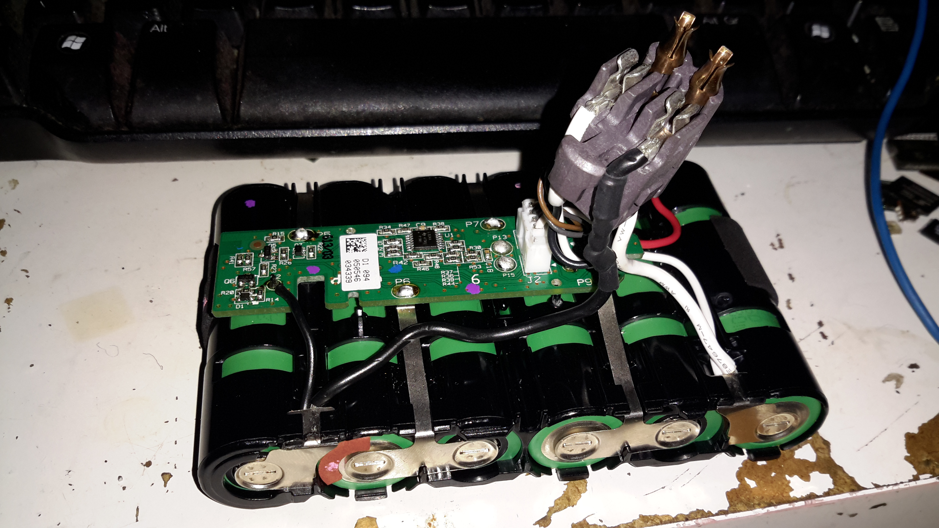
The battery pack is similar to the DC16 in it’s construction, a heavily clipped together plastic casing holding 6 lithium cells. In this one though there’s a full battery management system. The IC on the top of the board above is a quad Op-Amp, probably for measuring cell voltages.
The other side of the BMS board is packed with components. I wasn’t able to identify the QFN IC here, as it’s got a custom part number, but it’s most definitely communicating with the main motor MCU via I²C over the two small terminals on the battery connector.

Any chance you opened up the black wire from the battery pack going into the top of the terminal posts? Specifically on the terminal part side the wire has heat shrink tubing protecting a micro thermal fuse–i was hoping you could inform me of the exact part/type of fuse that is-i believe it’s a 15 amp fuse but can’t remember and I need to order this part to complete my battery pack capacity enlargement project. The 18650″s that Dyson uses are a meager 1300mAH! I’ve replaced those dead batteries with six new Samsung 18650’s that are 2600mAH and fit perfectly into the Dyson battery sled. This upgrade should double the run time of my Dyson! Again, if you have the info about that micro thermal fuse hidden with the shrink tube, is be grateful if you could provide it! Thanks!
Hi Robert,
I don’t remember pulling the heatshrink tubing off that wire & I don’t know the rating of that thermal fuse, sorry. The fact that Dyson used smaller capacity cells is because there are two types – one optimised for capacity, and the other optimised for output current. The gap between the two seems to be shrinking these days though as battery tech matures more. I doubt the Dyson pulls excessive amperage though, so the Samsung upgrade should work fine, as long as those cells keep the battery controller happy! Judging by the size of the main power wiring, a standard 15A fuse should be fine in this case.
If you’ve taken any photos I’d certainly be interested in seeing your project!
de 2E0GXE
Hello, any chance you can identify the thermal cut-off switch on this PCB? I have an old Dyson DC31 but cannot find any wiring schematics.
Is the thermal cut-off done in the controller chip?
I have the dreaded intermittent power off problem and I have tried all the tricks listed on the Internet to get around this problem. Nothing works.
I has to be the bloody cut-off switch methinks…
Thanks very much for any information.
The only thermal device I could find in this hoover is in the battery management – and this looks like a standard thermistor. I don’t still have the PCB to measure the resistance of this, but they are usually standard values. Measure the resistance at about room temp (25°C), Google will give some tables for Thermistor resistances. Unlikely that it’s failed unless the battery has reached a rather high temperature though. There’s so much electronic authentication in these devices that give many failure points. I’d also check all solder joints on the wiring between all the PCBs.
Cheers,
de 2E0GXE
Dyson publishes this:
“Most Dyson vacuums have a built in safety system that stops the machine if it begins to overheat.”
After spending an eternity with Dyson Customer Service, the only conclusion they could reach was the thermal cut-out was “worn out/weakened”. Really?
I can’t see anything on the main PCB that looks like a thermistor/thermal fuse. This circuit should be around the motor, no? There looks like a surface mount resistor labelled “R0005” on the underside of the board…could this be part of cut-out?
Thanks very much.
If that R0005 is printed on the resistor itself, this is a current sensing shunt of very low resistance (0.0005Ω). This won’t be part of any thermal cutout circuit, but it will let the system microcontroller know if the motor is overloaded, shutting the vacuum down.
The only thermal sensors I’ve found in both Dysons I’ve disassembled have been inside the battery packs. The motors are usually very well cooled by the airflow generated to operate the vacuum, so a thermal cutout wouldn’t usually be needed around there.
Thanks de 2E0GXE…
Your comment about airflow around the motor when the unit is running is really true.
So what is Dyson’s overheating cut-off then?
Sounds more complicated than just a thermal fuse. If the system does get overloaded where/how is the protection implemented? I would not expect the battery pack to get overheated so why do they have thermal protection there?
Your help is greatly appreciated. I would just replace the bugger is it didn’t cost so much.
de 2E0GXE, sorry the SMD resistor is labeled “R005” not “R0005”. The lettering is far too small for my aging eyes…
Can I bypass this easily for testing?
Thanks again.
R005 would be 0.005Ω, it should read a dead short on a standard multimeter, bypassing would only work with an equivalent resistor – a bit of wire would have a different resistance & would throw off the calibration of the current sensor. I’ve not known these to drift either, unless they’ve been overheated in the past, which would be obvious from the PCB discolouring. The battery packs have a thermal sensor as a runaway protection, these vacuums pull quite a few amps & are rather hard on batteries. Also, as the cells in the battery pack age, their internal resistance rises, so the current draw from the motor might be heating the pack up to the temperature that triggers the system. Temperature of the pack will likely be constantly monitored to prevent a fire occurring during both use & charge.
Hi,
Already made a home made driver …?
Unfortunately no, recreating a motor driver for this reluctance motor would not be trivial.
de 2E0GXE
Greetings
I’m having the dreaded “unit shuts down after 1 min” issue. I was wondering if maybe just replacing the motor control board would fix the issue? Also, I’ve had no luck locating a replacement MCB! Lol.
Any ideas?
Cheers
Marcus
Hi Marcus,
I’ve not seen this problem myself, (just did a teardown on an old one, don’t use them myself). My guess would be the batteries are wearing out. With the large current draw from the motor, it wouldn’t take long for worn cells with high internal resistance to drop their voltage below the safety cutoff point.
The battery life per charge cycle in these vacuums is terrible at best, the high power draw is very hard on the cells.
I’d definitely look at measuring the battery voltage while the unit operates, to see if that’s the problem. I doubt you’ll find any internal components as spares – you’d have to pull parts from another working vacuum, they’re pretty cheap on eBay these days anyway.
Ive repacked 3x dyson dc35 batteries with samsung 2600l 2800 2200ma cells and had no sucess .on first rebuild charger would act normal on first charge ..light went out when fully charged but on second charge charger just flashed battery didnt charge.on the next 2 attempts both batteries didnt charge charger just flashed..i tested charger with a good original battery after and was fine.i used 3 different circuit boards on the 3 rebuilds.i made sure thermistor was fine when pulled from old battery pack..im stumped to know whats wrong ..im thinking the boards need reseting as ive heard some drill batteries have the same problem ..
It wouldn’t surprise me if Dyson prevented the replacement of cells in the pack without some software magic to reset the battery management, it may be keeping an eye on the mAh capacity of the cells, and gets confused when that capacity suddenly increases with new cells.
So I have a D.C. 35 mutifloor that has the intermittent run problem I’m new to this electronic thing but I tinker and research to repair things .. what about bad capacitors? any info on this would be appreciated
Hi Michael,
You’d need an ESR tester to properly test the eletrolytics, and they would need to be desoldered before testing to get an accurate reading. Bad caps can occasionally bulge or burst at the top. I’ve not seen one with this fault though. The only large electrolytic caps are on the motor controller on the main DC bus. Testing for ripple with a scope on the main battery feed to the motor should give a fairly good idea of the condition of those caps.
Thanks for reading
de 2E0GXE
I’m looking to get a powered brush attachment for a DC35 to work on another vacuum using a voltage regulator that I have in my shop to buck a 16Volt battery pack down to the proper voltage and amperage for the powered brush attachment. Does anyone know how much power comes off the DC-DC Trigger PCB to make the powered brush attachments spin?
It’s just a simple DC motor. Use the voltage on the brushbar unit, otherwise open it up and check the specs on the DC motor.
Note, if you can’t spin the bar freely by hand, then you may have hair clogging it up. Disassemble and refurbish fully, and check the bearings. The motors aren’t strong enough to overpower the resistance of a stiff/stuck bar.
Hi, i have a problem with my DC35. I’ve replaced the batteries but the its not working. I suspect its the 3 pins that is the problem. Is there anyway to fix or bypass these three pins?
Sincere Jonas
Hi Jonas,
There is no way I know of to bypass the protections on the battery pack. The microcontroller on the vacuum communicates with the battery in operation.
de 2E0GXE
Thanks for replying. Damn i want i to work so bad 😛 It worked after i swapped the first set of 18650. But after a full charge and another change of 18650’s, (cuz higher capacity) it wont turn on at all…
Hey, so I found one of these vacuums at a thrift store and decided to disassemble it. I’m new to electrical engineering and was wondering if it’d be possible to control it with rc components? All I know is that it runs on 22v and it’s brushless.
Hi Prem,
I’m not aware of any way to control the motor used with another controller – it’s a two-phase switched reluctance motor as far as I know, and the speeds involved would require a very high switching rate on the stator winding. Do let me know if you come up with anything though 🙂
de 2E0GXE
can you see help me what is Q7, Q8, Q9, Q10 name.
Thank you!
CY- , the dash is on the top and been bit difficult to figure out what it is, I have two DC44 and both have exactly same circuit and Q9 is getting really hot on both when insert the battery, they have waxed all the components, I have the microscope and took some time to clean then found this marking for this SMD.
I have a fault where the power to the motor head is always on. Any thoughts?
Hi Pete,
I would look for the MOSFET that switches on the powerhead, checking that for shorts. Barring that, there’s a possibility of a short somewhere in the internal wiring, or even a fault that’s keeping the MOSFET driver switched on constantly, including a microcontroller fault. Nevertheless, there is going to be some tracing out of PCBs & internal wiring.
Cheers
hi, Pete, & the engineer,
I have the same problem. I buy the fault on eBay and try to study the design. Great thank you for all the contributors and “The great engineer”.
Q8 in the motorhead is really hot and as soon as insert the battery. I have applied isopropyl alcohol, evaporate so quickly. When I Scarpe the component and found the markings is CY- (- in superscript) but could not identify the right component. Please let me know if you have any clue.
When I opened it, the SMD CY- closer to the air intake and saw some dried watermarks. May have the water damage. I have two DC44 both have the same problem. If I could locate the CY- smd I would buy the MOSFET and CY- and try, as I appreciate the design and proud of the British design, don’t like the attitude towards the customer. The man owns more lands in the UK next to the queen. I have an old friend who gave up electronics after over 50 years of service gave me the inspiration and said these guys are smart using an old video cassette player’s head spinning technology. Making millions using Patented technology from others.
Hi, Raj did you solve issue with your vacuum or identified name of the mosfet driver ? I have the same problem in my dyson DC31.
Thanks
Hi Raj, Kamil,
Those MOSFETs likely form a H-Bridge for driving the motor windings – so it should be pretty easy to work out which type of FET it is (N or P), by metering out the connections to the power rails & windings. Compare to standard H-Bridge circuits for clarification. It appears to be a SOT-23-6 package, there are lots of those about so you should be able to find a suitable replacement, if not the exact one.
Hi, my DC31 was working perfectly until I cleaned it out with compressed air ♂️, battery is ok and trigger micro switch tests out fine. No signs of visible component damage, any ideas? (Apart from don’t use compressed air)
Hi Royster,
I honestly wouldn’t have thought that compressed air would cause any damage to a DC31 – all the boards are heavily conformal coated, so component damage is unlikely. (Unless the compressed air was at 300 bar direct from a diving cylinder! ;)). I suppose it’s possible that one of the wiring looms inside the unit has been damaged, I’d check each core of the loom wiring to make sure there’s continuity. Other than that I can’t think of anything else.
Cheers
Thanks, I’ll check them all out. Like you say it must be something simple.
Merry Xmas and Happy New Year to all
Sorry , I have been decorating the house and full of mess and didn’t have the time to spend on Dyson. Now back to the reverse engineering. About to order CY – (dash is super script). From s-manual web site which is very realizable for identify the SMD I have worked out CY, could be comparator and while checking the data sheet it be used as square wave oscillator. i have checked dimensions manually and conclude it is SOT 25, and (LMV331W5-7 DiodesZetex, Comparator, Open Collector O/P, 2.7 → 5.5 V 5-Pin SOT-2) , which I have the information from RS also could purchase from different places.
Please if anyone come across any more information let me know if it could be a different component.
All the Dyson I have this component get extremely hot as soon as insert the battery, as discussed before the MOSFET could be shorted and also about to purchase the above mentioned IRFH7932PbF. I also repair SMPS, and MOSFET also a big culprit and poor fellow in the circuit to get the bad hit. I haven’t check the MOSFET physically and according to the engineer’s advice about to place the order.
This Dyson made me to follow Power Electronics and micro controller courses on you tube to understand further. I have found 2 good courses on power electronics and if anyone knows about micro controller please let me know.
Have a great holidays and bright prosperous new year. A special thank you for the engineer to keep this page alive
http://www.s-manuals.com/smd/cy
Hi, don’t suppose you ever made a controller for the motor? I’d like to use the motor in a project to blow air, I’ve had it running out of the housing with original gubbins but I’d like to have it switch on via a relay
Hi Ben,
Unfortunately not, I’m no expert in brushless motor drive building. I suspect it would take some considerable work!
No worries, thanks for the reply
I was trying to clean the 3 pin battery contacts inside the vacuum handle but accidentally touched the two big prongs and a spark flew… Can this be fixed? How…?
Hi Roberto,
If you mean the actual vacuum contacts, and not the battery pack contacts, I wouldn’t have thought that shorting them momentarily would have done any damage – this was likely just the filter electrolytics on the electronics discharging. There may also be a fuse internal to the vacuum that has blown. This should be simply replaced.
However if you mean the battery contacts, there may be a fuse in the battery pack that has cut the output – be it electronic or a good old fashioned bit of thin wire. If it’s electronic, applying charging voltage to the pack directly may reset the protection circuitry & revive it. If this doesn’t work the fuse is either mechanical or the pack is damaged.
Cheers
I had this kind of short but with 2 of the 3 littles pins that are supposed to make contact with the battery. There was a small spark… after that there was no light or any sign of activity with the vacuum… it’s completely dead…
Any idea of what should I checked ?
Regard’s
Made this mistake too, luckily with no damage and my dc35 still runs perfect. The motor’s pcb x2 capacitors are still full while the battery is off, so shorting something inline with that source will cause sparks and possible damage.
I would like to ask.. I check the Motor Control Board Reverse R17 parts. Sparks come out. How much resistance should I change?
Hi jjw,
Unfortunately I have no idea what value R17 is.
Hi, can you identify which MCU is used in the motor driving circuit?
Hi. I was trying to clean the 3 pins in the handle an I accidentally shorted pin 2-3 and the were a long spark… after I put back the battery, there was no activity at all with the vacuum ! Do you have any idea of what could be the problem ?
Regard’s
Hi, I was wondering if somehow we could bypass the battery and use a 24v 10a power supply instead.. Is it possible? Thanks!
Hi Audy,
As far as I know, there is direct communications with the battery, and if that comm link fails, the unit will stop working!
Can u short the Dyson DC35 battery pack’s thermal fuse? I’m reading about 10K.
Hi!
Battery processor – SMD CODE: “a404 t44 20mudb 3y1836” this is the ATTINY 44-20MU package 20-QFN-EP ( https://www.components-store.com/product/Micrel-Microchip-Technology/ATTINY44-20MU.html ) .
Hi Pawel,
Thanks for that little detail! Sometimes these SMD codes can be a bit of an arse to decipher!
Cheers
I want to convert dyson dc56 from battery power to power supply. What’s the way?
The only way I could think you would be able to perform this would be to replace the cells with a voltage divider chain that fooled the battery BMS into thinking the cells were always fully charged.
Cheers
Interesting thought regarding the voltage divider, I was thinking the same. Has any one tried this yet?
Hello all,
I have tried to do it, removing battery cells and providing 8V, 16V and 22.2V on the required pins, using two DC-DC Step Down Buck Converter 3A LM2596S, but without success.
But:
1) when I have done this test I hadn’t yet understood the currents that were in play (I was trying with a MAX 5A power supply, maybe not enough for nothing?)
2) after this unsuccesfull test I have done other experiments and at the end I have burned the main controller
Hi,
I’ve managed to shear off R42 and damage R33 during disassembly. I don’t suppose you have a close up photo of the top of the BMS. Maybe one you didn’t include in article above. I can almost read it off “Battery pack opened” photo. Rather annoying, I didn’t notice until after I’d put in new batteries and it didn’t start.
regards,
aja
Hi Andrew,
Sorry I don’t have any photos clearer than the one I have here! You may be able to find one elsewhere, or one of the other commenters may be able to assist.
Cheers
Hey Andrew,
I did the same thing opening my battery. Broke R33.
R42 is still intact, the marking is 01D
There seems to be only 2 types of resistors on the board, 304 and 01D. from the tiny piece i have left of R33, i belive it’s 01D as well.
Here’s a closeup.
https://imgur.com/yQfEw7w
Hi Igor,
Thanks for chipping in with this info! The EIA-96 code “01D” translates to 100kΩ.
Cheers
So interesting thing that happend for me is that the vacuum stopped working completely after i have taken the battery apart.
The only sign of life I can get from it is the short blink of MAX button if MAX is on and i press the trigger. motor doesn’t start.
I understand this is to do with controller on the battery not being happy? do you you think that resistor I smashed opening the pack could do this?
Hi Igor,
Thank you very much for that, I may just give it a go with both being 100k and watch to make sure it doesn’t do anything silly. This might take a while as I’m moving apartment.
Sorry for the late reply, I didn’t see it.
Great site, very informative.
I have a DC35 (I think about 9+ years old) which was cutting out every few seconds with a flashing light on the motor/trigger unit. I did all the checks advised, I decided to remove the battery to check the off load voltage (was about 24v), however when I reconnected the battery the unit failed to run at all.
I then bought a replacement battery, charged it and tested the unit, but again it refused to run.
I opened the motor unit and handle, checking for broken wiring, interesting to find that the filter microswitch had both wires soldered together on one terminal (so not in use).
Could there be some inbuilt timer for the battery, or might sense that a non-original battery has been fitted?
My fix was to buy a new ( old stock) motor/trigger unit and the new battery, all working fine for me now, total cost 90 GBP, at least 1/3 cheaper than a new model.
I’m interested in your situation as it matches mine. I inherited a DC34 and it worked pretty well apart from short battery life. I priced up an original battery and rejected that, buying an Amazon one (branded Aryee, whatever that is). It worked fine and so I decided to buy a second battery of the same make. On plugging it in, the vacuum died completely and has not worked since.
I bought a second body and that is also dead (using my batteries), so I suspect that somehow the battery communicates with the vacuum and says it has been tampered with, disabling both parts and anything that gets plugged in afterwards.
If that’s the case, then I’d say that’s sharp practice as even connecting the original battery back up is fruitless.
Are you able to use the new body you have with all of your previous batteries?
Hello and sorry for the delay in my reply ( I did not see your entry until today).
My DC35 is still working well. From memory I did not try the original (old) battery in the new motor/trigger unit because I did not want to risk a total shutdown again ( of the kind you appear to have suffered).
It is strange that the vacuum is designed with a removable battery, but when that battery is replaced it appears to lock the unit in an unserviceable state.
What us your current situation?
Trying g to make custom adapter for a ridgid battery as I can’t find one online. They make a falters for Dewalt, Milwaukee etc.. how do they get around battery bms?
Thanks for any information
*adapter
Also my unit is a dc35,sorry if any inconvenience
Hello all,
some one have discovered something new about control this motor without the original controller?
I see at this address there is a discussion around the same motor, the only other info I have found.
https://maker.pro/forums/threads/connect-a-2-coil-stator-to-3-phase-esc-possible.280562/
Frank
Someone already did it here for dyson v6 and v10 motors.
https://hasanunlu.github.io/2023/06/14/Motor-Controller-Software-and-Circuit-for-Dyson-Vacuum-Cleaner-Motors.html
Hello,
I have a DC35 battery not charging when connecto to charger, and I consider a fuse 15A 1206 in BMS broken but it locate in backside , so I need remove all wire from battery pack to BMS then I can see the backside board. Does the BMS will be lock if remove connection from battery cell package ?. Any way to unlock BMS DC35 if I’m not lucky ?