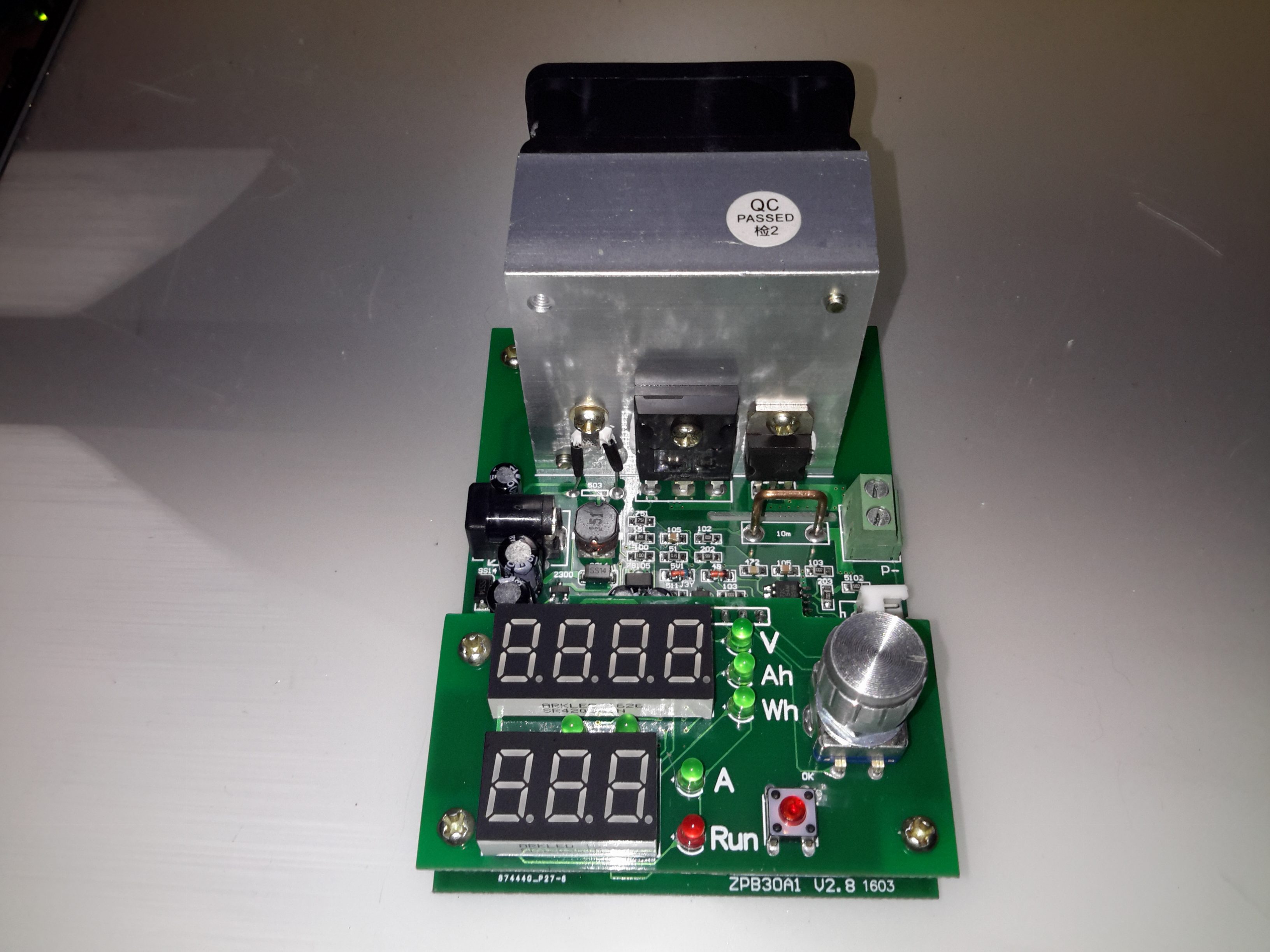
Here’s a useful tool for testing both power supplies & batteries, a dummy load. This unit is rated up to 60W, at voltages from 1v to 25v, current from 200mA to 9.99A.
This device requires a 12v DC power source separate from the load itself, to power the logic circuitry.
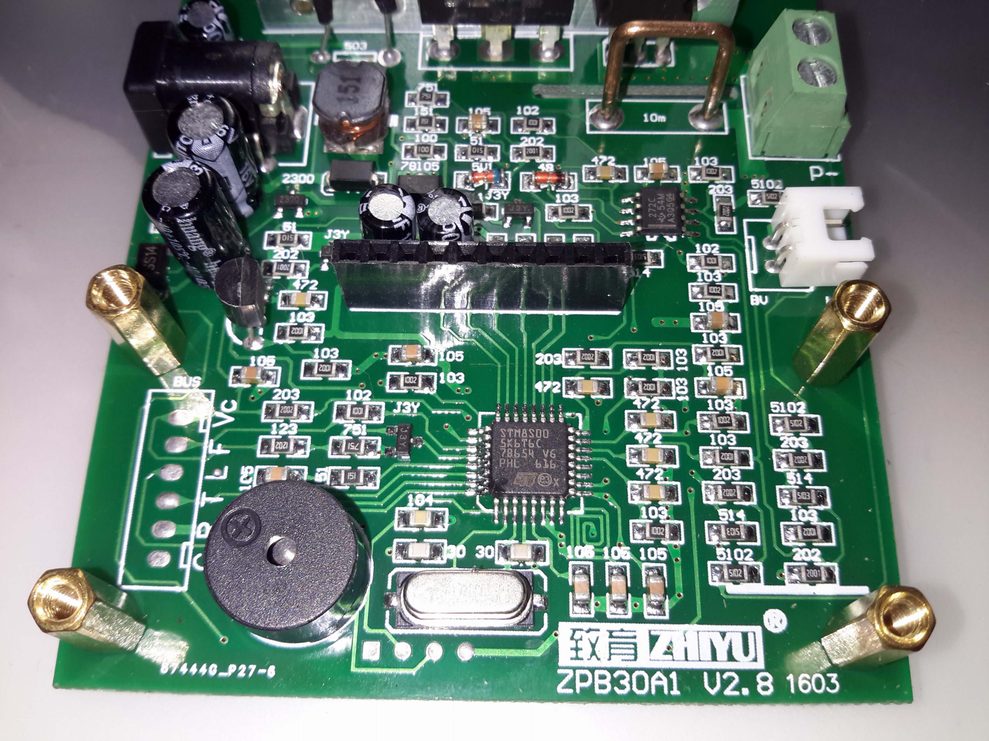
Like many of these modules, the brains of the operation is an STM8 microcontroller. There’s a header to the left with some communication pins, the T pin transmits the voltage when the unit is operating, along with the status via RS232 115200 8N1. This serial signal is only present in DC load mode, the pin is pulled low in battery test mode. The 4 pins underneath the clock crystal are the programming pins for the STM8.

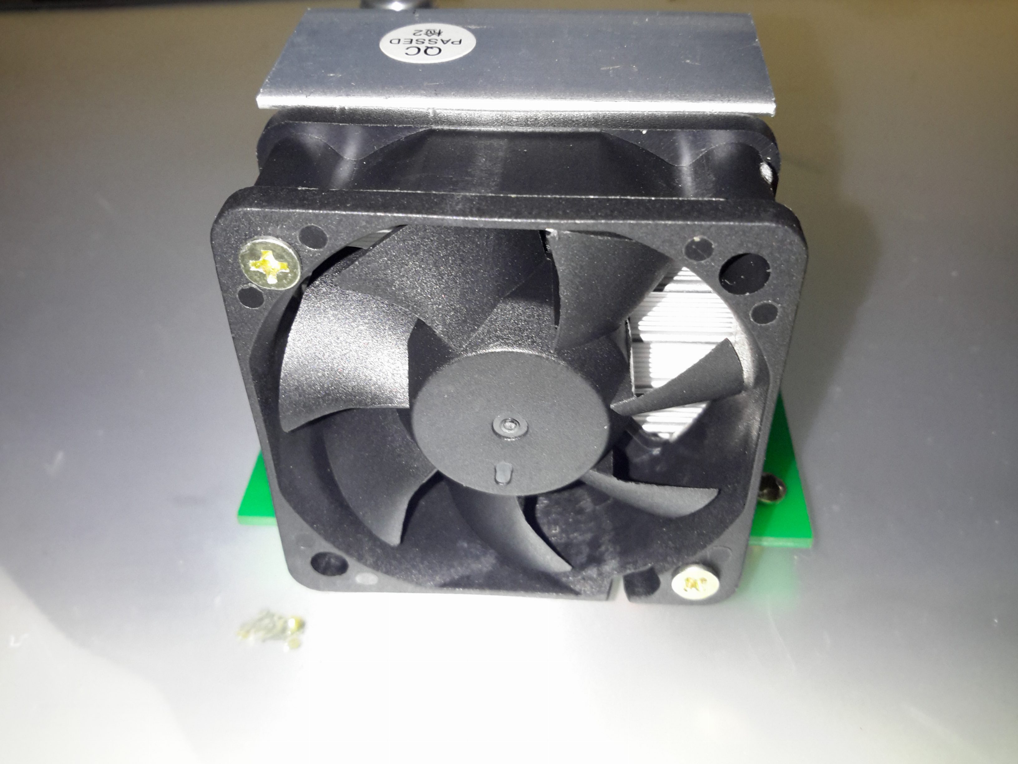
The main heatsink is fan cooled, the speed is PWM controlled via the microcontroller depending on the temperature.
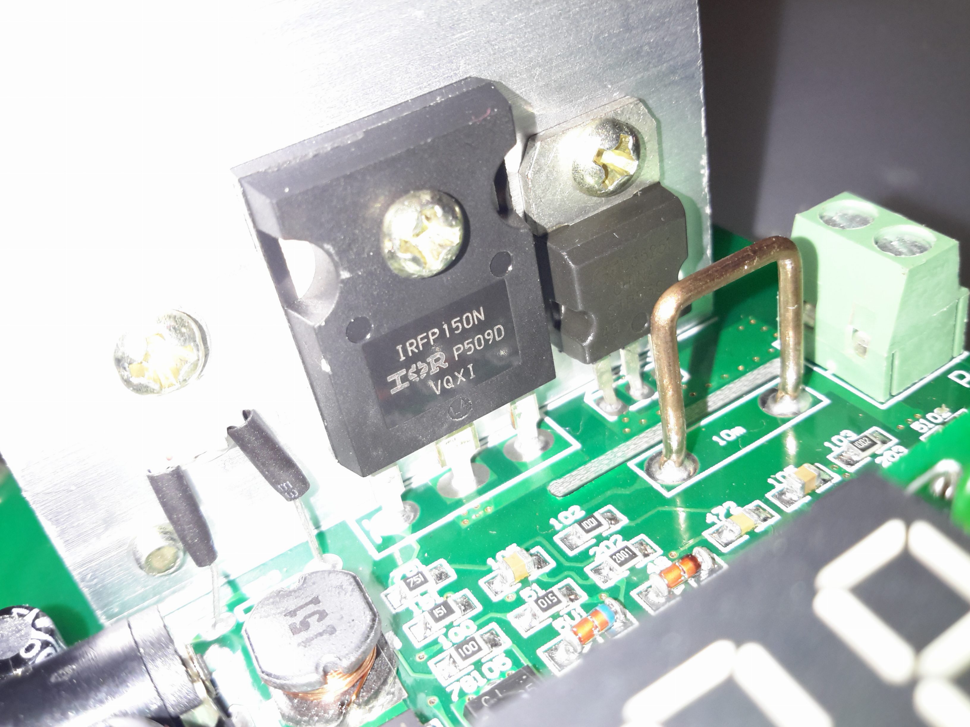
The main load MOSFET is an IRFP150N from Infineon. This device is rated at 100v 42A, with a max power dissipation of 160W. On the right is a dual diode for reverse polarity protection, this is in series with the MOSFET. On the left is the thermistor for controlling fan speed.
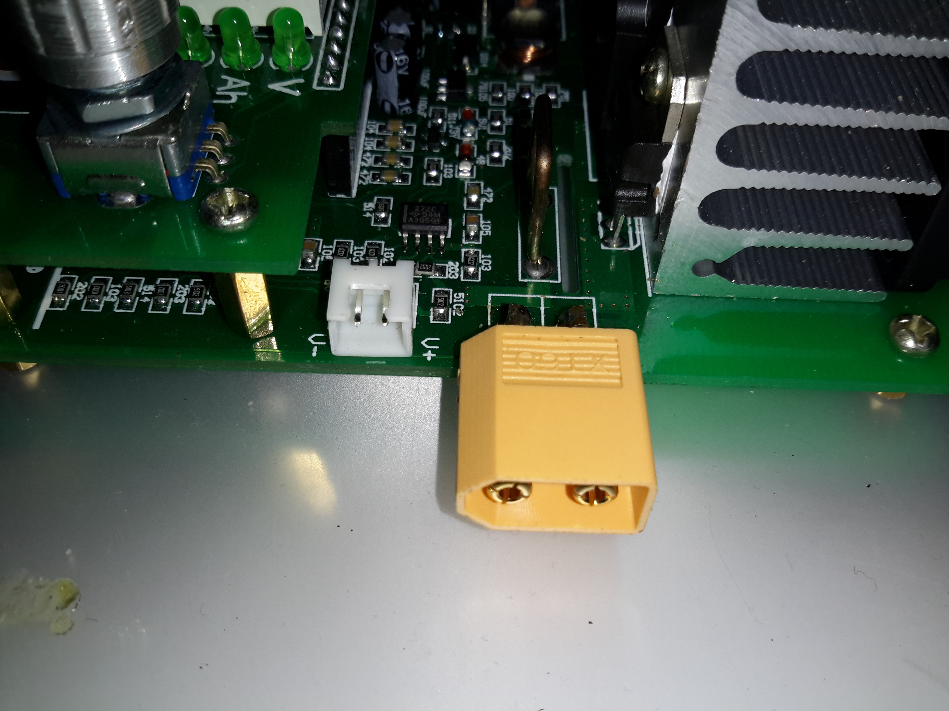
The load is usually connected via a rising clamp terminal block. I’ve replaced it with a XT60 connector in this case as all my battery holders are fitted with these. This also removes the contact resistance of more connections for an adaptor cable. The small JST XH2 connector on the left is for remote voltage sensing. This is used for 4-wire measurements.
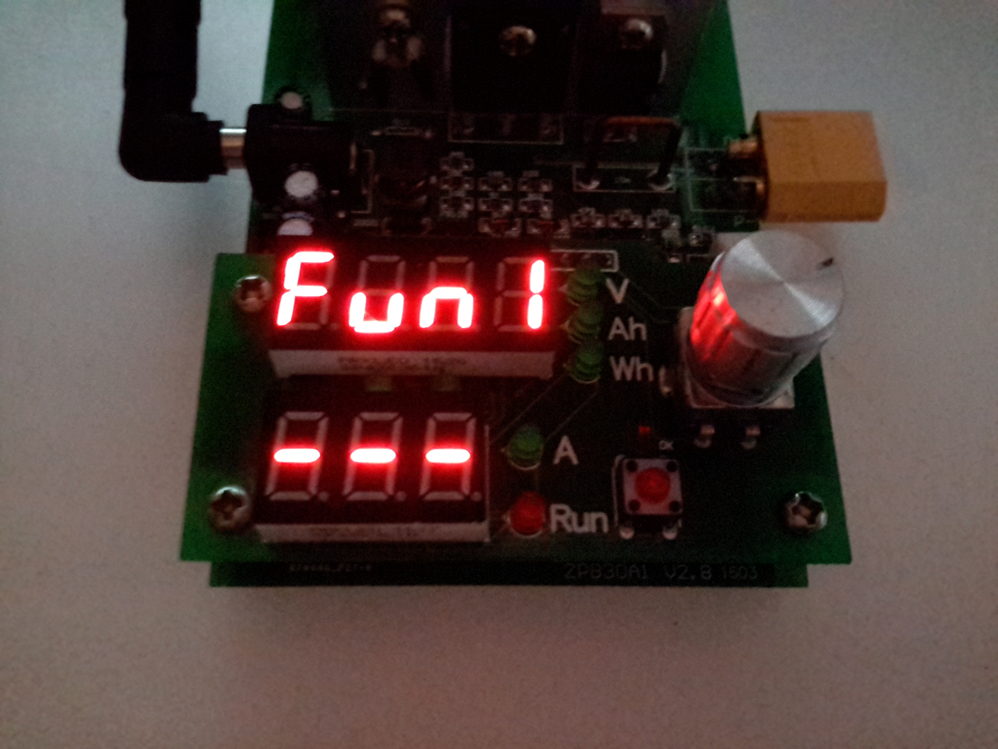
Powering the device up while holding the RUN button gets you into the menu to select the operating modes. Function 1 is simple DC load.
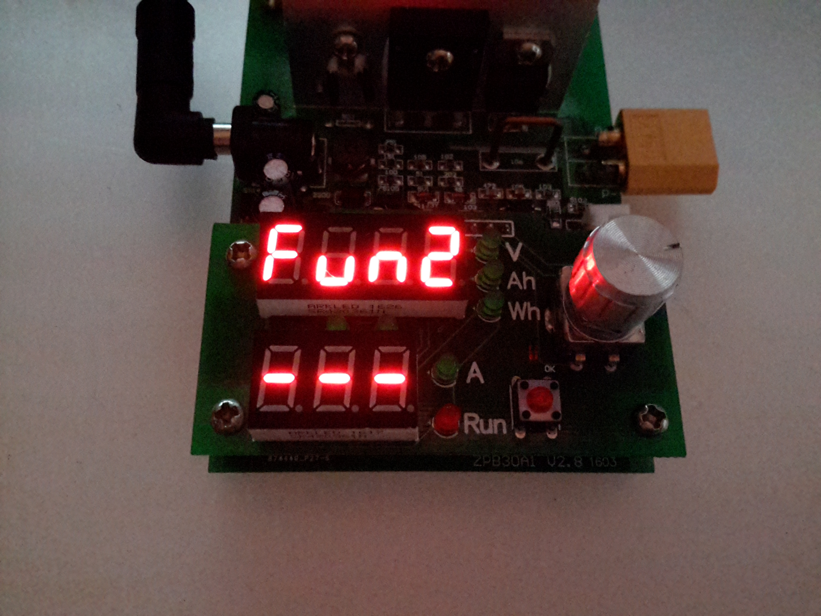
The rotary encoder is used to select the option. Function 2 is battery capacity test mode.
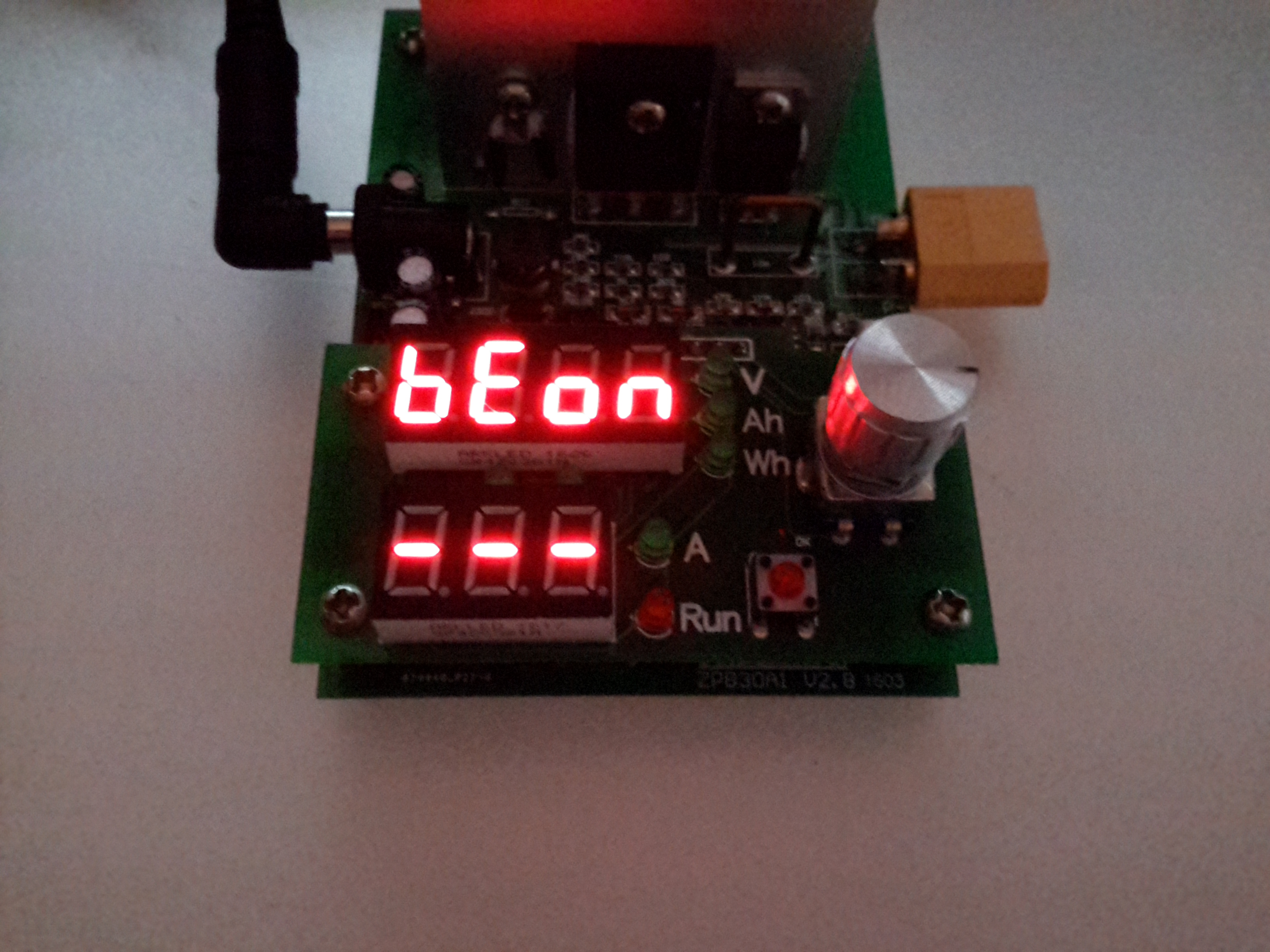
After the mode is selected, an option appears to either turn the beeper on or off.
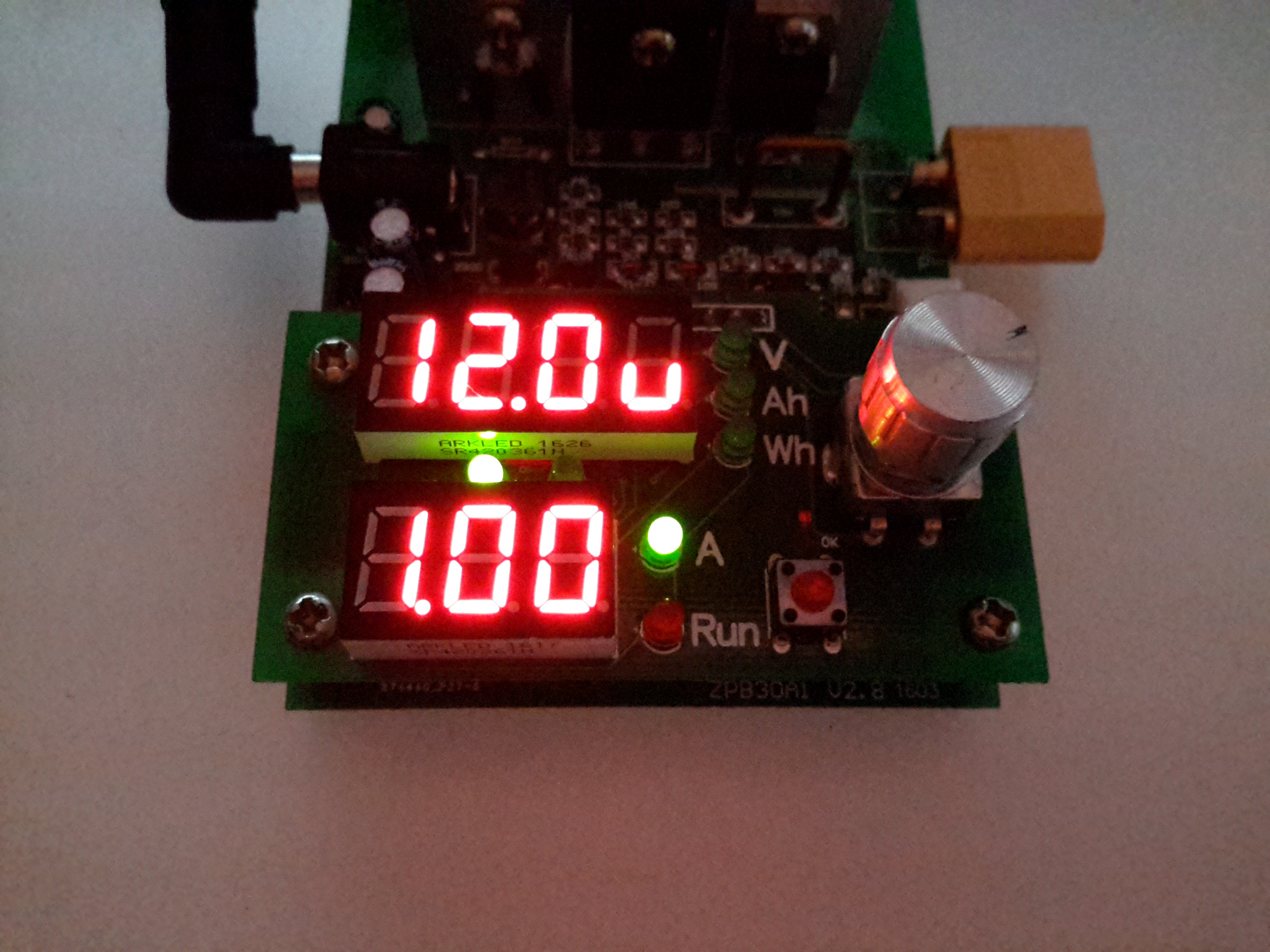
When in standby mode, the threshold voltage & the load current can be set. Here the Amps LED is lit, so the load current can be set. The pair of LEDs between the displays shows which digit will be changed. Pressing the encoder button cycles through the options.

With the Volts LED lit, the threshold voltage can be changed.
When in DC load mode (Fun1), the device will place a fixed load onto the power source until it’s manually stopped. The voltage setting in this mode is a low-voltage alarm. The current can be changed while the load is running.
When in battery discharge test mode (Fun2), the voltage set is the cutoff voltage – discharge will stop when this is reached. Like the DC load mode, the current can be changed when the load is running. After the battery has completed discharging, the capacity in Ah & Wh will be displayed on the top 7-segment. These results can be selected between with the encoder.
Below are tables with all the options for the unit, along with the error codes I’ve been able to decipher from the Chinese info available in various places online. (If anyone knows better, do let me know!).
| Option | Function |
|---|---|
| Fun1 | Basic DC Load |
| Fun 2 | Battery Capacity Test |
| BeOn | Beeper On |
| BeOf | Beeper Off |
| Error Code | Meaning | |||
|---|---|---|---|---|
| Err1 | Input Overvoltage | |||
| Err2 | Low Battery Voltage / No Battery Present / Reverse Polarity | |||
| Err3 | Battery ESR Too High / Cannot sustain selected discharge current | |||
| Err4 | General Failure | |||
| Err6 | Power Supply Voltage Too Low / Too High. Minimum 12v 0.5A. | |||
| otP | Overtemperature Protection | |||
| Ert | Temperature Sensor Failure / Temperature Too Low | |||
| ouP | Power Supply Overvoltage Protection | |||
| oPP | Load Power Protection |

Thanks for the table at the end there. My unit was giving Err6. I test the Netgear PSU (which was rated at 12v 1.0A) and found it was actually putting out nearer 16v! So Err6 may indicate an under or over voltage error.
Hi. That sounds like the old linear type PSUs – the voltage is only 12v under the rated 1A load, there’s no proper regulation. If it’s a SMPS, it’s a poorly designed or very faulty one! I’ll update the table entry to reflect the fact that overvoltage can trigger this error code 🙂
de 2E0GXE
so i have an err4 on mine what now?
I don’t have any more information on a general failure error code, but I would imagine your unit is damaged. Other Chinese sources list err4 as “circuit fault”, so something might have gone wrong with the tester circuitry / MCU itself.
de 2E0GXE
Where can I purchase the load unit?
Hi, these electronic loads are available on eBay, AliExpress, etc.
Apologies for the delay, Akismet spam binned your comment by mistake.
de 2E0GXE
Have you checked if the voltage sense lines actually do something? On the 2.7 revision they don’t have any effect
Hi,
The voltage sense terminals do work fine on the unit I have, maybe there has been a firmware update at some point that changed this?
On my 2.7 unit 4 wire connection works as expected.
thanks for this interesting review.
Did you measure the accuracy of current and voltage measurement?
Mine is 10-11% off the real current!
I bought one and the polarity of the 12V power plug isn’t documented. Is the center pin Positive?
Thanks
Hi Irv,
The power connector is indeed centre positive.