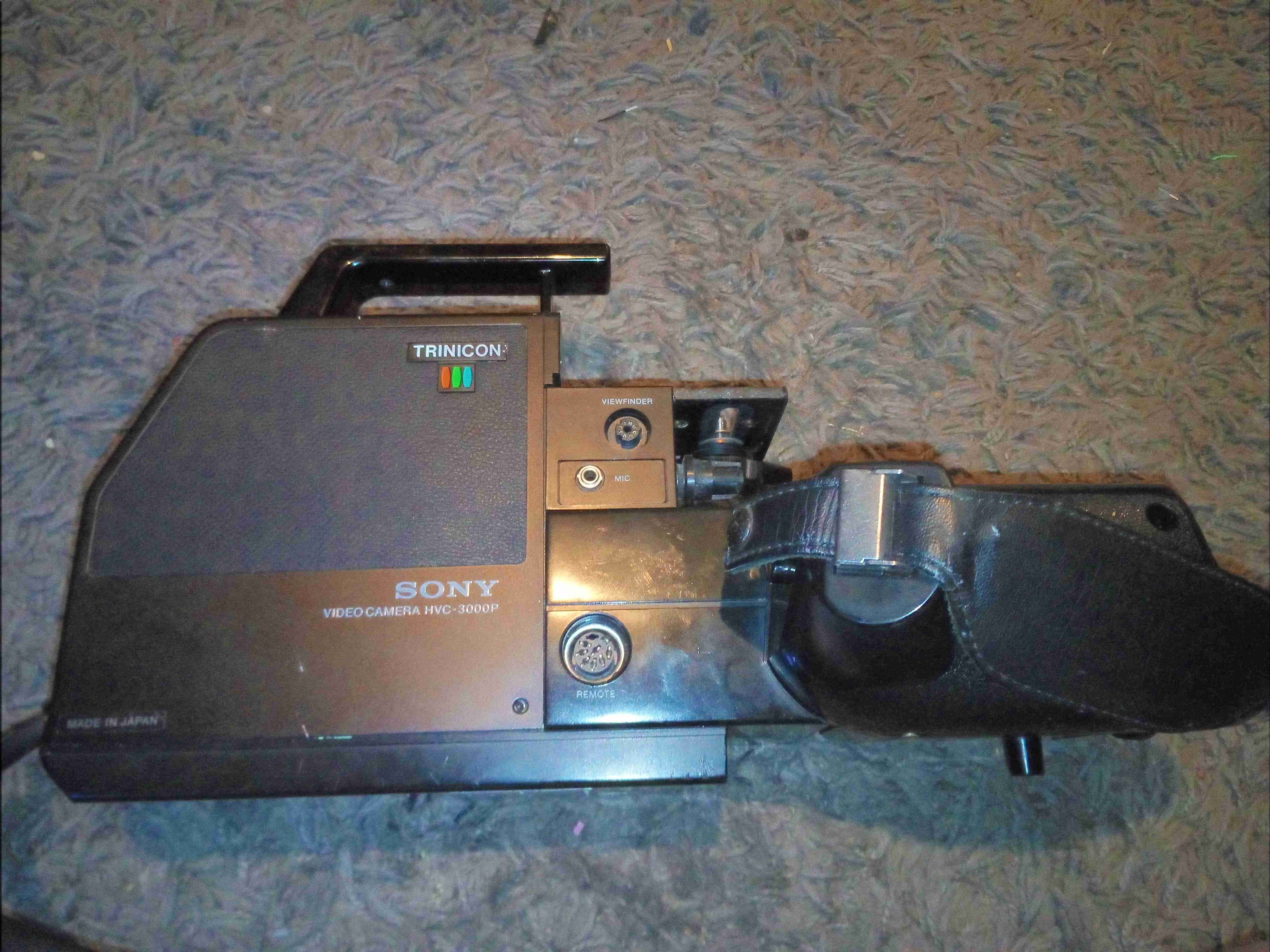
Following on from the viewfinder teardown, here’s the rest of the camera. This unit dates back to 1980, and is made almost exclusively of cast aluminium. Very little plastic has been used here & only for the bits that the user comes into contact with. This camera is based around the Sony Trinicon camera tube system, technology dating back before CCDs. There aren’t many controls on this side of the camera, only the record button, which is hidden behind the camera handgrip.
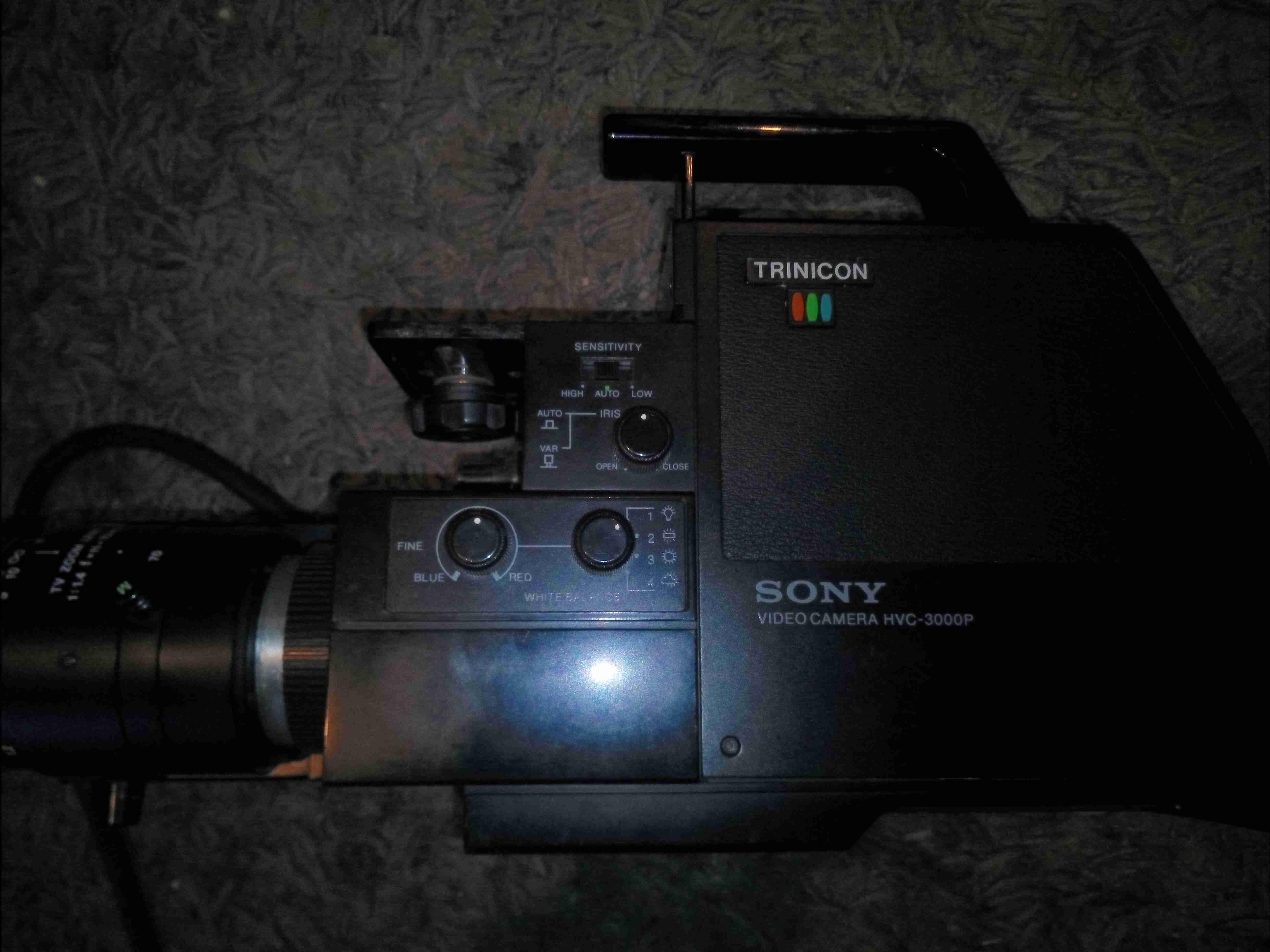
The other side of the camera has most of the controls for the picture.
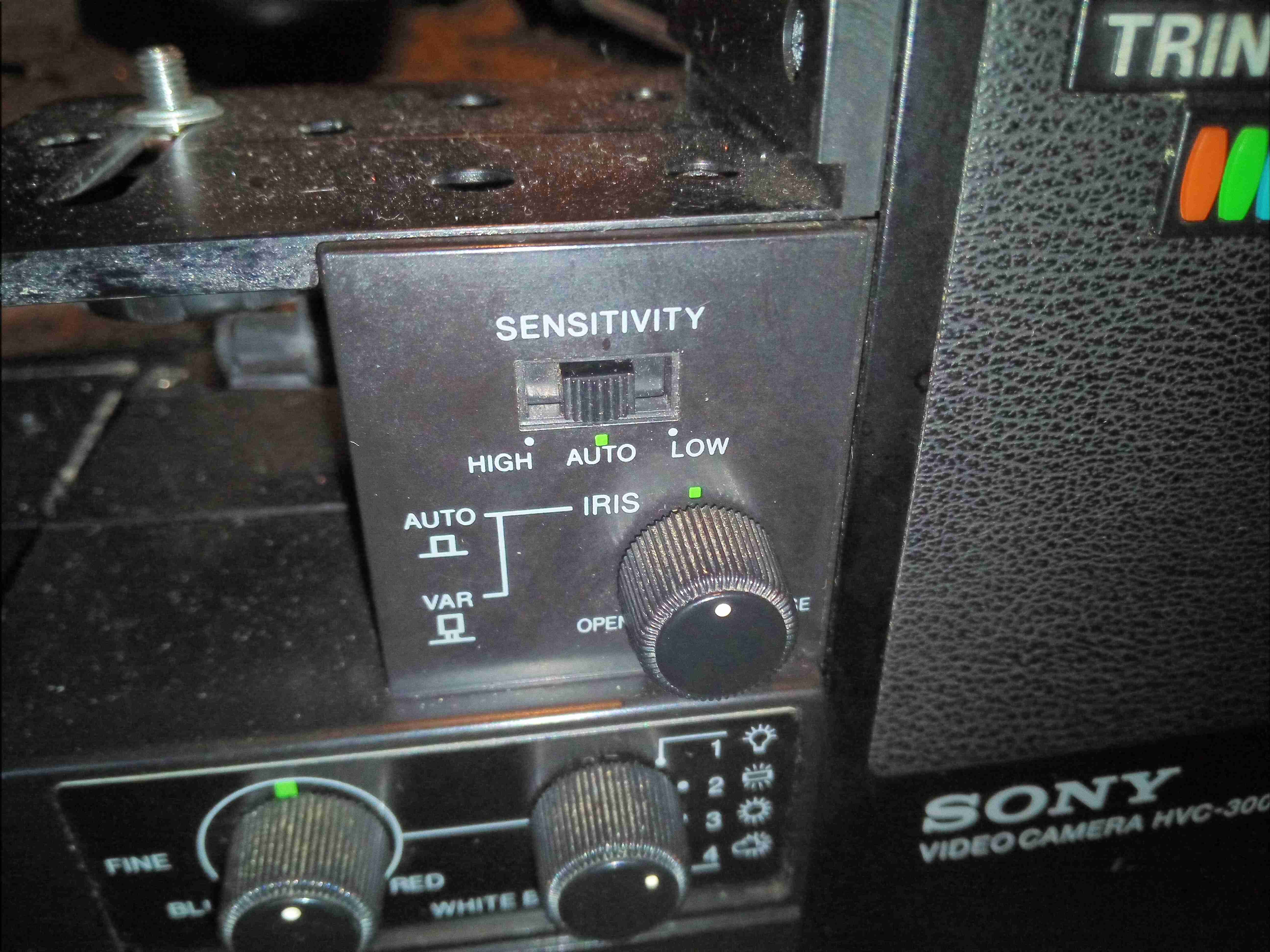
The image controls inclue auto / manual iris, white balance & colour balance.
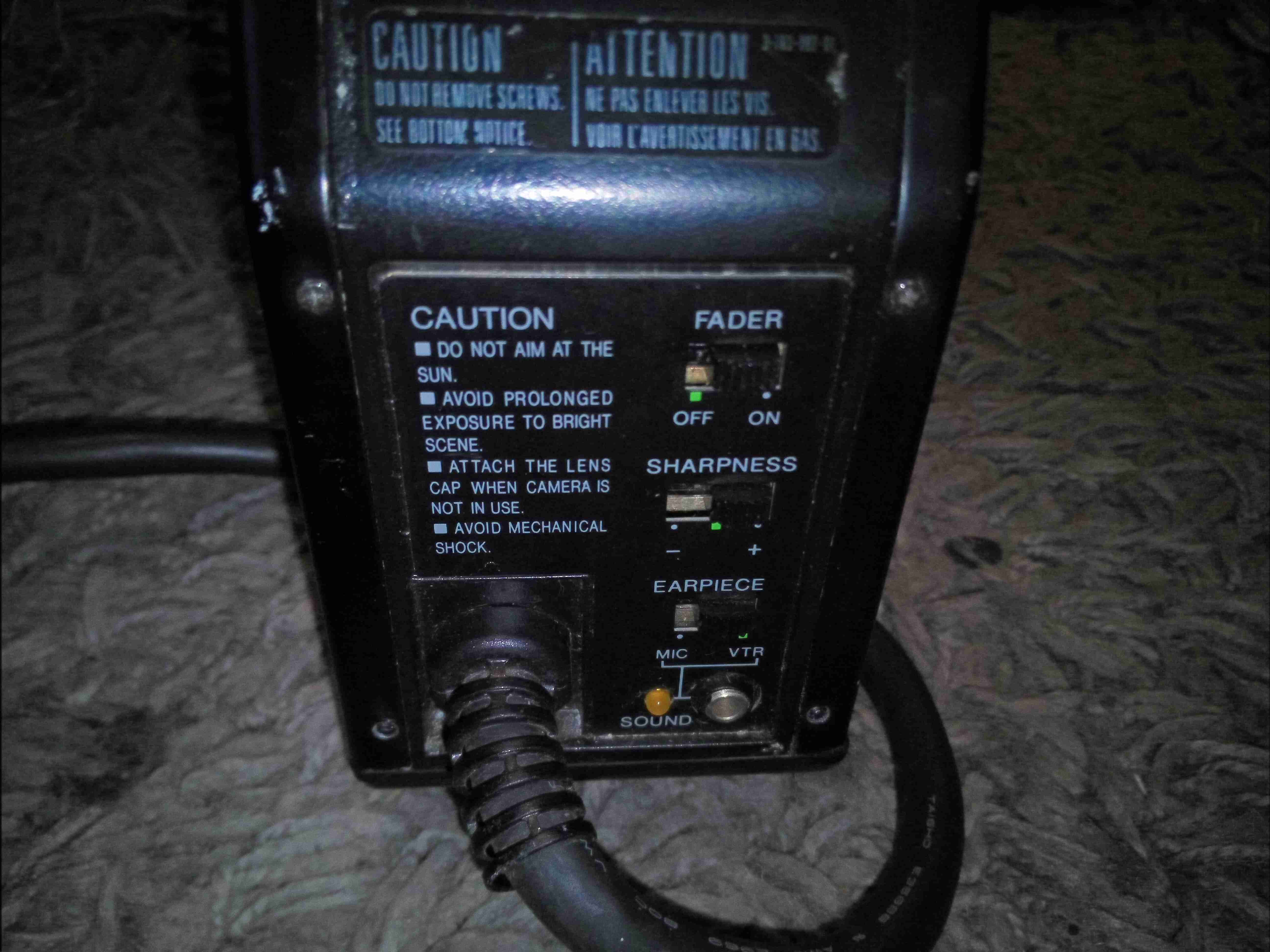
Sharpness & fader controls are on the back of the camera, along with the umbilical cable which would have connected to a Betamax recorder.
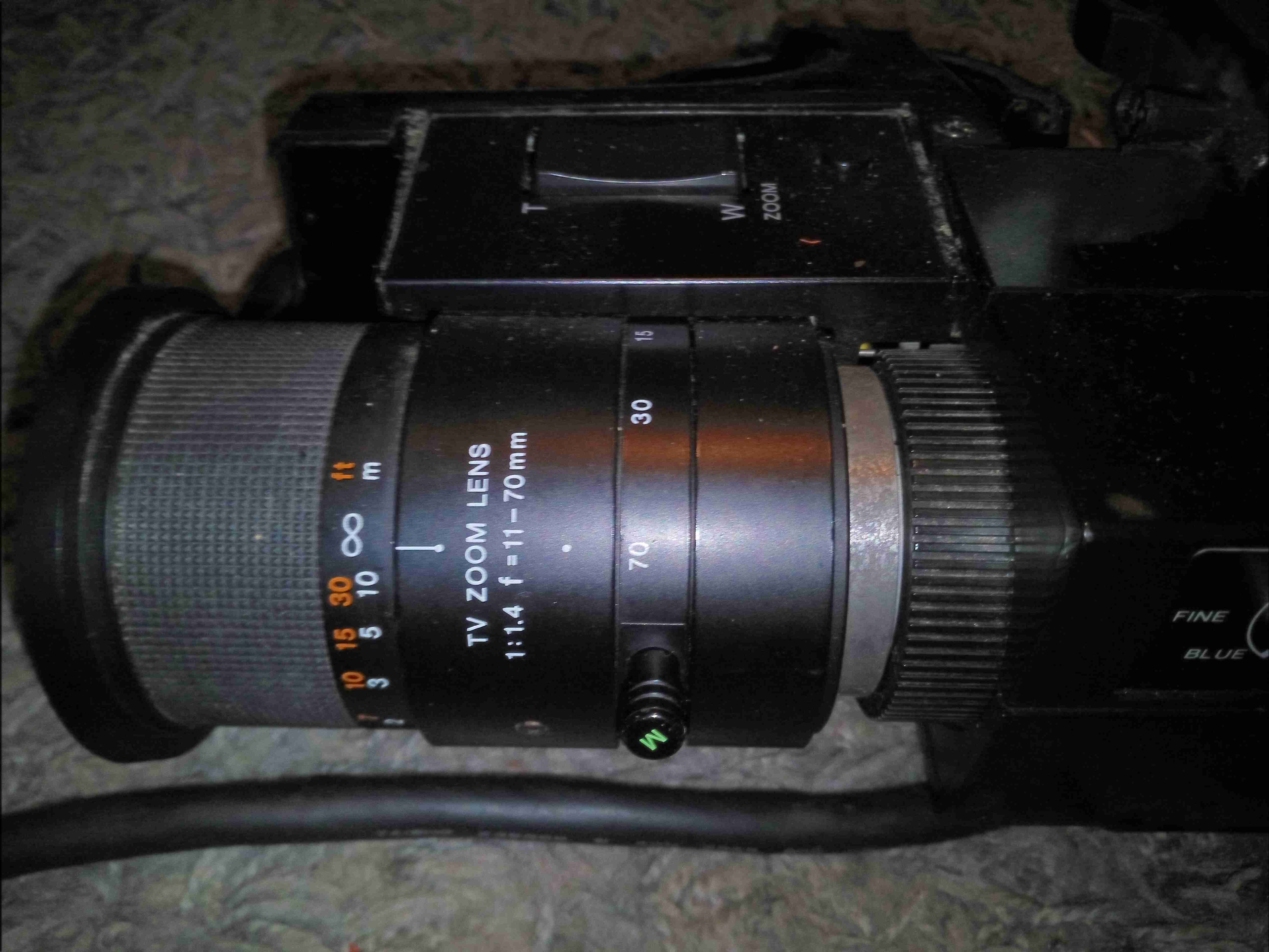
The lens on this camera is massive, at least a kilo of optical glass. Focus control is manual, with both auto & manual zoom control.
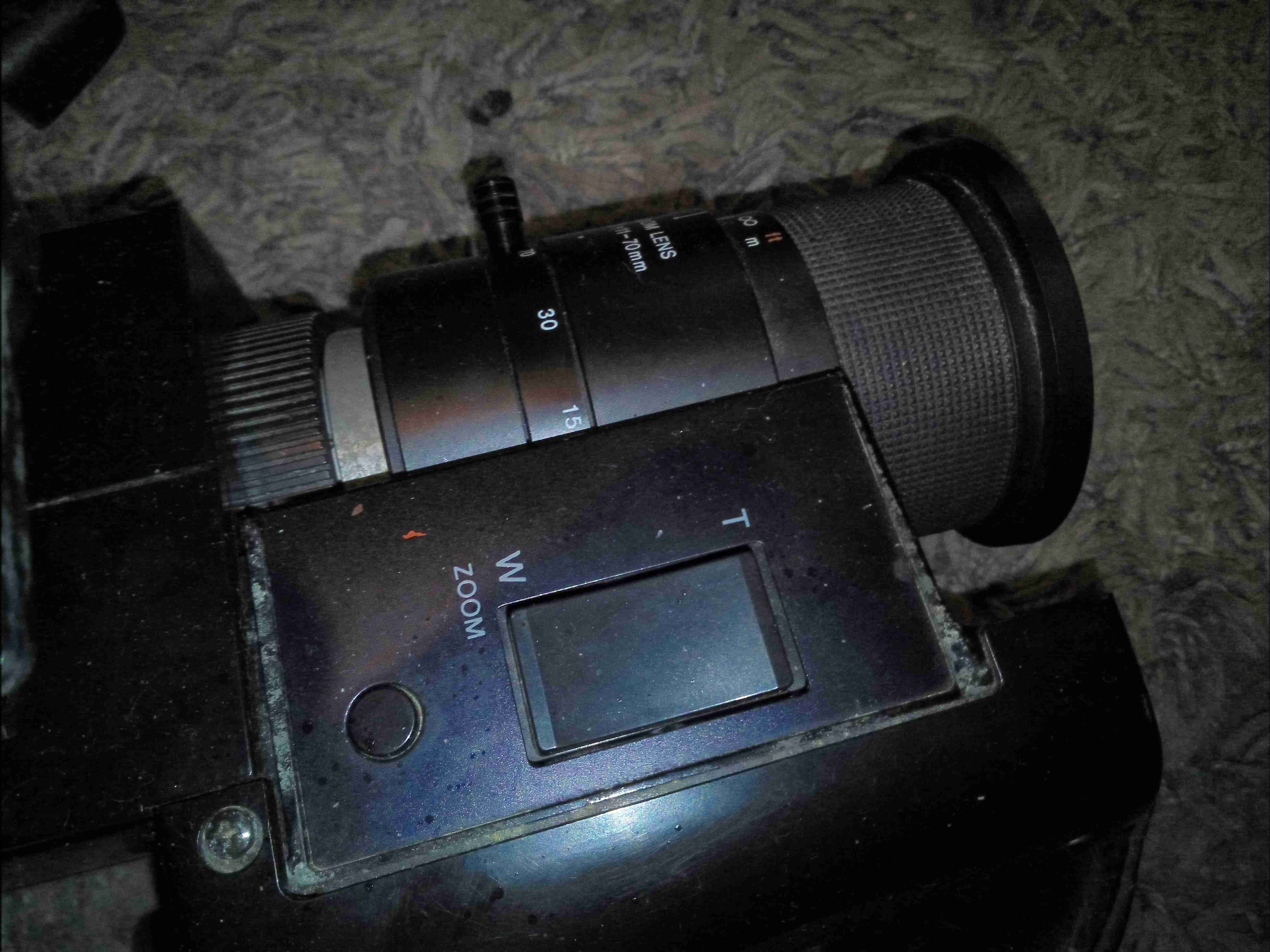
The Zoom controls are on top of the grip, with a button to the rear of the control which I have no idea about. The internal belts are a bit rotted with age so the zoom function doesn’t work great.
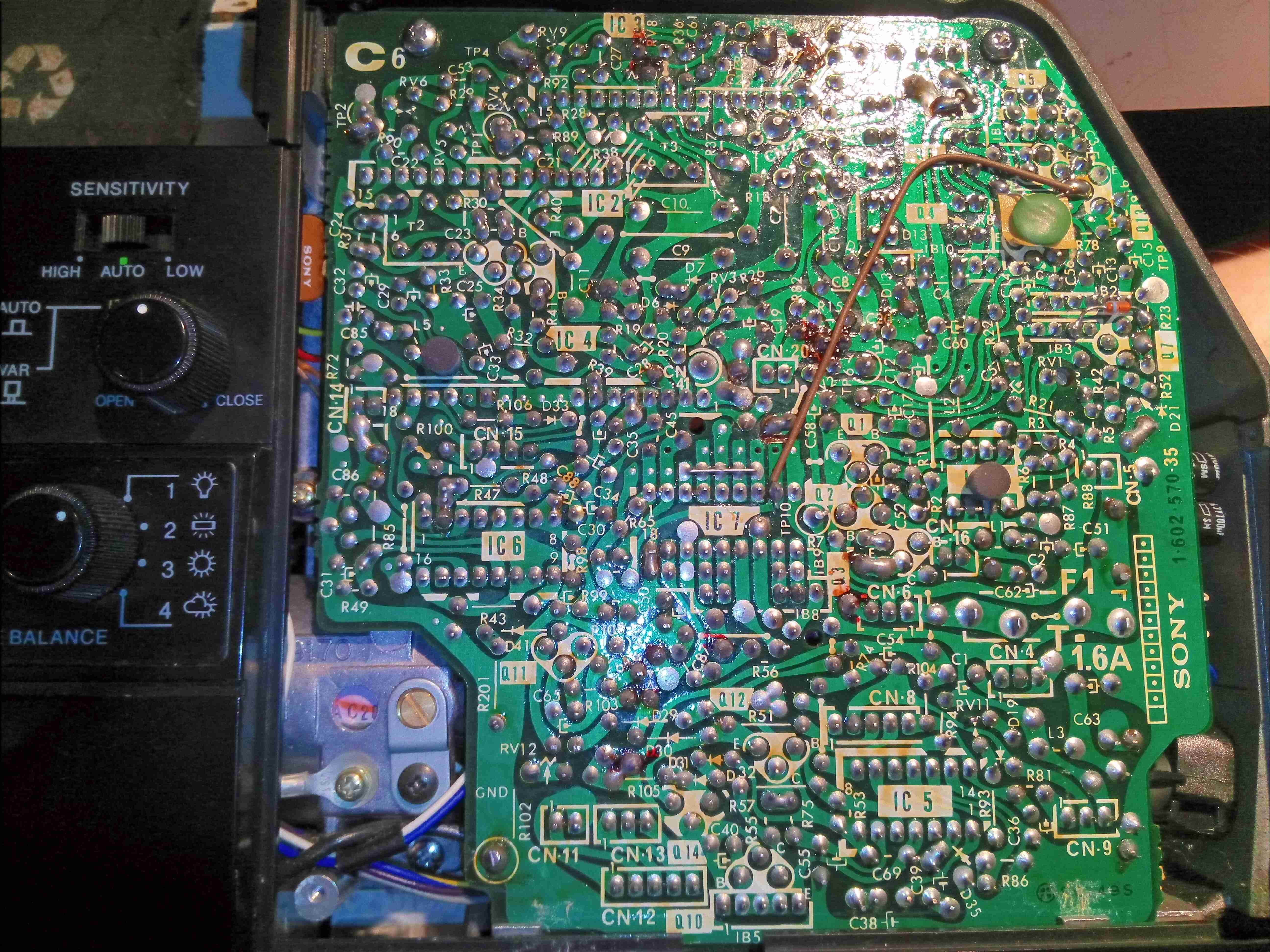
After removing the side covers, the two large PCBs become visible. These units are absolutely packed with electronics. On this side is the Trinicon tube control board, generating all the high voltages for electron beam acceleration, focus & electrostatic deflection of the beam. There’s around 500 volts knocking around on this board, with some rather specialised hybrid modules doing all the high voltage magic.
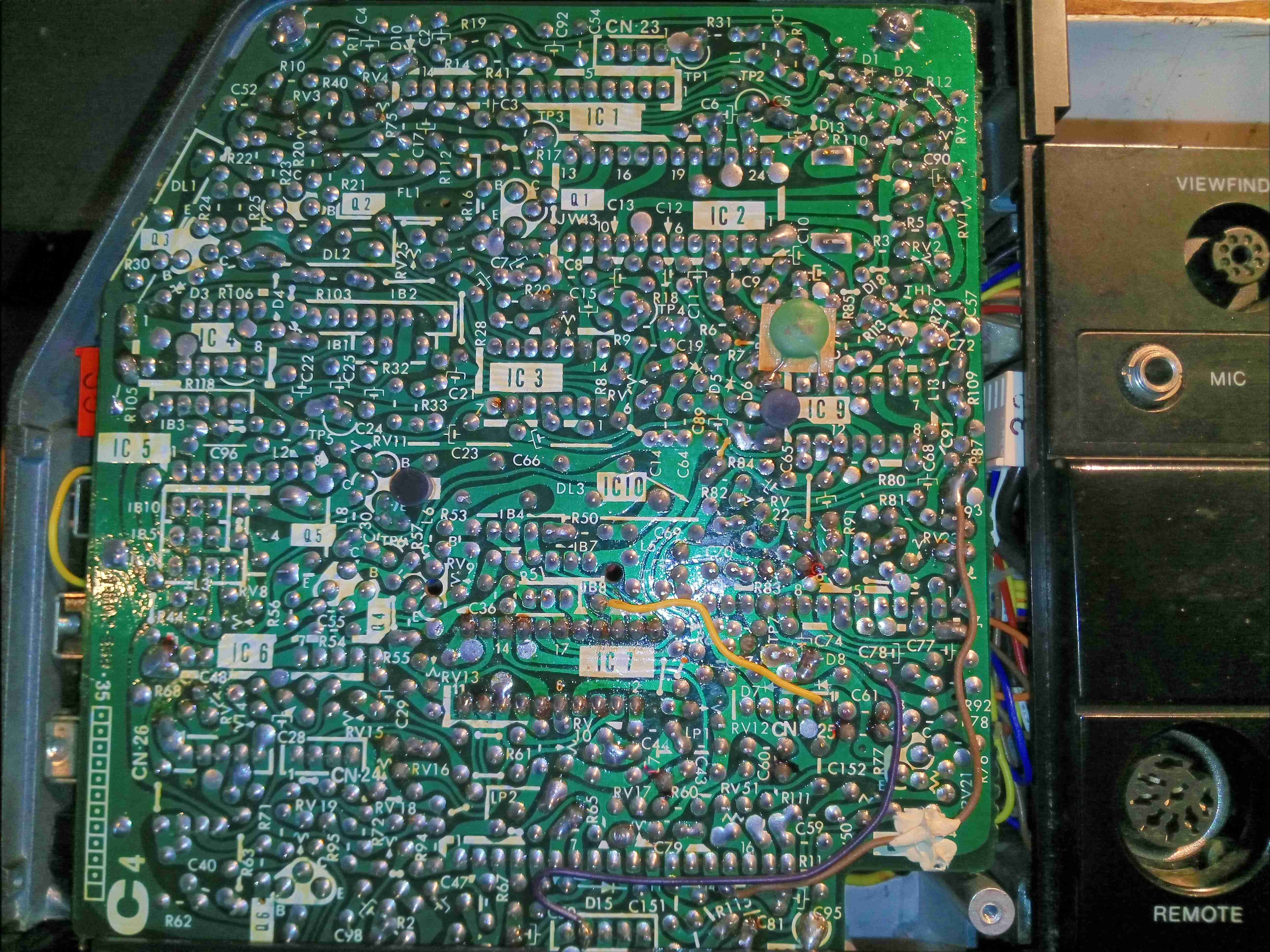
The other side of the camera has the video process board, which performs all the colour separation of the video signal from the tube, processes the resulting signals into a composite video signal, and finally sends it down the umbilical.
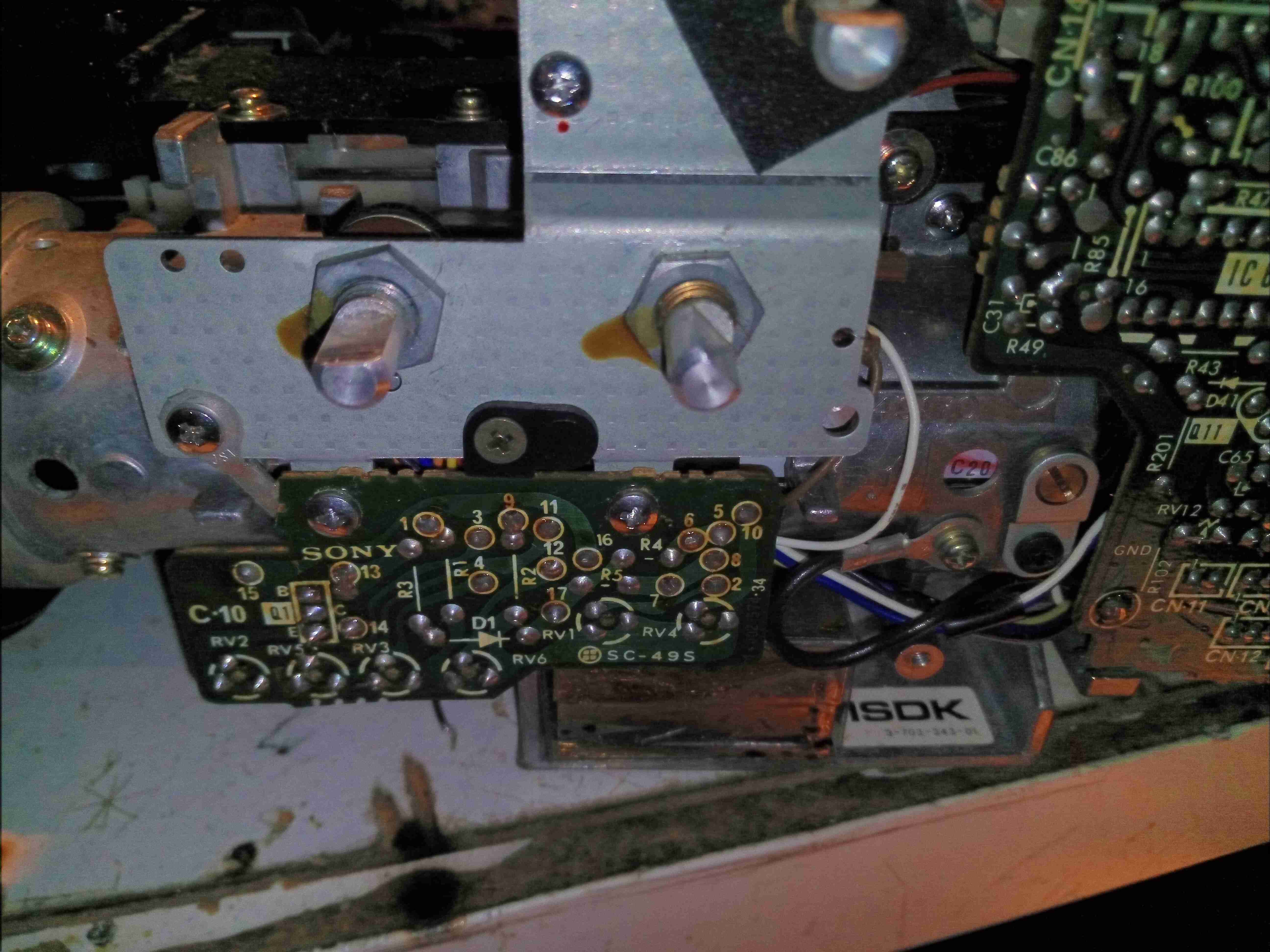
Removing some of the remaining covers exposes the bare video controls, and a small PCB just underneath covered in trimpots to set factory levels.
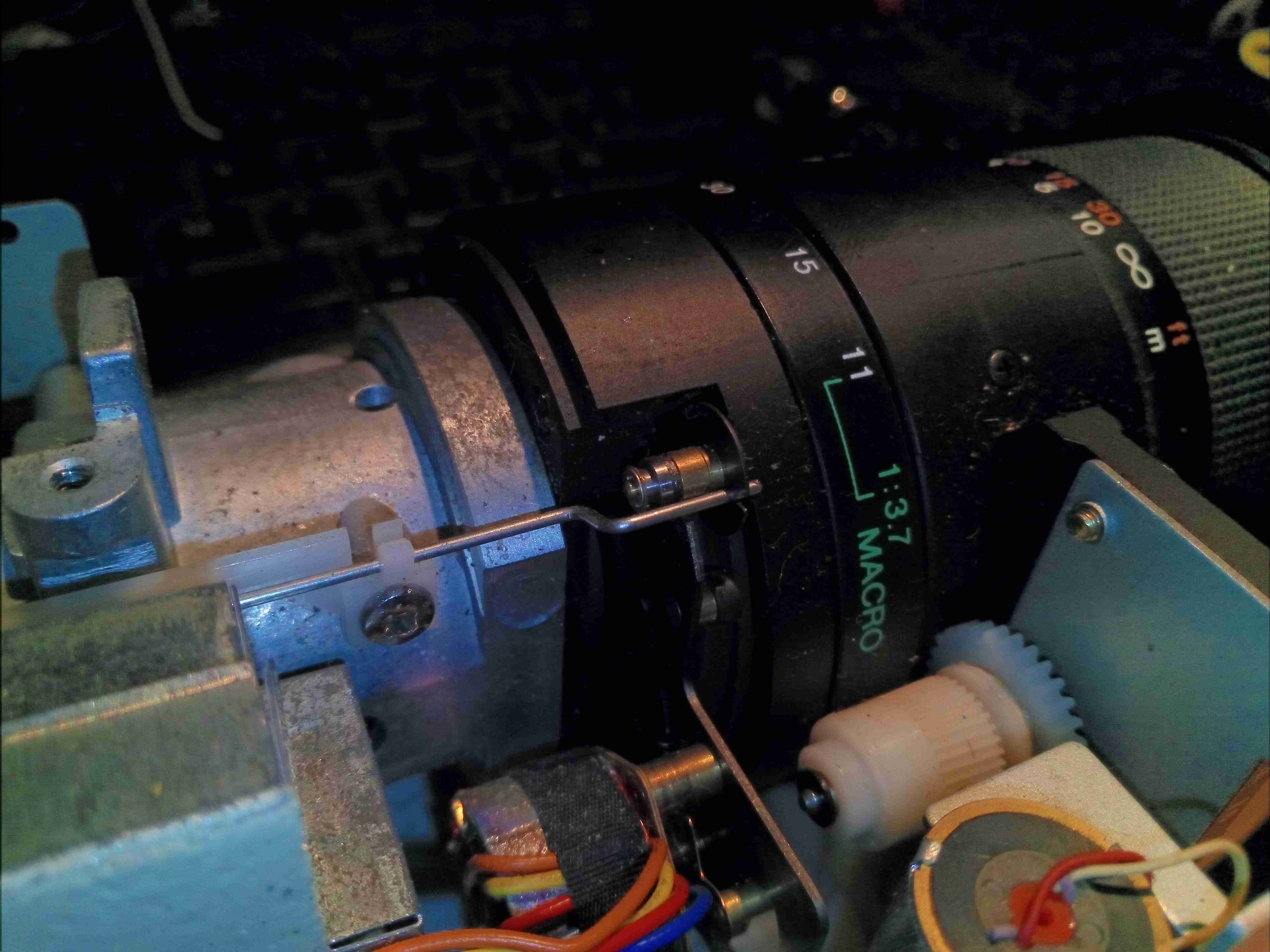
The white balance is partially electronic & partially mechanical. This lever actuates a filter inside the lens assrembly.
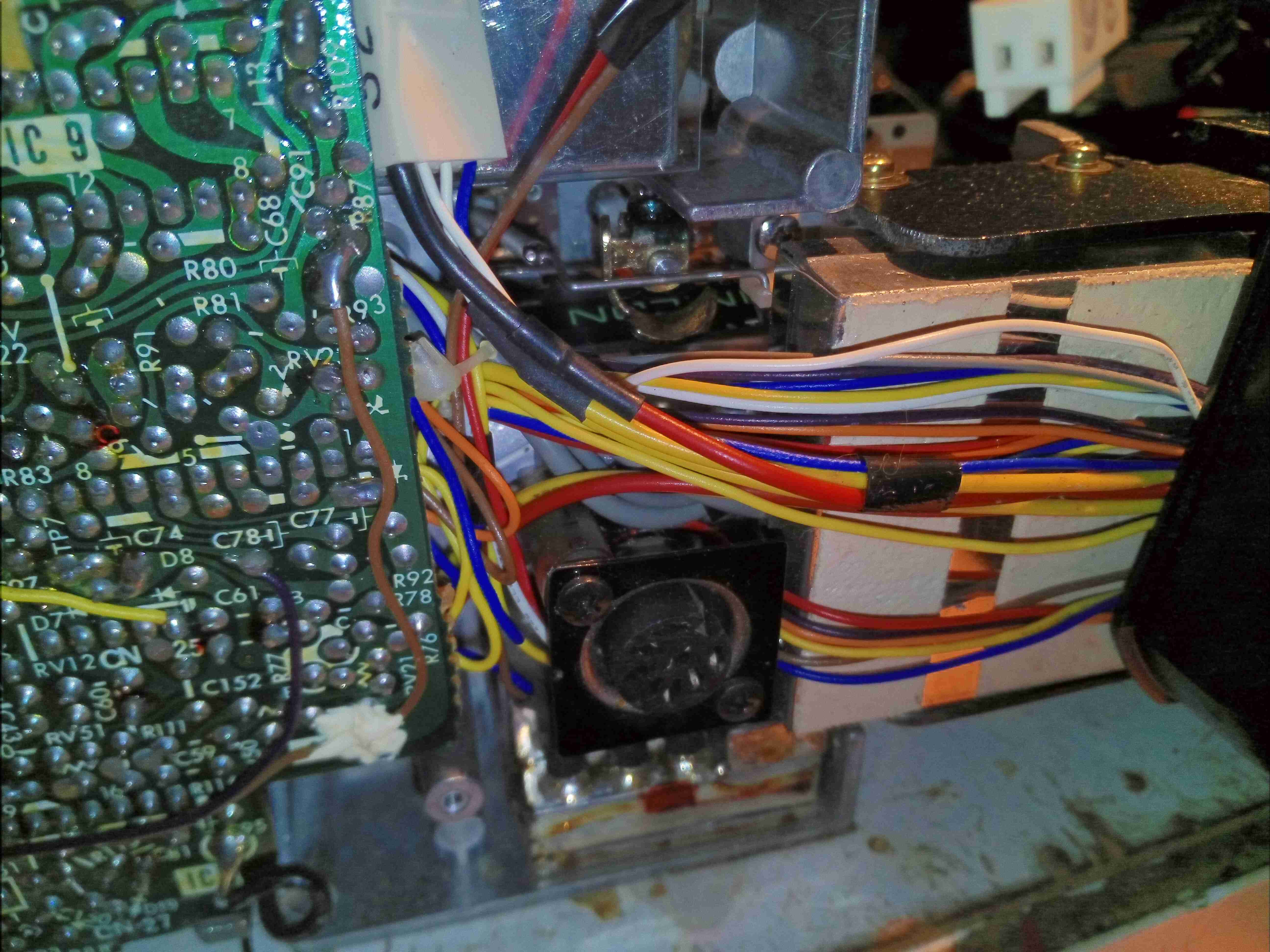
A DIN connector offers remote control ability. The large loom of wires disappearing off to the right is dealing with the zoom mechanism & the onboard microphone amplifier. Just under the DIN connector hides the system power supply, inside a soldered can. The can under the white tape is the head end amplifier for the Trinicon video tube.
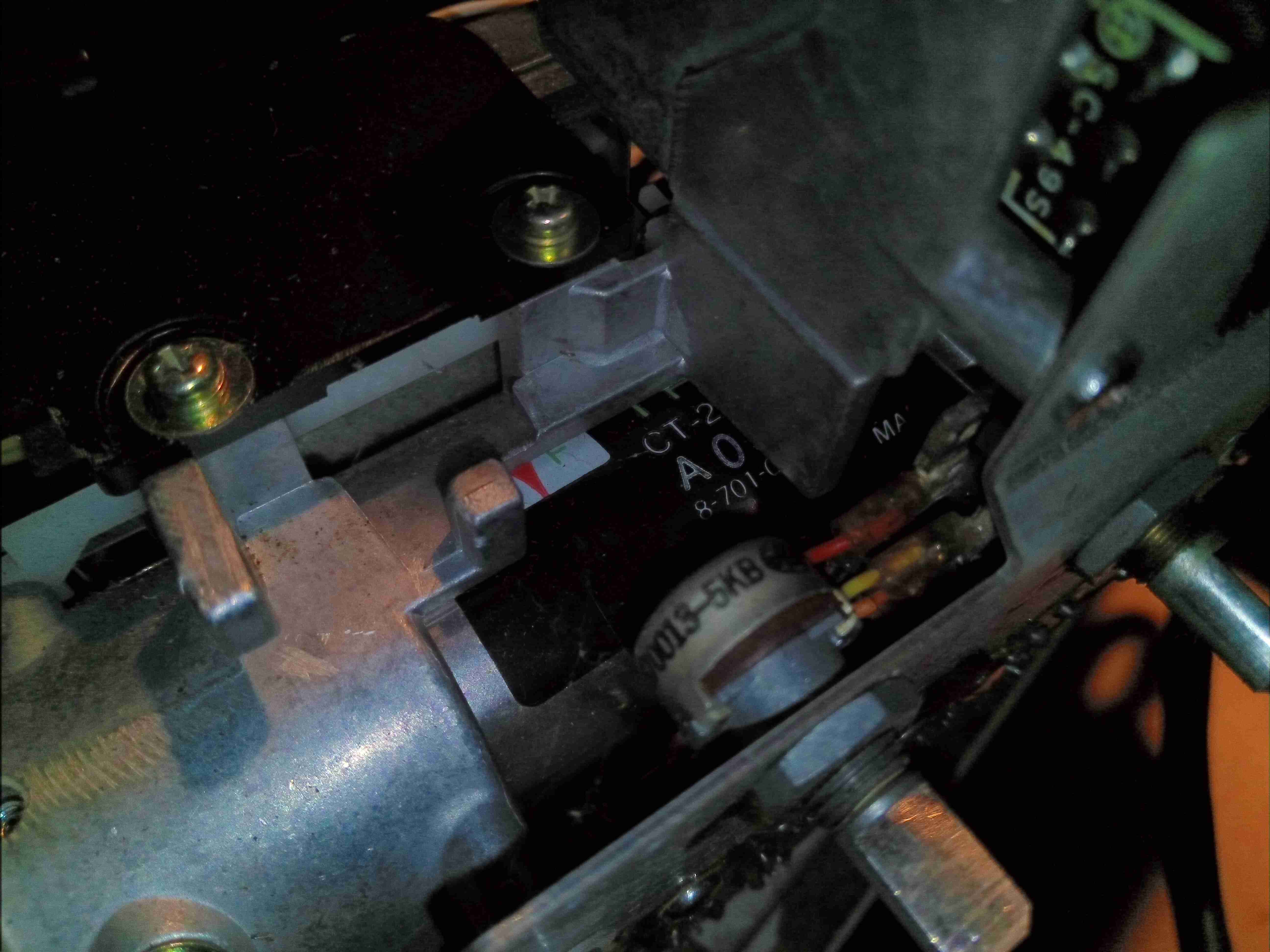
Hiding in the centre of the camera inside the casting is the Trinicon tube assembly itself. The label can just be seen here.
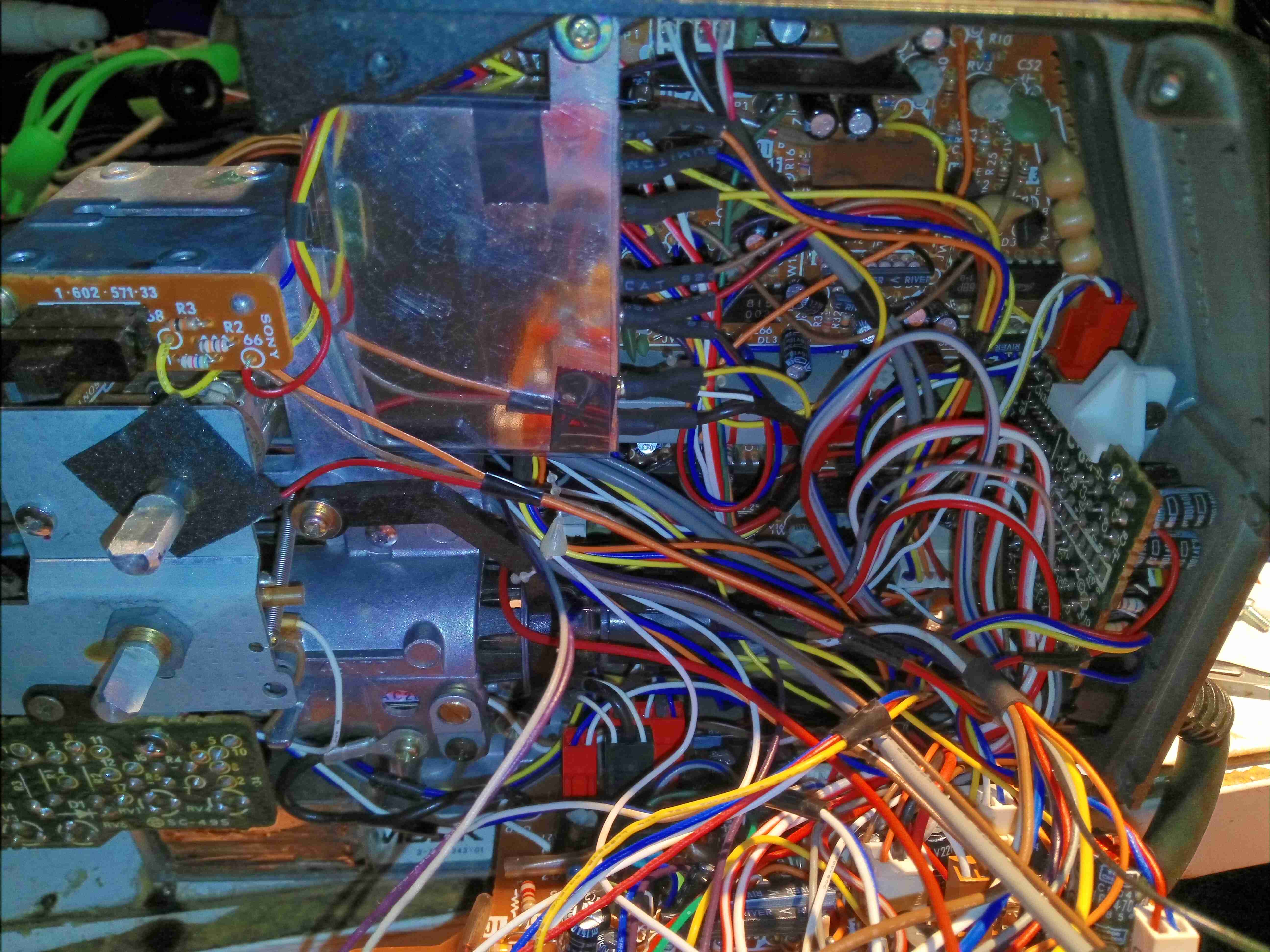
As is typical of 1980’s electronic design, the main boards swing down & are designed to slot into the base casting folded out for repairs. Internally the unit is a rat’s nest of wiring loom. There’s also another shielding can in here nestled between the boards – this is the video sync generator circuit.
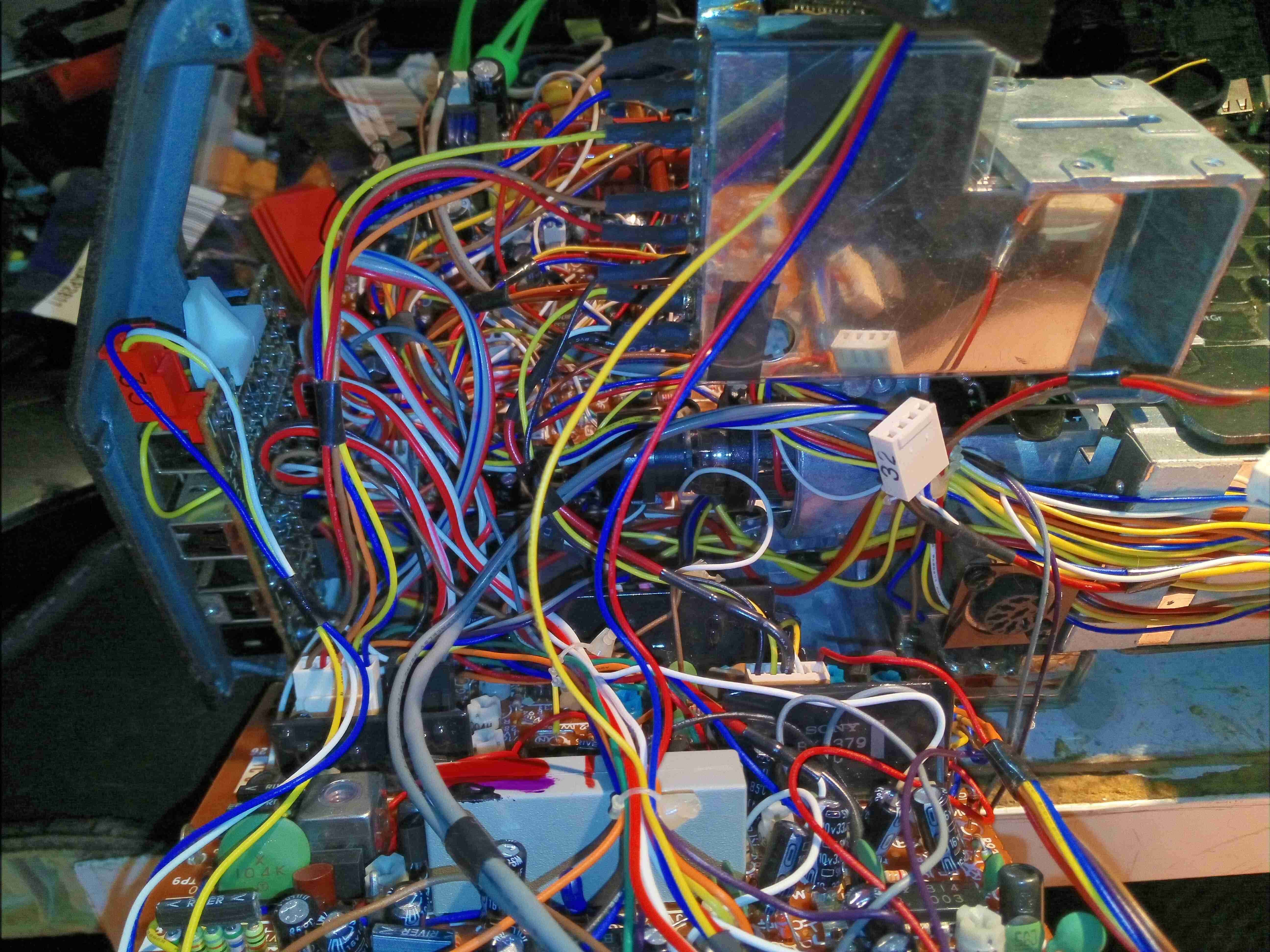
The other side gives a better view of the video sync generator can. I’ll dive into the individual modules later on.
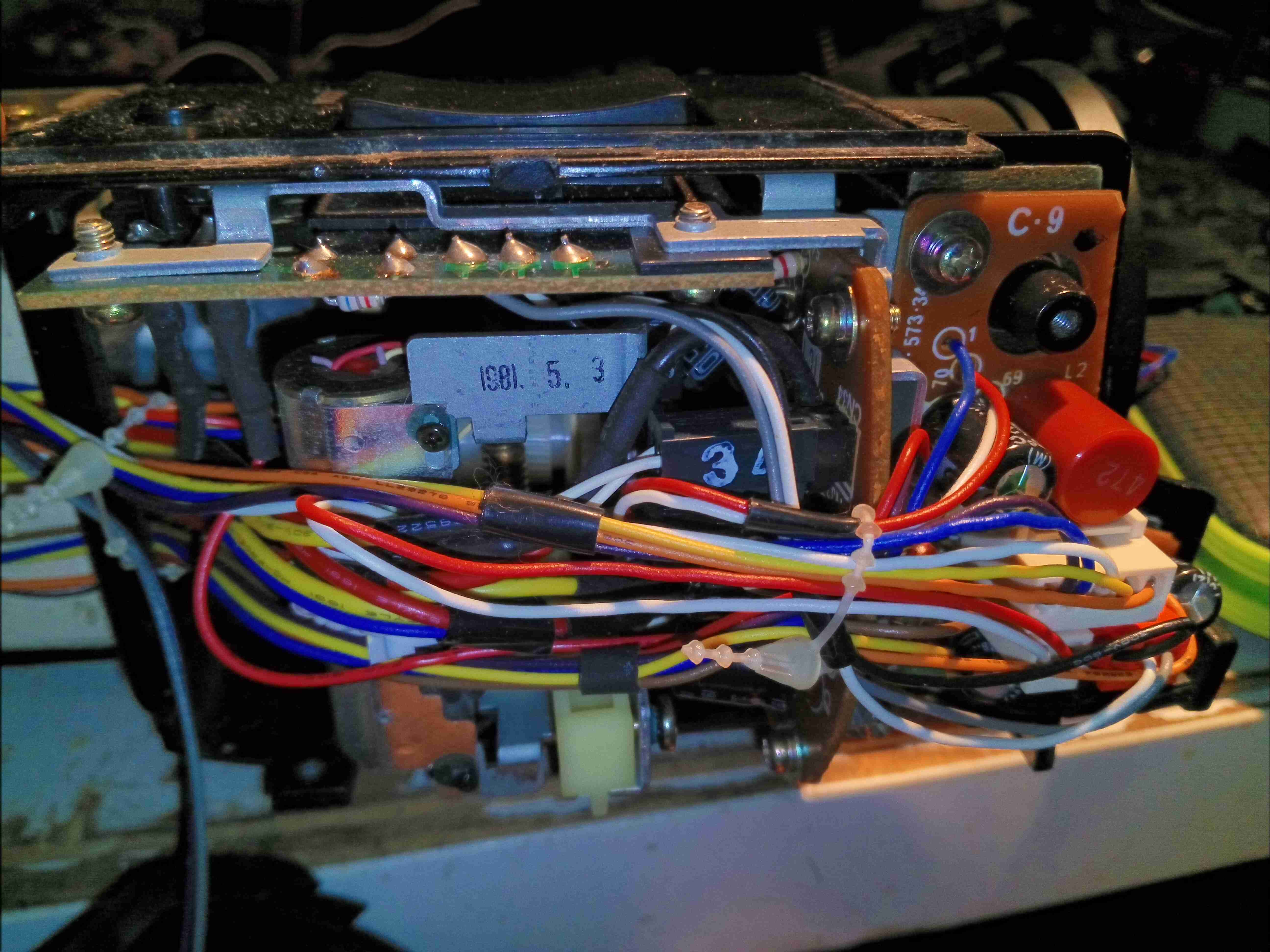
Under the remaining side cover is the zoom assembly & microphone amplifier board. More massive wiring loom hides within.
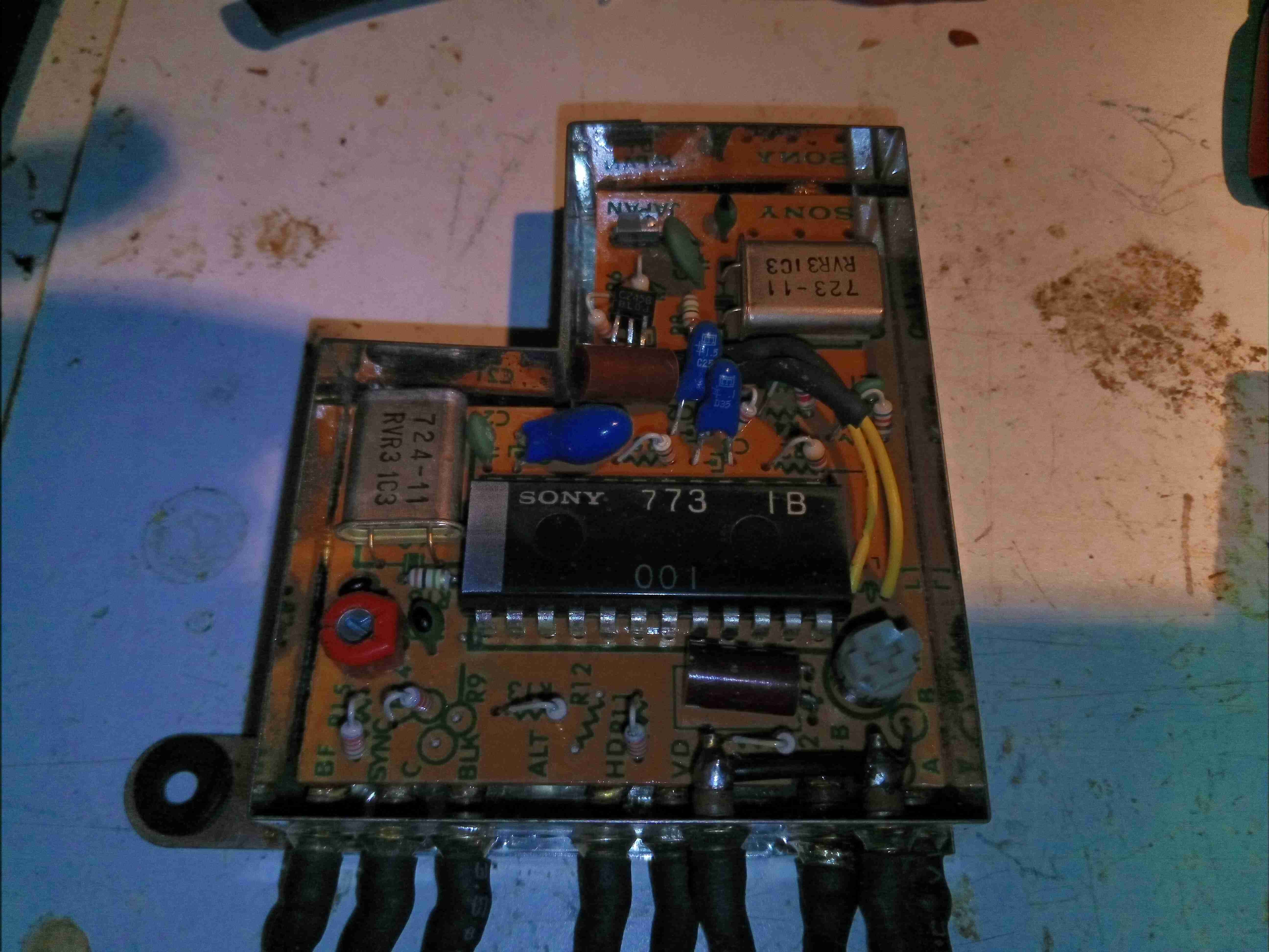
The video sync generator is pretty sparse inside, just a large Sony CX773 Sync Generator IC, with a pair of crystals. There are a couple of adjustments in here for video sync frequencies.
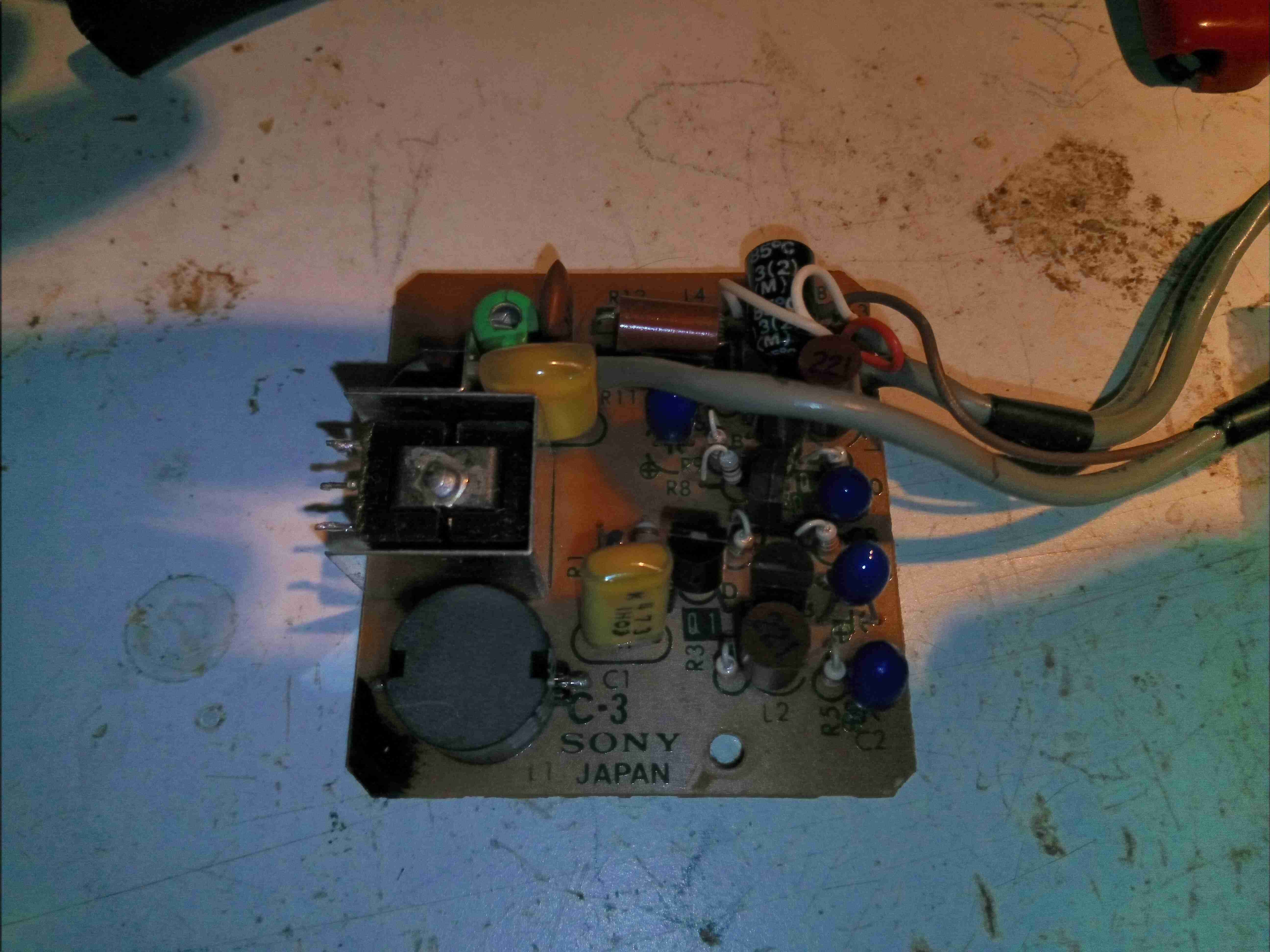
Removed from it’s shielding can, here is the head end amplifier for the Trinicon tube. This very sensitive JFET input amplifier feeds into the main video process board.
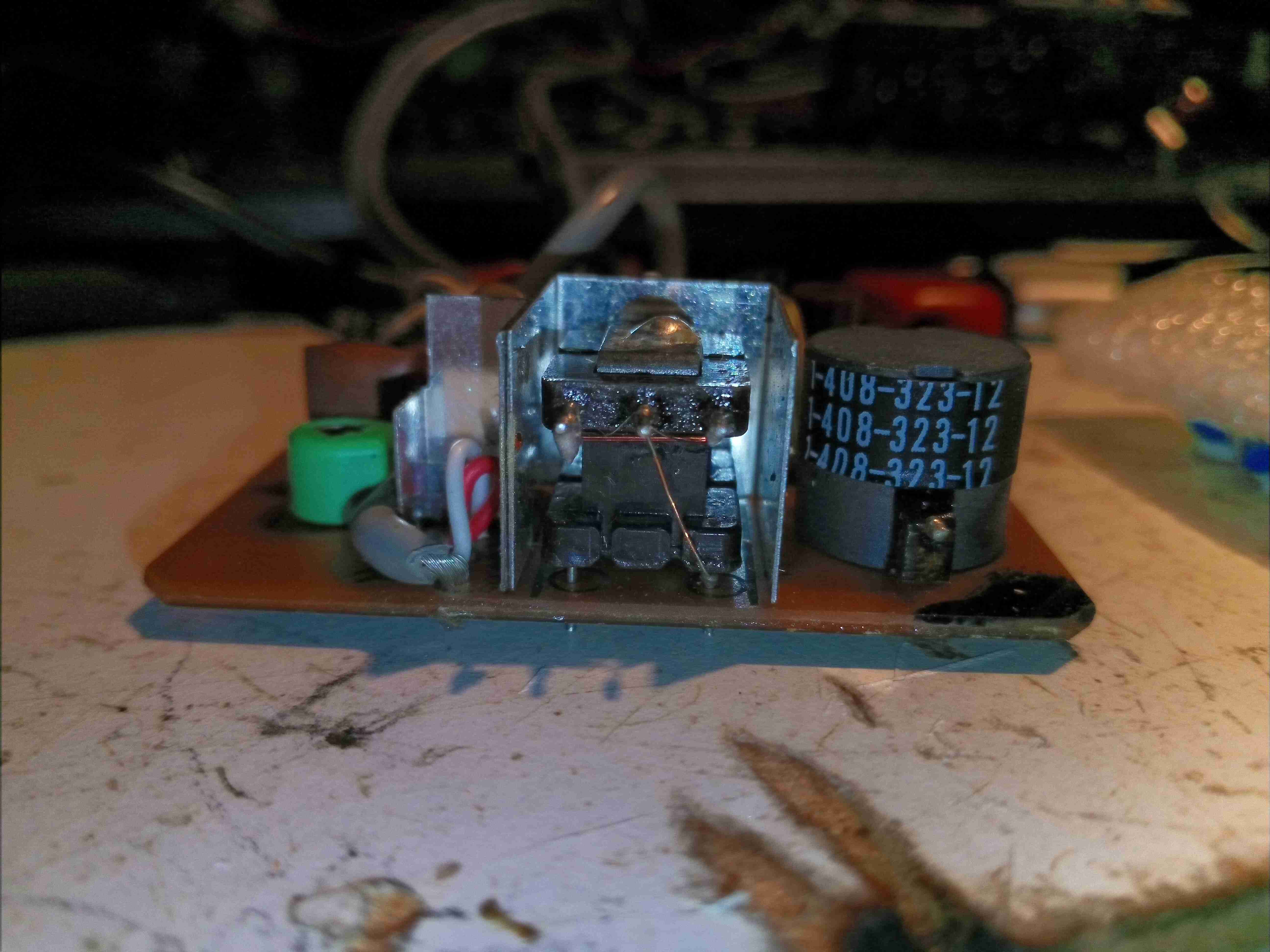
The Trinicon tube target connects to this input transformer on the front of the amplifier board.
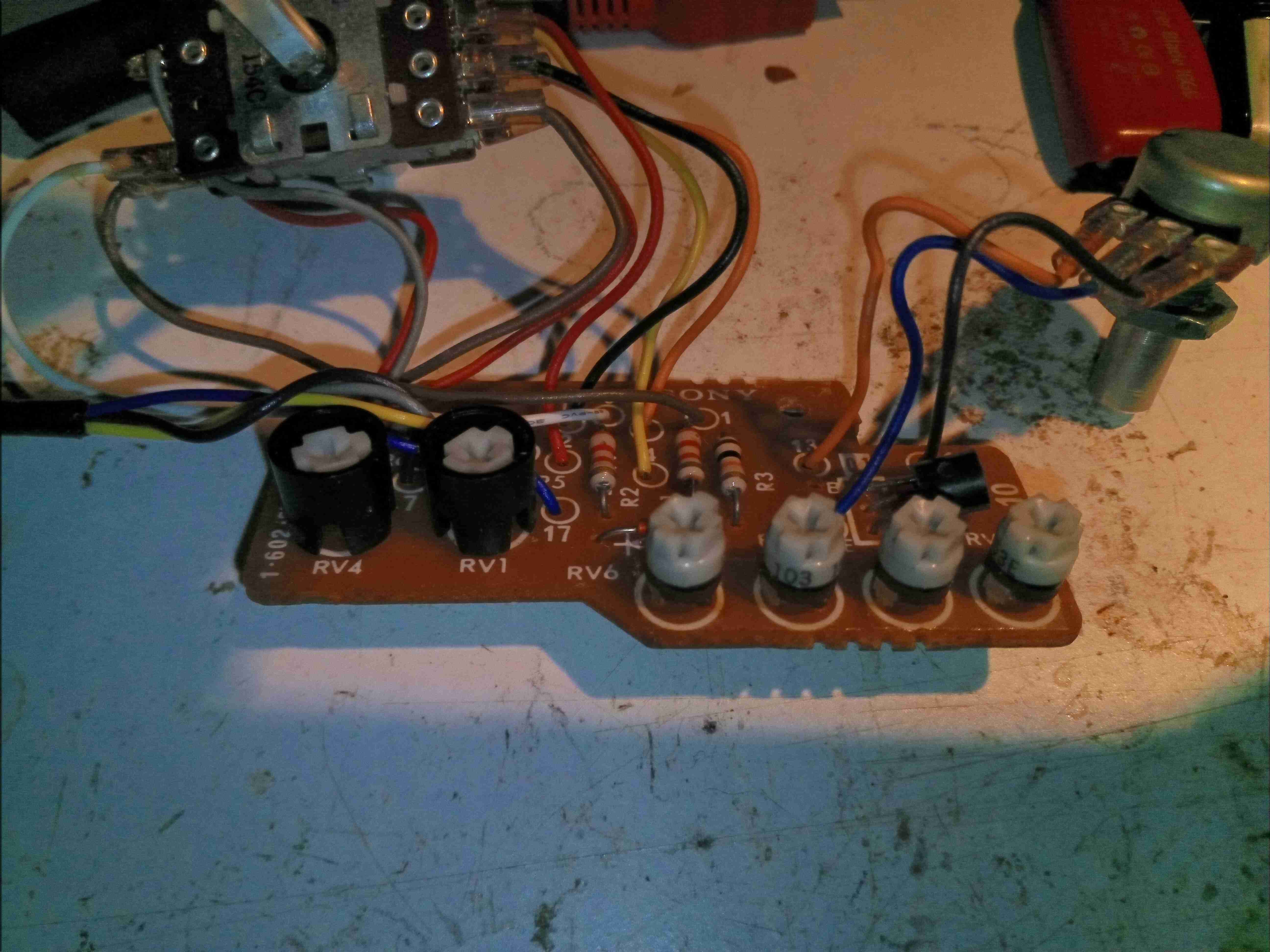
The internal white balance controls are on this small PCB, mounted under the user-accessible controls.
Here’s the main control board responsible for the Trinicon tube & exposure control. Down near the front is the auto-iris circuit, nearer the centre is timing control & at the top is the high voltage power supply & deflection generator ICs.
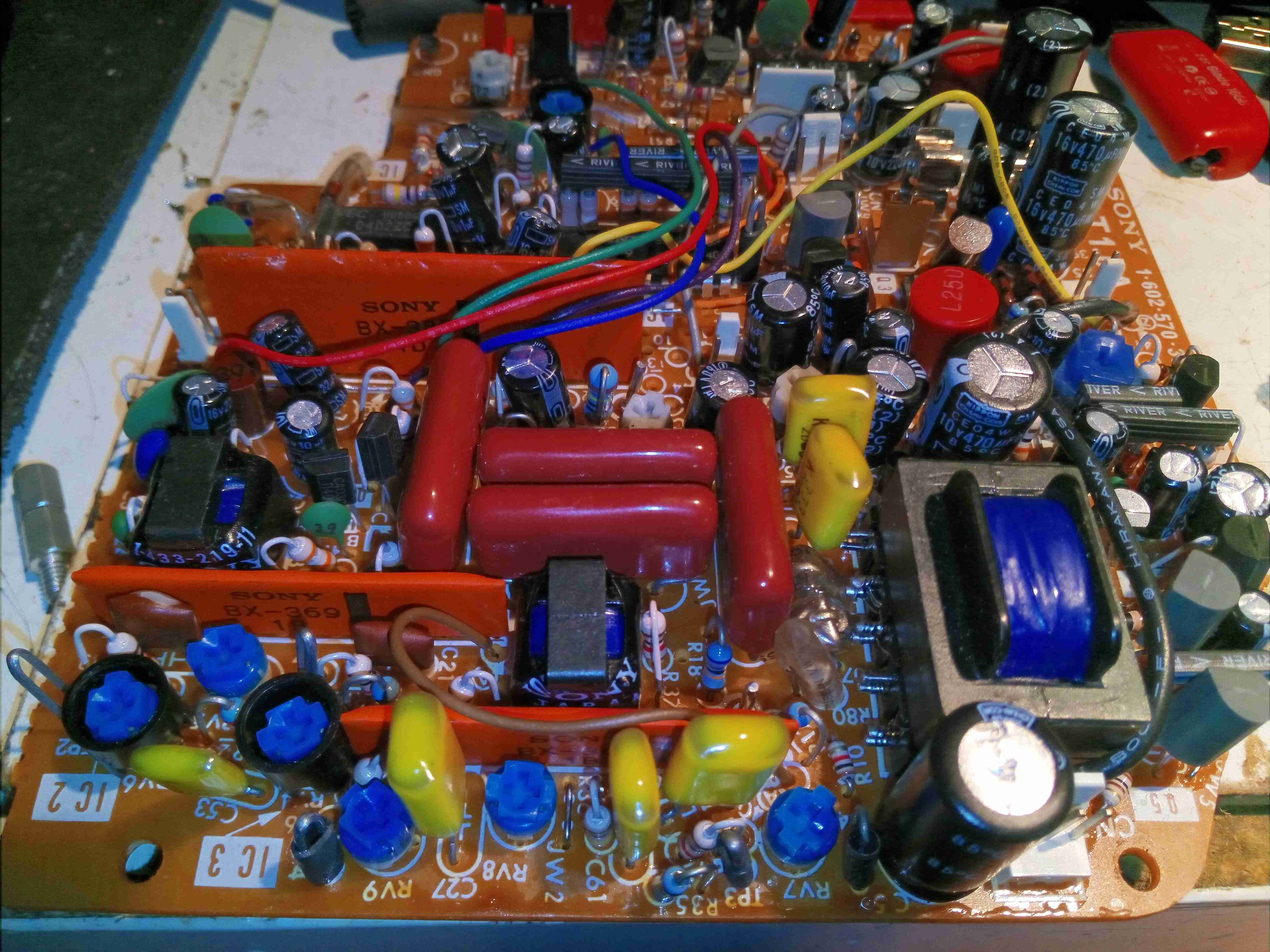
Here’s the high voltage section, the main transformer at right generating the voltages required to drive the video tube. The large orange hybrids here are a pair of BX369 high-voltage sawtooth generators that create the deflection waveforms for the tube. The other large hybrid is a BX382 Fader Control.
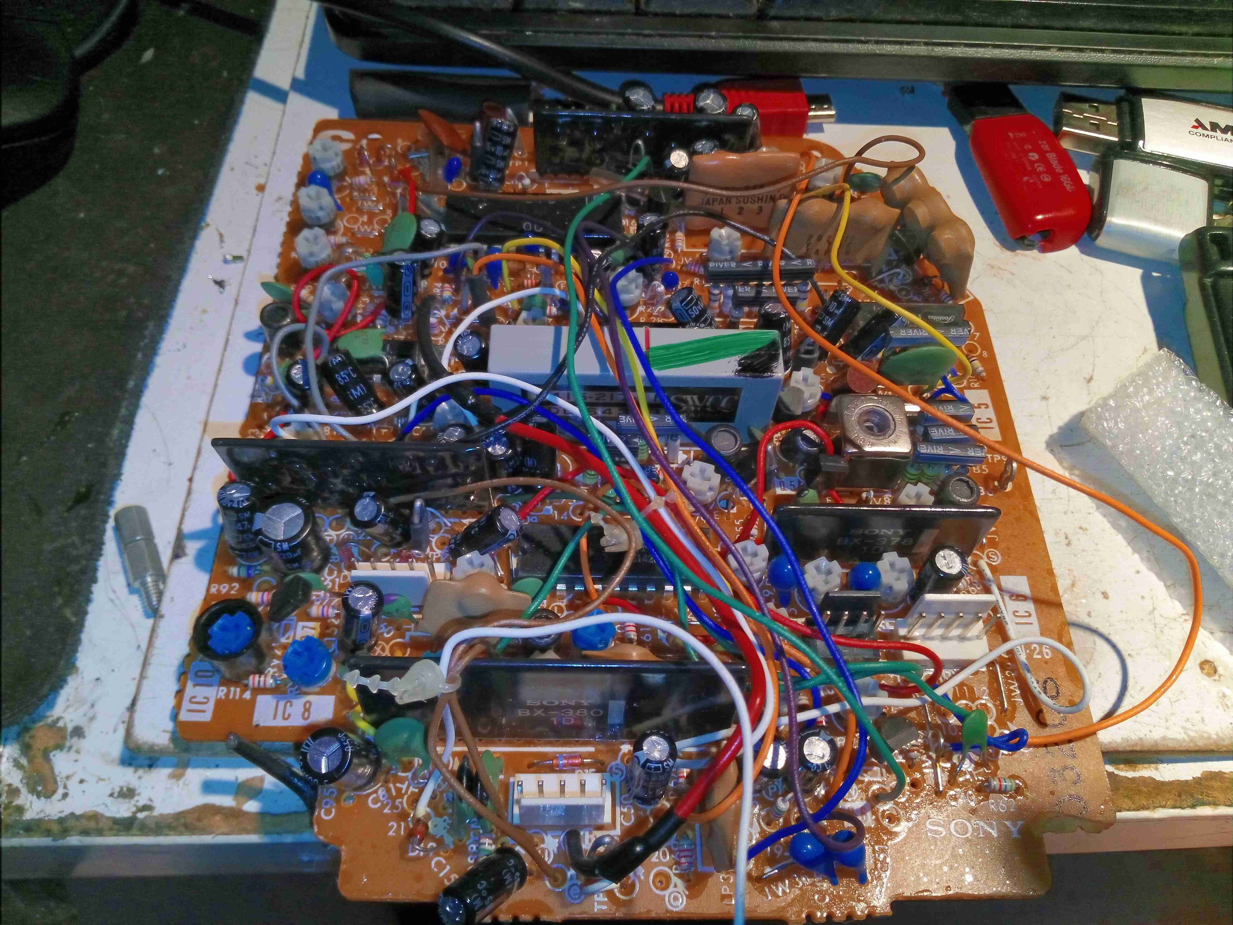
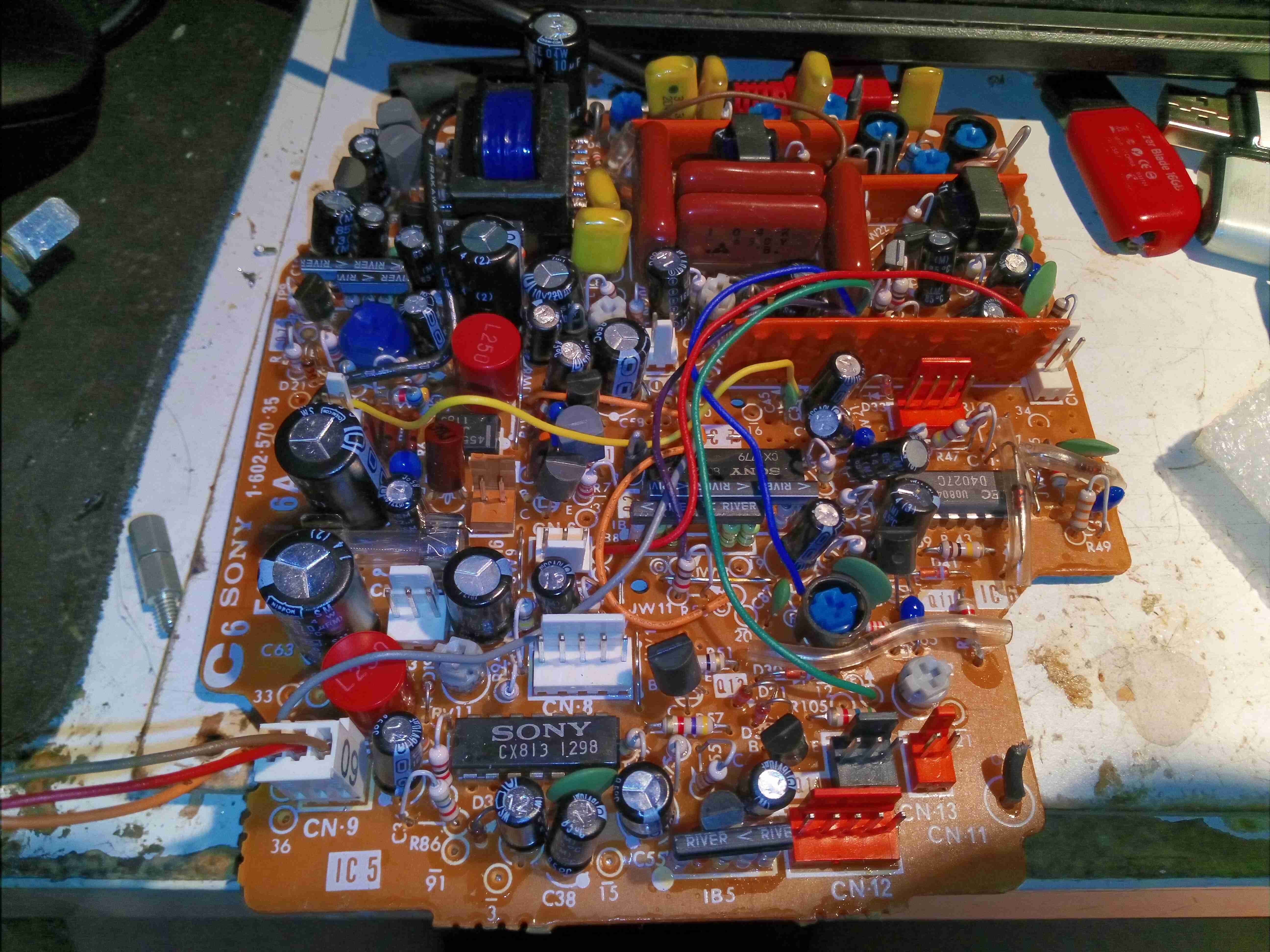
The other large board contains all the video process circuitry, all analogue of course. There are a lot of manual adjustment pots on this board.
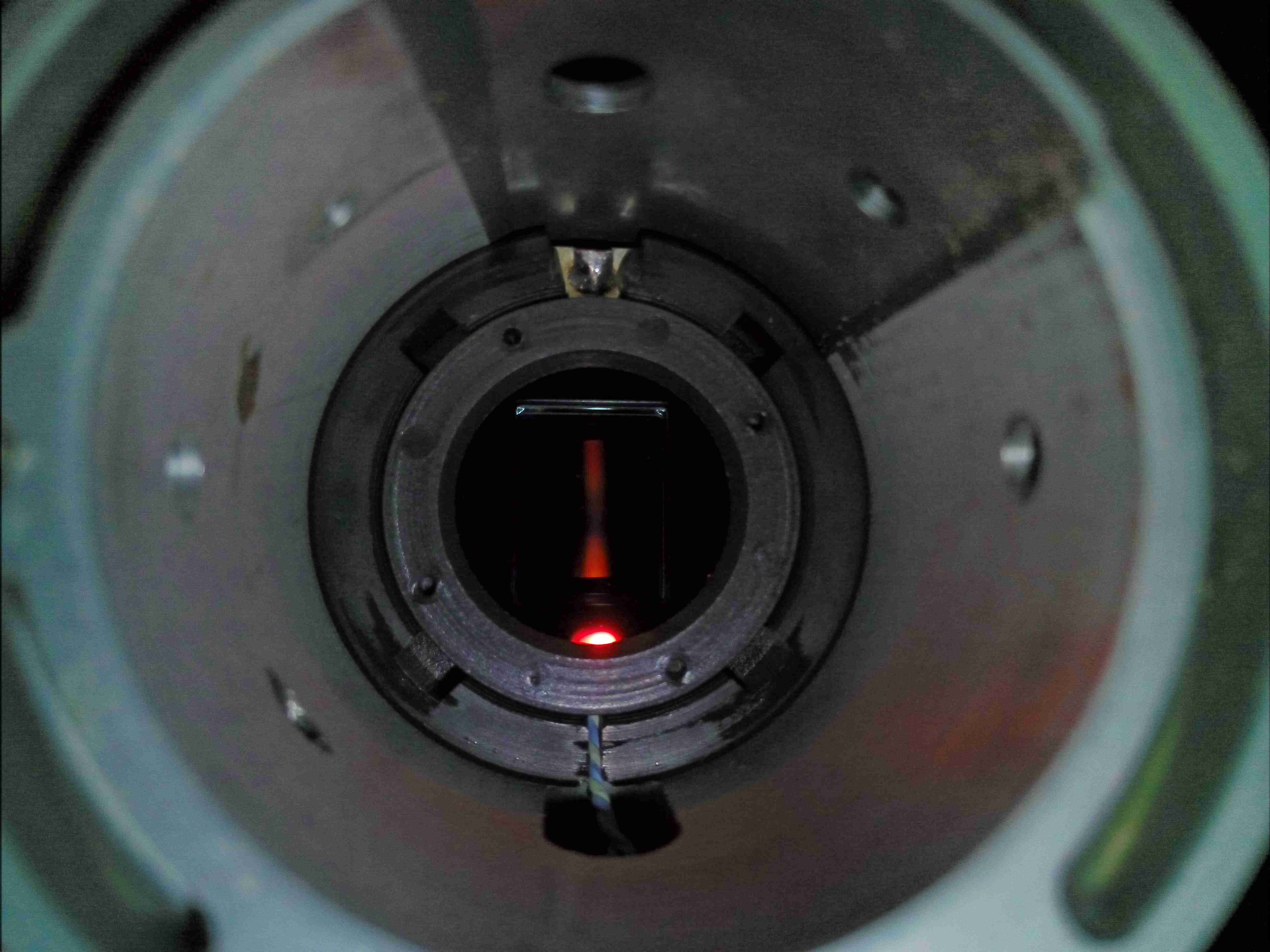
After removing the lens assembly, the tube assembly is visible inside the barrel casting. Not much to see yet, just the IR filter assembly.
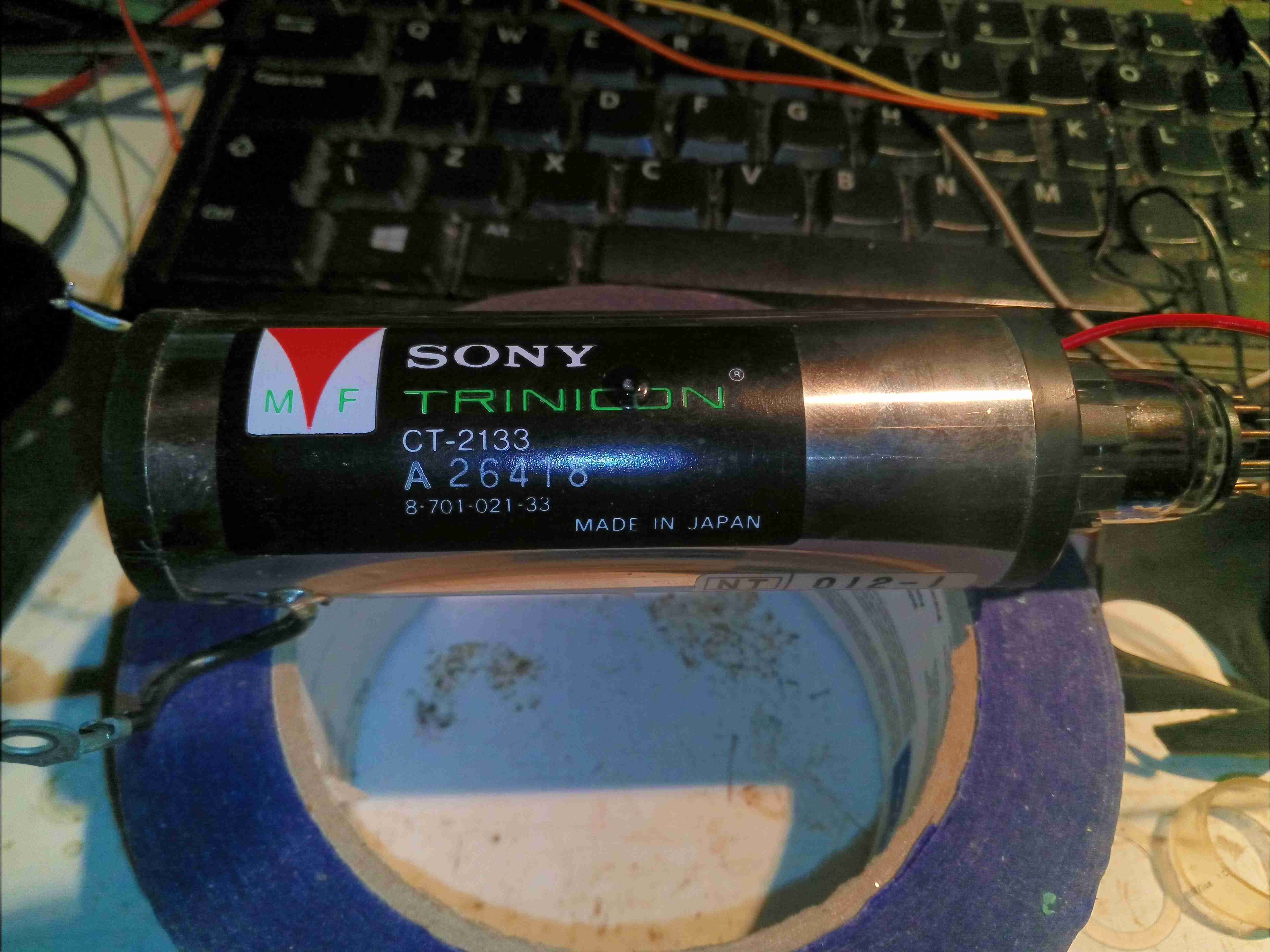
Here’s the unit removed from the camera. Unfortunately this tube is dead – it shows a lot of target burn on the resulting image, and very bad ghosting on what poor image there is. The Trinicon tube itself is encased in the focus coil assembly, the windings of which are hidden under the shielding.
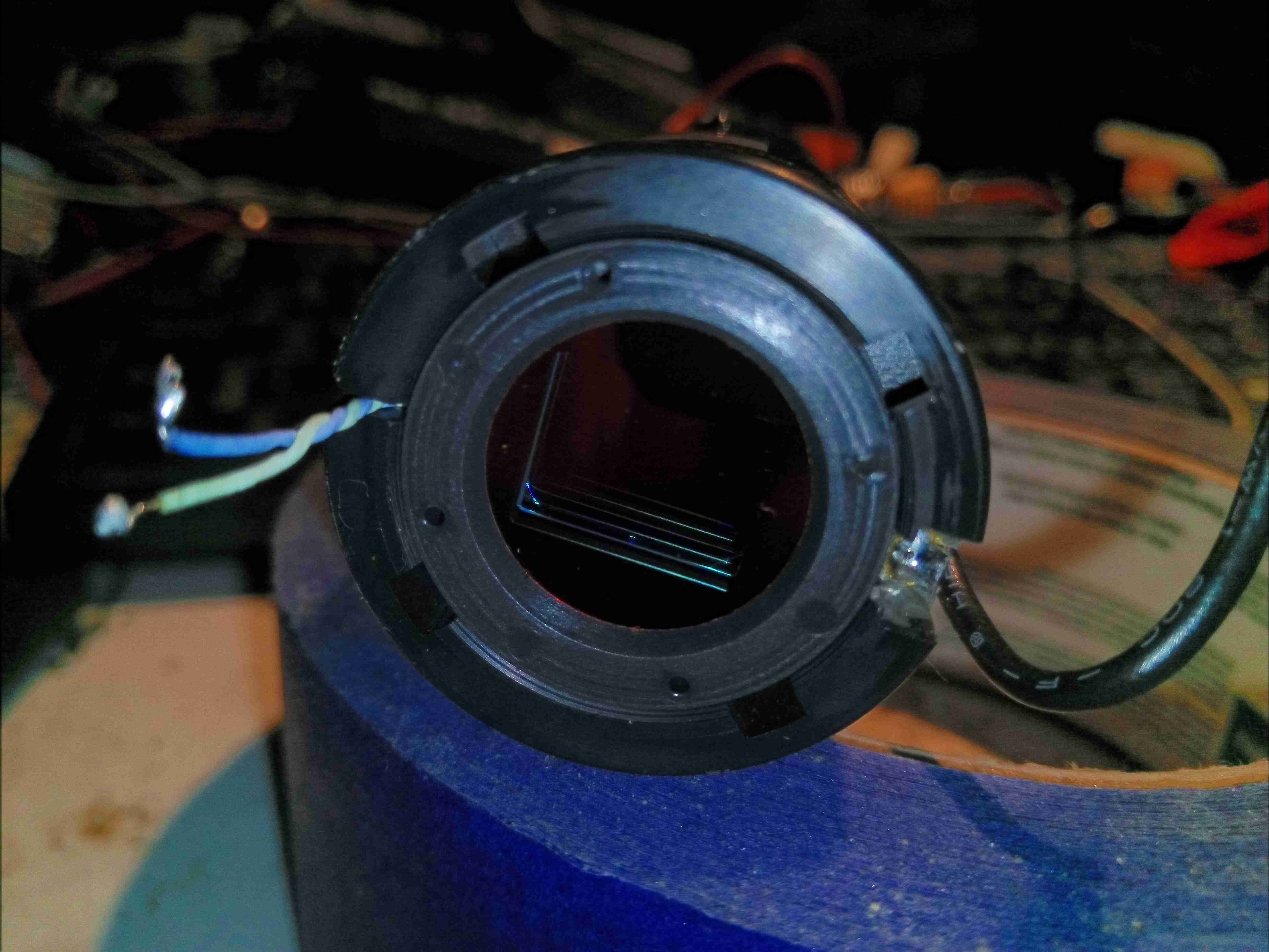
The IR filter is locked into the front of the tube, on a bayonet fitting. The twin target wires are running off to the left, where they would connect to the head end amplifier.
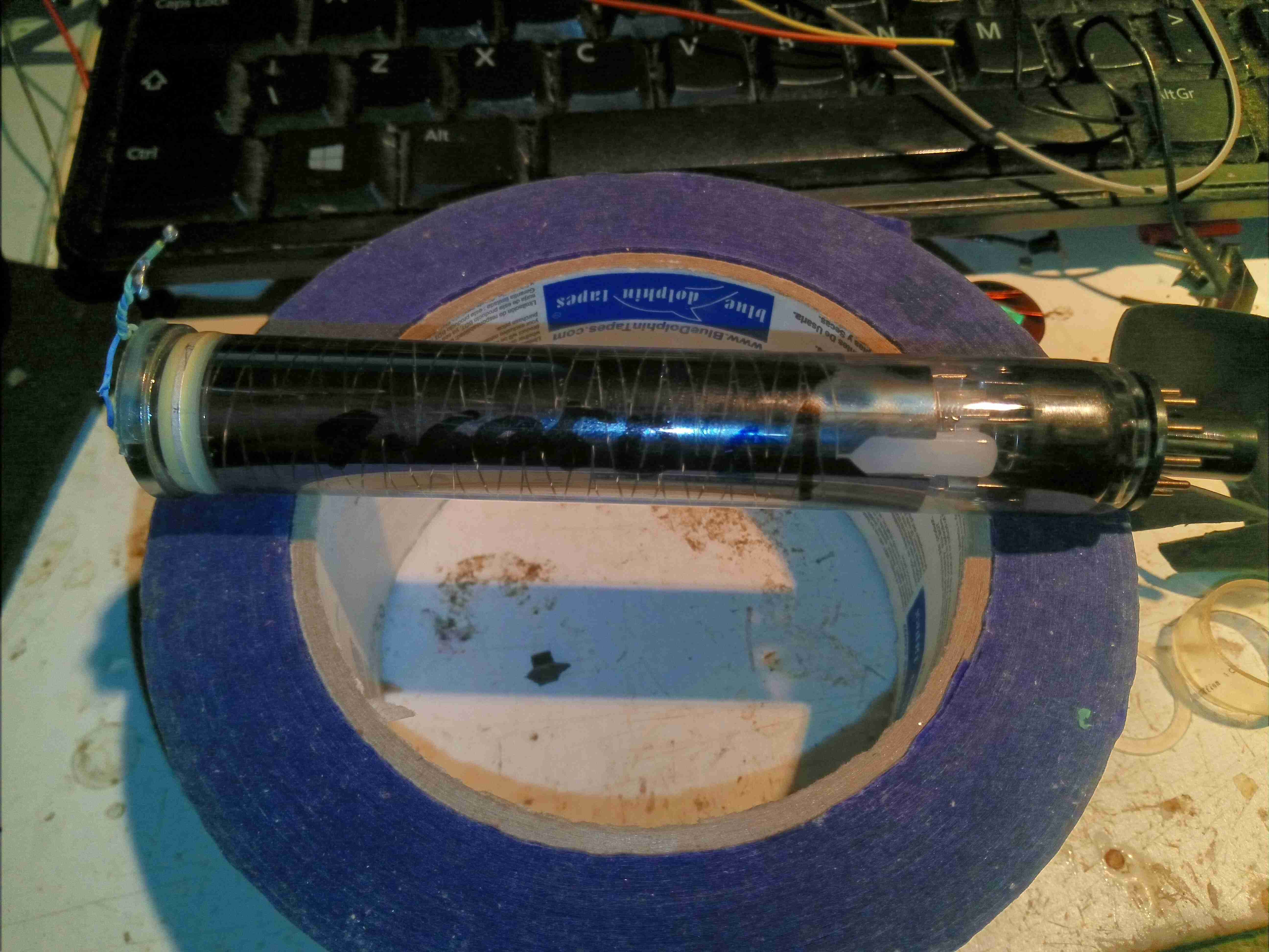
After removing the IR filter glass, the Trinicon tube itself is removed from the focus coil assembly. There’s an electron gun at the rear of the tube, like all CRTs, although this one works in reverse – sensing an image projected on the front instead of generating one.
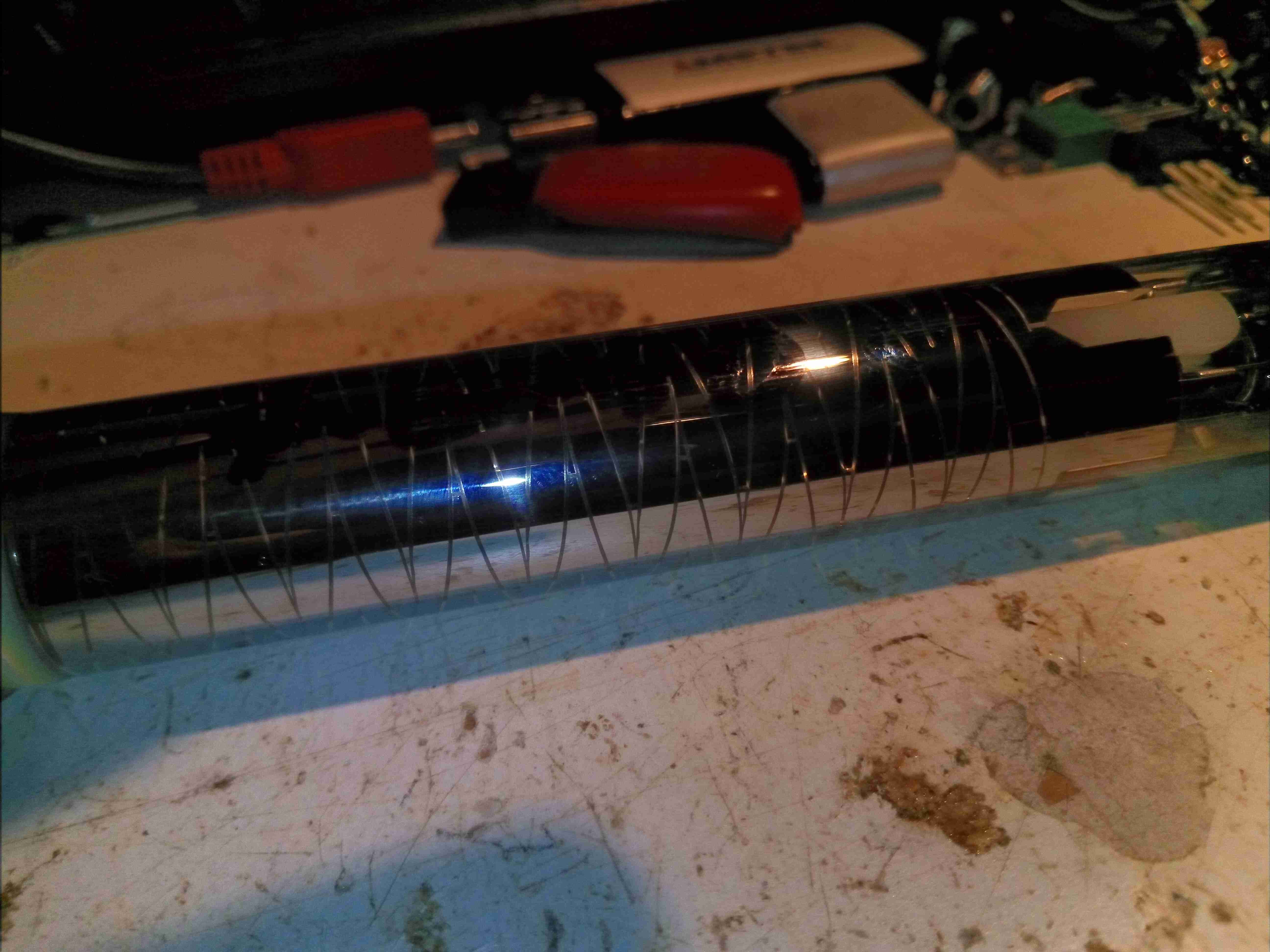
It’s a little difficult to see, but the electrostatic deflection electrodes in this tube are created from the aluminium flashing on the inside of the glass, in a zig-zag pattern. The interleaving electrodes are connected to base pins by spring contacts at the electron gun end of the tube.
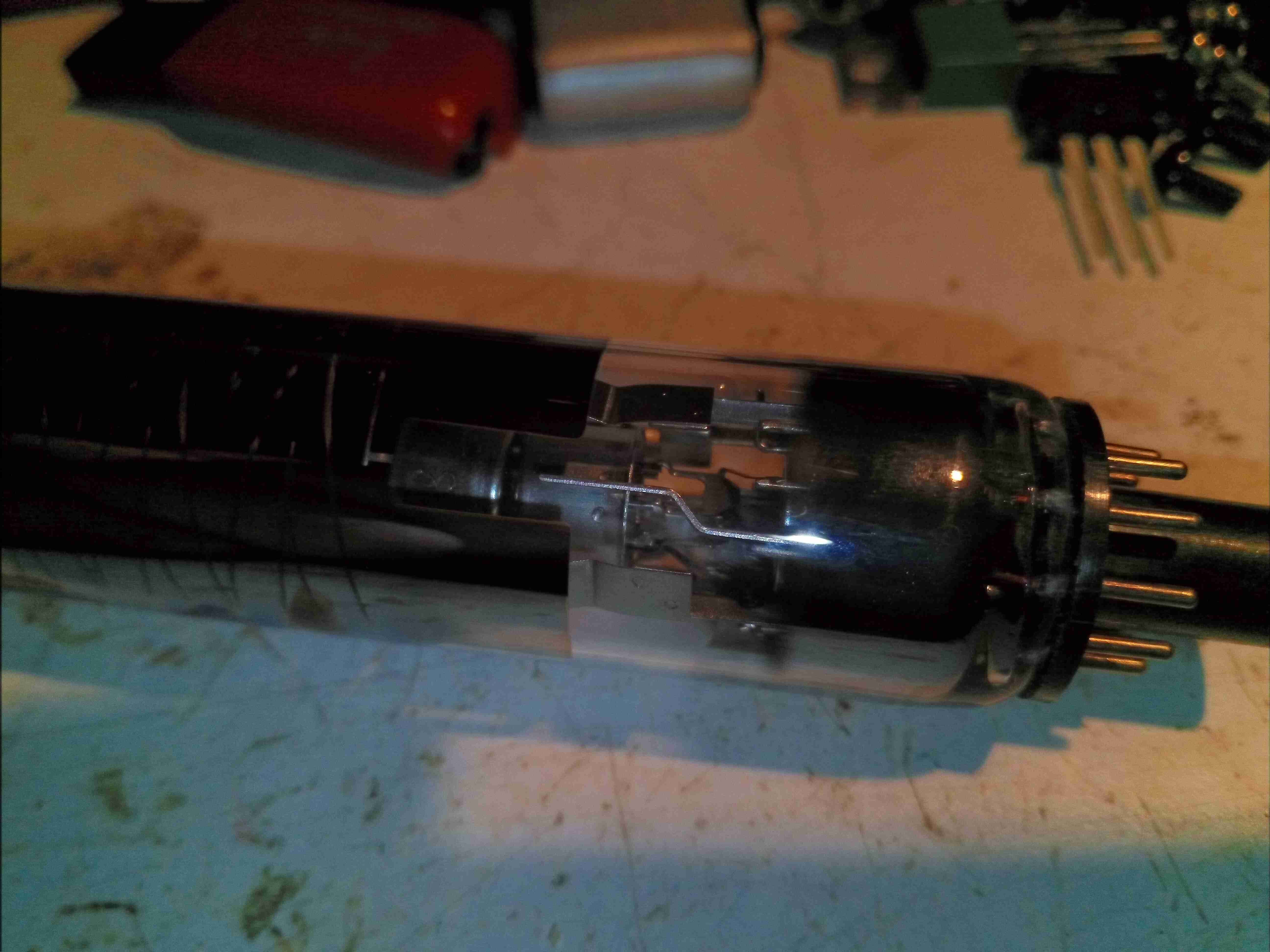
The electron gun is mostly hidden by the getter flash & the deflection electrodes, but the cathode can is visible through the glass, along with the spring contacts that make a connection to the deflection electrodes. This is also a very short gun – it doesn’t extend more than about 5mm into the deflection zone. The rest of the tube up to the target is empty space.
Finally, here’s the target end of the tube. I’m not sure how the wires are attached to the terminals – it certainly isn’t solder, maybe conductive adhesive?
It uses a vertically striped RGB colour filter over the faceplate of an otherwise standard Vidicon imaging tube to segment the scan into corresponding red, green and blue segments. It is used mostly in low-end consumer cameras, though Sony also used it in some moderate cost professional cameras in the 1980s.
Although the idea of using colour stripe filters over the target was not new, the Trinicon was the only tube to use the primary RGB colours. This necessitated an additional electrode buried in the target to detect where the scanning electron beam was relative to the stripe filter. Previous colour stripe systems had used colours where the colour circuitry was able to separate the colours purely from the relative amplitudes of the signals. As a result, the Trinicon featured a larger dynamic range of operation.
I have the service manuals below for the HVP-2000P & the HVP-4000P, which are very similar cameras, so these may be useful to anyone who has one of these!

Great article and teardown,
I just got a similar model, a 4000P and it worked for about 15 minutes beautifully, and then all of the sudden all went black. Still has power and one can see some noise in the blacks moving in what seems to be a signal coming through, but mo image and the iris control doesn’t change anything nor does the WB filter switch. The postivie negative still works, but no image either. Any thoughts about what this might be, amd if there is any idea about a fix? The camera looks virtually unused, but probably hasn’t been used in 35 years…so maybe something just gave in? Would appreciate any response at austin@austinsettle.net
Thank you!
Austin
Io nella mia 4000p per farla funzionare correttamente ho dovuto sostituire tutti i condensatori e letteolitici…adesso funziona benissimo, però non capisco perché non sembra mettere bene a fuoco su focale 11… Mah… C’È qualche regolazione per la messa a fuoco? Un trimmer? Grazie
Correzione: ho dovuto sostituire tutti i condensatori elettrolitici
I’m trying to learn and build a “Digital RAW Tube Camera” open source project. The idea is to treat the analogue tube camera like an analogue CCD sensor, connect it to an ADC and store the information in a 12bit DNG or RAW format. I really like the feel of tube cameras and would like to modernize its video processing to get the best quality out of it. I have many questions in mind and cannot really find answers as the technology is post internet era. I think you can help me and I would love to skype you. With your authorisation I would like to record your voice to memorise it and eventually broadcast part of it. I need to investigate the case and understand everything I can on the topic before to build a community around this project. Your help will be very precious. Thank you so much.
Best regards.
Hi Lucky,
There’s quite a lot to driving a Vidicon tube – they literally are the opposite of a CRT. They require electron beam scanning across the photosensitive target, usually electrostatically with high voltages. Focus can be done with either electromagnetic or electrostatic lenses.
The output from the target is basically a composite video signal, but at a very high impedance & low signal level. A FET input headstage amplifier is usually used here due to the impedance requirements. There are a couple of schematics for basic Vidicon camera tubes knocking around the internet, even though they’re from the 1950s, these might give you some idea of the circuitry required.
Obviously after you’ve managed to get a valid output from the tube itself you’ll need to interface the composite video output of the amplifier stages to the ADC input of whatever digitiser you’ll be using. Please be aware that I’m no expert on Vidicon tube cameras – what I know is based on my electronics experience reading camera schematics & what other information I’ve managed to find on the internet. This is unfortunately a technology that’s not very common in the 21st Century.
Do feel free to ask any other questions though, and I’ll do my best to answer.
de 2E0GXE
Hello, very interesting to see inside! I have a camera and had success taking composite out of the camera but I was wondering about the signal prior to being turned into composite.
“The other side of the camera has the video process board, which performs all the colour separation of the video signal from the tube, processes the resulting signals into a composite video signal, and finally sends it down the umbilical”
What is the signal/s made up of before the composite process? Would it be possible to take the video from the separate signals to combine later on a computer? I’m thinking like a technicolor process in film.
Does the combining process also include processing of the separate signals and could I do this by replicating the circuit and applying to the signals separately and end up with the ‘type’ of signal.
Would there be any benefit in terms of quality taking a signal before its combined into a composite image?
Sorry if I’m not clear, not sure of the terms, thanks for any help!
Hi Jimmyjames,
I have schematics for some of these cameras, and Sony gave examples of many of the waveforms. The signal straight from the target does look very much like a composite video signal, but there’s extra information in there for the colour, and a positioning pulse for timing the separation circuitry to the electron beam position on the colour stripe filter. There isn’t the proper front & back porch sections of the signal yet, some signal processing is done to get the proper levels of a composite signal.
I’m not sure there would be any quality improvement, the output of a Vidicon isn’t exactly noise free! You could try attaching at the output of the head amplifier, but doubt anything would lock that signal properly due to the lack of the proper timing levels, but all the information you need to sync & separate the colours out of the signal is present at that point.
Cheers
I think you’ve just saved me a lot of time and head scratching! I’ve a big enough project already, I can never resist making things more complicated then they need to be. Cheers mate
Hi Jimmymessenger,
No worries mate, glad I could be of help!
What are the main differences between the Trinicon HVC2200, 2000P, 3000P, 4000P, and other similarly numbered models? Are the larger numbers giving better performance, or later model years? Which is the best one for video quality and resolution (don’t care about VCR controls, editing, I/O features, etc.)