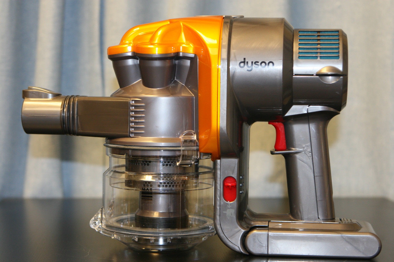
The Dyson DC16 is one of the older handheld vacuums, before the introduction of the “Digital Motor”. (Marketing obviously didn’t think “Switched Reluctance Motor” sounded quite as good).
These vacuums have a very large DC brush motor driving the suction turbine instead, the same as would be found in a cordless power tool.
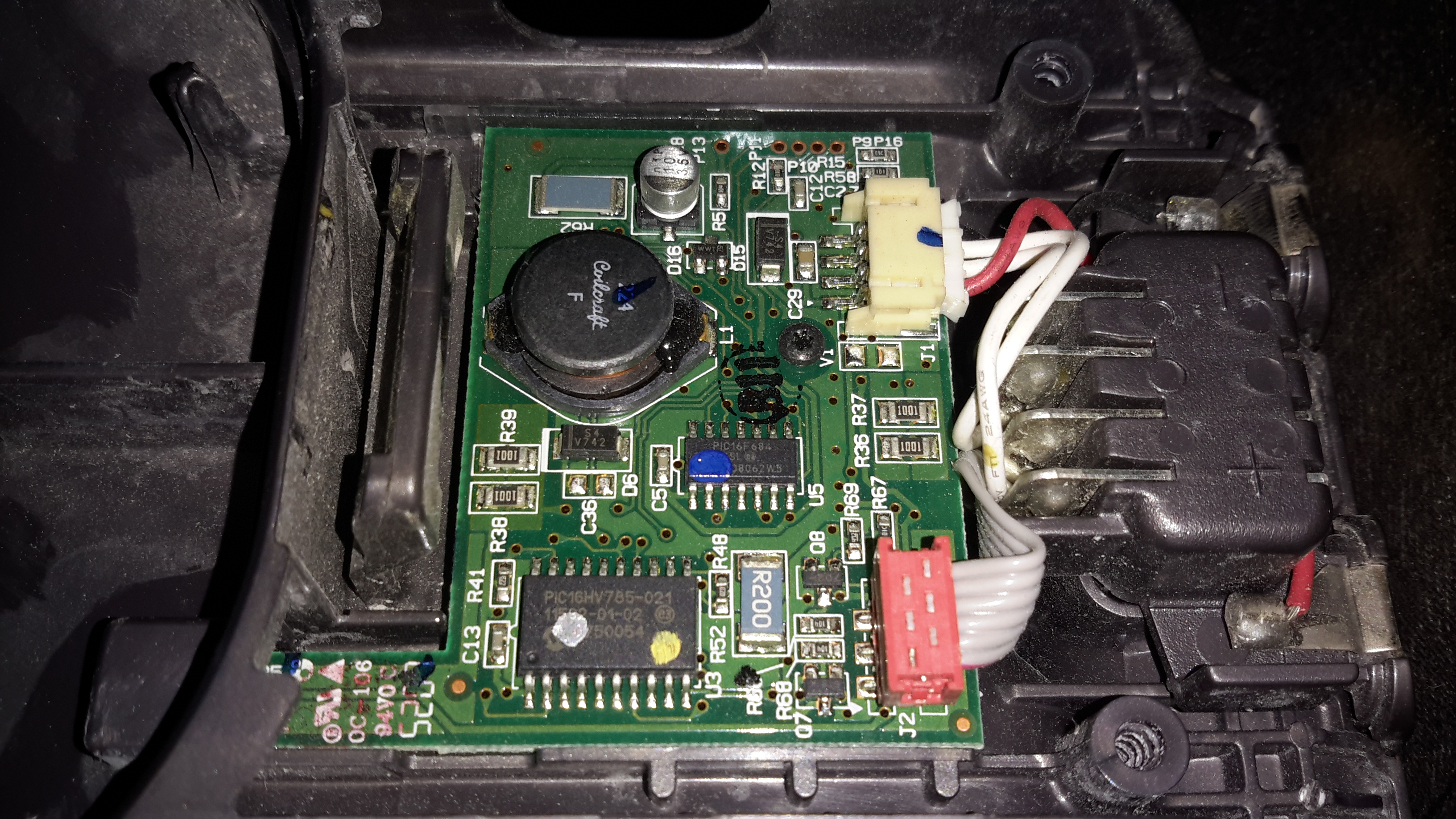
Popping the front cap off with the ID label, reveals the brains of the vacuum. The two large terminals at the right are for charging, which is only done at 550mA (0.5C). There are two PIC microcontrollers in here, along with a large choke, DC-DC converter for supplying the logic most likely. The larger of the MCUs, a PIC16HV785, is probably doing the soft-start PWM on the main motor, the smaller of the two, a PIC16F684 I’m sure is doing battery charging & power management. The motor has a PCB on it’s tail end, with a very large MOSFET, a pair of heavy leads connect directly from the battery connector to the motor.
Just out of sight on the bottom left edge of the board is a Hall Effect Sensor, this detects the presence of the filter by means of a small magnet, the vacuum will not start without a filter fitted.
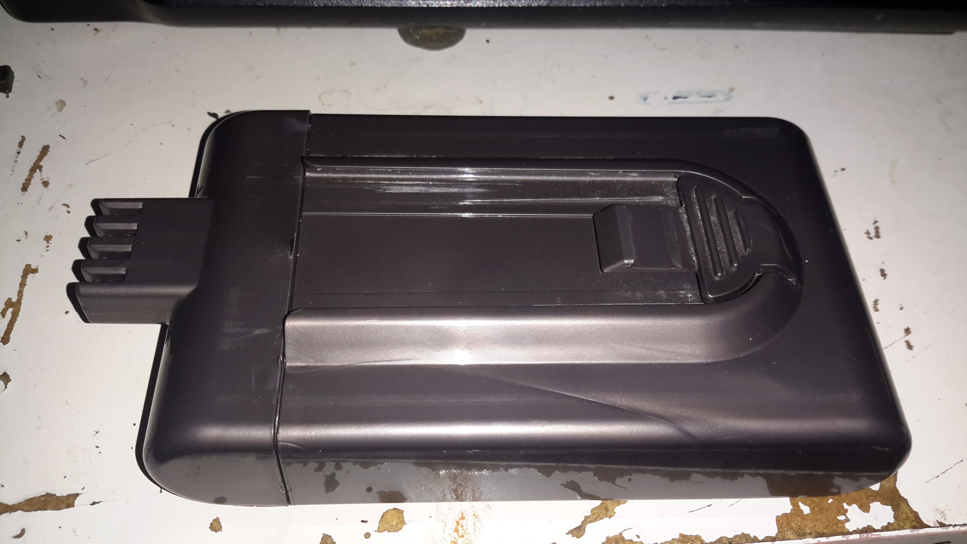
The battery pack is a large custom job, obviously. 4 terminals mean there’s slightly more in here than just the cells.
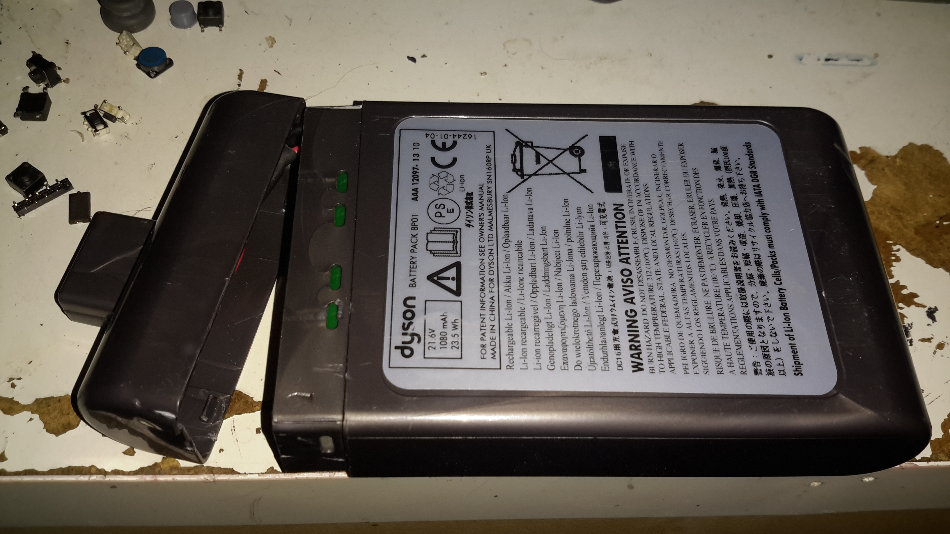
Luckily, instead of ultrasonic or solvent welding the case, these Dyson batteries are just snapped together. Some mild attack with a pair of screwdrivers allows the end cap to be removed with minimal damage.
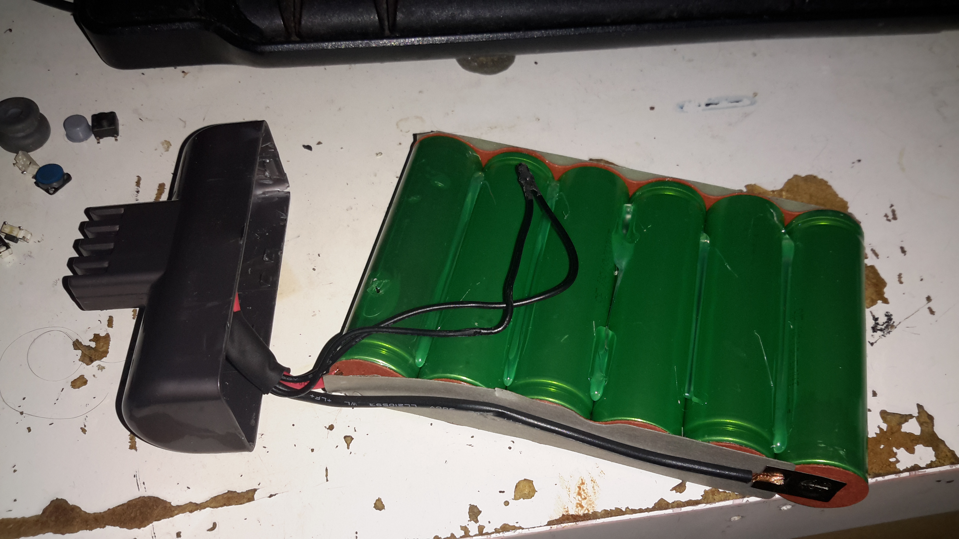
The cells were lightly hot-glued into the shell, but that can easily be solved with a drop of Isopropanol to dissolve the glue bond. The pack itself is made up of 6 Sony US18650VT High-Drain 18650 Li-Ion cells in series for 21.6v nominal. These are rated at a max of 20A discharge current, 10A charge current, and 1.3Ah capacity nominal.
There’s no intelligence in this battery pack, the extra pair of terminals are for a thermistor, so the PIC in the main body knows what temperature the pack is at – it certainly gets warm while in use due to the high current draw.
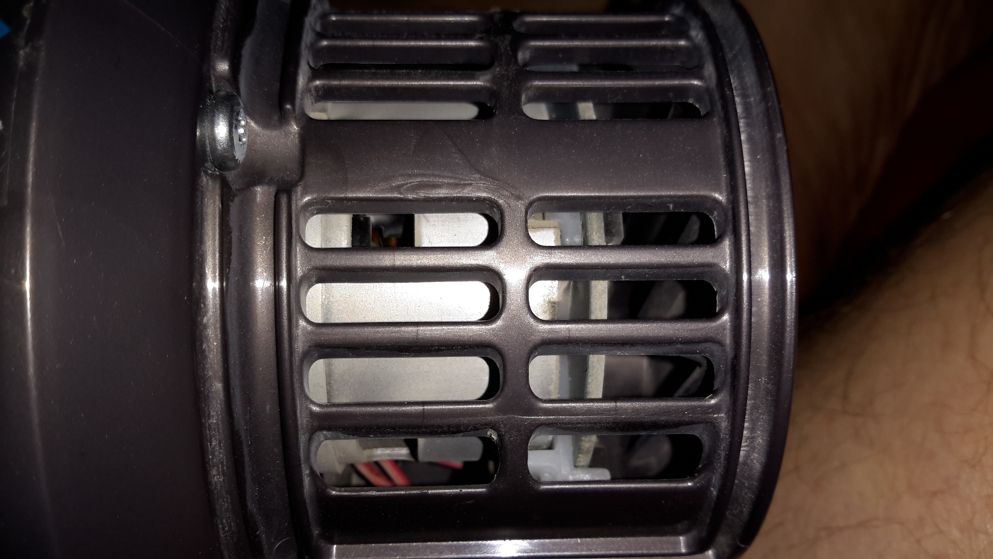
Hidden in the back side of the main body is the motor. Unfortunately I wasn’t able to get this out without doing some damage, as the wiring isn’t long enough to free the unit without some surgery.
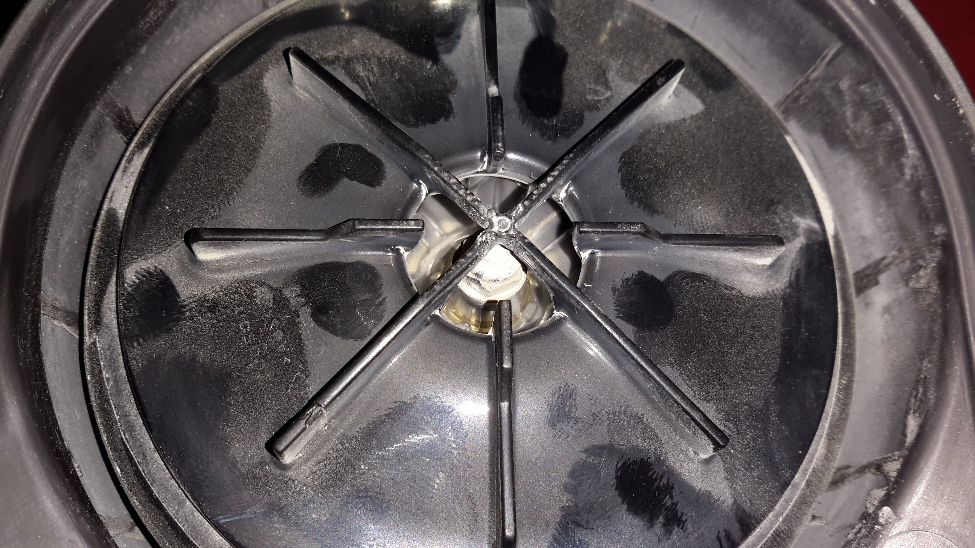
The suction is generated by a smaller version of the centrifugal high-speed blowers used in full size vacuums. Not much to see here.
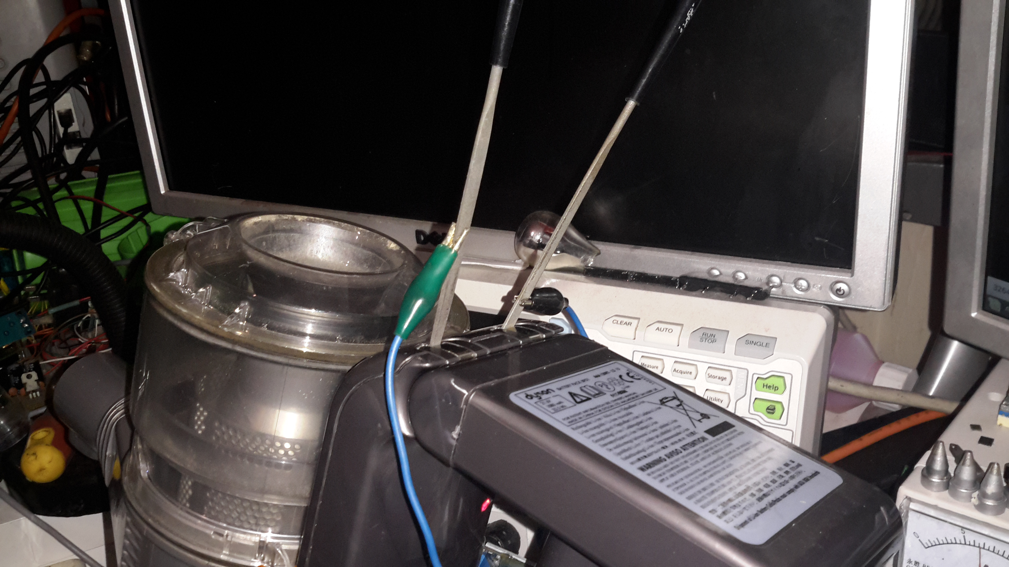
Since I got this without a charger, I had to improvise. The factory power supply is just a 28v power brick, all the charging logic is in the vacuum itself, so I didn’t have to worry about such nasties as over-charging. I have since fitted the battery pack with a standard Li-Po balance cable, so it can be used with my ProCell charger, which will charge the pack in 35 minutes, instead of the 3 hours of the original charger.

Hello, I have the similar problem as my dyson dc16 can’t be charged by the original charger. Can I know which model of Cellpro charger do you use for it? Thanks and regards
Hi Sam,
The charger I use is a Turnigy Accucell 6, has worked fine for my use.
Thanks a lot for your reply! So when you charged the dc16, which battery type do you choose in your Turnigy Accucell 6, Lilon or Lipo? How much is the output voltage and current do you set when charging? Regards
Hi Sam,
I use LiPo mode, 4.2v cutoff, 0.5C charge rate. The low charge rate is easier on the cells.
Thanks for sharing! Try to get one balance charger and test. So I just set the charger in lipo charging model following your setting, and clamp the negative and positive as your last picture shows. Am I right?
Hope it will work for my DC16 too.
Hi Sam,
The battery pack will need a balance connector fitting, this requires disassembly of the battery casing. (The Turnigy chargers will not charge a multi-cell pack without a balance connector). If you are not familiar with this process I’d recommend you read up on it, soldering to a live battery pack can be risky.
As mentioned in my post, skewering the factory charging terminals with something to charge from a 28v power supply also works fine, as the charging logic in this Dyson is inside the vacuum, not the wall-wart. It’s just much slower this way.
Cheers
Thanks for your clear explanation! It is very helpful to me. I am not familiar with the first way. The second way is better for me. Will try to find a 28v power supply.
But I still have a question. Whether the current need to be 400mA as Dyson charger when I use 28v power supply, or the current can be high like 1A or more?
Kind regards
Hi Sam,
Current rating doesn’t matter, as long as it’s equal or above the rating of the original supply. The vacuum will only pull as much current from the supply as it needs to charge the battery.
Got it, thank you so much for all your reply and explanation! Cheers!
reading up your saying you use the lipo mode to charge but these are nimh batteries? shouldnt you use that nimh and a low charge? no need for ballance leads either? sorry just bit confused as i fly models and use lipo and nimh batteries hense my confusion here
Hi niskhawolf,
The cells in these dyson packs are Sony US18650VT lithium cells, not Ni-MH. See the photos in the post :).
I haven’t seen one of these with Ni-MH cells before, they were used along with Ni-Cd cells in in the older handheld vacuums.
Hi. It doesn’t sound as though the motor is particularly sophisticated. My DC16 charges OK and the battery is good. However, it cuts out after about 3-4 seconds of running (most of the time – occasionally it runs longer, but that’s not predictable). The speed of the motor doesn’t fall off as it would if the battery was dying, so I suspect the EPROM is playing up. The Hall Effect sensor has been removed (before I got it) and that hasn’t fixed the problem, and I see others on the net complaining of the same symptom. Dyson just tell you they don’t supply spares any more, which is disappointing when it was quite expensive and it hasn’t had that much use.
I had hoped to be able to swap the circuit board for the later model, but if as you say they’ve changed the motor what wouldn’t work. So, is there any way that I can frig the circuit board to stop the motor cutting out? In principle, you’d think it should just require a straight go/stop option, but I need to keep battery charging circuit operational.
Thanks
Hi Coxy,
The motor in these vacuums is indeed simple – it’s a 24v DC permanent magnet motor. Bypassing the main circuitry of the vacuum in this case would be relatively easy.
A simple MOSFET switch or relay wired into the trigger switch to control the power to the main motor would do the job fine, with a small amount of rewiring.
This would leave the battery charging logic in place, but just bypass the other functions.
The only issue would be that the vacuum would lose it’s undervoltage lockout protection, and the battery could be damaged by operating the vacuum for too long. Recharging such a battery would be risky.
So, could I retrofit a power tool battery for use with this? I found an old one of these that I never got around to replacing the battery on.
As a test run I tried connecting two twelve volt lawnmower type battery’s connected for 24 volts. I popped out two terminals on the battery connection(not the charging leads). I left the two temp connectors empty. It didn’t work. Do I need to feed it a nominal voltage to imitate the temp input?
Any… most input is welcome lol