I recently used a Vishay Spectrol Precision 10-turn potentiometer in my latest PSU project, and since these clip together instead of being ultrasonically welded like Bourns potentiometers, I decided to do a quick teardown for the blog. I didn’t find much in the way of how these pots worked from a search, so here we go!
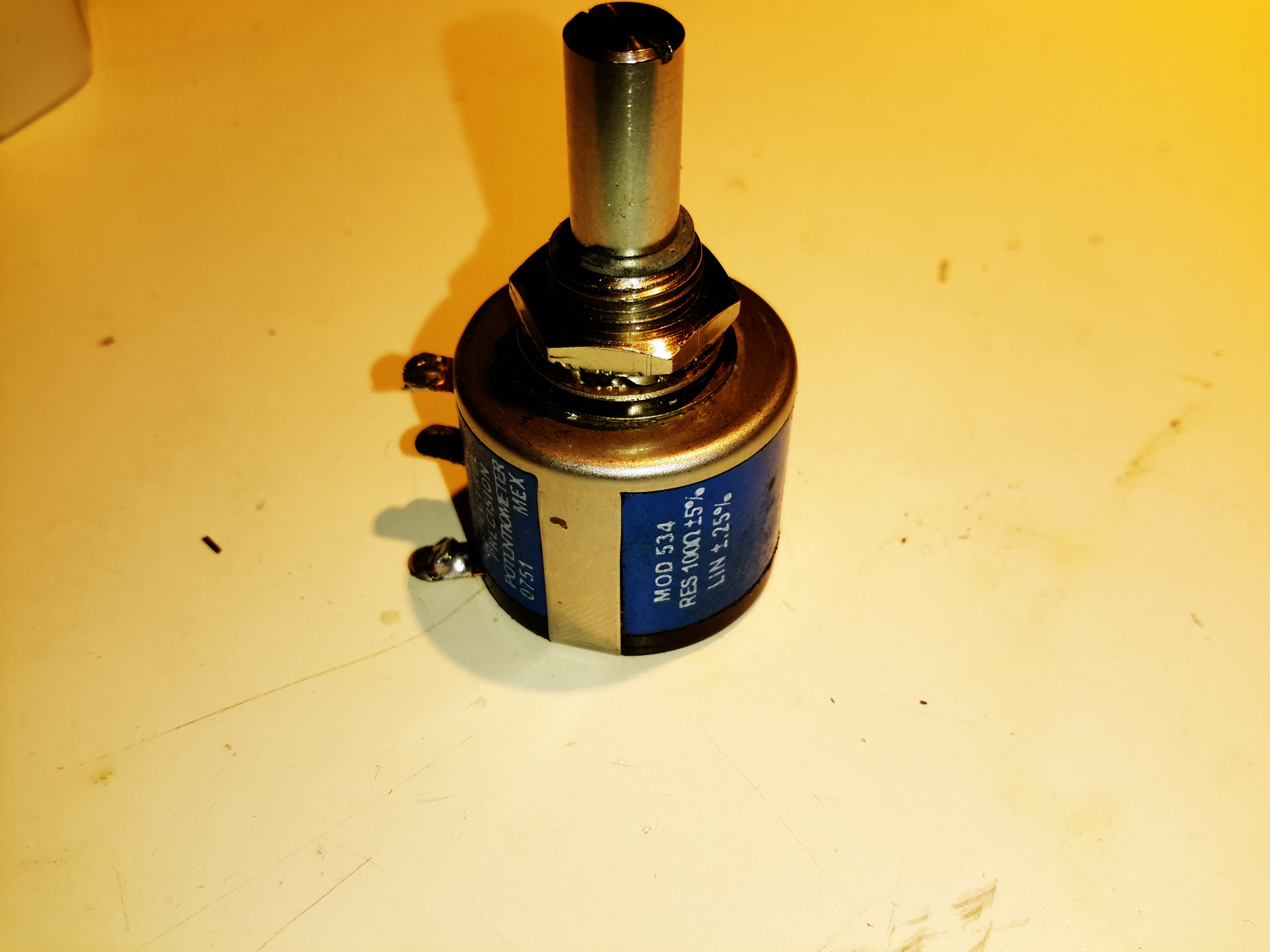
Vishay Spectrol Precision 10-Turn
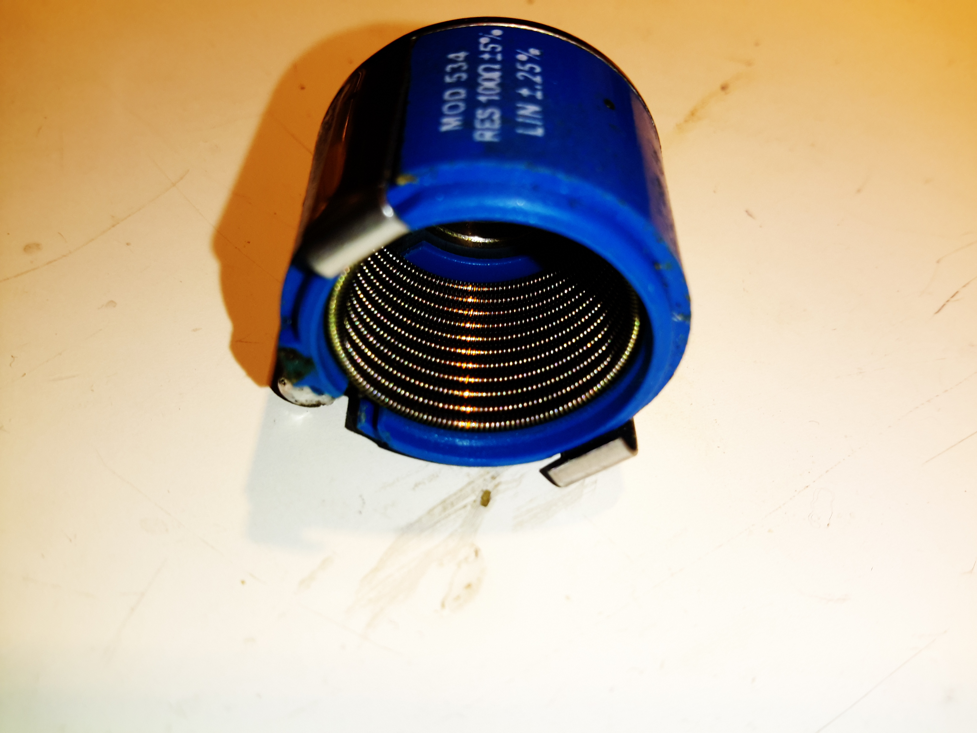
Here’s a pot of the same spec as I used in the previous project, again from my random used junk bin. This is a 100Ω, 5% wirewound potentiometer. The shaft is secured in the centre bushing with a snap ring, this is easily removed with a pair of needlenose pliers.
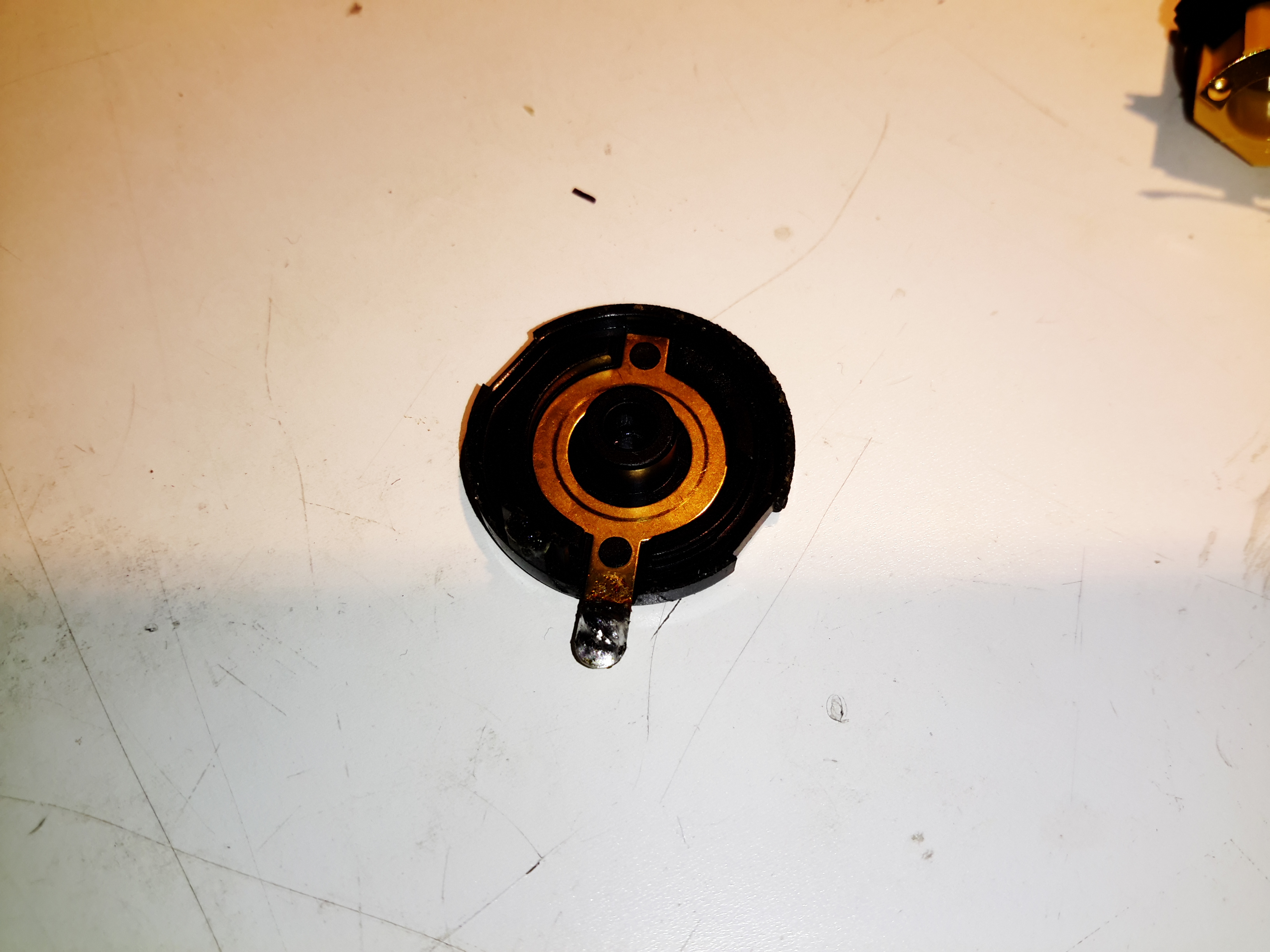
Wiper Stationary Contact
After unclipping the back cover, the stationary part of the wiper contact is visible in the back plastic cover.
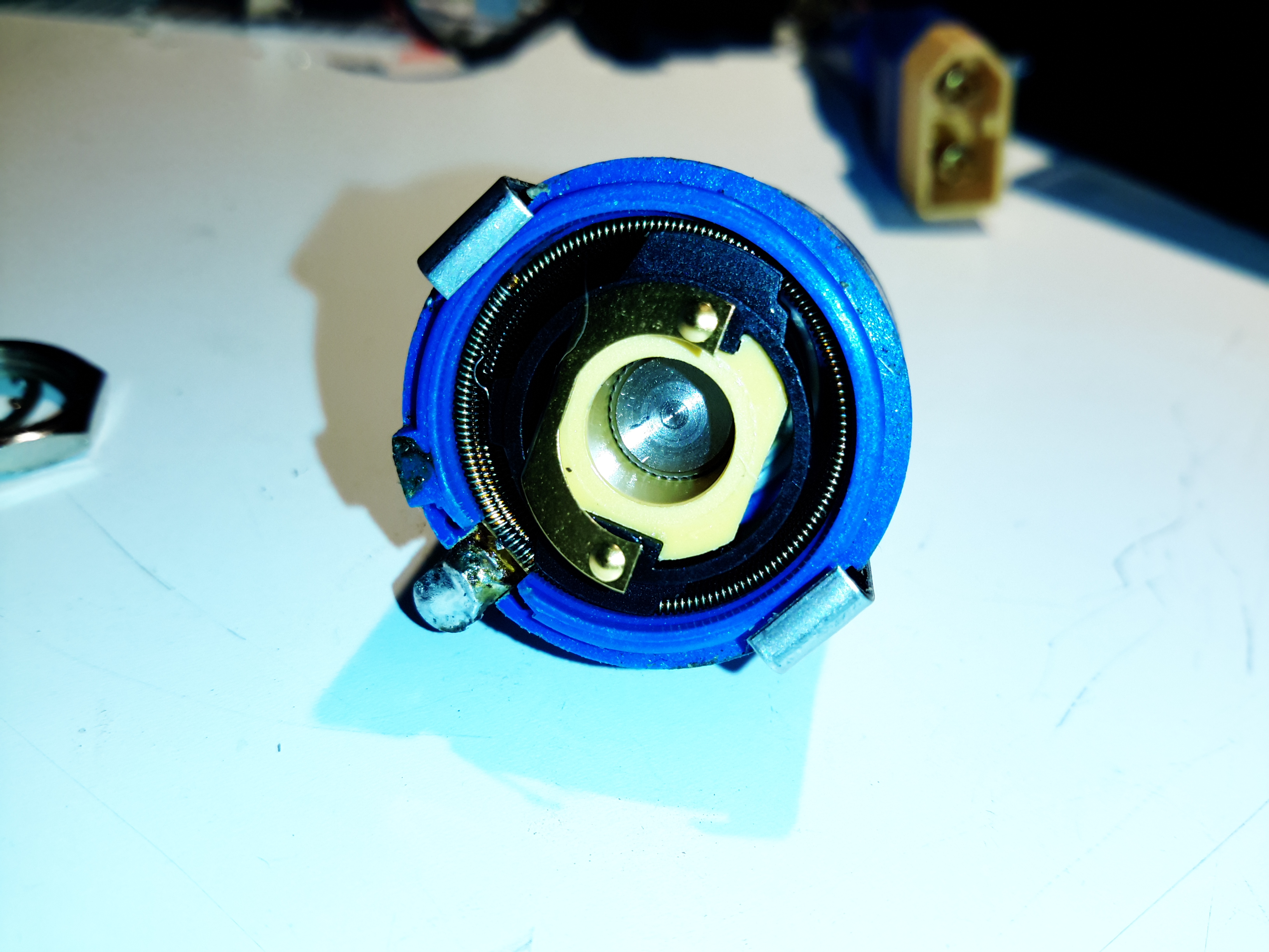
Back Cover Removed
Inside the back of the potentiometer shows the inner workings. These devices have a large helical winding of resistance wire around the inner diameter of the casing, the wiper tracks this helix as the potentiometer is turned.
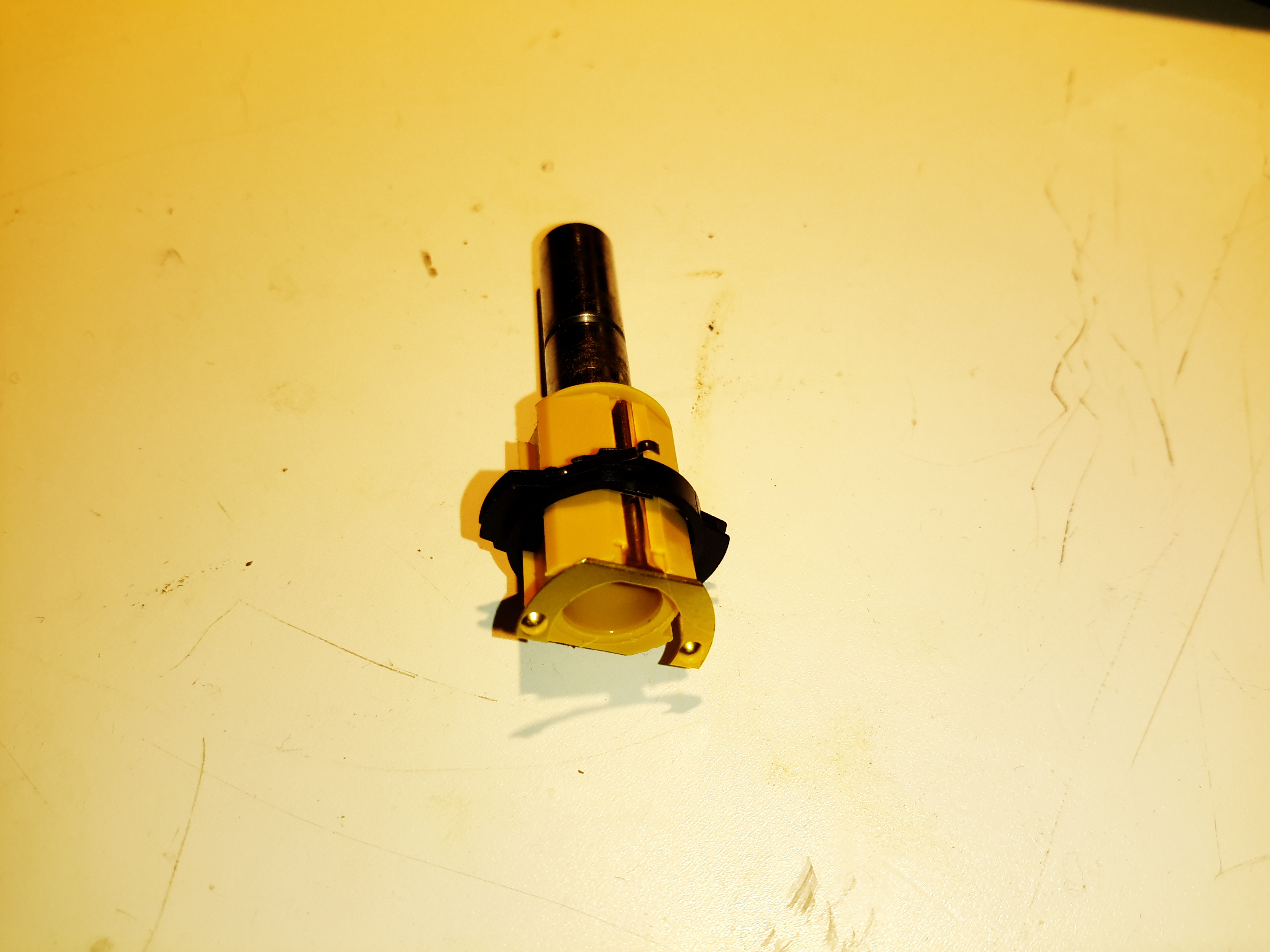
Centre Contact & Shaft
As the wiper must move axially as it winds around the spiral of resistance wire, the contact is mounted on a pair of guides so it can slide back & forth. The electrical connection is made via another spring contact that runs down the side of the plastic shaft insert. Two notches cut into the black plastic wiper frame engage with the round profile of the resistance winding like a screw into a nut, keeping the wiper in perfect alignment as it travels the full length of the winding. I suspect all these moving contacts are made of Beryllium Copper in this rather expensive component as this alloy is very flexible, as well as being a very good electrical conductor.
Resistance Winding
With the centre shaft & it’s wiper contact removed from the shell, the helix of resistance wire can be seen inside. Oddly, the former the resistance wire is wound around appears to be metal, possibly copper, but to keep the entire thing from shorting itself out this must be coated in insulation.
Since I’ve discovered some nice high power PSUs in the form of Playstation 3 PSUs, it’s time to get a new Bench PSU Build underway!
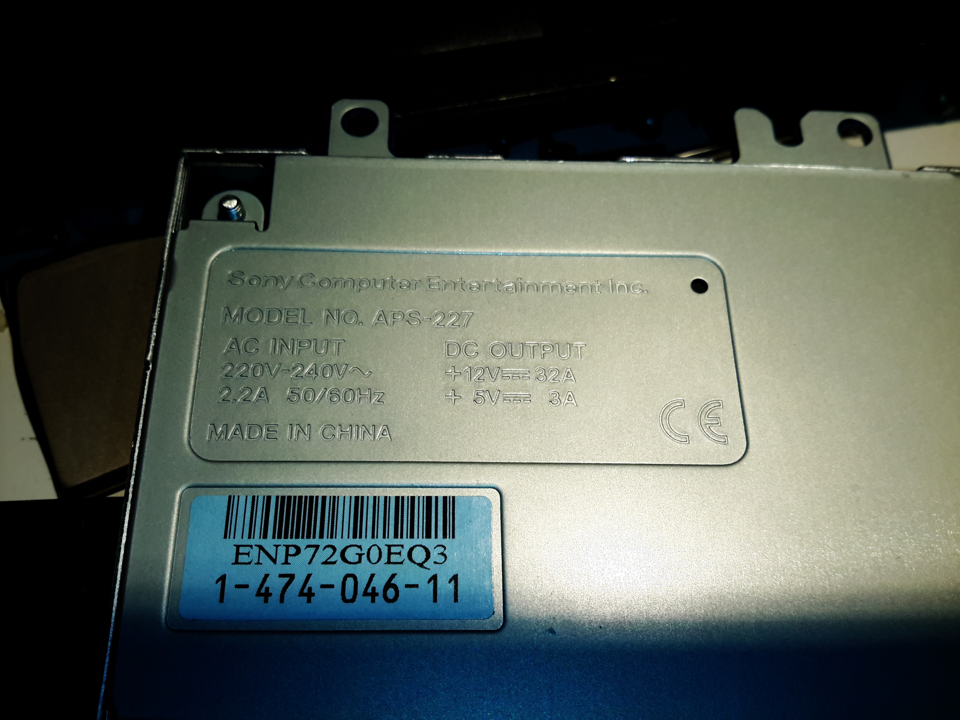
Specifications
I’ve gone for the APS-227 version as it’s got the 32A rail. This makes things slightly beefier overall, as the loading will never be anywhere close to 100% for long, more headroom on the specs is the result.
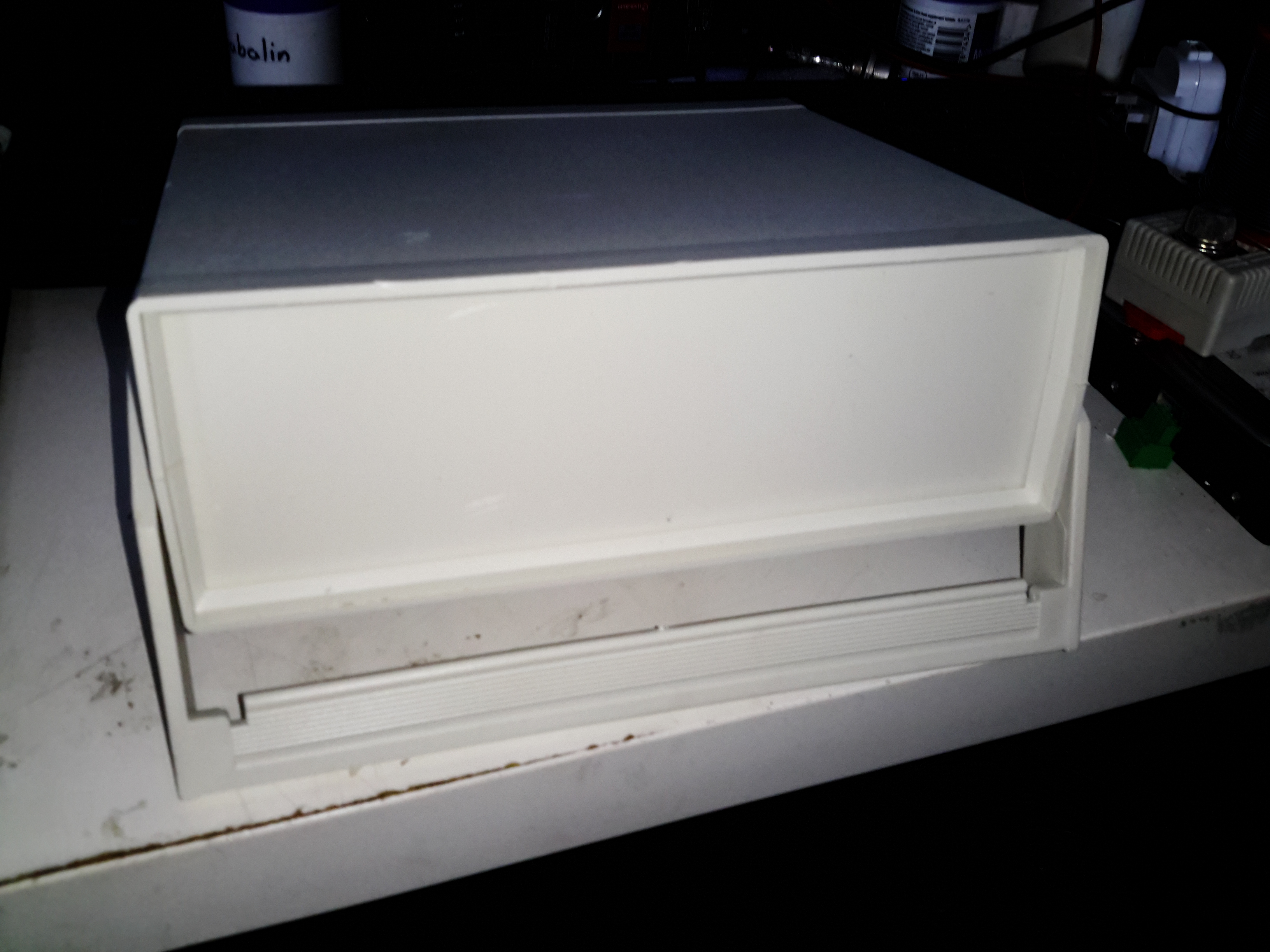
Desktop Instrument Case
The case I’ve chosen for this is an ABS desktop instrument case from eBay, the TE554 200x175x70mm. The ABS is easy to cut the holes for all the through-panel gear, along with being sturdy enough. Aluminium front & back panels would be a nice addition for a better look.
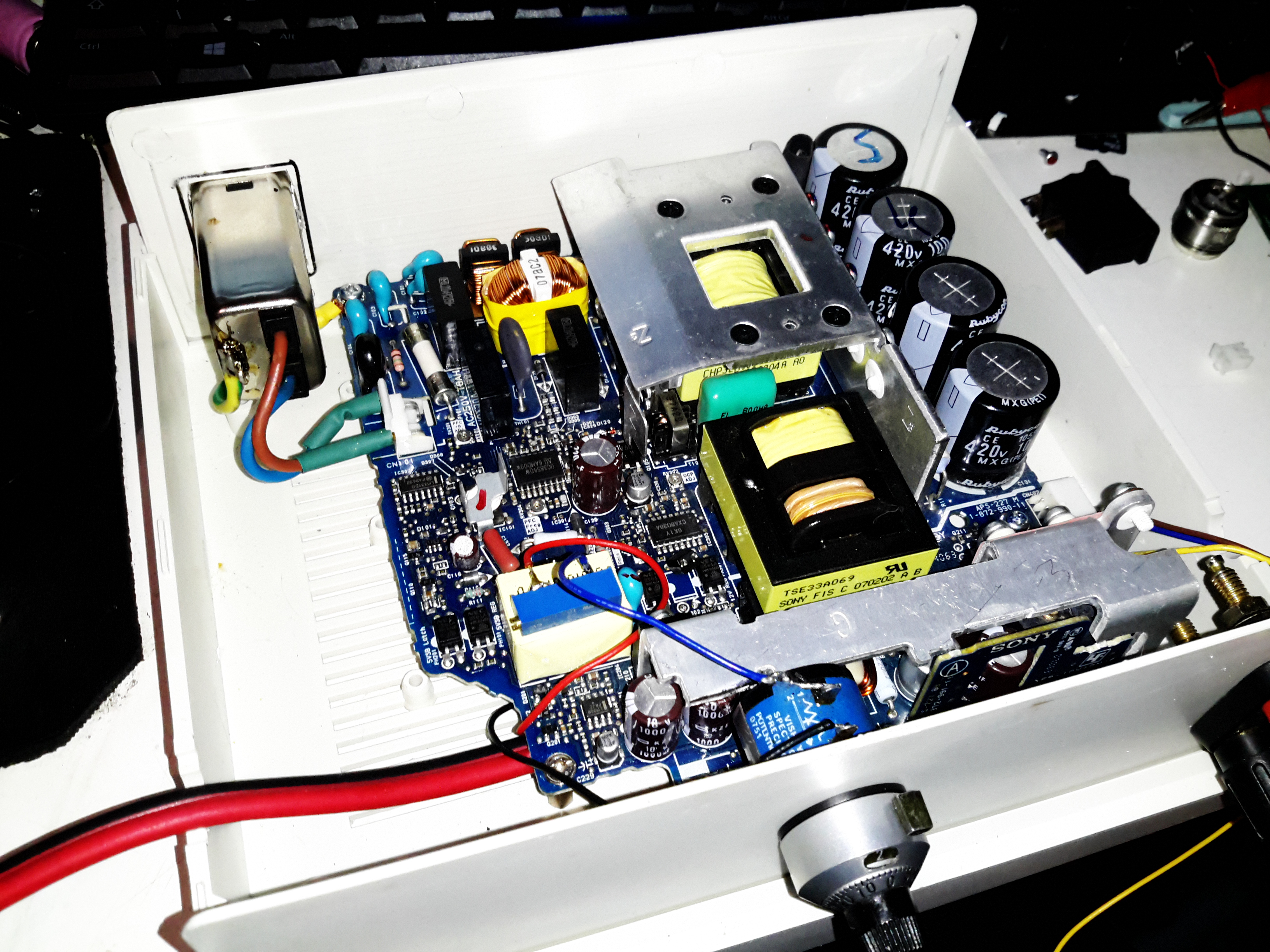
PSU Mounted
The PSU board is removed from it’s factory casing & installed on the bottom shell half, unfortunately the moulded-in posts didn’t match the screw hole locations so I had to mount some brass standoffs separately. The AC input is also fitted here, I’ve used a common-mode filter to test things (this won’t be staying, as it fouls one of the case screw holes). The 40A rated DC output cable is soldered directly to the PCB traces, as there’s no room under the board to fit the factory DC power connector. (This is the biggest case I could find on eBay, and things are still a little tight). Some minor modifications were required to get the PCB to fit correctly.
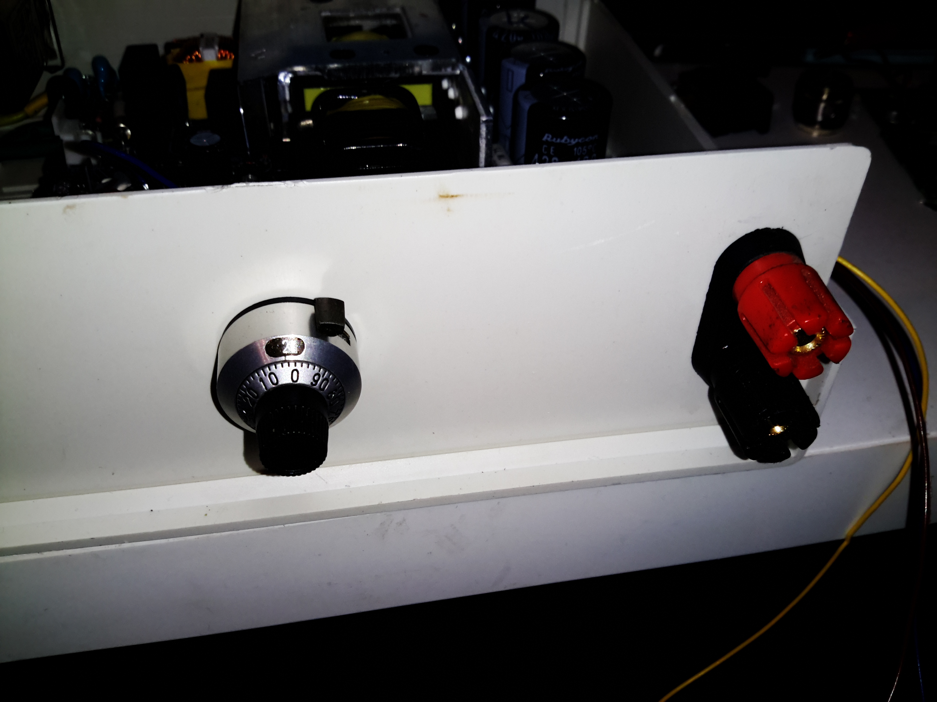
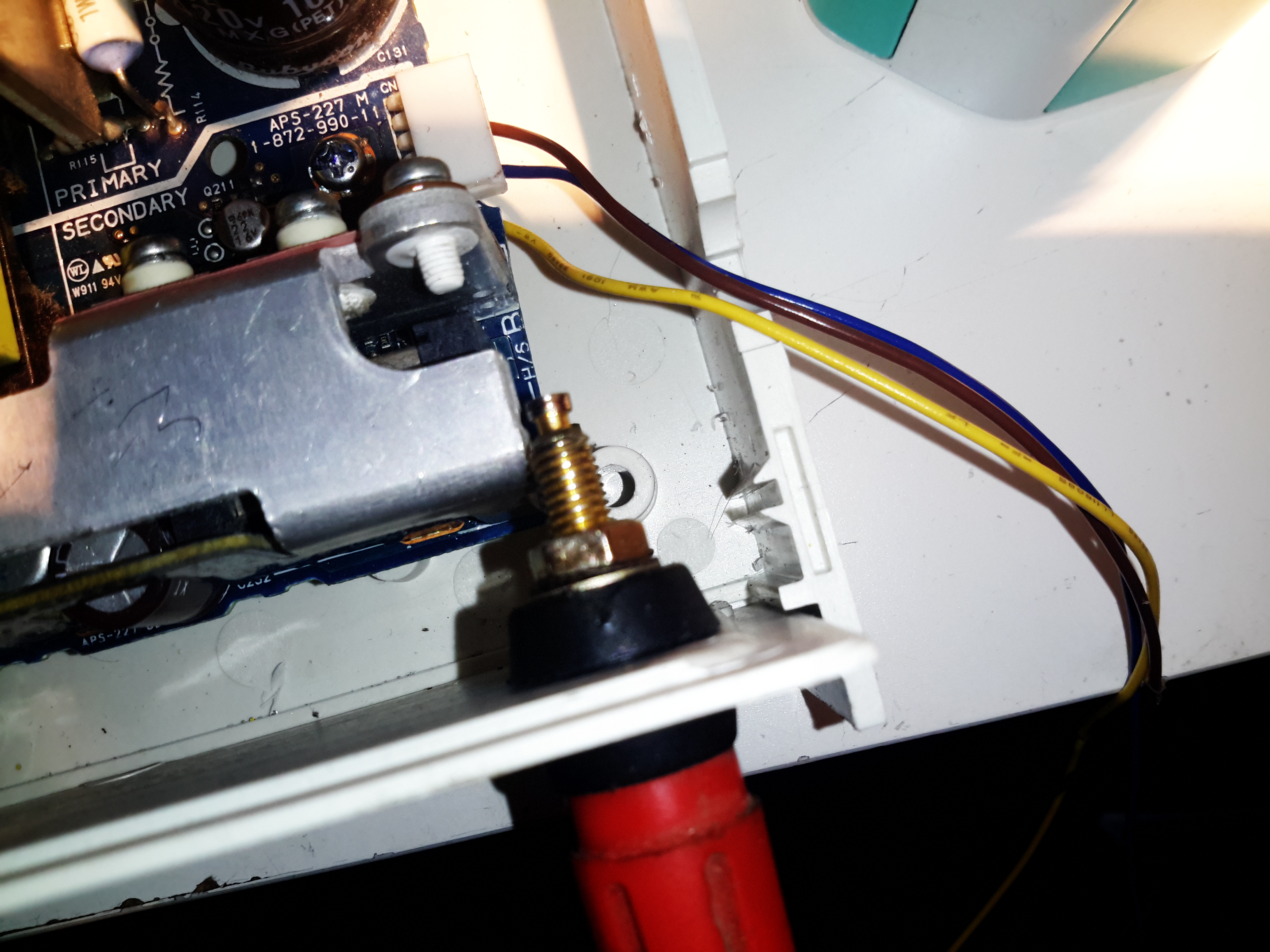
Output Terminals & Adjuster
I decided to add some limited voltage adjustment capability to the front panel, I had a 100Ω Vishay Spectrol Precision 10-turn potentiometer in my parts bin, from a project long since gone that just about fits between the panel & the output rectifier heatsink. The trimpot I added when I first posted about these PSUs is now used to set the upper voltage limit of 15 volts. (The output electrolytics are 16v rated, and are in an awkward place to get at to change for higher voltage parts). The binding posts are rated to 30A, and were also left over from a previous project.
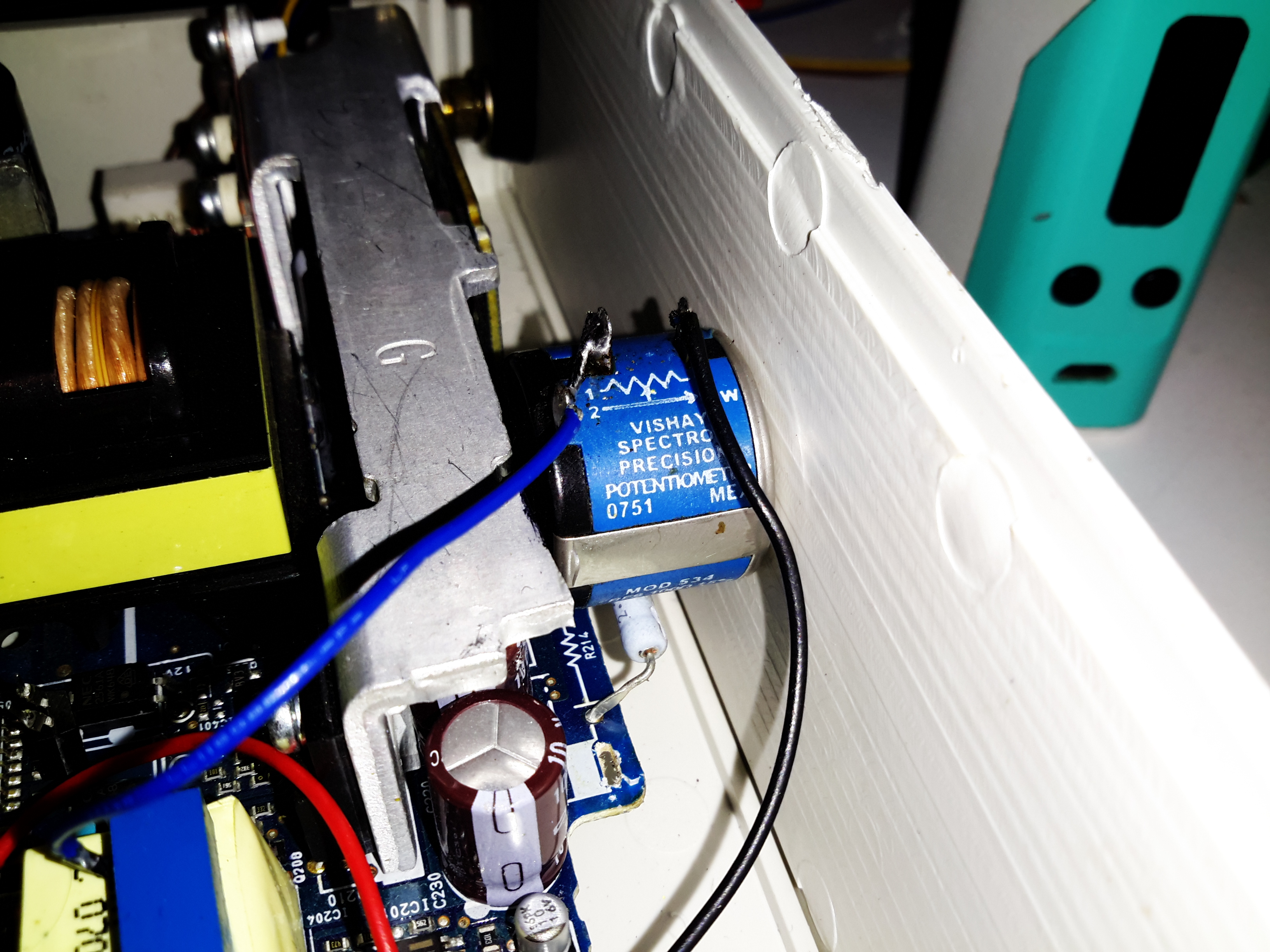
Vishay Spectrol 10-Turn
Addon Regulator Components
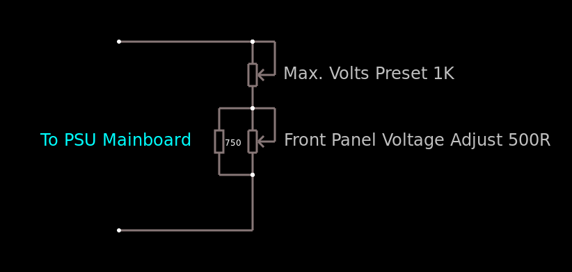
This front panel potentiometer is electrically in series with the trimpot glued to the top of the auxiliary transformer, see above for a simple schematic of the added components. In this PSU, reducing the total resistance in the regulator circuit increases the voltage, so make sure the potentiometer is wired correctly for this!
After some experimentation, a 500Ω 10-turn potentiometer would be a better match, with a 750Ω resistor in parallel to give a total resistance range on the front panel pot of 300Ω. This will give a lower minimum voltage limit of about 12.00v to make lead-acid battery charging easier.
I’ve had to make a minor modification to the output rectifier heatsink to get this pot to fit in the available space, but nothing big enough to stop the heatsink working correctly.
Terminal Posts
Here I’ve got the binding posts mounted, however the studs are a little too long. Once the wiring is installed these will be trimmed back to clear both the case screw path & the heatsink. (The heatsink isn’t a part of the power path anyway, so it’s isolated).
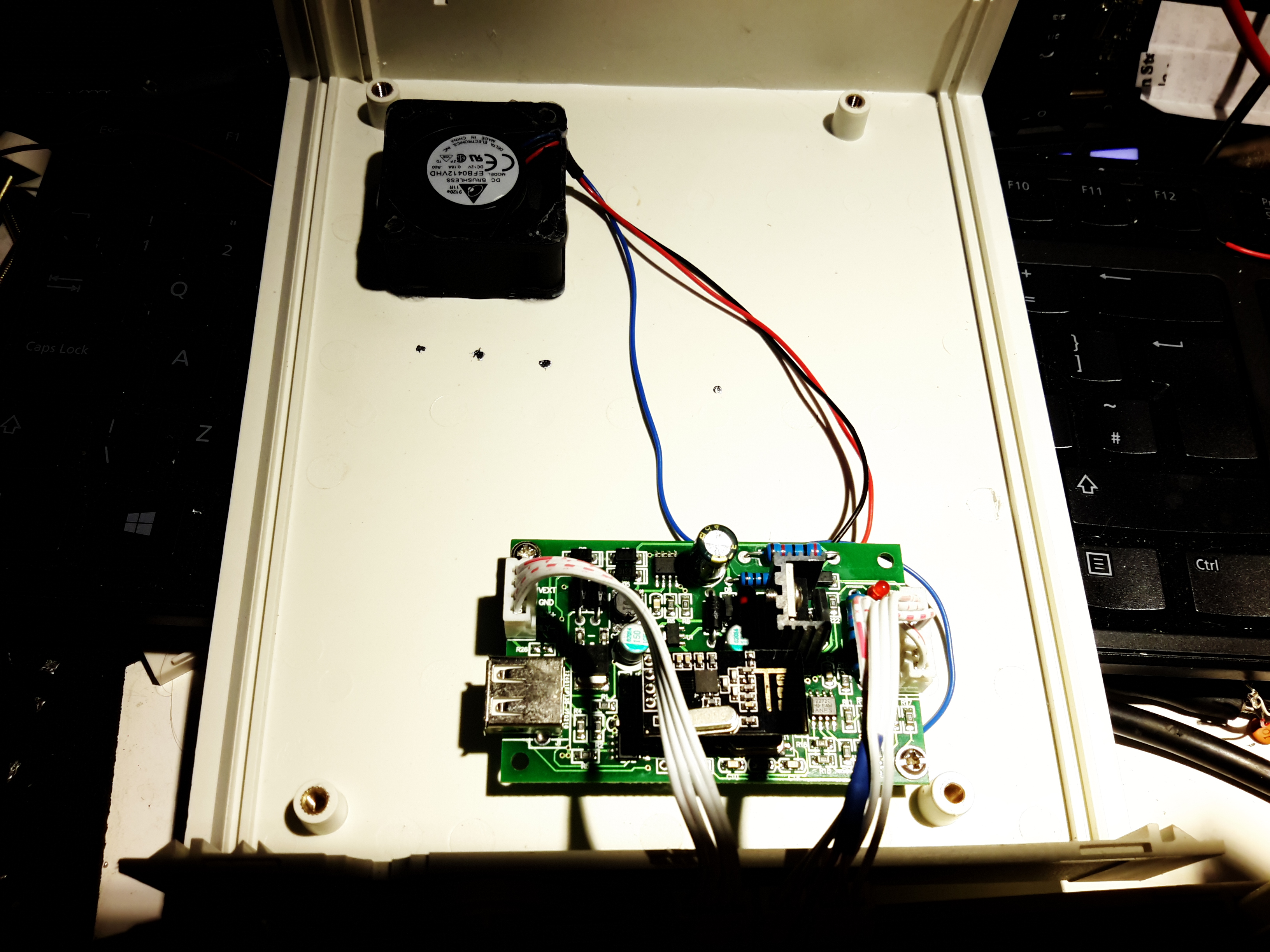
Power Meter Control Board & Fan
To keep the output rectifier MOSFETs cool, there’s a fan mounted in the upper shell just above their location, this case has vents in the bottom already moulded in for the air to exit. The fan is operated with the DC output contactor, only running when the main DC is switched on. This keeps the noise to a minimum when the supply doesn’t require cooling. The panel meter control board is also mounted up here, in the only empty space available. The panel meter module itself is a VAC-1030A from MingHe.
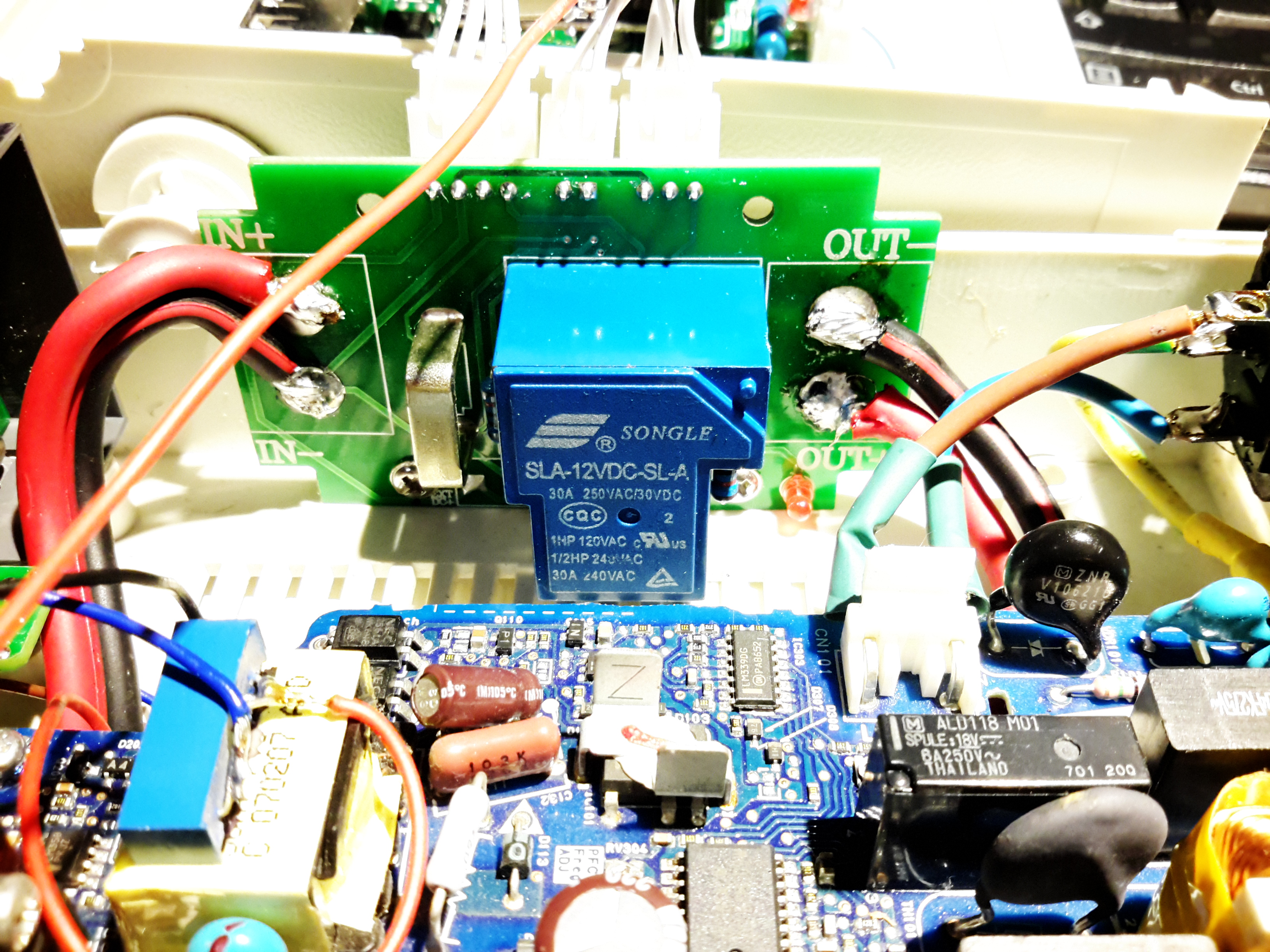
Meter Power Board
The measurement shunt & main power contactor for the DC output is on another board, here mounted on the left side of the case. The measurement shunt is a low-cost one in this module, I doubt it’s made of the usual materials of Manganin or Constantan, this is confirmed by my meansurements as when the shunt heats up from high-power use, the readings drift by about 100mA. The original terminal blocks this module arrived with have been removed & the DC cables soldered directly to the PCB, to keep the number of high-current junctions to a minimum. This should ensure the lowest possible losses from resistive heating.
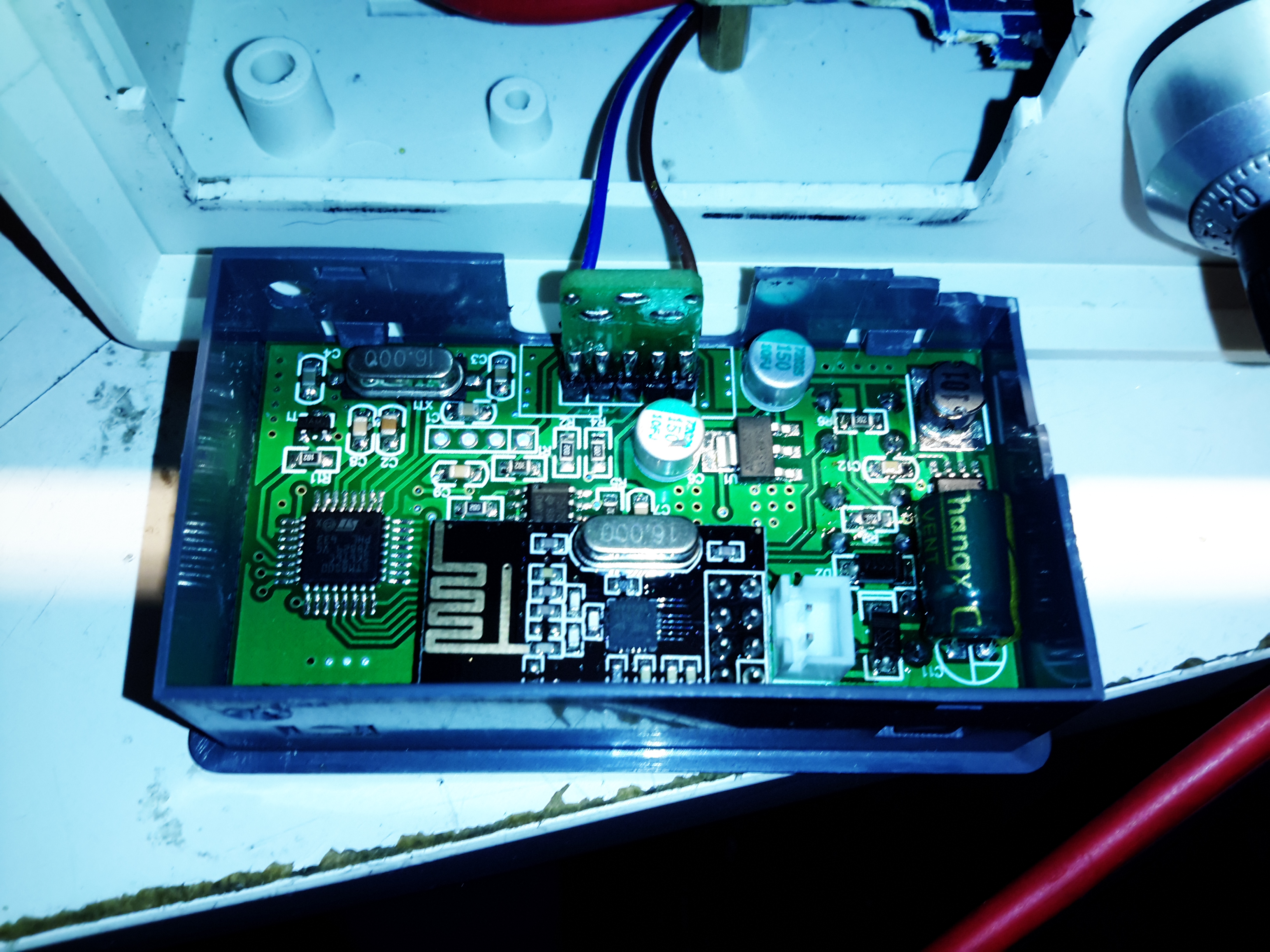
Meter Panel Module
The panel meter module iself is powered from the 5v standby rail of the Sony PSU, instead of the 12v rail. This allows me to keep the meter on while the main 12v output is switched off.
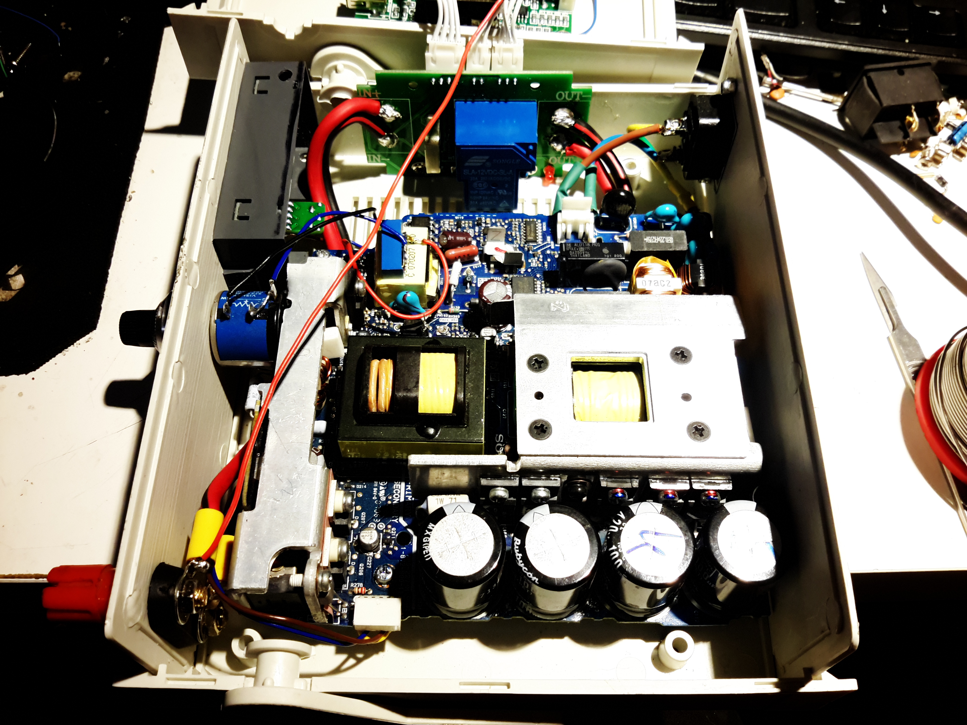
PSU Internals
here’s the supply with everything fitted to the lower shell – it’s a tight fit! A standard IEC connector has been fitted into the back panel for the mains input, giving much more clearance for the AC side of things.
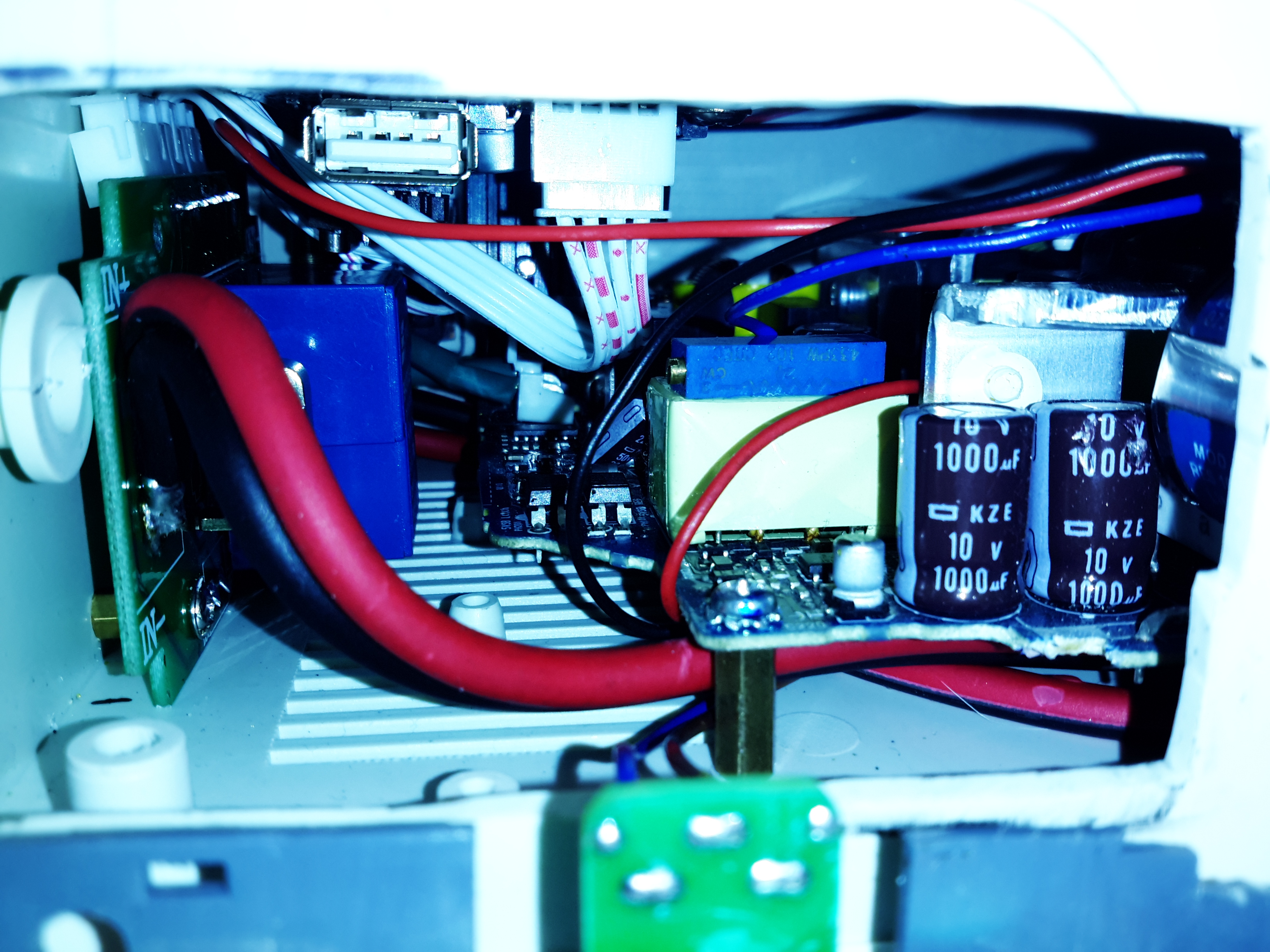
Inside View
With the top shell in place, a look through the panel cutout for the meter LCD shows the rather tight fit of all the meter components. There’s about 25mm of clearance above the top of the PSU board, giving plenty of room for the 40mm cooling fan to circulate air around.
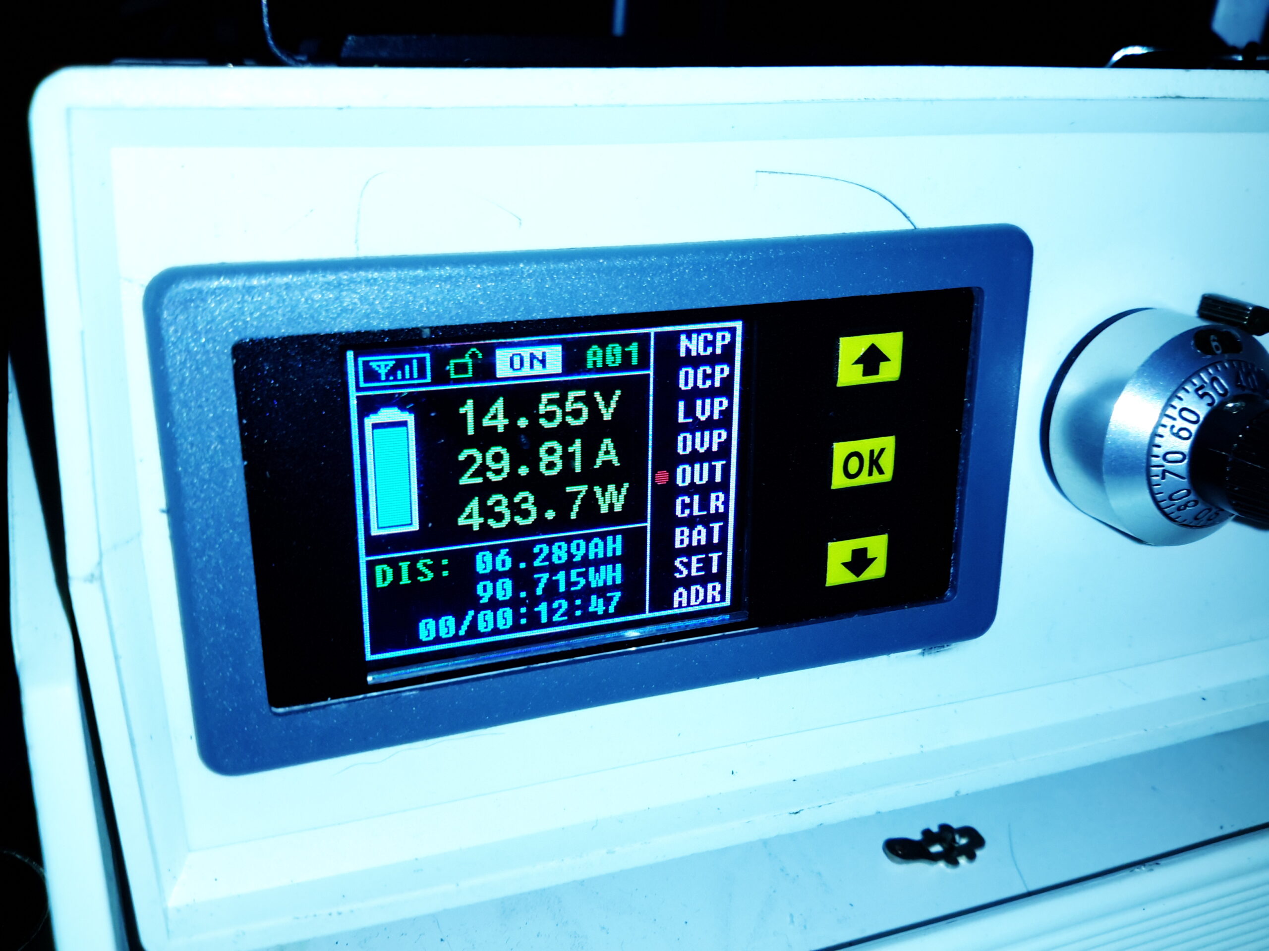
Load Test
Here’s the finished supply under a full load test – it’s charging a 200Ah deep cycle battery. The meter offers many protection modes, so I’ve set the current limit at 30A – preventing Sony’s built in over current protection on the PSU tripping with this function is a bonus, as the supply takes a good 90 seconds to recover afterwards. I’ll go into the many modes & features of this meter in another post.
Here’s the CRT circuitry from a tossed STVG-502 Karaoke Machine, which got a good soaking in Manchester’s brilliantly wet weather before I managed to get hold of it:
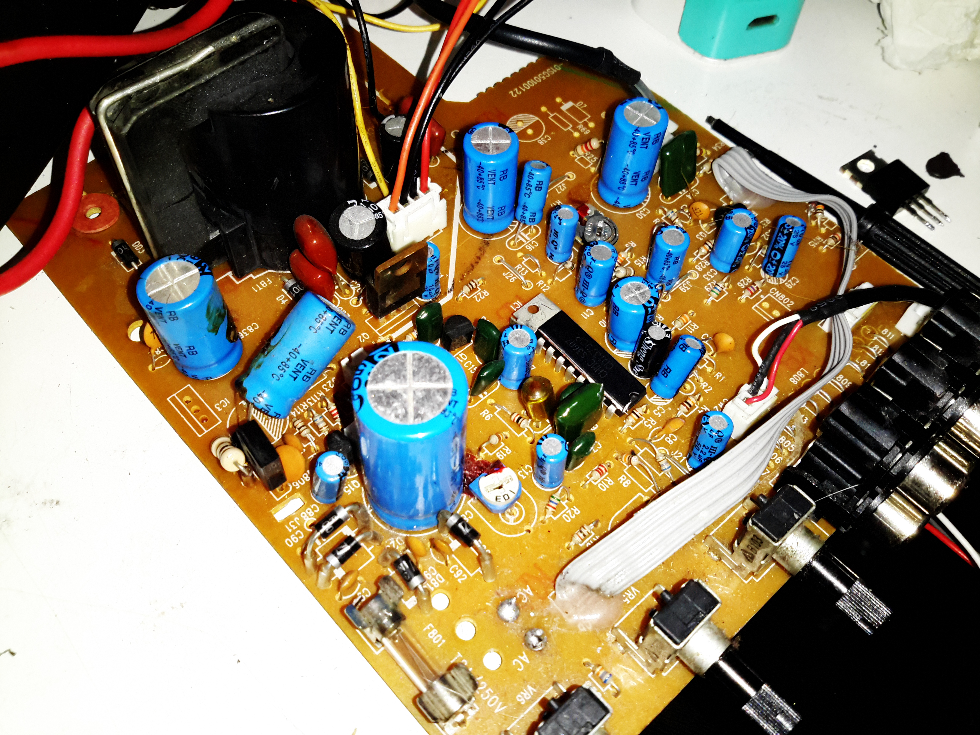
Main PCB
I didn’t do a full teardown of this unit, since it was soaking wet & smelled rather badly of sour milk, so instead I quickly gutted it for the useful parts. These machines are a combination of a CD+G player, CRT composite monitor for displaying the CD+G lyrics & a small audio amplifier & 3W speaker. Power is provided from the mains via a transformer, with both 12 & 24v windings. One half of the board has the audio amplifier sections, the other the CRT drive, running from the 12v & 24v supplies respectively. I chopped off the audio section, as that wasn’t needed.
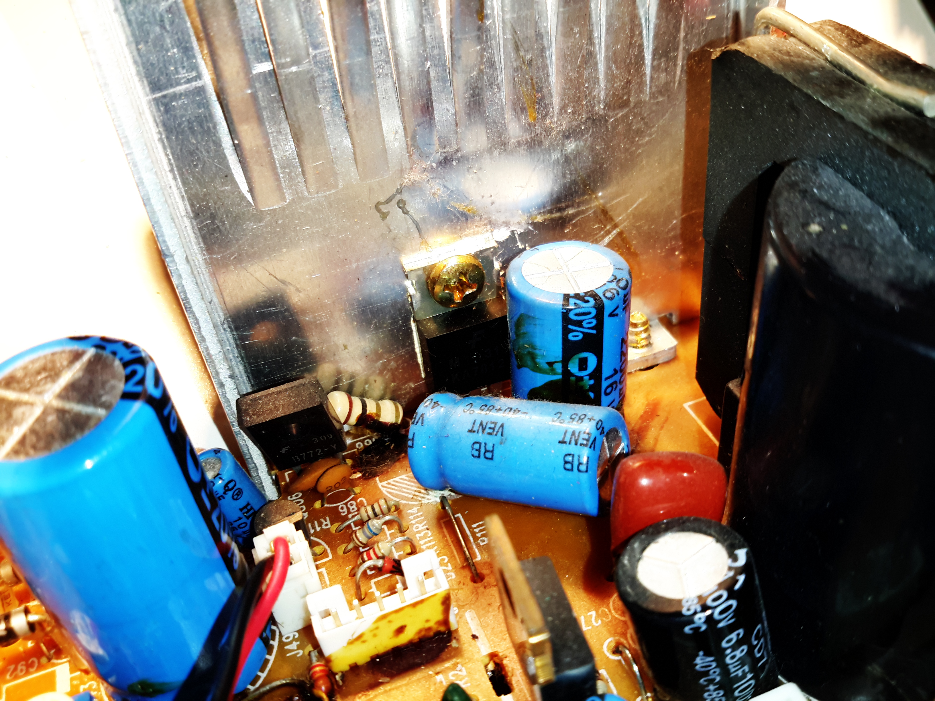
Linear Regulator
On this huge heatsink is what I originally thought was the horizontal drive transistor is actually a 12v linear regulator – the board gets fed 16v AC. This is then run through a rectifier which will produce an approx 22v rail, and after the smaller transistor on the left used for power switching. The 22v then gets dropped through a 1/2W 1Ω resistor, then the linear regulator drops it down to 12v for the rest of the circuit – dissipating a goodly amount of power in the process.
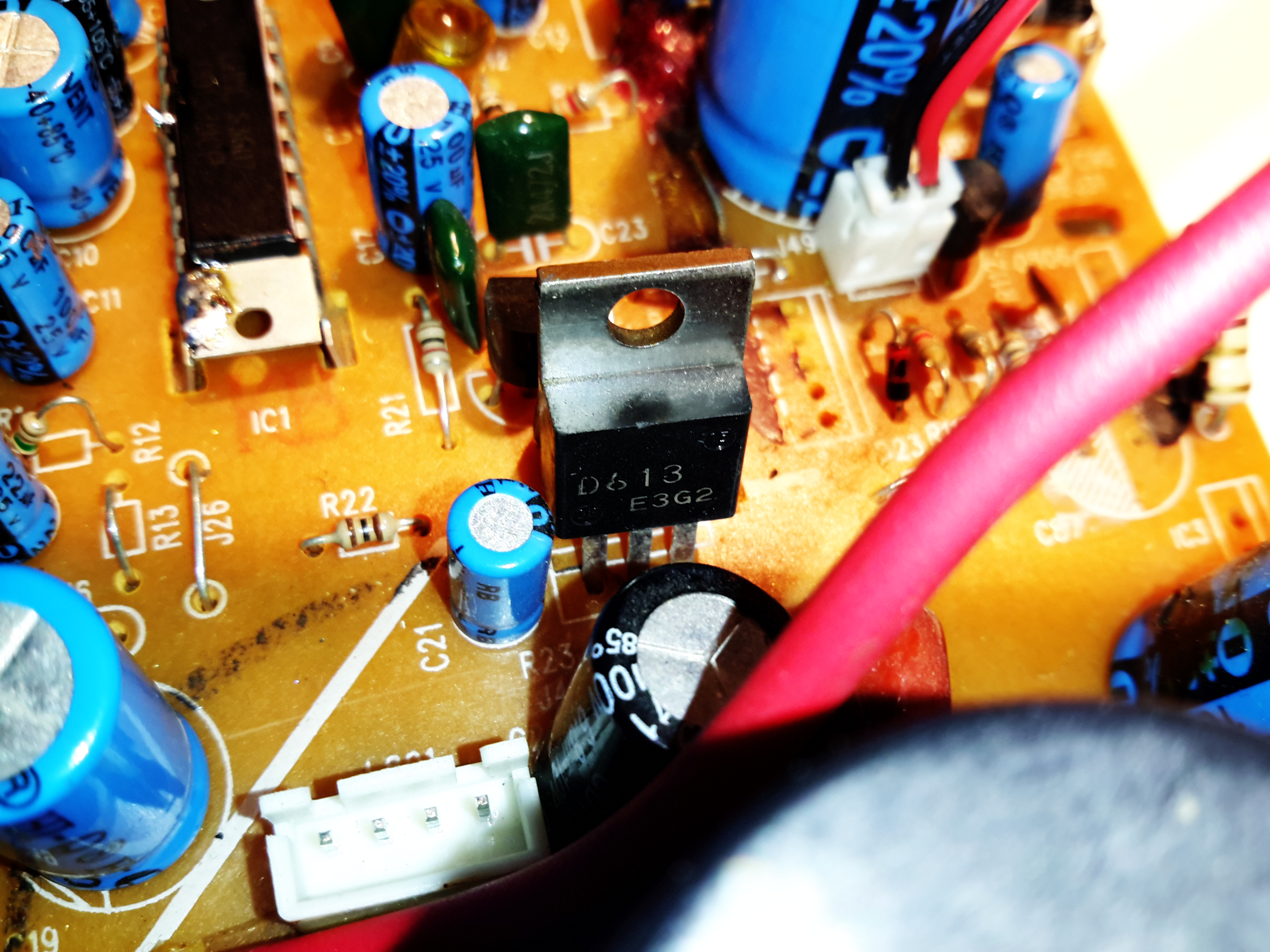
Horizontal Output Transistor
This is in fact the horizontal drive transistor, a 2SD613, which according to the datasheet, is intended for audio amplifier output stage applications, not CRT drive. Regardless, it’s an 85v 6A NPN transistor, and does get a bit on the warm side, but was never given a heatsink from the factory.
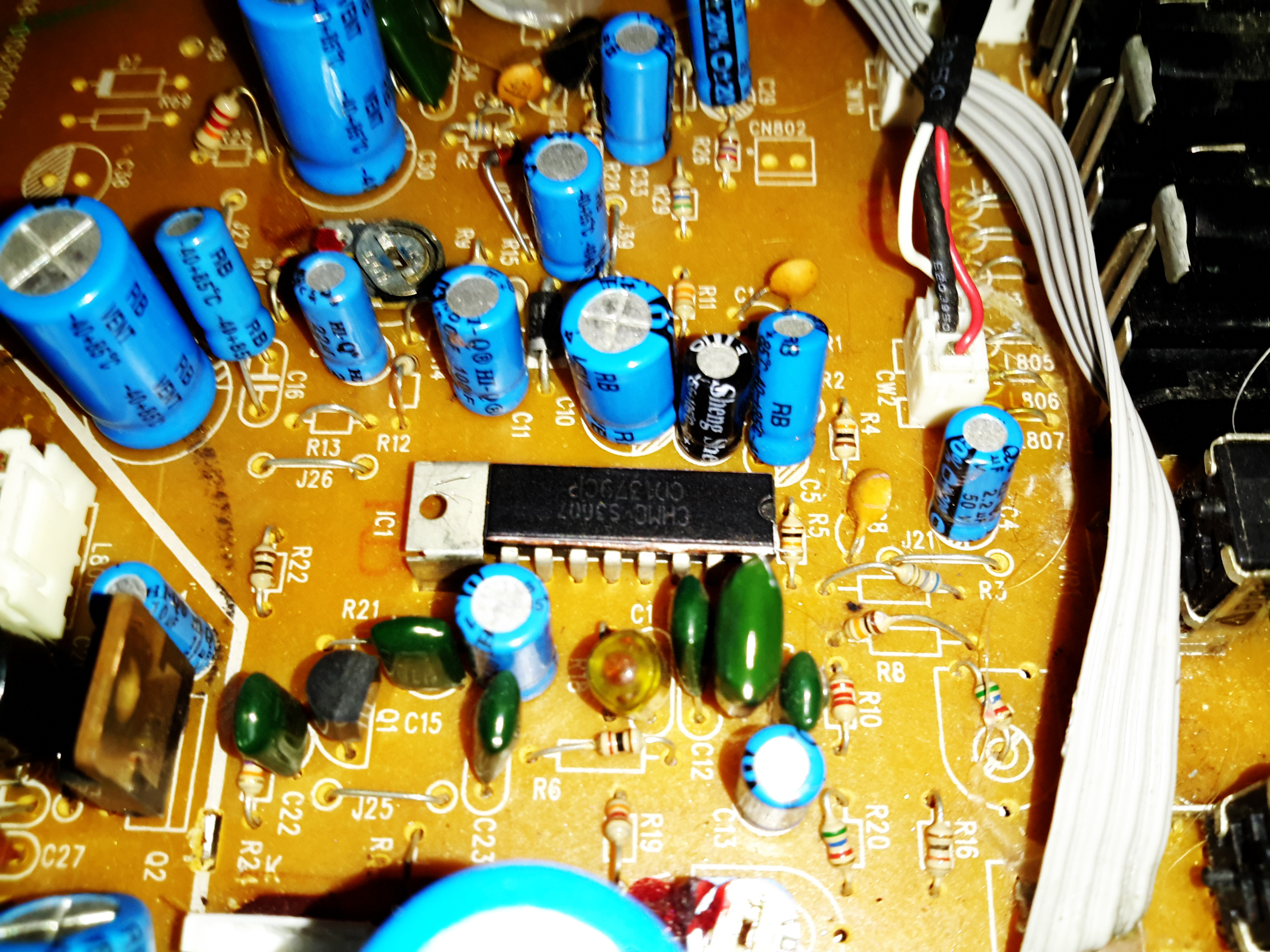
CRT Drive IC
All the drive signals for the CRT are taken care of by this single DIP IC – a CD1379CP from Silicore. Considering the older CRT-based devices I have, with entire boards twice the size of this one dedicated to discrete components required to drive a CRT, this is definitely an advance in technology. Very few external components are being used, and no custom magnetics.
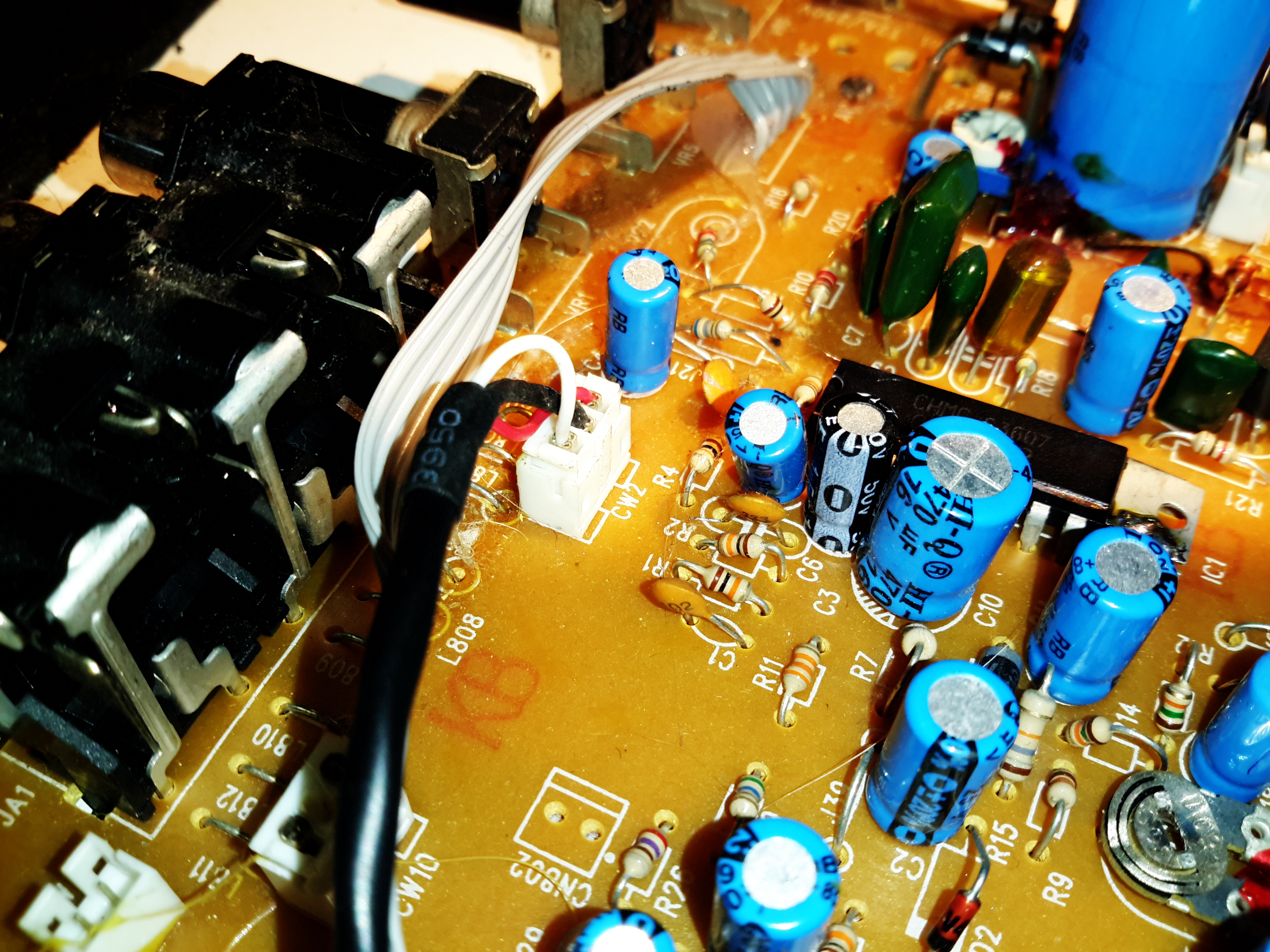
Video Input
The video signal comes in from the CD+G player module on this connector, it’s a standard composite input. The composite video is fed into an amplifier after the controller IC. This video amp is powered from a 140v rail from the flyback transformer, to give enough signal to drive the CRT cathode.
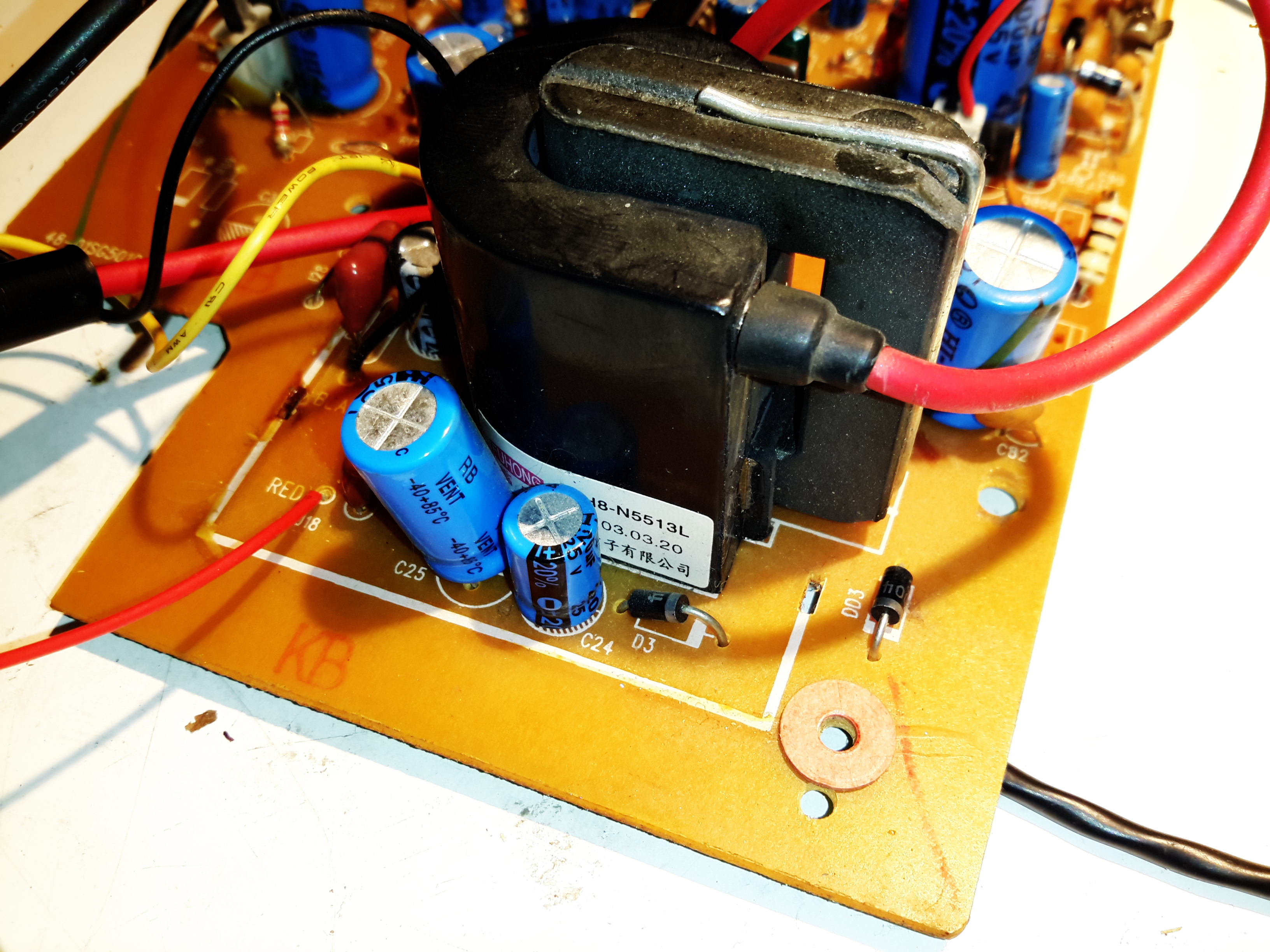
LOPT
The high voltage transformer is a BSH8-N5513L, I’ve not been able to find any data on this, but it looks like a standard off the shelf transformer from the listings on the Chinese supplier sites. There are very few support components around here, just a couple of diodes to rectify the high voltage focus supply, and no linearity coil. Weirdly, the 1st accelerating anode of the tube is grounded in this circuit. Very few adjustments are provided, most are set with fixed resistors to keep the cost low.
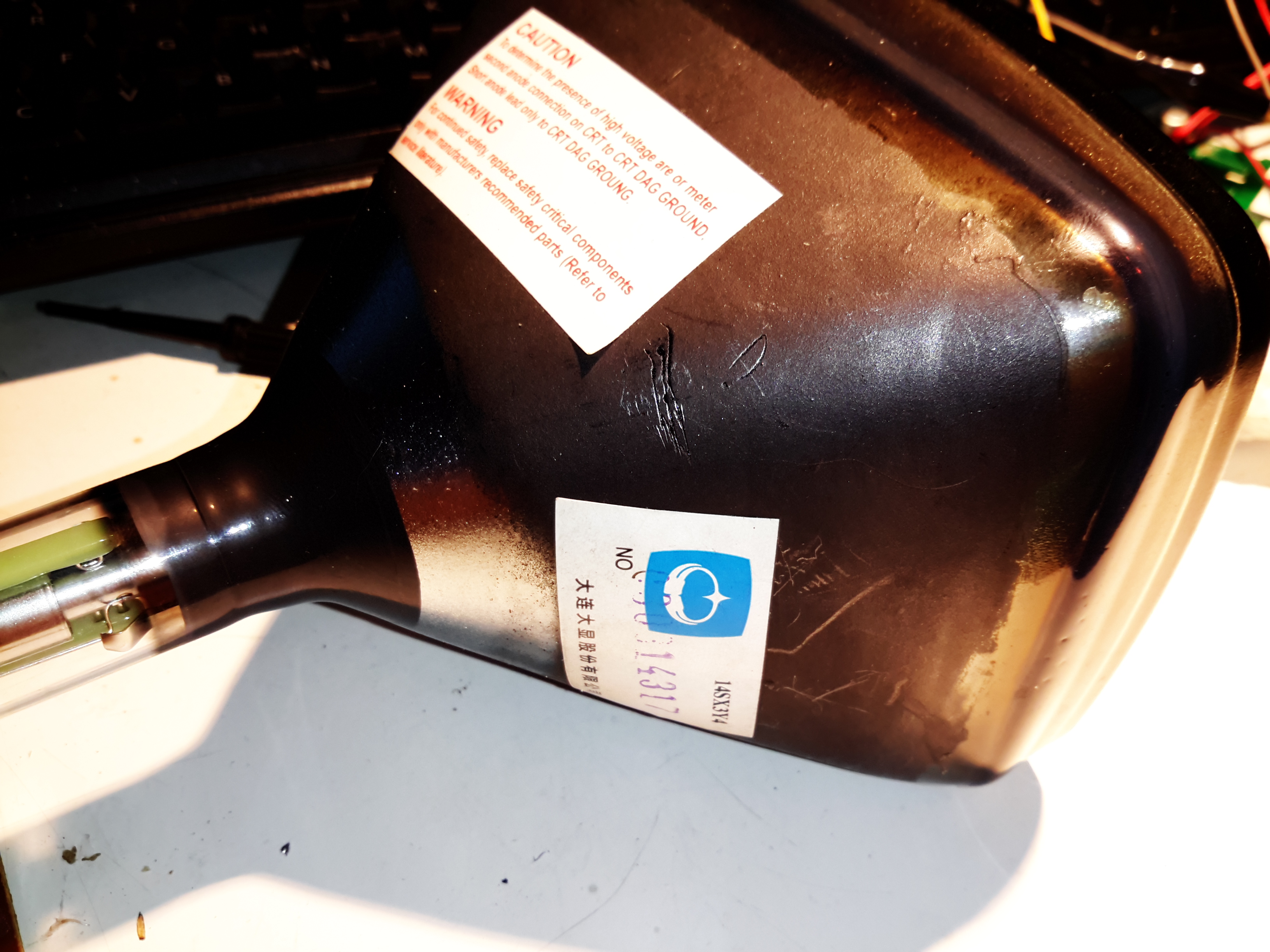
The CRT
14SX3Y4 CRT
Here’s the CRT, it’s a 5″ monochrome model. I’ve not been able to find much data on this either.
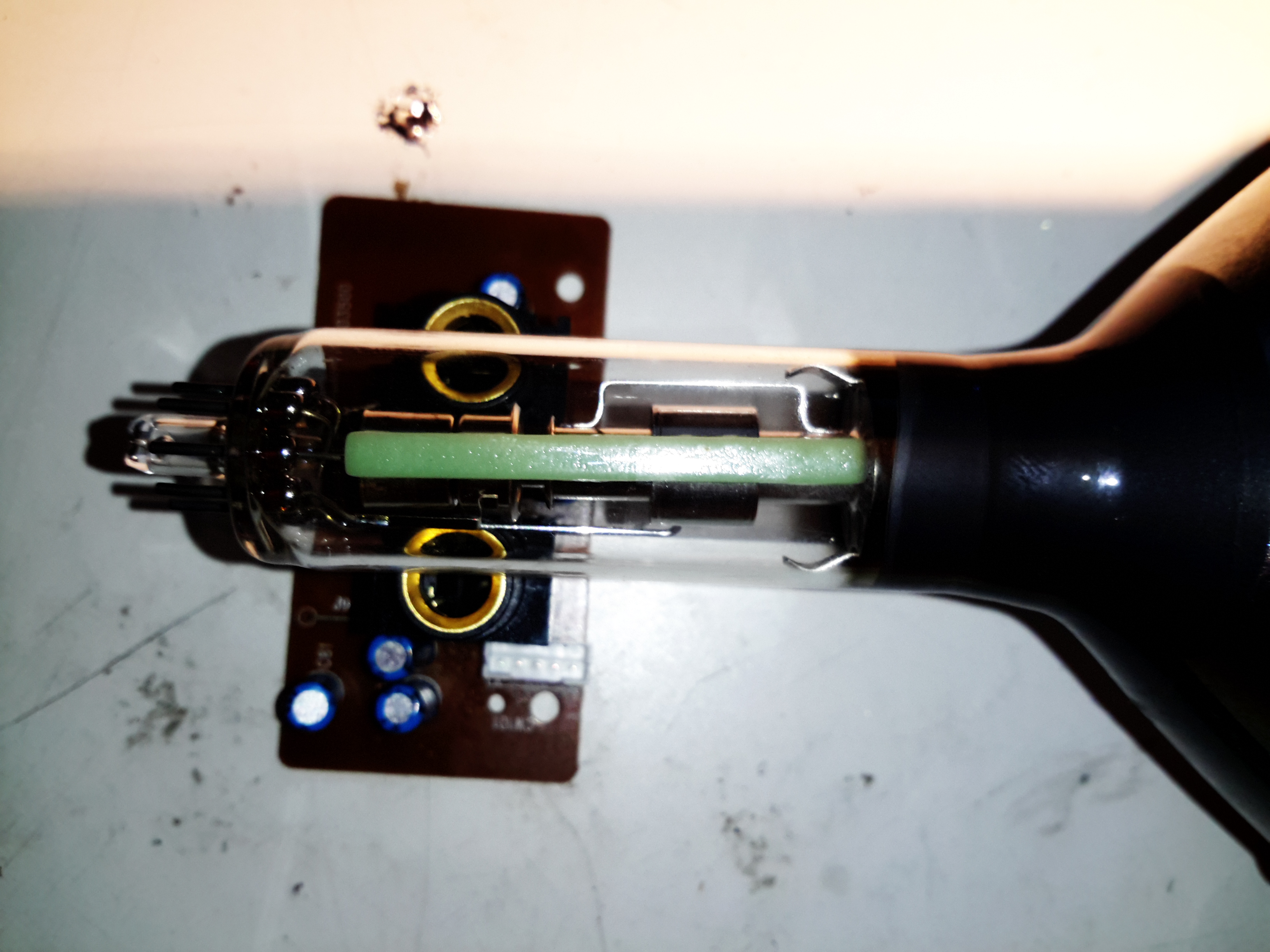
Bent Electron Gun
Seems the gents in the Shenzhen factory were having a bit of an off day when this one was made – the electron gun assembly is actually tilted in the neck of the tube – as a result the spot formed with no deflection is far from the centre of the screen. This tube does still produce a pretty good picture though, this manufacturing error is easily corrected for with the positioning magnets on the deflection yoke.
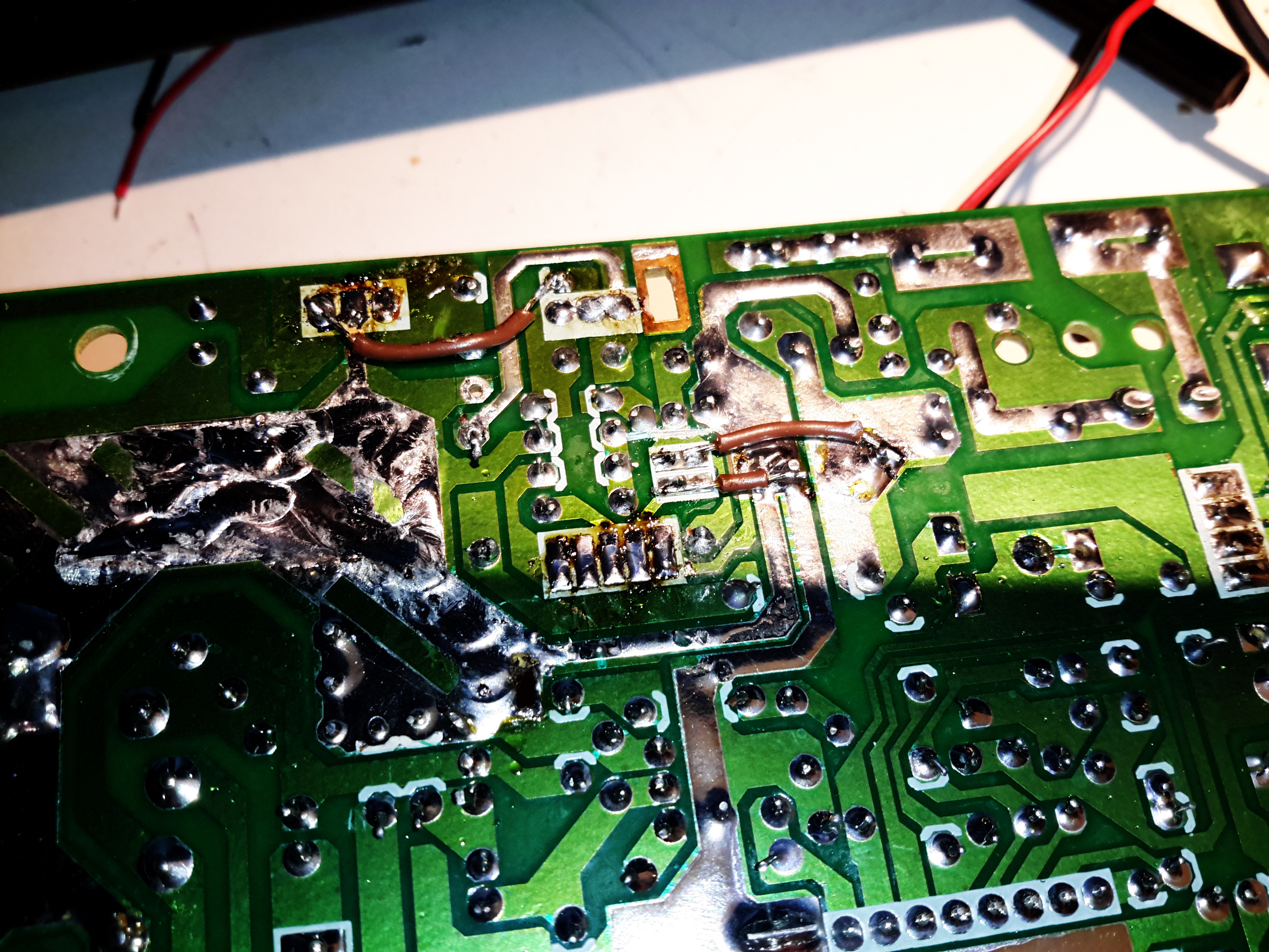
Final Mods
PCB Mods
I’ve installed a couple of mod wires on the bottom of the PCB to get this to work outside the original application, without the room heater of a linear regulator in circuit this will run fine from a 12v supply. The PCB quality is a bit naff – even quick heating with a soldering iron makes tracks fall off the laminated paper board.
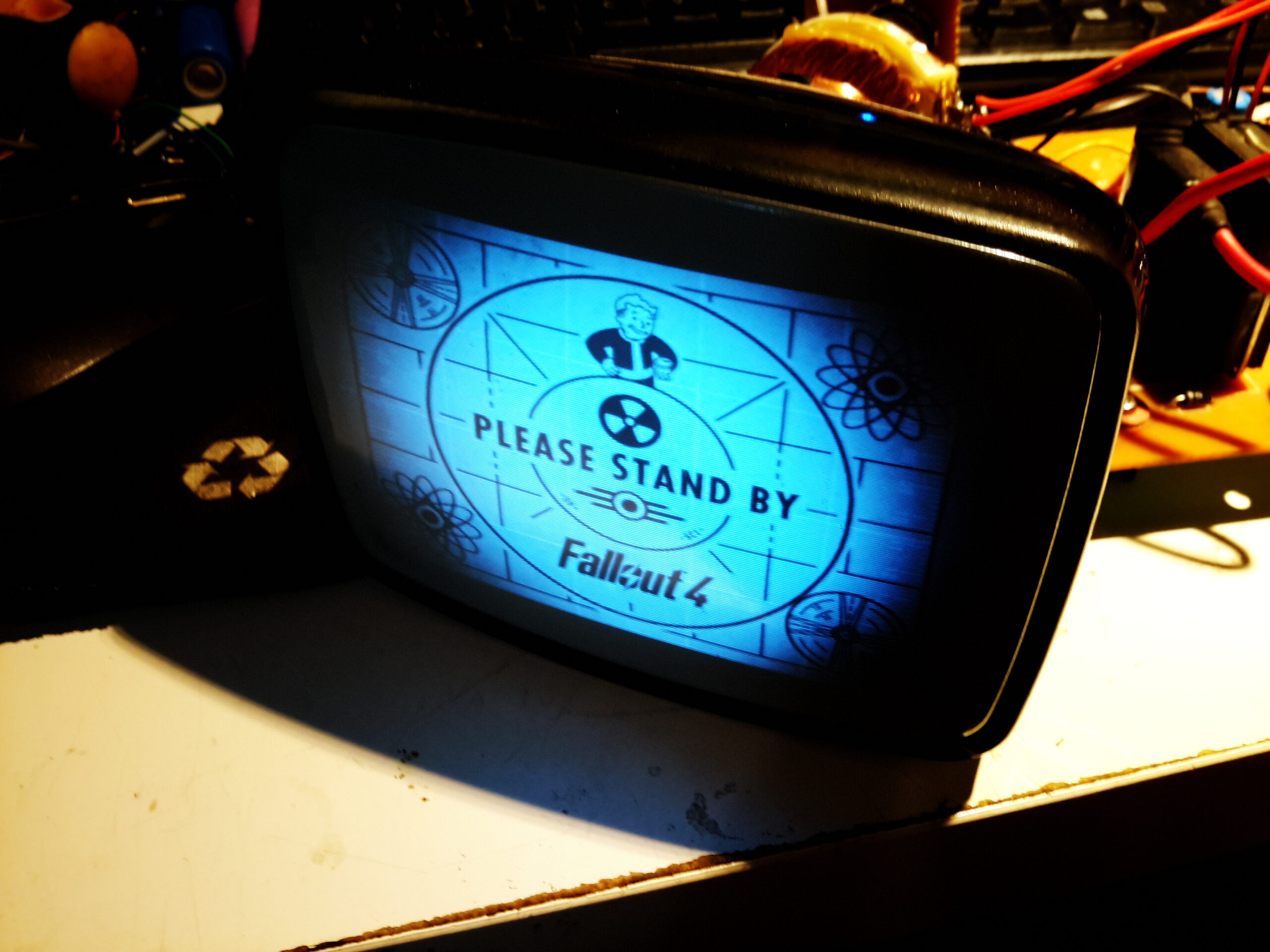
Image Display
Image quality is surprisingly good for the cheapest CRT-based monitor I’ve ever seen, I figured a Fallout reference was required here; anyone for a proper CRT-based PipBoy? 😉 Shame the phosphor isn’t green.
Tip Jar
If you’ve found my content useful, please consider leaving a donation by clicking the Tip Jar below!
All collected funds go towards new content & the costs of keeping the server online.