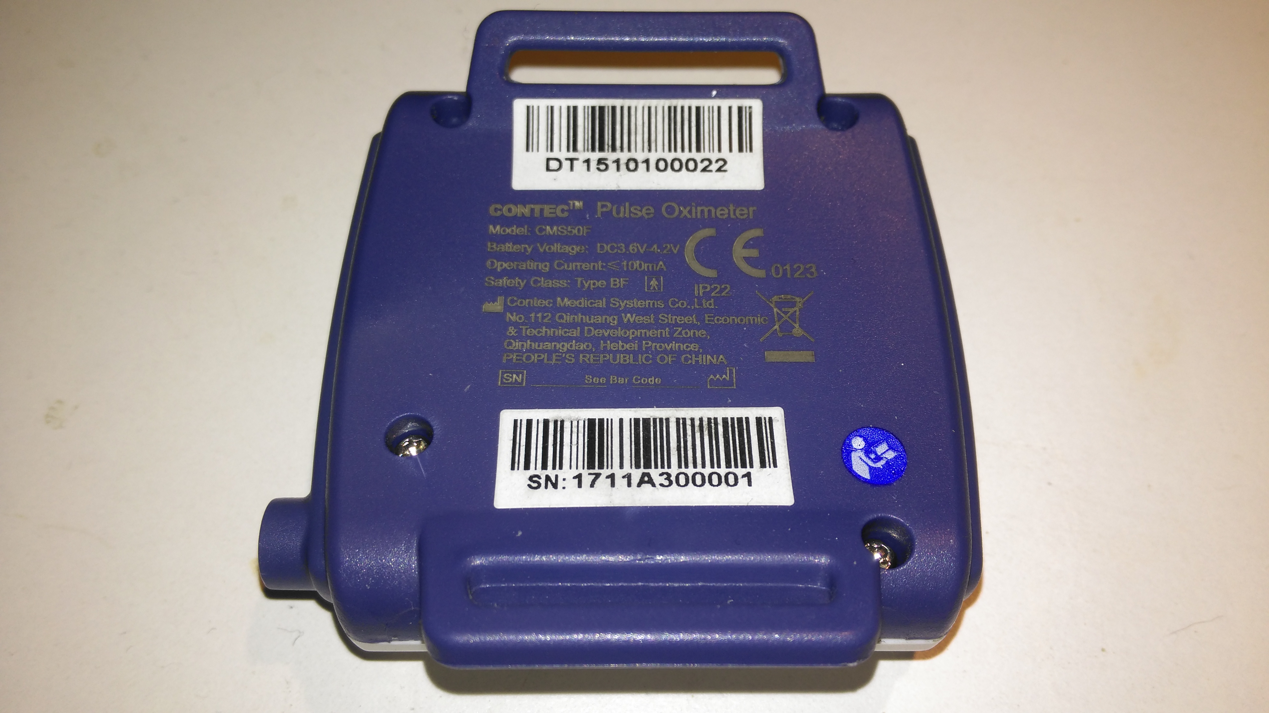
The rear has the specifications, laser-marked into the plastic. The serial numbers are just sticky labels though, and will come off easily with use.
This is the Contec CMS-50F wrist-mounted pulse oximeter unit, which has the capability to record data continuously to onboard memory, to be read out at a later time via a USB-Serial link. There is software supplied with the unit for this purpose, although it suffers from the usual Chinese quality problems. The hardware of this unit is rather well made, the firmware has some niggles but is otherwise fully functional, however the PC software looks completely rushed, is of low quality & just has enough functionality to kind-of pass as usable.
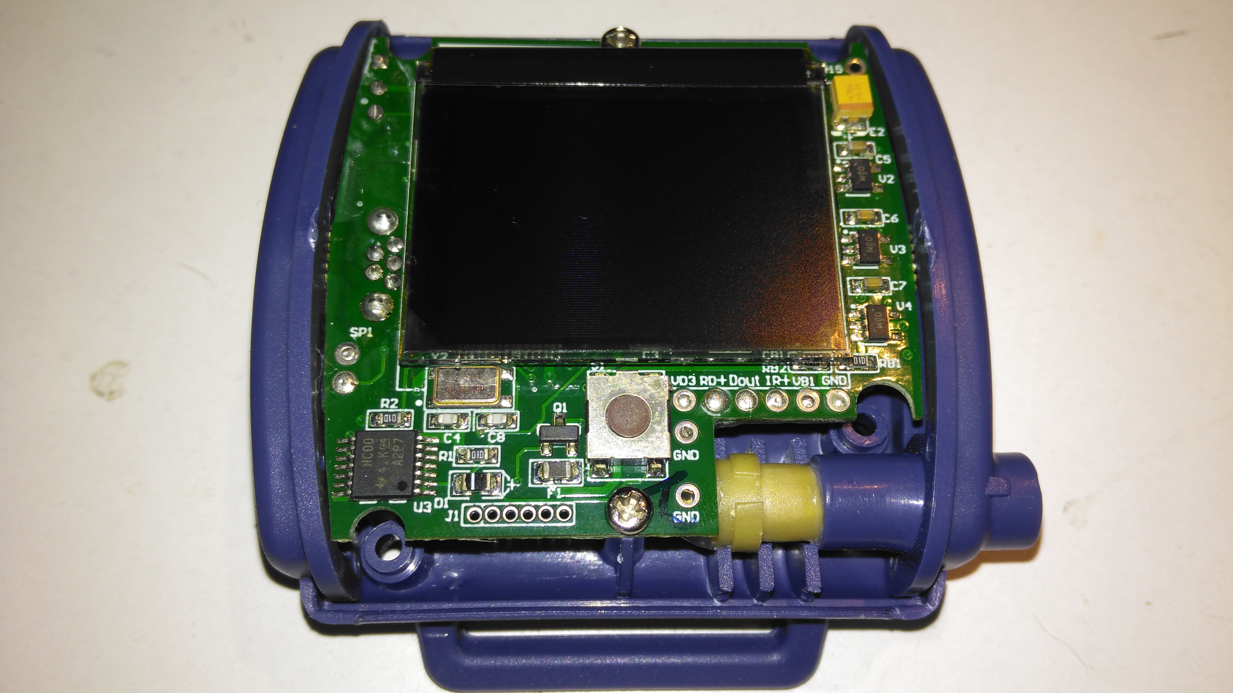
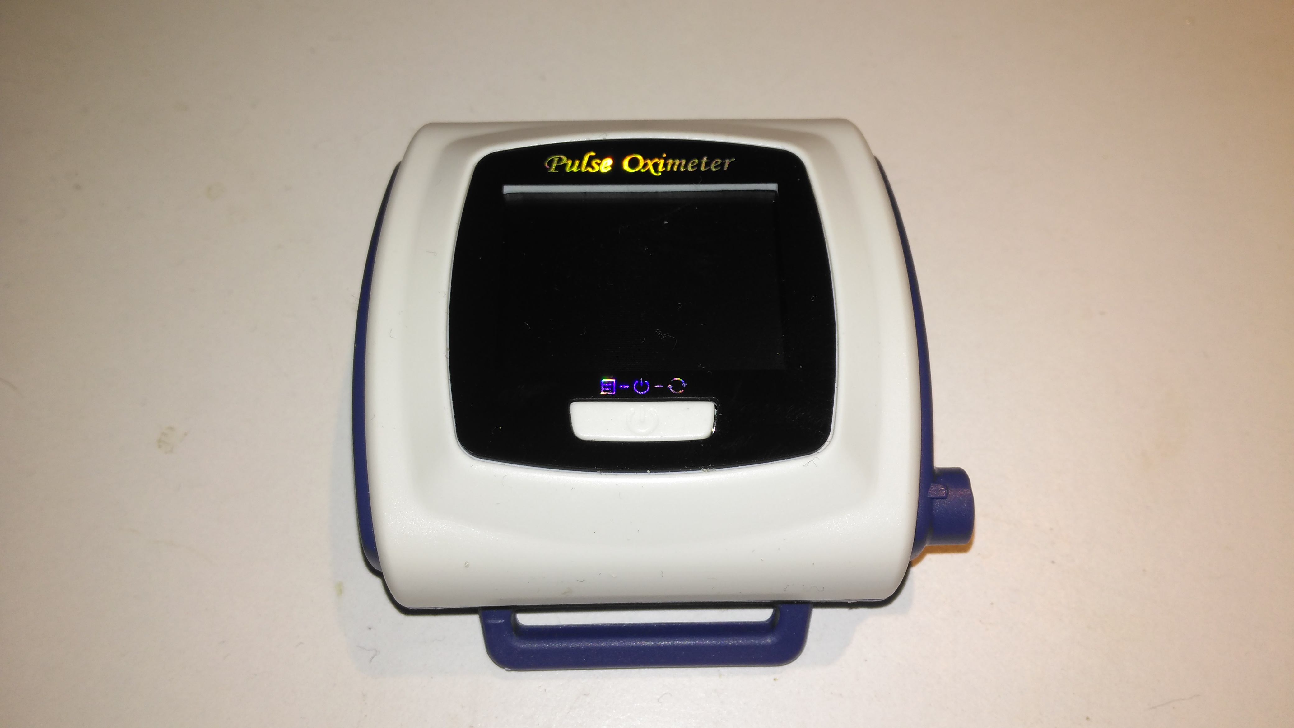
A total of 4 screws hold the casing together, once these are removed the top comes off. The large colour OLED display covers nearly all of the board here. The single button below is the user interface. The connection to the probe is made via the Lemo-style connector on the lower right.
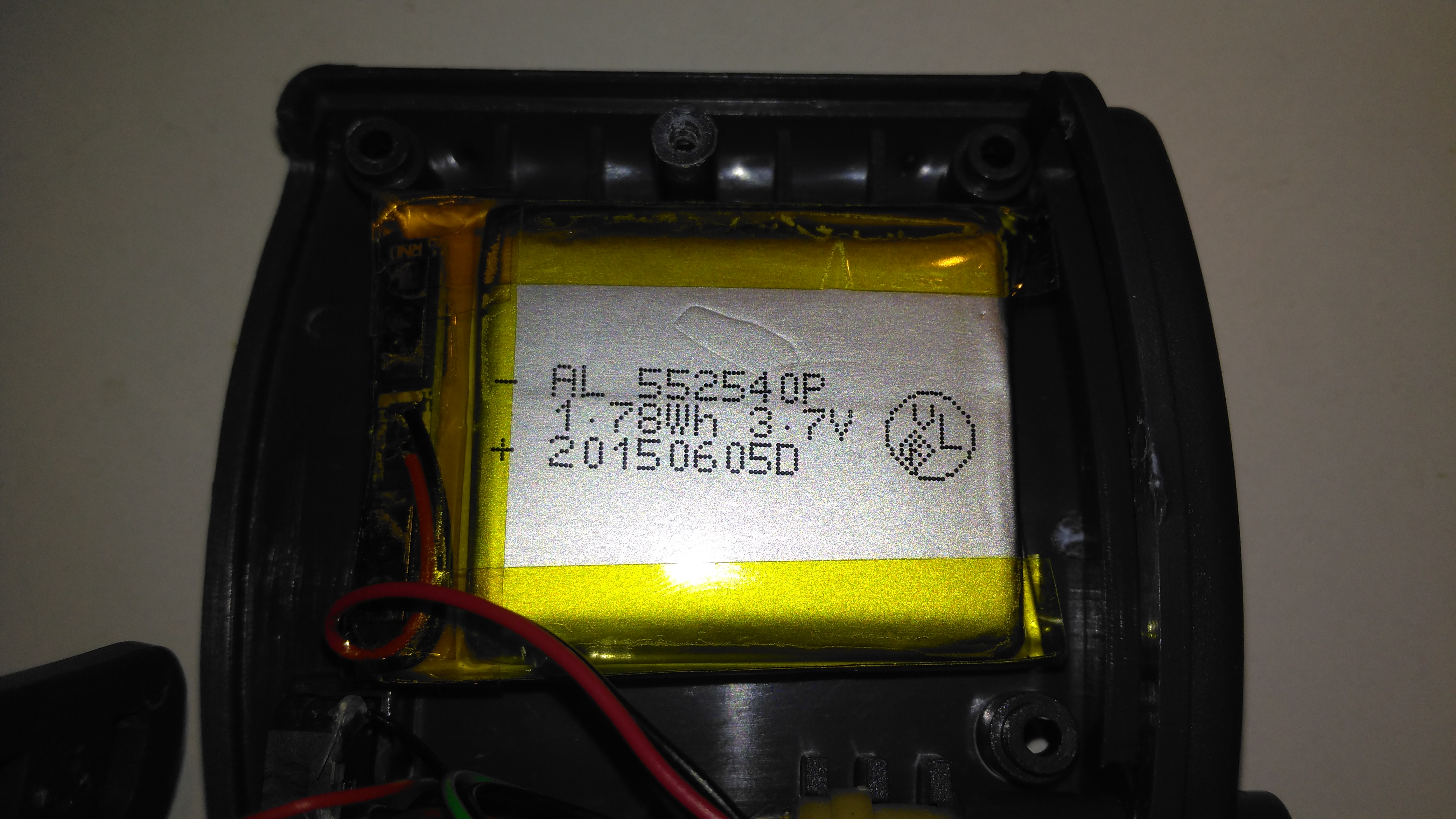
Power is provided by a relatively large lithium-ion cell, rated at 1.78Wh.
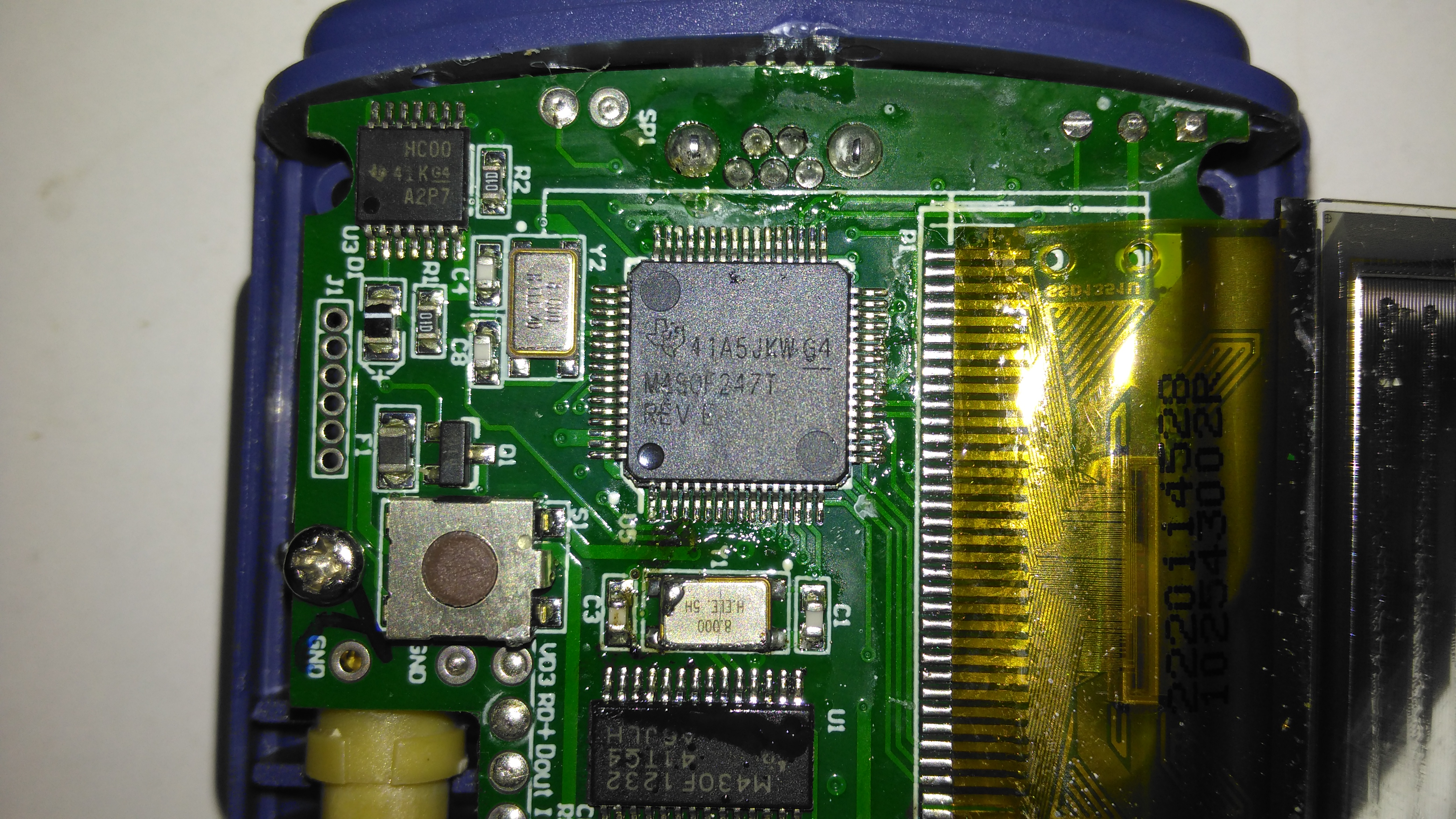
All the heavy lifting work of the LCD, serial comms, etc are handled by this large Texas Instruments microcontroller, a MSP430F247. The clock crystal is just to the left, with the programming pins. I’m not sure of the purpose of the small IC in the top left corner, I couldn’t find any reference to the markings.
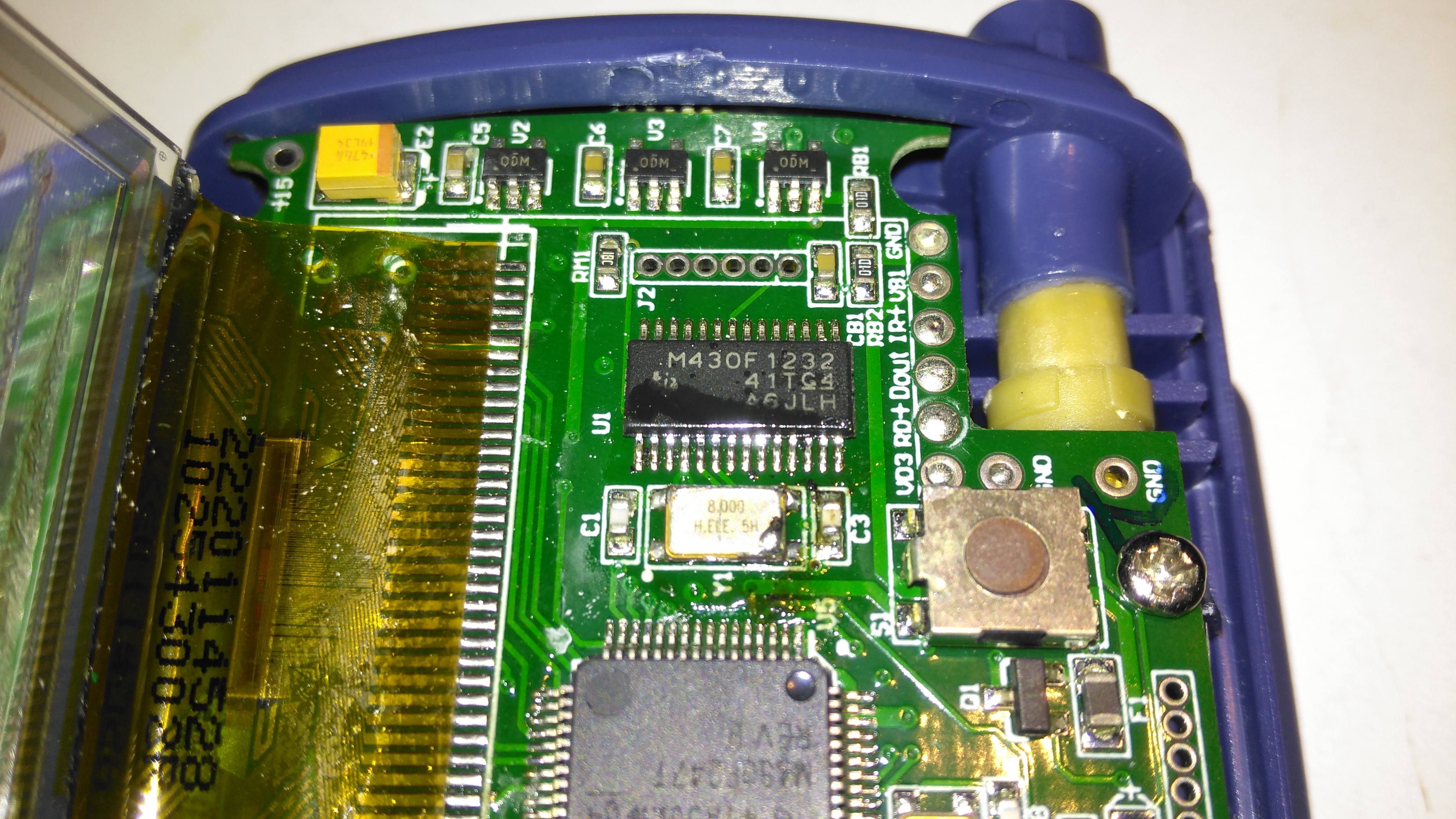
The actual pulse oximetry sensor readings seem to be dealth with by a secondary microcontroller, a Texas Instruments M430F1232 Mixed-Signal micro. This has it’s own clock crystal just underneath. The connections to the probe socket are to the right of this µC, while the programming bus is broken out to vias just above. The final devices on this side of the board are 3 linear regulators, supplying the rails to run all the logic in this device.
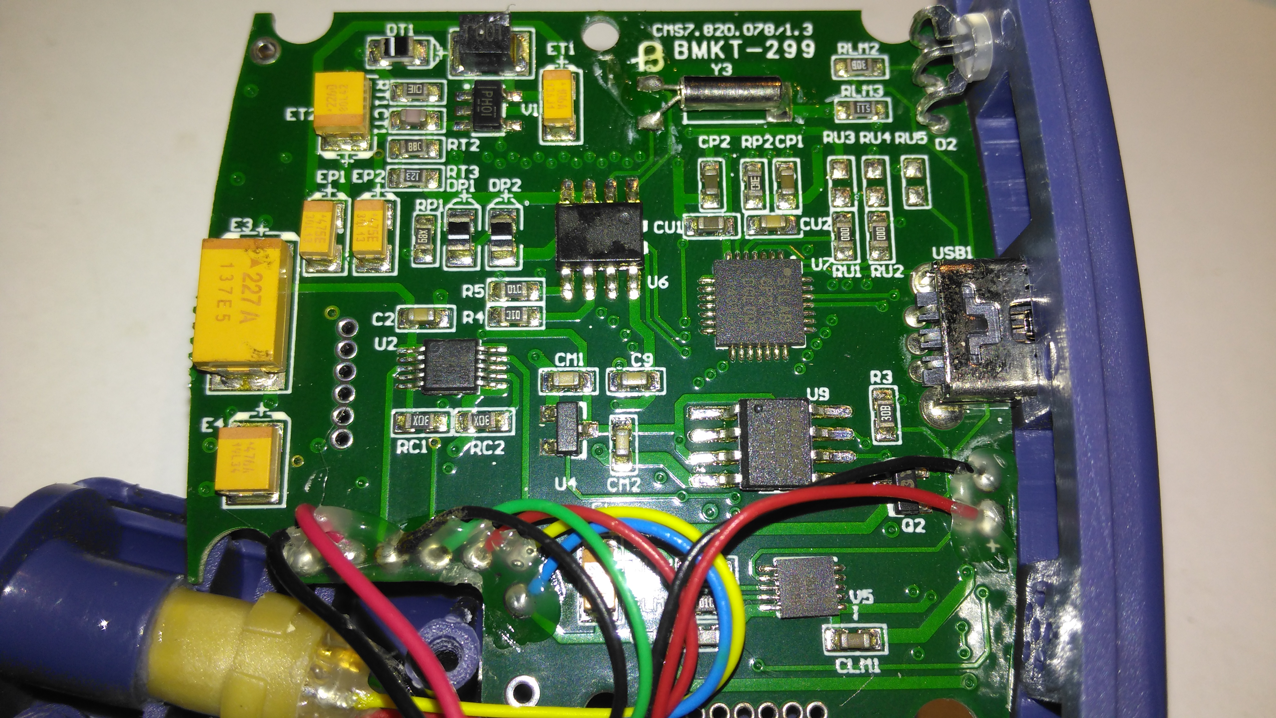
The rear of the PCB has the SiLabs CL2102 USB-Serial interface IC, the large Winbond 25X40CLNIG 512KByte SPI flash for recording oximetry data, and some of the power support components. The RTC crystal is also located here at the top of the board. Up in the top left corner is a Texas Instruments TPS61041 Boost converter, with it’s associated components. This is probably supplying the main voltage for the OLED display module.

How can I test / fix what causes the backlight on the cms-50f to become very dim and make the screen hard to read.
Hi Rick,
There is no backlight on the CMS-50F Oximeter as the display is OLED. There is an option in the settings to change the brightness, but if that is set high on your unit I would suspect there is a fault.
Thanks for reading!
de 2E0GXE
Is there anyway to increase the maximum volume of the alarms ? Currently have it set to max but it’s not quite loud enough for my aging parents ears. Thanks for the tear down BTW. Nice work!
Hi,
I haven’t found any option to change the alarm volume unfortunately.
Hi,
thank you your nice work! I am wondering if it would be possible to connect the Contec CMS-50F with an external controller (a computer) to be able to send a signal to start of the recording. I am trying to synchronize the oximeter with a video camera recording. Also, do you happen to know if this would be specific to the “F” model or also the Contec CMS-50D could have this capability?
Thank you for your help
Hi Camilla,
I’m not sure of the capabilities of the D version, but you could always give it a go.
For logging I’ve used something by the name of SleepyHead, which is an open source project. The code should be available, as well as details of the serial protocol.
https://sleepyhead.jedimark.net/
Unfortunately it’s not being maintained any more, but there should be enough there to get you going.
I’ve lost the proprietary USB-Data cable that came with the CMS50F, and am attempting to build my own.
My board looks slightly different than yours (mine says “CMS7.820.078/2.1” and “BMKT-1295”), and I’m having trouble narrowing down which pins do what, but was hoping I could get some insight from you regardless. Photos of my board are at https://share.icloud.com/photos/0UfX_xKElawsaY9acWmO0bqww
I’m thinking about soldering wires directly to the TX and RX pins, and connecting them to a FT232R USB UART that I have lying around (for arduino projects), which will then connect to the computer. While I can’t see TX and RX pins on your board, mine does have pins labled “1232RX” and “1232TX”. What do you think? Worth trying? Or would I more likely need to find the pins on the USB port which are connected to RX and TX?
Hi Kyle,
Your board is definitely different from mine – is this the unit that connects the finger sensor via the USB port? There are 10 pins in that version of the connector (I have another SpO² unit that does use that connector too) and while the sockets are readily available, I’m struggling to find the matching plugs. Search for MiniUSB 10-Pin.
The pads on the board do look plausible as the RS-232 interface, and I wouldn’t have thought a device like this would be using the other serial control lines for anything. I’d definitely have a go at hooking a USB UART to the unit, but I’d start at 3v3 voltage levels, just in case the unit isn’t 5v tolerant. I certainly don’t see a pad for a 5v rail, but there are a couple that look to be 3.3v.
A scope really helps here, but you may have some success without one. If you manage to get a valid serial link off the pads, try & find the correct ones on the connector – you may be able to make up a new cable.
Do let me know if you get stuck.
Cheers