I recently managed to score a 3″ B&W portable TV on eBay, a Panasonic TR-3000G. As these old units are now useless, thanks to the switch off of analogue TV signalling, I figured I could find a composite signal internally & drive the CRT with an external source.
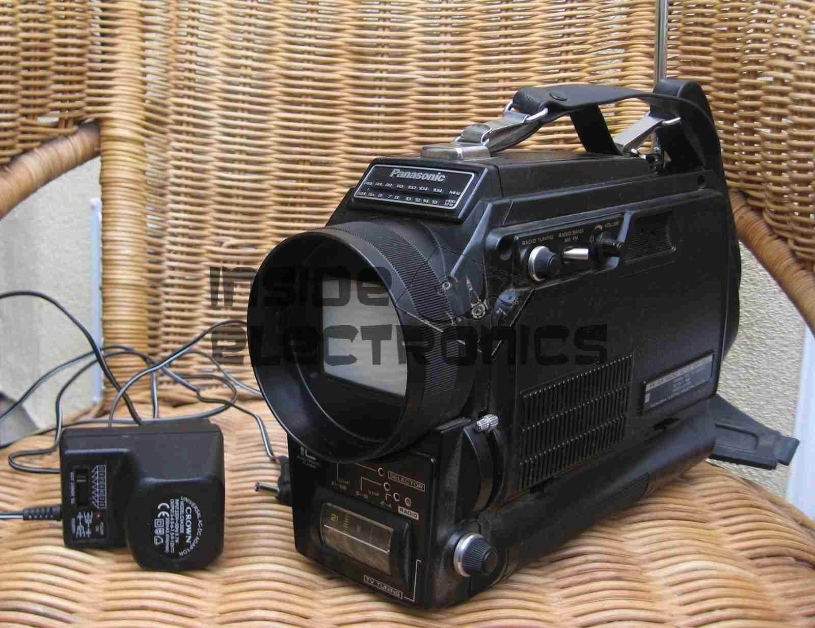
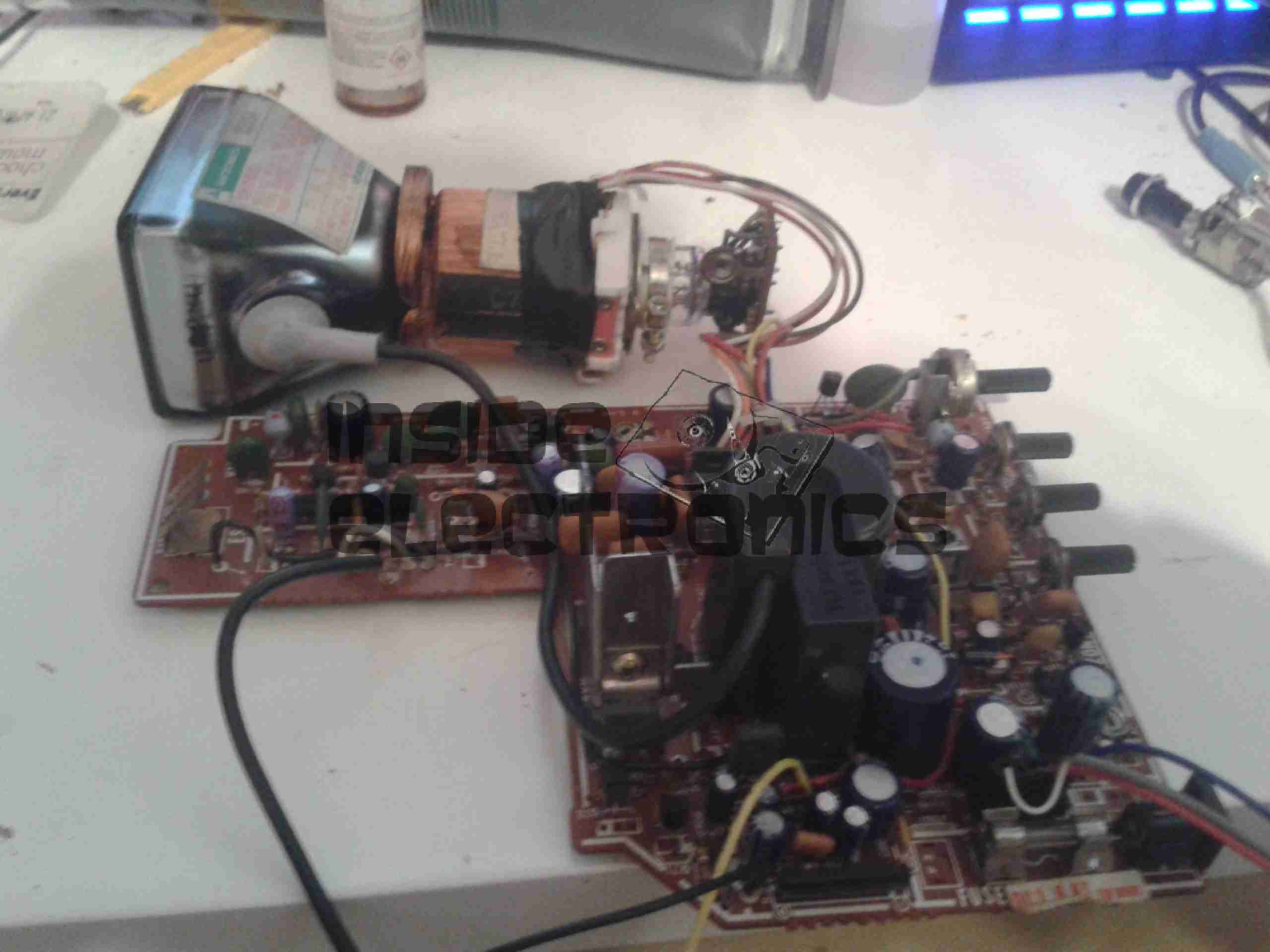
Here’s the TV in it’s native state. Running from 9v DC, or 6 D size cells. I’m guessing from somewhere around the 1970’s. Here is the CRT & associated drive circuitry, removed from the casing:
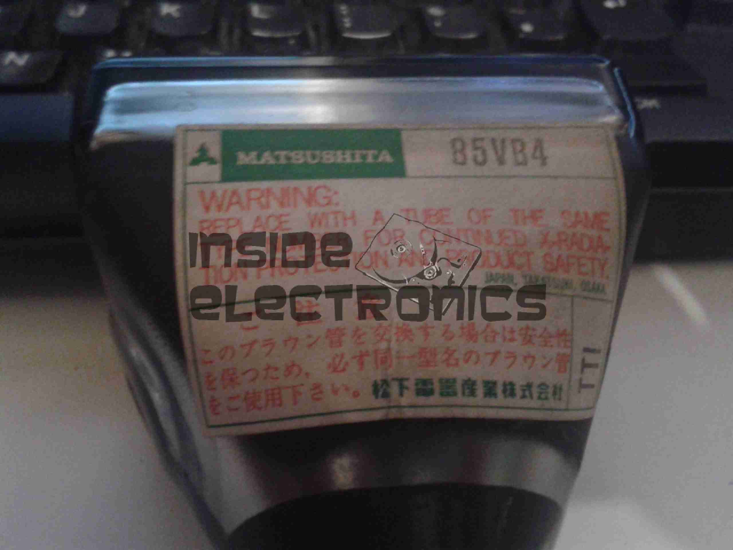
After dissecting the loom wiring between the CRT board & the RF/tuner board, I figured out I had to short out Pins 1,2 & 5 on the H header to get the CRT to operate straight from the power switch. This board also generates the required voltages & signals to drive the RF tuner section. I have removed the loom from this, as the PCB operates fine without. It doesn’t seem to be fussy about power input either: it’s specified at 9v, but seems to operate fine between 7.5v & 14.5v DC without issue.
Tracing the wiring from the tuner PCB revealed a length of coax snaking off to the section marked Video/Sync. I successfully found the composite input!
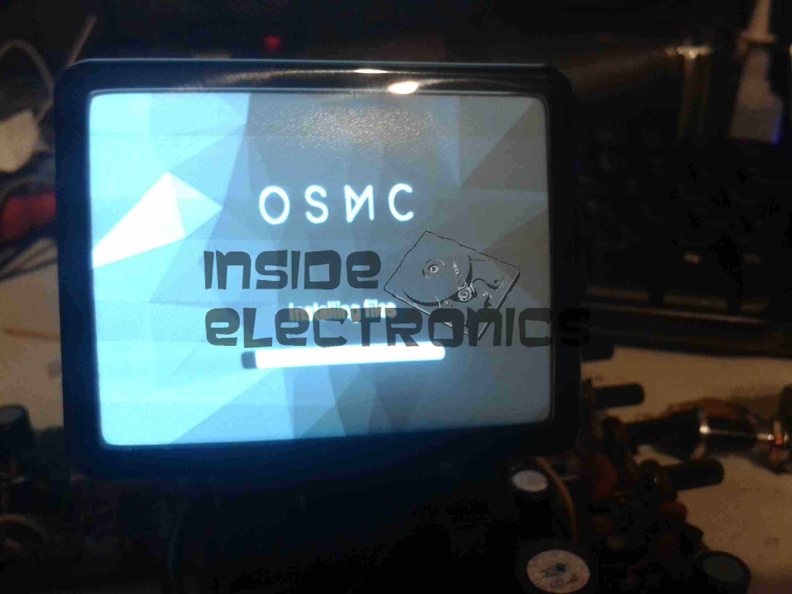
A quick bit of wiring to a Raspberry Pi, & we have stable video! For such an old unit, the picture quality is brilliant, very sharp focus.
Closeup of the CRT itself. I haven’t been able to find much data on this unit, but I’m guessing it’s similar to many commercial viewfinder CRTs.
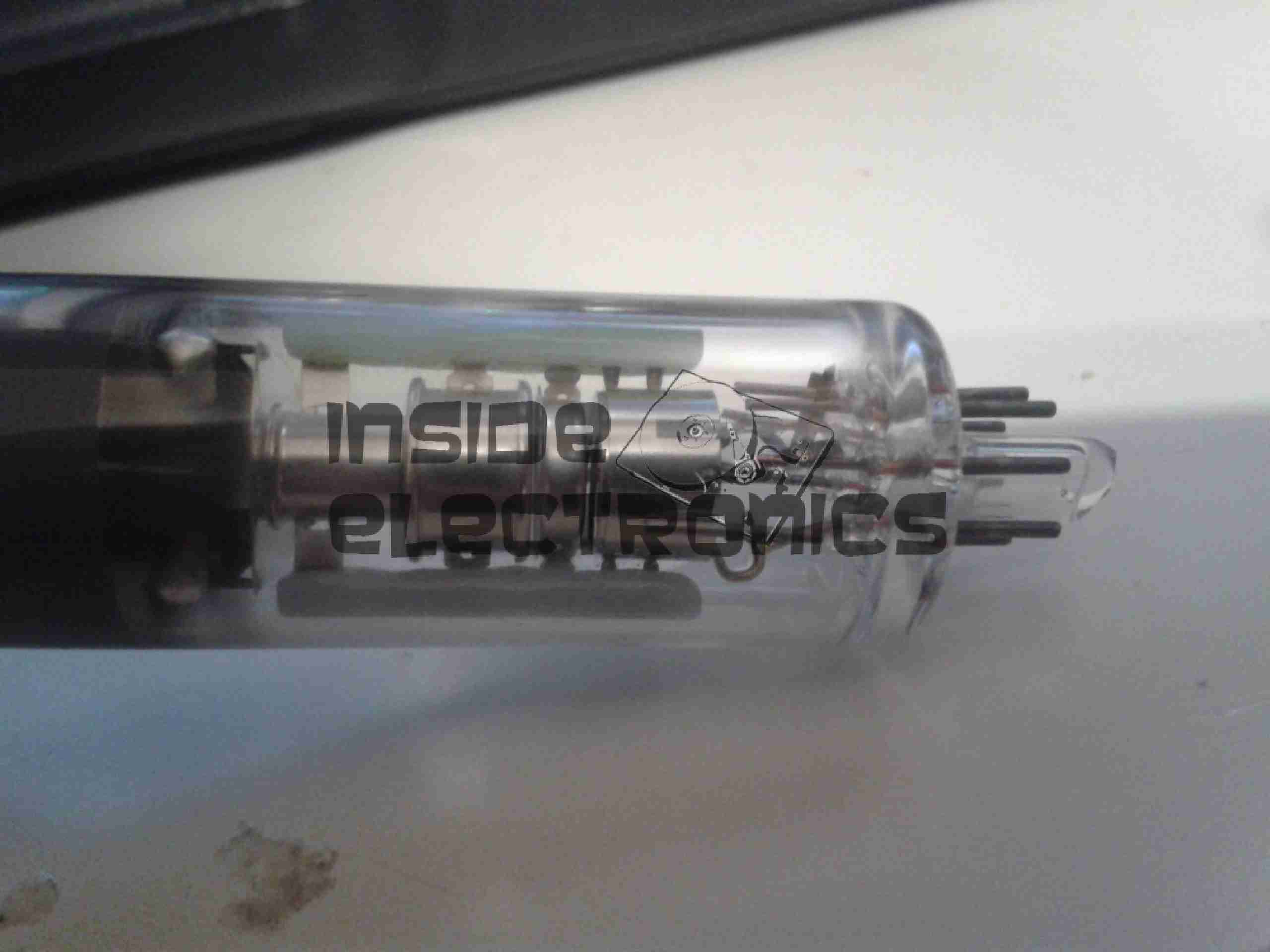
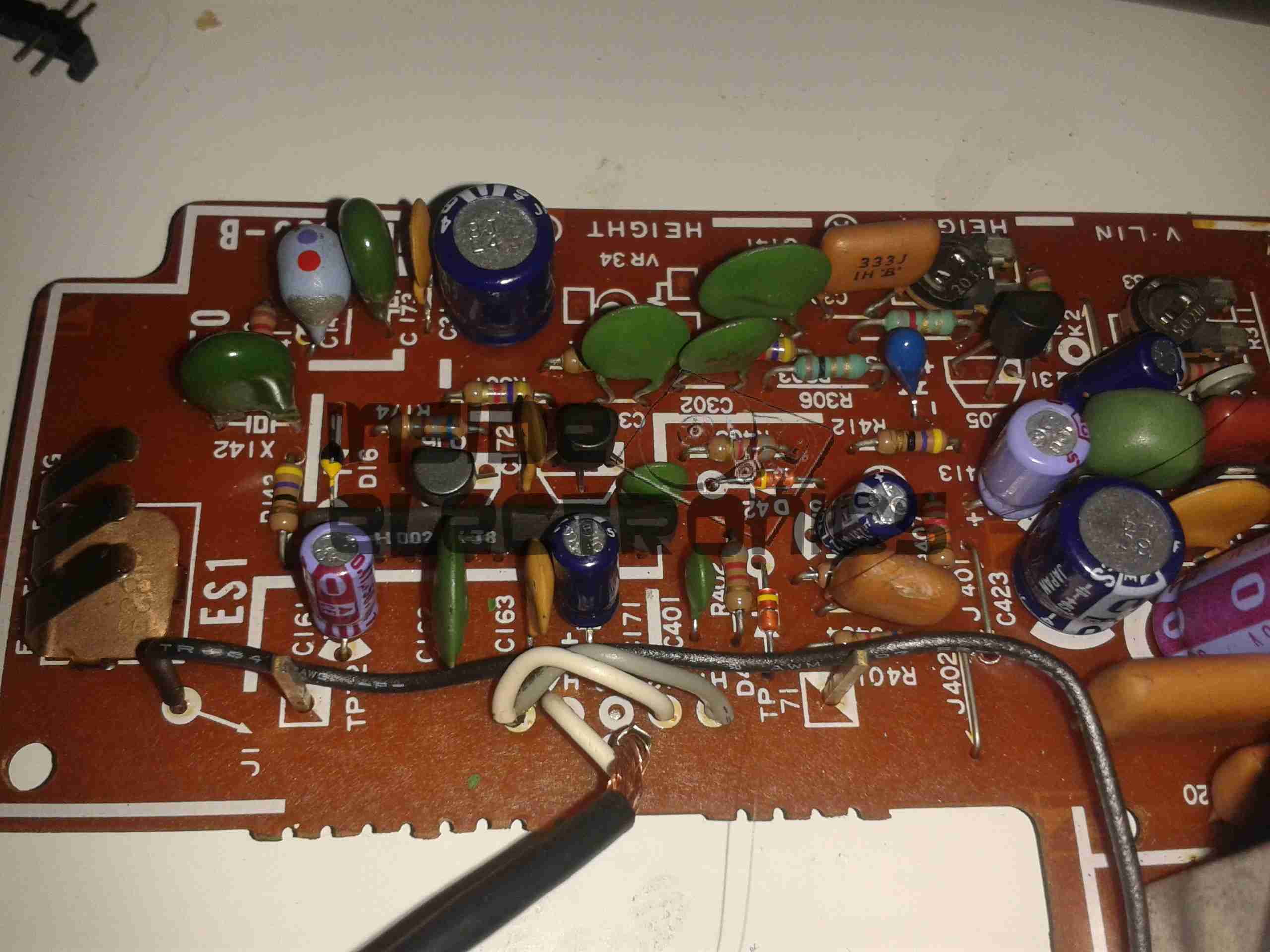
Amazingly, there isn’t a single IC in the video circuitry, it’s all discrete components. This probably accounts for the large overall size of the control PCB. Viewfinder CRTs from a few years later on are usually driven with a single IC & a few passives that provide all the same functions.

I have one of these crt’s if you want it..
Certainly, I’m always after more CRTs for the collection. If you could drop me a message via the contact form we can sort something out 🙂
http://www.experimental-engineering.co.uk/contact-the-author/
de 2E0GXE
Hi. I’m looking to do something similar with a 5.5 inch black and white set and a ROKU box, to convert it into a self-contained portable IPTV. I very much like classic CRTs, they seem to have a much more dynamic picture than LCD. I bought an LCD last year and I’m dissapointed with the contrast even in HDMI mode. My 36 year old Philips BM7502 still has a pin-sharp picture from a digibox or ROKU, although the LOPT now occasionally shreiks!
Any hints on feeding a ROKU signal (standard 625-line composite video + audio) into a CD5151CP based telly, bypassing the tuner and IF. I so far have found wire ins and outs for the main chip; video out is Pin 5 of the 28 pin DIL package; I assume that is actually fed to the cathode amplifier and we need to find a way to synch the chip to an external video signal.
With the giveaway prices of these sets and the cheapness of the digital converters there could be a demand for this sort of thing!
Hi Mongoose,
I’ve not worked on a TV of this type, looking up the datasheet for the IC mentioned tells me it has the all the video functions built in, including the Video IF. This IC is the equivalent of the KA2915 LSI Audio, Video & Deflection IC. Injecting a composite signal into Pin 5 would get a picture, but you’d need to build a small circuit to feed the sync separator input on pin 6. The datasheet for the KA2915 has an example application circuit, that should give you all the information you need.
Let me know if you need any more help!
de 2E0GXE
Thanks for the information. I shall have a look at the data sheet and see if I can add the required circuitry. I seem to be coming across synchronisation problems with the other sets I’m working on. I have a zenith monitor chassis from an old defunct apricot computer that i’m also adapting to receive video from a composite digital device. Horizontal is running at correct rate 15625 Hz but vertical running slow at about 30 Hz, resulting in readable text and logos but flashing at multiple points on the screen. I’m struggling to find any information or Sam’s for it; even the great Shango066 doesn’t have any information! He has suggested some of the components in the vertical circuit may be out of tolerance.
The third set is based on a pcw8512 monitor which has had the computer board removed, but retains the monitor PCB. Looking at the circuit diagram it appears that amstrad used a lot of television ICs in the monitor, and frequency of the timebases is correct for UK TV. I just need to figure out how to feed the TV ICs the correct signal from my composite video signal. I have to bypass a digital 7400 that served as the original input. I plan to split the composite signal into 3 paths; one to feed the cathode driver, one to feed the vertical sync separator and the remaining to feed the horizontal synch separator. I’ll also include some kind of contrast control in the cathode circuit so that we can get the greyscale correct.
Any advice would be appreciated.
Regards Matt
Mongoose digital conversions
Hi Matt,
I’d check the timing components in the vertical oscillator. The old units I have have had a couple of issues with timebase frequencies due to aging of the components. In my case replacing electrolytics & carbon trimmer resistors with new components helped the issue. Datasheets & schematics may be essential though! (The application information in the datasheets may be enough help in the case of no schematic for the chassis being available).
As for feeding the Amstrad chassis with a composite signal, again datasheets for the internal decoding ICs & a full schematic will definitely be of help, the place to inject the signal is usually pretty obvious from these. I’ve never gone as far as dividing the signal out to the subsections though, as everything I’ve experimented with so far, this hasn’t been required. Generic schematics for B&W composite-based TVs might be of assistance to give you some hints at the required circuitry though.
Dear Engineer, I’m dealing with Sony FD-525, I would like to add composite input to it. Sony FD-525 has few integrated circuits, KA2915, AN5707NS and 2904D. How would I go about the composite input?
I noticed that pin 5 on KA2915 is Video Output. Should I remove whole KA2915 chip and hook up the pin 5 pad to composite input and call it a day?
Please advise.