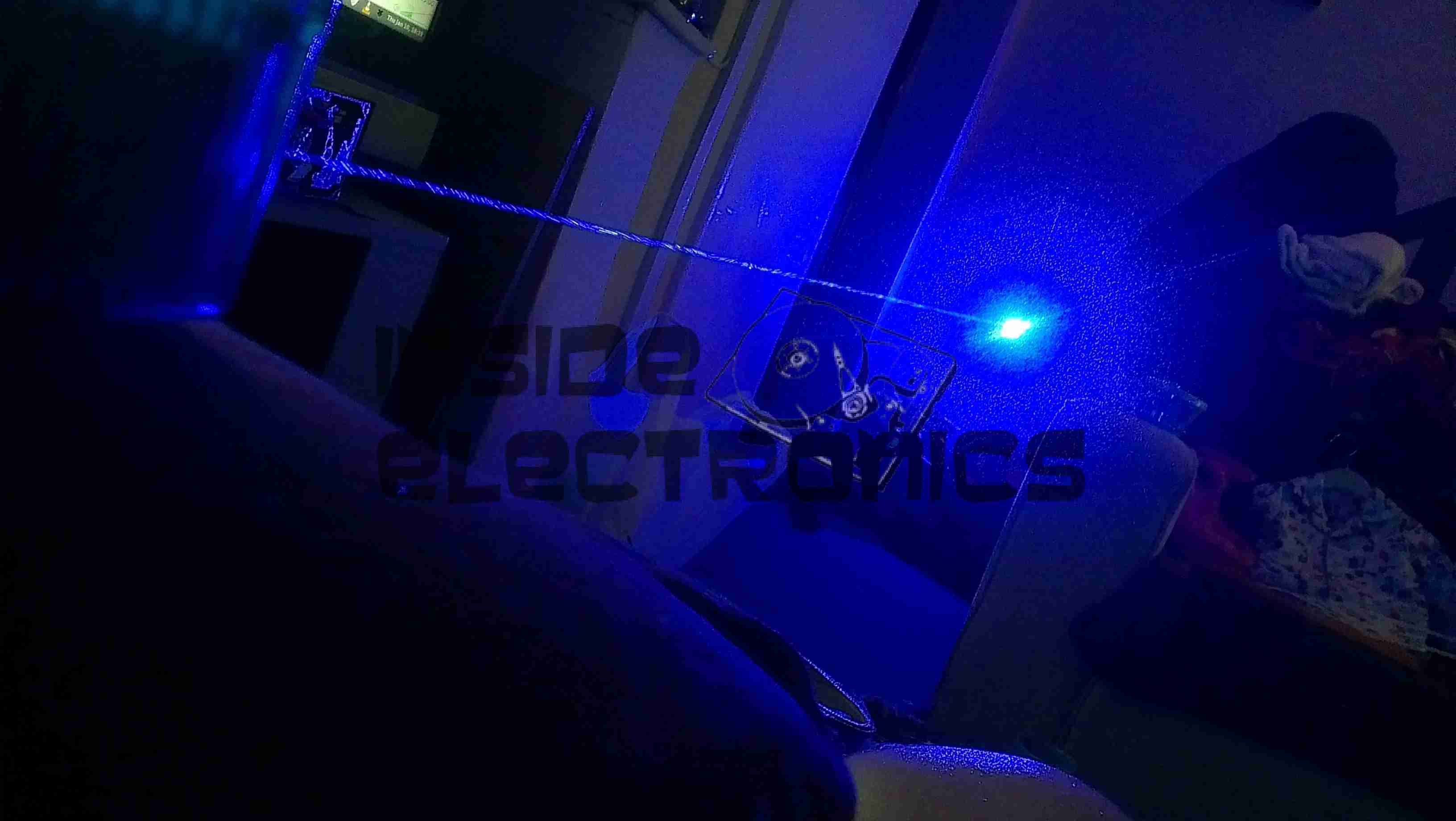

- Beamshot 1
Here’s a couple of beamshots from the new laser, running at full power.
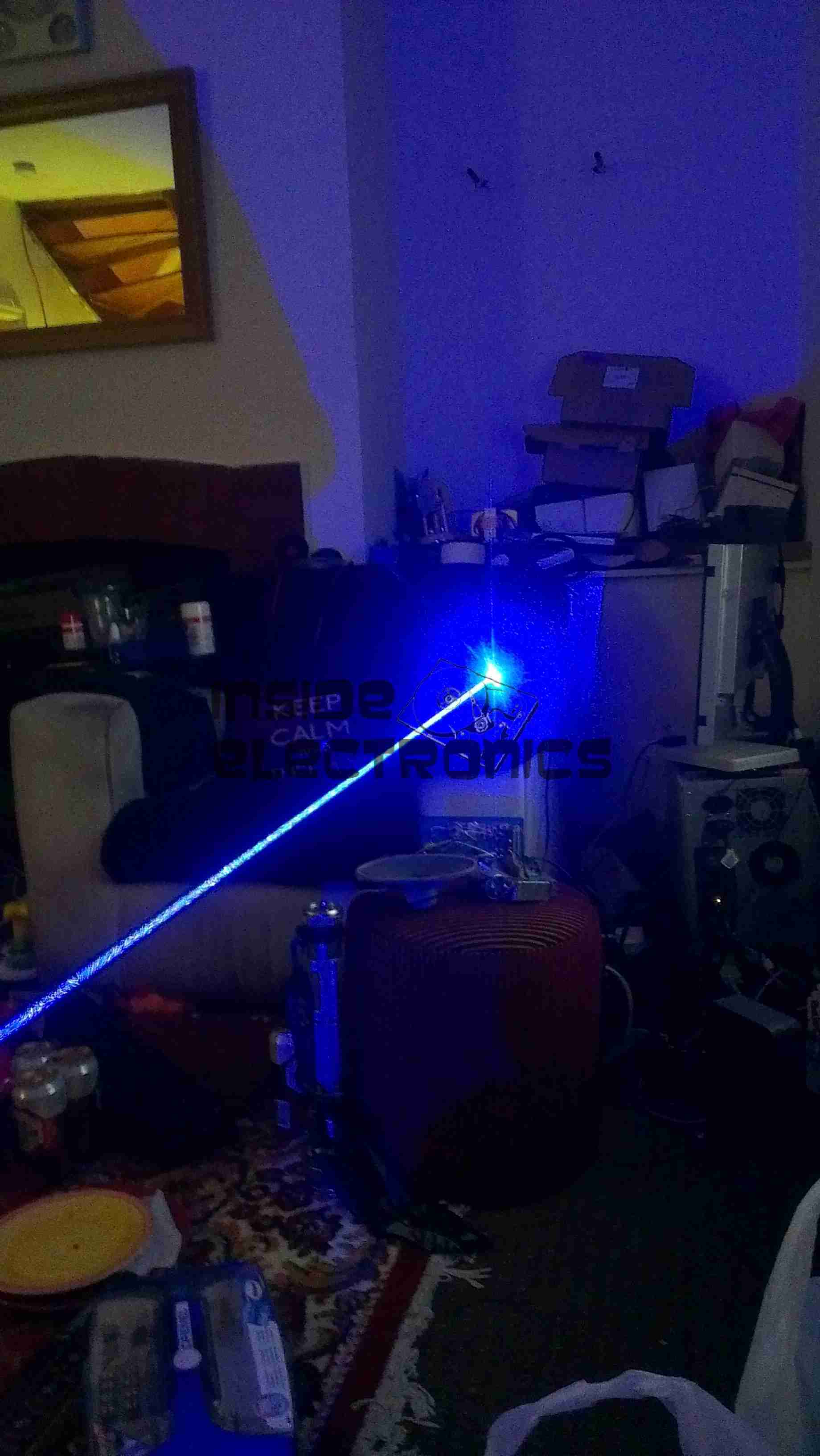
Here’s a couple of beamshots from the new laser, running at full power.
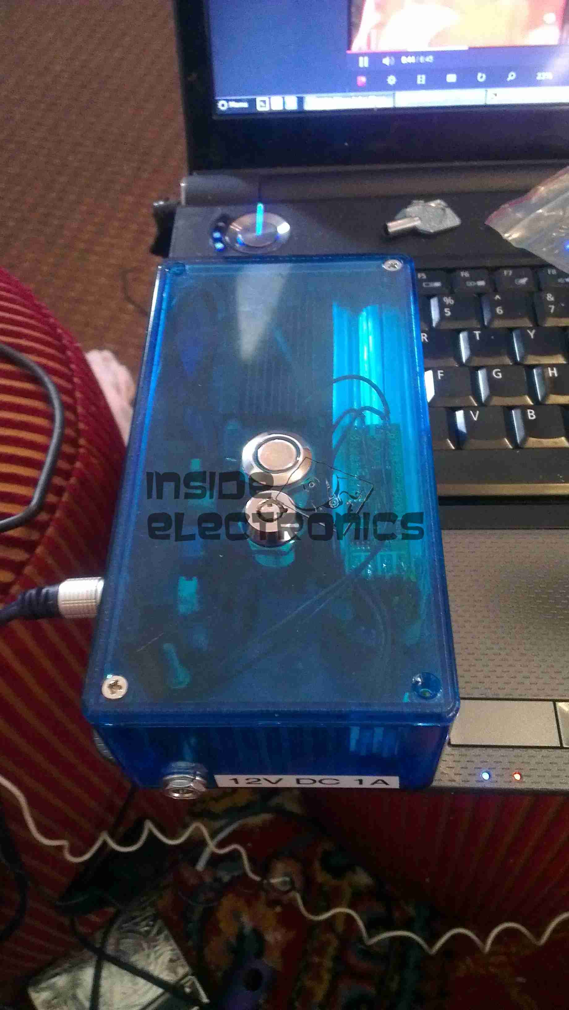
Here is a followup from the 1.5W laser module post.
The module has been fitted into a housing, with a 2.2Ah Li-Poly battery pack. Charging is accomplished with an external 12.6v DC power supply.
Above can be seen the pair of switches on the top, the keyswitch must be enabled for the laser to fire.
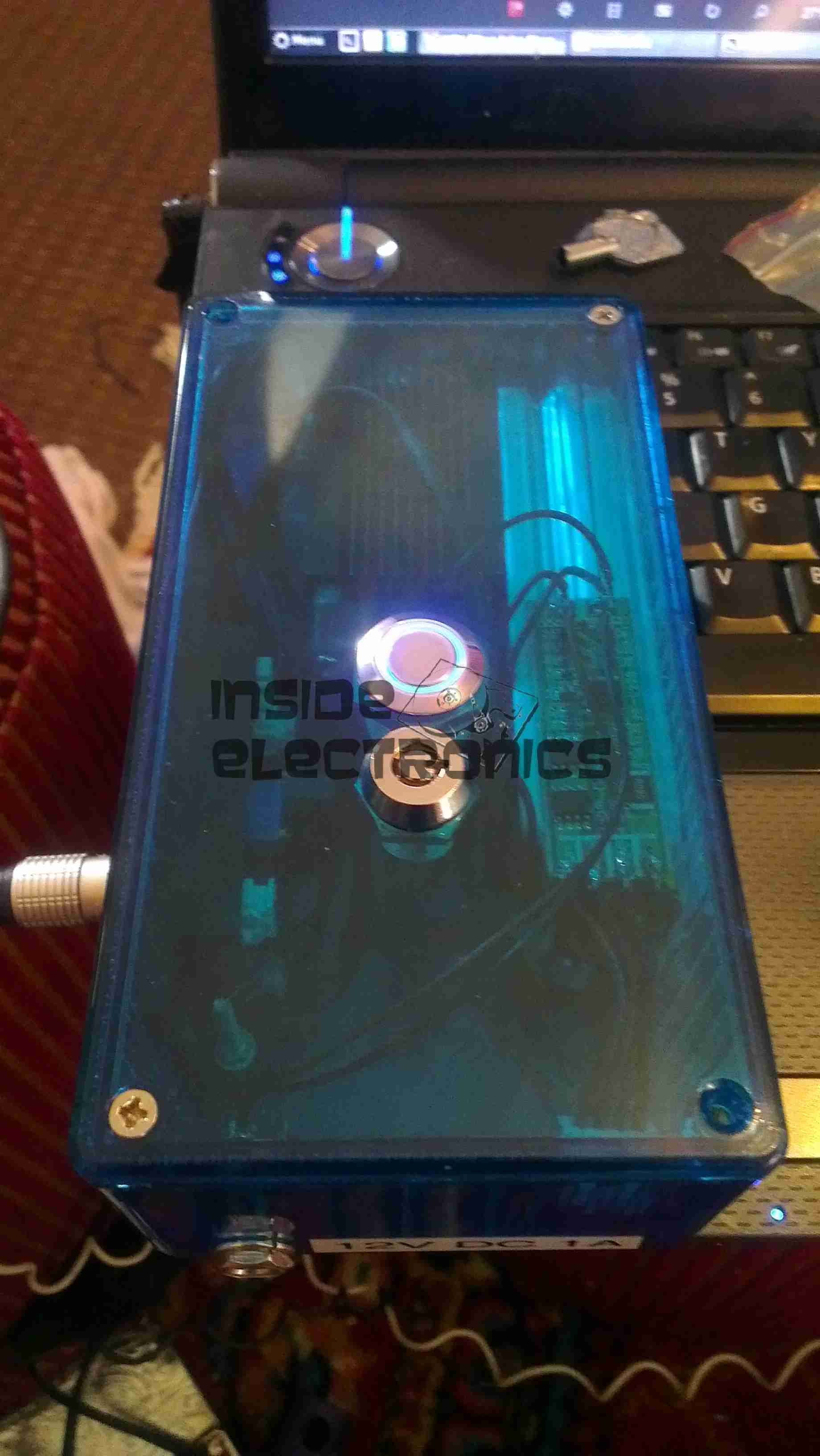
When armed, the ring around the push button illuminates blue, as a warning that the unit is armed.
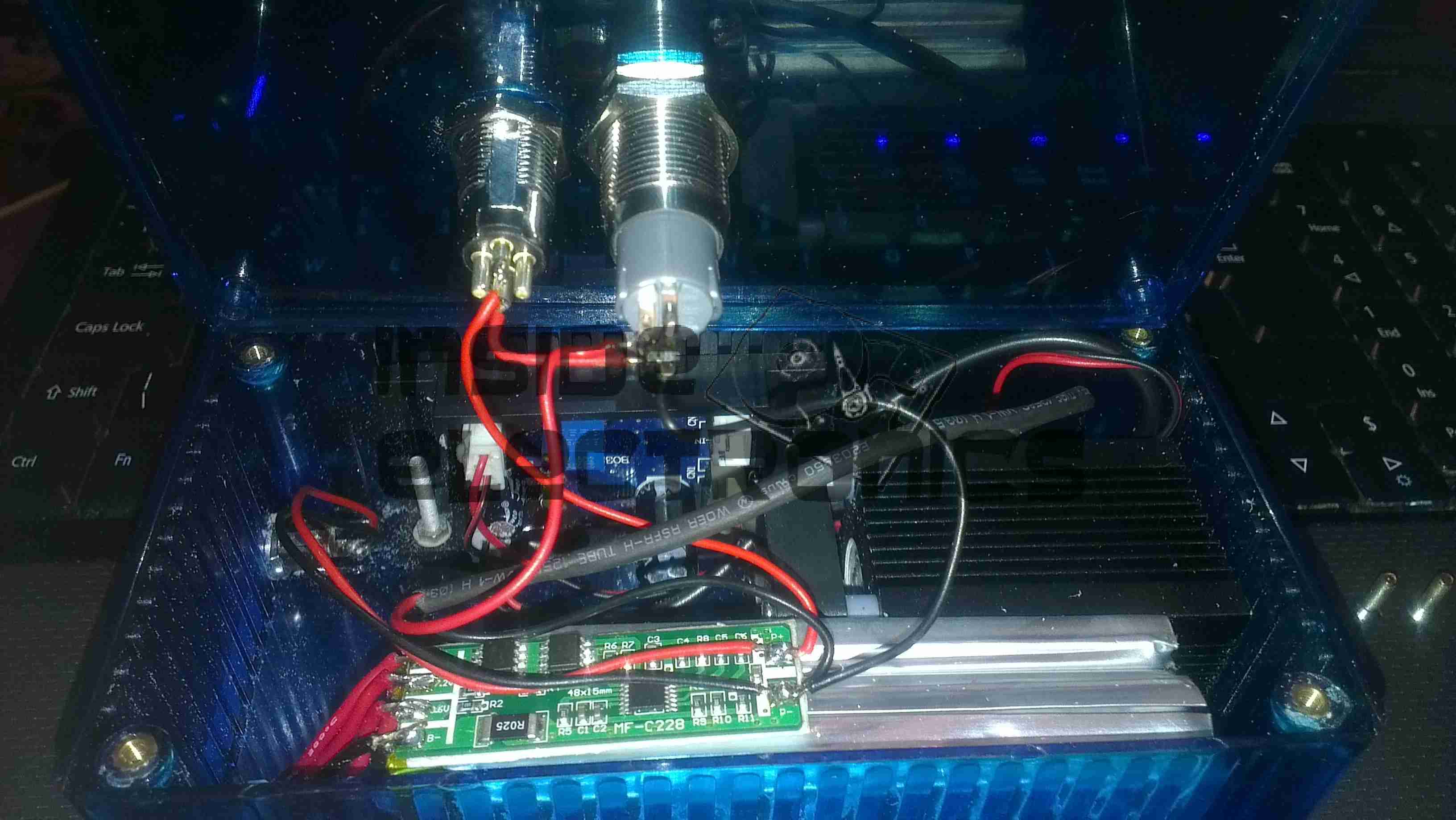
Inside the unit. The Li-Poly battery pack is at the bottom, with it’s protection & charging circuitry on the top. The switches are wired in series, with the LED connected to illuminate when the keyswitch is turned to the ON position.
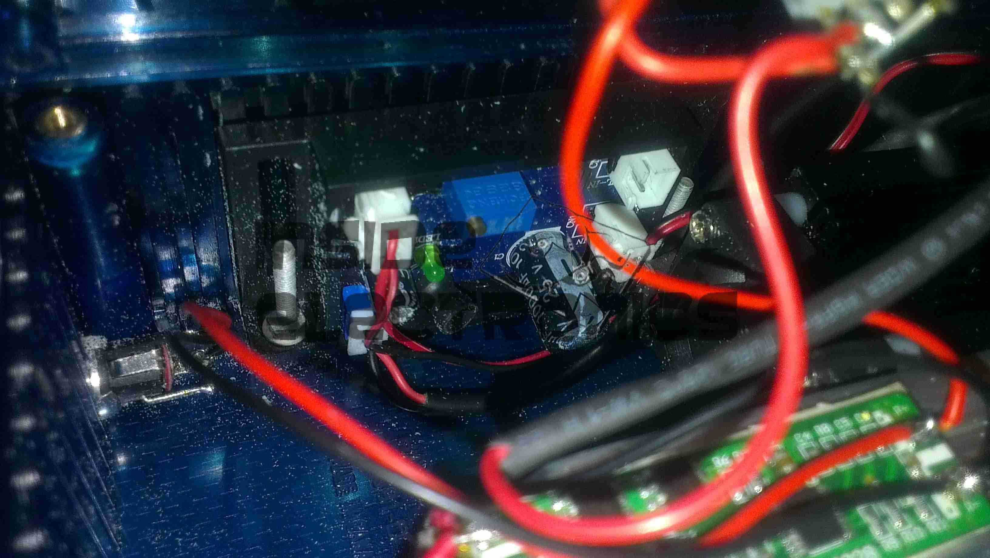
The push button applies power to the laser driver module, which regulates the input power to safely drive the semiconductor laser in the aluminium heatsink housing.

Here are a few details of a valve amplifier I am building, using the valve related parts from a 1960’s reel to reel tape recorder.
This amplifier is based on an a Mullard ECL82 triode/pentode valve, with an EM84 magic eye tube for level indication.

Here the first components are being soldered to the tags on the valve holder, there are so few components that a PCB is not required, everything can be rats-nested onto the valve holders.

Progressing with the amplifier section componentry, all resistors are either 1/2W or 2W.

Here the valve holders have been fitted, along with the output transformer, DC smoothing capacitor & the filament wiring, into the top of the plastic housing. At this point all the components that complete the amplifier section are soldered to the bottom of the right hand valve holder.

Starting the wiring between the valves & the power supply components. The volume control pot is fitted between the valve holders.

The valves here are test fitted into their sockets, the aluminium can at the back is a triple 32uF 250v electrolytic capacitor for smoothing the B+ rail.

First test of the amplifier, with the speaker from the 1960’s tape recorder from which the valves came from. the 200v DC B+ supply & the 6.3v AC filament supply is derived from the mains transformer in the background.

Here the magic eye tube has been fitted & is getting it’s initial tuning to the amplifier section. This requires selecting combinations of anode & grid resistors to set the gap between the bars while at no signal & picking a coupling RC network to give the desired response curve.

Here both valves are fitted & the unit is sitting on it’s case for final audio testing. the cathodes of the ECL82 can be clearly seen glowing dull red here.
In the final section, I will build a SMPS power supply into the unit to allow it to be powered from a single 12v DC power supply.
