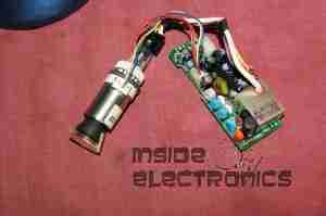
Here are the viewfinder electronics from a 1984 Hitachi VHS Movie VM-1200E Camcorder. These small CRT based displays accept composite video as input, plus 5-12v DC for power.

Here is the front face of the CRT, diameter is 0.5″.
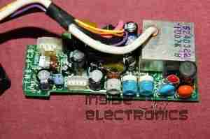
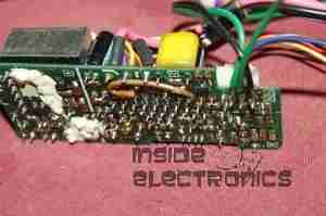
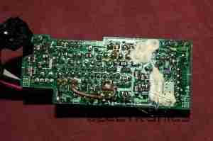
Closeup view of the PCB, there are several adjustments & a pair of connectors. Socket in the upper left corner is the power/video input. Pinout is as follows:
- Brown – GND
- Red – Video Input
- Orange – +12v DC
- Yellow – Record LED
- H. ADJ
- V. ADJ
- BRIGHT
- FOCUS
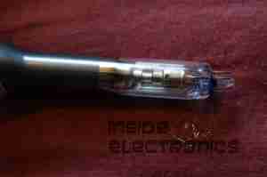
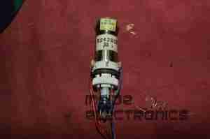
Closeup view of the CRT neck, showing the electron gun assembly.
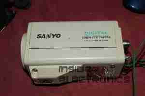
The old CCTV camera used to feed a composite signal to the CRT board. Sanyo VCC-ZM300P.
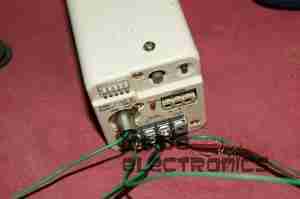
Connections at the back of the camera. Red & Black pair of wires lead to 12v power supply, Green & Black pair lead to the CRT board’s power pins. Seperate green wire is pushed into the BNC video connector for the video feed. video ground is provided by the PSU’s ground connection.
Finally the connections at the CRT drive board, left to right, +12v, Video, GND.
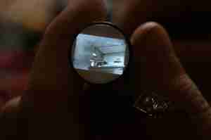

Awesome! Got mine to work too!
Hi Ryan,
Good to know! These little CRT based viewfinder modules are very simple to get going, I’ve got another CRT based post coming up as well. I seem to have become quite the expert in getting a modern signal into ancient display tech 😉
Glad you found the info here useful.
de 2E0GXE
I just got another EVF from a really low end camcorder, I don’t know what brand, but the five wire connector you have in the other write up, the one that is modified to use the LED ground, is more complicated than this new one. The gun has model number M01KKX07WB20. It only has four wires at the jumper so so far I have been using the ground for both power and video.
I was into electronics as a kid but have jumped back in head first in the last few months. Currently building a synthesizer with a Sony Watchman CRT as an oscilloscope.
And, after removing the fittings that go on the cart screen (rubber, plastic, the little rectangular frame cut out, this CRT is a few mm smaller than the other one.
Should read CRT. My calipers say 16.85mm….nevermind
I was preemptive with my comment and I can get the gun to power up but no composite video.
Hi Ryan
Without knowing what camera this new viewfinder CRT came from can’t be that helpful. If you could find a service manual it may contain schematics giving the wiring arrangements. Failing that look up the driver IC, if there’s a datasheet available for that it would be a simple matter of tracing out the connections, the circuitry in these viewfinder units is usually quite simple, you can cross reference with the schematics I have uploaded here of the various types, many things will be very similar. If you need some further help you can send me a message via the contact page & I’ll E-Mail you, that way you can send some photos.
The Watchman CRT scope synth sounds interesting. I’d definitely like to see some photos of that 🙂
de 2E0GXE
I got it to work. Found the IC datasheet and probed around until I found it. I made a bad assumption that the coax using two spots on the jumper was the video and ground. It was ground, but video was another pin I found via the data sheet.
It’s all back in its enclosure, has an RCA for video in and a USB for power. Now I have a very small portable mini TV with no sound…yet.
Thanks again, I really like your page and look forward to your new projects.
Ryan
One of those what the colors of the wires what makes function
Hi Duane,
The pinout is listed in the post, but this assumes you have this exact viewfinder module. They are all different.