Having been a user of ownCloud for a long while, I decided to jump ship to the fork NextCloud for a few reasons, but the main one is that I never managed to get ownCloud to update itself (with the built-in updater app in the Admin panel) without completely shitting the bed, and as a result having to start from scratch & reupload all my files.
Nextcloud on the other hand has managed a major upgrade without any such problems, and the developers seem to be much more active than the ownCloud devs at present.
The one issue at the moment is that there are no packages for the Linux desktop client – it has to be built from scratch. This isn’t too difficult though, but to make things even easier I’ve thrown together a little bash script to automate the process. It’s tested to work under the latest version of Linux Mint (18.1), and does use a couple of commands that sudo won’t allow, so has to be run as root. It’s not polished in any way, but does work fine!
After the build process has completed, the client itself can be run from the Terminal, or made to run at system boot via the Startup Applications Editor in Linux Mint.
#!/bin/bash

echo "This script will compile & install Nextcloud Desktop Sync Client"
echo "Please be patient, this will take a while"

if [[ $EUID -ne 0 ]]; then
   echo "Root commands are used by this script, please run as root user to avoid errors"
   exit 1
fi

echo ""
echo "Installing Build Tools..."
echo ""
apt-get install cmake git-core -y

echo ""
echo "Cloning GitHub Repo..."
echo ""
git clone https://github.com/nextcloud/client_theming.git
cd client_theming
git submodule update --init --recursive

echo ""
echo "Adding Xenial Source Repos to /etc/apt/sources.list..."
echo ""

echo "deb-src http://archive.ubuntu.com/ubuntu/ xenial universe" >> /etc/apt/sources.list
echo "deb-src http://archive.ubuntu.com/ubuntu/ xenial-updates universe" >> /etc/apt/sources.list

echo ""
echo "Updating Apt & installing build dependencies..."
echo ""

apt-get update
apt build-dep owncloud-client -y

echo ""
echo "Compiling NextCloud Client..."
echo ""

mkdir build-linux
cd build-linux
cmake -D OEM_THEME_DIR=`pwd`/../nextcloudtheme ../client
make
make install

echo ""
echo "Adding Custom Library Directory Config..."
echo ""

echo "/usr/local/lib/x86_64-linux-gnu" >> /etc/ld.so.conf.d/x86_64-linux-gnu.conf
ldconfig

echo ""
echo "Nextcloud Client has been built & installed!"
echo ""
exit 0
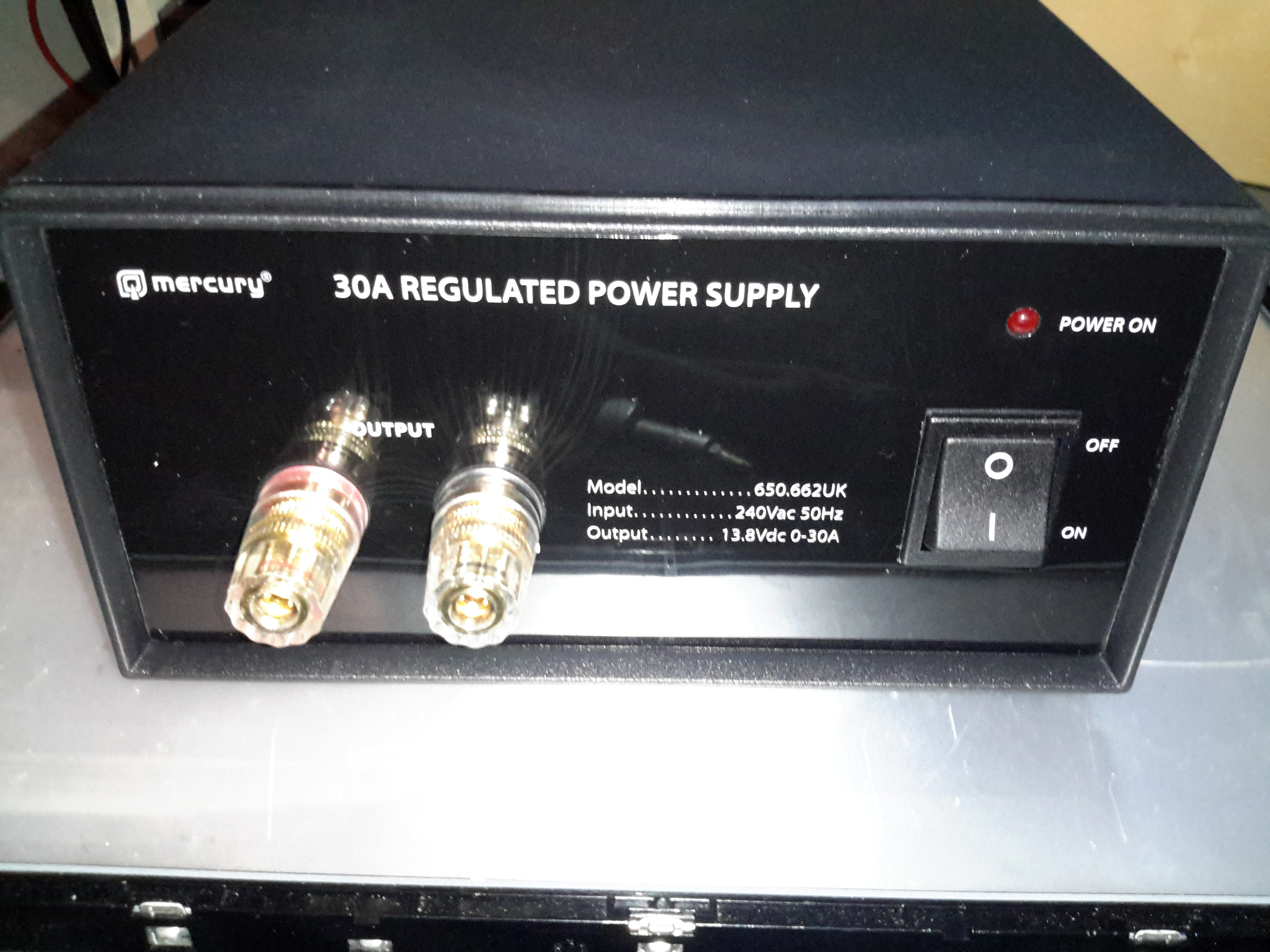
After having a couple of the cheap Chinese PSUs fail on me in a rather spectacular fashion, I decided to splash on a more expensive name-brand PSU, since constantly replacing PSUs at £15 a piece is going to get old pretty fast. This is the 30A model from Mercury, which seems to be pretty well built. It’s also significantly more expensive at £80. Power output is via the beefy binding posts on the front panel. There isn’t any metering on board, this is something I’ll probably change once I’ve ascertained it’s reliability. This is also a fixed voltage supply, at 13.8v.
Rear Panel
Not much on the rear panel, just the fuse & cooling fan. This isn’t temperature controlled, but it’s not loud. No IEC power socket here, the mains cable is hard wired.
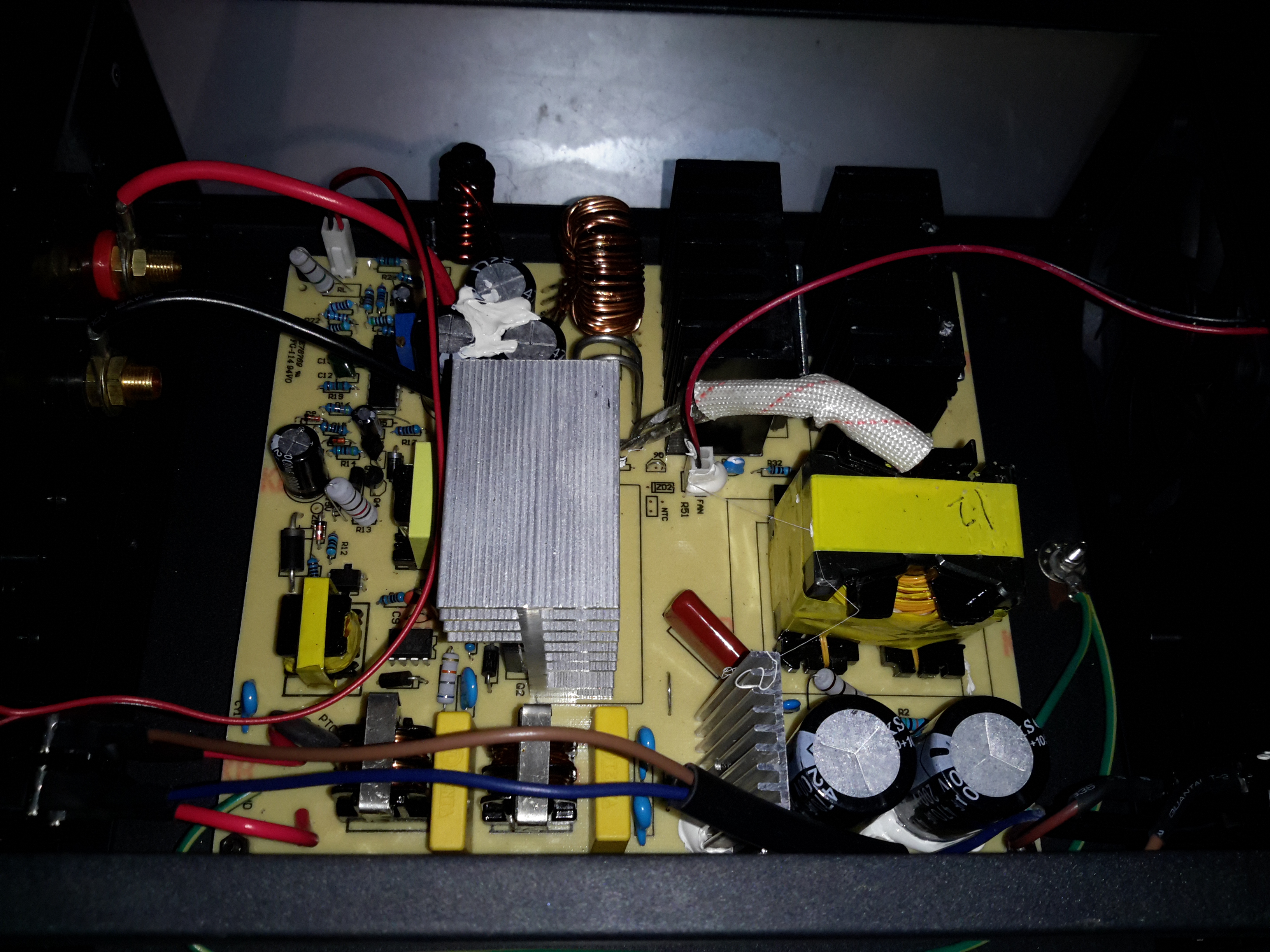
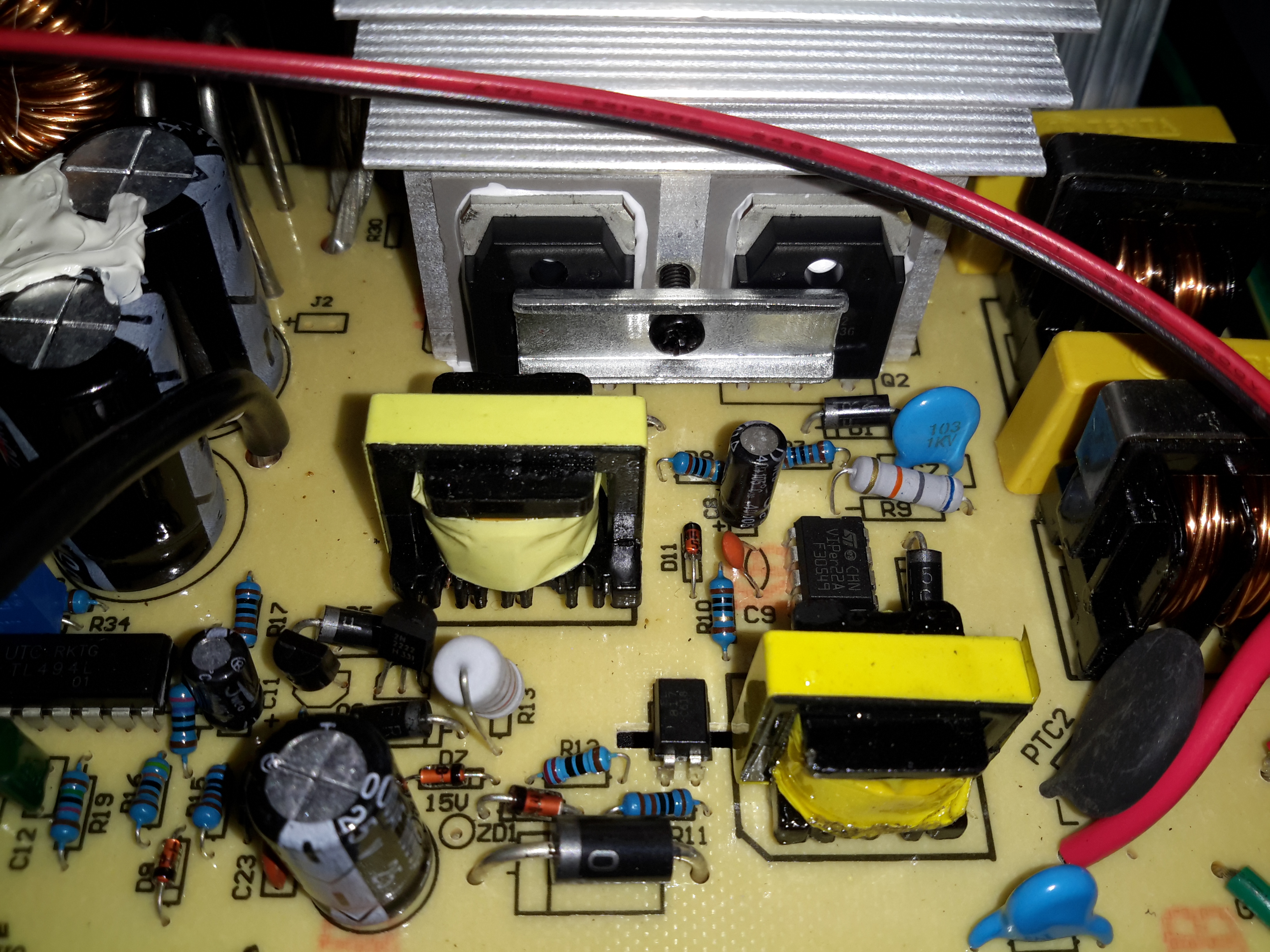
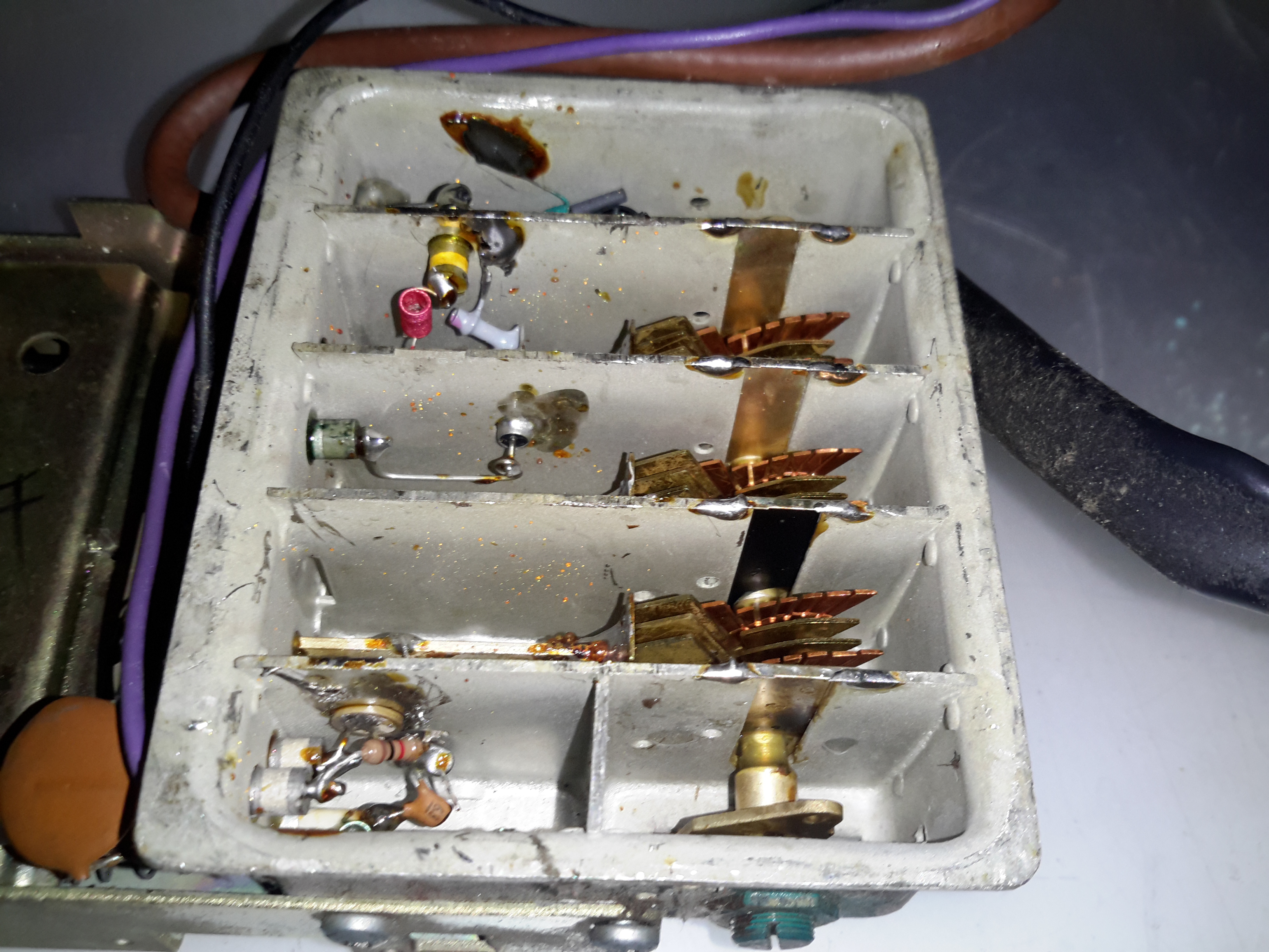
Main Board
Removing some spanner-type security screws reveals the power supply board itself. Everything on here is enormous to handle the 30A output current at 13.8v. The main primary side switching transistors are on the large silver heatsink in the centre of the board, feeding the huge ferrite transformer on the right.
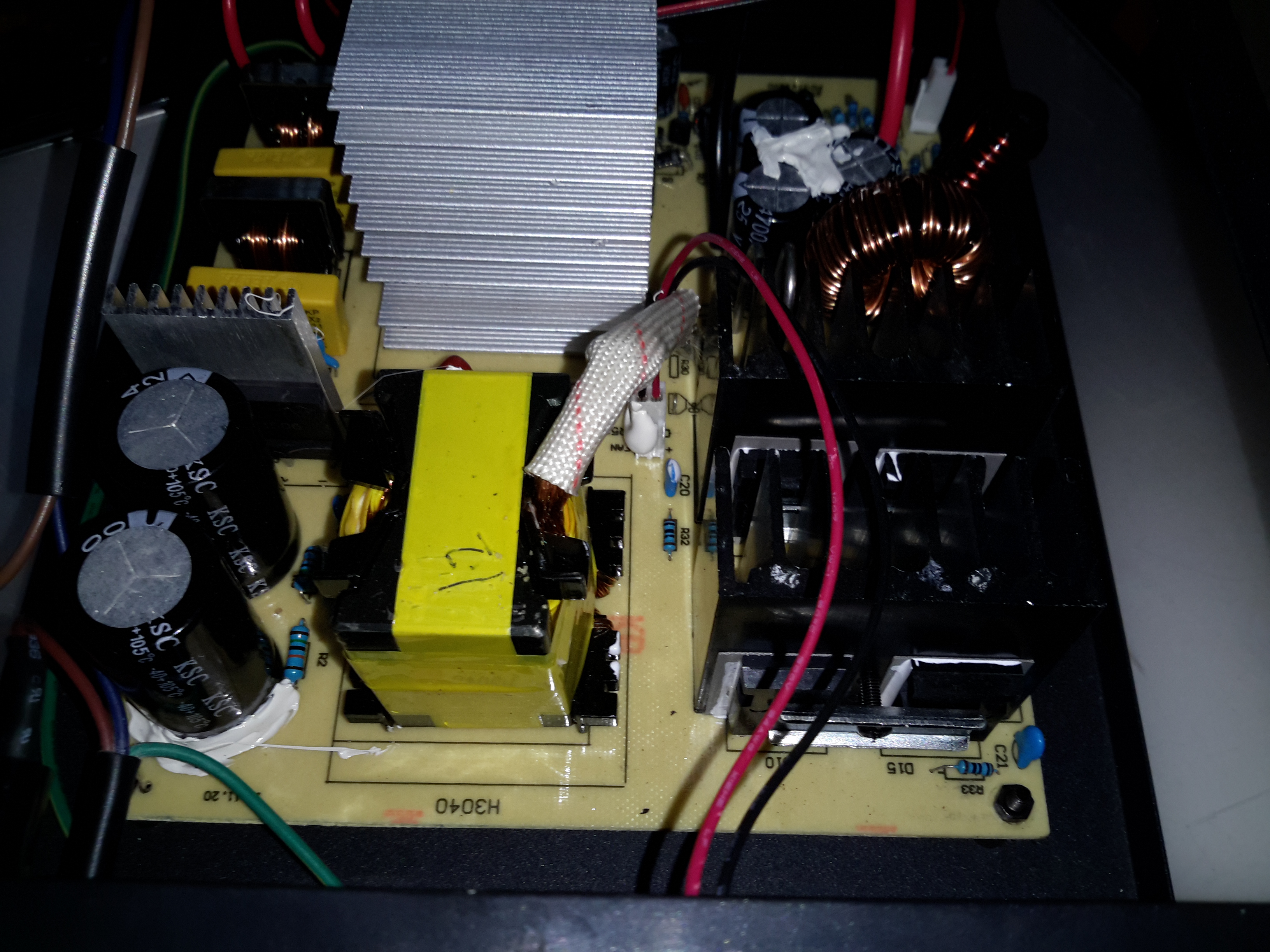
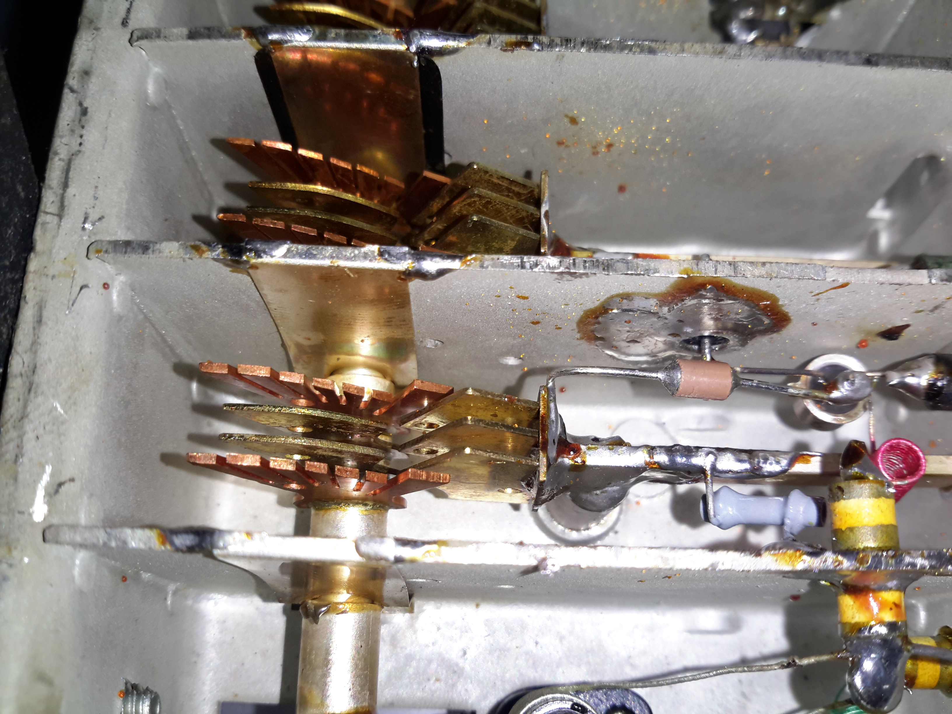
Transformer
The transformer’s low voltage output tap comes straight out instead of being on pins, due to the size of the winding cores. Four massive diodes are mounted on the black heatsinks for output rectification.
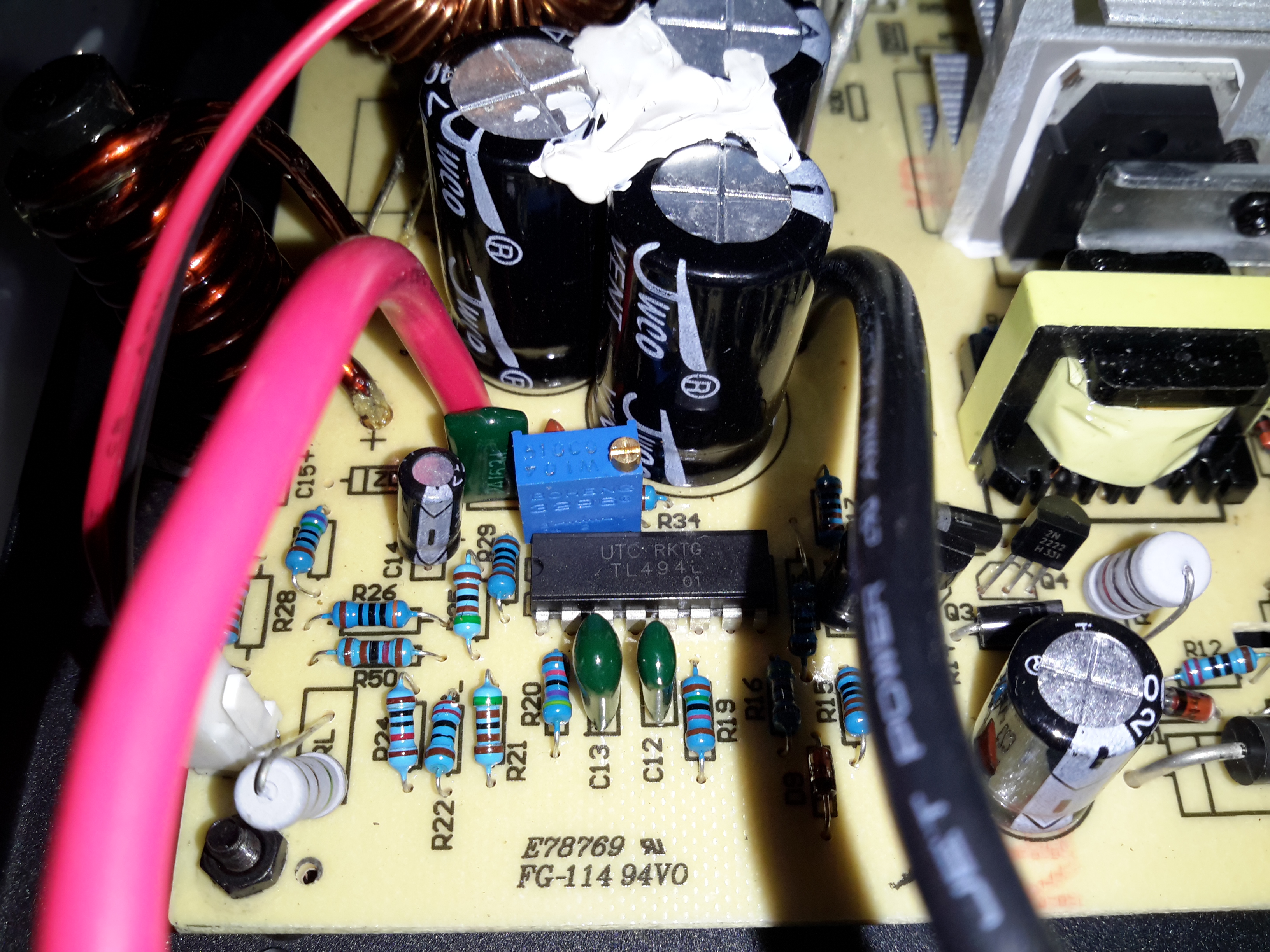
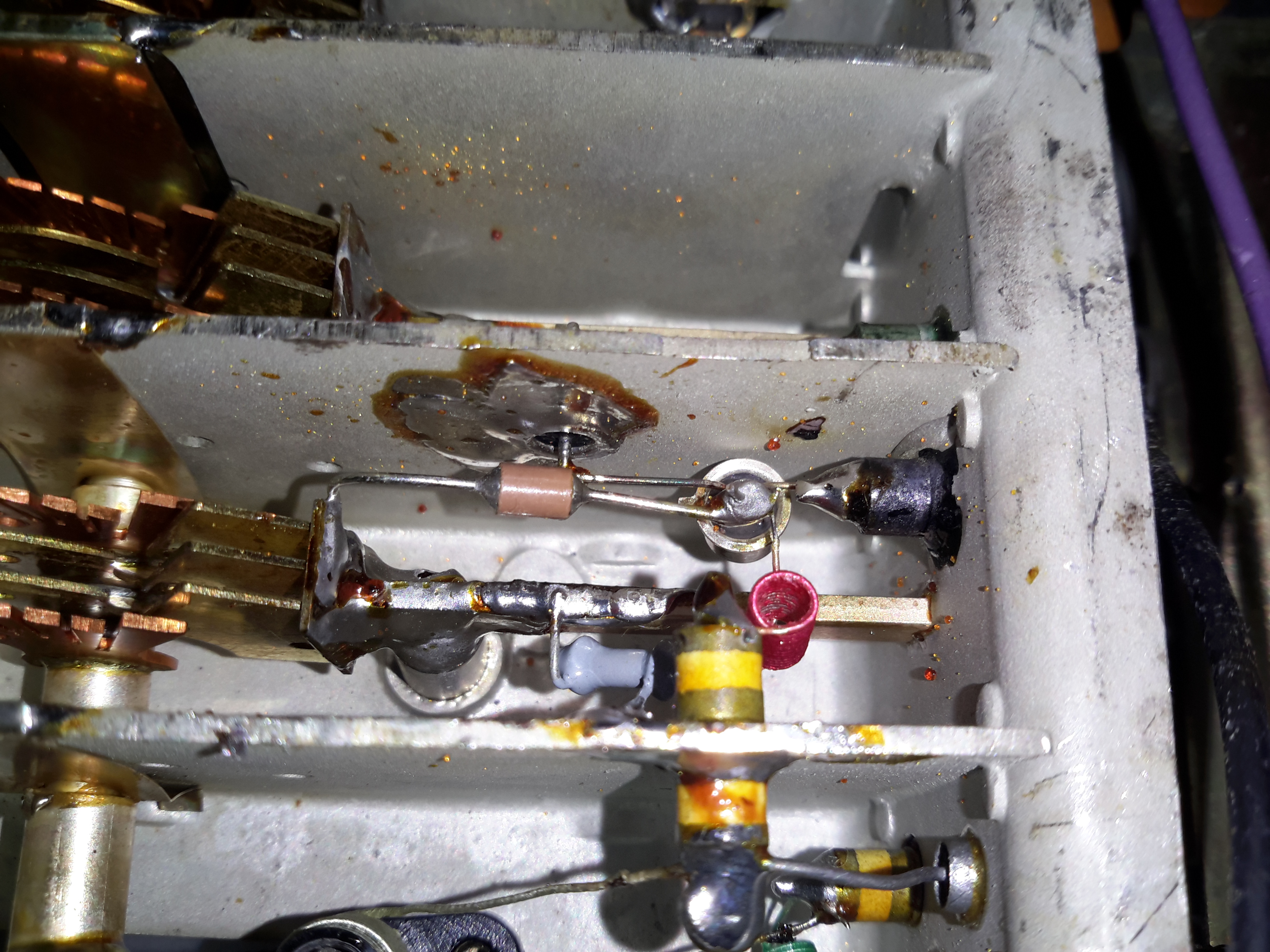
SMPS Controller
The supply is controlled via the jelly bean TL494 PWM controller IC. The multi-turn potentiometer doesn’t adjust the output voltage, more likely it adjusts the current limit.
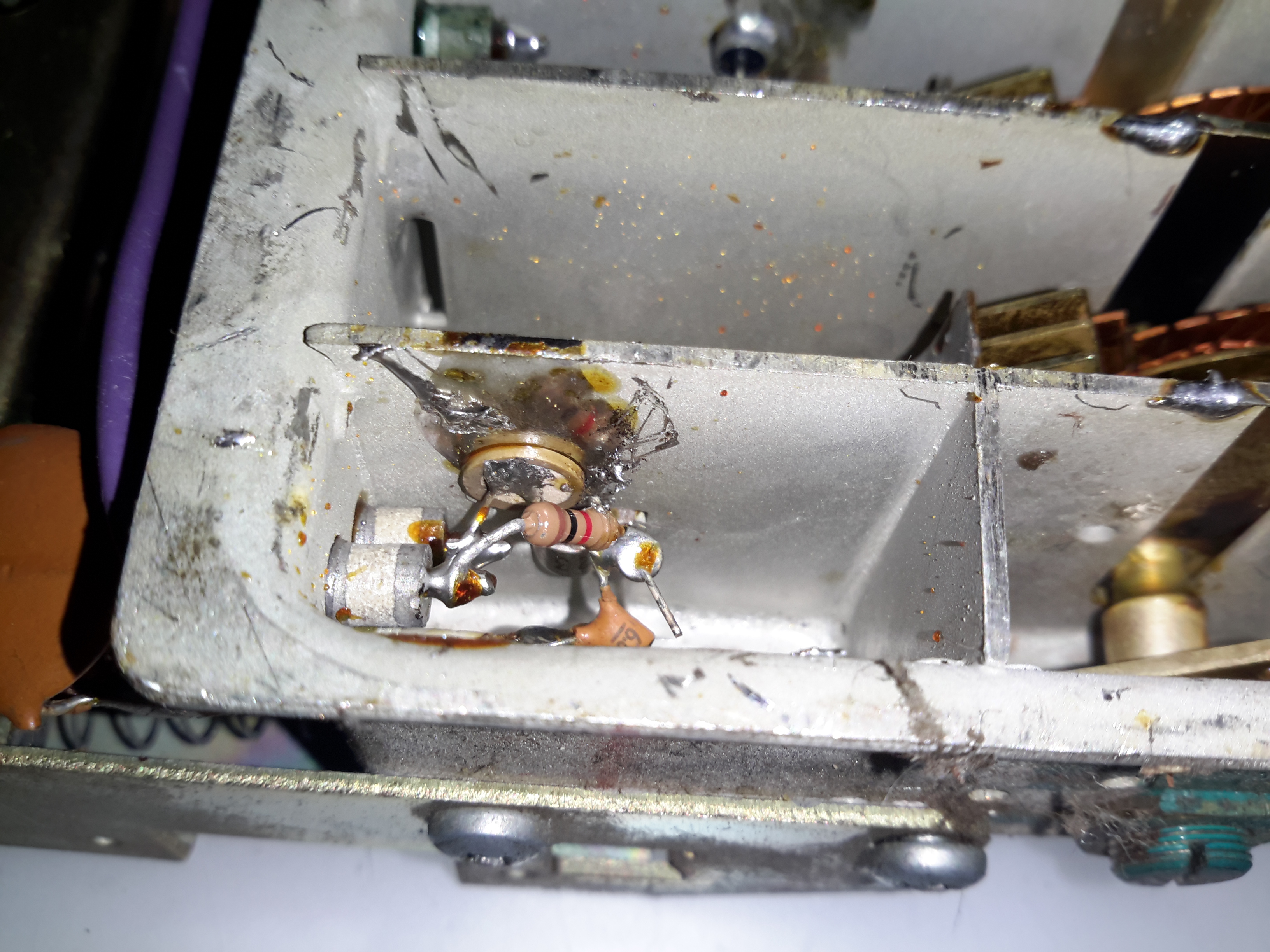
Standby Supply
Power to initially start the supply is provided by a small SMPS circuit, with a VIPer22A Low Power Primary Switcher & small transformer on the lower right. The transformer upper left is the base drive transformer for the main high power supply.
In a word, no they aren’t any good. As usual, cheap doesn’t equal good, and in this case the cheapo clones are a total waste of money. Read on for the details!
I’ve been looking into using a cheap Chinese clone Honda GX35 engine to drive an automotive alternator as a portable battery charging & power unit. These engines are available very cheaply on eBay, aimed at the mini-bike/go-kart market.
For those not in the know, the Honda GX25/35 4-strokes are strimmer-type engines that traditionally were always of 2-stroke construction. Honda worked out how to have a wet-sump engine without the need to keep the engine always in the “upright” position. They do not require mixing of oil into the fuel for lubrication as 2-strokes do, so should be much cleaner running.
So far I’ve had two of these cheap engines, as the first one died after only 4 hours run time, having entirely lost compression. At the time the engine was idling, no load, having been started from cold only a few minutes before. Having checked the valve clearances to make sure a valve wasn’t being held partially open, I deduced that the cause was broken piston rings. This engine was replaced by the seller, so I didn’t get a chance to pull it to bits to find out, but I decided to do a full teardown on the replacement to see where the cloners have cut corners.
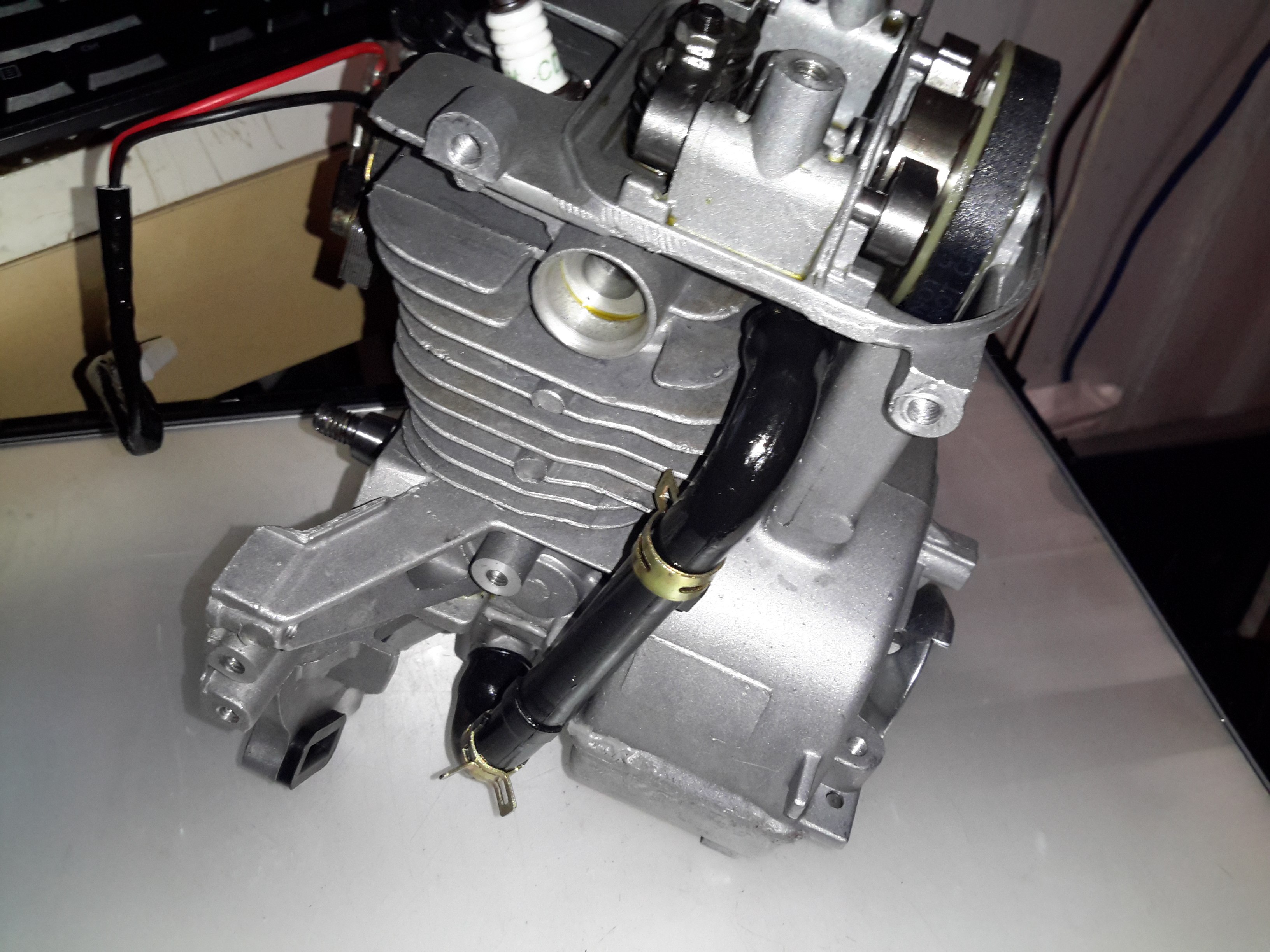
Oil Return Hose
I’ve already stripped off the ancillary components: exhaust, carburettor, fuel tank, cowlings, as these parts are standard to any strimmer engine. The large black hose here is the oil return feed back to the rocker cover from the crankcase. The oiling system in these engines is rather clever. The main engine block is made of light alloy, probably some permutation of Aluminium. There is much flashing left behind between the cylinder fins from the die-casting process, and not a single engine manufacturer’s logo anywhere. (From what I’ve read, the genuine Honda ones have their logo on the side of the crankcase).
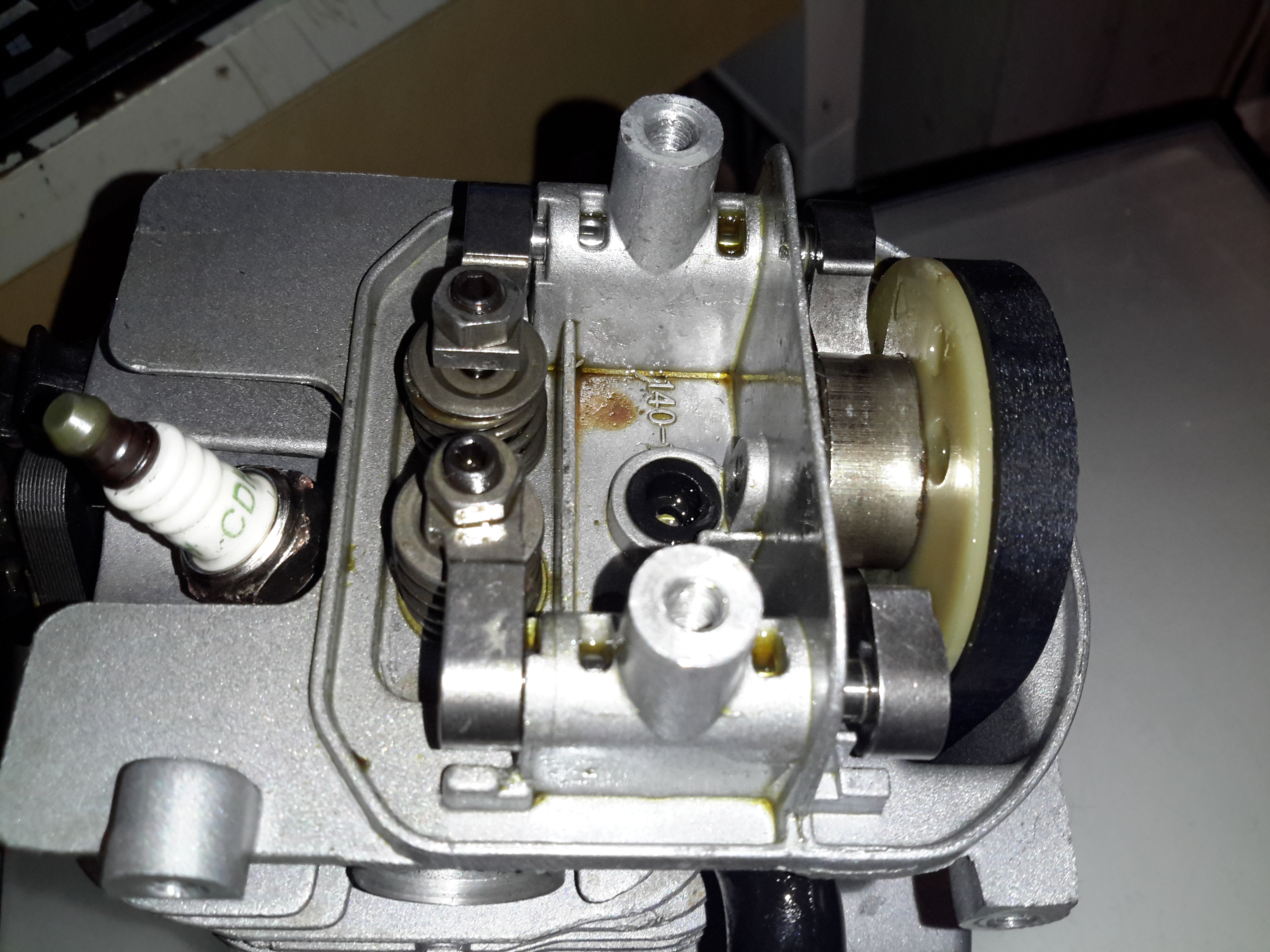
Rocker Box
Here’s the top of the engine with valves, rockers & camshaft. All the valve gear up here, minus the valves themselves & springs, are manufactured from sintered steel, there are no proper “bearings”, the steel shafts just run in the aluminium castings. The cam gear is of plastic, with the sintered steel cam pressed into place. The cam also has the bearing surface for the pin that the whole assembly rotates on. The timing belt runs in the oil & is supposed to last the life of the engine, and while I’d believe that in the original Honda, I certainly wouldn’t in this engine. The black grommet is the opening of the oil return gallery.
Cam
Here’s the cam on the back of the plastic pulley. A single cam is used for both intake & exhaust valves for space & simplicity.
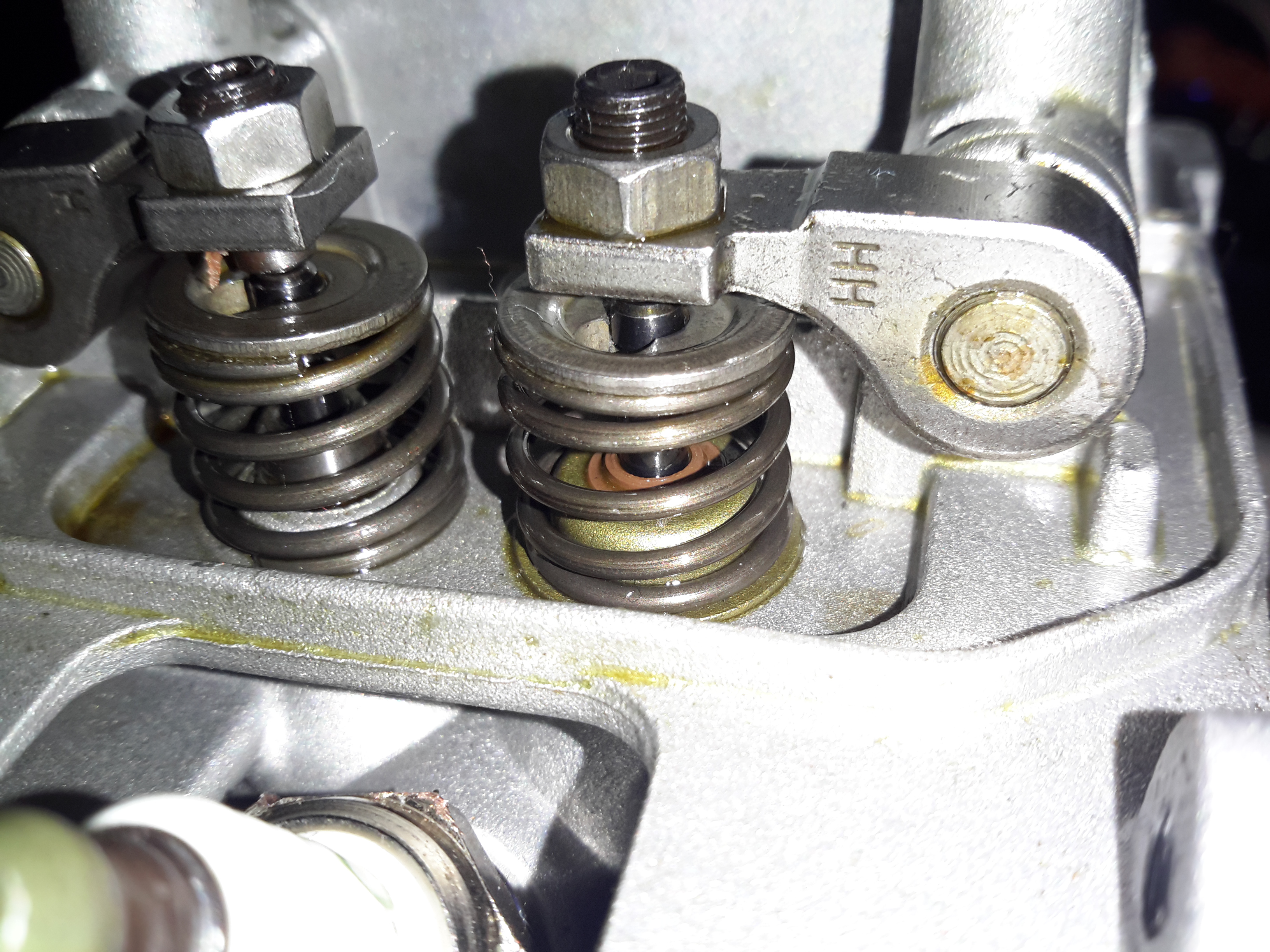
Intake Valve Stem Seal
Just visible under the intake valve spring is a simple stem seal, to hopefully prevent oil being sucked down the valve guide into the cylinder by intake vacuum. Running these cheap engines proves this seal to be ineffective, as they blow about as much blue oil smoke as a 2-stroke when they’re started cold. 😉
Starter Side
The starter side is where the oil sump is located on these engines, along with the dipstick.
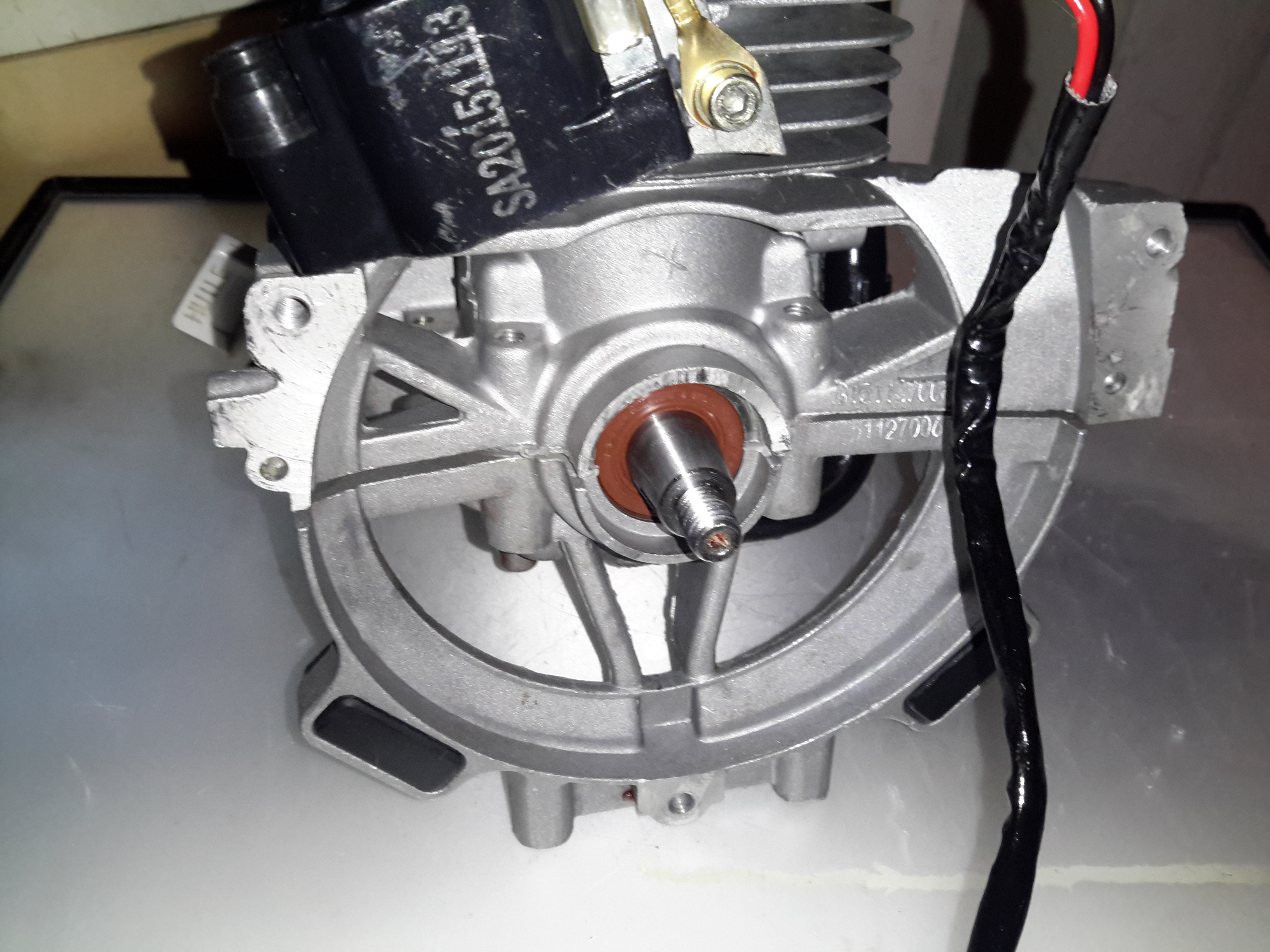
Flywheel Side
The flywheel end of the engine is the usual fare for small engines. Ignition is provided by a magneto, with a magnet in the flywheel. This is no different from the 2-stroke versions. As these ignitions fire on every revolution of the crankshaft, the spark plug fires both on compression, igniting the fuel for normal operation, and again into the exhaust stroke, where the spark is wasted.
One thing I have noticed about these engines is an almost total lack of cooling air coming through the cowling over the cylinder cooling fins. Plenty was flowing over the exhaust silencer side, I believe bad housing design would be what causes this problem. A lack of cooling certainly wouldn’t help engine longevity!
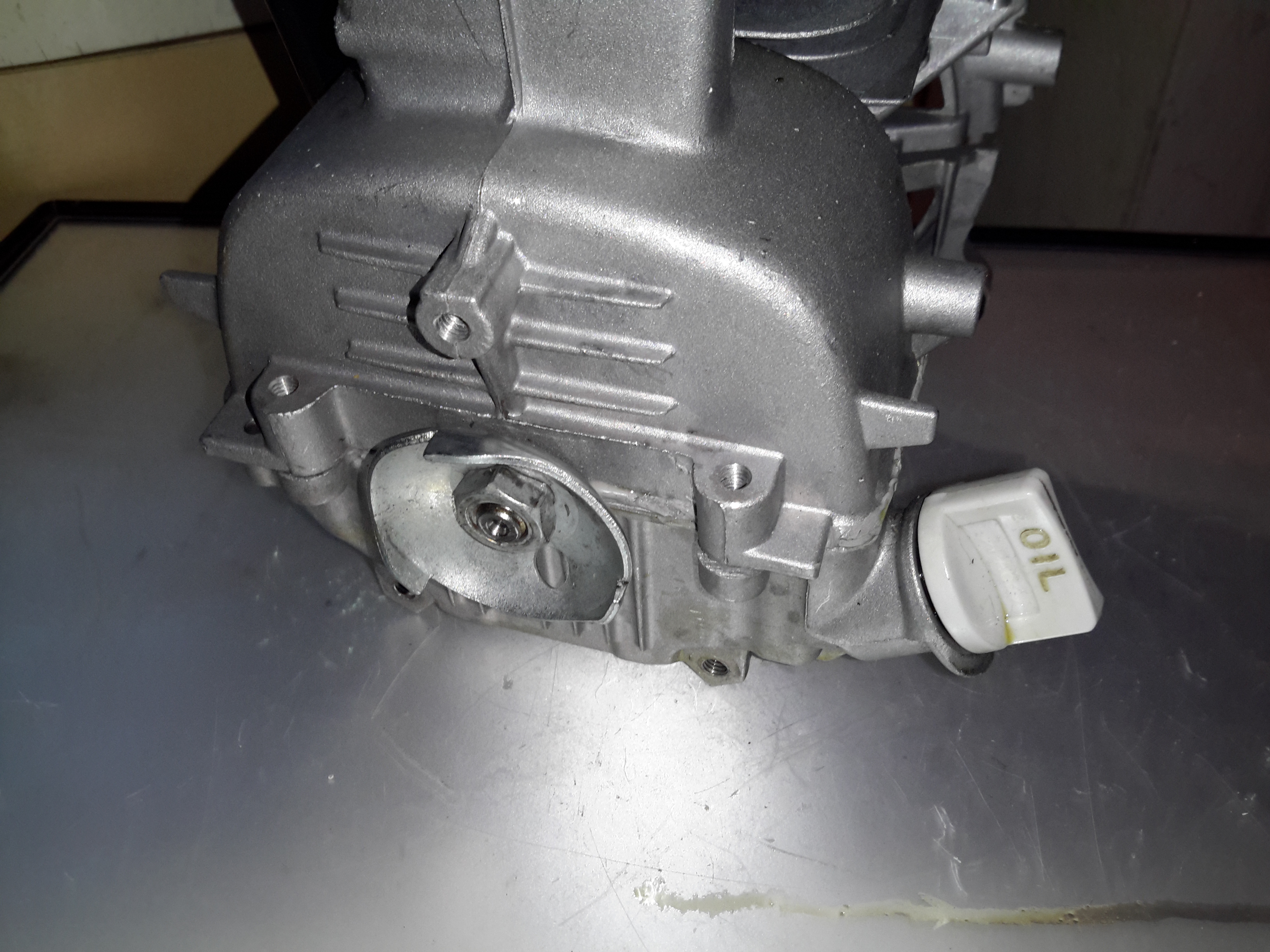
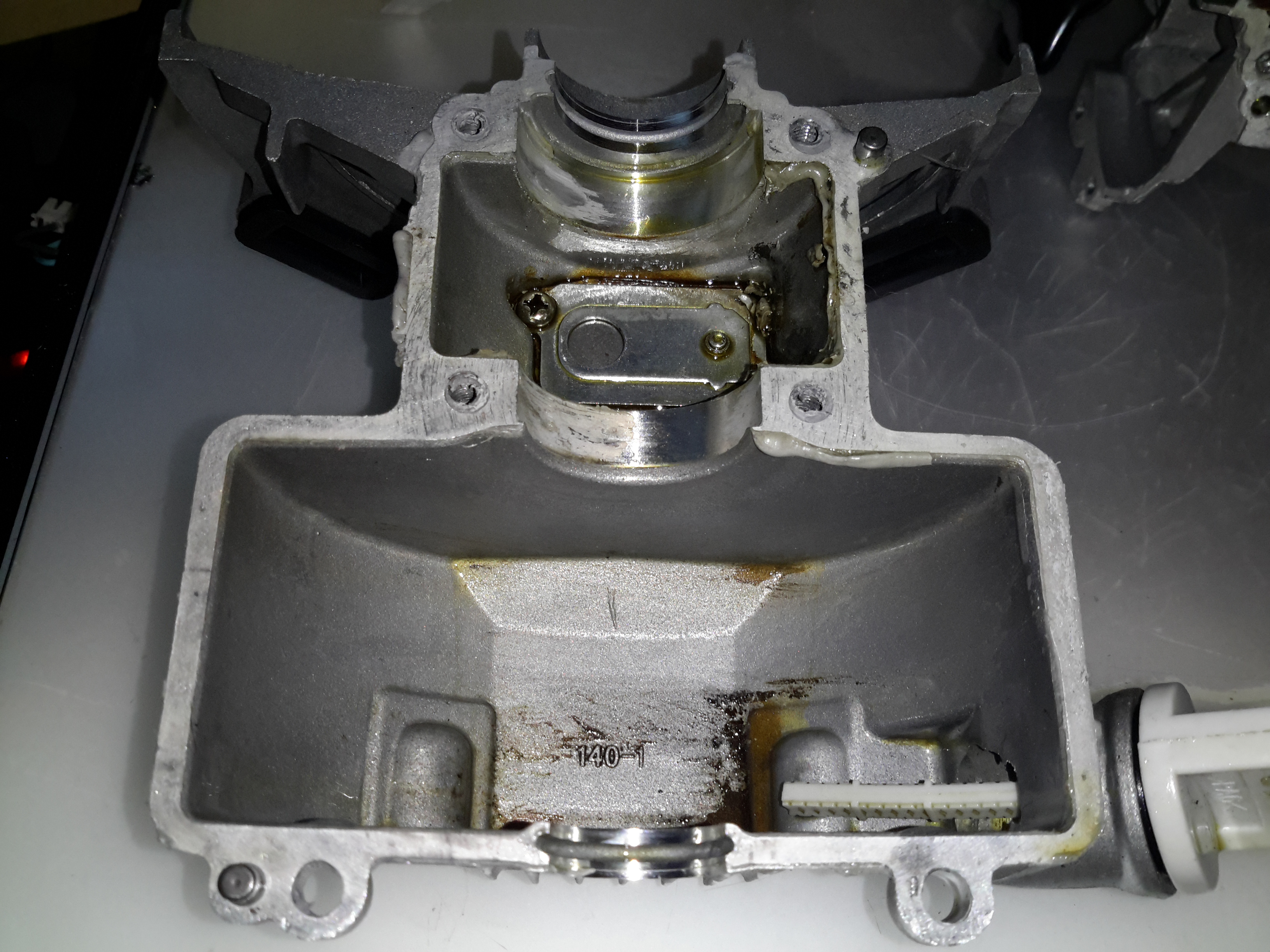
Engine “Sump”
Separating the bottom of the engine was a little difficult, as there is a significant bead of sealant used instead of a gasket. Inside the sump of the engine are a pair of paddles, which stir up the oil into a mist. As the piston moves in the cylinder, it acts as a pump, creating alternating pulses of pressure & vacuum in the crankcase. Oil mist flows through a drilling in the crank from the sump, into the crankcase where it (hopefully) lubricates the bearings & the cylinder wall. Incidentally, the only main bearings are on the crankcase – the far end of the shaft that carries the oil paddles & timing belt is just flapping in the breeze, the only support being the oil seal in the outer housing. The crank itself isn’t hardened – a file easily removes metal from all parts that I could get at. The big end journal pin might be, but these cranks are pressed together so I can’t access that part.
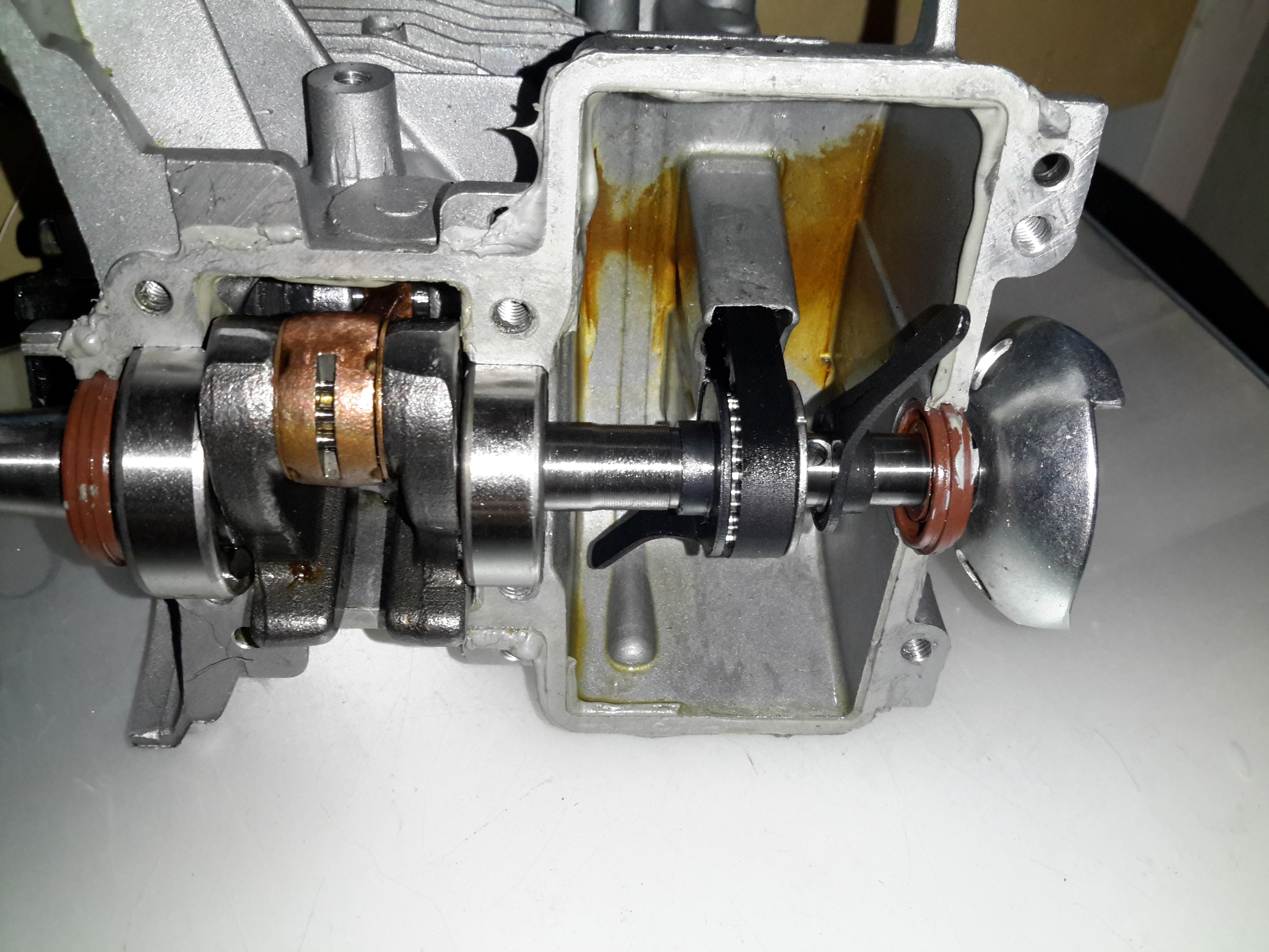
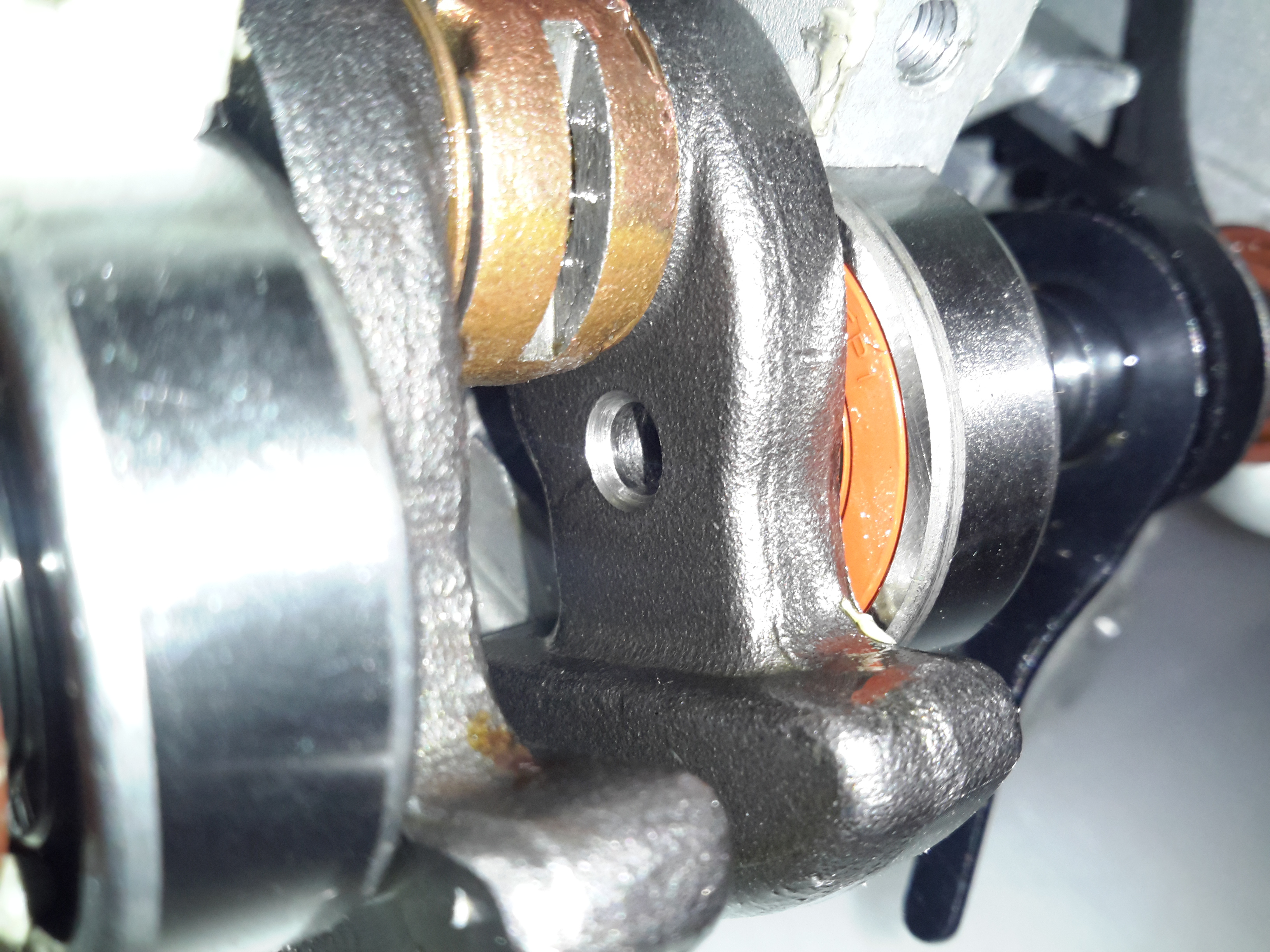
Lubrication Gallery
The oil mist feeds into the crankcase through this hollow section of shaft, there’s a drilling next to the timing belt pulley to connect the two spaces together.
Lower Crankcase
The lower crankcase is just a simple die casting, there’s a check valve at the bottom under the crankshaft to transfer oil to the rocker cover, through the rubber tube on the outside of the engine. After the oil reaches the rocker box, it condenses & returns to the sump via the timing belt cavity.
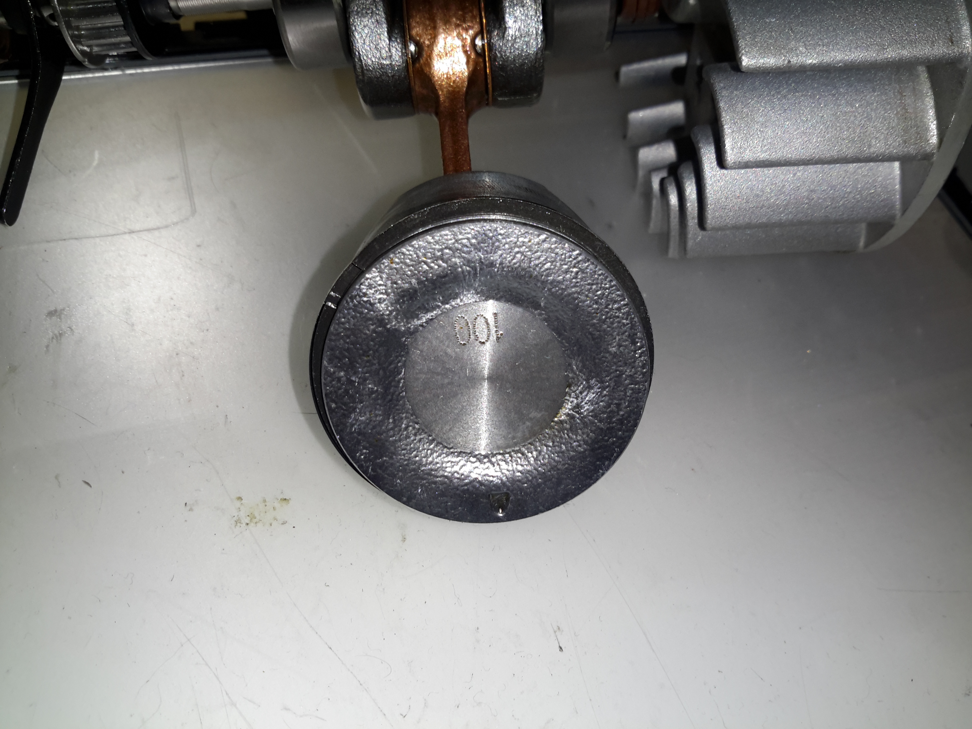
Piston Crown
Removing the crankshaft from the engine block gives me a look at the piston. The factory couldn’t even be arsed to machine the crown, it’s still got the rough finish from the hot-forging press. This bad finish will pick up much carbon from combustion, and would probably cause detonation once enough had accumulated to become incandescent in the heat of combustion. Only the centre is machined, just enough for them to stamp a number on.
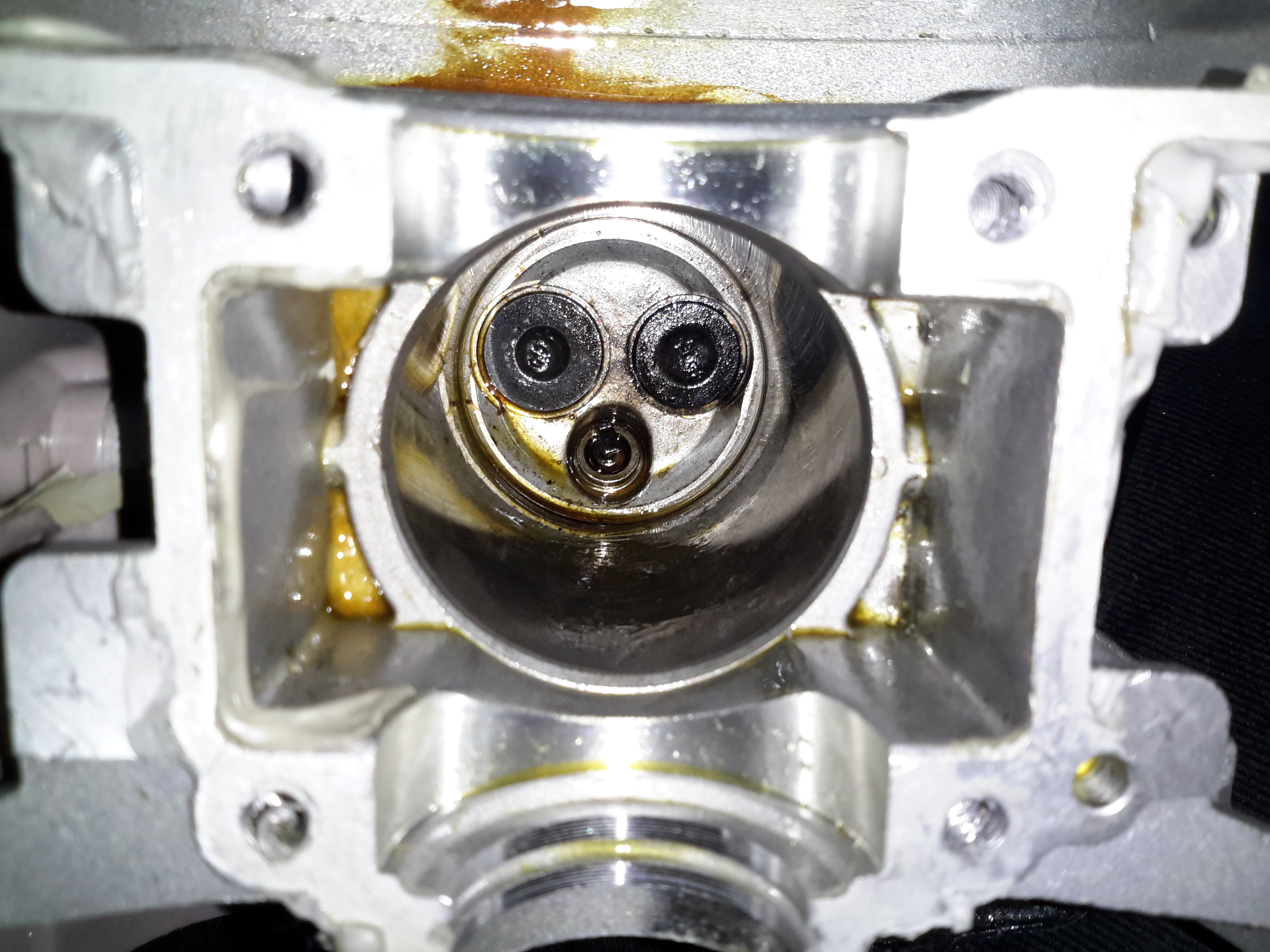
Cylinder Bore
A look up the cylinder bore shows the valves in the cylinder head. These engines, like their 2-stroke cousins have a single casting instead of a separate block & head, so getting at the valves is a little more of a pain. The cylinder bore itself is a cast-in iron liner and it’s totally smooth – like a mirror finish. There’s not a single sign of a crosshatch pattern from honing. If the first engine that died on me was the same – I’d be surprised if it wasn’t, this could easily cause ring breakage. The usual crosshatch pattern the cylinder hone produces holds oil, to better help lubricate the piston & rings. Without sufficient lubrication, the rings will overheat & expand far enough to close the end gap. Once this happens they will break.
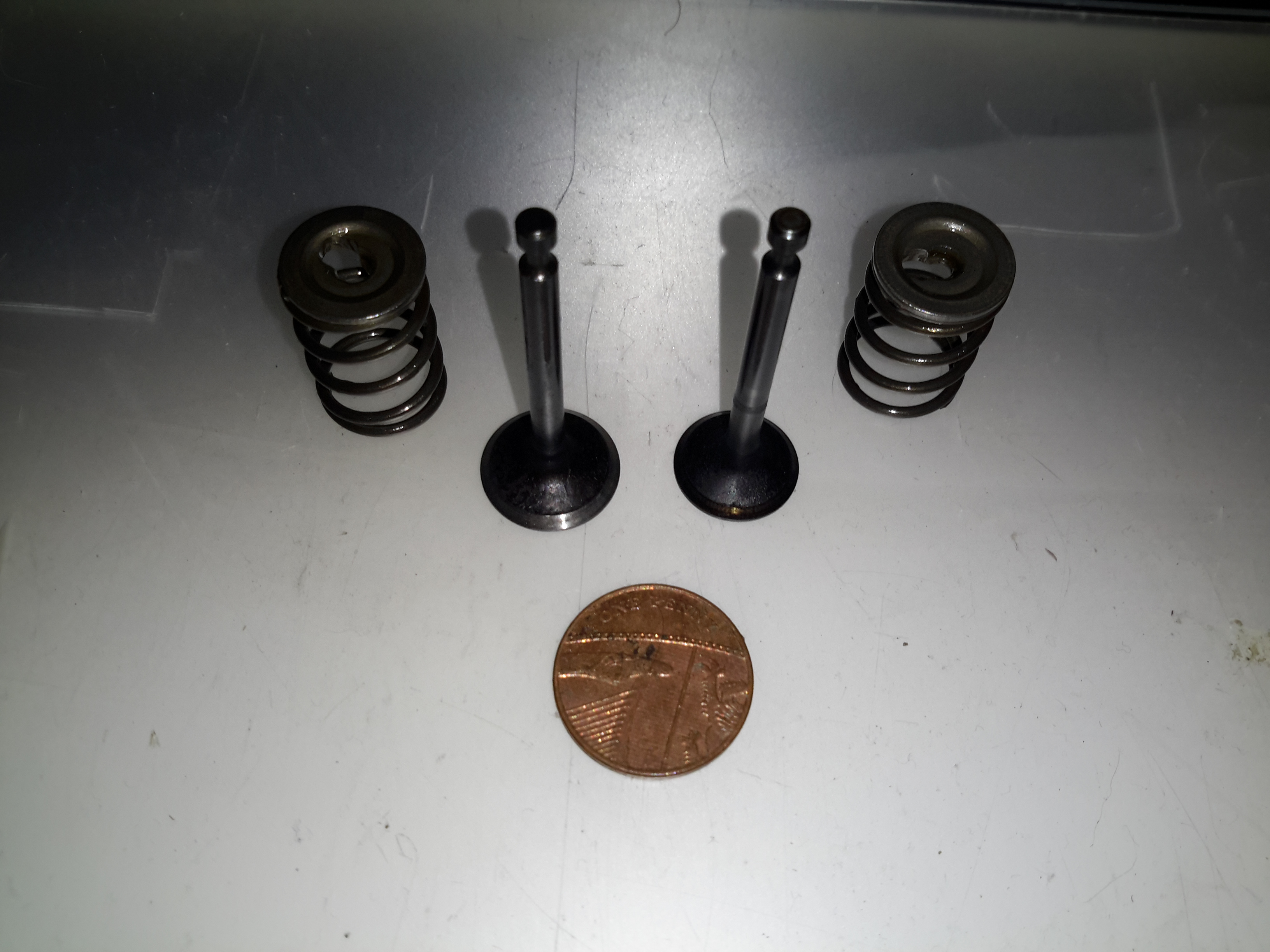
Engine Valves
Finally, here’s the valves with their springs removed from the cylinder. These are the smallest poppet valves I’ve ever seen, a British penny is provided for scale.
In all, these engines share many components with the older 2-stroke versions. The basic crankshaft & connecting rod setup is the same as I’ve seen in many old 2-strokes previous, the addition of the rather ingenious oiling system by Honda is what makes these tiny 4-strokes possible. I definitely won’t be trusting these very cheap copies in any of my projects, reliability is questionable at the least. The apparent lack of cooling air flow over the cylinder from the flywheel fan is concerning, along with the corner-cutting on the cylinder finishing process & piston crown, presumably to reduce factory costs.
I’ve been running my own VPN so I can access my home-based servers from anywhere with an internet connection (not to mention, in this day & age of Government snooping – personal privacy & increased security).
I’m on a pretty quick connection from Virgin Media here in the UK, currently the fastest they offer:
Virgin Media
To do these tests, I used the closest test server to my VPN host machine, in this case Paris. This keeps the variables to a minimum. Testing without the VPN connection gave me this:
Paris Server Speed
I did expect a lower general speed to a server further away, this will have much to do with my ISP’s traffic management, network congestion, etc. So I now have a baseline to test my VPN throughput against.
The problem I’ve noticed with OpenVPN stock configs are that the connections are painfully slow – running over UDP on the usual port of 1194 the throughput was pretty pathetic:
Stock Config Speed
I did some reading on the subject, the first possible solution being to change the send/receive buffers so they’re set to a specific value, rather than letting the system handle them. I also added options to get the server to push these values to the clients, this saving me the trouble of having to reissue all the client configurations.
Unfortunately just this option didn’t work as well as I’d like, downstream speeds jumped to 25Mb/s. In the stock config, the tunnel MTU & MSSFIX settings aren’t bothered with, some adjustment to set the tunnel MTU to lower than the host link MTU (in my case the standard 1500) prevents packet fragmentation, MSSFIX let’s the client TCP sessions know to limit the packet sizes it sends so that after OpenVPN has done the encryption & encapsulation, the packets do not exceed the set size. This also helps prevent packet fragmentation.
tun-mtu 1400
mssfix 1360
VPN Tweaked
After adjusting these settings, the download throughput over the VPN link has shot up to 136Mb/s. Upload throughput hasn’t changed as this is limited by my connection to Virgin Media. Some more tweaking is no doubt possible to increase speeds even further, but this is fine for me at the moment.
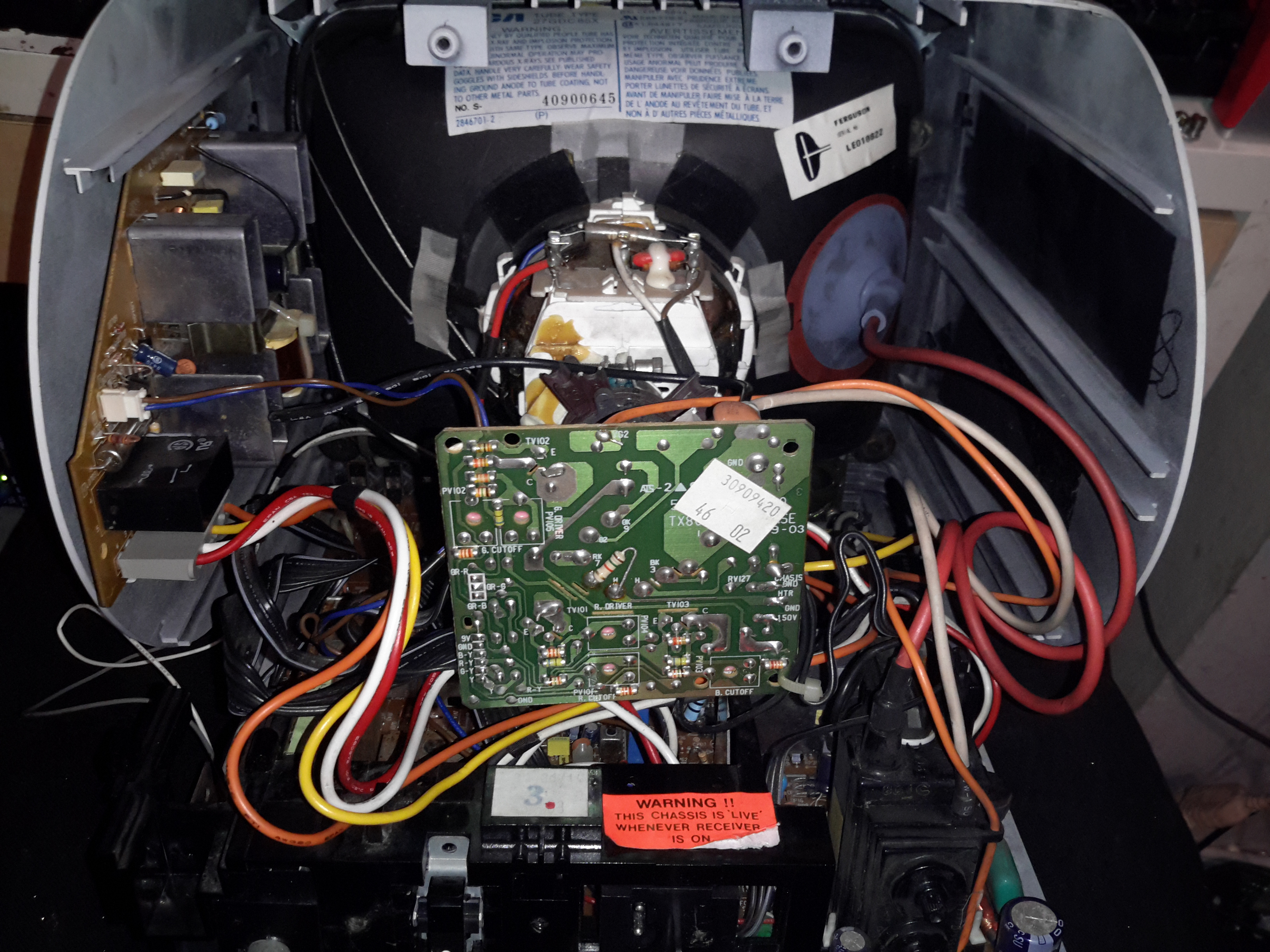
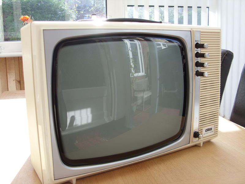
Here’s the other TV that was picked up from the local water point having been put of to be recycled. This one is much newer than the Thorn TV, a 10″ colour version from Ferguson.
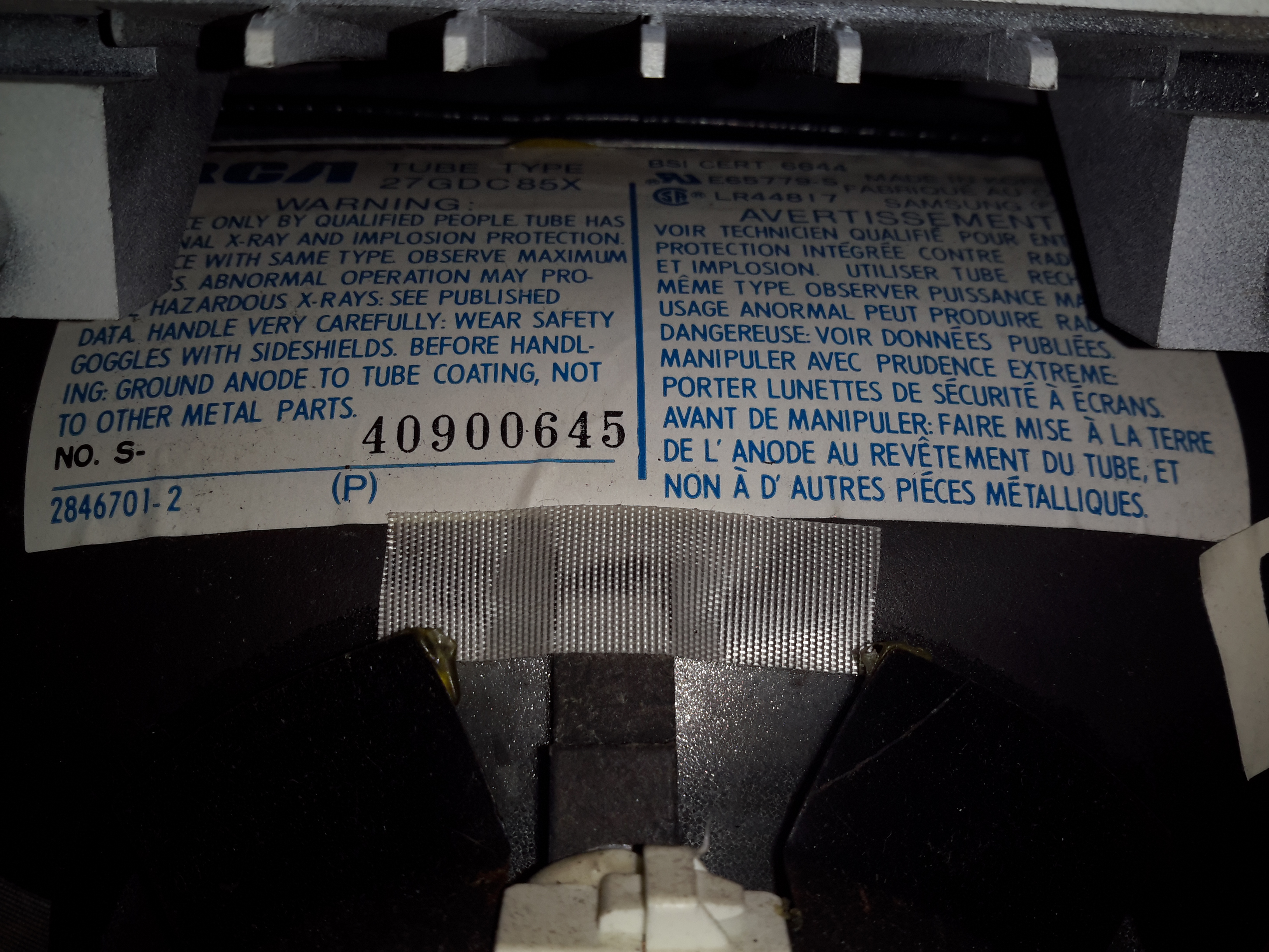
RCA 27GDC85X CRT
The colour CRT used is an RCA branded one, 27GDC85X.
Power Inputs
Like the other TV, this one is dual voltage input, mains 240v & 12v battery. This TV is a factory conversion of a standard 240v AC chassis though.
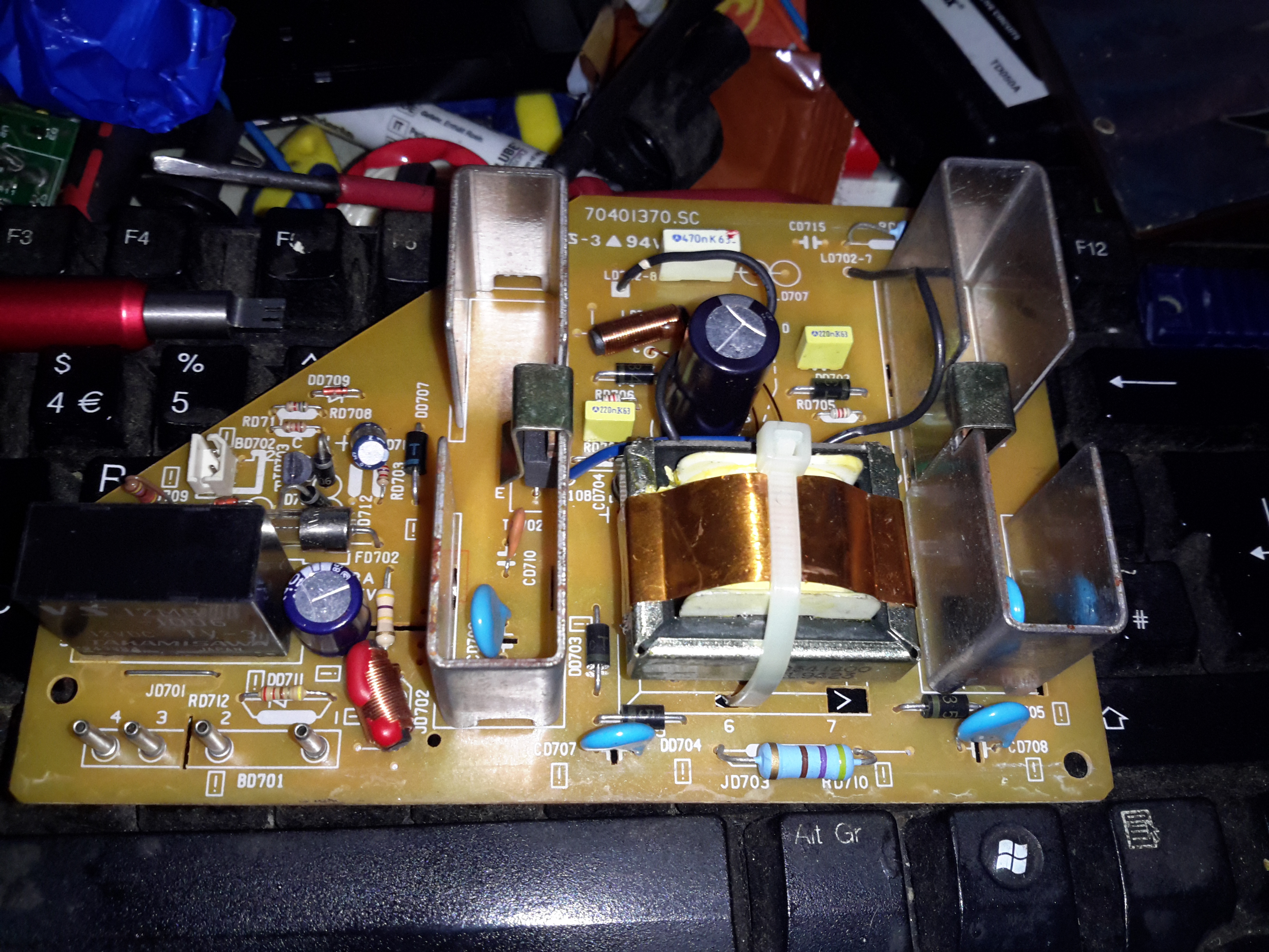
HV PSU
The 12v power first goes into this board, which looked suspiciously like an inverter. Measuring on the output pins confirmed I was right, this addon board generates a 330v DC supply under a load, but it’s not regulated at all, under no load the output voltage shoots up to nearly 600v!
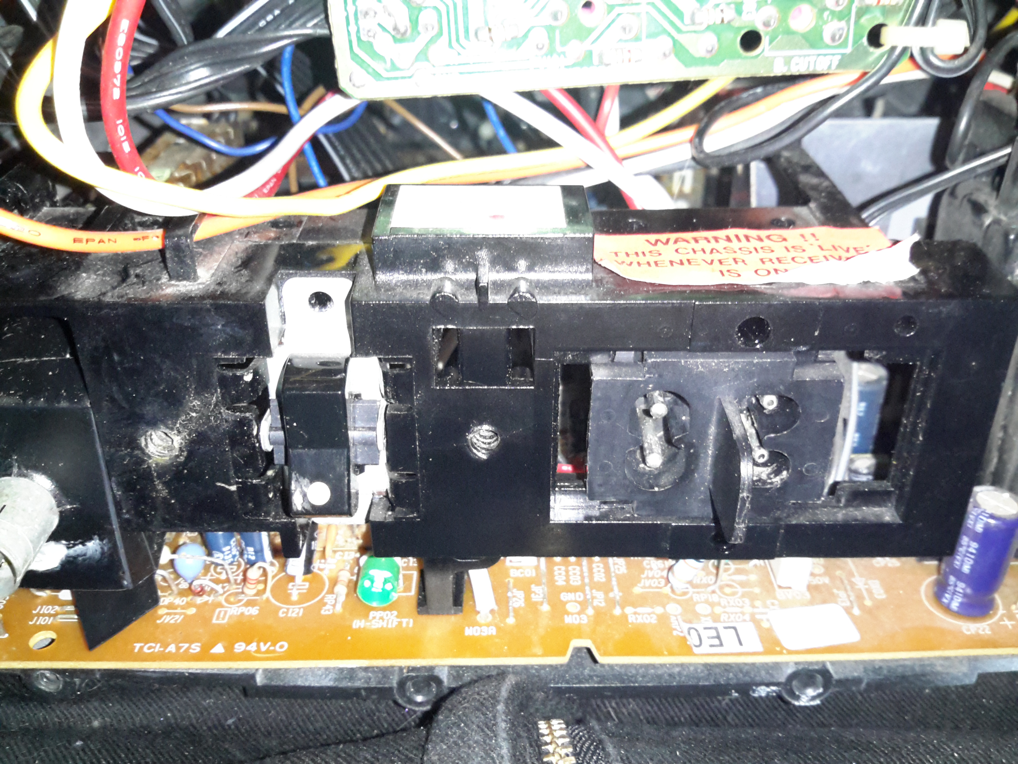
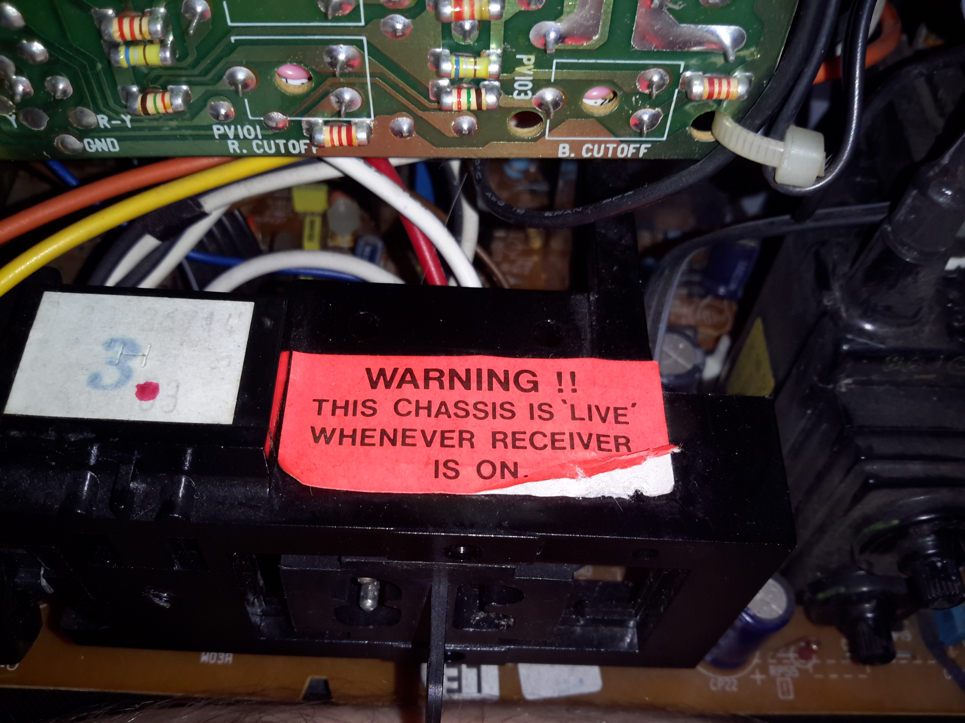
Live Chassis
I’ve not seen one of these labels on a TV for many years, when back in the very old TV sets the steel chassis would be used to supply power to parts of the circuitry, to save on copper. Although it doesn’t have a metal chassis to actually become live, so I’m not sure why it’s here.
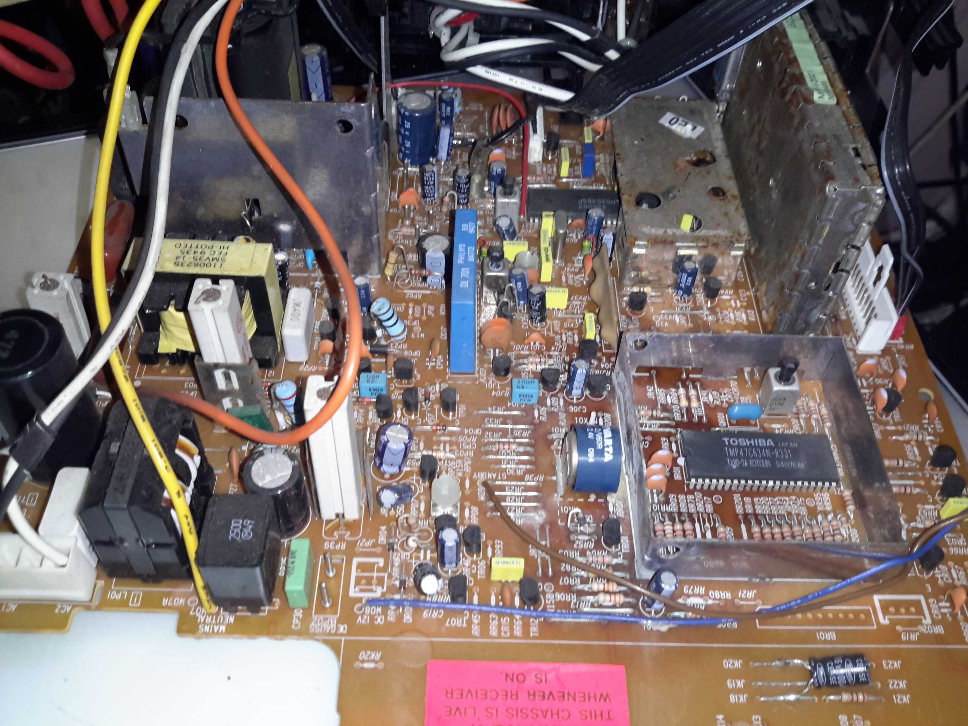
Main PCB
The main PCB is much more integrated in this newer TV, from the mid 90’s, everything is pretty much taken care of by silicon by this point.
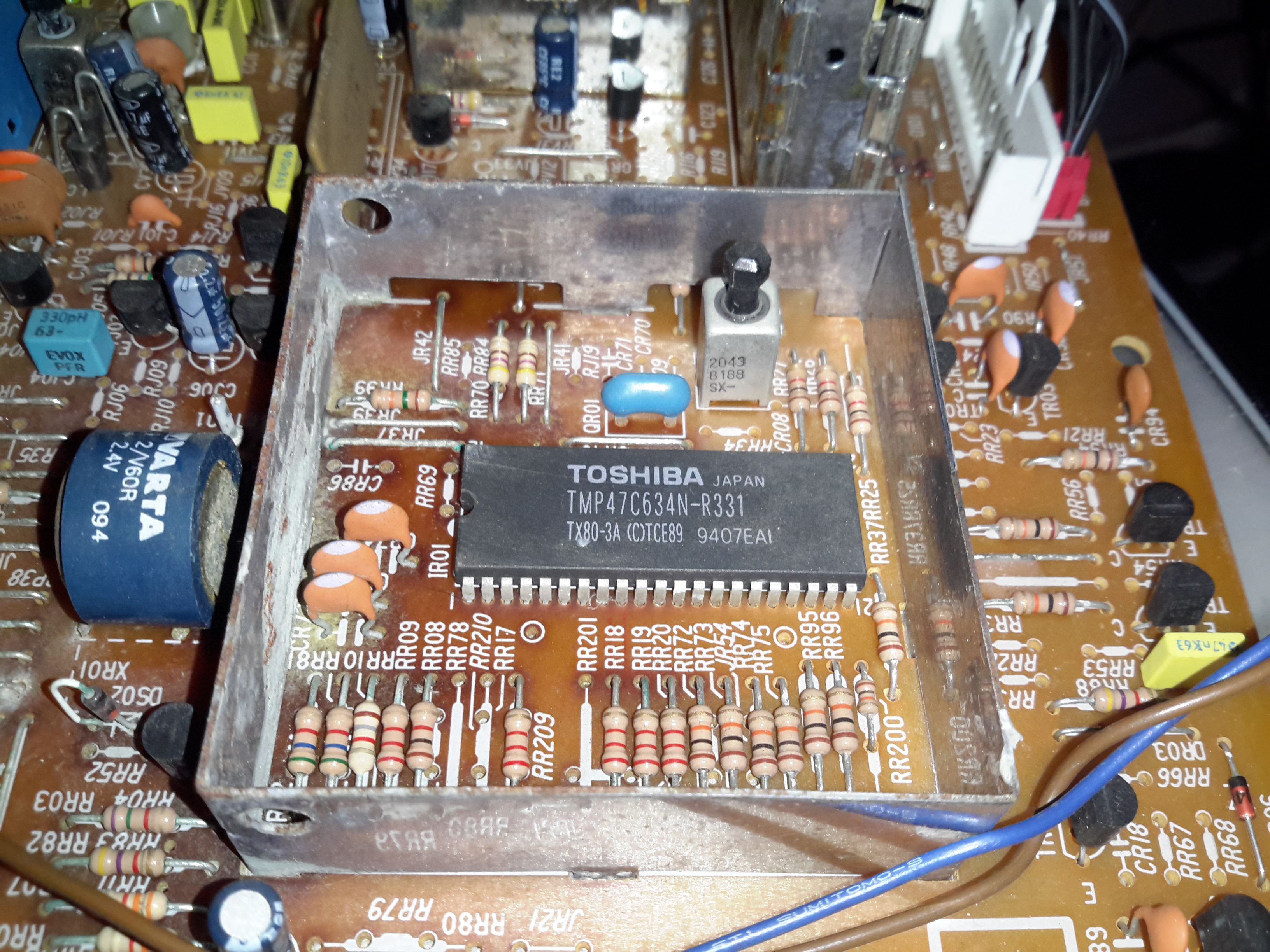
Main Microcontroller
This Toshiba µC takes care of channel switching & displaying information on the CRT. The tuner in this TV is electronically controlled.
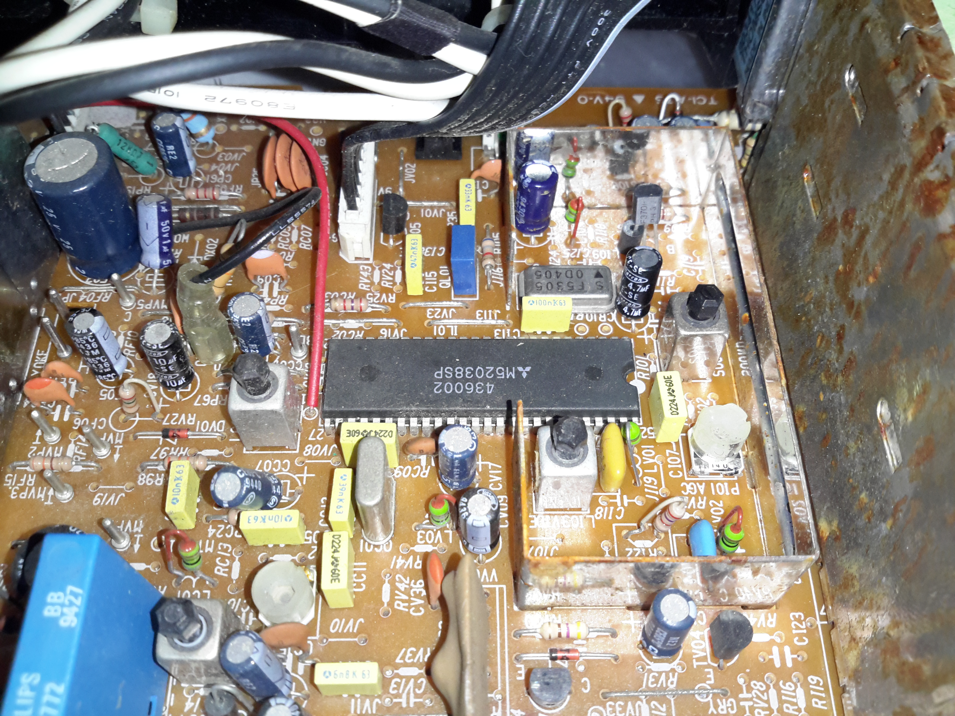
PAL Signal Processor
The video signal is handled by this Mitsubishi IC, which is a PAL Signal Processor, this does Video IF, Audio IF, Chroma, & generates the deflection oscillators & waveforms to drive the yoke.
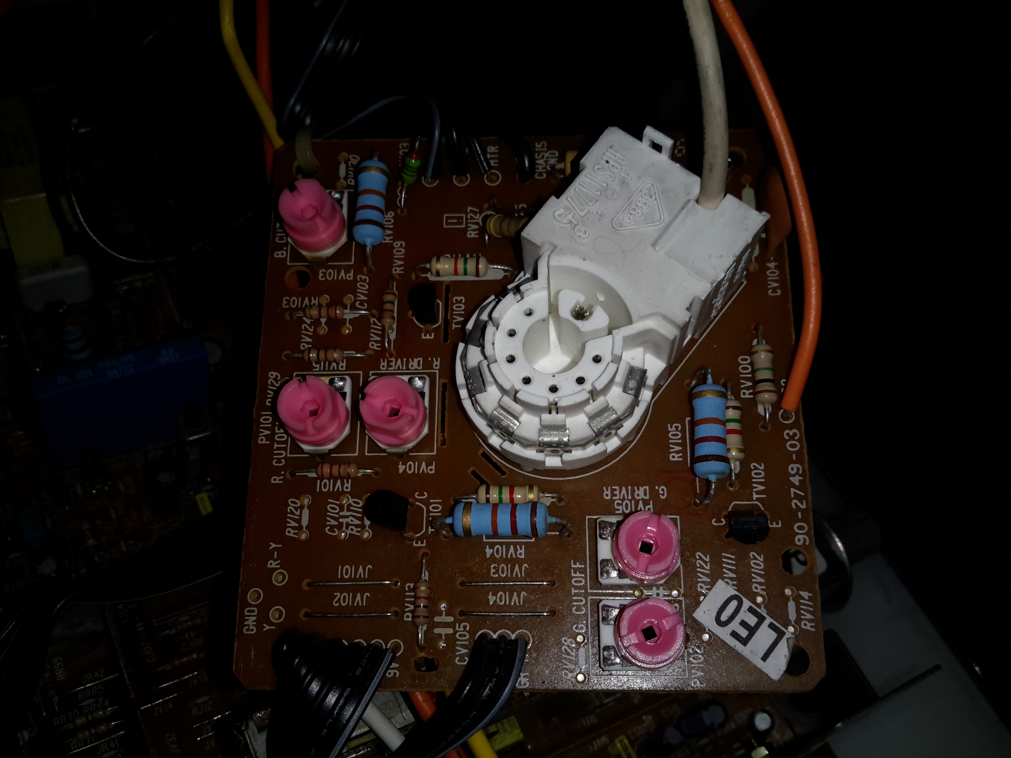
CRT Adjustments
There are some adjustments on the CRT neck board for RGB drive levels & cutoff levels. This board also had the final video amplifiers onboard, which drive the CRT cathodes.
The other day at the local canal-side waterpoint, this TV was dumped for recycling, along with another later model Colour TV. This is a 1970’s Black & White mains/battery portable made by Thorn. It’s based on a common British Radio Corporation 1590 chassis. Having received a soaking from rain, I didn’t expect this one to work very well.
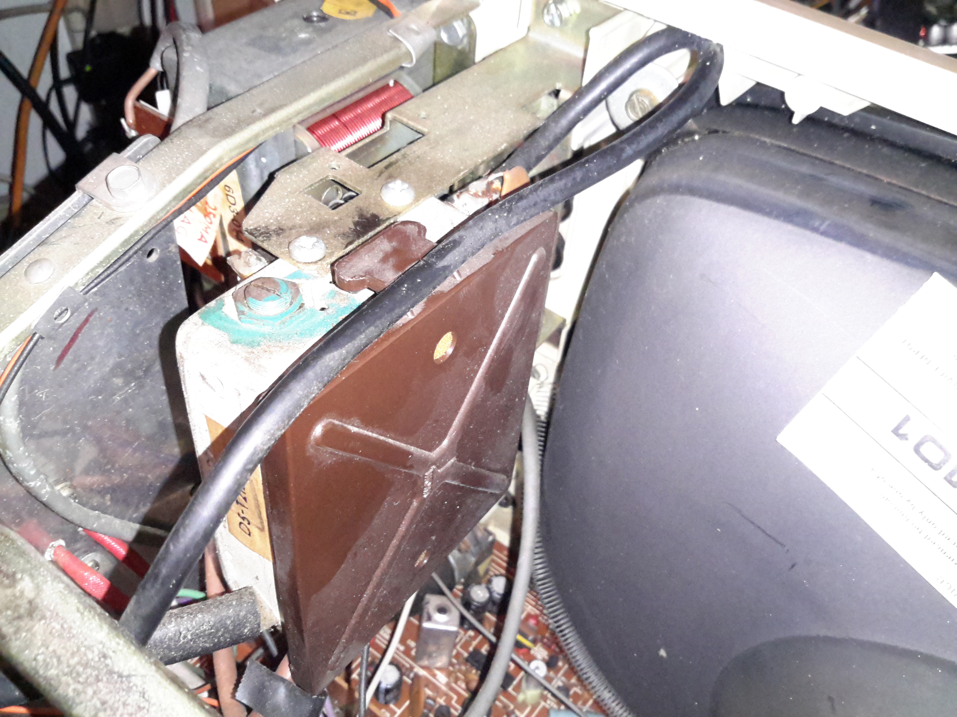
Tuner
Being so old, there is no electronic control of the tuner in this TV, and only has the capability to mechanically store 4 different channels. The tuner itself is a cast box with a plastic cover.
Tuning Lever
The mechanical buttons on the front of the TV push on this steel bar, by different amounts depending on the channel setting. This bar is connected to the tuning capacitor inside the tuner.
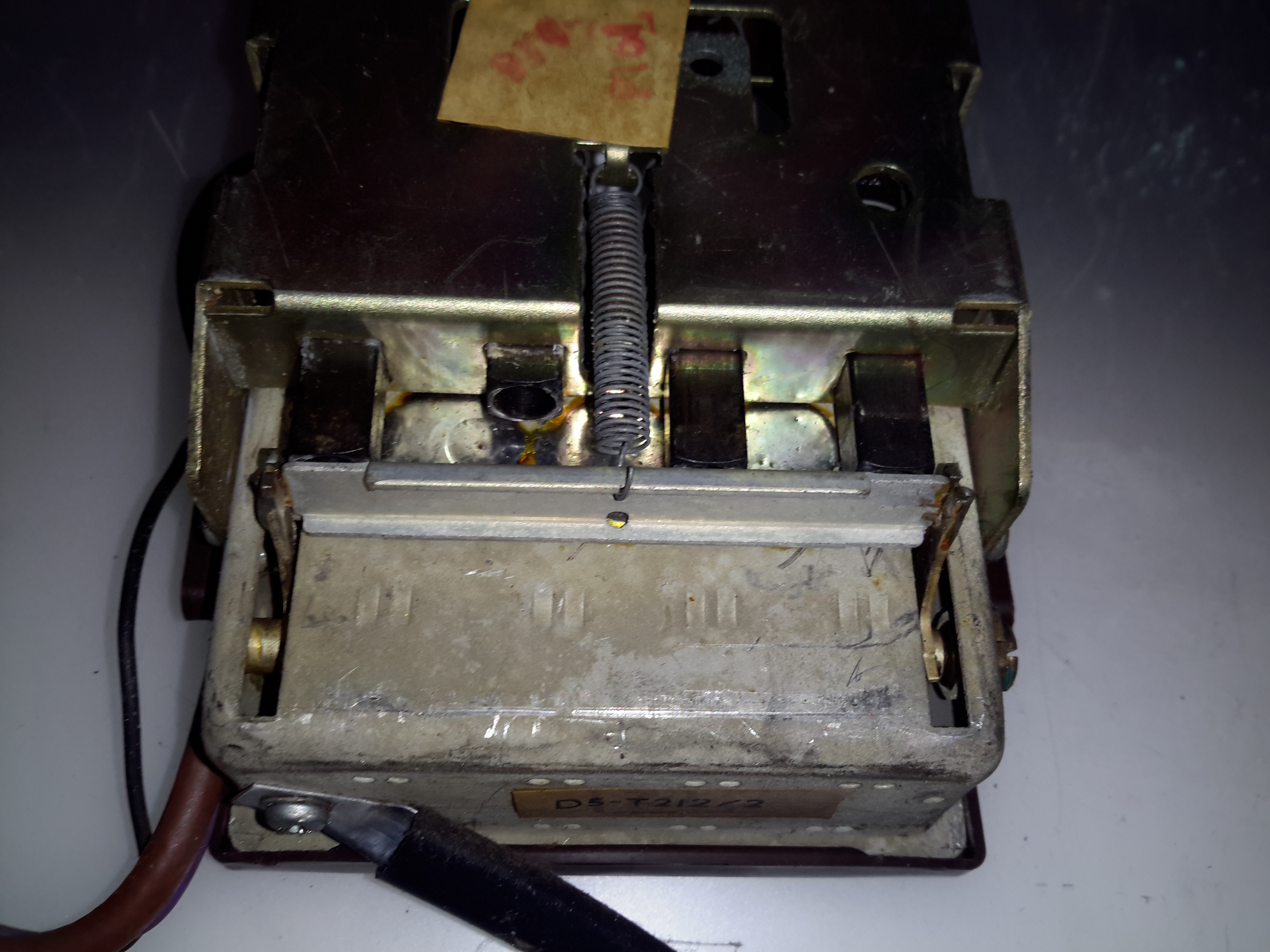
Tuner Compartments
Unclipping the plastic cover, with it’s lining of aluminium foil for shielding reveals the innards of the tuner module.
Tuner Input Stage
Here’s the tuner front end RF transistor, which has it’s can soldered into the frame, this is an AF239 germanium UHF transistor, rated at up to 900MHz.
Tuner IF Mixer Stage
As the signal propagates through the compartments of the tuner, another transistor does the oscillator / IF mixing, an AF139 germanium, rated to 860MHz.
Tuning Capacitor
As the buttons on the front of the set are pushed, moving the lever on the outside, the tuning capacitor plates intermesh, changing the frequency that is filtered through the tuner. The outer blades of the moving plates are slotted to allow for fine tuning of the capacitance, and therefore transmitted frequency by bending them slightly.
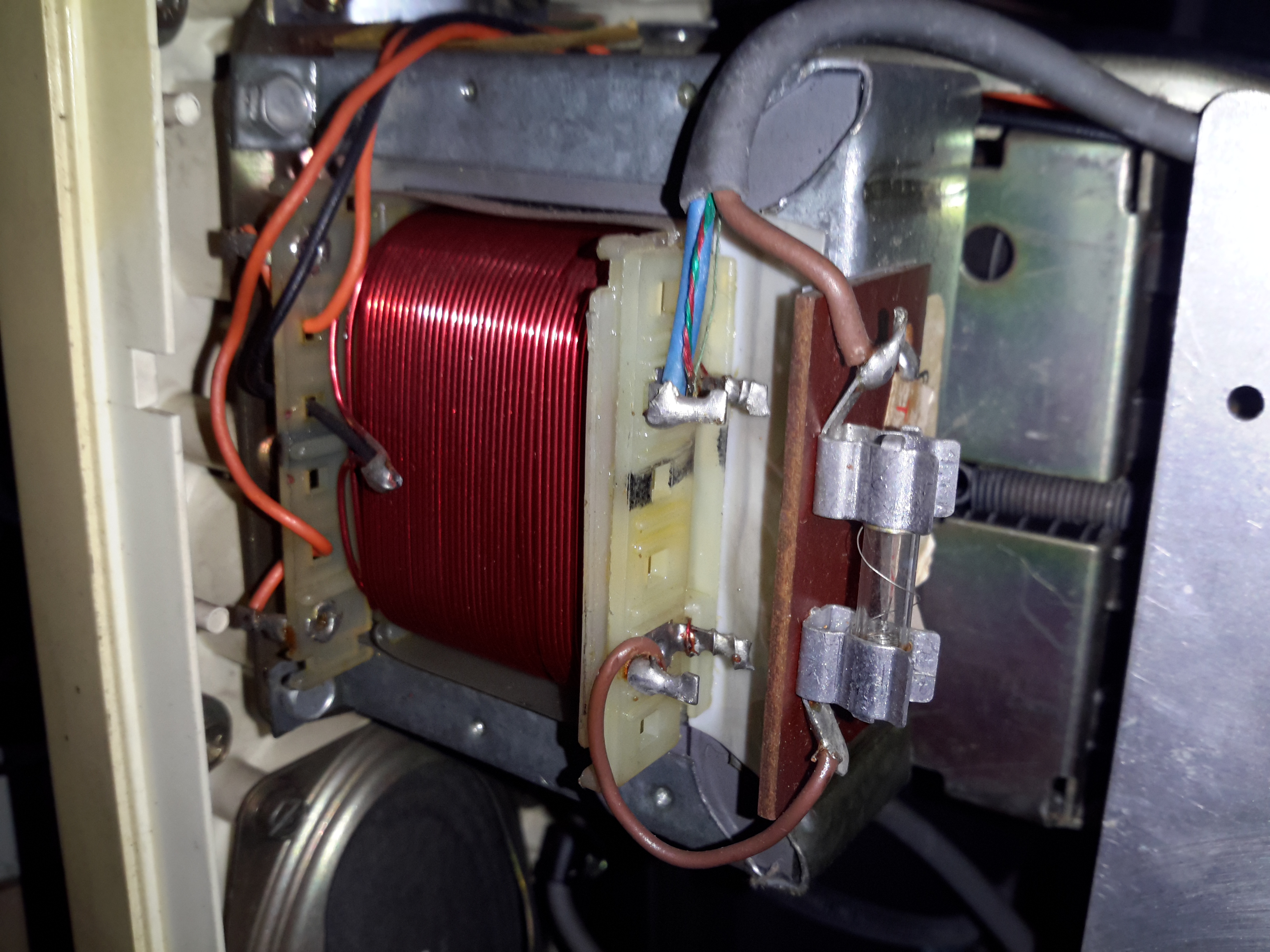
Mains Transformer
Being a dual supply TV that can operate on either 12v battery power or mains, this one has a large centre tapped mains transformer that generates the low voltage when on AC power. Full wave rectification is on the main PCB. The fuse of this transformer has clearly been blown in the past, as it’s been wound with a fine fuse wire around the outside to repair, instead of just replacing the fuse itself.
Chassis Rear
The back of the set has all the picture controls on the bottom edge, with the power input & antenna connections on the left just out of shot. The CRT in this model is an A31-120W 12″ tube, with a really wide deflection angle of 110°, which allows the TV to be smaller.
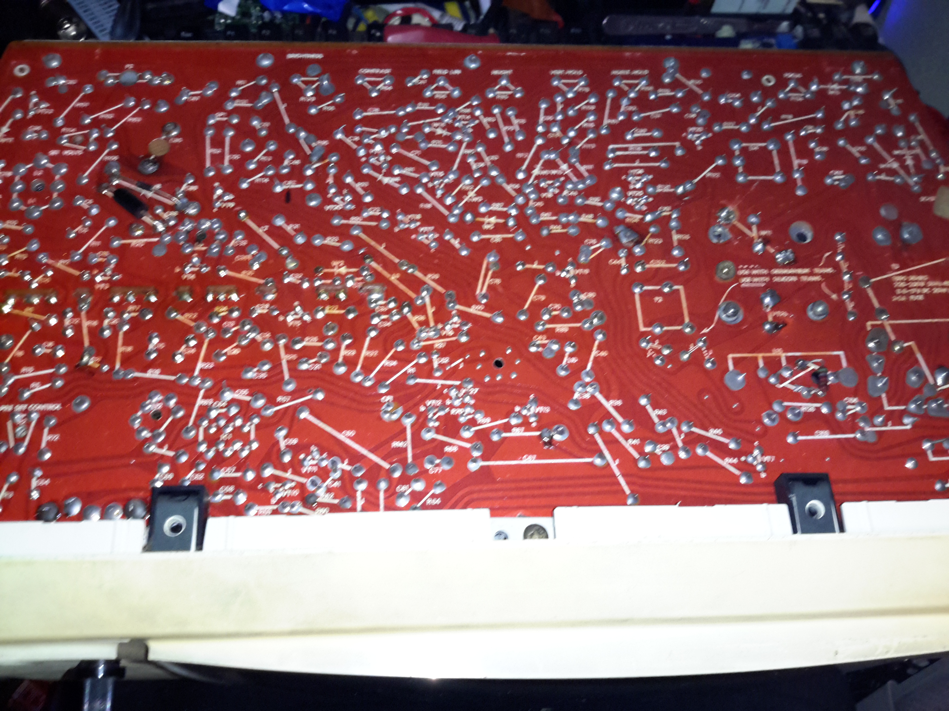
Main PCB
The bottom of the mainboard has all the silkscreen markings for the components above which certainly makes servicing easier 😉 This board’s copper tracks would have been laid out with tape, obviously before the era of PCB design software.
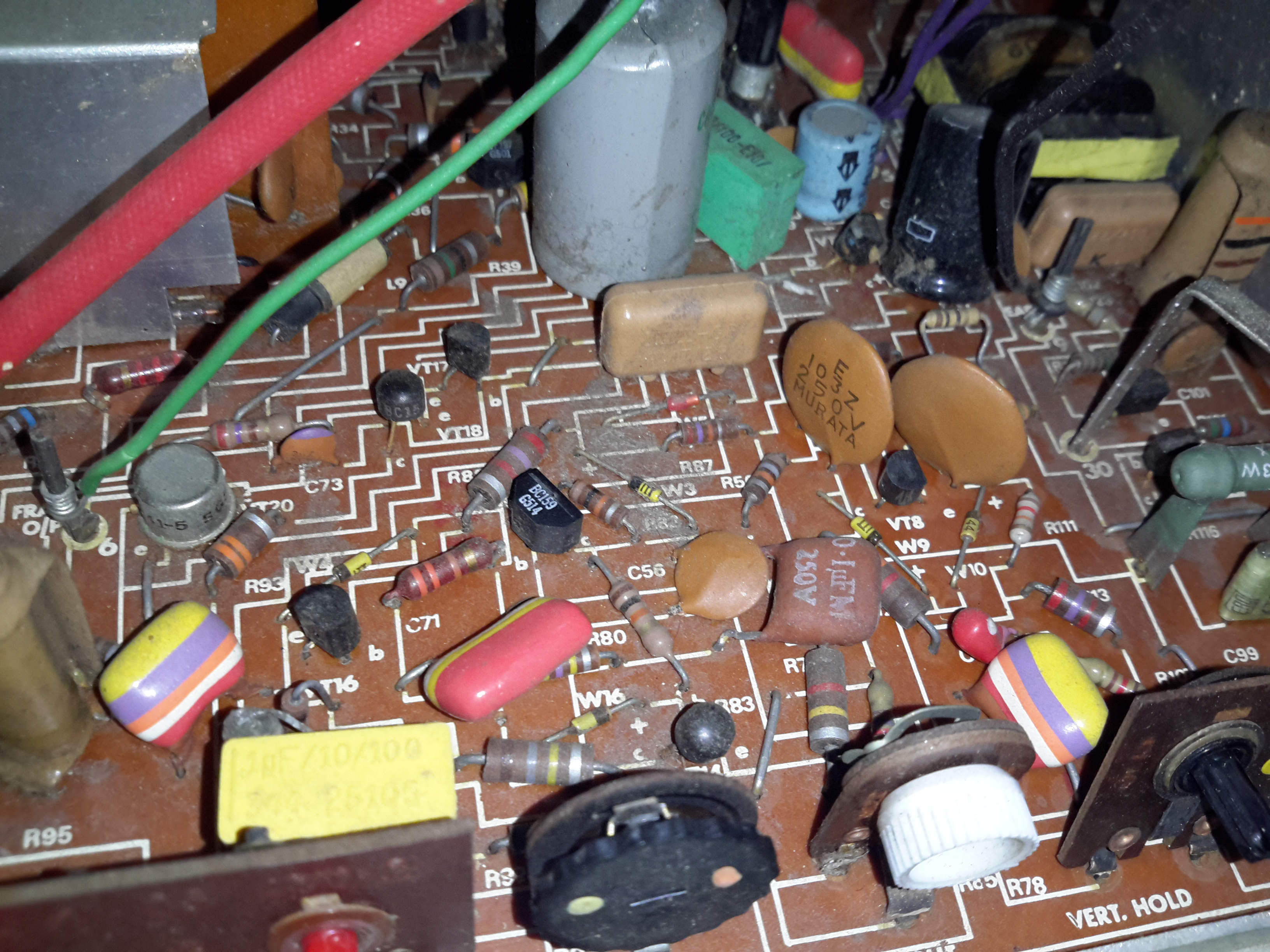
Components
The components on this board are laid out everywhere, not just in square grids. The resistors used are the carbon composition type, and at ~46 years old, they’re starting to drift a bit. After measuring a 10K resistor at 10.7K, all of these would need replacing I have no doubt. Incedentally, this TV could be converted to take a video input without the tuner, by lifting the ferrite beaded end of L9 & injecting a signal there.
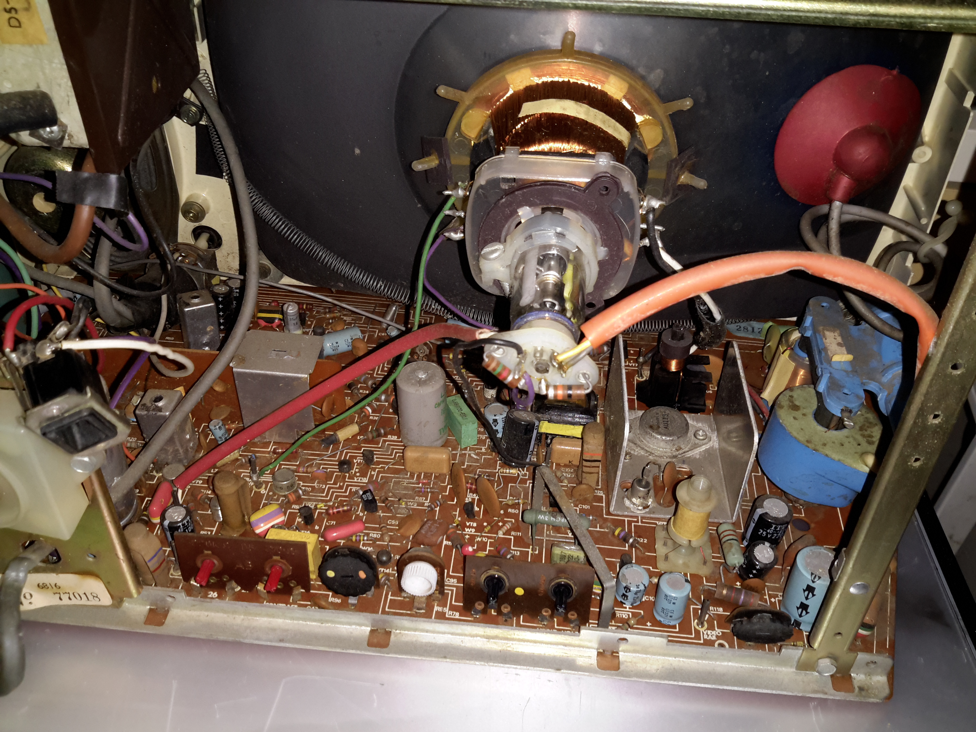
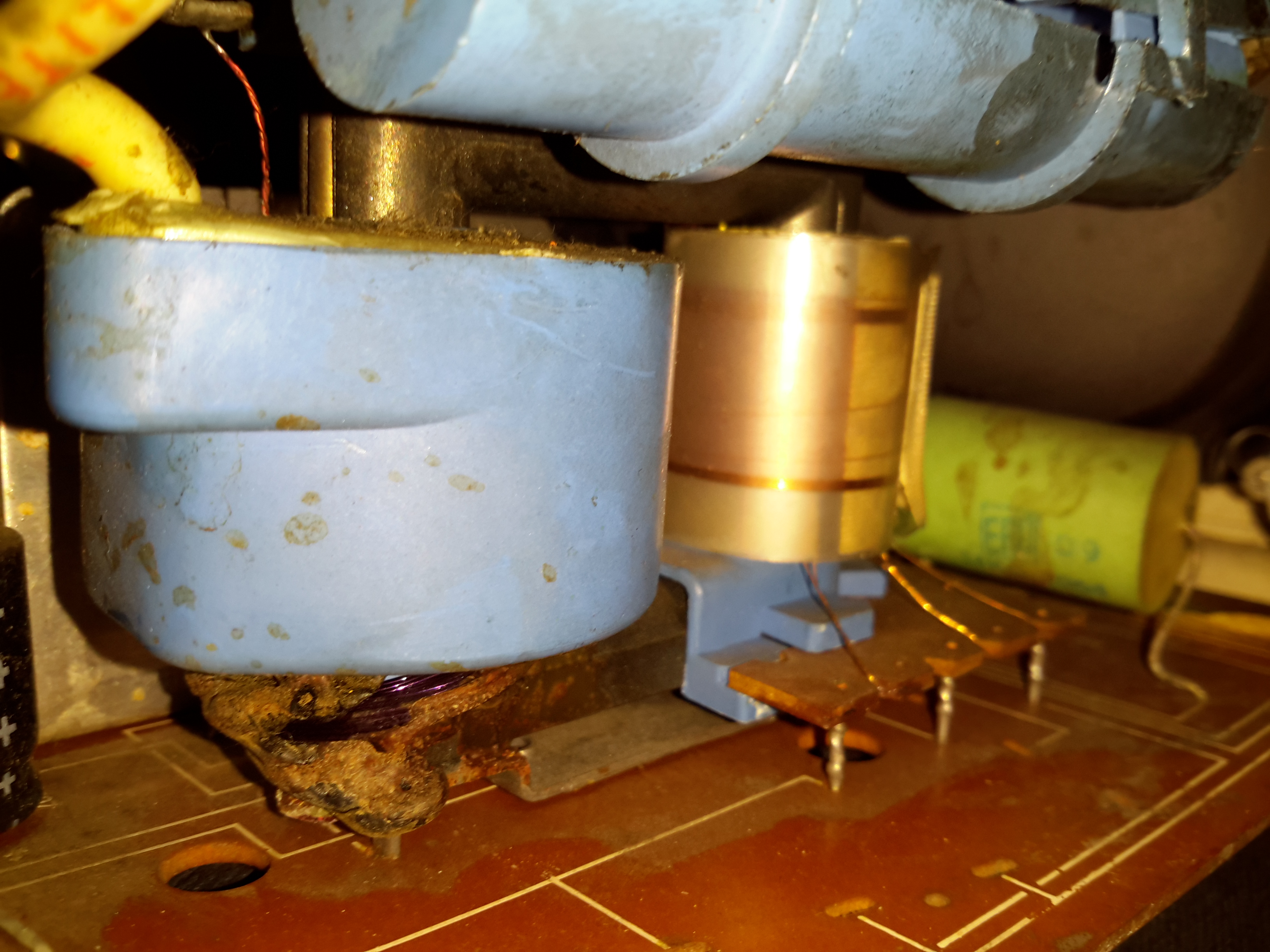
Flyback Primary Windings
The flyback (Line Output Transformer) is of the old AC type, with the rectifier stack on top in the blue tube, as opposed to more modern versions that have everything potted into the same casing. The primary windings are on the other leg of the ferrite core, making these transformers much more easily repairable. This transformer generates the 12kV required for the CRT final anode, along with a few other voltages used in the TV, for focussing, etc.
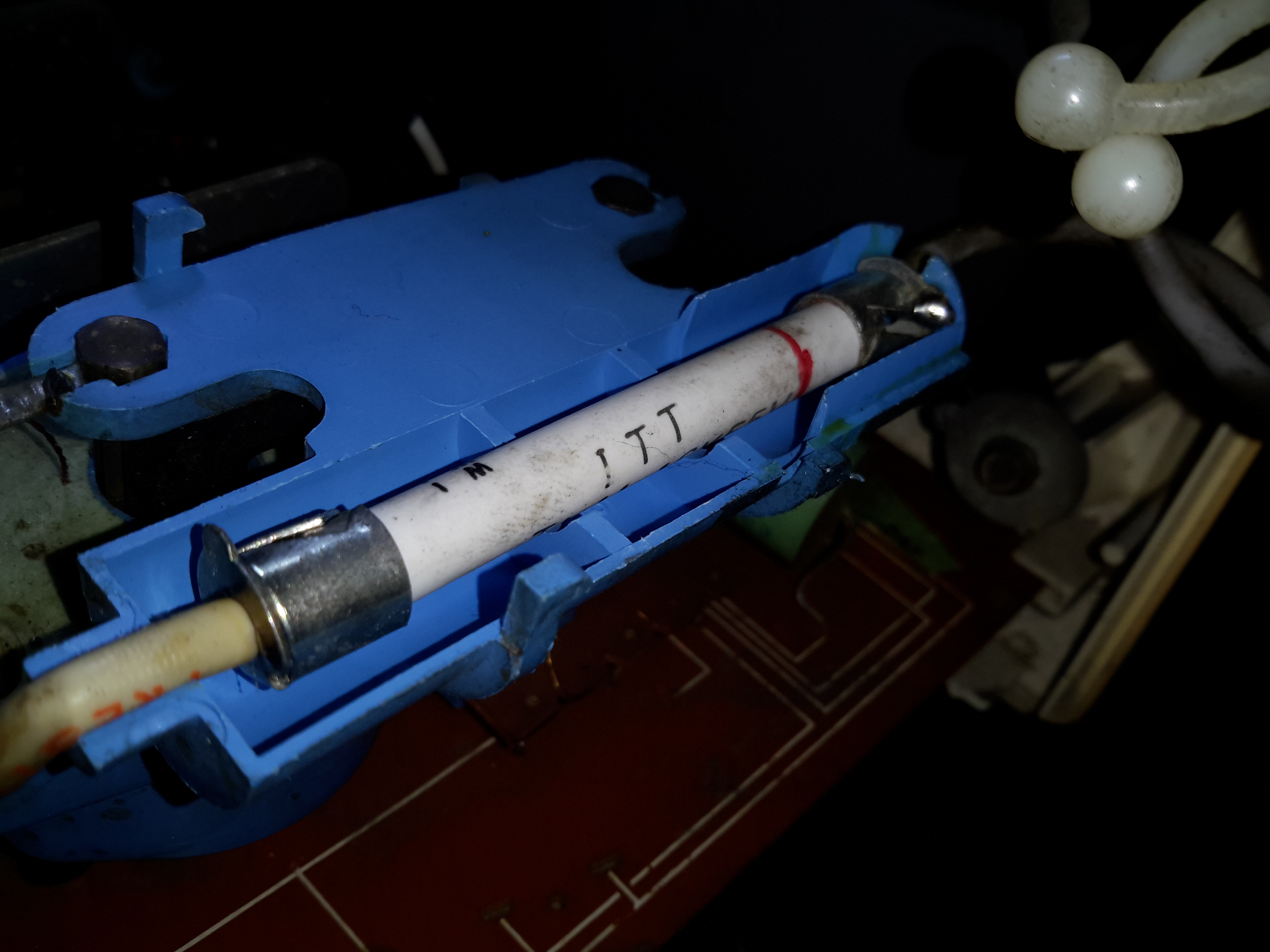
Rectifier Stack
The main EHT rectifier stack looks like a huge fuse, inside the ceramic tube will be a stack of silicon diodes in series, to withstand the high voltage present.
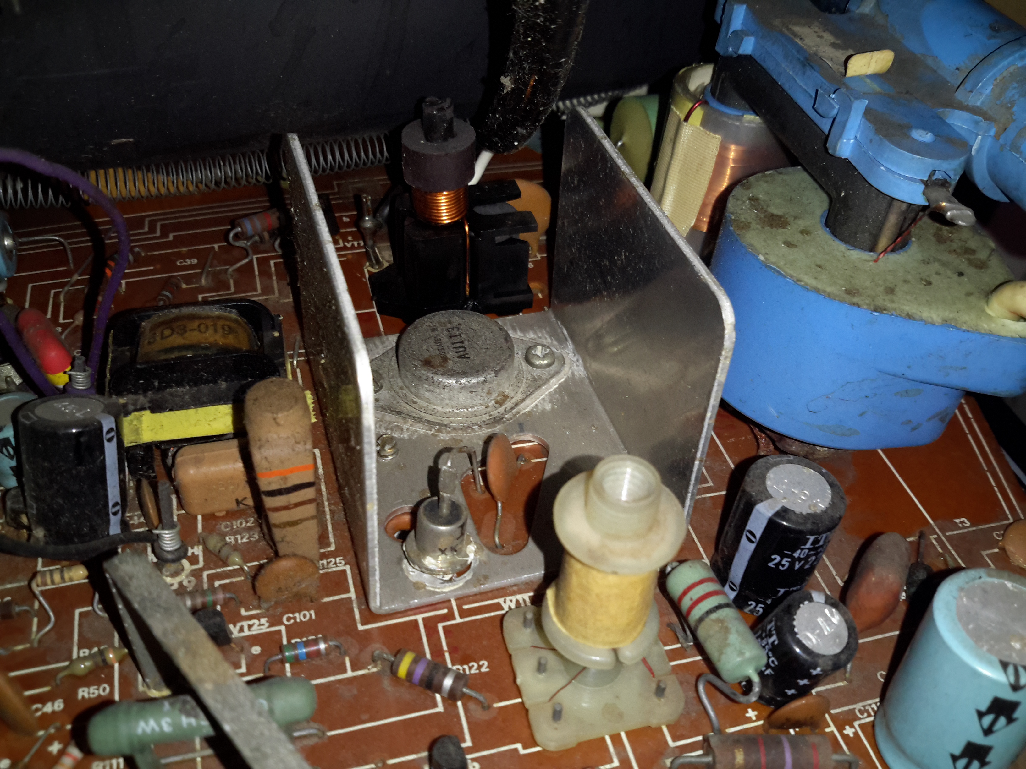
Horizontal Output Transistor
This is the main switching transistor that drives the flyback, the HOT. This is an AU113, another germanium type, rated at 250v 4A. The large diode next to the transistor is the damper.
I’ve managed to find all the service information for this set online, link below!
[download id=”5616″]
More to come if I manage to get this TV working!
Tip Jar
If you’ve found my content useful, please consider leaving a donation by clicking the Tip Jar below!
All collected funds go towards new content & the costs of keeping the server online.