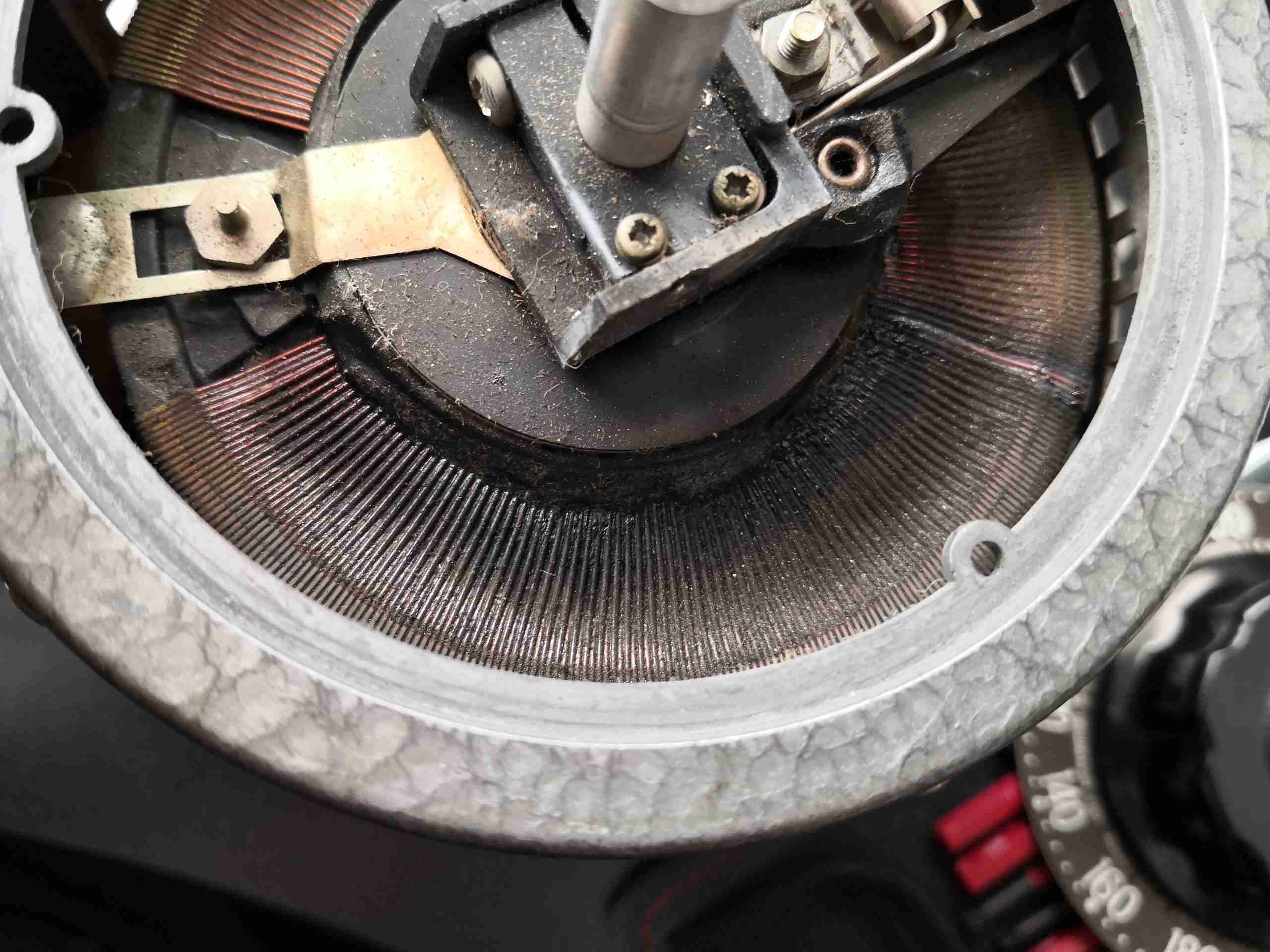
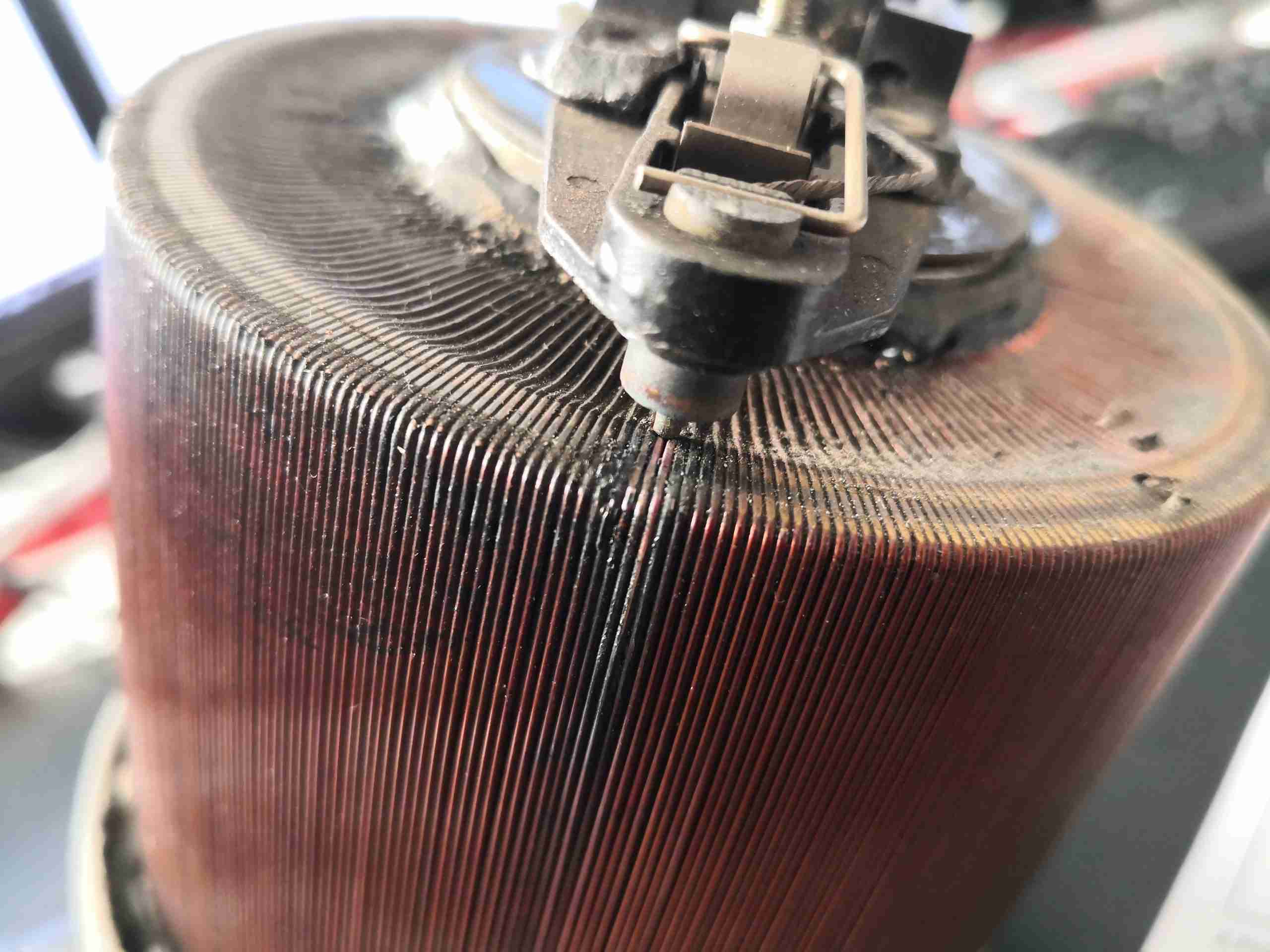
Well, this is what happens when a Variac rated at 3A is subjected to 15A for a while – a complete burnout. The smell associated with this failure was formidable, it’s a shame I can’t convey odour through photos! Above is the burned section of the winding (it was set for around 115v output from our 240v mains).
Top Cover Removed
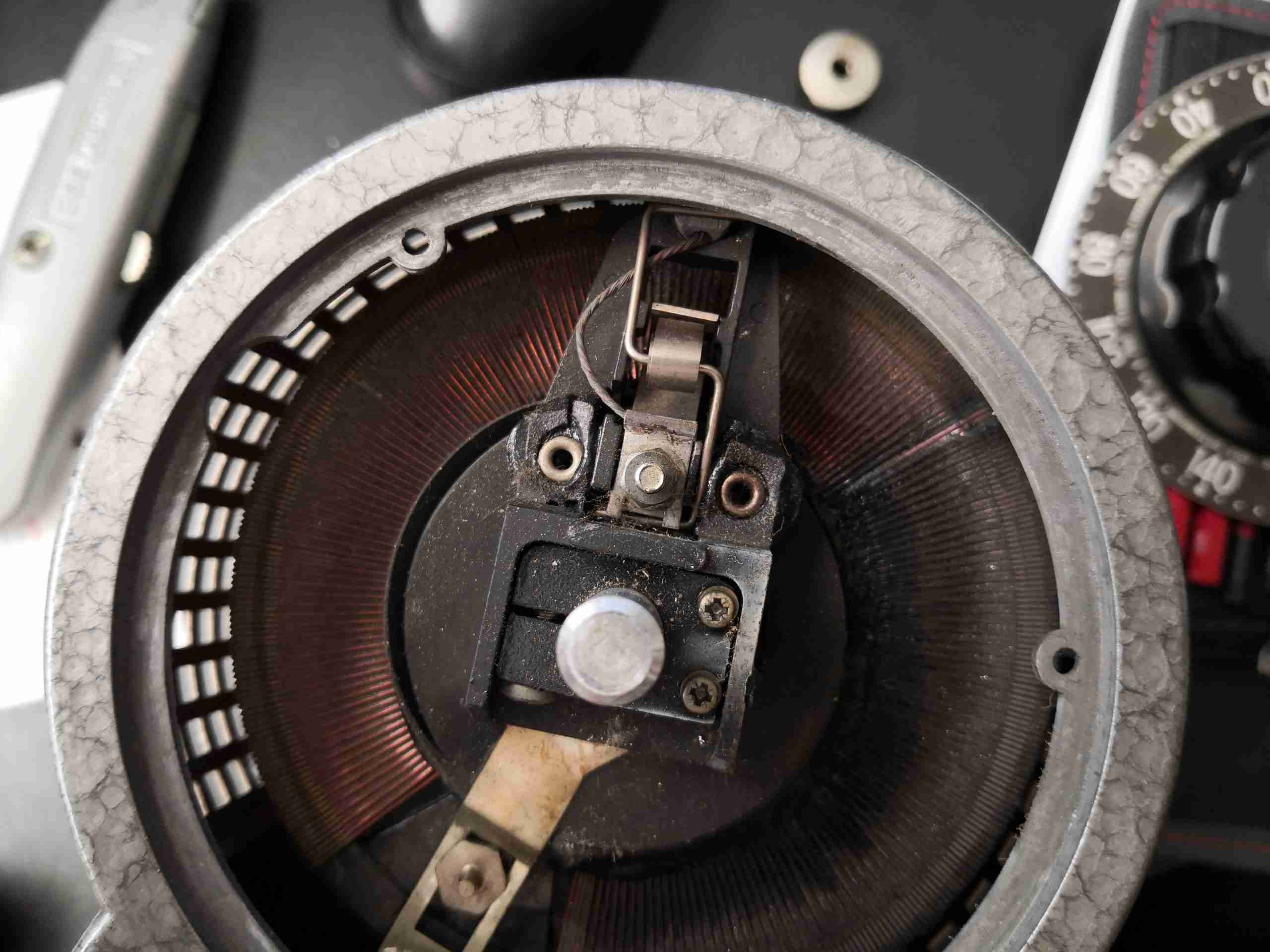
At first the rotor was stuck in position, but a bit of force allowed some movement. The armature holding the brush has melted at the rivets, and the copper tail from the brush is severely heat-discoloured. This got HOT! When brought to me just after failure, it was near impossible to hold onto the outer casing!
Smoke Residue
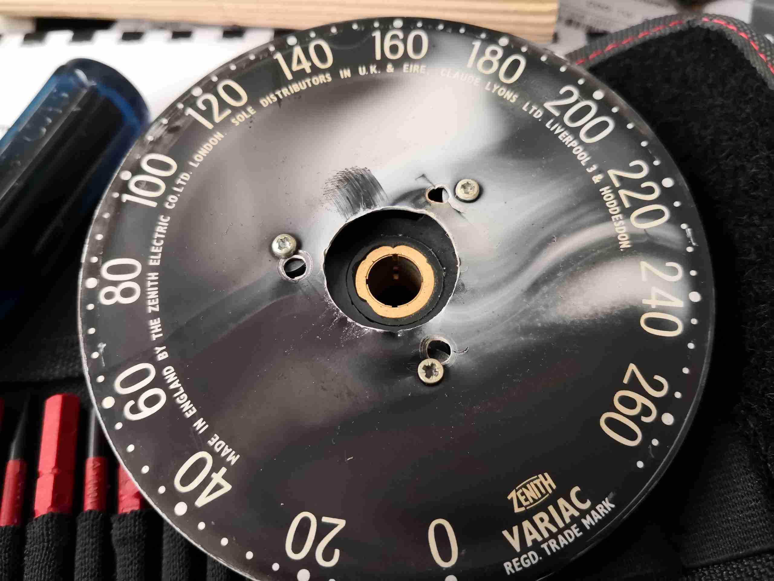
Underneath the control knob, there’s white ash, which has evolved from the insulation burning off the windings.
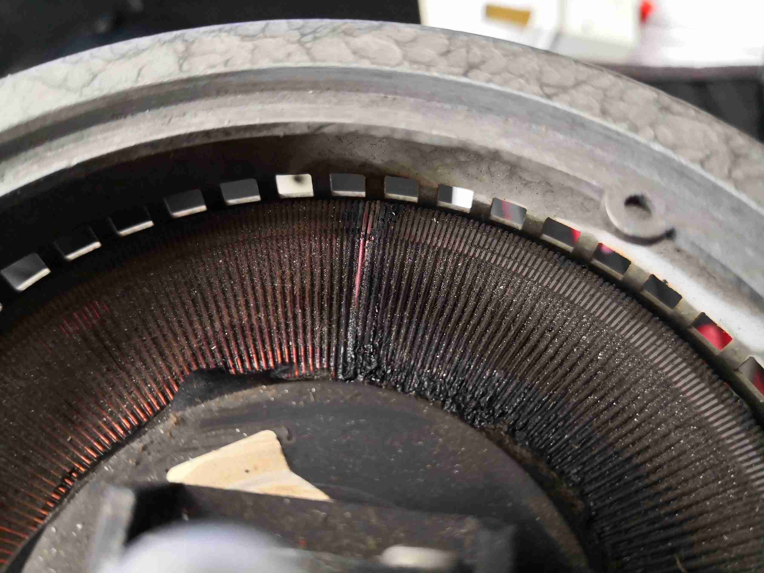
Shorted Turns
A closer look at the point where the brush was set shows the pair of windings have pretty much fused. The worst of the heating occurred here it seems.
Windings
The heating has extended down the windings and the insulation has melted all around the top & base of the toroid core. Unfortunately it’s the end of the line for this particular transformer, and it now rests in the Black Museum of Electrical Death.
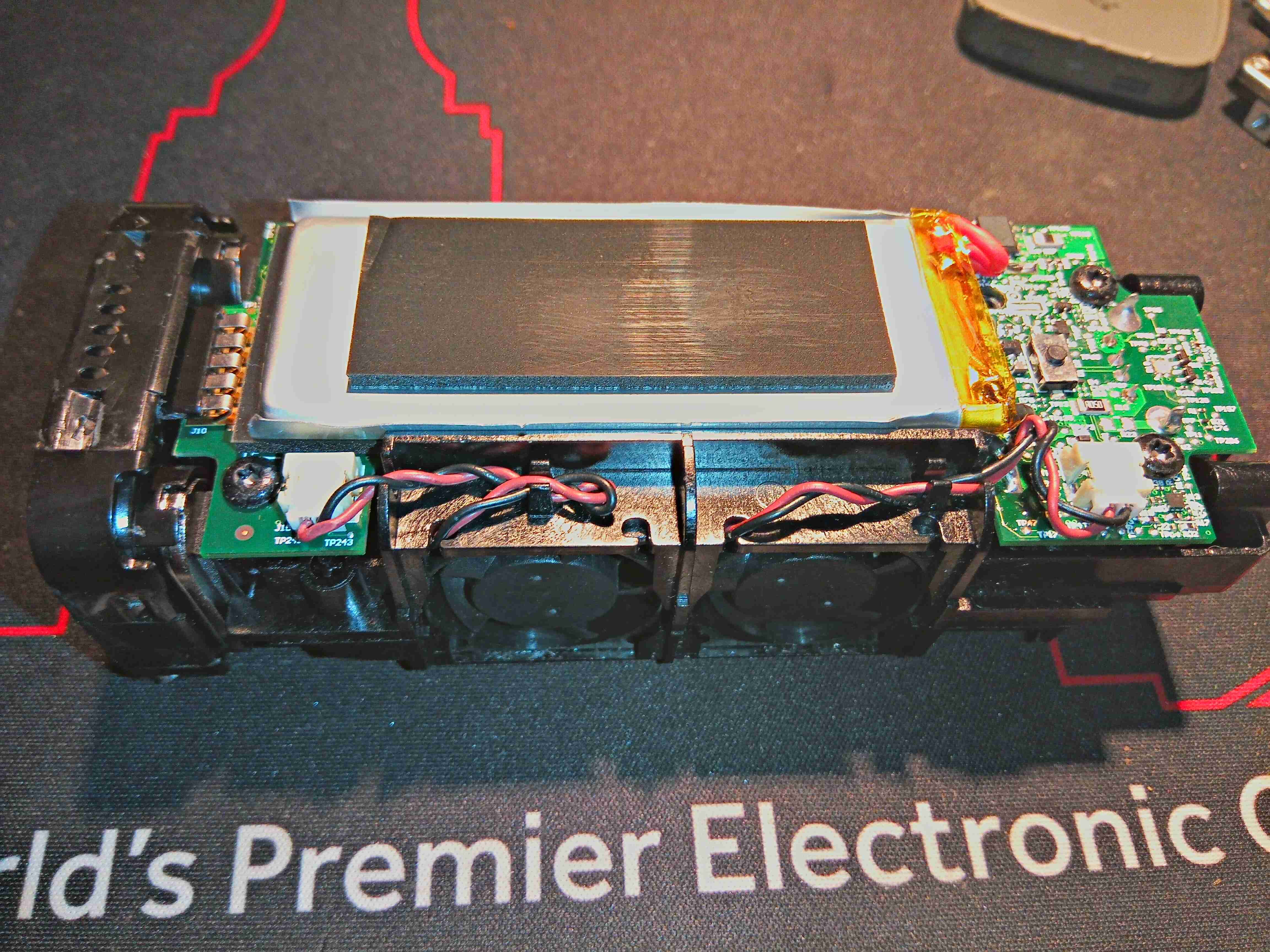
These projectors were very popular when they first appeared on the market with the laser hobbyist community, and for very good reason – they contain a massive array of 445nm Royal Blue laser diodes in their optics engine. Originally very expensive, these units can now be had for under £50 on eBay, usually with damaged DLP chips.
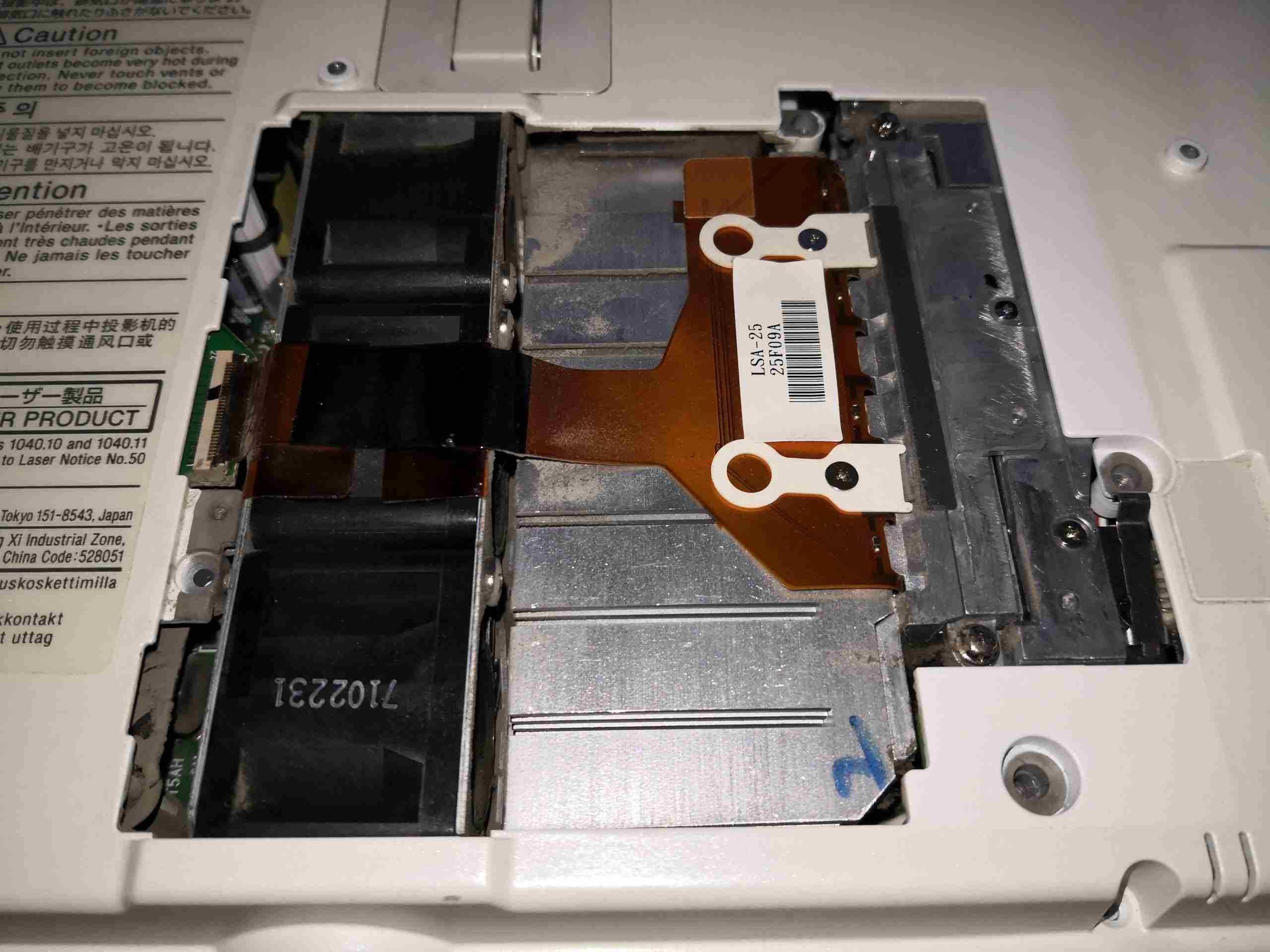
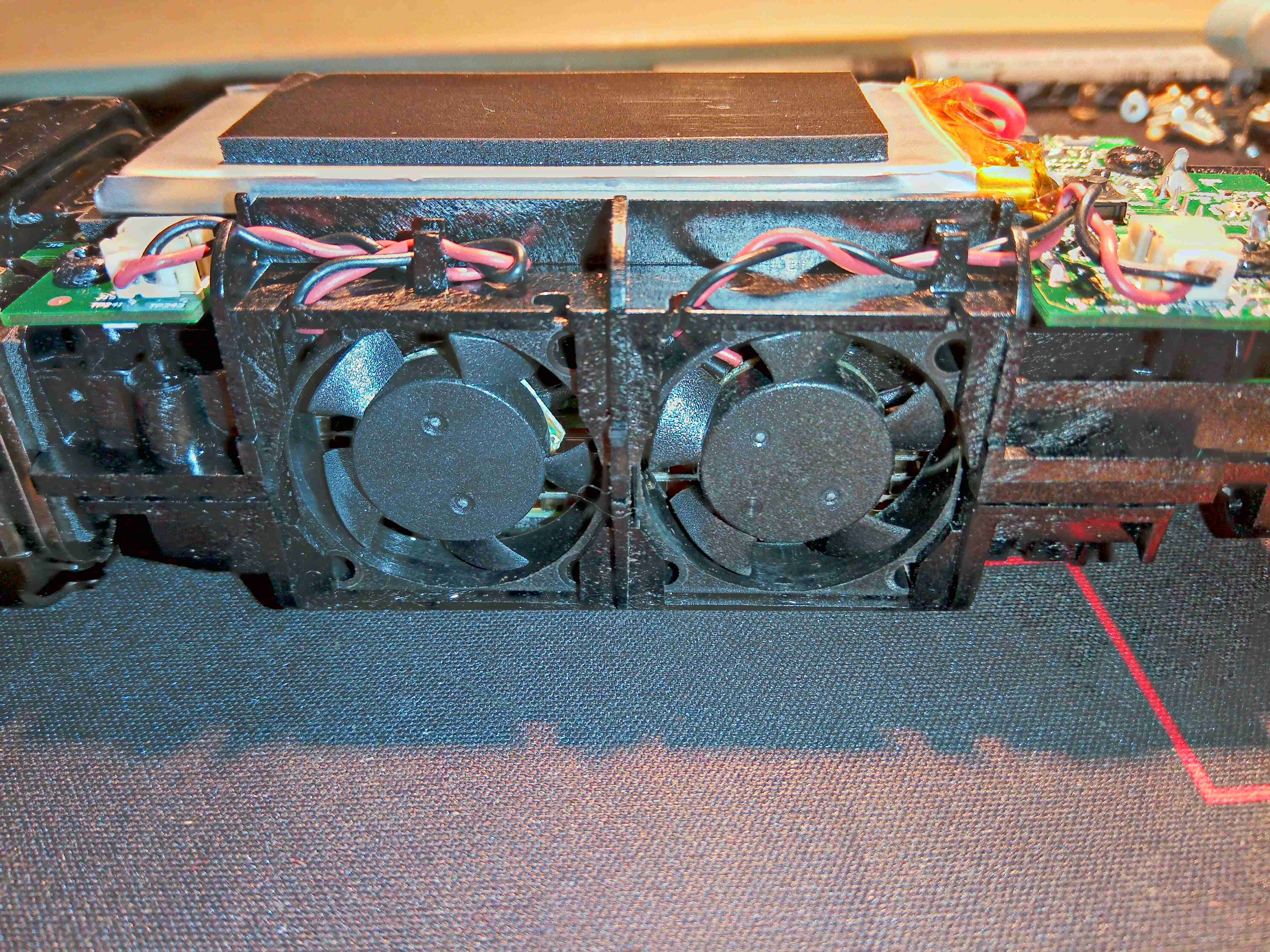
Laser Module Door
Under the door on the bottom of the projector is the 445nm Laser diode array module, itself secured in place with security screws to the beam combiner. The rack of 3 high speed fans to the left draws air over the substantial heatsink.
Top Cover Removed
After removing the shell securing screws, the top cover comes off with the button panel. This gives a view of the internals, mostly PCBs at this stage.
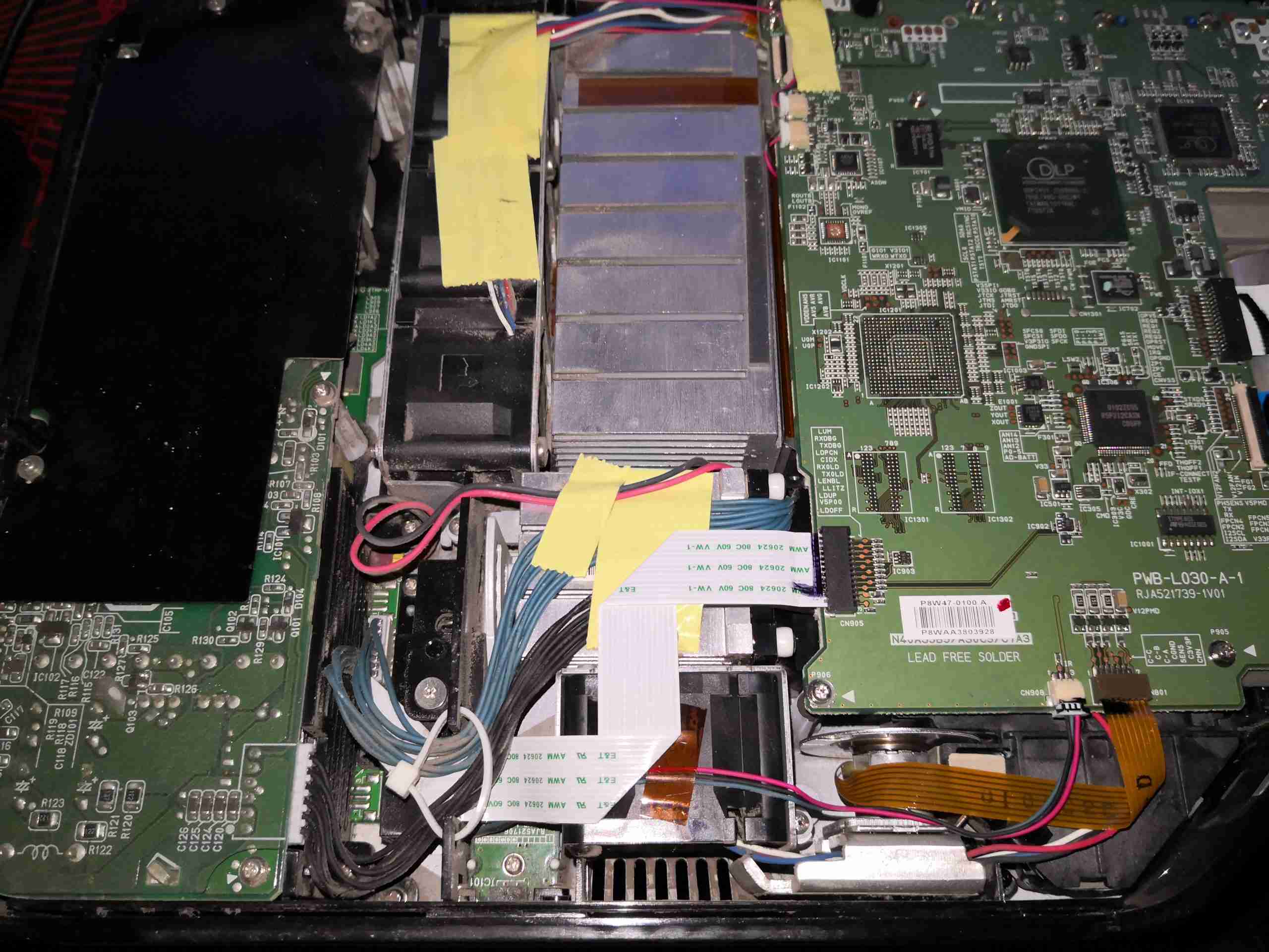
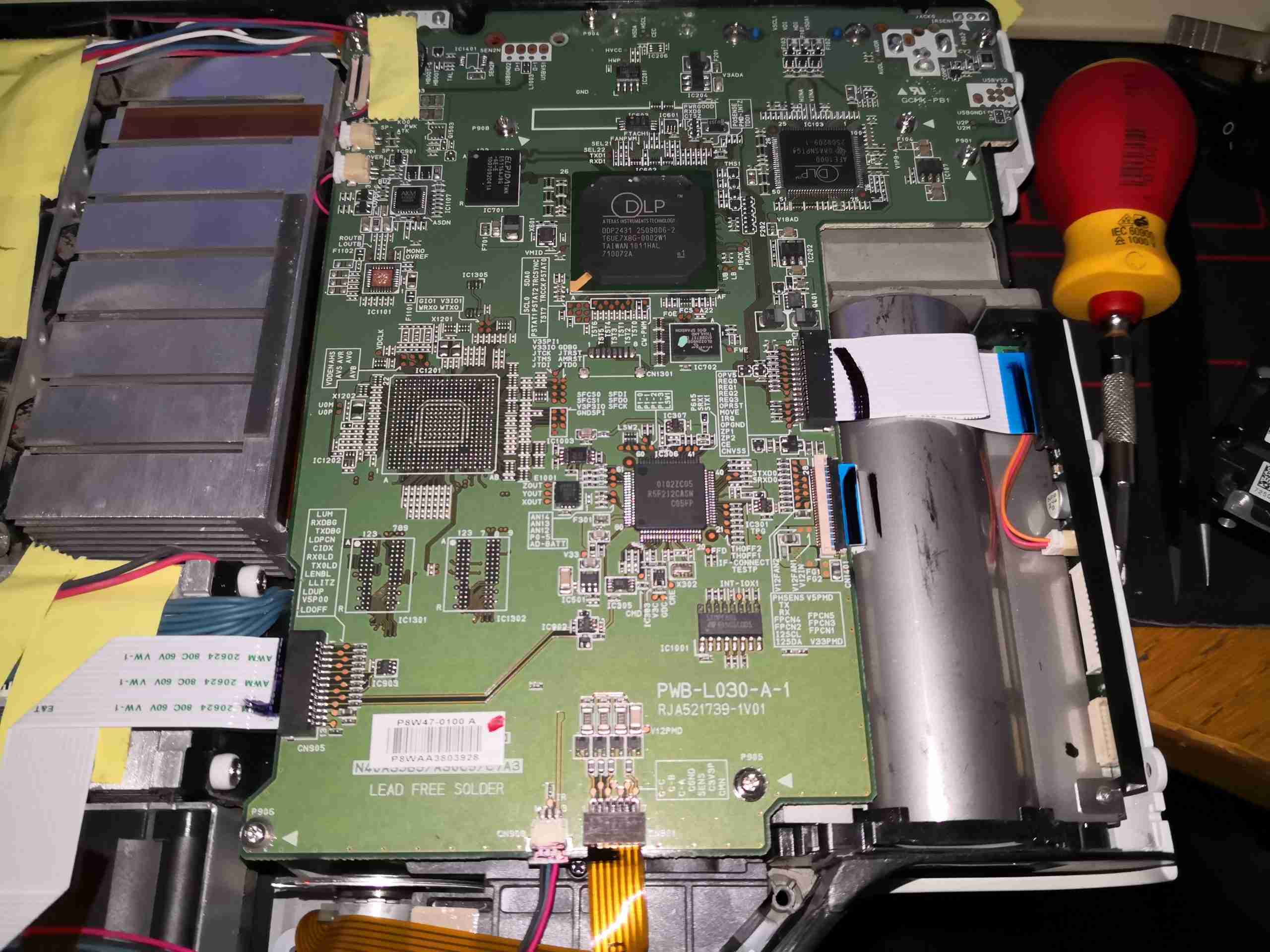
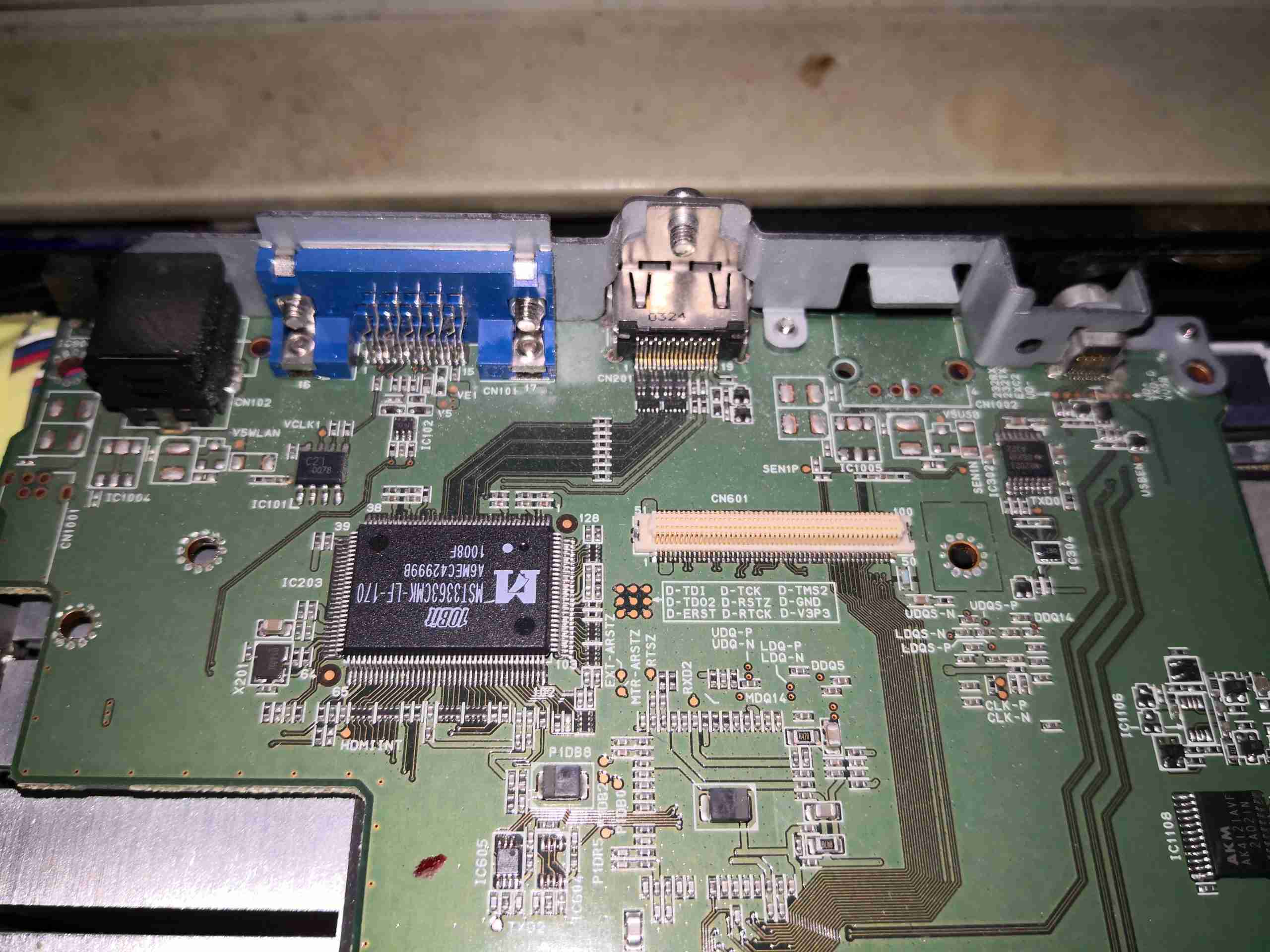
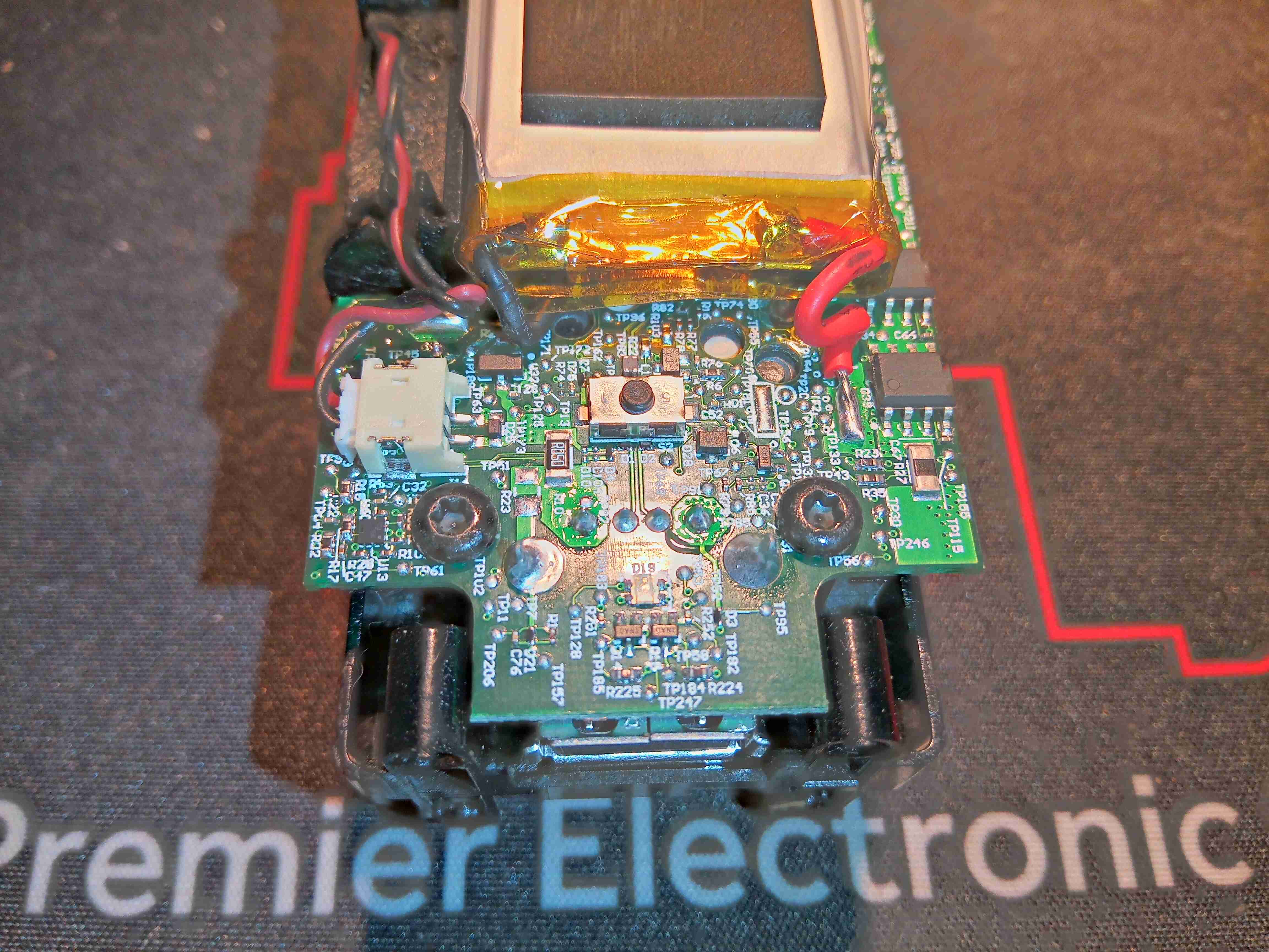
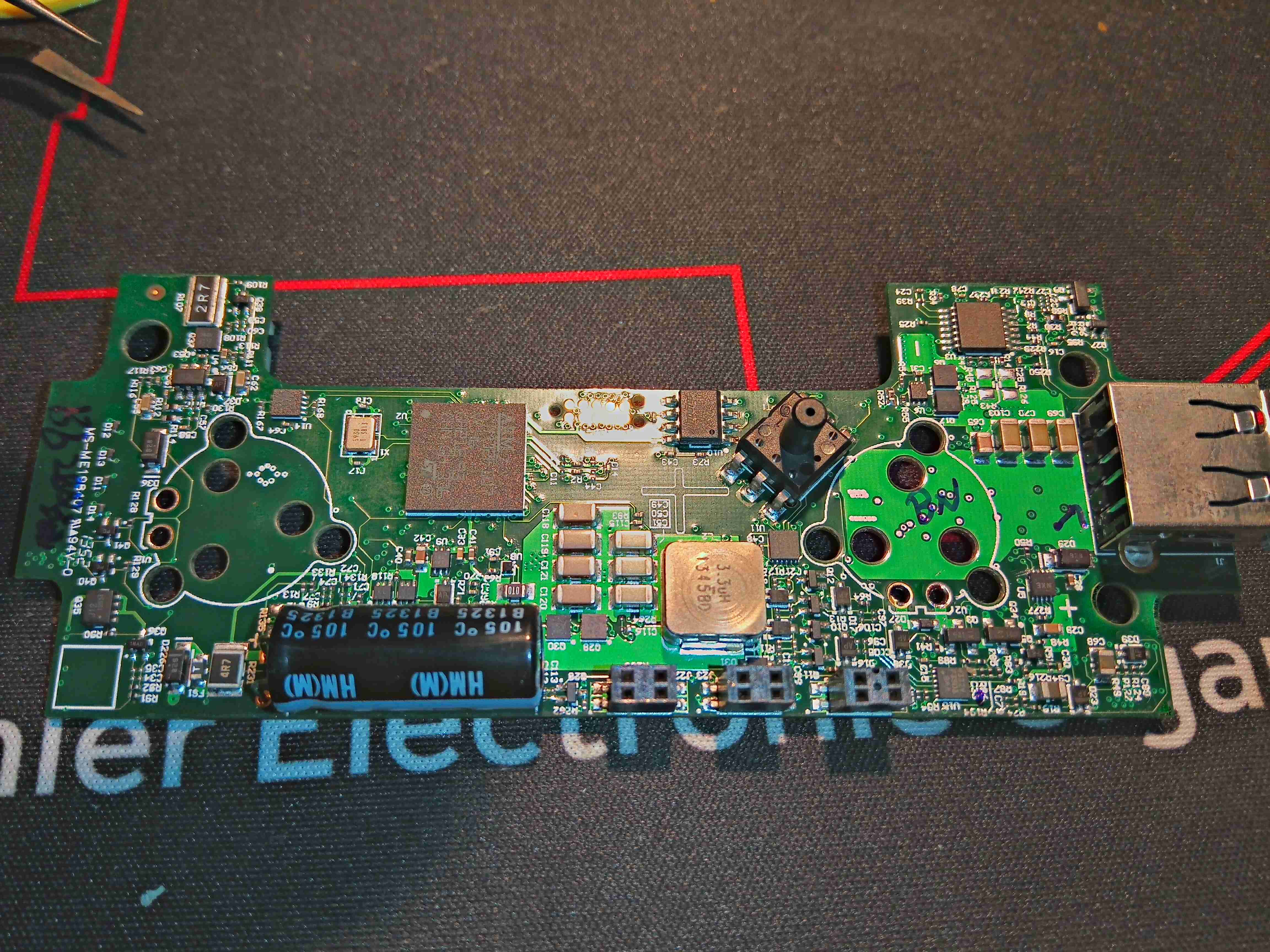
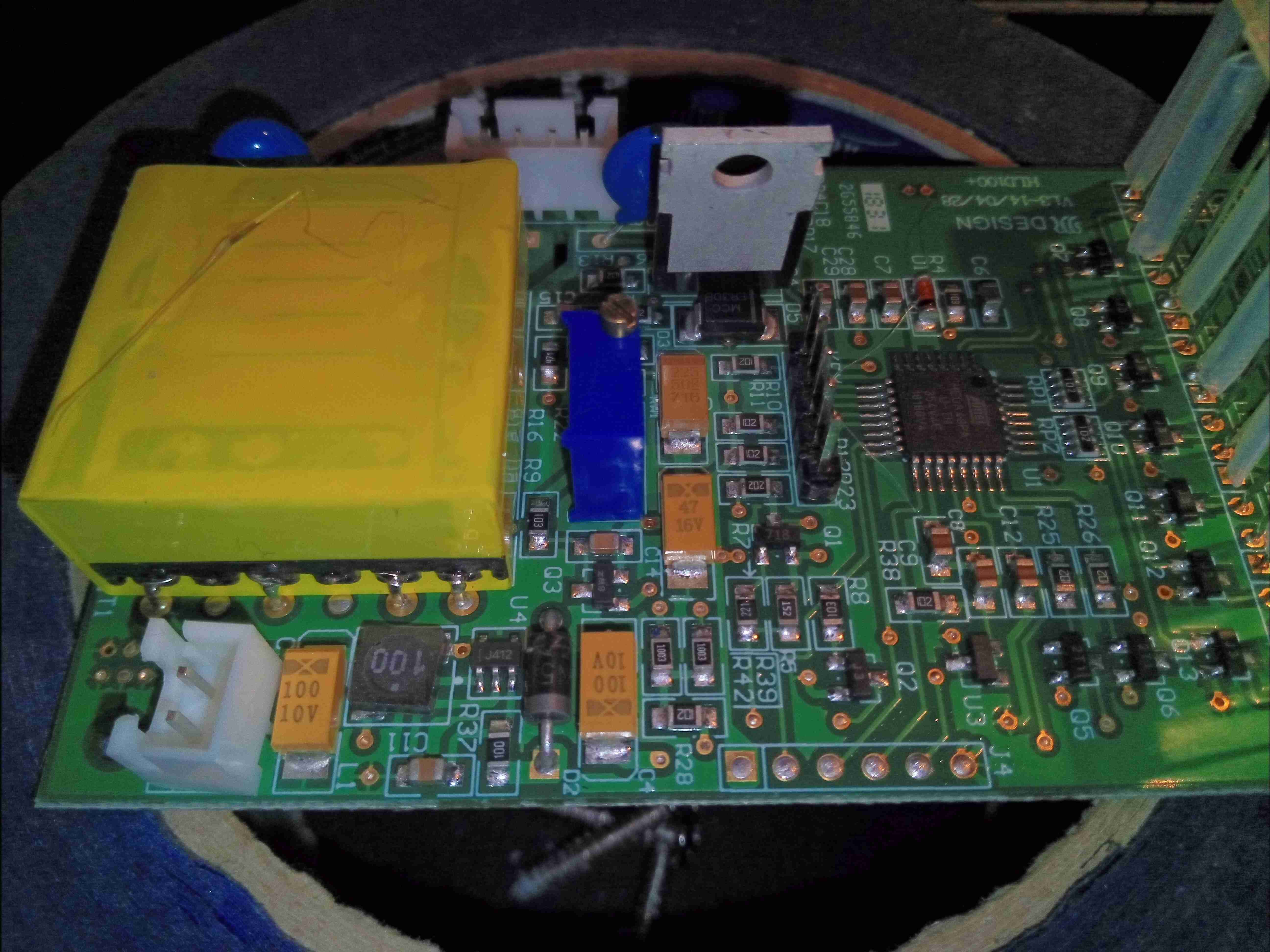
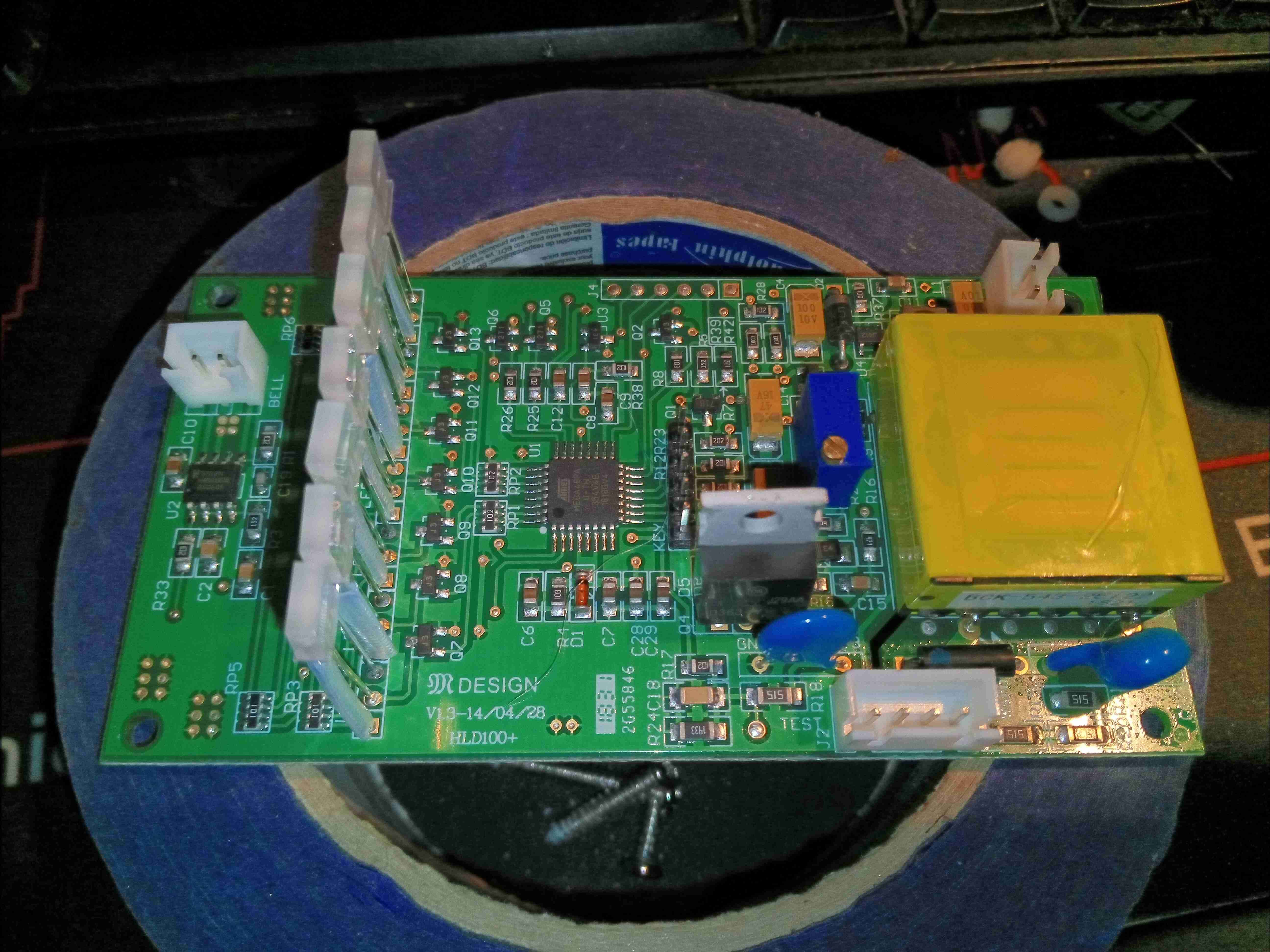
Main Control Board
On the left side of the projector is the main control PCB, with the video handling circuitry.
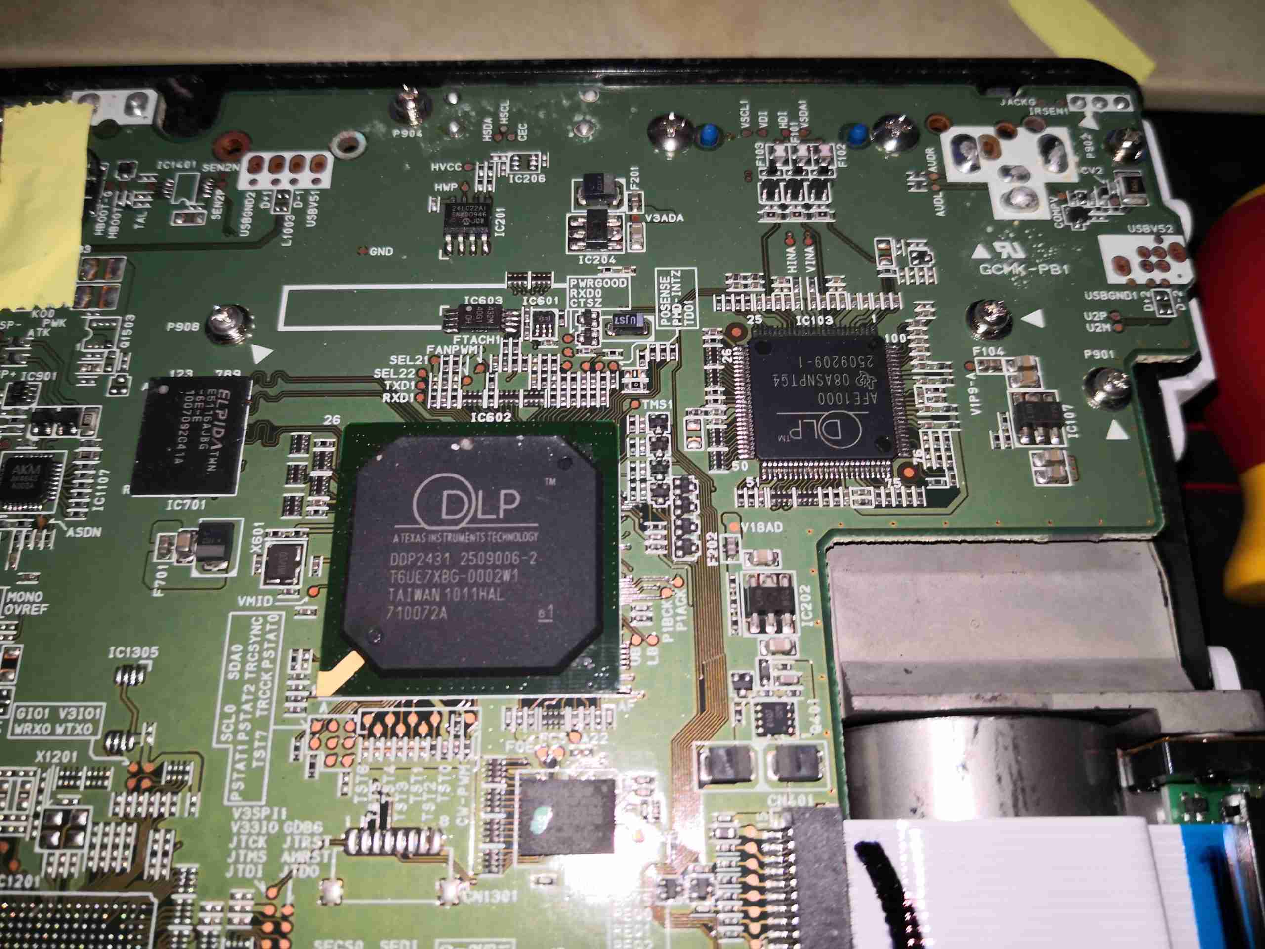
DLP Chipset
At the top of the board is the main DLP image processing chipset, these two components are actually custom parts, so no datasheets are available. The main DLP IC has some DRAM & a Spansion serial flash for firmware storage. There’s also a small audio amplifier on the left to drive the onboard 2W speaker.
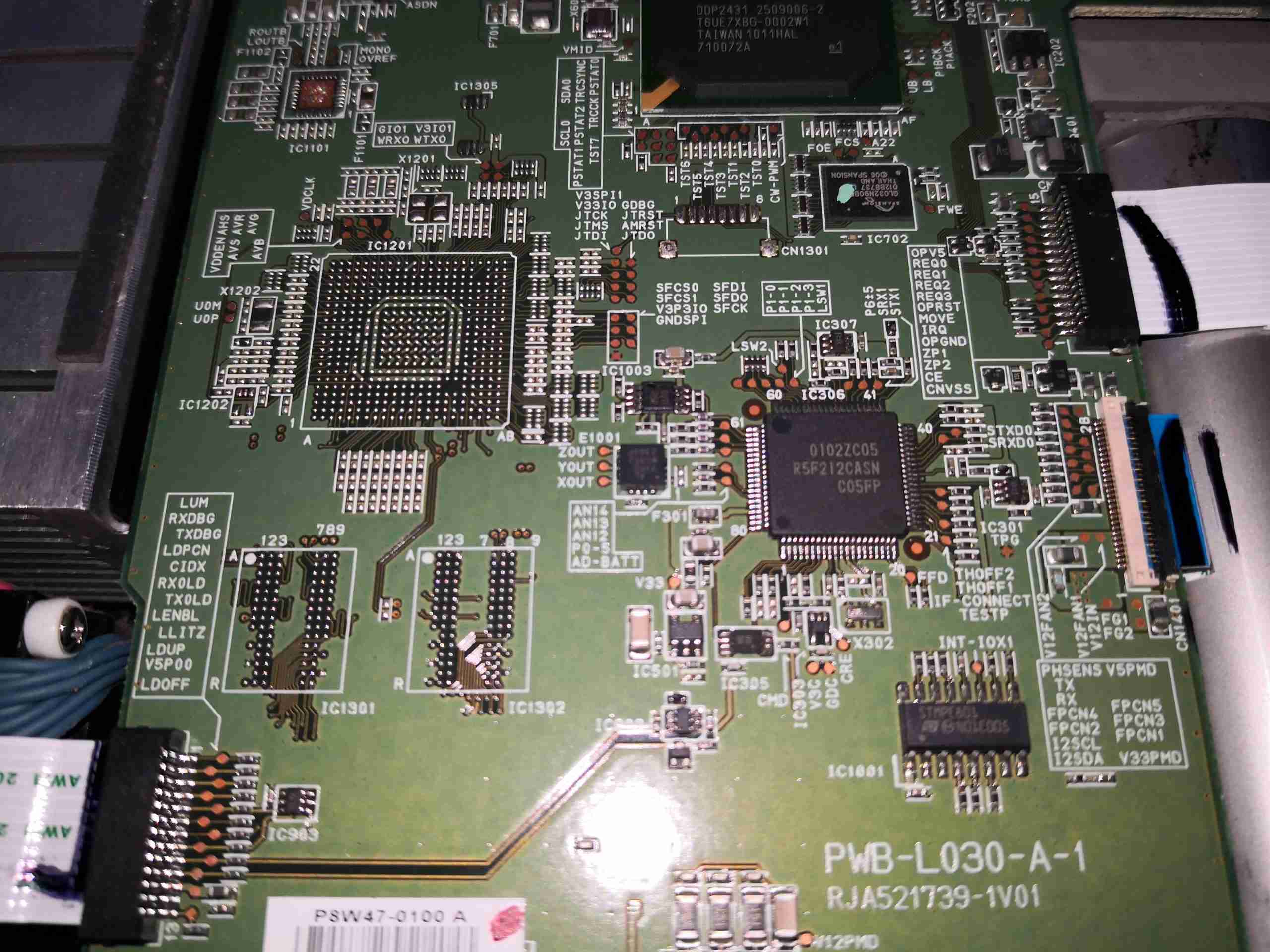
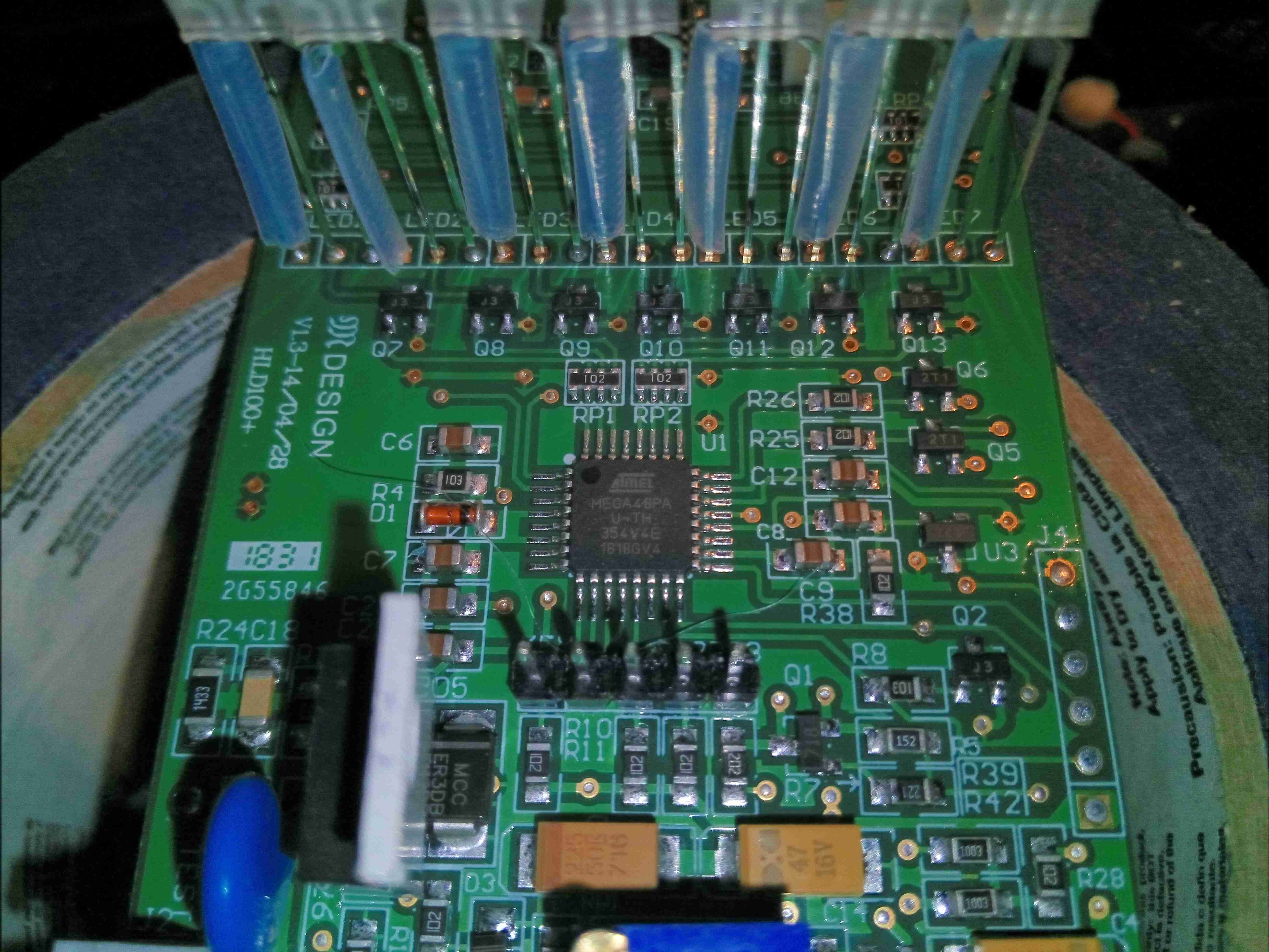
System Microcontroller
Further down the board sees an unpopulated BGA footprint, with more space for DRAM. The main system microcontroller is on the right, a Renesas part.
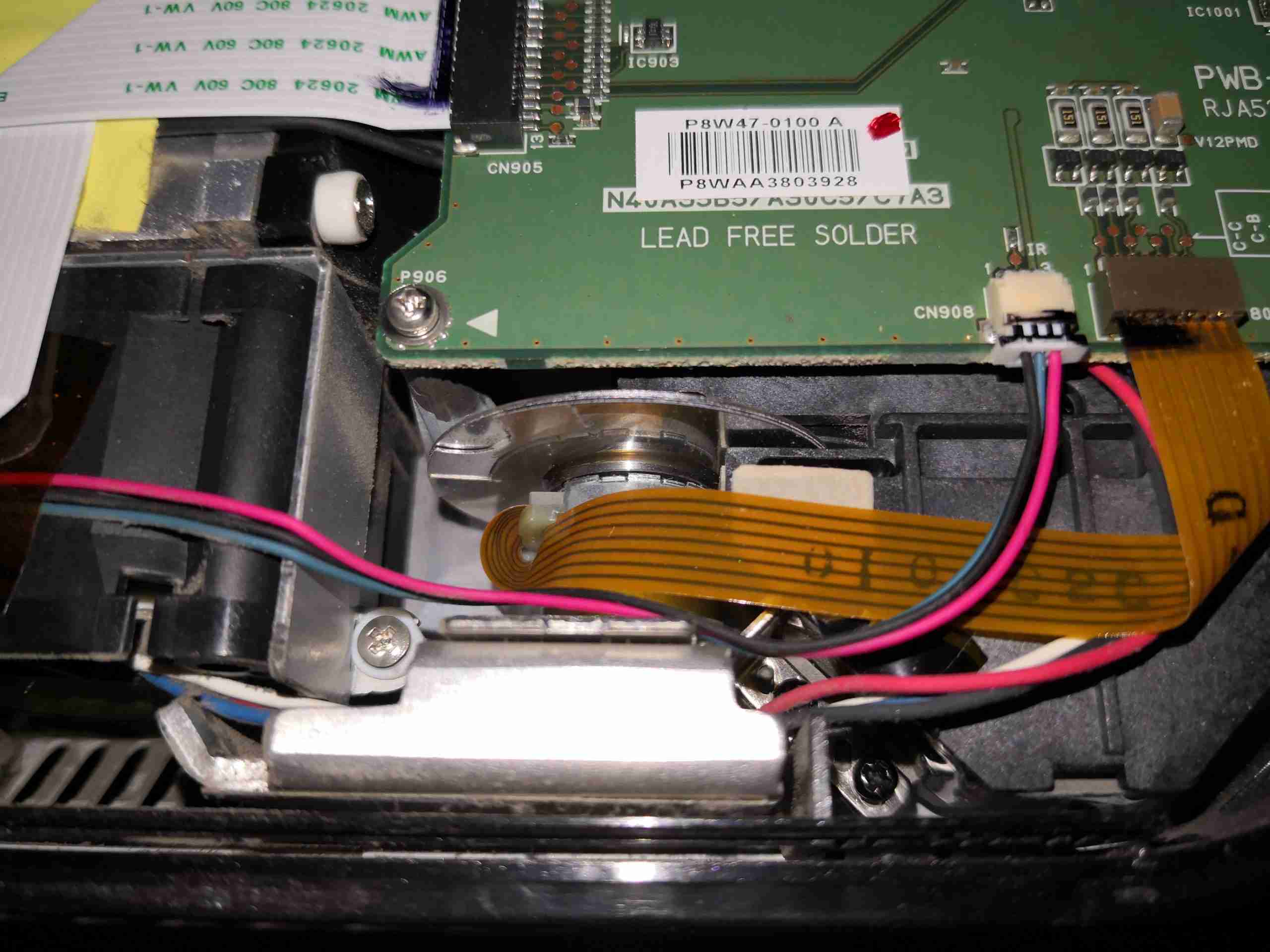
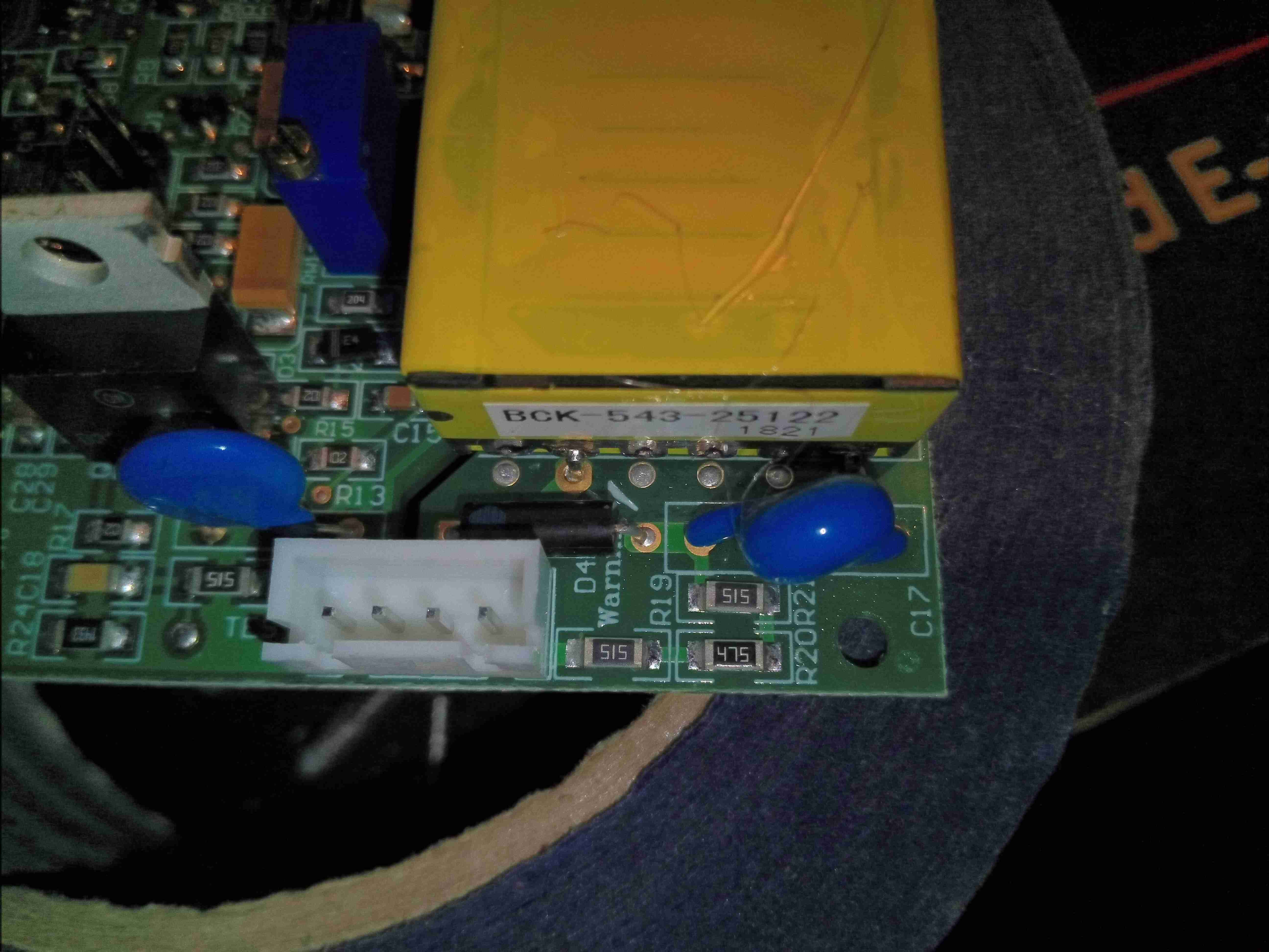
Phosphor Wheel Motor
Right at the bottom edge is the connector running off to the phosphor wheel drive motor.
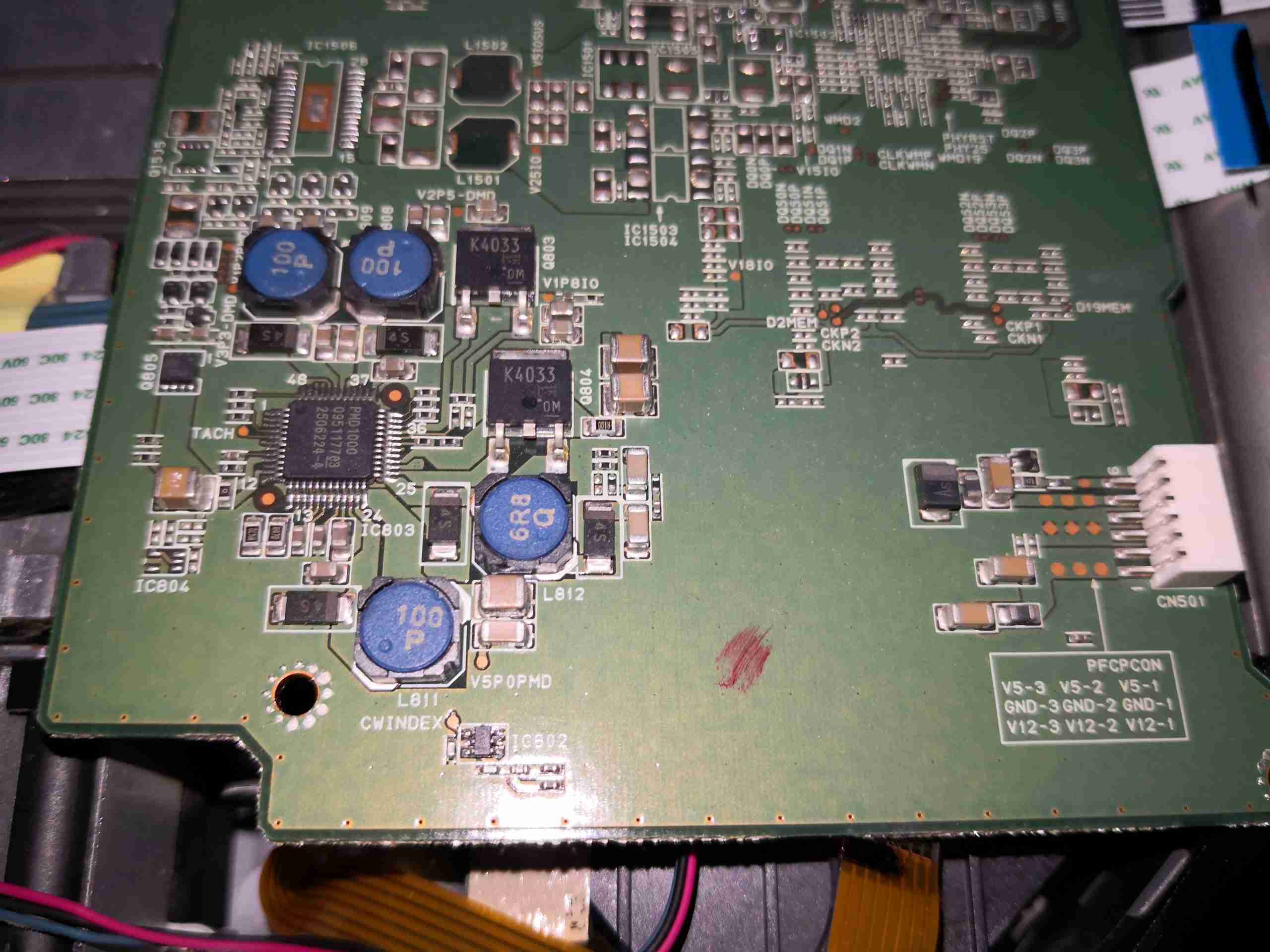
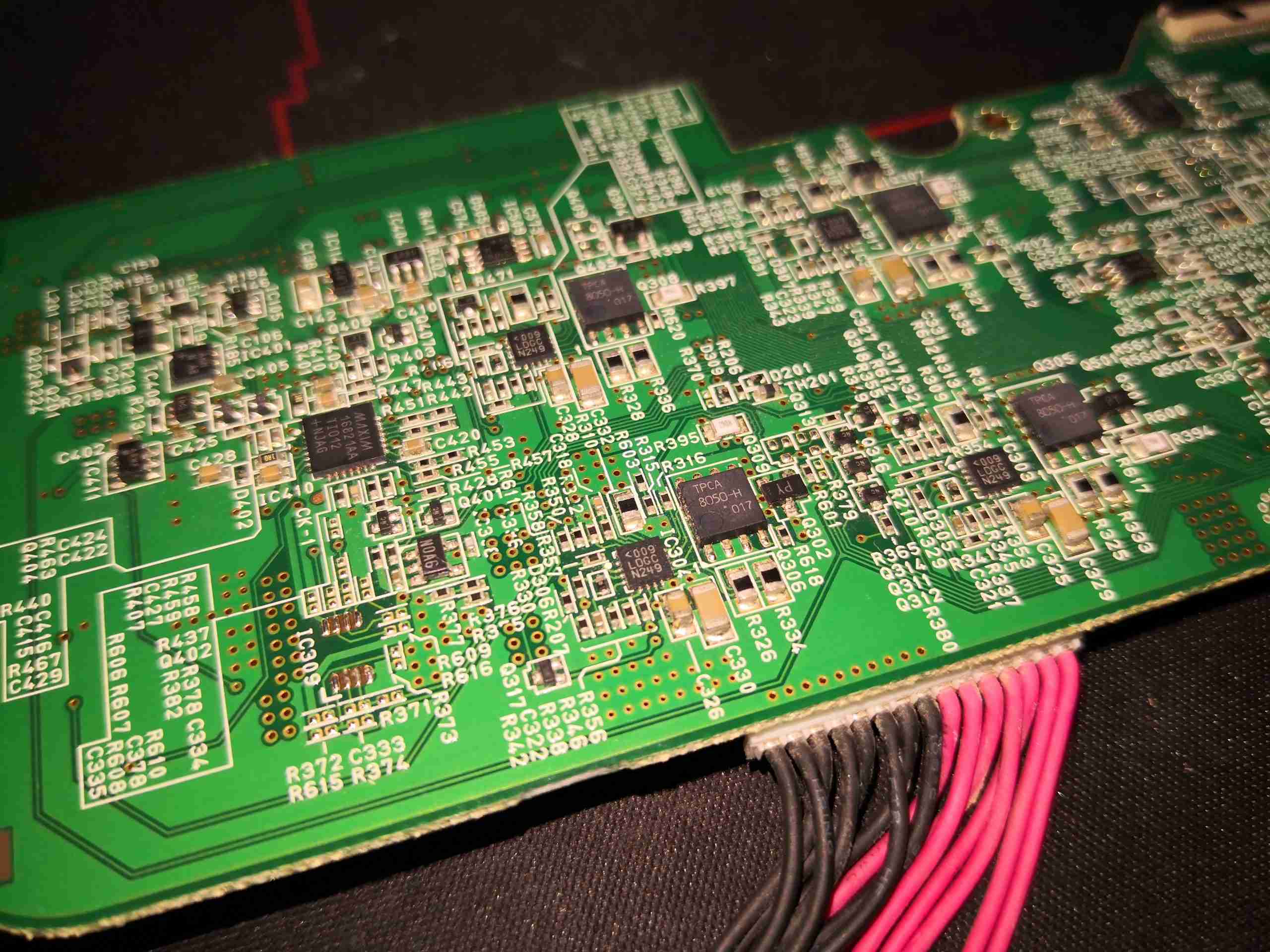
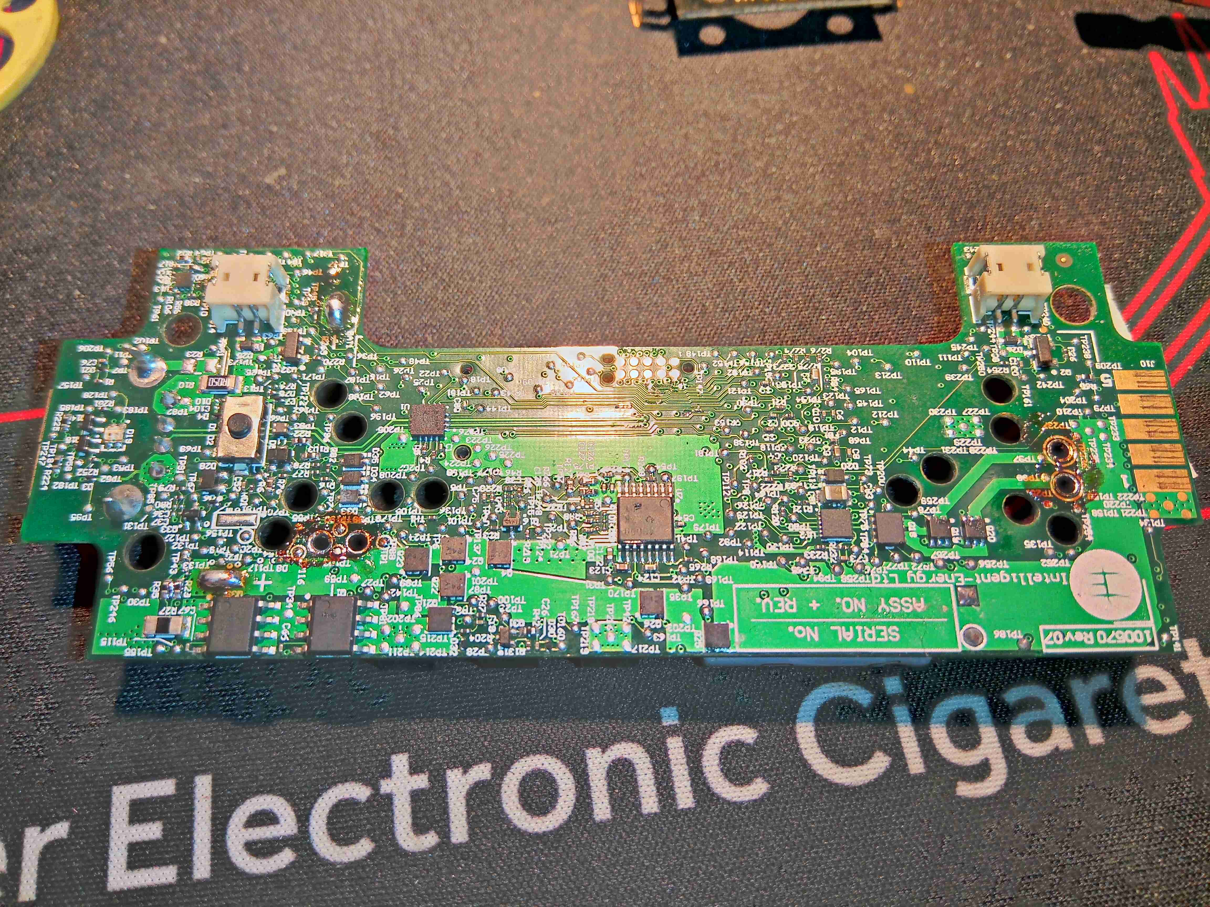
DC-DC Power Management
The reverse side of the board is pretty sparse, there’s quite a few passives & power control. Down towards the bottom surrounded by inductors is the system power management IC, the DLPA100. This takes the incoming DC 12v rail from the connector on the right side of the board & produces several supply rails for the internal logic: 1.1v 1.8v, 2.5v, 3.3, 5v & also contains the 3-phase brushless driver for the phosphor wheel motor. The main control board input power connector also has a +5v from the mains supply, for standby power. The main board signals the PSU to switch on the main +12v rail through a pin on this connector.
HDMI Interface Chipset
The other end of the board just has the connectors, a bit of glue logic & the HDMI interface chipset.
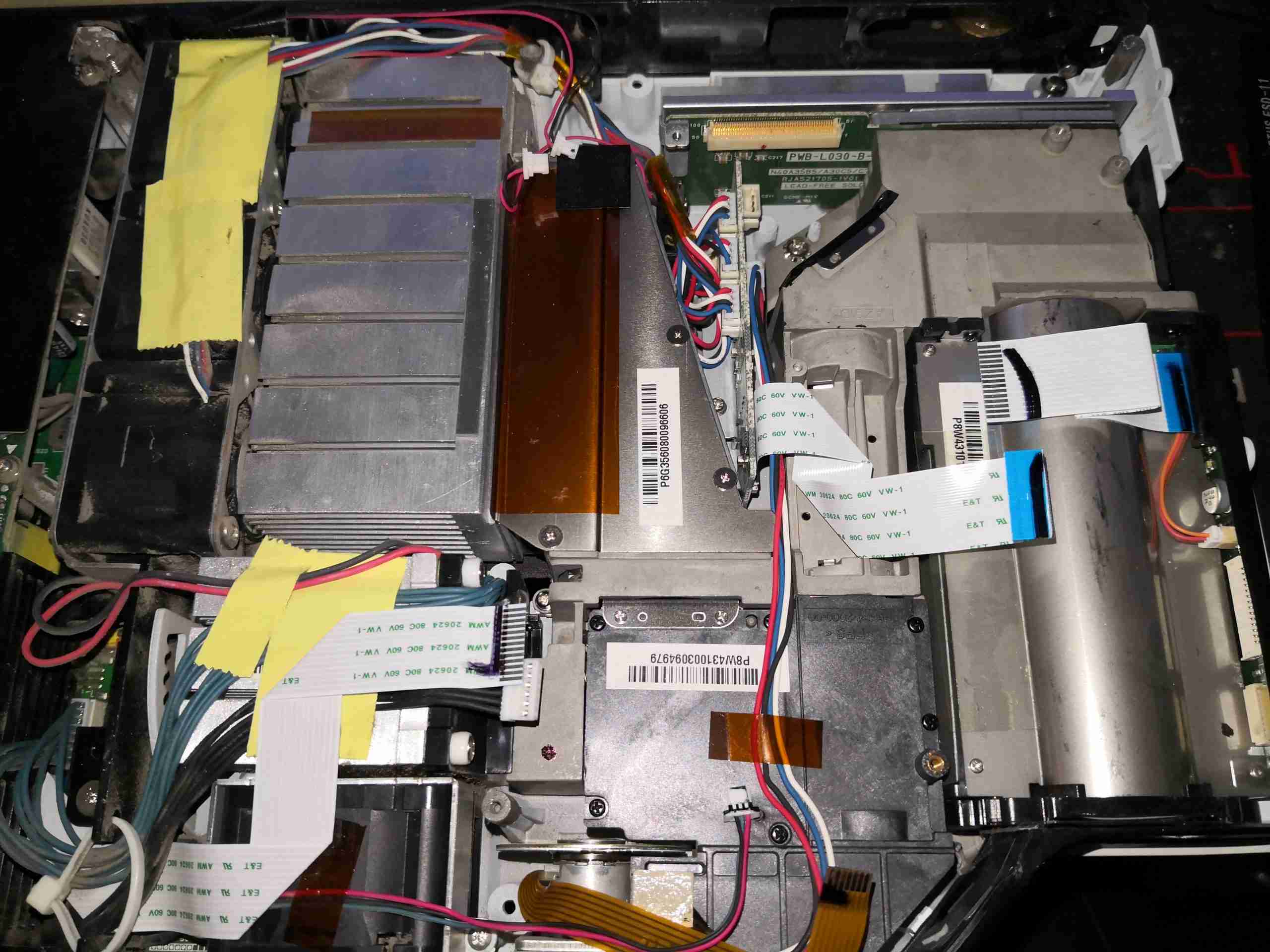
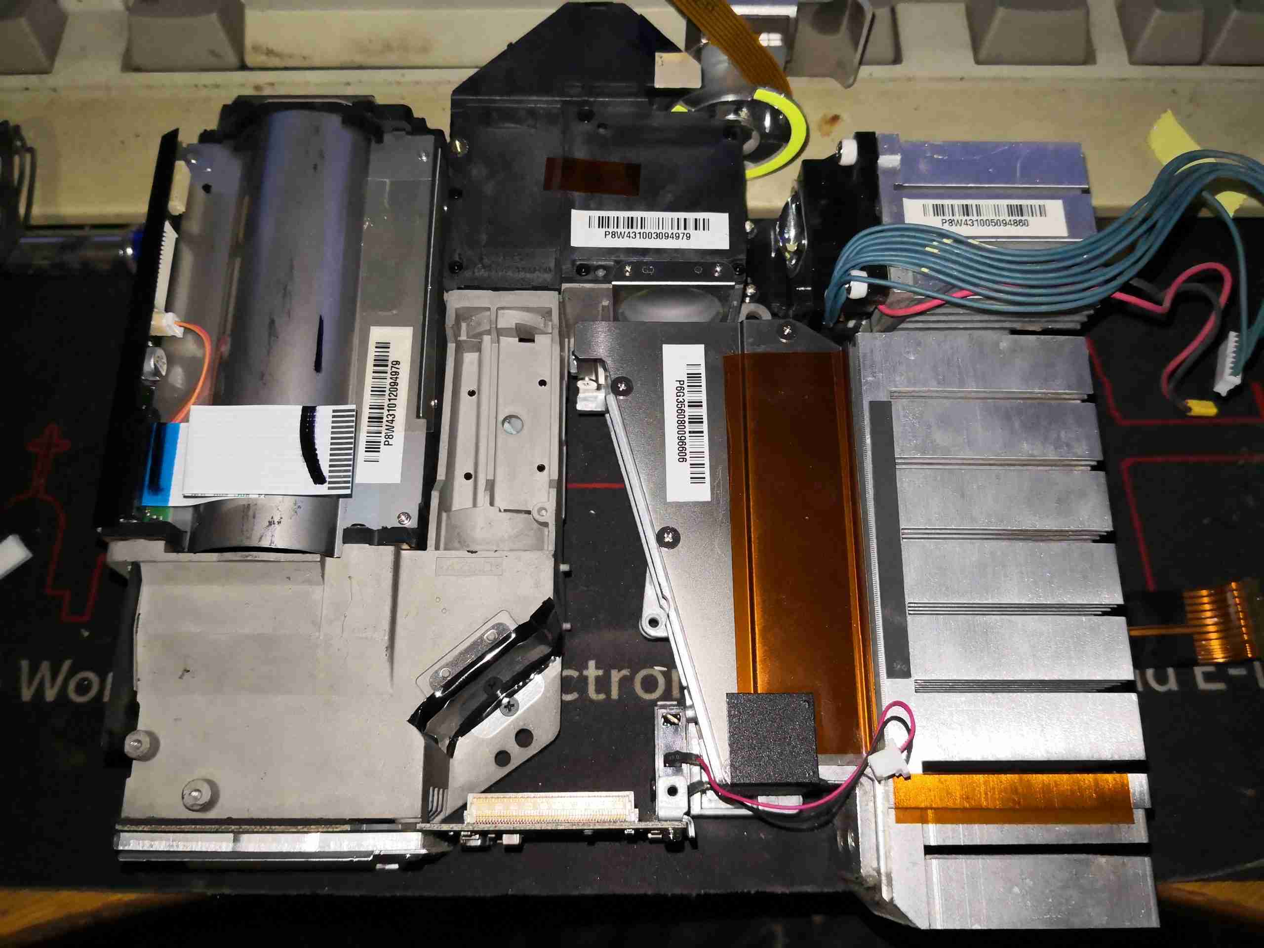
Main Board Removed
After unplugging all the connectors, the massive cast frame of the light engine is visible.
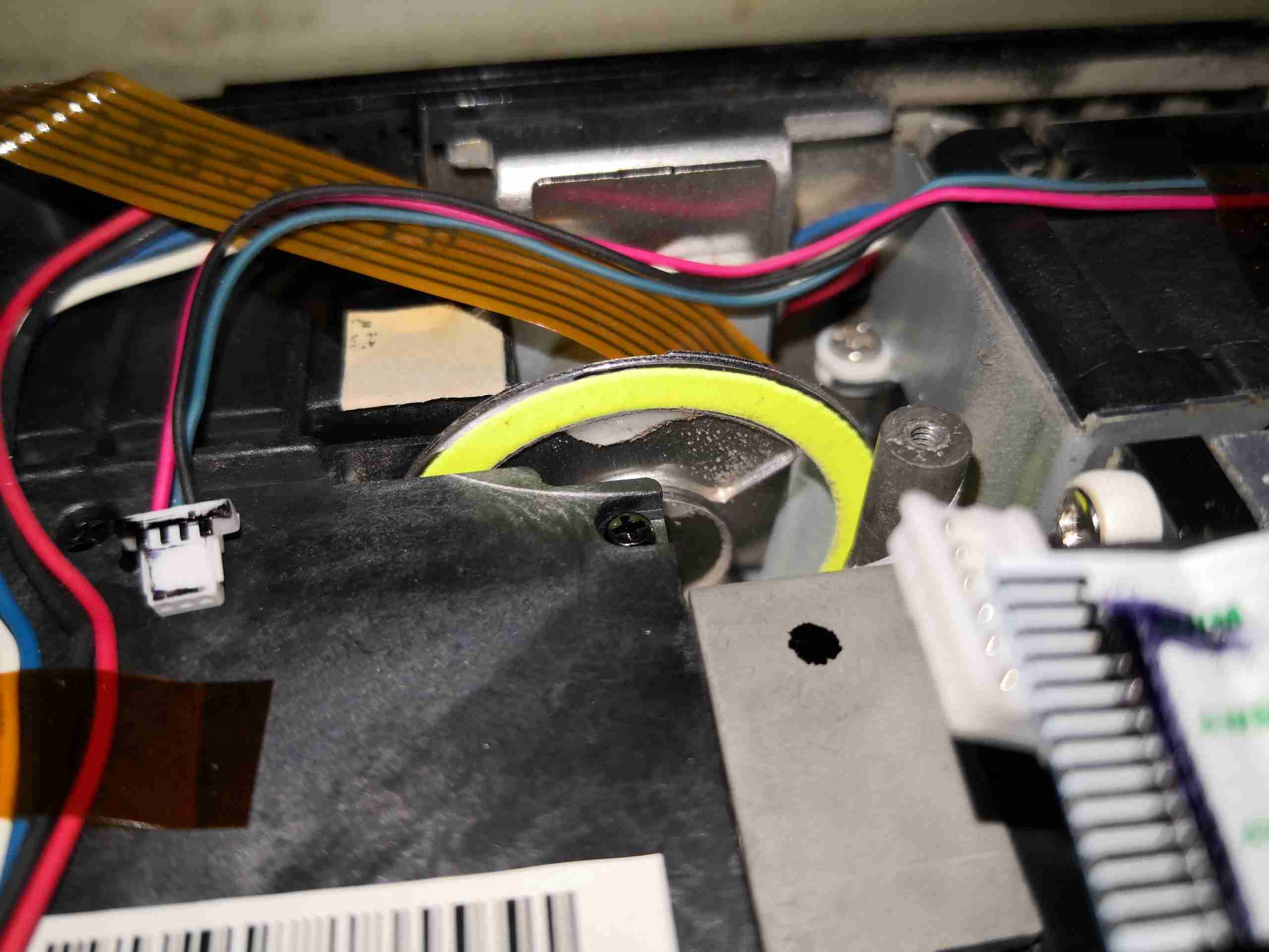
Phosphor Stripe
Here’s a closeup of the phosphor stripe around the edge of the wheel. This takes the 445nm light from the laser module, and converts it into green. There’s also a frosted glass section of the wheel to pass some blue for the image. The reason for the phosphor being in a large stripe on the wheel is load spreading – there’s several watts of optical power focused down to a very small spot on this phosphor, and would overheat quickly if it wasn’t moving.
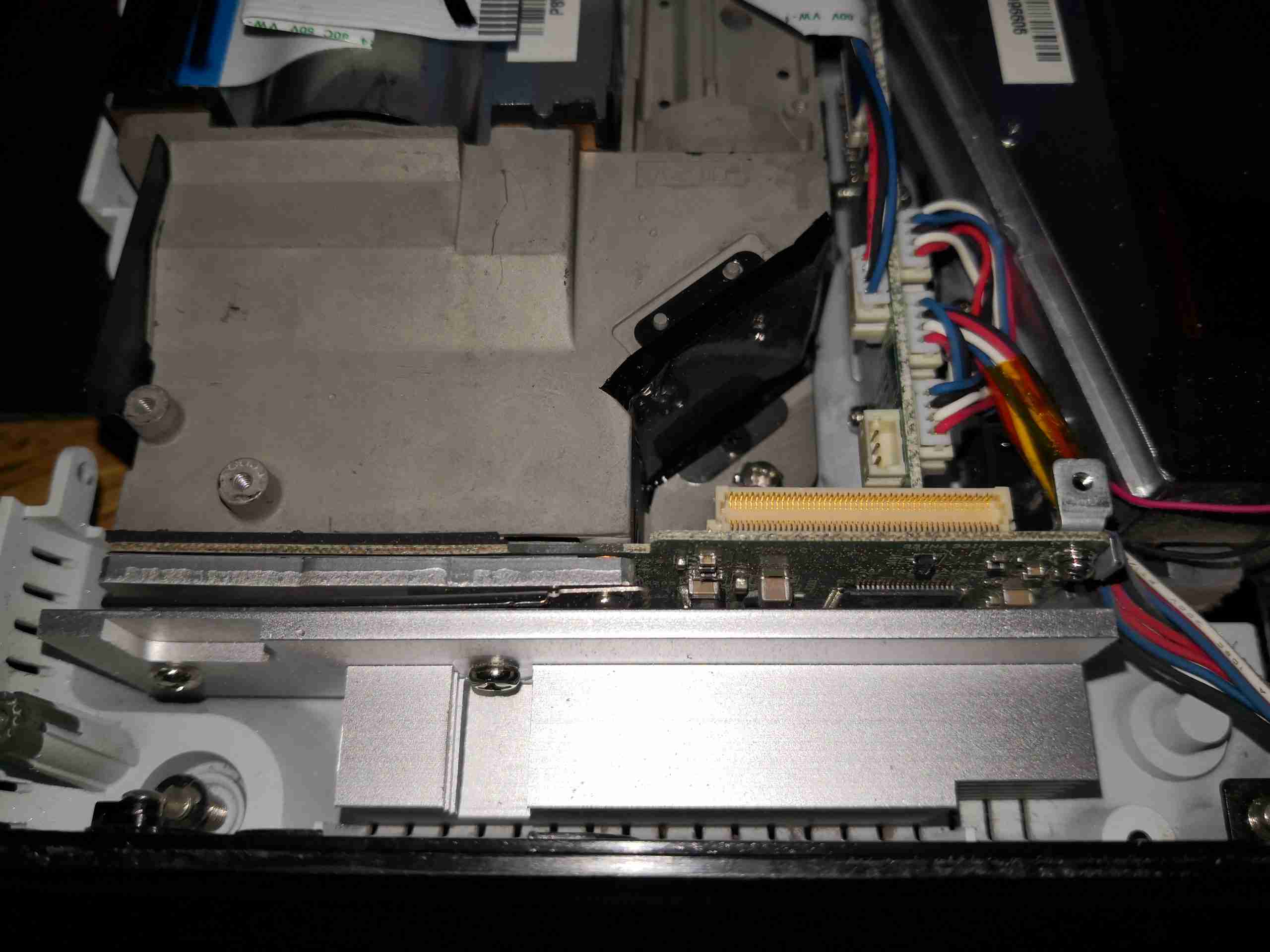
DLP Frame
At the back of the light engine is the DLP module, with it’s substantial heatsink.
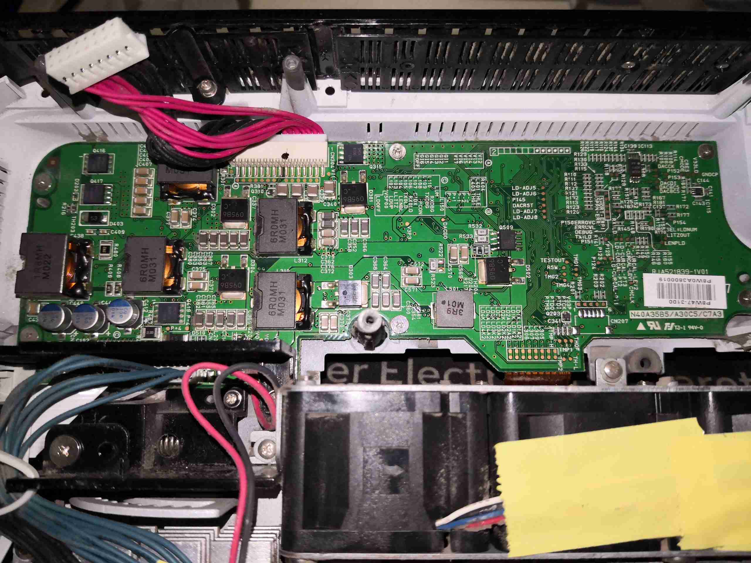
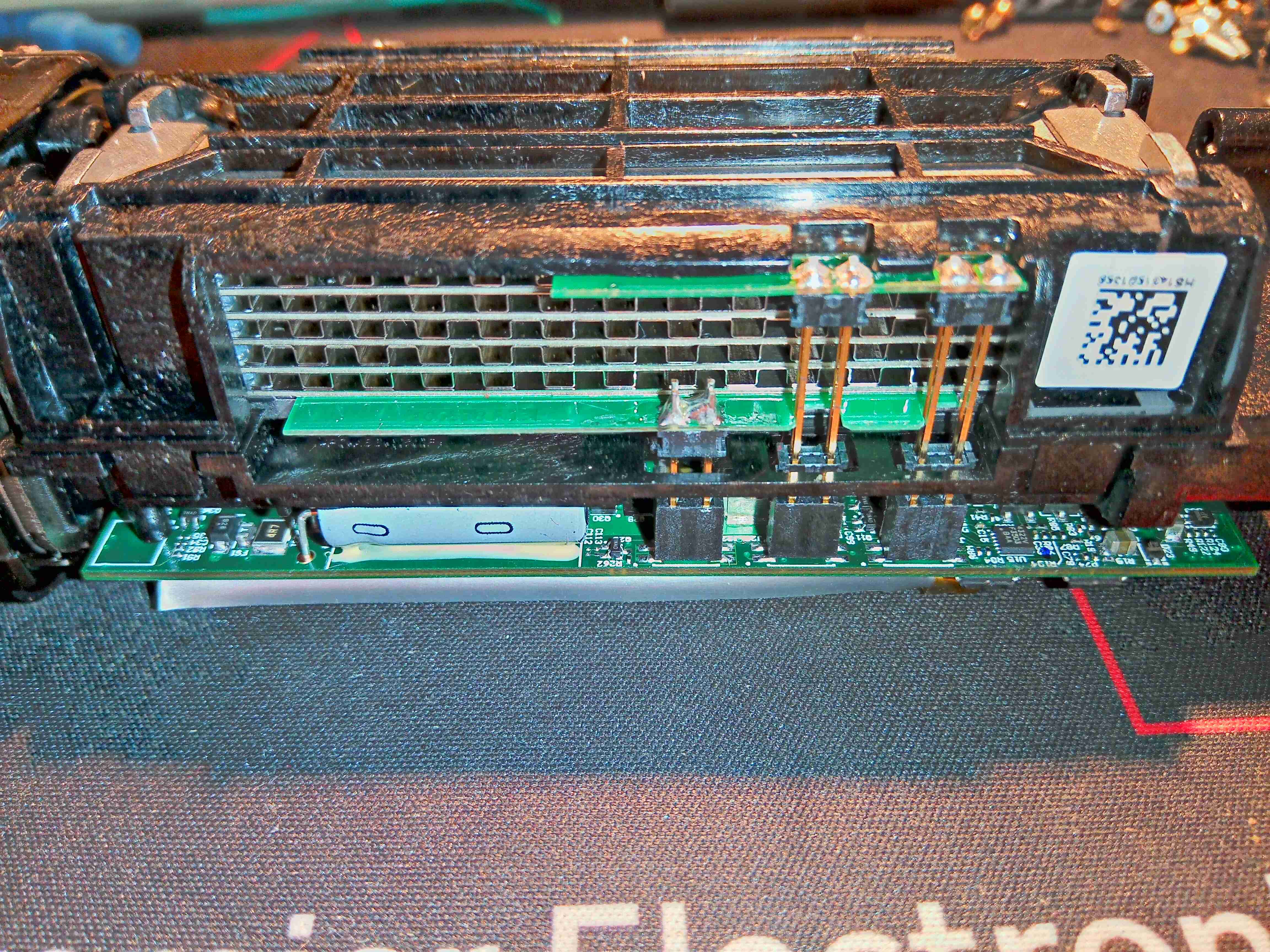
Light Source PSU Board
Hiding under the mains PSU, is the light source control PCB. This contains several DC-DC converters, which run the 4 strings of laser diodes, the large Phlatlight Red LED & it’s associated TEC cooler. This board takes the incoming +12v from the mains PSU through the multi-way loom at top centre. There are multiple cores on this connector to spread the load – at normal brightness, in Eco mode, I measured the power consumption at about 8.5A at 12v input for the entire projector.
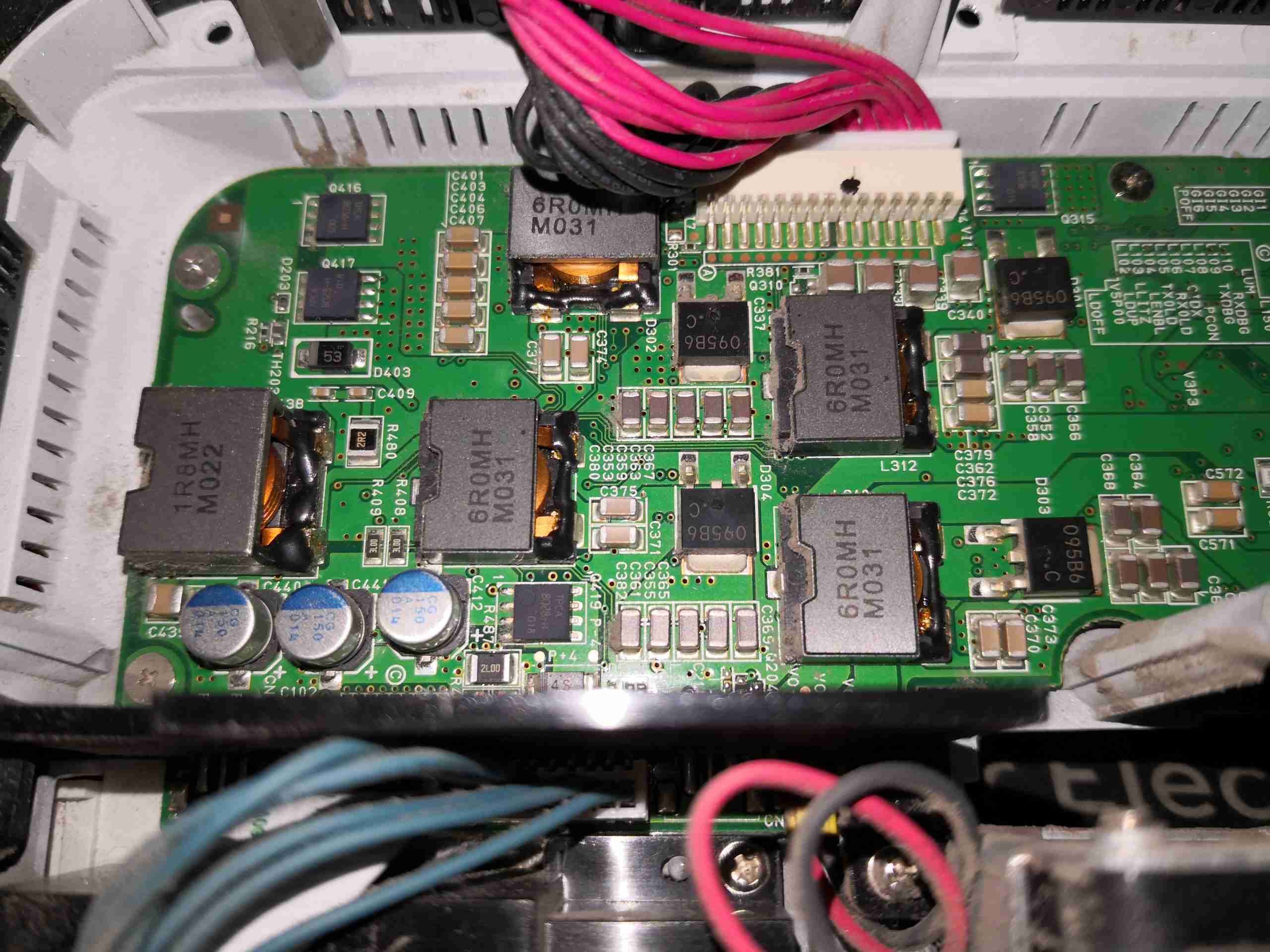
DC-DC Converters
The left side of the board is dedicated to the high power section of the controller. There’s a power inductor for every channel.
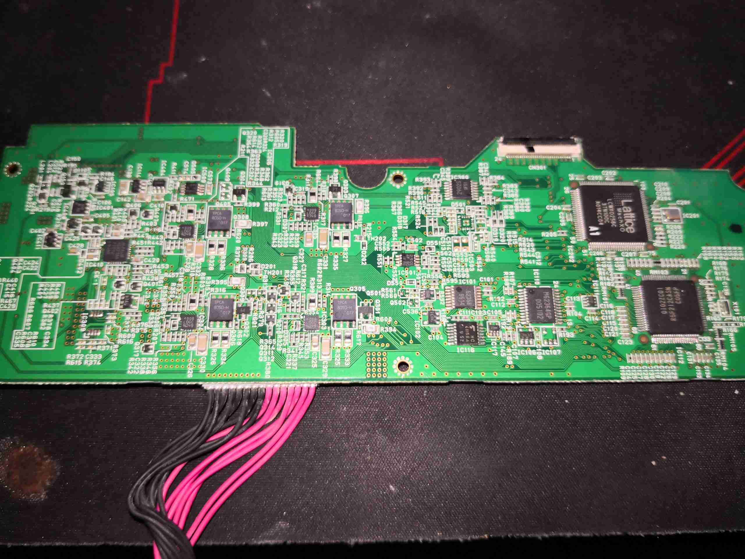
Light Source Drive Board
The other side of the board is very heavily populated with components.
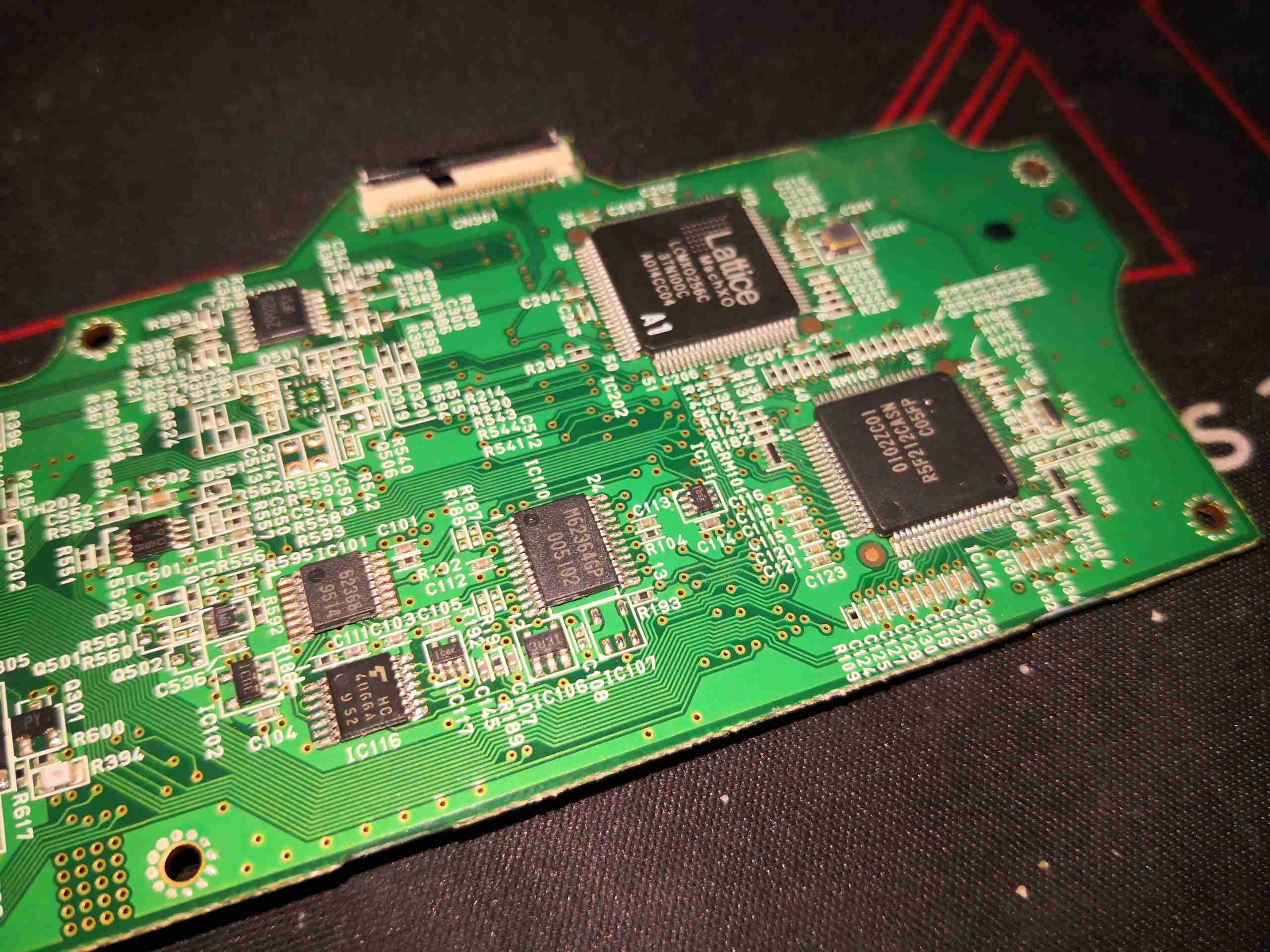
Control Logic
The right hand side has the control logic, a Lattice CPLD, and another Renesas Microcontroller. There’s also some glue logic here & a dedicated DA converter.
Power Drivers
The other end of the board has the power drive control logic. There’s a MAX16821AA LED buck driver for the Red LED, and 4 drive ICs for the laser diodes, which are marked <009 LDGC N249. I haven’t been able to find anything about these, so they may be custom.
DLP Light Engine
Removing some screws allows the entire optical assembly to be removed from the lower shell. This may be mostly manufactured from a magnesium alloy from the rather low weight.
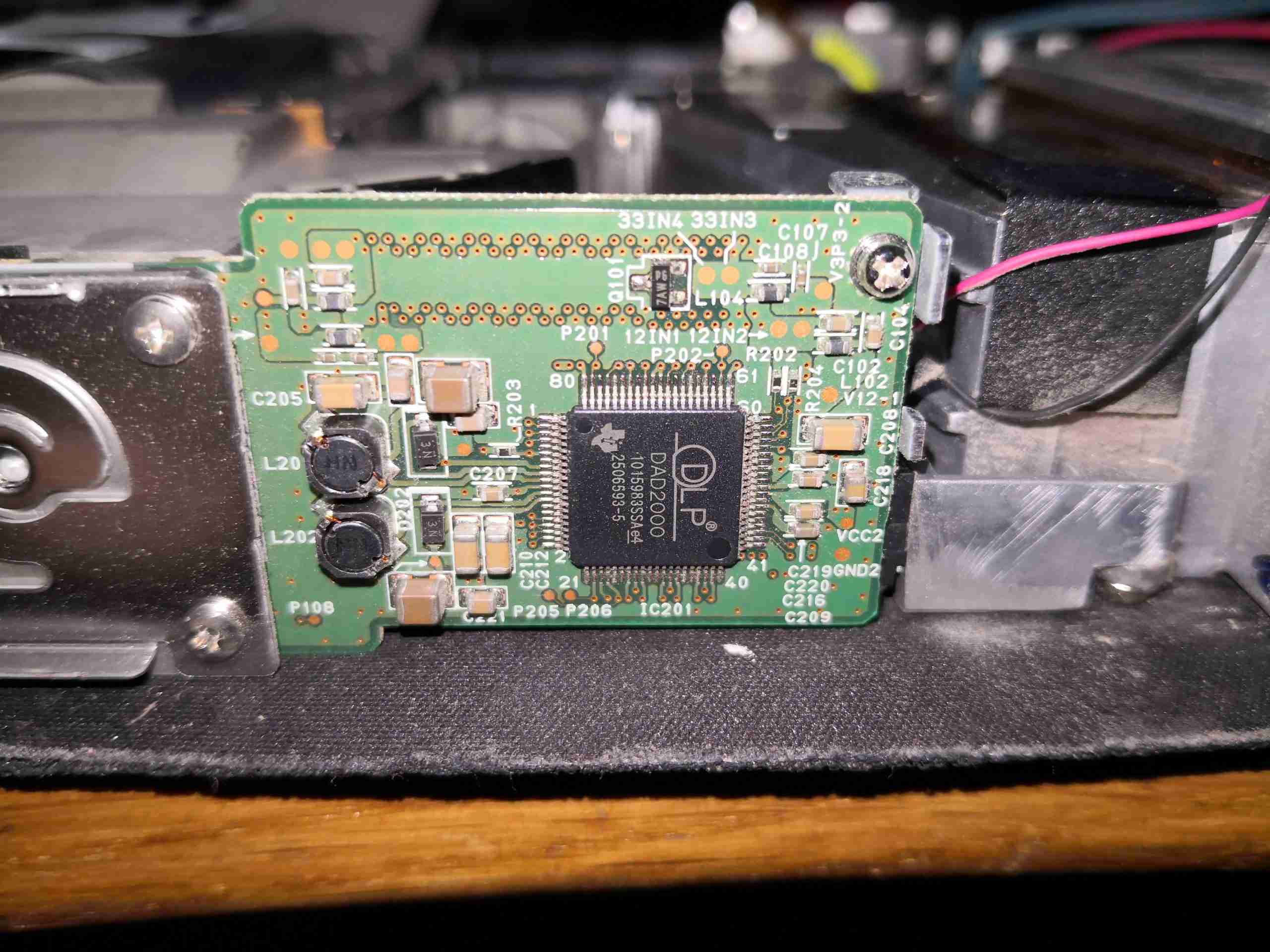
DLP Board
On the back of the DLP module is the DLPA200 Micromirror Driver IC. This generates the high voltage bias supplies for the DMD chip (+/-28v) from the 12v rail, generates all the timing waveforms required for the DLP chip. There’s a couple of power inductors for the onboard regulators. Video data is sent from the main image processing chipset to the DMD chip via 2 channels of LVDS.
DLP Mount
Now the heatsink has been removed, the rear of the DLP chip can be seen, with the remains of the thermal pad. The mount for the heatsink is sprung, to accommodate thermal expansion.
Red PhlatLight
The Red light required to create a colour image is generated by a giant LED, more on this one later.
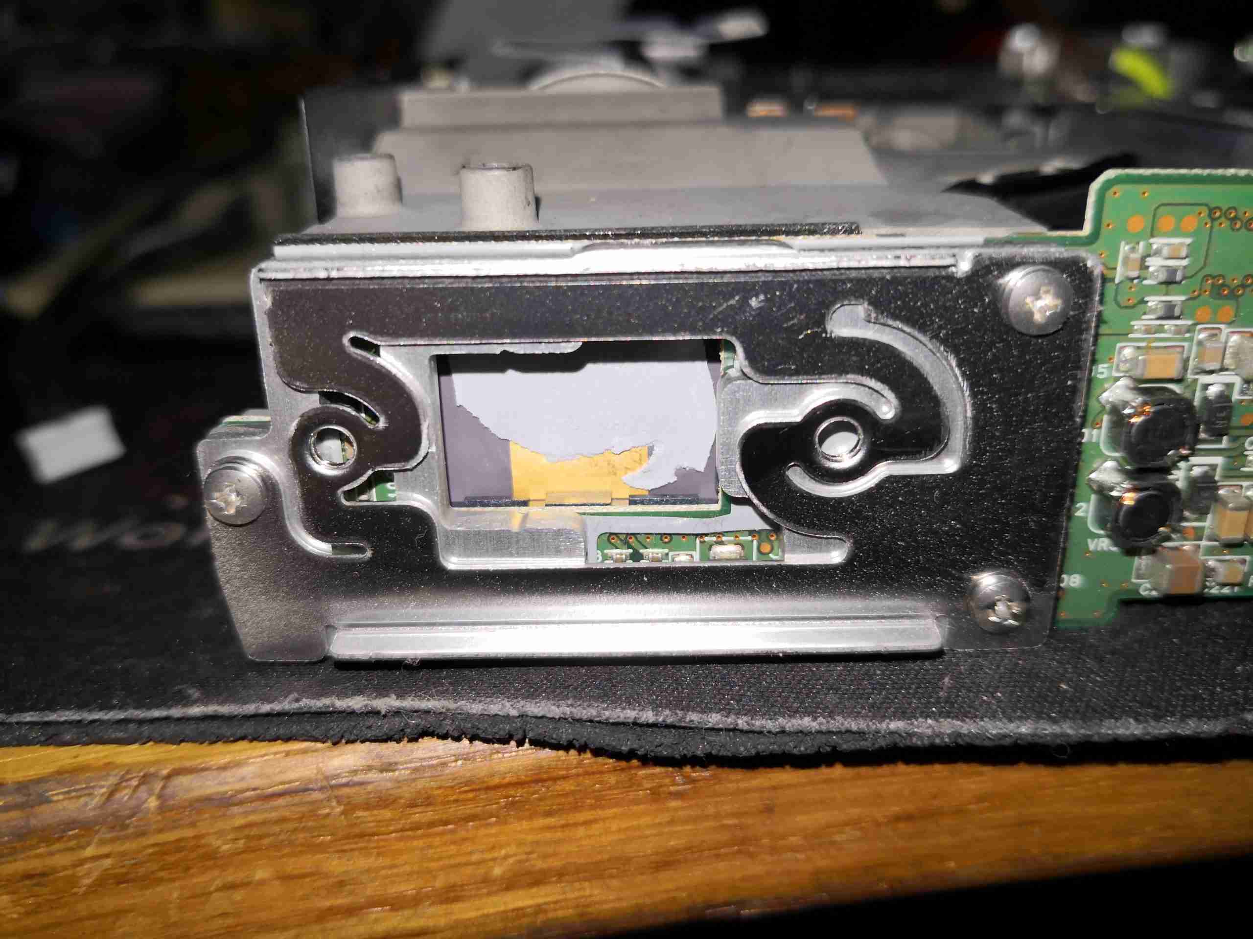
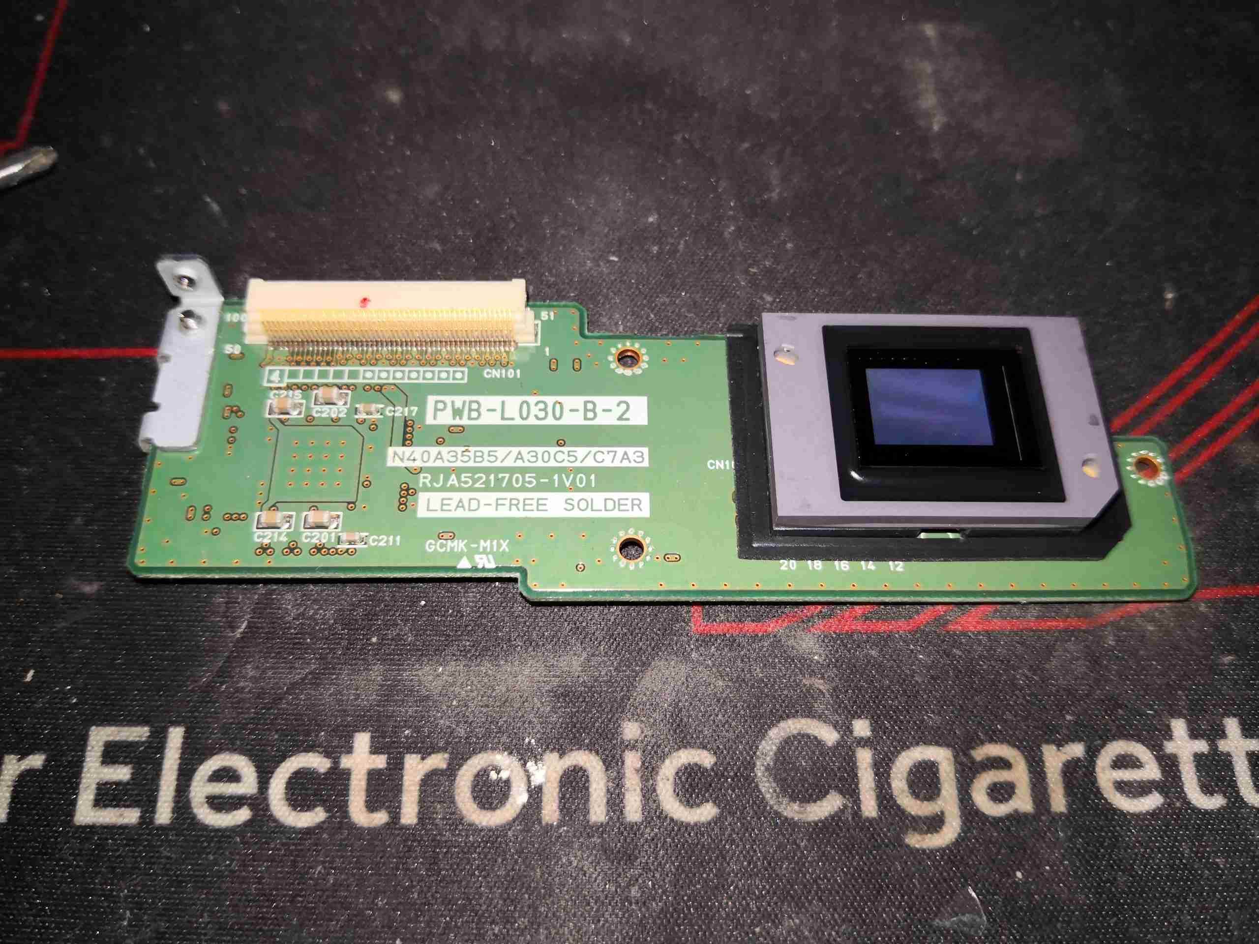
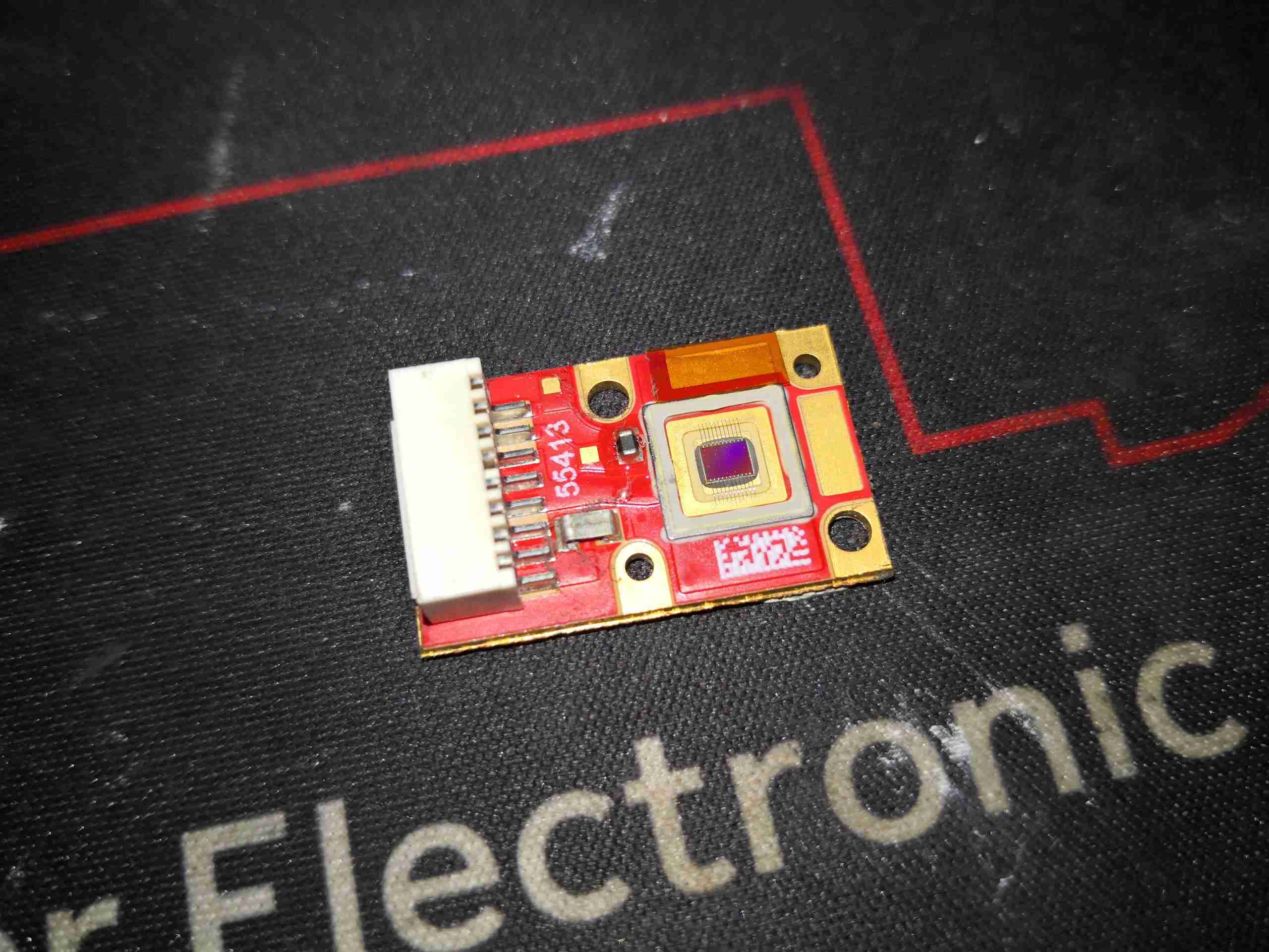
DLP Removed
Here’s the DLP board removed from the projector with the micromirror surface visible. This DLP has many dead pixels, hence the decommission at ~4500 hours of operation.
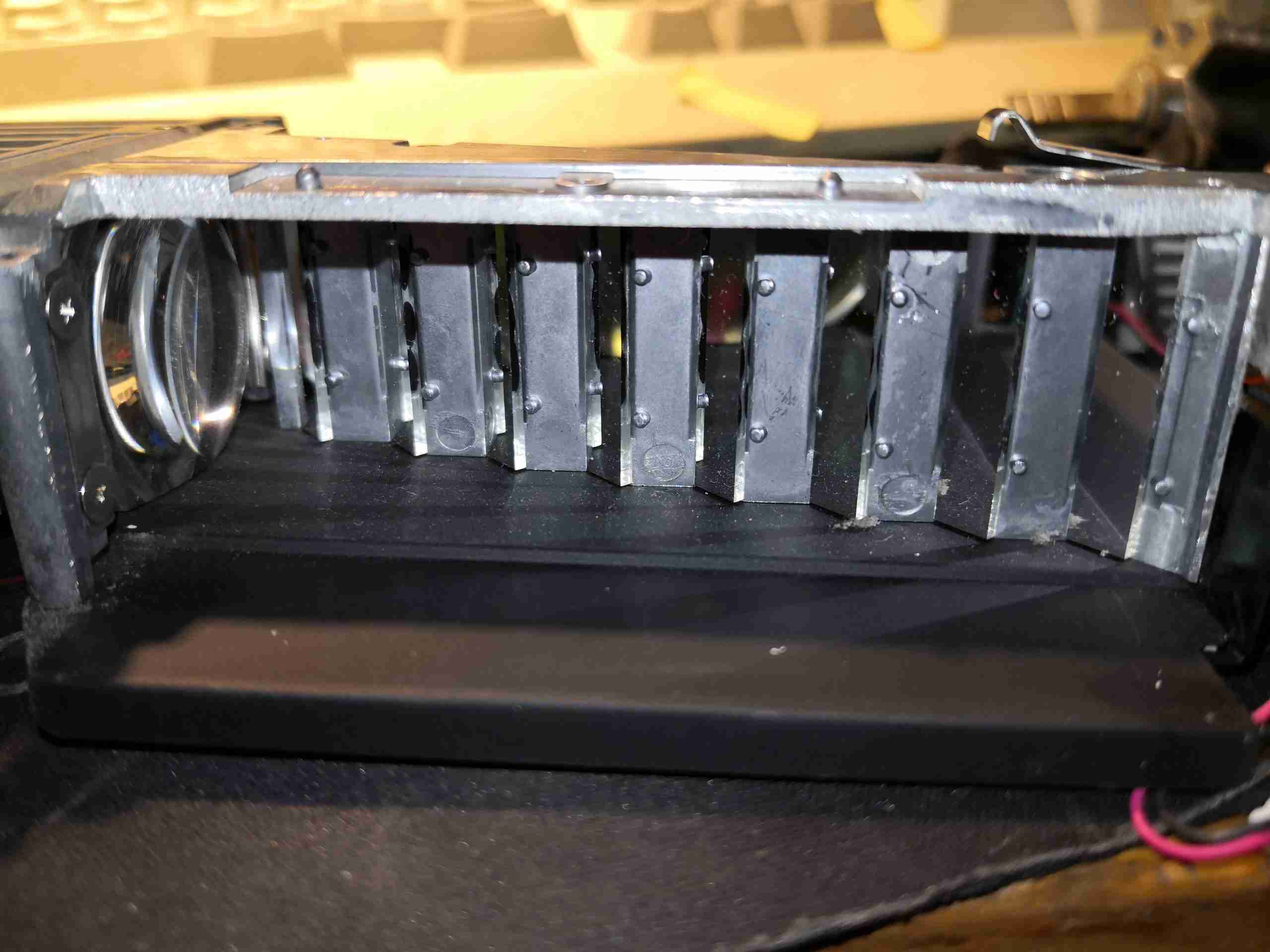
Laser Beam Combiner
The 24 laser diodes have their beams combined by this knife-edge mirror assembly, turning the beam through 90° to the lens on the left, which focuses the 24 beams down to the optics engine.
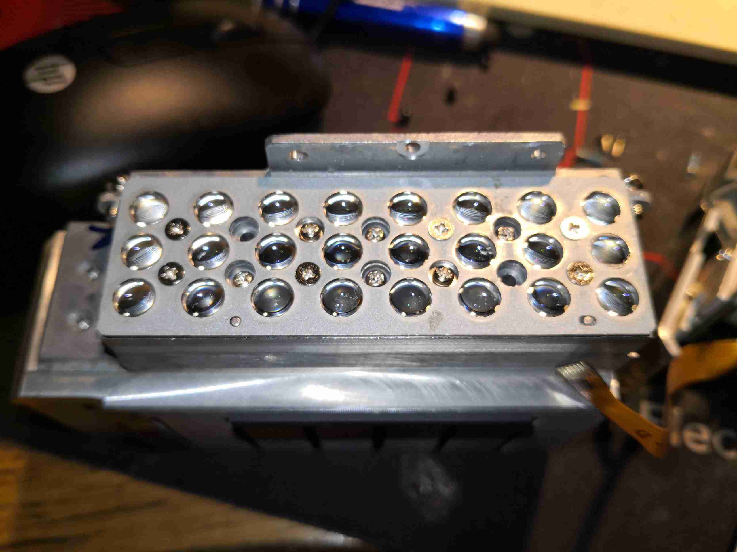
445nm Laser Array
Removing the beam combiner from the array allows the 24 diodes to be seen, mounted under their collimating lenses. This is one beast of a laser unit!
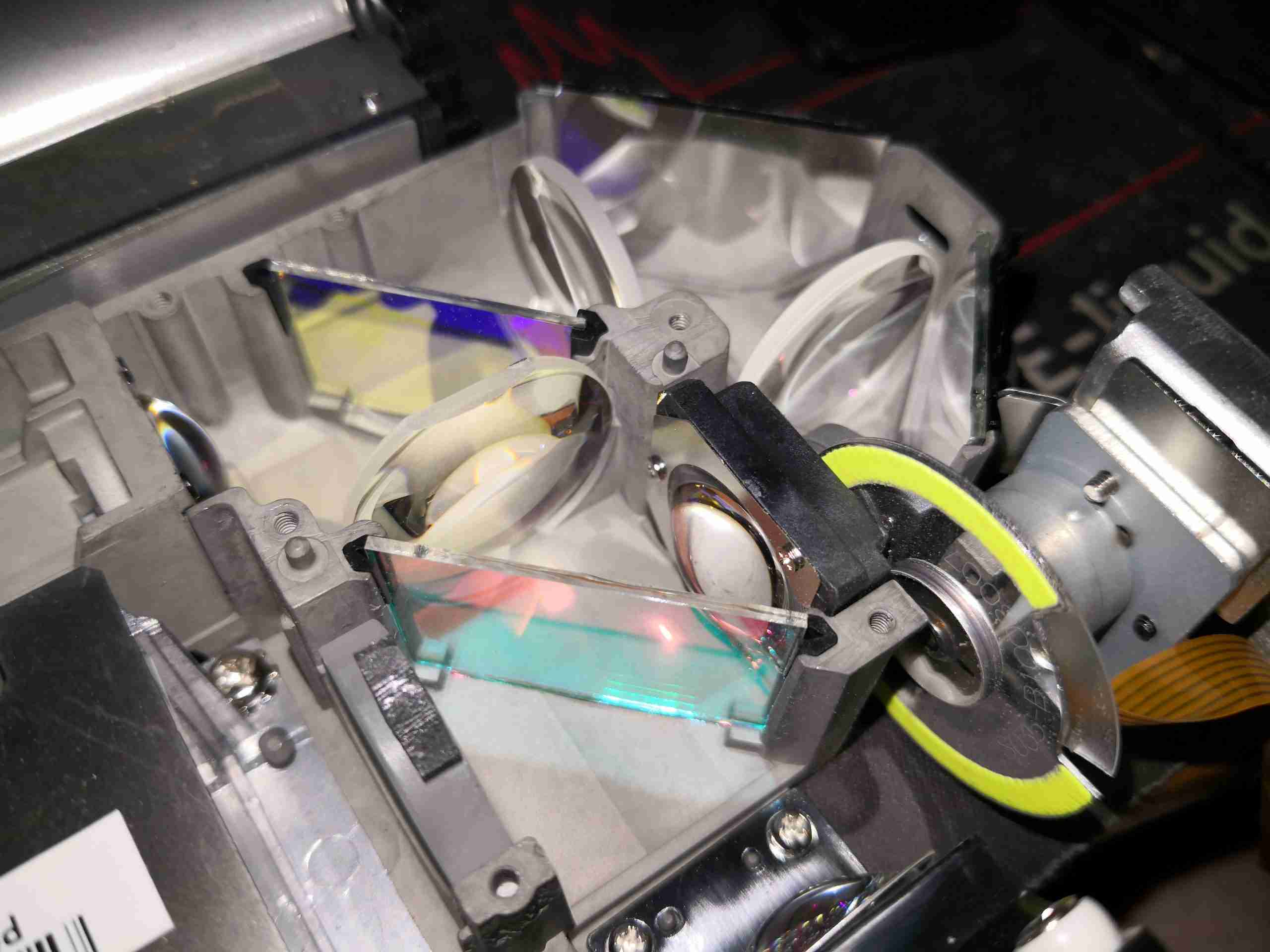
Dichroic Optics
Taking the cover off the optics assembly allows the main optical path to be seen. The blue laser comes in a bottom left, through the lens, the red LED comes in bottom right. The pair of dichroic mirrors manage the light path for the red & green light, while passing the blue straight through.
Optical Path
Here’s another view of the optical path, with both light sources visible.
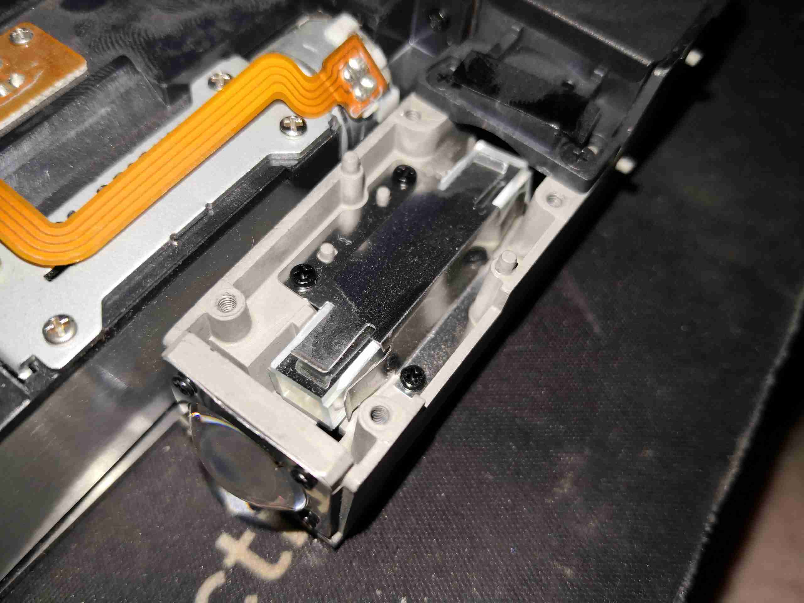
Light Homogenizer
After the light source, is the homogeniser – this tunnel of 4 mirrors facing each other evens out the light beam & removes all coherence from the laser light. This is important to not have any speckle in the image.
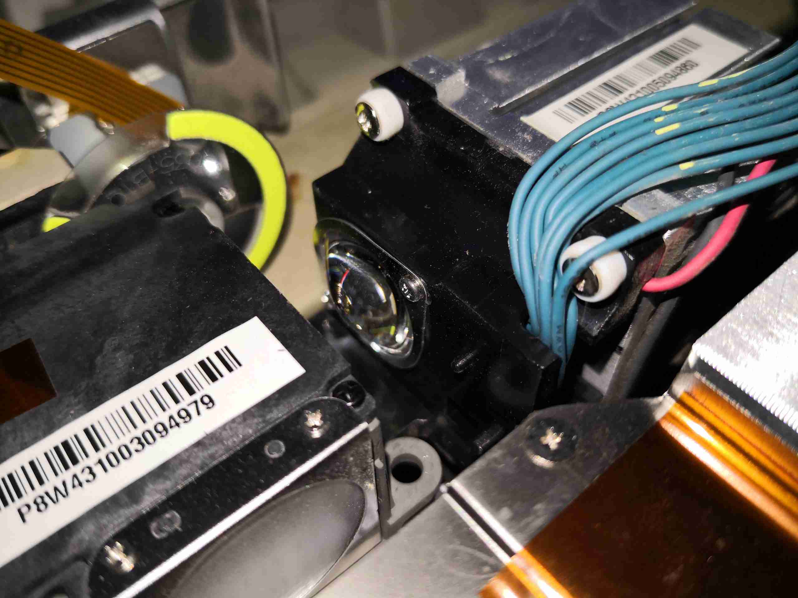
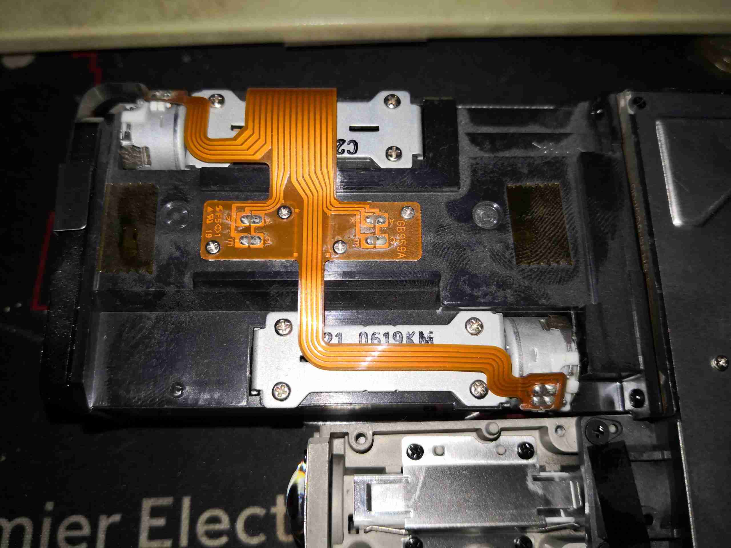
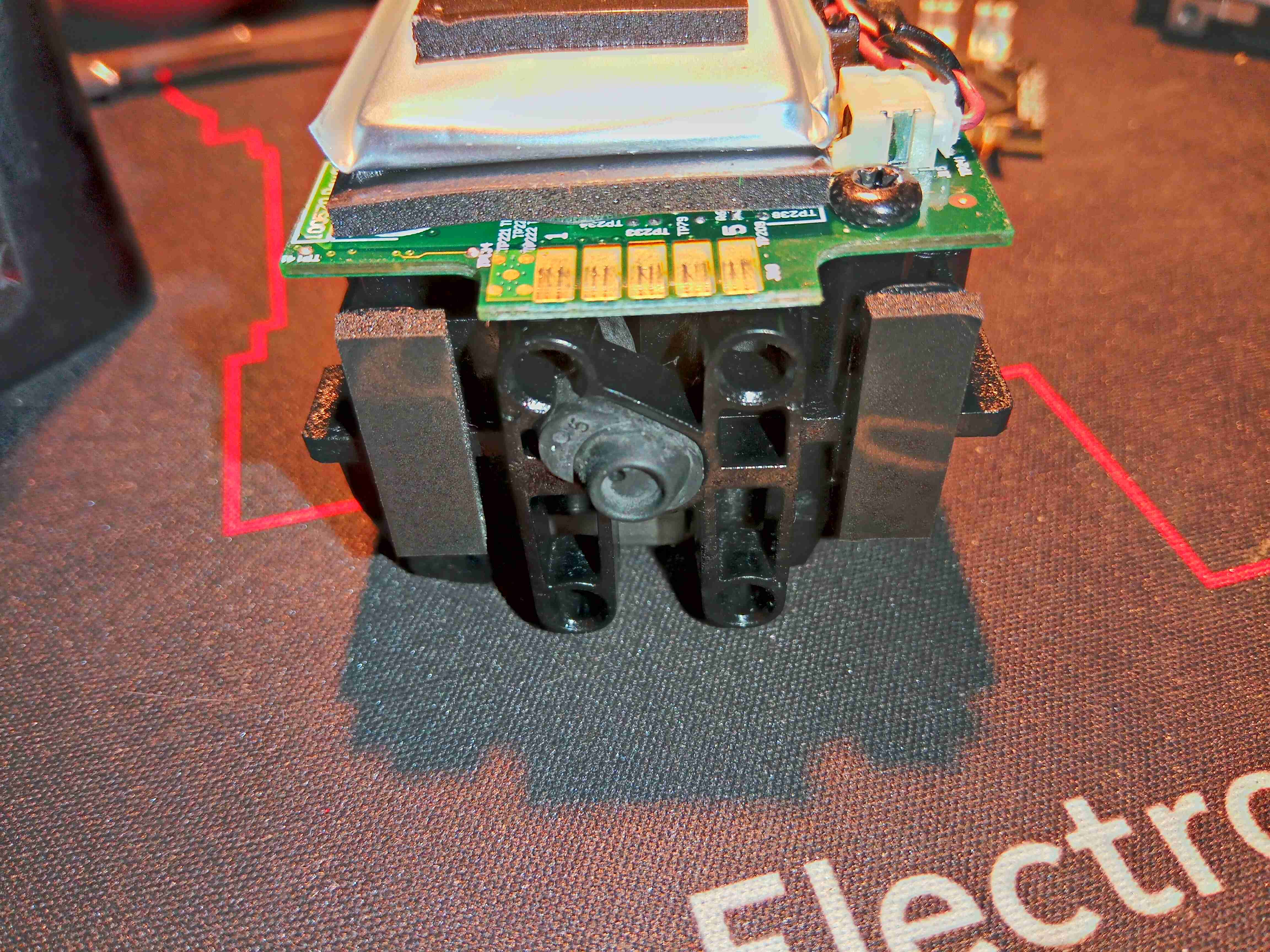
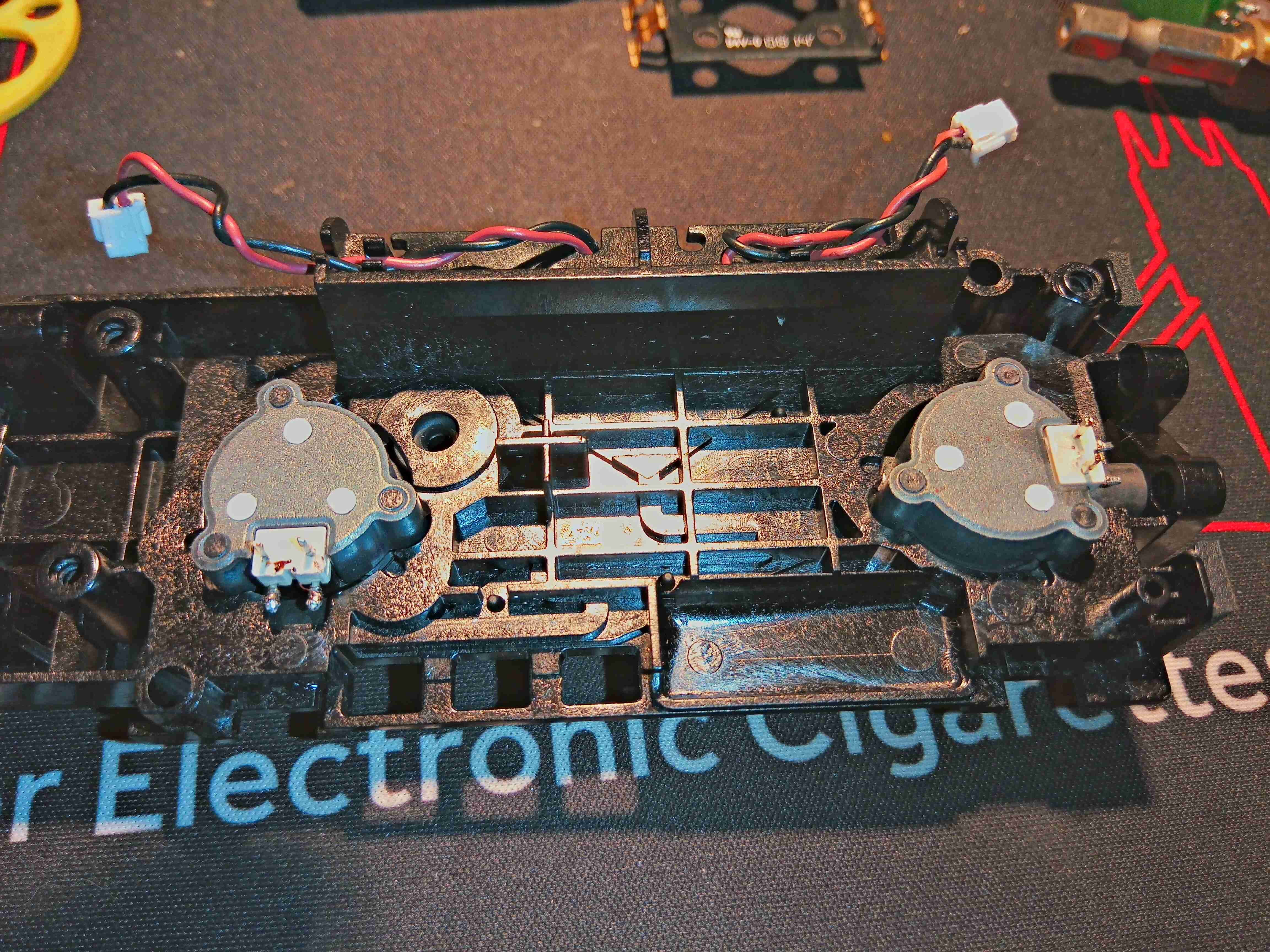
Focus & Zoom Motors
Underneath the objective lens are the pair of stepper motors that drive the focus & zoom mechanisms, along with their position sensors.
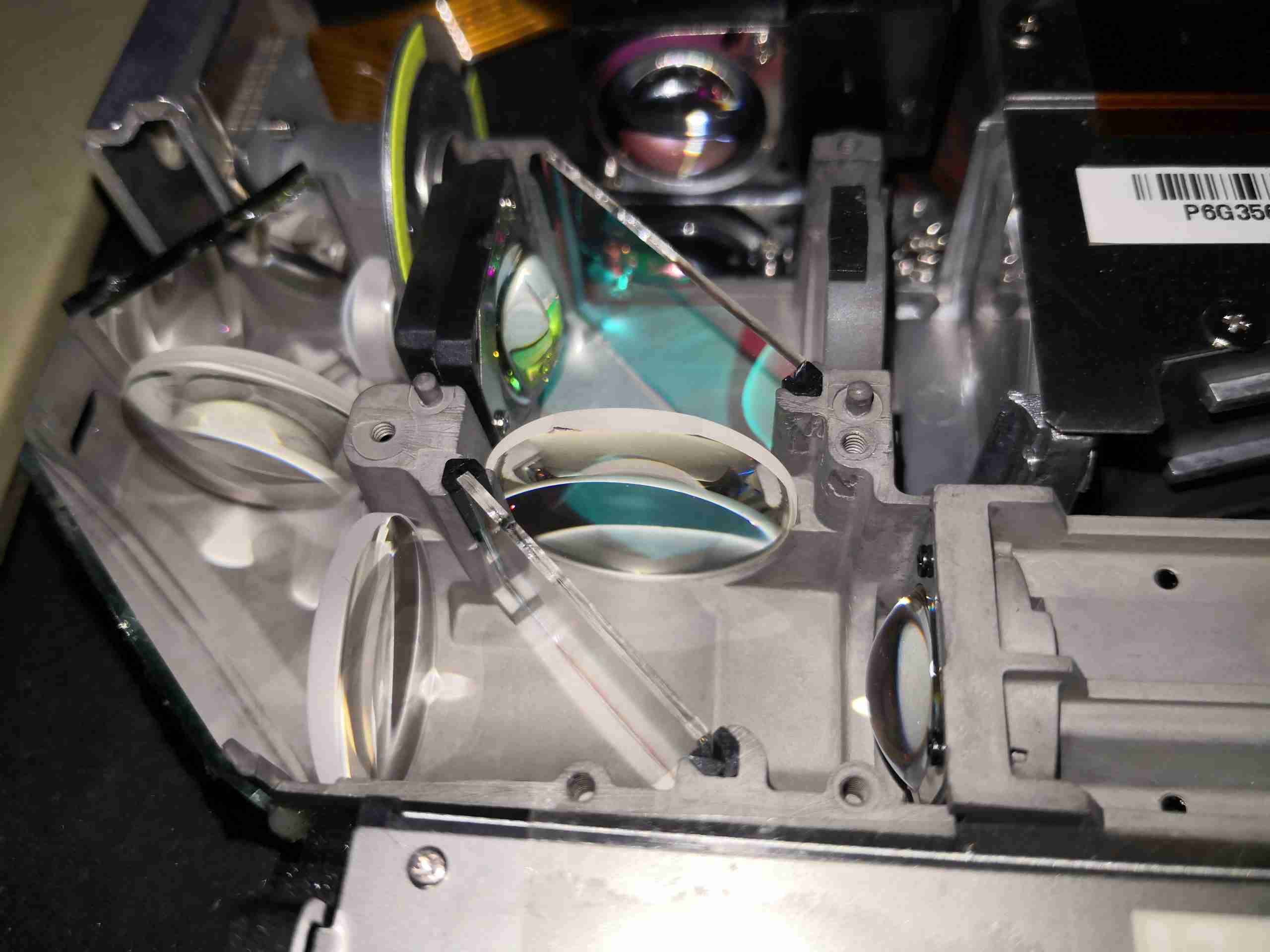
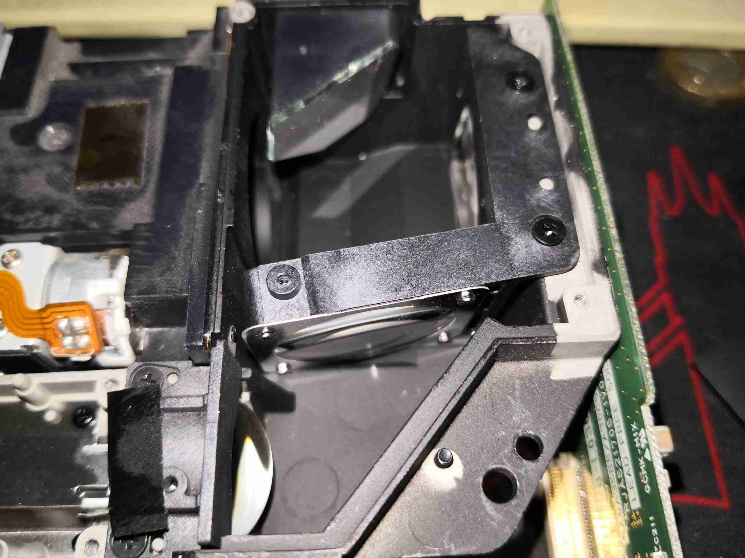
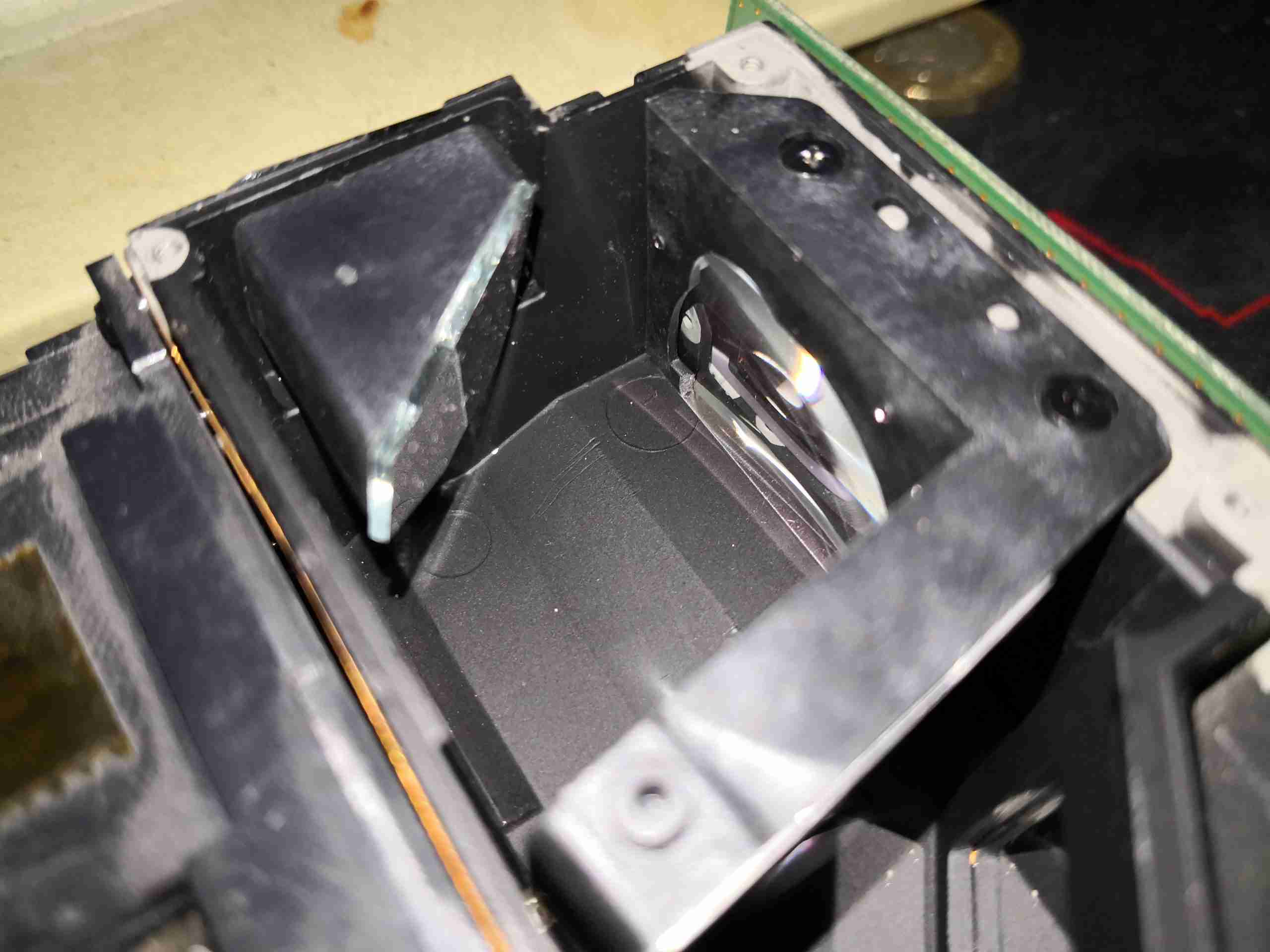
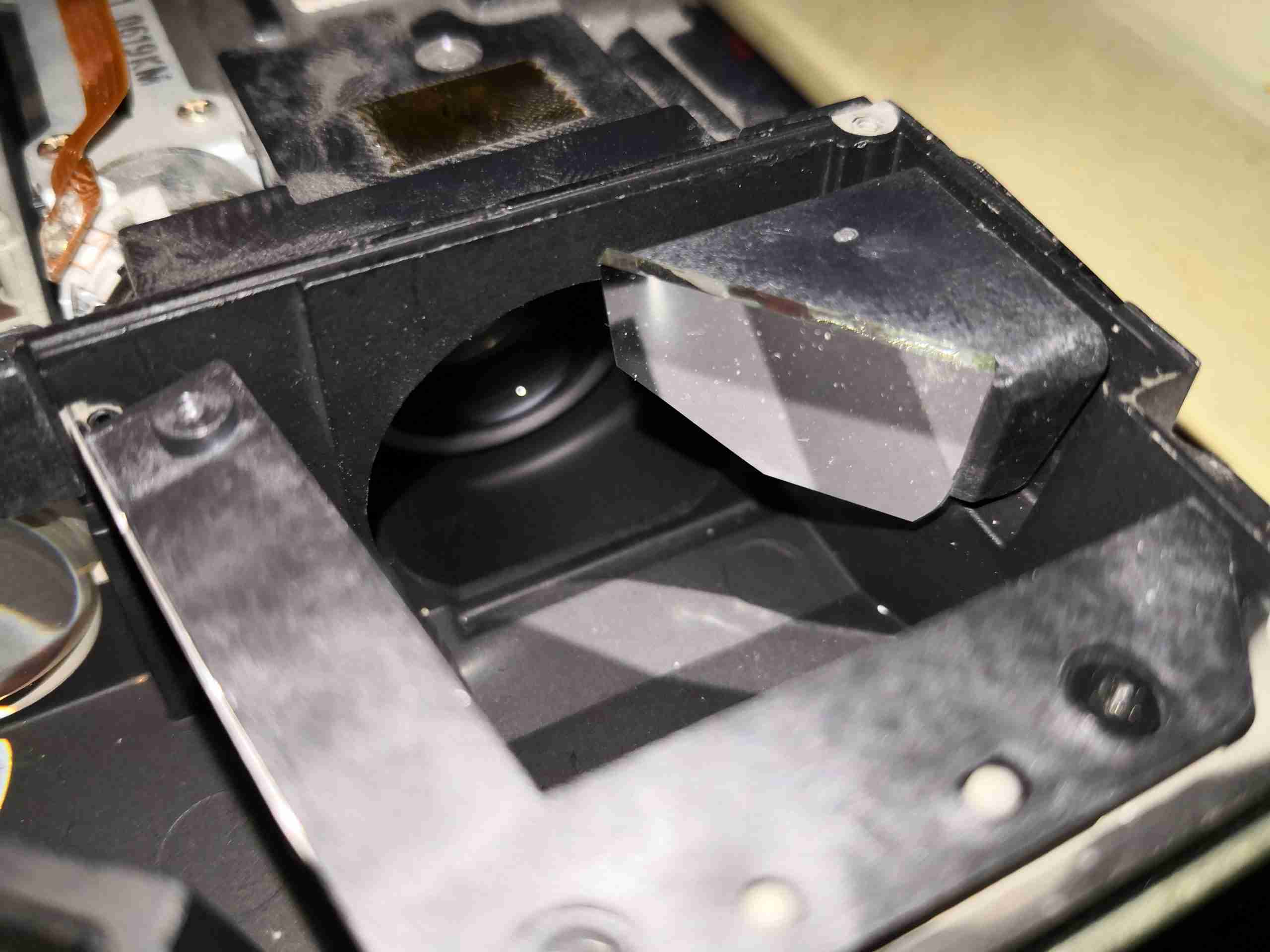
Turning Mirror
Just after the homogeniser, is the final optical path to the DLP. Here the light comes in a bottom left, and hits the turning mirror, after which it is focused onto the DLP chip by the mirror top centre. The objective lens is through the hole in the centre of the optical block, while the DLP is on the right side.
DLP Final Optics
Here’s where the DLP will be mounted in normal operation, with it’s lens in place.
Objective Lens
Finally, the created image is passed out through the objective lens to the projection screen.
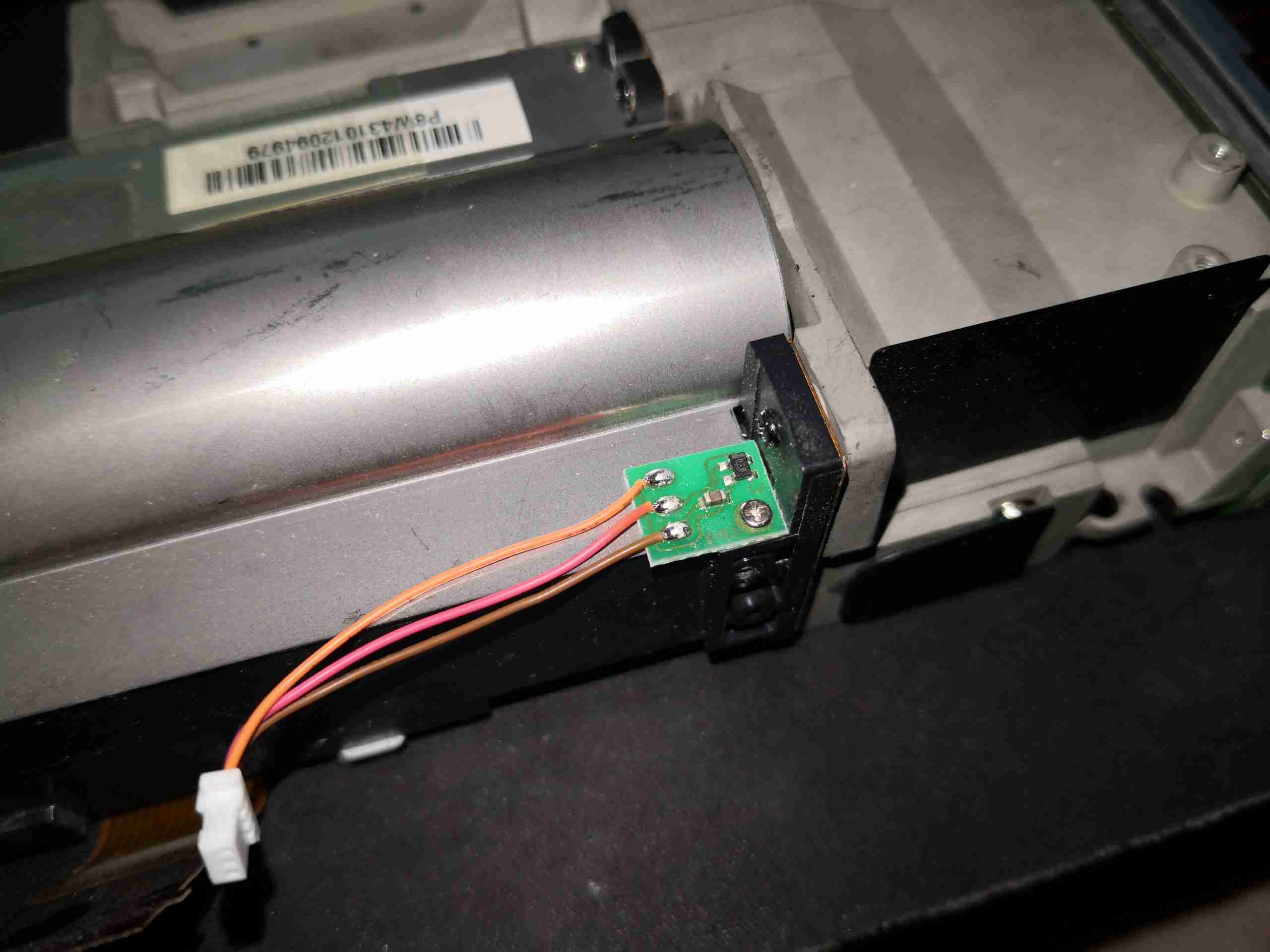
Hall Effect Sensor
There’s a sensor mounted on the side of the lens barrel, that I think is a Hall effect device, but I’m unsure what this would be used for, as there is no magnet anywhere near this to sense. It could also be a temperature sensor though, for the DLP & lens assembly.
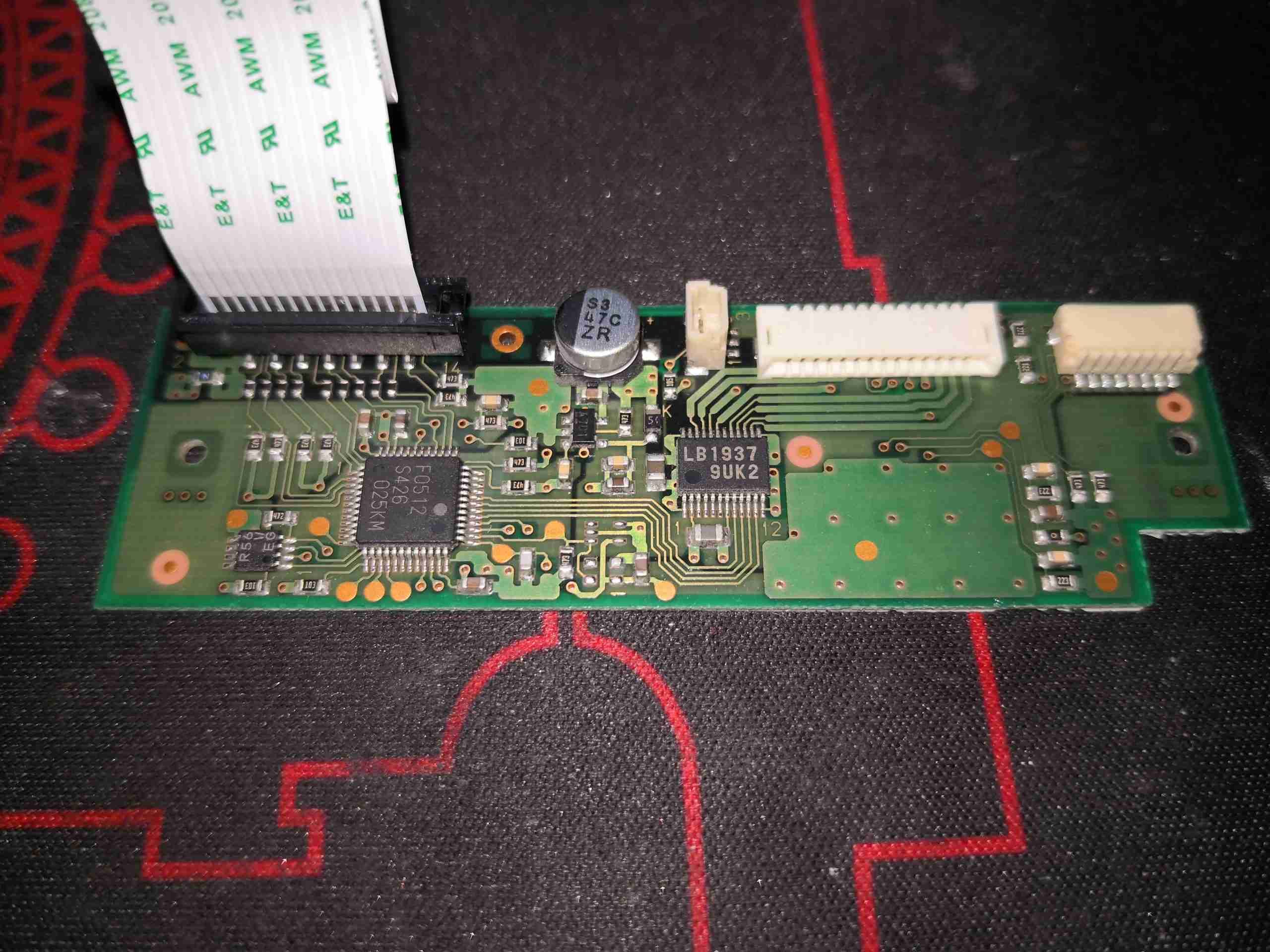
Stepper Motor Drive
The small PCB on the side of the lens unit holds the stepper motor drive IC, an LB1937 from Sanyo. There is another IC here, which looks to be a microcontroller.
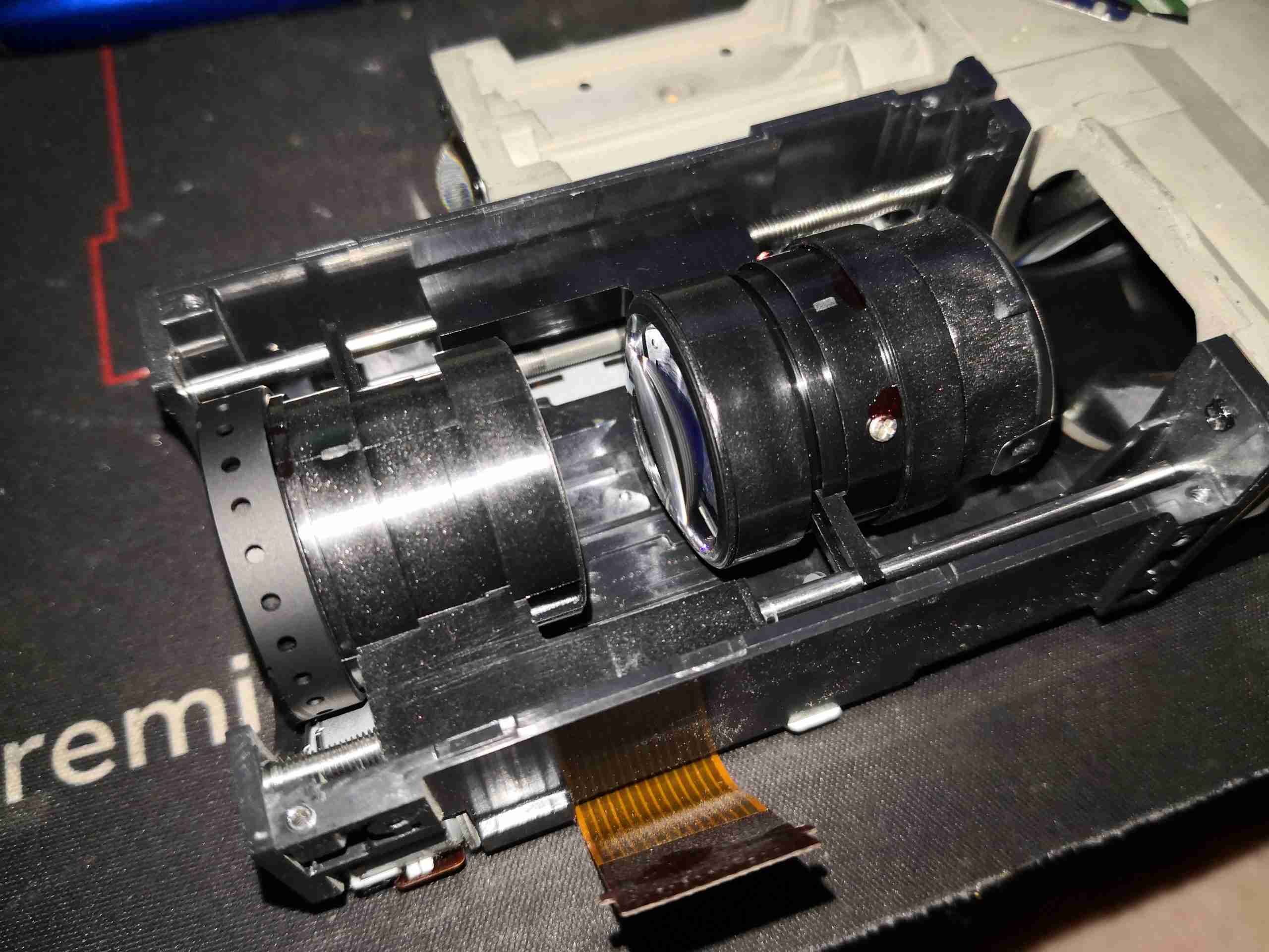
Lens Assembly
Removing the top cover allows the moving lens assemblies to be seen. These move independently of each other to implement focus & zoom, via lead screw drives on the stepper motors.
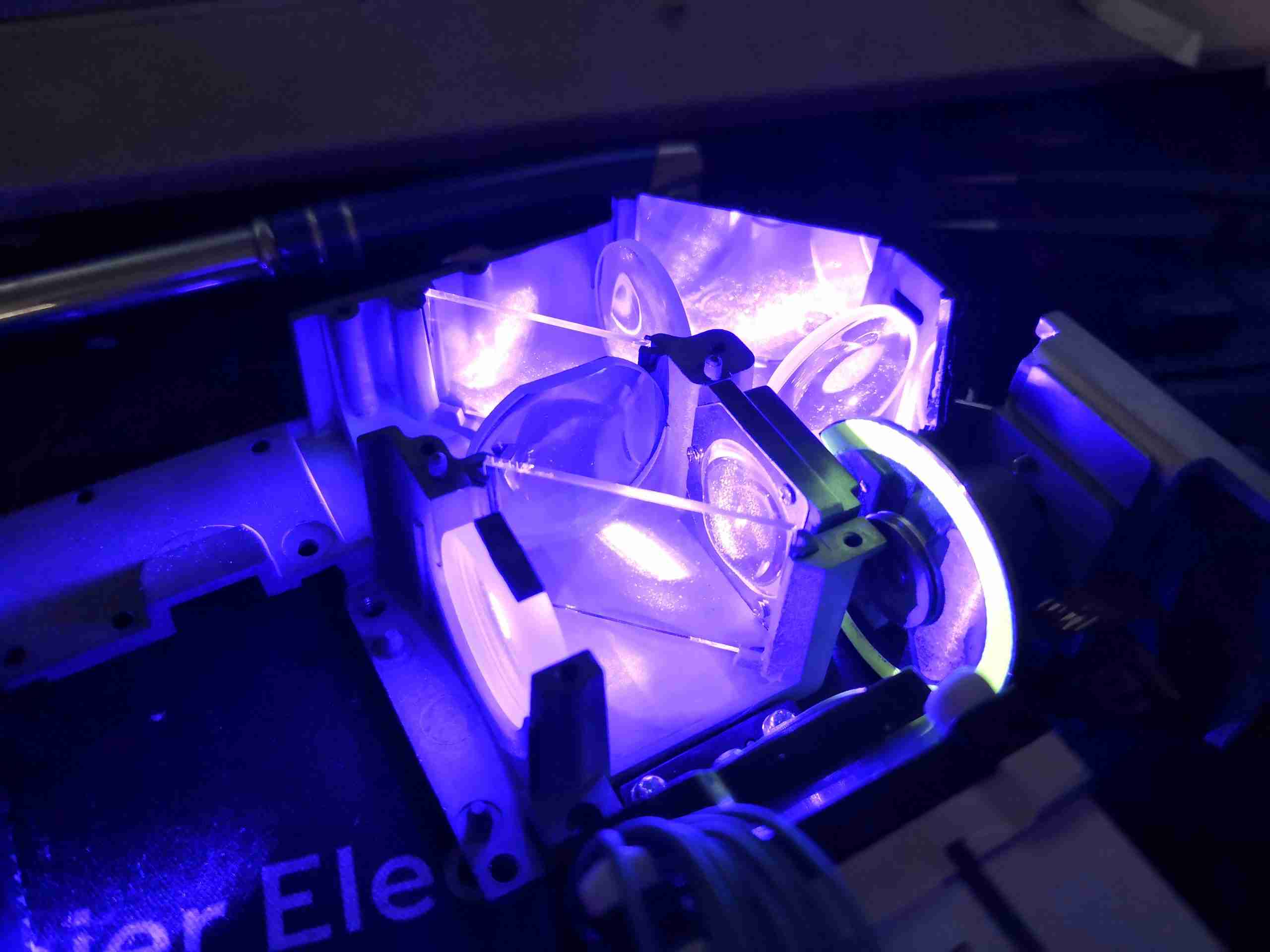
Blue Light Path
Here I’m shining a separate 445nm diode laser into the optical assembly, through the blue optical path. The phosphor wheel is turned to the clear section, which allows the 445nm light to pass straight through, being turned 180° by the mirrors & directed out towards where the DLP assembly would be.
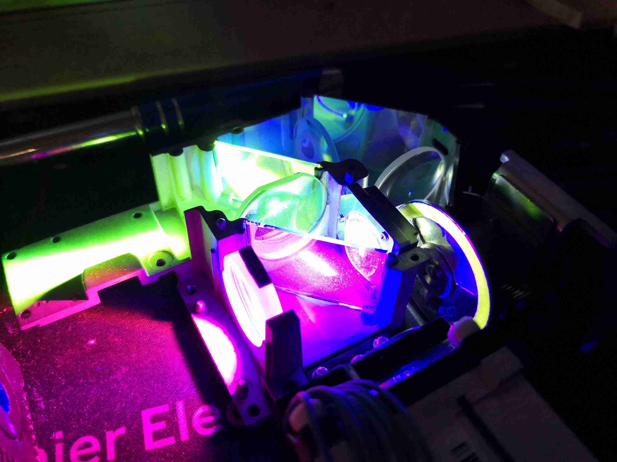
Green Light Path
Turning the phosphor into the light path causes a very bright green light to be generated, and passed back towards the 445nm laser entry point. The dichroic mirror in the way reflects this light to the left, through a lens & then to the other dichroic mirror to be turned another 90° to the DLP assembly. I’m not sure where the magenta light is coming from – the phosphor probably generates light on more wavelengths than just pur green, giving some red to mix with the blue.
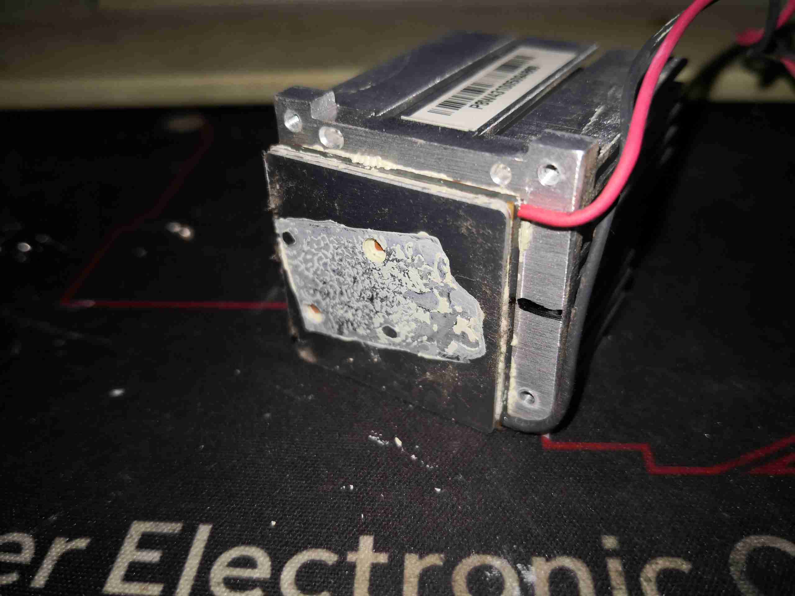
PhlatLight LED
Here’s the Red LED removed from it’s cooling & collimation assembly – this has an enormous silicon emitter area, and apparently these LEDs are designed to be uniform in light emission, specially made for projection use. There’s a thermistor onboard for temperature sensing – sensible when the datasheet gives CW currents of 8A, and pulsed currents of 13.5A!
LED TEC Cooler
Not surprisingly, cooling this beast of an LED requires more than just a heatsink, so it’s mounted on a TEC module, possibly around 40W thermal capacity.
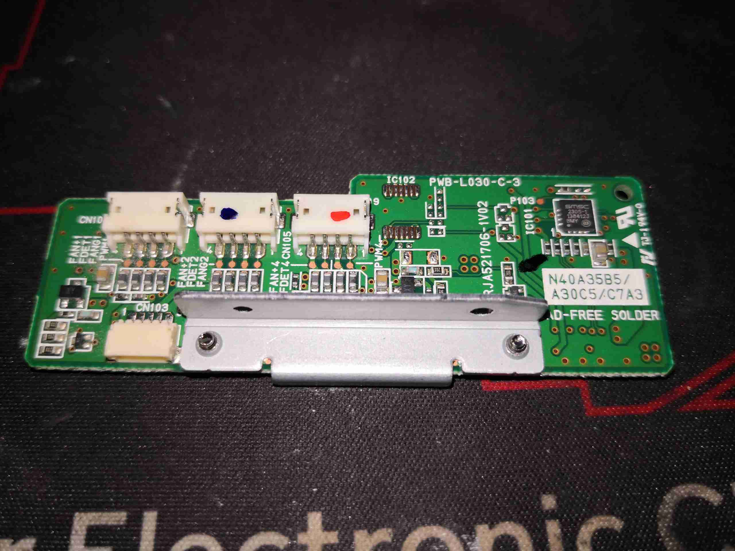
Fan Control Board
Fan control is handled by this little PCB, squeezed in between the optics engine & 445nm Laser array. There’s a SMSC EMC2305 I²C 5-channel PWM fan controller on here, communicating back to the main system microcontroller. Besides some passives, and 4 transistors to make sure the fans don’t start at full power when the projector is powered on, there’s not much else.
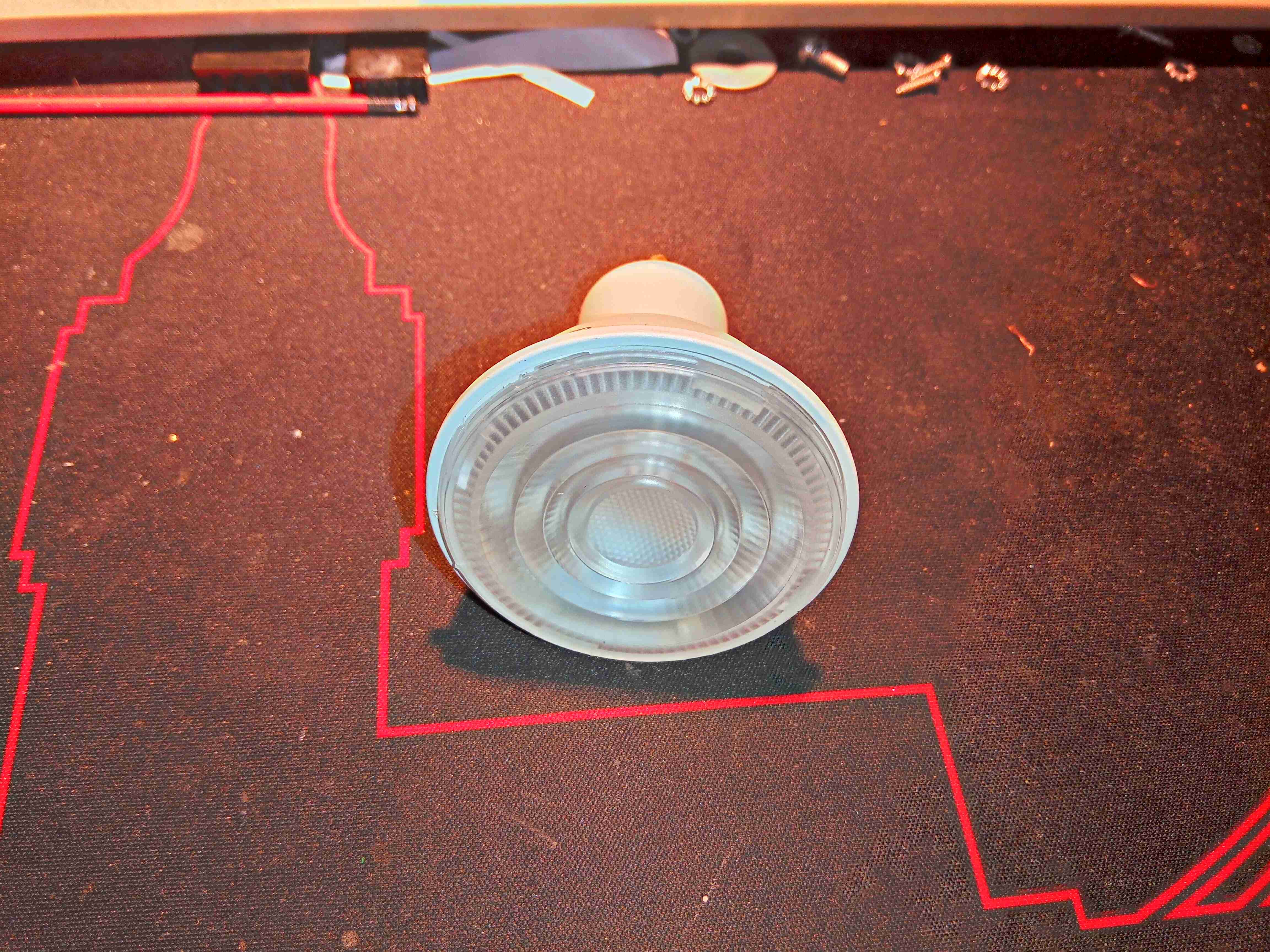
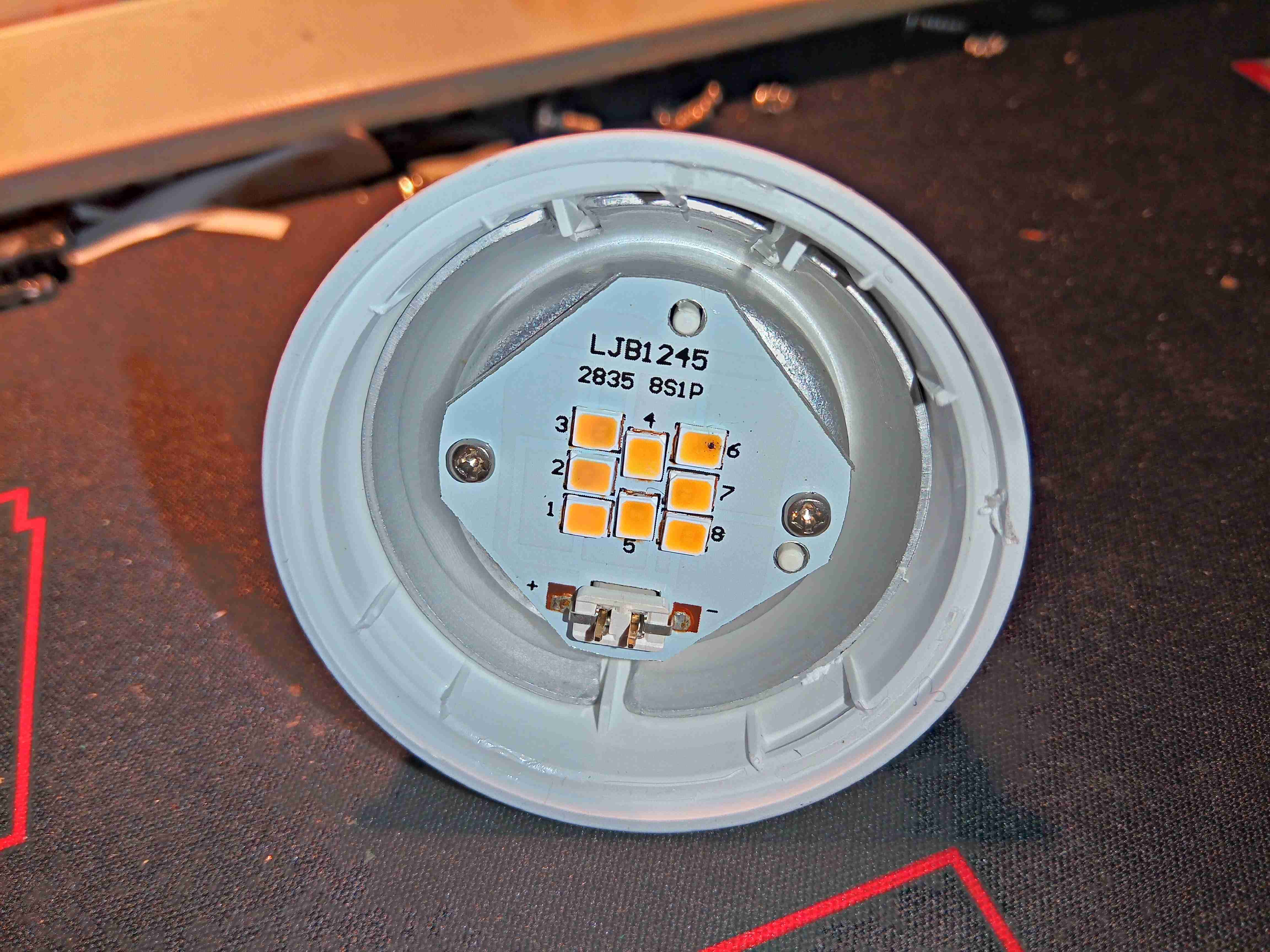
Here’s a recently failed 5W GU10 lamp, which is completely dead – not even a single LED still shining.
Markings
According to the markings, this lamp draws 50mA at 230v & outputs 345 lumens
Lens Removed
After popping the lens off the body, the failure mode is obvious. The top right LED has the Black Spot Of Death, where one of the LED dies has catastrophically failed in service. As these lamps usually have all the multi-die LEDs in series, a single failure will cause the lamp to totally fail. Running LEDs hard, with little cooling is a common cause of this kind of failure. There isn’t much in the way of heatsinking in this lamp, as the outer casing is plastic, and even though the LEDs are soldered to an aluminium cored PCB, the only other heatsink is the aluminium base for the PCB, which is in contact with the outer plastic.
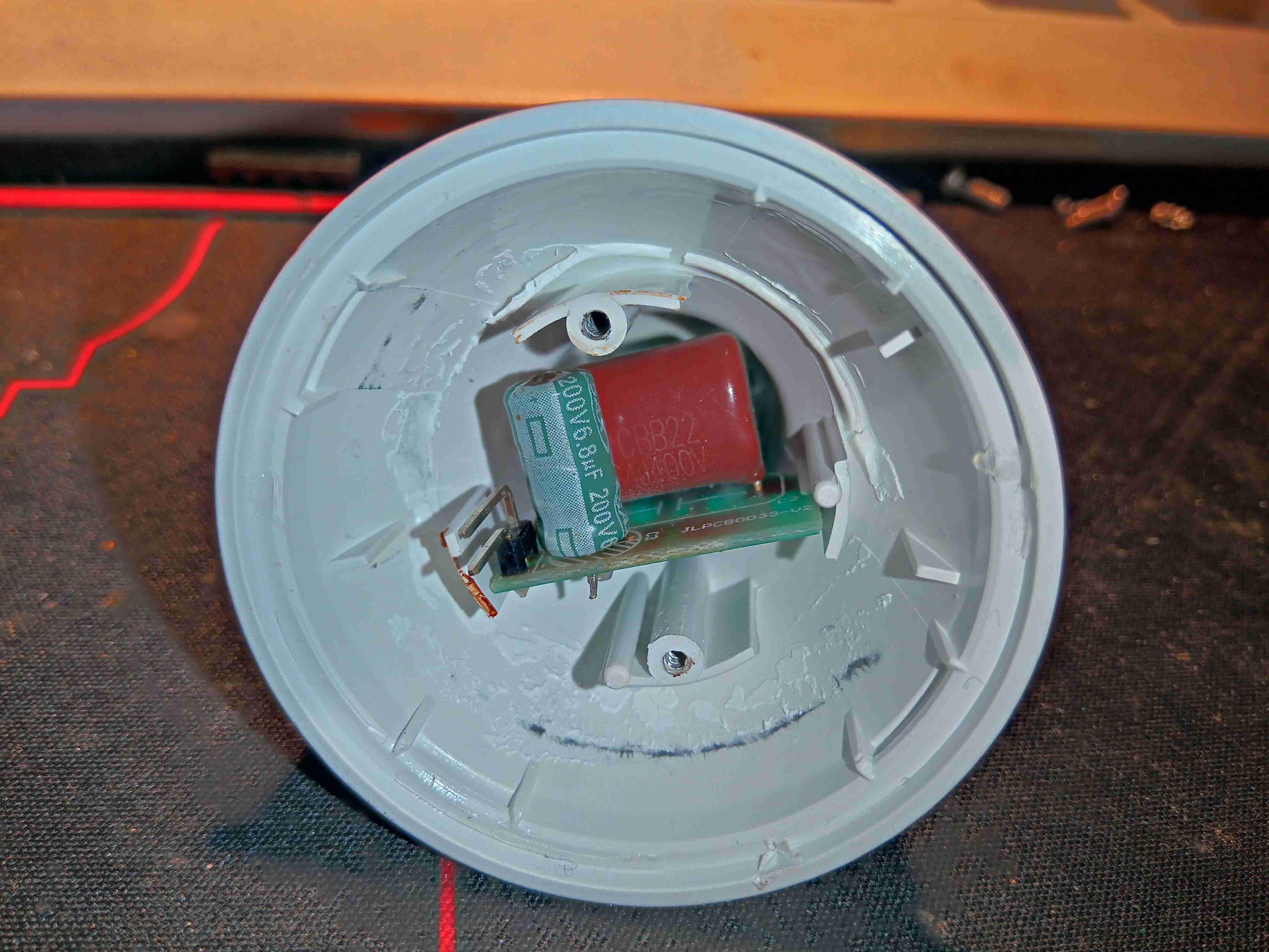
PSU
Removing the LED board & backing plate allows access to the power supply in the rear of the lamp. There’s no switching supply in this one, just a large film capacitor.
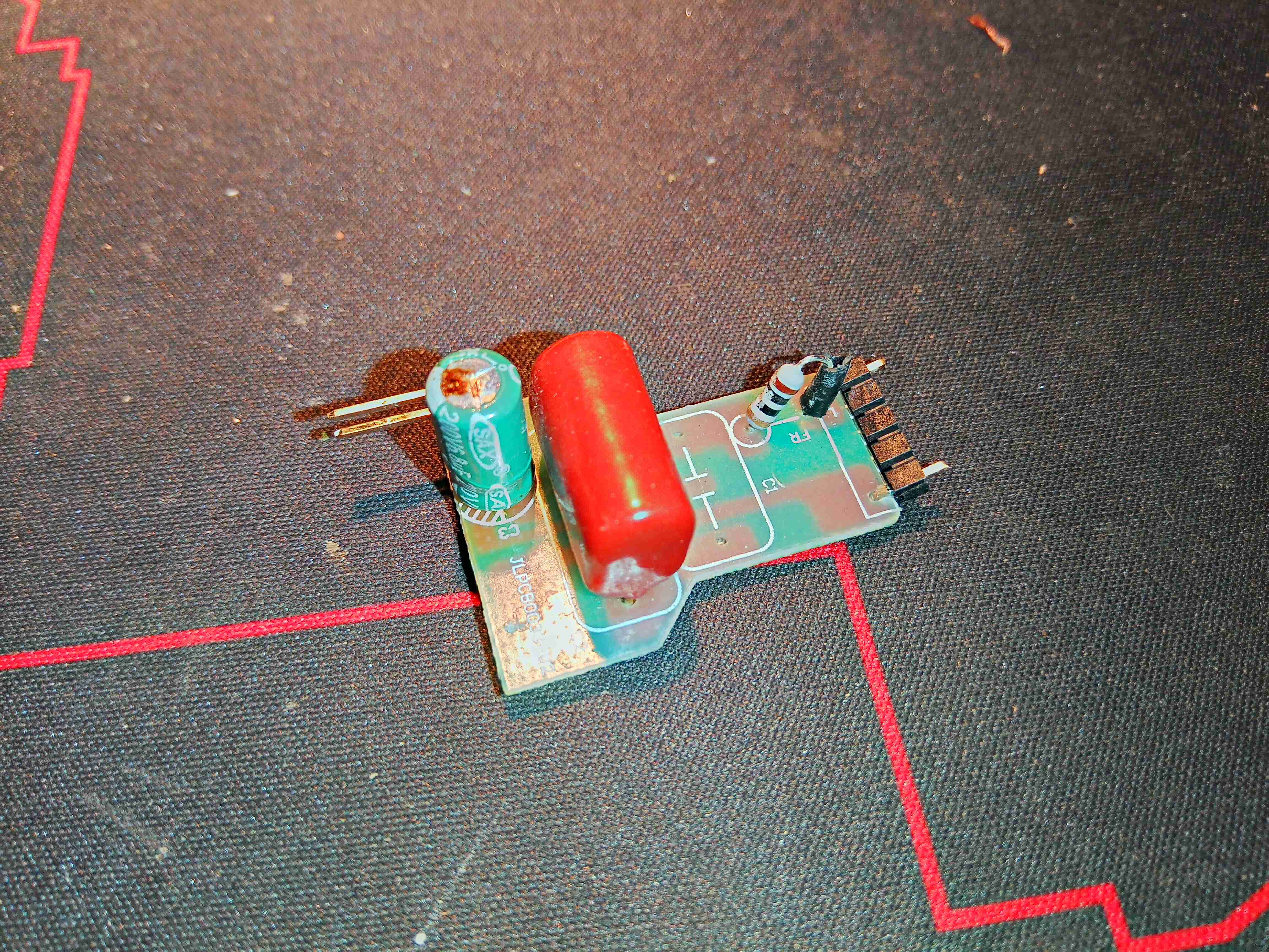
Capacitive Dropper
Snipping the pins off the back allows the PCB to be removed, exposing the capacitive dropper from the mains. The output electrolytic cap has also failed on this board, as can be seen from the opened vent on the top.
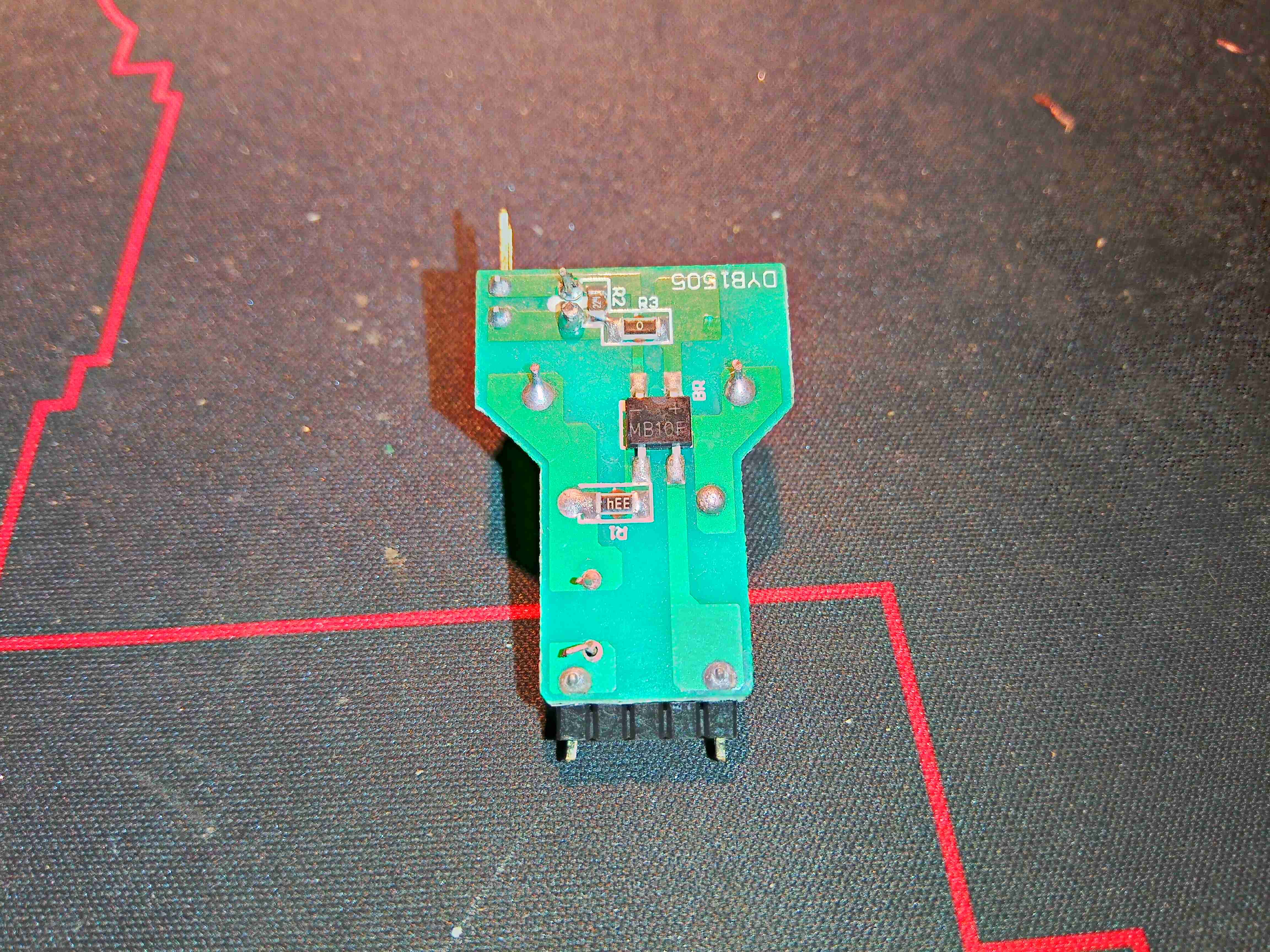
PCB Reverse
There isn’t much on the back side of the board, apart from the bridge rectifier & a couple of resistors.
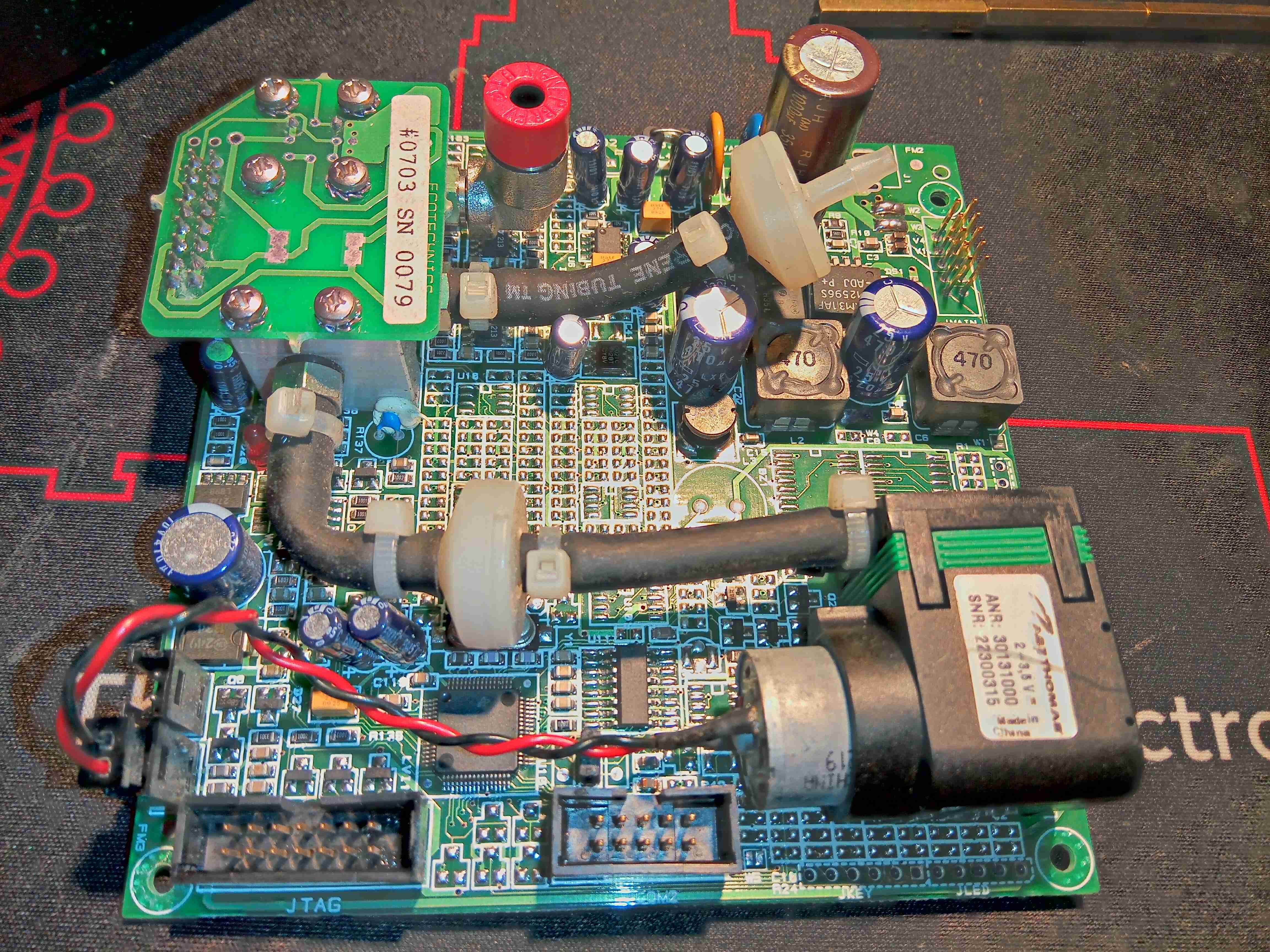
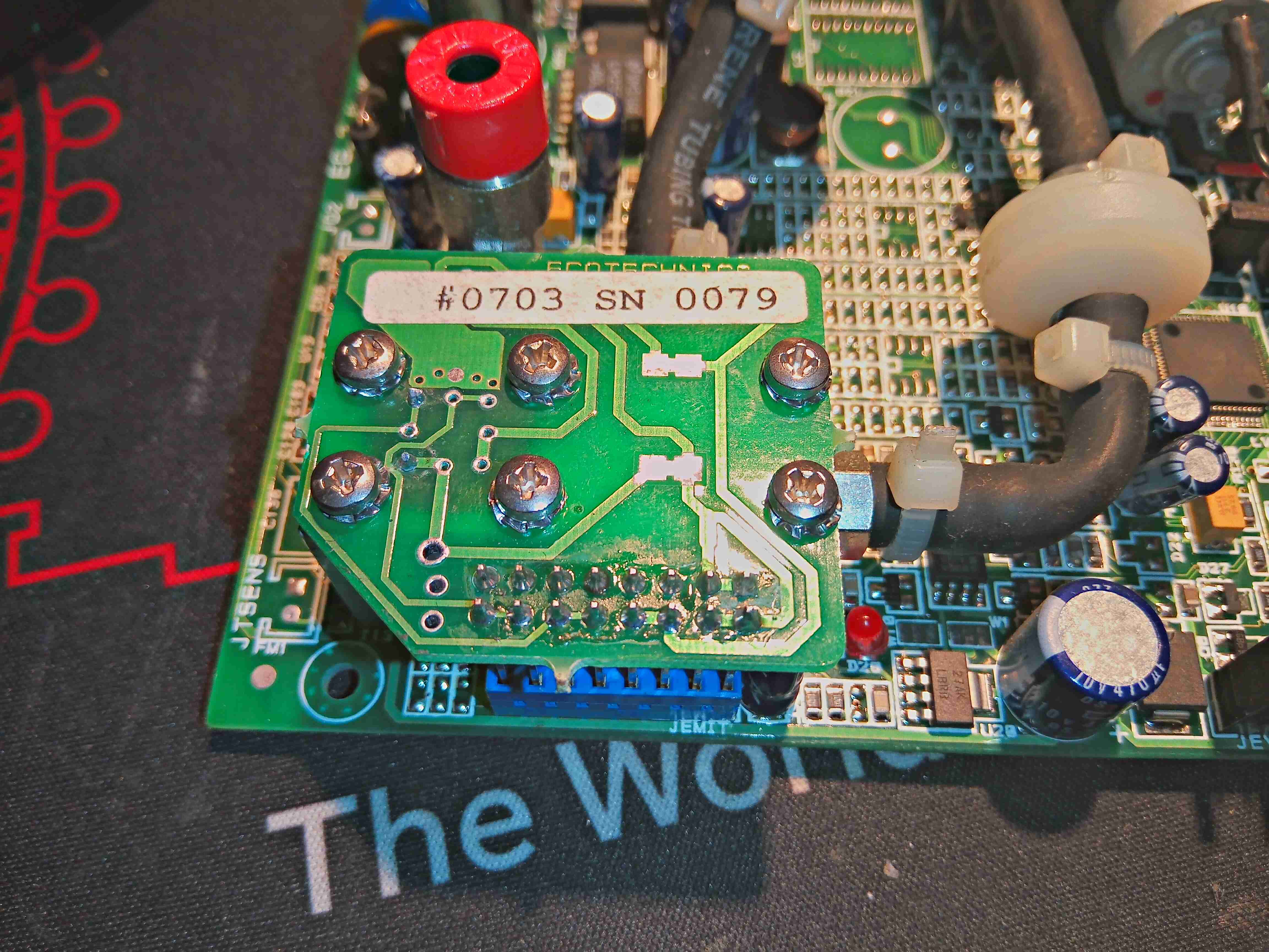
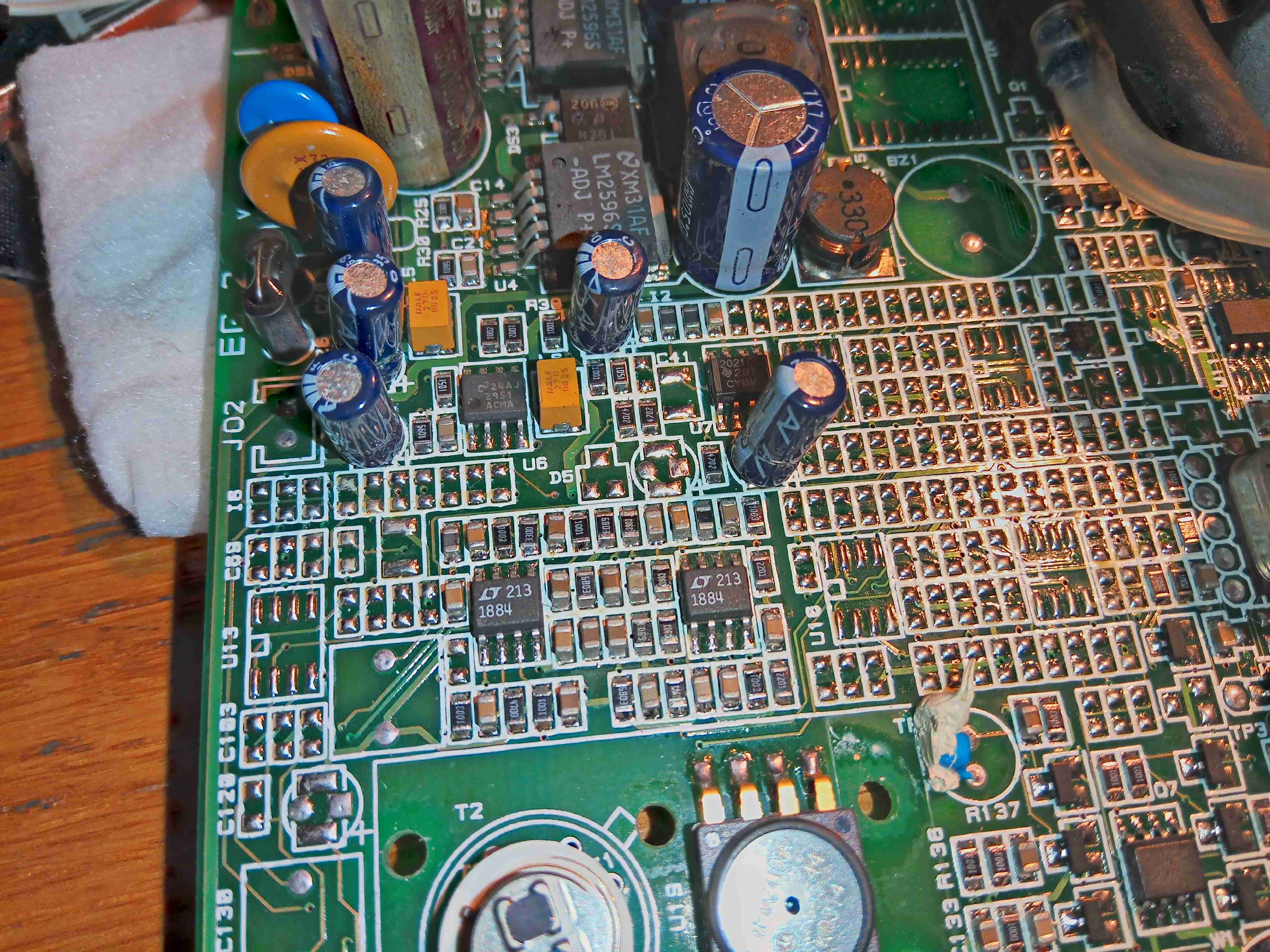
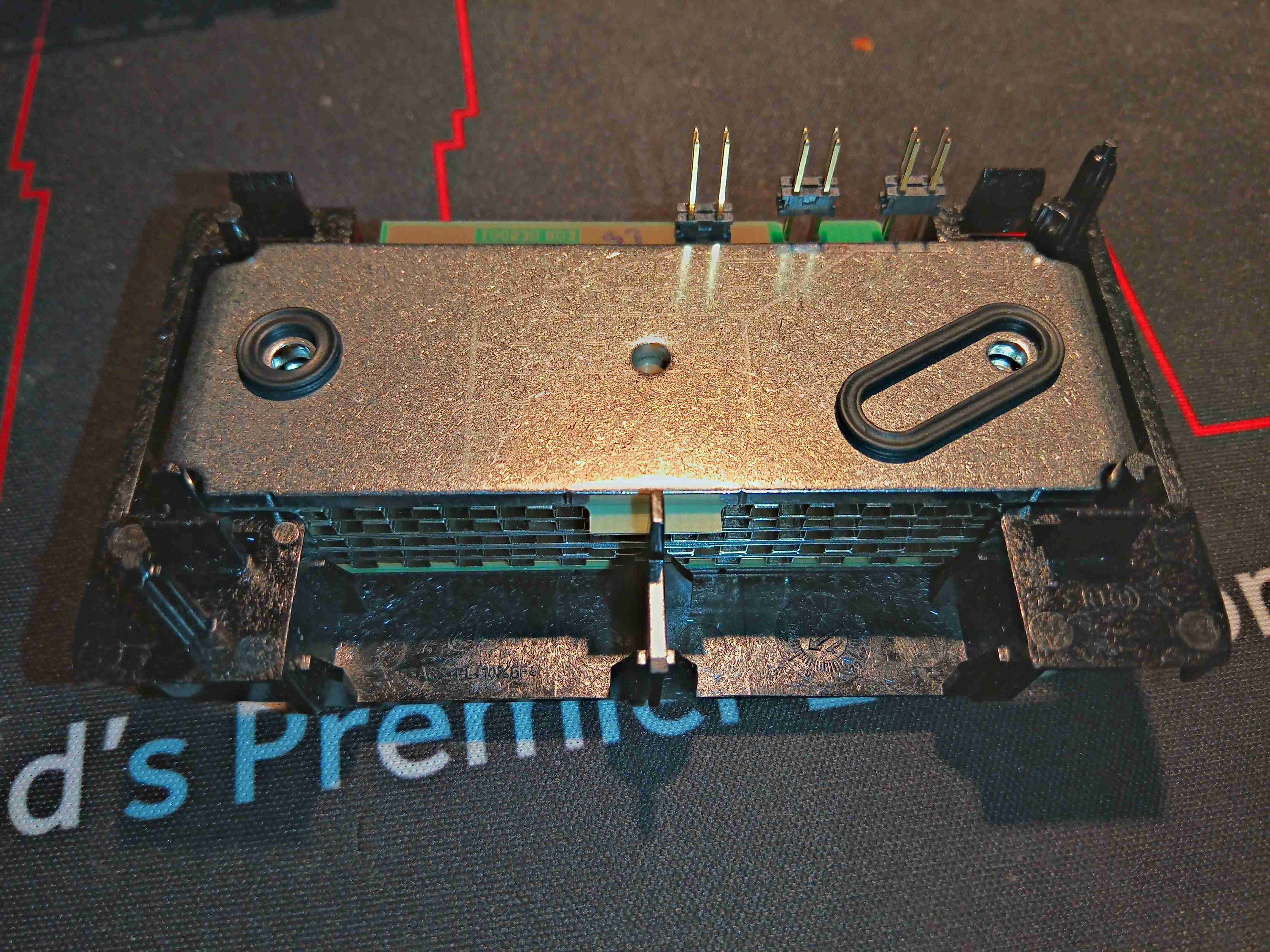
This unit recently appeared on eBay, as a spare part from a refrigerant charging machine, and I figured it would make a good explorational post. This unit analyses the purity of R-134a refrigerant gas, using an Infrared sensor cell, and communicates over RS-232.
The sensor cell itself is at the top right of the board, we’ll get to that later on. There’s a small diaphragm pump at the lower right, for purging the cell with air. The port with the red cap is the outlet, and the remaining open hose barb is the input of gas to be tested. This would connect to a flow regulator & solenoid valve that the board controls.
It’s pretty clear that this board has multiple applications from all the unpopulated components. There’s space for a keypad, indicator LEDs & an LCD on board, so maybe this can also be fitted to a handheld analyser?
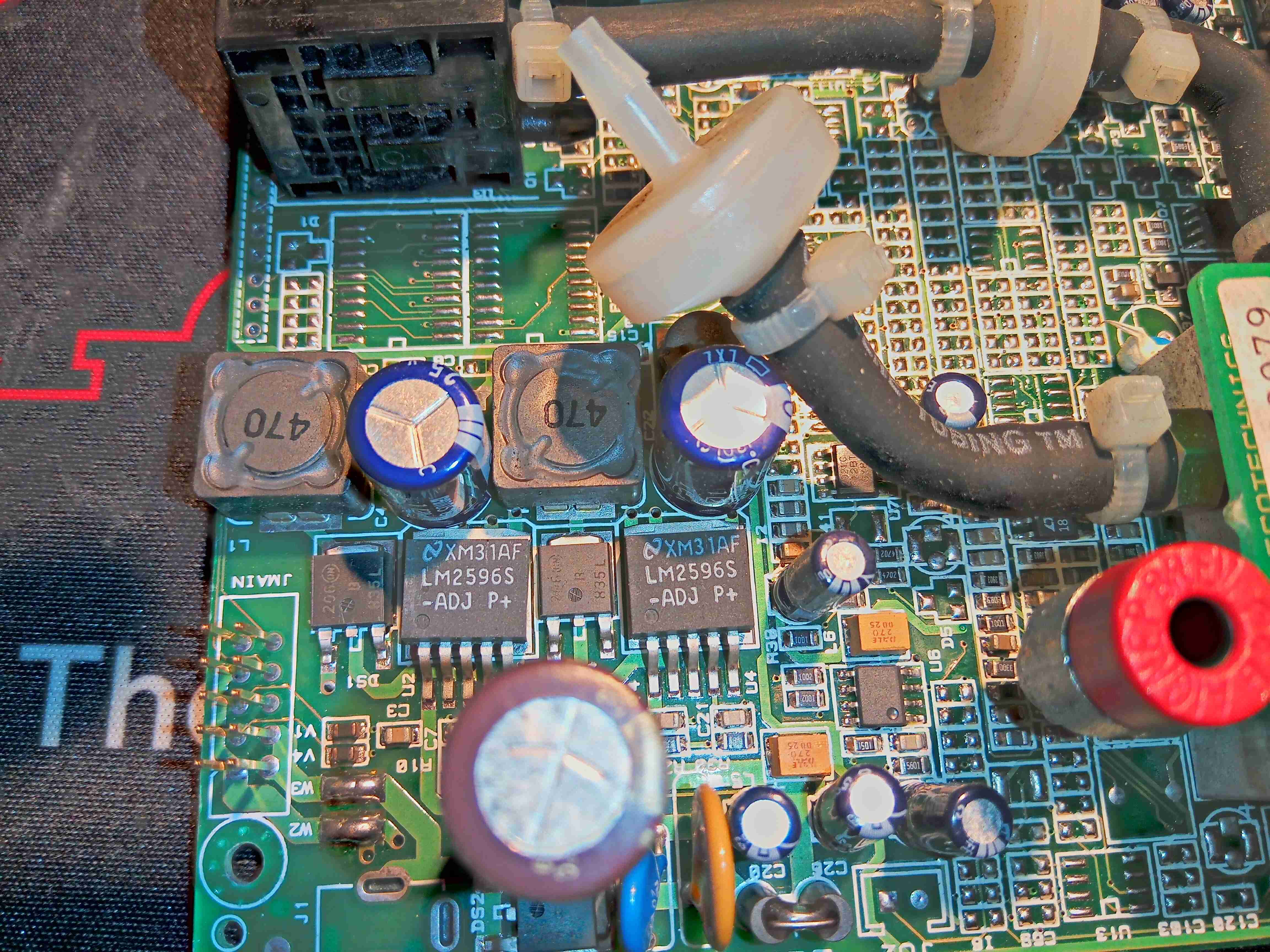
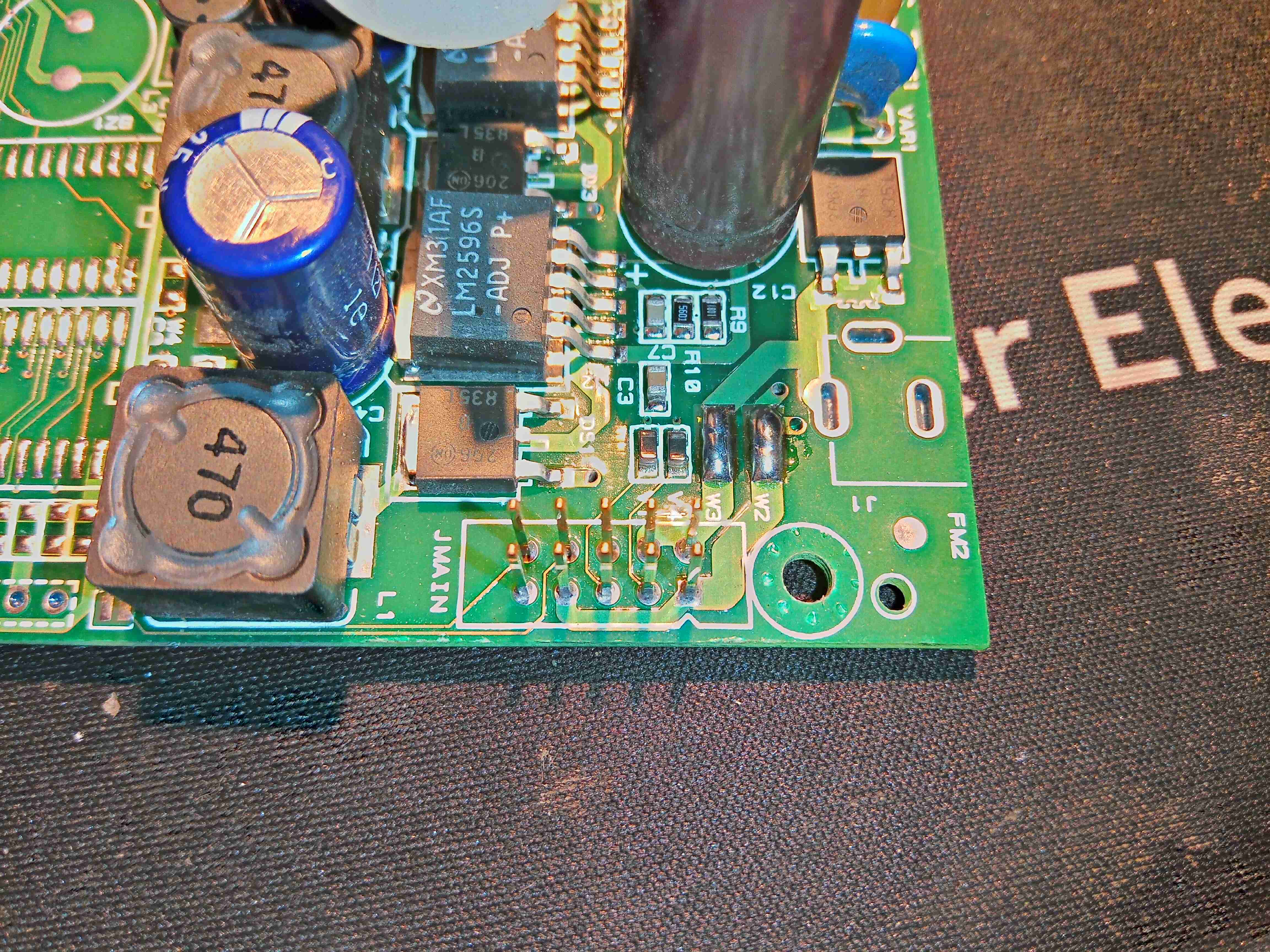
Power Supply
From looking at the input circuitry, I can surmise that the input voltage is somewhere between 12-24v DC, as there is a 35v input electrolytic filter capacitor. There’s a couple of switching regulators which generate 5v & 3.3v rails for the board, with some input fusing.
Main Connector
There’s two serial links on this board, driven from the main microcontroller – the primary one is on the connector marked JMAIN, along with the power input & a couple of other unknown signals.
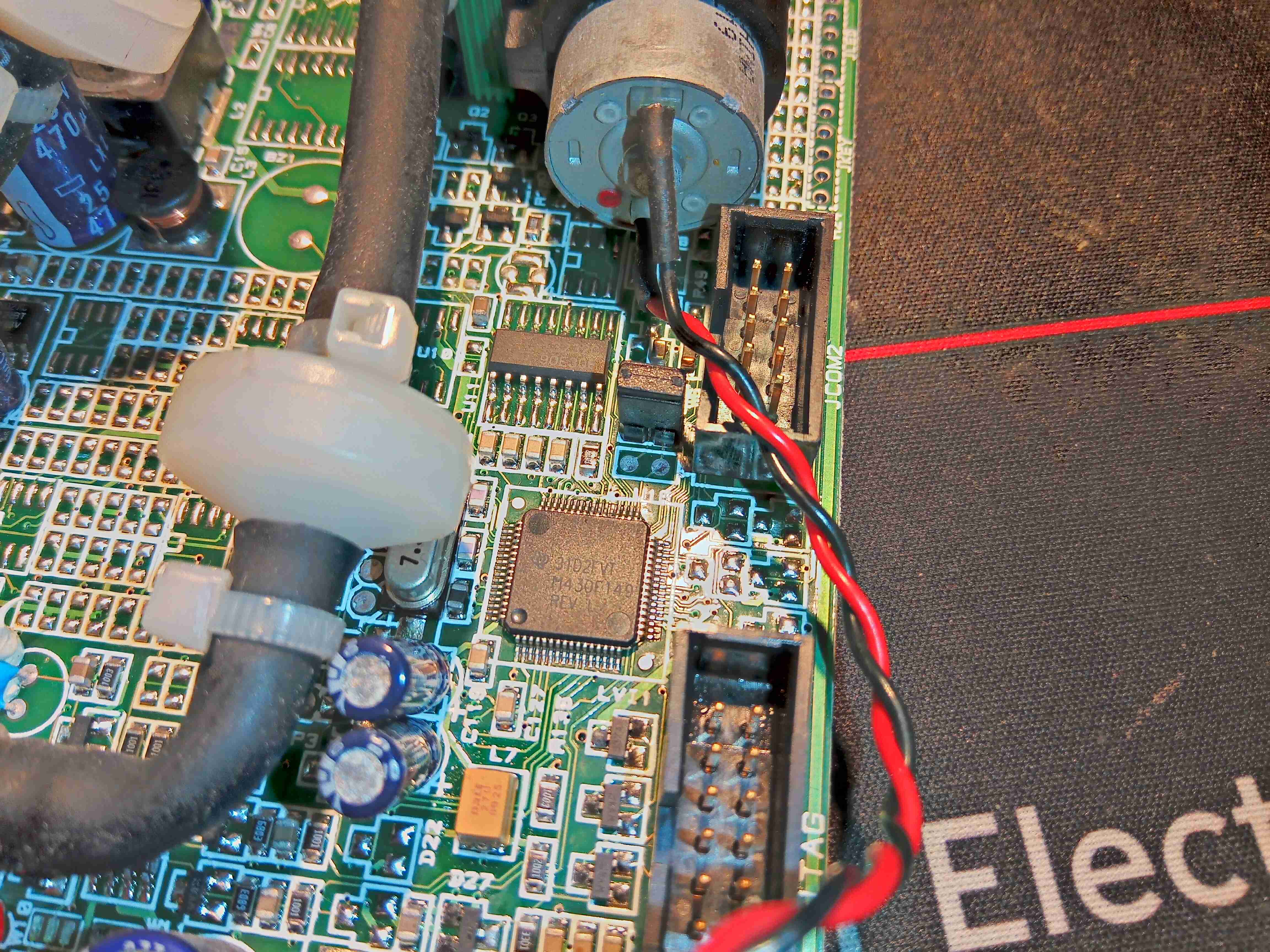
MSP430 Microcontroller
Over on the other side of the board is the brains of the operation – an MSP430 microcontroller, with an RS232 transceiver IC & another RS-232 port marked COM2. The remaining connector is a JTAG port for the micro.
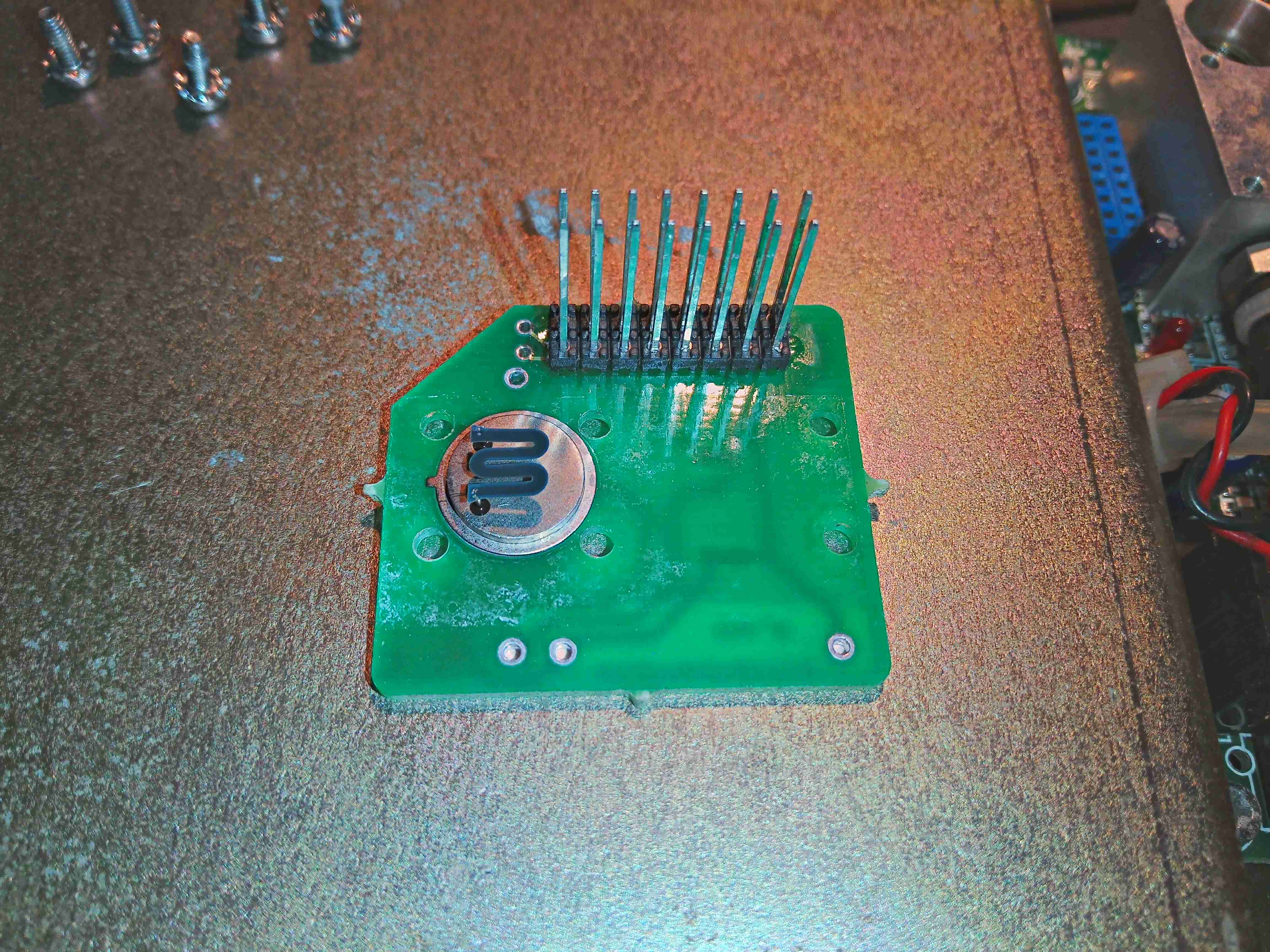
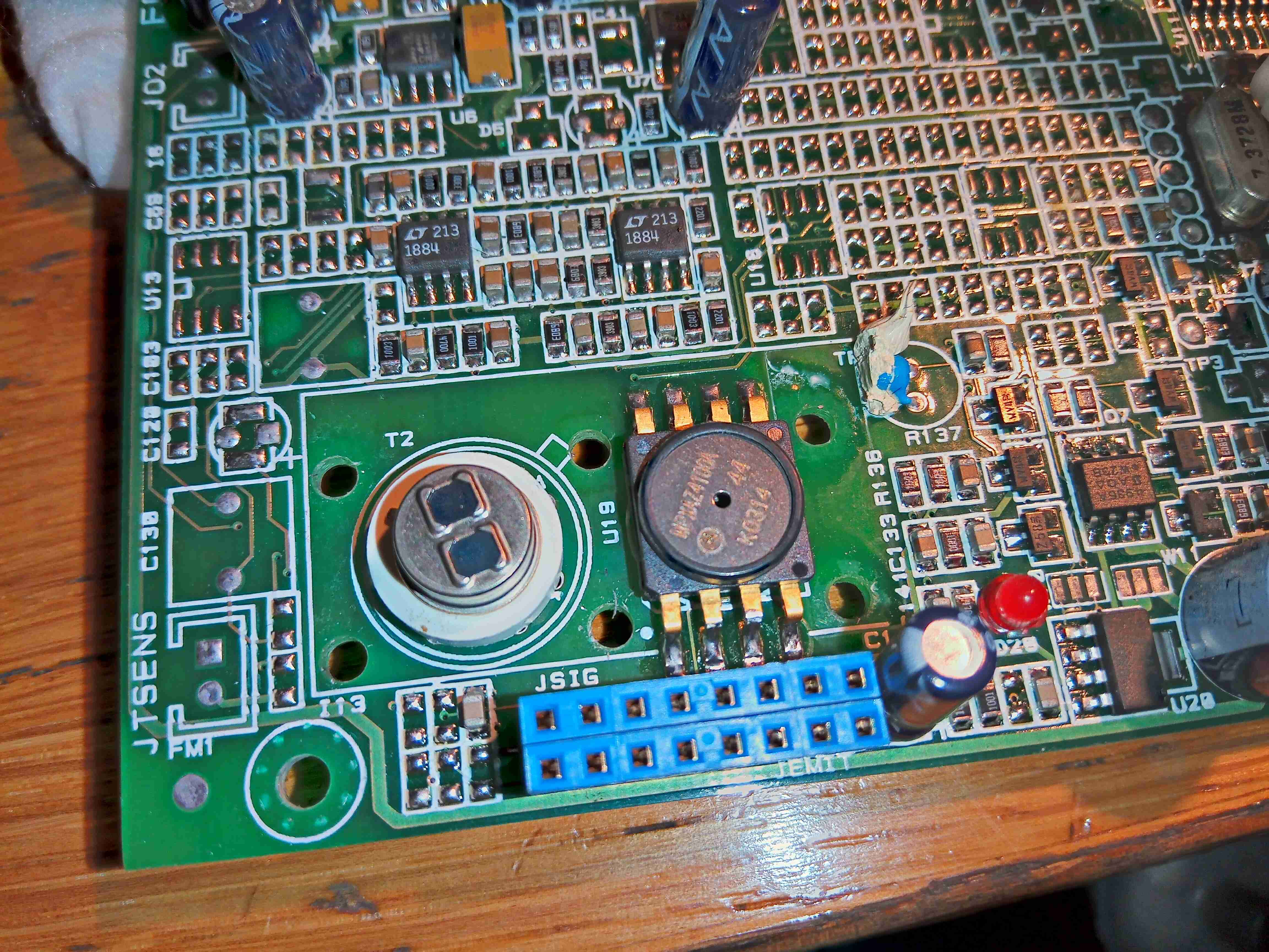
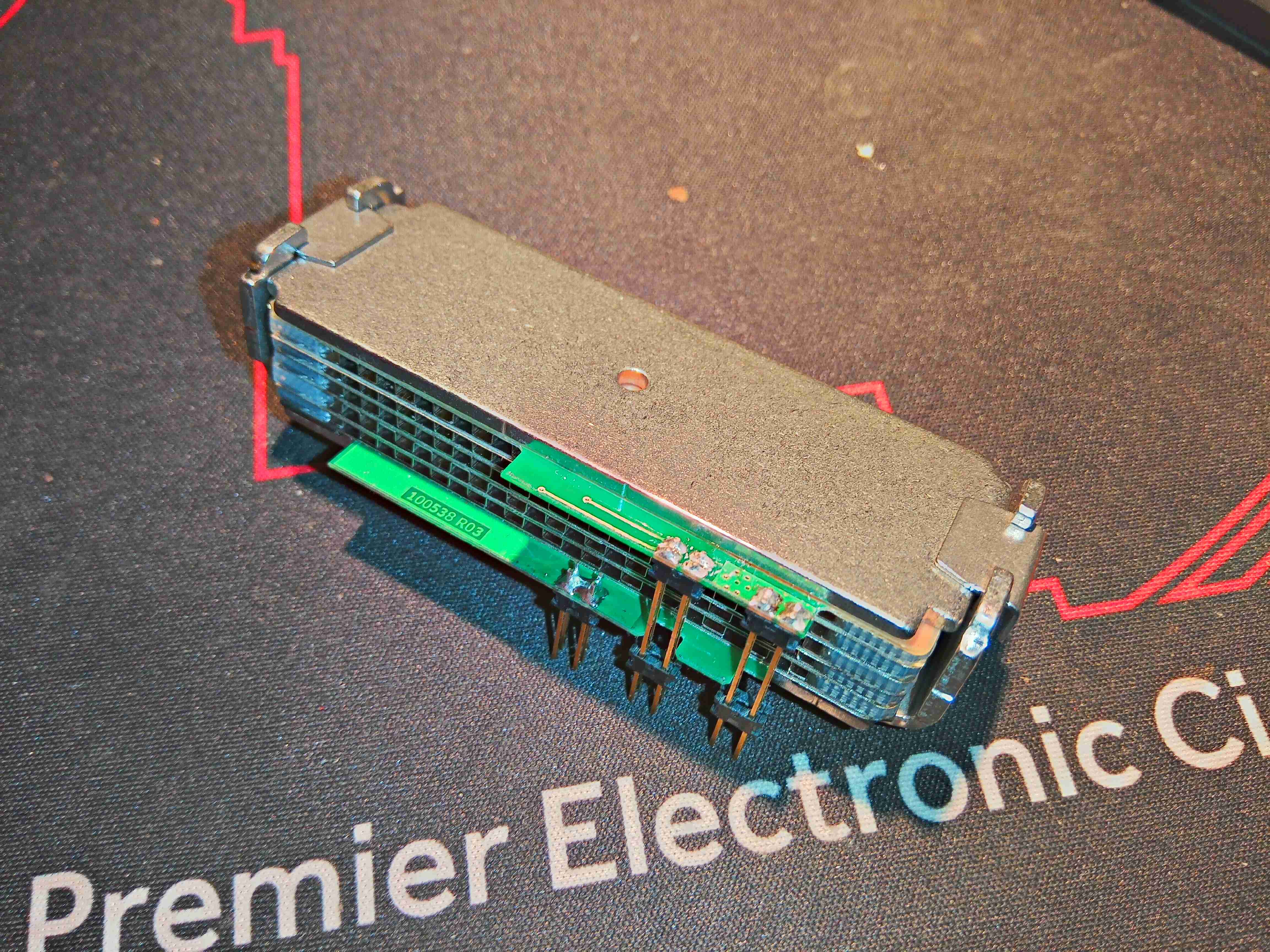
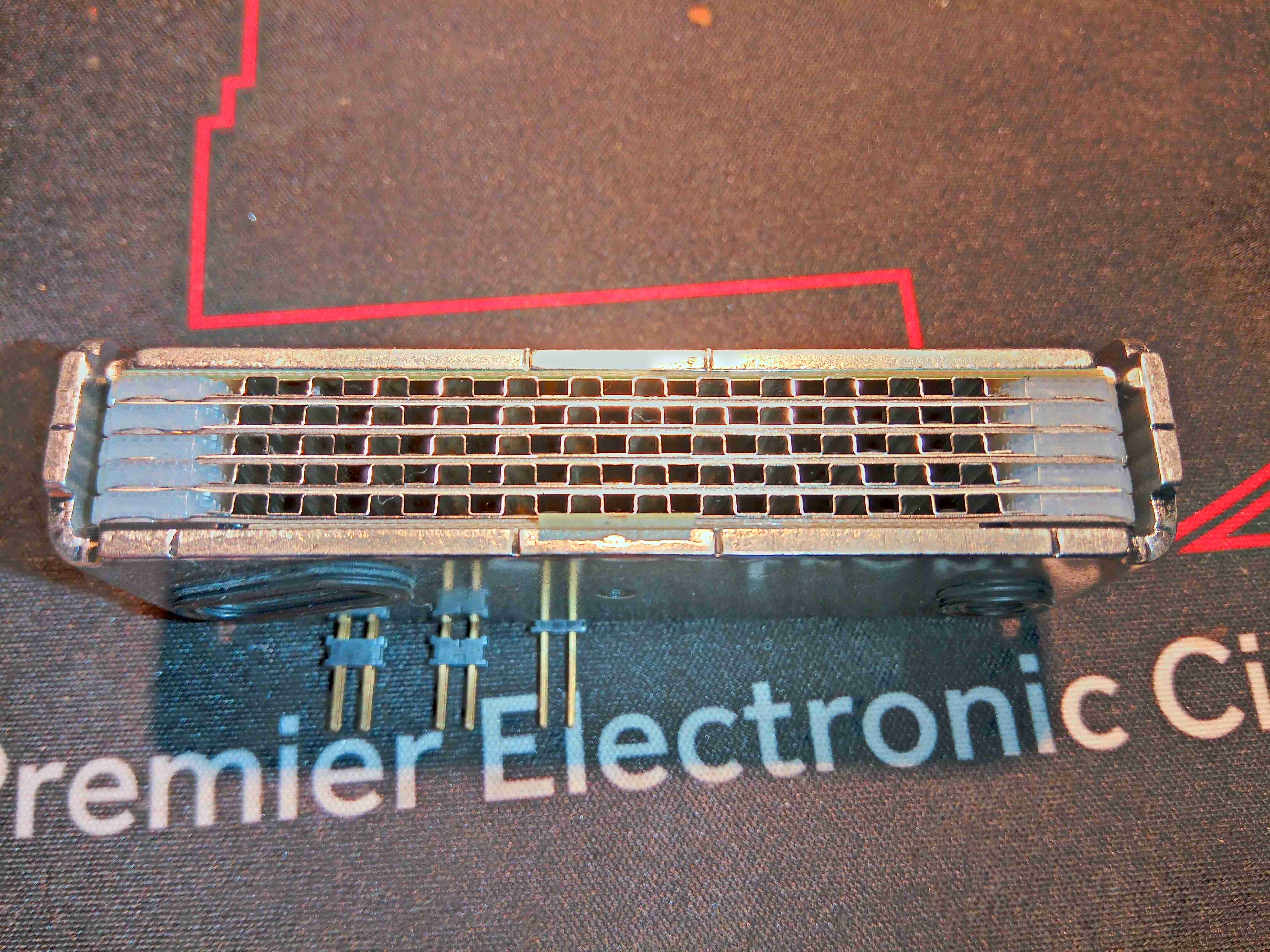
Gas Analysis Cell
Here’s the gas analyser cell itself, sandwiched under another board. There’s a temperature sensor on the side of the cell at the bottom, and even though there’s many pins on the header here, only a couple are actually used for the IR emitter.
IR Emitter
Removing the screws from the top allows the board to be removed, which exposes the Mid-IR emitter component with an exposed element. This looks to be very fragile, so I won’t be messing with this much. From metering the connections, this appears to be driven at about 2v from the microcontroller.
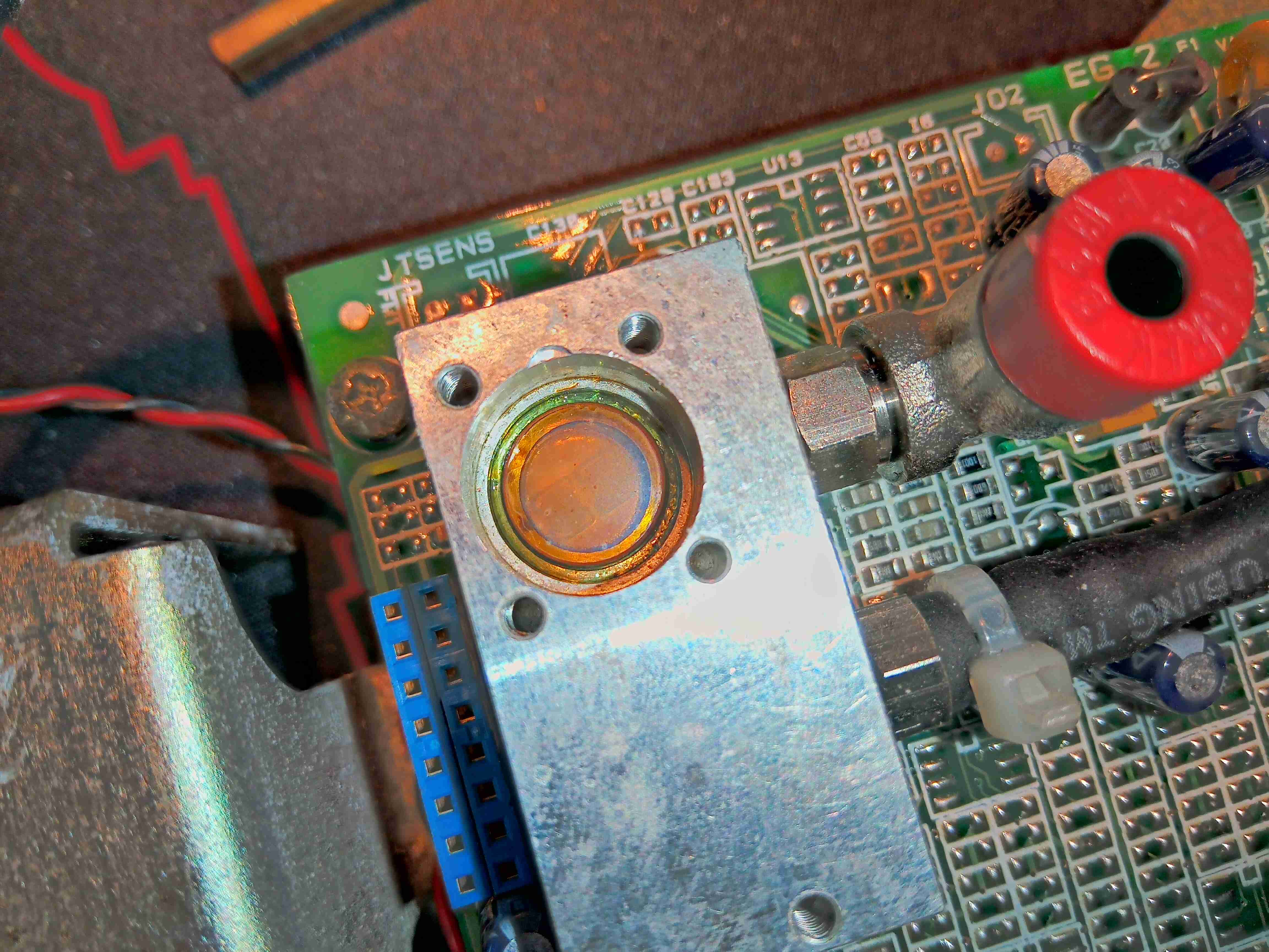
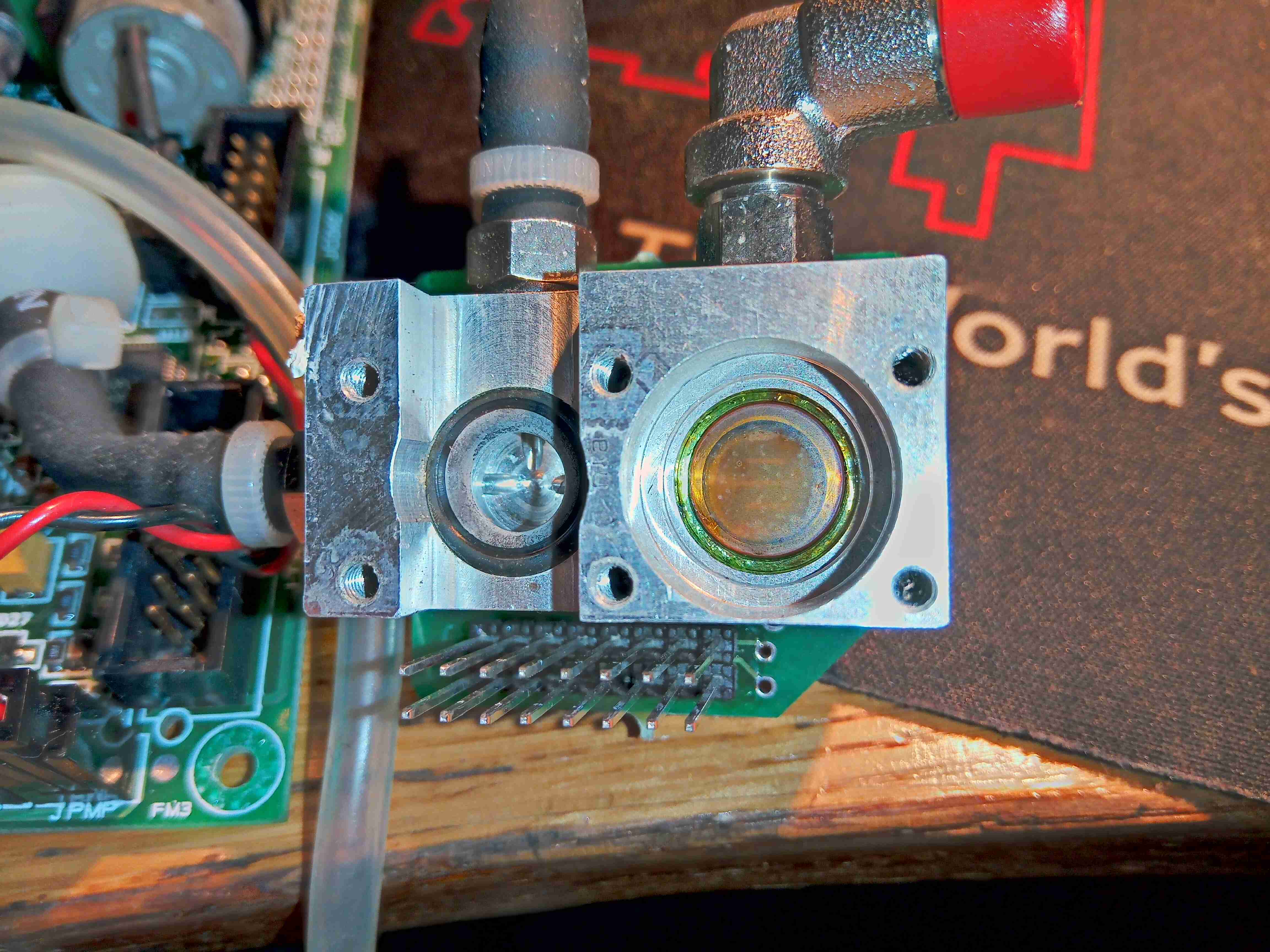
Top Of Gas Cell
The window into the gas cell looks to be made of something exotic – considering the IR application & the colour, this is probably Zinc Selenide.
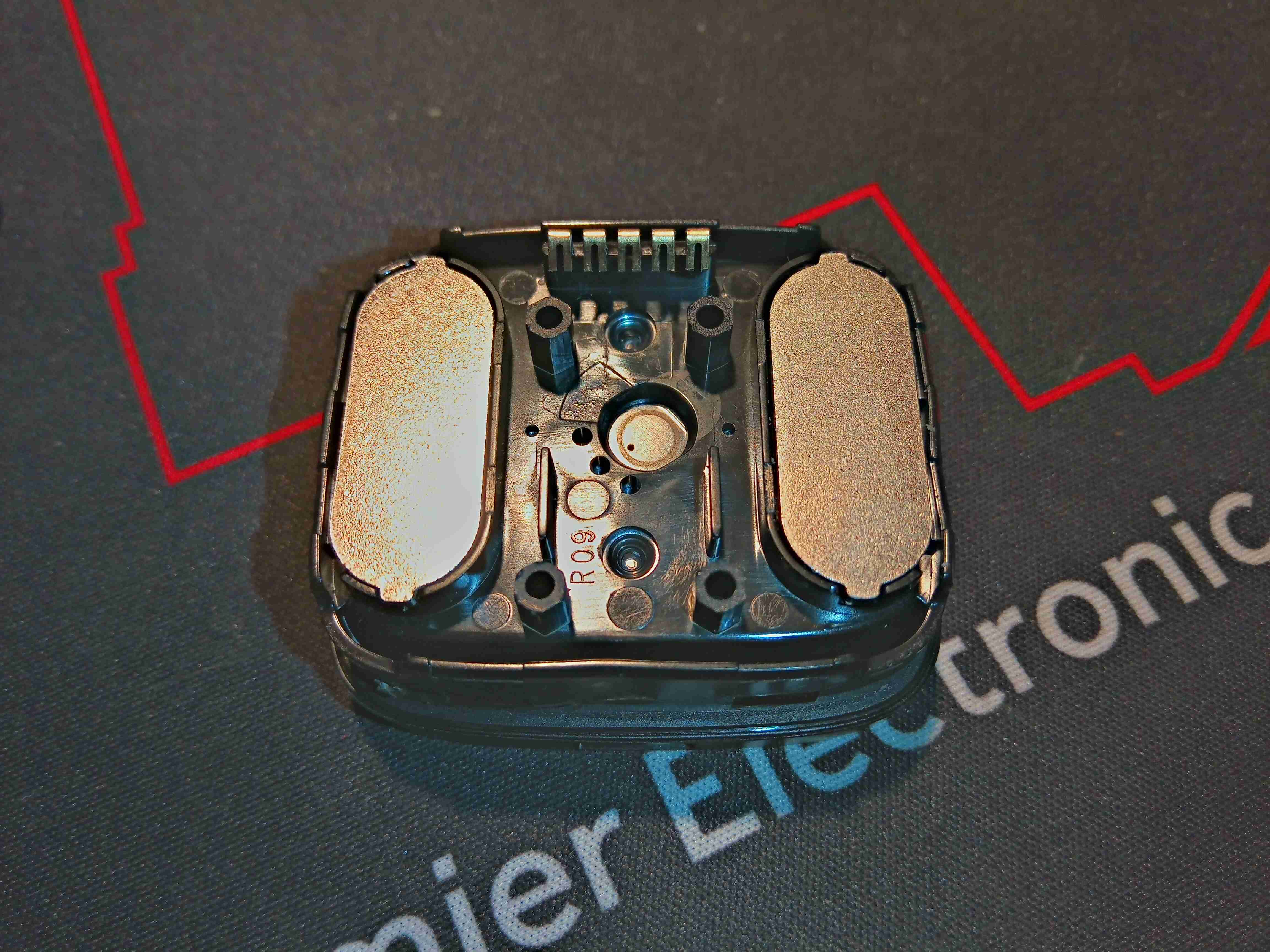
Gas Test Cell
Removing some more screws on the bottom exposes the bottom of the cell with another IR window, and an O-Ring where a pressure sensor sits.
Output Amplifiers
There’s a couple of very accurate LT1884 Rail-To-Rail Precision Op-Amps next to the cell, most likely used to measure the output from the sensor itself.
Mid-IR Sensor & Pressure Sensor
Finally, there is a dual-window thermopile sensor, and a pressure sensor. I wasn’t able to get any information on either of these, but I did find some ranges of sensors for Mid-IR measurement operations, that mentions a wavelength around 10µm for R-134a spectroscopy.
I will try to get this module going & measuring some gases, if I can work out how to talk to it – I already know the serial lines so it’s just working out a command set. If anyone has any information on these, please do get in touch! A service manual for the refrigerant machine this came out of would be good!
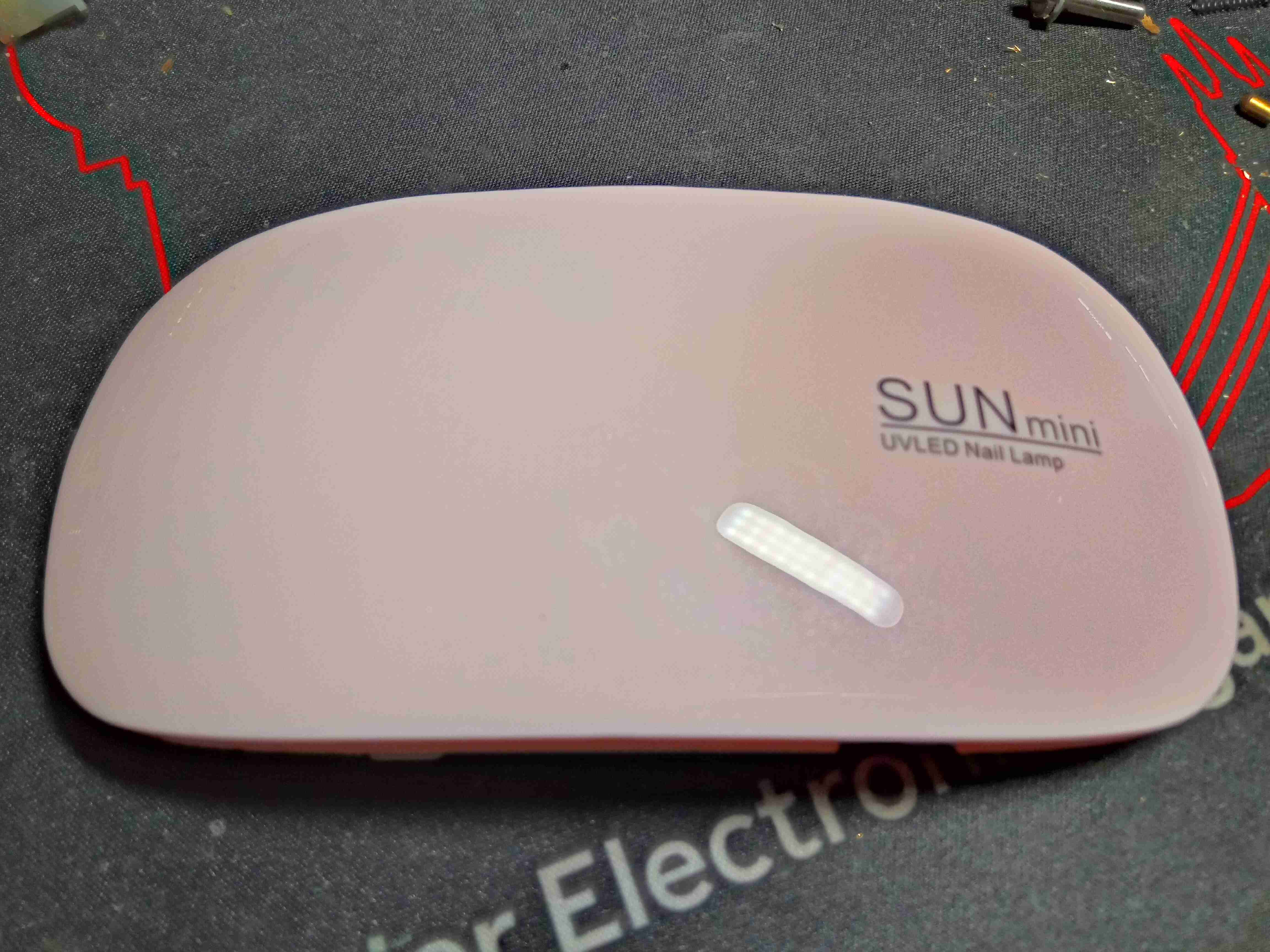
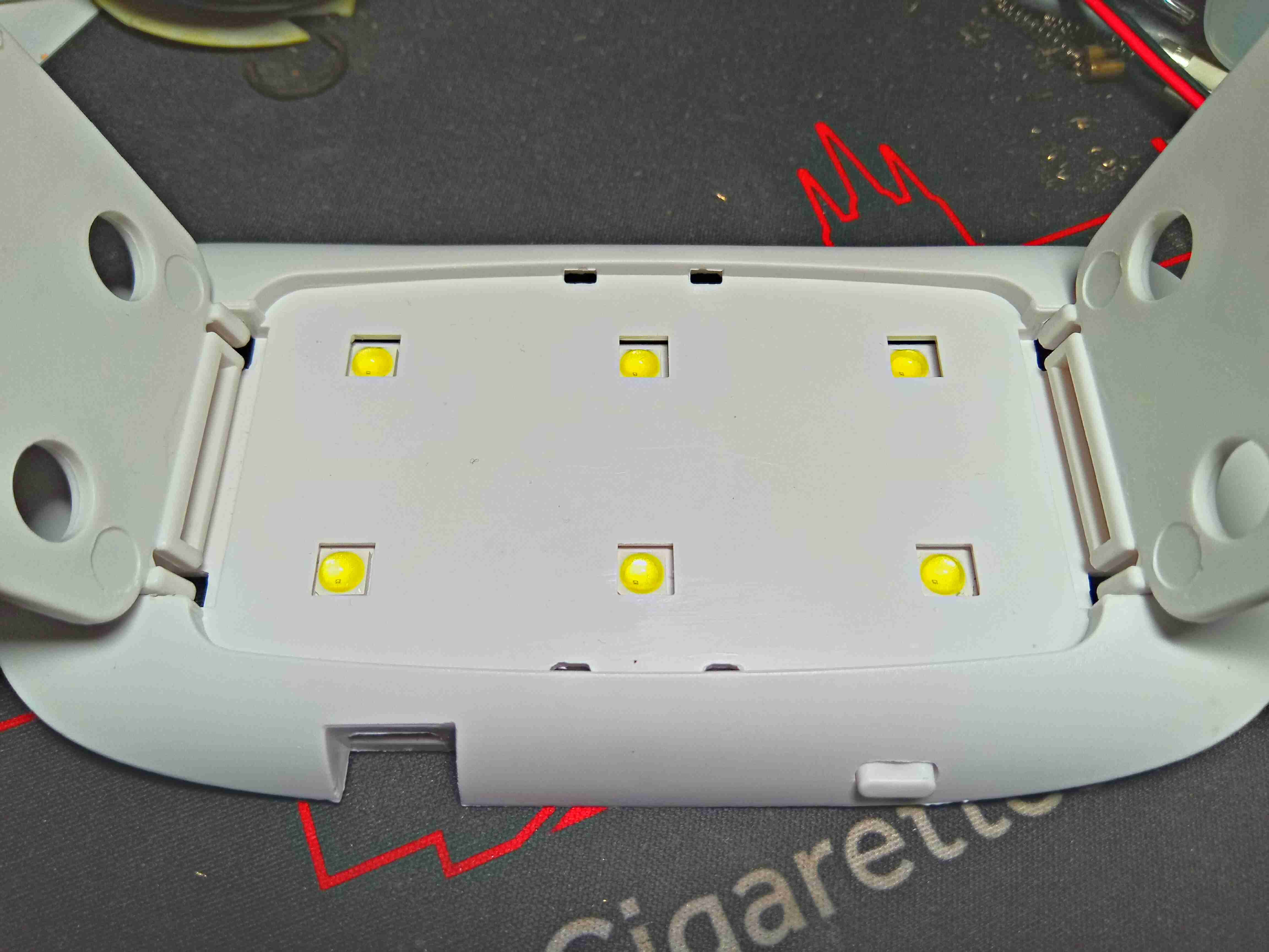
Time for another eBay delight! This is a little UV lamp for curing false nail glues. These are definitely taking over from the older Fluoroescent tube based units, and seem to work well enough. In my case, they work well for exposing UV-sensitive PCB substrates for etching as well!
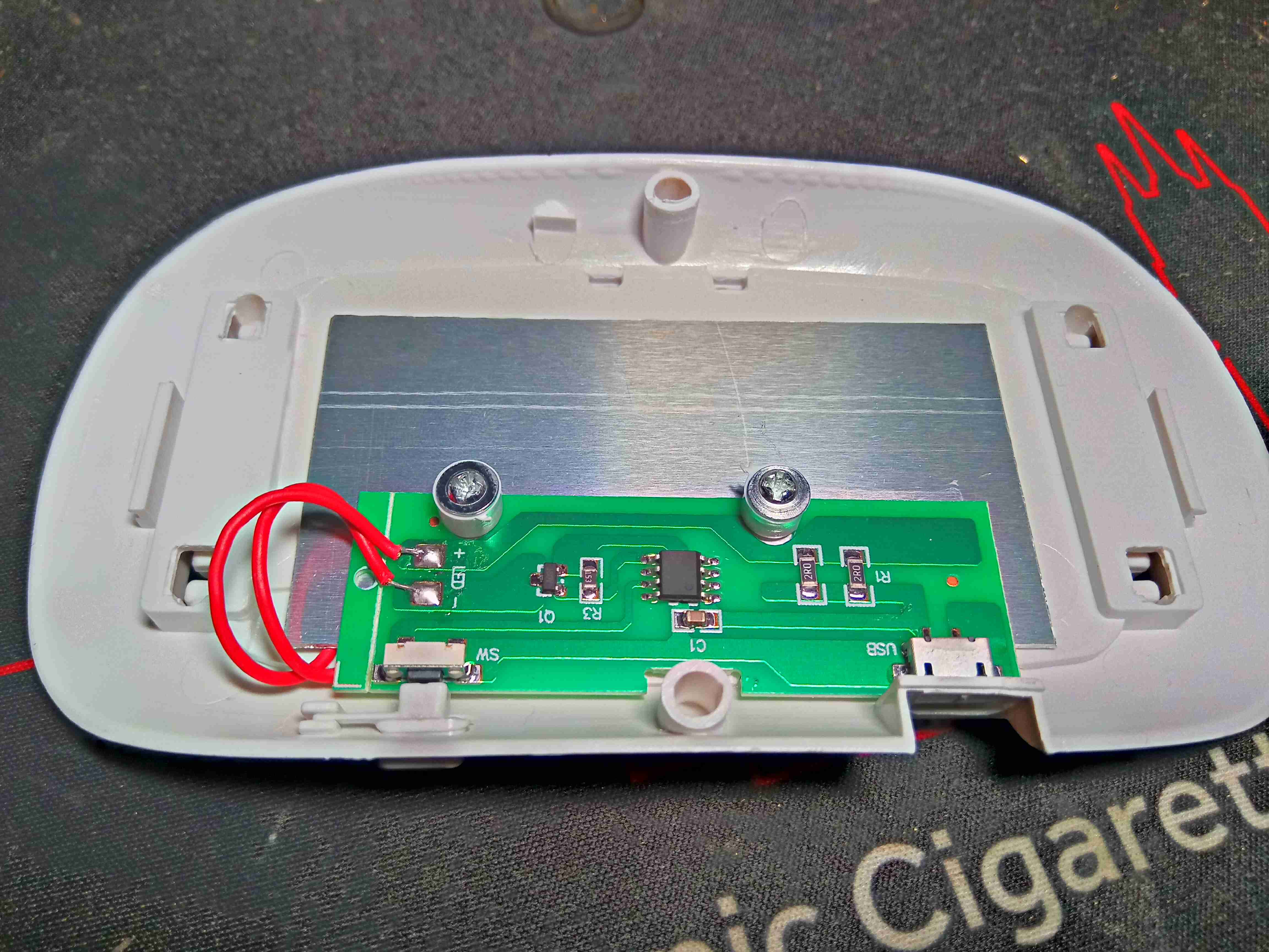
Here the cover has been unclipped from the body, no screws externally. There’s a small PCB, which holds an unmarked microcontroller, the USB input, the power & timer button, and a MOSFET for switching the LED current. A pair of 2Ω resistors in parallel on the right limit current through the LED array, in this case to 1.25A for an output power of 1.56W.
Lamp Bottom
Underneath the body are the apertures for the high-power UV LEDs. In this case there are 6 LEDs, each with a pair of dies of differing wavelengths. The legs fold up for storage.
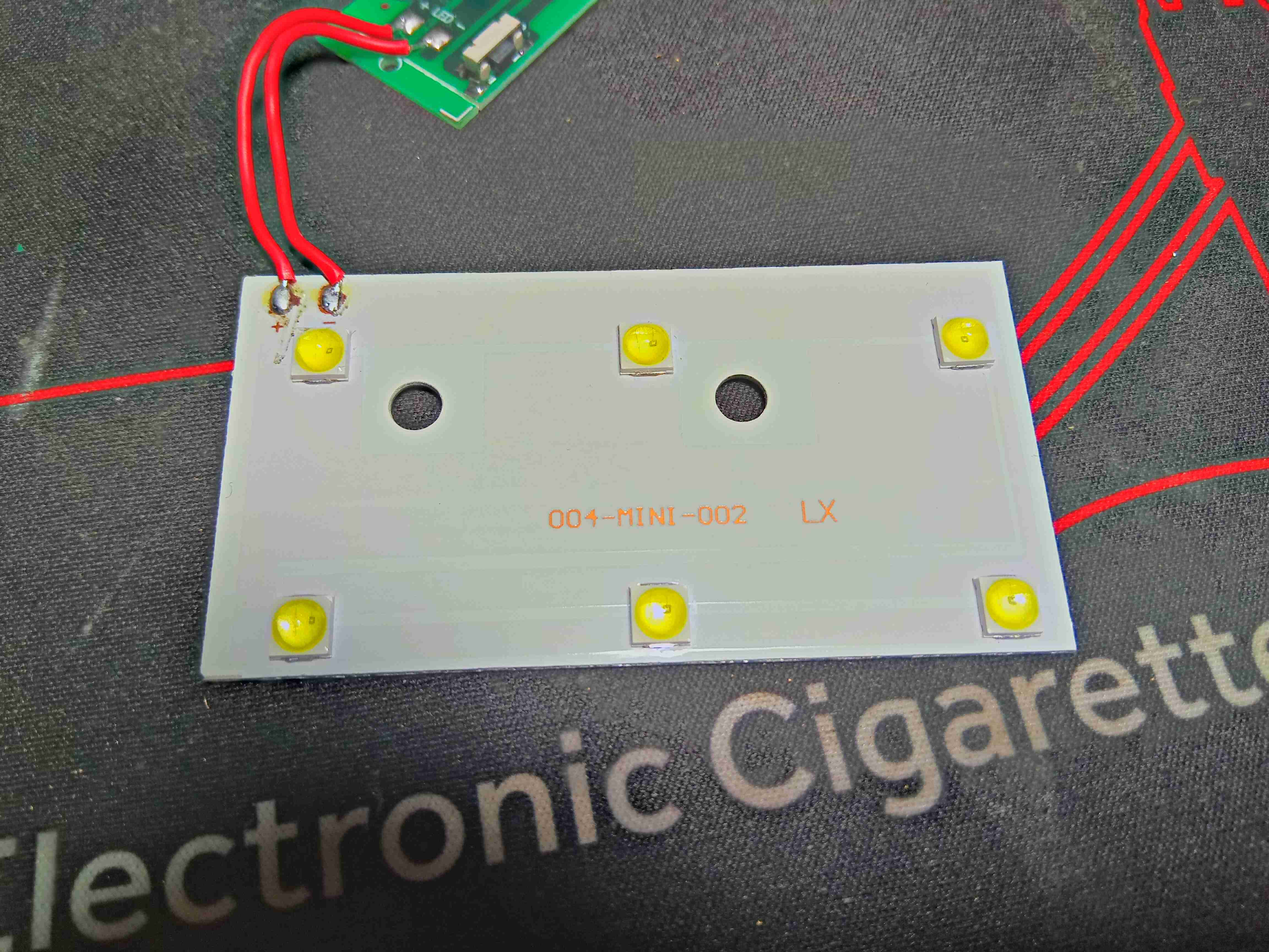
LED PCB
Removing the 2 screws inside allows the boards to come loose, and this is the front of the aluminium-cored PCB supporting the LEDs. In this case they are all wired in parallel.
Having had a wee issue with Jellyfin Media Server’s database this week after an upgrade, I decided to avoid the requirement for a 24 hour database rebuild, to start backing things up with Borgmatic. Borgmatic is a handy wrapper script to automate BorgBackup.
location:
    # List of source directories to backup.
    source_directories:
        - /etc/jellyfin
        - /var/lib/jellyfin

    # Path to BorgBackup repository
    repositories:
        - /export/ServerData/jellyfin_database

retention:
    # Retention policy for how many backups to keep.
    keep_daily: 7

consistency:
    # List of checks to run to validate your backups.
    checks:
        - repository
        - archives

hooks:
    # Custom preparation scripts to run.
    before_backup:
        -  systemctl stop jellyfin

    after_backup:
        - systemctl start jellyfin
This is a very simple configuration, which does the following steps:
Stops the Jellyfin server
Runs Borg on both configuration directories – /etc/jellyfin & /var/lib/jellyfin.
Checks the repo & existing archives for consistency
Restarts the Jellyfin server.
Now, whenever the SQLite 🤮 databases backing up the frontend decide to have a shitfit, it should be a relatively simple matter to restore to the last good backup. In my case I have a cronjob set to run every night. Once someone adds proper MySQL support, I will migrate over to a proper database server instance. 😉
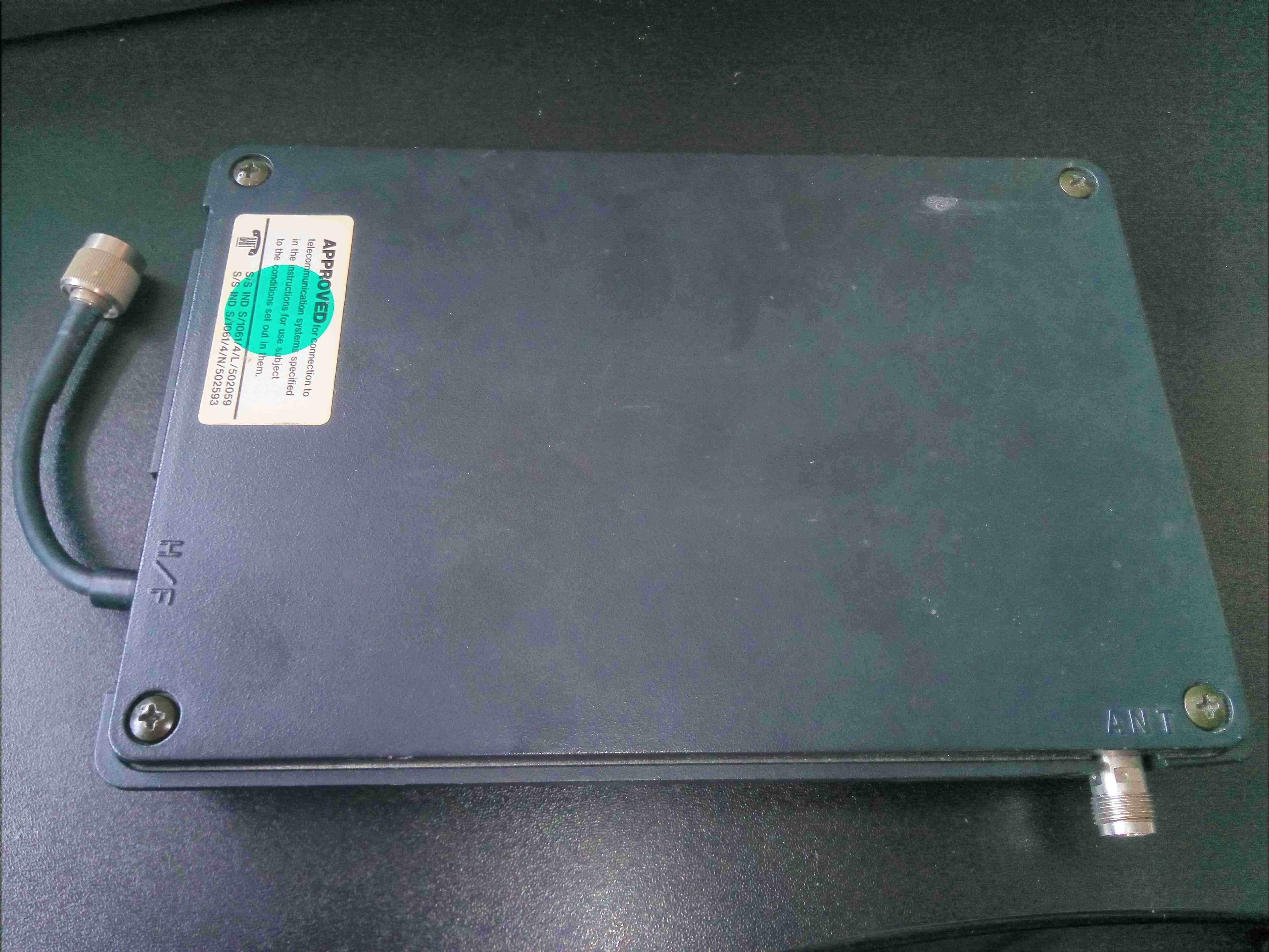
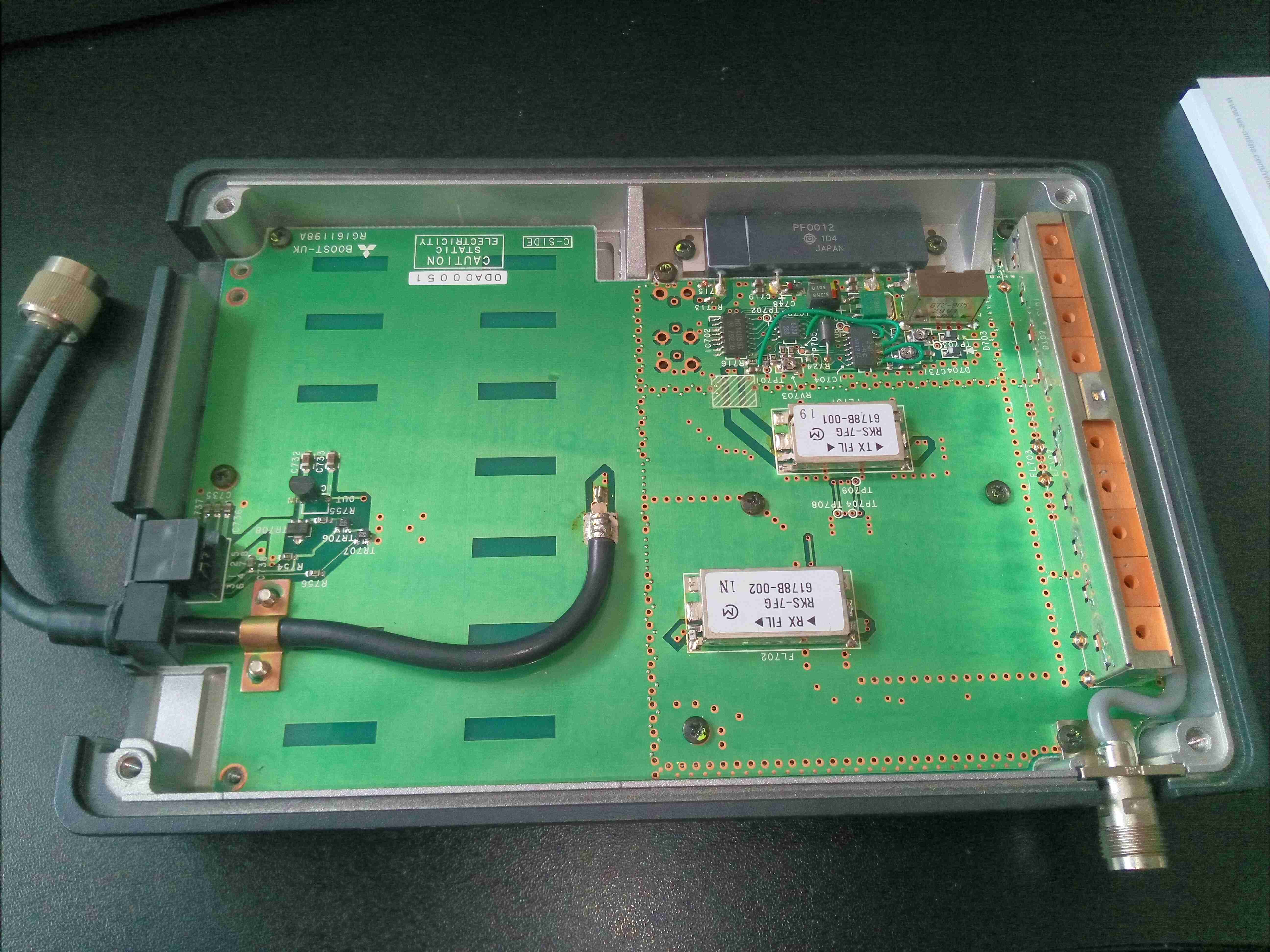
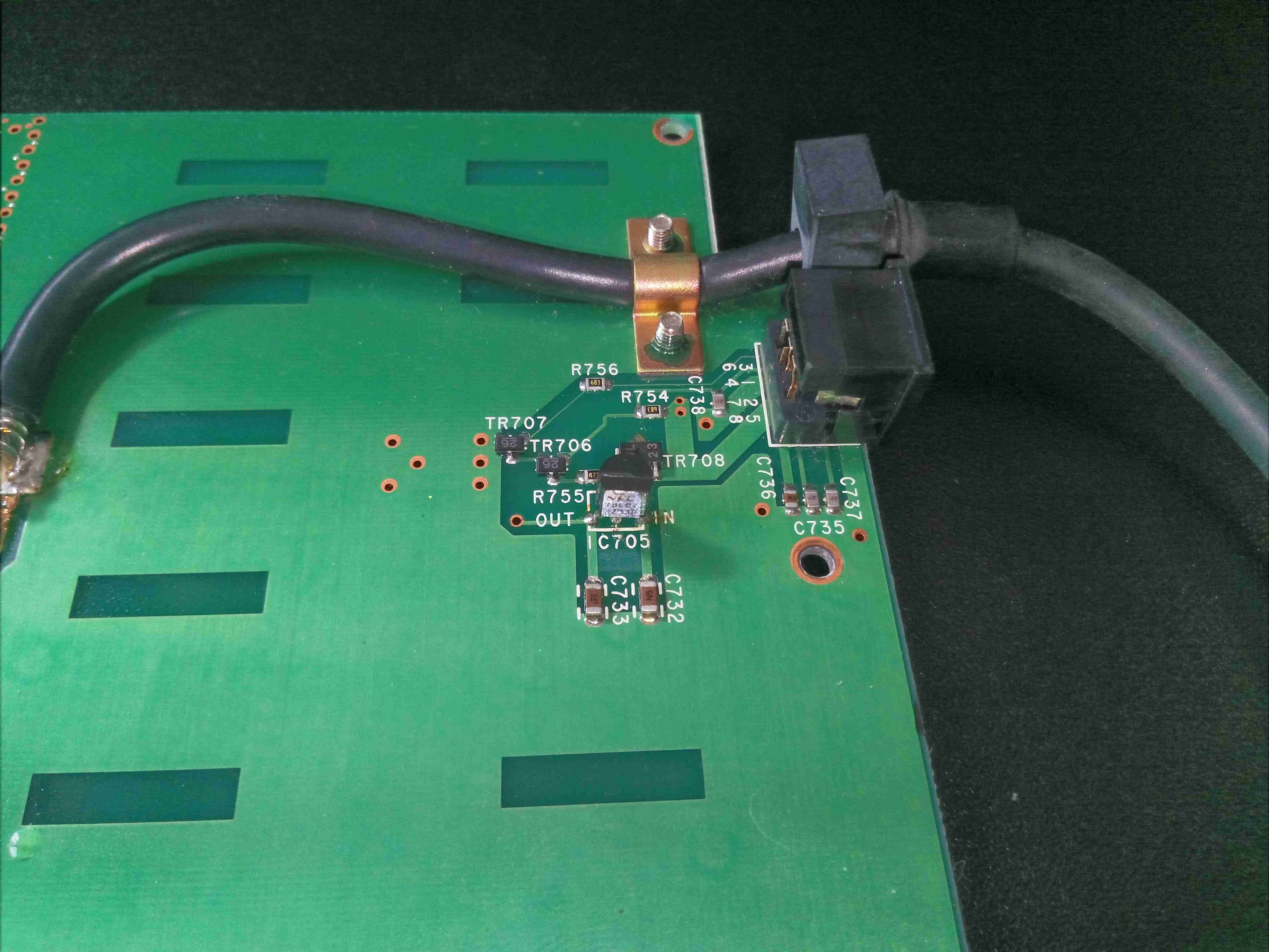
Here’s a blast from the past, before the time of GSM networks. This is a power amplifier from an Analogue mobile phone, on the ETACS system. This unit will output, according to the TACS standard, about 10W of RF power in the 900MHz band. RF connections on this unit are made via TNC connections, and a DIN connector for power & control. This unit is made of solid aluminium, no plastic casing here! The metal is needed for both RF shielding, and heatsinking capability for the power amplifier module inside.
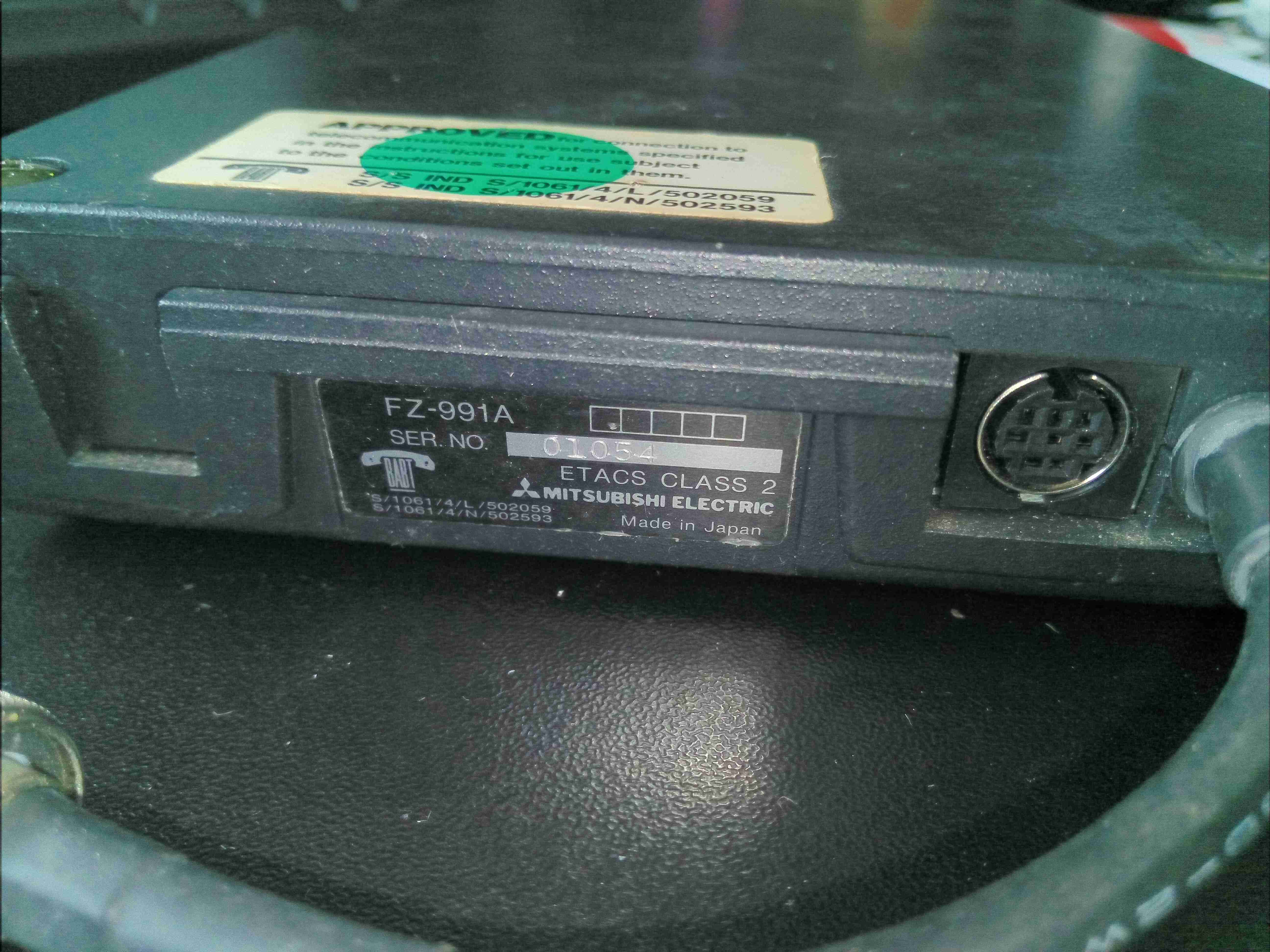
Rating Label & Control
Here’s the rating label, and the control connector.
Cover Removed
Removing 4 screws allows the lid to be removed from the cast base. There’s RF shielding gasket around the edge of the lid, along with the internal sections of the amplifier. The board is pretty sparsely populated. RF input is via the short cable on the left, and output to the antenna on the lower right.
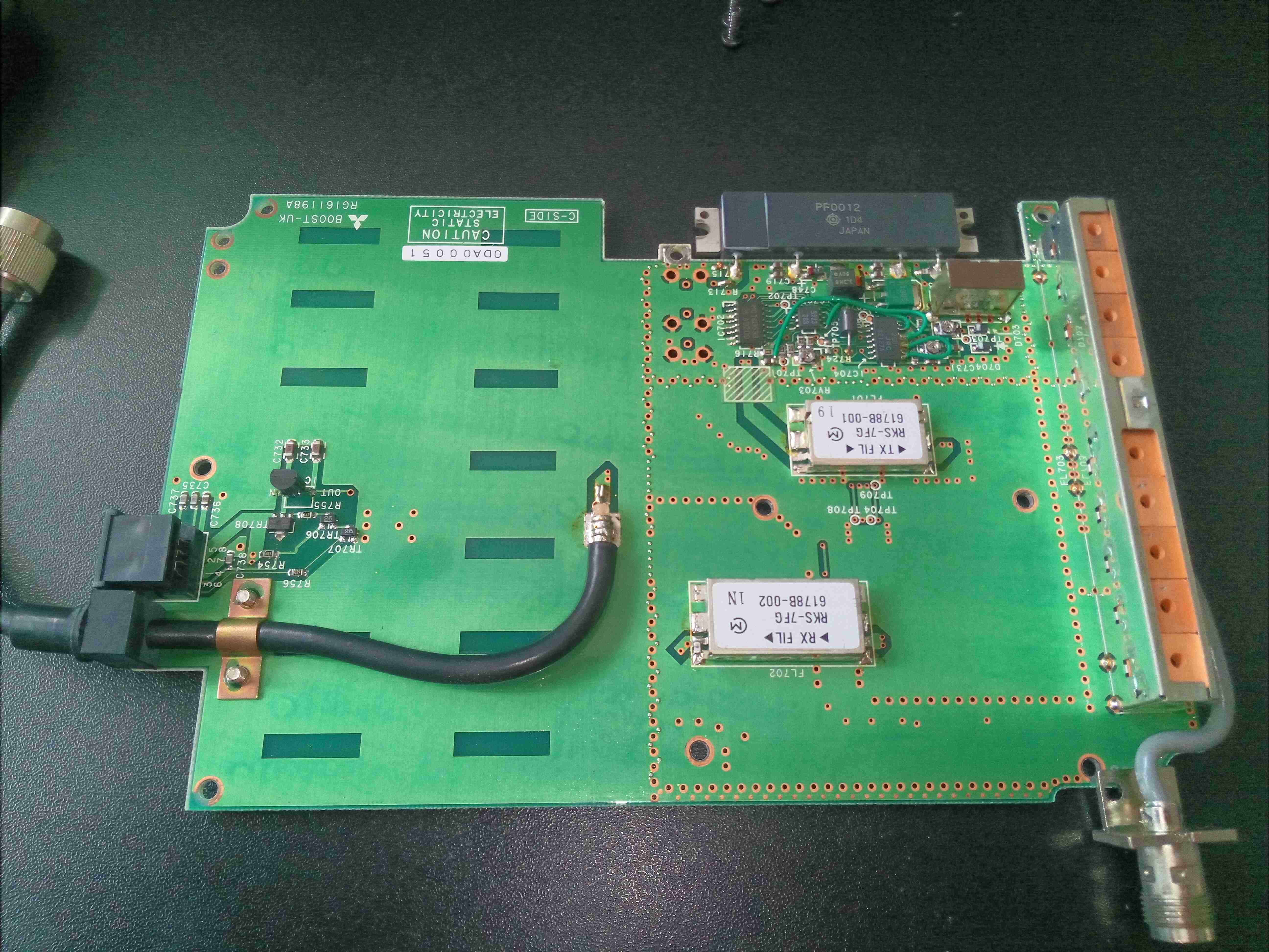
Bare PCB Top
A few more screws & the PCB comes out of the cast base.
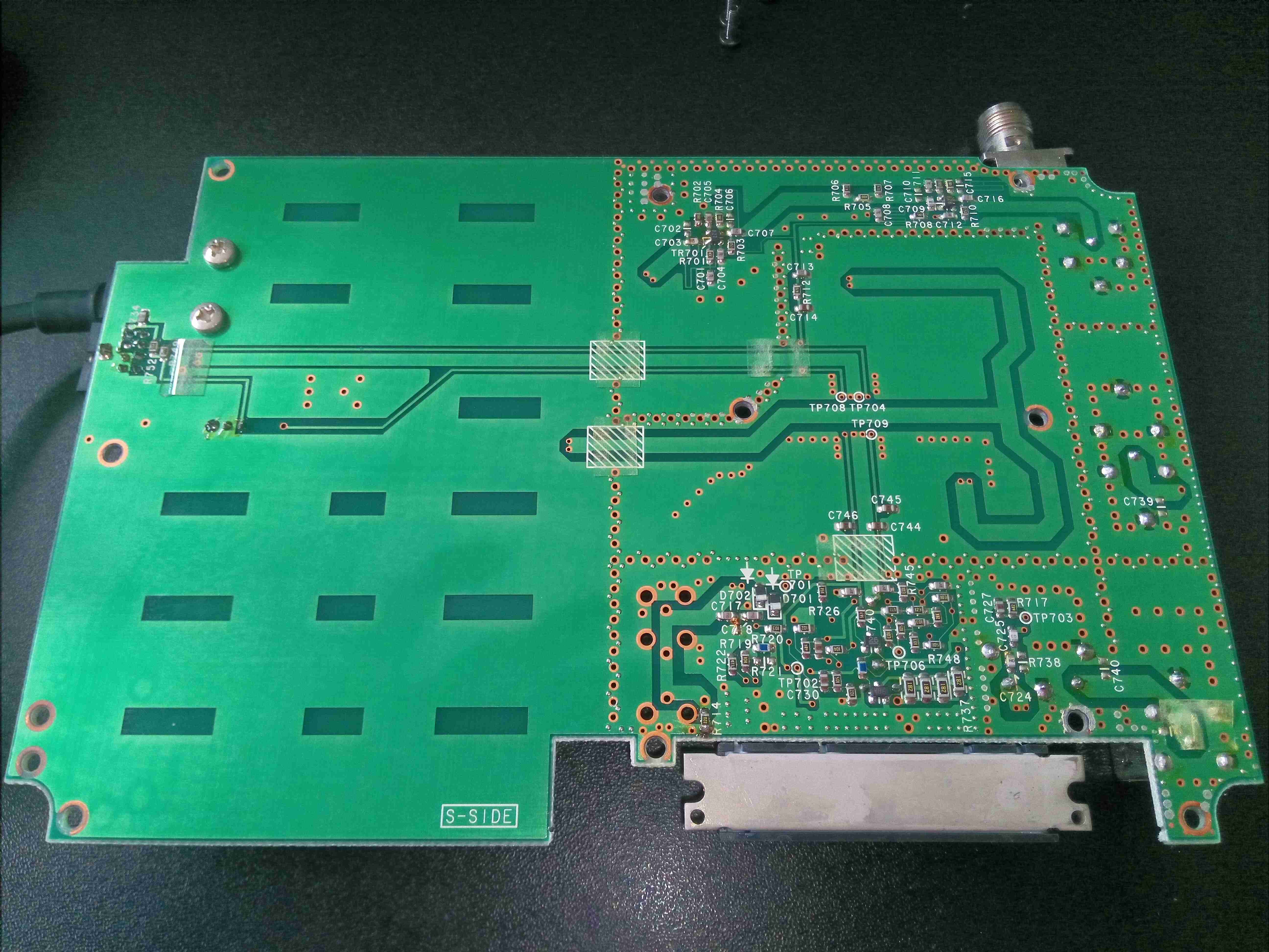
Bare PCB Bottom
Not much on the bottom of the board, apart from a lot of via stitching & passive components.
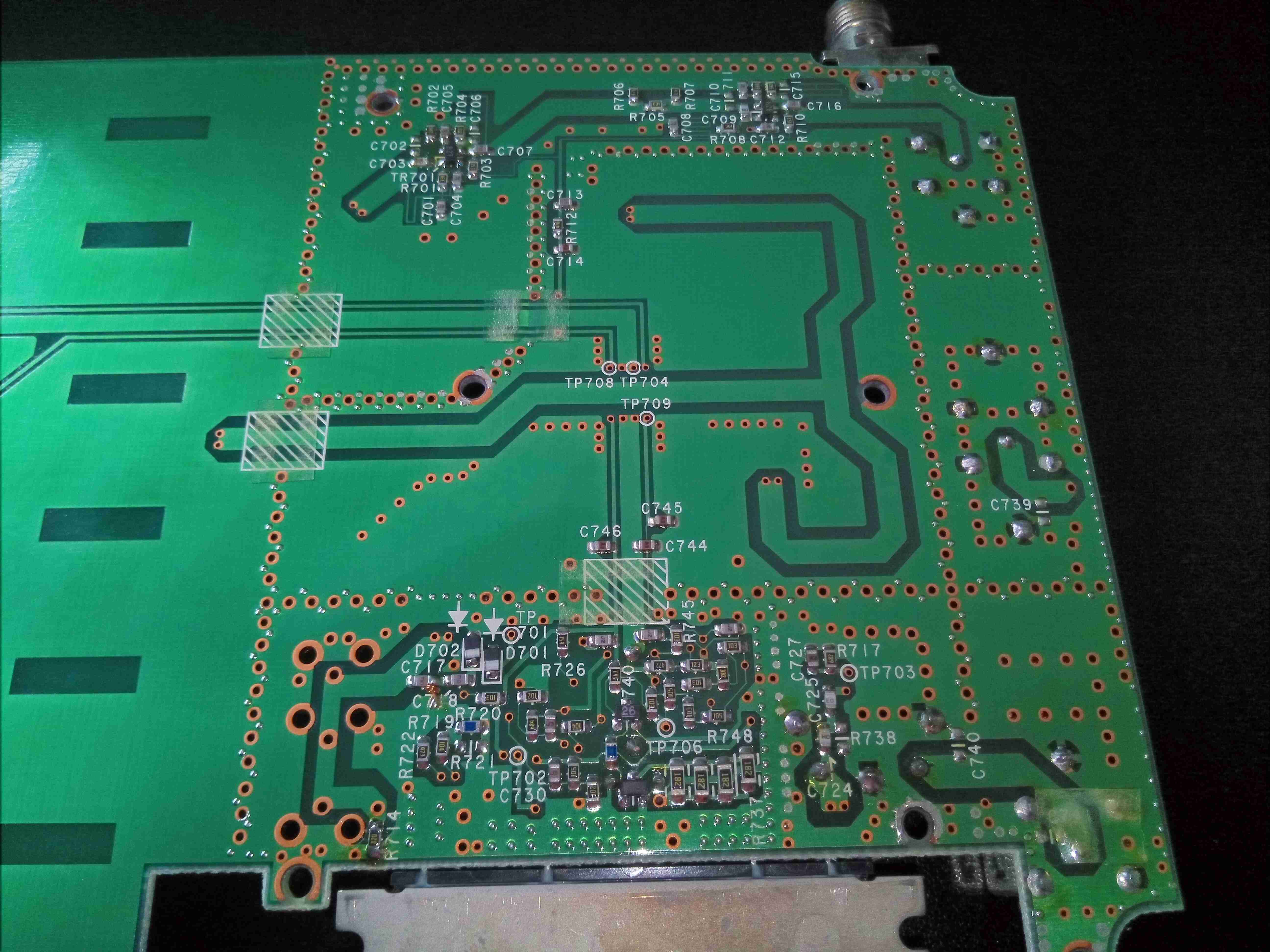
RF Section Tracks
Under the RF section is very dense with passives, and via stitching to separate the sections.
Voltage Regulator
There’s a 7v linear regulator near the power input connection, most likely to provide a biasing supply for the RF power section.
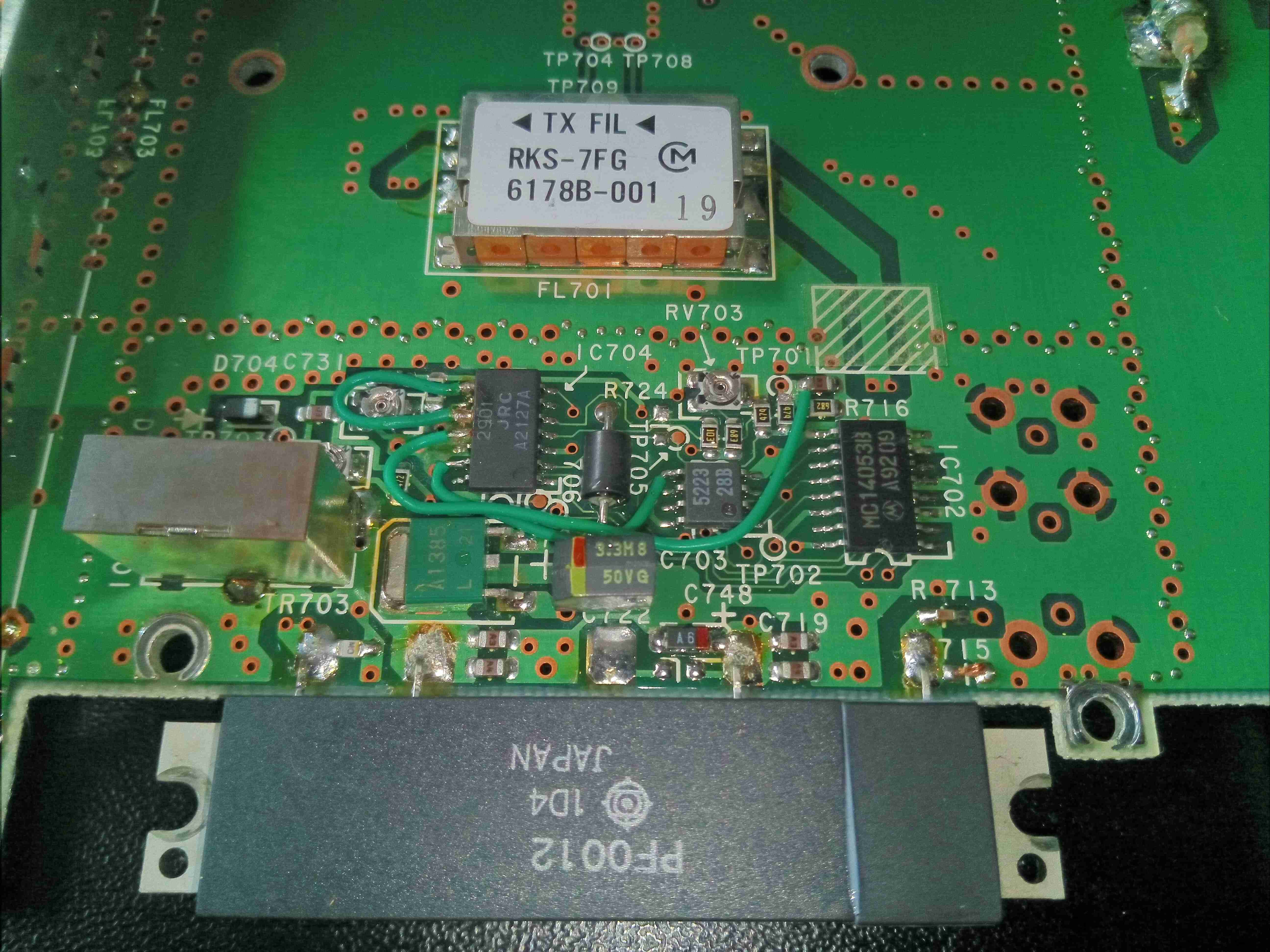
Amplifier Section
The main power amplifier is a Hitachi PF0012 module, these were very common in radios, and contain all the components required for an RF PA stage. I couldn’t find a specific datasheet for this module unfortunately. There are some support components inclusing a NMJ2901 Quad comparator from JRC, and a MC14051B Analogue Mux/Demux.
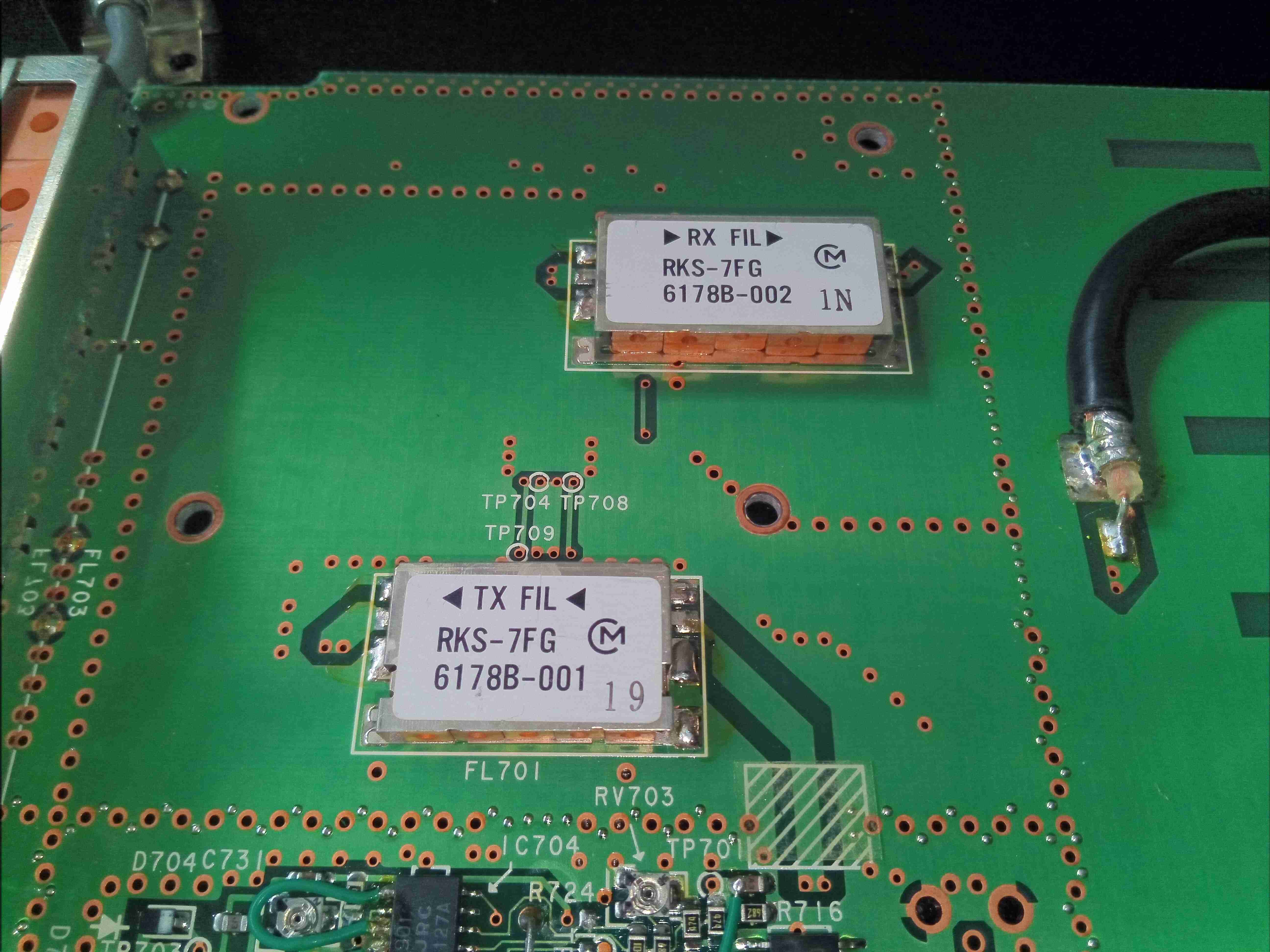
Duplexing Filters
Filtering of the TX & RX frequencies is done by this pair of units from MuRata
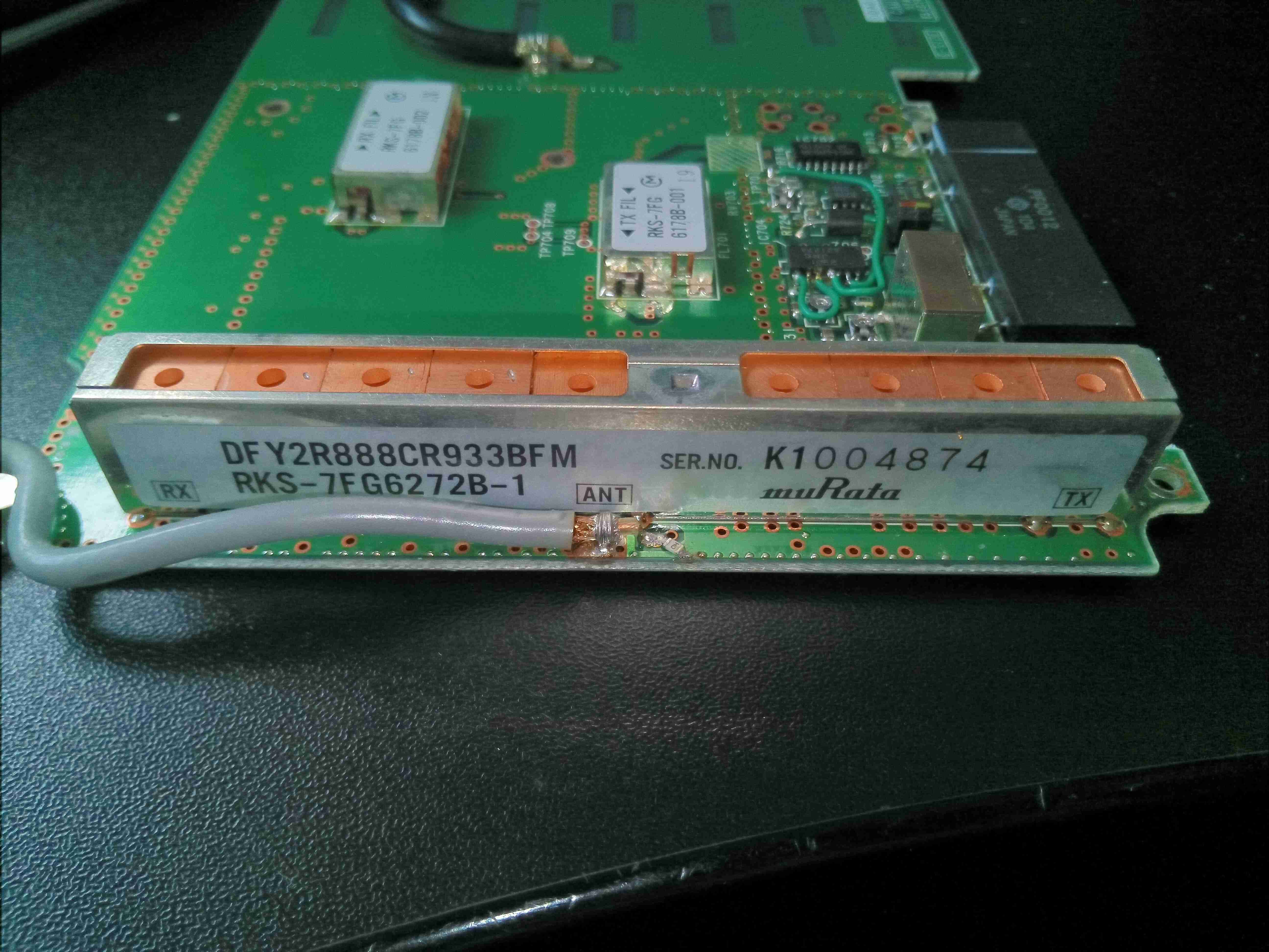
Antenna Duplexer
Finally, there’s an antenna duplexer on the output side, also from MuRata. Unfortunately no datasheets available for any of these parts.
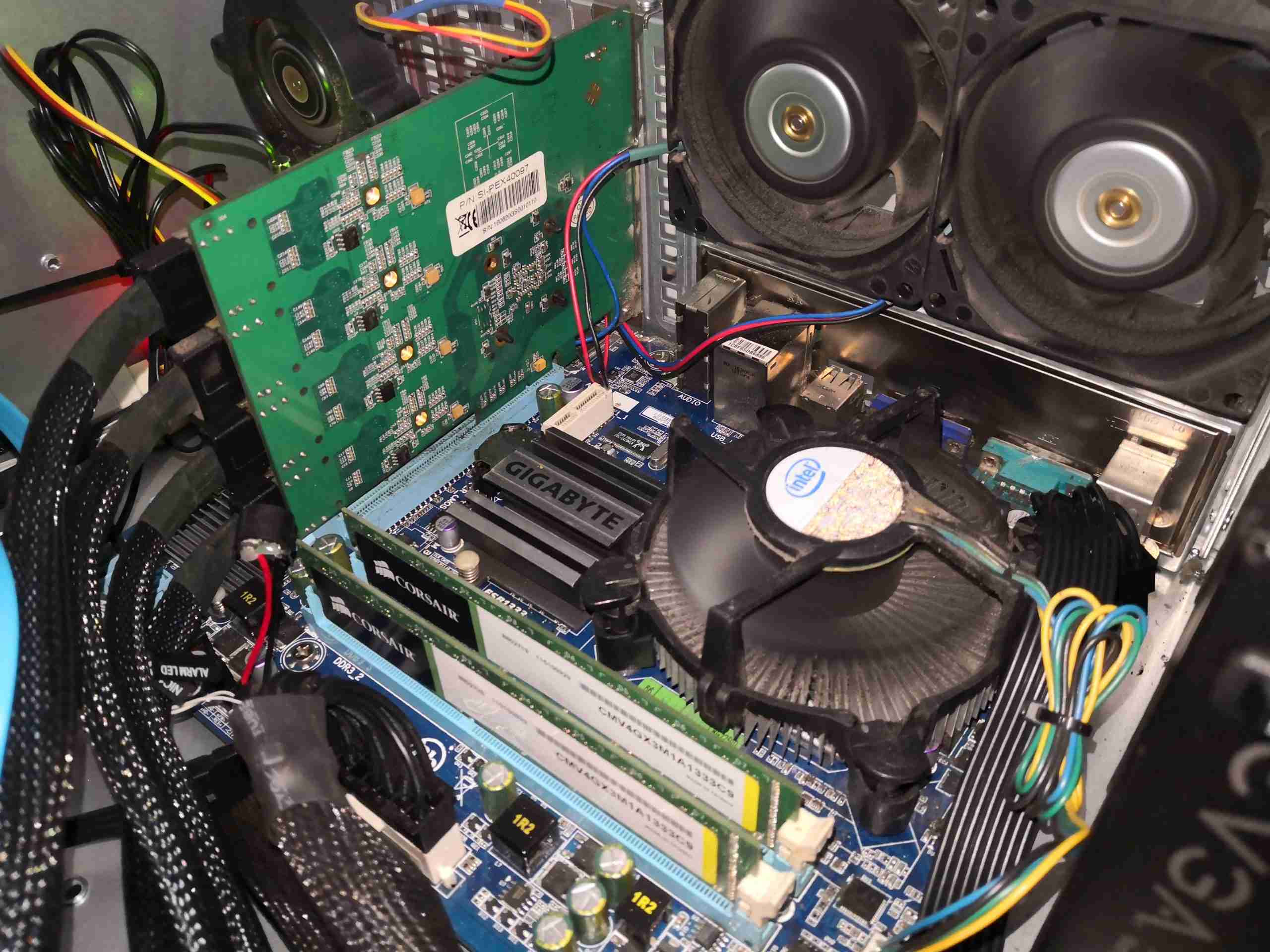
So, it’s time to finish off the upgrades to the core storage server on my network. Now a new motherboard, CPU & RAM have been obtained (MSI GA-X58-USB3), Core i7 950, 12GB), along with new SAS/SATA HBAs for the disk rack I can get everything fitted into place.
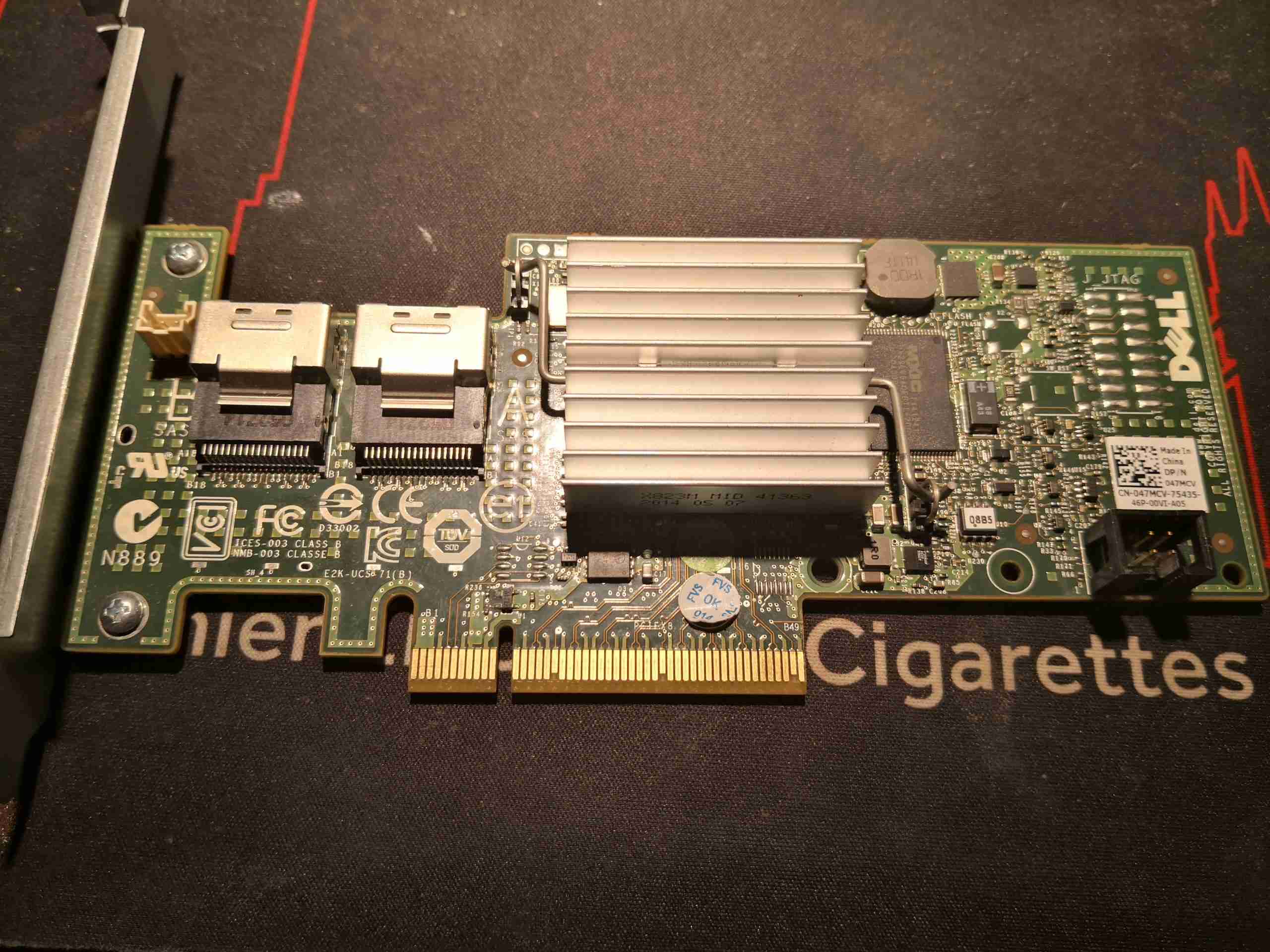
Dell H200 SAS RAID Card
Proper branded LSI HBA cards are expensive so I went with the cheaper option & obtained a pair of Dell H200 RAID cards. These have custom firmware flashed to them, but luckily can be crossflashed to a standard LSI firmware to become an LSI9211-8i card – providing 8 lanes of either SAS or SATA connectivity on a pair of SFF-8087 ports. Flashing these cards was very simple, once I managed to work my way into the EFI shell on my main machine, which I was using to do the flashing. Find all the firmware files & required software here:
One thing I left out from the flashing was a BIOS – this means that the boot process is speeded up, but also means the system BIOS cannot see the disks connected to the cards, so they’re not bootable. This isn’t a problem however, as I never plan on booting from the data storage disk array.
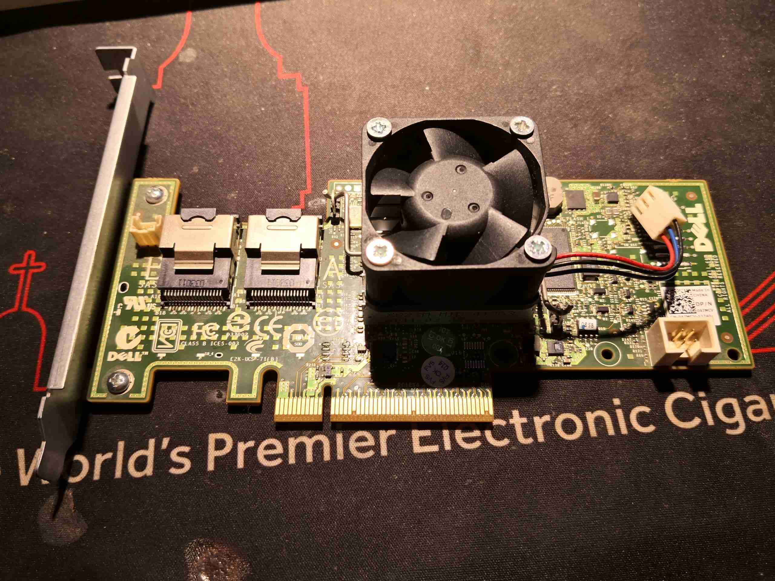
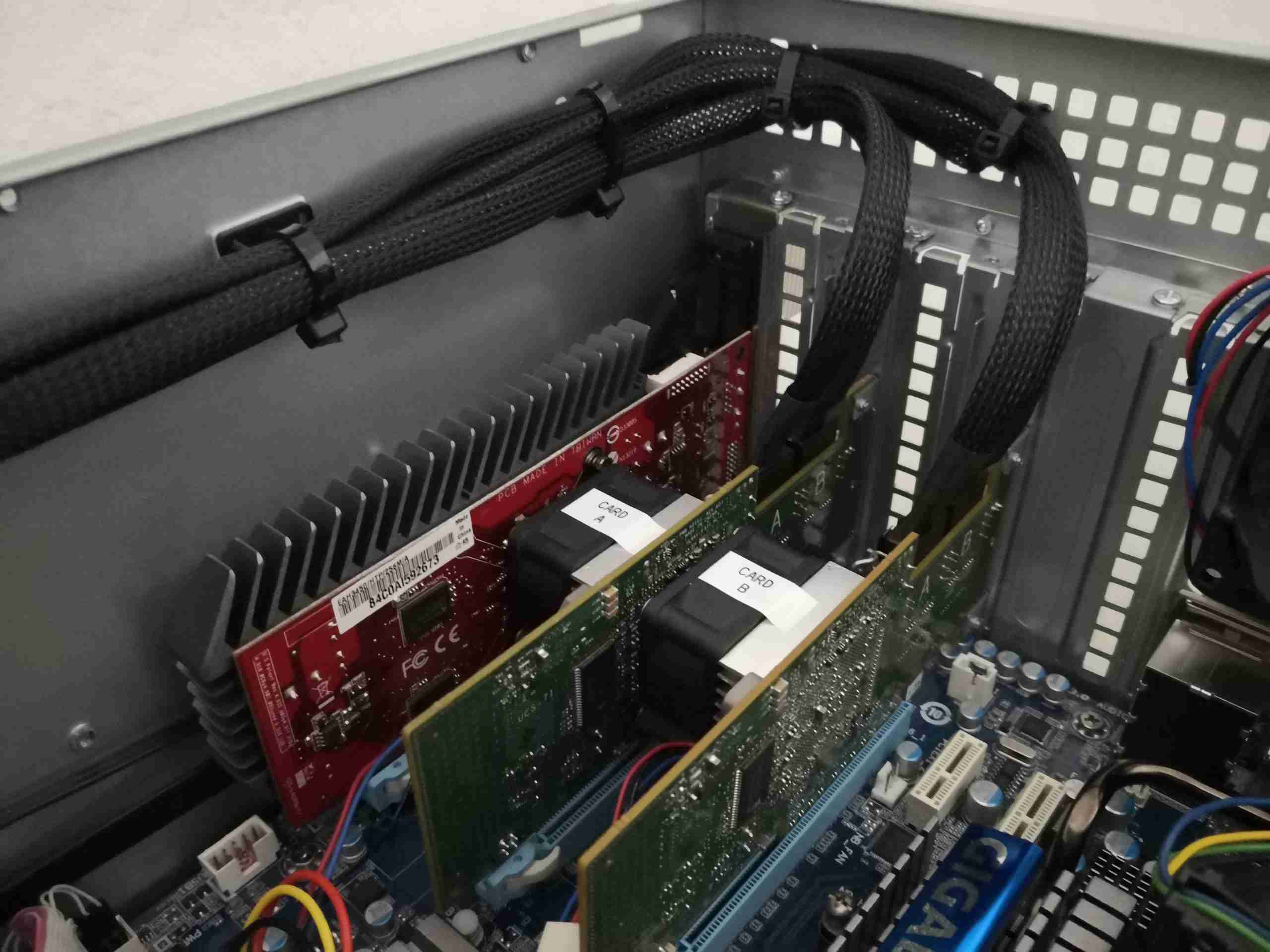
Active Cooling
The SAS2008 RoC (RAID on Chip) on these cards runs at around 8.5W thermal power, so some active cooling is required to keep temperatures within check. I have attached a 40mm fan to each card’s factory heatsink, using M3x25mm screws. Getting the screws to grab the heatsink was the tricky bit – I needed to crimp the outer corners of the fins together slightly, so when the screws are driven in, the gap is forced to expand, which grabs the threads. The fans will be connected to spare headers on the motherboard for speed monitoring.
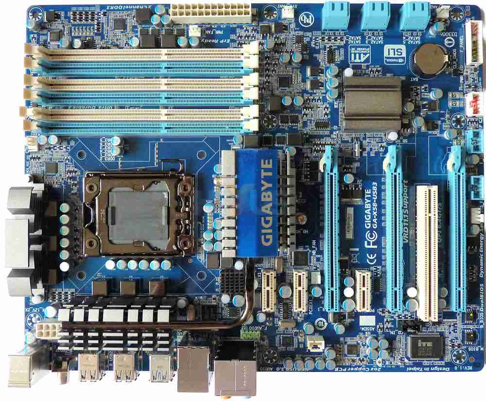
GA-X58-USB3
It was a struggle finding a motherboard with the required number of high-lane-count PCIe slots. Even on modern motherboards, there aren’t many about within a reasonable price range that have more than a single x16 slot, and since I’m going with the new HBAs, a single slot is no longer enough. The motherboard I managed to obtain has a pair of x16 slots, and a x4 slot (x16 physical), along with a 3 x1 slots. The only downside is there’s no onboard graphics on this motherboard, so an external card will be required. Another cheapie from eBay sorted this issue out.
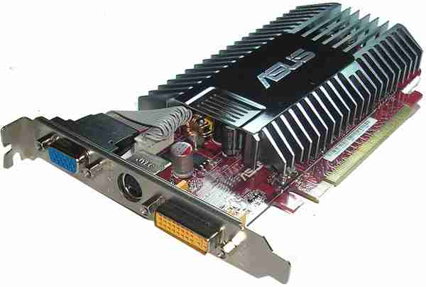
ATI Radeon HD3450
Since I need to use the x16 ports for the disk controllers, this card will have to go into the x4 slot.
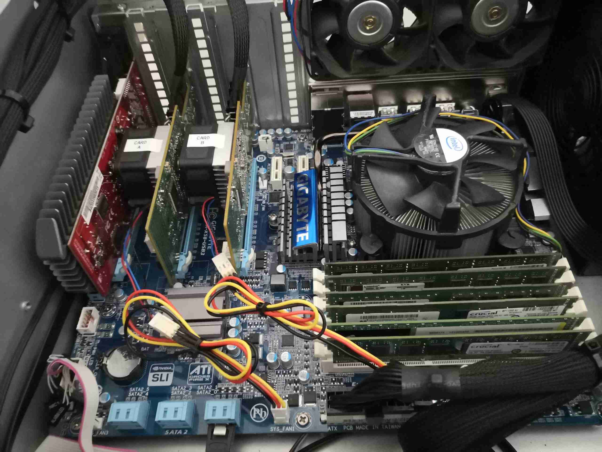
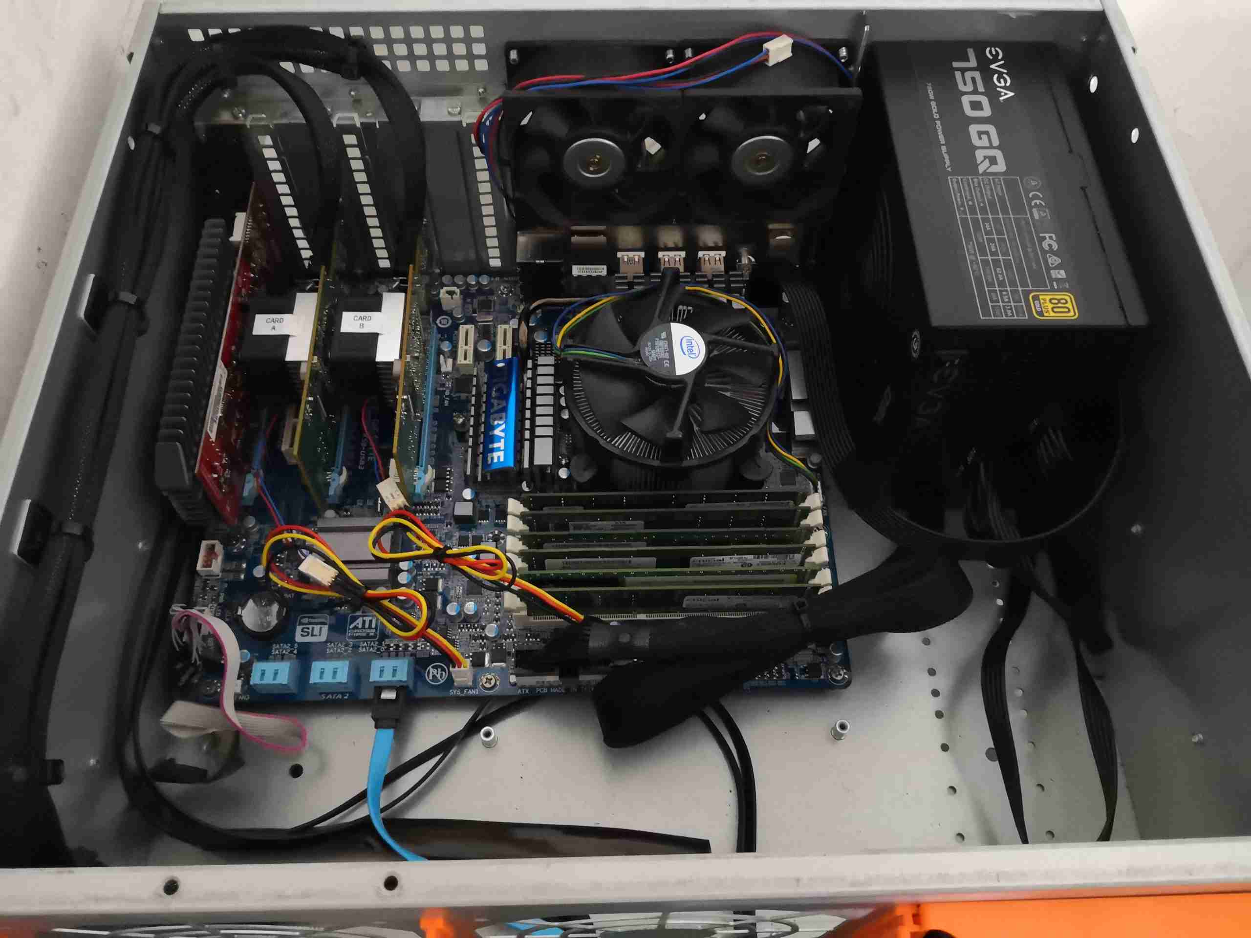
Motherboard Installed
Here the board has been installed into the new chassis, along with it’s IO shield. Both HBA cards are jacked into the x16 slots, with the SAS/SATA loom cables attached. I did have to grab longer cables – the originals I had were only 500mm, definitely not long enough to reach the ports on these cards, so 1m cables are used. The fans are plugged in with extensions to a pair of the headers on the motherboard, but the MB doesn’t seem to want to read RPM from those fans. Nevermind. While the fans are a little close to the adjacent cards, the heatsinks run just about warm to the touch, so there’s definitely enough airflow – not forgetting the trio of 120mm fans in the bulkhead just out of shot, creating a breeze right through the chassis.
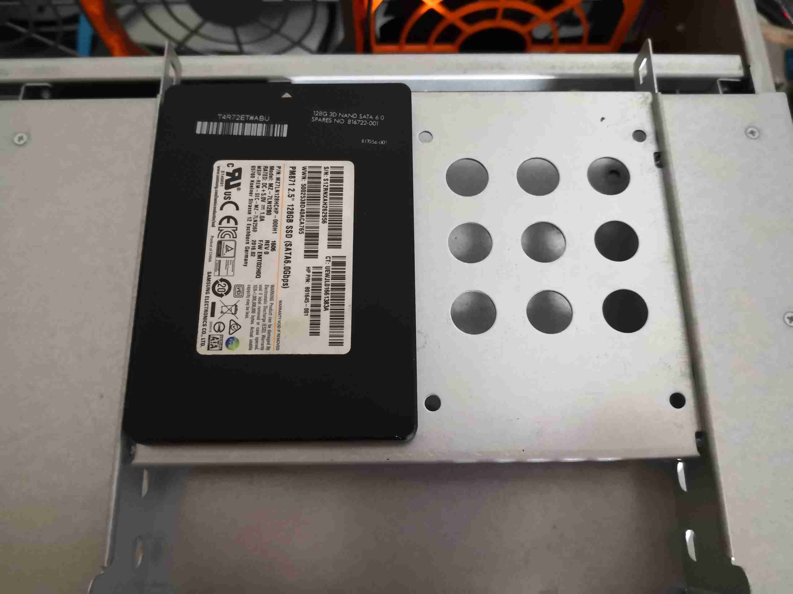
Boot SSD
Since the onboard SATA ports are in a better position, I was able to attach the boot SSD to the caddy properly, which helps tidy things up a bit. These slot into the 5-¾” bays on the front of the chassis, above the disk cage.
Loom Closeup
To take up the excess cable length, and tidy things up, the data loom to the disk cage is cable-tied to self-adhesive saddles on the side of the chassis. This arrangement also helps cooling air flow.
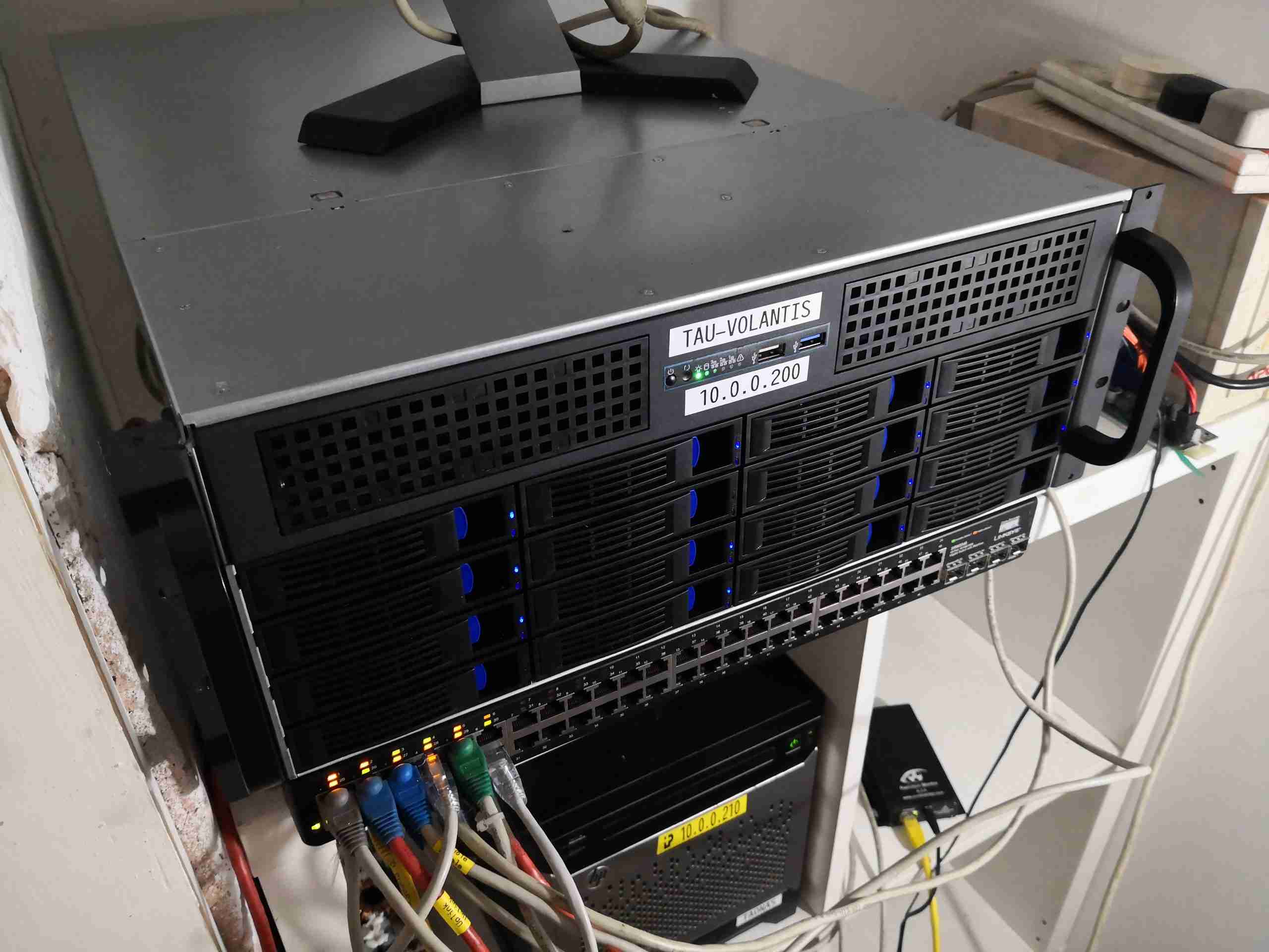
Server Overview
With the new components, and the cabling tied up, things inside the chassis look much cleaner. I’ve rationalised the power cabling to the disk backplanes down to a a pair of SATA power looms.
So I figured it was time to get a hardware update sorted for my network’s core storage server, which I have posted about before. The way I had the drives anchored to steel rails really doesn’t make moving or replacing disks easy, so a proper case needed to be sourced.
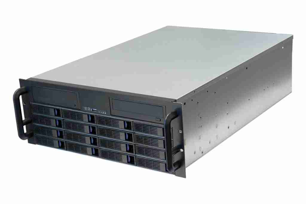
4U 16-Bay Hotswap Chassis
ServerCaseUK stocked 16-bay 4U chassis units, so one of these was ordered. These have 4 internal backplanes, with SFF-8087 Mini-SAS connections, so hooking into my existing 16-channel HBA card would be simple. In the current setup, the multi-lane cables are routed out via SFF-8088 connectors to the drive array, so this will tidy things up considerably.
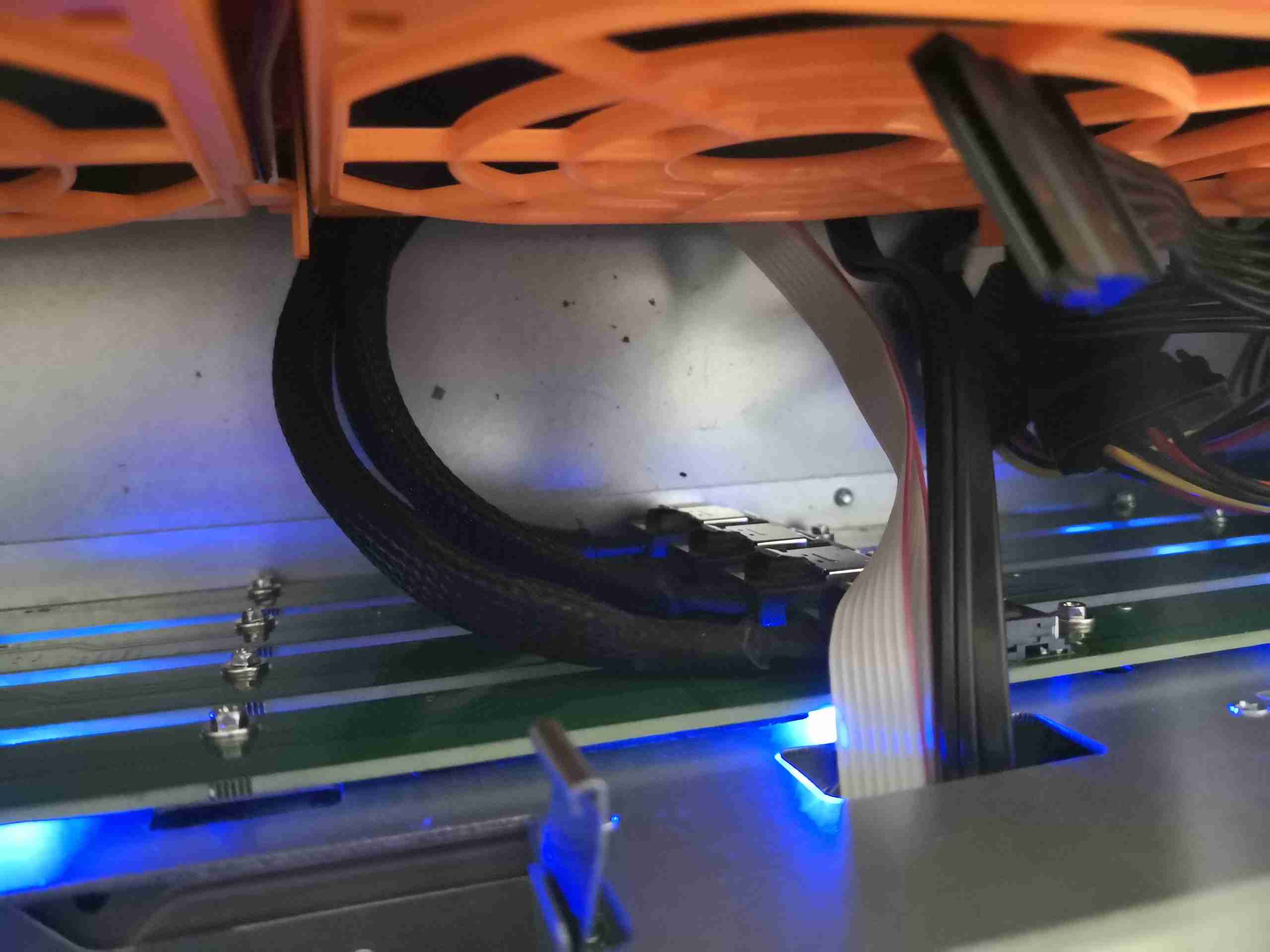
SFF-8087 Connections
The main data links are via these SFF-8087 connectors, each carrying 4 lanes of SATA.
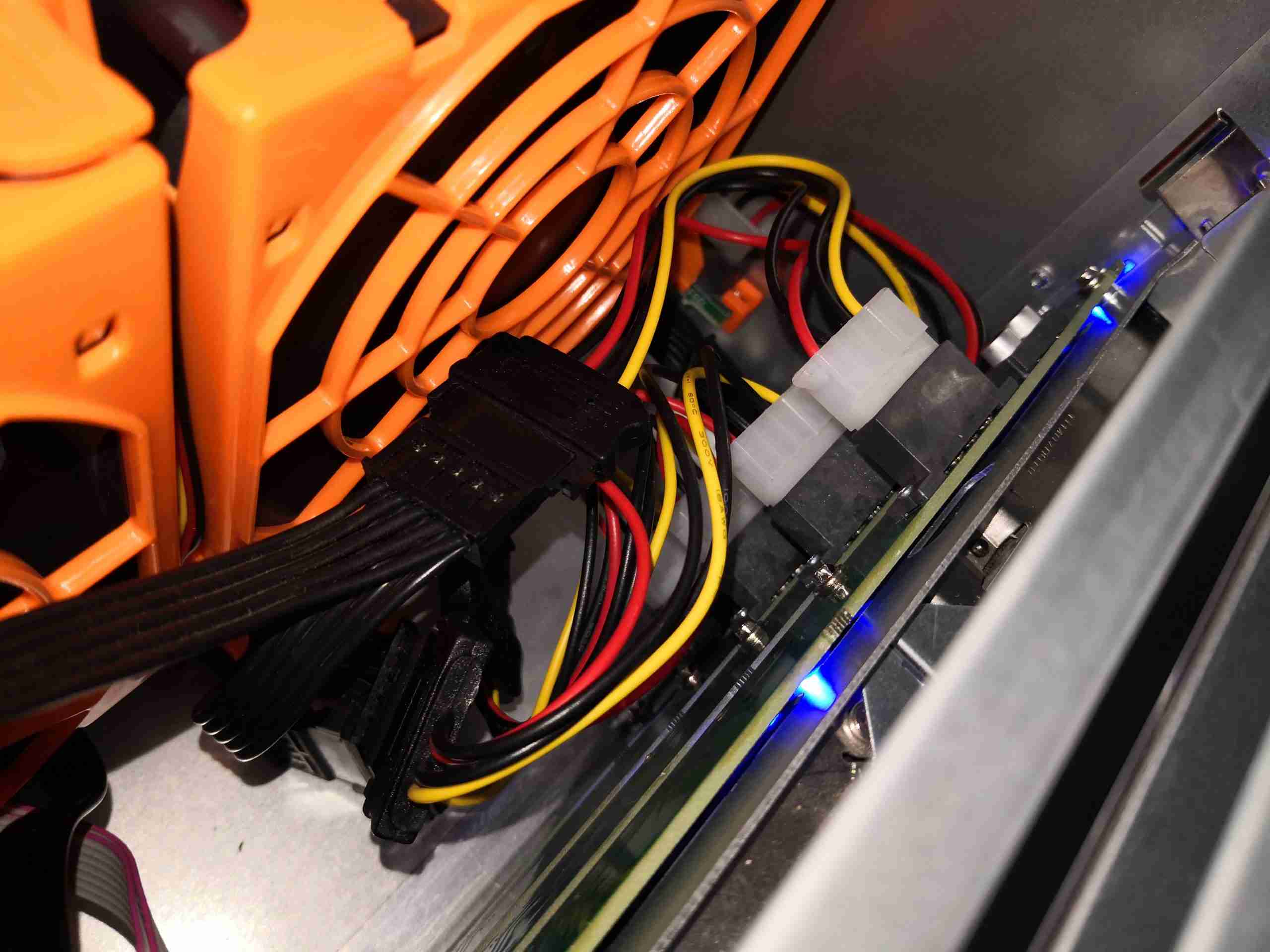
Backplane Power
Power is provided by 4x Molex connections, via SATA power adaptors (the good kind, which don’t create fire). There’s a 5th Molex hidden down the size of the last fan, which powers all 3 120mm fans.
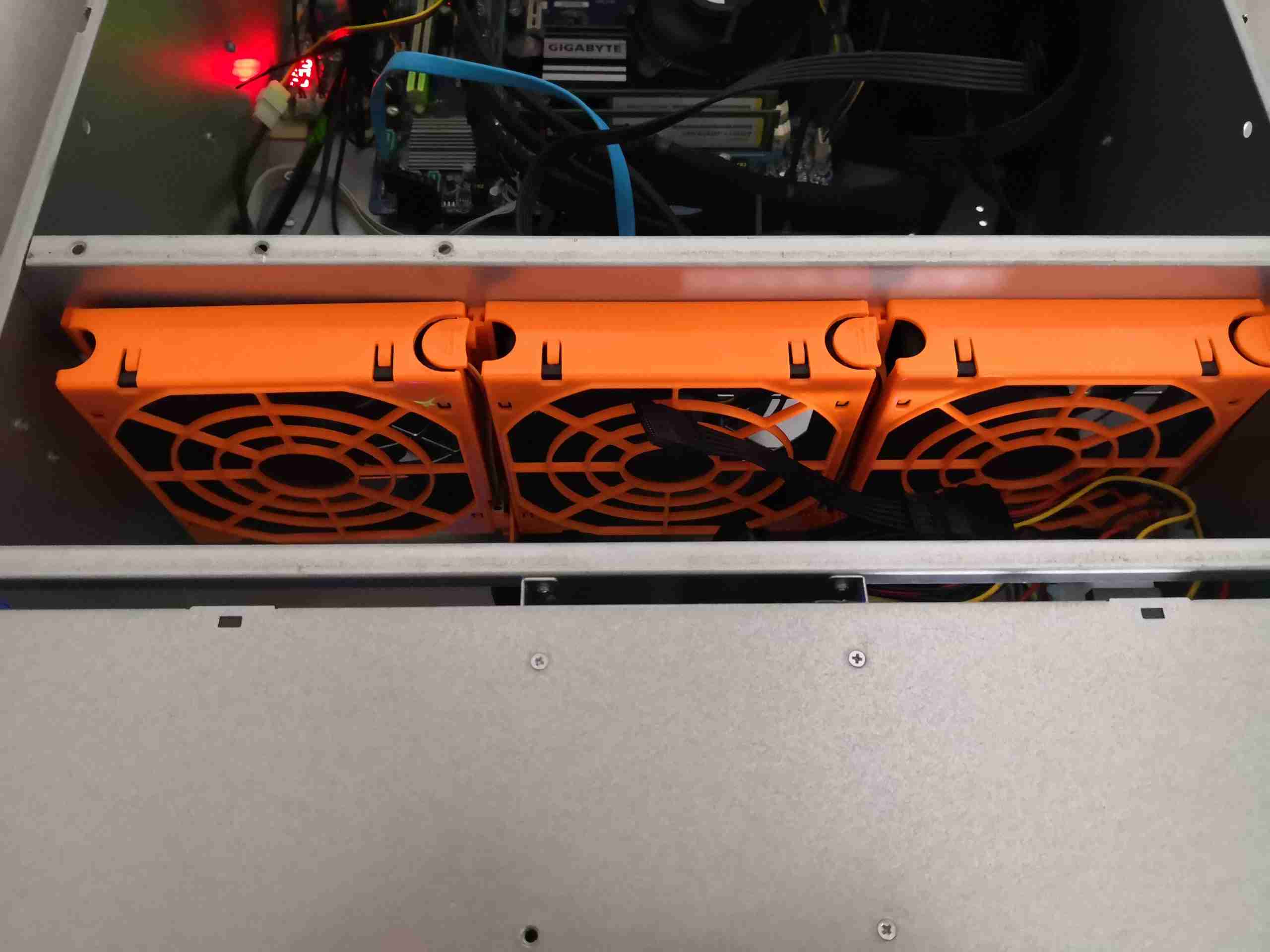
Disk Array Fan Wall
The disks are kept cool by 3x 120mm hot-swap fans on the dividing wall. These don’t create much noise, and are always at full speed.
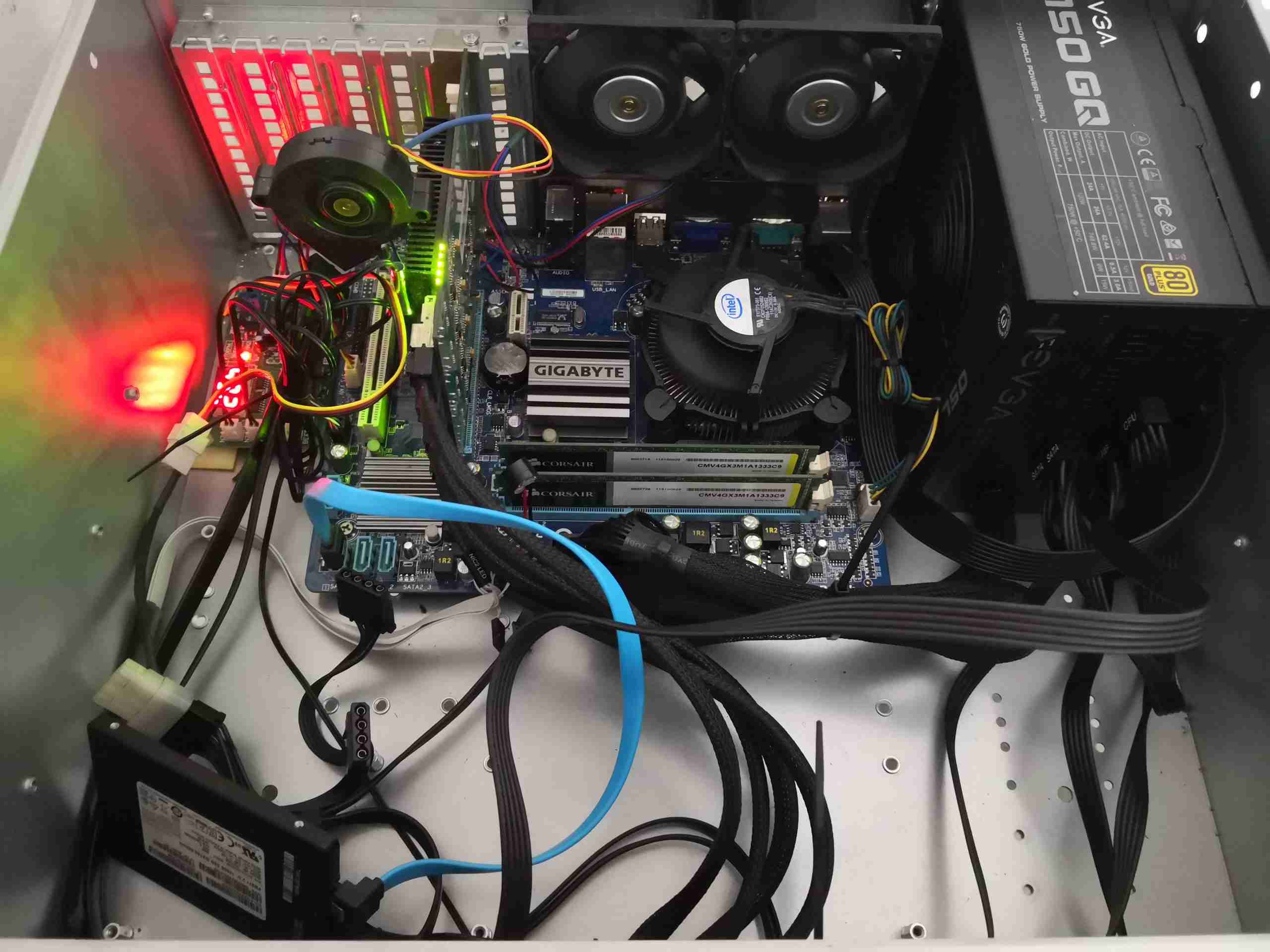
Motherboard Bay
Here’s the back of the case after transplanting the motherboard & HBA from the old chassis. There’s a new 750W EVGA modular power supply, since I’ll be expanding the disk array as well. The boot SSD is currently sat on the bottom of the case since I don’t have a data cable long enough to mount it in the proper place as yet.
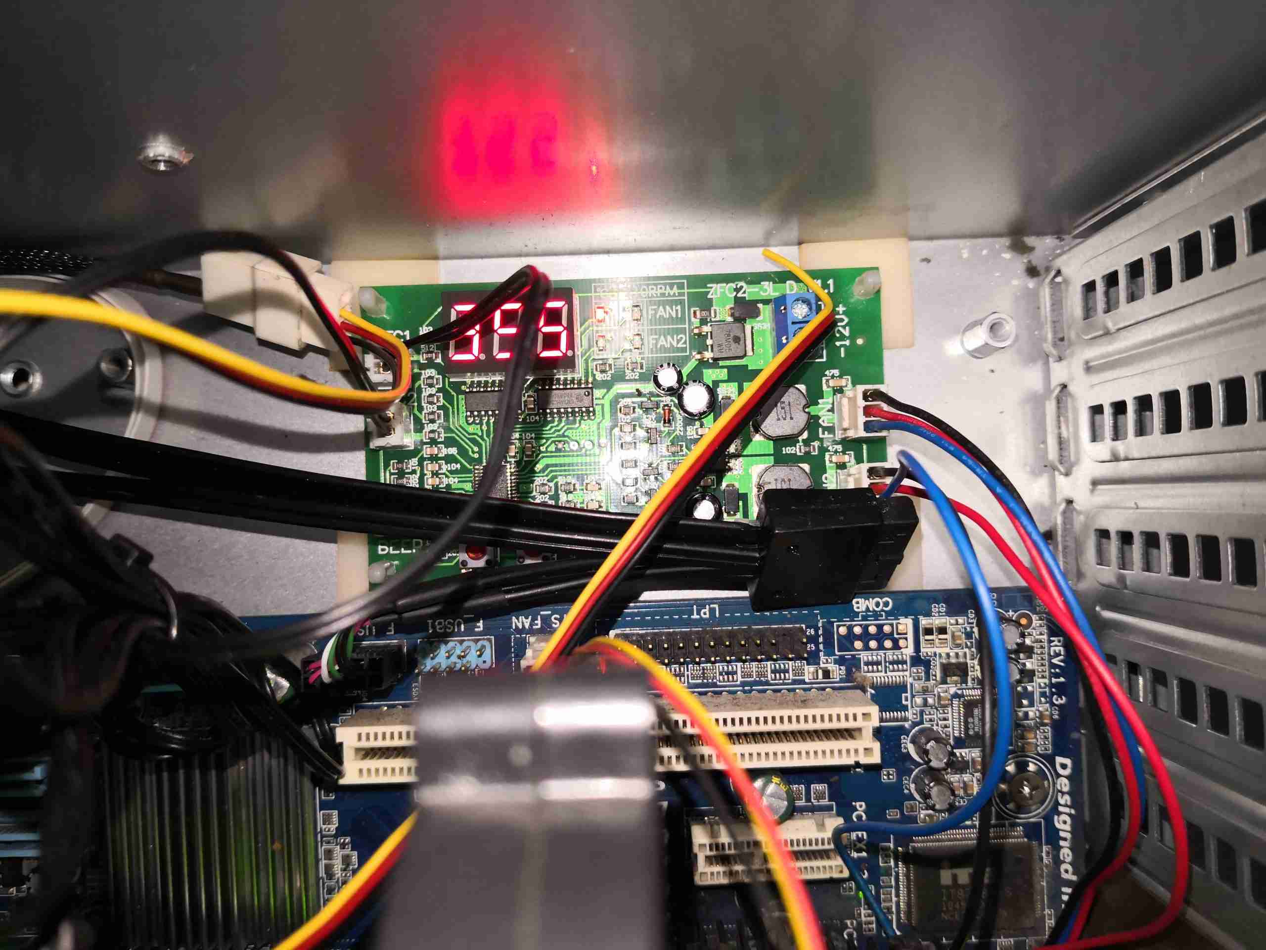
Fan Controller
Here’s the fan controller, which takes care of the dual high speed Delta fans on the back wall of the chassis. This has a pair of temperature sensors – one on the HBA card’s heatsink, and the other on the fan wall monitoring the exhaust air temp of the drive array, to control the speed of the two fans. Temperatures are kept at around 30°C at all times.
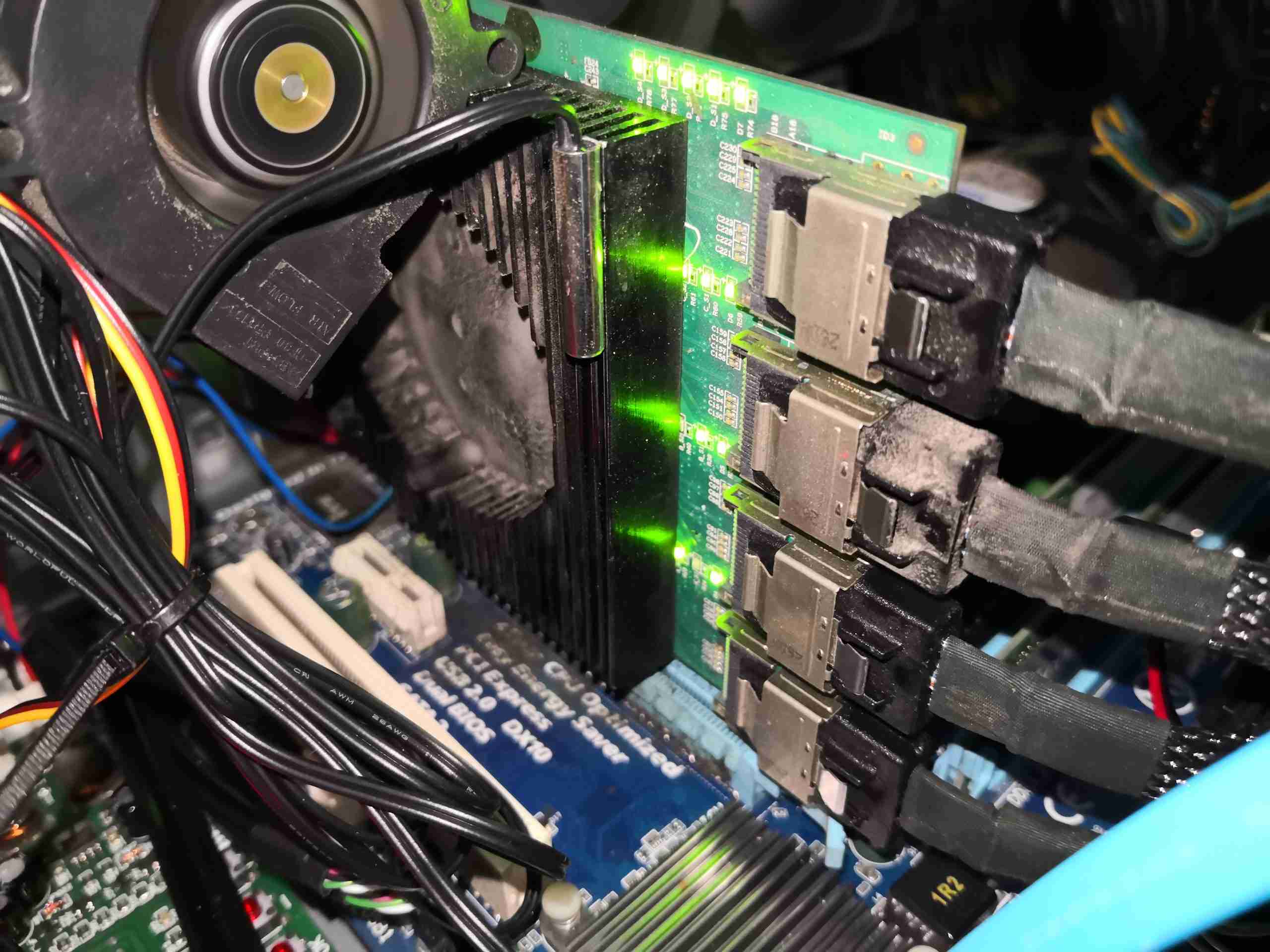
16-Port SATA HBA
Since the HBA card’s fan failed a while back, it’s had a couple of fans attached. The centrifugal one here works a little better than a massive 80mm axial fan, and is a little quieter. This is always run at full speed from a spare motherboard header. The temperature sensor feeding the fan controller can be seen here bonded to the heatsink. The 4 SFF-8087 cables are going off to the disk backplanes.
Cooling
As mentioned before, there are a pair of 80mm Delta high-speed fans on the back wall of the case, to provide some extra cooling air flow just in case overheating manages to set in. These are usually spooled down to low RPM to keep them quiet.
Since space was getting a little tight, and having some slots spare on the HBA, I decided to add some more disks to bring the active members up to 12, from 9 – increasing available disk space from 28TB to 40TB.
/dev/md0:
        Version : 1.2
  Creation Time : Wed Mar 11 16:01:01 2015
     Raid Level : raid6
     Array Size : 39068874880 (37258.98 GiB 40006.53 GB)
  Used Dev Size : 3906887488 (3725.90 GiB 4000.65 GB)
   Raid Devices : 12
  Total Devices : 13
    Persistence : Superblock is persistent

  Intent Bitmap : Internal

    Update Time : Mon Nov 18 14:13:35 2019
          State : active
 Active Devices : 12
Working Devices : 13
 Failed Devices : 0
  Spare Devices : 1

         Layout : left-symmetric
     Chunk Size : 64K

           Name : Main-PC:0
           UUID : 266632b8:2a8a3dd3:33ce0366:0b35fad9
         Events : 1653174

    Number   Major   Minor   RaidDevice State
      16       8      144        0      active sync   /dev/sdj
      11       8      160        1      active sync   /dev/sdk
       9       8      176        2      active sync   /dev/sdl
      10       8      208        3      active sync   /dev/sdn
      15       8      192        4      active sync   /dev/sdm
       5       8      112        5      active sync   /dev/sdh
       6       8       80        6      active sync   /dev/sdf
      13       8       96        7      active sync   /dev/sdg
       8       8       64        8      active sync   /dev/sde
      19       8        0        9      active sync   /dev/sda
      18       8       48       10      active sync   /dev/sdd
      17       8      128       11      active sync   /dev/sdi

      12       8       16        -      spare   /dev/sdb
The space expansion improves things there, I will be adding a couple more spare disks to bring the number up to the full 16, just in case of any failures.
There are still a couple of issues with this setup:
The motherboard & CPU are ancient. Currently an Intel Core 2 Quad, running 8GB of RAM, limits data throughput, and critically, the speed of mdadm data checks & rebuilds. The Core 2 Quad also runs at roughly the same temperature as the Sun’s core when under high load.
The SATA HBA is running 4 controllers on an expander, through a PCIe x4 link, which is a little slow due to congestion on the expander itself. RAID6 does have some write-speed penalties though.
These are issues I will address shortly, with a replacement motherboard on the way!
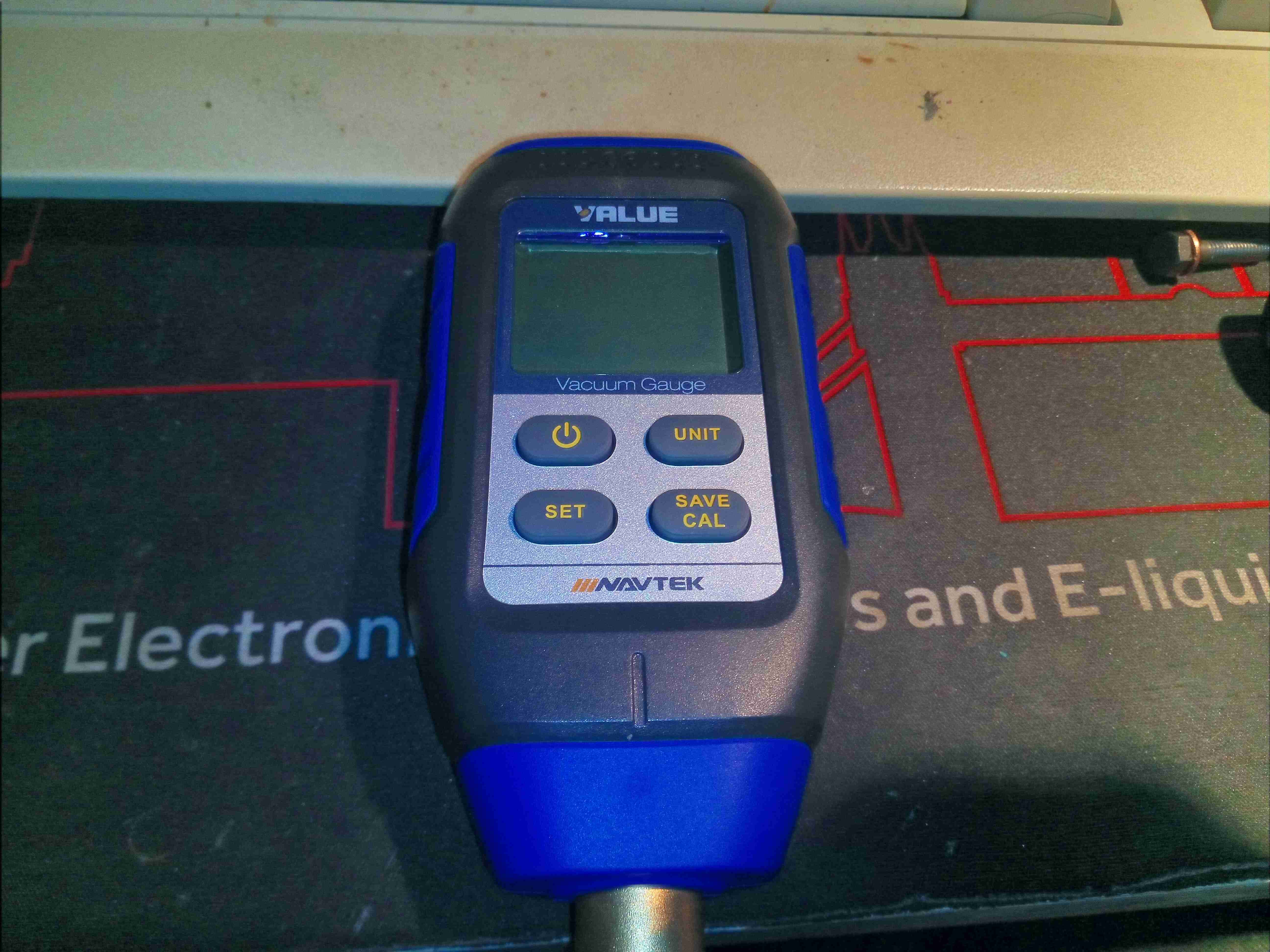
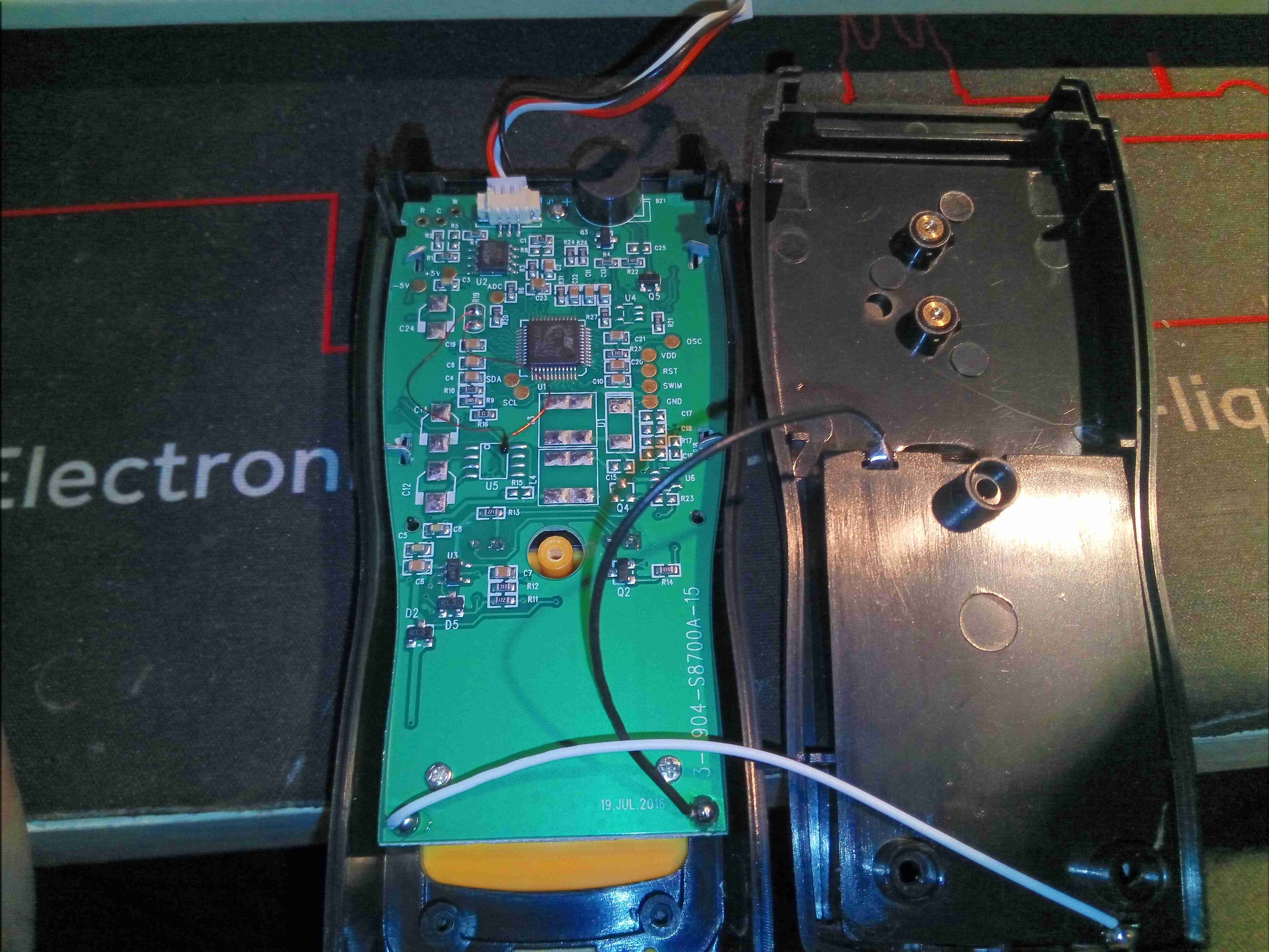
Time for another tool teardown! Here’s a VMV-1 Vacuum gauge, for refrigeration system service use. This unit will measure in Pa, millibar, mmHg & InHg, displaying it’s reading on a nice backlit LCD. Power is provided by a trio of AA cells.
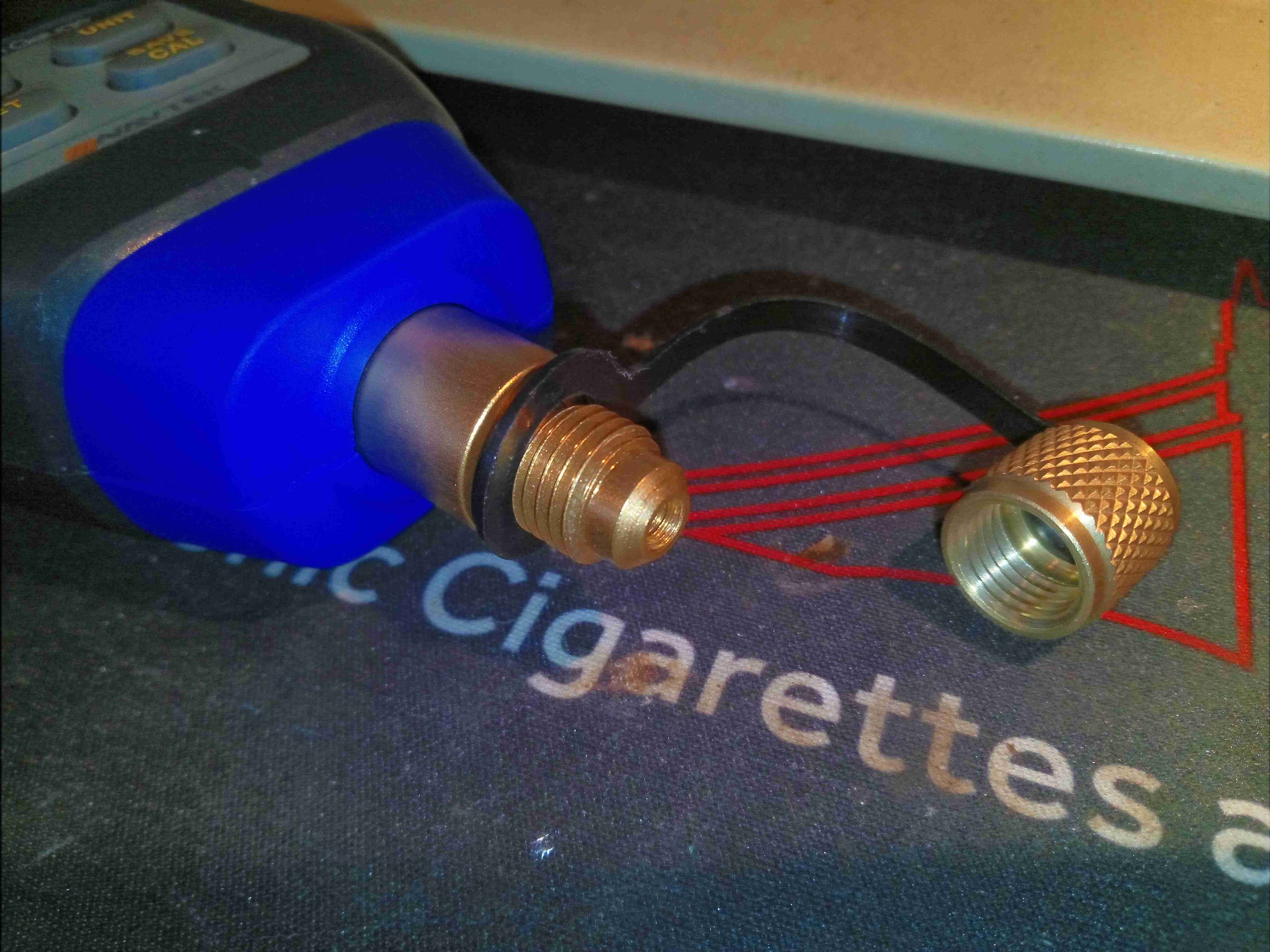
1/4″ SAE Flare Fitting
The brass fitting at the end of the unit holds the 1/4″ SAE flare port for attaching to the system under service.
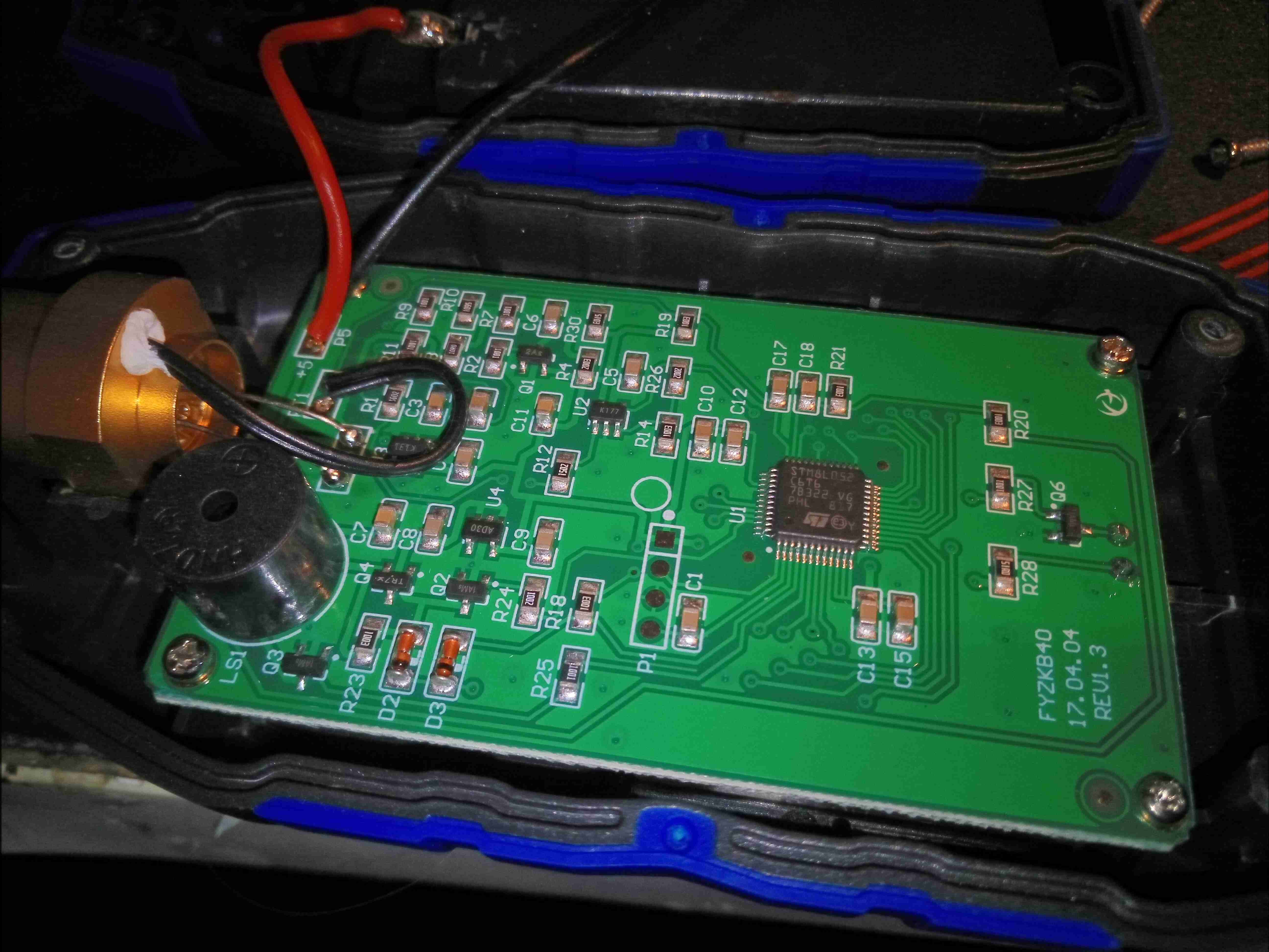
Main PCB
Removing 4 screws on the back allows the casing to come apart. Some quite simple circuitry in this unit. There’s the usual STM8 microcontroller which is very popular with the Chinese manufacturers, a beeper, along with some passives & support components. The vacuum sensor is on the left.
Vacuum Sensor
Here’s the brass block that houses the vacuum sensor itself. According to the manufacturer, this is a Pirani sensor, but I have no way to confirm without destruction of the unit. There’s a built in temperature sensor in the brass block, and the front end of the circuitry is (assuming my decoding of the SOT-23 component markings is correct!) taken care of by a TS507 precision R2R Op-Amp. There’s also a TSX561 micropower wide-bandwidth Op-Amp, along with an LD39020 LDO linear regulator for power supply functions.
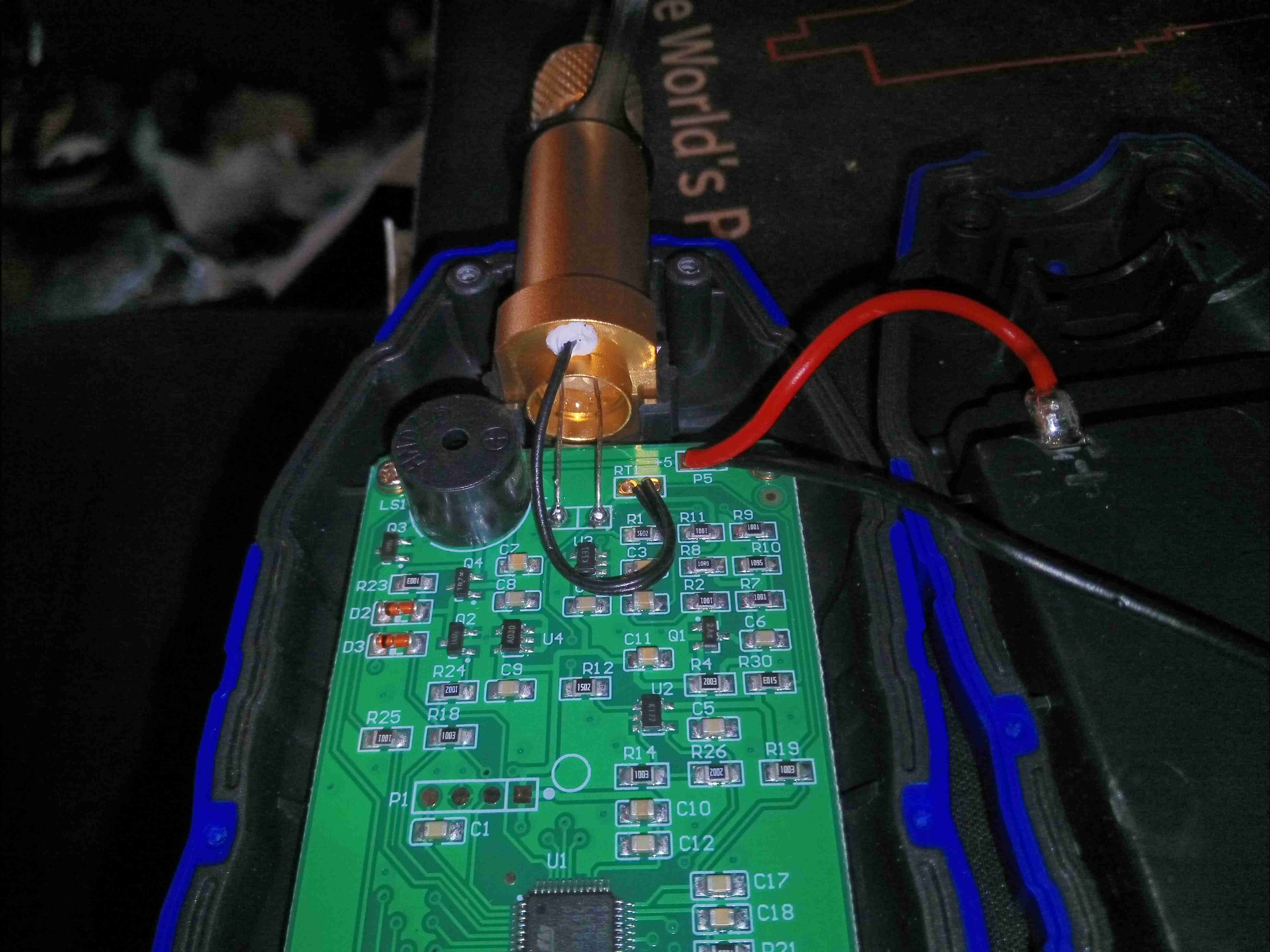
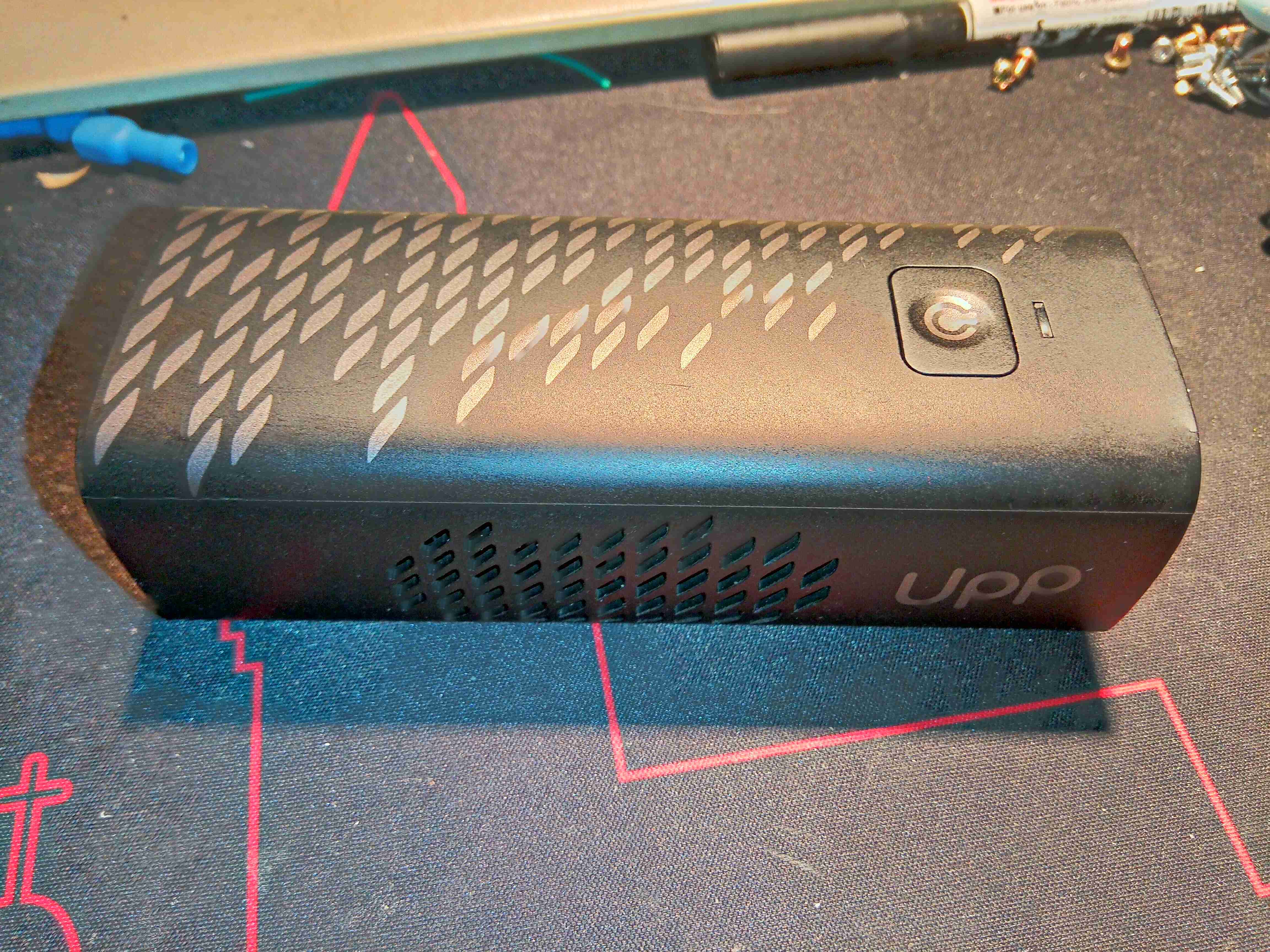
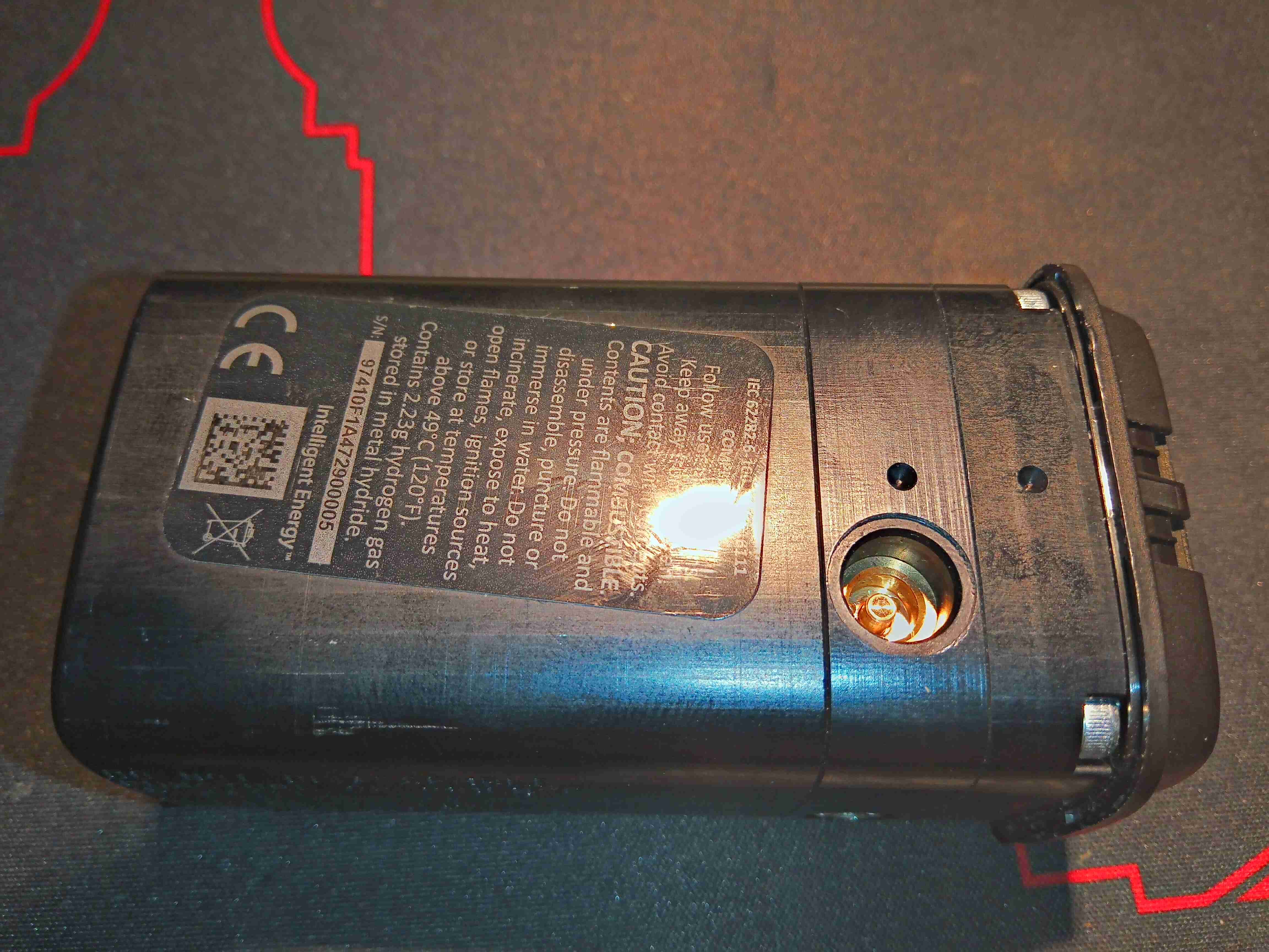
After watching Mike’s Electric Stuff’s video on these a while back, I figured it was time to grab one from eBay & see for myself how pointless a tech these are. As far as I am aware, these units are no longer available, the domain name redirects to a company site with no mention of them, and getting cartridges refilled might not be possible without some DIY engineering. These are a small portable Hydrogen-powered PEM (Proton Exchange Membrane) Fuel Cell unit, with a USB output port for charging mobile devices. There’s quite a few vents on the sides of this device, as there has to be an airflow through the PEM Fuel Cell itself, and the only control interface is a single button on the front of the unit.
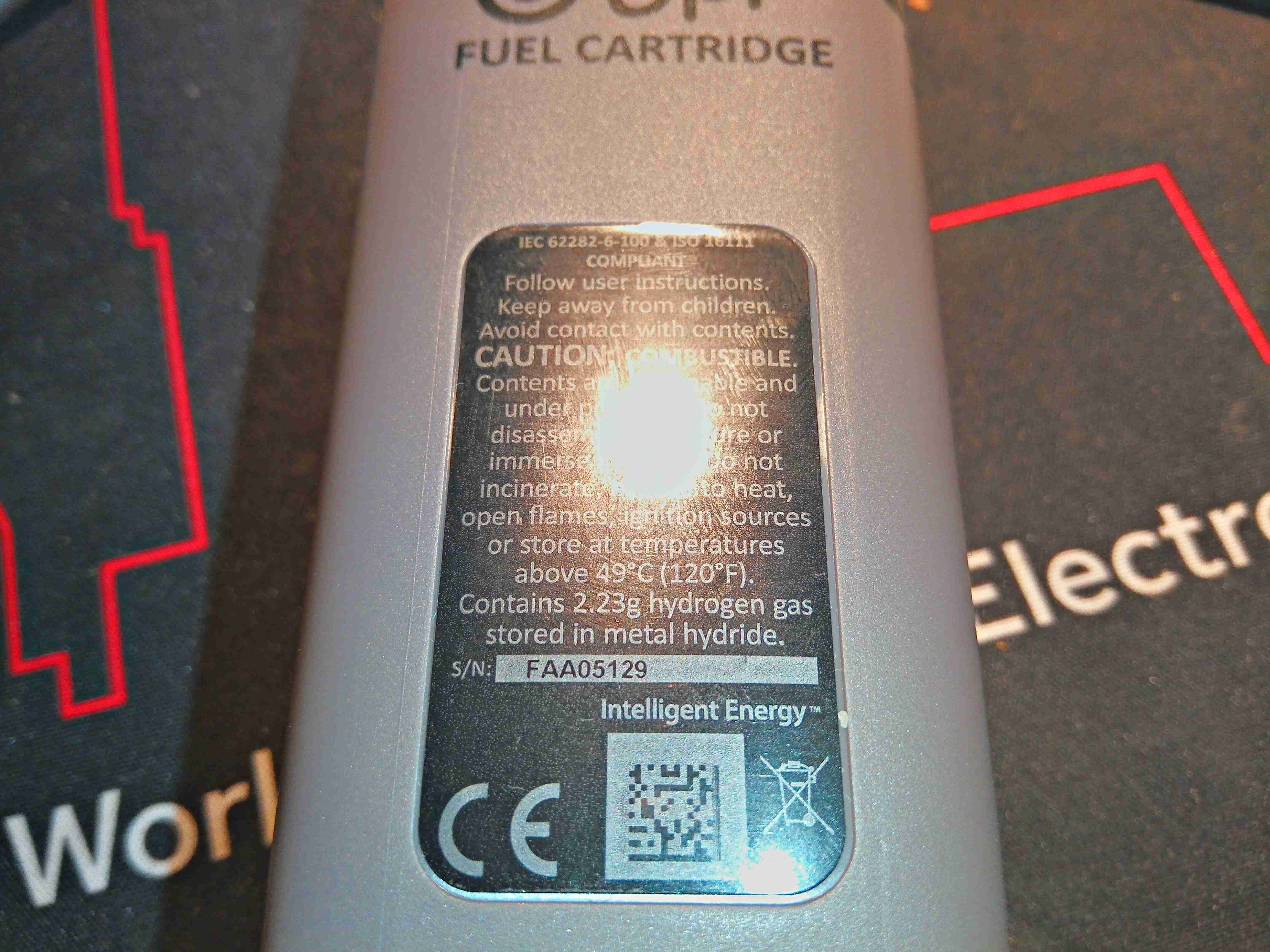
Gas Cartridge
The Hydrogen gas is stored in a cartridge, filled with Hydralloy C5 metal hydride powder. These would be exchanged for a full one when all the gas has been used, at a cost of about £6. (Extra cartridges apparently cost about £50!).
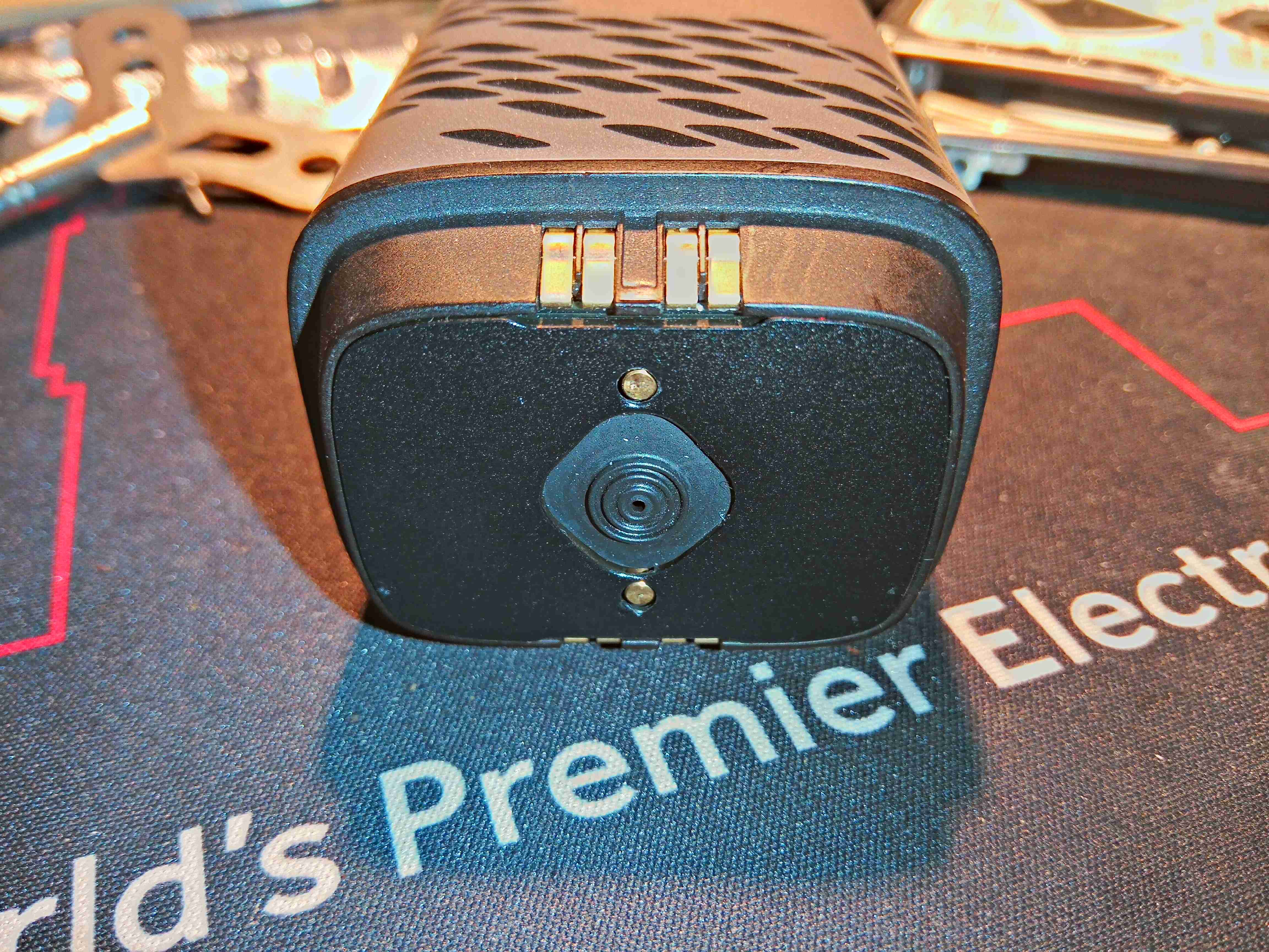
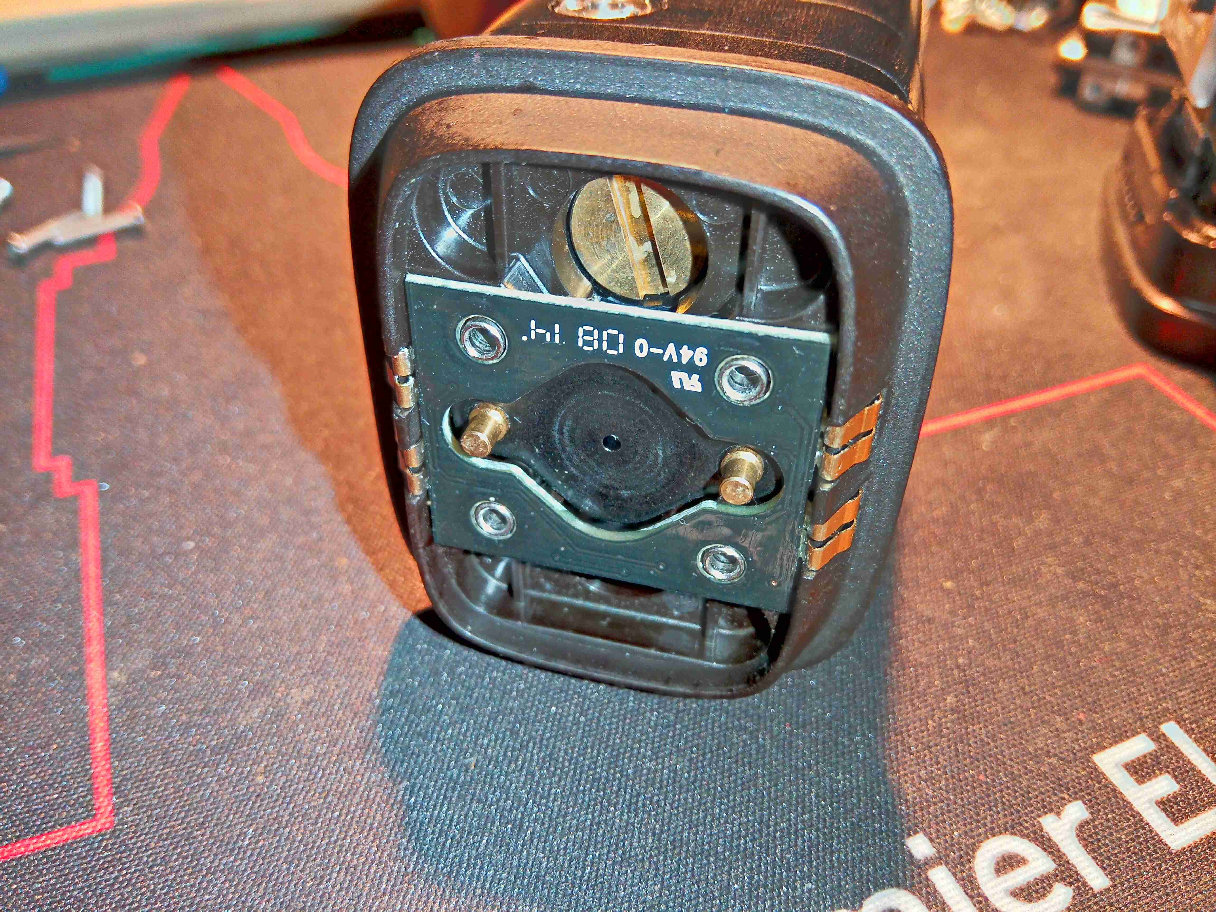
Cartridge Valve
The top of the cartridge holds the main valve, and some contacts. The gas is permitted to flow from the storage hydride by means of the two brass pins on either side of the seal – when these are both pushed down by pins moulded into the bottom of the main fuel cell unit, the internal valve is opened. The contacts connect to an internal PCB with a single EEPROM.
Cartridge Magnets
The cartridge is attached to the fuel cell with magnets – there are a pair of very powerful NdFeB magnets behind the main steel plate on the top, and a matching pair inside the bottom of the fuel cell assembly.
Cartridge EEPROM PCB
Removing a label allows access to 4 screws, which hold the top assembly onto the pressure vessel section of the gas cartridge. Here is the internal PCB with it’s EEPROM, and the large brass screw which may be for regulating the gas flow rate.
Gas Cartridge EEPROM
Removing the PCB allows us to see the EEPROM itself – a 2kBit part, which contains information like remaining gas charge, and serial number. When the cartridge reads empty according to this EEPROM, the cell will stop functioning. Luckily however, it is happy to operate without this PCB even being present – I expected the unit to spit & error & shut down if it couldn’t communicate over the I²C bus with this memory.
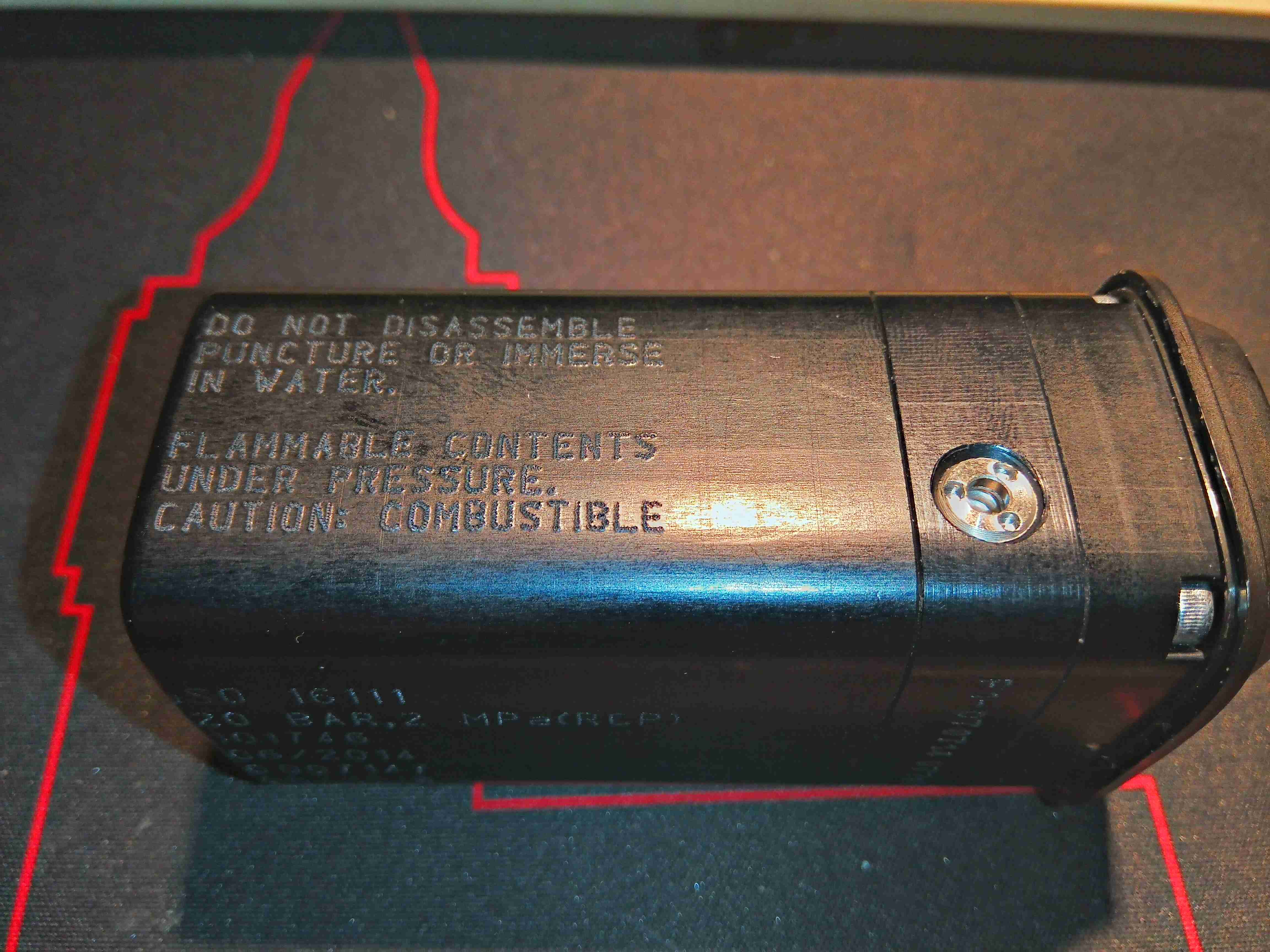
Pressure Relief Valve
Removing a screw in the base of the casing (hidden under a label) allows the plastic shell to come off, revealing the aluminium pressure containment to be seen. There’s a pressure relief valve on the side here, and some warnings about what not to do with the thing.
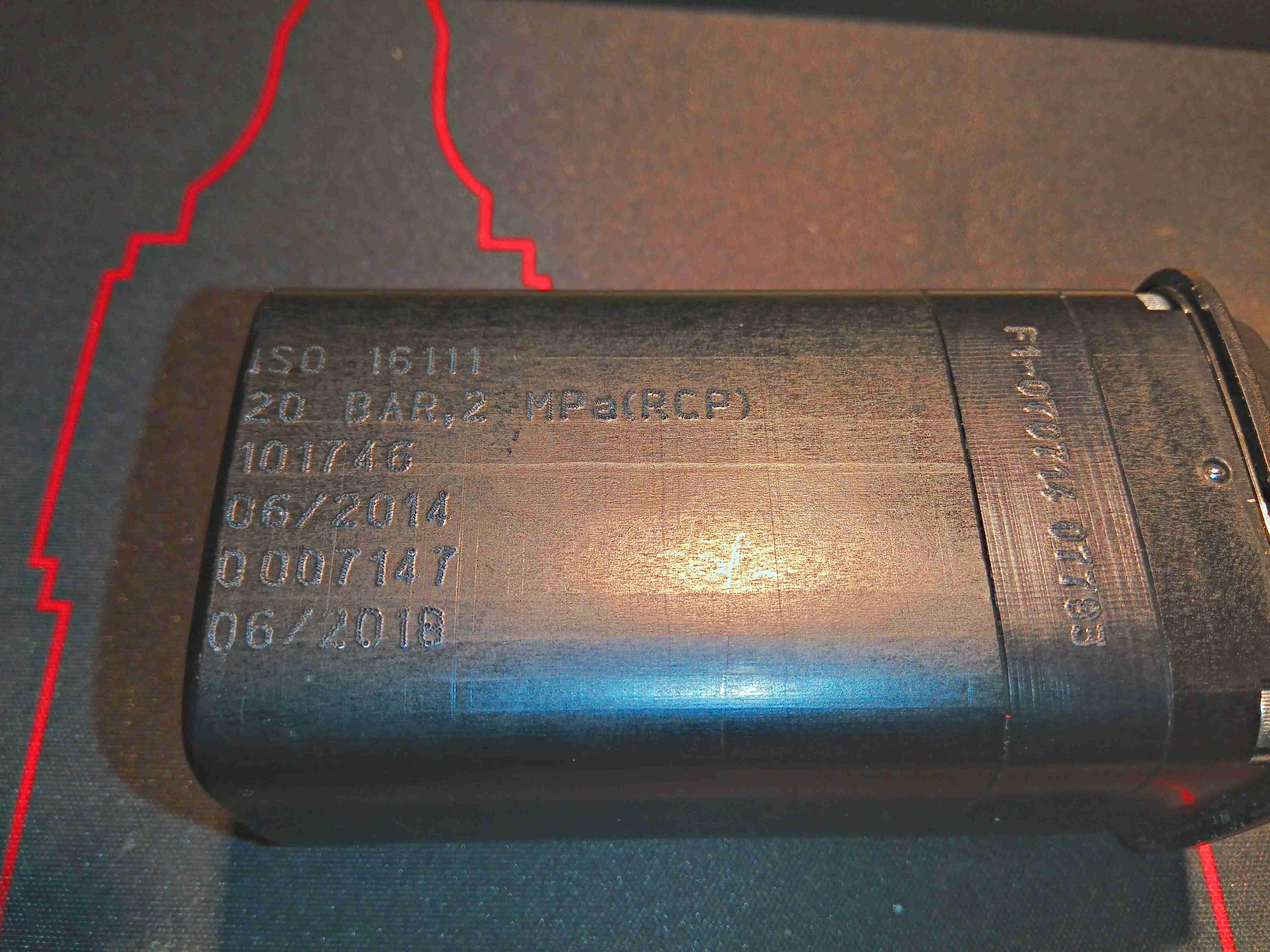
Pressure Vessel Info
Some more info on the other side, with the ISO standard this cell is rated to, and the 20 bar Rated Charging Pressure. There is also a stamp indicating how long the certification of the vessel lasts. This one is rather out of date…
Charging Valve
The opposite side of the unit has another label covered in warnings, and a recessed charging valve. It’s an interesting one this – there are no threads, just a brass valve with a depressable pin in the centre to allow the gas to flow. Since this needs to be charged at 20 bar, a special jig would be required, to hold any charging adaptor in place while the gas is injected. There’s no chance of getting the official part for connecting to this, so I intend to machine a brass adaptor to connect here for charging.
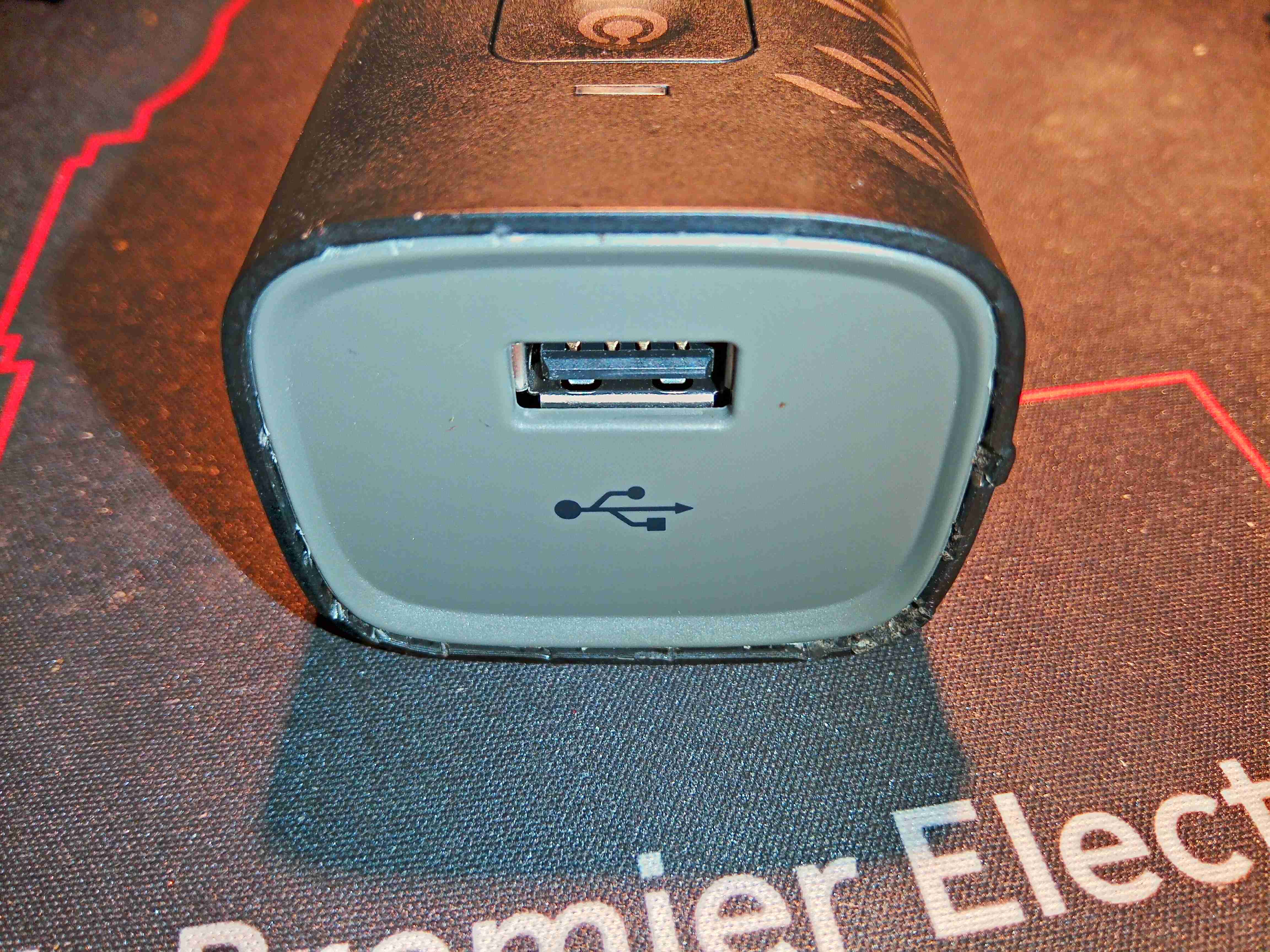
USB End
The top end of the fuel cell unit has a single USB port, rated to 1A according to the rating plate:
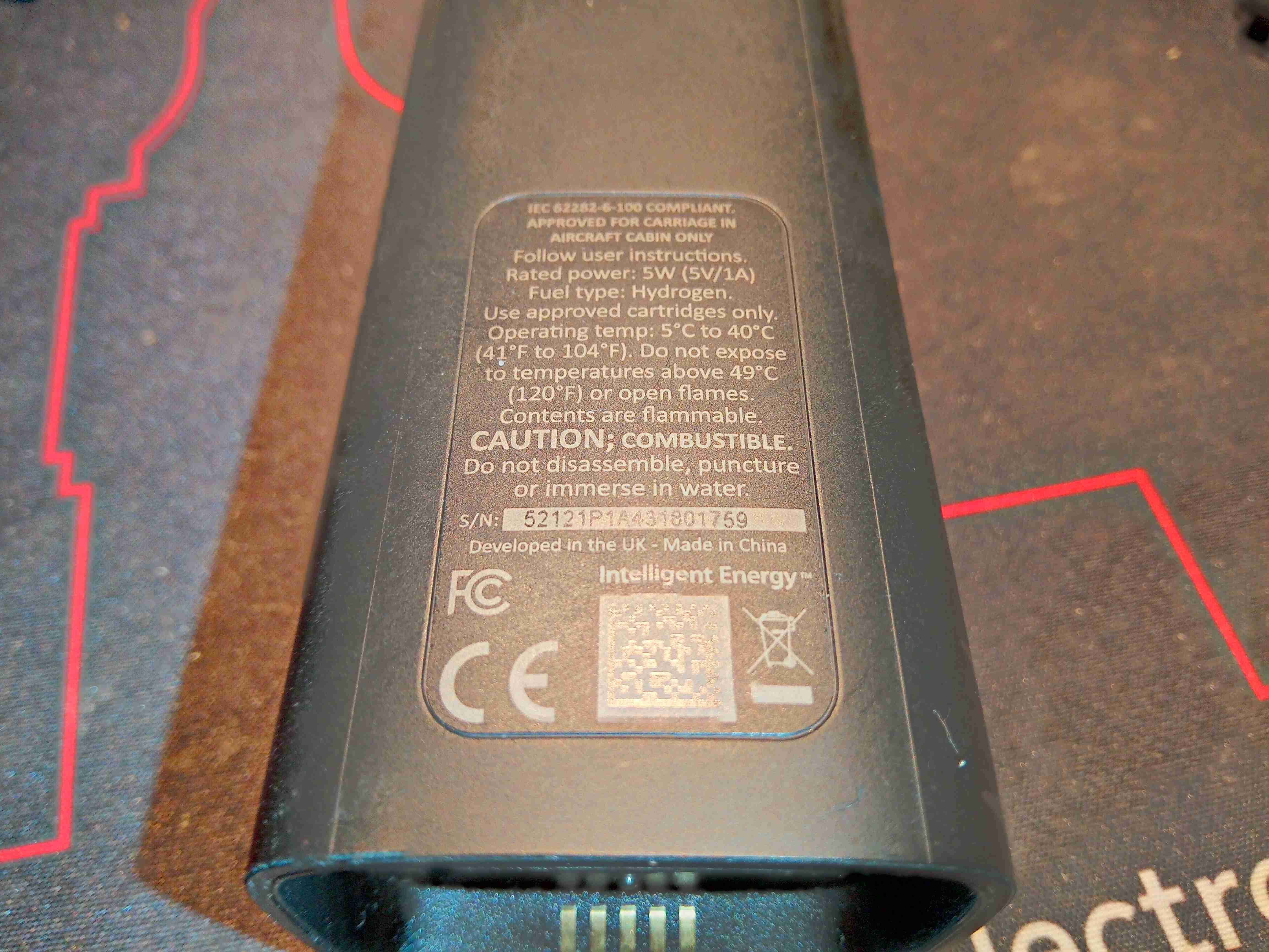
Rating Plate
Standard rating plate with some regulatory markings, and output power.
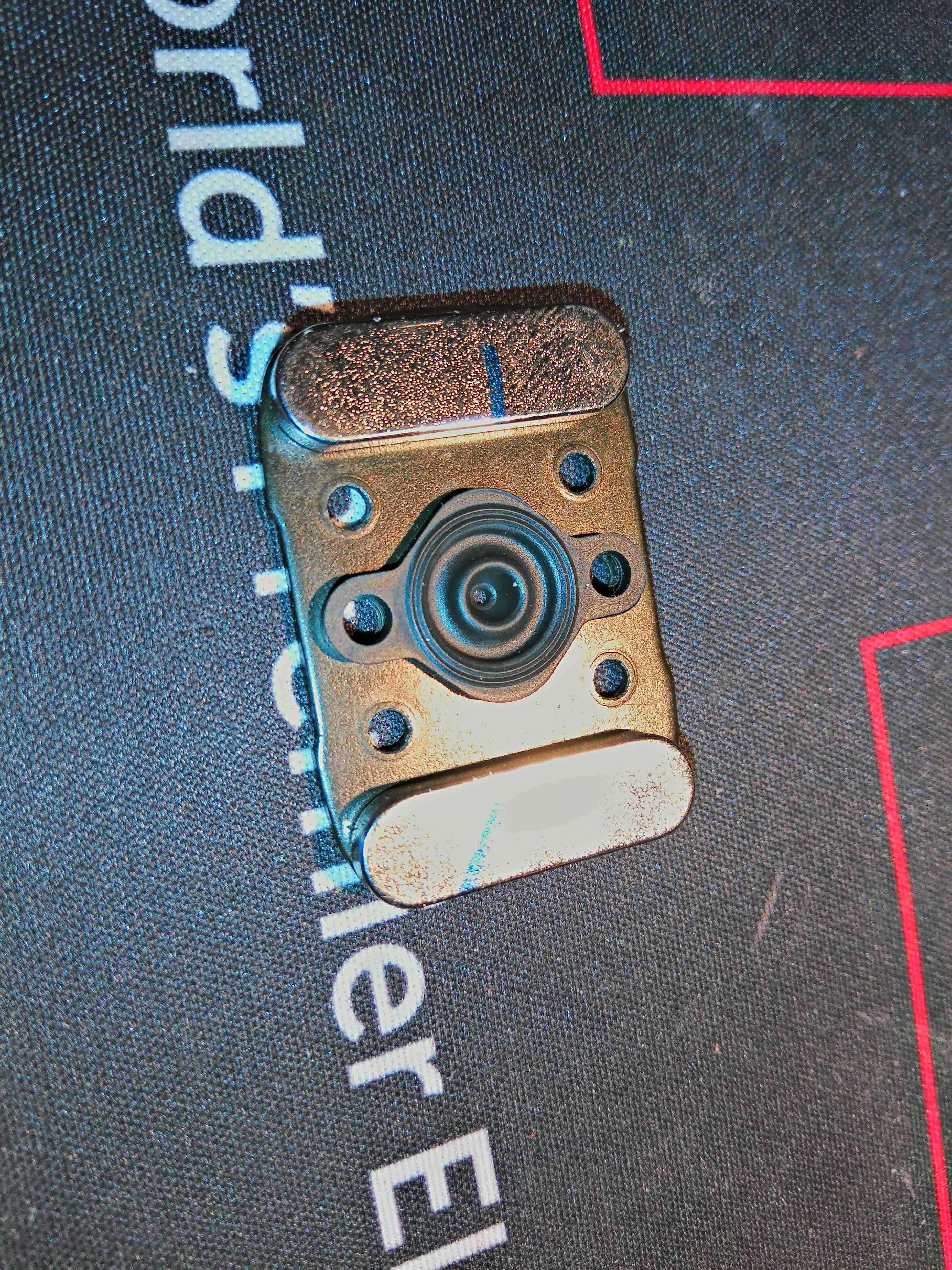
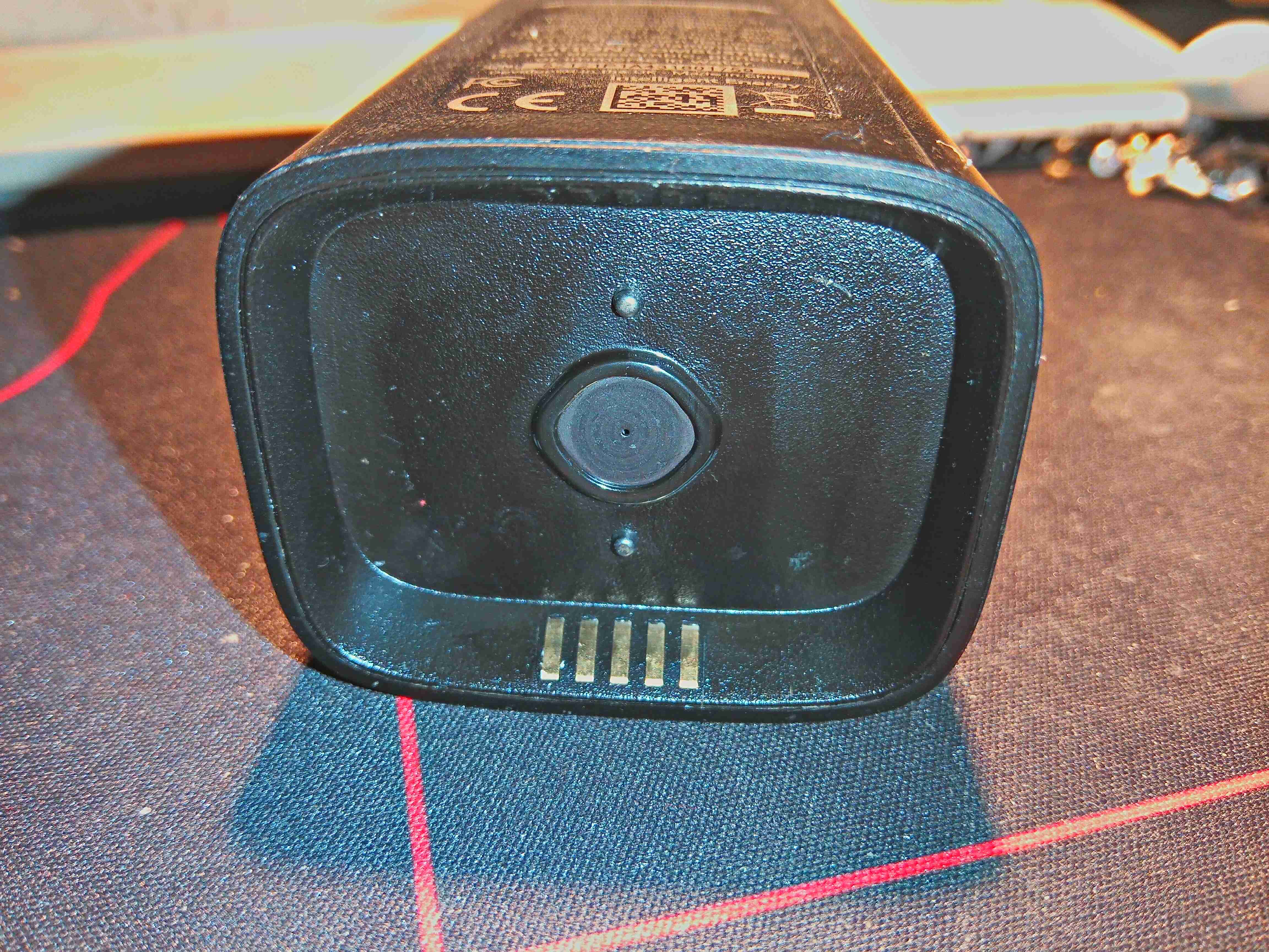
Gas Inlet
Here is the bottom of the fuel cell unit, which magnetically couples with the gas cartridge. The two pins either side of the gas port are visible, and it is these which open the valve on the cartridge. The 5 gold-plated contacts at the edge make contact with the spring terminals on the EEPROM PCB on the gas cartridge for communications. They are also used with a separate base for external charging of the LiPo cell contained inside. More on this later.
Internal Frame
The main body of the cell is secured together with internal clips – and are not intended to ever be opened without damage, but here is the core of the unit. There’s a large Lithium Polymer cell on the top of the main board, which is required to actually get the unit going in the first place. I suspect this is also used to buffer the output from the PEM cell itself, and provide the maximum of 1A output current. (My unit would not charge a device even at 500mA when it arrived, until the internal cell was charged up – a red LED was lit just before the unit shut itself down).
USB Output
The top of the board has the single user button & the USB port. This port is enabled for communications – there used to be an app for phones that would show some statistics about the unit to the user.
PEM Fuel Cell Connections
Turning the unit over shows the PEM Fuel Cell itself, a stack of 5 plates in series. There are 5 connections into the cell unit – main power output terminals, and a pair of terminals for a thermistor, which is buried right in the centre of the cell at the top, to measure operating temperature.
Cooling Fans
The other side of the frame holds two tiny fans, which waft some air through the channels in the fuel cell plates. This will both be for cooling, and to ensure that Oxygen can get into cell assembly to react with the incoming hydrogen.
Fuel Cell Frame
The fuel cell unit clips off the top of the main frame, exposing the two gas control valves. The one on the left regulates the gas input from the cartridge, while the one of the right is regulating the gas outlet to atmosphere. There is also the port of a pressure sensor popping up to the left of this outlet valve.
Fuel Cell Gas Ports
Here’s the bottom of the fuel cell module, with a pair of rubber seals on the gas ports, which interface with the faces of the valves. The H² gas inlet port is on the left.
Bare PEM Cell
Some more unclipping of plastic frames allows the bare module to be removed. This is a really heavy-gauge piece of steel to clamp the module together, secured by spring clips.
PEM Cell Plates
Here’s the edge of the module, showing the individual plates. There are silicone seals between them to seal the gas ports, and a thin PCB material at the top & bottom as electrical contacts. The plates being stacked together means these are all in series, providing about a 4.6v output voltage.
Cartridge Adaptor Plate
Here’s the back of the cartridge adaptor, with the pair of magnets to match the ones on the gas cartridge.
Gas Inlet
This rubber grommet seals onto the metal plate in the adaptor, sealing the gas inside. The 5 contacts are visible here to communicate with the cartridge EEPROM.
PCB Bottom
A bit of de-soldering later, and the board is free from the frame. This is very densely packed board, covered in DC-DC converters of various types. The main microcontroller is a STM32F107 from ST Micro – a 72MHz part loaded with interfaces. There’s a small WinBond EEPROM here too, which from Mike’s video, seems to be used for log data. It would be nice to get access to this board through a serial interface, to see if there’s any engineering options left in the software for some tinkering. The large inductor is part of a synchronous DC-DC converter, the controller IC for such is on the other side of the PCB.
There’s a L324A Quad Op-Amp in the top right corner of the board, next to the USB port, along with a load of discreet transistors spread throughout the board. Some of these transistors will be used for switching the solenoid coils on the gas valves. The other major part on this side of the board is the gas pressure sensor, just to the right of the EEPROM.
PCB Top
The other side of the board has even more components, the Lithium cell protection MOSFETs are at bottom left, the Synchronous DC-DC converter controller, a TPD43000 from Texas Instruments is in the centre. There are more discreet transistors on this side, for driving the solenoids & fan power control.
Control Valve Cores
Not much remains in the frame, other than the gas valves themselves.
This is an interesting piece of tech, but it’s definitely useless – especially in the era of high capacity power banks of up to roughly 40Ah. The gas cartridges that this unit eats through hold approx. 7Ah of capacity, and at £6 a pop, it is an expensive way to charge a mobile device. I will be coming up with a way of recharging the gas cartridge though, which will involve some sideways thinking & machining of brass. More to come on that!
It seems the standard of driving in the UK is dropping by the day:
This dude either really didn’t want to wait, or was blind. If this wasn’t on a 20MPH limit residential road, the result may have been a little different…
Even after he’s forced to move back to his side of the road, he tries to have a go at me for the situation. There will no doubt be more clips like this to come!
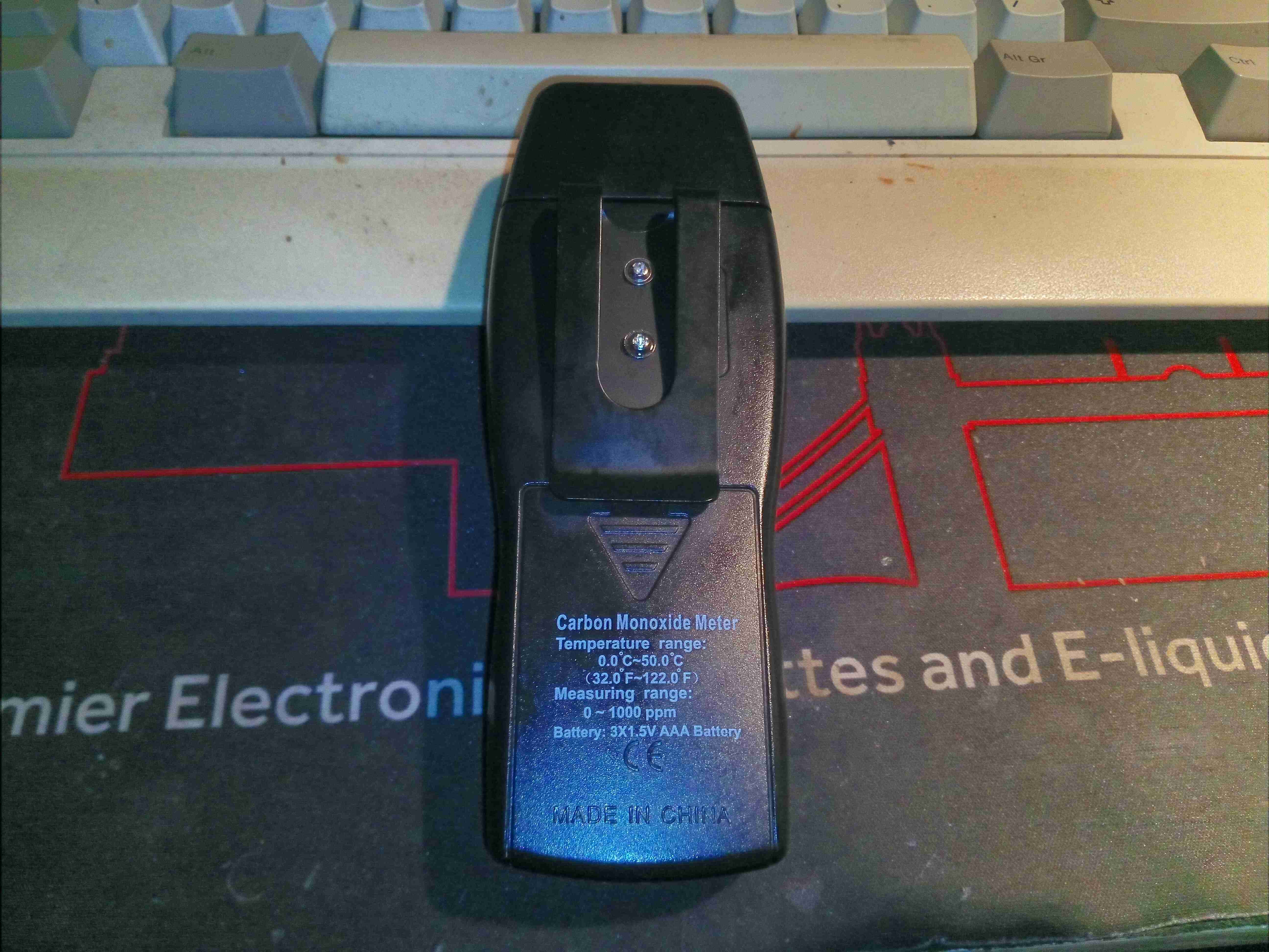
Here’s a handy tool – a Carbon Monoxide meter that range to 1000ppm, with immediate update. Very handy for checking emissions of fuel burning appliances. There’s a large LCD on the front for displaying the reading, and the ambient temperature. There is a user-settable alarm if a high concentration of CO is detected in the air, and High/Low hold modes.
Rear With Belt Clip
The rear of the unit has a belt clip, and the battery compartment which holds 3x AAA cells.
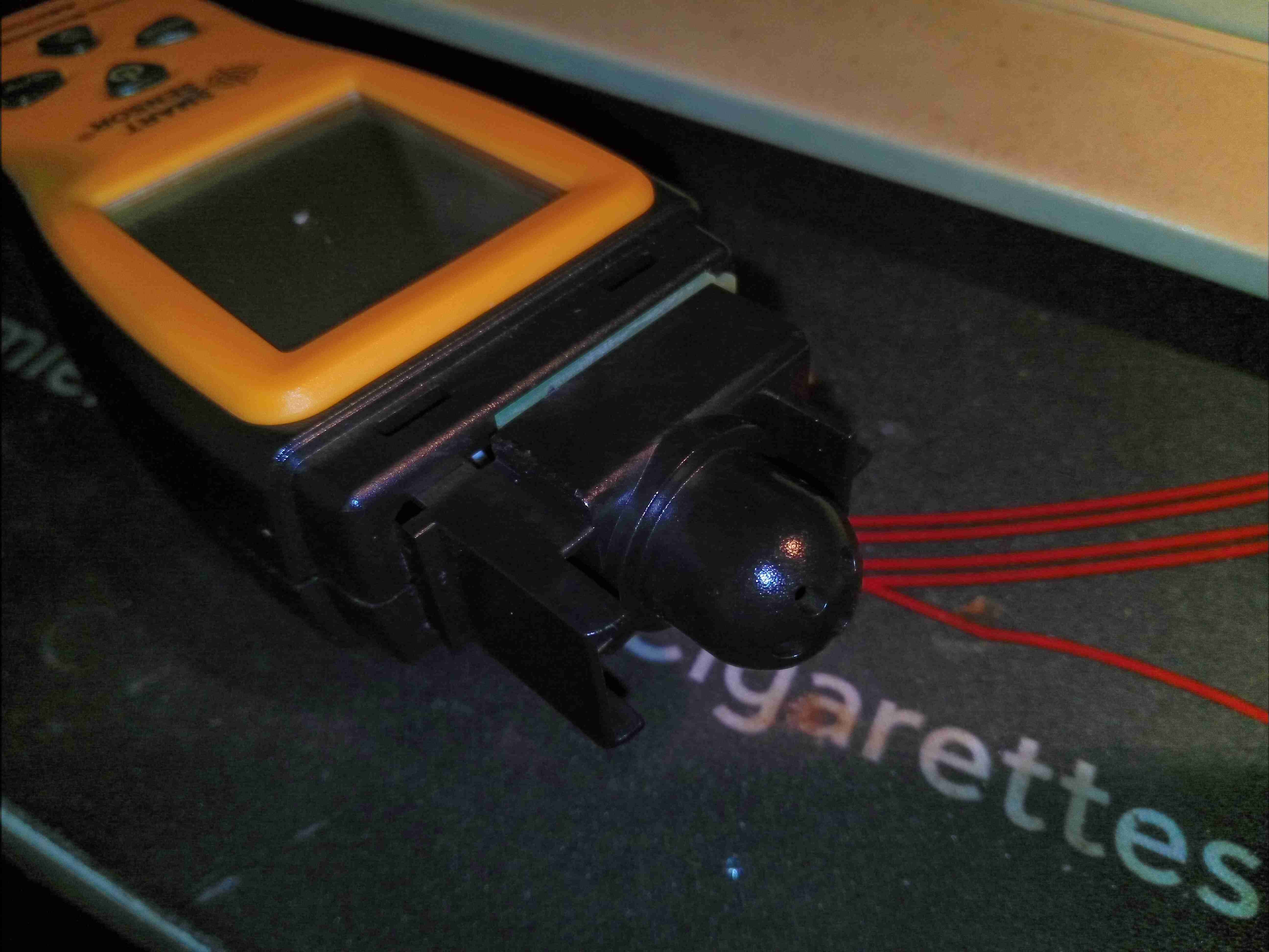
Sensor Cap
Under the decorative cap at the detector end is the sensor module itself, with a thick plastic cap covering the actual sensor.
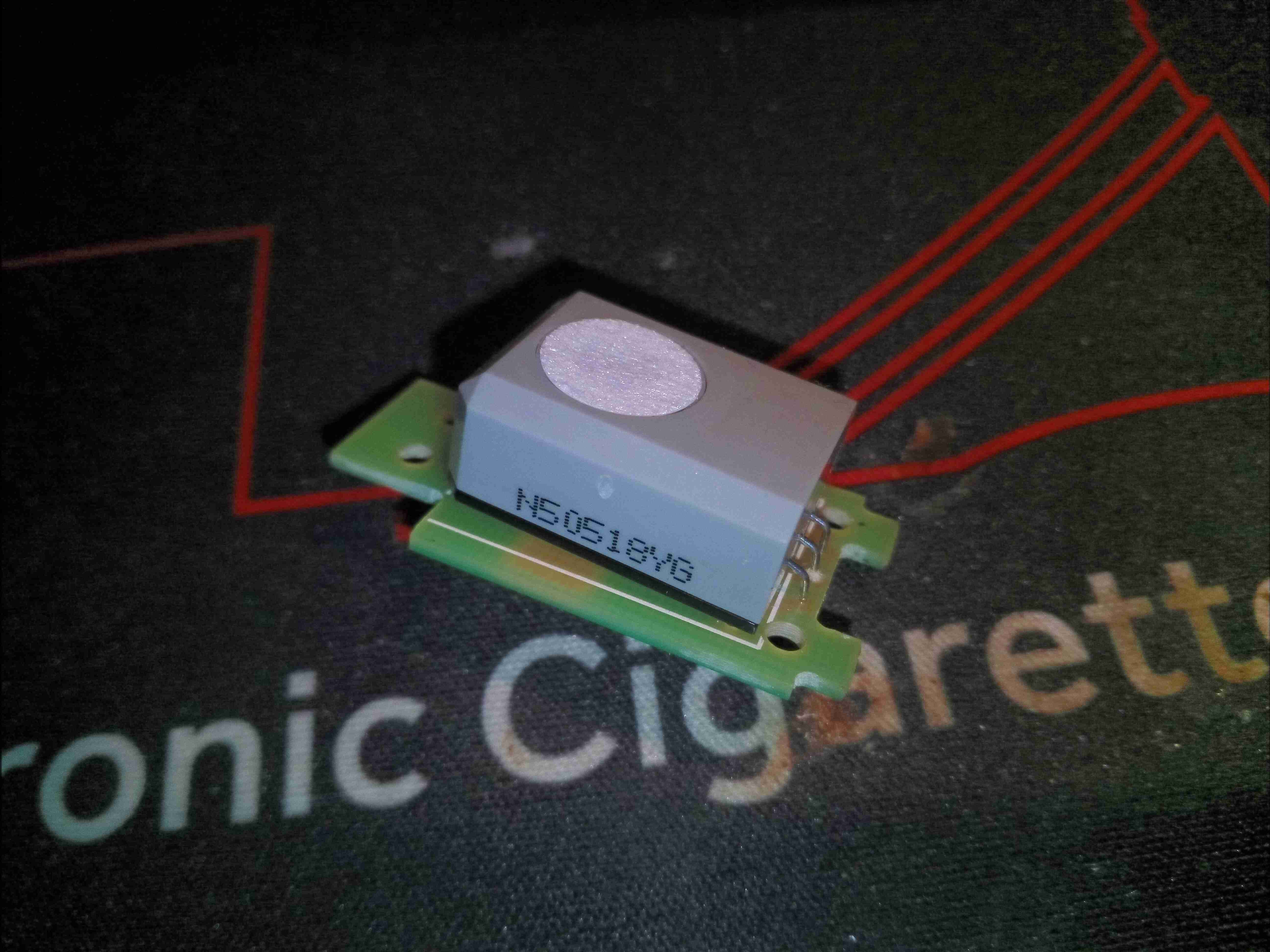
CO Sensor Cell
The CO sensor cell is one of the smallest I’ve seen, a NAP-505 from Nemoto. Easily replaceable with a soldering iron if required after the quoted 7 year lifespan.
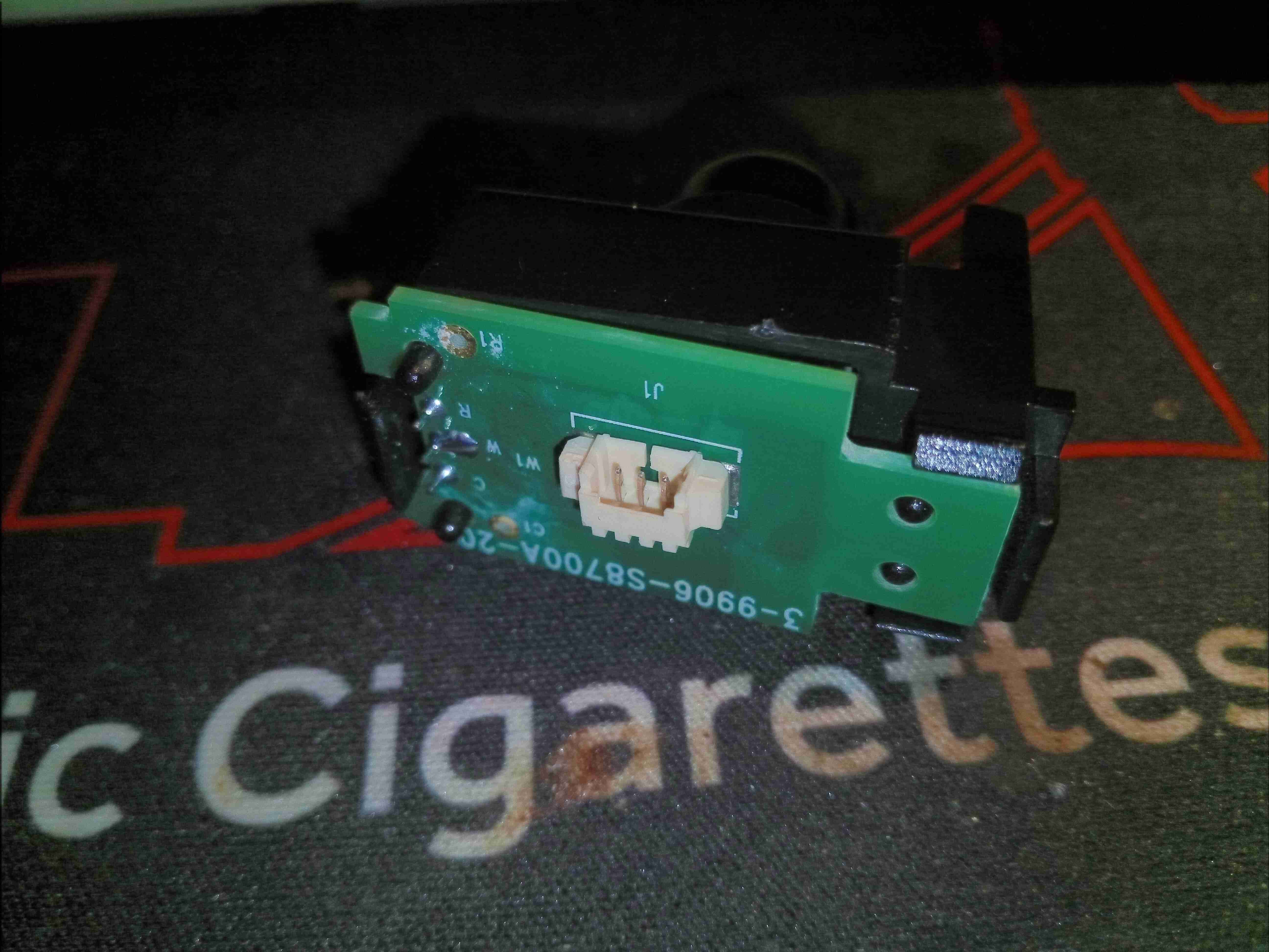
CO Sensor Module
Connections to the main PCB are done through a small 3 pin connector & wiring loom.
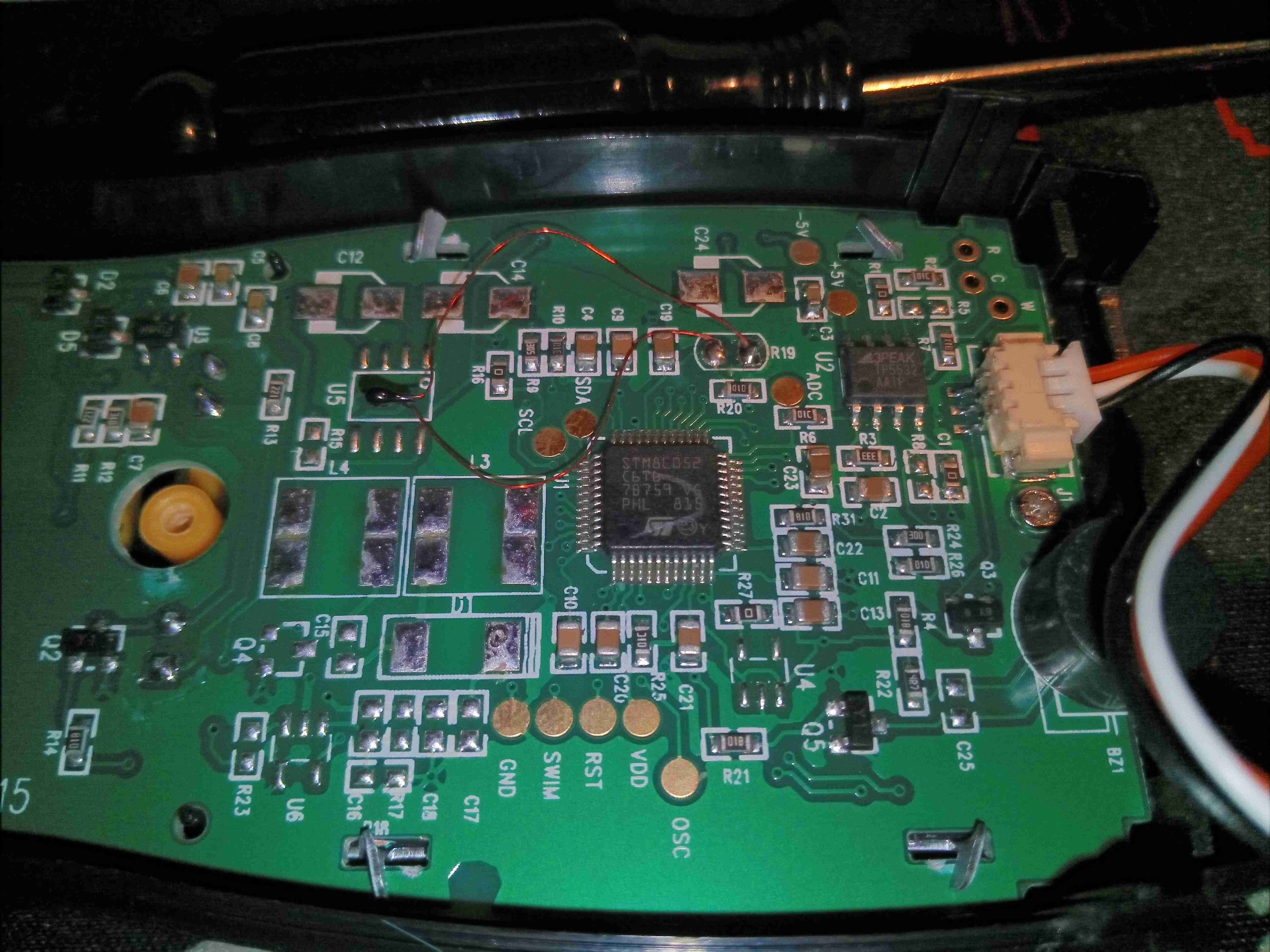
Main PCB
Removing the 3 screws from inside the battery compartment allows the back cover to be removed. The belt clip screws into a pair of brass inserts, which is a nice touch. The sensor connects to the JST connector at the top of the boat.
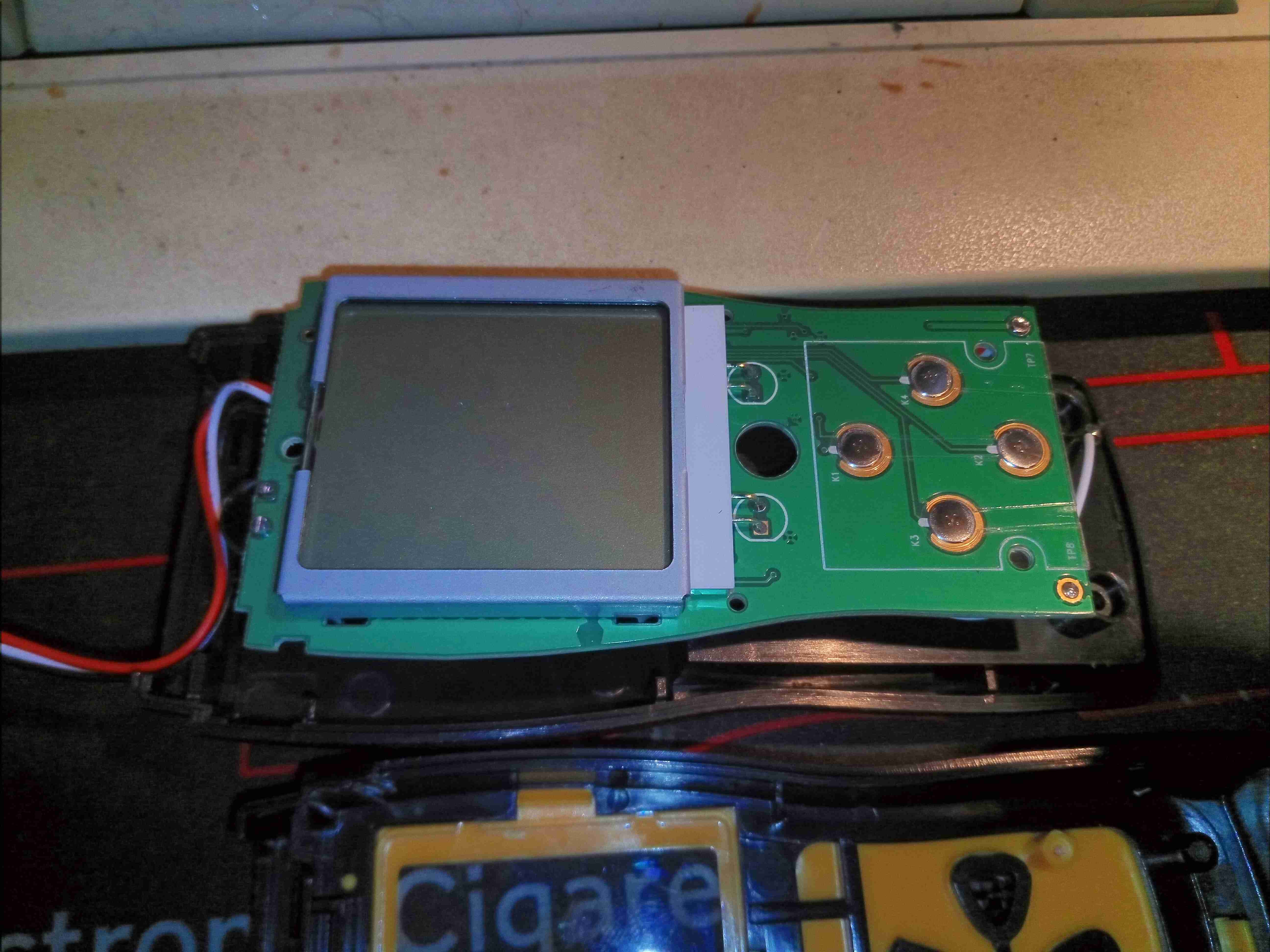
LCD
The front of the PCB has only the buttons & the LCD itself, which is backlit with a pair of green LEDs.
Microcontroller
There isn’t much to the actual circuitry. There’s an STM8 microcontroller, and a TP5532 zero-drift op-amp to deal with the sensor front end. Rather nicely, every single one of the test points is labelled! Handy for any hacking that needs to be done.
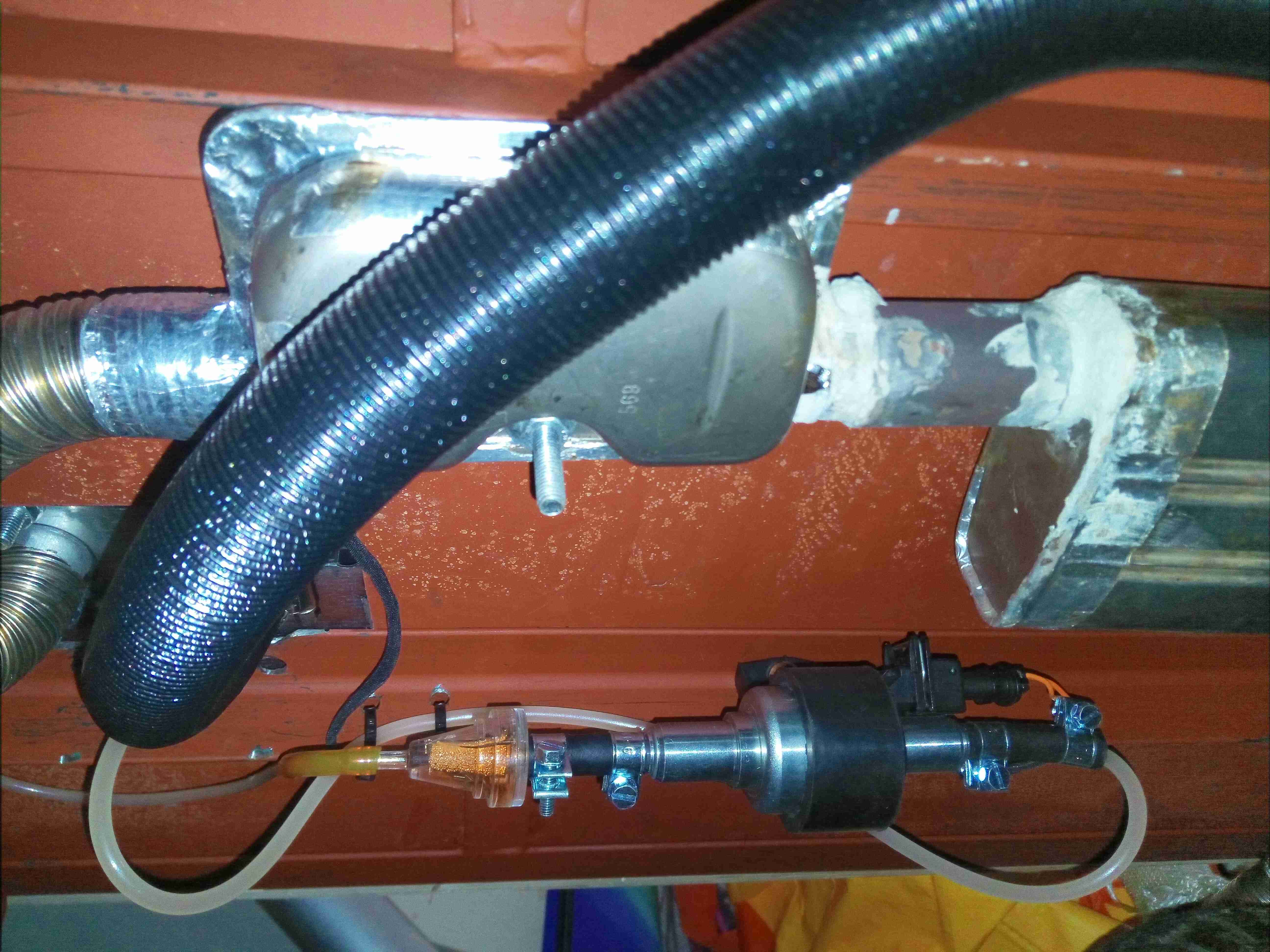
While we’re away camping, be it at a festival or general site, it would be nice to have a relatively efficient fridge to store food & drink in, so I set to work assessing the requirements. Commercially supplied 12/24v fridges are hella expensive – running between £450-£700 for even a small compressor coolbox! So in my general style, I figured it was time to get building my own, integrated into the current system. With the bonus of learning some things along the way. There are some refrigerants that aren’t covered under the F-Gas regulations, such as R600a (Isobutane) & R290 (Propane), so I can easily avoid those legal requirements, not to mention being a little more environmentally conscious. The common Danfoss BD35F compressors are designed for R-134a, but there are equivalent replacements available for the automotive AC market that operate within the same pressure ranges. As far as I can tell, these replacements are mixtures of R600a & R290 in various proportions.
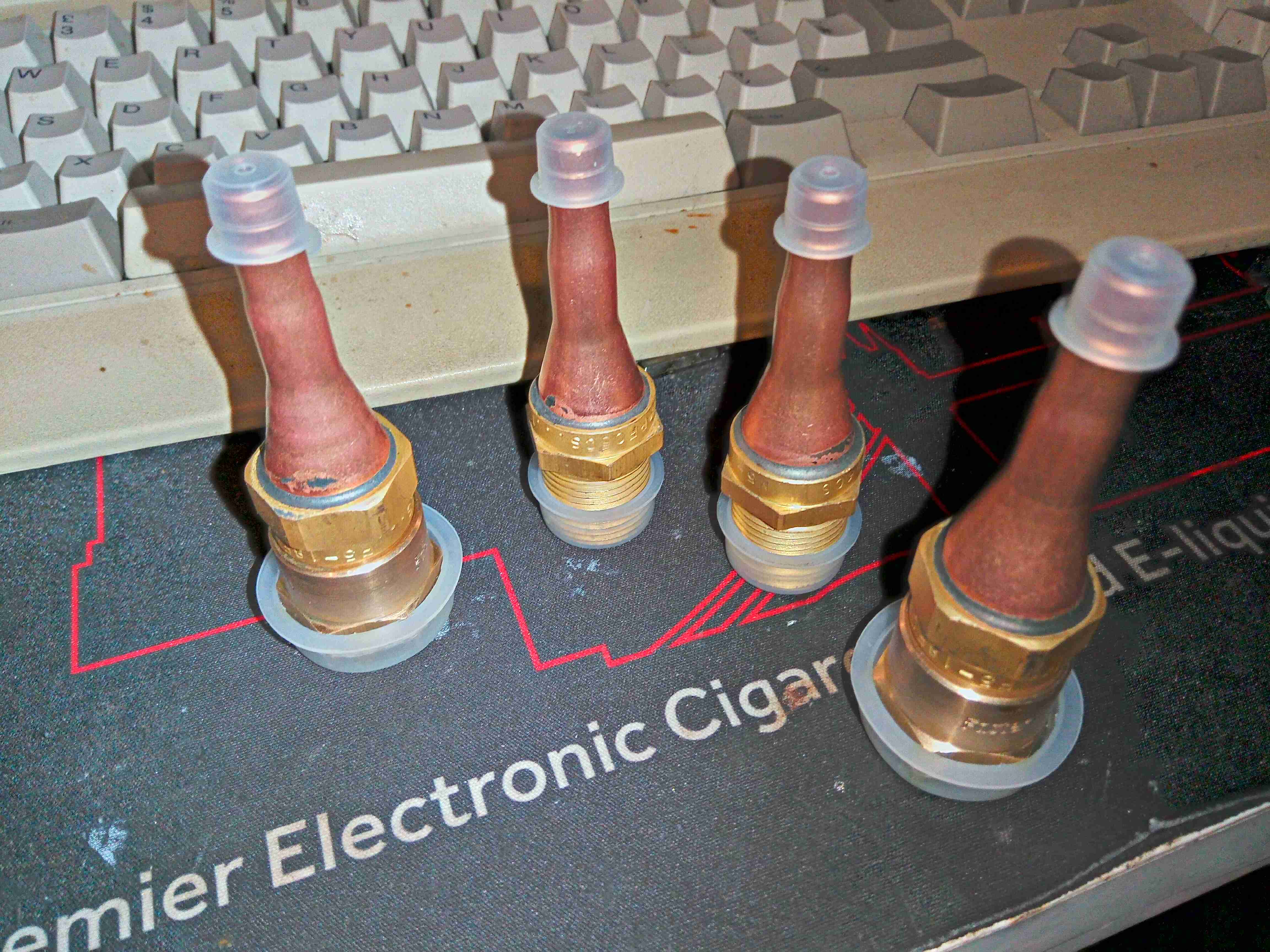
I decided to keep most of the weight, control & wiring internal to the main power trolley which goes everywhere with us while camping, this obviously required the refrigerant lineset to be dis-connectable from the fridge cabinet for transport, and has the requirement for a flexible lineset between the two. The marine-grade refrigeration systems destined for custom builds are supplied with dis-connectable copper linesets with special fittings, so I went in search for a supplier of said fittings. The need for flexibility & re-usability means I can’t use the copper lines in this application – work hardening will quickly cause the copper pipe to crack.
Parker-Hannifin supply these special fittings, and seem to be the original manufacturer – considering they specialise in fluid power & control, this isn’t a surprise. However ordering from them is a nightmare, so no go there. I did find an Italian supplier of equivalent fittings, the Faster Coupling RF series:
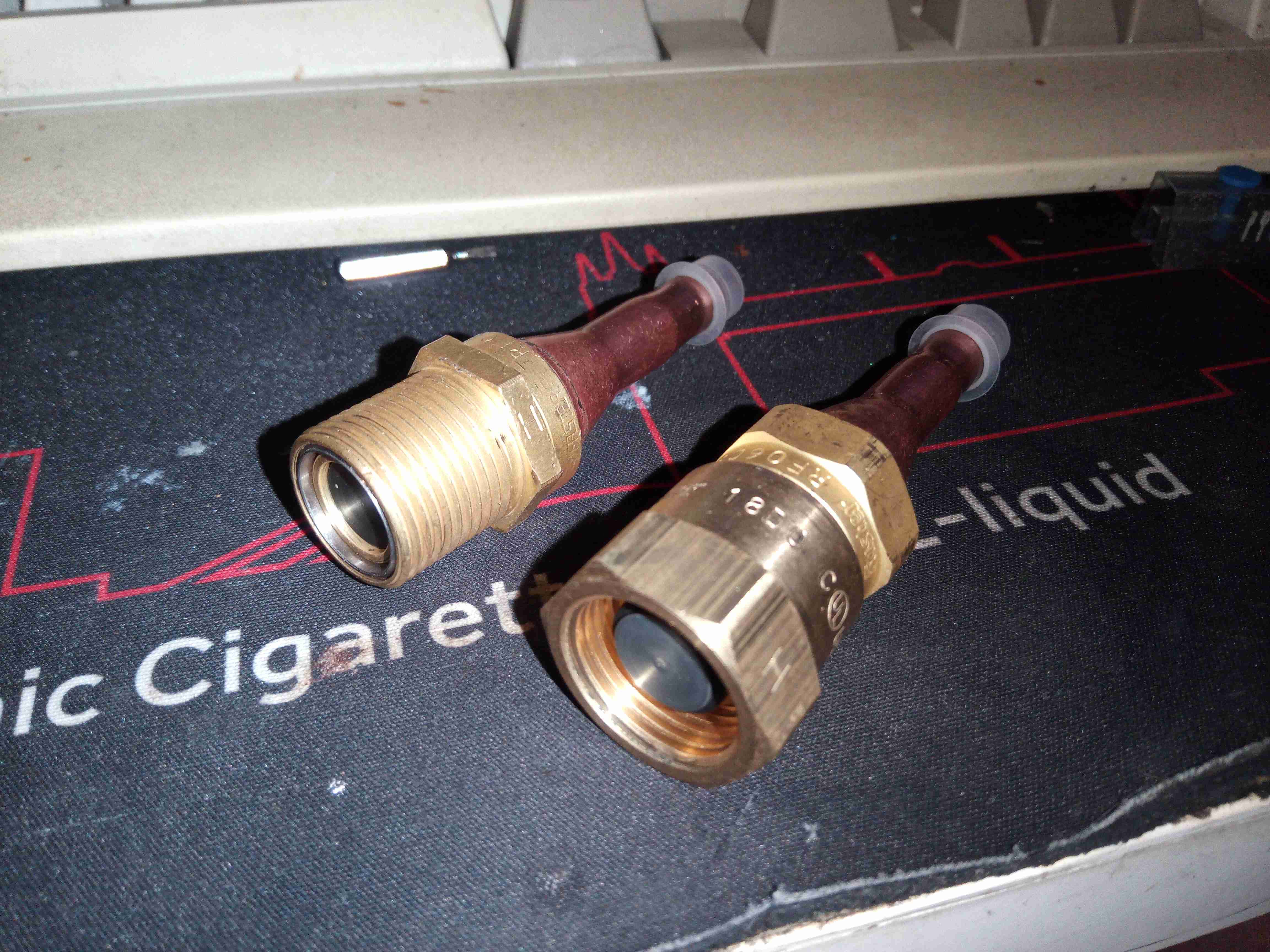
Lineset Disconnect Fittings
Luckily, I was able to get a distributor in the UK to order these in for me, but they are a bit expensive, at ~£130 for two pairs. I sized these for 1/4″ to match the compressor lines. They’re quite well made from brass, with copper tails silver-soldered for braze connections.
Fitting Pair
The fittings screw together like hydraulic couplings, however these are designed for very low leakage, and very low admission of air when connecting them together.
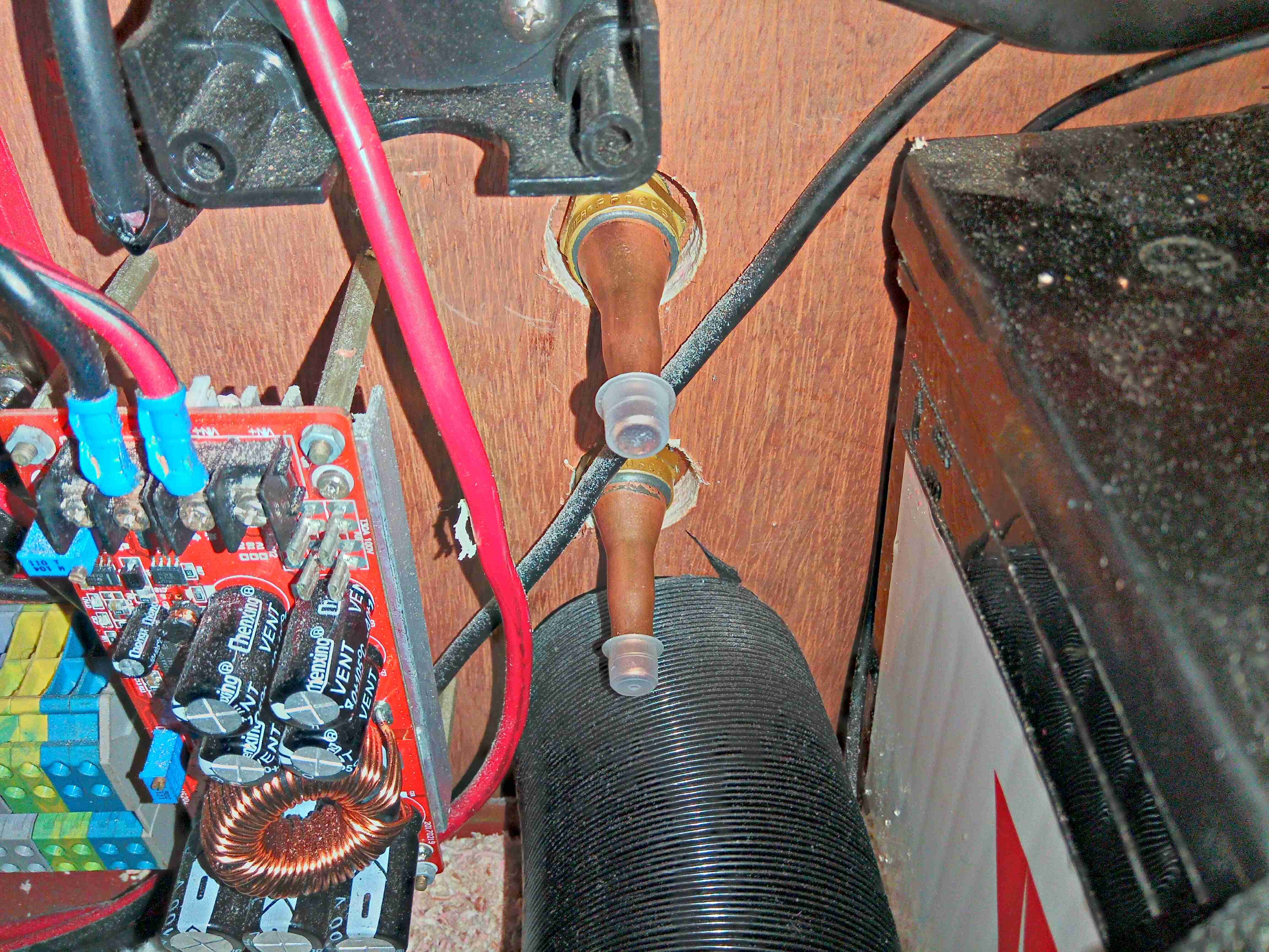
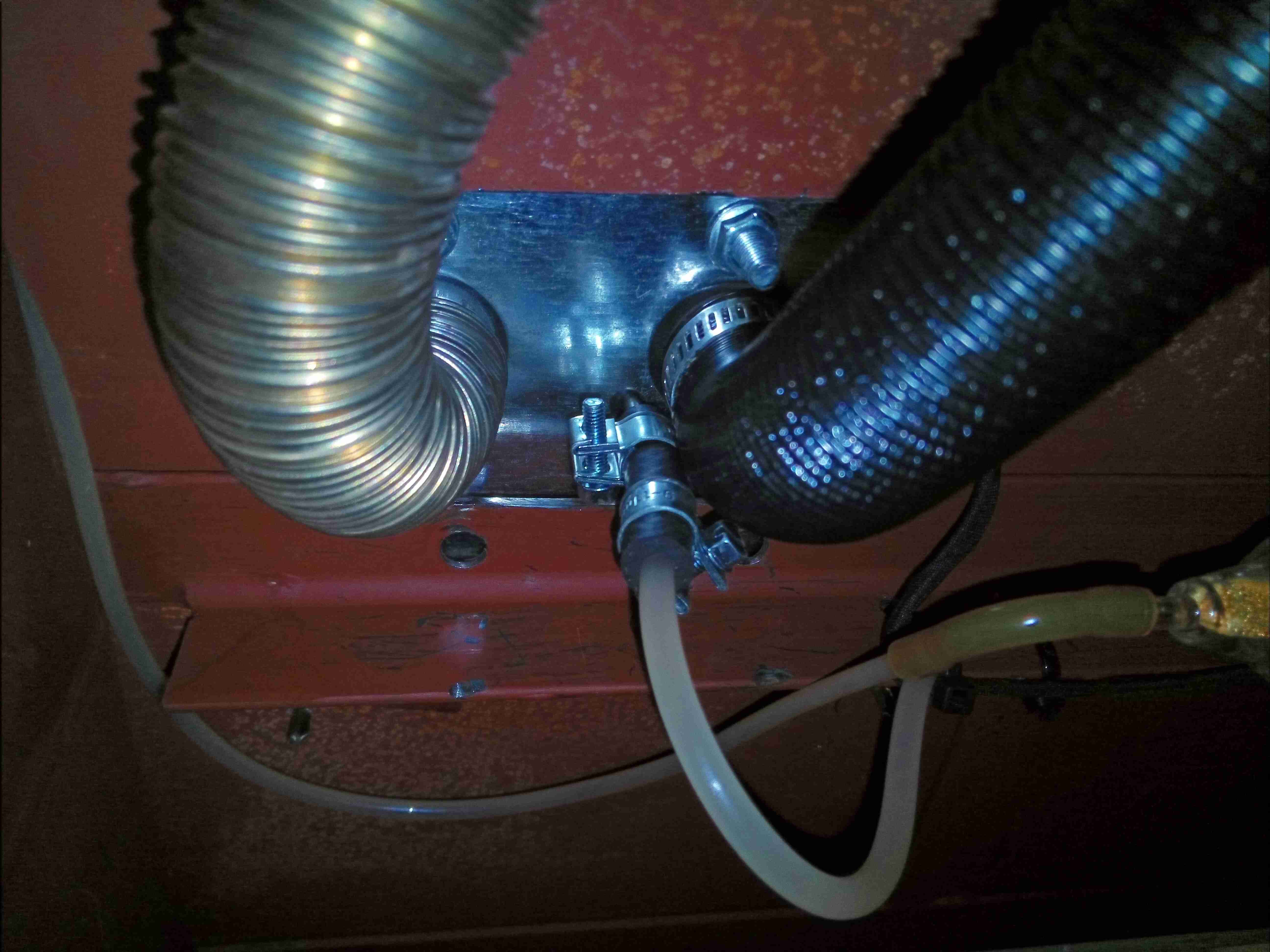
Fitted To Frame
Time to get these panel mounted on the back of the power trolley. The 1/2″ plywood frame is too thick to mount these directly, so I had to improvise a mounting plate:
Fitting Mounting Plate
A bit of FR4 PCB material with suitable holes bored makes for a nice thin panel with high strength. I will colour-code these to make sure the suction & discharge lines aren’t mixed up when connecting, considering they’re both the same size.
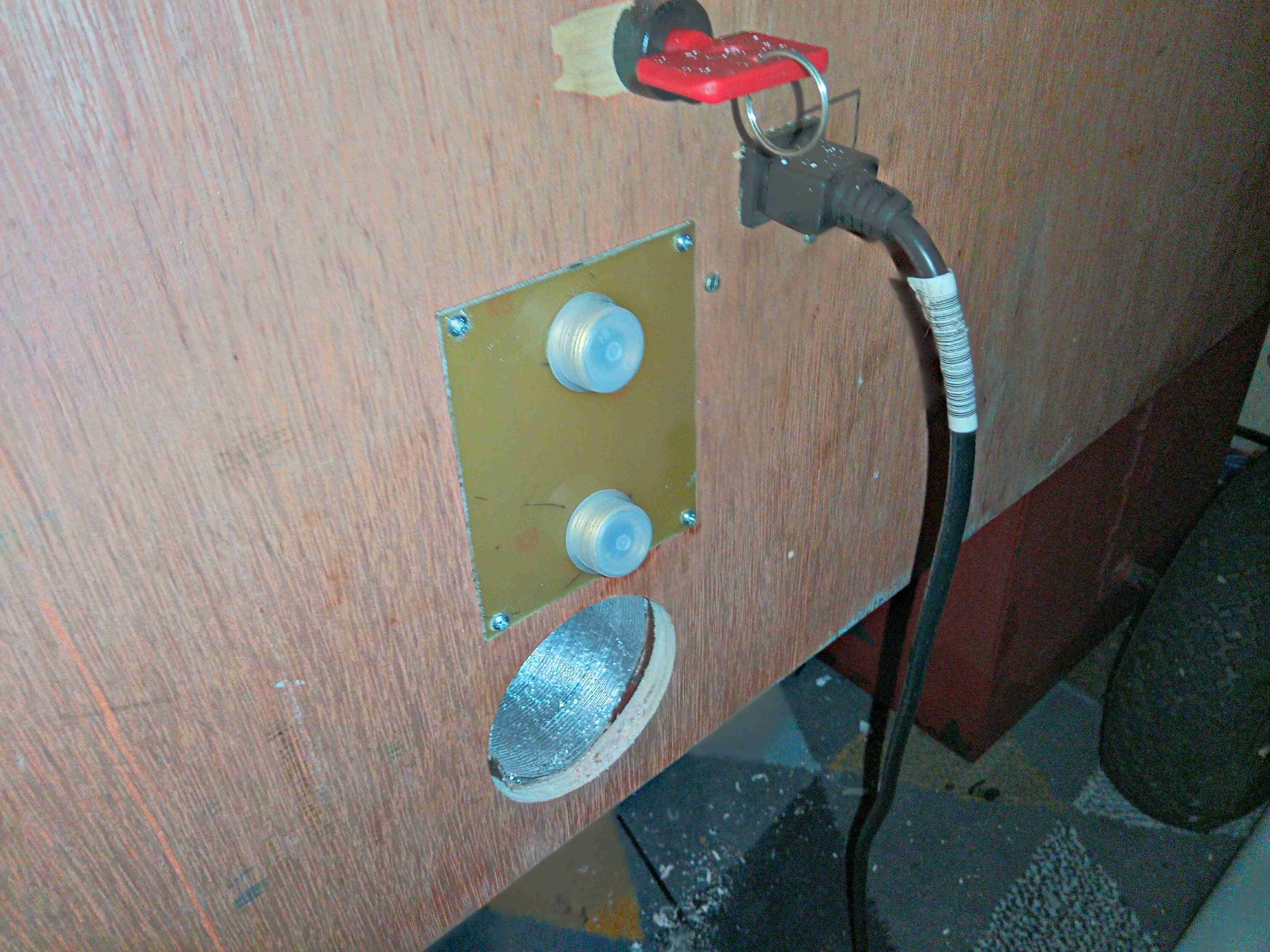
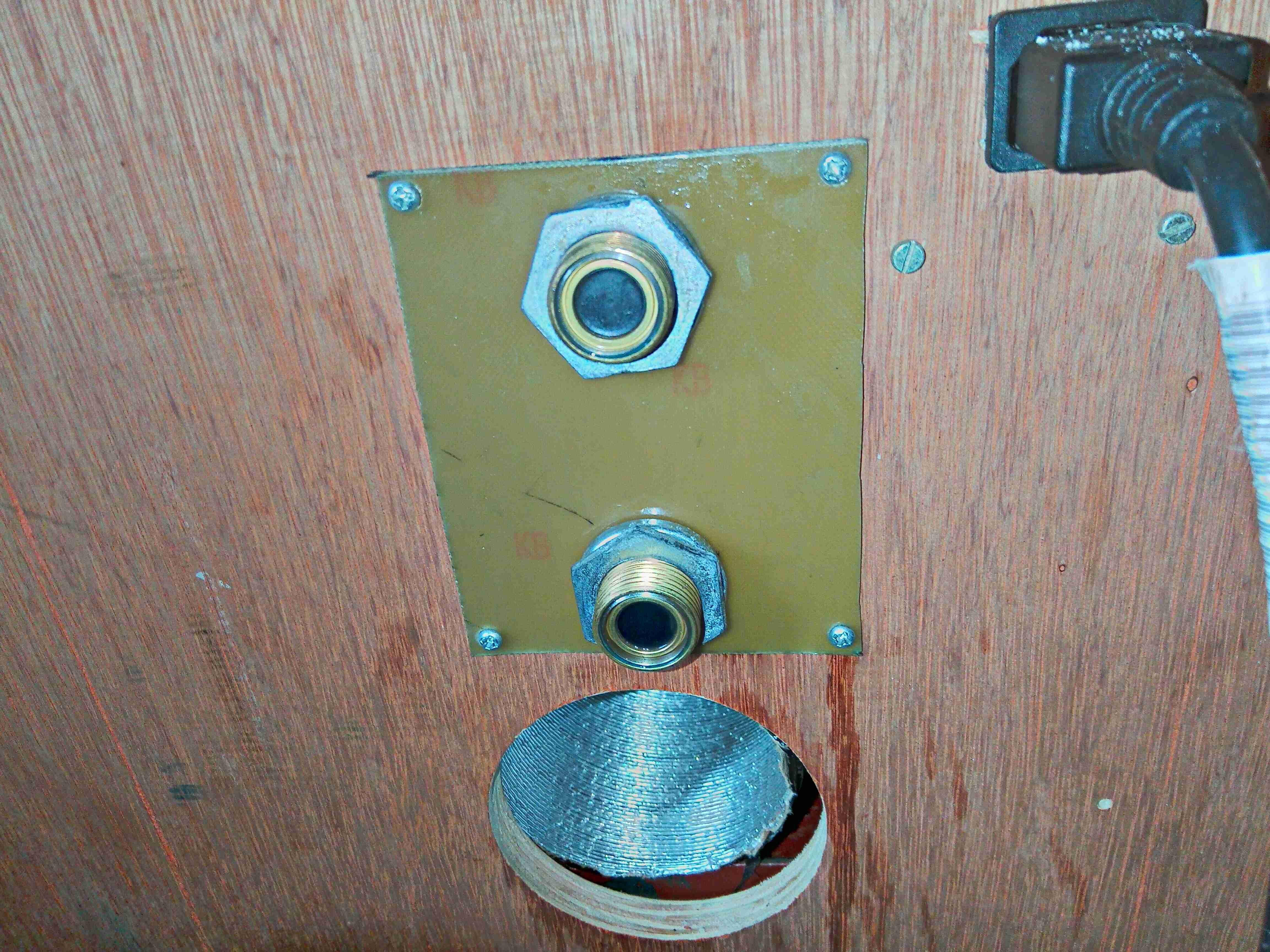
Refrigerant Fittings
The fittings are secured with M20 conduit nuts & spring washers.
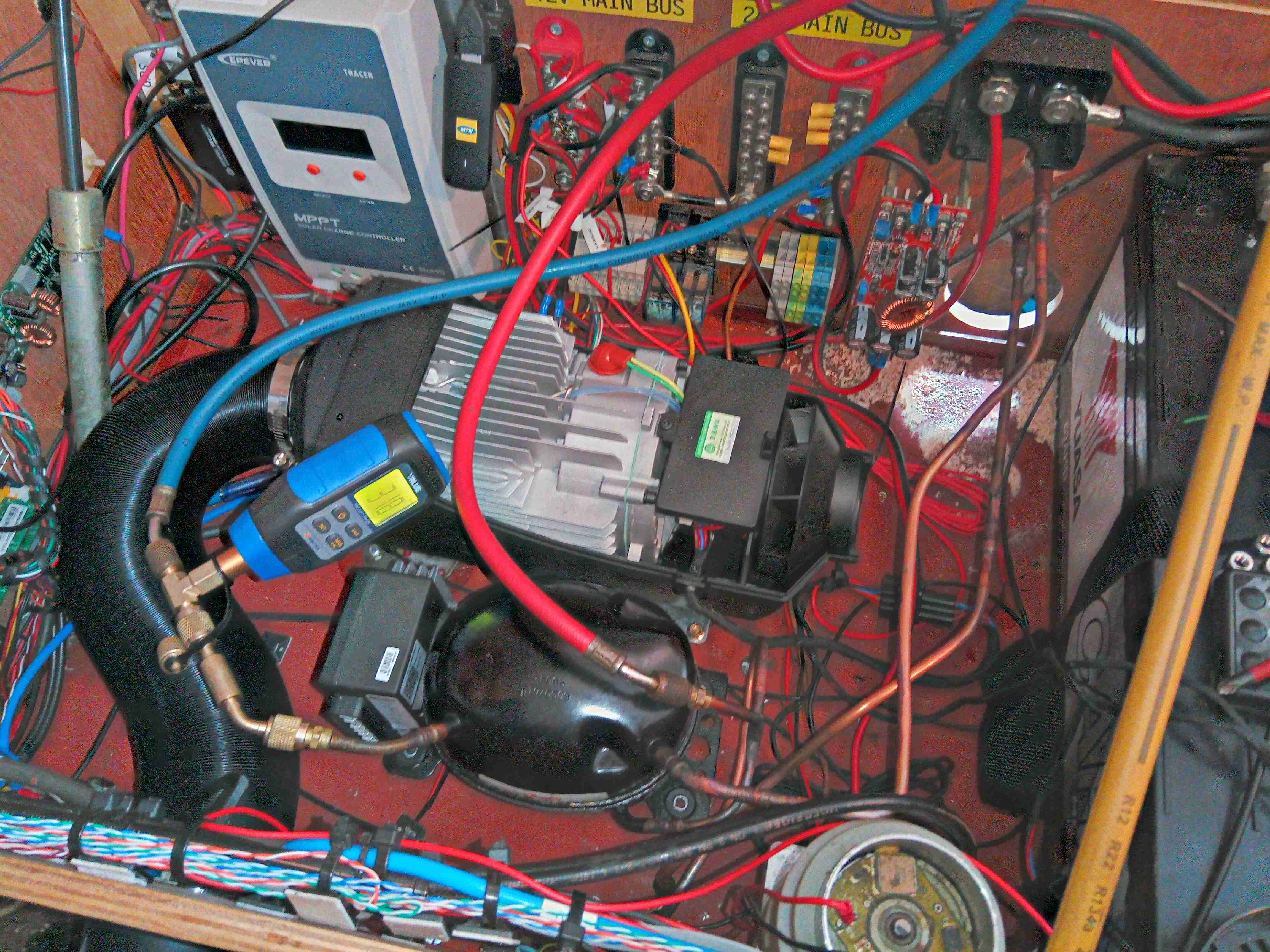
Compressor Unit
Here I’ve got the compressor fitted & all the lines brazed, and have the system under vacuum to get any traces of water out. Side note: the RF series couplings are *very* difficult to braze with just a single burner MAPP torch – keeping the end of the fitting with the rubber seals submerged in water to stop them melting just conducts too much heat away from the copper tail too quickly. I did successfully manage to get them brazed though, and this section of the system holds both vacuum & pressure to 12 bar. The condenser coil is mounted underneath next to the fuel tank:
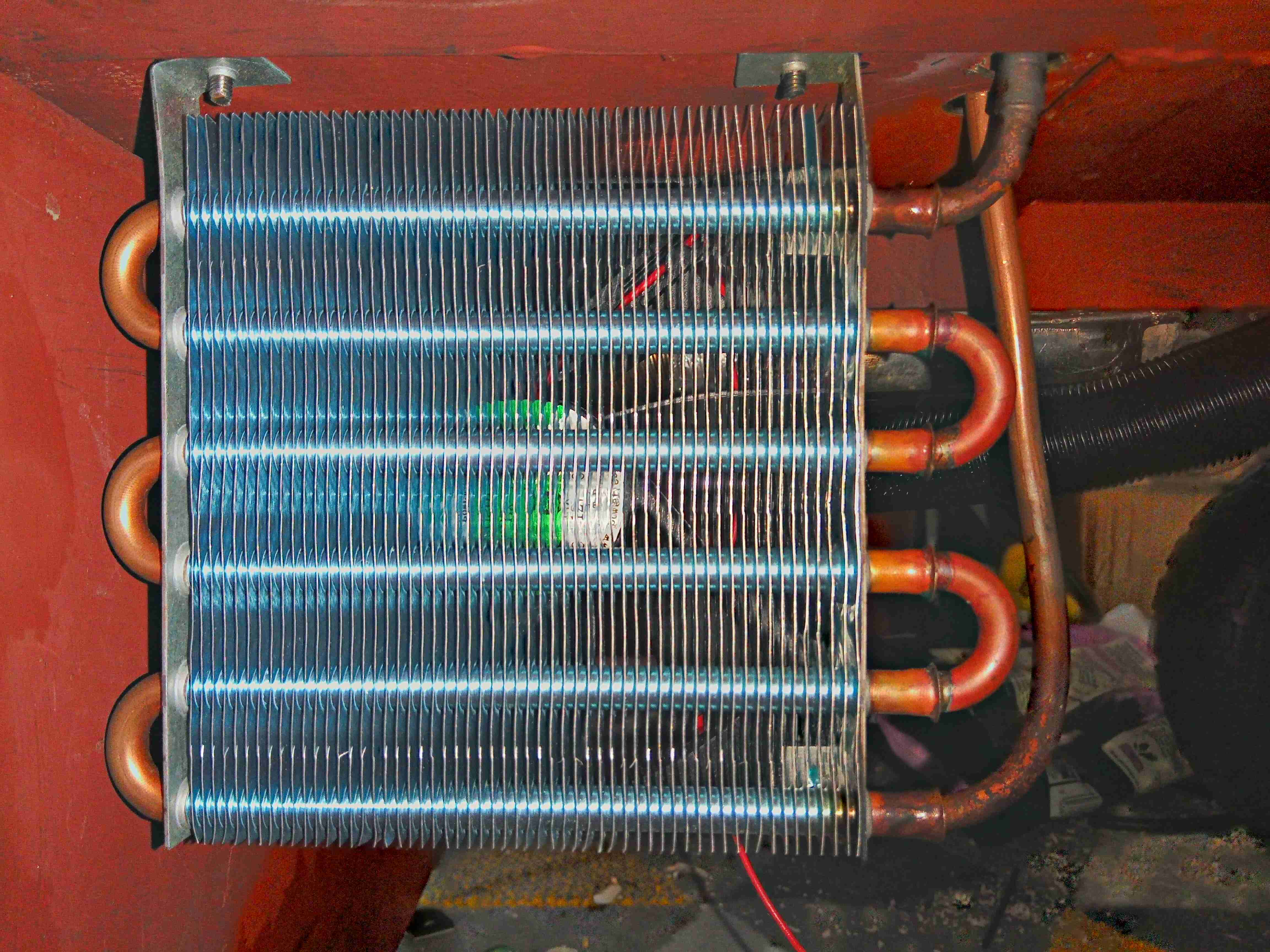
Condensing Coil
There’s a 120mm fan behind for forced air cooling, with the refrigerant lines run up to the compressor above.
I’ll be back soon with the build of the fridge cabinet & evaporator section!
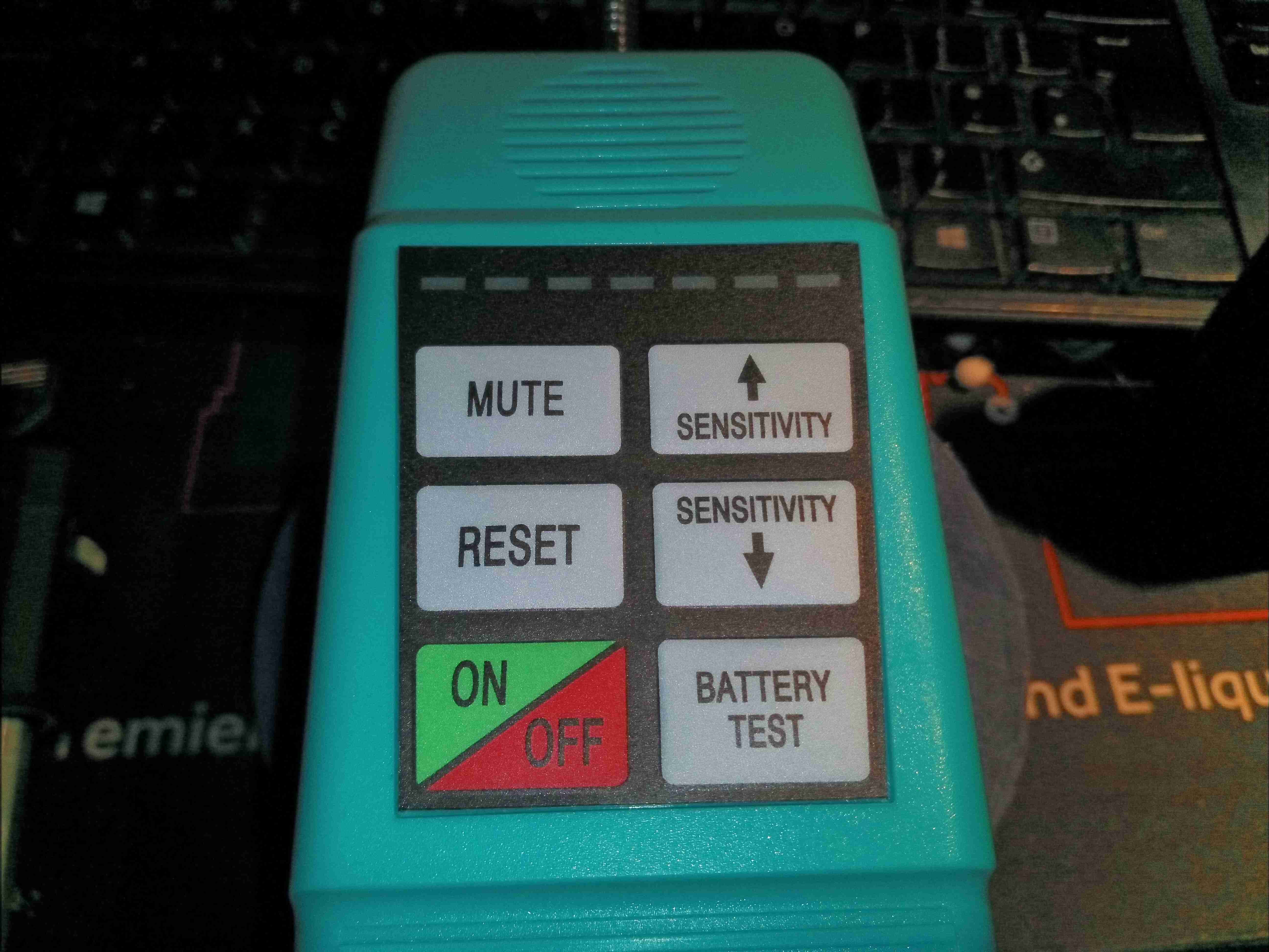
Here’s a useful device, for detecting leaks in refrigerant systems. These units use a high-voltage ionisation detection method using a probe at the tip with a sharp needle, similar to an ioniser to detect changes in conductivity of the surrounding gas.
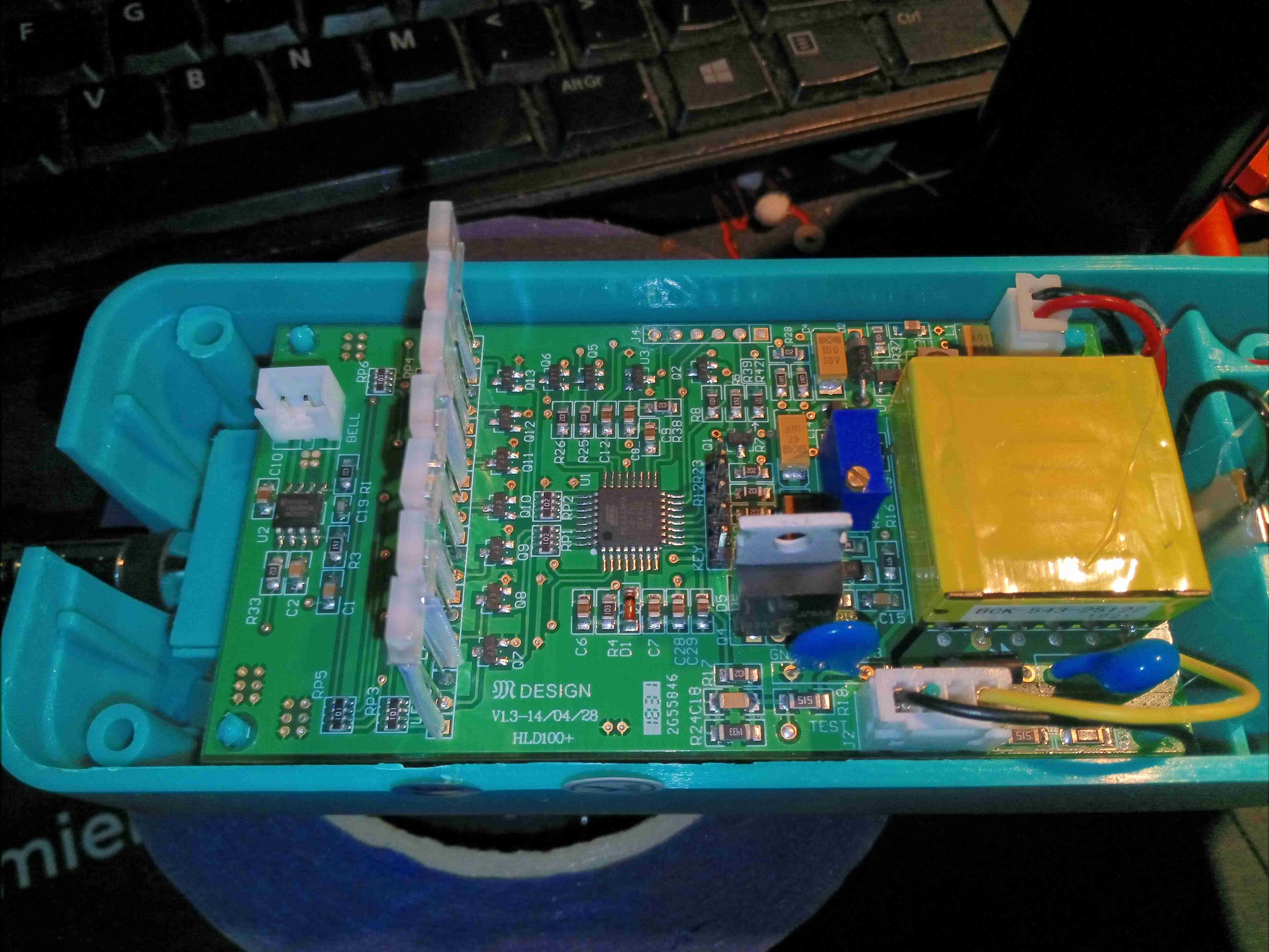
PCB Top
Removing the front case of the unit reveals the PCB, with it’s row of indicator LEDs on the top. The high voltage transformer is on the right, with it’s switching transistor. The probe swan neck is on the left.
PCB Right
The PCB is fairly heavily populated, and all a single-sided load, no doubt to reduce manufacturing costs. The main power input from the battery is on the bottom left, with a small switching regulator to the right supplying power to the control logic & microcontroller. There’s a multi-turn potentiometer, probably for adjusting the output voltage of the HT section. The header in the centre of the board is the connection point of the membrane keypad on the front of the unit.
PCB Left
Not much more to see on the left side of the board, there’s the connection for the buzzer far left, and the main switching MOSFET for the high voltage transformer in the centre. The high voltage output is on a JST connector bottom right! I suspect the HV converter is fully under the control of the microcontroller in this unit, as there doesn’t appear to be any other control function present.
Microcontroller
The main microcontroller is an ATMEGA48, with it’s programming header on the far right of the board.
High Voltage Output
Finally, there’s the high voltage output section of the board with a couple of anti-tracking slots to prevent flashover. There’s a rectification diode, in half wave, a small smoothing capacitor before the string of current limiting resistors on the output of the unit to the probe. I haven’t been able to work out where the microcontroller is actually getting the gas conductivity measurement from – it may be measuring the input current drawn by the HV converter or it may be measuring the output current via one of the current-limiting resistors on the HV output.
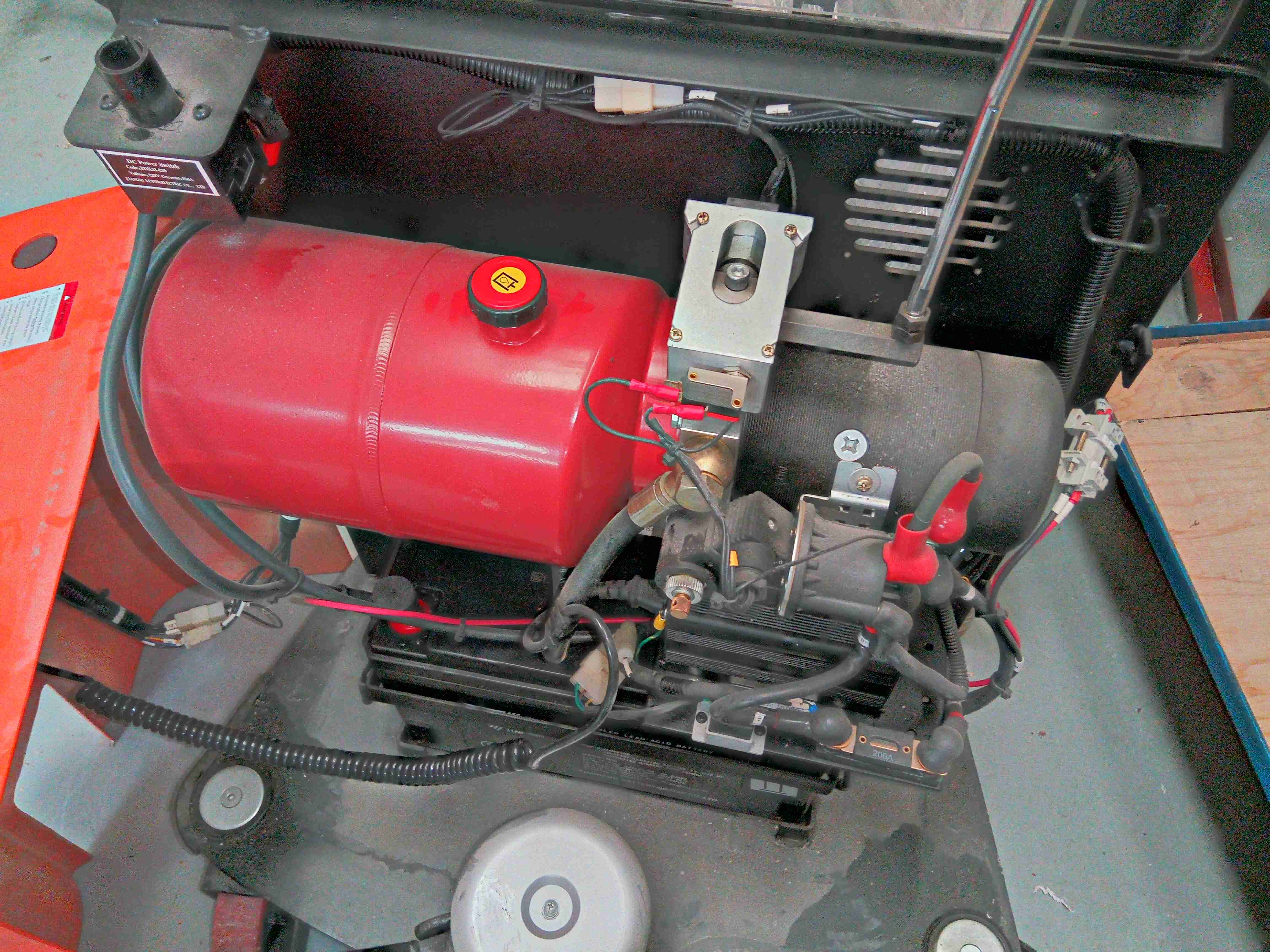
At work we have a human-propelled hydraulic stacker, which recently started to drop under load, with no valve operation. I immediately suspected the lowering valve on the hydraulic pump unit, so set to work getting a replacement fitted.
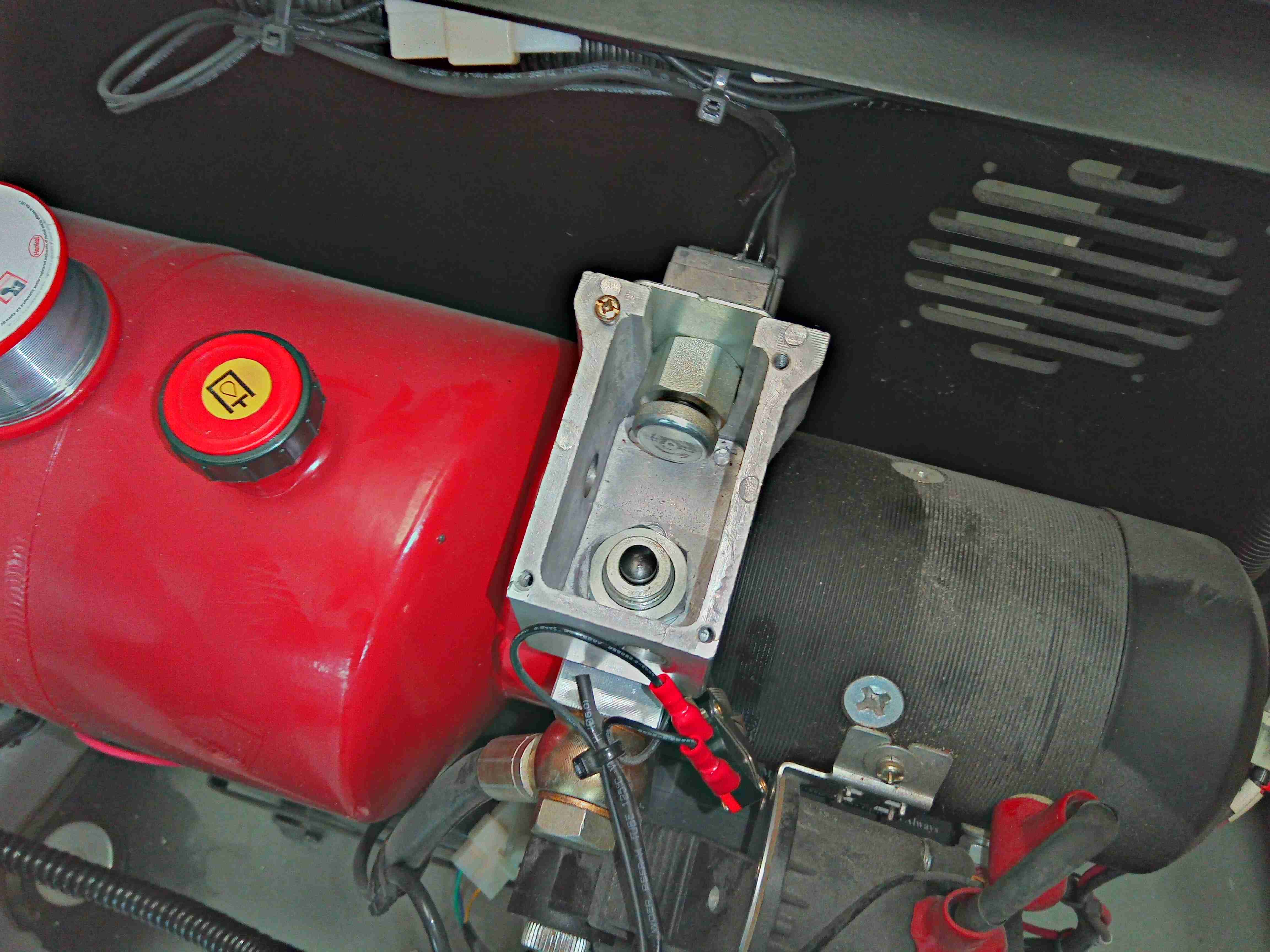
Unit Overview
After removing the GRP cover of the mechanics bay, the main hydraulic unit is visible mounted on the top of the frame. Powered by a large 12v SLA battery below, the hydraulic power pack consists of a large 12v motor, gear pump, valve block & hydraulic oil tank. The valve we’re after is hidden at the moment inside the control lever mounting.
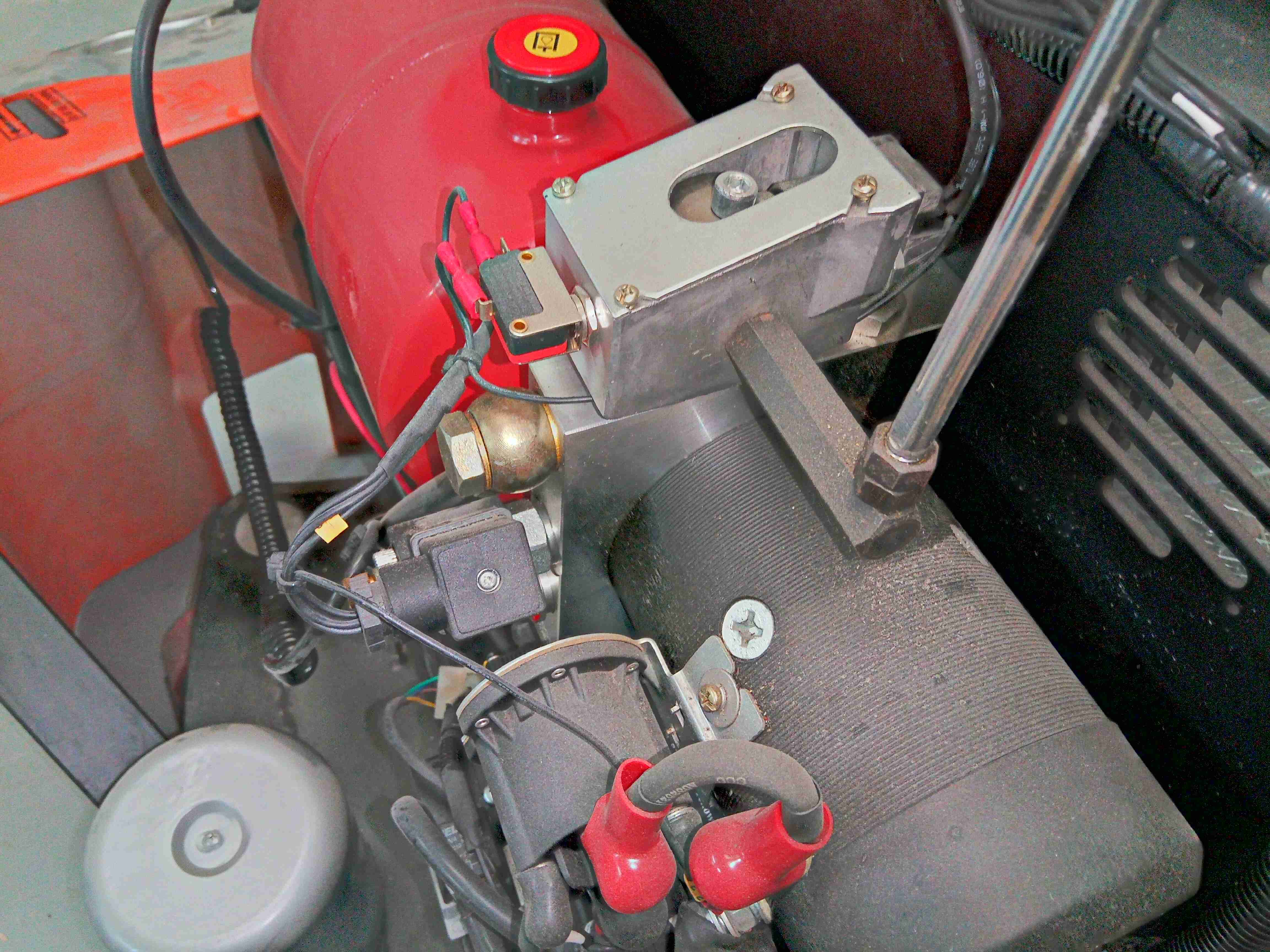
Hydraulic Valve Block
Here’s a better view of the control lever mountings. There’s a pair of microswitches for activating the lowering speed-control valve, and the main contactor which switches the high current to the main motor.
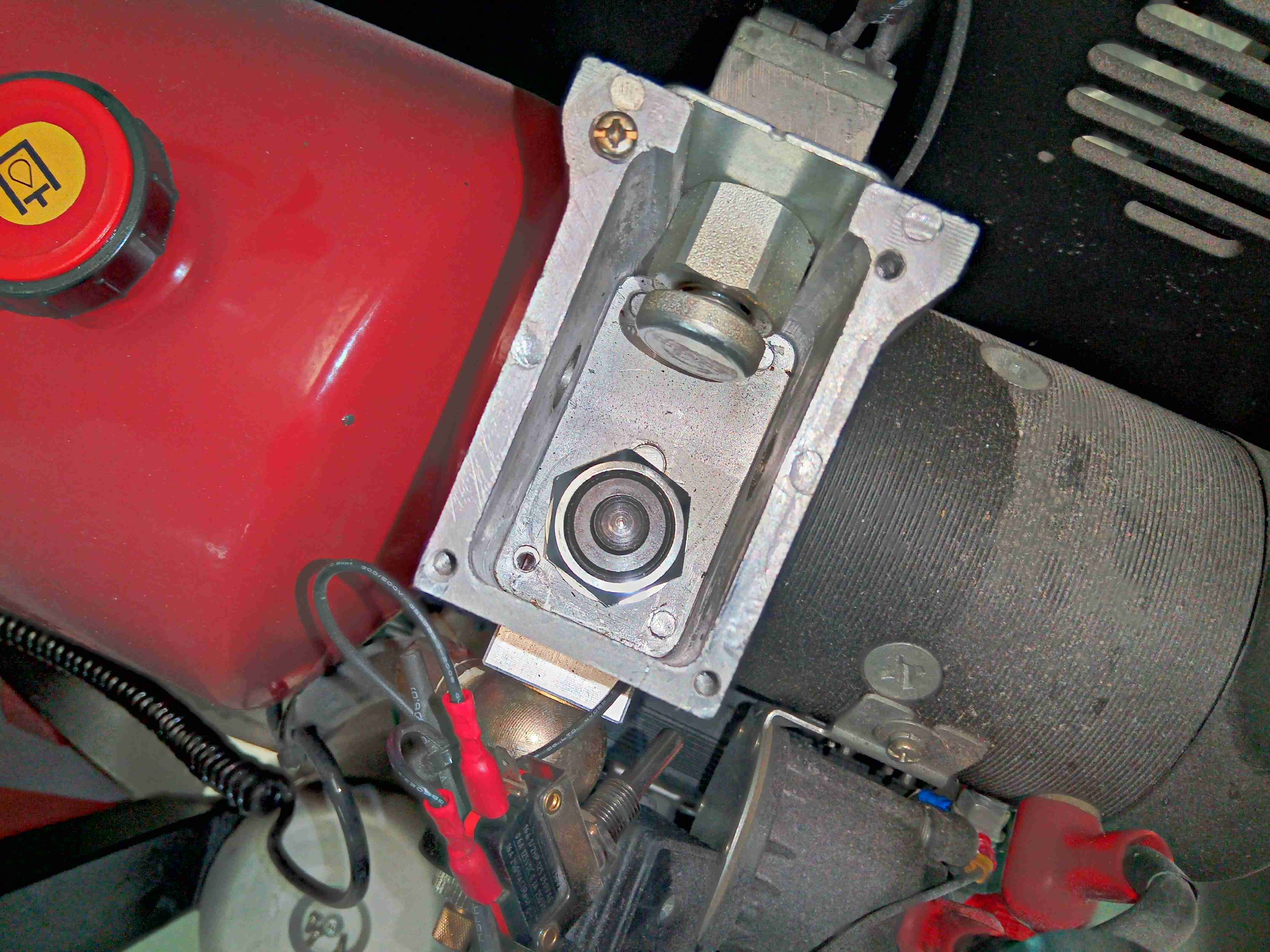
Lowering Valve Mounting
Removing the actuator cam & control lever reveals the valve hiding at the bottom of the mounting cage. I’ve removed the microswitch which operates the lowering speed control valve to gain better access, but the main switch that operates the contactor can stay in place at the top.
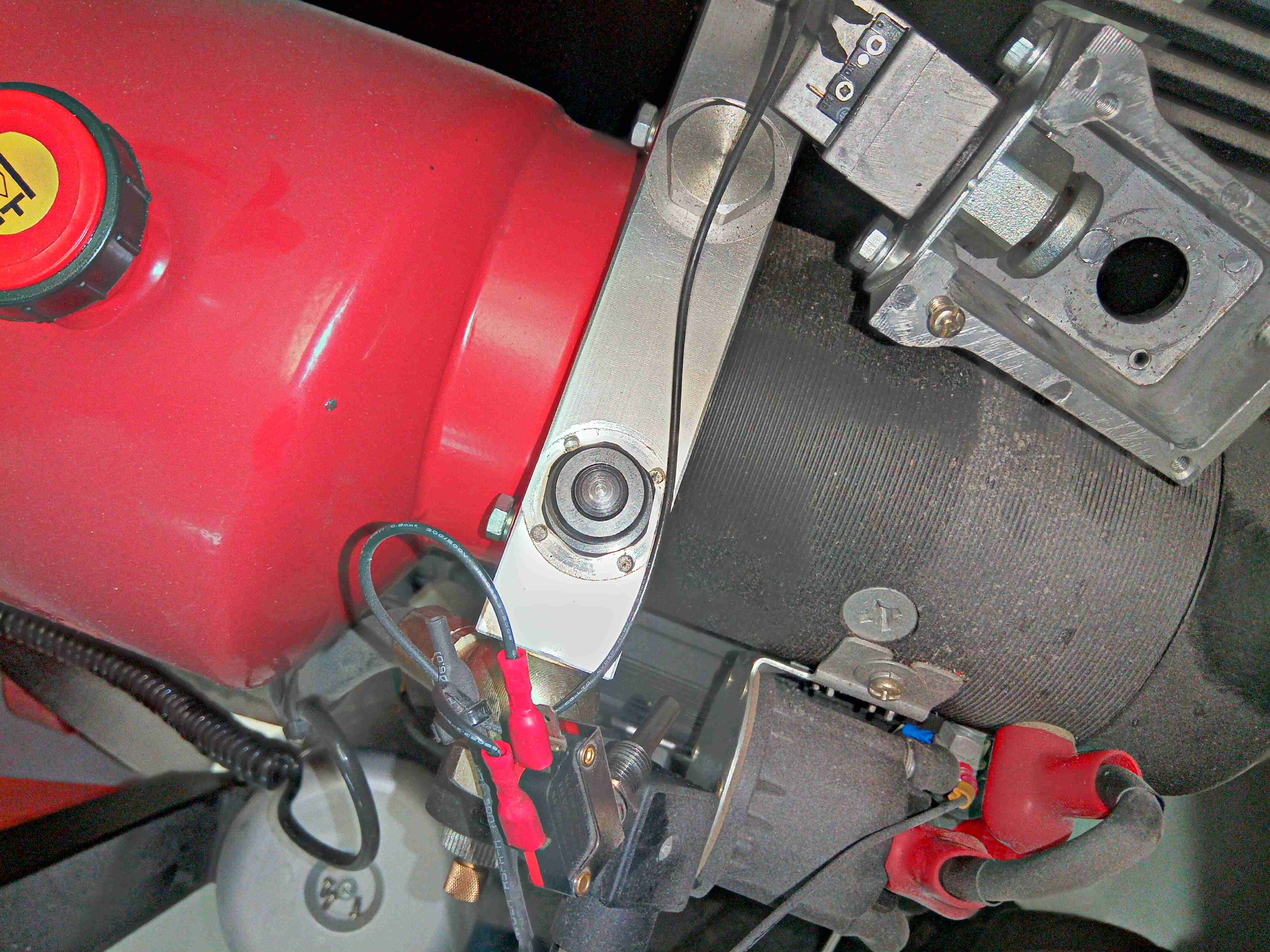
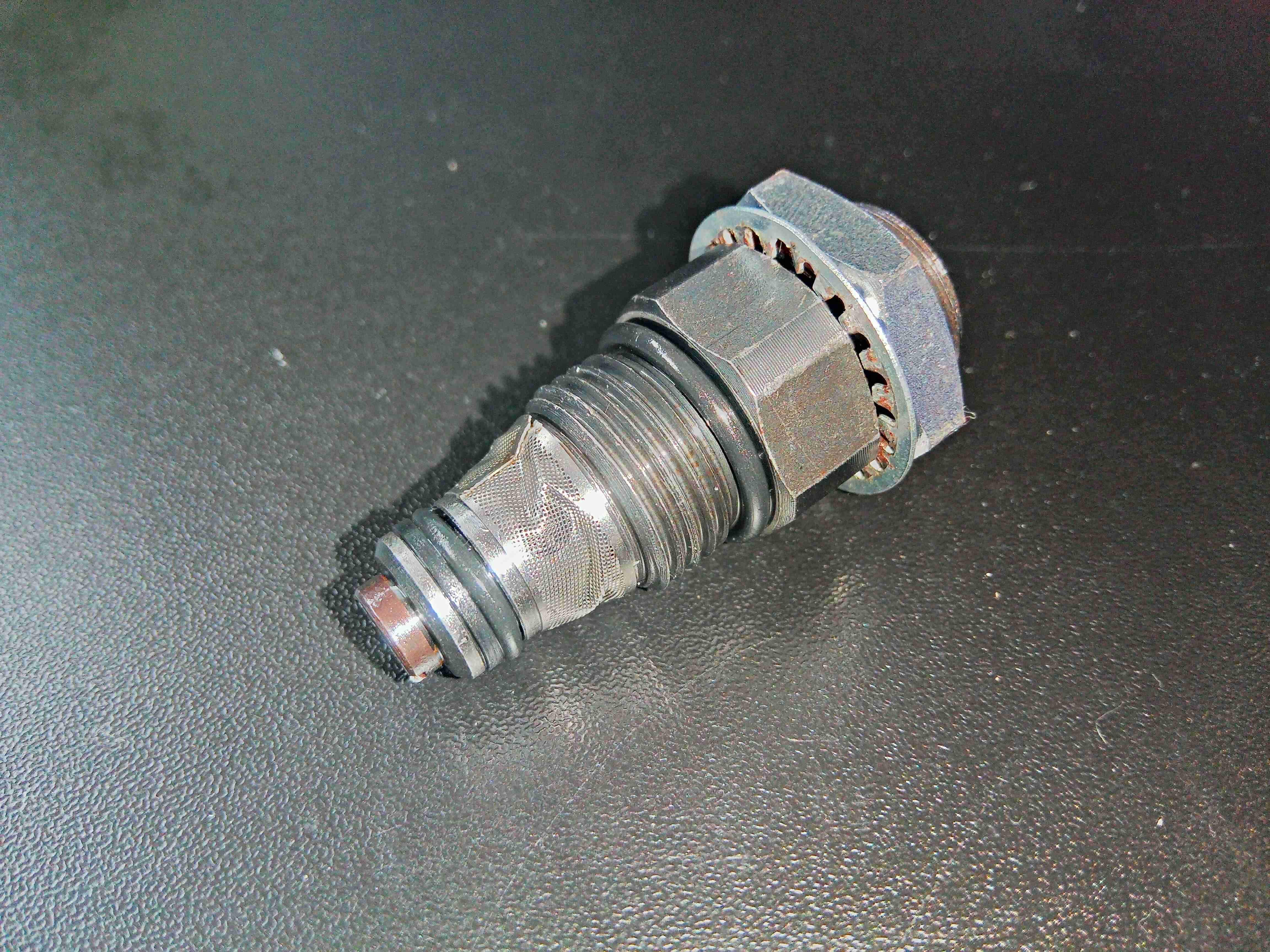
Bare Valve
Getting in with a 1″ socket allows the retaining nut holding the mounting cage to be removed, showing the actual valve in the hydraulic block.
Old Valve
The valve is removed by simply unscrewing it from the main unit. Here’s where cleanliness comes in – the hydraulic system is now open to the environment, and the close tolerances in the valves & main pump will not tolerate dirt & grit getting in! This is a simple poppet valve, the main seal actually being a metal-to-metal tapered surface, and the problem this one has had is the O-Ring seals have failed. The rubber has gone very hard over the 4 years this unit has been in service, and have started to disintegrate. This is still a perfectly serviceable valve once the seals are changed, even if the filter screen has been a little damaged.
Replacement Valve Fitted
I’ve fitted the new valve to the hydraulic block here, and a test done to ensure the load is held on the hydraulic cylinder. Reassembly is simply the reverse of teardown.
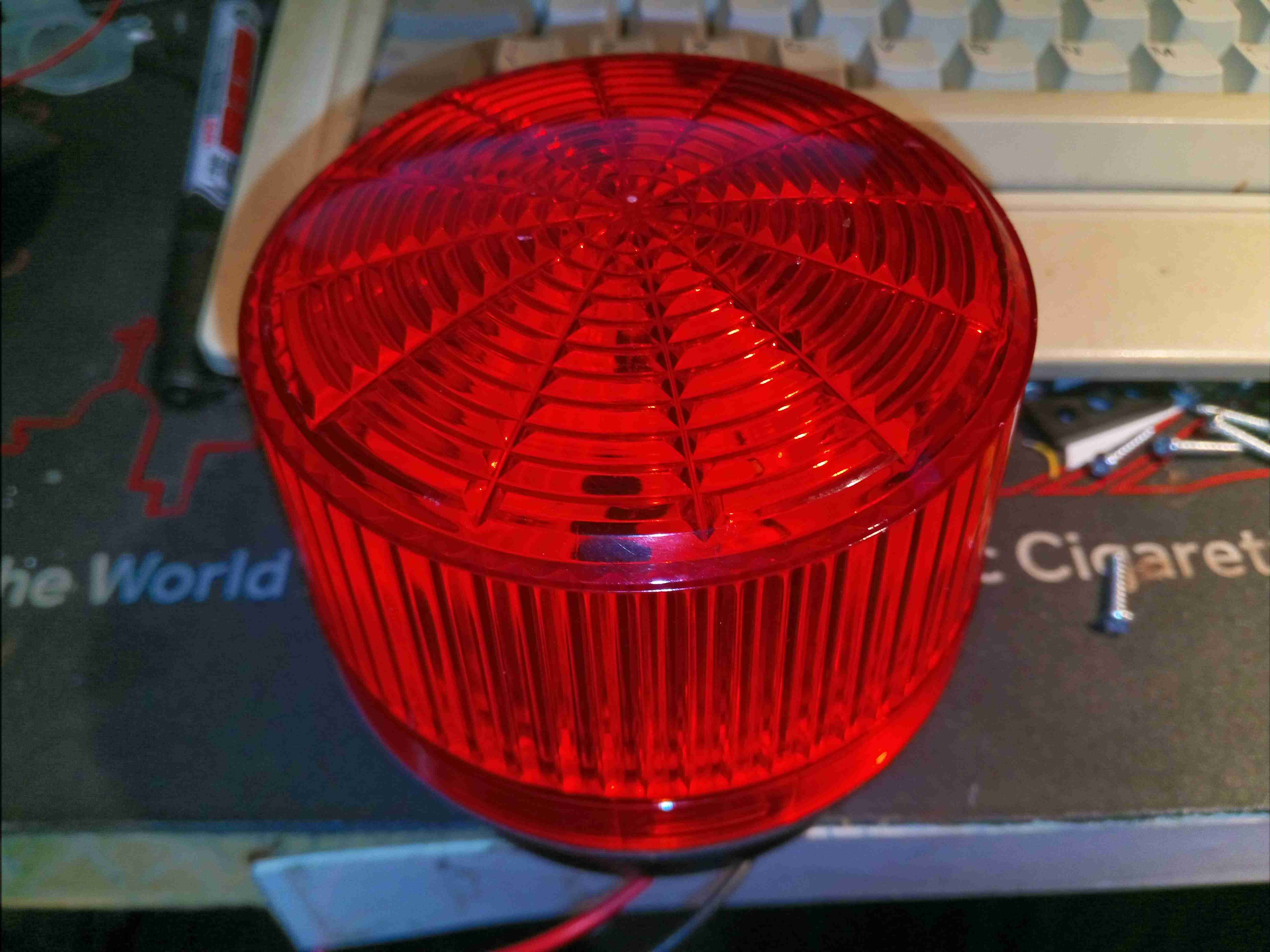
Here’s something anyone in the industrial sector will recognise – it’s a strobe beacon, which continually flashes with power applied to alert operators of a hazard. These older ones are Xenon tube based, instead of LED, so contain a bit more circuitry & some high voltages.
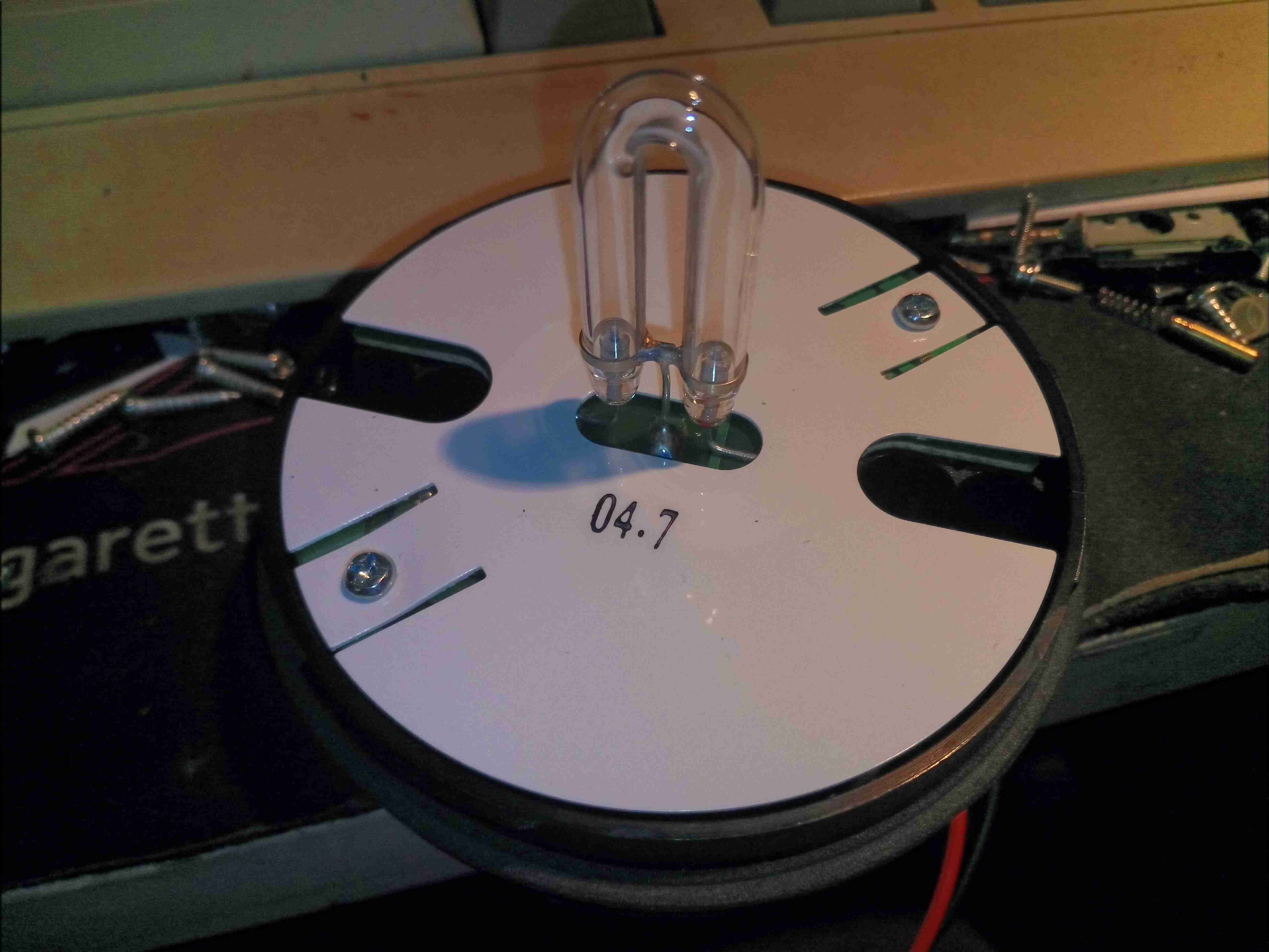
Xenon Flash Tube
Unhooking the lens reveals the Xenon lamp itself, a horseshoe format tube. A high DC potential is applied across the electrodes of the tube, below the ionisation voltage of the Xenon gas inside. When a flash is called for, a very high voltage – several kV – is applied to a 3rd trigger electrode, applied to the outside of the glass. The high electric field generated is sufficient to ionise enough gas to initiate the main discharge between the electrodes. Since the lamp is across a large capacitor, a massive current flows, generating a high-intensity flash.
Insulator Removed
Removing the pair of screws which secure the insulator & PCB reveals the board itself, which is of cheap single-sided construction. There’s no isolation on this circuit, between the internal HV side & DC input.
Main PCB Top
Flipping the board shows all the components. The largest part here is the main flash capacitor in the middle, a plastic film type, 4.7µF 400v. This will be charged to around 350v before the tube is triggered. Charging of the capacitor is done by the transformer at bottom right, switched by the transistor next to it. There are no ICs in this unit to control any timing of the DC-DC converter, so this is probably based around a blocking oscillator. A smaller capacitor to the top right of the main flash cap is part of the trigger circuit, which is charged through a resistor from the main HV supply. When the voltage on this capacitor reaches a high enough level, the large SCR on the left side of the board switches on, dumping the charge on that capacitor through the trigger transformer, the small yellow device with the white wire. This small transformer generates the high voltage pulse to trigger the flash lamp.
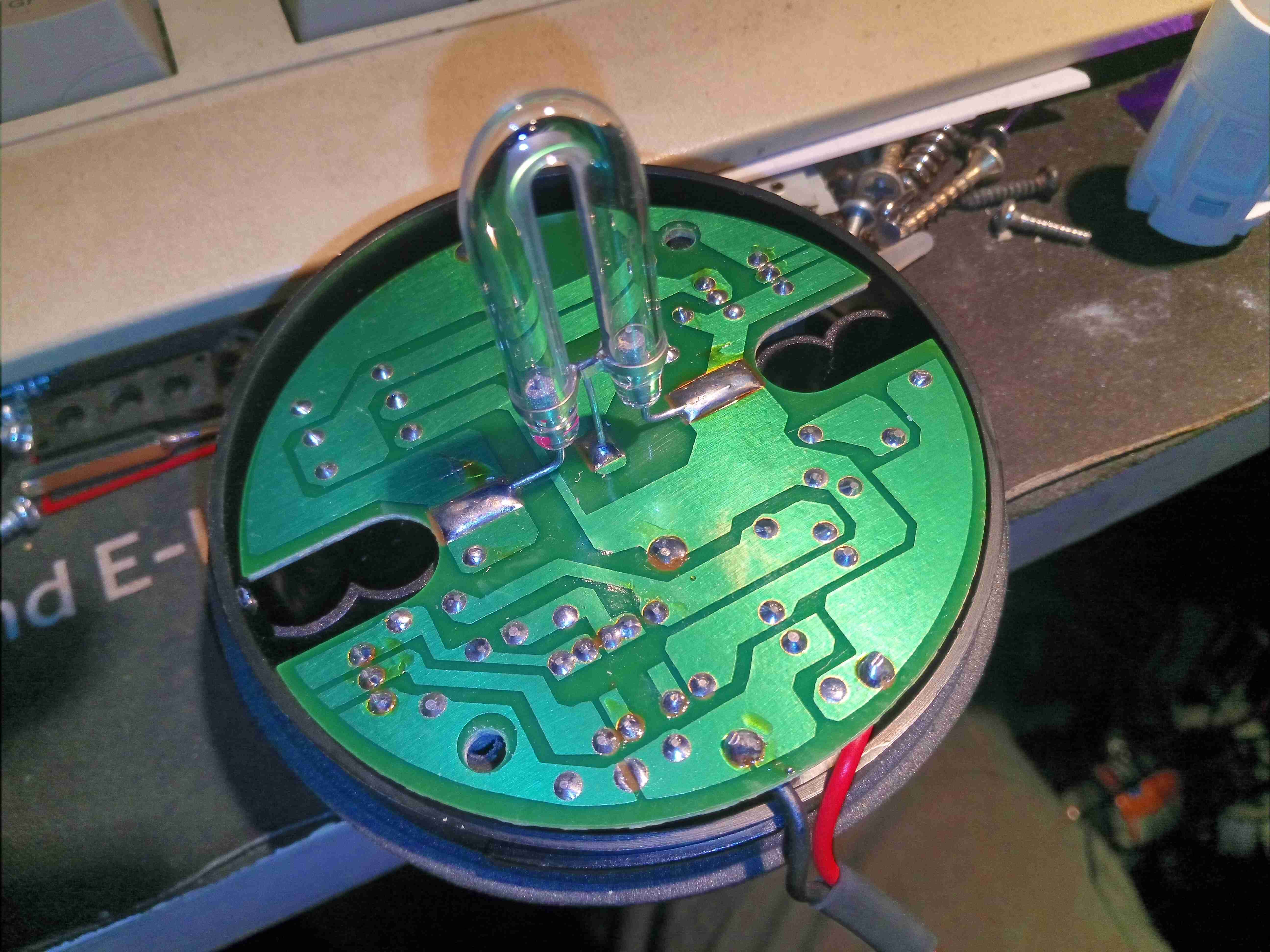
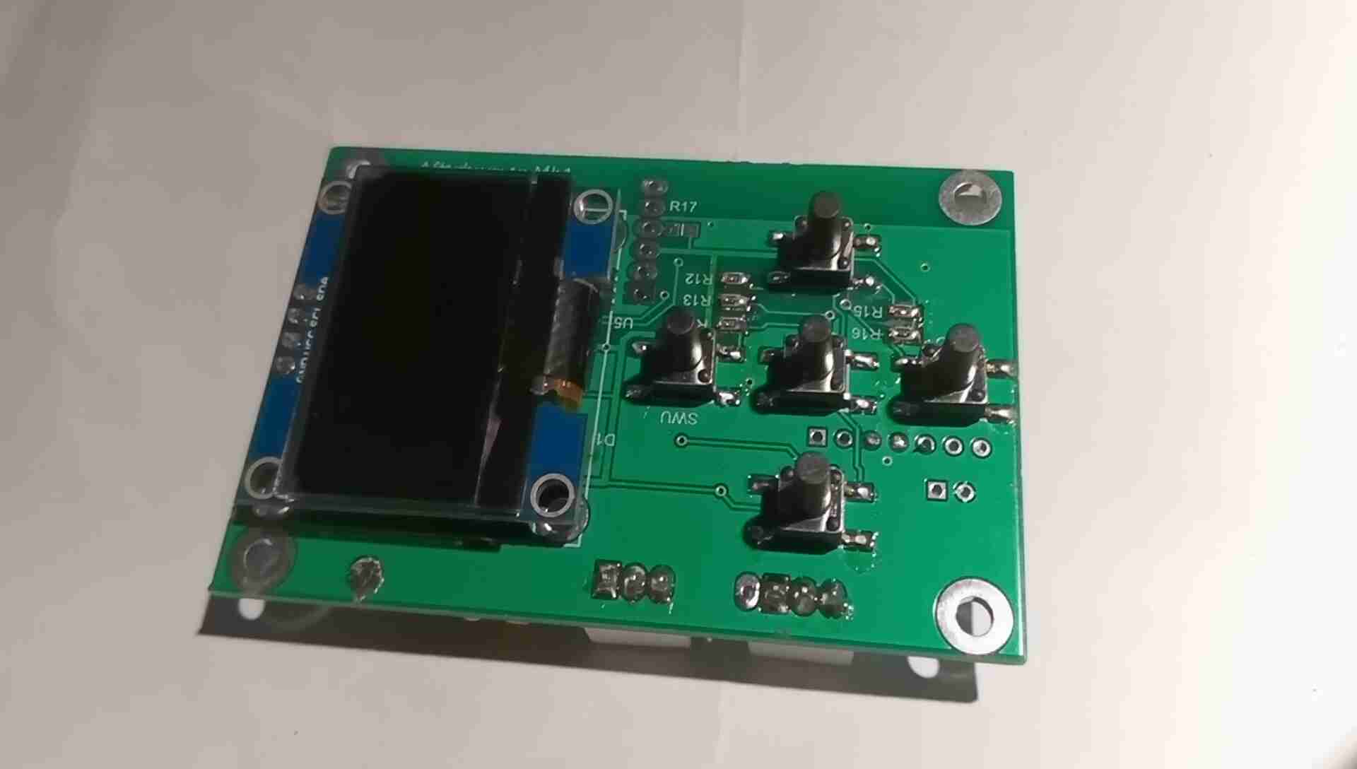
While I’m pretty happy with the Chinese diesel heater replacement for the old Eberspacher on the trolley, the stock controller leaves much to be desired. While functional, it’s fairly unresponsive, bulky & doesn’t allow external control as the Eberspacher did with it’s simple ON/OFF signal. So after a massive amount of searching on the web, (it wasn’t easy to find, damn SEO!), I discovered a project by a chap in Australia who has reverse engineered the communications protocol of these heaters, & built a fully custom controller. This is based around the ESP32 Wi-Fi microcontroller, and a Bluetooth HC-05 module. Display is by means of a 1.3″ OLED screen.
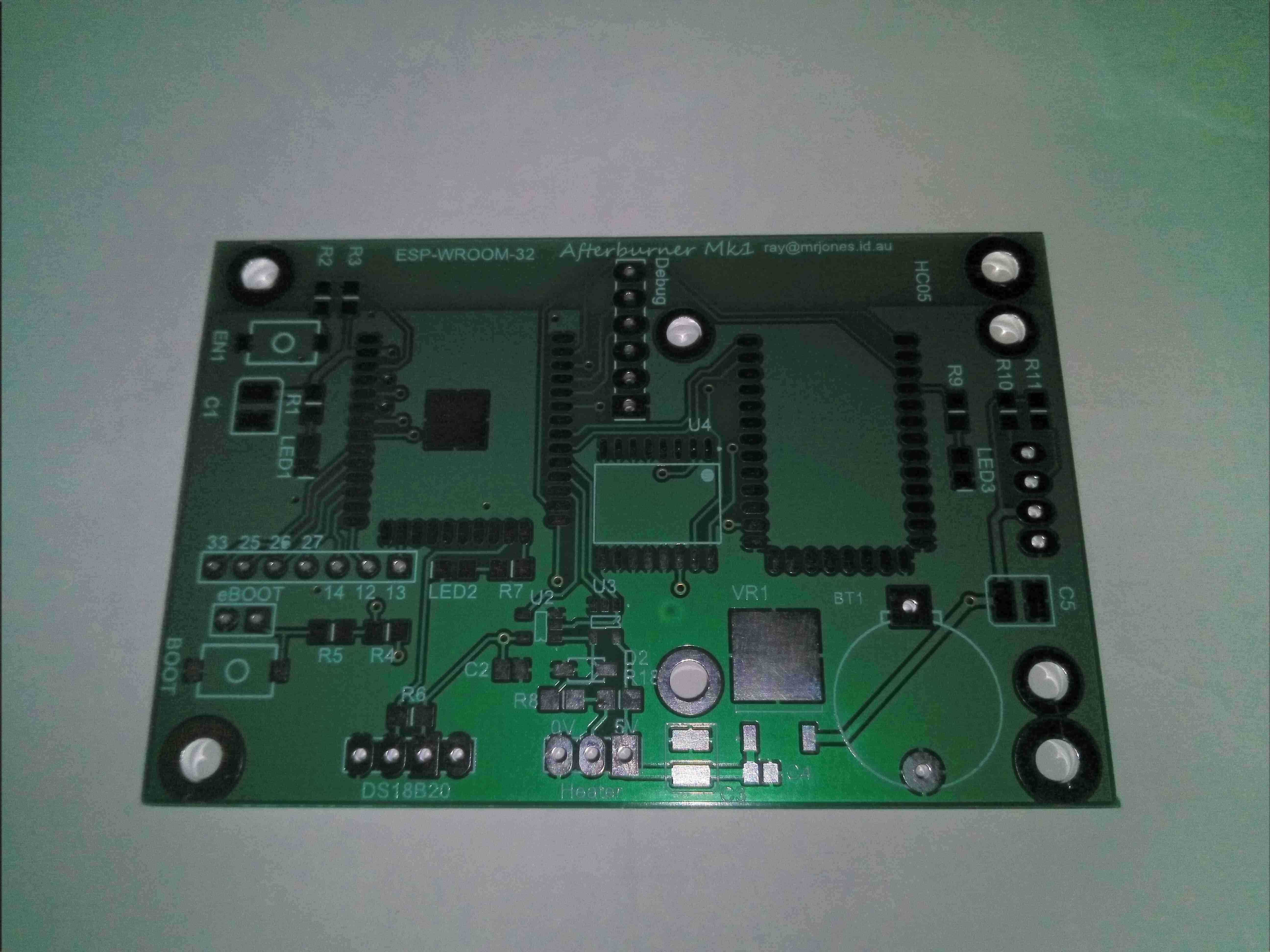
Bare PCB
Here’s the bare PCB kindly sent to me by Ray down under to get this project kickstarted. No THT components here apart from headers, everything is minimum 0805 size.
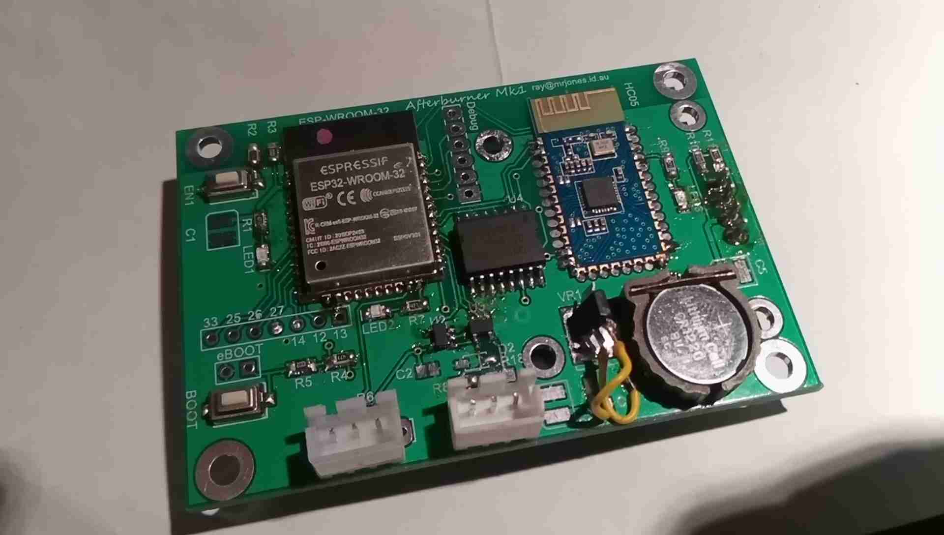
Populated PCB
Here’s the controller PCB fully populated, with the ESP32 & Bluetooth HC-05 modules on board. There was a slight issue with the 3.3v regulator not matching the pinout of the PCB, so some minor bodge work required there, but the current draw of the unit is so low that the regulator doesn’t get warm, even with the heatsink tab floating in mid-air. I’ll hot-snot this down to avoid any vibration issues. Incedentally, soldering the castellated connections of the modules is a real pain – problems with contacts not wetting first time were an issue here. Use plenty of flux!
The two JST connectors are for the main heater loom, and an external temperature probe that feeds back for the thermostat mode of the controller. Reset & Bootloader buttons are provided on the board for easy firmware loading. There’s also some spare GPIO broken out for other uses, along with the required UART port for firmware & debugging access. The clock is maintained by a DS3231 RTC IC, which oddly enough is expensive on it’s own – buying an Arduino RTC module & using a hot-air pencil to desolder the IC worked out £4 cheaper than buying the IC direct! The RTC is backed up by a lithium coin cell.
The communications interface is taken care of by a couple of single gates in SOT-23 packages, which interfaces the 3v3 ESP32 with the 5v signalling levels of the heater’s control bus. This unit is a little odd for a communications interface – it is standard serial, but at an odd baud rate of 25,000, and instead of separate TX & RX lines, the transmissions are gated for TX & RX down a single wire. I fail to understand the logic of doing this, since wire isn’t expensive & extra components just add complexity!
A couple of build notes on this controller:
R4 & R5 are swapped on the silkscreen. Bootloader issues ensued!
The blue PCB Bluetooth module doesn’t function correctly with the controller, allowing receive but no transmit. Odd.
There are two pinout variations on the 1.3″ OLEDs. This layout requires the GND pin leftmost.
PCB Front
The front of the PCB holds the OLED display panel, and the control button array. Not much else on this side of the board besides the RTC battery switching diodes & some passives.
Glow Plug Heating
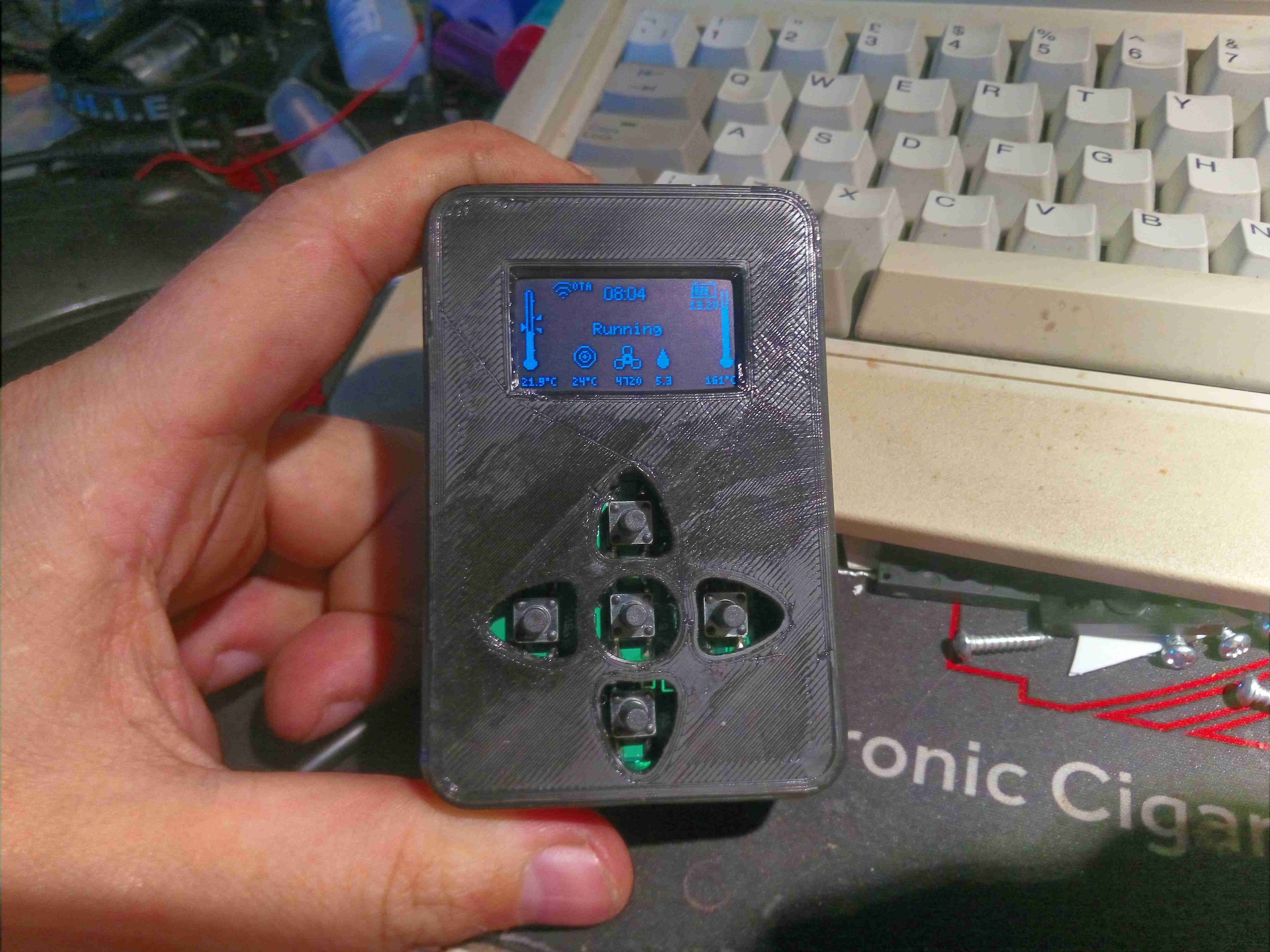
The case to house the PCB is 3D printed, I didn’t bother with the matching buttons as I don’t currently have any flexible filament to print with, so long stem tact switches are used. The controller is running the heater through a cycle here on the Detailed Info screen, where the most comprehensive heater info is displayed. In this stage, the heater’s ECU is warming the glow plug up ready for ignition.
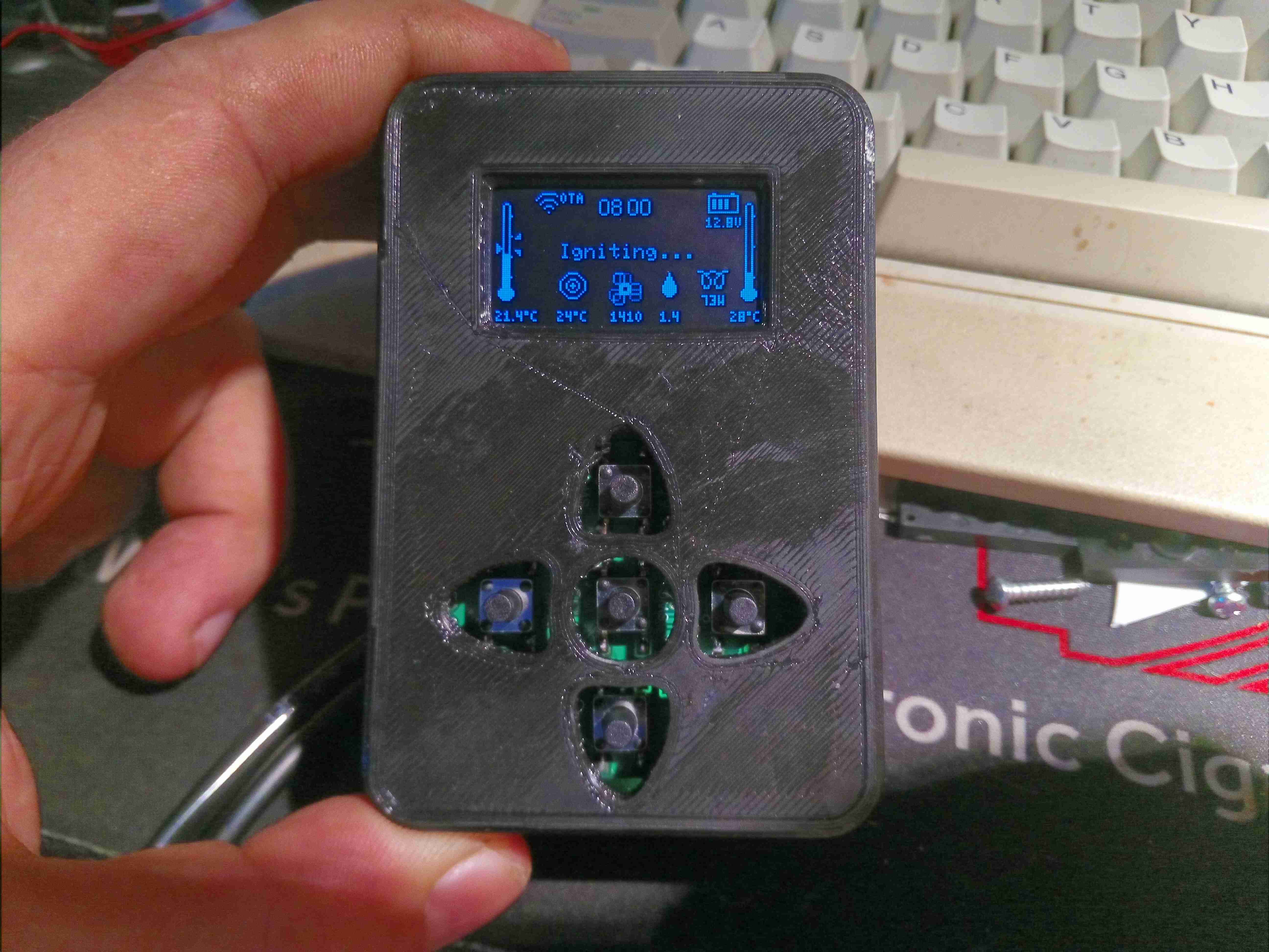
Igniting
After the glow plug has heated, the ECU starts the fuel metering pump at it’s lowest rate to get a flame going. The glow plug is still active to vaporise the fuel.
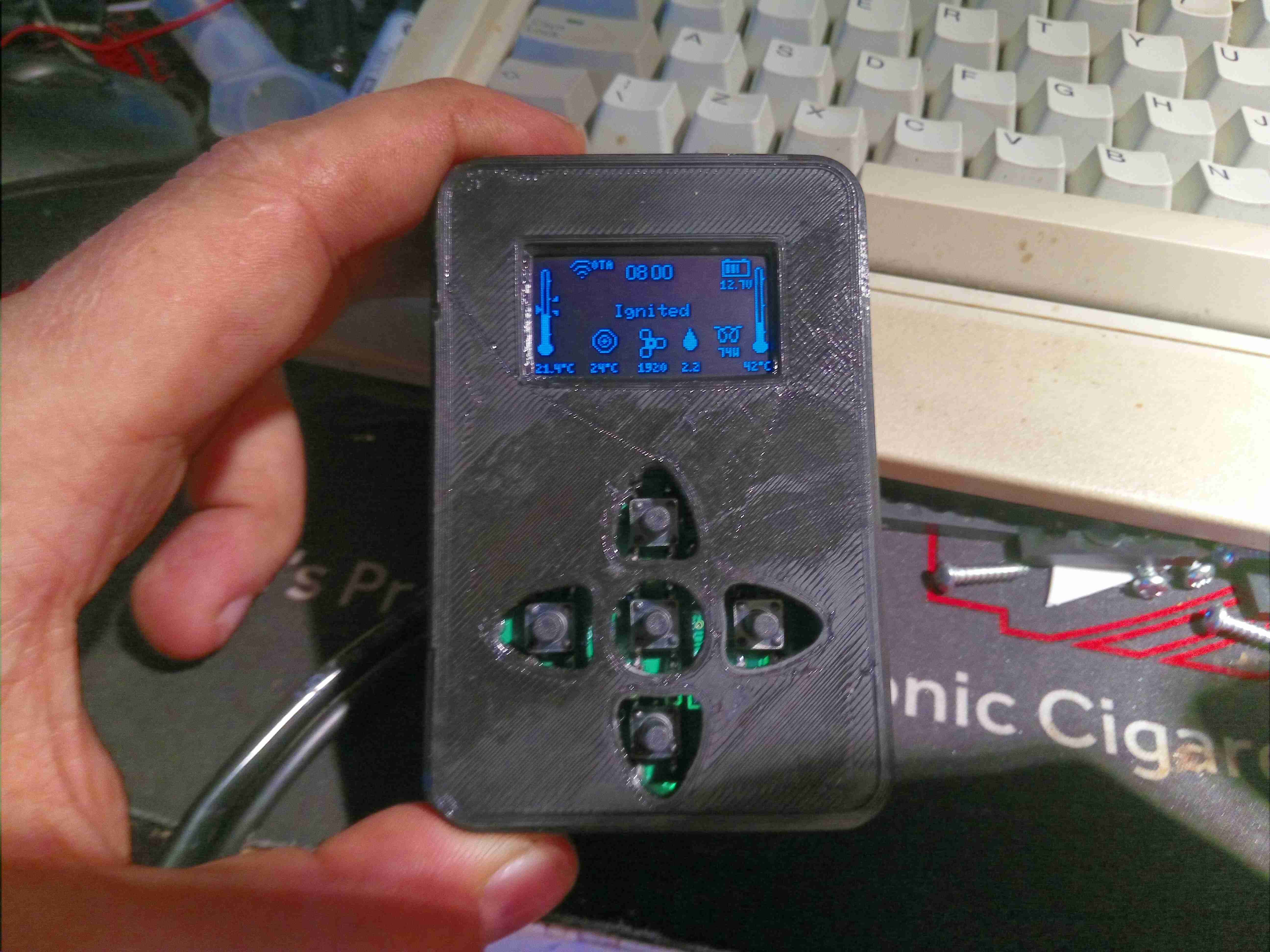
Burner Running – Heatup
Once the thermistor on the heat exchanger registers a temperature increase, the ECU detects the burner has lit, and starts increasing the fuelling rate & blower speed.
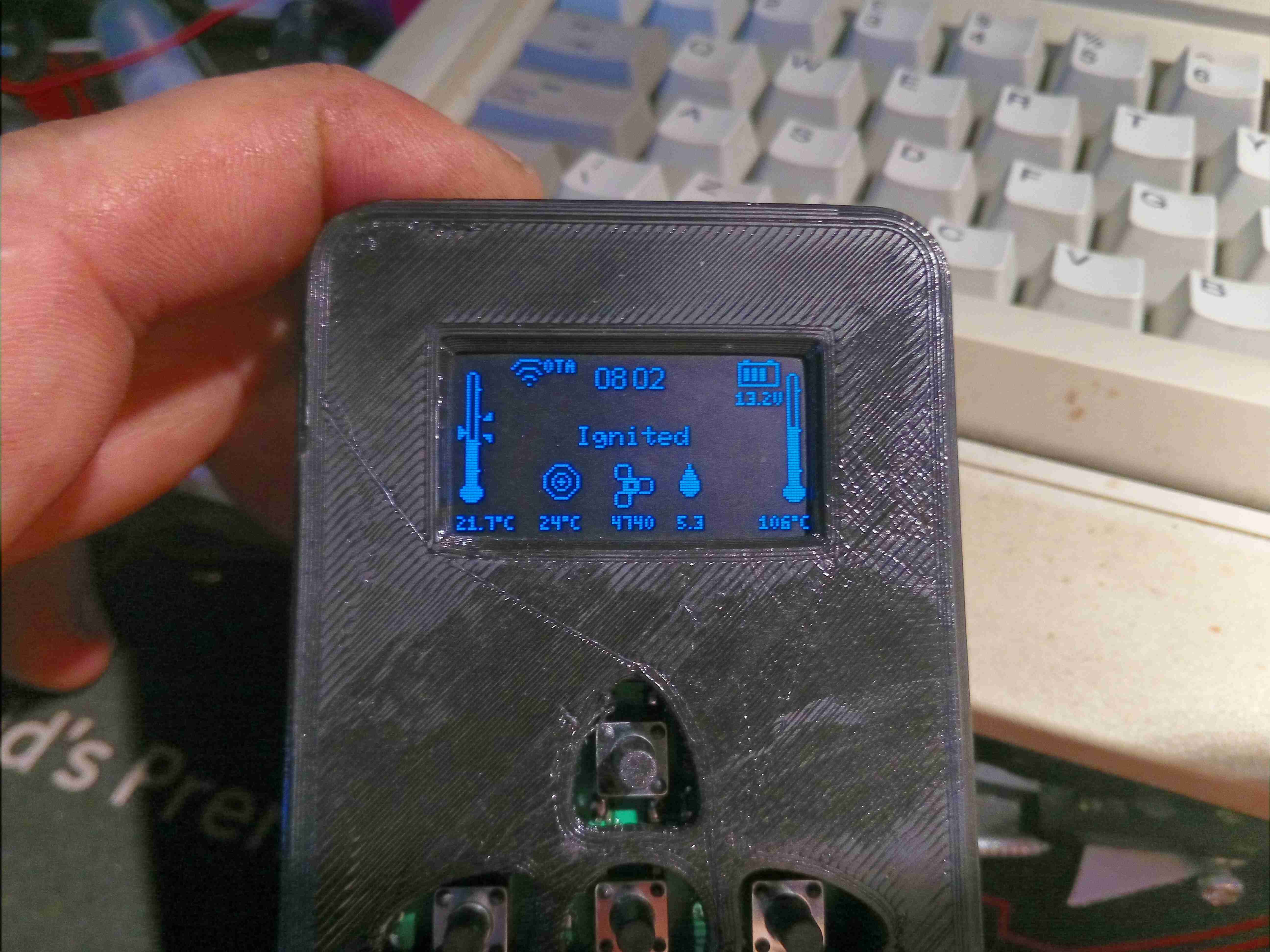
Warming Up
Once the temperature hits a threshold, around 55°C, the ECU switches off the glow plug & ramps the fuelling rate up to max to warm the heat exchanger to operating temperature. The detailed page displays both the room temperature (left), set temperature & heat exchanger temperature (right).
Heater Running
Once the heat exchanger has reached running temperature, the ECU switches control to the thermostat, in this case the new controller.
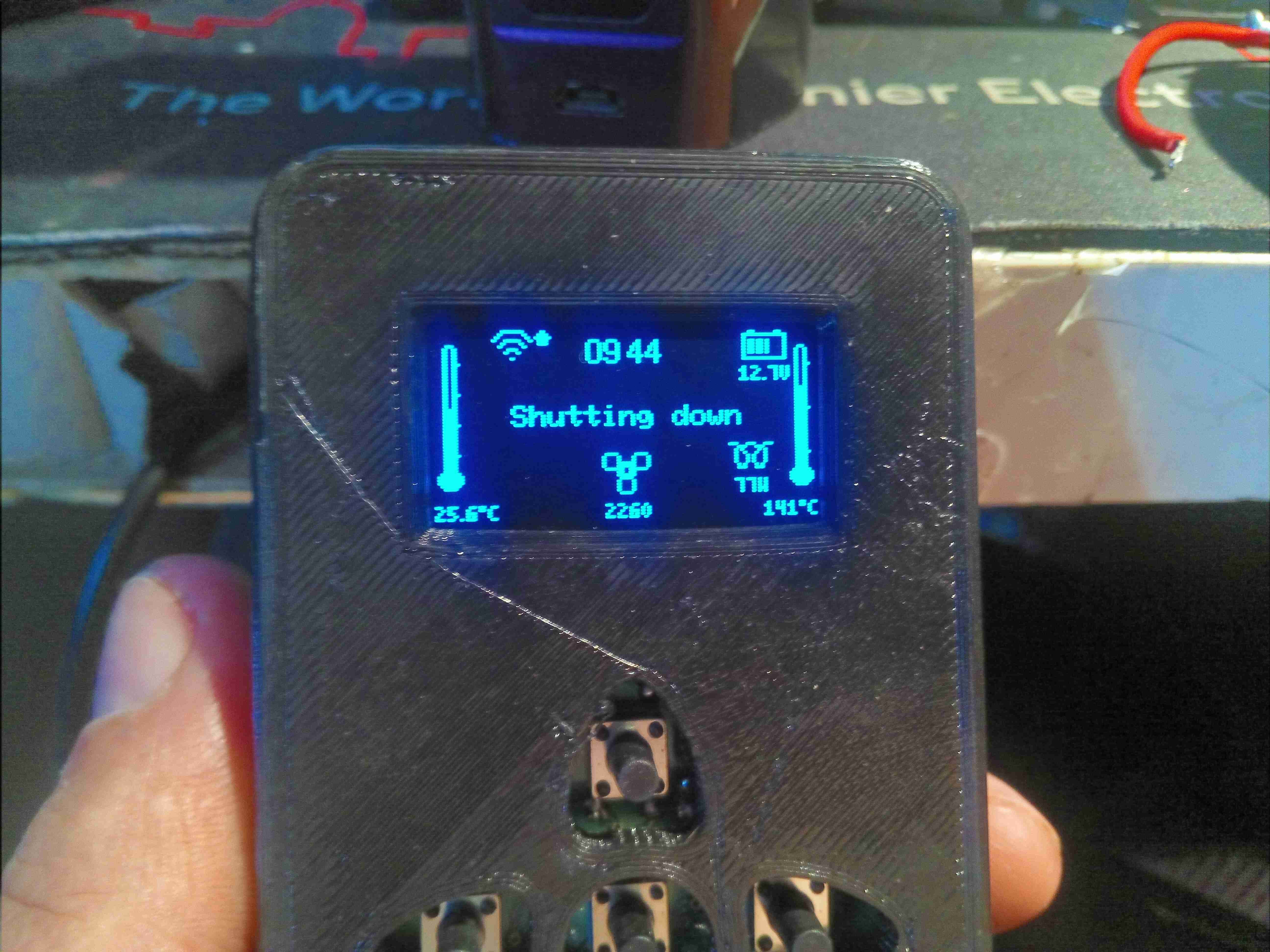
Shutdown
When a shutdown is initiated, the heater brings the glow plug back on & reduces the fuelling rate to minimum for a couple of minutes, before stopping fuel flow. The glow plug remains running for a while to burn off any remaining fuel residue.
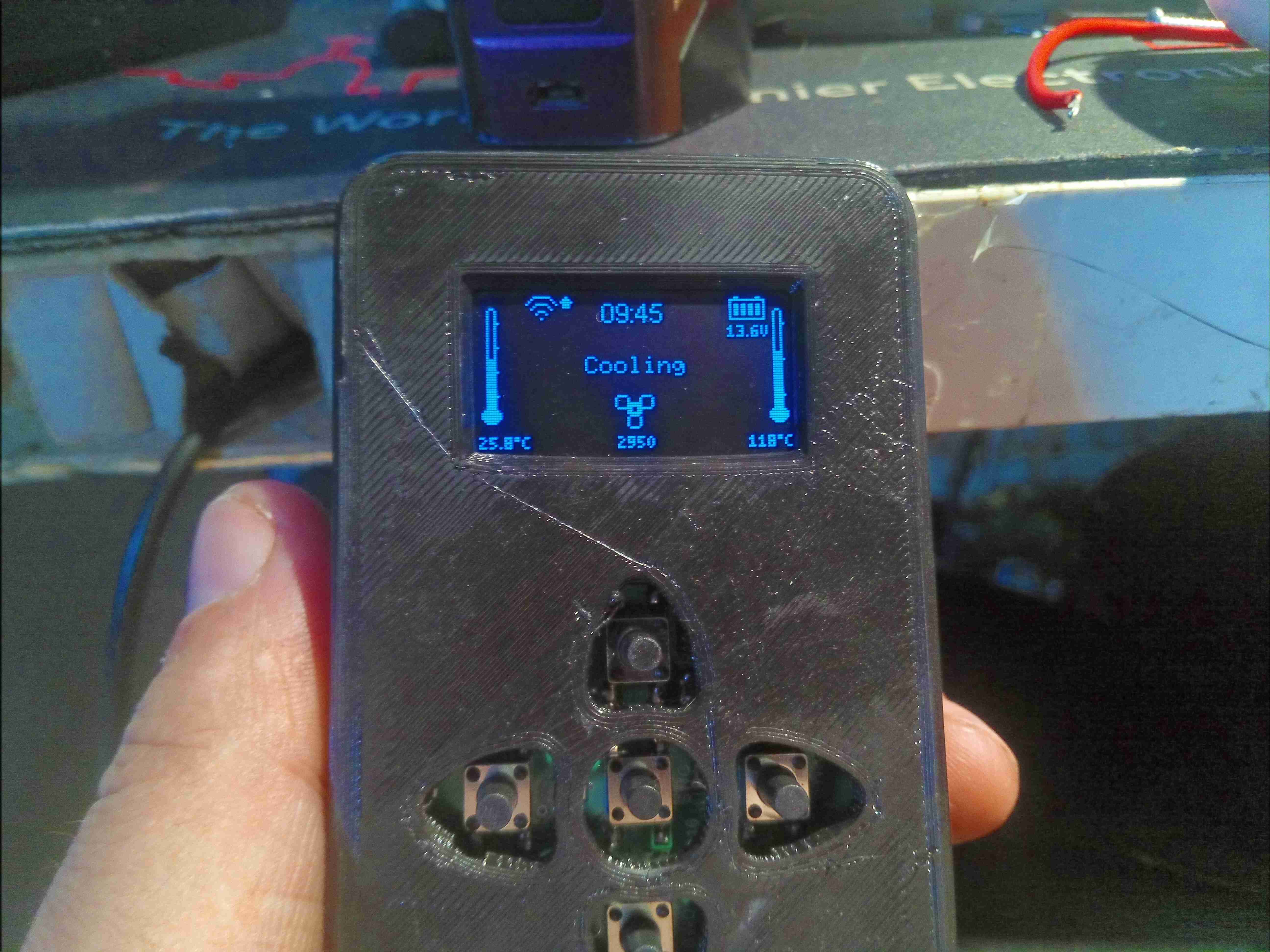
Cooling Cycle
Finally, the ECU cuts power to the glow plug, and keeps the fan running at medium speed until the heat exchanger cools to below 55°C.
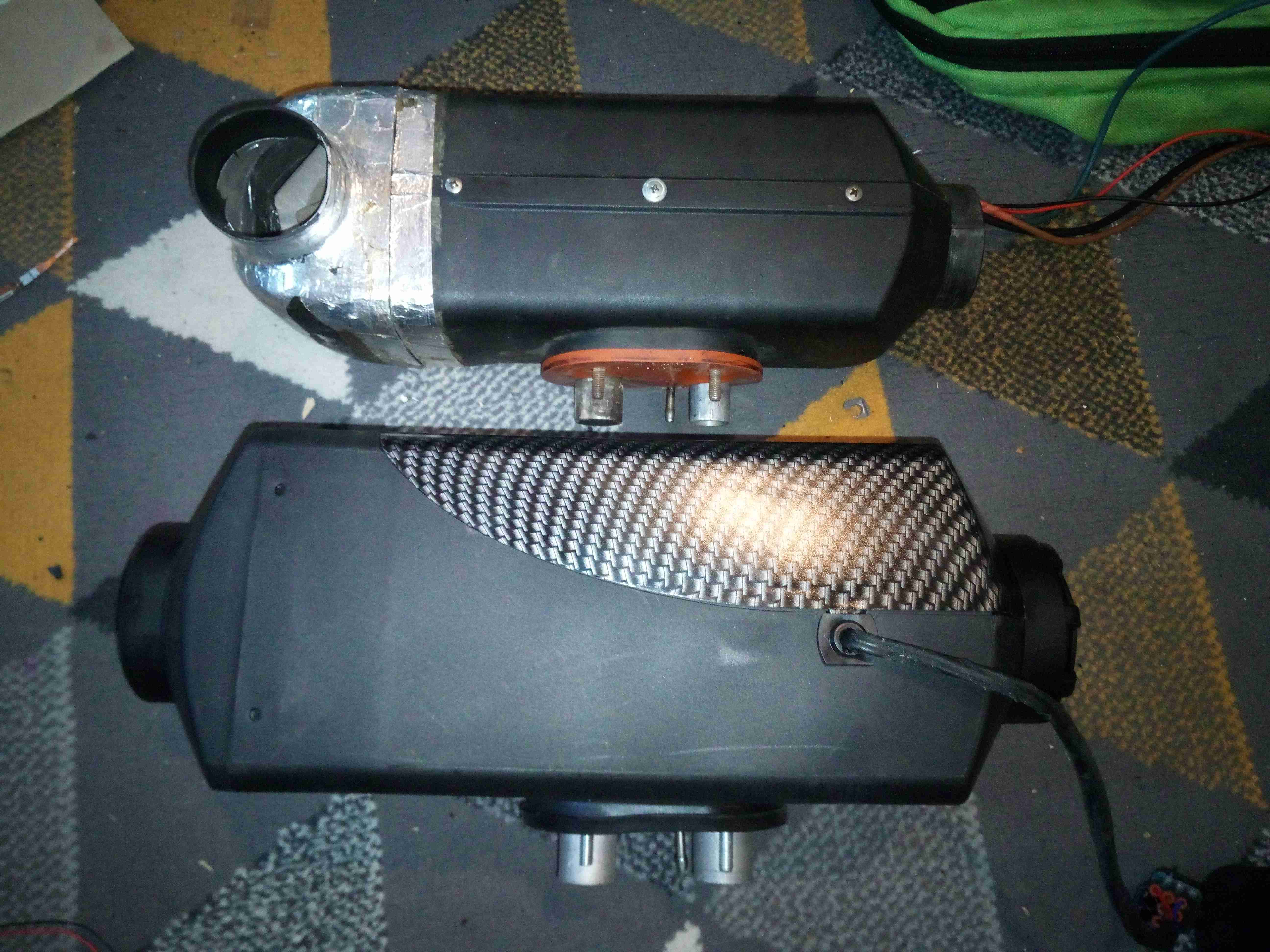
As part of the giant power bank that gets dragged to all my major camping trips & festivals, there is an old Eberspacher Diesel heater, a D1LCC from at first guess somewhere in the mid 90’s. At only 1.8kW heat output this is a little small for our current tent, and it struggles to keep the temperature comfortable at night, so with Chinese clones on the market these days much cheaper than the Eberspacher or Webasto units, a replacement was up! Still, the old Eberspacher is in working order, and will probably get used for some other project.
Diesel Heaters
After removing the old D1LCC & placing it next to the new one, the size difference is obvious! The new heater is a Chinese clone of the Eberspacher D4 unit, allegedly uprated to 8kW. (In reality, it’s probably around 5kW heat output at full tilt). Luckily, it’s not that much larger than the old one, so it’ll go into the same space.
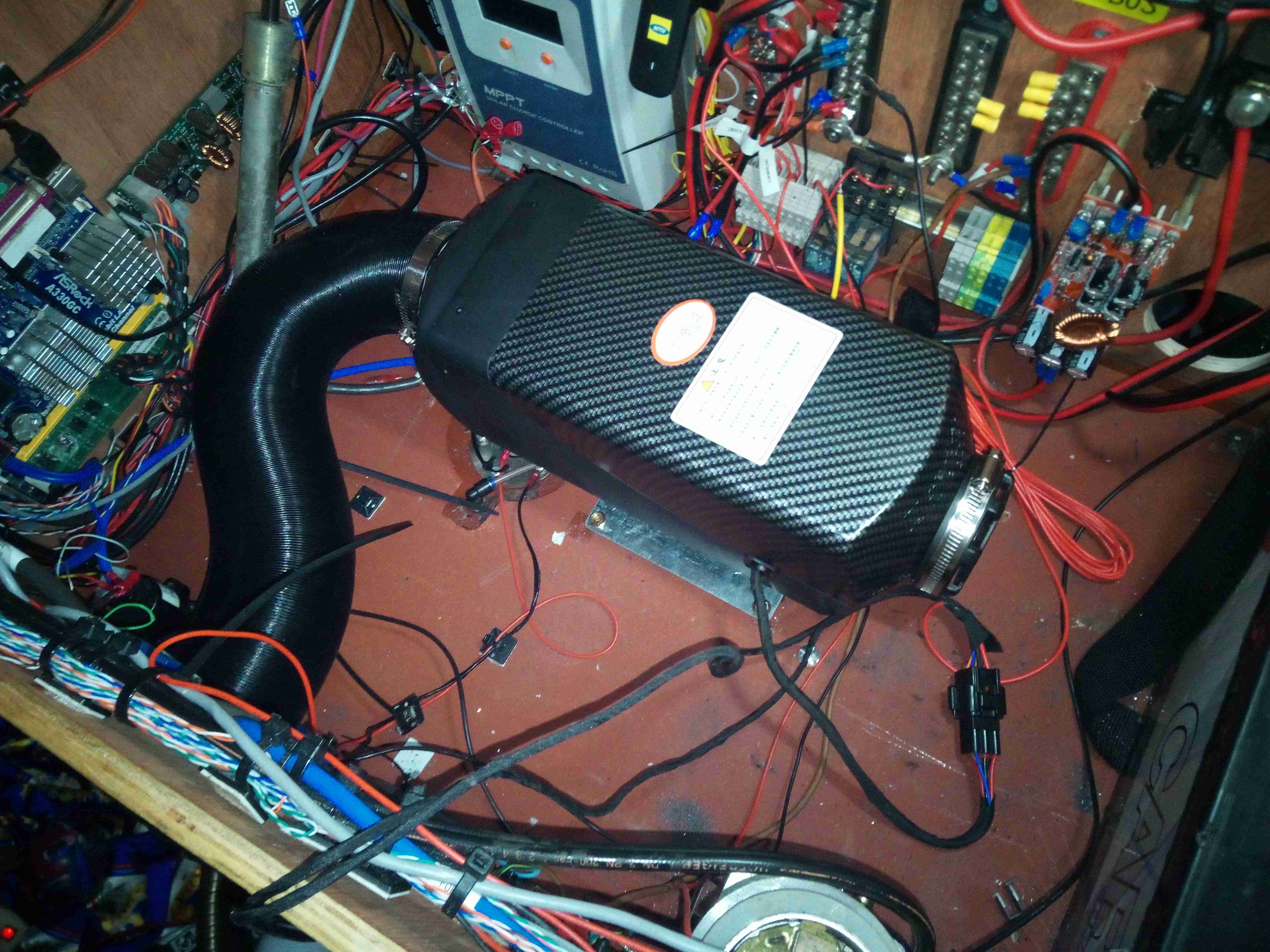
New Heater
The port layout on the bottom of the heater is identical apart from intake port size, a quick attack of the baseplate with a grinder to remove the old hole pattern allowed the supplied mounting plate to fit correctly into place for the new heater. The duct size on this unit is also bigger than the old 60mm – 75mm duct is used on these large units. No modification to the vent hole was required, as the 75mm vent already fit perfectly. To clear the fittings on the top of the fuel tank, which is just underneath the hot air exhaust cowling of the heater, the mounting plate is fixed using 10mm nylon standoffs, this also helps get a bit more natural airflow around the base of the heater, as the mounting gets to 90°C in operation at full power!
These heaters don’t use the Eberspacher standard switch wire for control – there are only 3 pins in the loom to the controller, for 5v power & an odd UART which uses gated TX/RX to avoid having a separate line for each.
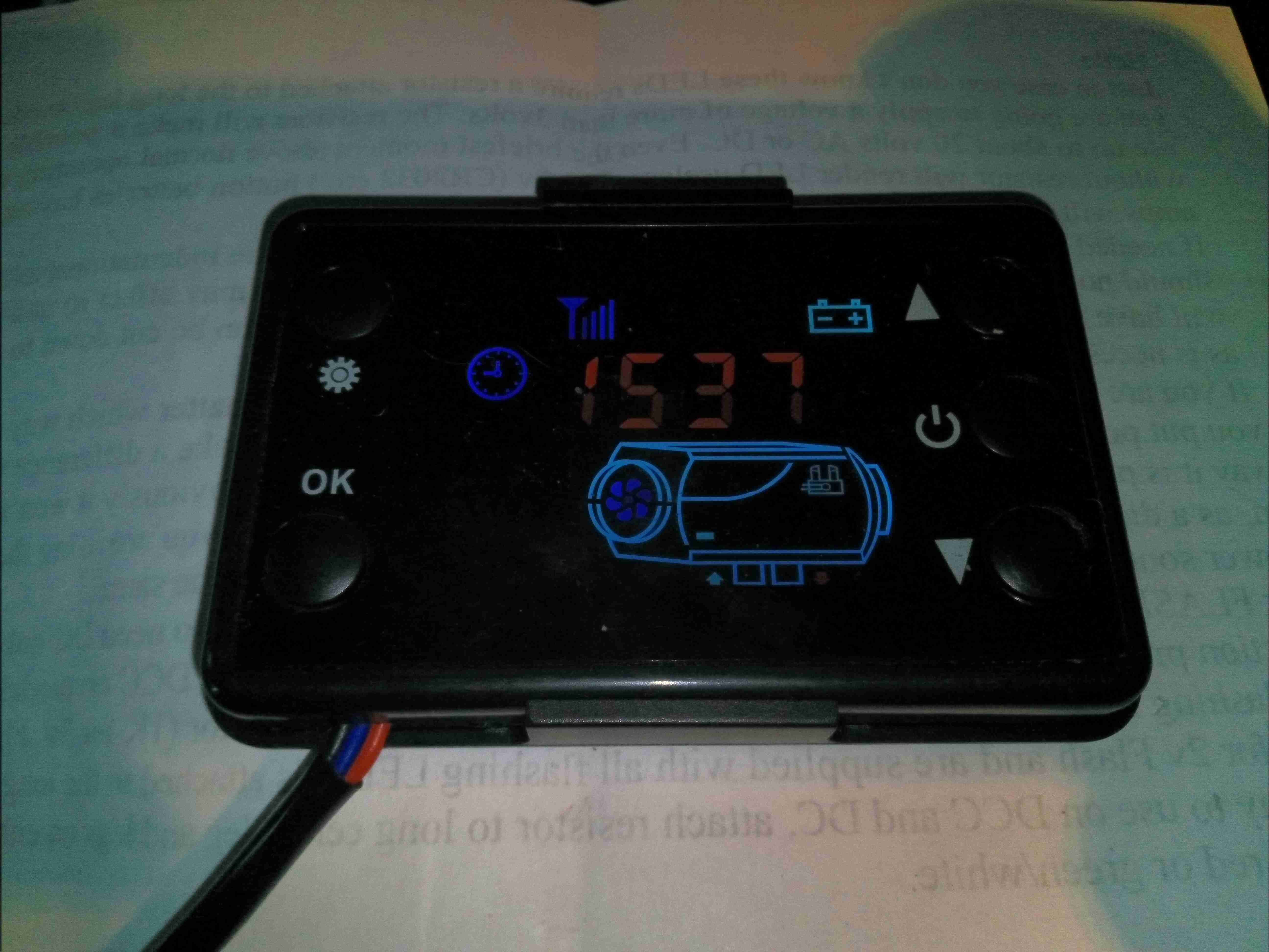
Stock Controller
The stock controller has quite a nice looking LCD display, but it’s less than responsive & the backlight is always on at full tilt. It’s also much larger than the Eberspacher 701 controller so would require some rejigging of the control panel on the trolley. The built-in thermostat is also inaccurate, being almost 5°C high no matter what the room temperature. Ray Jones from Down Under has designed an open source ESP32 based controller for these heaters, and one of these is currently being built to control the unit. More to come on this bit!
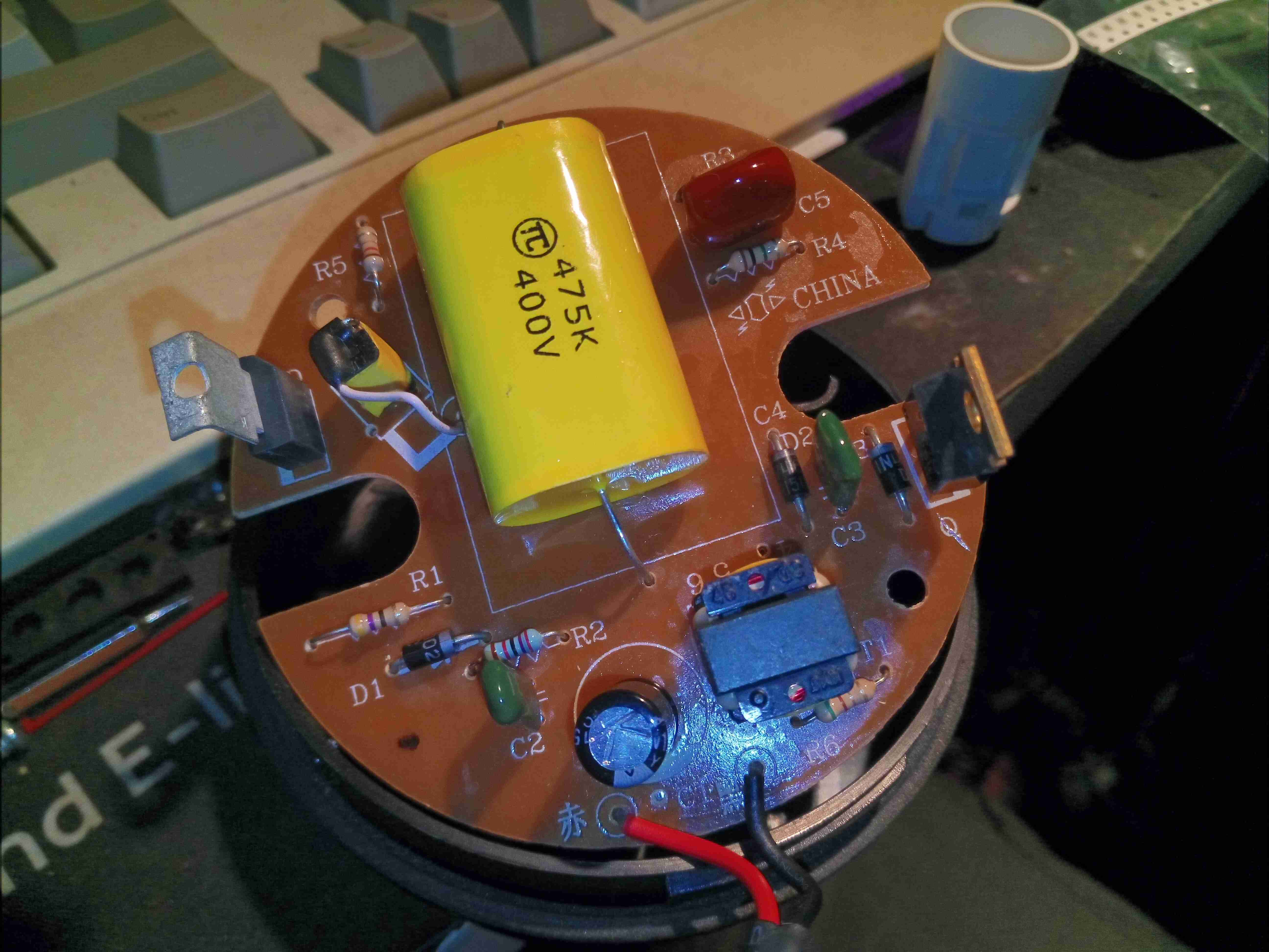
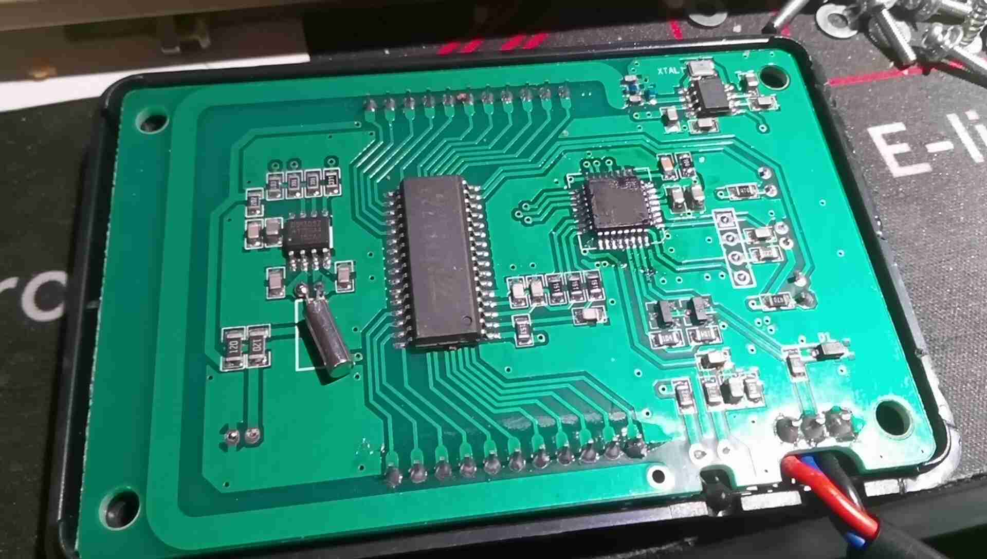
Stock Controller PCB
A quick teardown of the controller reveals pretty simple internals, there’s a microcontroller, probably an STM8 device by looking at the programming header, but the markings have been scrubbed off the IC. There’s a standard LCD controller IC, a RTC which isn’t battery backed, and a 433MHz receiver IC with PCB trace antenna.
I wasn’t able to get the remote control function working with any of the remotes I have, any attempt at pairing a remote didn’t give any response from the controller unit. I also tried a 315MHz remote, but that didn’t work either. Not an issue since I’m building a much better open source controller.
Fuel & Exhaust
Under the base is the exhaust system & the fuel dosing pump. There’s a small filter in the feed line from the tank to keep crap out of the pump, and nylon fuel line then runs the fuel to the heater inlet. The exhaust is made as gas-tight as possible with foil tape & exhaust paste, to keep the exhaust fumes contained in the pipework until they’re vented outside. The rest of the exhaust after the right hand silencer is done in brazed 22mm copper pipe, and a piece of Eberspacher exhaust duct is removable from the final exhaust tail for storage. The black pipe is the combustion air intake, which is simply fed into a silencer cable tied to the trolley frame.
Heater Ports
The 3 ports are visible under the mounting plate, the square hole cut out of the trolley base to accommodate everything.
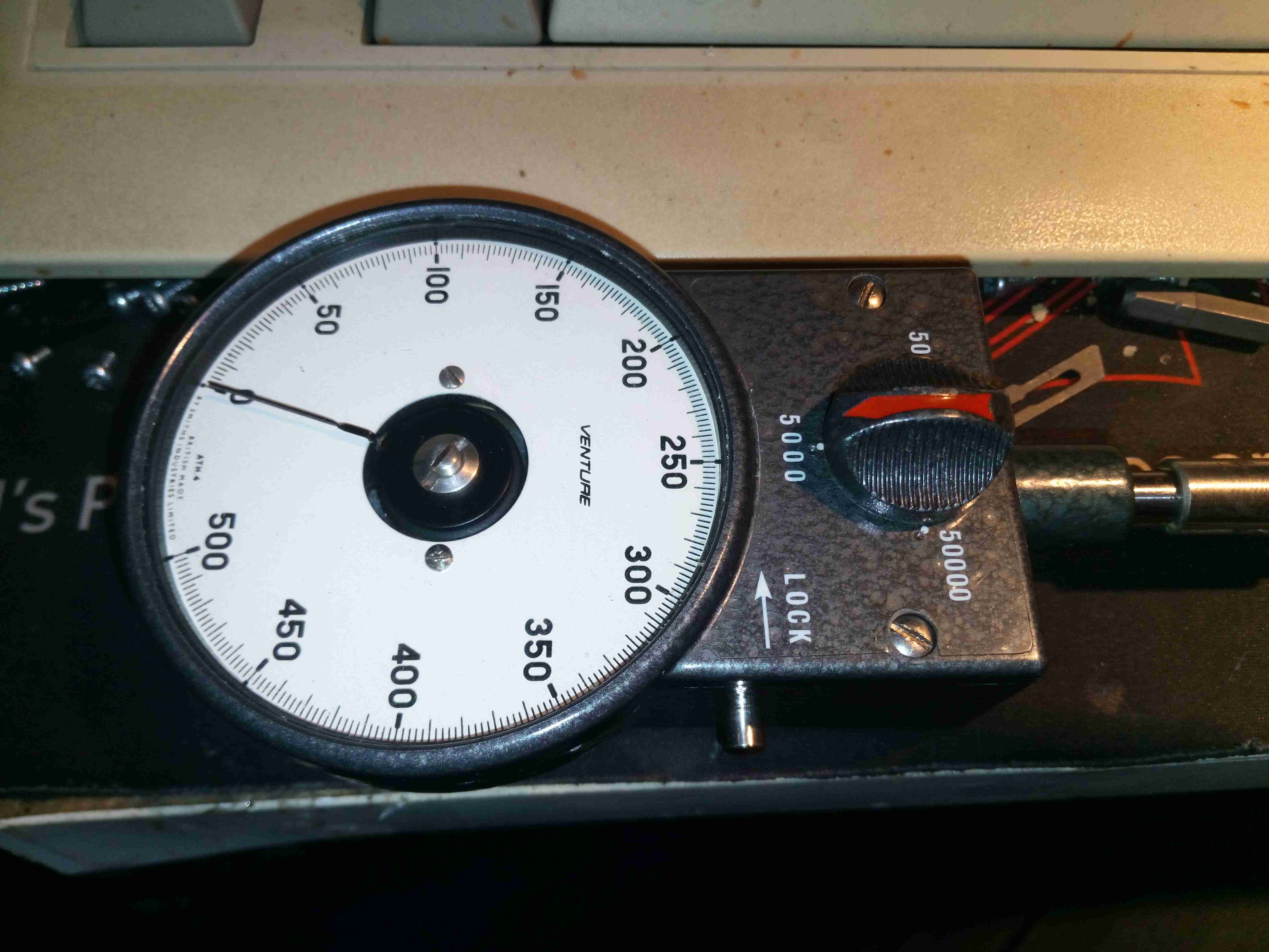
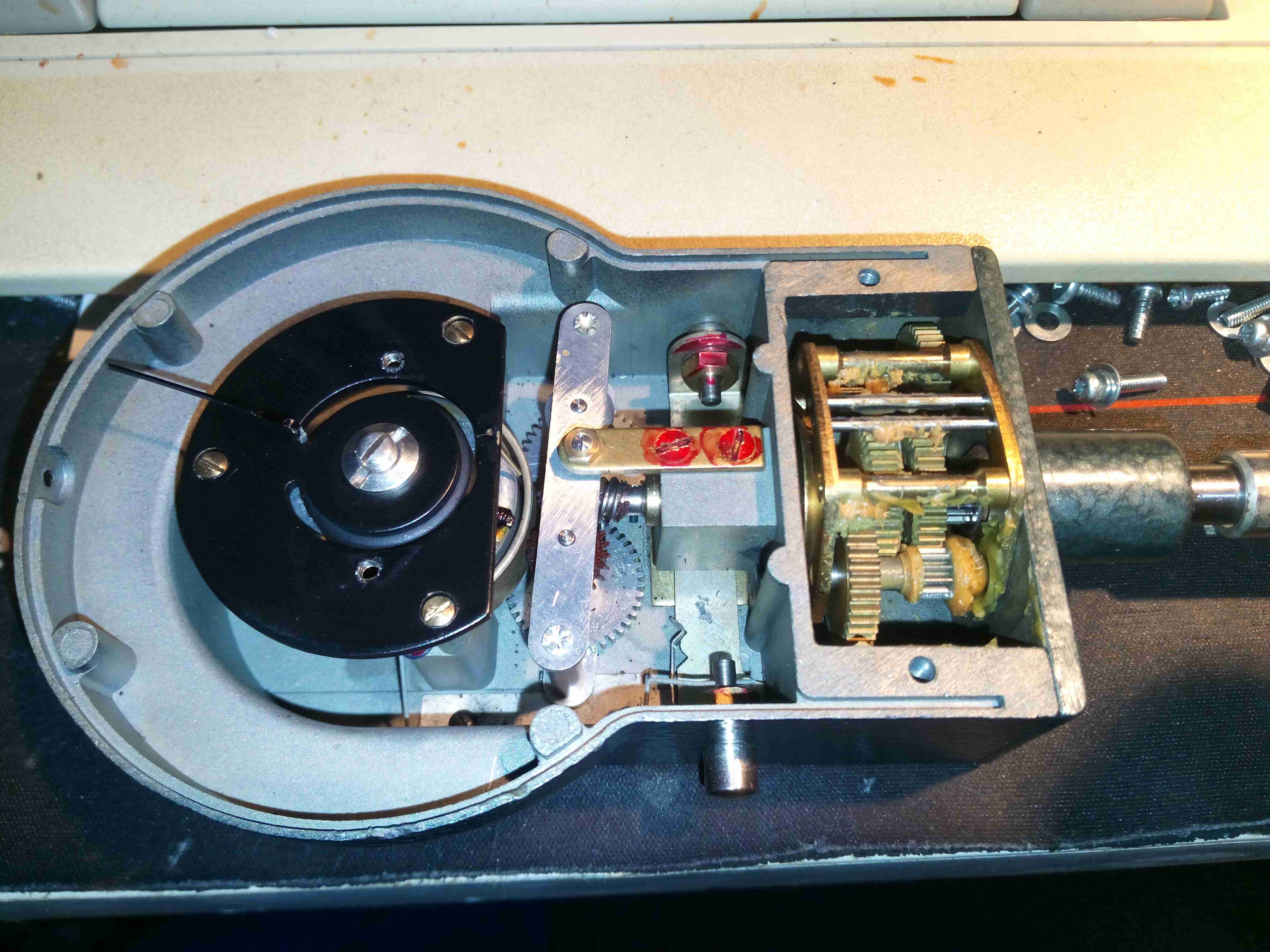
Quite a nice skip find this – it’s a mechanical tachometer from Smiths, the Venture ATH4. Scaled to run to 50,000RPM in x1, x100 & x1000 scales this is quite a nice instrument. Input drive shaft is on the right, with the scale selection knob & pointer lock. Mechanical eddy-current movement is on the left.
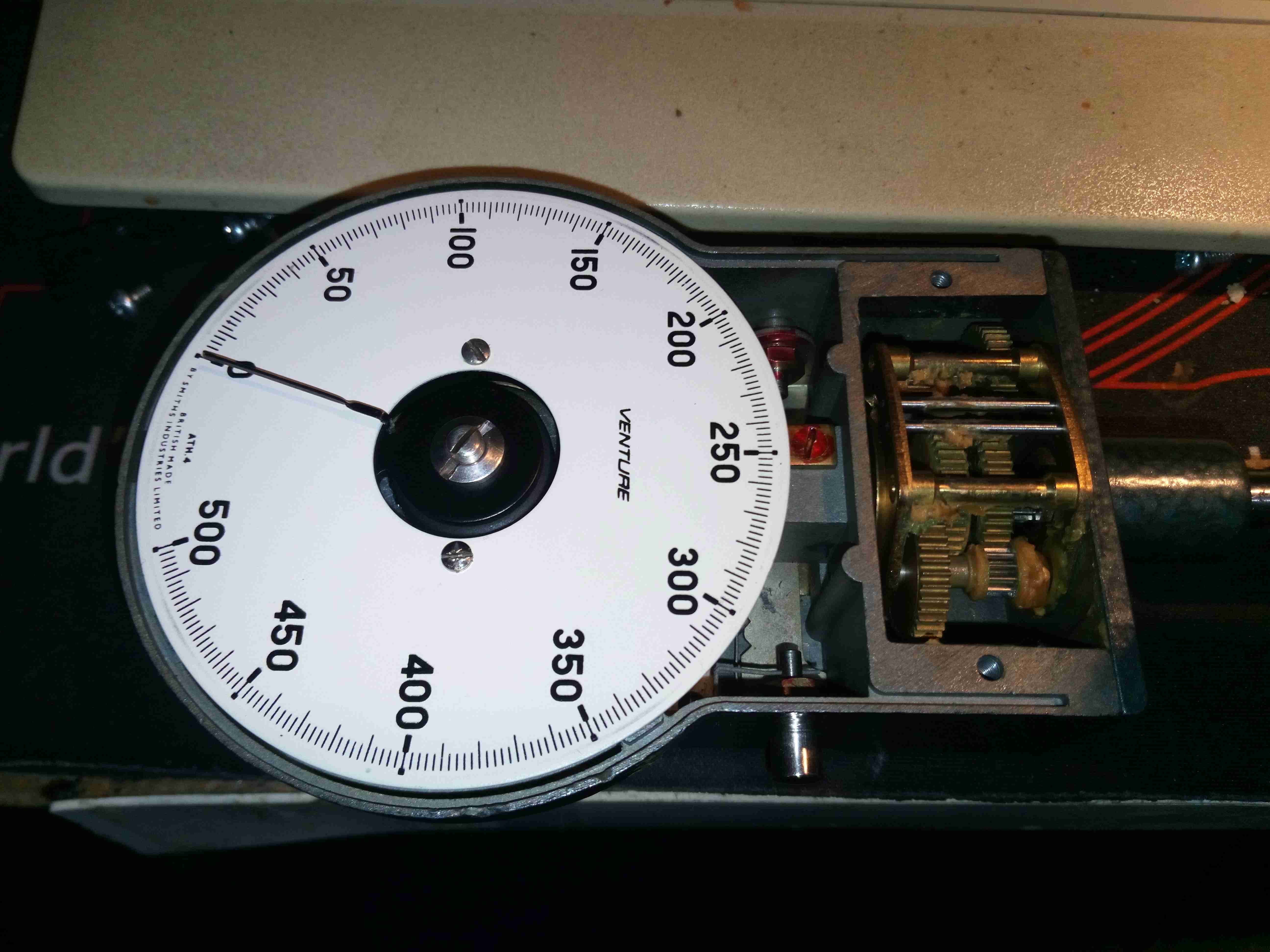
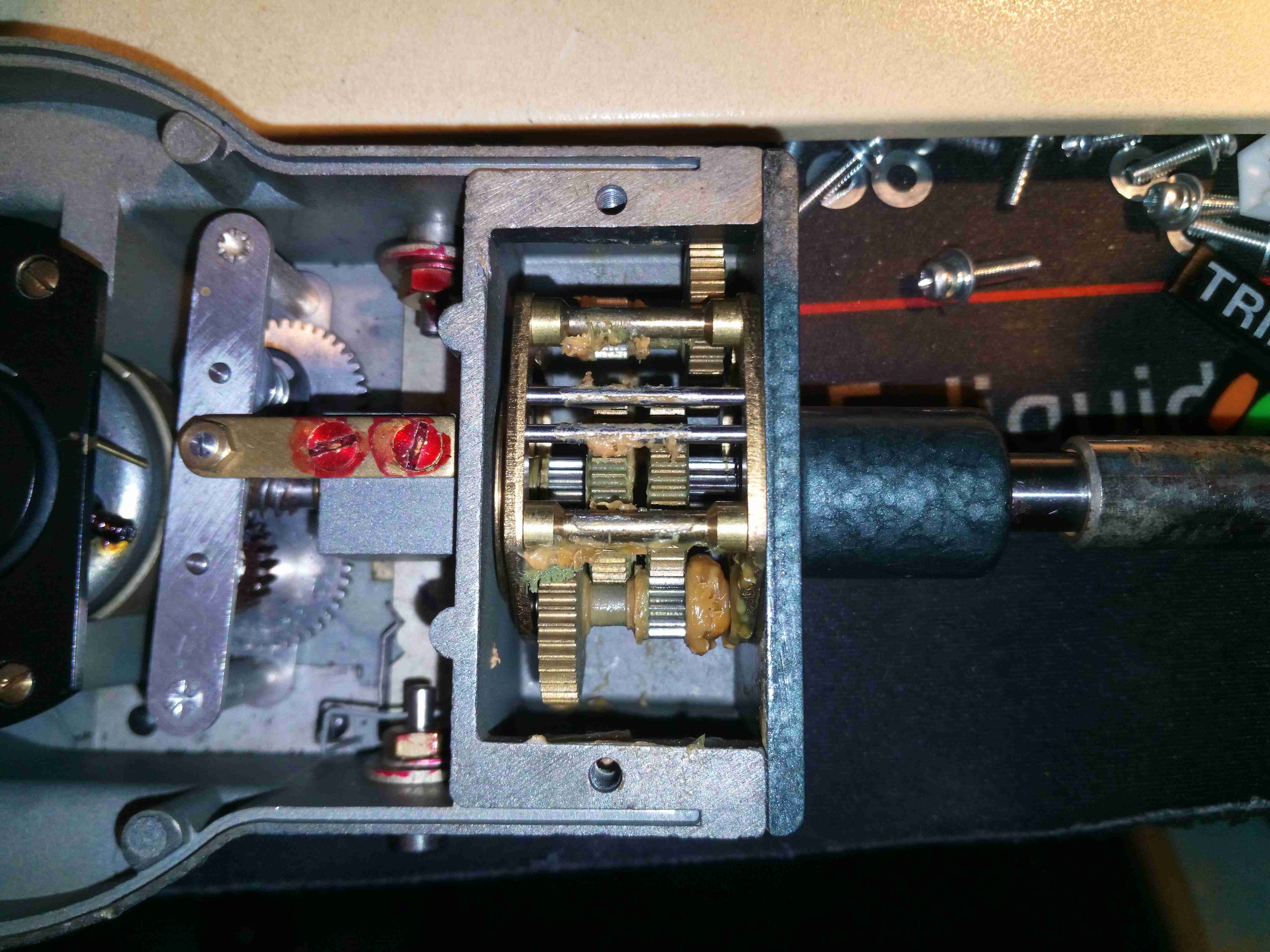
Top Cover Removed
3 small screws allow the front cover with the crystal to be removed from the movement. Calibration is done with the adjustment in the centre of the movement itself, which will alter the tension on the hairspring. The ranging gearbox is on the right side, full of old hardened grease which I’ll probably clean out & replace with fresh.
Bare Mech
With care it’s possible to remove the scale face without harming the movement or the very fine needle, this shows the remaining part of the mechanical drive. The see-saw after the gearbox is the reversing drive, so that the needle moves regardless of the input shaft rotational direction.
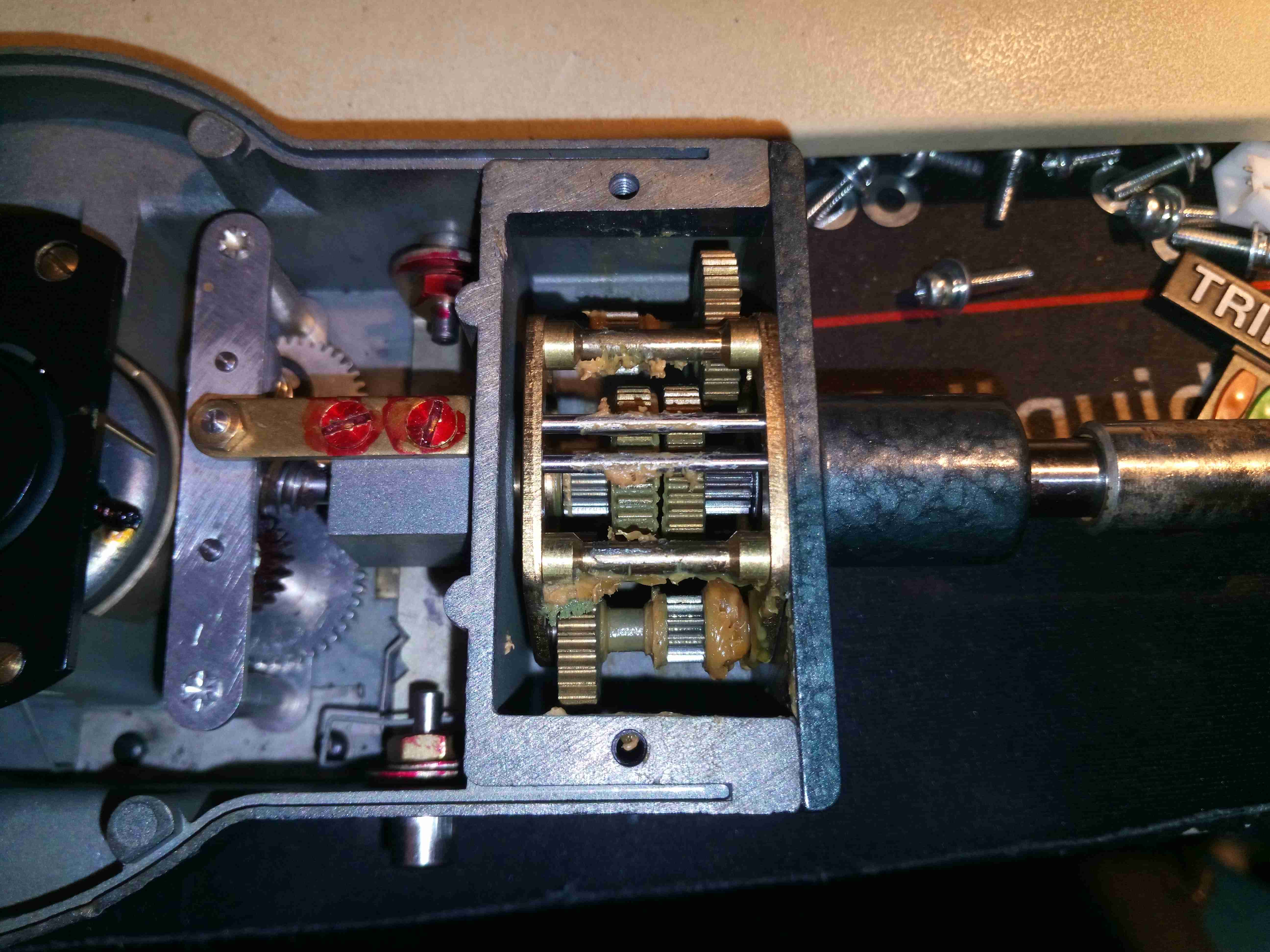
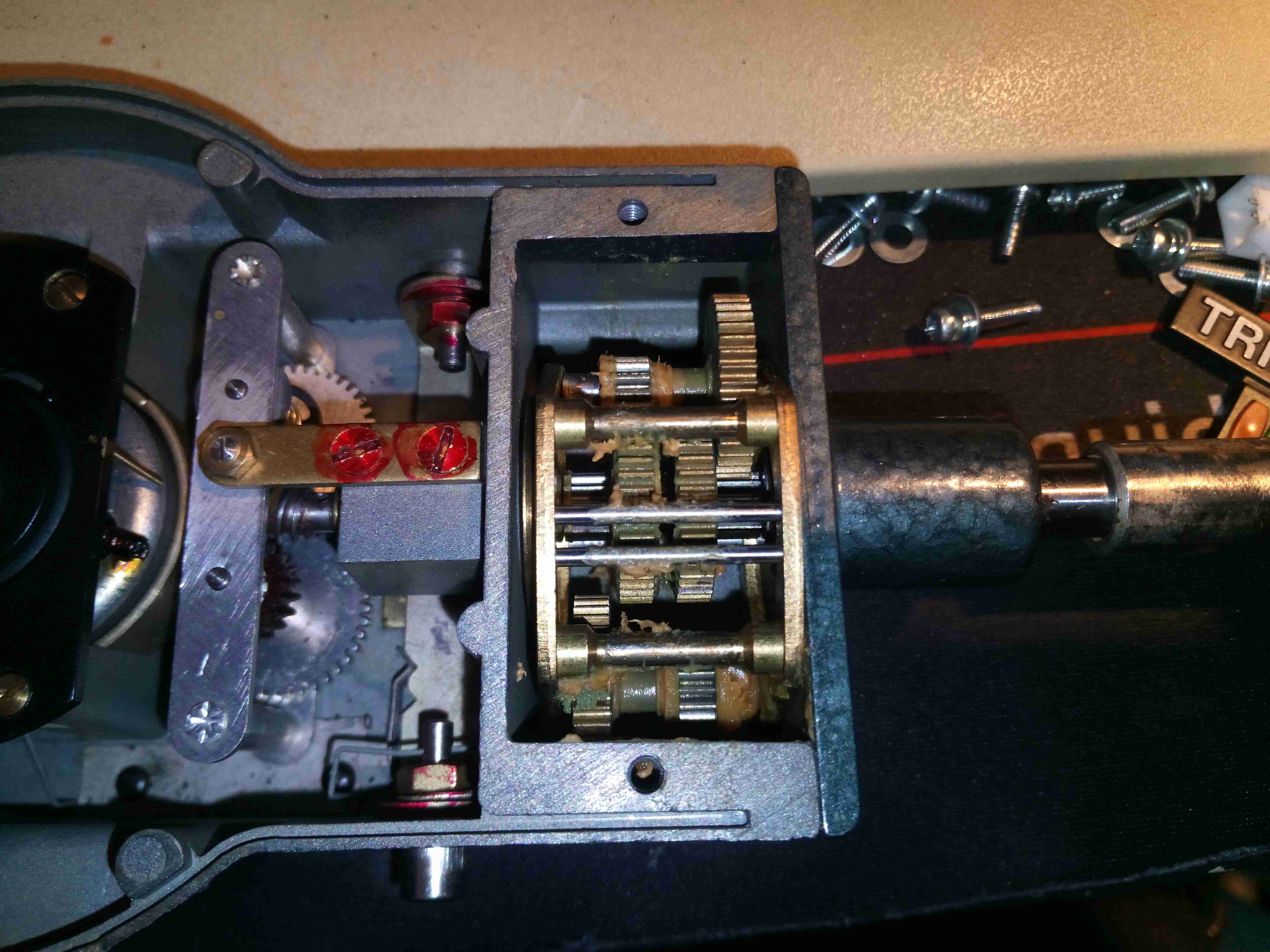
Low Gear
The ranging gearbox is very neat. It has 3 different gear ratios for the different ranges – here it is in the 500RPM position, which effectively gears the input drive up to drive the movement faster.
Mid Range
On the mid scale of 5000RPM, the gearbox reverts to direct drive into the movement, by pushing the input & output gears together – they both have gods on their faces to facilitate this drive.
High Gear
On the 50,000RPM range, the gearing changes to a reduction drive, slowing down the output to the movement.
Movement Drive
After the ranging gearbox, there’s a final worm-drive reduction, with a fibre gear to reduce friction, and the reversing drive. The alloy bar swings with the forces of the worm drive to keep the drive to the eddy current movement, which is just visible under the black plate, running in the same direction regardless of direction of input drive. The pointer lock is also visible here, as the fine wire under the black plate. This just touches the drag cup to stop the pointer moving.
Amazingly, even though the calibration sticker has this instrument as last calibrated in 1997, it seems to be still perfectly within calibration – I’ll have to compare with a laser tachometer to see how accurate it actually is.
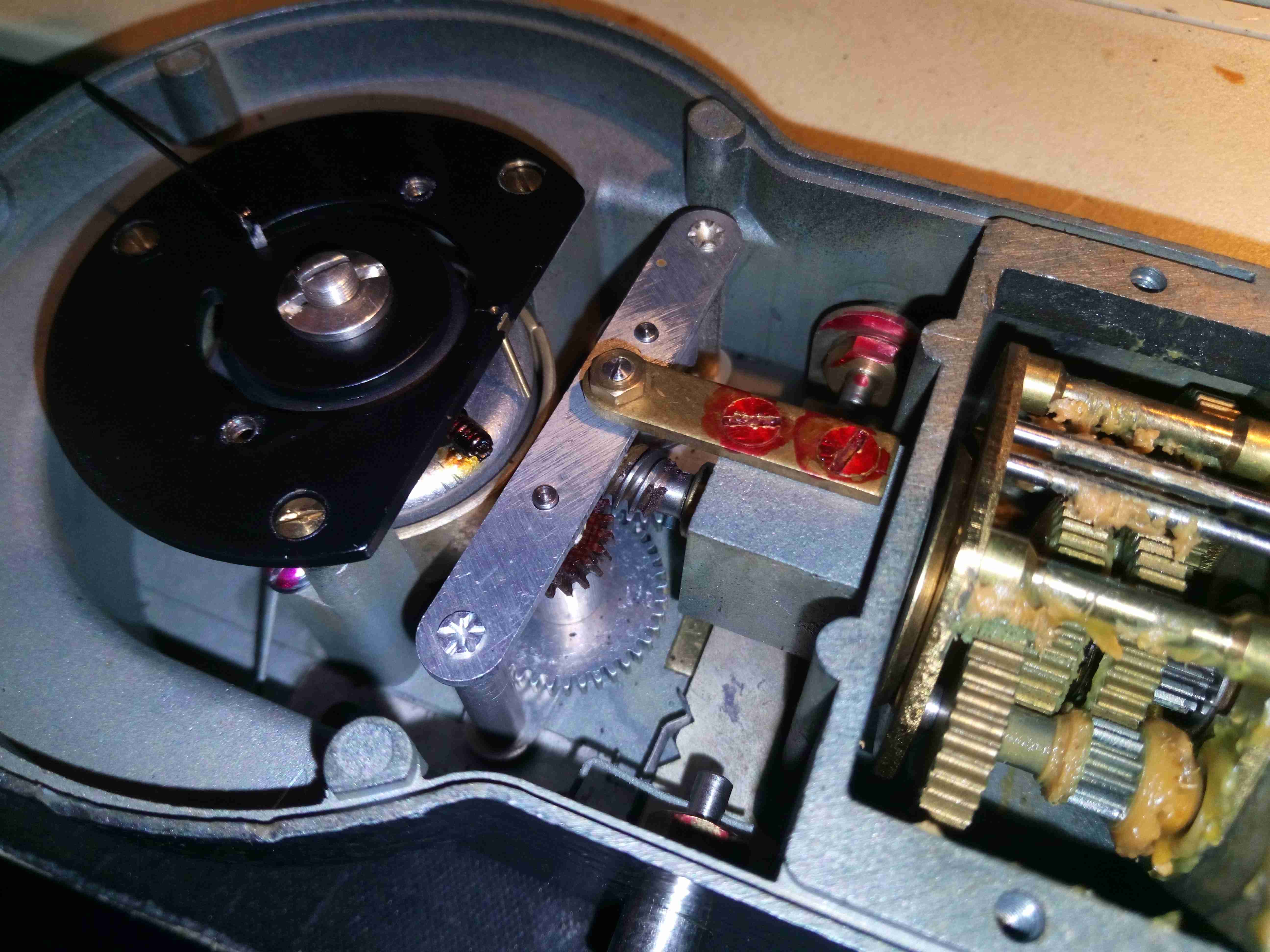
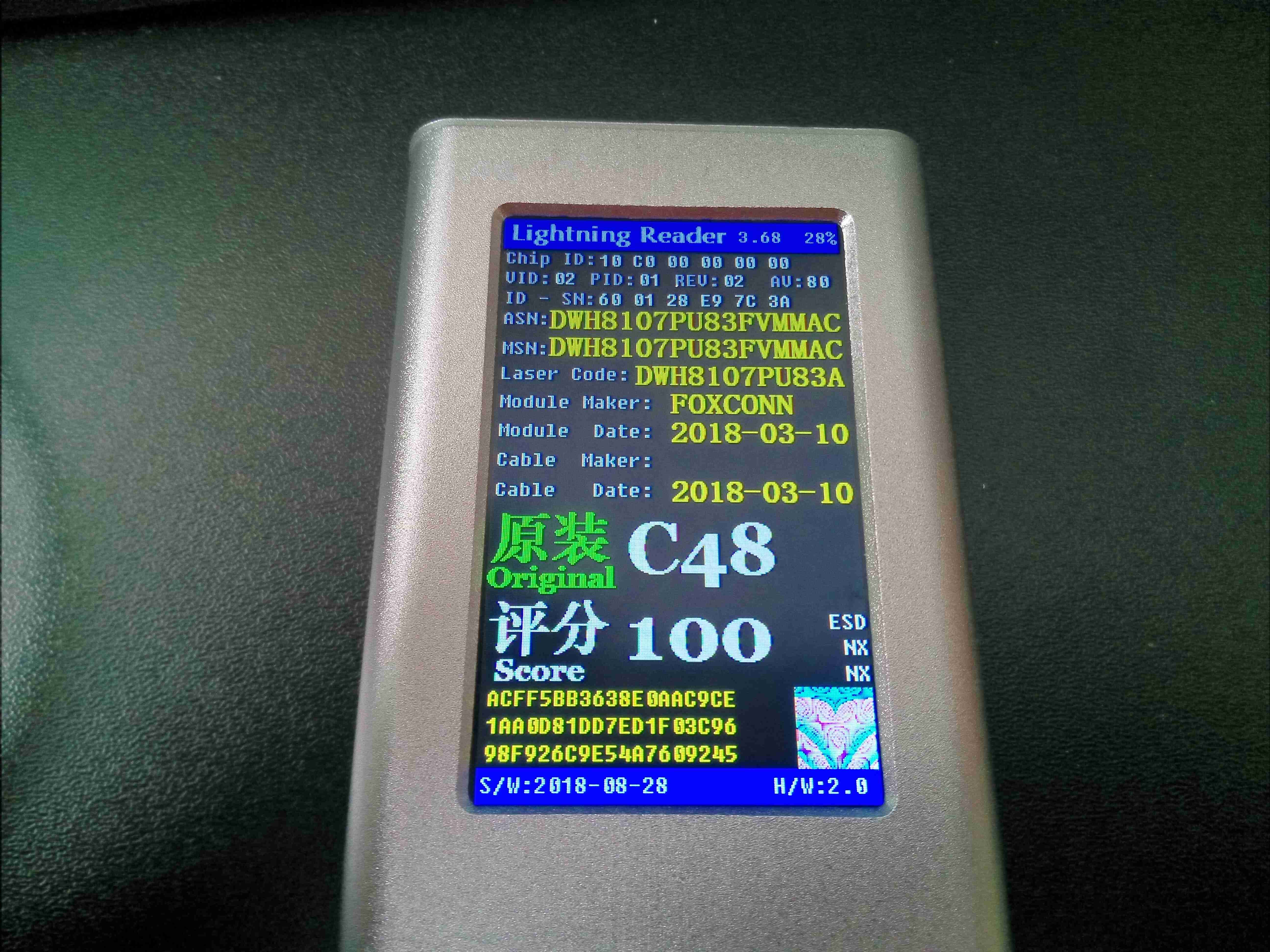
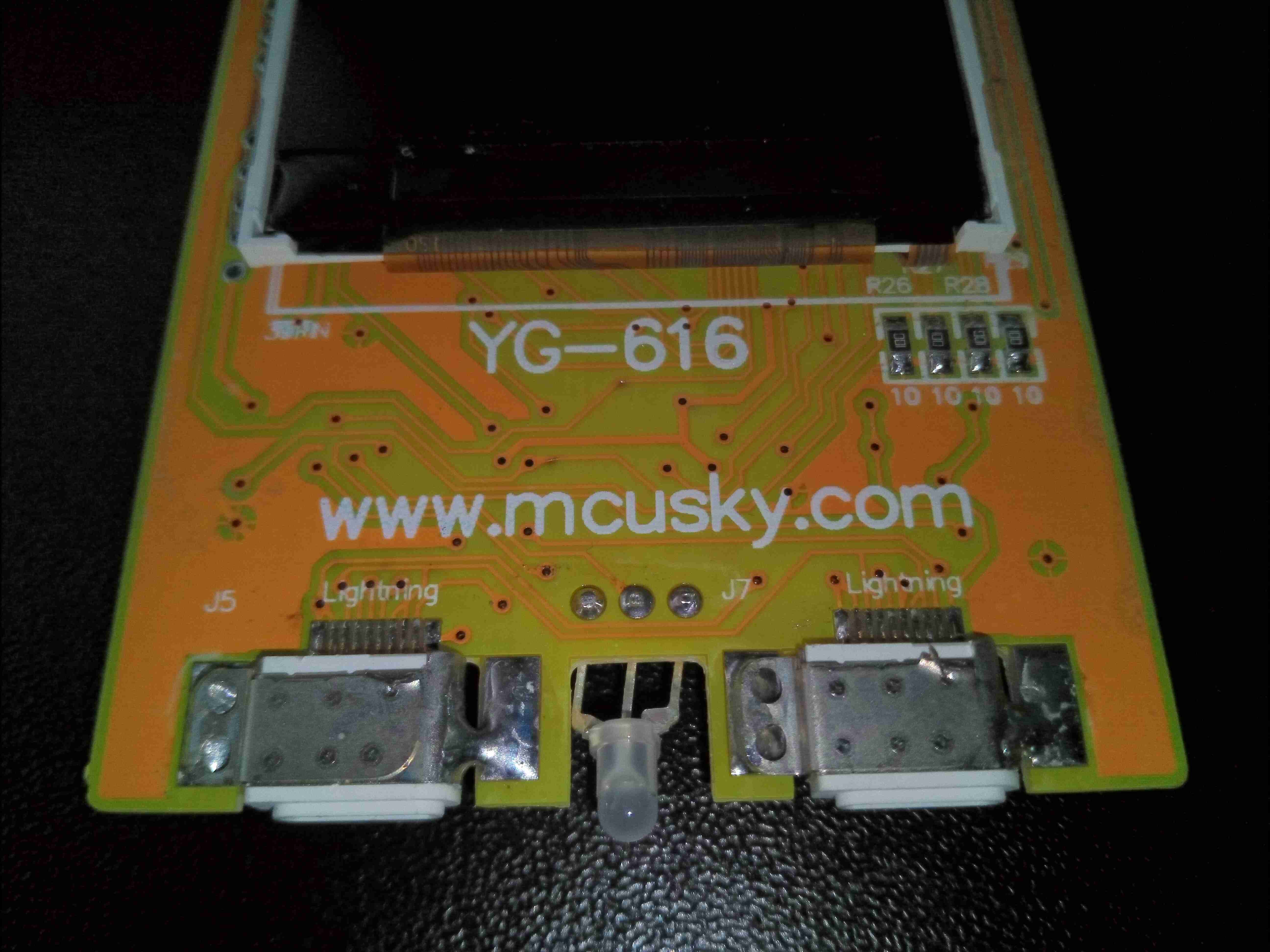
Apple’s Lightning cables are one of a new breed of cable – these have active electronics in the connectors, to allow the device to identify the type of cable being used. This is a little unit that reads out all the internal parameters of the ID chip inside the connector. As can be seen from the image above, the ID chip contains quite a bit of information, from device manufacturer & serial number to chip type & date of manufacture. This unit also gives a “score” of whether the cable is a genuine Apple type, or a Chinese clone, with a scale of 0-100.
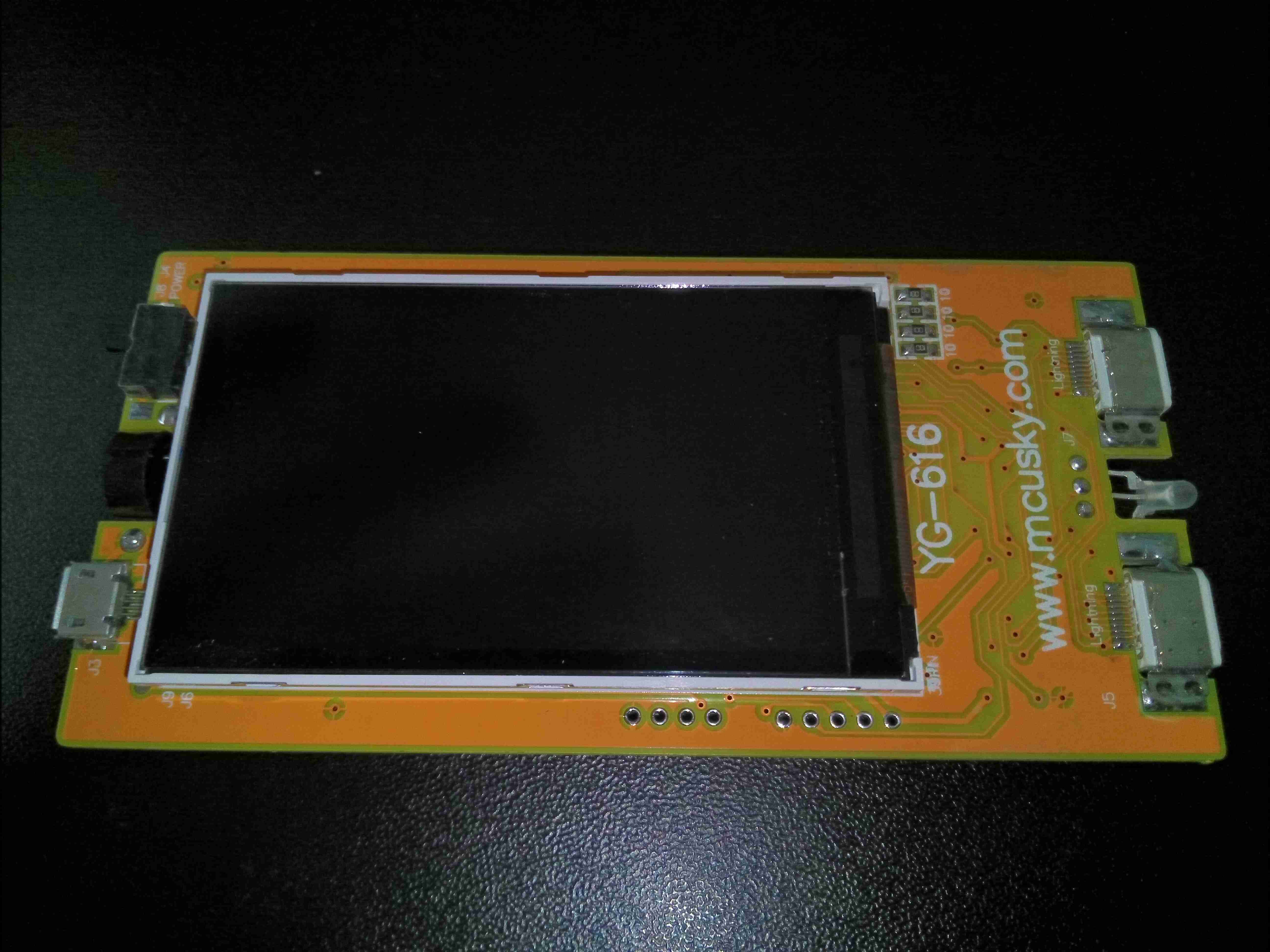
PCB Front
Pulling the PCB from the extruded aluminium case shows the large TFT LCD on the front of the board, with the µUSB charging port on the left side of the board, with the power switch & beeper. The right hand side of the board has a pair of Lightning connectors, which appear to be connected in parallel, and a status LED.
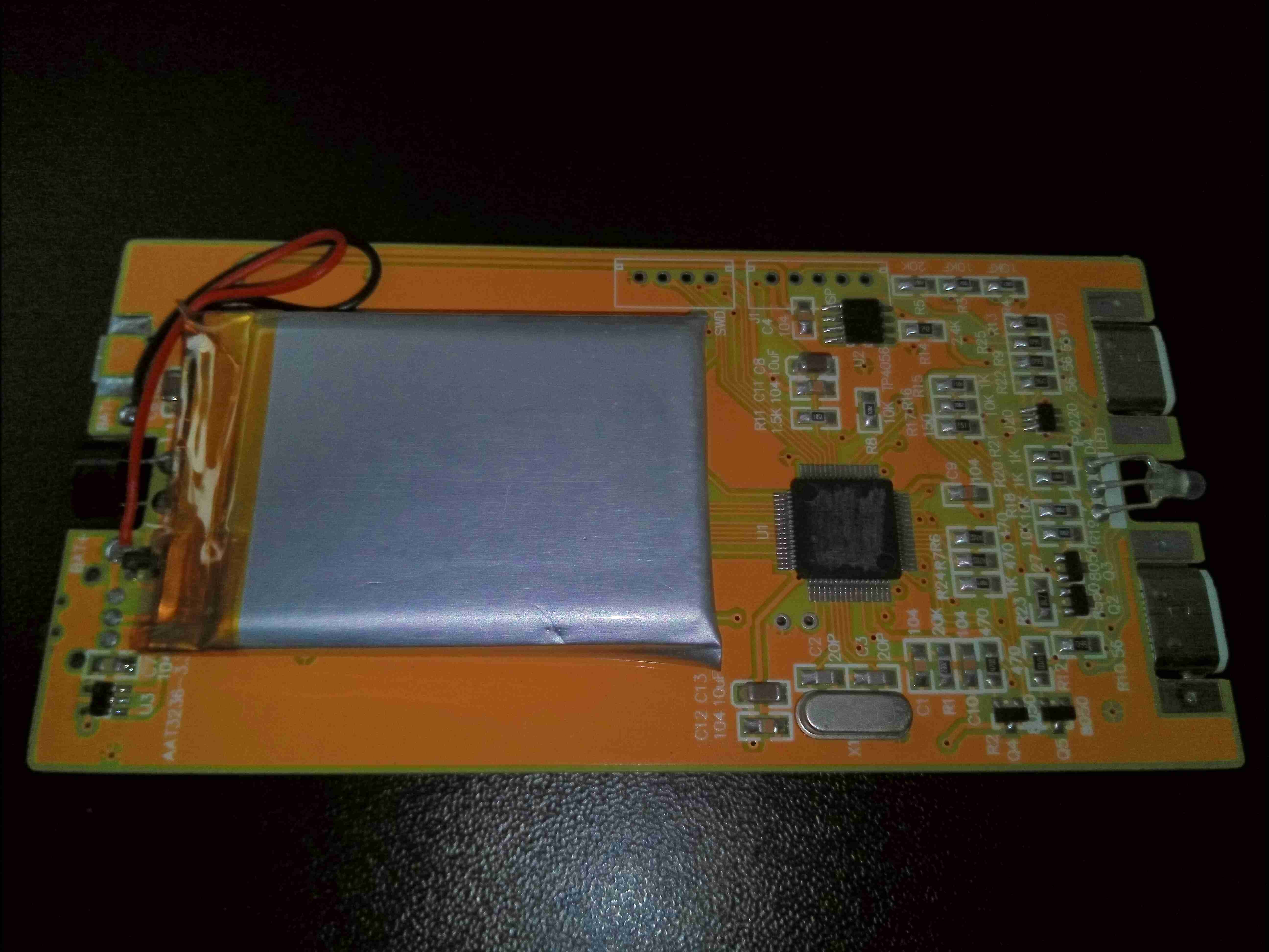
Internal PCB
The rear of the PCB has all the electronics, along with the small Li-Po cell used for power. Next to the battery on the left is a 3.3v linear regulator. The right side of the board has the main microcontroller and support electronics.
Connectors
Here’s a closeup of the connector end of the board, with the manufacturer’s web address clearly marked. Heading over to the website shows a company which produces all types of industrial electronics test equipment.
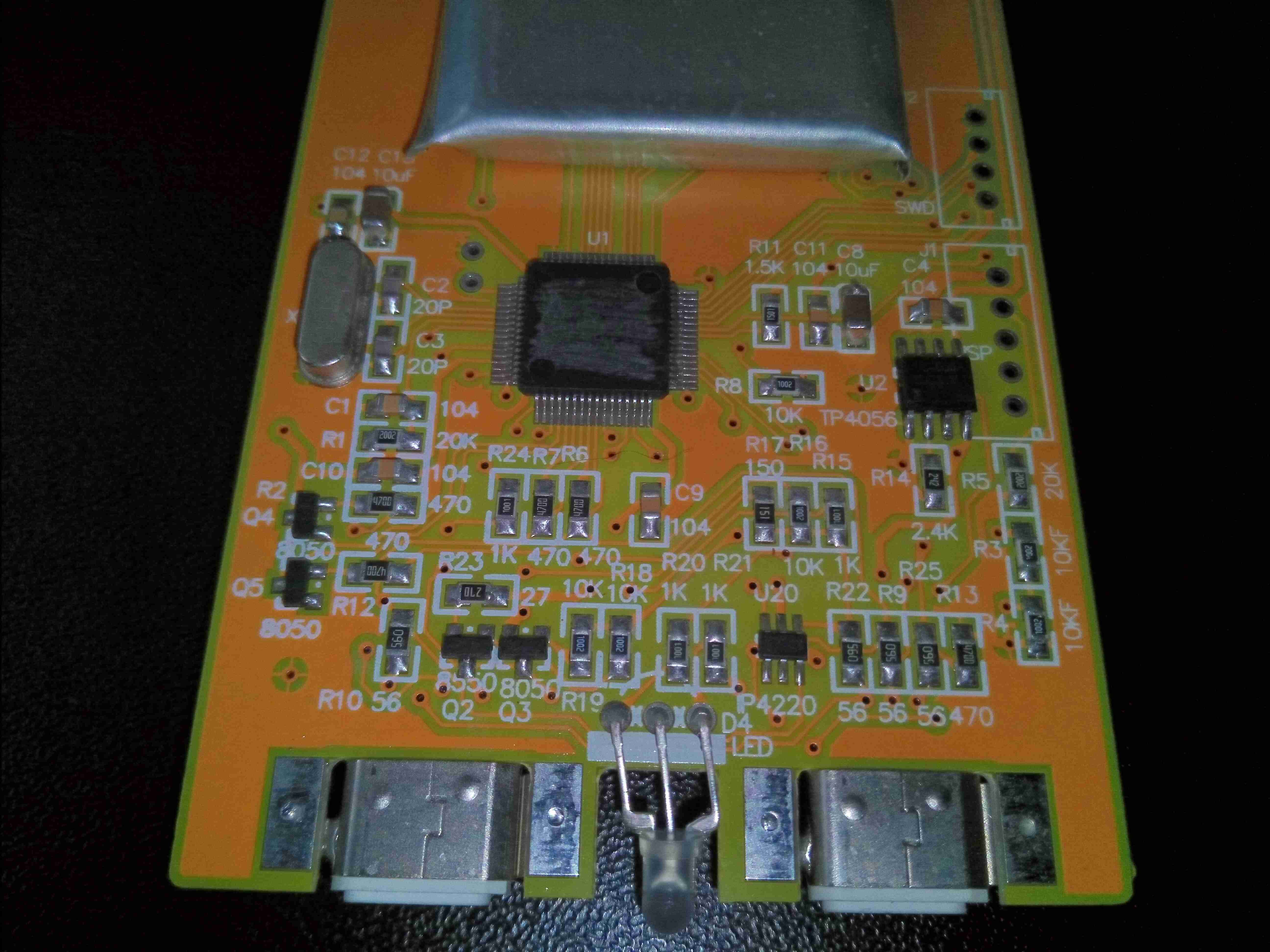
Main Chipset
Here’s where the magic happens. There’s a large microcontroller in the centre, which unfortunately has had the number scrubbed off, but it’s probably an STM32 variant, going off the ST-LINK SWD programming port. There’s a TP4056 lithium charger IC, and some discreet NPN transistors. The only other active component here is the IP4220 ESD Protection diode pack. Rather handily, all the component value identifiers are printed on the PCB silkscreen, apart from the microcontroller part number!
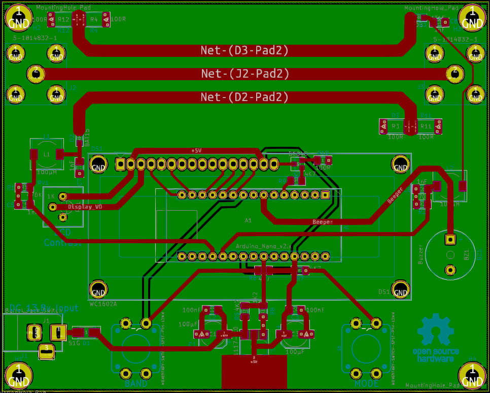
Since I wrote the post about the RF SWR & Power meter, I’ve been meaning to get around to a redesign of the board with a built-in directional coupler, and that time has finally come.
PCB Rev 2.1
So, here’s what I came up with. It’s pretty much the same as the first version on the acquisition & digital sections, but now there’s a built in directional coupler at the top edge of the board. Footprints are provided for N-Type connectors for the RF section. The effective length of the coupler is about 78mm, with 3mm wide tracks, with 2.8mm separation between the transmission line & the pickup lines.
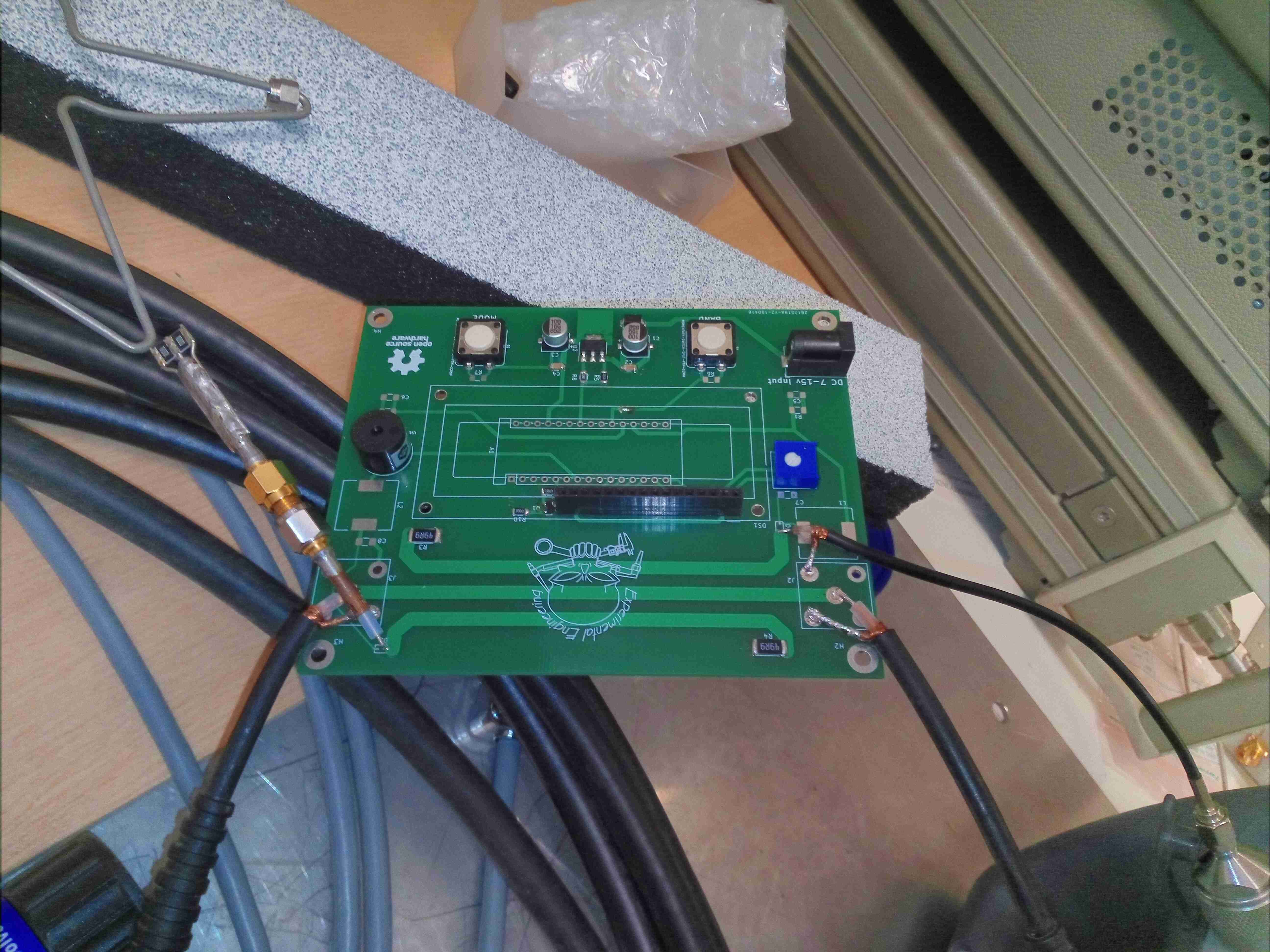
Network Analyser Setup
A quick turnaround from JLCPCB gave me some prototype PCBs to play with, and above I have a test board set up on a Network Analyser. I’ve got the unused parts terminated at 50Ω, and this gave me the following plots:
Forward Coupling
The response is pretty flat across the range at about -25dB coupling, rolling off at about 200MHz at the bottom end due to the relatively short length of the coupler. There’s a bit of a dip at ~700MHz, but I suspect that is down to one of the test cables used.
Reverse Coupling
The reverse power coupler gives a very similar result, with the 700MHz+ dip going in reverse. I suspect things aren’t that perfect due to the coupler tracks not being quite symmetrical. Revision 2.2 of the board should give me some slightly better results.
Well, this came as a little surprise. This is the PSU from a Microchip PICMASTER Universal Development System from 1993, intended for the old UV-erasable devices. On being plugged in, the PSU ran for about 10 minutes before a small explosion occurred, accompanied by an indescribable acrid smell. The photo above shows one of the X2 capacitors, across the AC input line has violently exploded, blowing the fuse (literally!) from it’s clips, and showering the inside of the PSU with bits of foil & paper. There’s another two of these on the other side of the common-mode choke, which are also showing signs of failure, however the fuse link disconnection has saved the others from the same fate.
All of these capacitors would need to be replaced with modern versions, but the PSU should still function fine afterwards. If I actually do the repair on this ancient system, I’ll do a further post.
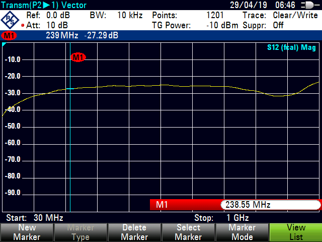
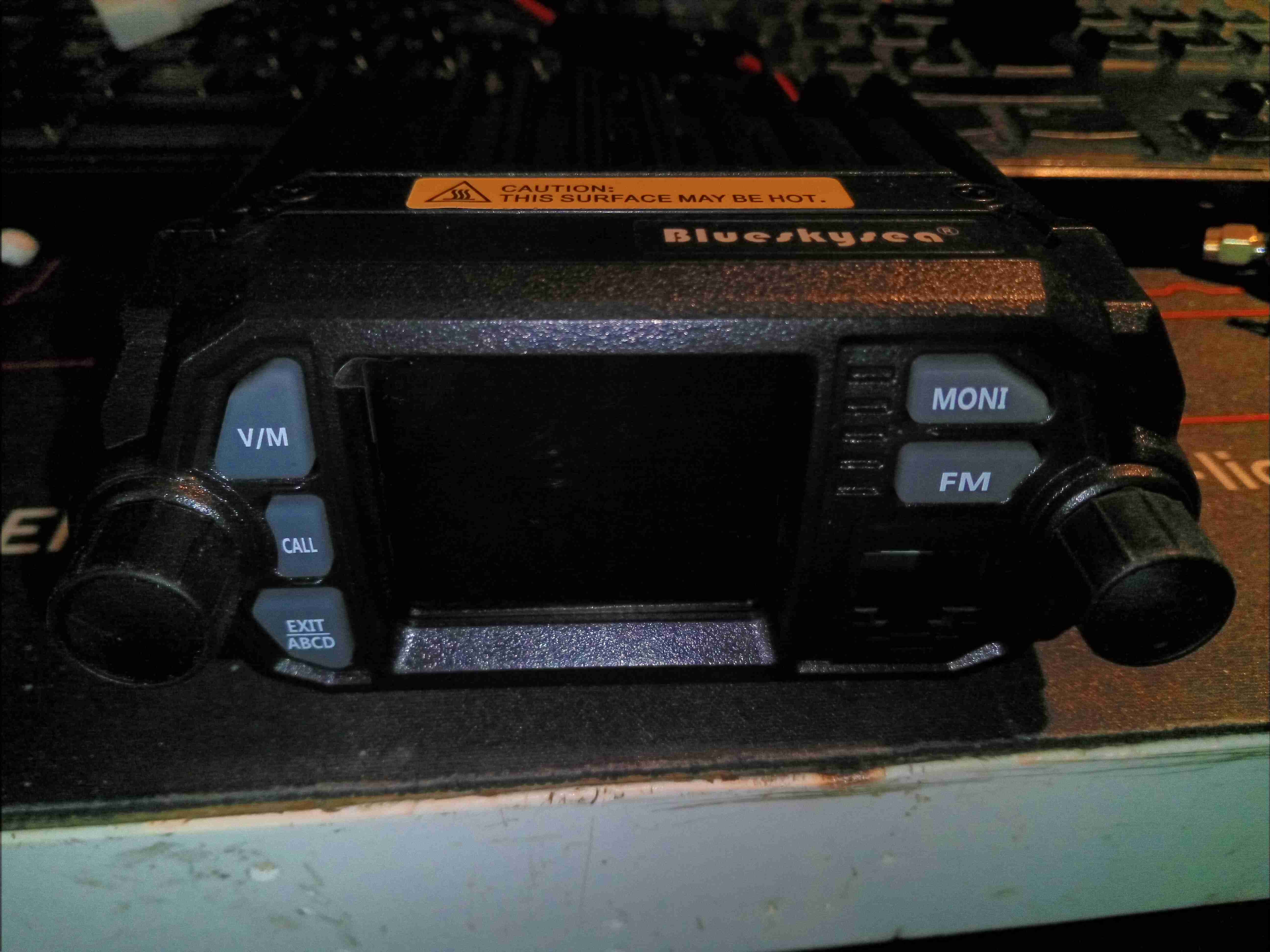
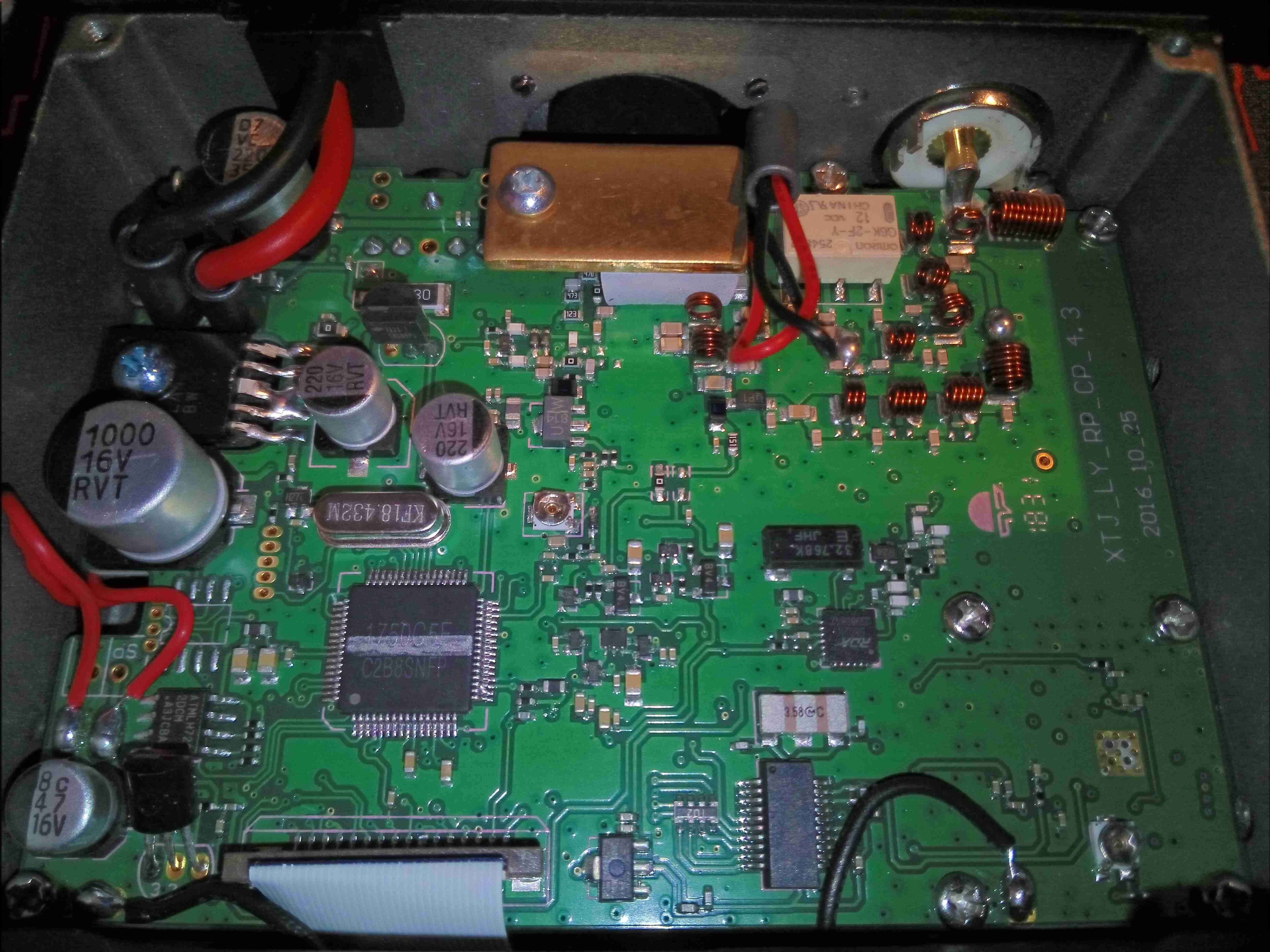
Here’s a miniature-sized mobile rig, which I purchased from eBay to fit in the car – my main Wouxun radio is far too big to fit under the dash! This unit is not much bigger than a UV-5R and cost less than £60! The front panel has a colour TFT LCD for the user interface, with a standard pot for volume, and rotary encoder for menu actions. Most of the controls are actually on the DTMF PTT mic, but some things are operable from the front panel.
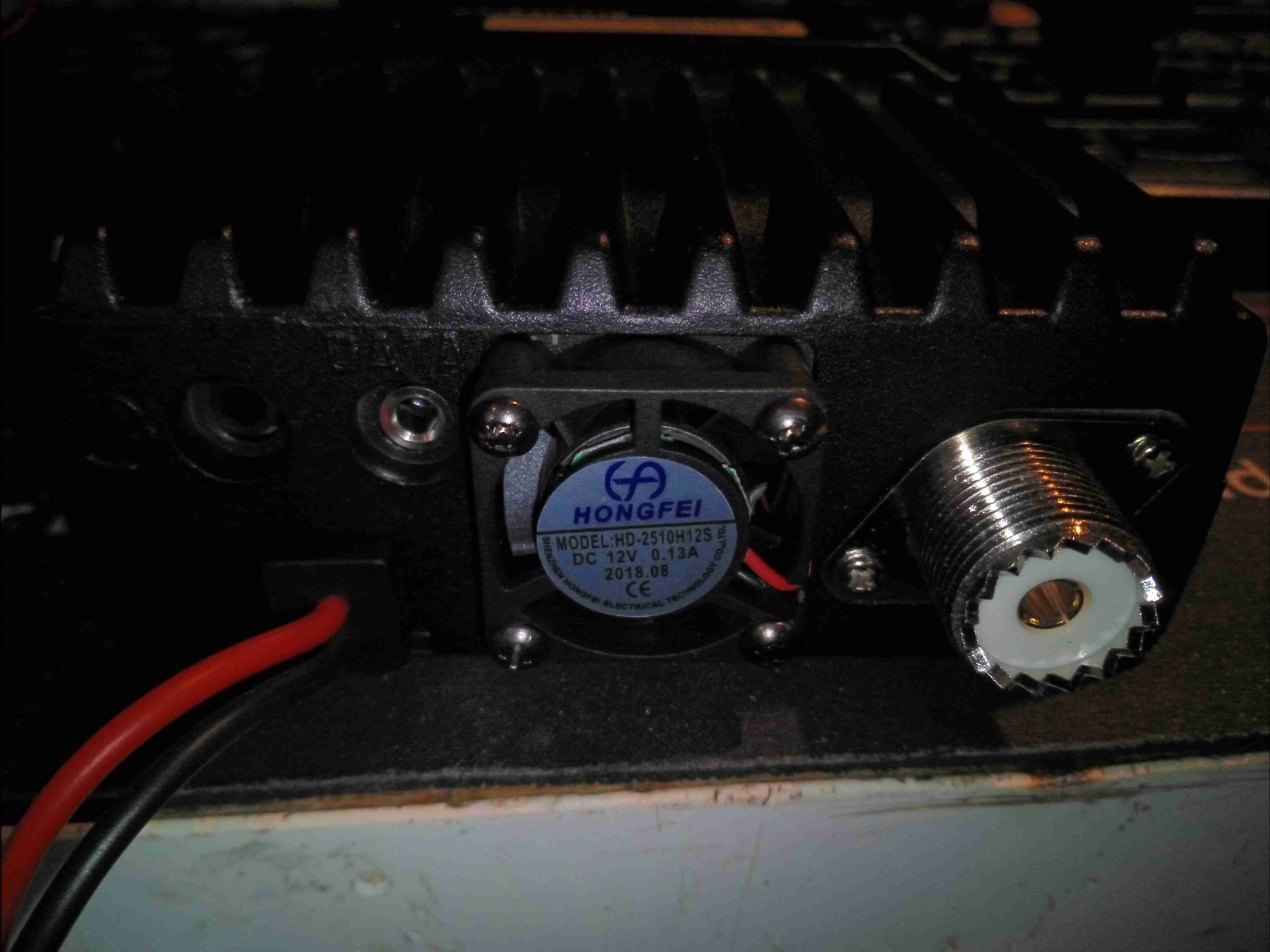
Rear Panel
The rear panel has a small fan to cool the internal RF power amp, and a PL-259 connector for the antenna connection. This will be the first thing to be replaced, with an N-Type. There’s also a headset connector on the back, along with a 3.5mm TRS jack for serial data – very important on this radio for programming, as the interface is abysmal in this department ;).
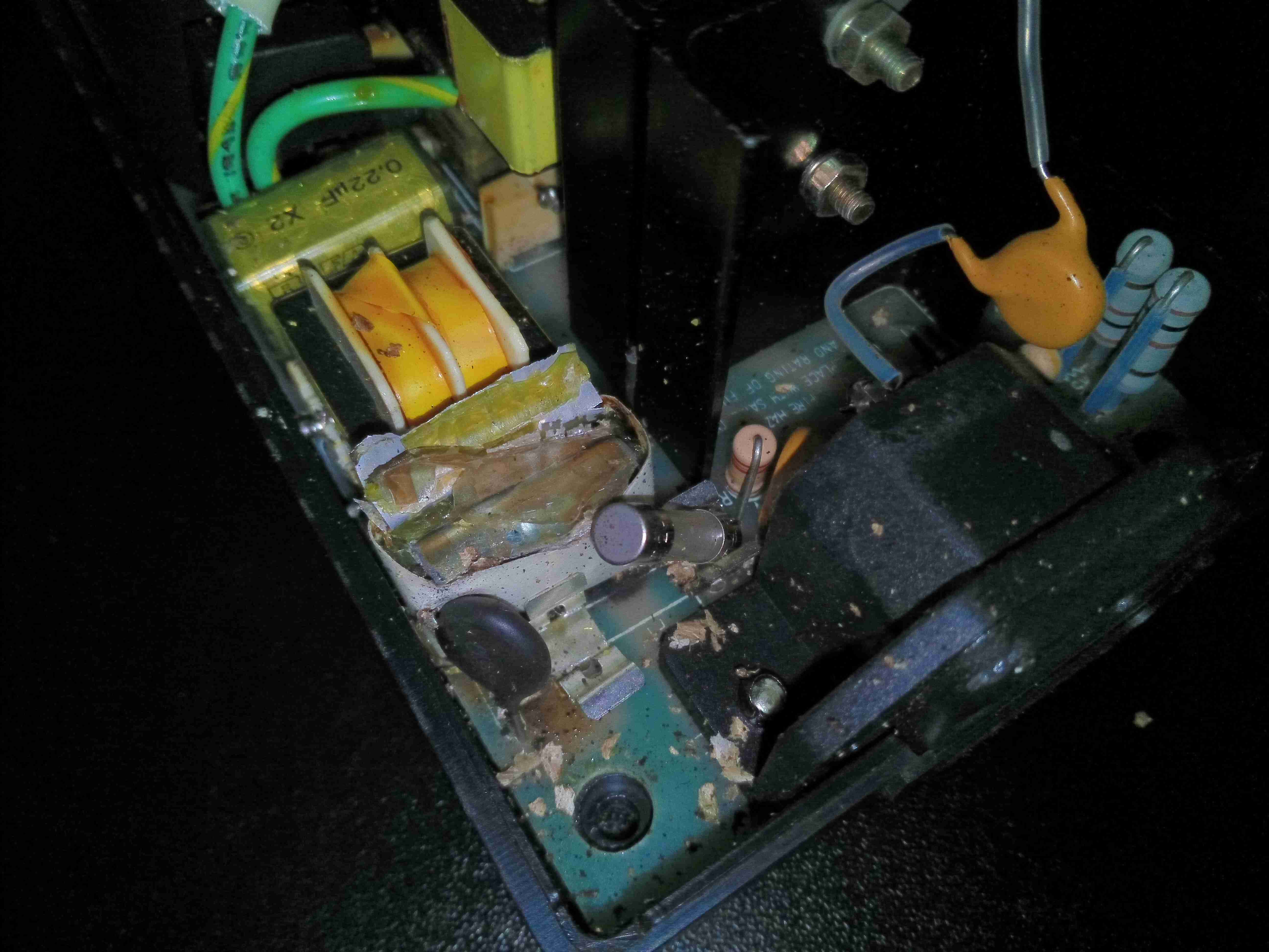
Internal View
Popping the plastic bottom cover off allows access to the internals. There’s a single PCB in here with a double-sided load. Unfortunately the PCB is too difficult to remove from the casing without damaging anything, so only this side to be seen! On the top though is the main system microcontroller, the broadcast FM receiver, voltage regulation and the RF output stages.
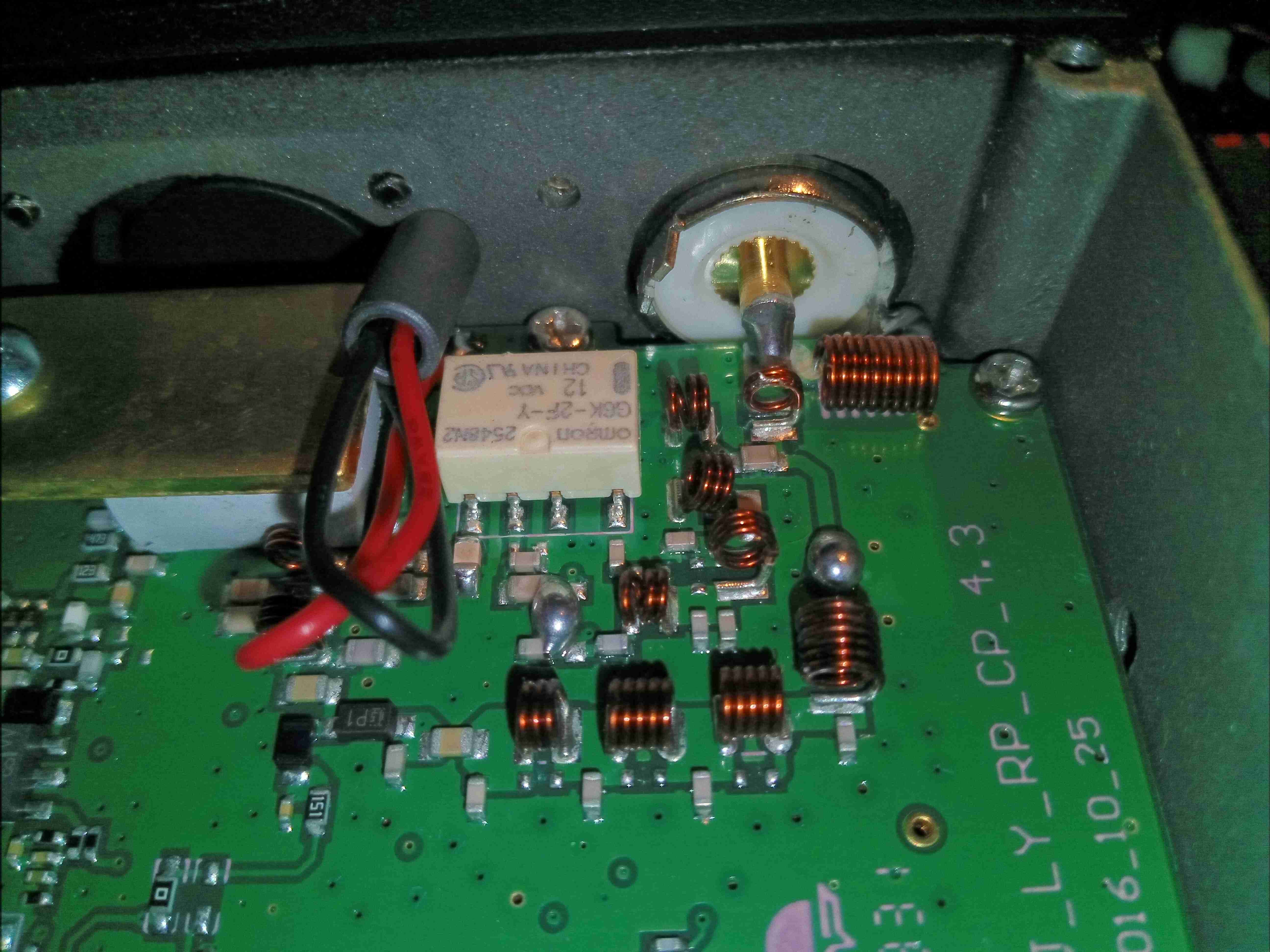
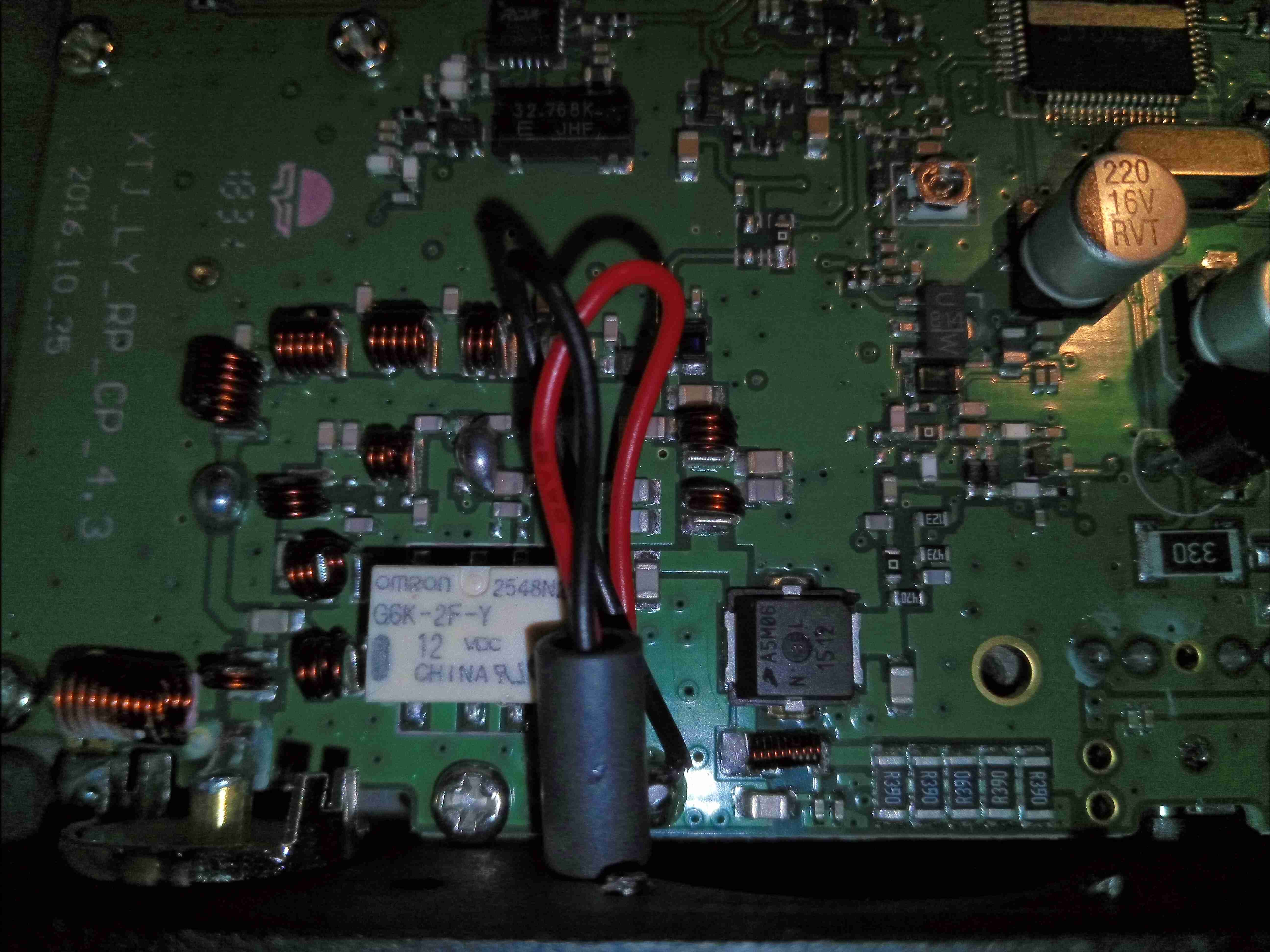
RF Output
The RF output filters are tucked into a corner of the board near the antenna connector, with a small relay to switch between VHF & UHF. My concern with this relay is that it’s not intended for RF use, and is in fact a general purpose relay. This would have been designed into the unit as a price reduction measure. Under the brass plate & thick SIL pad is the main RF output transistor. The external fan leads also pass very close to the RF output stage, so they may end up radiating some RF from the back of the unit, despite the ferrite bead on the leads.
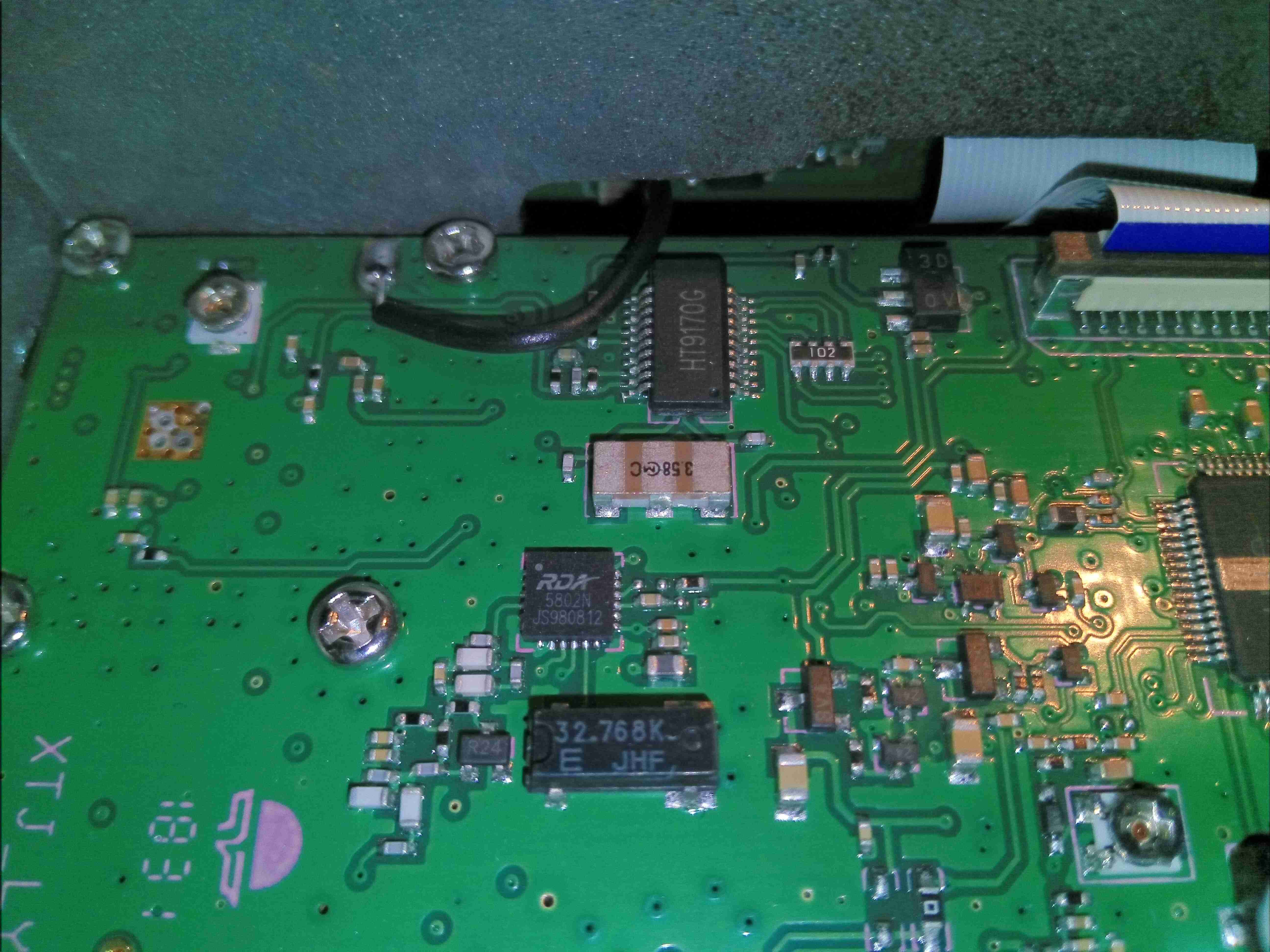
FM Receiver & DTMF Receiver
Just behind the front panel is the broadcast FM receiver, an RDA5802, with it’s 32.768kHz clock crystal. Just above that is the DTMF receiver & decoder, used in most Chinese radios, with it’s ceramic resonator. There’s a couple of unmarked pots on the board, but I am not certain what their function is.
RF Output Stage
Here’s the RF output stage, with the “heatsink” removed. I’m concerned on several fronts with this part – the heatsinking provided by a small brass plate and thick SIL pad is going to be poor at best, but looking at the datasheet for the main RF transistor, an AFT05MS006NT1 RF LDMOS N-Channel Lateral MOSFET from NXP shows some alarming numbers. Grab the full datasheet [download id=”7839″].
Remember that this radio is intended for mobile use in vehicles – the electrical systems of which can in a normal operational state rise to 14.8v.
This transistor is intended for handheld radio use, with an operational voltage of 7.5v, and absolute maximum ratings of 12.5v! Even when used on a regulated 13.8v PSU, the absolute maximum rating for the transistor is being exceeded.
At the very least, I would expect the life of the radio to be shortened due to this problem, and at worst the transistor may catastrophically fail in service, damaging the radio.
Main Microcontroller
The main microcontroller is a Renesas R8C series device, with quite a few peripherals. It is accompanied by it’s clock crystal, and a programming header. An FFC cable vanishes off to the front panel PCB for driving the LCD & connecting up the user controls & mic connector. Just to the right is the main voltage regulation section for the electronics, minus the RF output stage, which is directly connected to the DC input bus.
Front Panel PCB
There’s not much on the front panel PCB, so I won’t bother taking it out of the frame, this is going to mainly be interconnects for the SPI/I²C driven LCD & analogue channels for the audio.
I’ll keep the blog posted with lifespan checks on this radio, as I’m definitely concerned about the power amplifier transistor, but other than that it seems to be an OK radio. The rotary encoder has zero debounce, so it doesn’t work properly, but this isn’t much of an issue when the radio is fully operable from the PTT mic.
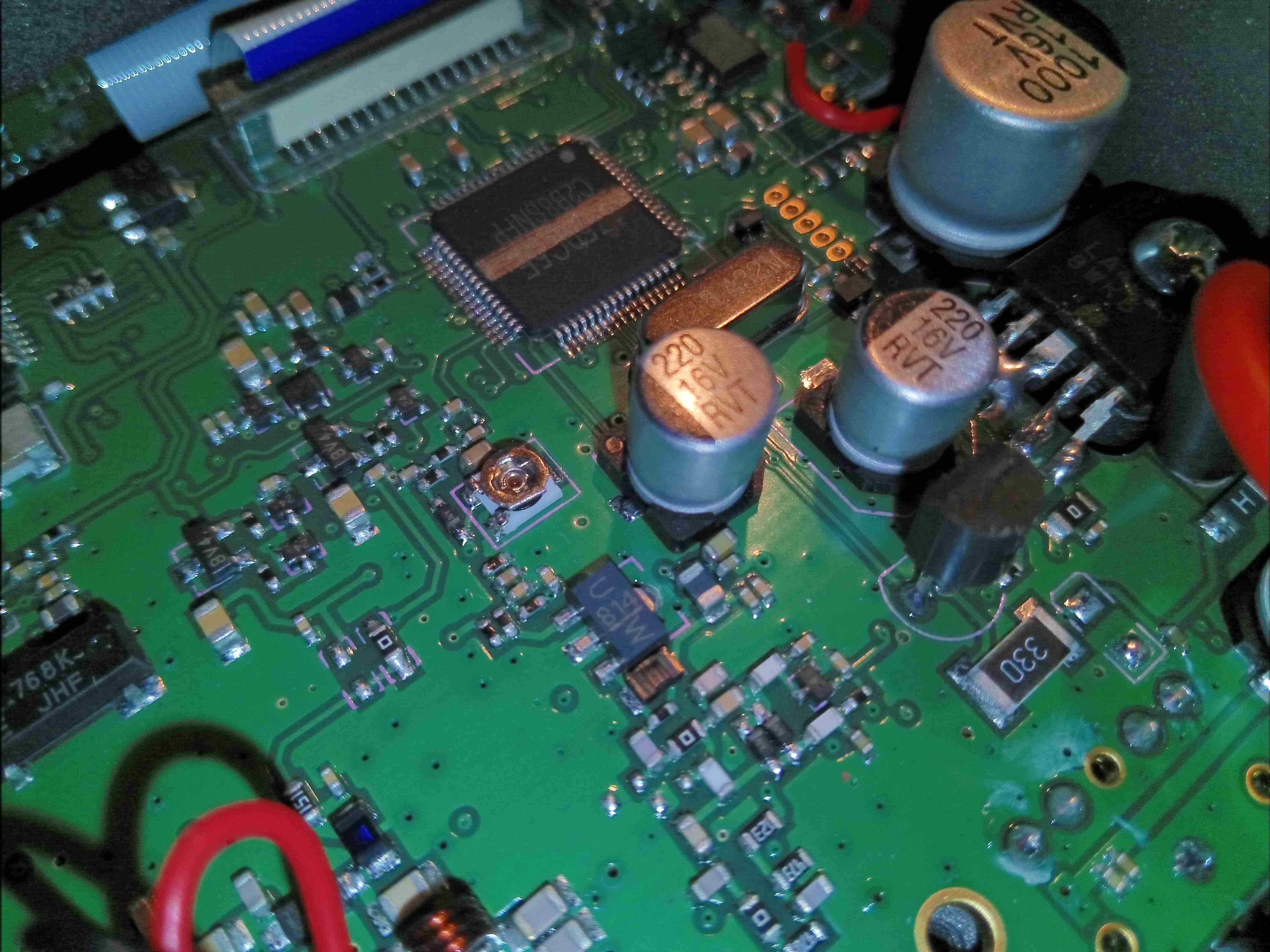
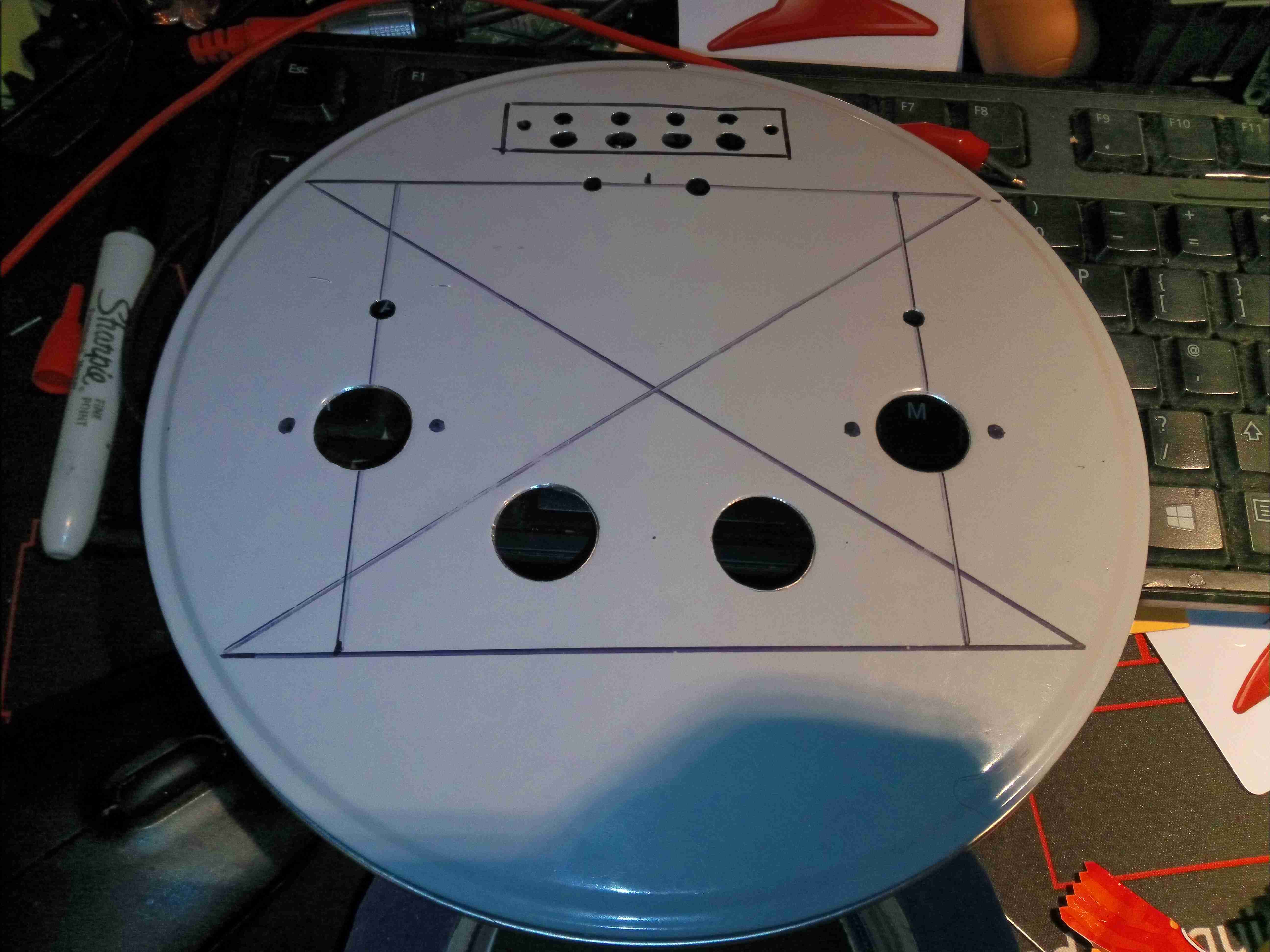
I figured it was about time I built another valve amplifier, and since I already had most of the required parts in stock, here it is! Above is the lid of a cake tin sourced from a local shop as a case, marked out & drilled for the valve sockets, output transformers & speaker terminals.
The ECL82 valve is a Triode & Audio Output Pentode in a single envelope, requiring only a single valve per audio channel. There are a pair of extra holes drilled here for a couple of EM80 magic-eye valves wired as VU meters to give a bit of a lightshow.
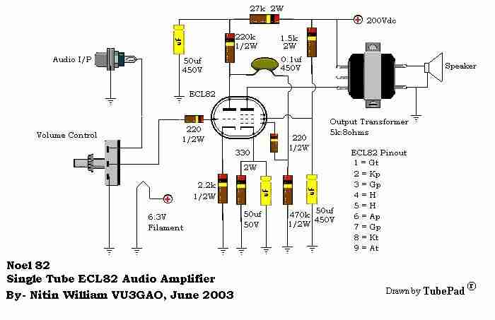
Amplifier Schematic
Here’s the base schematic for the Class-A ECL82 amplifier sections, obtained from the interweb. It’s pretty basic, and doesn’t mention a value for the volume potentiometer, so I used a 100K audio taper for that. Power will be supplied from low-voltage DC, running through a high voltage DC-DC converter for the anode supply of 200v, and a 5A buck converter for the 6.3v filament supply.
EM80 Schematic
The EM80 side is as the schematic above, the signal input being taken directly from the Pentode anode of the ECL82. I have removed the second 1N4148 diode down to ground, leaving only a single diode.
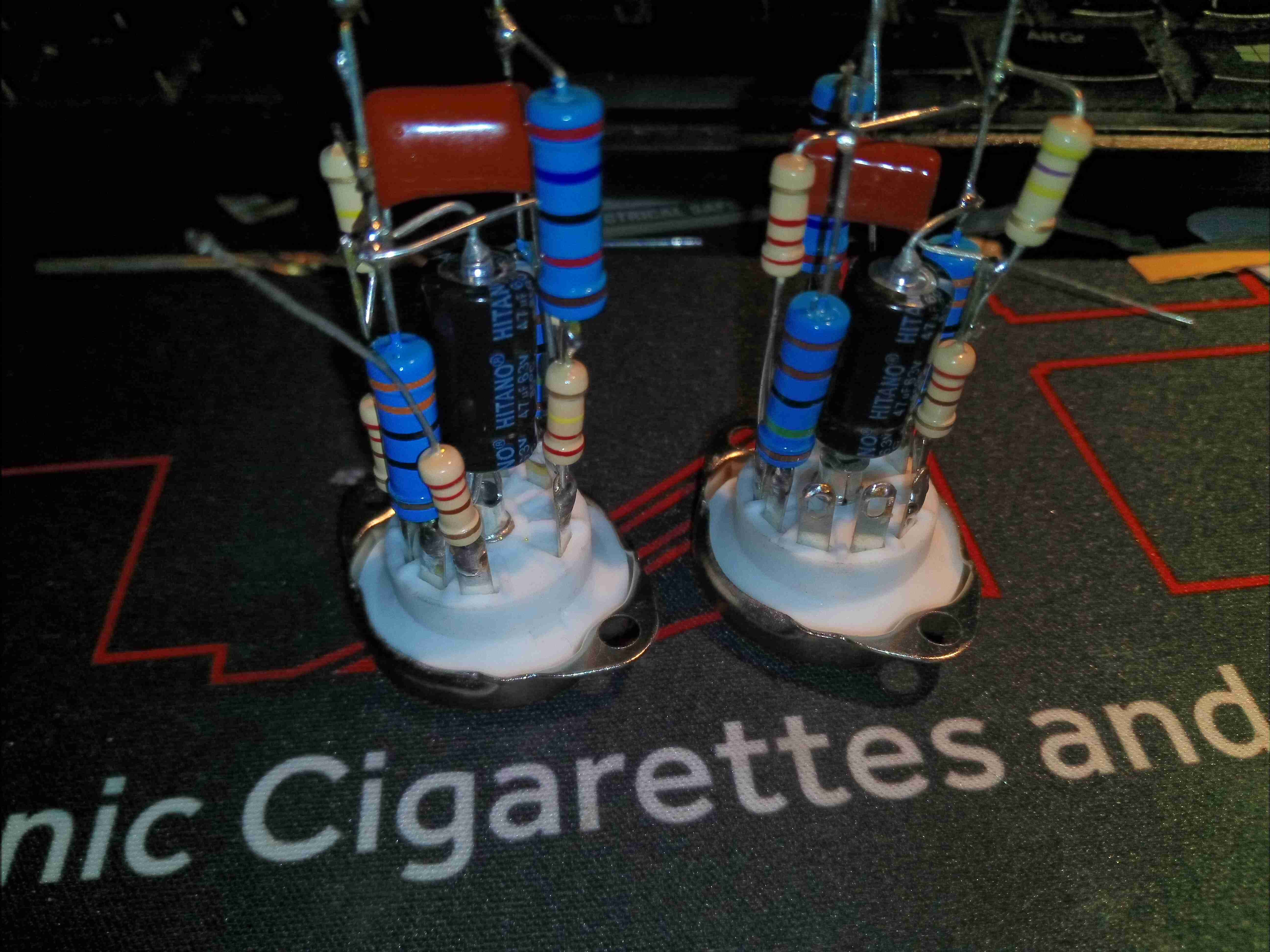
Valve Base
Most of the parts comprising the ECL82 amplifier stages are mounted directly on the back of the valve sockets, requiring only a 6.3v filament supply, 200v anode supply & audio I/O connections. Axial electrolytics have been used for ease of assembly, even though they’re getting a little expensive nowadays!
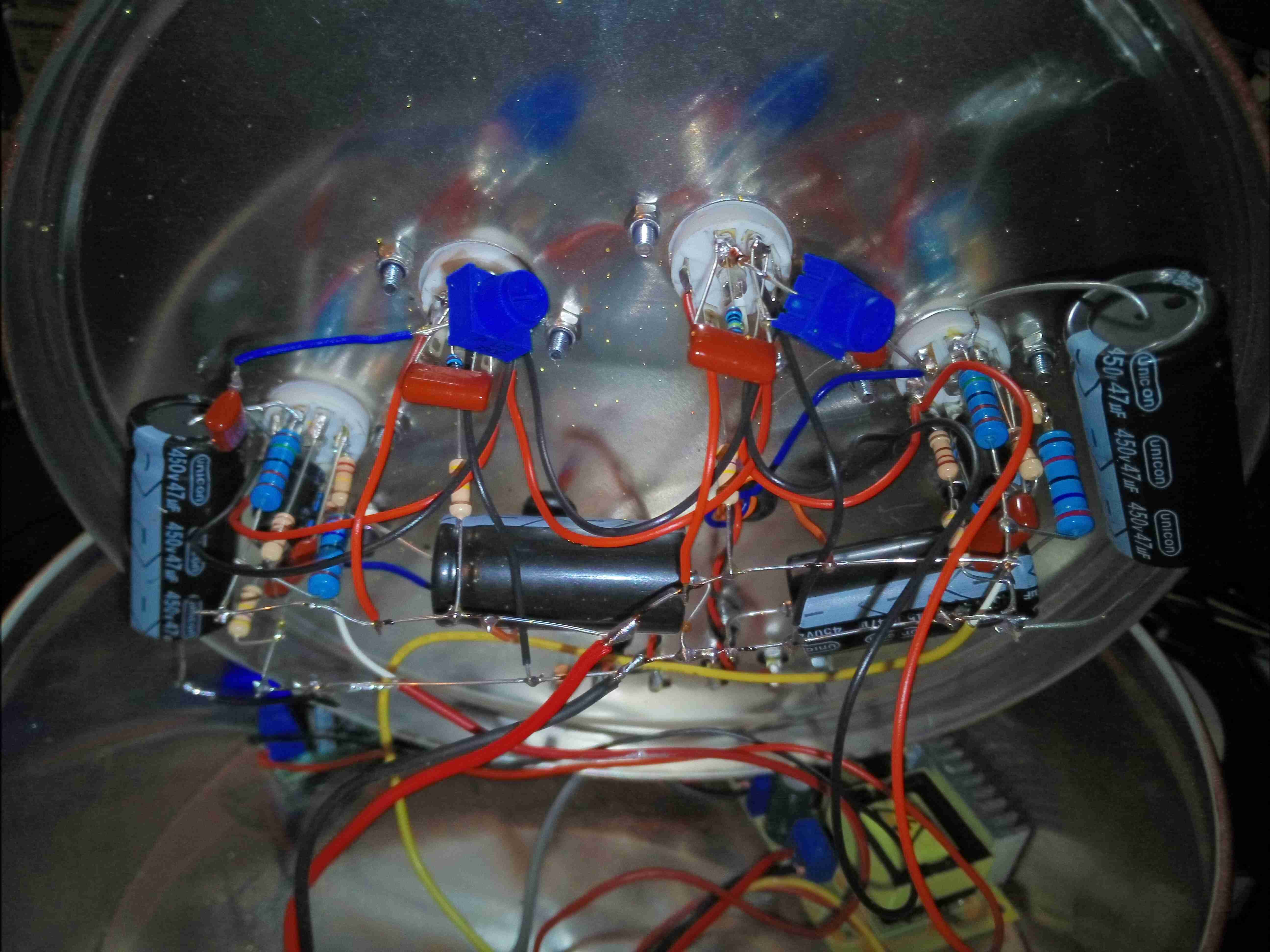
Point To Point Wiring
After fitting the components to the top lid, point-to-point wiring is used to connect up the valve socket assemblies. Some large electrolytics provide B+ smoothing, and all the filaments are daisy-chained in parallel. Audio is brought in on micro-coax from the I/O, and straight out to the output transformers on twisted pairs, keeping the audio wiring away from the B+ voltage.
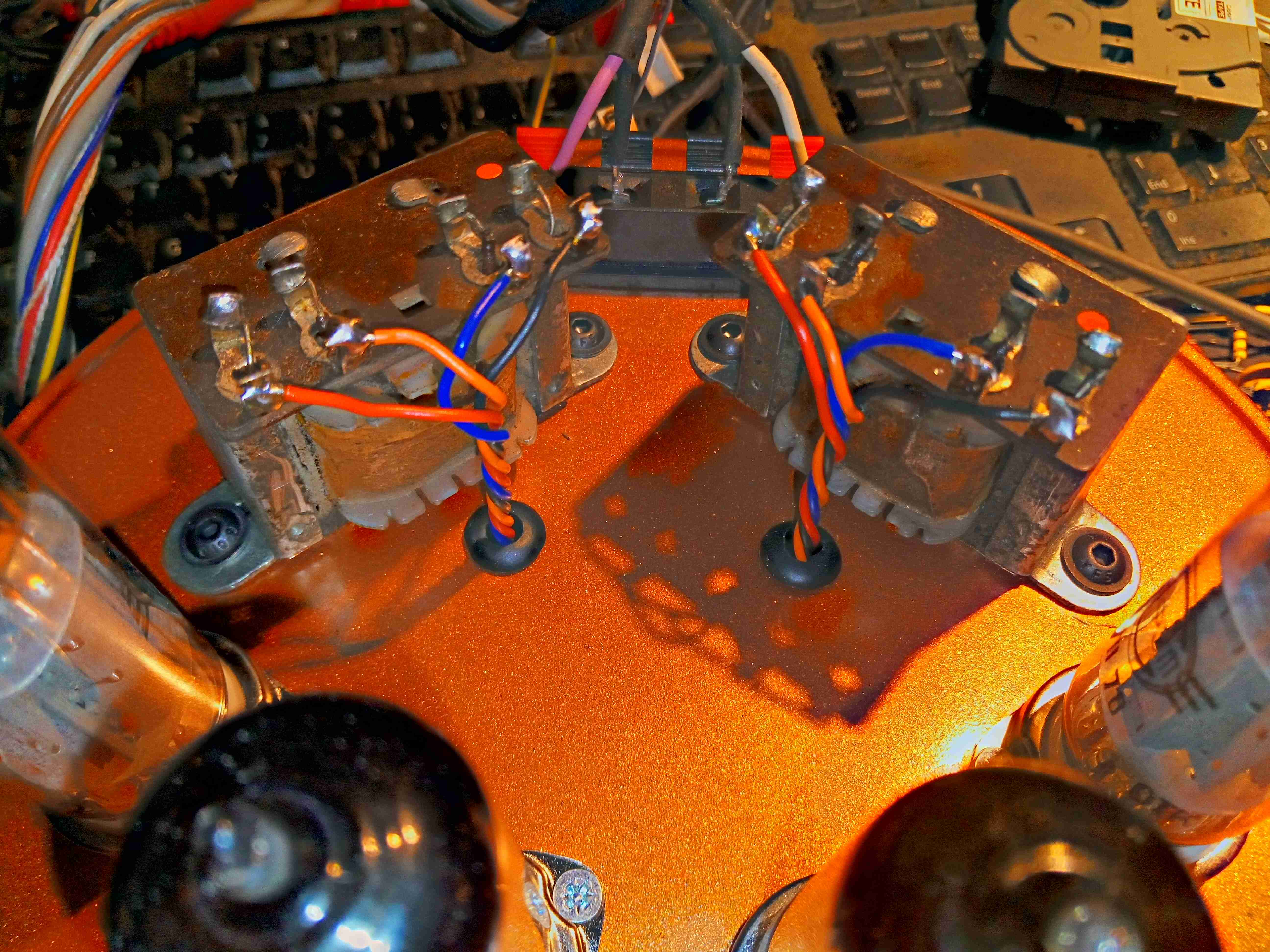
Output Transformers
The audio transformers, from a 1960’s Philips Radiogram, are mounted behind the valves, with the wiring emerging through holes in the case. I’ve already done the paint job here, in metallic copper.
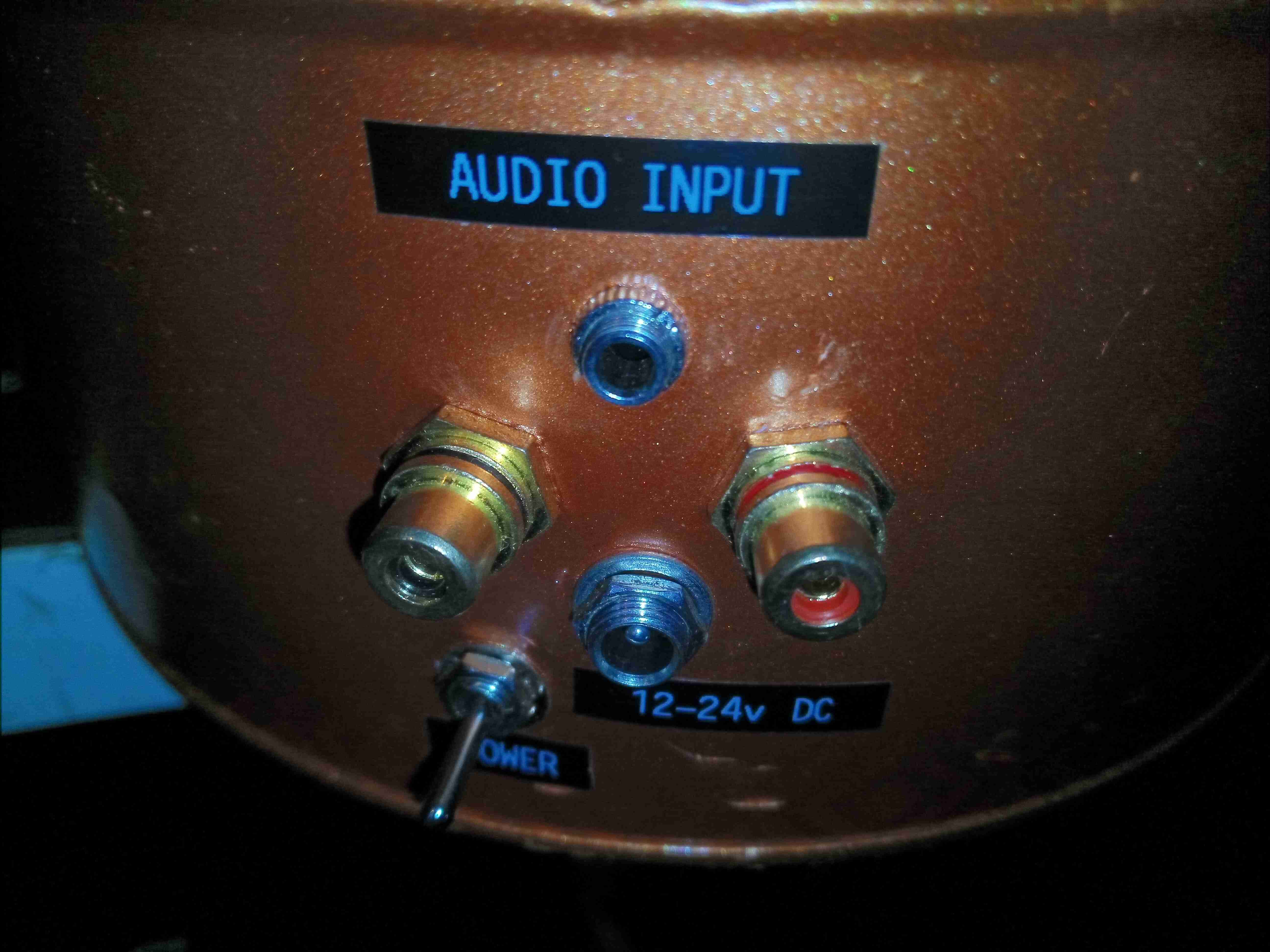
I/O
Audio & power sockets are on the back of the tin, with both 3.5mm Stereo inputs & phono inputs. A DC barrel jack takes care of the power, accepting 12-24v.
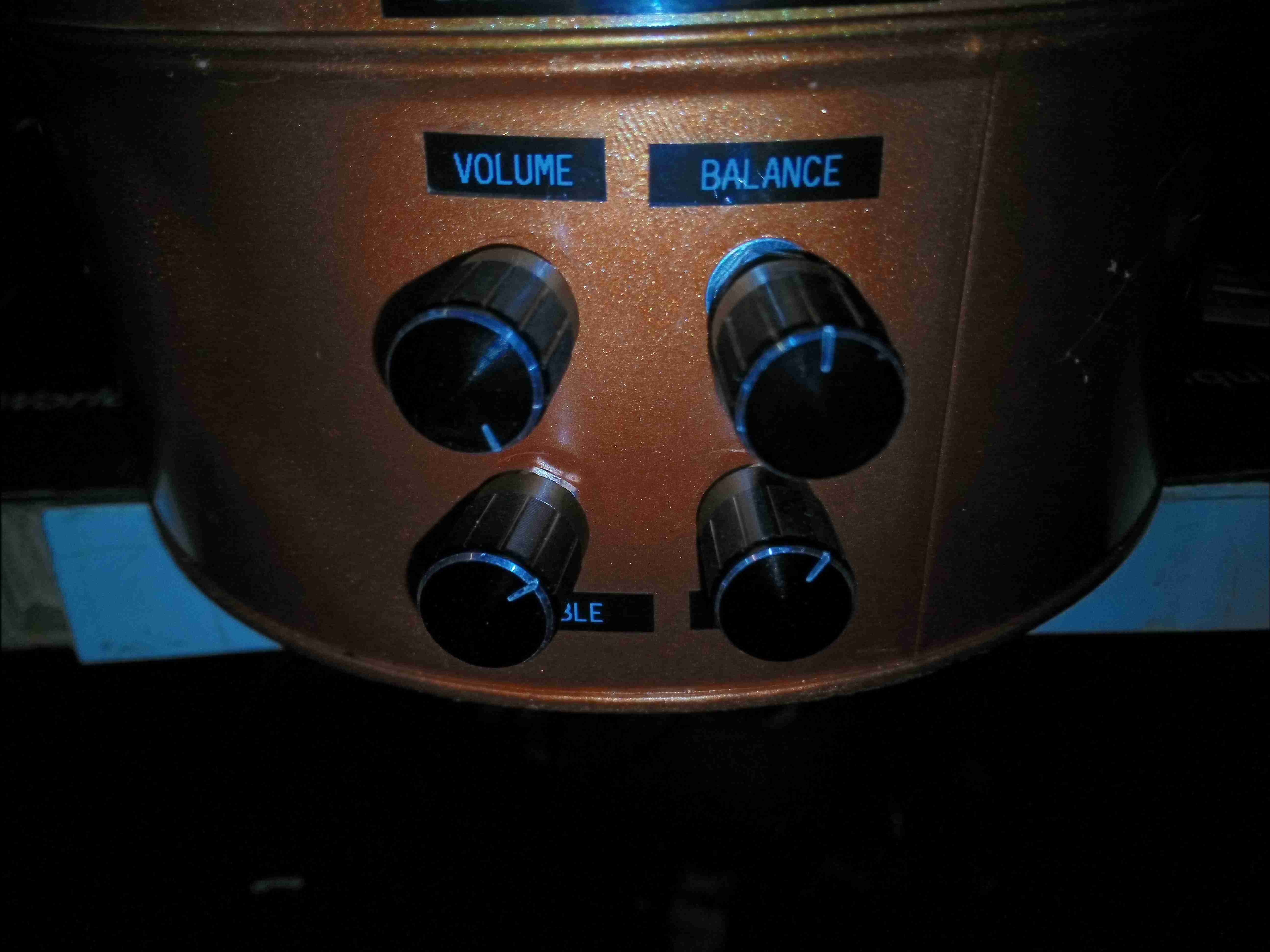
Controls
Controls on the front provide volume, balance, bass & treble adjustments.
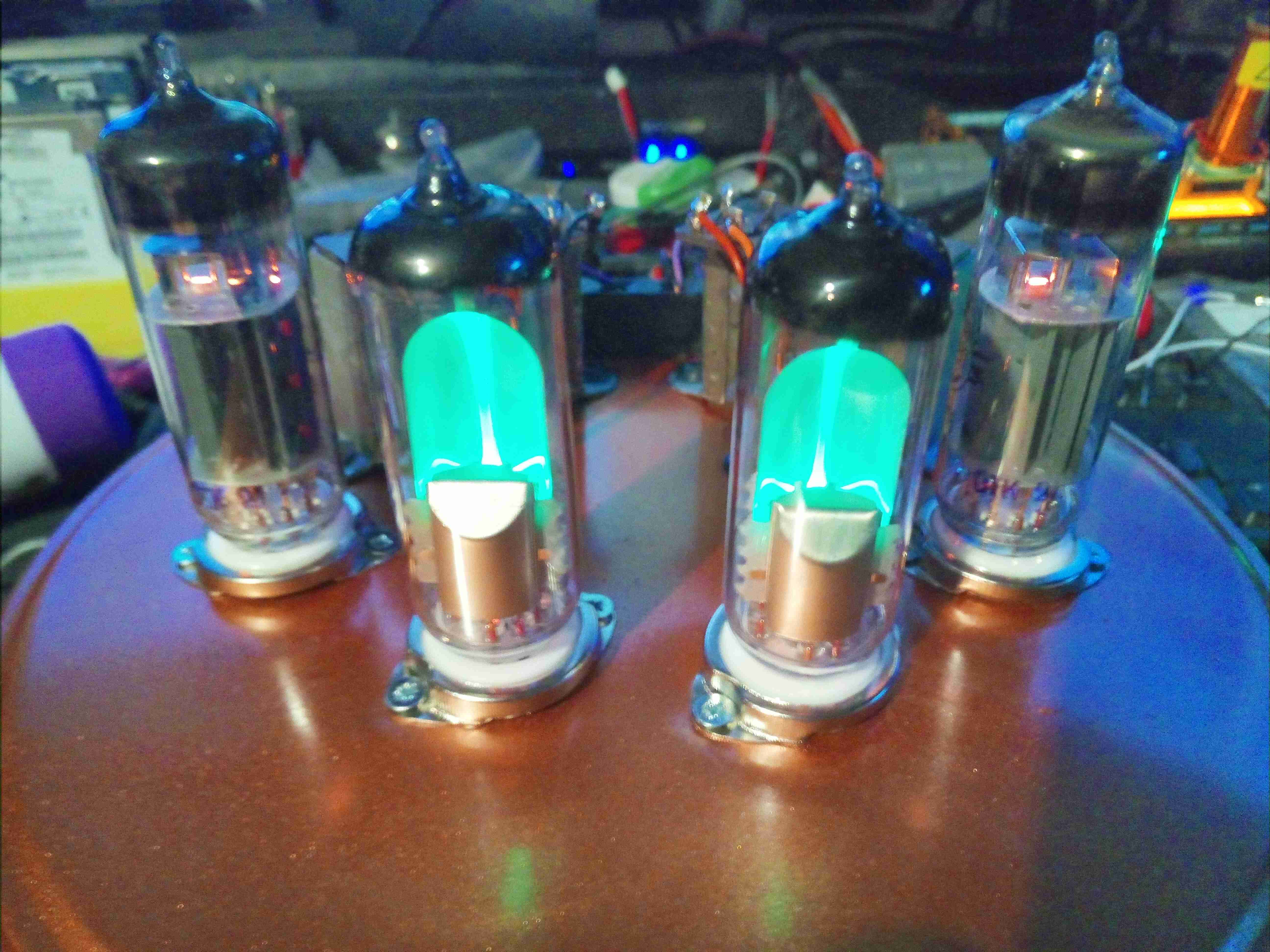
Amplifier Operational
Here’s the amplifier with it’s valves glowing nicely. Total power consumption is roughly 30W, using NOS Svetlana ECL82s & EM80s. In operation there is no hum or noise in the background, with no audio input the connected speakers are entirely silent.
Tip Jar
If you’ve found my content useful, please consider leaving a donation by clicking the Tip Jar below!
All collected funds go towards new content & the costs of keeping the server online.