Posted on 1 Comment

FE-5680A Rubidium Frequency Standard – Initial Teardown

Physics Package
Physics Package

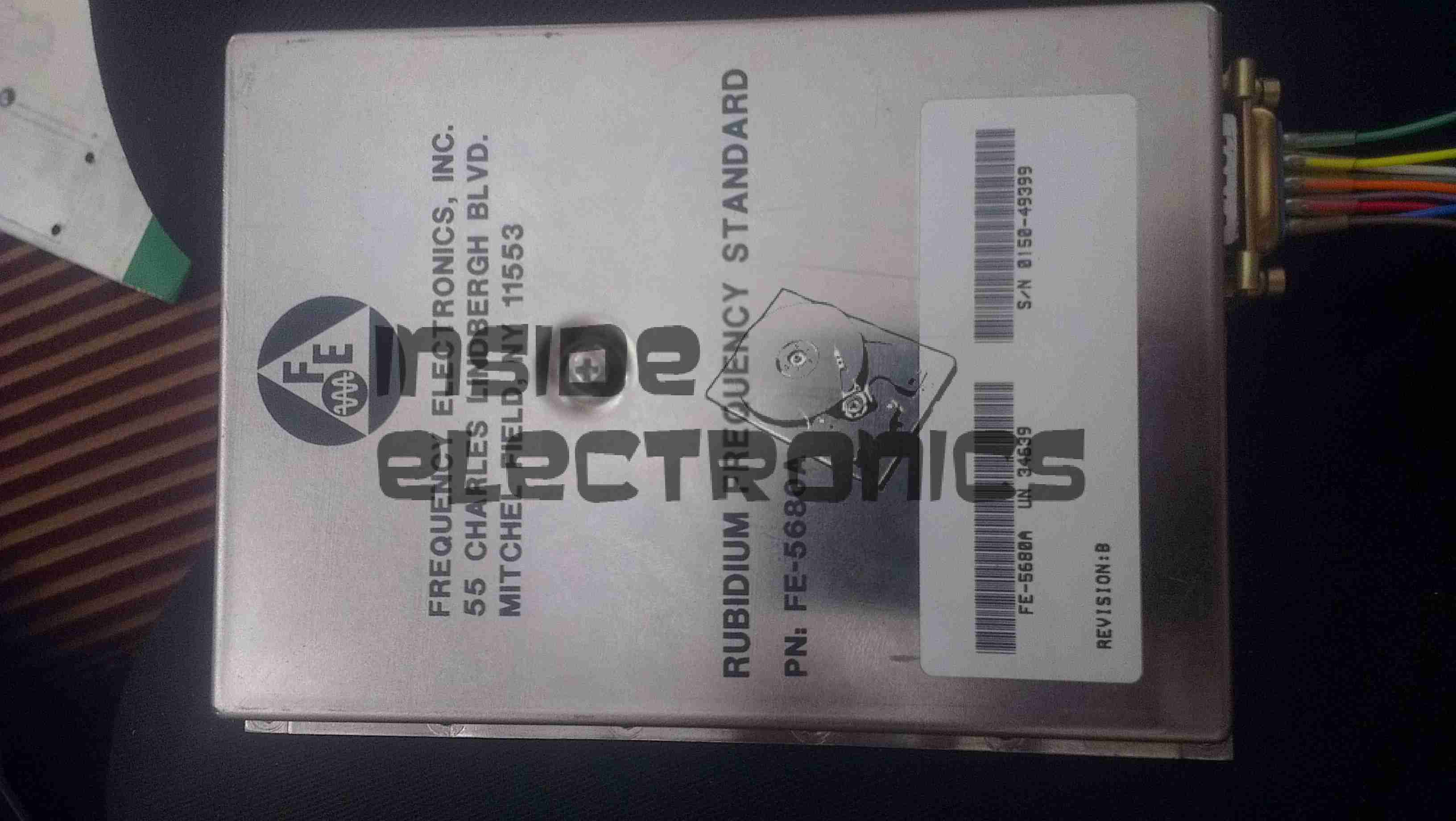
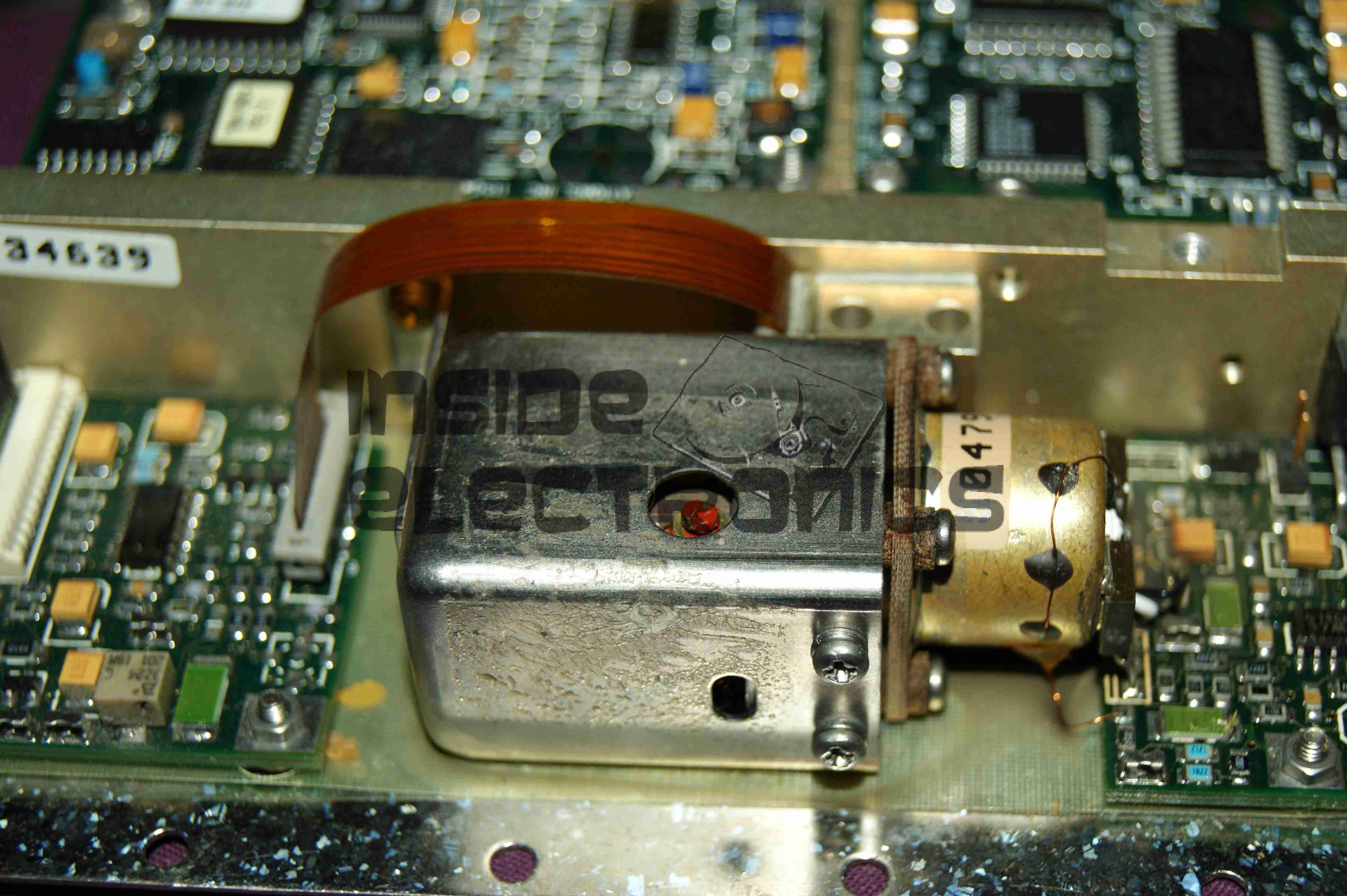
Here is a quick look inside the FE-5060A Rubidium Frequency Standard. Above you can see the entire physics package, with the rubidium lamp housing on the right hand side. The ribbon cable running into the resonator cavity has the power & signal traces for the internal heater, temperature sensor & Helmholtz coil.

Lamp End
Lamp End

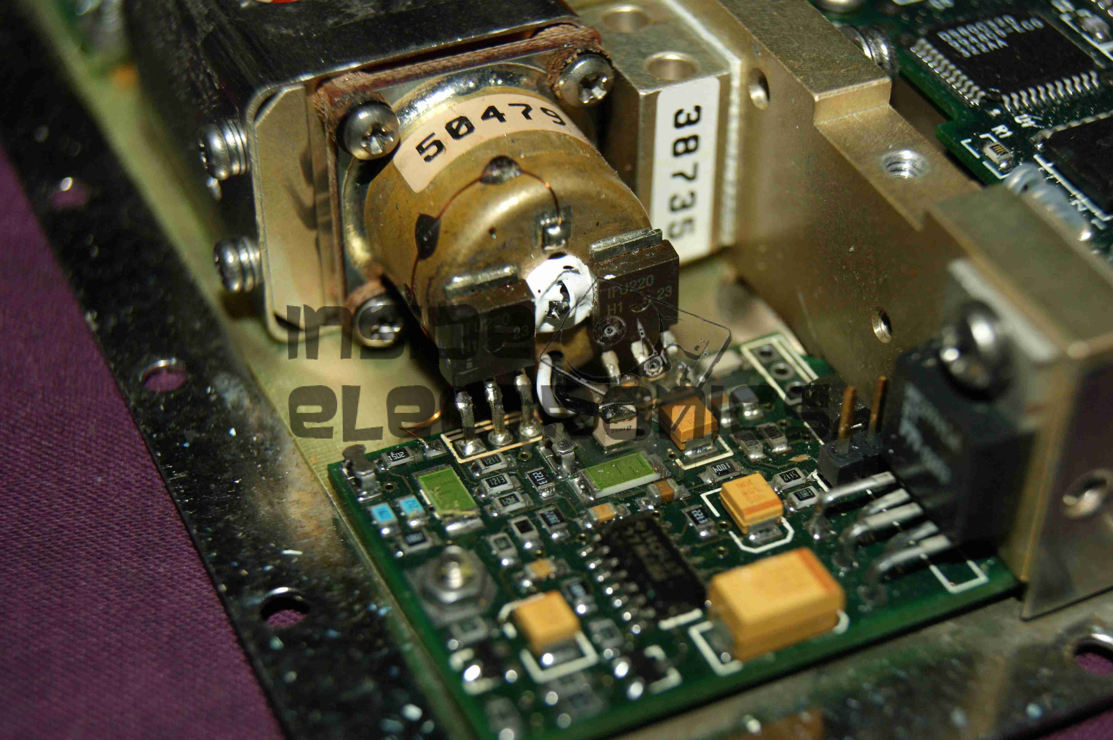
Here is the lamp end of the physics package, with the voltage regulator & RF driver for the lamp. The FETs soldered to the back of the housing are being used as heaters to maintain a constant temperature on the lamp in operation.
The temperature sensor can be seen between the two FETs, with a single copper wire running around the housing to connect to it.

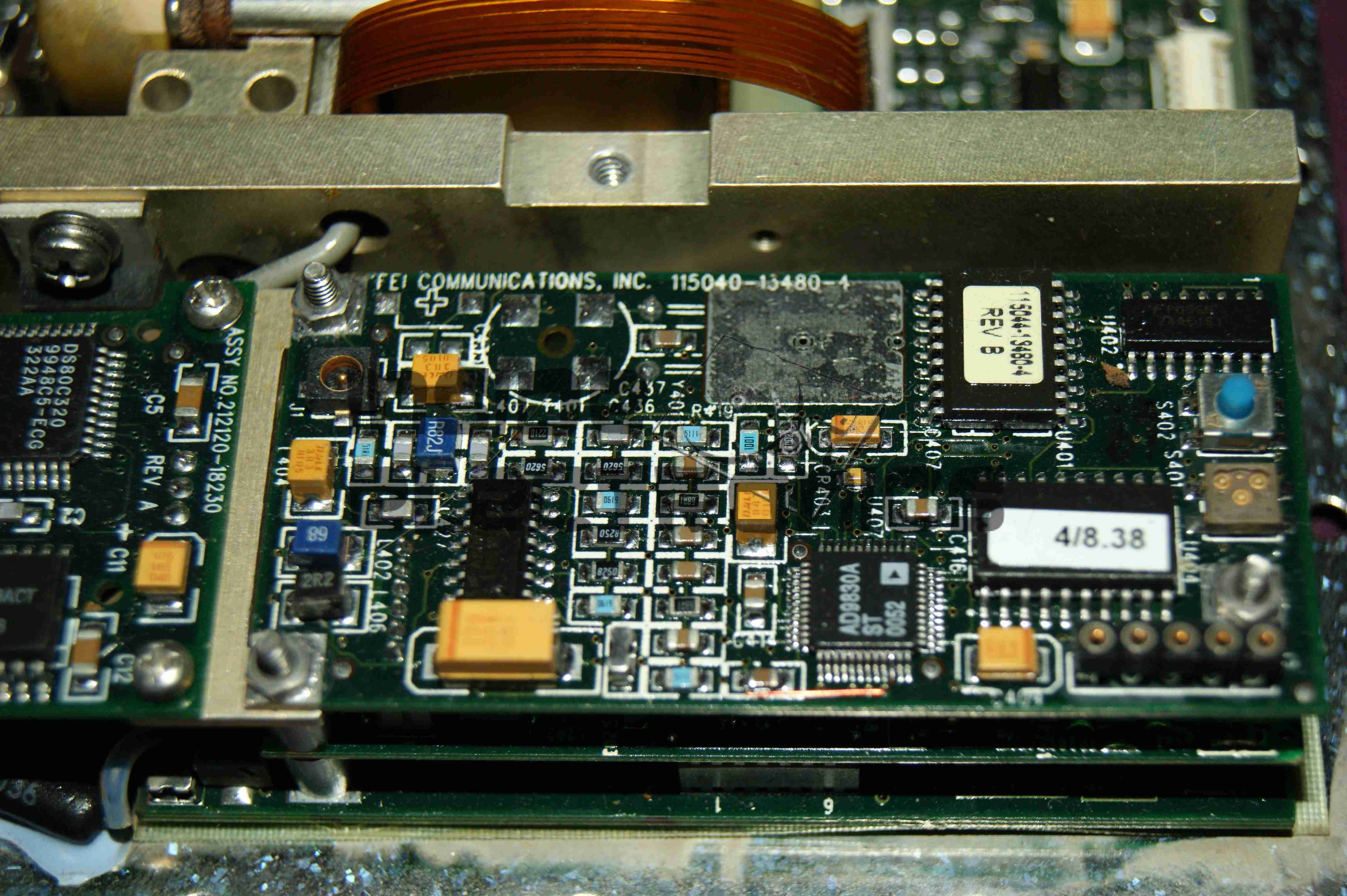
Main frequency synth board. This contains the RS-232 interface & the AD9830A from Analog Devices. This IC is a direct digital synthesizer & waveform generator.


Synthesizer Board
Synthesizer Board
Posted on Leave a comment

Wearable Raspberry Pi – Some Adjustments

USB Hub
USB Hub

As the first USB hub I was using was certainly not stable – it would not enumerate between boots & to get it working again would require waiting around 12 hours before applying power, it has been replaced. This is a cheapie eBay USB hub, of the type shown below.

These hubs are fantastic for hobbyists, as the connections for power & data are broken out on the internal PCB into a very convenient row of pads, perfect for integration into many projects.

Breakout Hub
Breakout Hub

I now have two internal spare USB ports, for the inbuilt keyboard/mouse receiver & the GPS receiver I plan to integrate into the build.

These hubs are also made in 7-port versions, however I am not sure if these have the same kind of breakout board internally. As they have the same cable layout, I would assume so.


Connector Panel
Connector Panel

Here is a closeup of the back of the connectors, showing a couple of additions.

I have added a pair of 470µF capacitors across the power rails, to further smooth out the ripple in the switching power supply, as I was having noise issues on the display.

Also, there is a new reset button added between the main interface connectors, which will be wired into the pair of pads that the Raspberry Pi has to reset the CPU.
This can be used as a power switch in the event the Pi is powered down when not in use & also to reset the unit if it becomes unresponsive.


Posted on Leave a comment

Wearable Raspberry Pi Part 2.5 – Battery Pack PCM

Battery PCM
Battery PCM

The final part for the battery pack has finally arrived, the PCM boards. These modules protect the cells by cutting off the power at overcharge, undercharge & overcurrent. Each cell is connected individually on the right, 12v power appears on the left connections. These modules also ensure that all the cells in the pack are balanced.


Posted on Leave a comment

Ultracapacitor Charge Balancing

Balancer
Balancer

I have finally  got round to designing the balancing circuitry for my ultracapacitor banks, which have a total voltage of 15v when fully charged. The 2600F capacitors have a max working voltage of 2.5v each, so to ensure reliable operation, balancing is required to make sure that each capacitor is charged fully.

The circuit above is a simple shunt regulator, which uses a 2.2v zener diode to regulate the voltage across the capacitor.

A 10W 1Ω resistor is connected to the BALLAST header, while the capacitor is connected across the INPUT. Once the voltage on the capacitor reaches 2.6v, the MOSFET begins to conduct, the 1Ω resistor limiting current to ~2.6A.

Each capacitor in the series string requires one of these connected across it.

PCB
PCB

Below is a link to the Eagle project archive for this. Includes schematic, board & gerber files.

[download id=”5555″]

Posted on Leave a comment

Wearable Raspberry Pi SMPS Modifications

SMPS Mods
SMPS Mods

A few modifications were required to the SMPS modules to make the power rails stable enough to run the Pi & it’s monitor. Without these the rails were so noisy that instability was being caused.

I have replaced the 100µF output capacitors & replaced them with 35v 4700µF caps. This provides a much lower output ripple.

There are also heatsinks attached to the converter ICs to help spread the heat.

Posted on Leave a comment

Wearable Raspberry Pi Part 2 – Power Supply

All Fitted
All Fitted

Progress is finally starting on the power supply unit for the Pi, fitted into the same case style as the Pi itself, this is an 8Ah Li-Poly battery pack with built in voltage regulation.

Regulator Boards
Regulator Boards

Here are the regulators, fixed to the top of the enclosure. These provide the 12v & 5v power rails for the Pi unit, at a max 3A per rail.

Battery Pack
Battery Pack

In the main body of the case the battery pack is fitted. This is made up of 4 3-cell Li-Poly RC battery packs, rated at 2Ah each. All wired in parallel this will provide a total of 8Ah at 12.6v when fully charged.

Powered Up
Powered Up

Here the regulators are powered up from a 13v supply for testing. I have discovered at full load these modules have very bad ripple, so I will be adding extra smoothing capacitors to the power rails to compensate for this.

I/O
I/O

Here are the connectors on the top of the unit, outputting the two power rails to the Pi & the DC barrel jack that will be used to charge the pack.