Posted on 9 Comments

Arduino Milliohm Meter Build

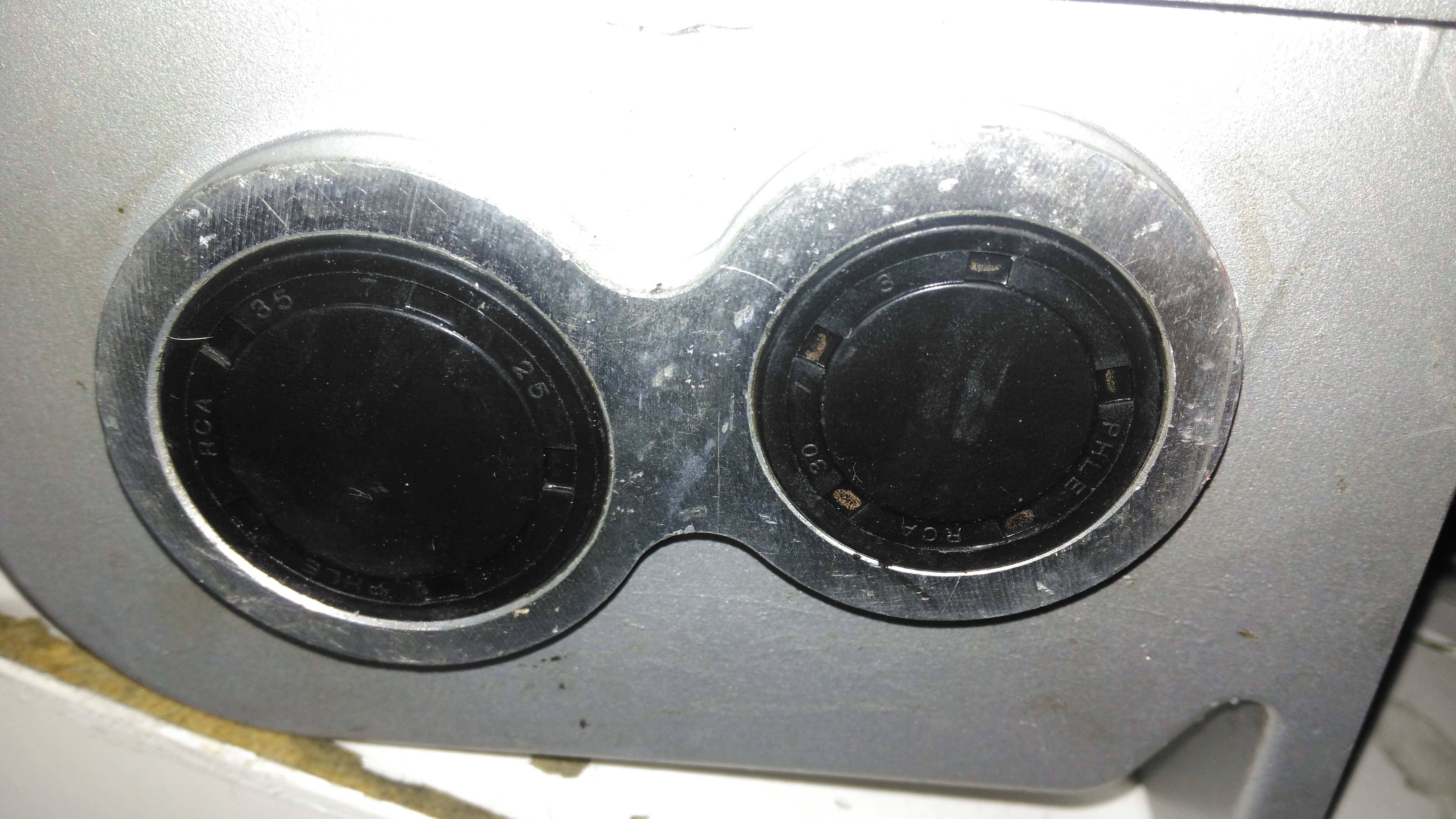
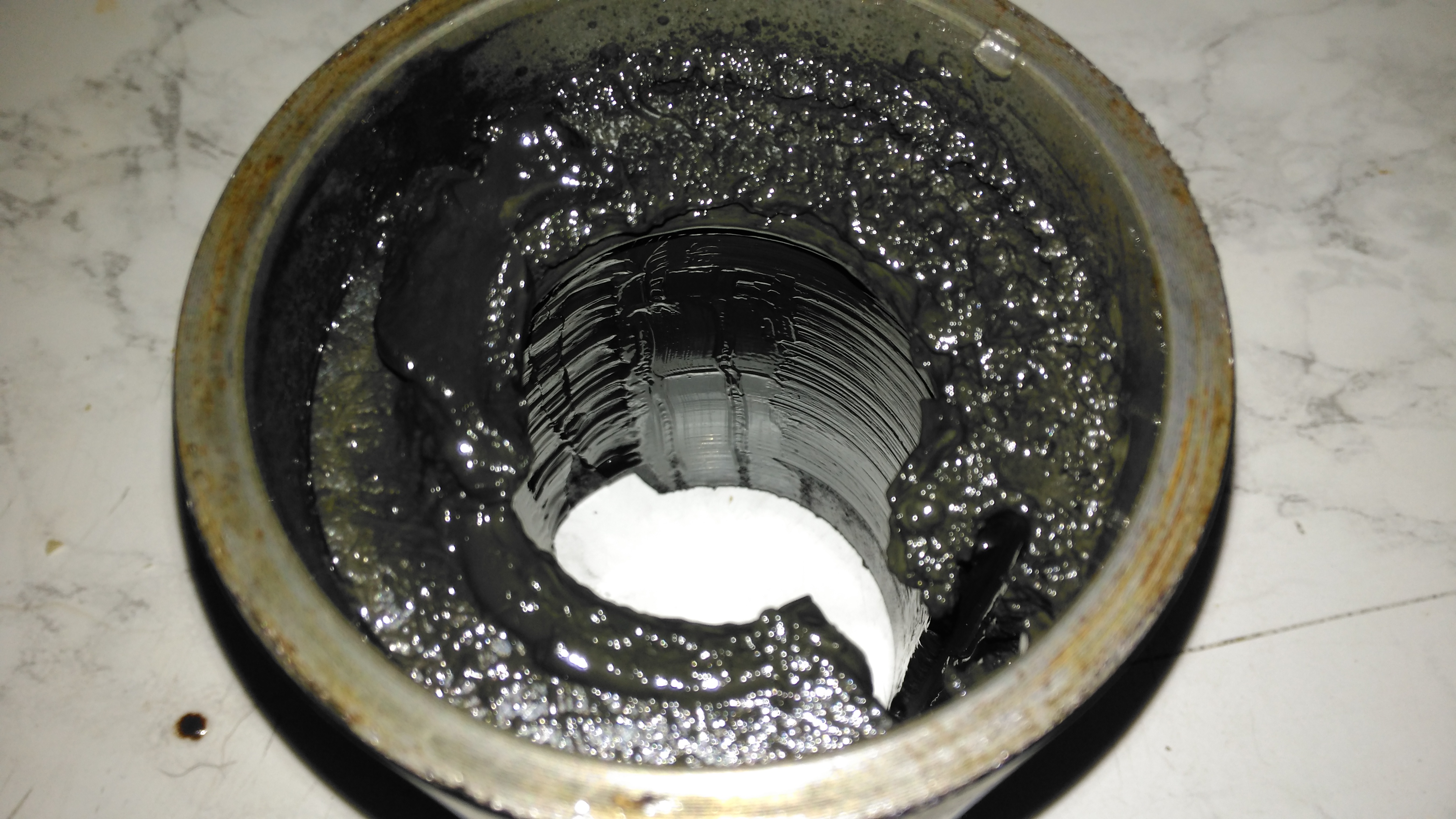
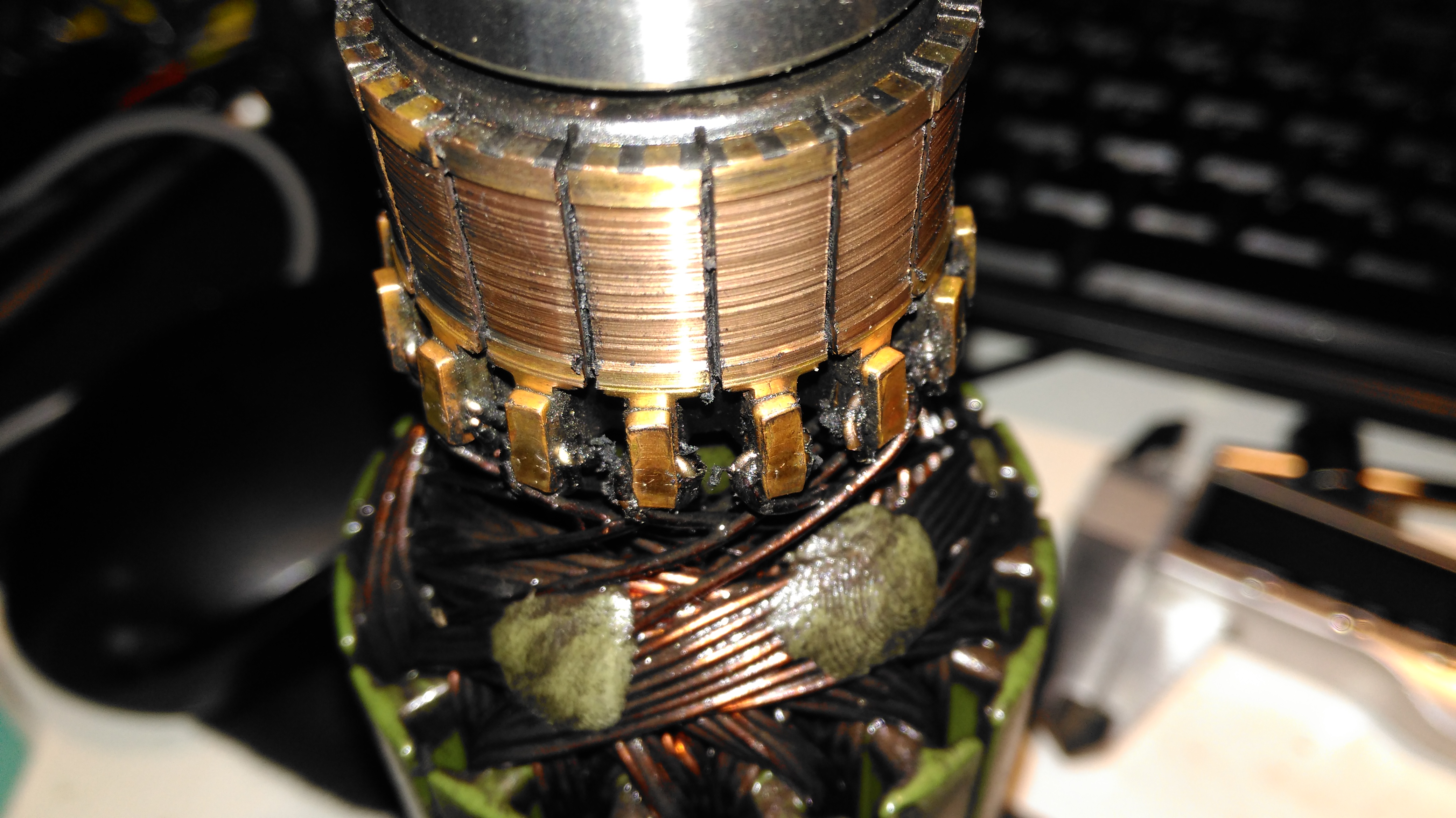
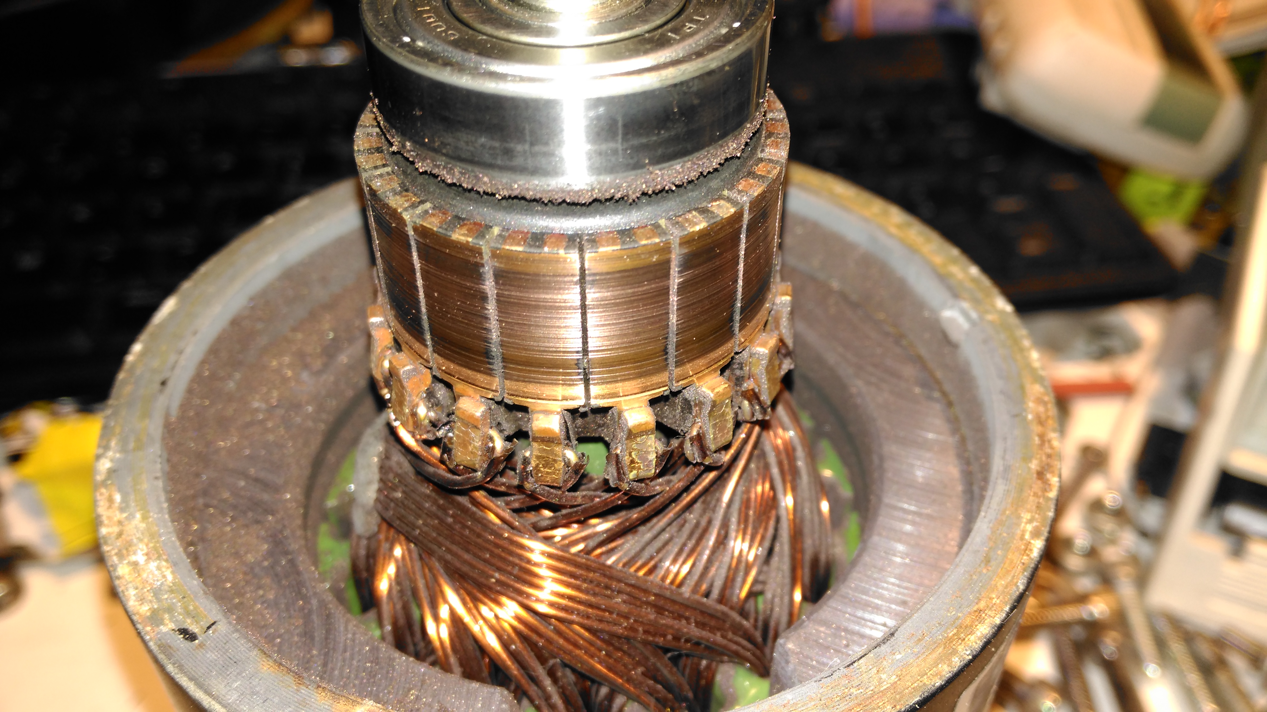
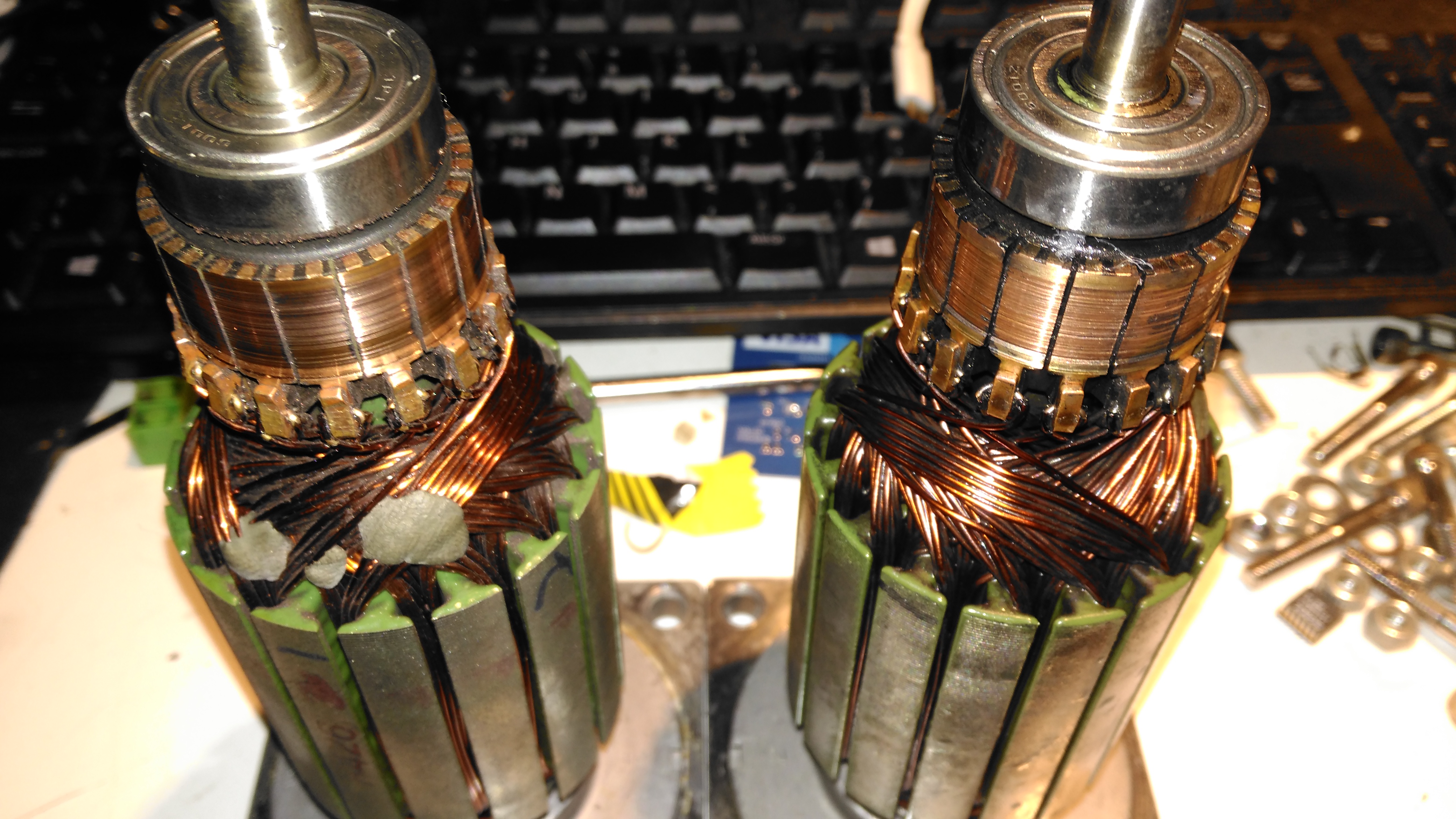
During the rebuild of the wheelchair motors for the support trolley, I found myself needing an accurate milliohm meter to test the armature windings with. Commercial instruments like these are expensive, but some Google searching found a milliohm meter project based around the Arduino from Circuit Cellar.

Circuit Diagram
Circuit Diagram

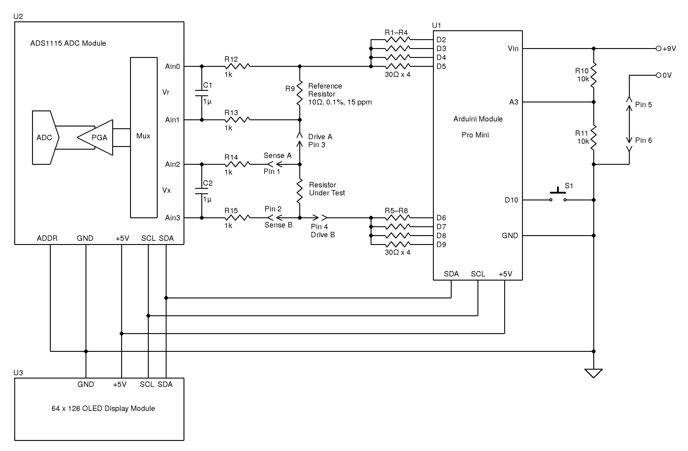
Here’s the original author’s circuit diagram, paralleling nearly all of the Arduino’s digital output pins together to source/sink the test current, an ADS1115 ADC to take more accurate readings, with the results displayed on a jellybean 128×64 OLED module. The most expensive part here is the 10Ω 0.1% 15ppm reference resistor, R9.
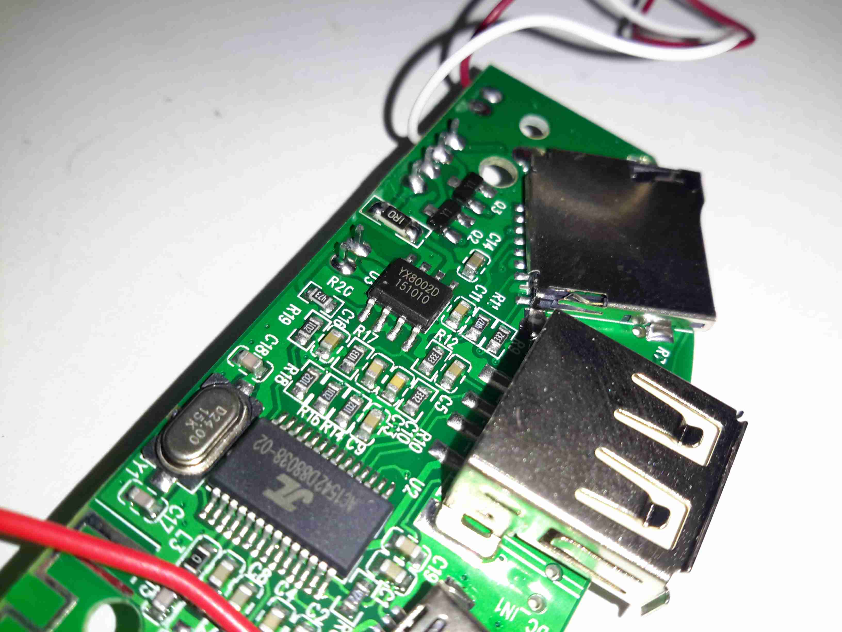
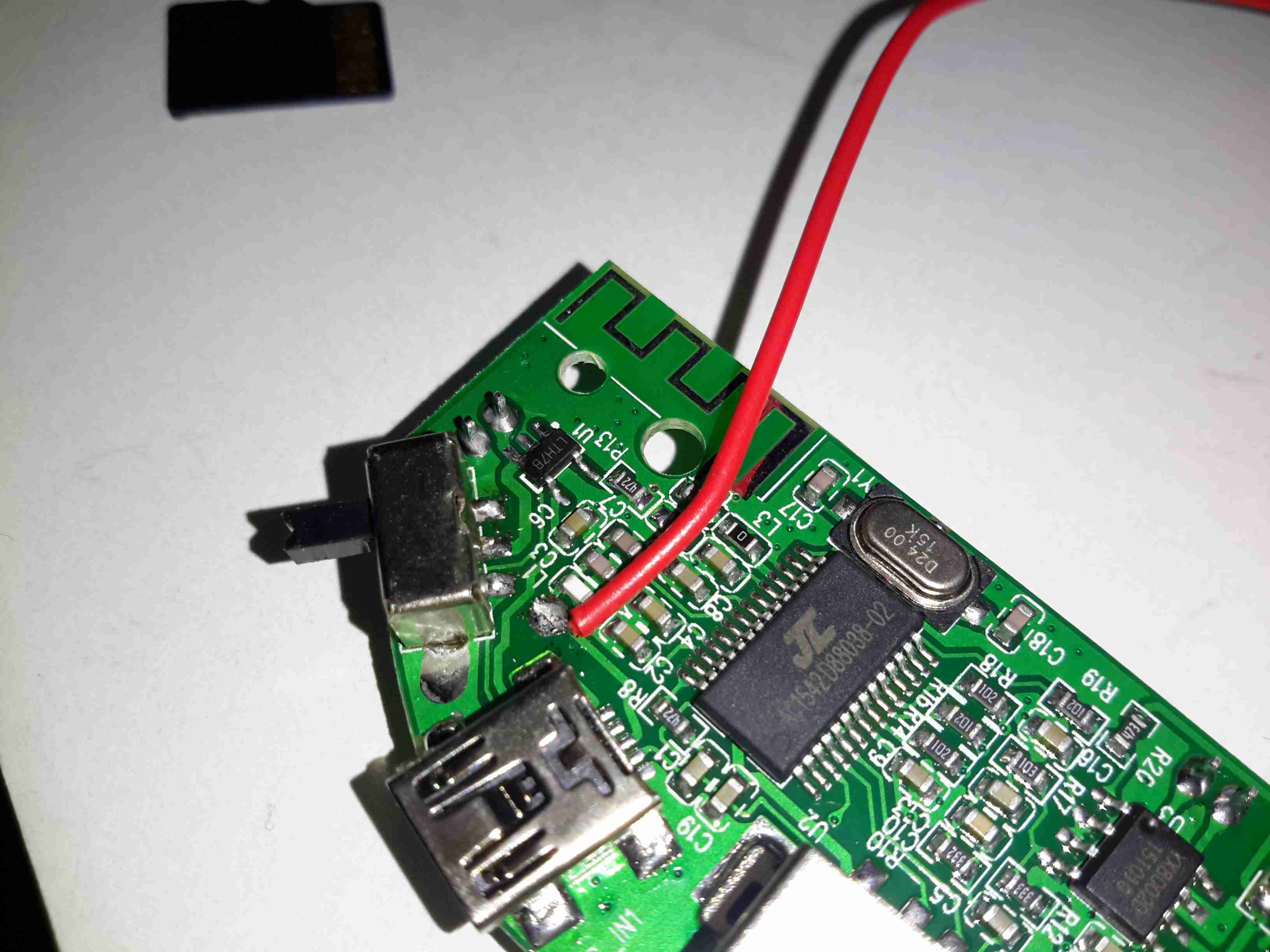
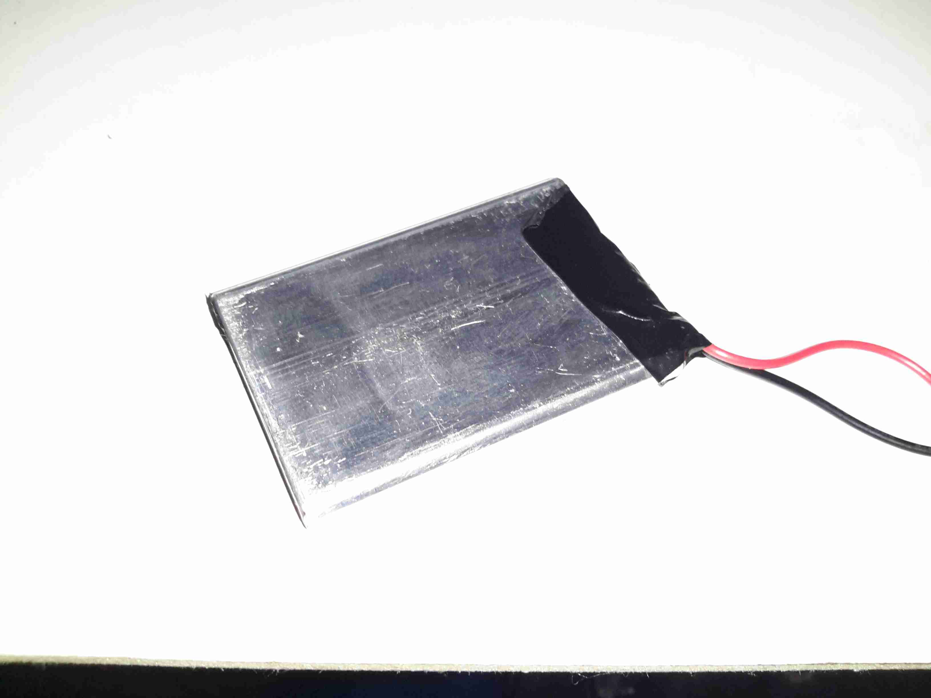
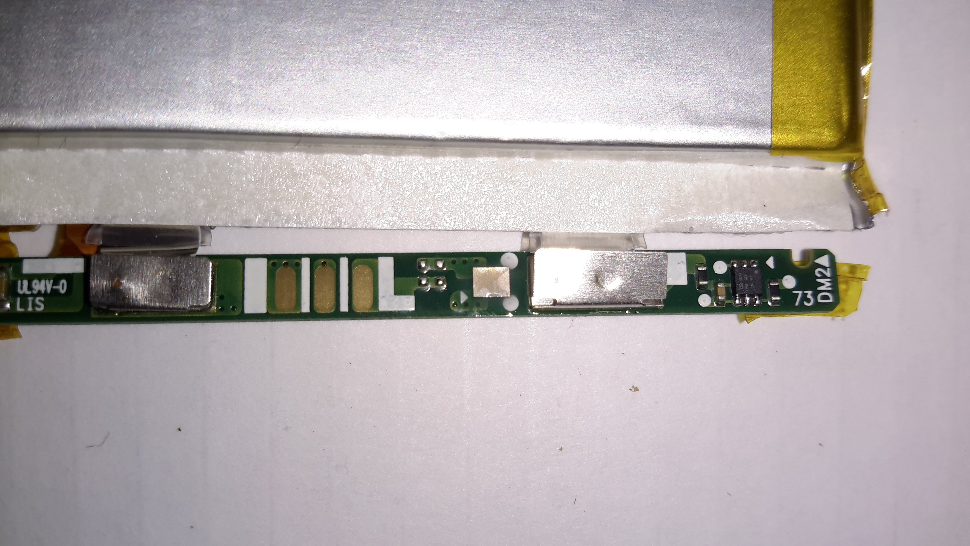
I decided to make some small adjustments to the power supply section of the project, to include a rechargeable lithium cell rather than a 9v PP3 battery. This required some small changes to the Arduino sketch, a DC-DC boost converter to supply 5v from the 3.7v of a lithium cell, a charger module for said cell, and with the battery voltage being within the input range of the analogue inputs, the voltage divider on A3 was removed. A new display icon was also added in to indicate when the battery is being charged, this uses another digital input pin for input voltage sensing.
I also made some basic changes to the way an unreadable resistance is displayed, showing “OL” instead of “—–“, and the meter sends the reading out over the I²C bus, for future expansion purposes. The address the data is directed to is set to 0x50.

I’ve not etched a PCB for this as I couldn’t be bothered with the messy etchant, so I built this on a matrix board instead.

Final Prototype
Final Prototype

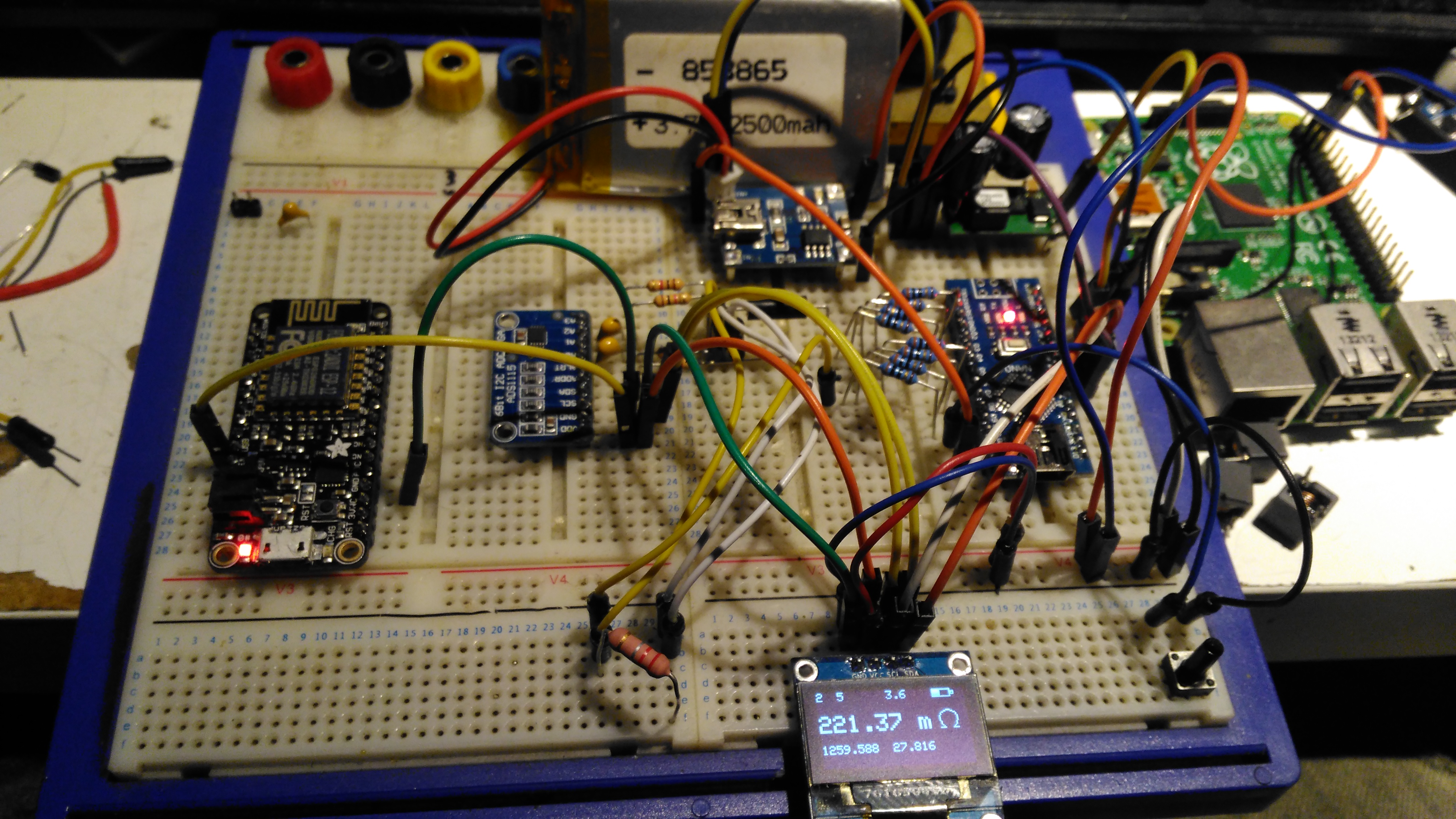
Since I made some changes to both the software and the hardware components, I decided to prototype the changes on breadboard. The lithium cell is at the top of the image. with the charger module & DC-DC converter. The Arduino Nano is on the right, the ADC & reference resistor on the left, and the display at the bottom.
The Raspberry Pi & ESP8266 module are being used in this case to discharge the battery quicker to make sure the battery level calibration was correct, and to make sure the DC-DC converter would continue to function throughout the battery voltage range.

Matrix Board Passives

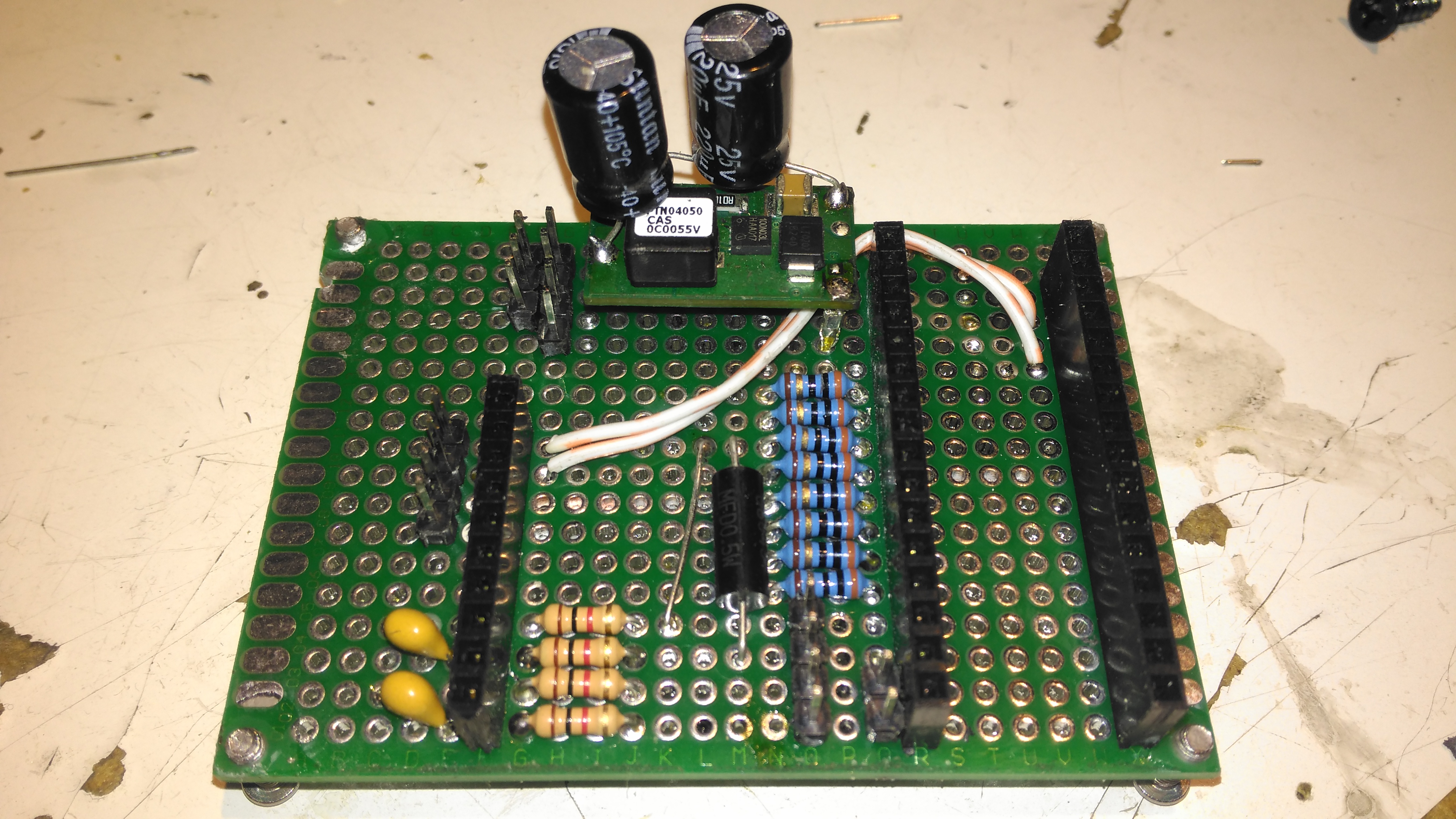
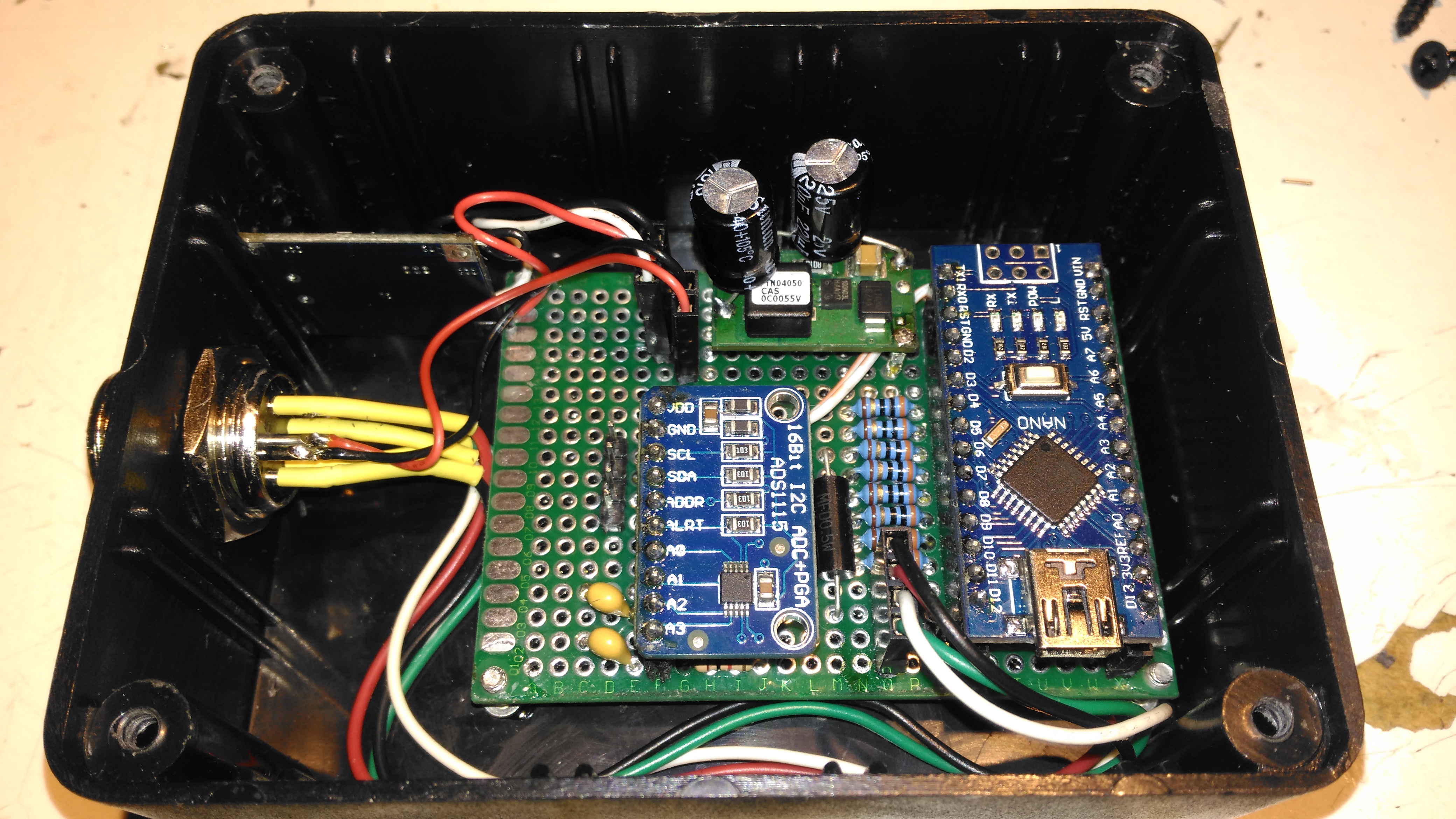
Here’s the final board with the passive components installed, along with the DC-DC converter. I used a Texas Instruments PTN04050 boost module for power as I had one spare.

Matrix Board Rear
Matrix Board Rear

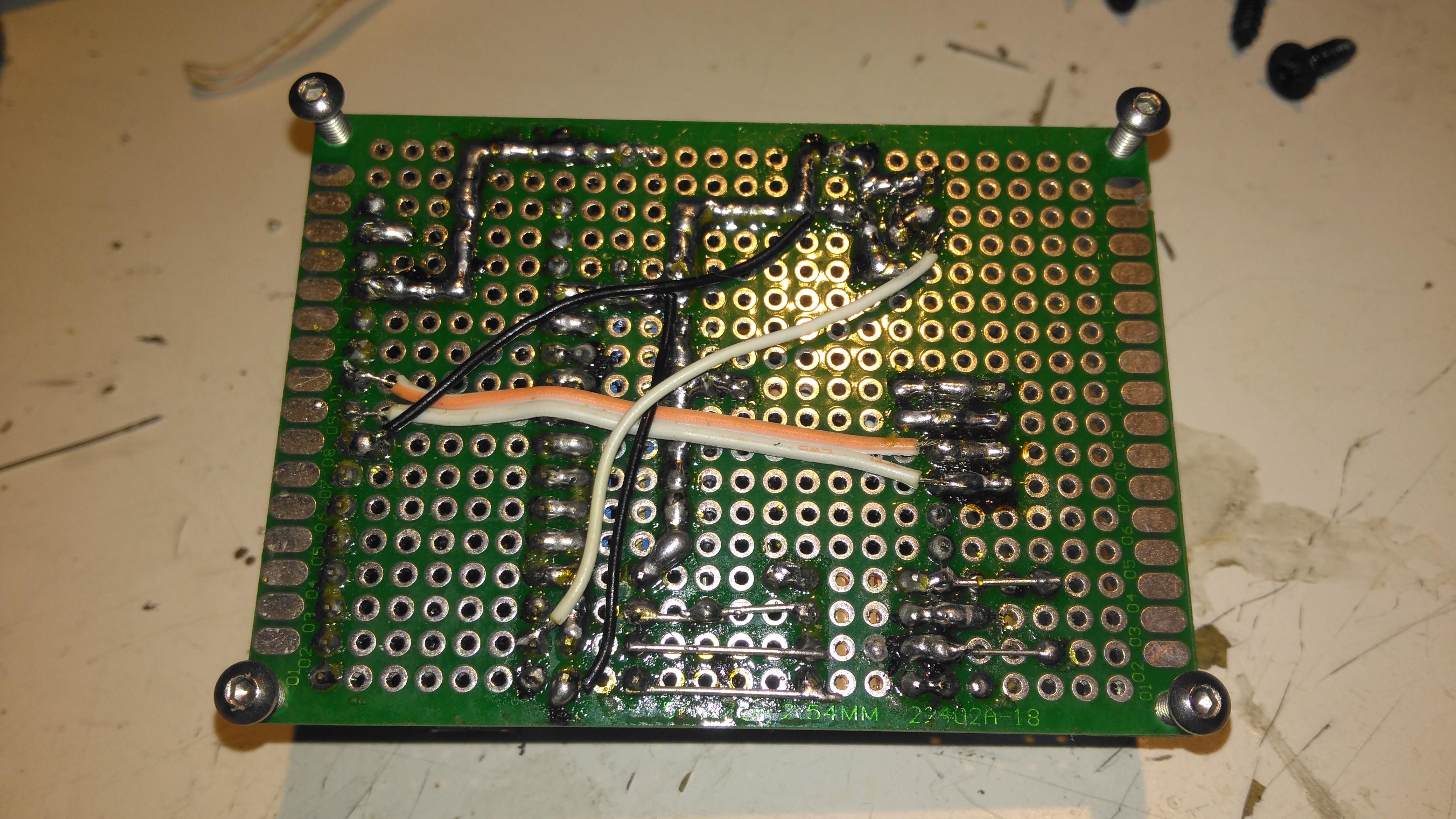
The bottom of the board has most of the wire jumpers for the I²C bus, and power sensing.

Matrix Board Modules

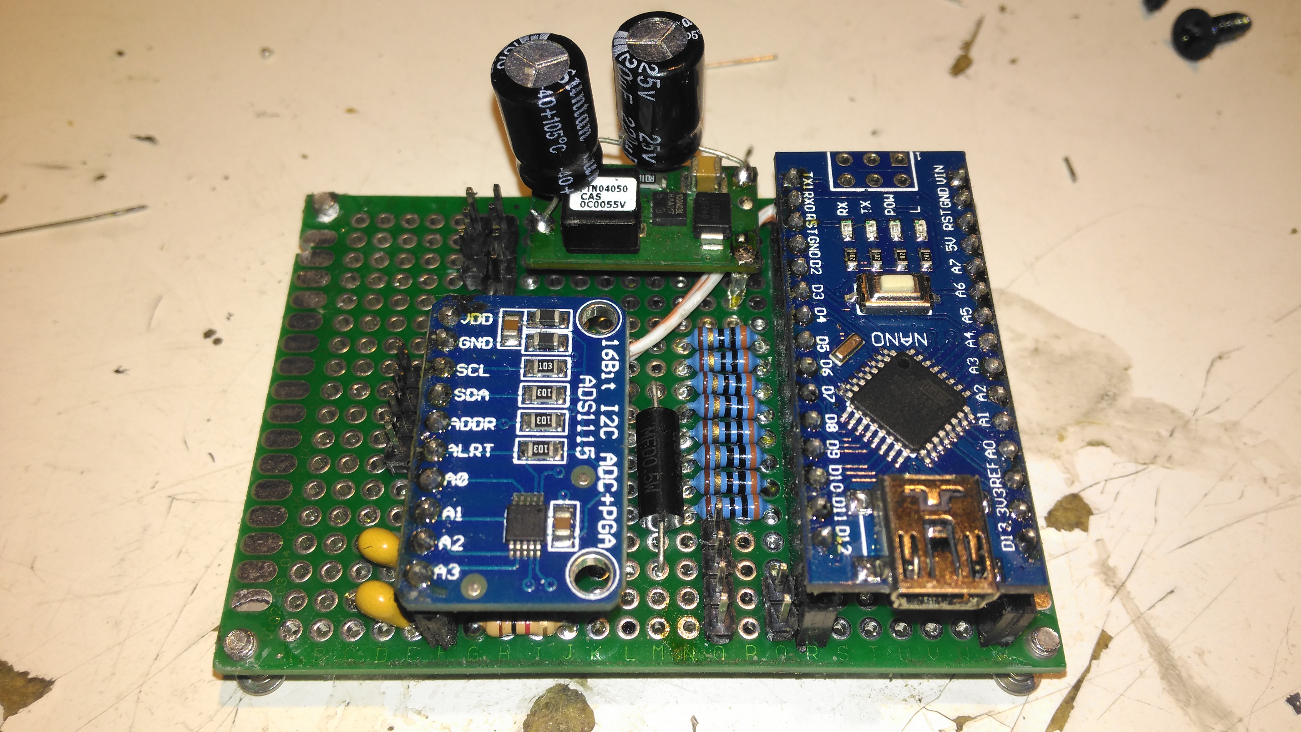
Here’s both modules installed on the board. I used an Arduino Nano instead of the Arduino Pro Mini that the original used as these were the parts I had in stock. Routing the analogue pins is also easier on the Mini, as they’re brought out to pins in the DIP footprint, instead of requiring wire links to odd spots on the module. To secure the PCB into the case without having to drill any holes, I tapped the corner holes of the matrix board M2.5 & threaded cap head screws in. These are then spot glued to the bottom of the case to secure the finished board.

Lithium Charger
Lithium Charger

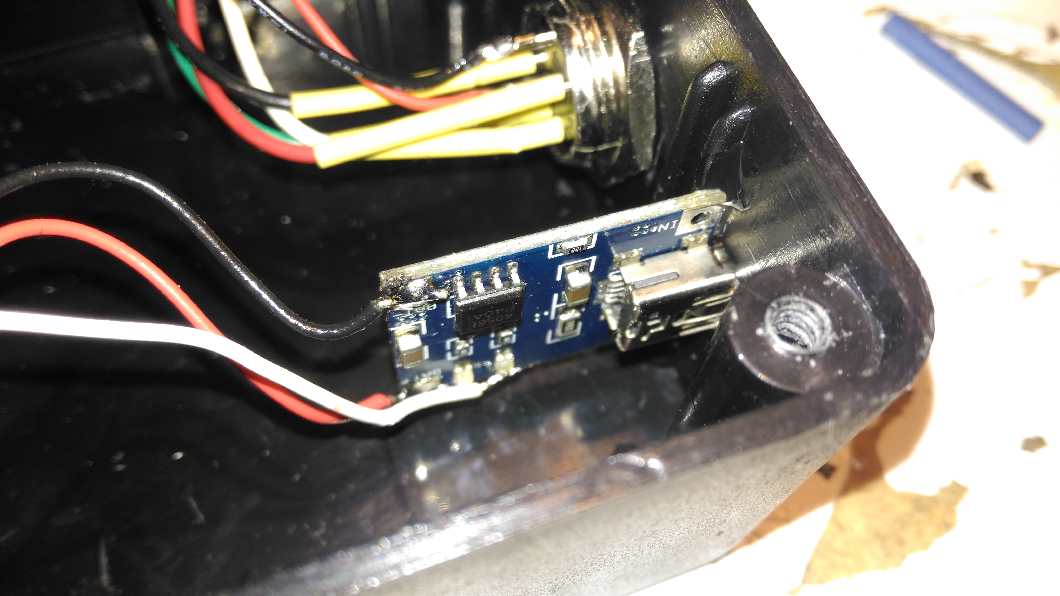
The lithium charger module is attached to the side of the enclosure, the third white wire is for input sensing – when the USB cable is plugged in a charge icon is shown on the OLED display.

Input Connections
Input Connections

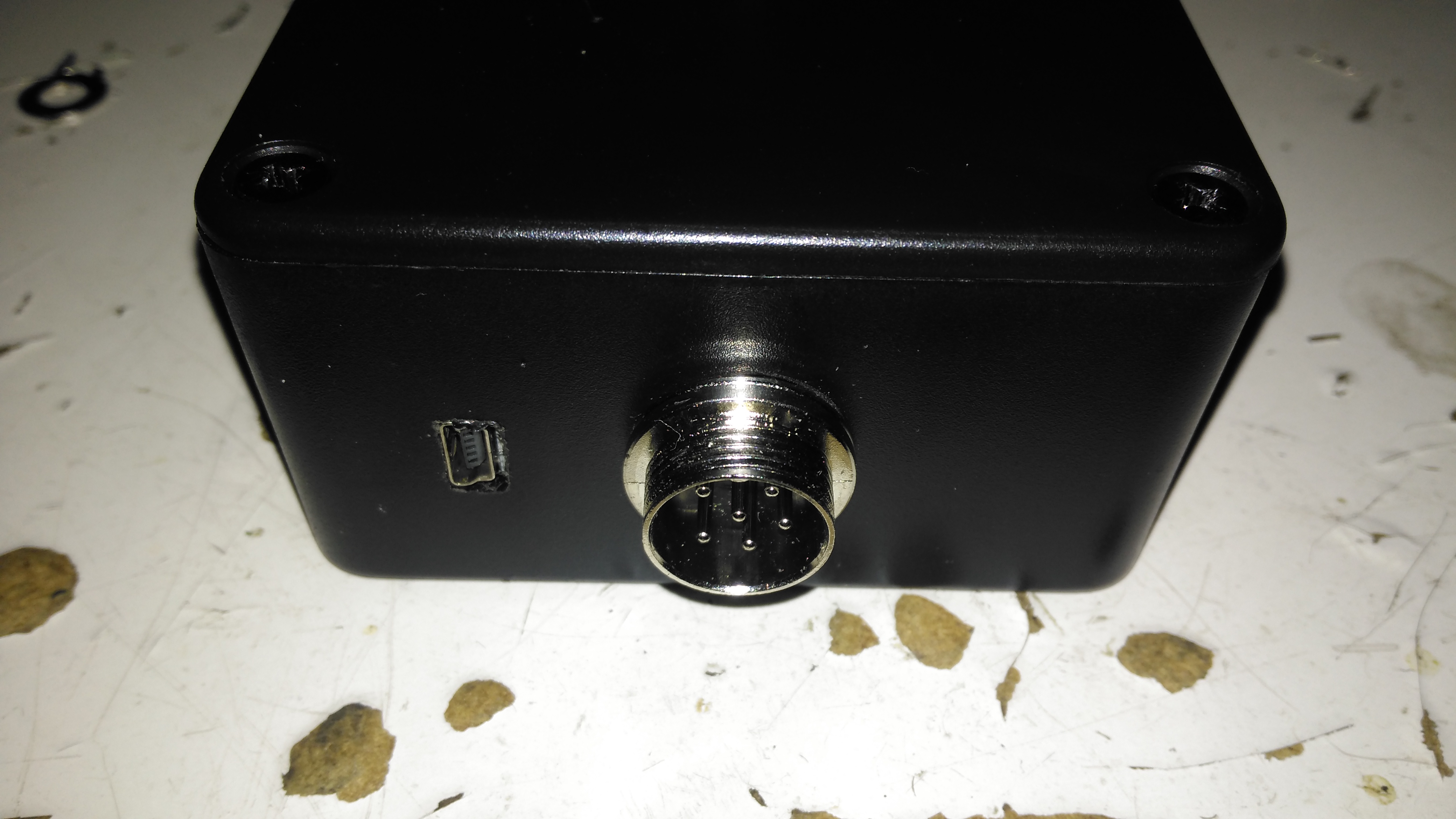
The inputs on the side of the enclosure. I’ve used the same 6-pin round connector for the probes, power is applied to the Arduino when the probes are plugged in.

Module Installed
Module Installed

Everything installed in the enclosure – it’s a pretty tight fit especially with the lithium cell in place.

Meter Top Cover
Meter Top Cover

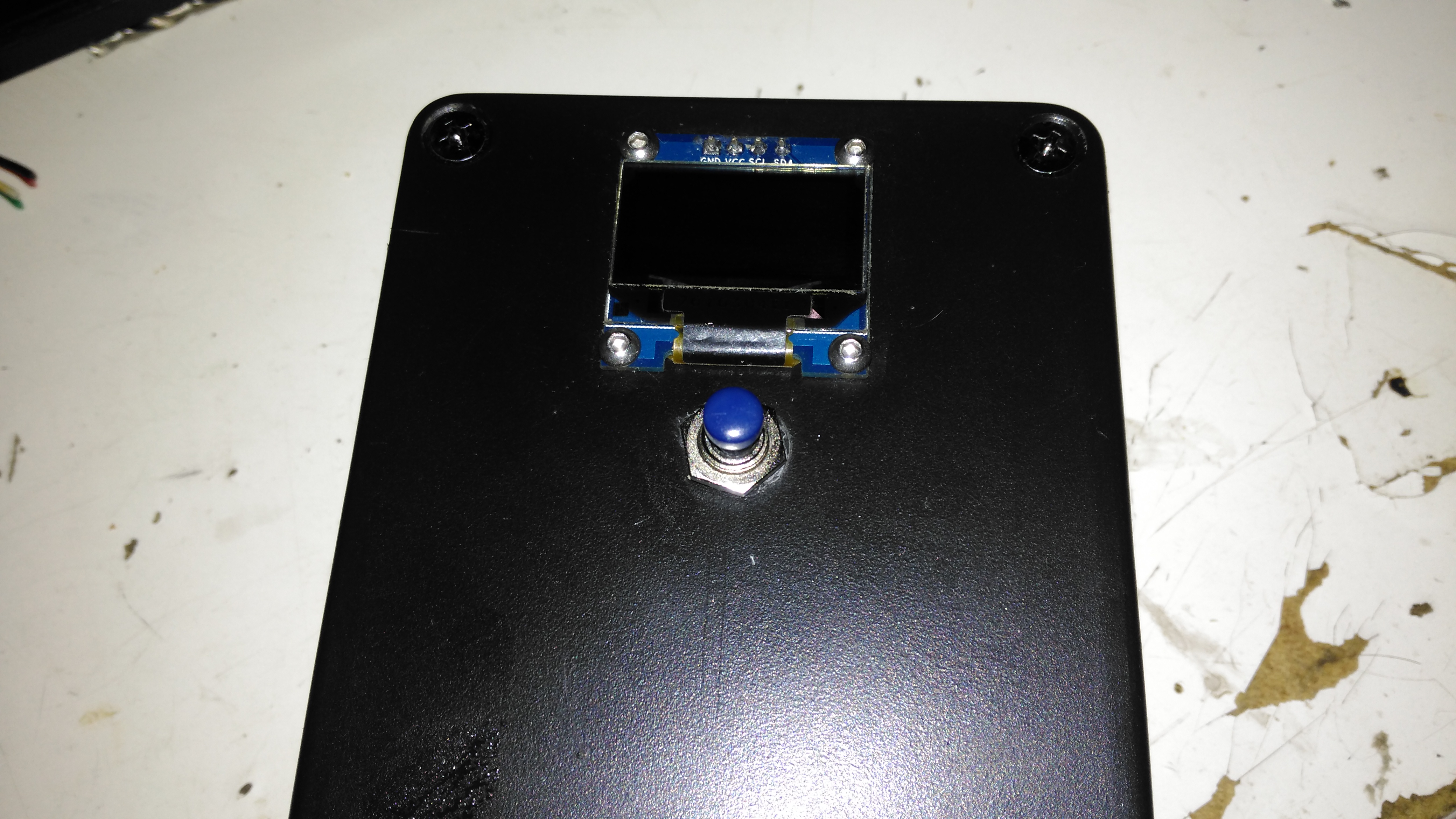
The top cover has the Measure button, and the OLED display panel, the latter secured to the case with M2.5 cap head screws.

Kelvin Clips
Kelvin Clips

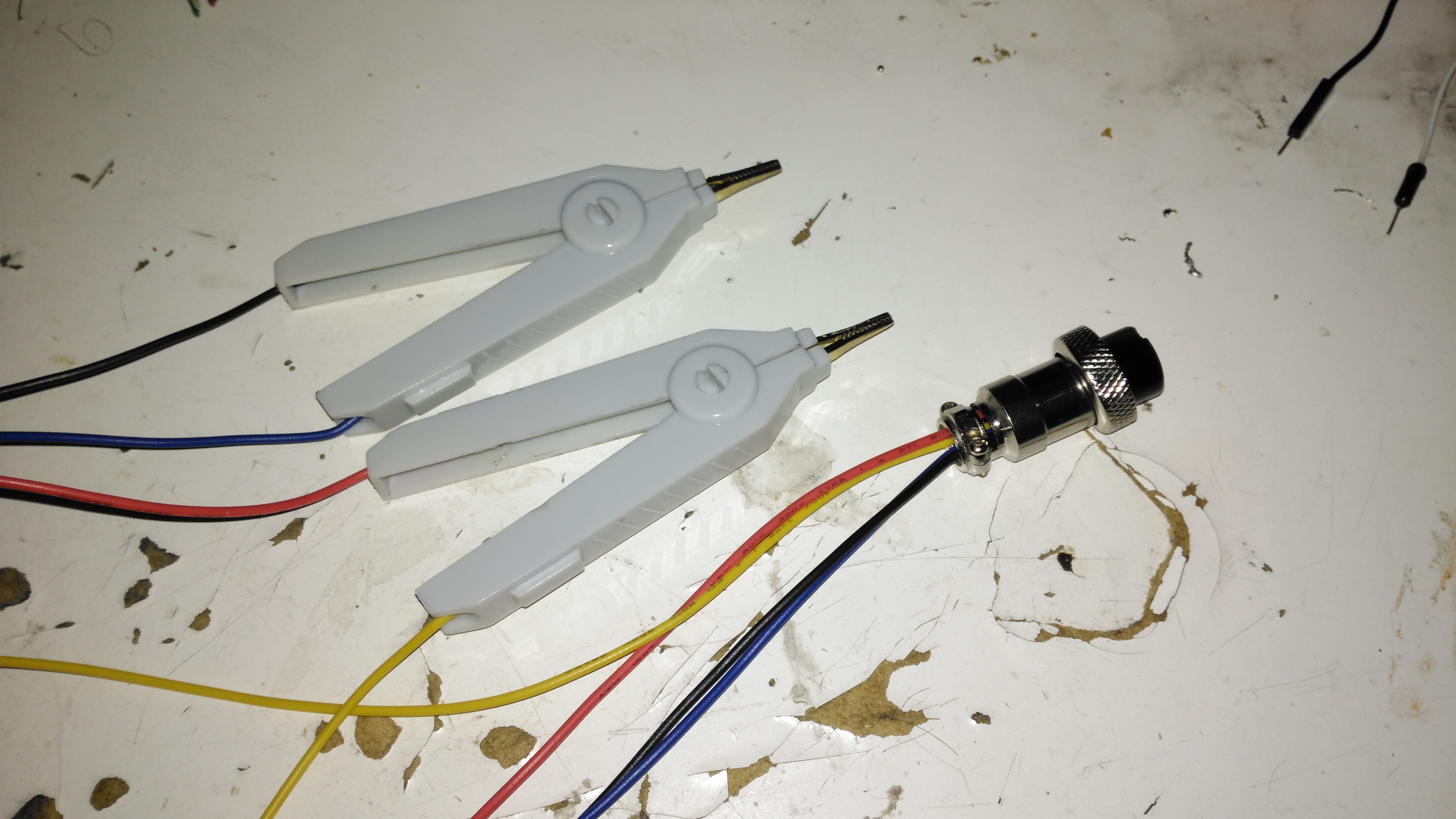
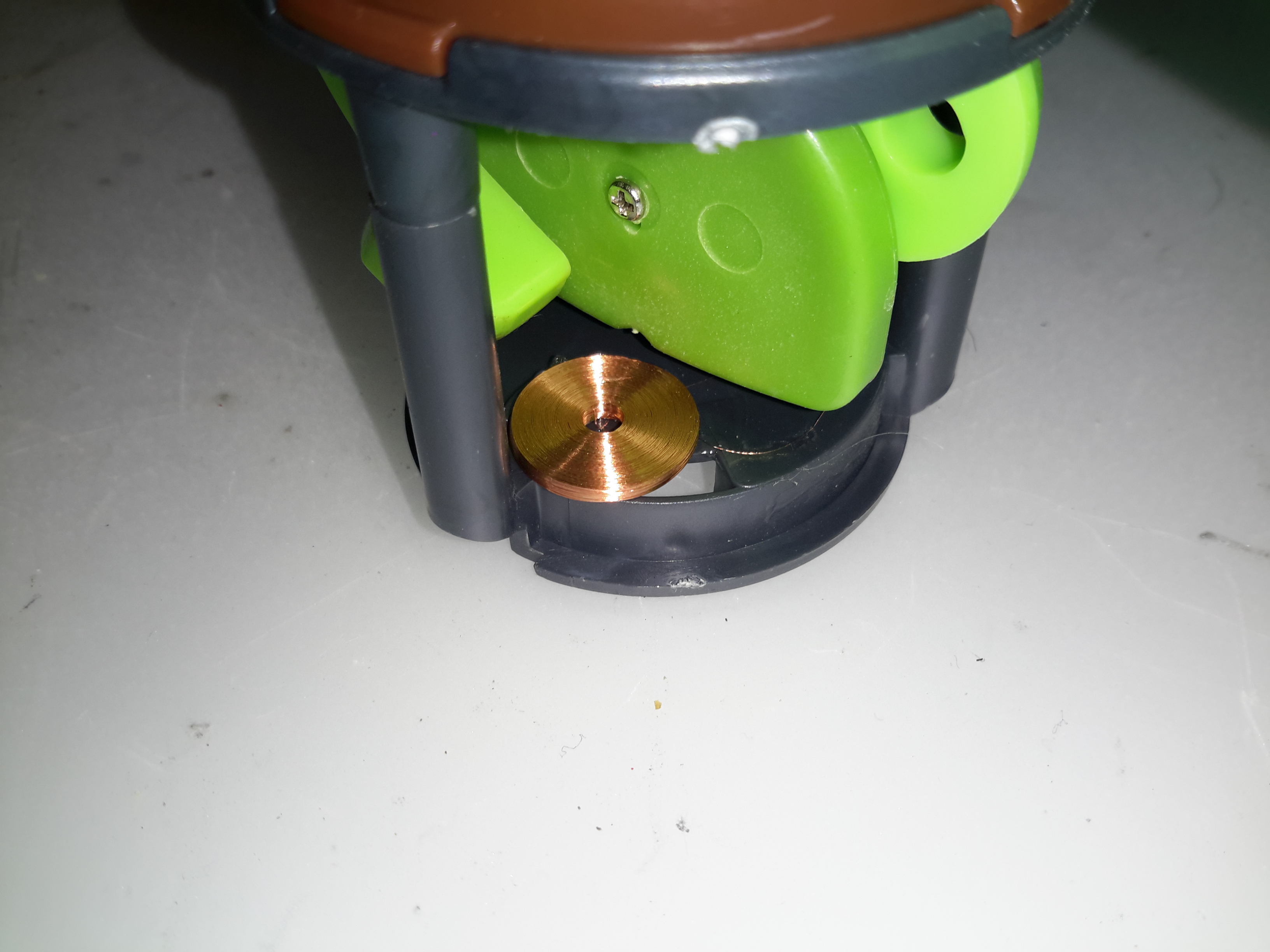
Finally, the measurement loom, with Kelvin clips. These were an eBay buy, keeping things cheap. These clips seem to be fairly well built, even if the hinges are plastic. I doubt they’re actually gold-plated, more likely to be brass. I haven’t noticed any error introduced by these cheap clips so far.

The modified sketch is below:


Posted on Leave a comment

Quick Tool Review – Engineer PA-09 Crimping Pliers

For a while now I’ve been attaching terminals such as Molex KK Dupont, & JST PH to wire ends with a lot of patience & a very fine soldering iron, however this method takes a lot of time, and with terminals like Dupont types, the terminal won’t fit into the connector body properly unless it’s crimped correctly. Official tools from the likes of JST or Molex are hilariously expensive, (~£250 for the Molex KK tool), and each tool only does a single connector series, so these are out of the picture. The cheapest available tool (~£40) for these types of terminals is the Engineer PA-09:

Engineer PA-09
Engineer PA-09

These are simple crimping pliers, with no niceties like a ratchet mechanism, but nonetheless they work very well for the cost. The PA-09 can handle terminals from 1mm-1.9mm, there is another tool, the PA-21, which crimps terminals from 1.6mm-2.5mm. The fit & finish is good – proper steel (S55C high carbon steel according to Engineer), not the steel-plated-cheese that most cheap Chinese tools are fabricated from, the handles are solid & comfortable.

Handles
Handles

The rubber handles are press-fit onto the steel frame arms of the pliers, and don’t slip off readily.

Die Head
Die Head

The dies are well formed in the steel, and seem to be machined rather than stamped on a press, however the black oxide finish hides any machining marks. The smallest 1mm dies do seem to be a little fragile as they’re so small, so wouldn’t take much abuse without shearing off.

Crimped Molex KK Pin

Here’s a Molex KK pin that’s been crimped with the PA-09. The insulation crimp has pierced the insulation slightly, but this isn’t much of a problem. The conductor crimp is nice & tight, and everything is small enough to fit correctly into the plastic connector body. The trick with these tools is getting a feel for when the crimp is done – squeeze too tightly & the contact deforms, not tightly enough & the wire will just pull out of the terminal. The official tools also crimp both the conductor & insulation at the same time, and they also hold the terminal in place while the wire is inserted. In these cheaper tools, the crimps are done separately, but they do hold on to the contact securely enough for the wire to be inserted properly with your spare hand.

Posted on 3 Comments

Wheelchair Motor Service Part 1: Teardown & Inspection

Trolley Propulsion System: Wheelchair Motor Units

So it’s time to get the propulsion system underway for the trolley, a pair of wheelchair motors were sourced for this, from HacMan. Since I don’t know how many hours are on these units, or how they’ve been treated in the past, I’m going to do a full service on them to ensure reliability. I decided on wheelchair motors due to their extreme ruggedness & heavily built components – this project when complete is going to weigh in at about 150kg!
I suspected something was amiss with one of the motors from running them under no load: the left hand wheelchair motor was heating up to the point of being too hot to touch, so this one at the very least needed some investigation.

Motor Disassembly & Assessment

Rear Cover Removed
Rear Cover Removed

With the back cover removed from the motor the electromagnetic brake is revealed. This engages when power is removed to stop the motor freewheeling, which even though it’s a wormdrive box, it will do readily if backdriven.

Electromagnetic Brake Assembly

The brake is rated 6.7W at 24v DC.

Brake Disc
Brake Disc

The brake disc is just visible between the plates of the brake here, with some green dust worn off the disc. When power is applied, the top disc, just under the magnet on top, is pulled upward against spring pressure away from the brake disc, which is attached to the motor armature.

Brake Disc
Brake Disc

Here’s the brake disc, removed from the motor. There’s only a little wear here, as I’d expect – these brakes don’t engage until the motors have come to a complete stop.

Brake Actuator
Brake Actuator

The steel disc above the magnet acts as one of the friction surfaces of the brake.

Brake Solenoid
Brake Solenoid

Finally, the solenoid is at the back, partially potted in resin. The strong coil spring in the centre applies the brakes when power is disconnected.

Gearbox Grok
Gearbox Grok

Removing the top of the gearbox reveals the state of the internals – There’s no wear at all on the gearset, but the lubricant is totally manky. The external oil seals have been leaking for some time, letting water in and grease out. The emulsified result is revolting! These gearboxes have a wormdrive first stage, the worm gear is underneath the left hand gearset. Steel spur gears then do the final gearing to the output shaft. The output gear is splined onto the output, and can slide along the shaft out of mesh – this is the freewheel clutch mechanism. At the moment it’s all obscured by the disgusting lubricant.

Input Shaft Seal
Input Shaft Seal

Here’s the failed seal on the left hand gearbox, the face damage was done by petrol immersion to clean everything up. (The seal is already compromised, so I’m not fussed about solvents eating the remaining rubber). The motor shaft is joined to the gearbox input by a rubber coupling.

Output Shaft Seal
Output Shaft Seal

The output shaft seals seem to be still OK, there has been some seepage past the collar that the shaft rides in, but nothing more. This can be resealed with some Loctite bearing sealant. The sleeve is held into the gearbox by the wheel hub when in operation, but this doesn’t seal the gap unfortunately. I don’t know why the manufacturer didn’t just machine the shaft to that larger diameter, instead of using an extra sleeve to accommodate the seal.

Bore Seals
Bore Seals

The bore seals covering the ends of the shafts are also fine, which is a good thing, since I can’t seem to find replacements for these anywhere. The input shaft seals will be replaced on both gearboxes though.

Motor Contamination
Motor Contamination

The oil seal must have been leaking for a long while! This is the gearbox end of the wheelchair motor frame, completely clogged with grease. Luckily only a small amount has made it down past the armature to the brushgear.

Damaged Commutator
Damaged Commutator

The commutator of this motor is badly damaged, and the brushes are very worn. This has been caused by the gearbox oil seal failing, and contaminating the motor internals with lubricant. The undercut between the segments is all but gone – filled with an abrasive mixture of brush dust, copper dust & old lubricant. Some repair work will be required here.

Second Motor
Second Motor

Here’s the brushgear removed from the second wheelchair motor, this one looks much more normal, and there’s not as much wear on the brushes or the commutator. Just the usual coating of brush dust.

Armatures
Armatures

Here’s both armatures together, with the contaminated one on the right, after some cleaning to remove most of the greasy old grok & brush dust from everything. The windings on the damaged left hand wheelchair motor haven’t darkened, which I would expect from severe overheating damage, so I’m hoping this armature is OK, and won’t require a rewind. Using an ohmmeter on these windings doesn’t tell me much – there’s only 7 turns of 0.86mm (20AWG) magnet wire in each coil, so they read as a dead short anyway. There was some leakage between the windings and the core before I cleaned things up – this was in the high (28+) megohms range, but this seems to have cleared now I’ve given things a real good cleaning.

More to come when new bearings & seals arrive!

Posted on 4 Comments

DIY Eberspacher Glowplug Screens: The Test Of Time

Some time ago I did a couple of posts on cheapening up the maintenance of Eberspacher hot air heaters by making the glow plug screens myself. Now one of my pieces of stainless mesh has been in the heater for nearly a year, and the heater is starting to get a bit smoky on a cold start. This is usually a sign that the screen isn’t allowing the fuel to vaporise quick enough for the glow plug to ignite the flame, because it’s becoming blocked. So far the heater has had about 150L of diesel through it with my DIY screen.

Old Screen
Old Screen

After removing the plug, here’s what’s left of the screen. The bottom end has completely disintegrated, but this is to be expected – OEM screens do the same thing as this end is exposed to the most heat in the burner. There’s quite a bit of coke buildup on the top end of the screen around the fuel nozzle, again this isn’t surprising, as this is the coolest part of the heater not all the heavier fractions of the diesel fuel have the chance to vaporise.

Innards
Innards

Looking further down into the mixing tube of the main burner, everything looks good. There’s a coating of soot in there, but no tar-like build up that would tell me the unit isn’t burning properly. Another advantage of making my own screens is that they’re much easier to extract from the hole once they’ve been in there for months. The OEM screens have a stainless ring spot welded to the mesh itself to hold it’s shape, and once there’s enough fuel residue built up the entire mess seizes in place, requiring some sharp pokey tools & some colourful language to remove. The single loop of mesh held in place by it’s own spring pressure is much easier to remove as it collapses easily.

New 80 Mesh Screen
New 80 Mesh Screen

I’ve decided to change the mesh size of the screen while I’m in here, in this case to 80 mesh, which is much closer to the OEM screen size. There doesn’t seem to be much of a difference so far in either the starting or running capability of the heater, although the thicker wire of this screen might last longer before disintegrating at the burner end.

Posted on Leave a comment

eBay Special – LED Disco Light With Built In MP3 Player

Here’s an eBay oddity – it’s got the same light & lens mechanism as the cheap “disco light” style bulbs on eBay, but this one is battery powered & has a built in MP3 player.

MP3 Disco Light
MP3 Disco Light

This device simply oozes cheapness. The large 4″ plastic dome lens sits on the top above the cheap plastic moulding as a base, which also contains the MP3 player speaker.

Controls
Controls

There are few controls on this player, the volume buttons are combined with the skip track buttons, a long press operates the volume control, while a short press skips the tracks. Several options for getting this thing to play music are provided:

  • Bluetooth – Allows connection from any device for bluetooth audio
  • USB – Plugging in a USB flash drive with MP3 files
  • SD Card – Very similar to the USB flash drive option, just a FAT32 formatted card with MP3 files
  • Aux – There’s no 3.5mm jack on this unit for an audio input, instead a “special” USB cable is supplied that is both used to charge the built in battery & feed an audio signal. This is possible since the data lines on the port aren’t used. But it’s certainly out of the ordinary.
Top Removed
Top Removed

The top comes off with the removal of a single screw in the centre of the lens. The shaft in the centre that holds the lens is attached to a small gear motor under the LED PCB. There’s 6 LEDs on the board, to form an RGB array. Surprisingly for a very small battery powered unit these are bright to the point of being utterly offensive.

Mainboard
Mainboard

Here’s the mainboard removed from the plastic base. There’s not much to this device, even with all the options it has. The power switch is on the left, followed by the Mini-B USB charging port & aux audio input. The USB A port for a flash drive is next, finishing with the µSD slot. I’m not sure what the red wire is for on the left, it connects to one of the pins on the USB port & then goes nowhere.

Audio Amplifier
Audio Amplifier

The audio amplifier is a YX8002D, I couldn’t find a datasheet for this, but it’s probably Class D.

Main Chipset
Main Chipset

Finally there’s the main IC, which is an AC1542D88038. I’ve not been able to find any data on this part either, it’s either a dedicated MP3 player with Bluetooth radio built in, or an MCU of some kind.The RF antenna for the Bluetooth mode is at the top of the board.
Just behind the power switch is a SOT23-6 component, which should be the charger for the built in Lithium Ion cell.

Lithium Ion Cell
Lithium Ion Cell

The cell itself is a prismatic type rated in the instructions at 600mAh, however my 1C discharge test gave a reading of 820mAh, which is unusual for anything Li-Ion based that comes from eBay 😉
There is cell protection provided, it’s under the black tape on the end, nothing special here.

The main issue so far with this little player is the utterly abysmal battery life – at full volume playing MP3s from a SD card, the unit’s current draw is 600mA, with the seizure & blindness-inducing LEDs added on top, the draw goes up to about 1200mA. The built in charger is also not able to keep up with running the player while charging. This in all only gives a battery life of about 20 minutes, which really limits the usability of the player.

Posted on Leave a comment

eBay Chinese Chassis Power Supply S-400-12 400W 12v 33A

S-400-12 PSU
S-400-12 PSU

Here’s a cheap PSU from the treasure trove of junk that is eBay, rated at a rather beefy 400W of output at 12v – 33A! These industrial-type PSUs from name brands like TDK-Lambda or Puls are usually rather expensive, so I was interested to find out how much of a punishment these cheap Chinese versions will take before grenading. In my case this PSU is to be pushed into float charging a large lead acid battery bank, which when in a discharged state will try to pull as many amps from the charger as can be provided.

Rating Label
Rating Label

These PSUs are universal input, voltage adjustable by a switch on the other side of the PSU, below. The output voltage is also trimmable from the factory, an important thing for battery charging, as the output voltage needs to be sustained at 13.8v rather than the flat 12v from the factory.

Input Voltage Selector
Main Terminal Block
Main Terminal Block

Mains connections & the low voltage outputs are on beefy screw terminals. The output voltage adjustment potentiometer & output indicator LED are on the left side.

Cooling Fan
Cooling Fan

The cooling fan for the unit, which pulls air through the casing instead of blowing into the casing is a cheap sleeve bearing 60mm fan. No surprises here. I’ll probably replace this with a high-quality ball-bearing fan, to save the PSU from inevitable fan failure & overheating.

PCB Bottom
PCB Bottom

The PCB tracks are generously laid out on the high current output side, but there are some primary/secondary clearance issues in a couple of places. Lindsay Wilson over at Imajeenyus.com did a pretty thorough work-up on the fineries of these PSUs, so I’ll leave most of the in-depth stuff via a linky. There’s also a modification of this PSU for a wider voltage range, which I haven’t done in this case as the existing adjustment is plenty wide enough for battery charging duty.

Bare PCB
Bare PCB

The PCB is laid out in the usual fashion for these PSUs, with the power path taking a U-route across the board. Mains input is lower left, with some filtering. Main diode bridge in the centre, with the voltage selection switch & then the main filter caps. Power is then switched into the transformer by the pair of large transistors on the right before being rectified & smoothed on the top left.

Main Switching Transistors

The pair of main switching devices are mounted to the casing with thermal compound & an insulating pad. To bridge the gap there’s a chunk of aluminium which also provides some extra heatsinking.

SMPS Drive IC & Base Drive Transformer

The PSU is controlled by a jelly-bean TL494 PWM controller IC. No active PFC in this cheap supply so the power factor is going to be very poor indeed.

Input Protection
Input Protection

Input protection & filtering is rather simple with the usual fuse, MOV filter capacitor & common mode choke.

Main Output Rectifiers

Beefy 30A dual diodes on the DC output side, mounted in the same fashion as the main switching transistors.

Output Current Shunt

Current measurement is done by these large wire links in the current path, selectable for different models with different output ratings.

Hot Glue Support
Hot Glue Support

The output capacitors were just floating around in the breeze, with one of them already having broken the solder joints in shipping! After reflowing the pads on all the capacitors some hot glue as flowed around them to stop any further movement.

This supply has now been in service for a couple of weeks at a constant 50% load, with the occasional hammering to recharge the battery bank after a power failure. at 13A the supply barely even gets warm, while at a load high enough to make 40A rated cable get uncomfortably warm (I didn’t manage to get a current reading, as my instruments don’t currently go high enough), the PSU was hot in the power semiconductor areas, but seemed to cope at full load perfectly well.

Posted on Leave a comment

Inductive Hour Counter / Tachometer – Petrol Engines

As one of my current projects involves a small petrol engine – a Honda GX35 clone, I figured an hour counter would be very handy to keep an eye on service intervals. (More to come on the engine itself later on). I found a device that would suit my needs on good old eBay.

Inductive Engine Monitor

These engine monitors are pretty cheap, at about £4. The sensing is done by a single heat-resistant silicone wire, that wraps around the HT lead to the spark plug. The unit can be set for different firing intervals via the buttons. In the case of most single-cylinder 4-stroke engines, the spark plug fires on every revolution – wasted-spark ignition. This simplifies the ignition system greatly, by not requiring the timing signal be driven from 1/2 crankshaft speed. The second “wasted” spark fires into the exhaust stroke, so has no effect.

Internals
Internals

The back cover is lightly glued into place with a drop of cyanoacrylate in opposite corners, but easily pops off. The power is supplied by a soldered-in 3v Lithium cell. The main microcontroller has no number laser etched on to it at all – it appears it skipped the marking machine.

Input Filtering
Input Filtering

The input from the sensing wire comes in through a coupling capacitor & is amplified by a transistor. It’s then fed into a 74HC00D Quad 2-Input NAND gate, before being fed into the microcontroller.

Pickup
Pickup

The pickup wire is simply wound around the spark plug lead. I’ve held it in position here with some heatshrink tubing. Heat in this area shouldn’t be an issue as it’s directly in the airflow from the flywheel fan.

Posted on 2 Comments

CRT Flyback / Line Output Transformer Destructive Teardown

Small Flyback Transformer

Here’s a small flyback / Line Output Transformer from a portable colour TV set. Usually these transformers are vacuum potted in hard epoxy resin & are impossible to disassemble without anything short of explosives. (There are chemical means of digesting cured epoxies, but none of them are pleasant). This one however, was potted in silicone, so with some digging, the structure of the transformer can be revealed.

Cap Removed
Cap Removed

The cap was glued on to the casing, but this popped off easily. The top of the core is visible in the silicone potting material.

The Digging Starts
The Digging Starts

A small screwdriver was used to remove the potting material, while trying not to damage the winding bobbin & core too badly. The bulge in the casing that I originally thought might house a voltage multiplier turns out to be totally empty. The white plastic bobbin is becoming visible around the core.

Bobbin
Bobbin

After some more digging & a lot of mess later, the entire transformer is revealed. The primary & auxiliary secondaries are visible at the bottom of the transformer, next to the pins. These transformers have multiple windings, as they’re used not only for supplying the final anode voltage of several Kilovolts to the CRT, but many of the other associated voltages, for the heater, grids, focus electrodes, etc. These lower voltage windings are on the same part of the core as the primary.
Above those is the main high voltage secondary winding, which looks to be wound with #38-#40AWG wire (about the thinnest available, at 0.07mm diameter. This is wound in many sections of of a few hundred turns each to increase the insulation resistance to the high voltage. The main anode wire emerges from the top of the bobbin.

Output Rectifier
Output Rectifier

Hidden in a recess at the top is the main HV rectifier, which on this small transformer is a single device (it’s probably not internally, most likely a series stack of diodes to get the PIV rating required).

Posted on Leave a comment

Cheapo Special – Solar Animated Flowers

Solar Flowers
Solar Flowers

These solar flowers were being sold off at my local Tesco, a pair of them appeared thanks to my child 😉
They have a small solar panel on top, when they’re exposed to bright light, the flower & leaves move as if they’re being blown in a breeze.
Since one of them didn’t work, I figured I’d tear it down.

Solar Cell
Solar Cell

The solar cell on the top is similar if not identical to that used on a cheap calculator.

Controller
Controller

Not much to the control PCB. Just an electrolytic for smoothing the DC coming from the solar cell & a COB IC.

Electromagnet Coil
Electromagnet Coil

The IC drives this coil of extremely fine wire, glued to the base of the housing. Attached to the green plastic arm should be a magnet – this one has never worked as the magnet is missing. at 50p a piece, a magnet would cost me more than the whole device. So it’s the bin for this one.

Posted on 2 Comments

Tool Review – eBay Terminal Crimps

Soft Case
Soft Case

I recently decided to restock my toolkit, as there are plenty of jobs I need to sort that require the use of crimp terminals, so eBay again came to the rescue.
In my experience, cheap tools of any flavour are usually universally shite – I’ve had drill bits made out of a metal softer than aluminium, that unwind back into a straight flute bits as soon as they’re presented with anything harder to drill through than Cheese. Ditto for screwdrivers. But for once the far eastern factories seem to have done a reasonable job on this crimp tool set.

eBay Crimping Tools
eBay Crimping Tools

These are ratchet type crimping pliers, with interchangable heads so many different types of terminals can be used. A handy Philips screwdriver is included in the kit for changing the dies.

Large Dies
Large Dies

The largest dies in the set can handle cable up to 25mm² – just about the bottom end of main battery cables, which is very handy.

Medium Dies
Medium Dies

Smaller sets of dies are provided for other types of terminals.

Small Dies
Small Dies

I’m not precisely sure which type of terminals these dies fit – the profile is a bit unusual.

Tiny Dies
Tiny Dies

The smallest dies in the set are good for extremely small wires – down to 0.5mm

Automotive Dies
Automotive Dies

The pliers are supplied with the standard colour-coded automotive dies installed. Sometimes these terminals never crimp properly, as the dies just effectively crush the copper tube of the terminal, so more often than not the wire strands are just forced out of the terminal as the crimp is made, leaving a bad connection.

These are even better than the ratchet-type crimp tools at the local Maplin Electronics – the set of those I have just distorts when a large crimp is made, so the terminal never gets a full crimp. The steel is not stiff enough to handle the forces required.

Example Crimp
Example Crimp

Here’s a couple of large crimps on 6mm² cable attached to an ammeter. The crimps are nice & tight & hold onto the cable securely. The insulating sleeve on the terminals also hasn’t been cut through by the dies, which is often a problem on cheap crimp tools.

Modular He-Ne Laser Power Supply

Description and Schematic

SG-HM2 is a modular He-Ne laser power supply based on IC-HI1 with some minor enhancements. The first version is for laser tubes up to approximately 1 mW (2 mW with trivial modifications) but it should be straightforward to go to 5 mW or even higher power tubes by replacing the SG-HM2 HV Module (HVM2-1) with one with a higher voltage and current rating, along with a higher power MOSFET and minor component value changes to the Control Module (suggestions below). I have added an adjustment for tube current, a current limiting resistor and Zener to protect against output short circuits, an enable input (ground to turn on), a bleeder resistor to virtually eliminate the shock hazard after the power supply is turned off, and power and status LEDs.

  • Get the schematic for SG-HM2 (1 mW version) in PDF format: [download id=”5610″]

Modifying SG-HM2 for Higher Power He-Ne Laser Tubes

The following are guidelines for modifying SG-HM2 to drive various power He-Ne lasers. The PCB layout below with two versions of the HV Module should accommodate He-Ne laser tubes up to 10 mW. All assume input of around 12 V though a higher power system can generally run lower power lasers at reduced input voltage. If operation at rated power on another input voltage is desired, the number of turns on the inverter transformer can be adjusted accordingly. As noted above, the 1 mW HV Module (HVM2-1) should run tubes up to about 2 mW, though increasing the µF values of some of the HV capacitors may be desirable to reduce ripple at the higher tube current. Minor changes may also be needed in the components on the SG-HM2 Control Module including using a higher power MOSFET for Q1 and reducing the values of R7 and/or R8 for the higher tube current. Or, just populate the Control Module with Q1 being an IRF644, R7 being 150 ohms, and R8 being 750 ohms for compatibility with all the HV modules. For that matter, the HVM2-5 PCB HV Module should be usable with lower power lasers.

SG-HM2 Inverter Transformer

The inverter transformer for HVM2-1 is wound on a ferrite pot core with a small air-gap (about 0.005″). It is 18 mm in diameter by 11 mm high. While specified to use a 9 turn primary and 450 turn secondary, these values can be adjusted somewhat to handle various input and output requirements. Don’t go much lower on the primary as this may result in core saturation. The 9/450 transformer should be fine for 1 to 2 mW He-Ne laser tubes running on 8 to 15v DC input. With 9/300, it will operate on about 12 to 20v DC. Increasing the number of secondary turns (e.g., 9/600) may result in operation on a slightly lower input voltage, but probably not by much. The 9/450 transformer may even run He-Ne laser tubes larger than 2 mW but I haven’t yet tested this since I haven’t built a prototype of HVM2-5 as yet.

It doesn’t matter very much whether the primary (P) is wound first or the secondary (S) is wound first though the former appears to work slightly better, running the tube at about 8v DC input instead of 9v DC input for the same 9/450 transformer. P over S is slightly easier to wind since the primary doesn’t get in the way and increase the lumpiness of the secondary layers. However, with S over P, insulation is somewhat less critical since the HV lead is out away from anything else. With the P over S, additional insulation is needed between them. Also, since the primary coil is larger diameter, it will have more resistance and there will be greater inter-winding capacitance (though probably not significant). The secondary should be constructed as multiple layers of about 50 or 60 turns each, with insulating tape between layers. Each should be wound in as close to a single layer as possible with alternating layers staggered to prevent arc-over. This doesn’t have to be perfect but try to go gradually from one side to the other to keep wires at high relative potential away from each other. Make sure the HV output leads (particularly the one away from the dot) are well insulated as they exit the transformer. And, as noted, if the primary is over the secondary, there must be high voltage insulation between them. The peak output voltage when the MOSFET turns off (the flyback pulse) may be more than 5 times higher than what would be expected from the DC input voltage and the turns-ratio alone – several kV and this *will* try to find a path to ground! There are more detailed transformer construction instructions in the next section.

Note that this transformer is slightly larger physically than the one from IC-HI1. This is for two reasons: (1) It is easier to wind with more space and a larger wire size for the secondary, and (2) continuous operation should be possible with 2 mW laser tubes, which might have been marginal with the original transformer used in IC-HI1. A by-product of the larger core is that its 9 turn primary should be roughly equivalent to the 12 turn primary of the smaller core in terms of inductance and core saturation limitations.

Interestingly, a similar transformer found in a different commercial power supply, had no insulating tape anywhere. It would appear that with very precise machine-wound HV secondary, done first, the voltage is distributed so uniformly that this is unnecessary.

I’ve now built and tested several transformers in IC-HI1, removing the original transformer and installing socket pins so either the original or an adapter board can be plugged in. This setup is then equivalent to SG-HM2 with the HVM2-1 HV Module. The minimum input voltage values that follow are when driving a 0.5 mW He-Ne laser tube:

*The number of turns on the original (#1) is not really known exactly and may be lower or higher by up to 25 percent based on the measured secondary resistance (45 ohms) and estimated wire size (somewhere between #38 and #40. (Even with the larger wire, the amount of bobbin area taken up by the wire is less than 50 percent so it should fit even with many layers of insulating tape. The transformer is Epoxy impregnated and likely to be impossible to disassemble into any form that can be analyzed!)

All of these transformers will drive He-Ne laser tubes of up to at least 2.5mW using the equivalent of the HVM2-1 HV Module which is part of IC-HI1. Even with the 2.5mW tube, the minimum operating voltage was only about 0.5v higher than for the 0.5mW tube. There is a good chance they would drive even larger He-Ne laser tubes (though possibly at a slightly higher input voltage) but I don’t dare try using the existing HV circuitry as it might not survive for long. I suspect that transformers #4, #5, and #6 would run on an input voltage of less than 8v DC but the salvaged cores I am using have a larger air-gap than might be optimal and I don’t have anything to reduce it without heavy losses. They attempt to start the tube at around 6v DC but are unable to maintain it and flicker rapidly. (#2 and #3, which use the same style core, would also benefit somewhat.) Operation using #1 and #5 is virtually identical, with the original running at perhaps 0.5v DC less input. I expect they would be even more identical if the air-gap on #5 were smaller, and #6 with its smaller air-gap does indeed run at the lower input voltage. I haven’t actually confirmed that anything blows up above the maximum voltages listed above, which were arbitrarily chosen. But I am guessing that bad things might happen at some point. 🙂

I have also constructed a transformer which will need to be used with HVM2-5: 12/1200, P over S, on a 30×19 pot core. I will also construct a 9/900. S over P, on a 30×19 pot core (or on a 26×16 if I can find one). Testing of these will have to await an HVM2-5 prototype.

SG-HM2 Transformer Construction

Here are details on construction of the inverter transformer for SG-HM2. With all parts and tools on hand, it takes about an hour start to finish. Only a small portion of this time is in the actual winding (at least if a coil winding machine is used). Most of the time is spent in adding the insulation tape and terminating the leads. After constructing a few of these, it does go quicker. 🙂

Step-by-step instructions are provided for the HVM2-1 transformer. The changes needed for HVM2-5 are summarized at the end of this section. Some sort of coil winding machine is almost essential as #40 wire is extremely thin and easy to break. (Anything larger than #40 will not fit on the bobbin.) It doesn’t have to be fancy. Mine is probably 50 years old of the type that is (used to be?) advertised in the back of electronics magazines. However, a couple of spindles – one that is fixed or free to rotate for the wire supply and the other which can be turned for the coil being wound – are really all that are needed. Don’t use any sort of powered approach though (unless you have a *real* professional coil winder!) as it is all too easy to break the wire if there is no tactile feedback to detect snags.

  1. Parts required for T101 of HVM2-1:
    • 18×11 mm (1811) ferrite pot core with a small air-gap (no more than 0.005″) or no air-gap, and a single section bobbin. These are available from several manufacturers but surplus or salvaged cores may be easier to obtain. Radio Shack used to have a “ferrite kit” which included a variety of sizes of cores (only 1 each though so you’d have to buy two kits and there were no bobbins!). I doubt the kit still exists though.
    • Approximately 1.5 feet of #28 magnet wire for the primary (9 turns wound first) and approximately 60 feet of #40 magnet wire for the secondary (450 turns wound on top of the primary). I found both these size wire in various solenoids and relays I’ve discombobulated. 🙂 Wire sizes aren’t critical but these are known to fit and the #40 can be handled with a reasonable chance of not breaking.
    • Sleeving to protect the primary wires where they leave transformer. I used approximately 2″ of insulation (each lead) from the individual wires in some 25 pair phone cable.
    • Wirewrap wire or other thin insulated wire to terminate the secondary wires where they leave the transformer.
    • Insulating tape. 1 mil Mylar or similar is desirable. However, I’ve found that thin clear (non-reinforced) packing tape does an adequate job, though it probably doesn’t have as much dielectric strength as real insulating tape so additional layers are required. It will also likely not stand up to overheating too well. Electrical tape is way too thick and would prevent enough turns from fitting.
    • A piece of Perf. board with holes on 0.1″ centers, 0.8″x0.8″. There should be 7 rows of holes each way so that one hole lines up in the center.
    • A Nylon 4-40 screw and nut to fasten the transformer to the board.
    • Four (4) machined-type IC socket pins or something similar to use as terminals.
  2. Wind the primary:
    • Slip a piece of sleeving over the start of the primary wire and position the sleeving so it extends about 1/2 turn inside the bobbin on the left side.
    • Wrap exactly 9 turns of this wire clockwise around the bobbin, left to right. The wires should enter and exit on the same angular position (slot) of the bobbin on opposite sides.
    • Slip another piece of sleeving over the wire end exiting the bobbin so that it too is about 1/2 turn inside the bobbin.
    • Wrap 1.5 to 2 turns of tape tightly over the primary winding to secure and insulate it.
  3. Wind the secondary:
    • Strip 1/8″ or so from the end of a 2″ piece of wire-wrap wire and solder the start of the wire for the secondary winding to it. Make sure the insulation on the fine magnet wire has been removed – usually just heating it while soldering will do this. Leave an inch or so of the magnet wire extending from the connection so that continuity can be confirmed with a multimeter, then snip it off. Install this in the opposite slot of the bobbin also on the left side with about 1/4″ of insulation inside the bobbin against the side and separated from the primary. Leave a little slack in the fine secondary wire so that slight motion won’t break it. Add a small piece of tape to protect and insulate this connection.
    • Using your coil winding machine (you do have one, correct?), build up the secondary in layers of about 50 to 75 turns in a counter-clockwise direction (bobbin being rotated clockwise). A single layer of wire won’t fit in the 1/8″ or so available (in the 18×11 mm core bobbin) so there will have to be some overlap. But, do this several times across the layer so that any given wire won’t be next to one with a much different voltage. In other words, wind a few turns and back up so that there will in essence be multiple sub-windings of 5 or 10 turns, repeated several times across the layer. Keep the wire at least 1/32″ away from either edge of the bobbin.
    • After each full layer or wire, add just over 1 layer of insulating tape making sure it covers the entire width of the bobbin. There should be just enough overlap to assure there is at least 1 layer of insulation but not much more as excessive tape will end up taking up too much space.The entire 450 turn winding will then require 6 to 9 full layers. Add another layer of insulating tape over the last winding layer leaving the wire end exposed.
    • Terminate the end of the secondary winding with another piece of thin wire by soldering as above. Confirm continuity with a multimeter. For the 450 turn secondary, the resistance should be about 60 ohms. Add a piece of thicker sleeving over this at the HV end if space is available. Else, use some bits of tape to insulate the wirewrap wire lead from the core and exposed inner layers that it may come near as it exits out the side of the bobbin. Add another layer of tape to secure the lead in place.
    • Add several more layers of insulating tape to complete the bobbin assembly.
  4. Prepare the mounting board:
    • Widen the center hole to 7/64″ to accommodate a 4-40 nylon screw.
    • Widen the holes at the 4 corners of the board to accept the 4 IC socket pins (if used) as a press-fit or glue them in place with 5 minute Epoxy or SuperGlue.
  5. Final assembly:
    • Install the ferrite pot core halves to the bobbin taking care not to crunch any of the wires. Orient it so that the primary and secondary leads are conveniently located with respect to the 4 pins, e.g., primary start: bottom left; primary end: top left, secondary start: bottom right; and primary end: top right.
    • Use the nylon 4-40 screw and nut to *gently* secure the transformer to the mounting board. The head of the 4-40 screw should be underneath the board. Don’t over-tighten or it may crack the core, especially if it has an air-gap in the middle.
    • Carefully remove the insulation from the ends of the wires. The secondary wires will still be fragile even with the wirewrap wire terminations. For the magnet wire, the easiest way to remove the insulation is to burn it off with a match or hot soldering iron and then clean with fine sandpaper.
    • Push the wires into their respective socket pins. (The wirewrap wires are too thin to be secure but they will make adequate contact for testing.)
    • Use a multimeter to confirm continuity of the primary (close to 0 ohms) and secondary (about 50 to 75 ohms).
  6. Testing:
    • Install the transformer in you HV Module. Attach a He-Ne laser tube and ballast resistor.
    • Power up on an variable DC power supply and check for reliable starting and stable operation. Adjust the core gap if needed. A smaller gap may result in more operating power available at a given input voltage. A larger gap will result in attempts to start on a lower input voltage. Somewhere around 0.005″ is probably a good compromise.
    • After testing the transformer (and adjusting the core gap if needed), use some adhesive to secure the pot core sections and to protect the transformer leads. Solder the leads into the socket pins.

The final result is shown on an adapter below:

Photo of SG-HM2 HVM2-1 Transformer being Tested in IC-HI1

The instructions for winding the HVM2-5 transformer are similar except for the dimensions, wire sizes and lengths, and number of turns for the primary and secondary:

  • Differences in parts list for T501 of HVM2-5 compared to T101 of HVM2-1:
    • 26×16 mm (2616) ferrite pot core with a small air-gap (no more than 0.005″) or no air-gap, and a single section bobbin.
    • Approximately 2.0 feet of #26 magnet wire for the primary (12 turns wound first) and approximately 75 to 120 feet of #40 magnet wire for the secondary (600 or 900 turns wound on top of the primary).
    • A piece of Perf. board with holes on 0.1″ centers, 1.0″x1.0″. There should be 9 rows of holes each way so that one hole lines up in the center.
    • A Nylon 10-32 screw and nut to fasten the transformer to the board.

Since the peak voltage on the HVM2-5 secondary may be 2 to 3 times higher than for HVM2-1, extra insulation and clearances will be required on the secondary.

SG-HM2 Printed Circuit Board Layout

A printed circuit board layout is also available. The Control Module is 2″x1.2″. The HV Modules are 3.6″x1.2″ and 4.5″x1.8″ for the 1 mW (HVM2-1) and 5 mW (HVM2-5), respectively. The Control and HV Modules are connected by a 2 pin cable for transformer drive and a 3 pin cable for current sensing from the laser tube. The two boards can easily be merged if desired.

The layout of the 3 PCBs may be viewed as a GIF file (draft quality) as below:

Sam's Modular He-Ne Laser Power Supply 2 PCB Layout
Sam’s Modular He-Ne Laser Power Supply 2 PCB Layout

.

A complete PCB artwork package for SG-HM2 (all PCBs on one sheet) may be downloaded in standard (full resolution 1:1) Gerber PCB format (zipped) as [download id=”5612″]

The Gerber files include the component side copper, soldermask, and silkscreen; solder side copper and soldermask, and drill control artwork. The original printed circuit board CAD files and netlist (in Tango PCB format) are provided so that the circuit layout can be modified or imported to another system if desired. The text file ‘sghm2.doc’ (in sghm2grb.zip) describes the file contents in more detail.

Note: The netlist does NOT include wiring for the HVM2-5 HV Module. Also, part numbers on the HVM2-5 PCB actually begin with a “5” instead of a “1” since Tango PCB will not allow duplicate part numbers on the same layout.

Power Requirements for He-Ne Lasers

Power for a He-Ne laser is provided by a special high voltage power supply and consists of two parts (these maximum values depend on tube size – a typical 1 to 10 mW tube is assumed):

  • Operating voltage of 1,000 to 3,000v DC at 3 to 8mA.Like most low current discharge tubes, the He-Ne laser is a negative resistance device. As the current *increases* through the tube, the voltage across the tube *decreases*. The incremental magnitude of the negative resistance also increases with decreasing current.
  • Starting voltage of 5 to 12 kV at almost no current.In the case of a He-Ne tube, the initial breakdown voltage is much greater than the sustaining voltage. The starting voltage may be provided by a separate circuit or be part of the main supply.Often, you may find a wire or conductive strip running from the anode or ballast resistor down to a loop around the tube in the vicinity of the cathode. (Or there may be a recommendation for this in a tube spec sheet.) This external wire loop is supposed to aid in starting (probably where a pulse type starter is involved). There may even be some statistical evidence suggesting a reduction in starting times. I wouldn’t expect there to be much, if any, benefit when using a modern power supply but it might help in marginal cases. But, running the high voltage along the body of the tube requires additional insulation and provides more opportunity for bad things to happen (like short circuits) and may represent an additional electric shock hazard. And, since the strip has some capacitance, operating stability may be impaired. I would probably just leave well enough alone if a starting strip is present and the laser operates without problems but wouldn’t install one when constructing a laser head from components.

    With every laser I’ve seen using one of these strips, it has either had virtually or totally no effect on starting OR has caused problems with leakage to the grounded cylinder after awhile. Cutting away the strip in the vicinity of the anode has cured erratic starting problems in the latter case and never resulted in a detectable increase in starting time.

  • With a constant voltage power supply, a series ballast resistor is essential to limit tube current to the proper value. A ballast resistor will still be required with a constant current or current limited supply to stabilize operation. The ballast resistor may be included as part of a laser head but will be external for most bare tubes. (The exceptions are larger Spectra-Physics He-Ne lasers where the ballast resistors are also inside a glass tube extension, electrically connected but sealed off from the main tube.In order for the discharge to be stable, the total of the effective power supply resistance, ballast resistance, and tube (negative) resistance must be greater than 0 ohms at the operating point. If this is not the case, the result will be a relaxation oscillator – a flashing or cycling laser!
  • Power supply polarity is important for He-Ne tubes. Electrical behaviour may be quite different if powered with incorrect polarity and tube damage (and very short life) will likely be the result from prolonged operation.
    • The positive output of the power supply is connected to a series ballast resistor and then to the anode (small) electrode of the He-Ne tube. This electrode may actually be part of the mirror assembly at that end of the tube or totally separate from it. The distance from the resistors to the electrode should be minimized – no more than 2 or 3 inches.
    • The negative output of the power supply is connected to the cathode (large can) electrode of the He-Ne tube. This electrode may be electrically connected to the mirror mount at that end of the tube but is a separate aluminium cylinder that extends for several inches down the tube. CAUTION: Some He-Ne tubes use a separate terminal for the cathode and sometimes the anode as well, not the mirror mount(s). Powering one of these via the mirror mounts may result in lasing but will also result in tube damage.

    Note: He-Ne tube starting voltage is lower and operating voltage is higher when powered with reverse polarity. With some power supply designs, the tube may appear to work equally well or even better (since starting the discharge is easier) when hooked up incorrectly. However, this is damaging to the anode electrode of the tube (and may result in more stress on the power supply as well due to the higher operating voltage) and must be avoided (except possibly for a very short duration during testing).

  • Every He-Ne tube will have a nominal current rating. In addition to excessive heating and damage to the electrodes, current beyond this value does not increase laser beam intensity. In fact, optical output actually decreases (probably because too high a percentage of the helium/neon atoms are in the excited state). You can easily and safely demonstrate this behaviour if your power supply has a current adjustment or you run an unregulated supply using a Variac. While the brightness of the discharge inside the tube will increase with increasing current, the actual intensity of the laser beam will max out and then eventually decrease with increasing current. (This is also an easy way of determining optimal tube current if you have not data on the tube – adjust the ballast resistor or power supply for maximum optical output and set it so that the current is at the lower end of the range over which the beam intensity is approximately constant.) Optical noise in the output will also increase with excessive current.
  • The efficiency of the typical He-Ne laser is pretty pathetic. For example, a 2 mW HeNe tube powered by 1,400 V at 6mA has an efficiency of less than 0.025%. More than 99.975% of the power is wasted in the form of heat and incoherent light (from the discharge)! This doesn’t even include the losses of the power supply and ballast resistor.

A few He-Ne lasers – usually larger or research types – have used a radio frequency (RF) generator – essentially a radio transmitter to excite the discharge. This was the case with the original He-Ne laser but is quite rare today given the design of internal mirror He-Ne tubes and the relative simplicity of the required DC power supply.

Posted on Leave a comment

Sony Xperia Z3 50% Battery Problems

Recently my phone decided it was going to die a battery-related death, and having not found much useful information on the Great Google, (all the information I could find, was hinting at many issues from firmware to a faulty motherboard, nobody seems to have actually done any investigation into similar issues), I decided to dig into the phone to try & repair the problem.

Broken Flex
Broken Flex

The phone would work correctly for a while, then with the slightest movement or knock, would spontaneously switch off, and not turn back on without being whacked on a hard surface.
This symptom pointed me at a power connection problem. After removing the back of the phone (glass & heavily glued in place, so an awkward process), This was what I was presented with on the cell flex PCB.
In the above photo, the positive connection to the flex is fractured just after the solder joint with the BMS board.

Flex Repair
Flex Repair

I managed to scrape some of the insulation off the flex PCB & solder a jumper on to restore power. Unfortunately, this repair generated another fault, where the battery level was always shown at 50%, and plugging into a USB supply wouldn’t charge the phone. The other two pins on the cell are for communication & temperature sensing, clearly one of these traces was also broken in the flex.
The above photo has a pair of very small wire tails as well, for connecting an external charger.

50% Battery
50% Battery

Here’s a screenshot of the phone with the original cell, even though it’s at about 4.15v (virtually fully charged). The battery management is having trouble talking to the phone, so for safety reasons, the charging logic refuses point-blank to charge the thing up.

Flex Cable
Flex Cable

The connector on the cell & phone motherboard is absolutely tiny, so I didn’t fancy attempting to solder on any bridge wires to try & bypass the broken flex.

Battery BMS
Battery BMS

The cell BMS has some intelligence on board, besides the usual over-current, over-charge & under-charge protection. The very small IC on the right has a Microchip logo, and the marking FT442, but I was unable to dig up any datasheets. The current sense resistor is directly connected to this IC, along with the main power FET to the left.

BMS Reverse
BMS Reverse

On the other side of the BMS board is another IC, again unidentifiable, and what looks like a bare-die, or CSP IC.

20160625_233656

At this stage I figured the only way forward was to buy a new battery, eBay turned one up for less than £5. Above is the new battery fitted to the phone, datestamped 2014, so definitely old stock.

100% Battery
100% Battery

Booting the phone with the new battery quickly lets me know the fix worked, with a 100% reading & the ability to again charge properly!

Posted on Leave a comment

DIY Eberspacher Glowplug Screens

One of the central parts to the Eberspacher-type evaporative burner is the wire mesh screen that surrounds the glowplug, where the incoming fuel is heated to vapour before it’s blown into the combustion chamber & burned.
These screens, like glowplugs in the older heaters, are consumable parts and either get clogged with soot/tar or just eventually burn away.
The problem is that these parts (for what they are at least) are bloody expensive, so I’ve been looking to come up with something that can serve as a decent replacement for much lower cost.

OEM Screen
OEM Screen

Here’s a slightly used screen from my D1LCC heater, as can be seen the lower edge is already burning away even after only a few hours use. This edge tends to burn as the screen projects into the combustion chamber by about 1/4″, so it’s exposed to higher temperatures there. The rest of the screen is covered by the alloy casting that holds the burner. The mesh itself is stainless steel, and looks like something between 120-150 mesh.
The mesh is wound 2-3 turns, and spot welded to hold everything together. I would imagine to give more surface area for fuel vaporization. An unfortunate side effect of this is that the screen is much more susceptible to clogging as the mesh size is effectively reduced.

This also makes them damn near impossible to clean, as the carbon deposits get stuck between the layers in the screen. Applying a blowtorch flame to the entire screen & heating it to orange heat (~1200°C) does burn most of the crap out of them. Running Paraffin/Kerosene as the fuel also makes for a much cleaner burn, extending life.
(Assuming of course that the screen can be removed without totally destroying it – in my experience after many hours of running they seize in place & require sharp implements, violence & much swearing to remove, in several pieces.)

I had some copper mesh spare from a previous project, around the correct mesh size, so I figured I’d cut a piece to the same size as the official mesh & give it a go in the heater.

DIY Screen
DIY Screen

Here’s my single-layer DIY screen after a couple of hours operation in the heater. Ignition time doesn’t seem to be impaired, there’s no smoke from the exhaust, and it appears that it’s staying cleaner than an OEM screen, since the mesh size is a little larger. I’ll have to monitor the situation & see how long these last, but if it’s anything close to the OEM screen life it’ll make maintenance much cheaper.

Fuel Inlet
Fuel Inlet

This is the opening that holds the glowplug & it’s screen. The fuel inlet can be seen on the left wall of the chamber, with a circular groove that feeds fuel onto the screen in operation.

DIY Screen Fitted
DIY Screen Fitted

And here’s the DIY screen in place, it’s obviously not as good a fit as the OEM version, but it’s sufficient to do the job!

Glowplug
Glowplug

Finally, here’s the glowplug itself. Possibly the beefiest plug I’ve ever seen, even in large diesel engines.

Posted on Leave a comment

Mini Teardown: Eberspacher 701 BT Controller

It’s well known that there are two versions of the 701 type controller available for Eberspacher heaters, the version with the blue logo is the official un-restricted model, while the version with the white logo is a version built for BT that restricts the heater to 1 hour runtime & has no diagnostics built in.
As these devices are microcontroller driven, I assumed that the hardware would be the same, only the code running in the micro being the bit that Eberspacher changed. This option would certainly have been the lowest cost.

Controller PCB Rear
Controller PCB Rear

Here’s the PCB removed from the plastic housing. There are definitely some differences that I can tell. As the un-restricted version has an extra wire for the diagnostic serial interface, and this board has no unpopulated parts, the PCB is definitely a different version.
In the centre is a Microchip PIC16C622 microcontroller, the OTP version in this case for cost reductions. (I may try reading the binary from this chip in the future, chances are it’s code protected though).
Below the micro is an NXP PCF8577C 32-segment LCD controller, this has an I²C interface to the PIC.
The temperature control function on these heaters is done via applying a resistance to one of the control lines, between 1750Ω-2180Ω, ±80Ω. (Very odd values these, not to mention no standard components can create this range easily, bloody engineers >_<). This is accomplished in hardware with a BU2092F I²C shift register from Rohm, which is connected to a bank of resistors. The microcontroller will switch combinations of these into the circuit to get the range of resistances required.
The rest of the circuit is local power regulation & filtering.

Controller PCB Front

There’s not much on the other side of the PCB, just the LCD itself & the contacts for the buttons.

Posted on 4 Comments

Eberspacher Controller & Remote

7-Day Programmer
7-Day Programmer

The Eberspacher heaters can be controlled with a single switch, but it’s more convenient to have some temperature control & the option of a timer. Above is an ex-BT 701 series controller, with built in 7-day programmer. Being an ex-BT van version though, it’ll only switch the heater on for 1 hour at a time.
To get around this slight niggle, I fitted a bypass toggle switch.

Remote Control
Remote Control

For a bit of extra convenience, I got an RF remote controlled relay module from eBay (£5).
This allows me to switch things on remotely, so I can return to a nice toasty tent while camping.
There is an official RF remote for Eberspacher heaters, but I’ve no doubt they’re hideously expensive.

RF Receiver
RF Receiver

Here’s the receiver PCB, there’s an EEPROM & a microcontroller onboard for handling the codes the remotes send, but as the number has been scrubbed off the micro, no data there. This uses a standard RF receiver module.

RF Remote
RF Remote

Here’s the remote itself, this uses a 12v battery instead of a 3v lithium cell. A little of a pain since these batteries can be a bit pricey.
As this RF system operates on 315MHz, it’s technically illegal in the UK, but I was unable to find a 433MHz version with the features required. Nevermind ;).

Controller Internals

Here’s the module installed in the controller casing. I have since run the antenna wire around the edge of the case to try & get the furthest range on receive. The relay contacts are just paralleled across the bypass switch, so when the relay energizes the heater fires up.
Luckily the thermostatic control portion of the 701 programmer is operational even when heating mode is not active.

Posted on Leave a comment

Power Supply Cooling Update

While I’m waiting for the fan controllers to arrive for the new cooling fans, I figured I’d get them fitted into the cases of the supplies & just have them run at minimum speed for now.

Fan Fitted
Fan Fitted

After removing the original small fan, I cut a larger square hole in the panel to fit the 60mm version. These fans only fit with some minor adjustment to the top & bottom mouldings, but the look isn’t too bad once the covers are back on. The wiring is routed through a small hole next to the fan itself.

I’ve also upgraded on the fans again – these are PFC0612DE, with a higher airflow of ~70CFM at 12,000RPM.

To get the fans to run at minimum speed, the PWM control wire is connected directly to GND.

More to come when the controllers arrive!

Posted on Leave a comment

13.8v SMPS PSU Final Additions

Following on from my recent power supply build, I’ve added on a couple of improvements:

Front Panel
Front Panel

I’ve added on my standard SpeakOn type 30A connector, a bank of push terminals for quick connecting test leads, and a 15A FSD ammeter.

Panel Rear
Panel Rear

Due to the limited space inside the supply, I’ve had to improvise some insulation on the mains-side heatsink to prevent a nasty accident. The heatsinks are tied to the supply’s HVDC bus negative, so they are energized at -145v DC relative to mains earth. This fact has given me a nasty surprise! The insulation is several layers of Kapton tape, with a couple of layers of Duct Tape. This along with trirated wire to the SpeakOn & the panel meter should ensure safety.

The Ammeter itself was sourced from eBay, for £2. It seems pretty accurate so far!

Ammeter
Ammeter

The shunt is built into the rear of these meters, in an ultrasonically welded part of the case, so I can’t examine it. Hopefully it is indeed rated to 15A!

The only things left to make this supply complete are a mains power switch, and a fan speed control, as the fan I have used is a little noisy at full speed. It will be good to get the speed based from the internal temperature, so the fan only runs at full speed when the supply is under load.


Posted on Leave a comment

BMW Passenger Airbag

Top
Top

This is a passenger side airbag from a BMW vehicle. Here is the top of the device, with all the warning labels & information.

Folded Bag
Folded Bag

Here the outer plastic wrap has been removed from the unit, showing the folded nylon fabric bag.

Frame
Frame

The base frame with the gas generator mounted.

Gas Generator
Gas Generator

Gas generator with warning label. This is a two part generator, with a pair of independent cores inside.

Generator Core
Generator Core

One of the generator cores removed from the heavy steel shell of the gas generator. The layers of wire mesh on the outside act as a flame trap, releasing only the gas generated from the burning propellant inside.

Propellant
Propellant

End cap removed from the core, showing the pellets of propellant & the many layers of mesh & fibreglass filter material. The explosive initiator is in the bottom of this unit. A spring under the end cap firmly holds the pellets against the initiator.

Initiator
Initiator

Finally, here is the explosive initiator that is located in the bottom of the core under the propellant pellets. This consists of a primary explosive & an electric match, which can be seen below as the device is disassembled.

Initiator Components
Posted on 1 Comment

FE-5680A Rubidium Frequency Standard – Initial Teardown

Physics Package
Physics Package

Here is a quick look inside the FE-5060A Rubidium Frequency Standard. Above you can see the entire physics package, with the rubidium lamp housing on the right hand side. The ribbon cable running into the resonator cavity has the power & signal traces for the internal heater, temperature sensor & Helmholtz coil.

Lamp End
Lamp End

Here is the lamp end of the physics package, with the voltage regulator & RF driver for the lamp. The FETs soldered to the back of the housing are being used as heaters to maintain a constant temperature on the lamp in operation.
The temperature sensor can be seen between the two FETs, with a single copper wire running around the housing to connect to it.

Main frequency synth board. This contains the RS-232 interface & the AD9830A from Analog Devices. This IC is a direct digital synthesizer & waveform generator.


Synthesizer Board
Synthesizer Board
Posted on Leave a comment

Tornado eCig Battery Repair

This is just a few notes on the repair of an eCig battery (1Ah Tornado).

These batteries seem to have a flaw in which they will randomly stop working, while still displaying all the normal activity of the battery.
Here is what I have found.

Control PCB
Control PCB

Here the battery has been partially disassembled, with the control circuitry exposed here at the end of the unit. All the wiring here is fine & the electronics themselves are also OK, due to the LEDs still operating as normal when the button is pushed. The 1000mAh Li-Poly cell is to the right.

Ground Wire
Ground Wire

Here the end cap has been removed from the opposite end of the battery & the problem is found: the short wire here is the GND return for the atomiser, normally connected to the negative terminal of the battery in the tube, however here it has broken off.
This is most likely due to either the cell moving inside the tube during normal operation, weakening the solder joint, or simply a bad solder job from the factory. (This lead-free ROHS bullshit is to blame).

Repaired
Repaired

Here the wire has been successfully soldered back on to the battery tab. I have also added a small dab of hot glue to hold the battery in place on the inside of the tube, & replaced the solder on the joints with real 60/40 leaded solder. £15 saved.


Posted on Leave a comment

Tool-less UK Mains Plug

Plug Bottom
Plug Bottom

This is a standard 13A UK main power plug – with a twist. This one requires no tools to open or connect.
The top cover is slid off the top, after turning the red cam with a coin to unlock it.

Plug Top
Plug Top

Manufactured by Plugco – a Google search of this company returns no results.

Cover Removed
Cover Removed

Top cover removed from the plug, as is standard with UK mains plugs the live conductor is fused – 3A in this case. The conductors are clamped into the fittings in a row along the top edge of the plug.

Wire Clamps
Wire Clamps

Closeup of the wire clamps. Conductor is placed in the slot & snapped closed.

This is an old plug & they do not appear to be available these days, for unknown reasons. Being able to change a plug without a screwdriver has it’s advantages 🙂

Posted on 10 Comments

Camcorder CRT Viewfinder

CRT Assembly
CRT Assembly

Here are the viewfinder electronics from a 1984 Hitachi VHS Movie VM-1200E Camcorder. These small CRT based displays accept composite video as input, plus 5-12v DC for power.

Screen
Screen

Here is the front face of the CRT, diameter is 0.5″.

Power Board
Power Board

Closeup view of the PCB, there are several adjustments & a pair of connectors. Socket in the upper left corner is the power/video input. Pinout is as follows:

  1. Brown – GND
  2. Red – Video Input
  3. Orange – +12v DC
  4. Yellow – Record LED
The potentiometers on the PCB from left:
  1. H. ADJ
  2. V. ADJ
  3. BRIGHT
  4. FOCUS
PCB Part Number reads: EM6-PCB
This unit utilises the BA7125L deflection IC.
Solderside
Solderside
Reverse side of the PCB, very few SMT components on this board.
Tube Assembly
Tube Assembly
Here is an overall view of the CRT assembly with scan coils. Tube model is NEC C1M52P45.
Electron Gun
Electron Gun

Closeup view of the CRT neck, showing the electron gun assembly.


CCTV Camera
CCTV Camera

The old CCTV camera used to feed a composite signal to the CRT board. Sanyo VCC-ZM300P.

CCTV Camera Connections

Connections at the back of the camera. Red & Black pair of wires lead to 12v power supply, Green & Black pair lead to the CRT board’s power pins. Seperate green wire is pushed into the BNC video connector for the video feed. video ground is provided by the PSU’s ground connection.

Connections
Connections

Finally the connections at the CRT drive board, left to right, +12v, Video, GND.

Screen Operation
Screen Operation

Display taking video signal from the CCTV camera.

Posted on Leave a comment

Logitech Cordless Ball Mouse

Top
Top

This is an old legacy wireless mouse from Logitech. This uses a ball rather than optical technology.

Bottom
Bottom

Bottom of the mouse, showing the battery cover & the mouse ball.

PCB Bottom
PCB Bottom

Top removed from the mouse, showing the PCB inside. The smaller PCB on the left supports the microswitches for the buttons & mouse wheel.

Switches
Switches

Closeup of small PCB showing the microswitches & the IR LED & phototransistor pair for the mouse wheel encoder.

Main PCB
Main PCB

View of main PCB, with interface IC lower right. Pair of quartz crystals provide clocking for the transmitter & internal µC.
Battery contacts are on lower left of the PCB. At the top are the IR pairs for the X & Y axis of the mouse ball.

Encoder Pairs
Encoder Pairs

Closeup of the pairs of IR LEDs & phototransistors that make up the encoders for X/Y movement of the mouse, together with the slotted wheels in the mouse base that rotate with the ball. Steel wire around the smaller PCB is the antenna.

Posted on Leave a comment

Hair Dryer

Housing
Housing

This is a 1500W hairdryer, death caused by thermal switch failure.

Switch
Switch

This is the switch unit. Attached are two suppression capacitors & a blocking diode. Cold switch is on right.

Heating Element
Heating Element

Heating element unit removed from housing. Coils of Nichrome wire heat the air passing through the dryer. Fan unit is on right.

Thermal Switch
Thermal Switch

Other side of the heating element unit, here can be seen the thermal switch behind the element winding. (Black square object).

Fan Motor
Fan Motor

The fan motor in this dryer is a low voltage DC unit, powered through a resistor formed by part of the heating element to drop the voltage to around 12-24v. Mounted on the back of the motor here is a rectifier assembly. Guide vanes are visible around the motor, to straighten the airflow from the fan blades.

Fan
Fan

5-blade fan forces air through the element at high speed. Designed to rotate at around 13,000RPM.