Posted on Leave a comment

Pancake Vibration Motor Teardown

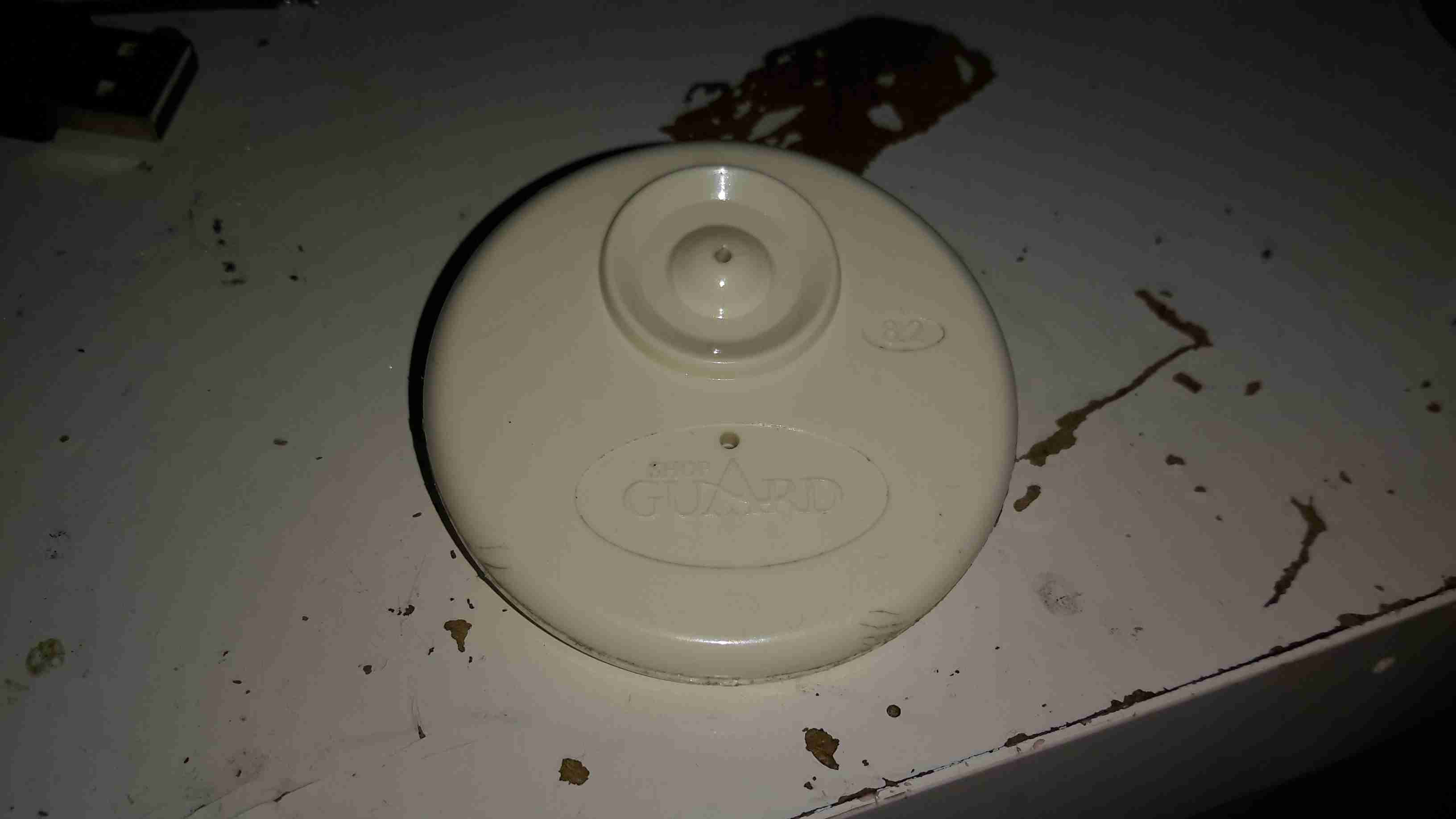
For a while I’ve wondered how these pancake type (AKA “Shaftless”) vibration motors operate, so I figured I’d mutilate one to find out.

Pancake Vibration Motor

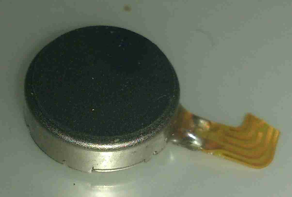
These vibrators are found in all kinds of mobile devices as a haptic feedback device, unlike older versions, which were just micro-sized DC motors with an offset weight attached to the shaft, these don’t have any visible moving parts.

Cover Removed
Cover Removed

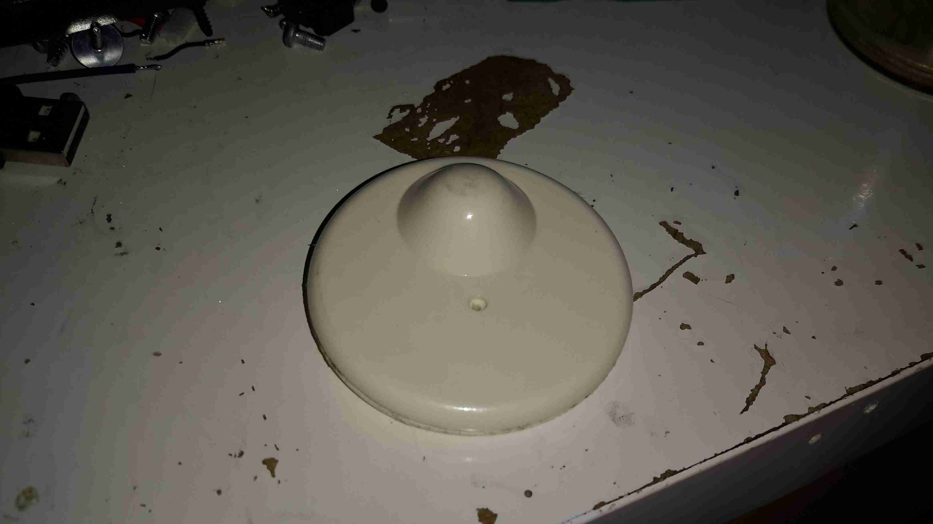
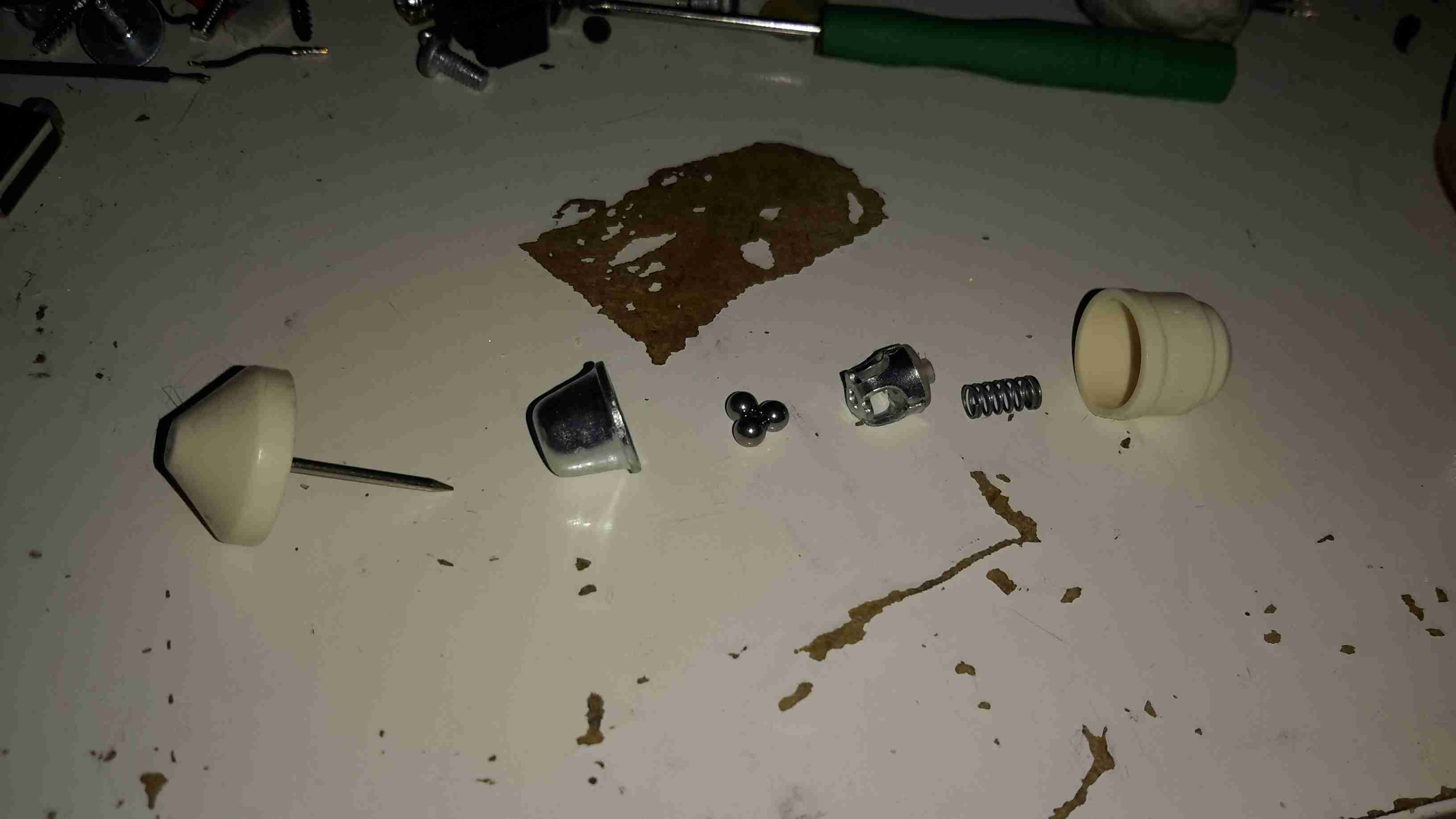
These devices are crimped together, so some gentle attack with a pair of snips was required to get the top cover off.
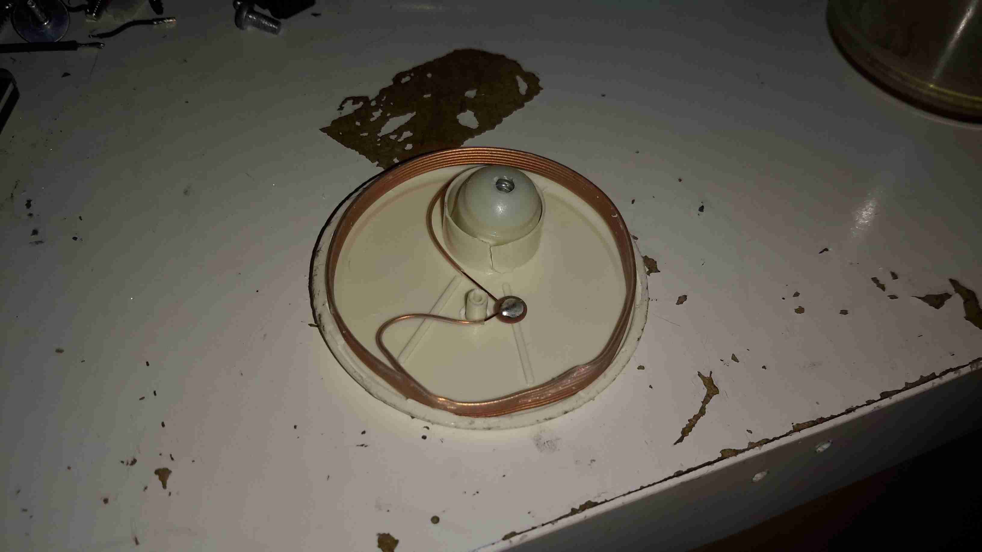
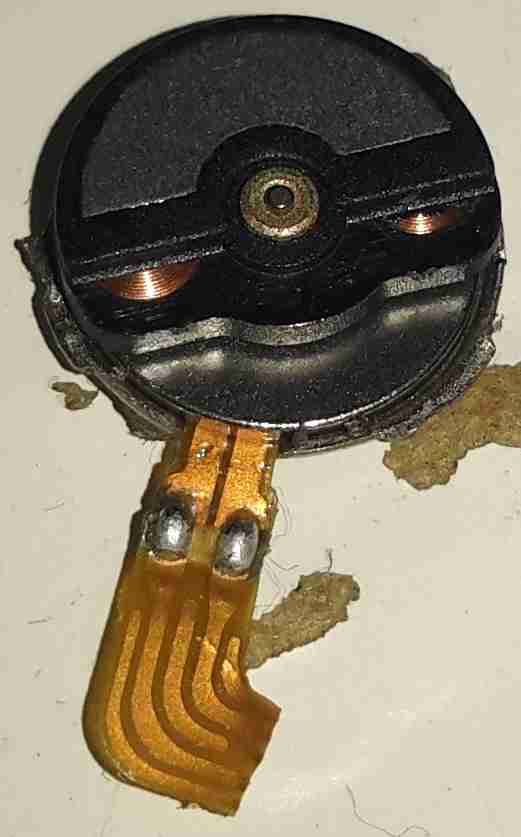
It turns out these are still a standard rotary DC motor, in this case specifically designed for the purpose. The rotor itself is the offset weight, just visible under the steel half-moon shaped section are the armature coils.

Weighted Rotor
Weighted Rotor

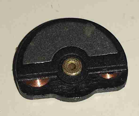
The armature lifts off the centre shaft, the coils can clearly be seen peeking out from under the counterweight.

Commutator
Commutator

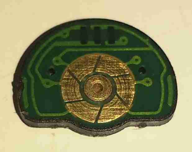
The underside of the armature reveals the commutator, which in this device is just etched onto the PCB substrate, the connections to the pair of coils can be seen either side of the commutator segments.

Brushes
Brushes

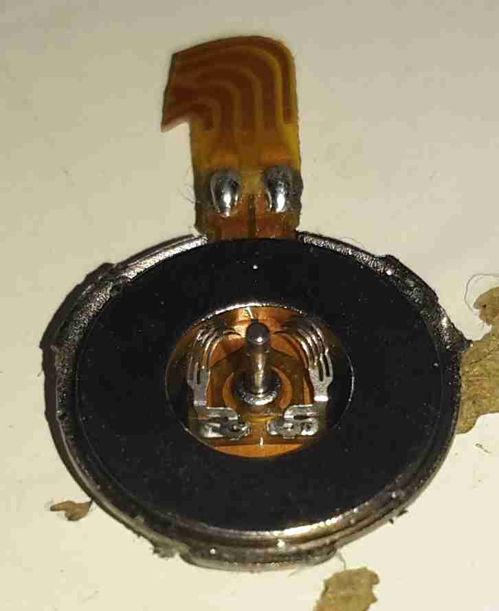
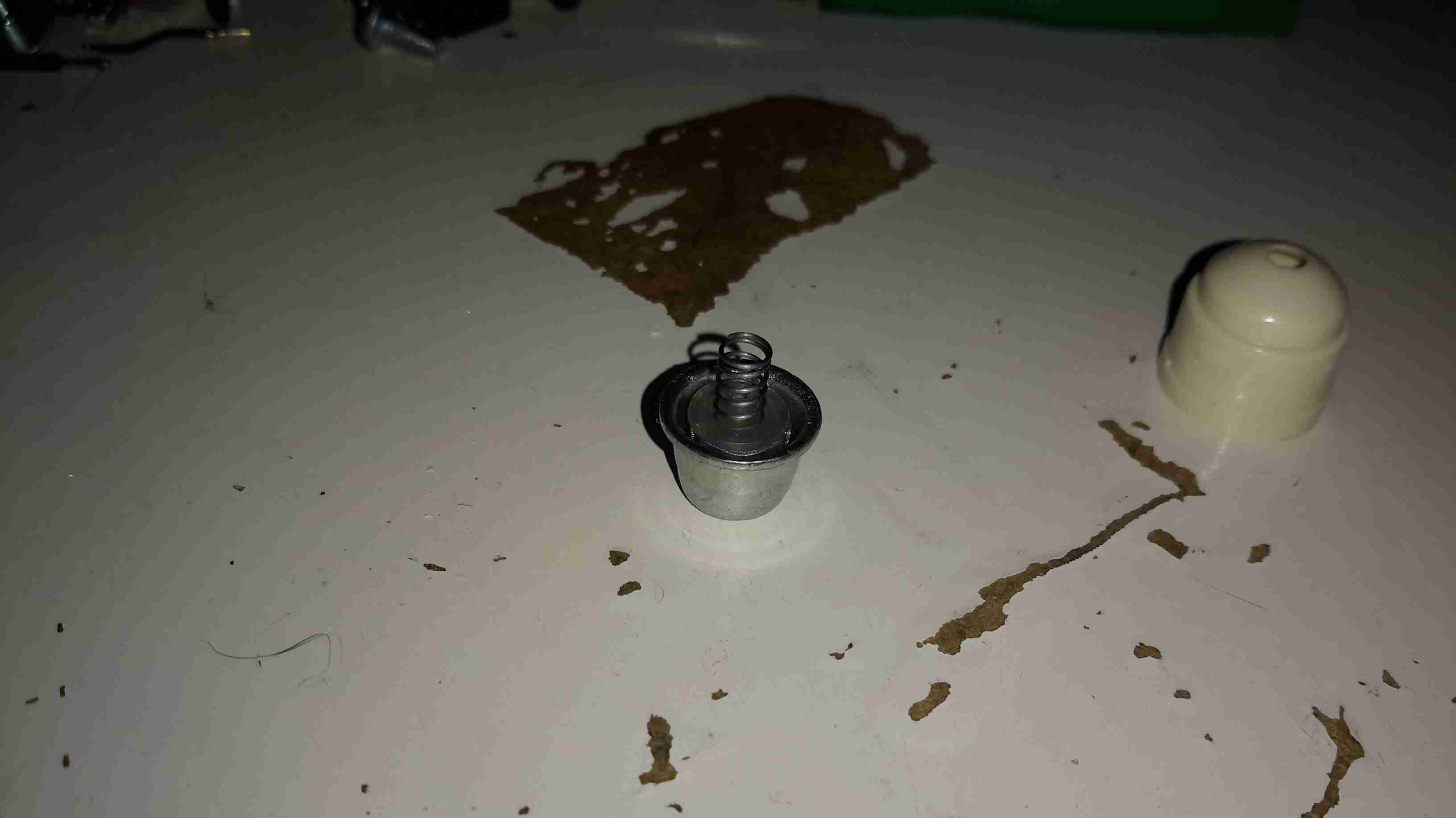
The base of the motor holds the brushes in the centre, the outer ring is the stationary permanent magnet. These brushes are absolutely tiny, the whole motor is no more than 6mm in diameter.

Posted on Leave a comment

Quickie Teardown – ShopGuard Anti-Theft Tag

ShopGuard Anti-Theft Tag

Everyone at some stage must have seen these EAS security tags in shops, usually attached to clothing with a steel pin. As some of this year’s presents had been left with the tags attached, I had to forcibly remove them before wrapping could commence.

Reverse Side
Reverse Side

These are just a plastic disc about 50mm in diameter, with an internal locking mechanism & RF tag inside.

RF Coil
RF Coil

After some careful attack with a saw around the glue seam, the tag comes apart into it’s halves. The RF coil & it’s ceramic capacitor can be seen wrapped around the outside of the tag. The capacitor in this case isn’t even epoxy dipped to save that extra 0.0001p on the manufacturing price. In the top centre is the pin locking mechanism, enclosed in a small plastic pill.

Lock Pill
Lock Pill

Popping off the back cap of the lock shows it’s internals.

Ball Bearing Lock Assembly

The lock itself is very simple. The centre section, held in place by a spring, carries 3 small ball bearings. The outer metal frame of the lock is conical in shape.

When the pin is pushed into the tag, the conical shape of the lock chamber causes the ball bearings to grab onto it, helped by the action of the spring that pushes the ball bearing carrier further into the cone.
This also means that any attempt to force the mechanism causes it to lock tighter onto the pin.
In normal operation, removal is achieved by a strong magnet that pulls the ball bearing carrier back slightly against it’s spring, allowing the pin to disengage & be pulled out.

This design is incredibly simple & cheap to make, and gains it’s locking strength from friction alone.

I would consider the RF coil being around the outer edge of the device a bit of a security risk – a quick chop with a sharp pair of wire cutters would disable the tag’s alarm functionality instantly. Making the coil slightly smaller & keeping it out of reach of the edge of the tag would help in this regard.

Posted on Leave a comment

ViewSonic VA2232W-LED Monitor 12v Conversion

ID Label
ID Label

On the quest to get things on board replaced that are heavy users of power, the monitor in the main cabin was next. The original CCFL-backlit monitor was very heavy on 12v power, at 5A. This meant falling asleep watching TV would result in severely flattened batteries.

Replacement with a suitable LED-backlit monitor was definitely required. The cheapest on eBay was a ViewSonic VA2232W-LED, so I took to work converting it from 240v to 12v operation.

Back Cover Removed
Back Cover Removed

There are no screws holding these monitors together, so a spudger & frequent swearing got the back off. The shield holding the circuitry is also not screwed down, only attached to the back of the LCD panel with aluminium shielding tape.

Power PCB Trackside
Power PCB Trackside

Once the tape has been cut, the main power board is accessible. The large IC on the left is the main backlight LED driver.

In this case the monitor requires a pair of rails from the supply, 18.5v for the backlight circuitry & 5v for the logic.

DC-DC Regulators
DC-DC Regulators

A pair of DC-DC converters has been fitted in the small space between the power & control boards.

PCB Connection Points

To save me some work & keep maximum compatibility, I’ve not modified the existing supply, just attached the new DC-DC converter outputs onto the corresponding outputs of the factory PSU. The 12v input leads are routed out of the same gap as the mains IEC connector, with some hot glue over the mains input solder points to provide some more insulation.

Wiring Tidied
Wiring Tidied

The wiring is tidied up with hot glue so the back cover will go back on.

Total current draw at 12v is 1.4A.

Posted on Leave a comment

Electronic Lighter – eBay Freebie

With a recent order from a Chinese seller on eBay, this little gadget was included in the package as a freebie:

Electronic Lighter
Electronic Lighter

I’ve not smoked for a long time, so I’m not too sure what use I’m going to find for this device, but it’s an electronic lighter!

Pyromaniac Mode
Pyromaniac Mode

Pushing the slider forward reveals a red-hot heater, mounted in the plastic (!) frame.

Charging Mode
Charging Mode

Pushing the other way reveals a USB port to charge the internal battery.

Core Removed
Core Removed

A couple of screws releases the end cap from the cover & the entire core unit slides out. Like all Chinese toys it’s made of the cheapest plastic imaginable, not such a good thing when heat is involved.

Heating Element
Heating Element

The element itself is a simple coil of Nichrome wire, crimped to a pair of brass terminals. The base the heater & it’s terminals are mounted to is actually ceramic – the surround though that this ceramic pill clips into is just the same cheap plastic. Luckily, the element only remains on for a few seconds on each button push, there’s no way to keep it on & start an in-pocket fire, as far as I can see.

Main PCB
Main PCB

The main PCB clips out of the back of the core frame, the large pair of tinned pads on the left connect to the heater, the control IC has no numbering of any kind, but considering the behaviour of the device it’s most likely a standard eCig control IC.

LiPo Cell
LiPo Cell

The other side of the board has the USB port on the right, the Lithium Polymer cell in the centre, and the power button on the left. The cell itself also has no marking, but I’m guessing a couple hundred mAh from the physical size.


Posted on Leave a comment

Cheap Lithium Polymer Battery Packs

In the past, I’ve used RC type LiPo packs for my mobile power requirements, but these tend to be a bit bulky, since they’re designed for very high discharge current capability – powering large motors in models is a heavy job.

I recently came across some Samsung Galaxy Tab 10.1 battery packs on eBay very cheaply, at £2.95 a piece. For this price I get 6800mAh of capacity at 4.2v, for my 12v requirements, 3 packs must be connected in series, for a total output of 12.6v fully charged.

For an initial pack, I got 9 of these units, to be connected in 3 sets of 3 to make 20Ah total capacity.There are no control electronics built into these batteries – it’s simply a pair of 3400mAh cells connected in parallel through internal polyfuses, and an ID EEPROM for the Tab to identify the battery.
This means I can just bring the cell connections together with the original PCB, without having to mess with the welded cell tabs.

Battery Pack
Battery Pack

Here’s the pack with it’s cell connections finished & a lithium BCM connected. This chemistry requires close control of voltages to remain stable, and with a pack this large, a thermal runaway would be catastrophic.

Cell Links
Cell Links

The OEM battery connector has been removed, and my series-parallel cell connections are soldered on, with extra lead-outs for balancing the pack. This was the most time-consuming part of the build.

If all goes well with the life of this pack for utility use, I’ll be building another 5 of these, for a total capacity of 120Ah. This will be extremely useful for portable use, as the weight is about half that of an equivalent lead-acid.

Posted on Leave a comment

LB-Link USB Wireless-N Adaptor Teardown

I needed a decent WiFi adaptor for my latest Pi LCD project, so after trawling eBay for cheapy USB adaptors, I found this one.

USB WiFi Dongle
USB WiFi Dongle

Unlike most USB WiFi radios these days, it actually has a proper RP-SMA antenna connector, not the low-gain built in jobbies that never seem to work too well.
There are a few versions of this adaptor, all of which seem to use the same casing, there’s a button push cut into the plastic for a WPS button that doesn’t exist on this model. This is fine, as I don’t enable WPS on any of my network equipment anyway. (It’s insecure, and can be cracked in minutes).

MAC Address
MAC Address

Here’s the rest of the essential details, the model is BL-LW08-AR, rated at 300Mbit/s.

PCB Reverse
PCB Reverse

Here’s the PCB removed from the casing, there are a pair of PCB antennas on here, but they’re not connected to the RF circuitry in this model, the links are missing.

Chipset
Chipset

The chipset used is a Realtek RTL8191SU, there isn’t much more in this device, as it’s all built into the silicon.


Posted on 3 Comments

Fire Angel CO-9D Carbon Monoxide Detector Teardown

Fire Angel CO-9D CO Detector

This detector has now been retired from service since it’s a fair bit out of date. So here’s the teardown!

Information
Information

Unlike older detectors, this unit has a built in battery that never needs replacing during the life of the sensor, so once the unit reaches it’s expiry date it’s just trashed as a whole.

Cover Removed
Cover Removed

4 screws hold the cover on, here’s the internals of the detector. There’s a 3v CR123A LiMnO² cell at the right for power, rated at 1500mAh. A 7 year life is quite remarkable on a single cell!
The sensor is just to the left of the lithium cell, and is of quite unusual construction. Previous CO sensor cells I’ve seen have been small cylinders with a pair of brass pins. This one appears to use a conductive plastic as the connections. These sensors contain H²SO⁴ so they’re a bit hazardous to open.
There are no manufacturer markings on the sensor & I’ve not been able to find any similarly shaped devices, so I’m unsure of it’s specifications.
The alarm sounder is on the left, the usual Piezo disc with a resonator to increase the loudness.

Microcontroller
Microcontroller

The brains of the device are provided by a Microchip PIC16F914 microcontroller. This is a fairly advanced device, with many onboard features, and NanoWatt™ technology, standby power consumption is <100nA according to Microchip’s Datasheet. This would explain the incredible battery life.
The choke just at the right edge of the photo is actually a transformer to drive the Piezo sounder at high voltage.

PCB Reverse
PCB Reverse

Here’s the PCB with the LCD frame removed. Not much to see on the this side, the silence/test button top right & the front end for the sensor.

Sensor Front End Amplifier

Here’s a closer look at the front end for the CO sensor cell itself. I haven’t been able to decode the SMT markings on the SOT packages, but I’m guessing that there’s a pair of OpAmps & a voltage reference.