Posted on Leave a comment

Dear Chester

As many will already know, we lost a guiding light in the Rock World last week, Chester Bennington of Linkin Park. I am reposting the message from the other bandmembers here, being one of the first bands I ever listened to of this genre. As someone with mental illness, seeing someone identify their depression, and having it still kill them is rather disturbing.

RIP Chester, Forever With Us In Song


Dear Chester,

Our hearts are broken. The shockwaves of grief and denial are still sweeping through our family as we come to grips with what has happened.

You touched so many lives, maybe even more than you realized. In the past few days, we’ve seen an outpouring of love and support, both public and private, from around the world. Talinda and the family appreciate it, and want the world to know that you were the best husband, son, and father; the family will never be whole without you.

Talking with you about the years ahead together, your excitement was infectious. Your absence leaves a void that can never be filled—a boisterous, funny, ambitious, creative, kind, generous voice in the room is missing. We’re trying to remind ourselves that the demons who took you away from us were always part of the deal. After all, it was the way you sang about those demons that made everyone fall in love with you in the first place. You fearlessly put them on display, and in doing so, brought us together and taught us to be more human. You had the biggest heart, and managed to wear it on your sleeve.

Our love for making and performing music is inextinguishable. While we don’t know what path our future may take, we know that each of our lives was made better by you. Thank you for that gift. We love you, and miss you so much.

Until we see you again,

LP


Posted on Leave a comment

Virtualmin Mail – Enabling Sieve Support

For years now I’ve used Virtualmin for my hosting requirements, and have made use of Procmail to filter my mail into folders (it’s the default, and rather tightly integrated). The only issue with this system is having to login to two different things for mail: I use Rainloop Webmail for general mail viewing, but the Procmail filters are only editable through the Usermin section of Virtualmin. This is awkward to say the least, so being able to use Sieve which is already supported by Rainloop is a better option. (Sieve is also supported via plugin in Roundcube).

Since we’re going to still need Procmail for the Virtualmin-managed Spam & Virus scanning functions, we will add Sieve at the end of Procmail. There are some

First thing, get Sieve installed via Dovecot, with the following:

yum install dovecot-pigeonhole

Some configuration changes are required to Dovecot to get the Sieve server running, /etc/dovecot/conf.d/15-lda.conf should have this section:

protocol lda {
 # Space separated list of plugins to load (default is global mail_plugins).
 mail_plugins = sieve
}

Finally, in /etc/dovecot/conf.d/20-managesieve.conf, uncomment this section to enable the managesieve server:

service managesieve-login {
 inet_listener sieve {
 port = 4190
 }
}

After these changes are made, restart Dovecot to get the configs reloaded. It’s easy to check if the Sieve server is listening by running the following command:

lsof -i:4190
COMMAND PID USER FD TYPE DEVICE SIZE/OFF NODE NAME
dovecot 58667 root 15u IPv4 34795427 0t0 TCP *:sieve (LISTEN)
dovecot 58667 root 16u IPv6 34795428 0t0 TCP *:sieve (LISTEN)

Now for some minor changes to /etc/procmailrc to direct mail to Dovecot for delivery:

LOGFILE=/var/log/procmail.log
TRAP=/etc/webmin/virtual-server/procmail-logger.pl
:0wi
VIRTUALMIN=|/etc/webmin/virtual-server/lookup-domain.pl --exitcode 73 $LOGNAME
EXITCODE=$?
:0
* ?/bin/test "$EXITCODE" = "73"
/dev/null
EXITCODE=0
:0
* ?/bin/test "$VIRTUALMIN" != ""
{
INCLUDERC=/etc/webmin/virtual-server/procmail/$VIRTUALMIN
}
DEFAULT=$HOME/Maildir/
ORGMAIL=$HOME/Maildir/
DROPPRIVS=yes
:0 w
|/usr/libexec/dovecot/deliver
$DEFAULT

I personally got an error when I made all these changes, which in my case was a permissions issue on the Dovecot log:

Can't open log file /var/log/dovecot: Permission denied
procmail: Program failure (75) of "/usr/libexec/dovecot/deliver"

This was solved by opening the permissions for /var/log/dovecot, this then vanished, and the logs confirmed Sieve was working properly.

Posted on Leave a comment

Tenda S105 5-Port 10/100 Ethernet Switch

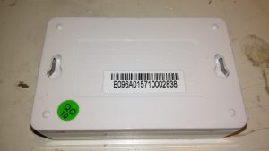
Top
Top

Here’s a tiny ethernet switch from the great fle market that is eBay – the Tenda S105. This unit has 5 ports, but only supports 10/100M. Still, for something so small it’s not bad.

Bottom
Bottom

Not much on the bottom, there’s a pair of screw hooks for mounting this to a surface.

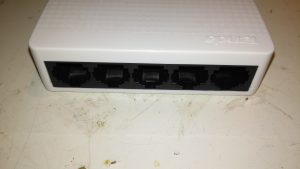
Ports
Ports

The 5 ports on the front actually have the pins for the unused pairs of the ethernet cables removed – saving every penny here.

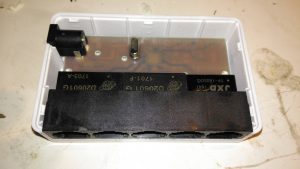
PCB Top
PCB Top

The casing just unclips, revealing the small PCB. Nothing much on the top, just the connectors, isolating transformers & the crystal for the switch IC.

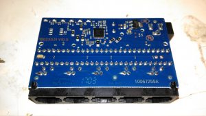
PCB Bottom
PCB Bottom

The bottom of the PCB is a little more busy, mainly with decoupling components. There’s a 3.3v linear regulator to step down the 5v input for the switch IC.

Switch IC
Switch IC

The IC doing all the data switching is an IP175G 5-Port 10/100 Switch from IC+ Corp. No datasheet available for this, but it’s going to be a bog-standard switch.

Posted on 2 Comments

PowerAdd Pilot X7 20,000mAh Powerbank & Fast Charging Mod

PowerAdd Pilot X7
PowerAdd Pilot X7

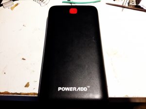
Here’s the biggest portable USB powerbank I’ve seen yet – the PowerAdd Pilot X7, this comes with a 20Ah (20,000mAh) capacity. This pack is pretty heavy, but this isn’t surprising considering the capacity.

USB Ports & LED
USB Ports & LED

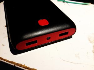
The front of the pack houses the usual USB ports, in this case rated at 3.4A total between the ports. There’s a white LED in the centre as a small torch, activated by double-clicking the button. A single click of the button lights up the 4 blue LEDs under the housing that indicate remaining battery capacity. Factory charging is via a standard µUSB connector in the side, at a maximum of 2A.

PCB Front
PCB Front

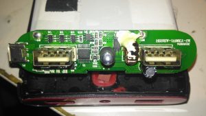
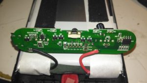
The front of the PCB holds the USB ports, along with most of the main control circuitry. At top left is a string of FS8025A dual-MOSFETs all in parallel for a current carrying capacity of 15A total, to the right of these is the ubiquitous DW01 Lithium-Ion protection IC. These 4 components make up the battery protection – stopping both an overcharge & overdischarge. The larger IC below is an EG1501 multi-purpose power controller.

This chip is doing all of the heavy lifting in this power pack, dealing with all the DC-DC conversion for the USB ports, charge control of the battery pack, controlling the battery level indicator LEDs & controlling the torch LED in the centre.

EG1501 Example
EG1501 Example

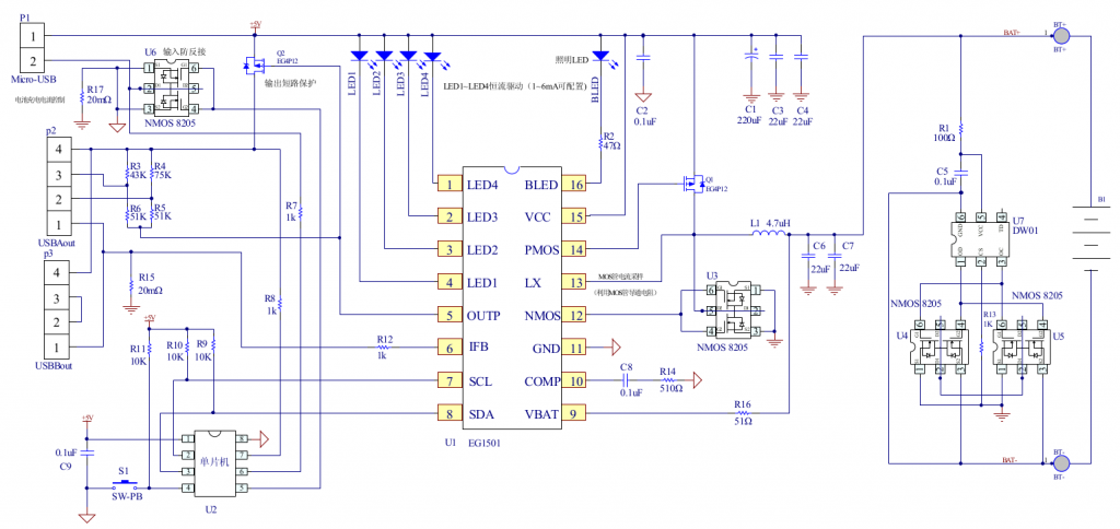
The datasheet is in Chinese, but it does have an example application circuit, which is very similar to the circuitry used in this powerbank. A toroidal inductor is nestled next to the right-hand USB port for the DC-DC converter, and the remaining IC next to it is a CW3004 Dual-Channel USB Charging Controller, which automatically sets the data pins on the USB ports to the correct levels to ensure high-current charging of the devices plugged in. This IC replaces the resistors R3-R6 in the schematic above.
The DC-DC converter section of the power chain is designed with high efficiency in mind, not using any diodes, but synchronous rectification instead.

PCB Back
PCB Back

The back of the PCB just has a few discrete transistors, the user interface button, and a small SO8 IC with no markings at all. I’m going to assume this is a generic microcontroller, (U2 in the schematic) & is just there to interface the user button to the power controller via I²C.

Cells
Cells

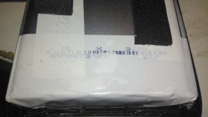
Not many markings on the cells indicating their capacity, but a full discharge test at 4A gave me a resulting capacity of 21Ah – slightly above the nameplate rating. There are two cells in here in parallel, ~10Ah capacity each.

XT60 Battery Connector

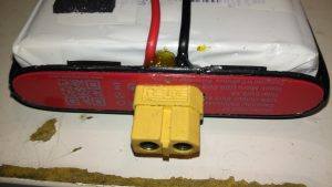
The only issue with powerbanks this large is the amount of time they require to recharge themselves – at this unit’s maximum of 2A through the µUSB port, it’s about 22 hours! Here I’ve fitted an XT60 connector, to interface to my Turnigy Accucell 6 charger, increasing the charging current capacity to 6A, and reducing the full-charge time to 7 hours. This splits to 3A charge per cell, and after some testing the cells don’t seem to mind this higher charging current.

Battery Connector Wiring

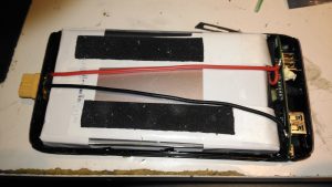
The new charging connector is directly connected to the battery at the control PCB, there’s just enough room to get a pair of wires down the casing over the cells.

Posted on Leave a comment

Anker PowerPort Speed 5 12v DC Conversion

A few months ago I did a teardown on this Anker PowerPort Speed 5 USB charger, but I didn’t get round to detailing the conversion to 12v I had to do, so I’ll get to that now I’ve got a couple more to convert over.

Power Module
Power Module

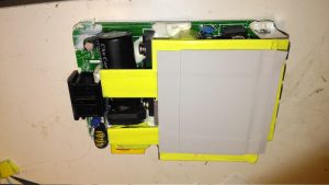
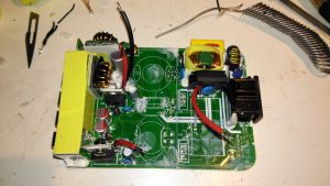
Here’s the internals of the Anker charger once I’ve removed the casing – which like many things these days, is glued together. (Joints can be cracked with a screwdriver handle without damaging the case). There’s lots of heatsinking in here to cool the primary side switching devices & the pot core transformers, so this is the first thing to get removed.

Heatsink Removed
Heatsink Removed

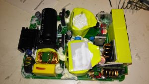
Once the heatsink has been removed, the pot core transformers are visible, wrapped in yellow tape. There’s some more heatsink pads & thermal grease here, to conduct heat better. The transformers, primary side switching components & input filter capacitor have to go.

Primary Side Components Removed

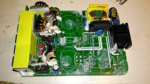
Here’s the PCB once all the now redundant mains conversion components have been deleted. I’ve left the input filtering & bridge rectifier in place, as this solves the issue of the figure-8 cable on the input being reversible, polarity of the input doesn’t matter with the bridge. I’ve removed the main filter capacitor to make enough room for the DC-DC converters to be fitted.

Tails Installed
Tails Installed

Installing the tails to connect everything together is the next step, this charger requires two power supplies – the QC3 circuits need 14.4v to supply the multi-voltage modules, the remaining 3 standard ports require 5v. The DC input tails are soldered into place where the main filter capacitor was, while the outputs are fitted to the spot the transformer secondary windings ended up. I’ve left the factory Schottky rectifiers in place on the secondary side to make things a little more simple, the output voltages of both the DC-DC converters does need to be increased slightly to compensate for the diode drops though. I’ve also bypassed the mains input fuse, as at 12v the input current is going to be substantially higher than when used on mains voltage.

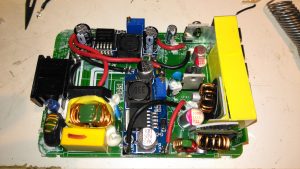
DC-DC Converters Installed

With a squeeze both the boost converter & the buck converter fit into place on the PCB.

Posted on Leave a comment

nb Tanya Louise – Gas Locker Corrosion Part 1 – Removing The Old Locker & Replacing the Deck Plate

Severe Corrosion
Severe Corrosion

This is a part of the boat that hasn’t really had much TLC since we moved aboard, and finally it’s completely succumbed to corrosion, opening a rusty hole into the engine space below. I’ve already used a grinder to remove the rest of the locker – and even this had corroded to the point of failure all around the bottom just above the welds. The bulkhead forming the rear of the locker has also corroded fairly severely, so this will be getting cut out & replaced with a new piece of steel.
This was originally a 1/8″ plate, but now it’s as thin as foil in some places, with just the paint hiding the holes.

Replacement Steel
Replacement Steel

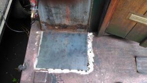
I’ve cut out as much of the corroded deck plate as possible –  it’s supported underneath by many struts made of angle iron, and got the new 3mm replacement tacked in place with the MIG. I’ve not yet cut out the rotten section on the bulkhead, this will come after we’ve got the steel cut to replace it, as electrical distribution is behind this plate – I’d rather not have weather exposure to the electrical systems for long! Unfortunately more corrosion has showed itself around the edges of the old locker:

Thin Steel
Thin Steel

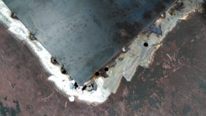
Around the corner the steel has pretty much totally failed from corrosion coming from underneath – applying welding heat here has simply blown large holes in the steel as there’s nothing more than foil thickness to support anything.

Some more extensive deck replacement is going to happen to fix this issue, more to come when the steel comes in!