Posted on Leave a comment

nb Tanya Louise Hydraulic Generator

Hydraulic Generator Unit

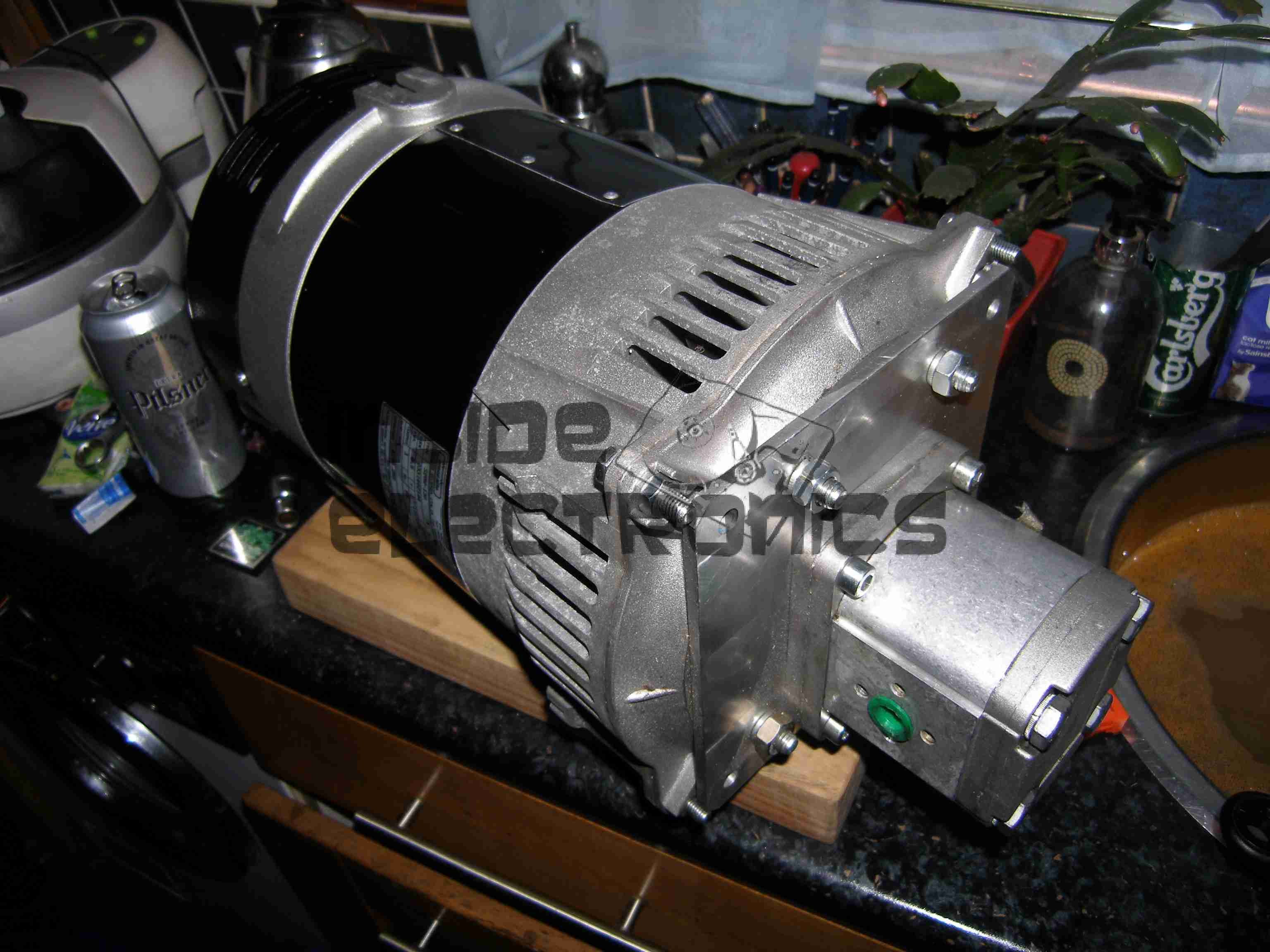
To accompany the previous two posts about hydraulic generators & their components, here is the actual generator unit itself.

Rated at 8.5kVa 230v AC, this will providea mains supply while the narrowboat is away from her home mooring.

This unit will be attached to the side of the hull in the engine room on rubber vibration isolation mounts, behind the main hydraulic oil tank & is driven from the small gear pump attached to the back of the main propulsion hydraulic pump unit.
Operating pressure is 175 bar, 21L/m flow rate to achieve the 3,000RPM rotor speed for 50Hz mains frequency.

Generator Specifications
Posted on Leave a comment

Datakom DKG-171

Front
Front

Here is a teardown of the Datakom DKG-171 generator transfer controller. Here is the front of the unit, with the pictogram of the system, the indicator LEDs & the generator test button.


Rear
Rear

The rear of the unit features the connection points for the mains, generator & generator control I/O.

PCB Rear
PCB Rear

Rear of the PCB with the control relays. The two larger relays switch in the remote contactors to switch the mains supply over between the grid & the generator, while the smaller relay switches 12v power out to a terminal to automatically start the generator.

PCB Front
PCB Front

Front of the PCB with the control logic & main PIC microcontroller.


Posted on Leave a comment

Tool-less UK Mains Plug

Plug Bottom
Plug Bottom

This is a standard 13A UK main power plug – with a twist. This one requires no tools to open or connect.
The top cover is slid off the top, after turning the red cam with a coin to unlock it.

Plug Top
Plug Top

Manufactured by Plugco – a Google search of this company returns no results.

Cover Removed
Cover Removed

Top cover removed from the plug, as is standard with UK mains plugs the live conductor is fused – 3A in this case. The conductors are clamped into the fittings in a row along the top edge of the plug.

Wire Clamps
Wire Clamps

Closeup of the wire clamps. Conductor is placed in the slot & snapped closed.

This is an old plug & they do not appear to be available these days, for unknown reasons. Being able to change a plug without a screwdriver has it’s advantages 🙂

Posted on Leave a comment

Portable Power Pack Charger

A quick update to my portable power pack, a mains charging port. Uses a universal DC barrel jack.

Connection to the battery. 1N4001 reverse protection diode under the blue heatshrink tubing. I used a surplus PC CD-ROM audio cable (grey lead). Seen here snaking behind the battery to the DC In Jack.

Posted on Leave a comment

Dremel MultiPro

Front
Front

Here we have a Dremel MultiPro rotary tool, a main powered 125W 33,000RPM bit of kit.

Motor Assembly
Motor Assembly

Here the field & controller assembly is removed from the casing.

Armature
Armature

Here is the armature, which rotates at up to 33,000RPM. The brushes rise against the commutator on the left, next to the bearing, the cooling fan is on the right hand side on the power output shaft, the chuck attaches at the far right end of the shaft.

Speed Controller & Brush Box

Here is the speed controller unit, inside is an SCR phase angle speed controller, to vary the speed of the motor from 10,000RPM to the full rated speed of 33,000RPM.

Mains Filter
Mains Filter

This is the mains filter on the input to the unit, stops stray RF from the motor being radiated down the mains cable.

Posted on Leave a comment

Hair Dryer

Housing
Housing

This is a 1500W hairdryer, death caused by thermal switch failure.

Switch
Switch

This is the switch unit. Attached are two suppression capacitors & a blocking diode. Cold switch is on right.

Heating Element
Heating Element

Heating element unit removed from housing. Coils of Nichrome wire heat the air passing through the dryer. Fan unit is on right.

Thermal Switch
Thermal Switch

Other side of the heating element unit, here can be seen the thermal switch behind the element winding. (Black square object).

Fan Motor
Fan Motor

The fan motor in this dryer is a low voltage DC unit, powered through a resistor formed by part of the heating element to drop the voltage to around 12-24v. Mounted on the back of the motor here is a rectifier assembly. Guide vanes are visible around the motor, to straighten the airflow from the fan blades.

Fan
Fan

5-blade fan forces air through the element at high speed. Designed to rotate at around 13,000RPM.