Posted on 4 Comments

Audi TT Roof Hydraulics

Pump
Pump

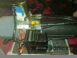
This is the hydraulic system from an Audi TT that would power the soft top. Here is the hydraulic pump unit. Oil Tank is on the left. Power is 12v DC at ~20A
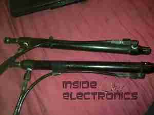
Cylinders
Cylinders

The pair of hydraulic cylinders that attached to the roof mechanism.
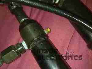
Limit Switch
Limit Switch

One of the cylinders has a limit switch built in. The brass bolt coming out of the side of the head is one contact. The other contact is the cylinder body.
Hose
Hose

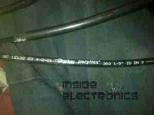
Marking on the hoses. This is Parker Polyflex hydraulic hose. 1/8″ ID.
Motor
Motor

Drive motor for the hydraulic pump. Standard DC permanent magnet motor.
Motor Suppression
Motor Suppression

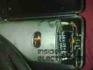
Motor power terminals & suppression capacitors. As the reversing relays actually short the motor out when de-energized, there is a lot of arcing at the brushes without some suppression.
Reversing Relays
Reversing Relays

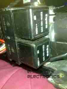
Reversing relay stack. Each relay is a SPDT configuration. The pair are arranged as a DPDT bank to reverse the motor, depending on which relay is energized.
Tank
Tank

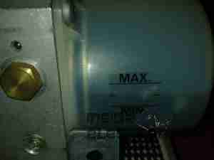
Detail of the oil tank showing the level markings.
Power Valve
Power Valve

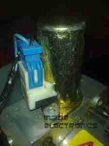
Solenoid valve on top of the unit. This valve provides full pump pressure to the cylinders when energized.
Posted on Leave a comment

Power Pack Regulator Update

7.5v Regulator
7.5v Regulator

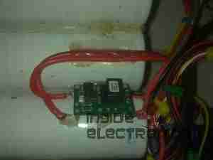
To help make my system more efficient, a pair of switching regulators has been fitted, the one shown above is a Texas Instruments PTN78060 switchmode regulator module, which provides a 7.5v rail from the main 12v battery pack.

A Lot like the LM317 & similar linear regulators, these modules require a single program resistor to set the output voltage, but are much more efficient, around the 94% mark at the settings used here.

The 7.5v rail supplies the LM317 constant current circuit in the laser diode driver subsection. This increases efficiency by taking some voltage drop away from the LM317.

5v Regulator
5v Regulator

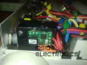
The 7.5v rail also provides power to this Texas Instruments  PTH08000 switchmode regulator module, providing the 5v rail for the USB port power.

Posted on Leave a comment

Logitech Cordless Ball Mouse

Top
Top

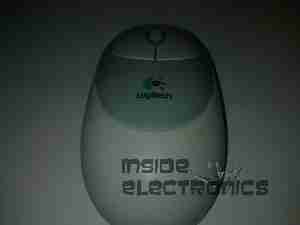
This is an old legacy wireless mouse from Logitech. This uses a ball rather than optical technology.

Bottom
Bottom

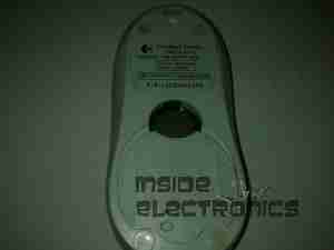
Bottom of the mouse, showing the battery cover & the mouse ball.

PCB Bottom
PCB Bottom

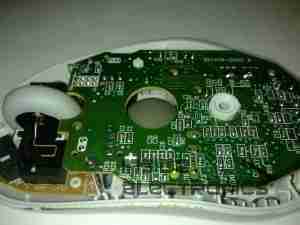
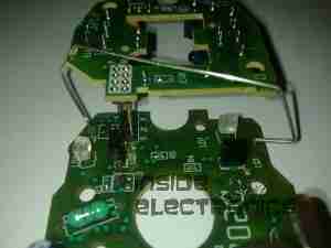
Top removed from the mouse, showing the PCB inside. The smaller PCB on the left supports the microswitches for the buttons & mouse wheel.

Switches
Switches

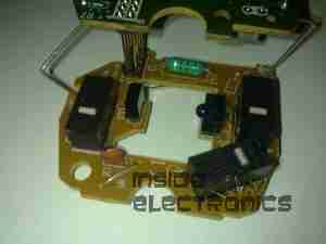
Closeup of small PCB showing the microswitches & the IR LED & phototransistor pair for the mouse wheel encoder.

Main PCB
Main PCB

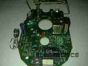
View of main PCB, with interface IC lower right. Pair of quartz crystals provide clocking for the transmitter & internal µC.
Battery contacts are on lower left of the PCB. At the top are the IR pairs for the X & Y axis of the mouse ball.

Encoder Pairs
Encoder Pairs

Closeup of the pairs of IR LEDs & phototransistors that make up the encoders for X/Y movement of the mouse, together with the slotted wheels in the mouse base that rotate with the ball. Steel wire around the smaller PCB is the antenna.

Posted on Leave a comment

Belkin PCMCIA Wi-Fi Card

Top label
Top label

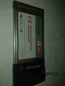
Here is an old Belkin Wireless G network card. This is a PCMCIA version.

Bottom Label
Bottom Label

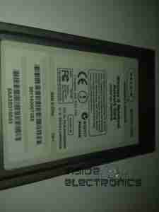
Here is the bottom of the device, with all the details.

Antenna
Antenna

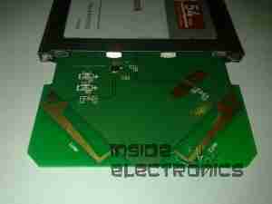
Plastic antenna cover removed, showing the pair of 2.4GHz etched antennae. There is a pair of LEDs on the upper left of the PCB showing activity & link status.

PCB
PCB

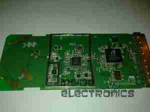
Overall view of the PCB, antennae on the left, RF chipset in centre, WiFi controller IC on right, and PCMCIA socket on far right. Can below wireless controller is a quartz crystal for the clock.

Chipset
Chipset

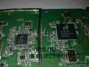
Closeup of the chipset, a Ralink RT2560F wireless controller on the right & a RT2525L transceiver on the left.