Posted on Leave a comment

nbTanya Louise Generator Transfer Controller

Contactor Box
Contactor Box

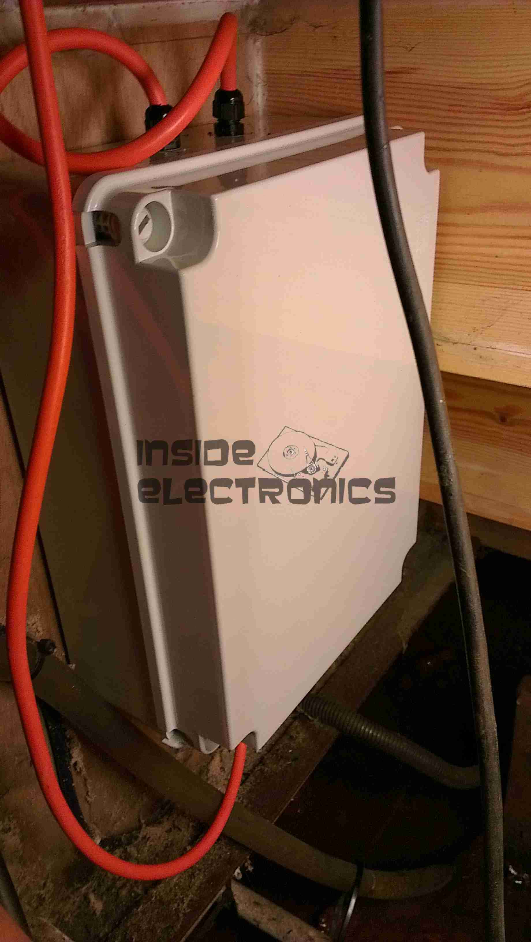
Here is the latest build & addition to the boat, in preparation for delivery of an 8kVa hydraulically driven generator unit – an automatic transfer switch.
Above can be seen the completed contactor unit, mounted in the engine bay.
This unit takes feeders from both the shore power socket & the generator unit & switches them independently through to the domestic 240v AC systems on board.

Contactor switching is done by a Datakom DKG-171 automatic generator controller.

Switching Unit
Switching Unit

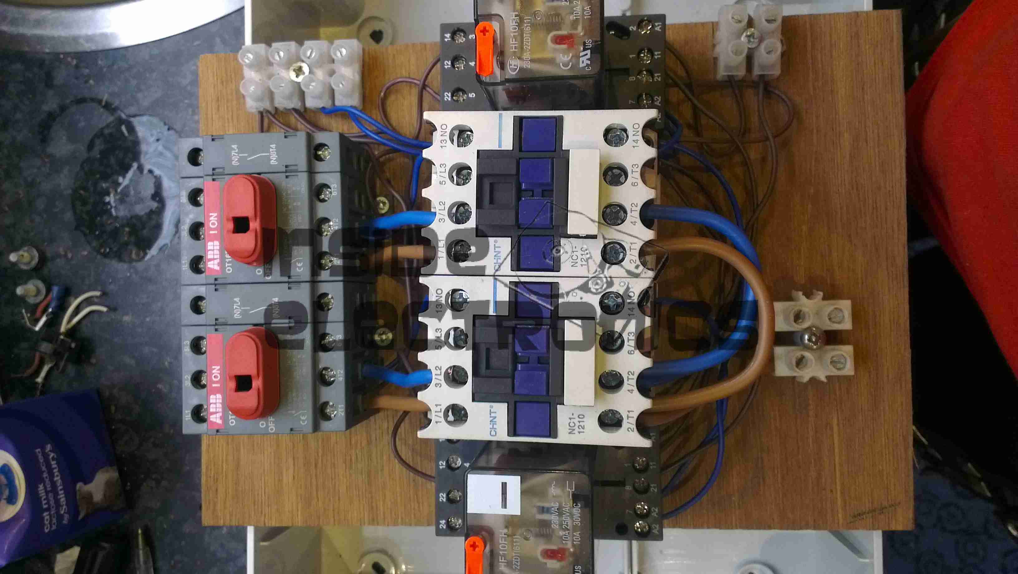
Here are the contactors & isolators, before fitting to the wallbox. Power comes in one the left, through the large 25A isolating switches, before feeding to a pair of 30A contactors. The pair of outer relays next to the contactors are interlocks. These ensure that when one contactor is energized, the other is electrically locked out. Even if the interlock relay is manually operated with the orange flag visible on the top of the unit, they are wired to de-energize both contactors. This ensures that under no circumstances can both power sources be connected at the same time.

Panel Cutout
Panel Cutout

The generator controller requires a 68mmx68mm panel cutout for mounting. This was done in the main panel next to the electrical locker.

Box Fitted
Box Fitted

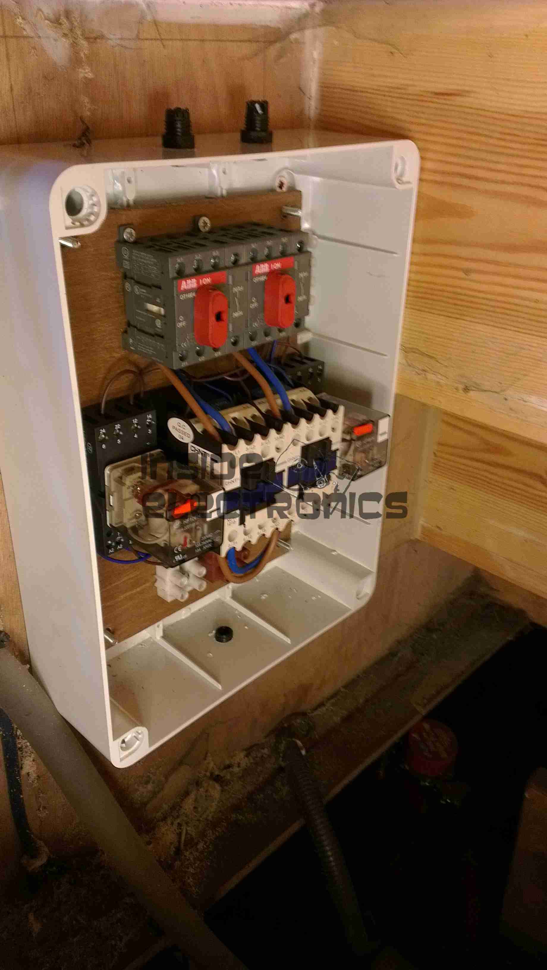
Here the contactor board has been fitted into the wallbox & the cable glands fitted before wiring.

DKG-171
DKG-171
System Online
System Online

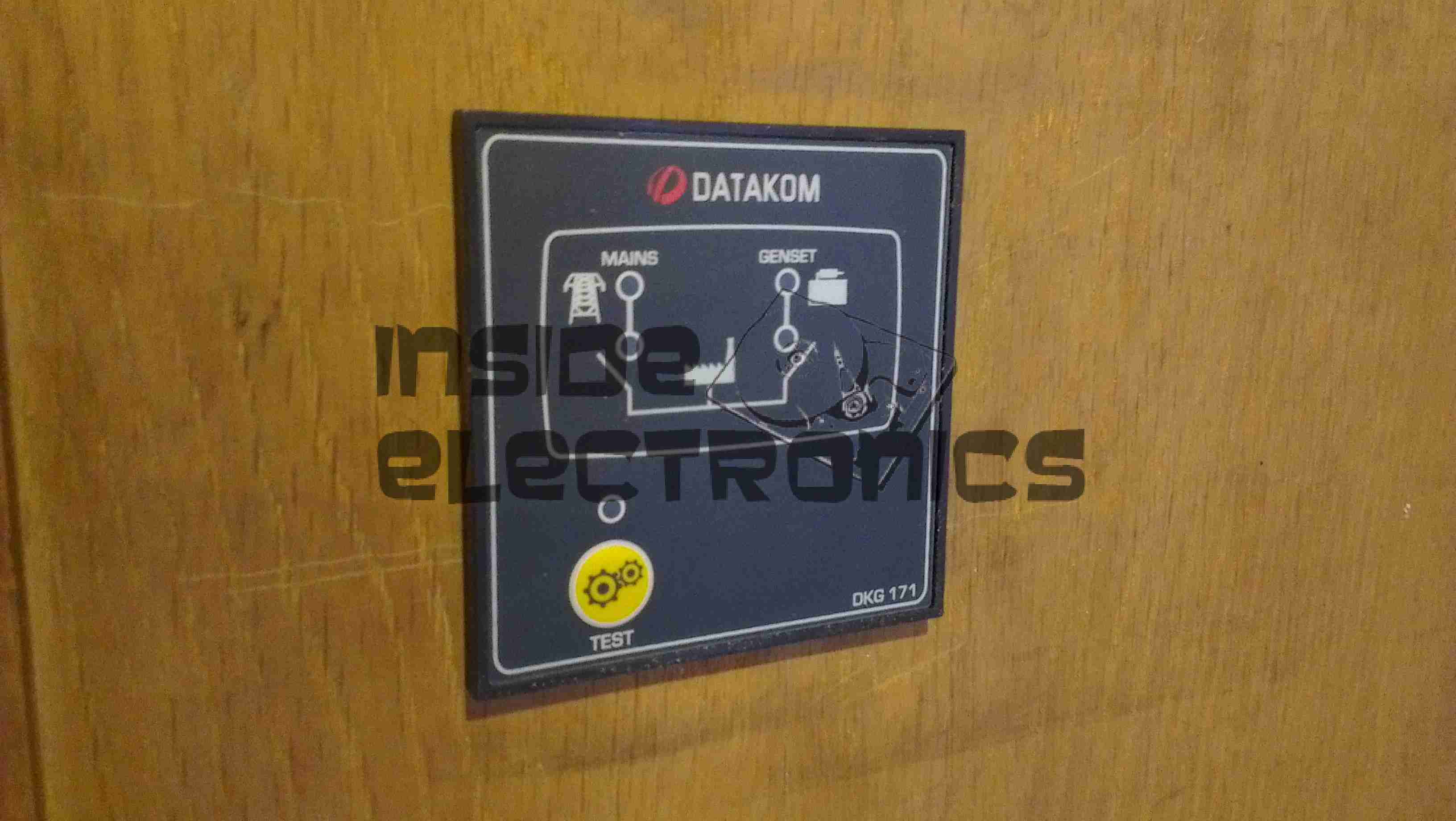
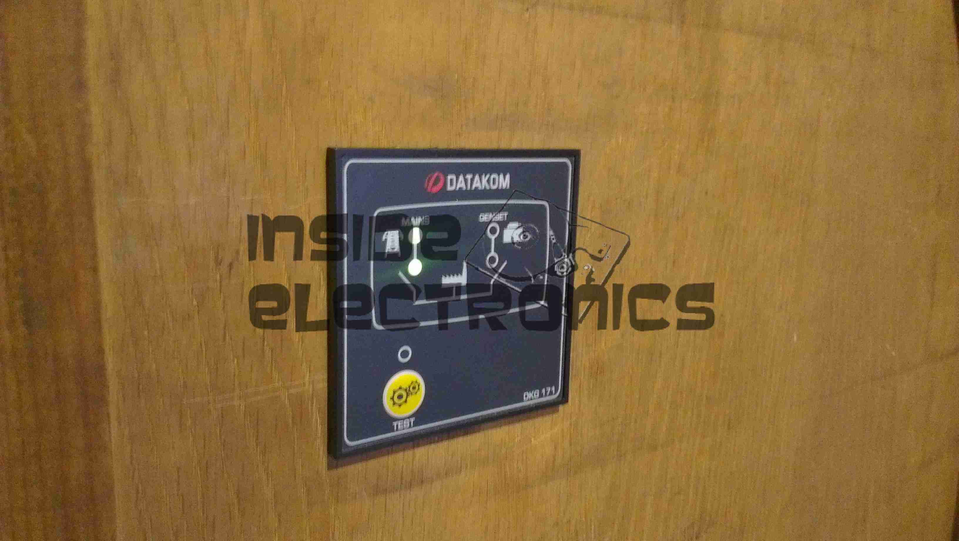
The generator controller fitted & finally energized. The indicator LEDs on the front of the unit let the user know where power is currently being supplied from & which contactor is energized.


Posted on Leave a comment

Pringles Speaker Modifications

USB Charging Port
USB Charging Port

These speakers are available free from Pringles, with two packs bought. Normally running on 3x AAA cells, I have made modifications to include a high capacity Li-Ion battery & USB charging.

18650 Battery
18650 Battery

New battery is 3x 18650 Li-Ion cells in parallel, providing ~6600mAh of capacity. These are hot glued inside the top of the tube under the speaker, with the charging & cell protection logic.
The battery charging logic is salvaged from an old USB eCig charger, these are single cell lithium chargers in a small form factor ideal for other uses. Charging current is ~450mA.

Amplifier Board
Amplifier Board

The cells are connected to the same points as the original AAA cells, with the other pair of wires going into the top of the device to connect to the MicroUSB charging port.

The amplifier in this is a LM4871 3W Mono amplifier IC, connected to a 6Ω 1W speaker.
The other IC on the board is unidentifiable, but provides the flashing LED function to the beat of the music.


Posted on Leave a comment

Mobile Power Pack Upgrade

New Regulators
New Regulators

The original LM2577 based regulators I designed into my mobile battery pack turned out to be insufficient for requirements, therefore they have been replaced with higher capacity regulators.

The 12v regulator (left) is a muRata UQQ-12/8-Q12P-C SEPIC converter, providing a max of 8A at 12.1v DC. The 12v rail is also now independently switchable to save power when not in use.

The 5v regulator (right) is a Texas Instruments PTN78020WAZ switching regulator, rated at 6A. The pair of resistors on the back of the regulator set the output voltage to 5.1v.

Also a new addition is a pair of banana sockets & a 2.1mm DC jack, wired into the 12v DC bus, for powering various accessories.

New Additions
New Additions

Below the USB sockets is now a built in eCig charger, to save on USB ports while charging these devices.

IWA National Festival 2013

These changes were made after much field testing of the unit at Cassiobury Park, Watford, for the IWA National Waterways Festival.

Posted on 1 Comment

AVR Optical Tachometer

Here is an AVR powered optical tachometer design, that I adapted from the schematic found here.

I made a couple of changes to the circuit & designed a PCB & power supply module to be built in. The original design specified a surface mount IR LED/Photodiode pair, however my adjustment includes a larger IR reflectance sensor built onto the edge of the board, along with a Molex connector & a switch to select an externally mounted sensor instead of the onboard one.

There is also an onboard LM7805 based power supply, designed with a PCB mount PP3 battery box.
The power supply can also be protected by a 350mA polyfuse if desired. If this part isn’t fitted, then a pair of solder bridge pads are provided within the footprint for the fuse to short out the pads.

For more information on the basic design, please see the original post with the link at the top of the page.

Schematic
Schematic

Here is an archive of the firmware & the Eagle CAD files for the PCB & schematic design.


Posted on Leave a comment

Wearable Raspberry Pi – Some Adjustments

USB Hub
USB Hub

As the first USB hub I was using was certainly not stable – it would not enumerate between boots & to get it working again would require waiting around 12 hours before applying power, it has been replaced. This is a cheapie eBay USB hub, of the type shown below.

These hubs are fantastic for hobbyists, as the connections for power & data are broken out on the internal PCB into a very convenient row of pads, perfect for integration into many projects.

Breakout Hub
Breakout Hub

I now have two internal spare USB ports, for the inbuilt keyboard/mouse receiver & the GPS receiver I plan to integrate into the build.

These hubs are also made in 7-port versions, however I am not sure if these have the same kind of breakout board internally. As they have the same cable layout, I would assume so.


Connector Panel
Connector Panel

Here is a closeup of the back of the connectors, showing a couple of additions.

I have added a pair of 470µF capacitors across the power rails, to further smooth out the ripple in the switching power supply, as I was having noise issues on the display.

Also, there is a new reset button added between the main interface connectors, which will be wired into the pair of pads that the Raspberry Pi has to reset the CPU.
This can be used as a power switch in the event the Pi is powered down when not in use & also to reset the unit if it becomes unresponsive.


Posted on Leave a comment

Wearable Raspberry Pi Part 1.75

USB Hub
USB Hub

The hub for the external USB ports has been fitted here, with the two ports hardwired to the pads where once there were USB A sockets. This hub will also accommodate the wireless receiver for the mini keyboard & mouse, in the remaining port that will sit between the external USB ports.

USB Ports
USB Ports

In this gap between the ports is where the wireless receiver will sit for the keyboard & mouse, the pair of screws securing the external ports in the centre have been shortened to make more room.

Posted on Leave a comment

Wearable Raspberry Pi Part 1.5

USB Ports
USB Ports

For convenience, a pair of USB ports have been fitted to the wearable Pi, which open on the bottom of the unit. These will be hardwired into a 4-port USB hub which will also support the wireless adaptor for the mini-keyboard that is to be used with the device.

USBs
USBs

The two USB ports on the bottom of the casing.

External Connections

The external connectors are also complete. The audio jack & second WiFi antenna port are fitted.

The audio is normally routed to the LCD display speaker, until a jack is plugged into the 3.5mm socket.


Posted on 3 Comments

Wearable Raspberry Pi Part 1

Overview
Overview

Here is the project I’m currently working on. A completely wearable computing platform based on the Raspberry Pi & the WiFi Pineapple.

Above can be seen the general overview of the current unit.

On the left:

  • Alfa AWUS036NHA USB High Power WiFi Network Interface
  • 512MB Model B Raspberry Pi, 16GB SD card, running Raspbian & LXDE Desktop. Overclocked to 1GHz.

On the right:

  • WiFi Pineapple router board
  • USB 3G card.

The WiFi, Pineapple & 3G all have external antenna connections for a better signal & the whole unit locks onto the belt with a pair of clips.
The Raspberry Pi is using the composite video output to the 7″ LCD I am using, running at a resolution of 640×480. This gives a decent amount of desktop space while retaining readability of the display.

The case itself is a Pelican 1050 hard case, with it’s rubber lining removed. The belt clips are also a custom addition.

Connections
Connections

Here are the connections to the main unit, on the left is the main power connector, supplying +5v & +12v DC. The plug on the right is an 8-pin connection that carries two channels of video, mono audio & +12v power to the display.
Currently the only antenna fitted is the 3G.

Connectors
Connectors

Closeup of the connections for power, audio & video. The toggle switch is redundant & will soon be replaced with a 3.5mm stereo jack for headphones, as an alternative to the mono audio built into the display.

Test Run
Test Run

Current state of test. Here the unit is running, provided with an internet connection through the Pineapple’s 3G radio, funneled into the Pi via it’s ethernet connection.

Pi Goodness!
Pi Goodness!

Running on a car reversing camera monitor at 640×480 resolution. This works fairly well for the size of the monitor & the text is still large enough to be readable.


Stay tuned for Part 2 where I will build the power supply unit.


Posted on Leave a comment

He-Ne Laser

He-Ne Laser Mount
He-Ne Laser Mount

Having had a He-Ne laser tube for a while & the required power supply, it was time to mount the tube in a more sturdy manner. Above the tube is mounted with a pair of 32mm Terry Clips, with the power leads passing through the plastic top. The ballast resistor is built into the silicone rubber on the anode end of the tube. (Right).
Output power is about 1mW for this tube, which came from a supermarket barcode scanner from the 90’s. The tube is dated August 1993 & is manufactured by Aerotech.

Internals
Internals

Inside the box is the usual 2.2Ah 12v Li-Po battery pack & the brick type He-Ne laser supply. The small circuit in the centre is a switchmode converter that drops the 12v from the battery pack to the 5v required for the laser supply.

Posted on Leave a comment

1.5W 445nm Lab Laser

Assembled
Assembled

Here is a followup from the 1.5W laser module post.

The module has been fitted into a housing, with a 2.2Ah Li-Poly battery pack. Charging is accomplished with an external 12.6v DC power supply.

Above can be seen the pair of switches on the top, the keyswitch must be enabled for the laser to fire.

Armed
Armed

When armed, the ring around the push button illuminates blue, as a warning that the unit is armed.

Switch Wiring
Switch Wiring

Inside the unit. The Li-Poly battery pack is at the bottom, with it’s protection & charging circuitry on the top. The switches are wired in series, with the LED connected to illuminate when the keyswitch is turned to the ON position.

Laser Driver
Laser Driver

The push button applies power to the laser driver module, which regulates the input power to safely drive the semiconductor laser in the aluminium heatsink housing.


Posted on Leave a comment

Routemaster Control Unit

This is the control unit for a Routemaster system, that downloads traffic information for the area local to the vehicle.

Unit Overview
Unit Overview

Here is an overview of the unit, in it’s aluminium box.


Here is the unit with the top cover removed, showing the pair of PCBs. The bottom PCB is the main control PCB, the top one holds an IC similar to a SIM card & part of the radio.

Cover Removed
Cover Removed


Main PCB Top
Main PCB Top

Here is the main PCB removed from the casing, contains the program ROM & microcontroller. for the system


Daughtercard view. This holds another programmed CPLD, the custom SIM-like IC & the RTC battery, along with some power conversion circuitry.

Daughterboard Top
Daughterboard Top


Radio Receiver
Radio Receiver

This is the radio receiver, looks to be AM, the large loop antenna can be seen at the bottom of the box.

Posted on Leave a comment

Media PC Build Log

Front
Front

This will be the record of building a new Media PC, above you can see the finished system.

It’s Mini-ITX based, with on-board HDMI output, specifically to run XBMC via Fedora for media purposes.

CiC MTX001B Mini-ITX Case

This is the case that is being used, around the size of a Shuttle PC. It has a single 3.5″ & 5 1/4″ bay, for a HDD & ODD, front panel USB, Firewire & Audio.

Intel BLKDH57JG Mini-ITX Motherboard

Motherboard to fit the case. Supports Intel Core i5 series CPUs, with up to 8GB of DDR3 RAM.
Other features are on-board full surround audio, HDMI, eSATA, & a single 16x PCIe slot.

Corsair 4GB DDR3 DIMMs

Matching memory for the motherboard, a pair of 4GB DDR3 units.

Akasa K25 Low Profile CPU Cooler

Having never been impressed by bundled coolers with CPUs, here is an aftermarket low-profile unit, with solid copper core for enhanced cooling. This cooler is specially designed for Mini-ITX uses.

Intel Core i5 650 Dual Core 3.2GHz CPU

The brains of the operation, Core i5 650 CPU, should handle HD video well.

Posted on Leave a comment

Cisco 2G Fibre Channel SFP Module

2G Fibre Tranciever
2G Fibre Transceiver

Here is a 2Gbit Fibre Channel transceiver from Cisco Systems in SFP module format.

Shield Removed
Shield Removed


Here the shield has been removed from the bottom of the module (it just clips off). The bottom of the PCB can be seen, with the copper interface on the left & the rubber boots over the photodiode & 850 nm laser on the right.

PCB Bottom
PCB Bottom

Here the PCB has been completely removed from the frame, the fibre ends slide into the rubber tubes on the right.

PCB Top
PCB Top


Top of the PCB, showing the chipset. There are a pair of adjustment pots under some glue, next to the chipset, presumably for adjusting laser power & receive sensitivity. The laser diode & photodiode are inside the soldered cans on the right hand side of the board, with the optics required to couple the 850nm near-IR light into the fibre.

Posted on Leave a comment

RasPi Terminal Customisations


As seen in the previous post, the SSH terminal of my Pi gives some useful stats. This is done using GNU Screen, with a custom config file.

This file is .screenrc in your user’s home folder. My personal code is posted below:

I have uploaded the pair of scripts for the backticks, and they can be found here:

mem.sh
disk.sh

More to come once my new 16GB Class 10 SD Card arrives!

Posted on 1 Comment

MSR605 3-Track Magnetic Stripe Writer

MSR605
MSR605

This unit was bought from eBay to experiment with Magnetic Stripe cards, for little money. This unit is capable of reading & writing all 3 tracks, & both Hi-Co & Lo-Co card types.
Interfaced to a PC through USB, this has a built in PL2303 USB-Serial IC & requires 3A at 9v DC to operate.
The 3 Indicator LEDs on the top of the unit can be toggled by the included software for Power/OK/Fault condition signalling.

Unit Bottom
Unit Bottom

Bottom of the unit with the model labels.

Model Label
Model Label

Closeup of the model label & serial number.

PCB Bottom
PCB Bottom

Here the bottom cover has been removed, showing the main PCB. The pair of large ICs bottom center interface with the magnetic heads. The IC above them has had the markings sanded off.

USB-Serial Interface

Closeup of the Prolific PL-2303 USB-Serial converter IC.

PCB Top
PCB Top

Here the connections to the R/W heads are visible, current limiting resistors at the left for the write head, a pair of signal relays, a pair of optoisolators & a LM7805 linear voltage regulator.

LEDs
LEDs

Here is the trio of indicator LEDs on a small sub-board.

Frame Bottom
Frame Bottom

The PCB has been removed from the main frame here, the only component visible is the rotary encoder.

Rotary Encoder
Rotary Encoder

The rotary encoder has a rubber wheel fitted, which reads the speed of the card as it is being swiped for writing. This allows the control logic to write the data to the stripe at the correct rate for the speed of the card. This allows the unit to write cards from 5-50 inches per second speed.
The Write head is directly behind the rubber pressure roller.

Read/Write Heads
Read/Write Heads

Here you can see the R/W head assembly. The write head is on the right, read on the left. When a card is written to, it immediately gets read by the second head for verification.

The drivers for this unit are also available here: Magcard Writer Drivers

Posted on 10 Comments

Camcorder CRT Viewfinder

CRT Assembly
CRT Assembly

Here are the viewfinder electronics from a 1984 Hitachi VHS Movie VM-1200E Camcorder. These small CRT based displays accept composite video as input, plus 5-12v DC for power.

Screen
Screen

Here is the front face of the CRT, diameter is 0.5″.

Power Board
Power Board

Closeup view of the PCB, there are several adjustments & a pair of connectors. Socket in the upper left corner is the power/video input. Pinout is as follows:

  1. Brown – GND
  2. Red – Video Input
  3. Orange – +12v DC
  4. Yellow – Record LED
The potentiometers on the PCB from left:
  1. H. ADJ
  2. V. ADJ
  3. BRIGHT
  4. FOCUS
PCB Part Number reads: EM6-PCB
This unit utilises the BA7125L deflection IC.
Solderside
Solderside
Reverse side of the PCB, very few SMT components on this board.
Tube Assembly
Tube Assembly
Here is an overall view of the CRT assembly with scan coils. Tube model is NEC C1M52P45.
Electron Gun
Electron Gun

Closeup view of the CRT neck, showing the electron gun assembly.


CCTV Camera
CCTV Camera

The old CCTV camera used to feed a composite signal to the CRT board. Sanyo VCC-ZM300P.

CCTV Camera Connections

Connections at the back of the camera. Red & Black pair of wires lead to 12v power supply, Green & Black pair lead to the CRT board’s power pins. Seperate green wire is pushed into the BNC video connector for the video feed. video ground is provided by the PSU’s ground connection.

Connections
Connections

Finally the connections at the CRT drive board, left to right, +12v, Video, GND.

Screen Operation
Screen Operation

Display taking video signal from the CCTV camera.

Posted on Leave a comment

Sigma Mini Keychain LCD Photoframe

Front
Front

This is a cheap Sigma branded keychain photoframe. User buttons for power & selecting photos are on the left.
There are two white LEDs on the bottom edge that function as a torch as well.

Display
Display

Front of the unit removed, showing the LCD module. The USB jack is bottom left, next to the pair of white LEDs & above that is the 32kHz watch crystal that the CPU uses for timekeeping.

Back Removed
Back Removed

Here the back has been removed showing the 3.7v Li-Ion cell used to provide power.

Display Folded Back
Display Folded Back

Here the display has been removed from the PCB exposing the chipset.

Chipset
Chipset

Here the CPU blob-top chip & a flash memory IC are visible. The CPU is a Sitronix ST2205U.

Posted on Leave a comment

BigBen DSi Inductive Charging Dock

Front
Front

Here is a Inductive charger designed for the Nintendo DSi. Cheap Chinese build, but it does work!

Overview
Overview

Top has been removed from the unit here. Most prominent in the centre is a solid steel bar, simply there to give the device some weight.
Pair of Tri-colour LEDs at the front indicates charging status.
Induction coil is on the left, with the controller & oscillator PCB at the top.

PCB Closeup
PCB Closeup

Closeup of the PCB, ICs have had their markings ground off.

Coil
Coil

Induction coil. This couples power into a coil built into a special battery, supplied with the base, to charge it when the DSi is placed on the dock.

Label
Label

Information Label on the base.

Power Input
Power Input

Standard DSi charger port, connects to the charger you get with the DSi. Power switch is on the right.

Posted on Leave a comment

Belkin 2 Port KVM Switch

Main Body
Main Body

Here is an old type KVM switch, PS/2 & VGA interface.

Label
Label

Details Label

Top Removed
Top Removed

Top removed from the main body, the cables coming in from the bottom connect to the VGA, keyboard & mouse ports on the slave computers, the connectors at the top connect to the single monitor, keyboard & mouse.

PCB
PCB

PCB removed from the body. This is driven by a PIC16C57C-04 microcontroller.
The pair of LEDs indicate which computer is using the peripherals at any one time.

Posted on 1 Comment

Combo Microwave

Electronics Bay
Electronics Bay

Here are the internals of a cheap Microwave/Convection Oven combo. Electronics bay is pretty much the same as a standard microwave, with the magnetron, transformer & diode/capacitor voltage doubler, with the addition of an extra fan & a pair of nichrome elements to provide the convection oven function.

Convection Fan
Convection Fan

Convection blower which keeps the cooking vapours & smoke away from the elements, & circulates the hot air around the cooking chamber. This is a 12v DC centrifugal type blower.

Convection Element
Convection Element

The elements are inside this steel shield, air duct extends from the centre.

Thermal Cutouts
Thermal Cutouts

This oven has a pair of thermal switches on the magnetron.

Capacitor & Diode
Capacitor & Diode

The usual capacitor/diode voltage doubler in the magnetron power supply. The transformer is visible to the left.

Controller
Controller

Electronic controller PCB. This has a pair of relays that switch the elements & the magnetron transformer.

Posted on Leave a comment

Grand Hand View

Front
Front

This is an adaptor to convert computer VGA to composite & S-Video output for a normal TV.

Bottom
Bottom

Bottom of the unit with option select switch.

PCB Top
PCB Top

PCB removed from the casing, CPU in centre, buffer RAM on the right.

PCB Bottom
PCB Bottom

Reverse side with the VGA connections at the top & the S-Video/composite outputs on the bottom.

VGA
VGA

Inputs. USB connector provides power, pair of VGA connectors provides passthrough function.

S-Video & Composite
S-Video & Composite

Outputs. Standard S-Video on the left & composite video on the right.

Posted on Leave a comment

Kidde Smoke Alarm

Top
Top

Old type ionization smoke alarm. Top of the device with the test button & sounder.

Bottom
Bottom

Bottom of the device. Battery compartment in centre.

PCB
PCB

Internals of the smoke alarm. Main component visible is the Ionization chamber.

Sounder
Sounder

Piezo sounder on inside of the top.

Ionization Chamber
Ionization Chamber

Inside the Ionization Chamber. 1µCi Americium-241 alpha particle source in the centre.
The radiation passes through the chamber, between the pair of electrodes, ionizing the air & permitting a small current to pass between the electrodes.
Any smoke that enters the chamber absorbs the alpha particles, which reduces the ionization and interrupts this current, setting off the alarm.

Controller
Controller

Controller IC beneath the chamber.

Posted on Leave a comment

IDE Zip Drive

Top
Top

An old IDE interface Zip drive. This fits in a standard 3.5″ bay.

Cover Removed
Cover Removed

Top cover removed from the drive, IDE & power interfaces at the top, in centre is the eject solenoid assembly & the head assembly. Bottom is the spindle drive motor.

Head Assembly
Head Assembly

Head assembly with the top magnet removed. Voice coil is on the left, with the head preamp IC next to it. Head chips are on the end of the arm inside the parking sleeve on the right. Blue lever is the head lock.

Controller
Controller

Controller PCB removed from the casing.

Spindle Motor
Spindle Motor

Spindle motor. This is a 3-phase DC brushless type motor. Magnetic ring on the top engages with the hub of the Zip disk when insterted into the drive.

Magnets
Magnets

Magnets that interact with the voice coil on the head assembly.

Head Armature
Head Armature

Head armature assembly removed from the drive. The arm is supported by a pair of linear bearings & a stainless steel rod.

Posted on Leave a comment

Belling Microwave


Front
Front

Here is a cheap no frills microwave oven, which died after a few weeks of normal use.

Electronics Bay
Electronics Bay

Cover removed, showing the internals. Front of the microwave is on the left.

Timer
Timer

Closeup of the timer unit. Cheap & nasty.

Magnetron
Magnetron

Magnetron removed from the oven. Antenna is on the top,  cooling fins visible in the center. White conector at the bottom is the filament terminals.

Magnetron Chokes
Magnetron Chokes

Chokes on the magnetron’s filament connections. These prevent microwave energy from feeding back into the electronics bay through the connections.

Magnetron Assembly
Magnetron Assembly

Magnetron cooling fins, tube & magnets removed from the frame.

Magnetron Tube
Magnetron Tube

Bare magnetron tube.

Power Input Board
Power Input Board

This PCB does some rudimentary power conditioning, power resistors are in series with the live feed to the power trasformer, to prevent huge power up surge. When the transformer energizes the relay, which is in parallel with the resistors, switches them out a fraction of a second after, providing full power to the transformer.
Standard RFI choke & capacitor at the top of the board, with the input resistor.

Transformer
Transformer

Power transformer to supply the magnetron with high voltage.
Power output is ~2kV at ~0.5A. Pair of spade terminals are the low voltage filament winding.

Capacitor
Capacitor

HV Capacitor. This along with the diode form a voltage doubler, to provide the magnetron with ~4kV DC.

Diode
Diode

HV diode stack.

Fuse Element
Fuse Element

Internals of the HV fuse. Rated for ~0.75A at 5kV. The fuse element is barely visible attached to the end of the spring. Connects between the transformer & the capacitor.

Cooling Fan
Cooling Fan

Cooling fan for the magnetron. Drive is cheap shaded pole motor.

Fan Motor
Fan Motor

Fan motor. Basic 240v shaded pole induction type.

Posted on Leave a comment

Hot Laminator

Top
Top

Here is a cheap no brand hot laminator. This pulls the paper, inside a plastic pouch through a pair of heated rollers to seal it.

Heater
Heater

Top removed, heater assembly visible. PCB attached to the top cover holds LEDs to indicate power & ready status.

Switch
Switch
Thermostat
Thermostat

Here is the thermostat & thermal fuse, the thermostat switching the indicator on the front panel to tell the user when the unit is up to temperature. This has a self regulating thermostat. Thermal fuse inside the heat resistant tubing is to protect against any failure of the heater.

Motor
Motor

5 RPM motor that turns the rollers through a simple gear system.