It’s time for the final part of getting the boat’s engine & drive back together, now I have the new coupling hub. I decided to address one of the issues with the pump mounting while I had everything in bits. When the hydraulic drive was installed, a custom plate was laser cut to fit the pump stack to, as we had no bellhousing with a standard mounting pattern.
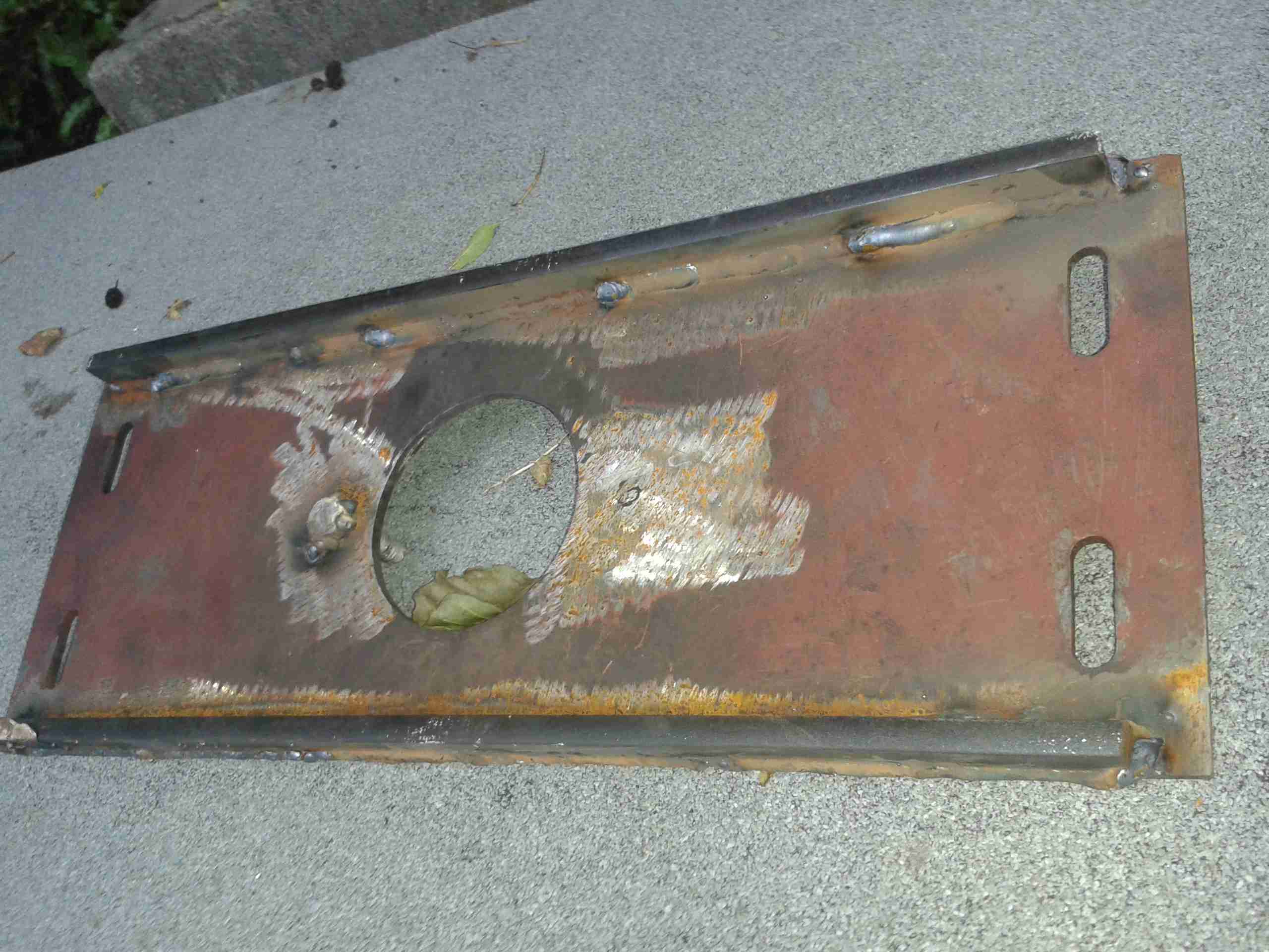
Even though this plate is 10mm steel, under full load it actually bends – so to strengthen it along the long edge, I have welded a pair of ribs to the plate.
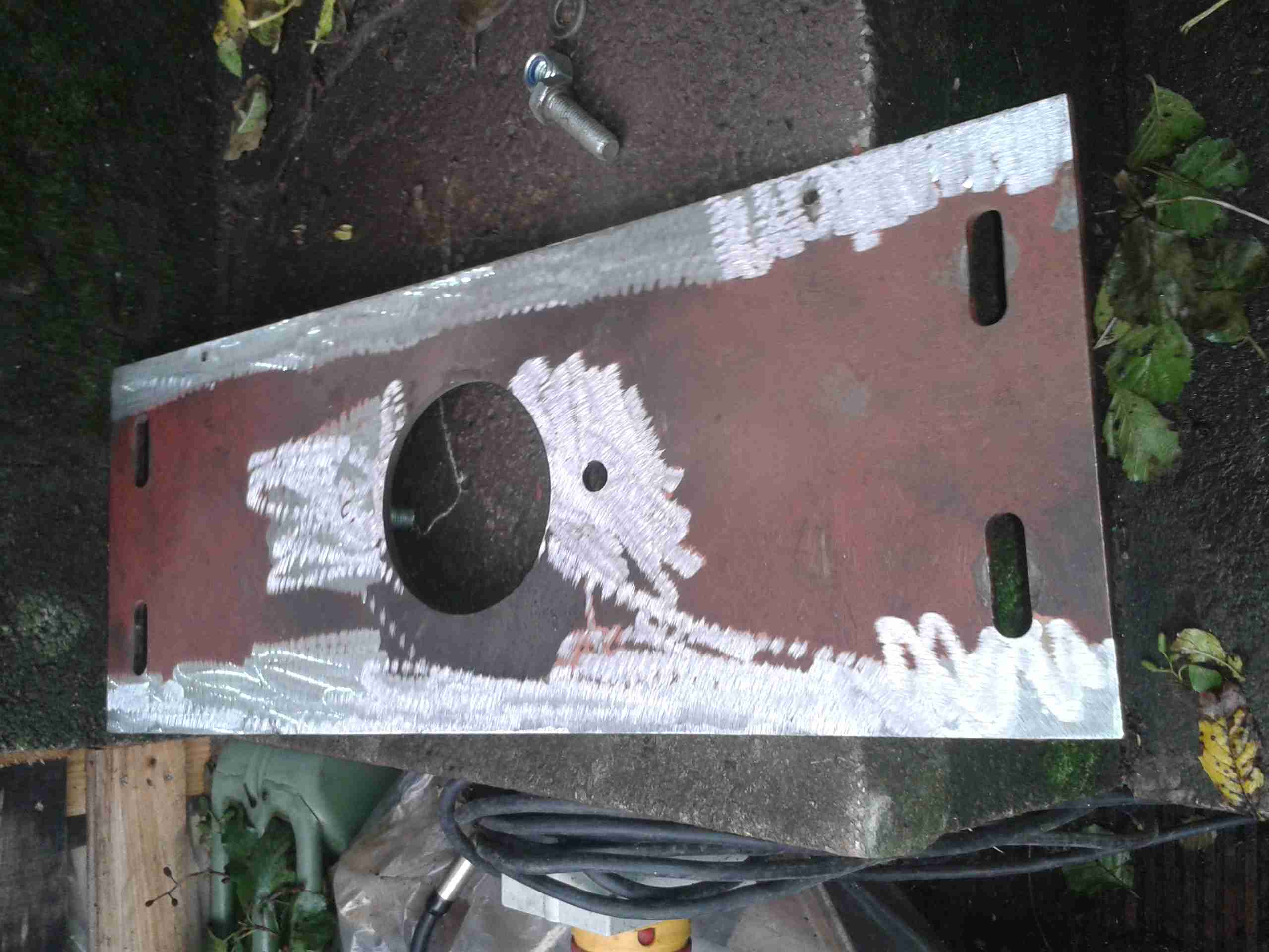
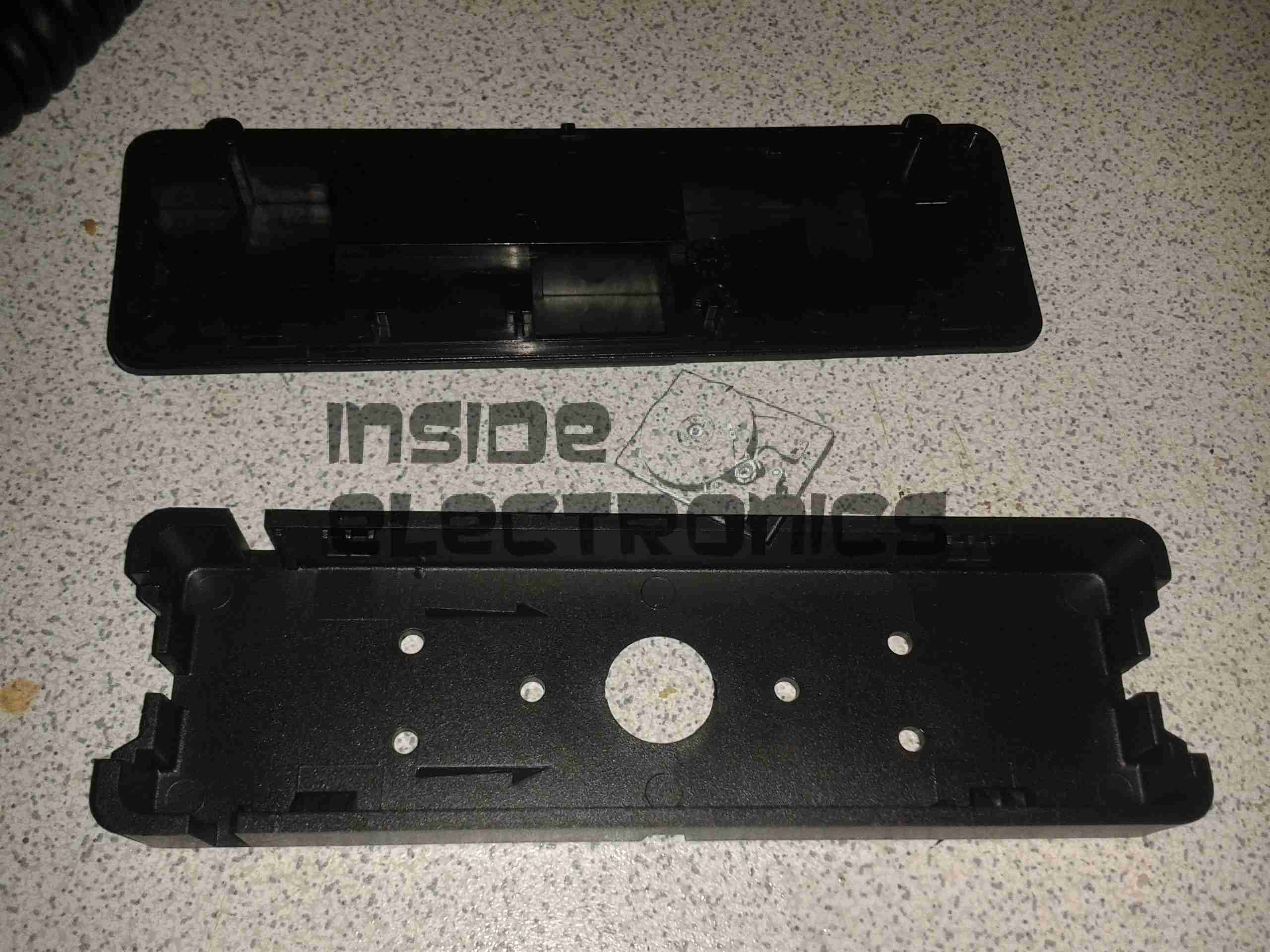
Pump Mounting Plate
The mounting plate as removed from the mounting brackets. The slotted holes at the sides allow for some movement to adjust the position of the pump & flywheel coupling.
Prepared For Welding
I ground off the paint & grease with an abrasive disc, and am replacing one of the pump mounting studs while I’m at it.
Strengthening Ribs
Here’s the plate after welding. a pair of 10mm bars have been attached along the edges, this will give the mounting significantly more strength on the long axis & prevent any deformation.
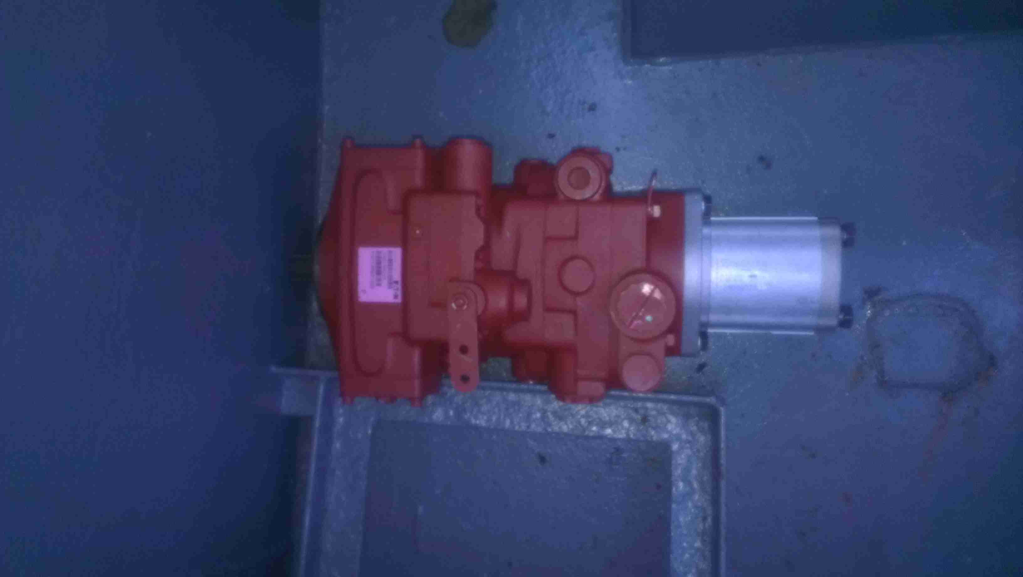
Pump On Hoist
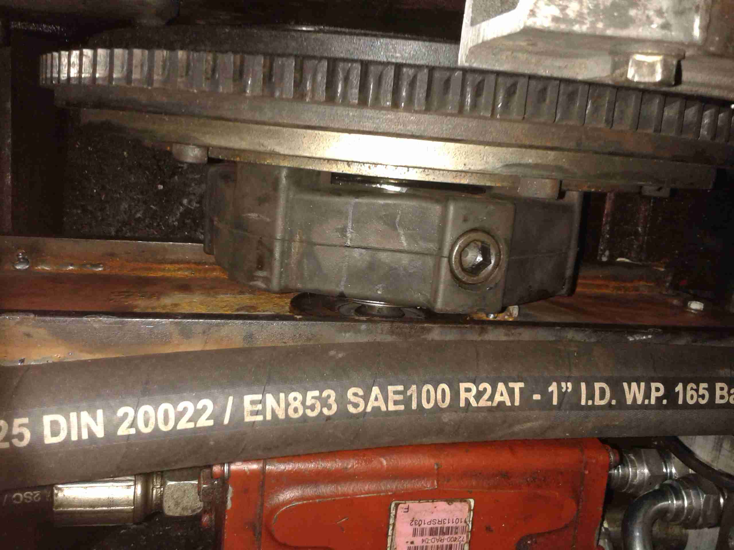
Here the plate has been loosely mounted on it’s brackets, & I’ve got the pump stack with it’s associated tangle of hoses on the chain hoist. This unit is very heavy on it’s own – a 2 man job to lift it into place on it’s mounts – with the very stiff hydraulic hoses attached & filled with oil it’s absolutely unmanageable.
Lining Up The Mountings
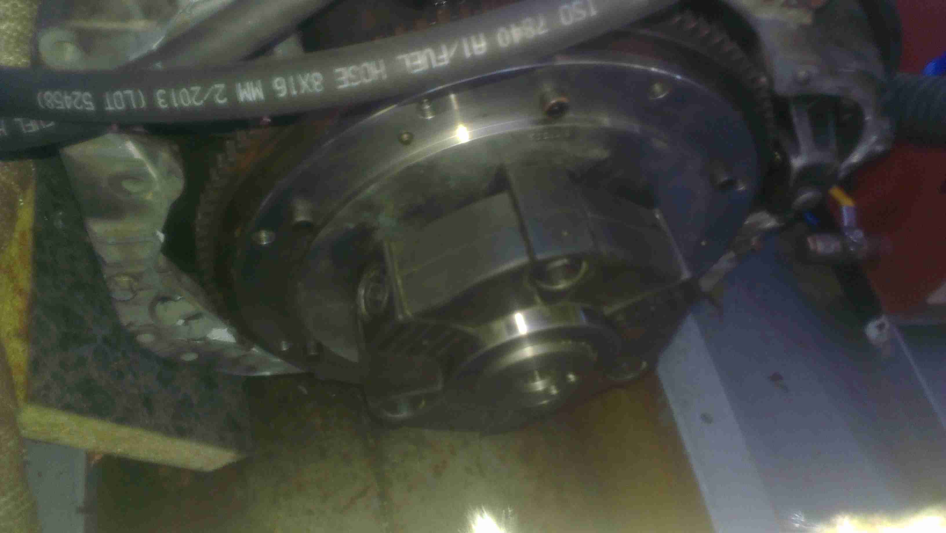
Here the pump is being jostled into place. The central hole in the mounting plate is a very snug fit, if the pump doesn’t go in exactly straight it will jam & cause damage to both parts. The mating hole in the coupling hub can be seen here – it’s not quite lined up yet.
Almost There
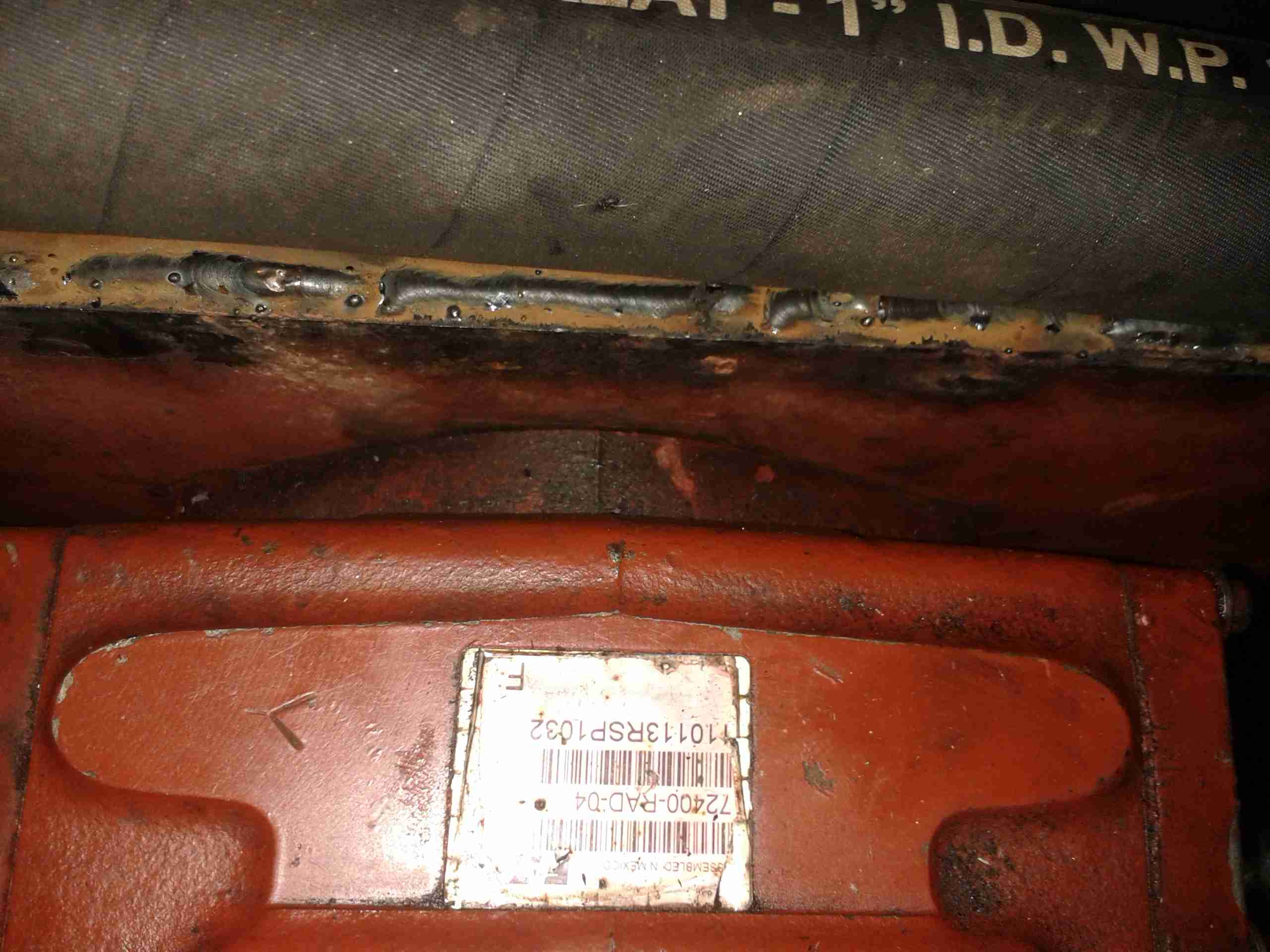
We’ve got about 10mm to go before the pump is seated. It’s held in place with a pair of large studs & nuts.
Coupling Connected
Here the pump is fitted enough to get the main mounting bolts into the coupling. These are torqued down to 150ft/lbs – a difficult thing to do considering the restricted space in the engine bay.
Flush Mounting
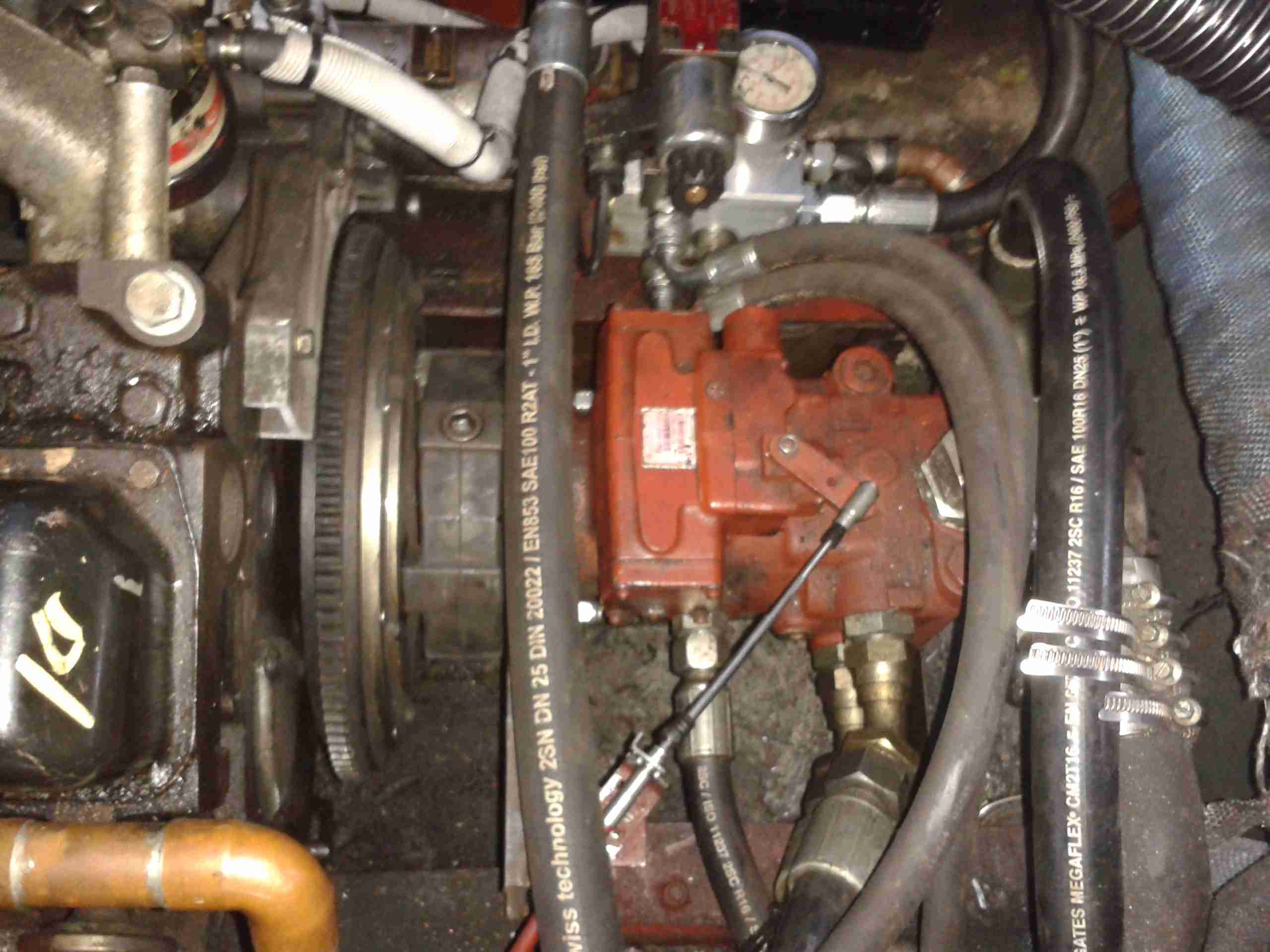
The pump has been pulled down onto the plate evenly with the mounting studs, and is now completely flush with the plate. As can be seen, I didn’t bother tidying up the welds with a grinder, they aren’t in any visible place in normal operation, so it didn’t warrant the effort.
Pump Refitted
Finally, the control cable is reattached to the pump’s control lever & everything is installed! A short test trip proved that everything was stable & no undue movement of the pump or coupling was noticed.
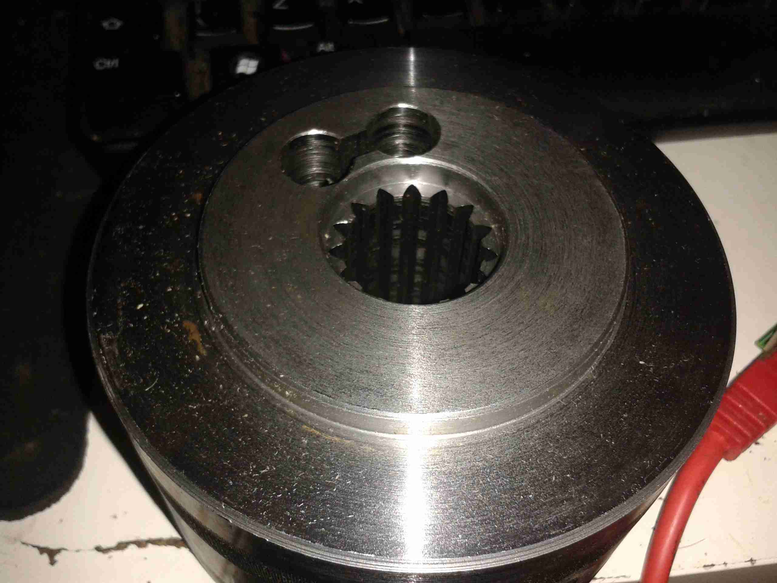
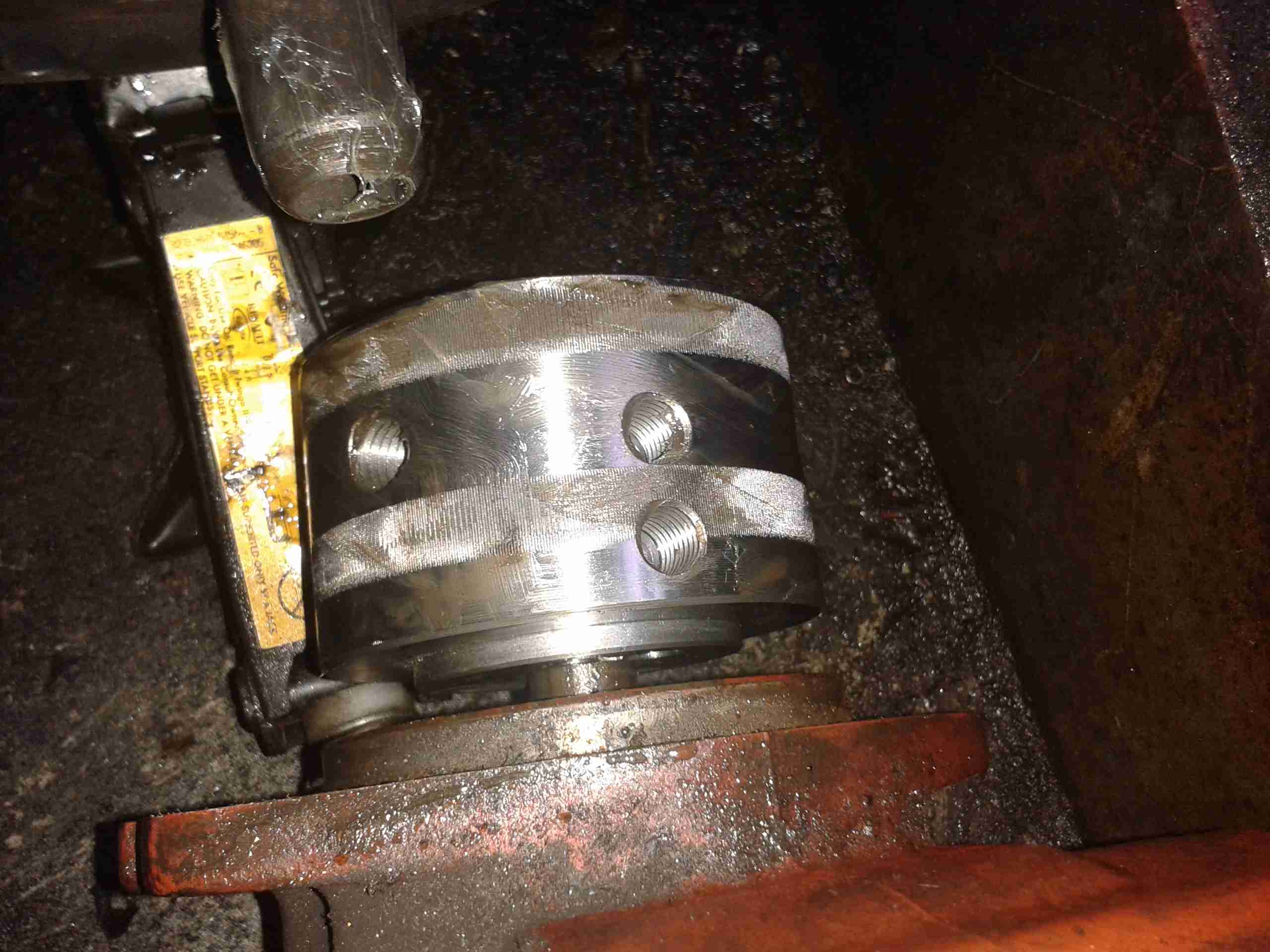
Time to get on with the job now the parts have arrived! Above is the new coupling hub, as can be seen compared to the old one that I previously posted about, this one has it’s full complement of splines.
Rubber Element
The hub bolts into the centre of this rubber coupling, which itself locates on pins attached to the engine’s flywheel. This part wasn’t damaged so it’s being reused with the new hub.
Hub Installed
Here’s the hub installed on the input shaft of the main hydraulic pump stack, the pair of holes on the side of the hub are for the grub screws that secure the coupling on the splines. These screws coming loose are what destroyed the old coupling.
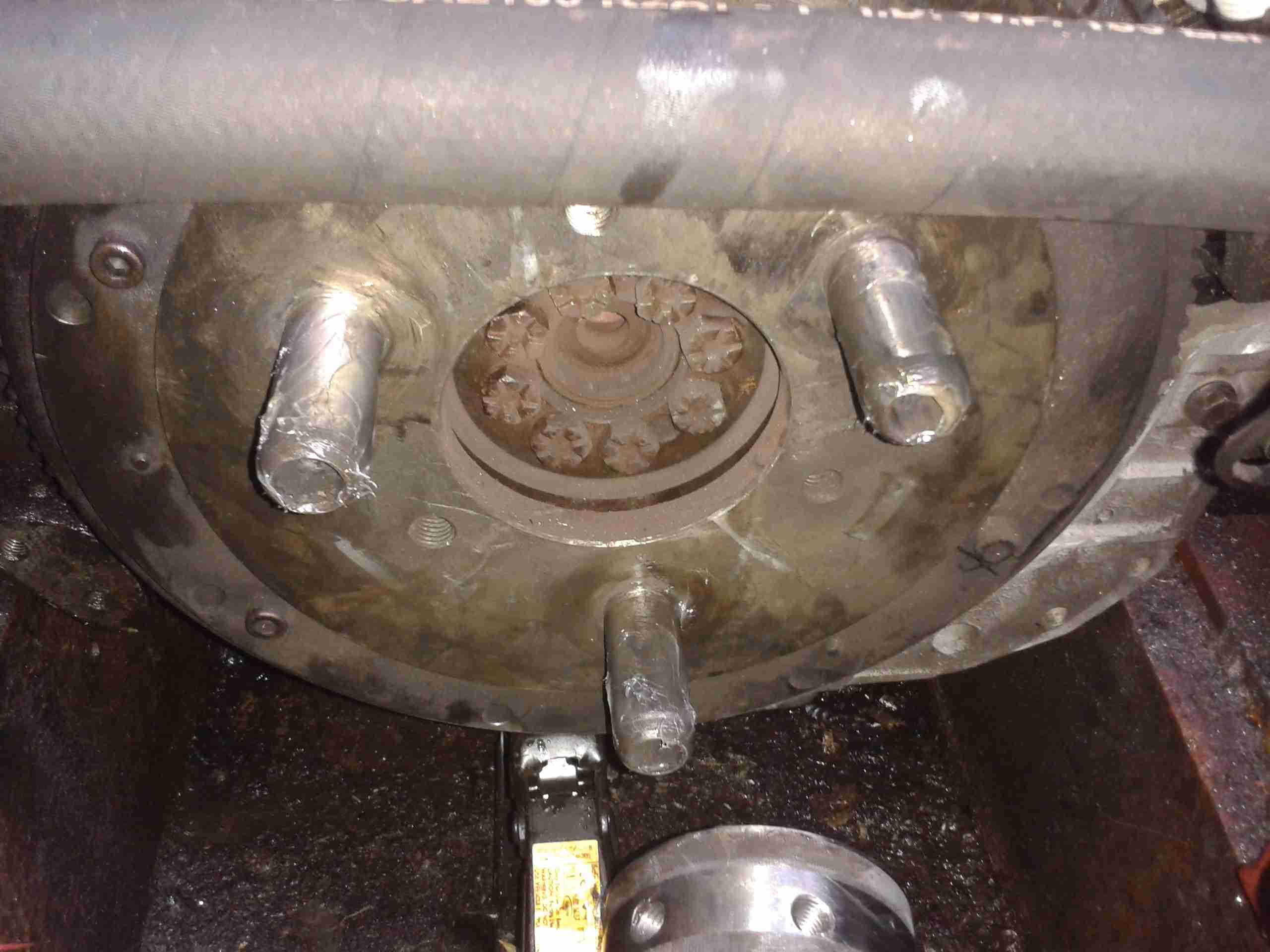
Flywheel
Here’s the engine flywheel, where the rubber coupling normally sits. The mounting pins have been greased ready to accept the rest of the coupling.
Doughnut
Here’s the rubber element mounted on the pins – there’s nothing holding it there in normal operation apart from the mating side of the coupling with the pump.
Unfortunately the weather here in Manchester has prevented us from getting any further – more t0 come when the rain stops!
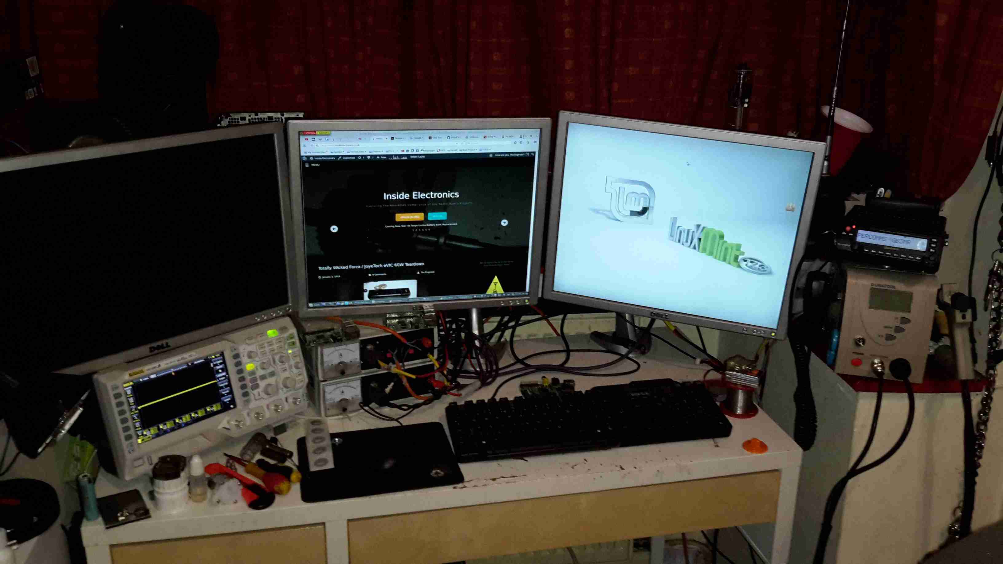
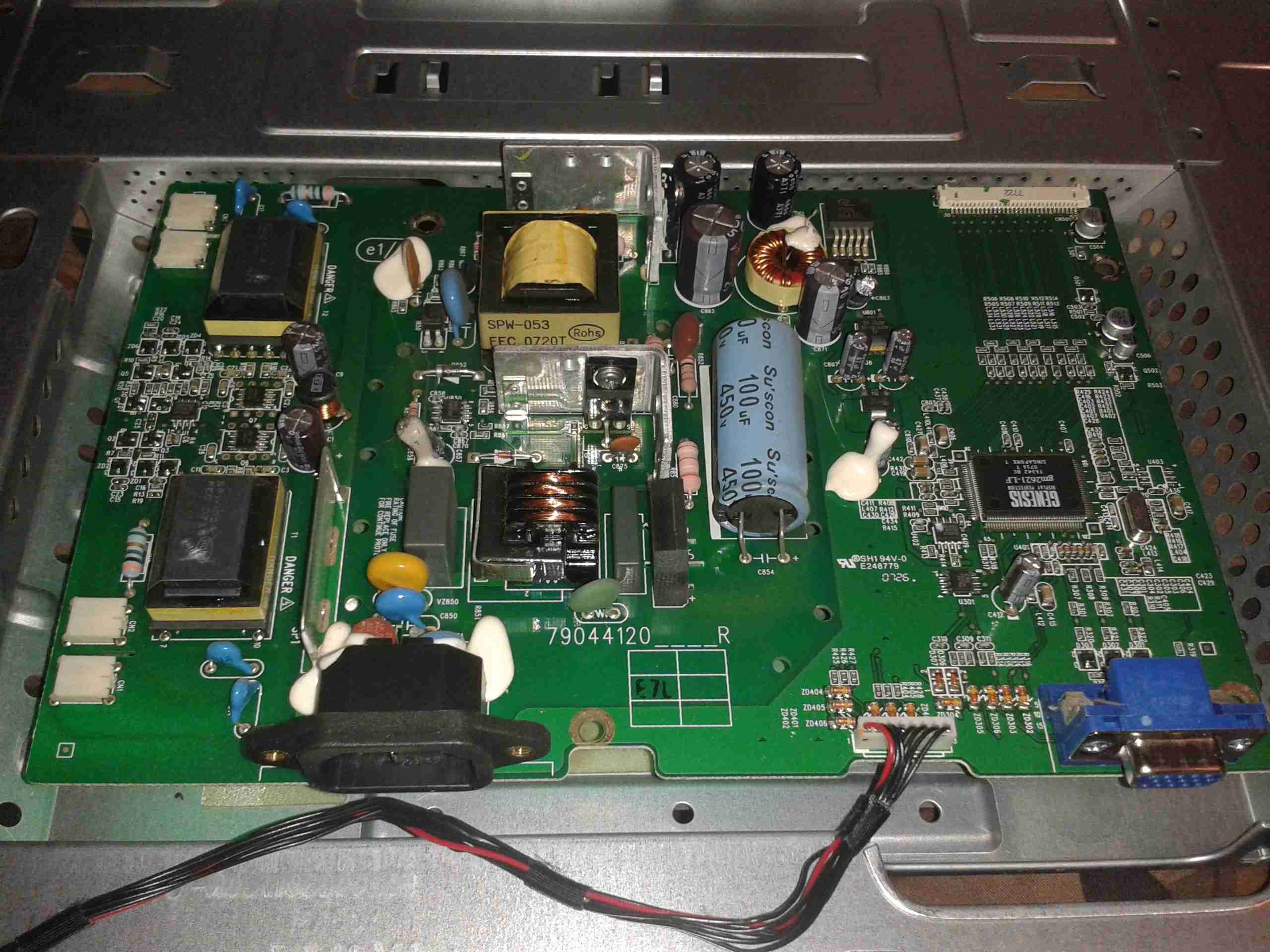
Main radio of course is housed on the left, it’s partially hidden under my currently over-populated breadboard.
All 3 monitors are linked to the same PC, using a pair of video cards. This is a very flexible system with so much screen real estate.
Main system power is provided by the pair of power supplies next to the radio – these are homebrew units using surplus switched mode PSU boards. Check my previous posts for more details.
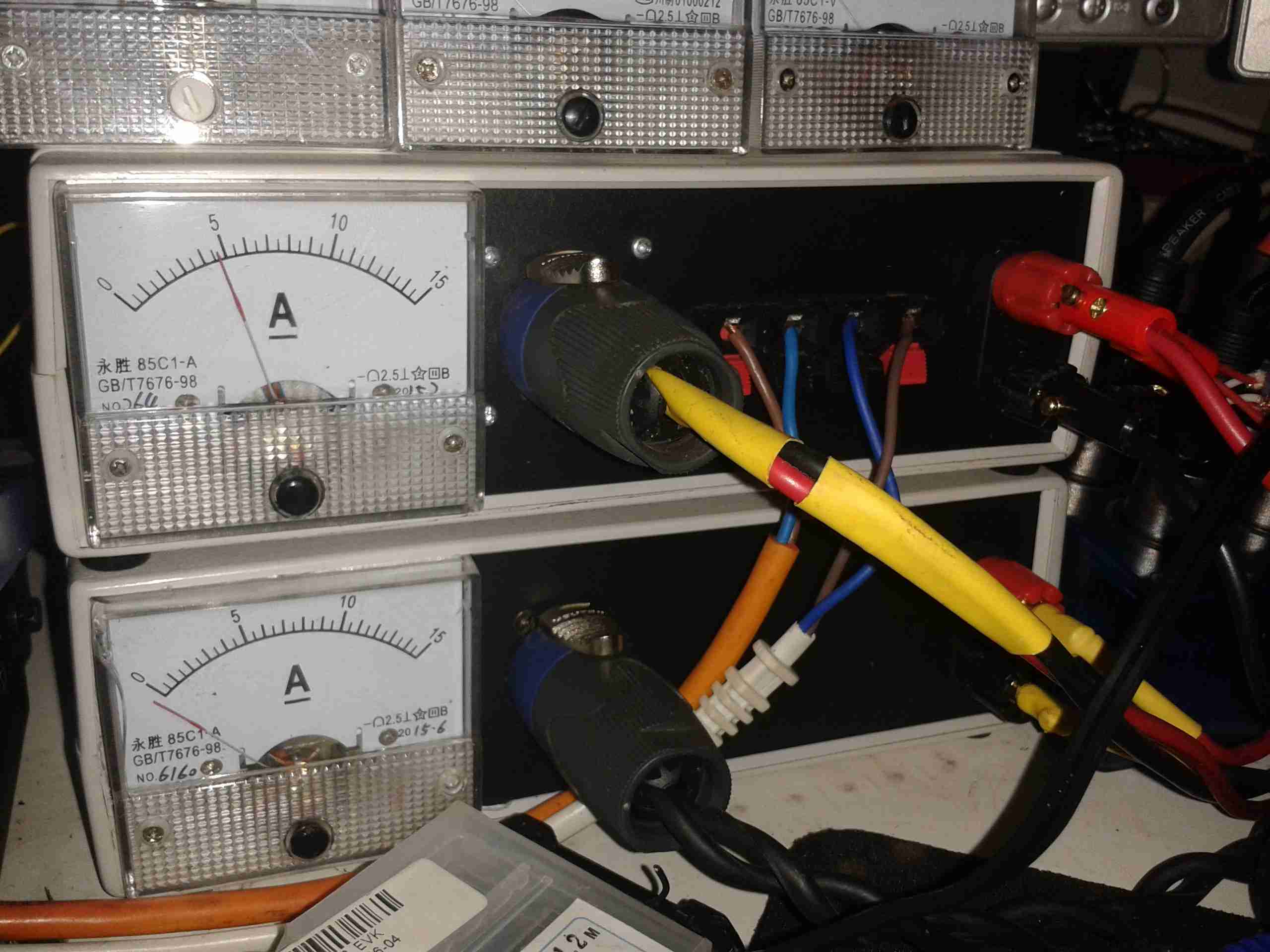
Power Supplies
The mainpowersupply system. These two supplies are cross connected, giving a total DC amperage of 30A at 13.8v. There is also a link to a large 220Ah lead-acid battery bank (orange cable), to keep me on the air during power outages. This cable is getting upgraded to something more beefy shortly. The white cable is currently supplying power to my onlineradiation monitor.
The main high-currentDC outputs are the Speakon connectors next to the meters. The top one is powering the radio directly, the bottom is linked through to my 12v distribution box for lower current loads, such as the oscilloscope, audio amplifiers, tools, etc.
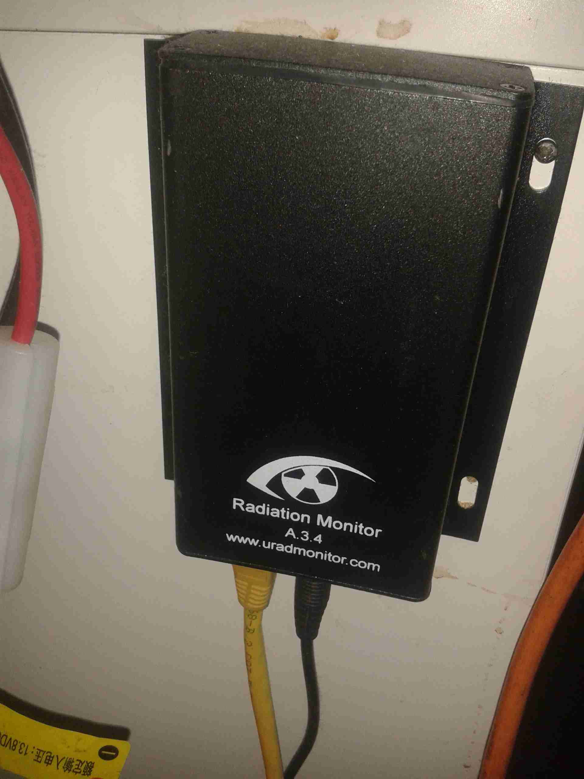
Radiation Monitor
Attached to the side of the desk is the radiation monitor itself.
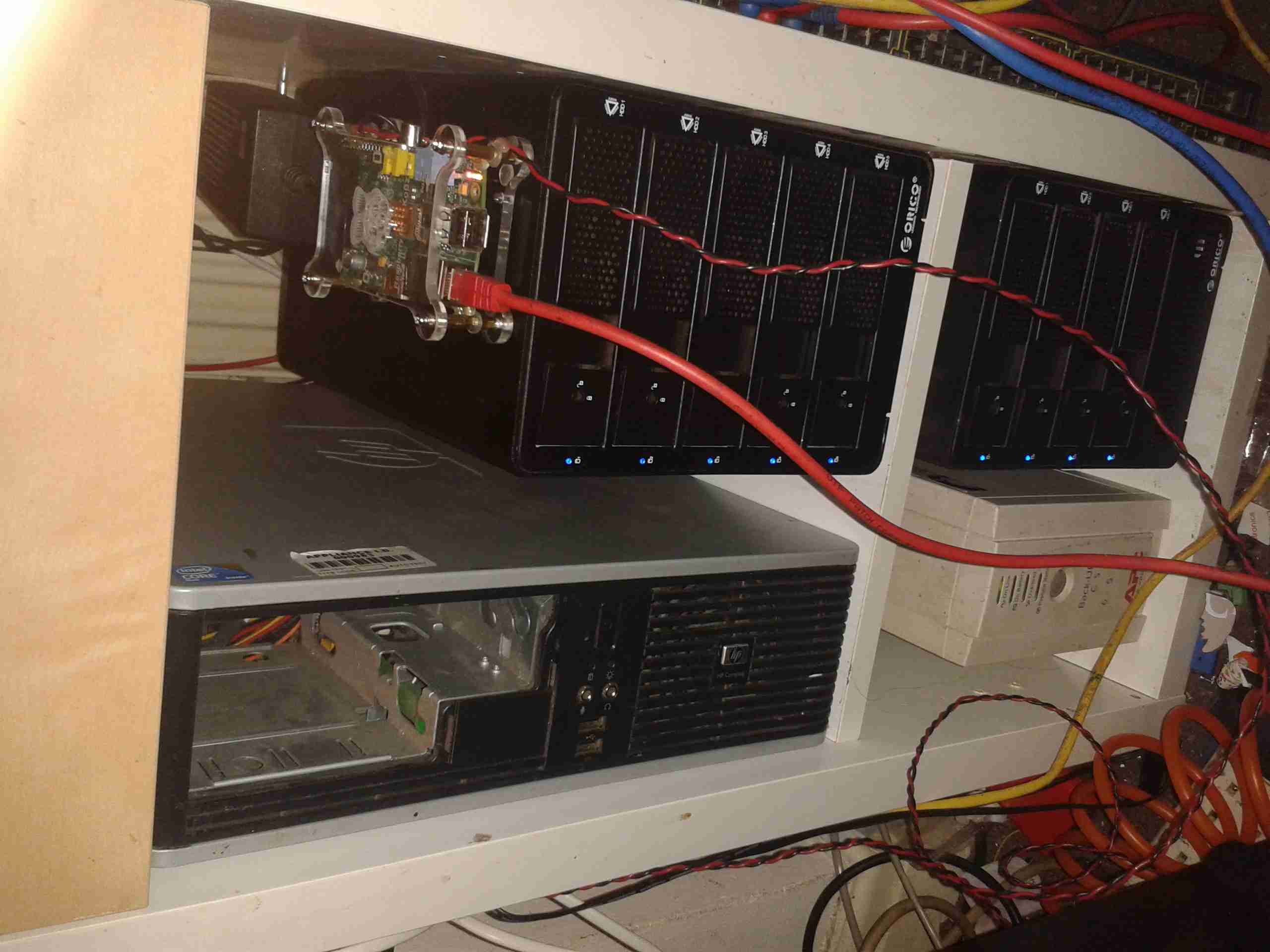
Core NAS
Under the radio is the core NAS of the network. It’s an array of 9 4TB disks, in RAID6, giving a total capacity after parity of 28TB. This provides storage & services to every other machine in the shack, the Raspberry Pi on top of the disk array is doing general network housekeeping & monitoring, also generating the graphs for the Radiation Monitor page. A Cisco 48-portswitch is partially out of frame on the right, providing 100MB Ethernet to the devices that don’t require gigabit.
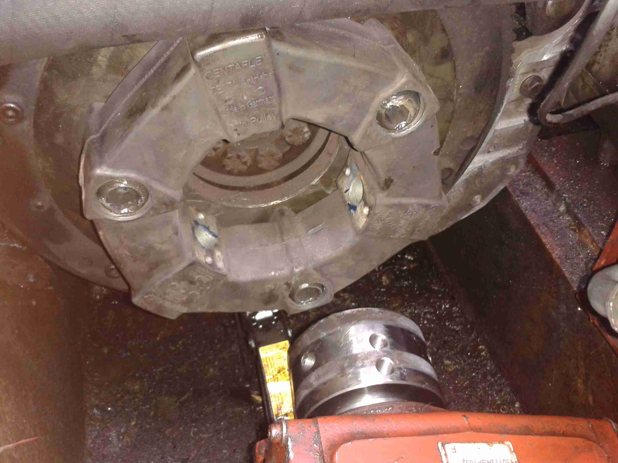
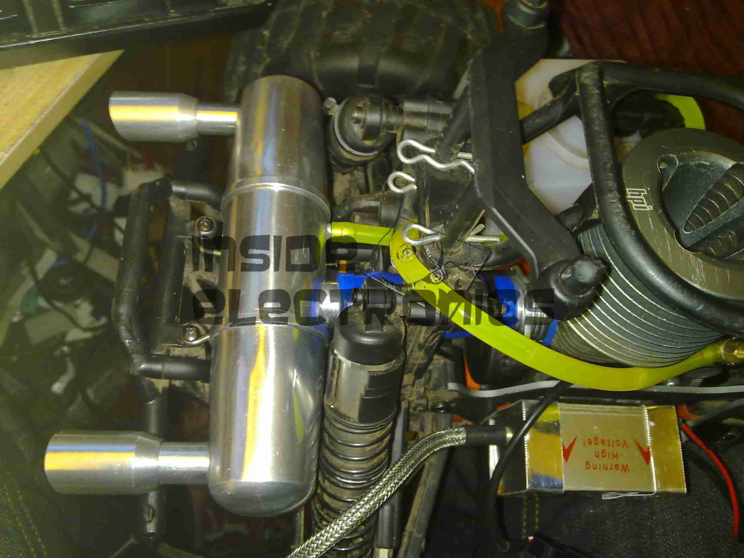
As I have posted about before, the main propulsion system onboard the boat is all hydraulic. To get the drive from the flywheel of the engine to the hydraulic pump stack, a custom drive plate was machined by Centa Transmissions over in Yorkshire, and a Centaflex A coupling was fitted to this.
Centaflex A Coupling
This coupling is a big rubber doughnut, bolted to a centre hub of steel. The steel hub is splined onto the input shaft of the hydraulic pump stack.
Pump Stack
The problem we’ve had is that to prevent the coupling from riding along the splines in operation, a pair of giant grub screws are provided in the side of the centre steel boss, that compress the splines to lock the device in place. These screws are a nightmare to get tightened down (the engineer from Centa who originally came to survey the system said we’d probably shear some tools off trying).
Because of this, the grub screws have loosened over the last 350-odd hours of running & this has had the effect of totally destroying the splines in the hub.
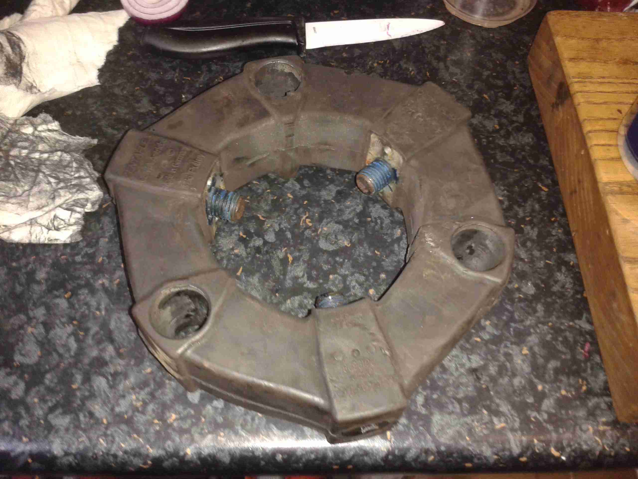
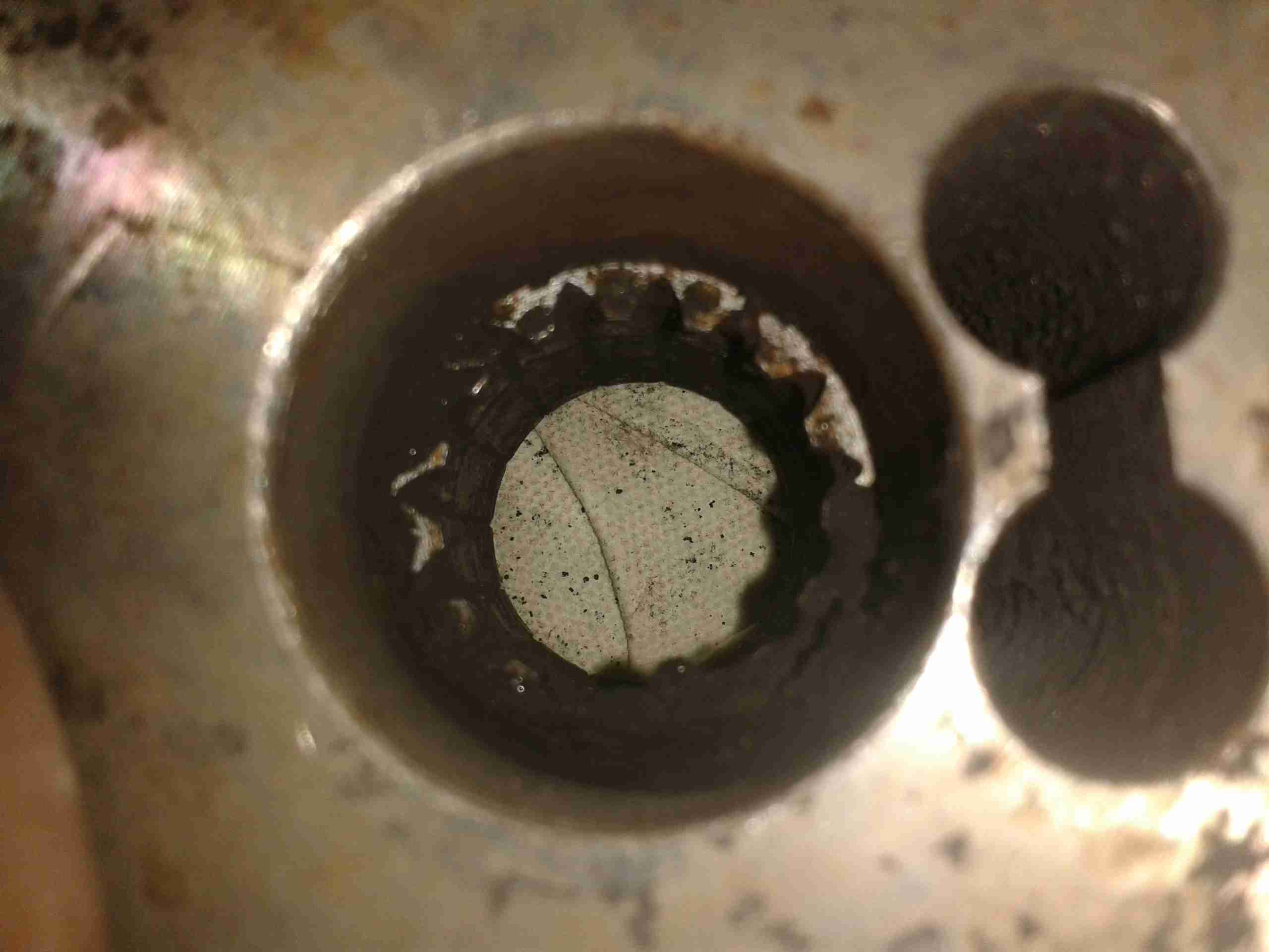
Spline Remains
Here’s the backside of the centre boss, with what remains of the splines, the figure-8 shaped gap on the right is where the securing grub screws deform the steel to lock the coupling into place.
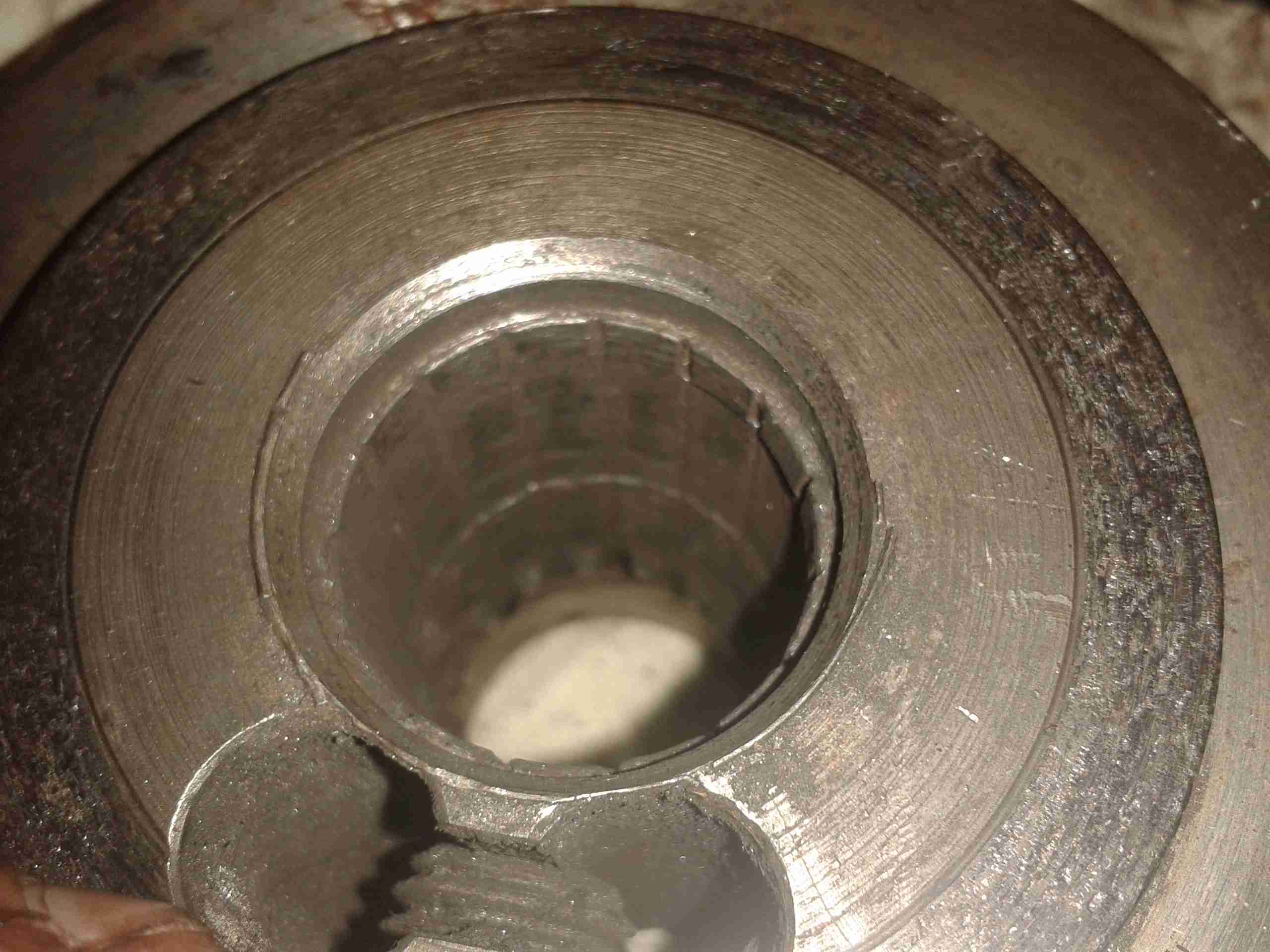
No More Splines
Here’s the other side of the coupling, showing the damage. The splines have effectively been totally removed, as if I’d gone in there with a boring bar on the lathe. Luckily this part isn’t too expensive to replace, and no damage was done to the input shaft of the hydraulic pump stack (Mega ££££). Quite luckily, this damage got to the point of failure while running the engine on the mooring, so it didn’t leave us stranded somewhere without motive power.
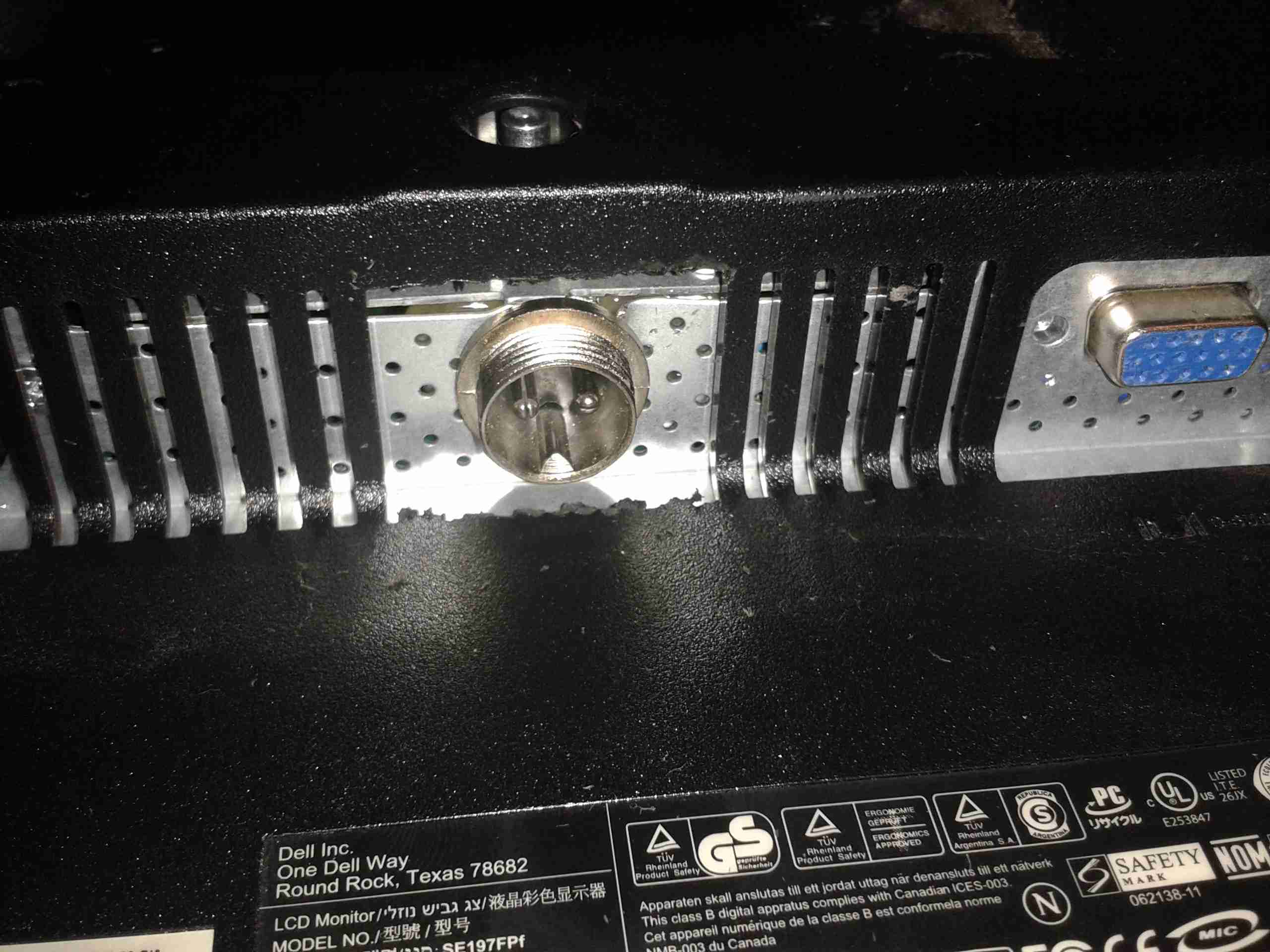
My other monitors are a different model, and have a slightly different main PCB inside, but the process is mostly the same for converting these to 12v supply.
Main PCB
In this monitor type, there is only a single board, with all the PSU & logic, instead of separate boards for each function.
PSU Closeup
This monitor is slightly different in it’s power supply layout. The mains supply provides only a single 12v rail, which is then stepped down by a switching converter to 5v, then by smaller linear regulators to 3.3v & 1.8v for the logic. This makes my life easier since I don’t have to worry about any power conversion at all.
PCB Reverse
Here’s the backside of the PCB, the mains PSU section is in the centre.
Attachment Points
Here’s the pair of 12v supply wires soldered onto the main board, onto the common GND connection on the left, and the main +12v rail on the right. I’ve not bothered with colour coding the wiring here, just used whatever I had to hand that was heavy enough to cope with a couple amps.
12v Socket
A small mod later with a cone drill & the 12v input socket is mounted in the LCD frame.
Casing Mod
Some light removal of plastic & the back cover fits back on. Current draw at 13.8v is ~2A.
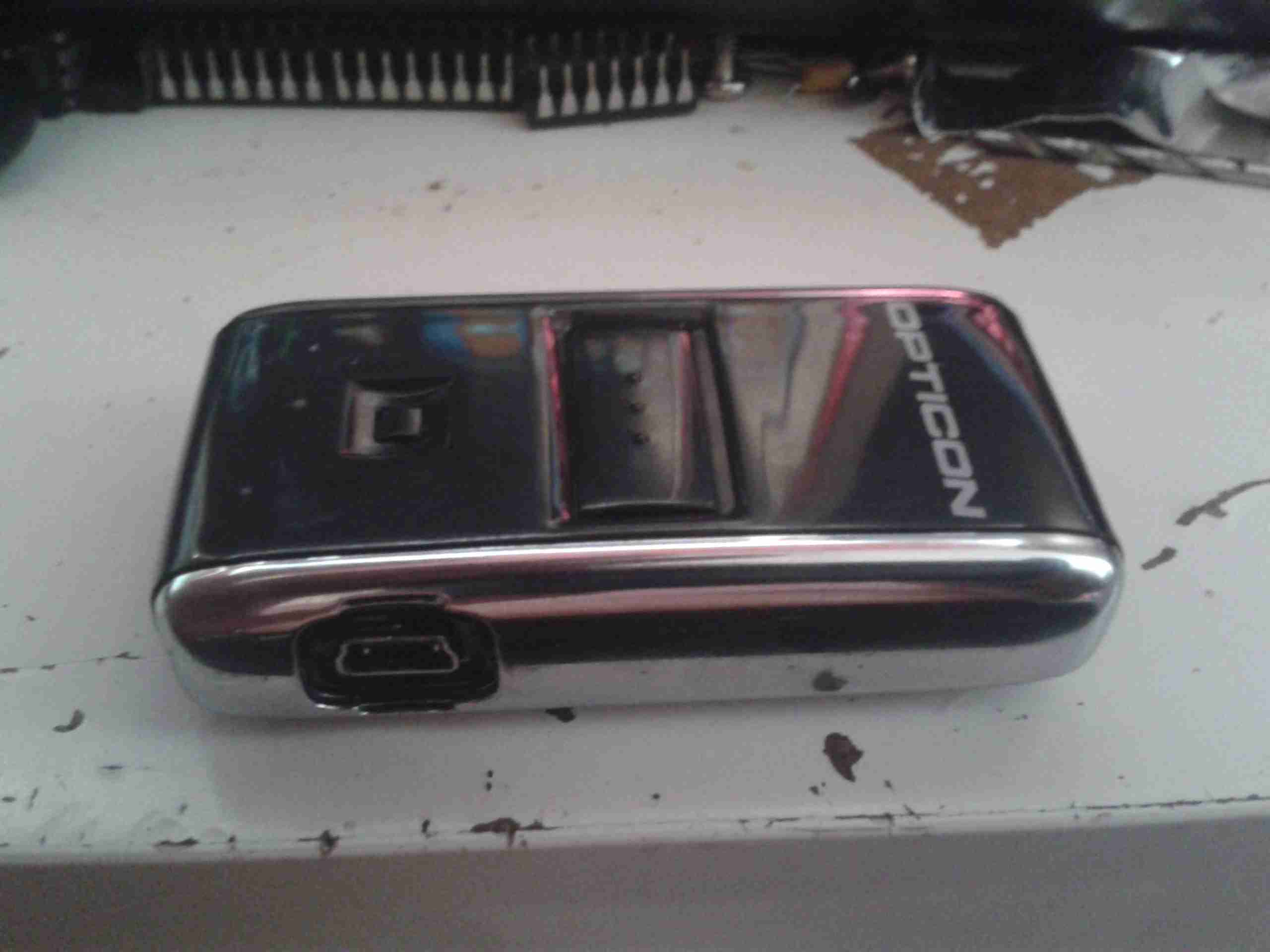
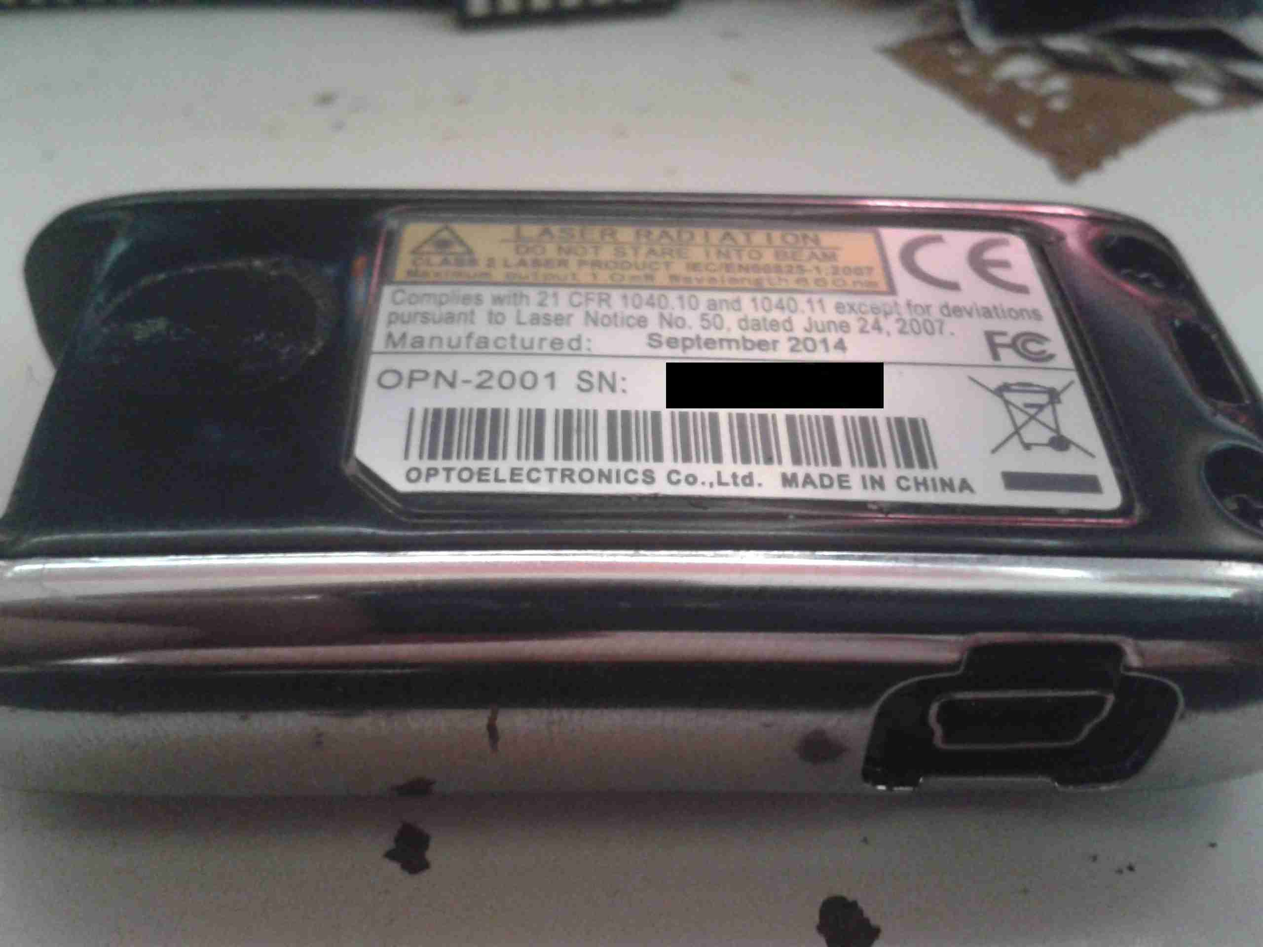
The OPN-2001 is a very small handheld barcode data collection device, used for stock keeping, inventory, etc.
It’s powered by an internal Li-Poly cell, at 150mAh, and has storage for 1000 barcodes in it’s internal memory.
USB
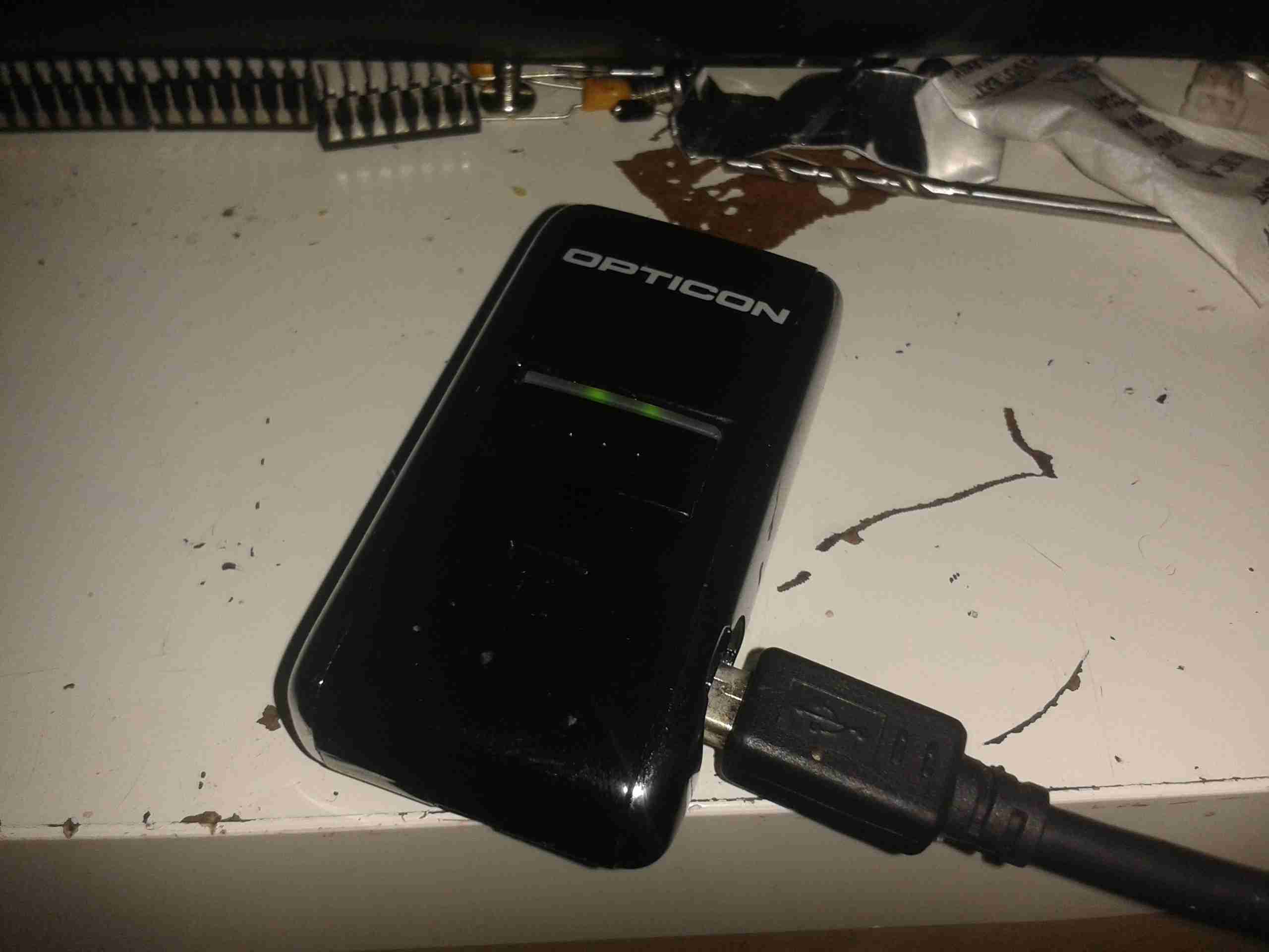
The unit is charged via it’s USB port, the data can also be downloaded using this interface.
ID Label
Here’s the bottom of the unit with it’s label. Serial number removed to protect the guilty. 😉
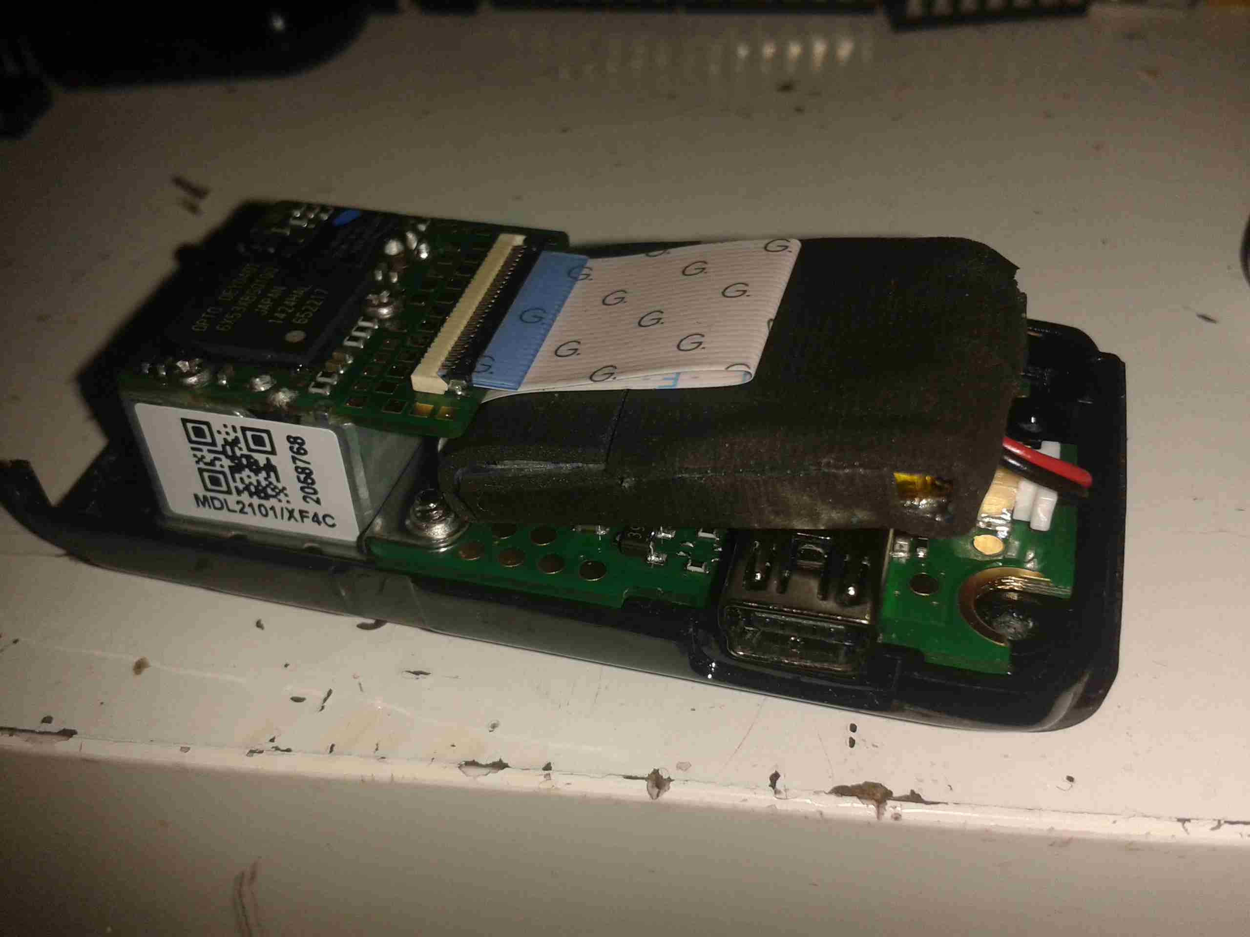
Cover Removed
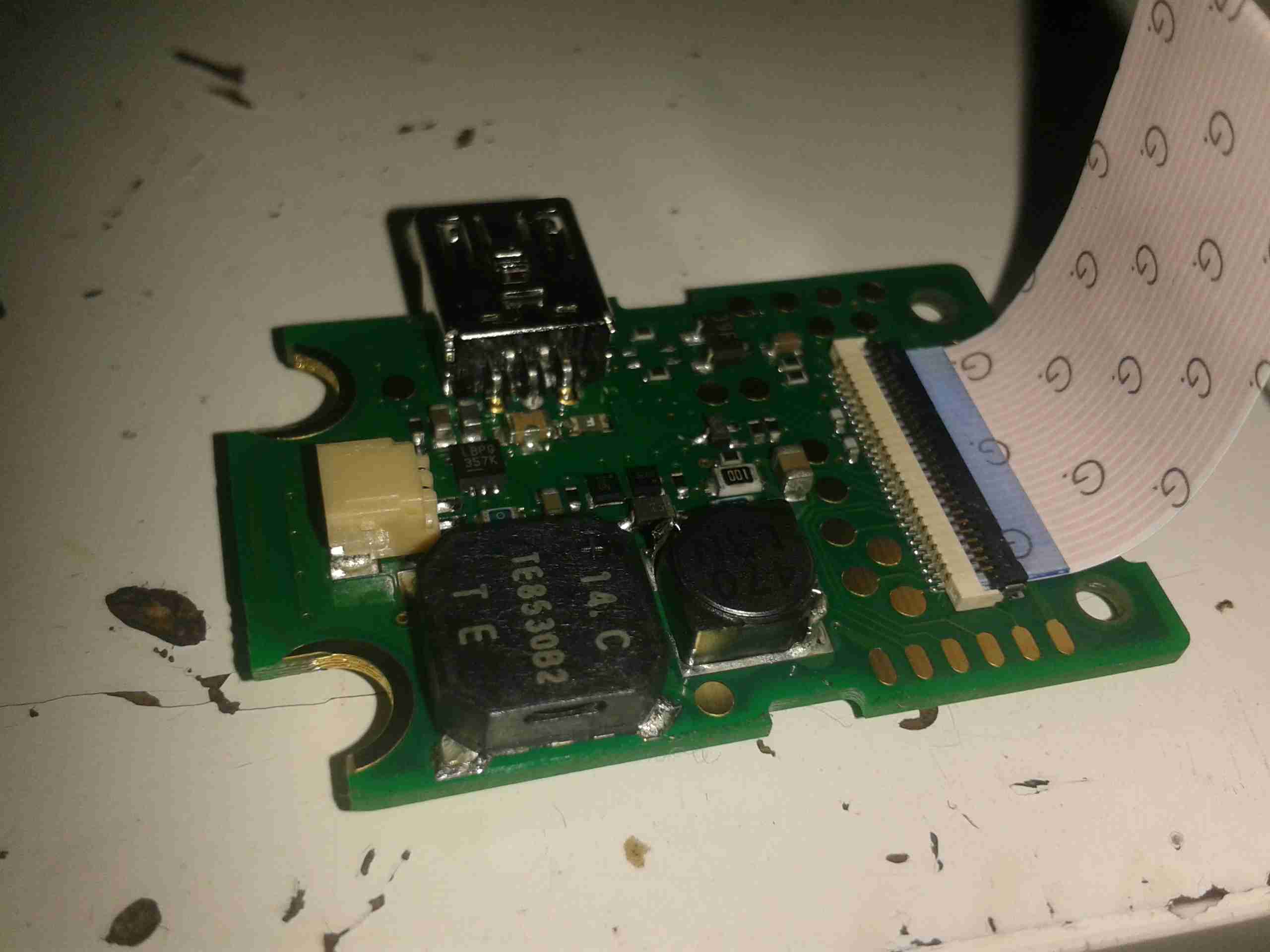
Here the bottom cover has been removed from the scanner, showing the internals. The barcode engine is on the left, this contains all the hardware & logic for scanning & storing the barcode data. The Li-Poly cell is under the FFC cable wrapped in foam tape for protection.
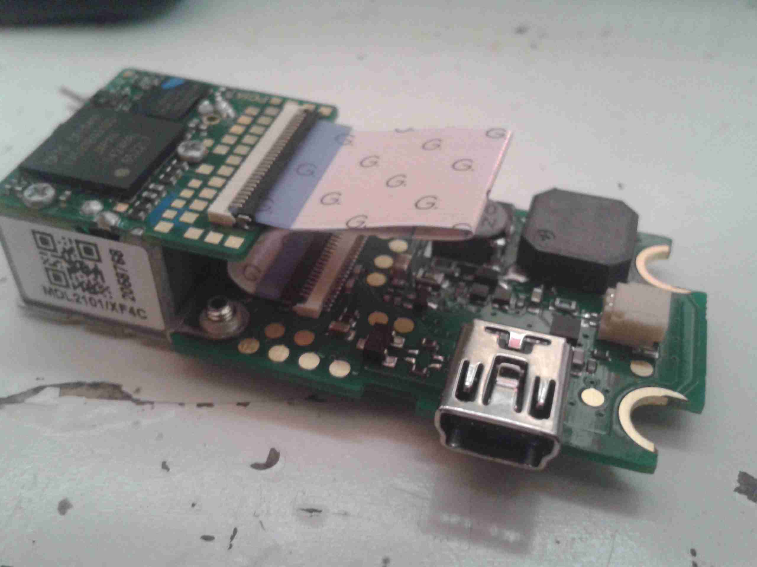
PCB Removed
Here’s the PCB & engine assembly removed from the casing. The lower PCB appears to just handle the user interface buttons, beeper & USB power & charging circuitry. All the processing logic is on the barcode engine itself.
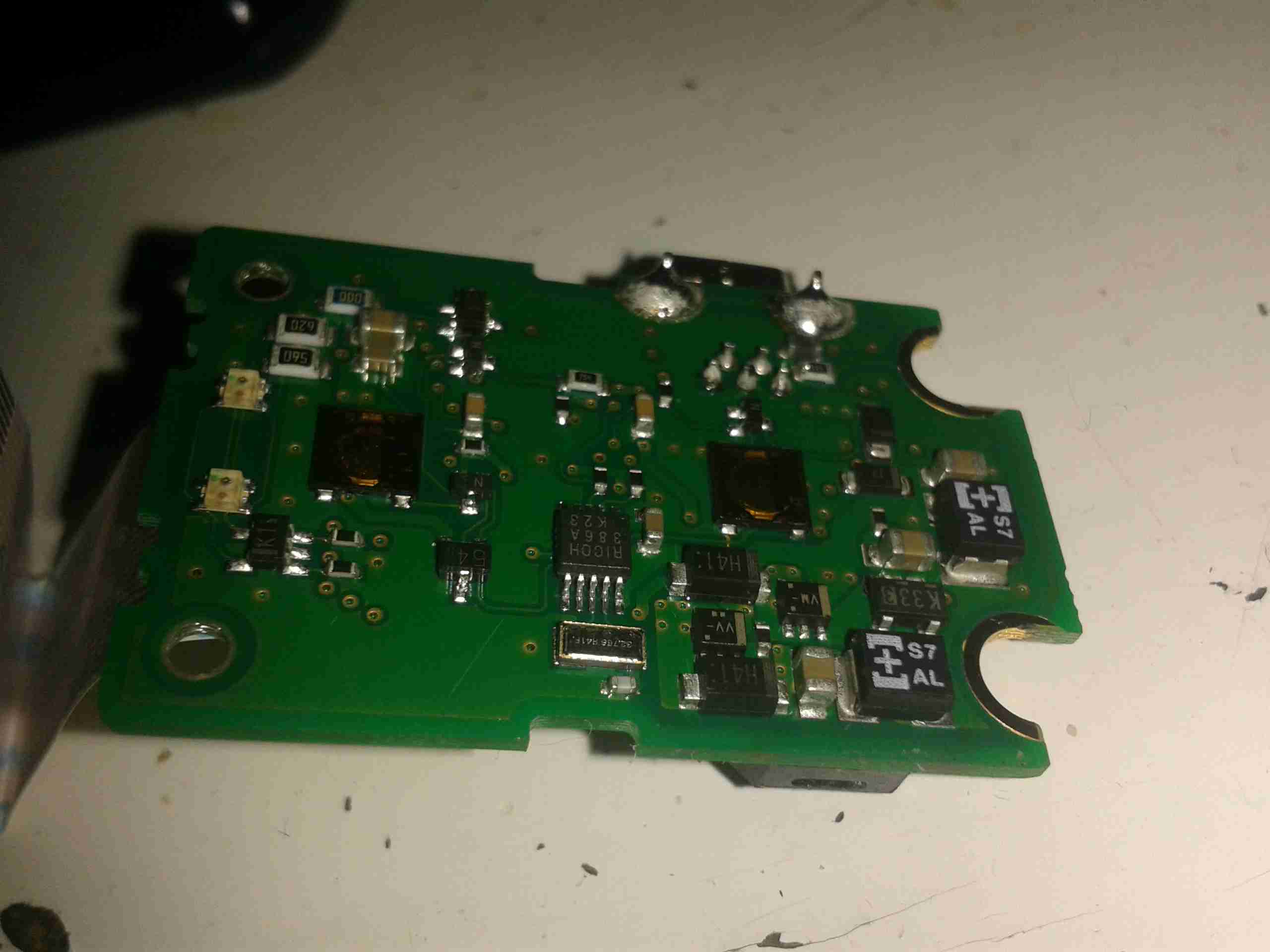
PCB Reverse
Here’s the back of the support PCB, with the pair of buttons for scanning & deleting barcodes. Also on this board is a 32kHz clock crystal & a Ricoh RV5C386A RTC IC. This communicates with the main processor via I²C for storing the date & time with the barcodes. At the bottom right corner are some of the power supply passives.
Support PCB
Here’s the other side of the support PCB, with the beeper, battery connector & the switching regulator to provide the barcode engine with 3.3v power.
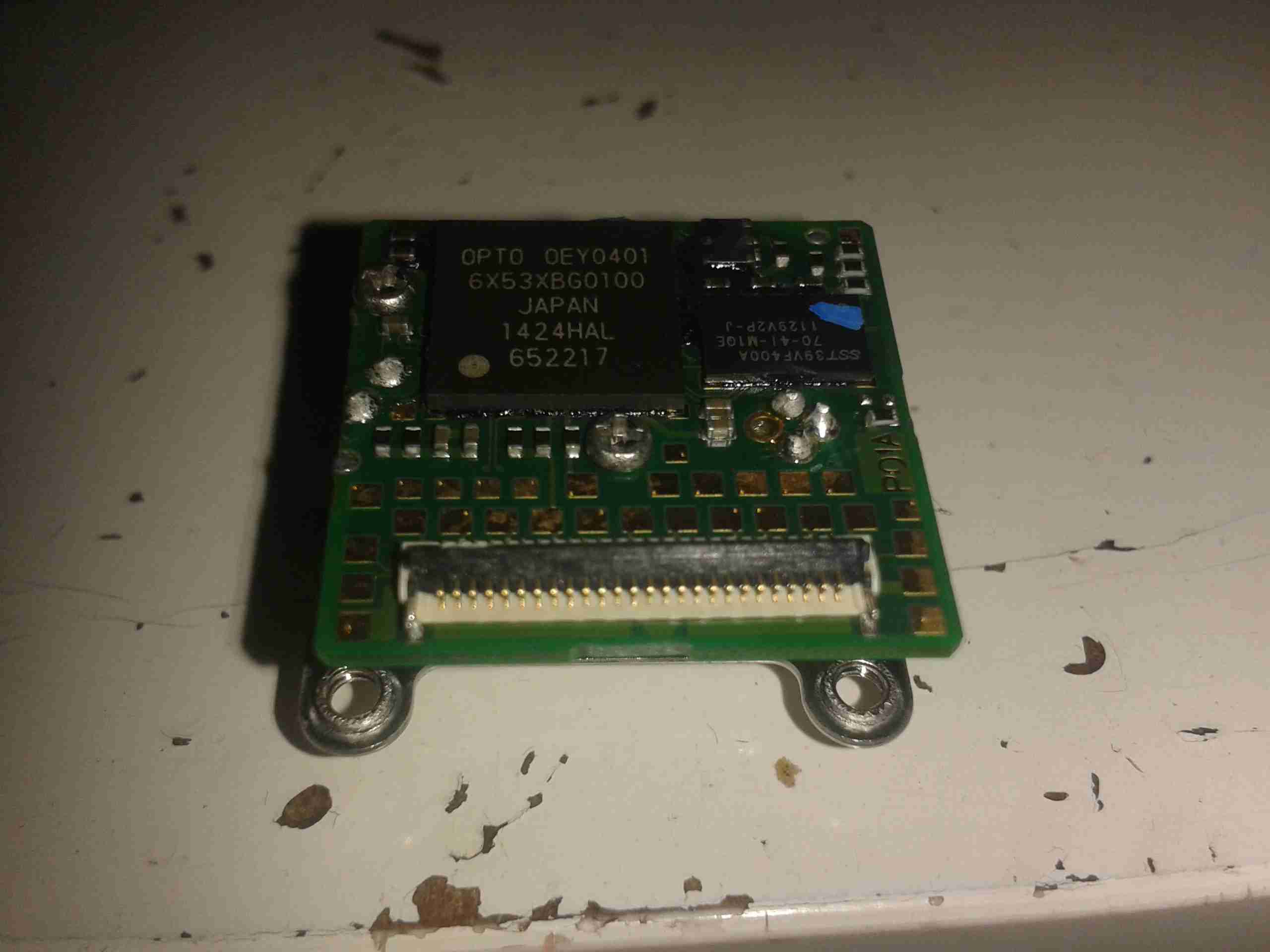
Barcode Engine
Here’s the barcode engine itself, which is absolutely tiny, at roughly 20mm square. The main processor & it’s associated Flash ROM are on this PCB. The main processor has an ARM7 32bit core, with 64kB of RAM, and onboard 512kB of ROM for program & barcode storage.
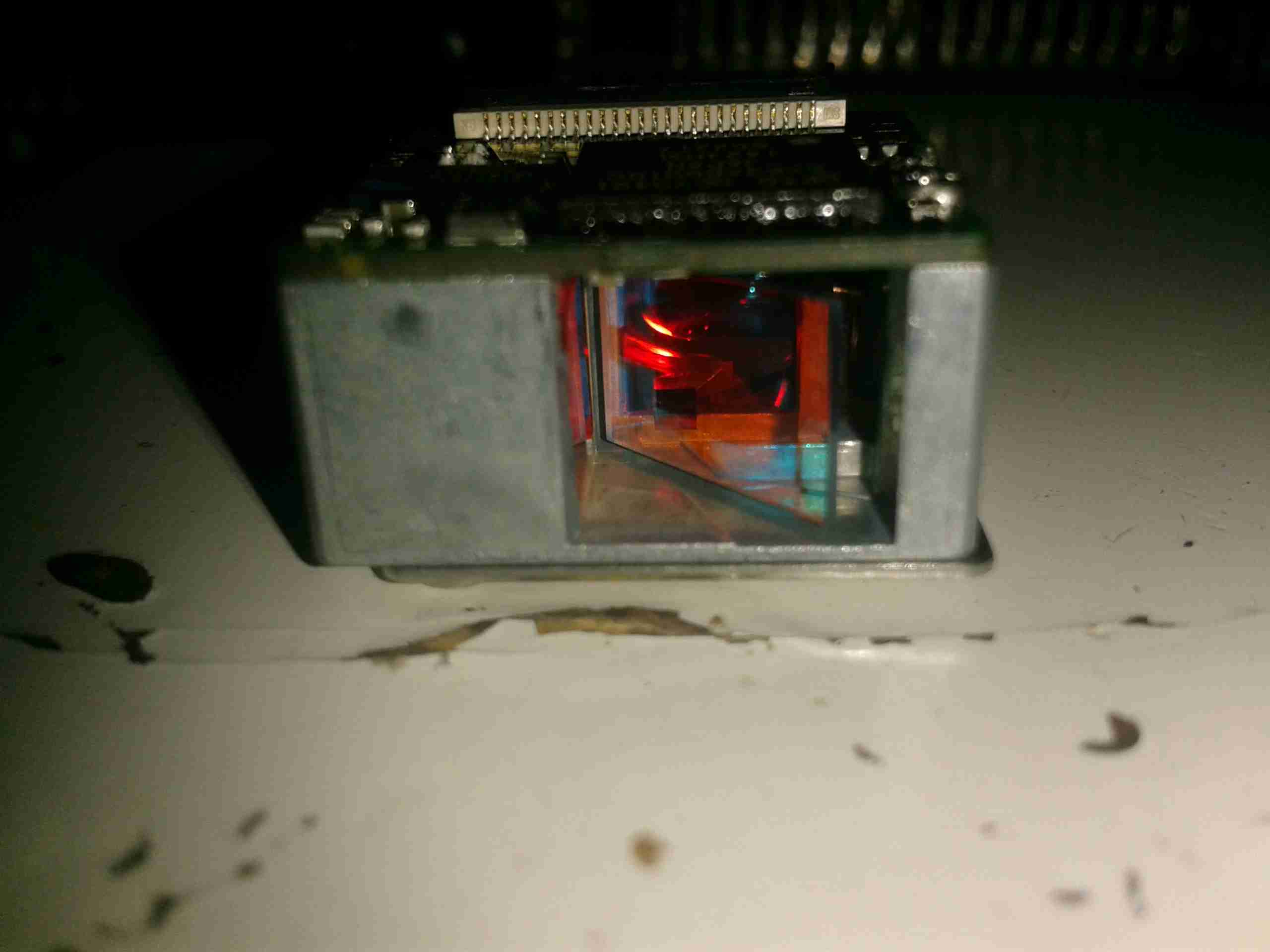
Mirror
Here’s the business end of the barcode engine, the mirror vibrates at 100Hz to produce the scan line. The laser diode is rated at 1mW, 650nm. This is in the deep red range.
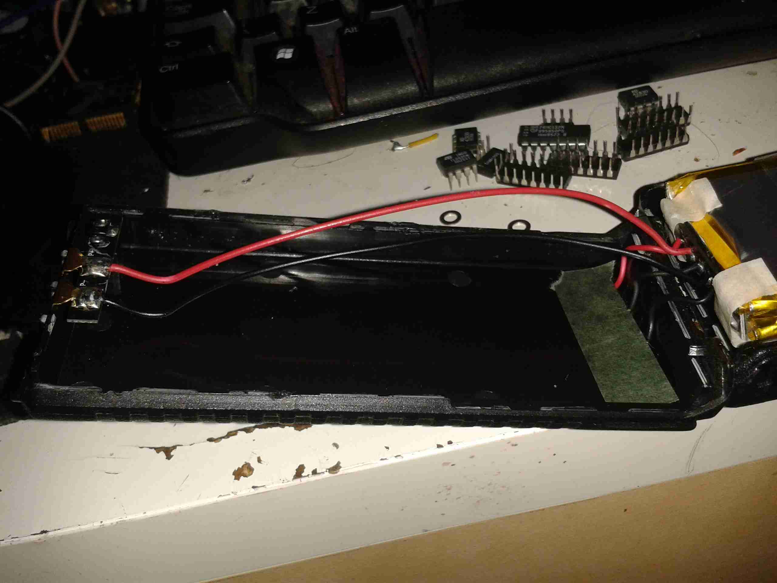
I’ve had a couple of larger batteries for my UV-5Rs for some time now, and decided to do a quick teardown to see if they’re actually the capacity claimed.
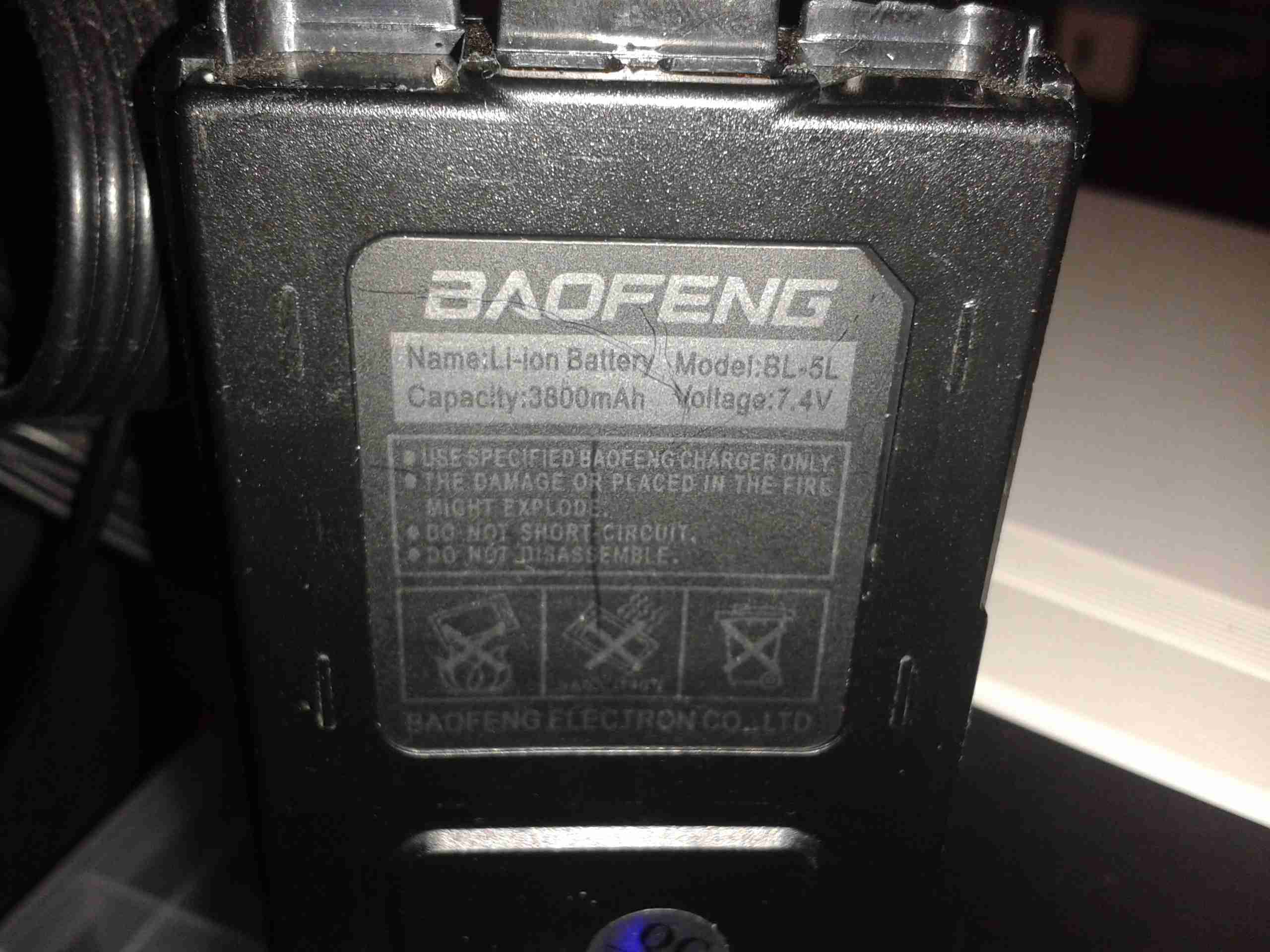
BL-5L Battery
Here’s the label, claiming 3800mAh (3.8Ah) of battery capacity.
These batteries are held together with glue, but a good way to get these kinds of things open is by whacking the seams with the handle of a screwdriver. This cracks the glue without damaging the casing.
Battery Cracked Open
After a few minutes of cracking the seams, the battery comes right open. The pair of wires link the protection board on the cells to the DC terminals on the top of the pack. The charging terminals are under the cardboard insulator on the right.
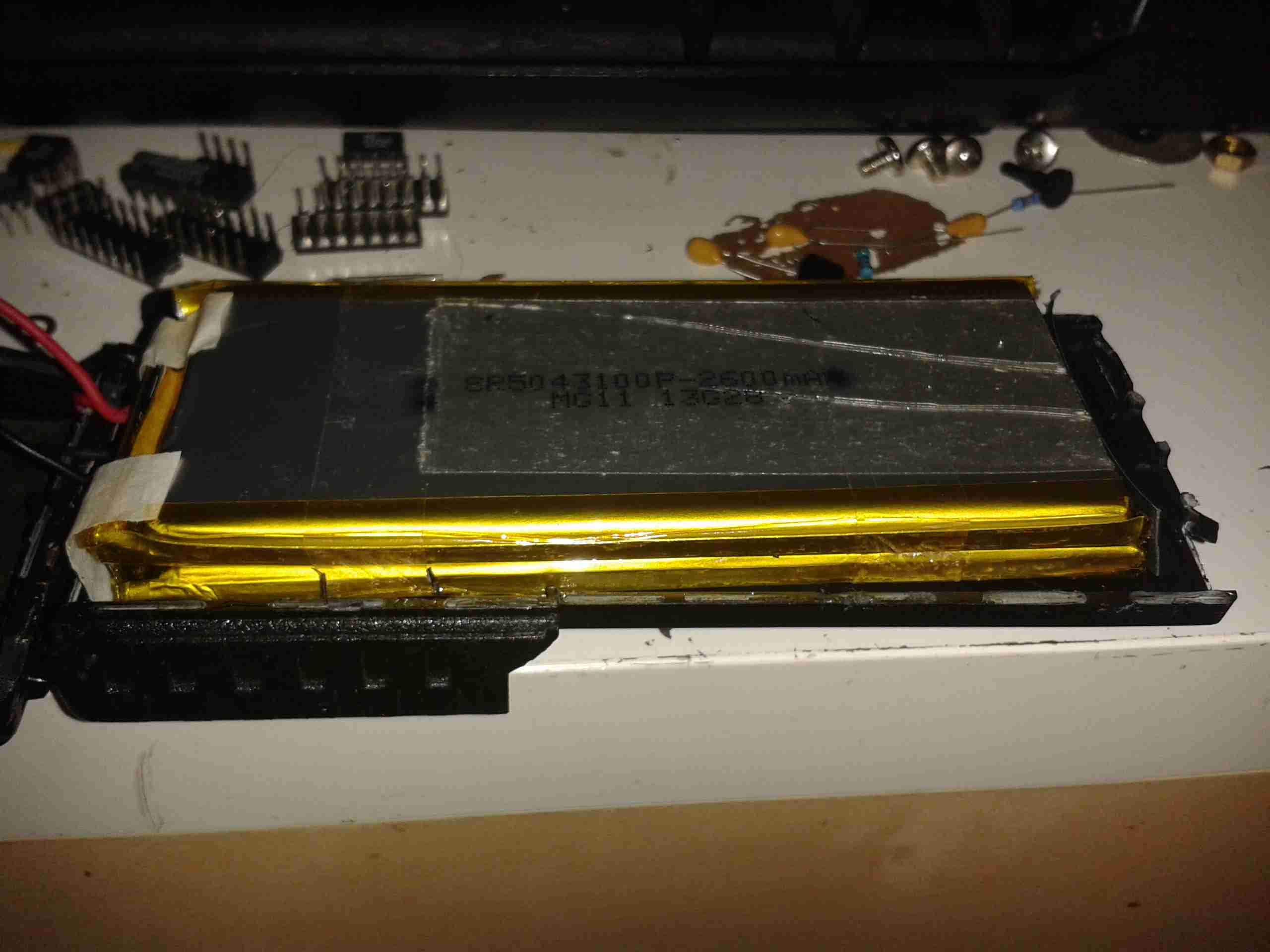
Cells
Here’s the other half of the case, with the cells themselves. These are wired in series for a 7.2v pack, and at a capacity of 2600mAh (2.6Ah) printed on them, the label clearly lies about the capacity.
I really like the UV-82s, over the UV-5Rs I was originally using, so I’ve bought another pair. Here are the power levels on test. Tests were done with a full battery charge on the 2m/70cm calling frequencies.
I recently dug out my other card printer to fit it with a 12v regulator, (it’s 24v at the moment), and figured I’d do a teardown post while I had the thing in bits.
This is a less industrial unit than my Zebra P330i, but unlike the Zebra, it has automatic duplexing, it doesn’t have Ethernet connectivity though.
Unlike domestic printers, which are built down to a price, these machines are very much built up to a spec, and feature some very high quality components.
Naked Printer
Here’s the mechanism with the cowling removed. This is the main drive side of the printer, with the main drive stepper at left, ribbon take-up spool motor lower right, and the duplex module stepper motors at far right.
Main Motor Drive
The main drive motor runs the various rollers in the card path through a pair of synchronous belts, shown here.
Main Stepper
The stepper itself is a quality ball-bearing Sanyo Denki bipolar motor.
Main Stepper Driver
Electrical drive is provided to the stepper with a L6258EX DMOS universal motor driver. This chip can also drive DC motors as well as steppers.
Ribbon Supply Spool
Here is the encoder geared onto the ribbon supply spool. This is used to monitor the speed the ribbon is moving relative to the card.
Printer Top
Here’s a top view through the printer, the blue roller on the left cleans the card as it’s pulled from the feeder, the gold coloured spool to it’s right is the ribbon supply reel. The cooling fan on the right serves to stop the print head overheating during heavy use.
Spool Take Up Motor
The spool take-up reel is powered by another very high quality motor, a Buhler DC gearmotor. These printers are very heavily over engineered!
This motor drives the spool through an O-Ring belt, before the gear above. This allows the drive to slip in the event the ribbon jams, preventing it from breaking.
Duplex Unit Stepper Drivers
The pair of steppers that operate the duplexing unit are driven by a separate board, with a pair of L6219DS bipolar stepper driver ICs. There are also a couple of opto-sensors on this board for the output hopper.
Main Control PCB
All the mechanisms of the printer are controlled from this main PCB, which handles all logic & power supply functions. Sections on the board are unpopulated, these would be for the Ethernet interface, smart card programming & magstripe programming.
Main CPU
The brains of the operation is this ColdFire MCF5208CVM166 32-bit microprocessor. It features 16KB of RAM, 8KB of cache, DMA controller, 3 UARTs, SPI, 10/100M Ethernet and low power management. This is a fairly powerful processor, running at 166MHz.
It’s paired with an external 128Mbit SDRAM from Samsung, and a Spansion 8Mbit boot sector flash, for firmware storage.
USB Interface & Power Input
Here the USB interface IC is located. It’s a USBN9604 from Texas Instruments, this interfaces with the main CPU via serial.
One bit of my equipment that I’ve never looked into is my scanner, a handheld Uniden unit. I got this when Maplin Electronics had them on special offer a few years ago.
Uniden Scanner
Here’s the scanner itself, roughly the same size as a usual HT.
Back Cover Removed
Here the back cover has been removed, and the main RF board is visible at the top of the stack. Unfortunately the shielding cans are soldered on this unit, so no looking under there 🙁
On the right hand side of the board next to the antenna input is the main RF filter network, and it’s associated switching. The RF front end is under the shield closest to the front edge.
Controls & 3.3v Regulator
On the other side of the PCB is the Volume & Squelch potentiometers, along with a dedicated 3.3v switching supply. An NJM2360A High Precision DC/DC converter IC controls this one. A 3.3v test point is visible next to the regulator.
RF Board Reverse
Here’s the backside of the RF board, some more interesting parts here. There’s a pair of NJM3404A Single Supply Dual Op-Amp ICs, and a TK10931V Dual AM/FM IF Discriminator IC. This is the one that does all the back-end radio functionality. The audio amplifier for the internal speaker & external headphone jack is also on this PCB, top left. A board-to-board interconnect links this radio board with the main control board underneath.
Control PCB Front
Here’s the front of the control PCB, nothing much to see here, just the LCD & membrane keypad contacts.
Control PCB Reverse
And here’s the reverse side of the control board. All the interesting bits are here. The main microcontroller is on the right, a Renesas M38D59GF, a fairly powerful MCU, with onboard LCD drive, A/D converter, serial interface, 60K of ROM & 2K of RAM. It’s 6.143MHz clock crystal is just below it.
The mating connector for the RF board is in the centre here.
There is also a Microchip 24LC168 16KB I²C EEPROM next to the main microcontroller. This is probably for storing user settings, frequencies, etc.
EEPROM
The rest of this board is dedicated to battery charging and power supply, in the centre is a dual switching controller, I can’t figure out the numbers on the tiny SOT23 components in here, but this is dealing with the DC 6v input & to the left of that is the circuitry for charging the NiMH cells included with the scanner.
PSU
The last bit of this PCB is a BU2092FV Serial In / Parallel Out 4 channel driver. Not sure what this one is doing, it might be doing some signal multiplexing for the RF board interface. Unfortunately the tracks from this IC are routed on the inner layers of the board so they can’t be traced out.
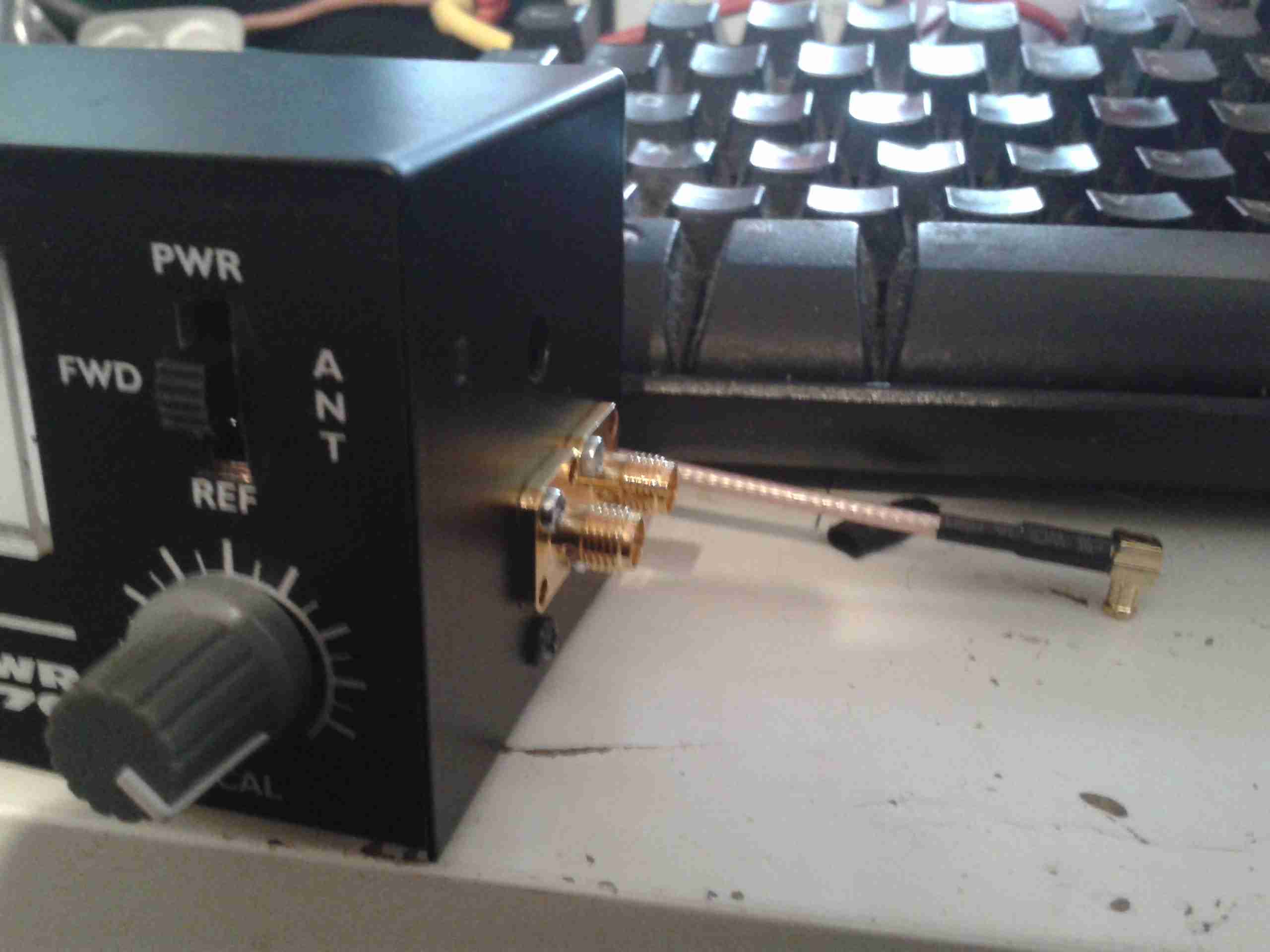
Now the final bits have arrived for the SWR Meter module, I can do the final assembly.
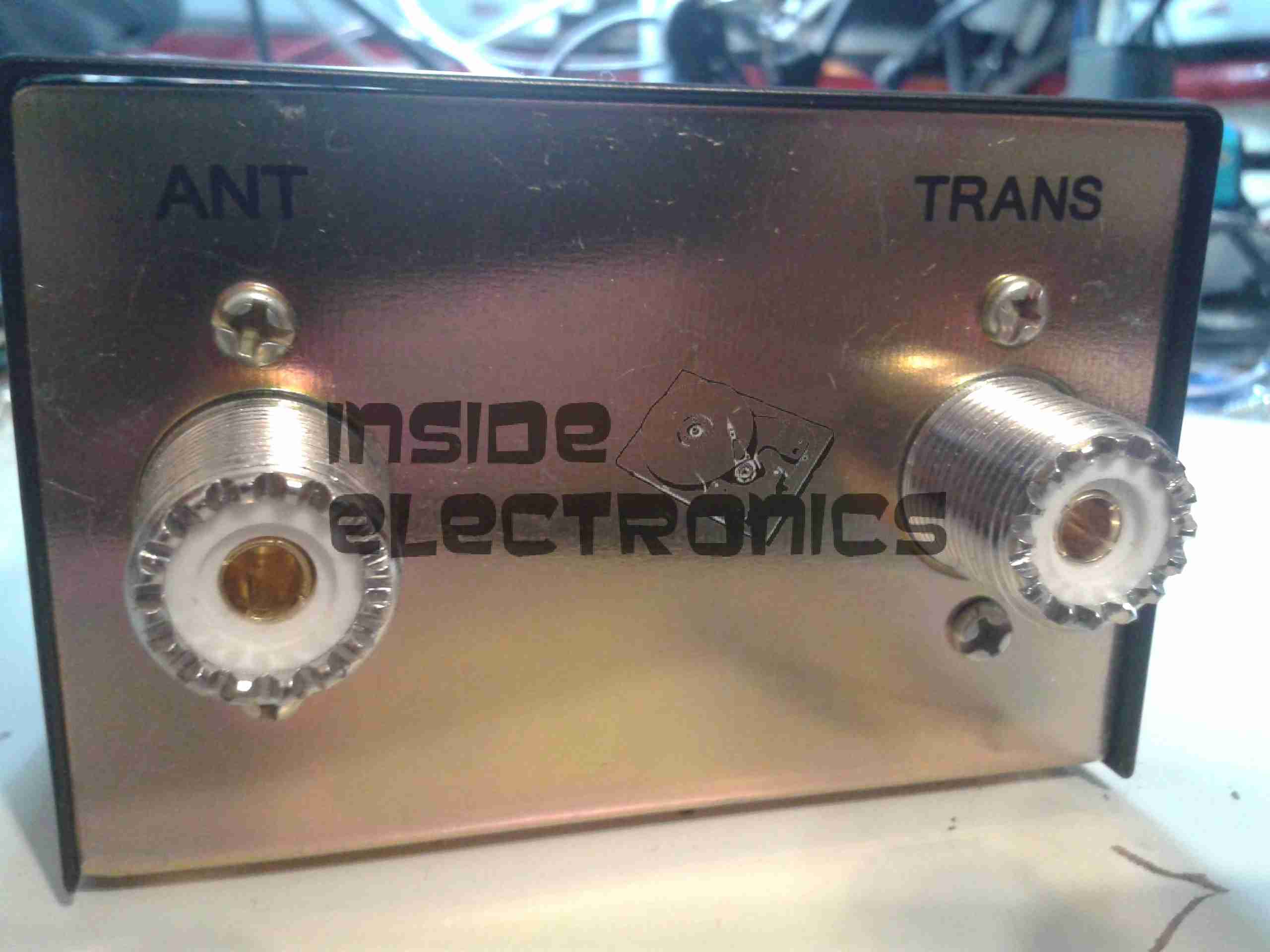
SMA Connectors
Here the SMA connectors are installed on the side of the eBay meter, for forward & reverse power tap.
These are simply tee’d off the wiring inside the meter where it connects to the switch.
Uncalibrated
The meter is connected to the module via a pair of RG58 SMA leads, above is a readout before calibration, using one of my Baofeng UV-5Rs.
I’m using my GY561 eBay Power Meter as a calibration source, and as this isn’t perfect, the readings will be slightly off. If I can get my hands on an accurate power meter & dummy load I can always recalibrate.
Tools are only as accurate as the standard they were calibrated from!
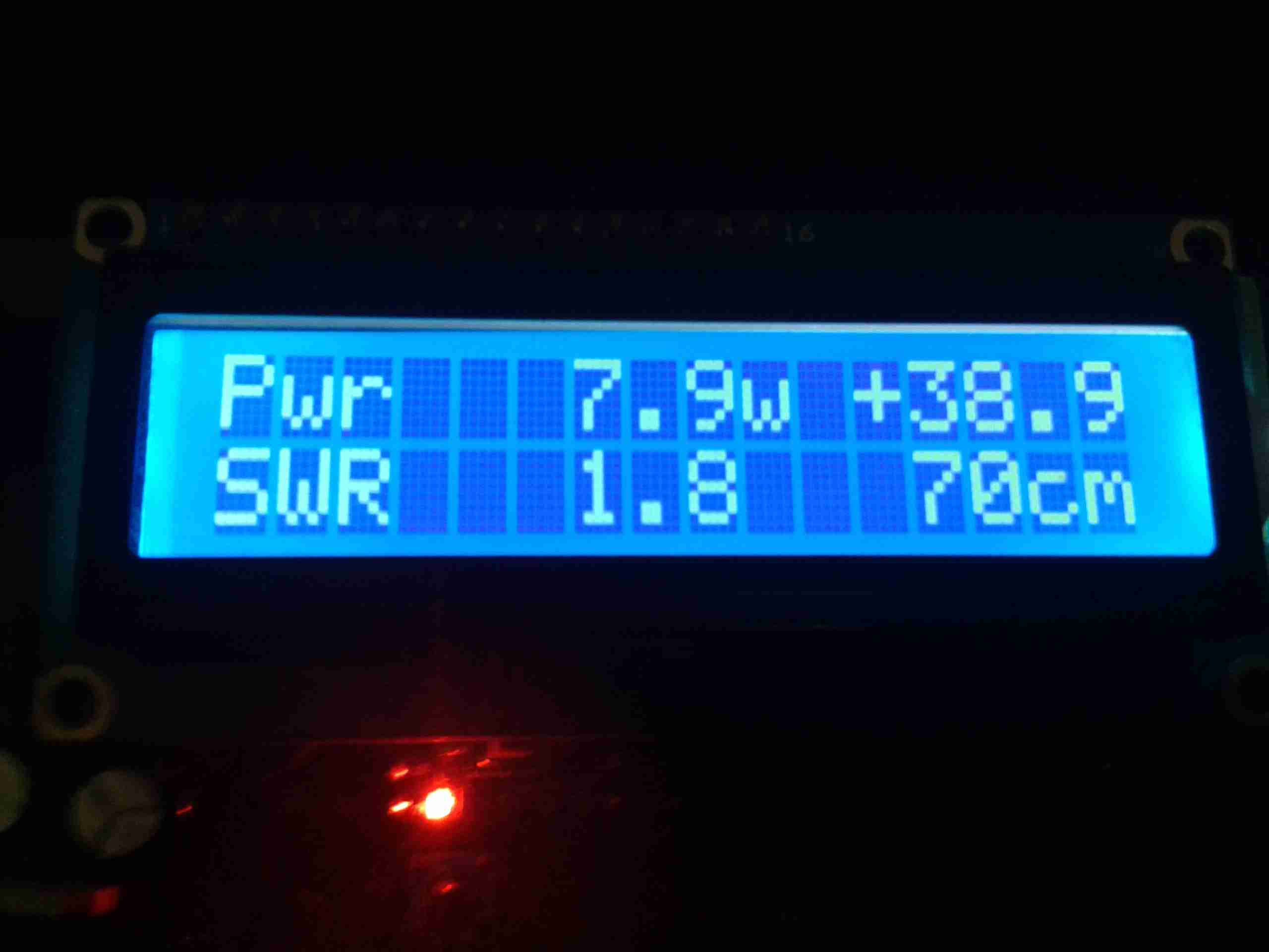
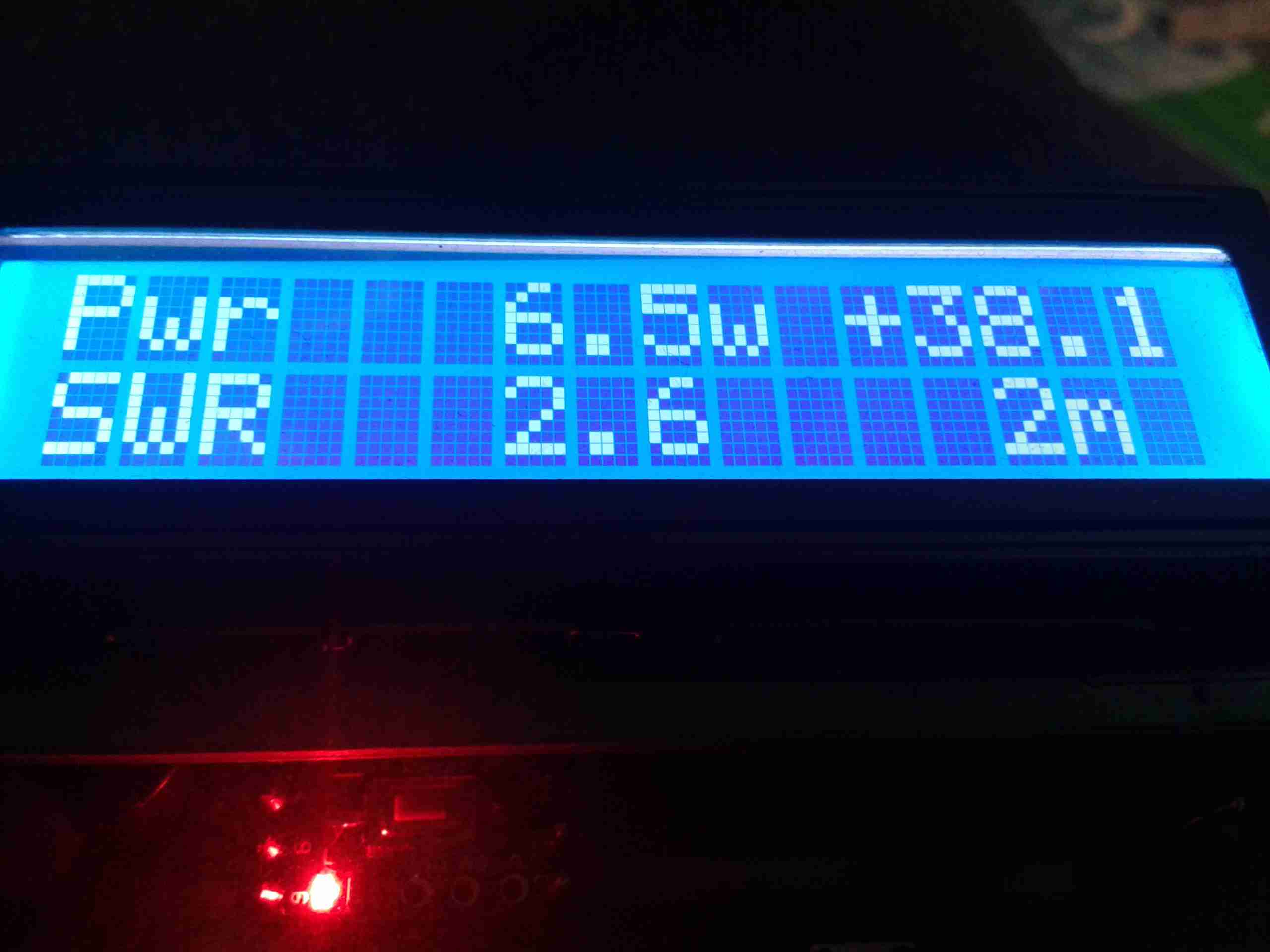
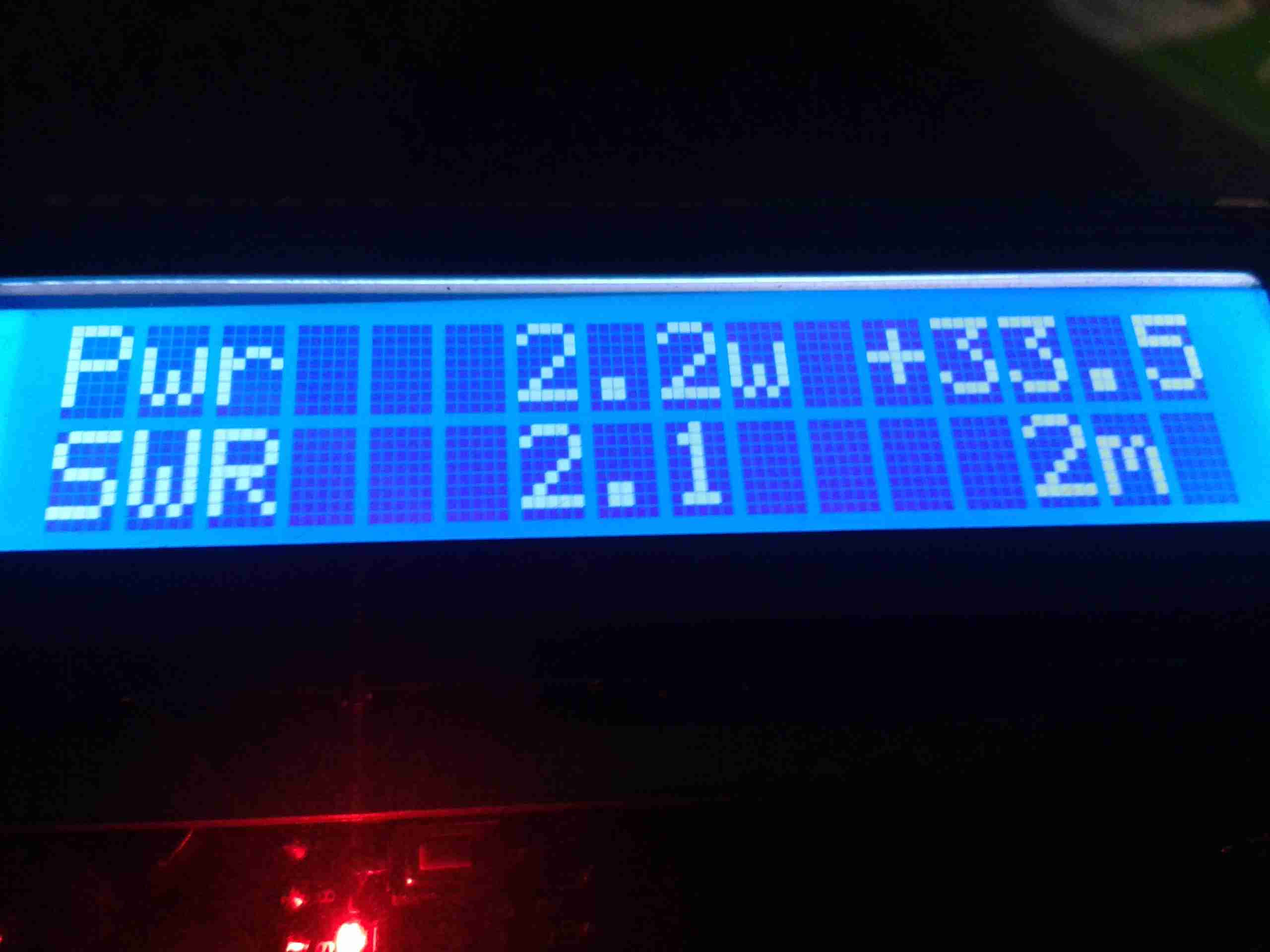
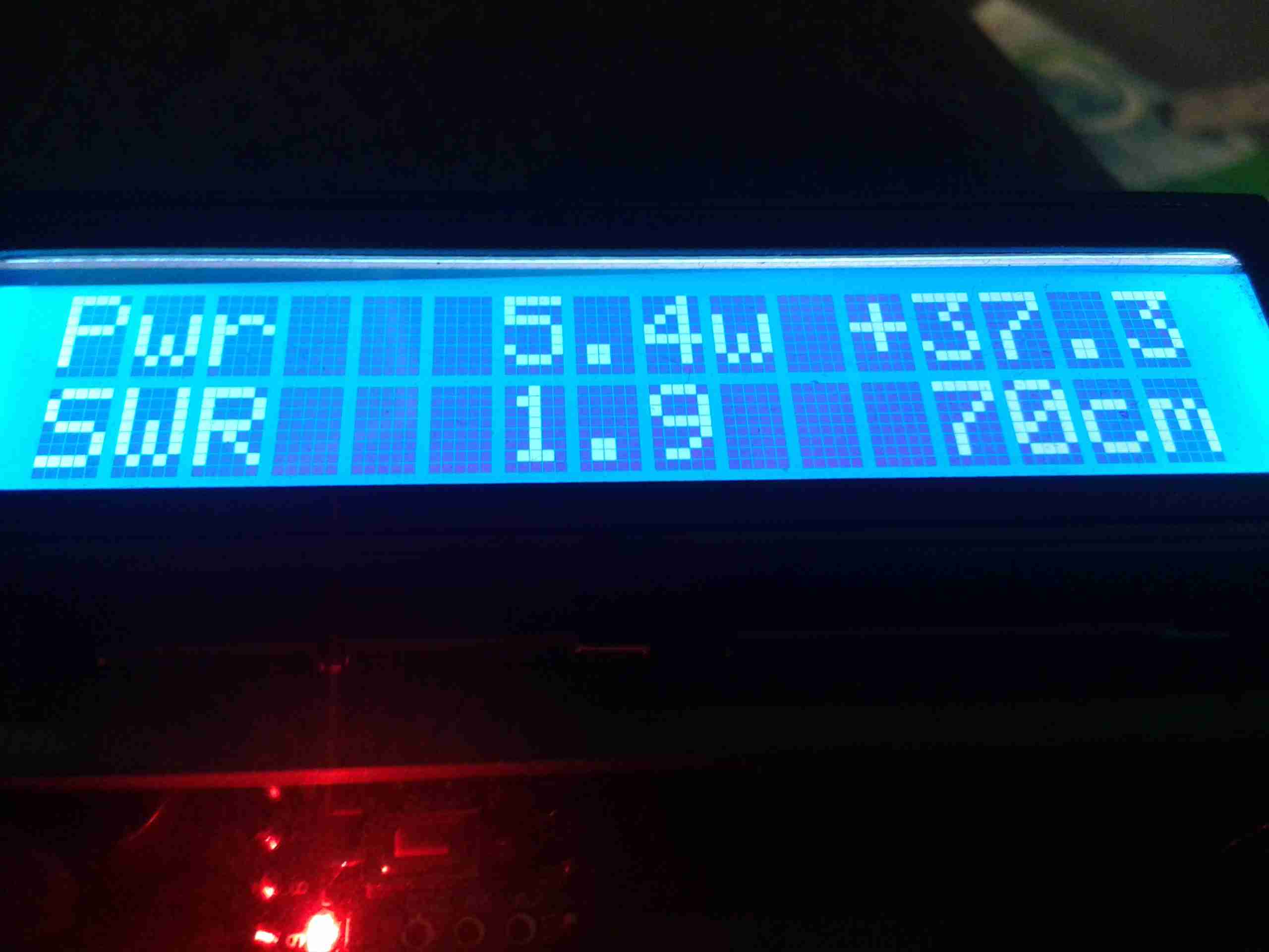
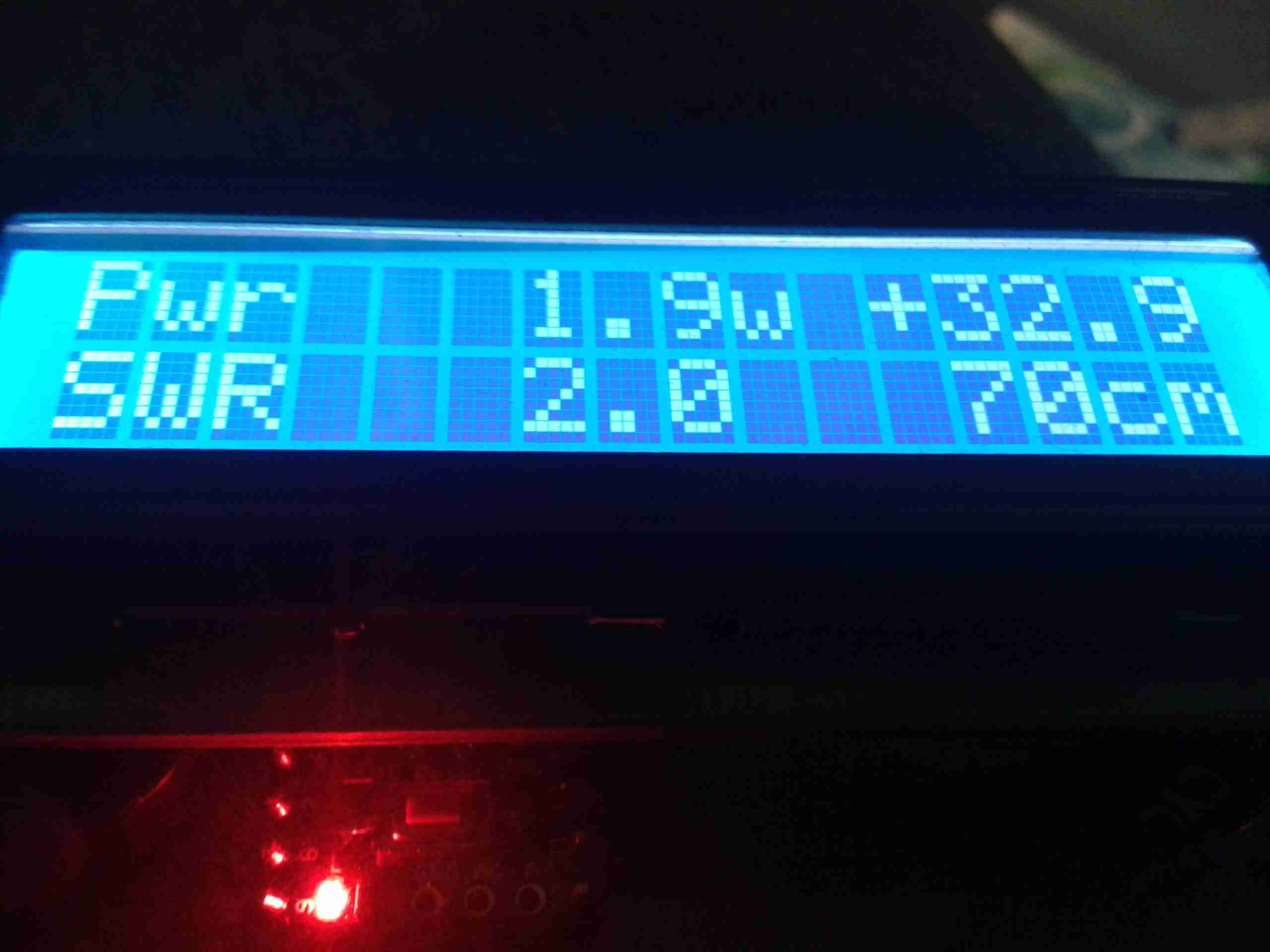
After calibration, here’s the readings on 2m & 70cm. These readings coincide nicely with the readings the GY561 produce, to within a couple tenths of a watt. SWR is more than 1:1 as the dummy load in the GY561 isn’t exactly 50Ω.
High Power VHFLow Power VHFHigh Power UHFLow Power UHF
Shortly I’ll calibrate against 6m & 10m so I can use it on every band I have access to 🙂
Here’s a quick look at a Sainsmart frequency counter module. These are useful little gadgets, showing the locked frequency on a small LCD display.
It’s built around an ATMega328 microcontroller (µC), and an MB501L Prescaler IC. The circuit for this is very simple, and is easily traced out from the board.
Frequency Counter
Here’s the back of the board, with the µC on the left & the prescaler IC on the right. This uses a rather novel method for calibration, which is the trimmer capacitor next to the crystal. This trimmer varies the frequency of the µC’s oscillator, affecting the calibration.
Input protection is provided by a pair of 1N4148 diodes in inverse parallel. These will clamp the input to +/-1v.
The prescaler IC is set to 1/64 divide ratio. This means that for an input frequency of 433MHz, it will output a frequency of 6.765625MHz to the µC.
The software in the µC will then calculate the input frequency from this intermediate frequency. This is done because the ATMega controllers aren’t very cabable of measuring such high frequencies.
The calculated frequency is then displayed on the LCD. This is a standard HD44780 display module.
LCD
Power is provided by a 9v PP3 battery, which is then regulated down by a standard LM7805 linear regulator.
Readout
I’ve found it’s not very accurate at all at the lower frequencies, when I fed it 40MHz from a signal generator it displayed a frequency of around 74MHz. This is probably due to the prescaler & the software not being configured for such a low input. In the case for 40MHz input the scaled frequency would have been 625kHz.
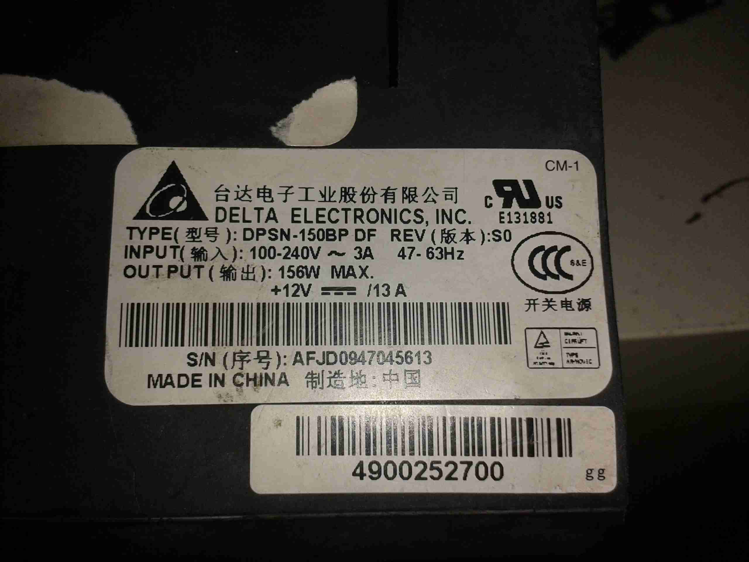
Recently I decommissioned some networking equipment, and discovered the power supplies in some switches were single rail 12v types, with a rather high power rating. I figured these would be very good for powering my Ham radio gear.
They’re high quality Delta Electronics DPSN-150BP units, rated at a maximum power output of 156W.
Label
These supplies have an adjustment pot for the output voltage regulation, but unfortunately it just didn’t have quite enough range to get from 12.0v to 13.8v. The highest they would go was ~13.04v.
After taking a look at the regulator circuit, I discovered I could further adjust the output voltage by changing a single resistor to a slightly lower value.
Firstly though, a little background on how switched mode power supplies operate & regulate their output voltage.
SMPS
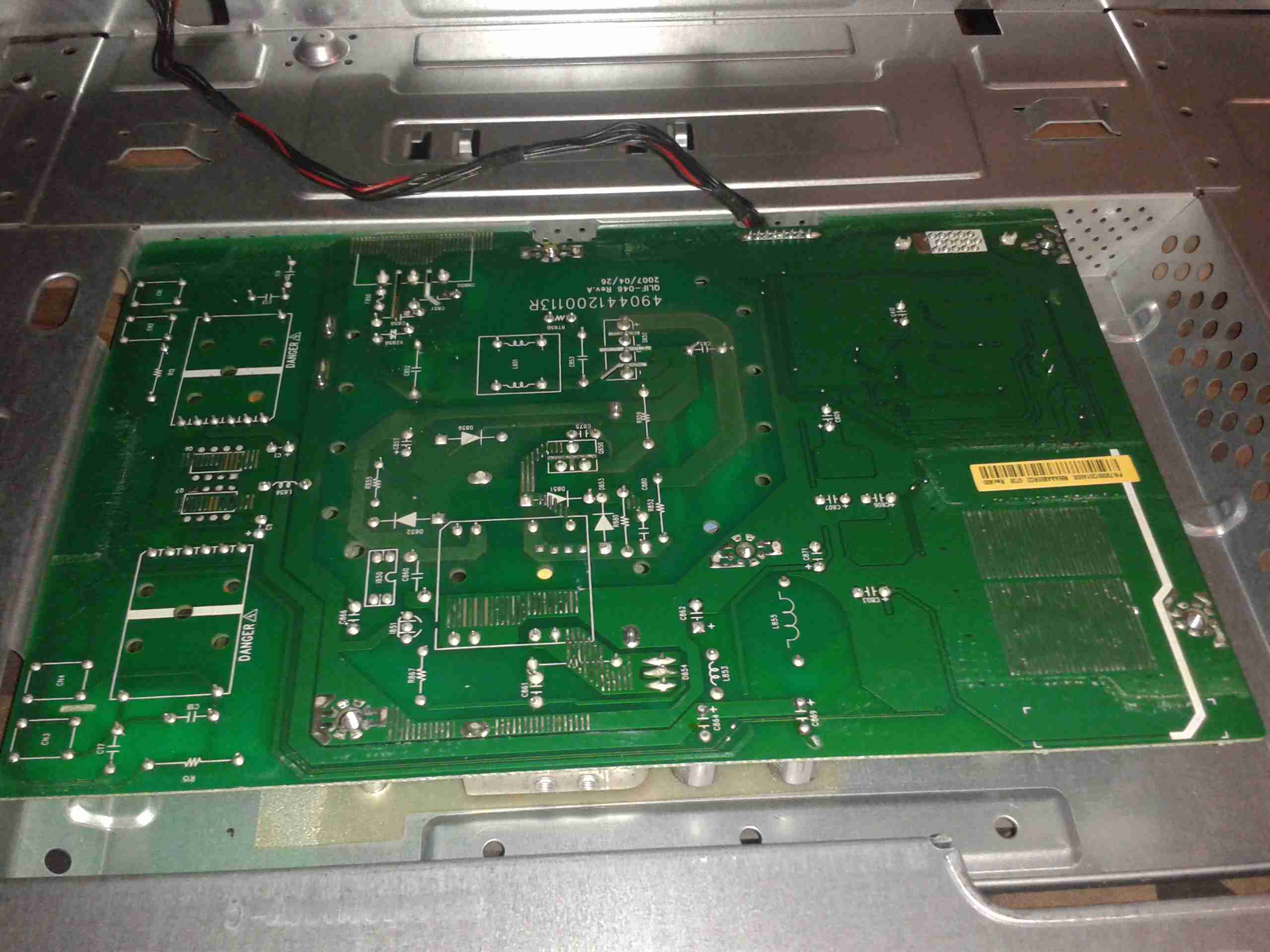
Here’s the supply. It’s mostly heatsink, to cool the large power switching transistors.
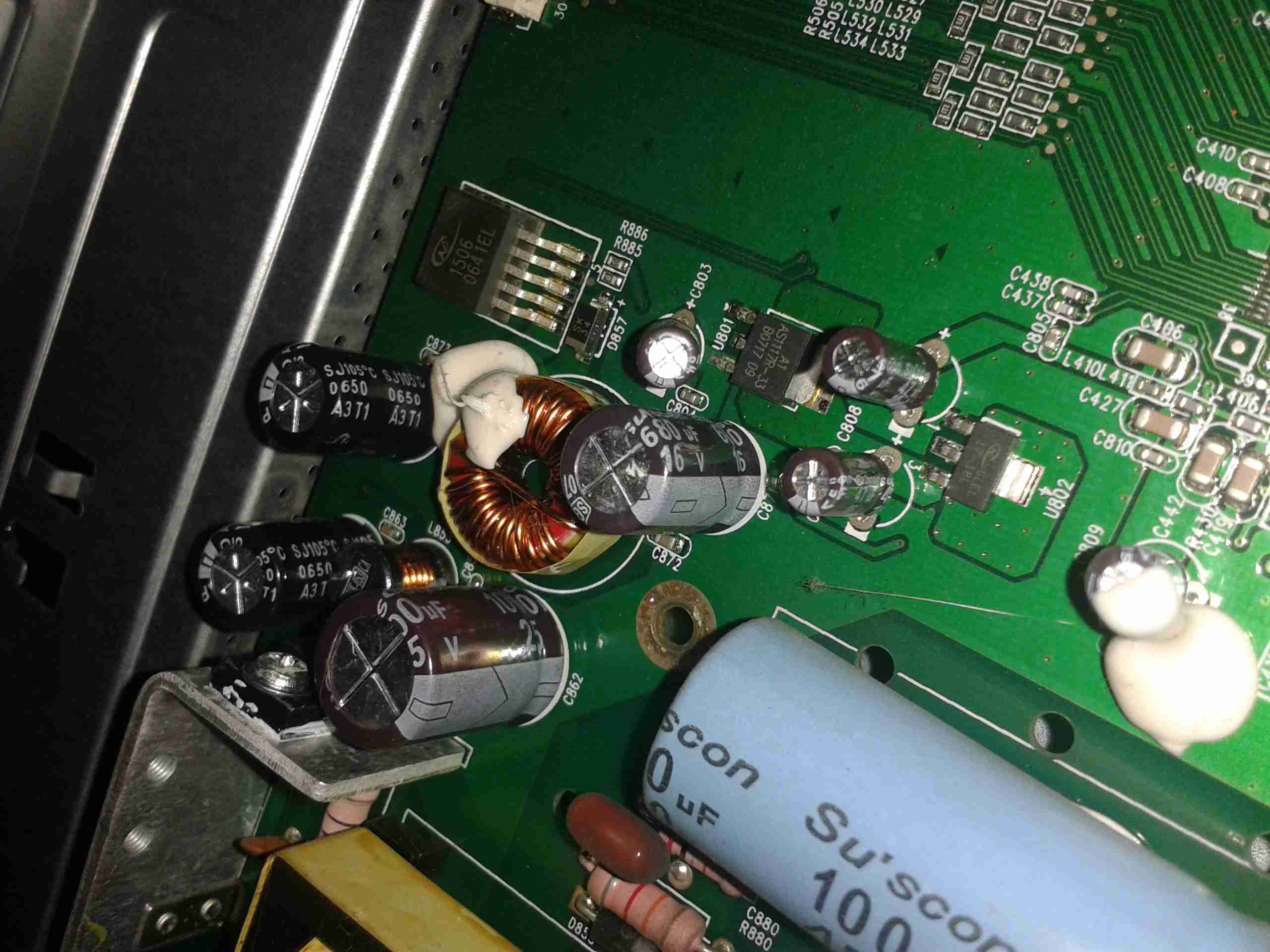
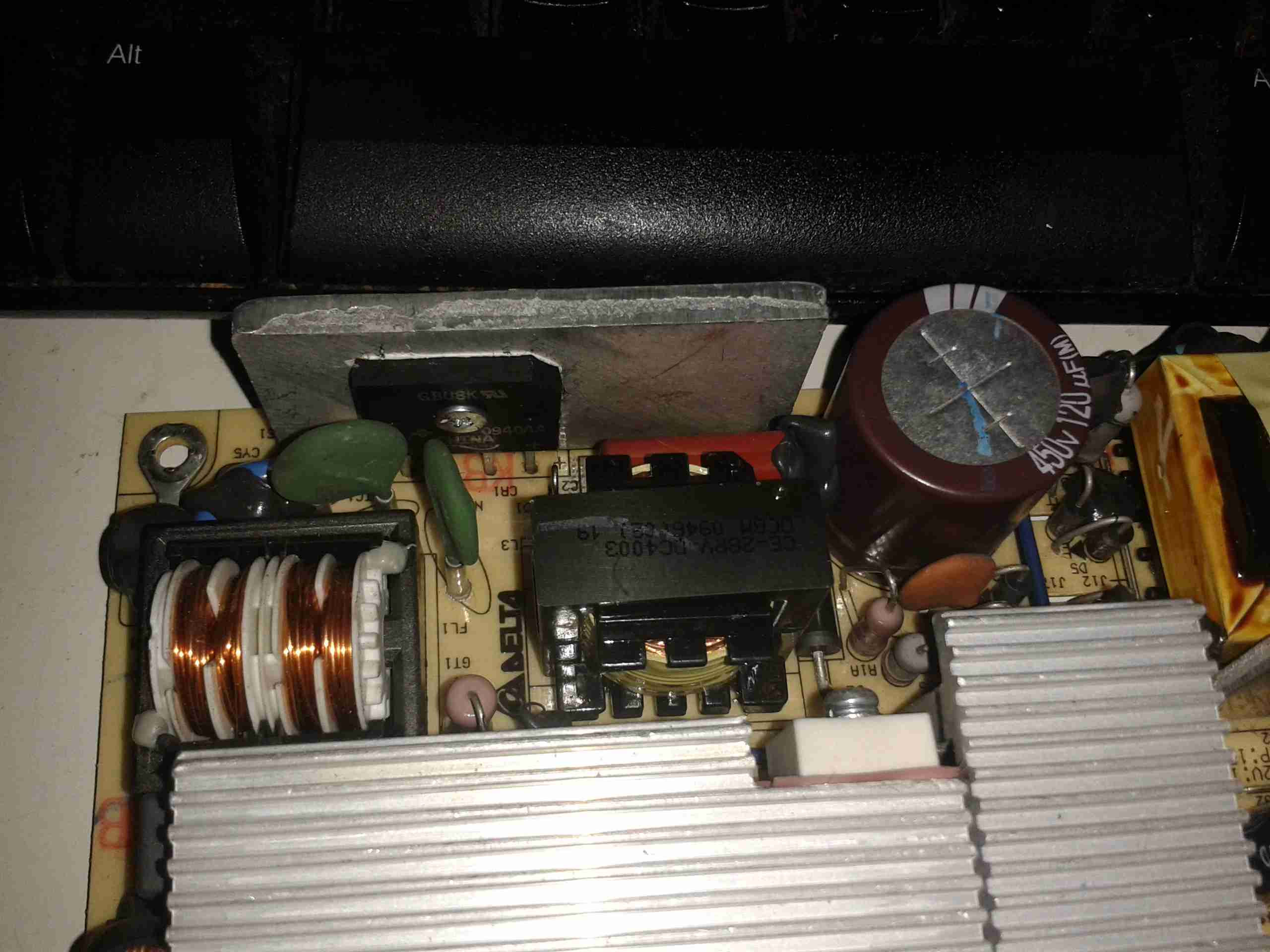
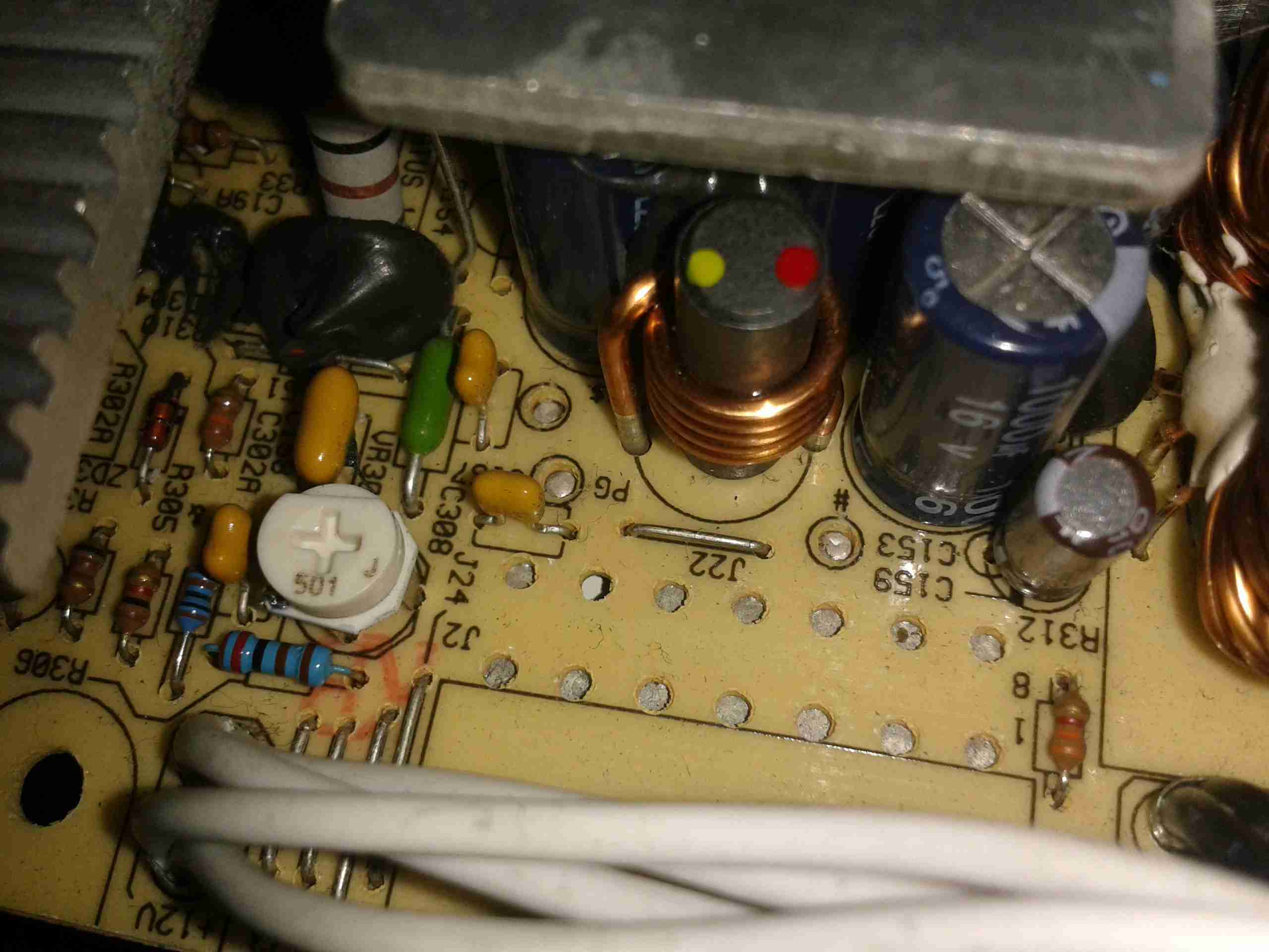
The first thing a SMPS does, is to rectify the incoming mains AC with a bridge rectifier. This is then smoothed by a large electrolytic capacitor, to provide a main DC rail of +340v DC (when on a 240v AC supply).
Mains Input
Above is the mains input section of the PSU, with a large common-mode choke on the left, bridge rectifier in the centre, and the large filter capacitor on the right. These can store a lot of energy when disconnected from the mains, and while they should have a discharge resistor fitted to safely drain the stored energy, they aren’t to be relied on for safety!
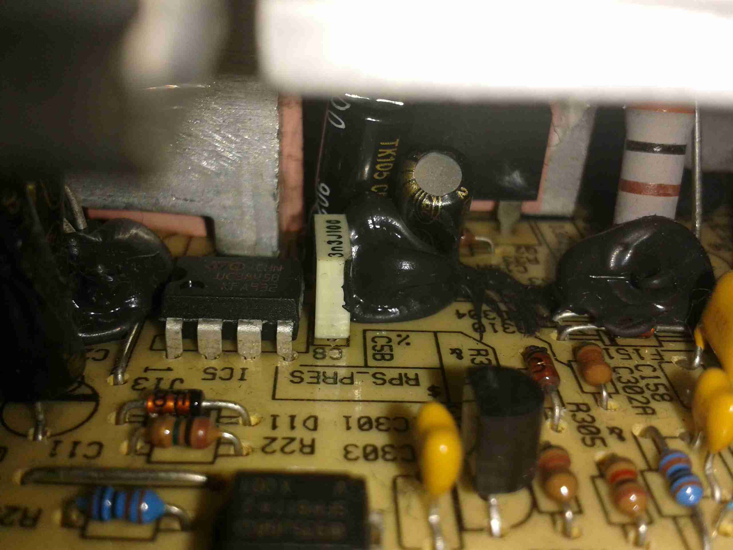
Once the supply has it’s main high voltage DC rail, this is switched into the main transformer by a pair of very large transistors – these are hidden from view on the large silver heatsinks at the bottom of the image. These transistors are themselves driven with a control IC, in the case of this supply, it’s a UC3844B. This IC is hidden under the large heatsink, but is just visible in the below photo. (IC5).
Control ICMain Switching Transformer
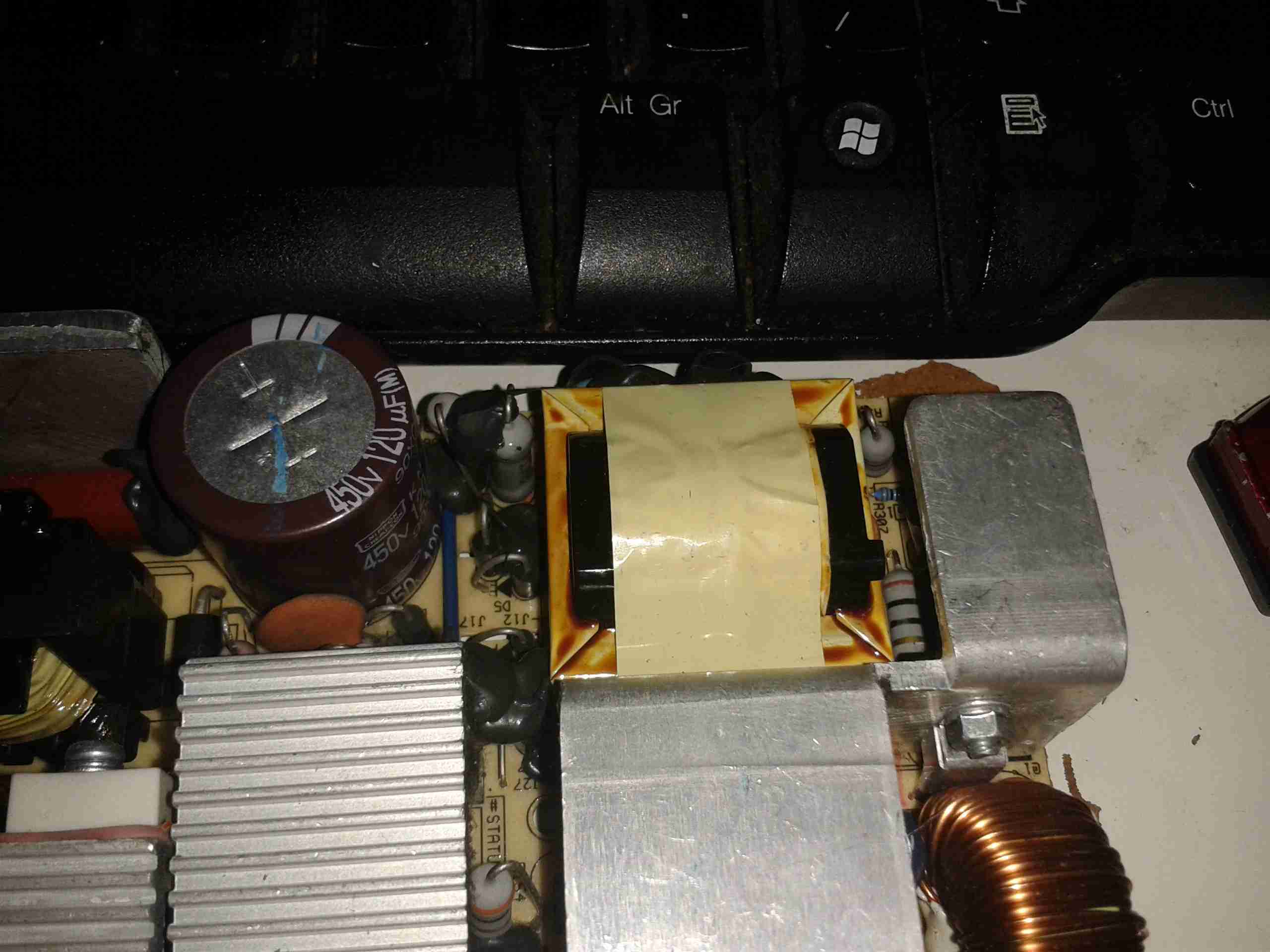
Here’s the main switching transformer, these can be much smaller than a conventional transformer due to the high frequencies used. This supply operates at 500kHz.
After the main transformer, the output is rectified by a pair of Schottky diodes, which are attached to the smaller heatsink visible below the transformer, before being fed through a large toroidal inductor & the output filter capacitors.
All this filtering on both the input & the output is required to stop these supplies from radiating their operating frequency as RF – a lot of cheap Chinese switching supplies forego this filtering & as a result are extremely noisy.
After all this filtering the DC appears at the output as usable power.
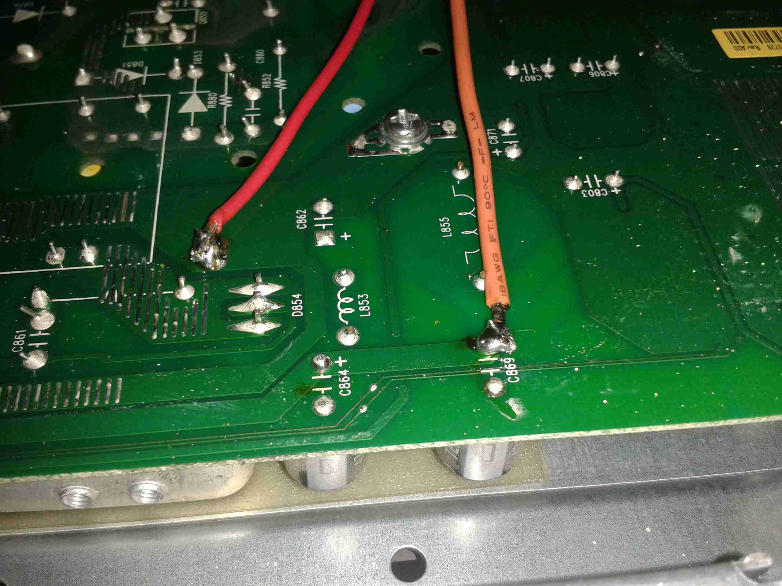
Getting back to regulation, these supplies read the voltage with a resistor divider & feed it back to the mains side control IC, through an opto-isolator. (Below).
Feedback Loop
The opto isolators are the black devices at the front with 4 pins.
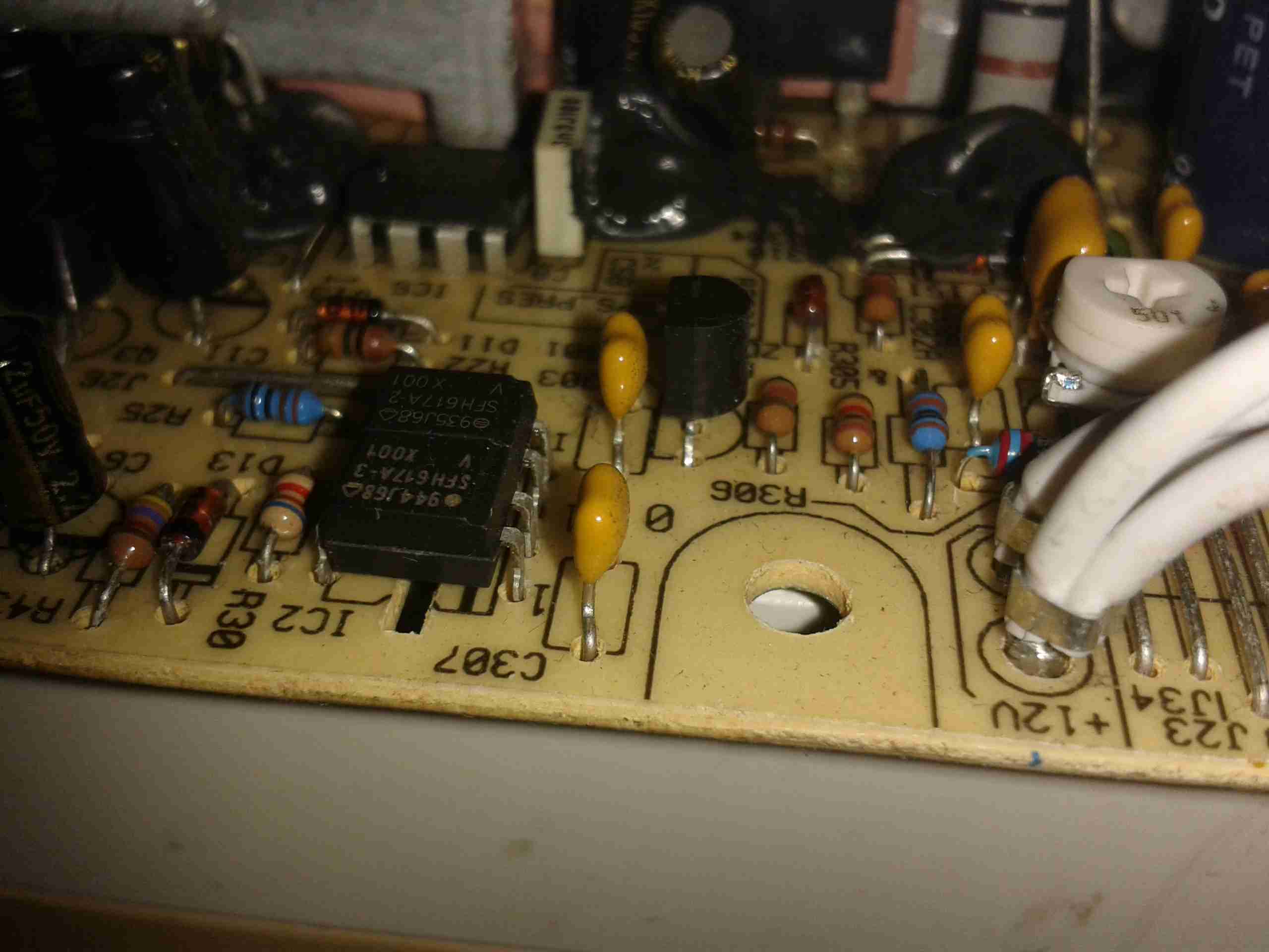
Regulator Adjustment
For a more in-depth look at the inner workings of SMPS units, there’s a good article over on Hardware Secrets.
My modification is simple. Replacing R306 (just below the white potentiometer in the photo), with a slightly smaller resistor value, of 2.2KΩ down from 2.37KΩ, allows the voltage to be pulled lower on the regulator. This fools the unit into applying more drive to the main transformer, and the output voltage rises.
It’s important to note that making too drastic a change to these supplies is likely to result in the output filter capacitors turning into grenades due to overvoltage. The very small change in value only allows the voltage to rise to 13.95v max on the adjuster. This is well within the rating of 16v on the output caps.
Now the voltage has been sucessfully modified, a new case is on the way to shield fingers from the mains. With the addition of a couple of panel meters & output terminals, these supplies will make great additions to my shack.
I recently posted about a small analog SWR/Power meter I got from eBay, and figured it needed some improvement.
After some web searching I located a project by ON7EQ, an Arduino sketch to read SWR & RF power from any SWR bridge.
The Arduino code is on the original author’s page above, his copyright restrictions forbid me to reproduce it here.
I have also noticed a small glitch in the code when it is flashed to a blank arduino: The display will show scrambled characters as if it has crashed. However pushing the buttons a few times & rebooting the Arduino seems to fix this. I think it’s related to the EEPROM being blank on a new Arduino board.
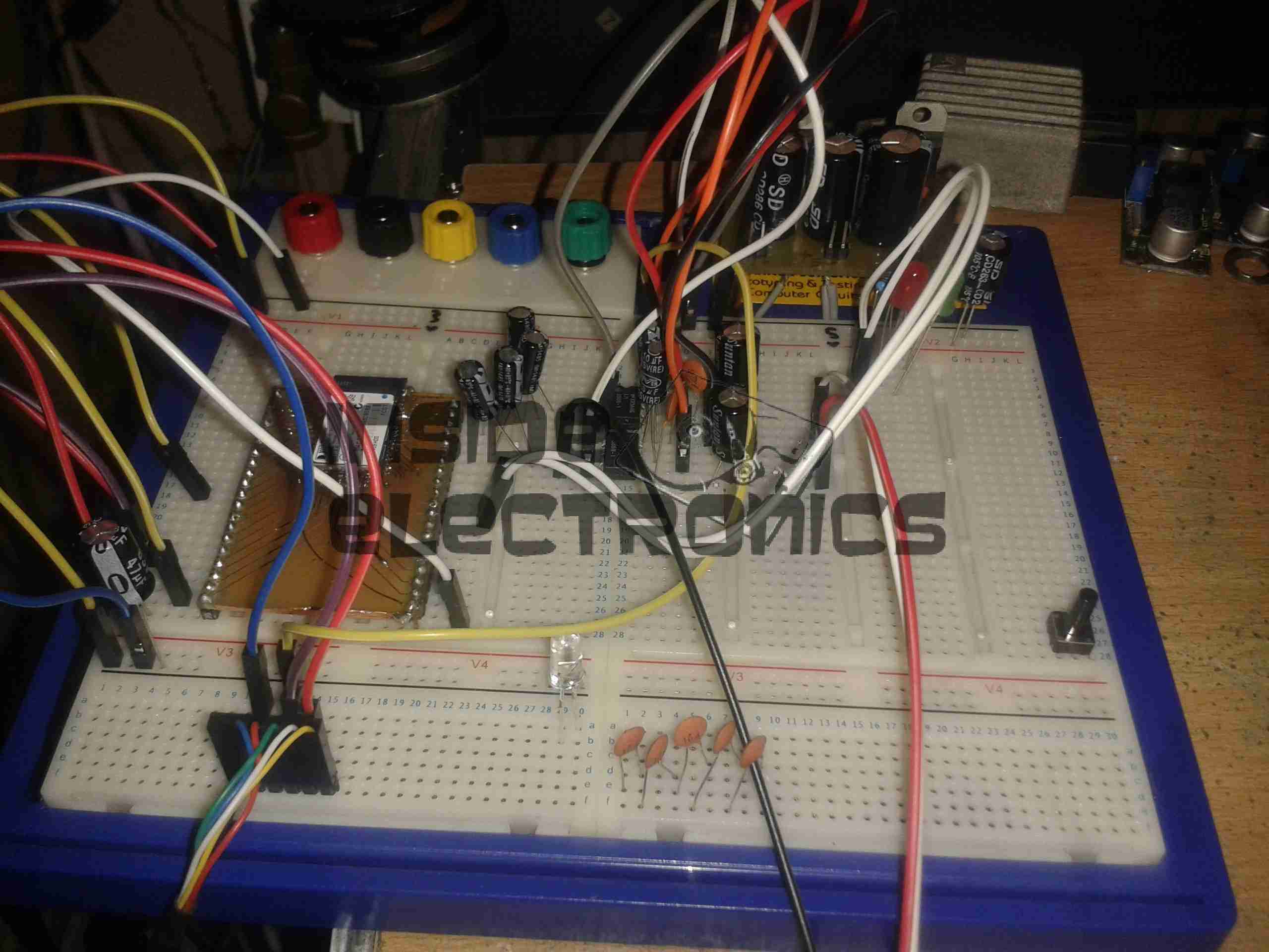
I have run a board up in Eagle for testing, shown below is the layout:
SWR Meter SCH
The Schematic is the same as is given on ON7EQ’s site. Update: ON7EQ has kindly let me know I’ve mixed up R6 & R7, so make sure they’re switched round when the board is built ;). Fitting the resistors the wrong way around may damage the µC with overvoltage.
SWR Meter PCB
Here’s the PCB layout. I’ve kept it as simple as possible with only a single link on the top side of the board.
PCB Top
Here’s the freshly completed PCB ready to rock. Arduino Pro mini sits in the center doing all the work.
The link over to A5 on the arduino can be seen here, this allows the code to detect the supply voltage, useful for battery operation.
On the right hand edge of the PCB are the pair of SMA connectors to interface with the SWR bridge. Some RF filtering is provided on the inputs.
PCB Bottom
Trackside view of the PCB. This was etched using my tweaked toner transfer method.
LCD Fitted
Here the board has it’s 16×2 LCD module.
Online
Board powered & working. Here it’s set to the 70cm band. The pair of buttons on the bottom edge of the board change bands & operating modes.
As usual, the Eagle layout files are available below, along with the libraries I use.
[download id=”5585″]
[download id=”5573″]
More to come on this when some components arrive to interface this board with the SWR bridge in the eBay meter.
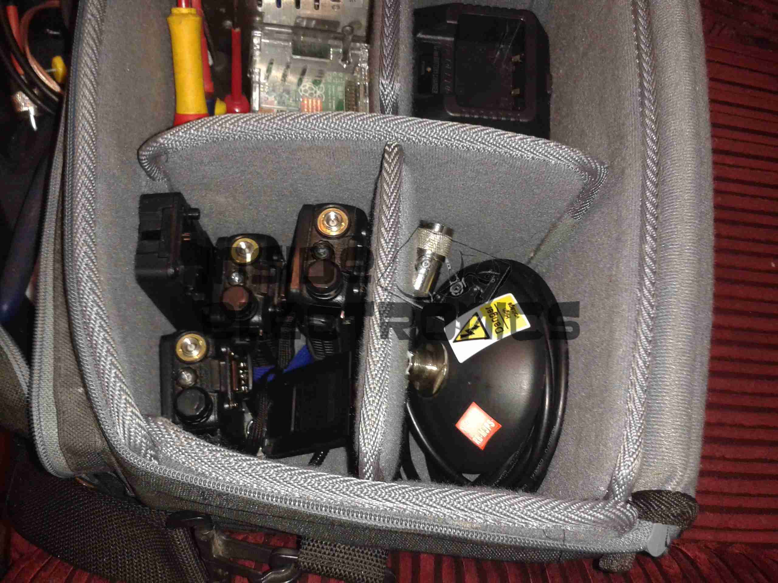
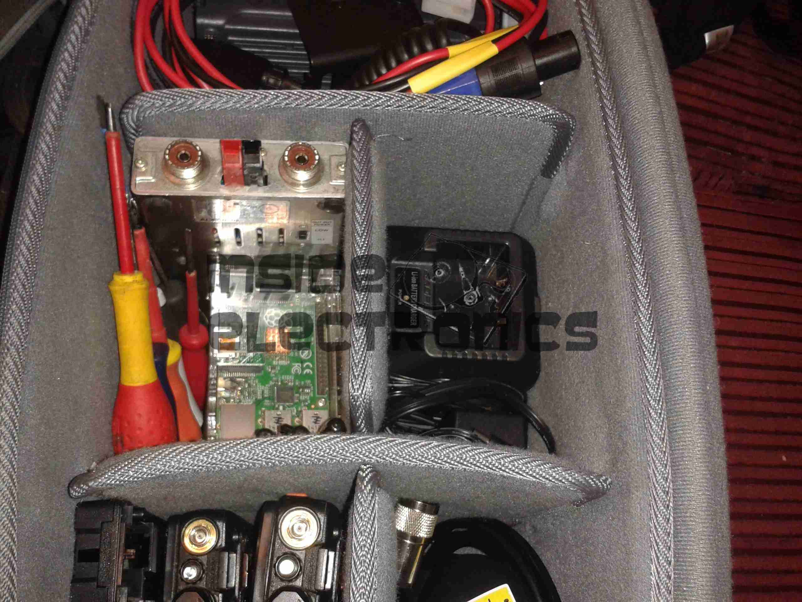
There are times when I am frequently away from home base, usually either on the canal system or at a festival. During these times it’s very handy to be able to just grab a bag, without having to be concerned about sorting everything out.
This post will only detail the portable shack bag. The power supply kit that goes along with it with be detailed in another post.
The bag I use is an VHS Camcorder bag from the early 80’s. It’s very well built, & copes easily with the weight of all the radio gear.
Total weight for this system is 13.4lbs (6kg).
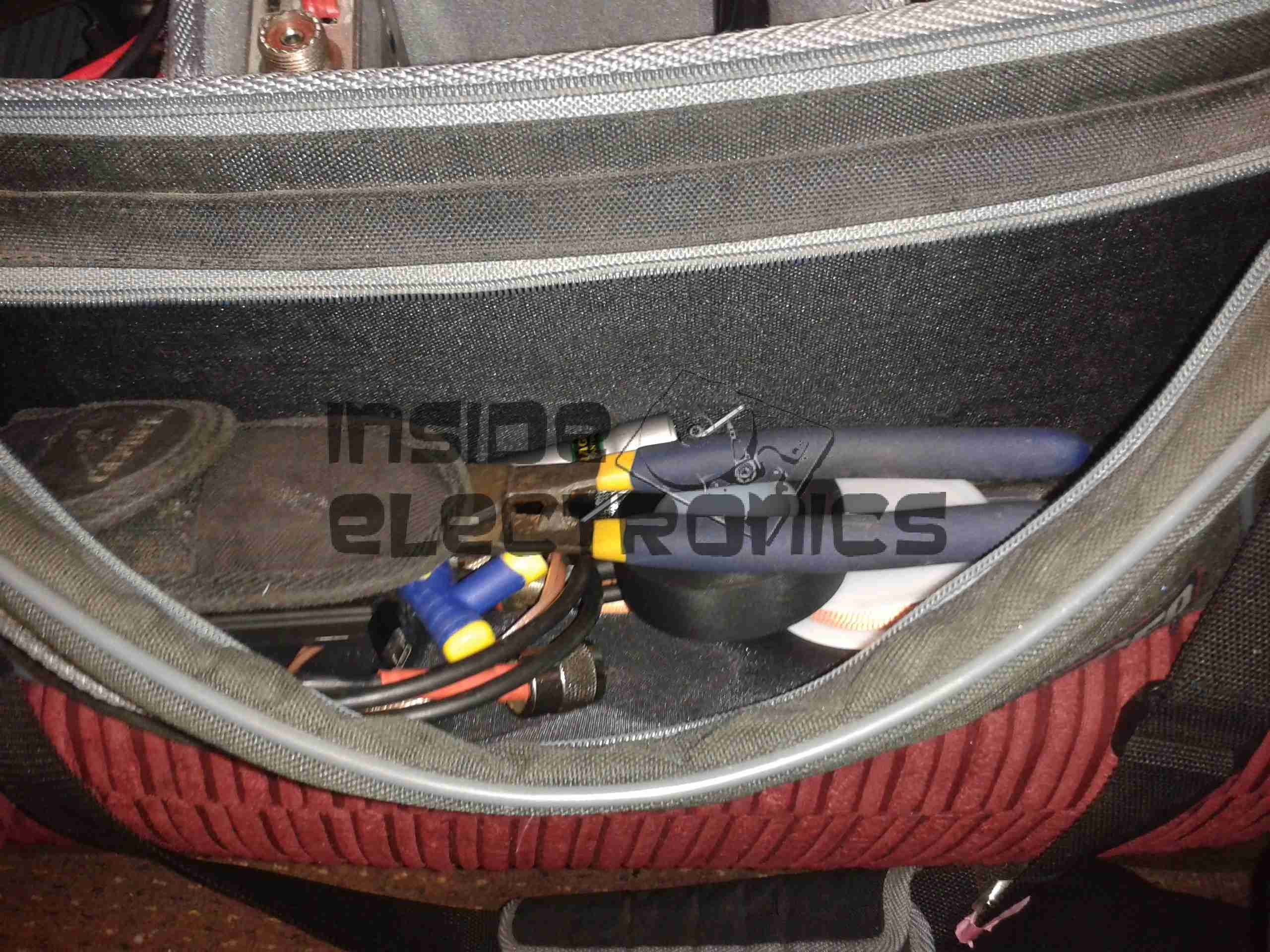
Mobile Radio Bag
Above is the bag packed. Obligatory International Ameteur Radio Symbol patch front & centre. Being an old camera bag, this easily slings over the shoulder, with it’s padded strap.
Current Equipment
Here is all the current equipment laid out. All the equipment to enable me to set up a station anywhere.
In the following photos I will go into the details.
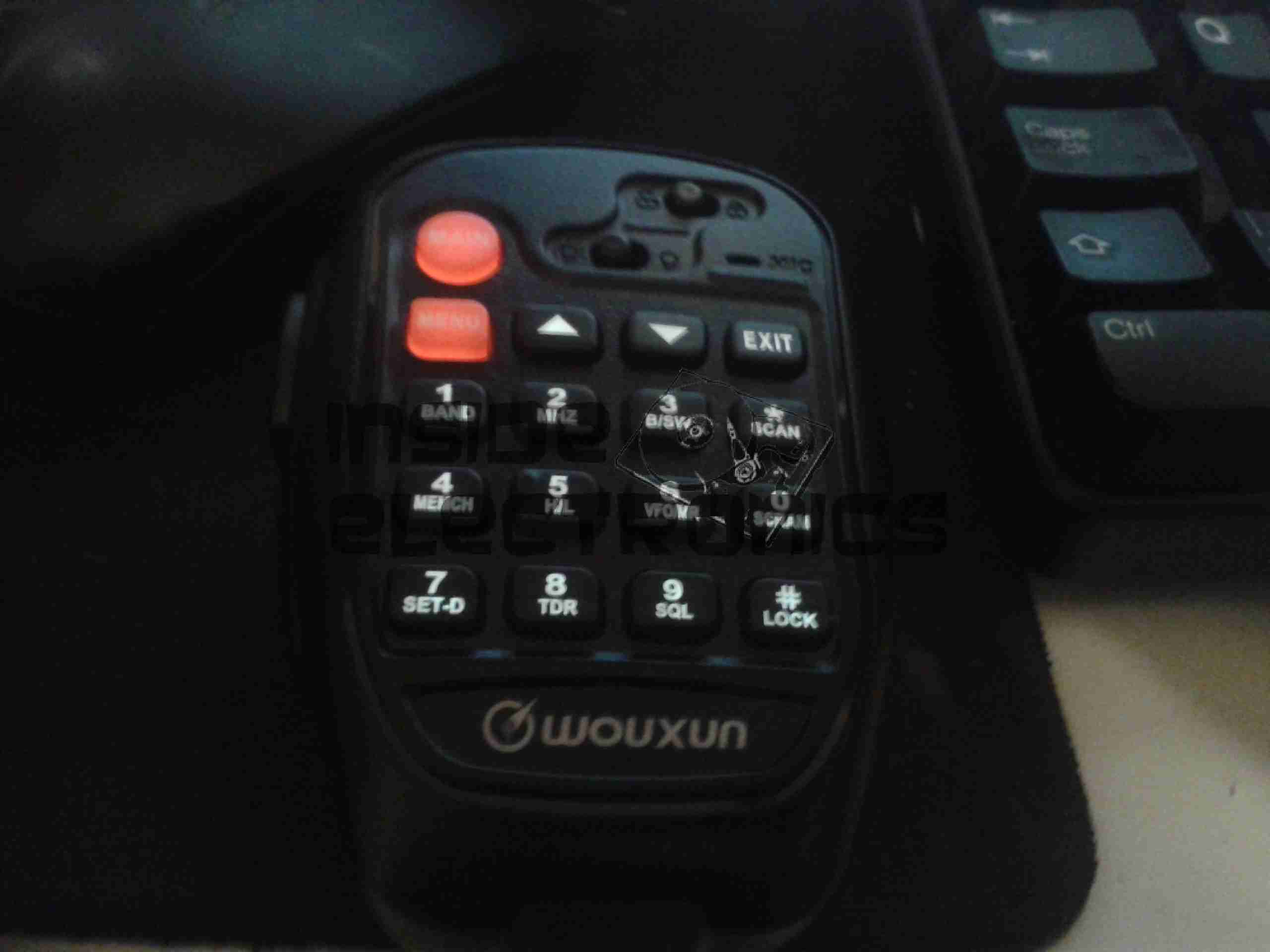
Main Radio
First off, my main radio. This is the same Wouxun KG-UV950P mobile rig I have posted about previously. I have heatshrunk the power cable to keep it together & attached my standard power connector to the end. More on these later on.
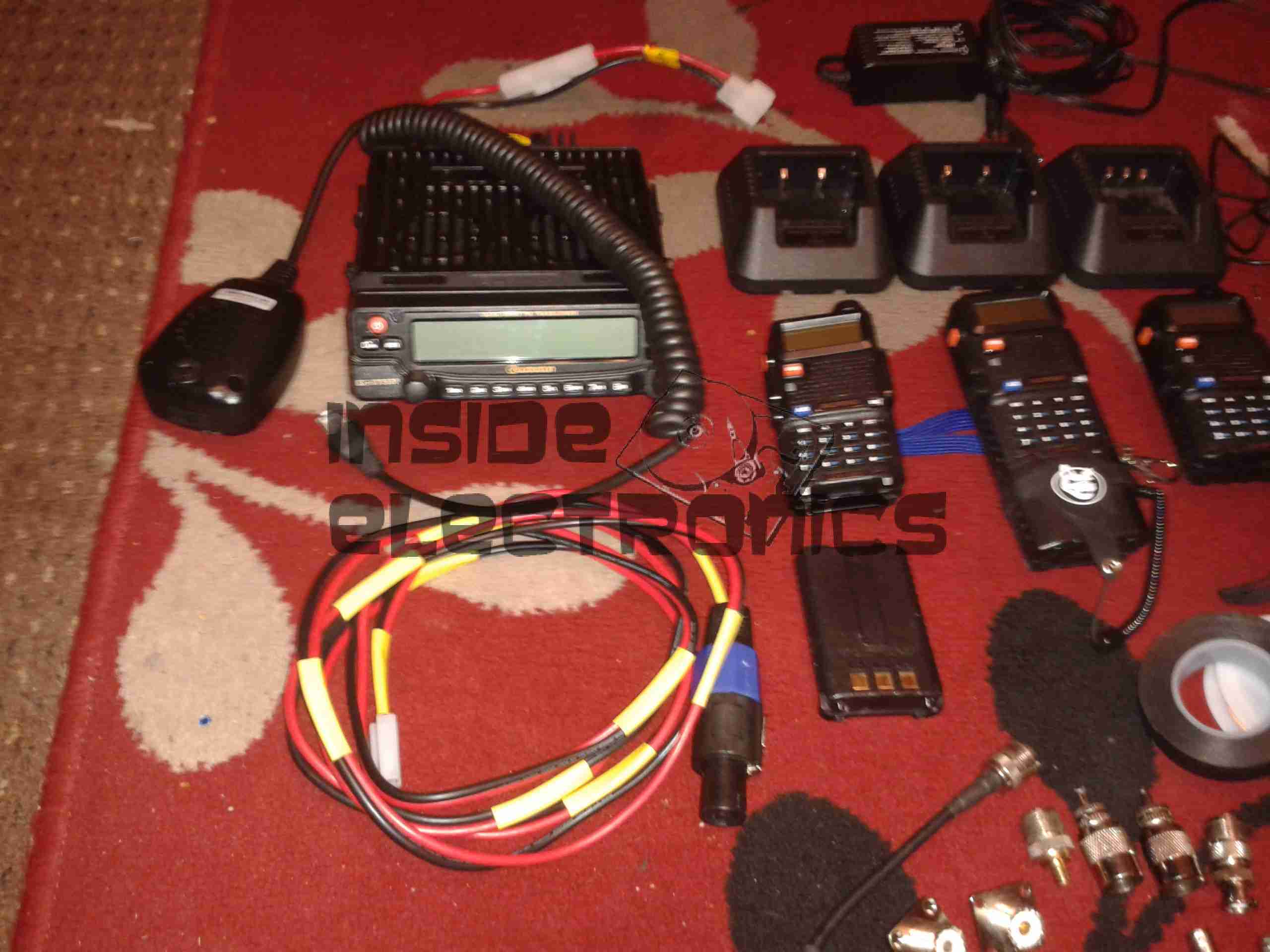
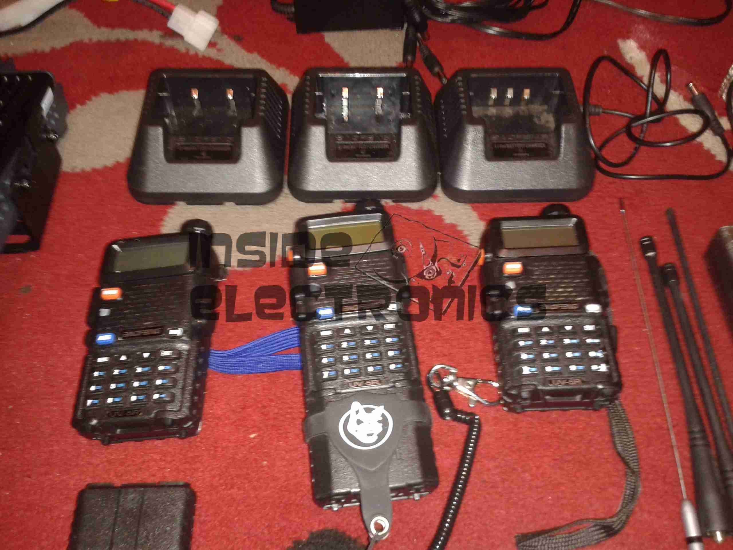
HTs
In the bag I also carry three Baofeng UV-5R handhelds. Extremely useful for short range site communications, along with their charger bases. The charging base on the right has been slightly modified to support charging of my main LED torch as well, which uses similar Li-Ion based packs as the Baofengs.
Baofeng 12v Charger
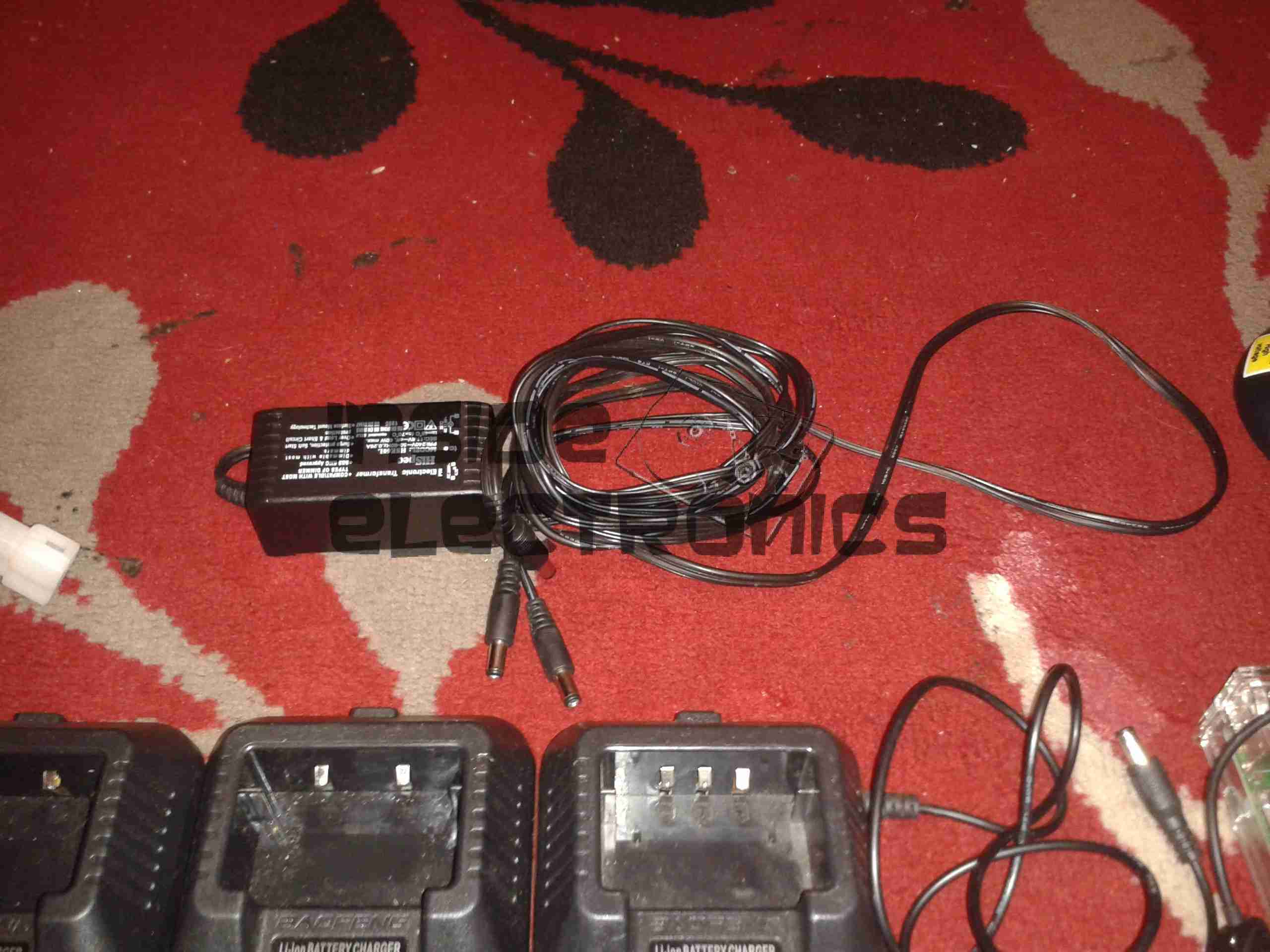
As the charger bases for the Baofeng HTs take a supply of 10v DC, I have constructed a 12v adaptor system for them. (Which utter prat of an engineer at Baofeng picked 10v?)
Linear Amplifier & SWR Meter
Also included is a small Alinco ELH-2320 35W 2m linear amplifier. This was given to me from the local HackSpace in Manchester. (They don’t have any ham members, besides myself). Also here is my small SWR & Power meter, SDR kit & a pair of syringes. These are filled respectively with Copaslip copper loaded grease, (very good for stopping fasteners exposed to the weather from seizing up), and dielectric silicone grease. (I use this stuff for filling connectors that are exposed to the weather – keeps the water out).
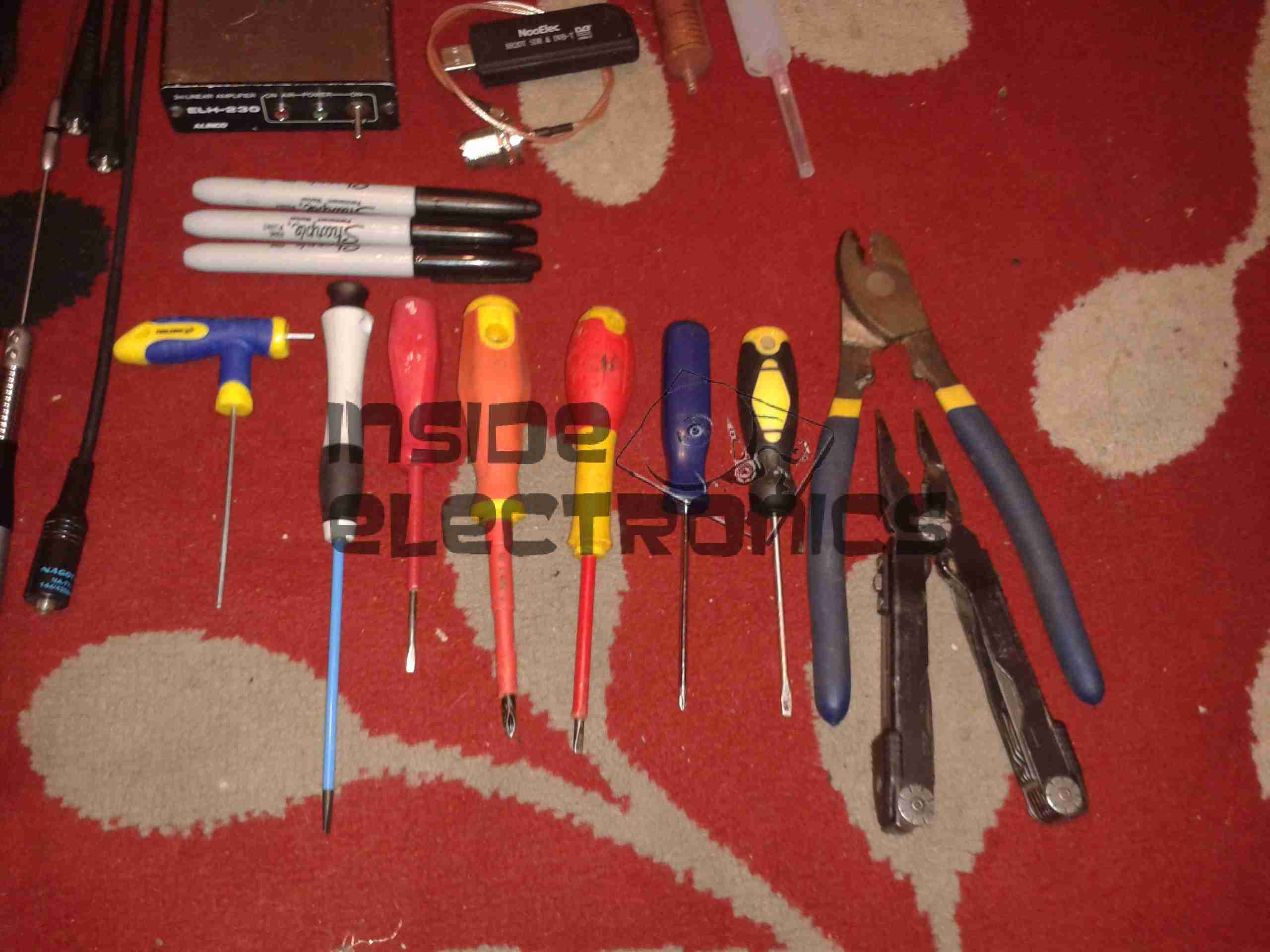
Tools
I always keep essential tools in the bag, here is the small selection of screwdrivers which fit pretty much any screw fastener around, my heavy-duty cable shears (these buggers can cut through starter cable in one go!) and my trusty Gerber Diesel multitool.
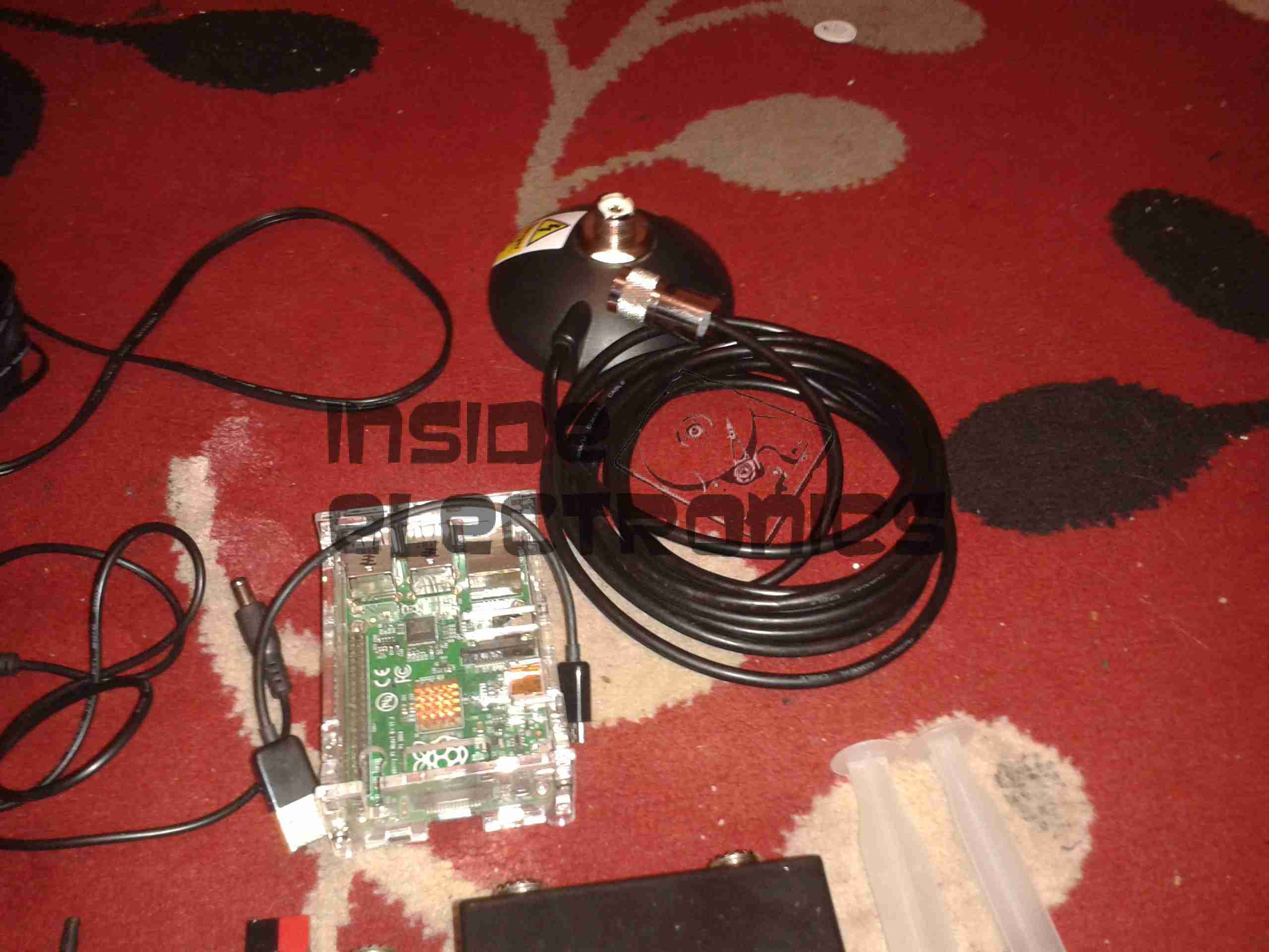
Magmount & Pi
Main antenna magmount & a spare Raspberry Pi.
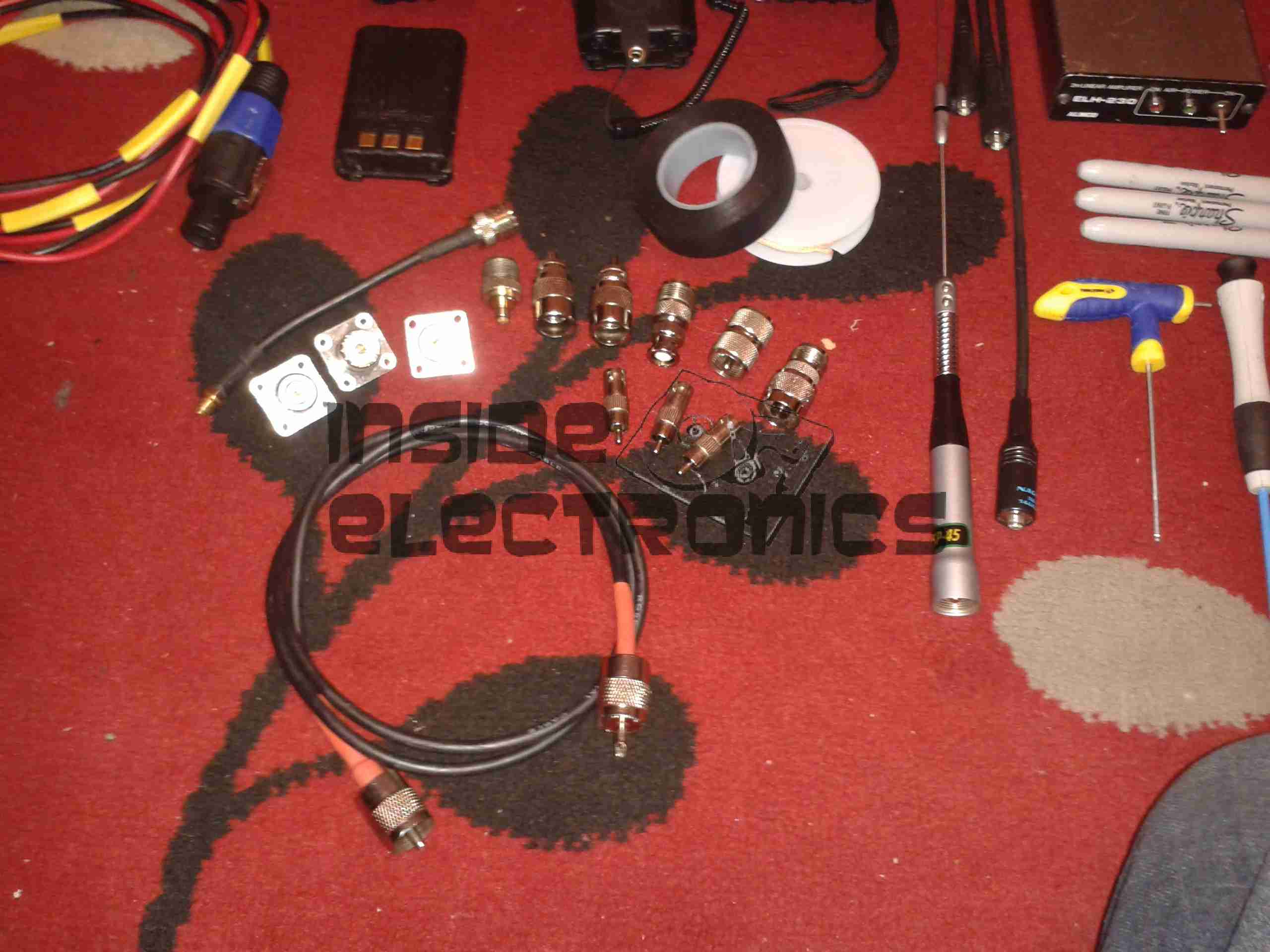
Antenna, Patch Leads, Etc.
Finally, the antennas for the HTs, main dual-band antenna (Nagoya SP-45) for the magmount, a small selection of spare plugs, sockets & adaptors. Also here is a roll of self-amalgamating tape, very handy for waterproofing wiring connections (especially when used in conjunction with the silicone grease), & a roll of solder wick.
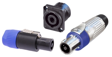
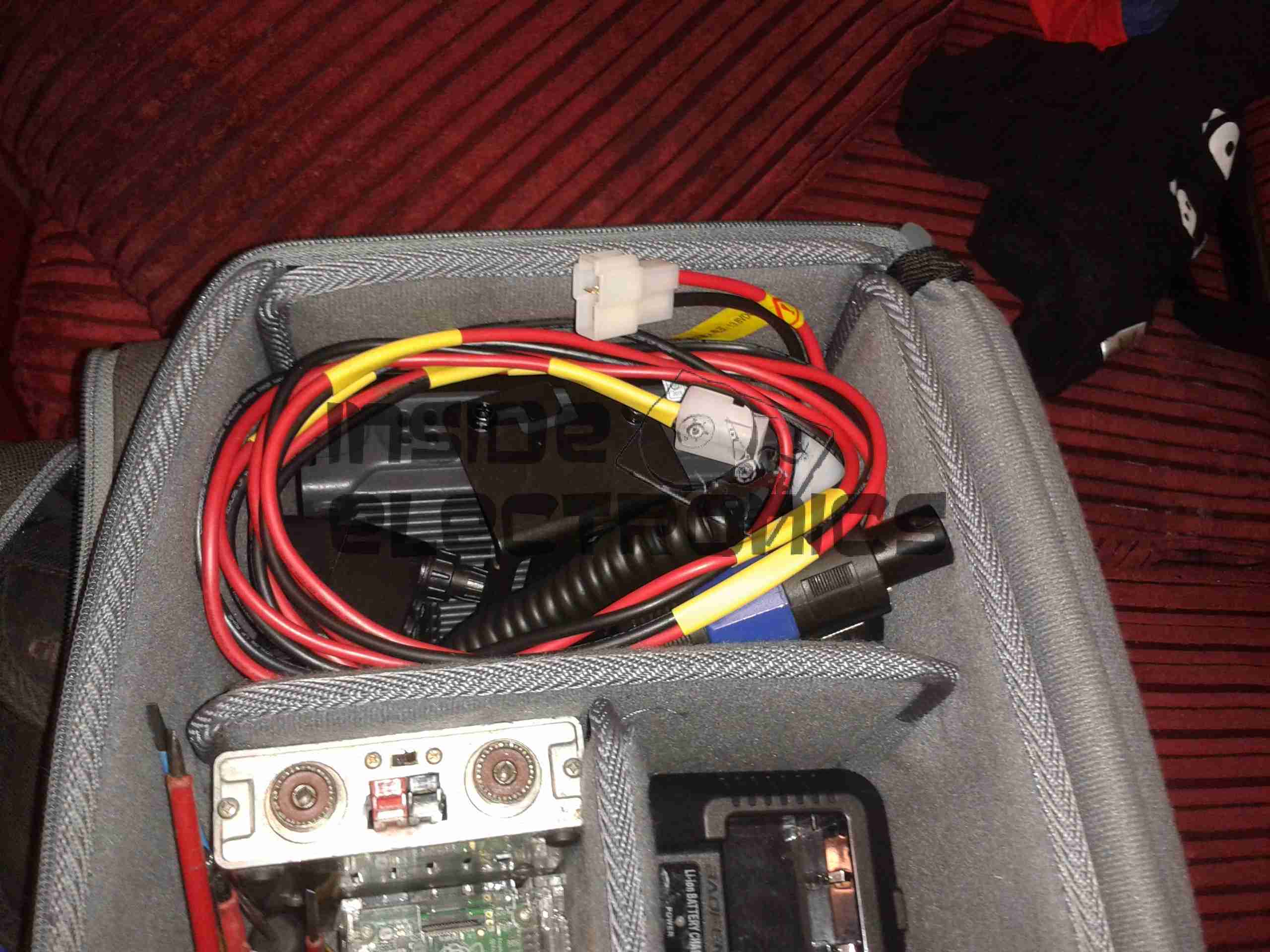
Now, the main power connectors of choice for my equipment are Neutrik SpeakOn type connectors:
Neutrik SpeakOn
These connectors have many advantages:
They are positive locking connectors. No more loose connections.
They have a high continuous current rating of 30A RMS.
Relatively weather resistant.
Also, they have two pairs of pins – and as some of my bigger non-radio related equipment is 24v, this allows me to use a single set of plugs for everything. Without having to worry about plugging a 12v device into a 24v socket, and letting out the magic blue genie.
Once everything is packed up, here’s the bag:
Packed
Everything has a neat little pocket for easy access. Some closeups below.
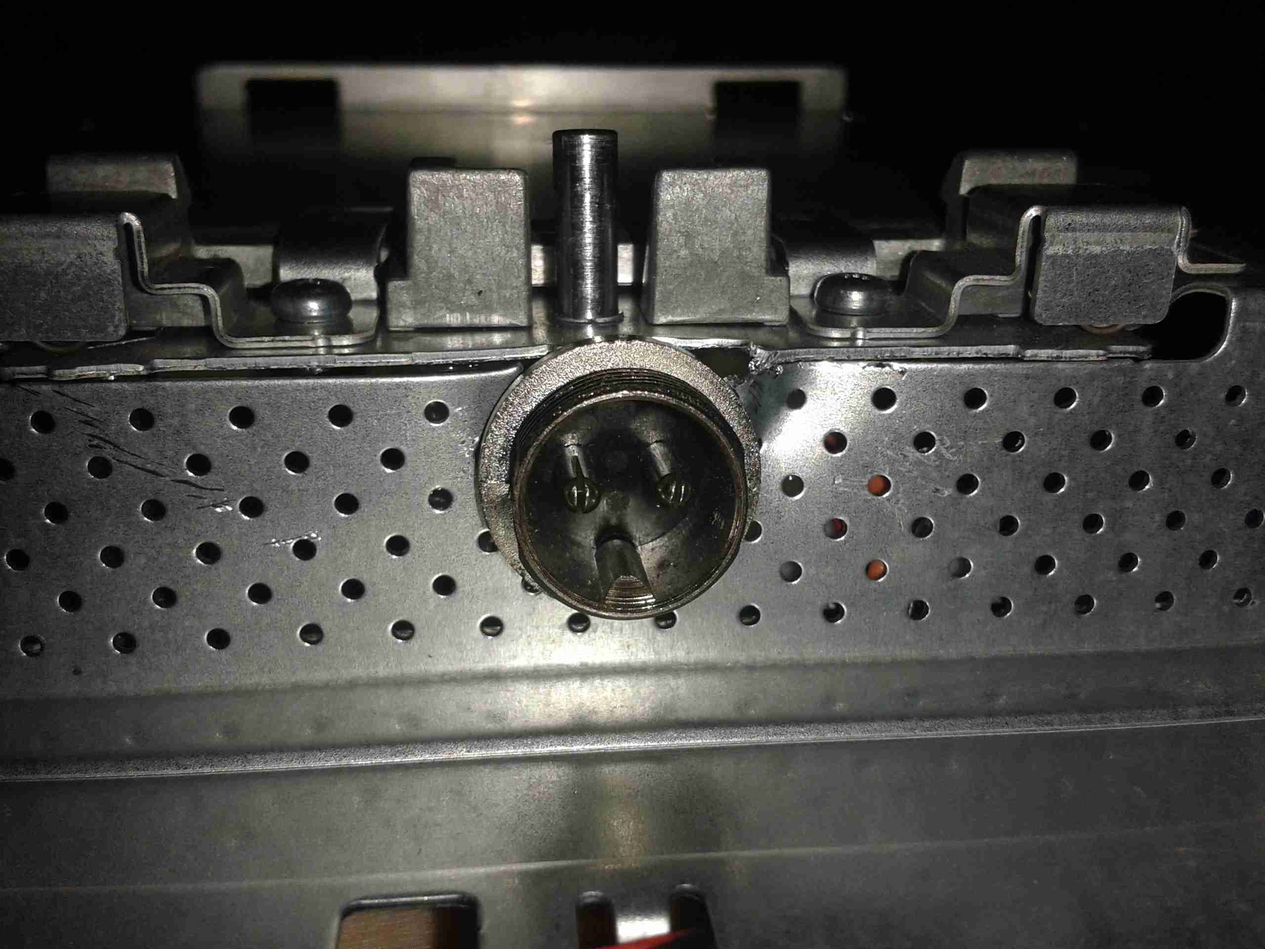
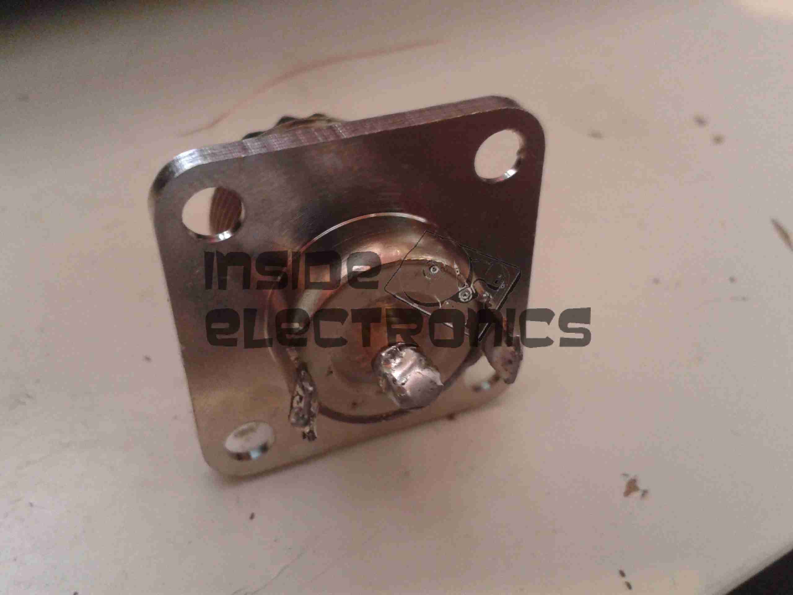
In my original review, I noted that this radio was supplied with a SO-259 socket for the antenna connection.
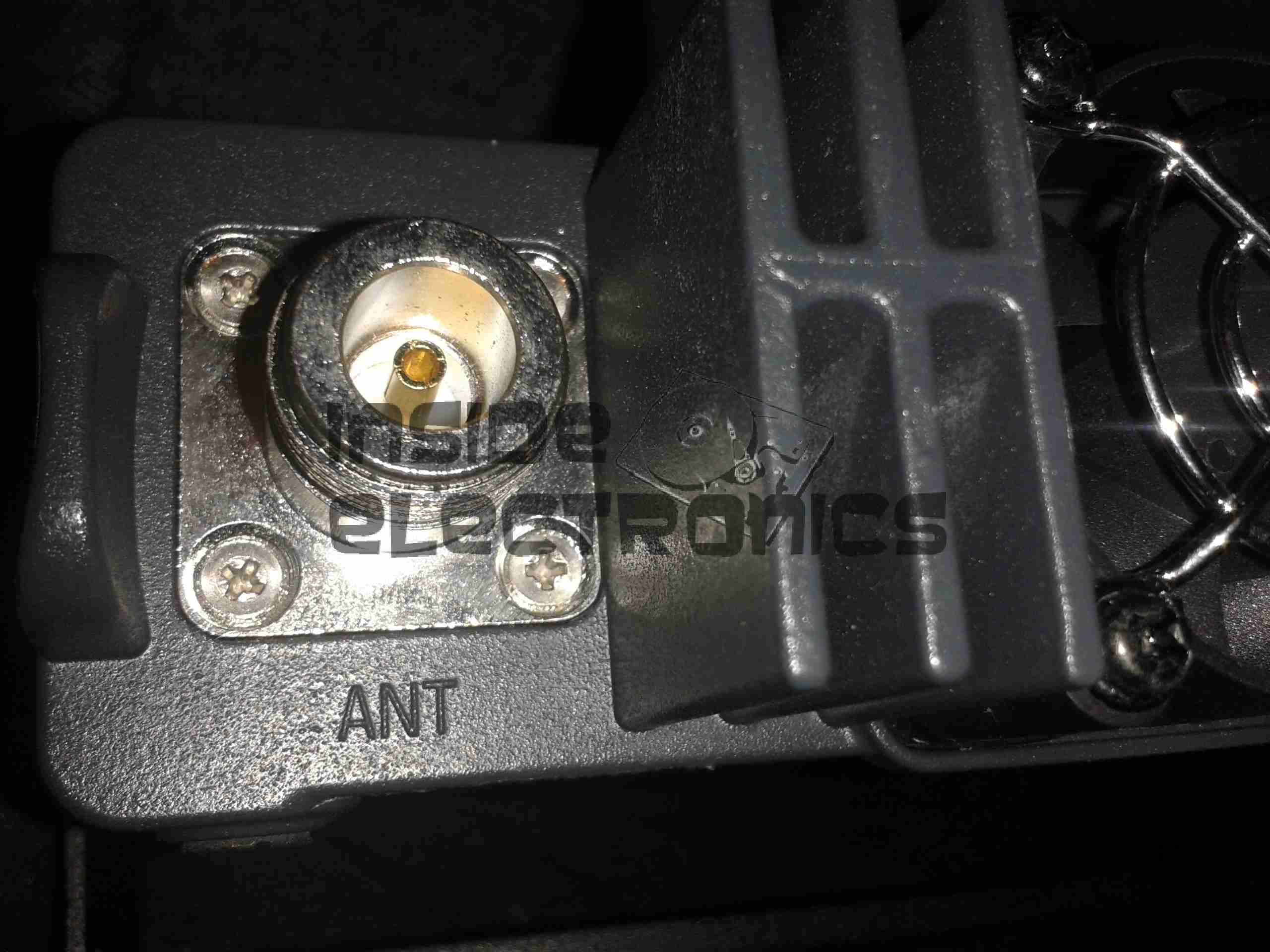
However I’m less than fond of these, due to their non-constant impedance, which can cause signal loss issues at VHF/UHF. Because of this, I’ve replaced it with a high quality N-type connector. These connectors are much better, as they are a constant 50Ω impedance, they’re weather resistant, and being rated to 11GHz, are more than sufficient for a radio that will only do up to 70cm.
RF Output Jack
Here can be seen the point where the connection is made to the PCB.
I’ve already replaced the socket in this photo. The pair of solder pads either side of the central RF point were soldered to wings on the back of the original SO-259. As there are a pair of screws, also connected to the ground plane, there have been no signal issues with just using the frame of the radio as the ground point. Shown below is the original socket, with the ground wings.
Original SO-259
Finally, here is the back of the radio with it’s shiny new N connector.
New Connection
Chassis mount connectors are pretty standard, so this new connector fits perfectly into the same recess of the original. Looks like factory fitted!
I am now standardising on N connectors for everything in my radio shack, next on the project list for conversion is the SWR meter I recently acquired.
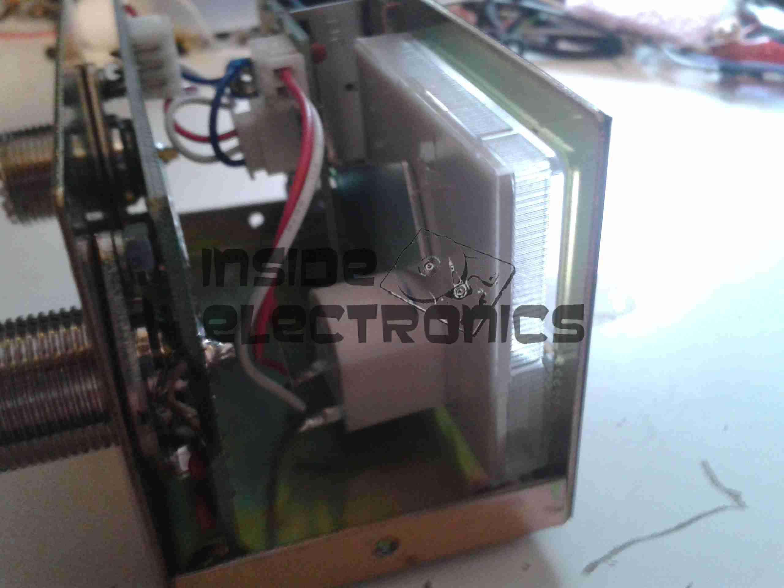
Following on from my review, here are some internal views & detail on the components used in this radio. Below is an overview of the main PCB with the top plate removed from the radio.
Cover RemovedRF Final Amplifier Stage
Most visible are these MOSFETs, which are Mitsubishi RD70HVF1 VHF/UHF power devices. Rated for a maximum of 75W output power at 12.5v (absolute maximum of 150W, these are used well within their power ratings. They are joined to the PCB with heavy soldering, with bypass caps tacked right on to the leads.
RF Pre Drivers
Here is the RF pre-driver stage, with intermediate transistors hidden under the small brass heatspreader.
Power Section
In the top left corner of the radio, near the power input leads, is the power supply & audio amplifier section. Clearly visible are the pair of LA4425A 5W audio power amplifier ICs, these drive the speakers on the top of the radio. Either side of these parts are a 7809 & a 7805 – both linear regulators providing +9v & +5v logic supplies respectively. The large TO220 package device is a KIA378R08PI 3A LDO regulator with ON/OFF control, this one outputs +8v. Just visible in the top right corner are the sockets for the speaker connections.
DTMF Circuits
Here are the two ICs for dealing with DTMF tones, they are HM9170 receivers.
Glue Logic
In the corner next to the interface jack, there are some CD4066B Quad Bilateral switches. These make sense since the interface jack has more than a single purpose, these will switch signals depending on what is connected.
RF Section
Here are visible the RF cans for the oscillators, the crystals visible next to the can at the top. The shields are soldered on, so no opening these unfortunately.
Also visible in this image is a CMX138A Audio Scrambler & Sub-Audio Signalling processor. This IC deals with the Voice Inversion Scrambling feature of the radio, & processes the incoming audio before being sent to the modulator.
Output Filter Network
Shown here is the RF output filter network, this radio uses relays for switching instead of PIN diodes, I imagine for cost reasons. The relay closest to the RF output socket has had a slight accident 🙂 This is slated to be replaced soon.
RF Output Jack
Finally, the RF output jack.
Audio Speakers
Here the speakers are shown, attached to the bottom of the top plate. They are both rated 8Ω 1W.
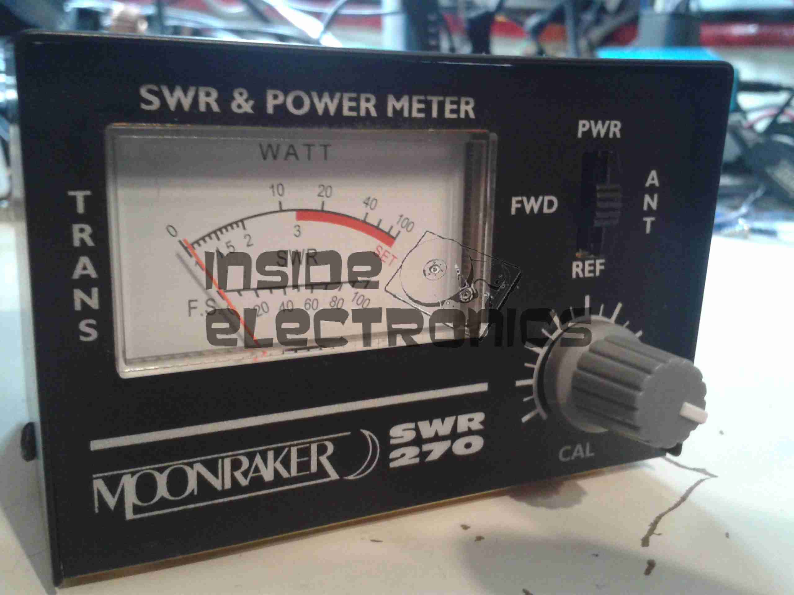
As I’m building up my radio shack, I figured an SWR meter would be a handy addition to my arsenal. This is a cheap Moonraker brand meter, which also will measure RF power. Above the front of the meter is shown, with the moving coil meter movement on the left, calibration adjustment on the right & the forward/reverse power switch.
Meter Rear
For connections, standard SO-259 jacks are provided. The casing is sturdy 1mm steel. This is good, considering it’ll probably take a beating in my portable radio bag.
Directional Coupler PCB
Here the cover is removed, showing some of the internals. The large PCB across the back is the directional coupler.
Directional Coupler Circuit
The SO-259 connectors are bridged with a transmission line, (the track covered in solder in the image below), while there are a pair of sense lines running alongside. This main line is electromagnetically coupled to the two smaller sense lines, which are terminated at one end with resistors, with diodes at the other to rectify the coupled signal.
The termination resistors are sized to match the impedance of the sense lines.
The diodes, having rectified the coupled RF, produce DC voltages representing the value of the forward & reverse RF power. These DC voltages are smoothed with the capacitors.
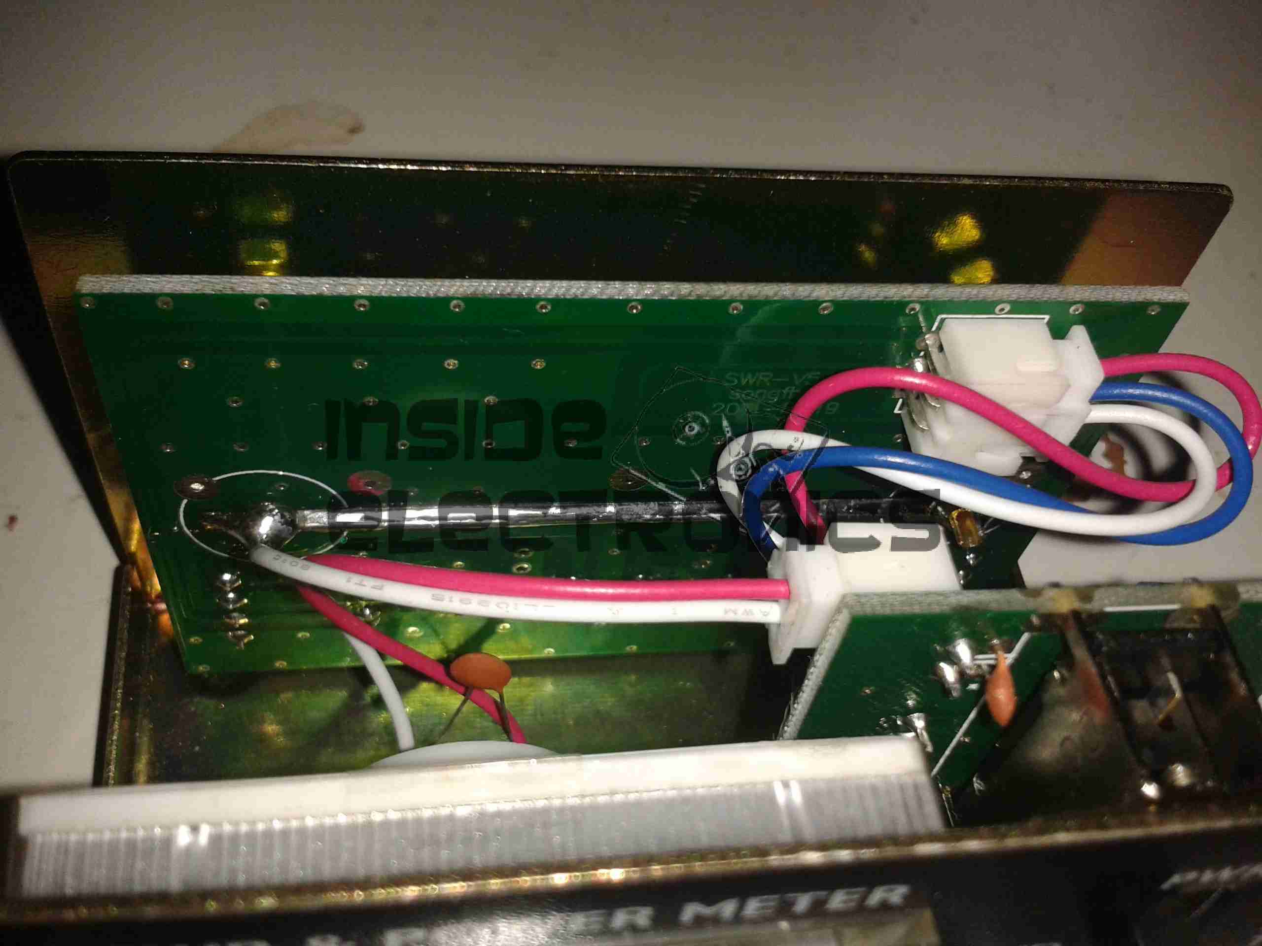
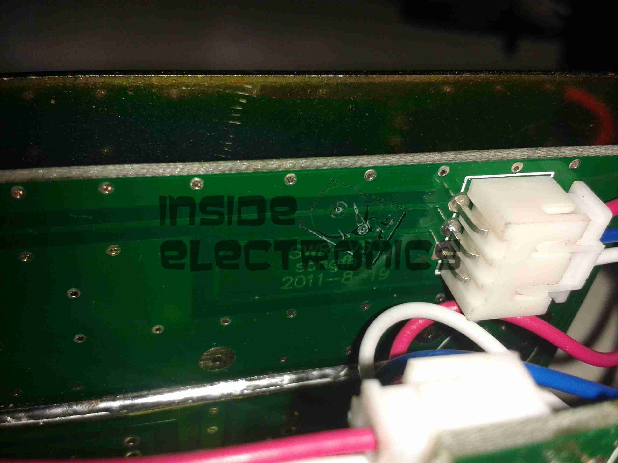
PCB Marking
The PCB is dated 19-8-2011, so it’s a fairly old design.
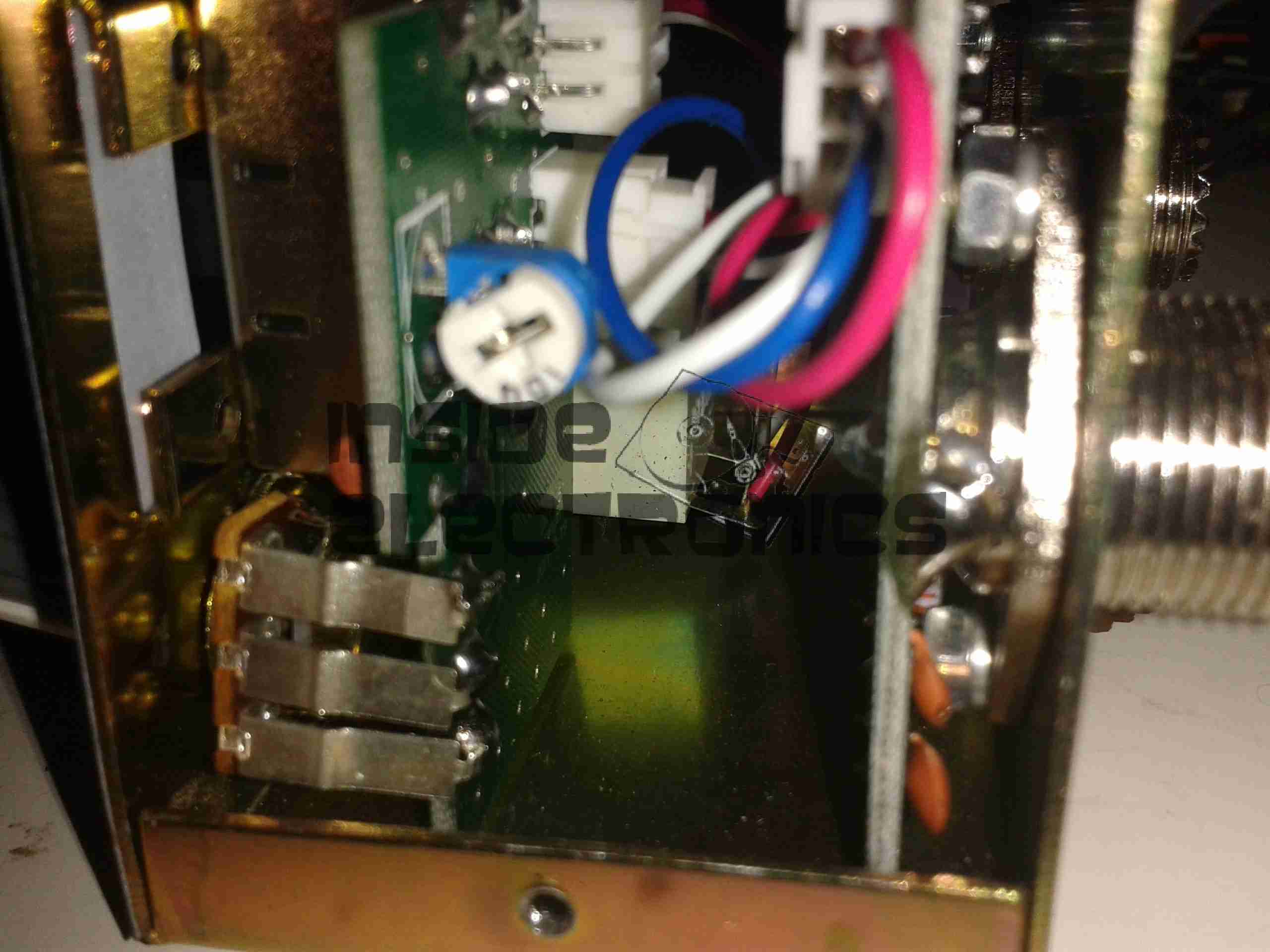
Adjustments
Here is visible the back of the user calibration adjuster, with the factory calibration trimmer.
Meter Movement
Back of the meter movement. This is a standard moving coil type. Nothing special.
This meter will soon be modified to accept connection of an external Arduino-based SWR & power meter, which I can calibrate individually for each band.
Stay tuned for that upcoming project.
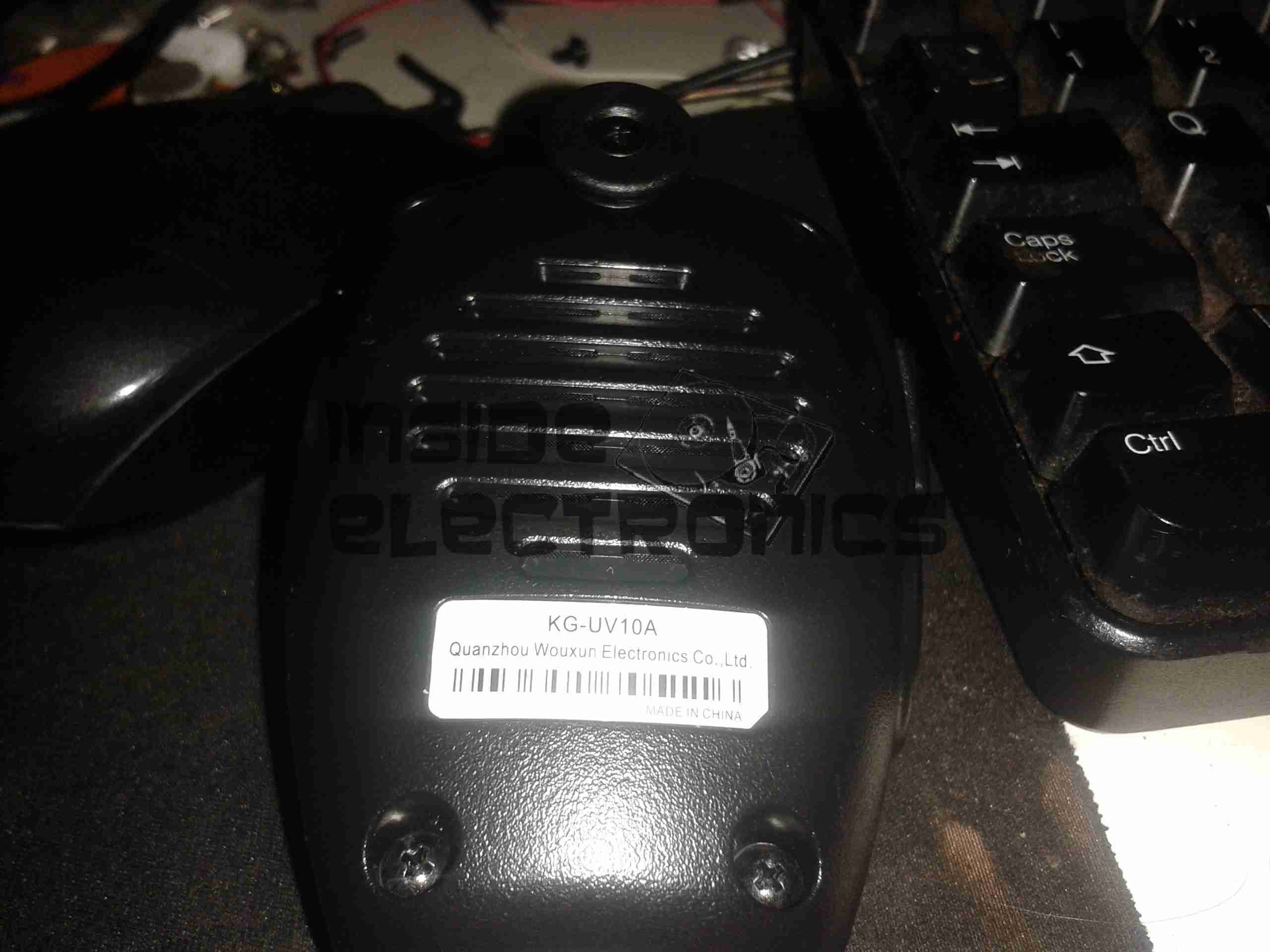
After running on handies for all of my Ameteur Radio life, I figured it was time for a new radio, this time a base station/mobile rig, & after some looking around I decided on the Wouxun KG-UV950P.
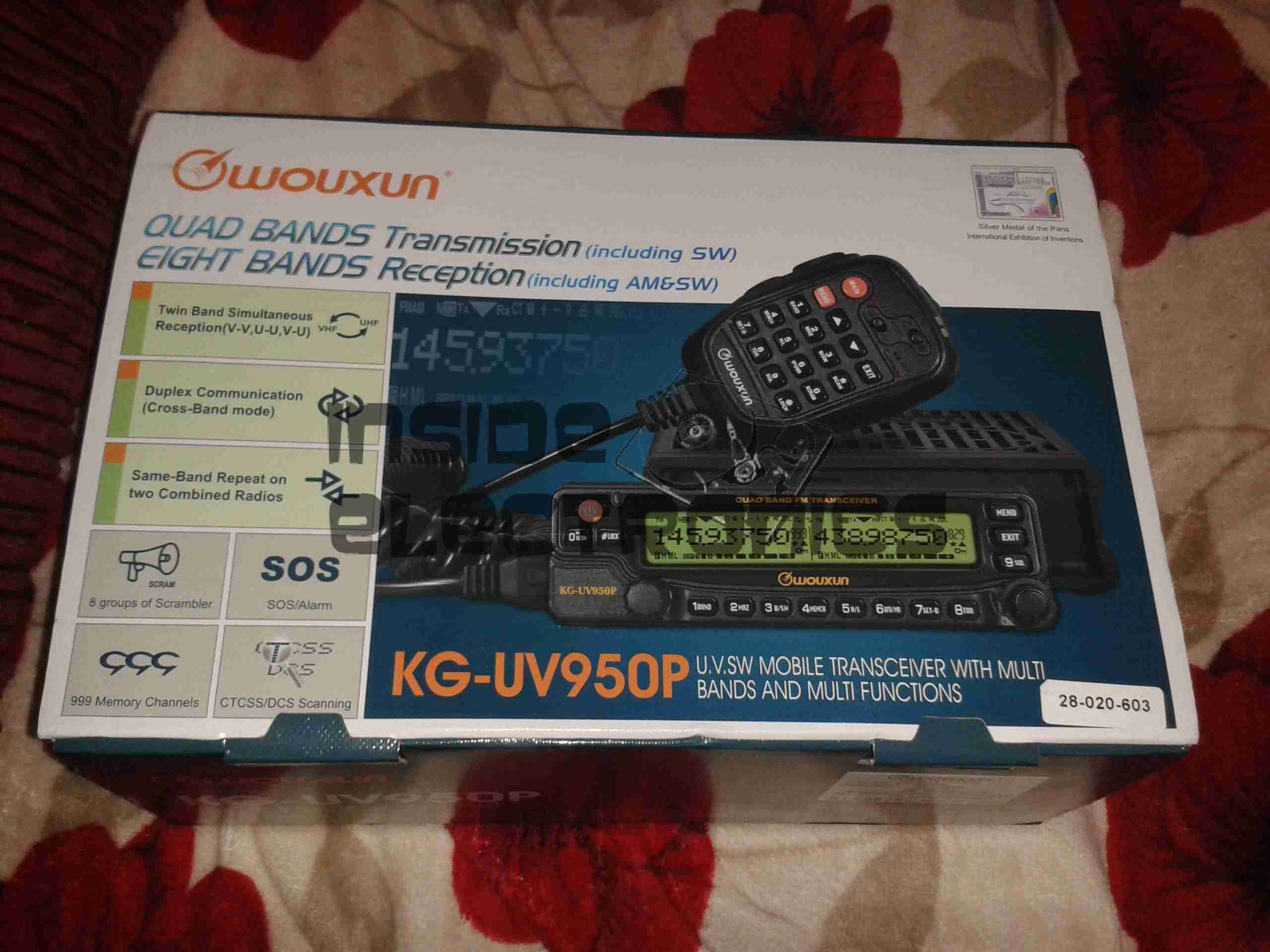
Shown below is the radio as delivered:
Wouxun Boxed
This radio has the capability to transmit quad-band, on 6m, 10m, 2m & 70cm. It also has the capability to receive on no fewer than eight bands. Also included in the feature set is airband receive, & broadcast FM receive.
TX power is up to 50W on 2m, 40W on 70cm, & 10W on 6m/10m.
Opened
For once with a Chinese piece of electronic equipment, the manual is very well printed, and in very good English.
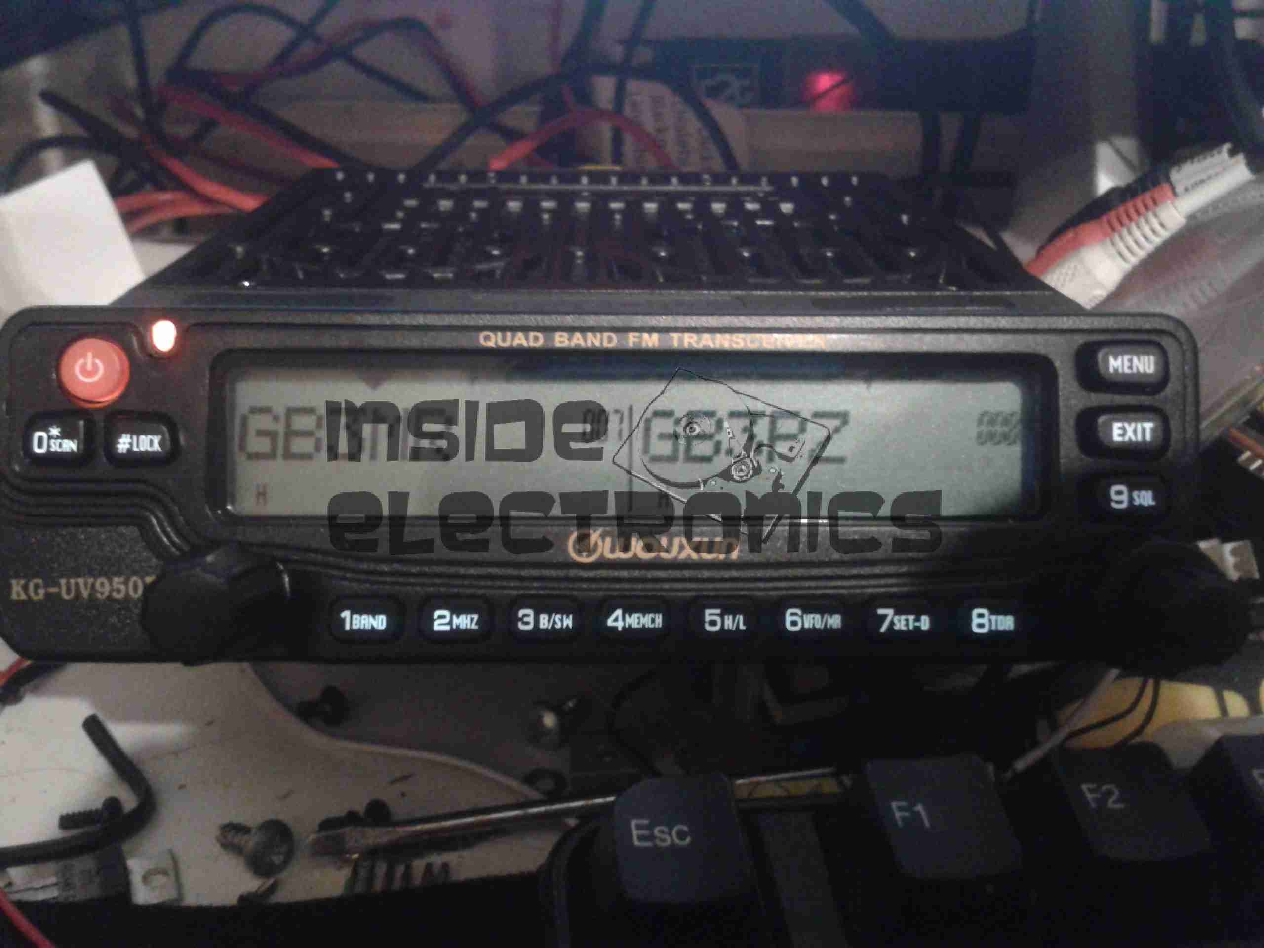
Radio Operating
Here is the radio in operation, connected to my 65A 12v power supply. I have the radio set here monitoring a couple of the local 70cm repeaters.
The display is nice & large – easy to see at a glance which station you’re tuned to. The backlight is also software settable to different colours.
Status indicators on the top edge of the display can be a bit difficult to see unless the panel is directly facing the user though, not to mention that they are rather small.
This radio is true dual-watch, in that both VFOs can be receiving at the same time, this is effected by a pair of speakers on the top panel:
Speakers
The left VFO speaker is smaller than the right, so the sound levels differ slightly, but overall sound quality is excellent. There is also provision on the back of the unit to connect external speakers.
The dual volume controls on the right hand bottom corner of the control panel are fairly decent, if a little twitchy at times. There is also a fair amount of distortion on the audio at the higher volume levels.
The controls themselves are potentiometers, but the controller appears to read the setpoint with an ADC – this means that if the control is set to just the right point, the selected level will jump around on the display & never settle down.
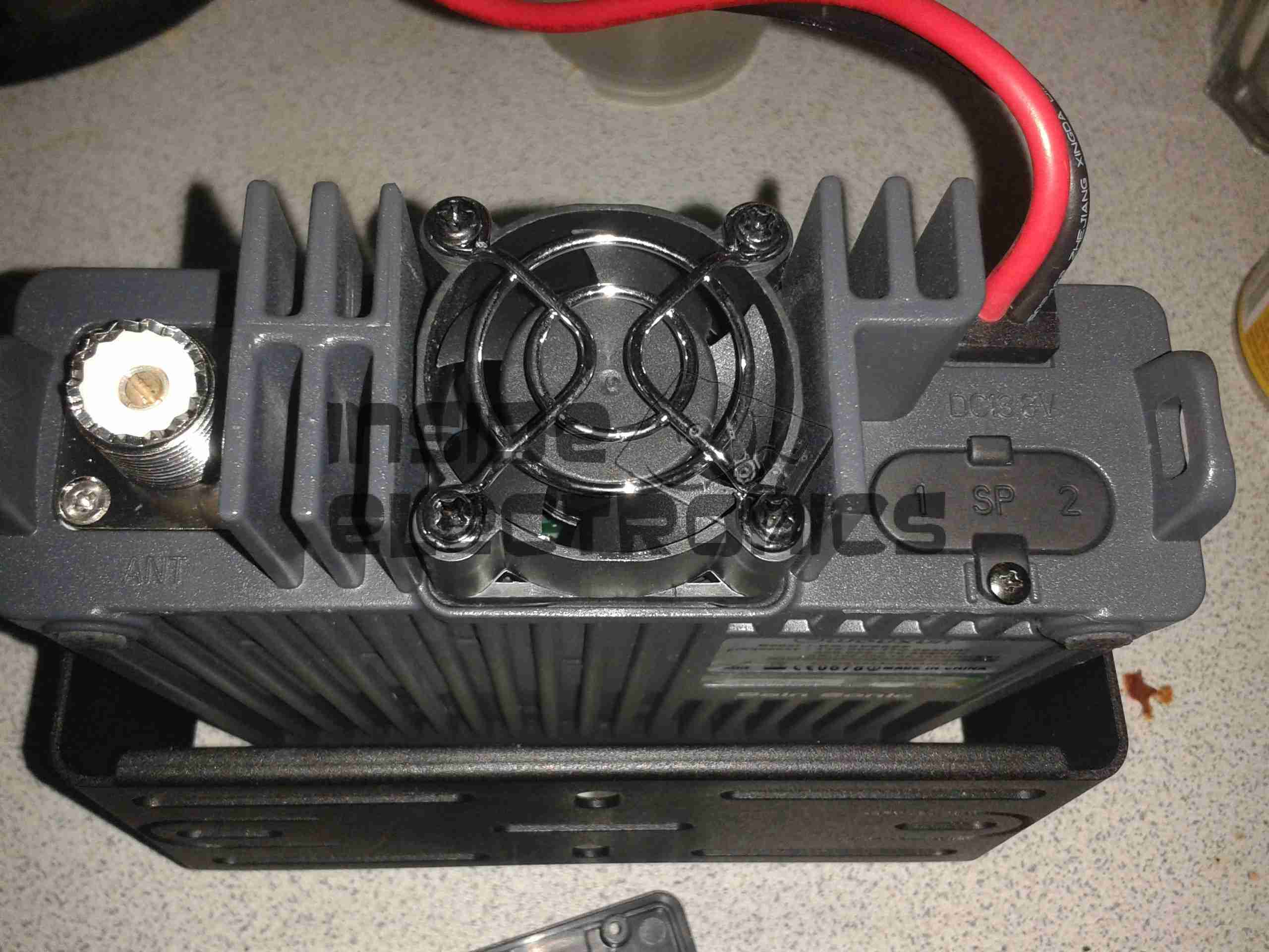
The radio itself is built from a solid aluminium casting, mostly for heatsinking of the main RF output stage MOSFETs. This gives the radio a very rugged construction.
A small fan is provided on the rear for cooling when required. This can be set in software to either be constantly running, (it’s pretty much silent, so this is advantageous), or only run when in TX mode. The fan will also automatically come on when a high internal temperature is detected.
Hand Mic
Here is the microphone. Like the main unit of the radio this is also very solidly built, fits nicely in the hand & the PTT has a nice easy action, which helps to prevent straining hands while keeping the TX keyed.
Conveniently, all of the controls required to operate the radio are duplicated on this mic, along with a control lock switch, & backlighting for the buttons.
Another Speaker
Another output speaker is placed in the back of the mic. This one can be activated through the menu system, to either use the main body speakers, the mic mounted one, or both.
A mounting hook for the mic is provided to attach to any convenient surface.
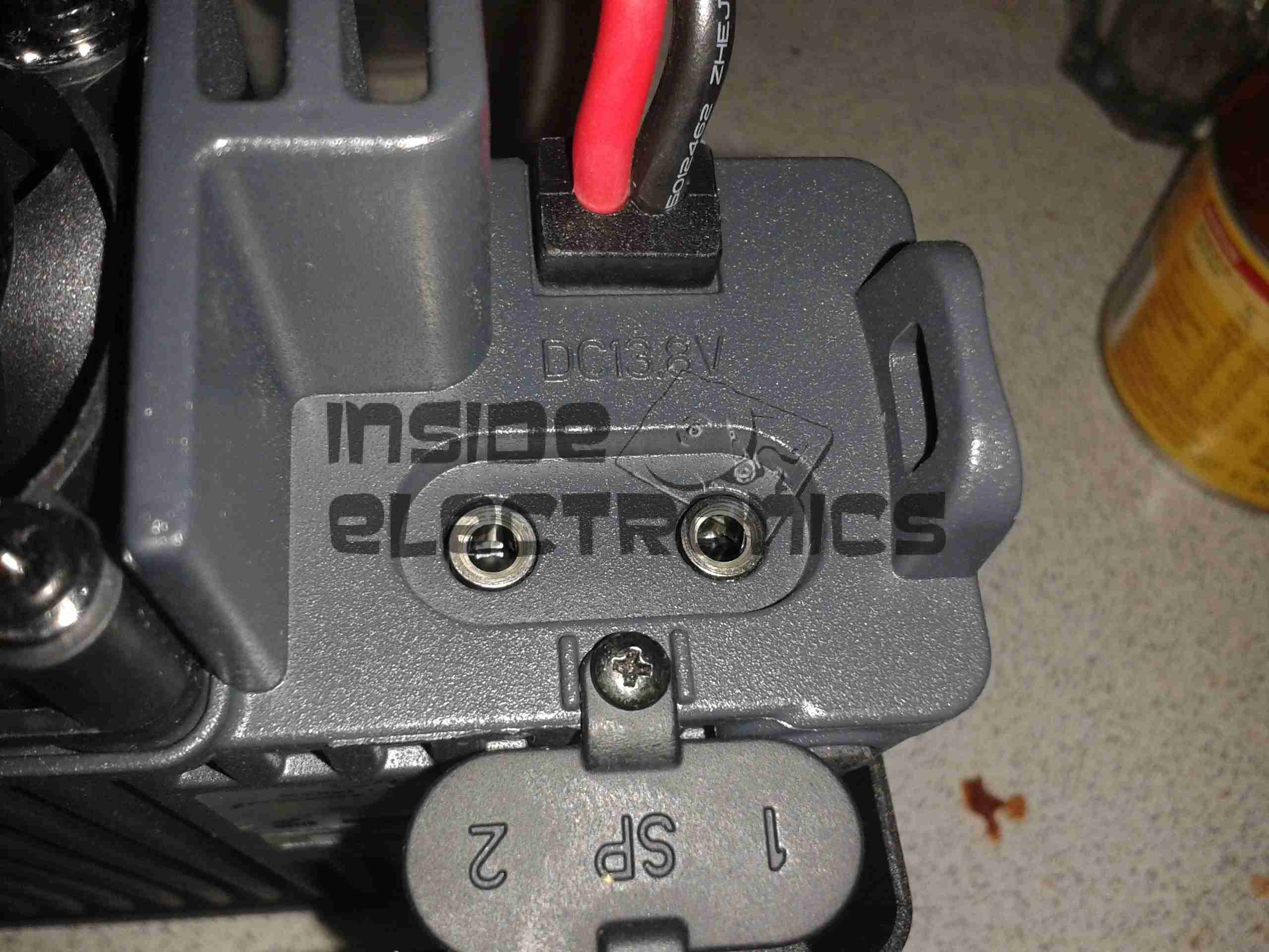
Radio Back
Here’s the back of the radio, with some of the big heatsink fins, the fan in the centre. To the left is the PL259 RF output, this looks to be a high quality Teflon insulated one. On the right are the power input leads & the external speaker outputs.
External Speaker Sockets
The external speaker connections are via 3.5mm jacks. I haven’t yet tested this feature.
Remote Mounting Plate
The control panel of this radio is detachable from the main body, and a pair of adaptors are provided. This either allows the radio display to be angled upwards toward the user, set parallel, or even mounted remotely. A control extension cable is provided to allow the main body to be mounted a fair distance away.
External Interface Connectors
On the left of the radio is the PC control & programming port, & the mic connector. Wouxun *really* like RJ-45 connectors, they’ve used them for everything on this radio.
Also visible here is the tilted faceplate adaptor.
The supplied software to program the radio, while functional, is absolutely horrific. Hopefully someone will add support for this radio into CHIRP. Anything would be an improvement in this area.
Everything considered, I like this radio. It’s very solidly built, easy to use, and sounds brilliant.
TX audio is great, (or so my other contacts tell me).
Unsurprisingly, the unit gets warm while transmitting, however on high power, it does get uncomfortably warm, and the built in fan does little in the way of helping when a long QSO is in progress. I may remedy this at some stage with a more powerful fan. A little more airflow would do wonders.
If the programming software was built as well as the radio, I’d have zero serious complaints.
At full power, the radio pulls ~10A from the power supply, at 12.9v DC.
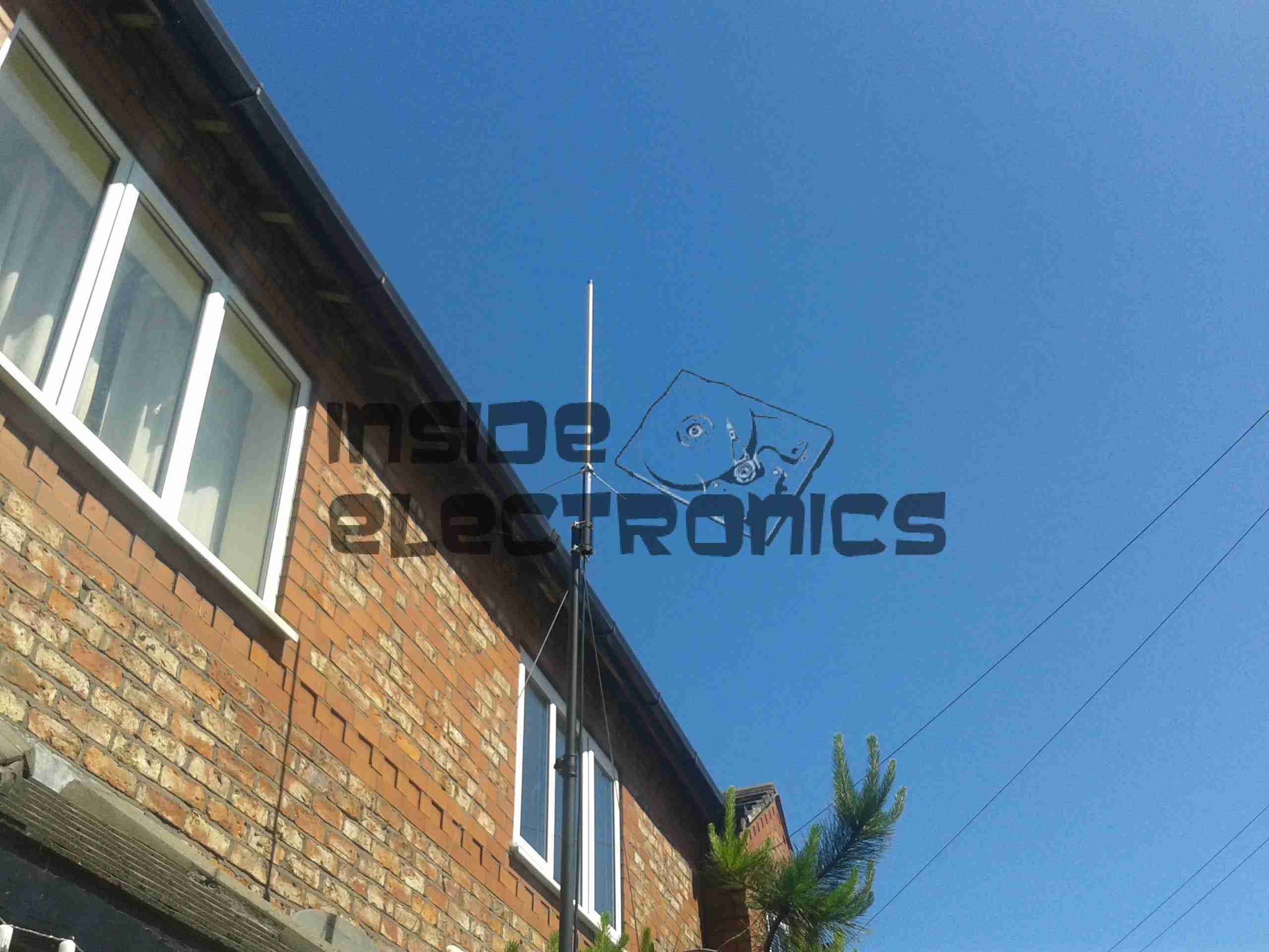
As for the antenna I’m currently using, it’s a Diamond X30, mounted on a modified PA speaker stand, at ~30 feet above ground. The feeder is high quality RG-213.
TX Antenna
When I manage to get the set disconnected, a partial teardown will be posted, with some intimate details about the internals. Stay tuned!
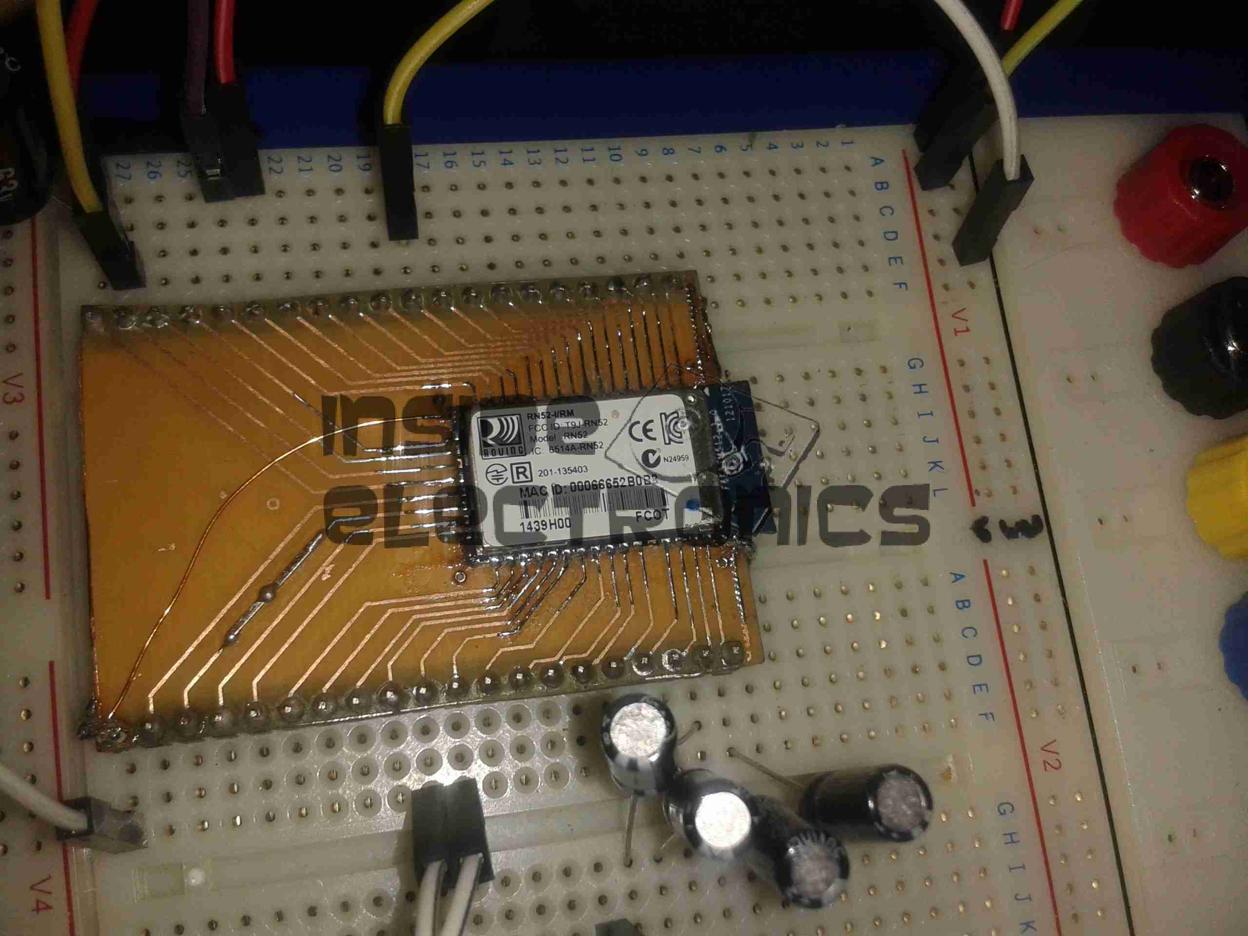
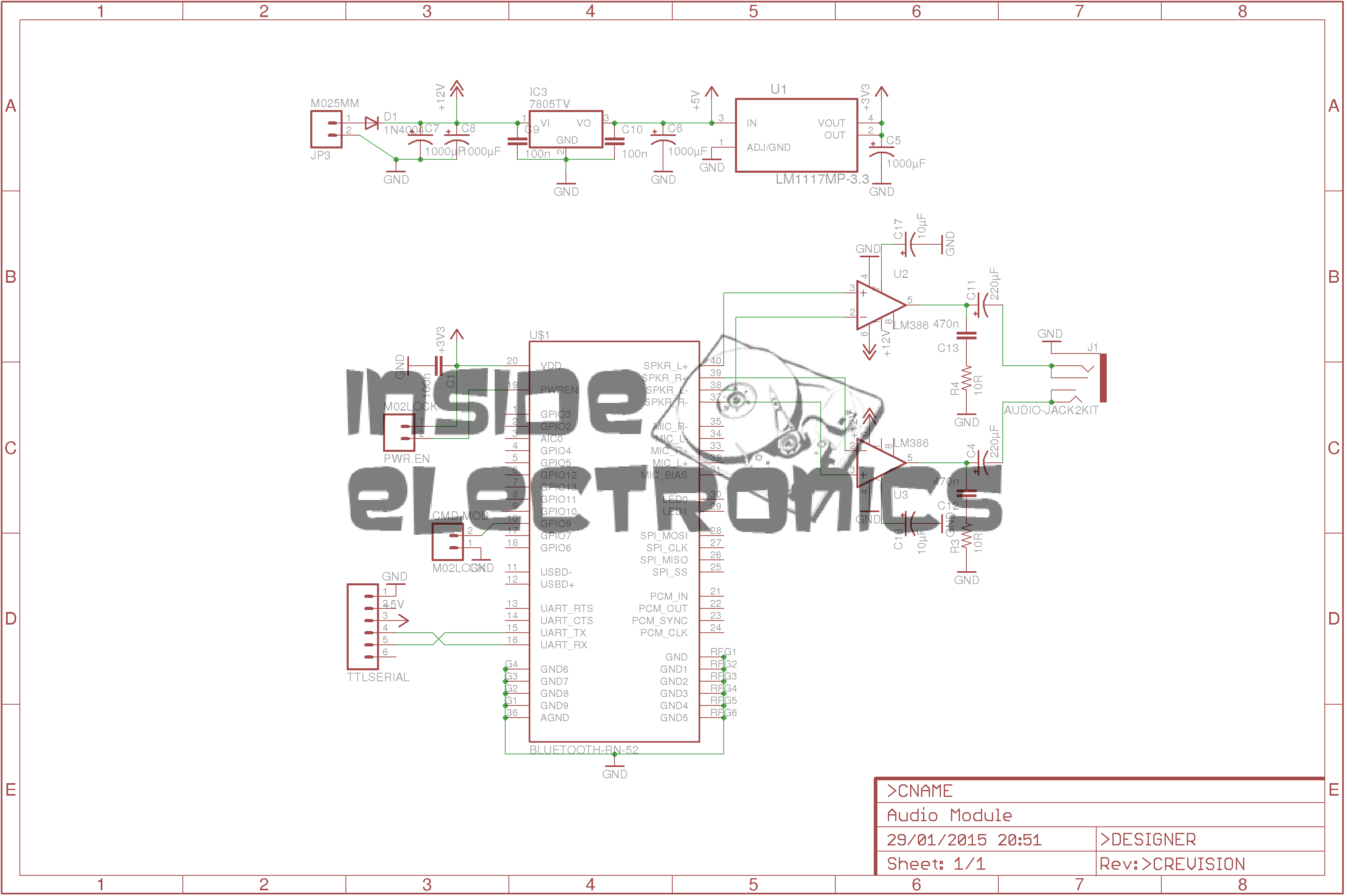
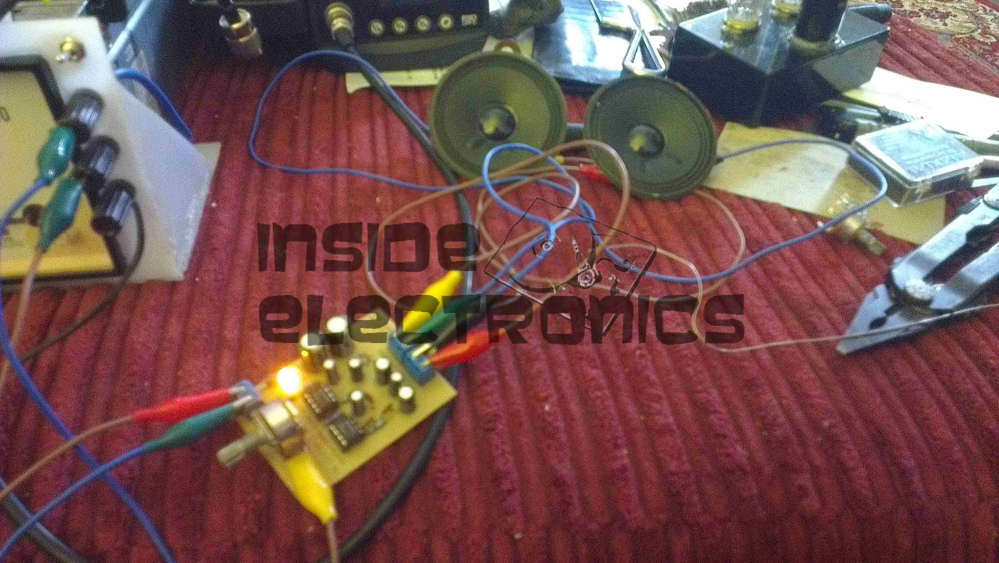
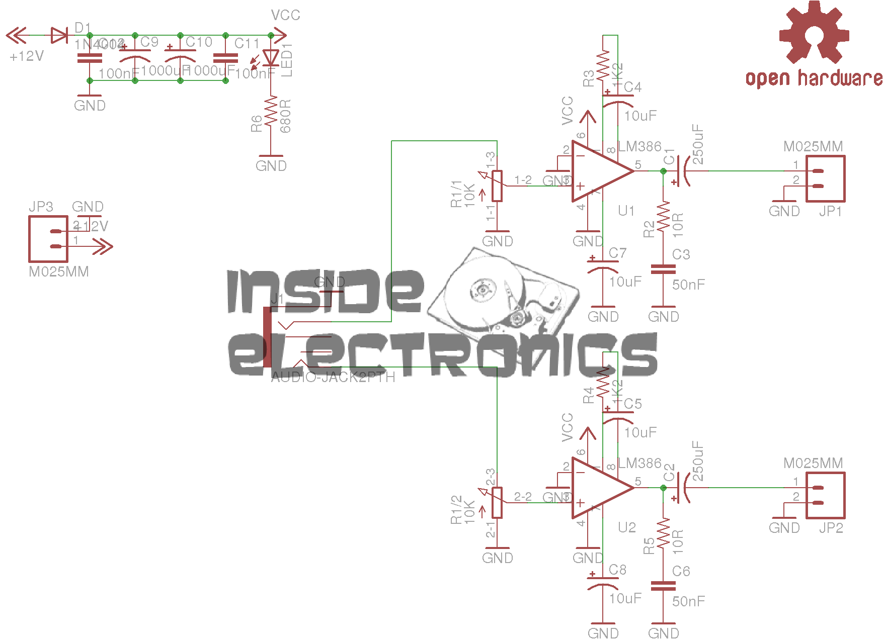
I’ve been doing some tinkering with the RN-52 Bluetooth Audio module from Roving Networks, in prep for building a portable wireless speaker system, & thought I’d share my designs.
Initially I was having some issues with RF noise on the audio output from the RN-52, as I was only using the outputs single-ended. The module didn’t like this treatment, with all the RF whine coming straight out of the speakers.
To fix this issue I have used a pair of jellybean LM386 audio power amplifiers, running in differential input mode. This solves the high-pitched whine when the audio is enabled, & also allows the module to directly drive a set of 32Ω headphones at a reasonable level.
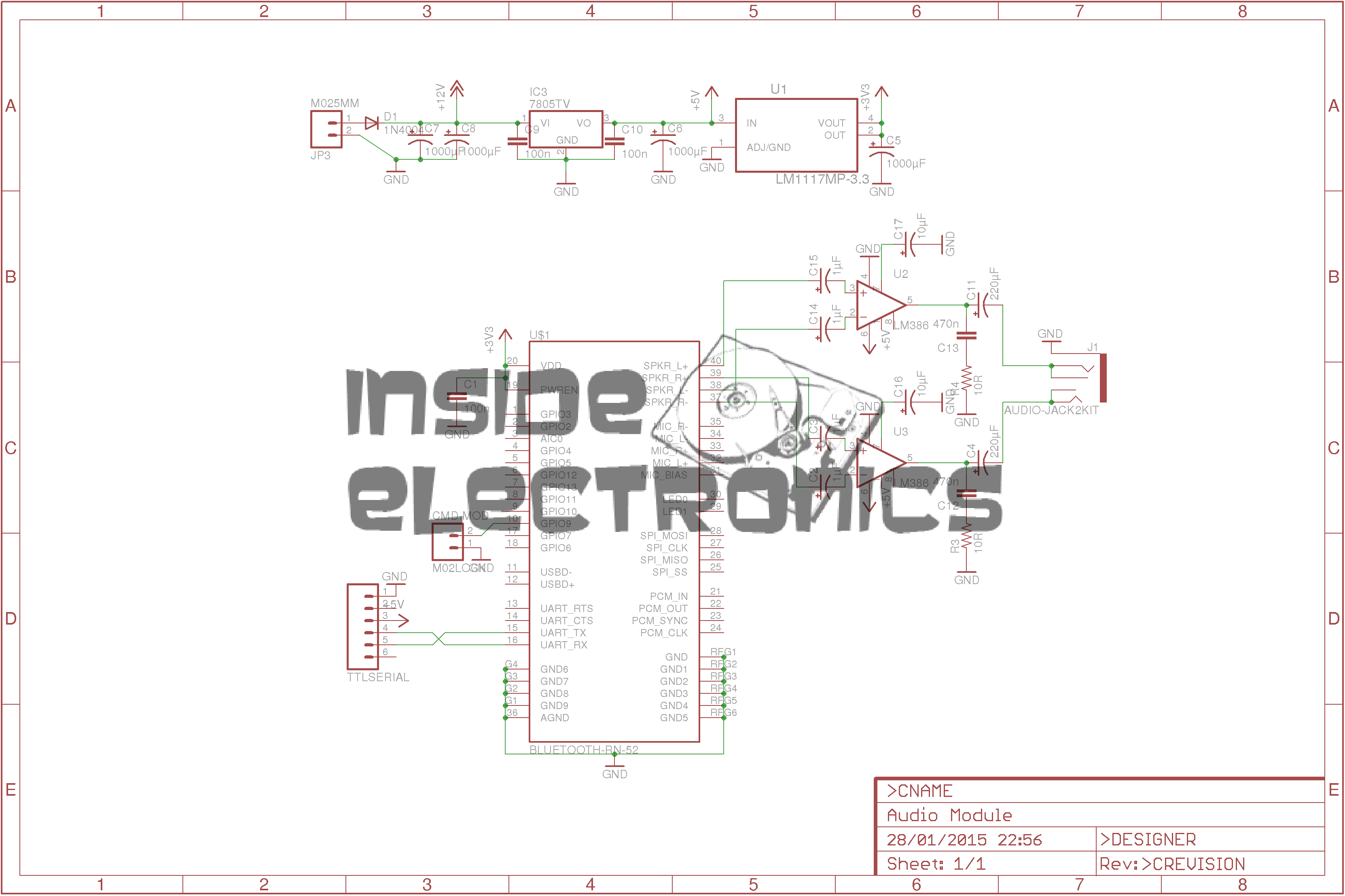
In Eagle I have designed a simple board, routing only the audio output, serial TTL & command mode pins out, along with the supporting power supply circuitry to operate from 12v DC.
RN-52 Breadboard
Above is the current incarnation of the circuit on the breadboard. The RN-52 is on the left, audio power stage in the centre & headphone output on the right.
RN-52 Breakout
The bluetooth module on a breakout board. I was cheap in this case & etched my own board. I’m not paying Sparkfun, (as much as I like them), an extra ~£10 for a small PCB with the pins broken out. Much cheaper to spend 15 minutes with the laser printer & the iron, & do a toner transfer PCB.
As this board is single sided, I added a ground plane on the underside with copper foil, to help with the RF issues. Breadboards really aren’t all that good at rejecting noise induced when there’s a 2.4GHz transceiver mounted on them.
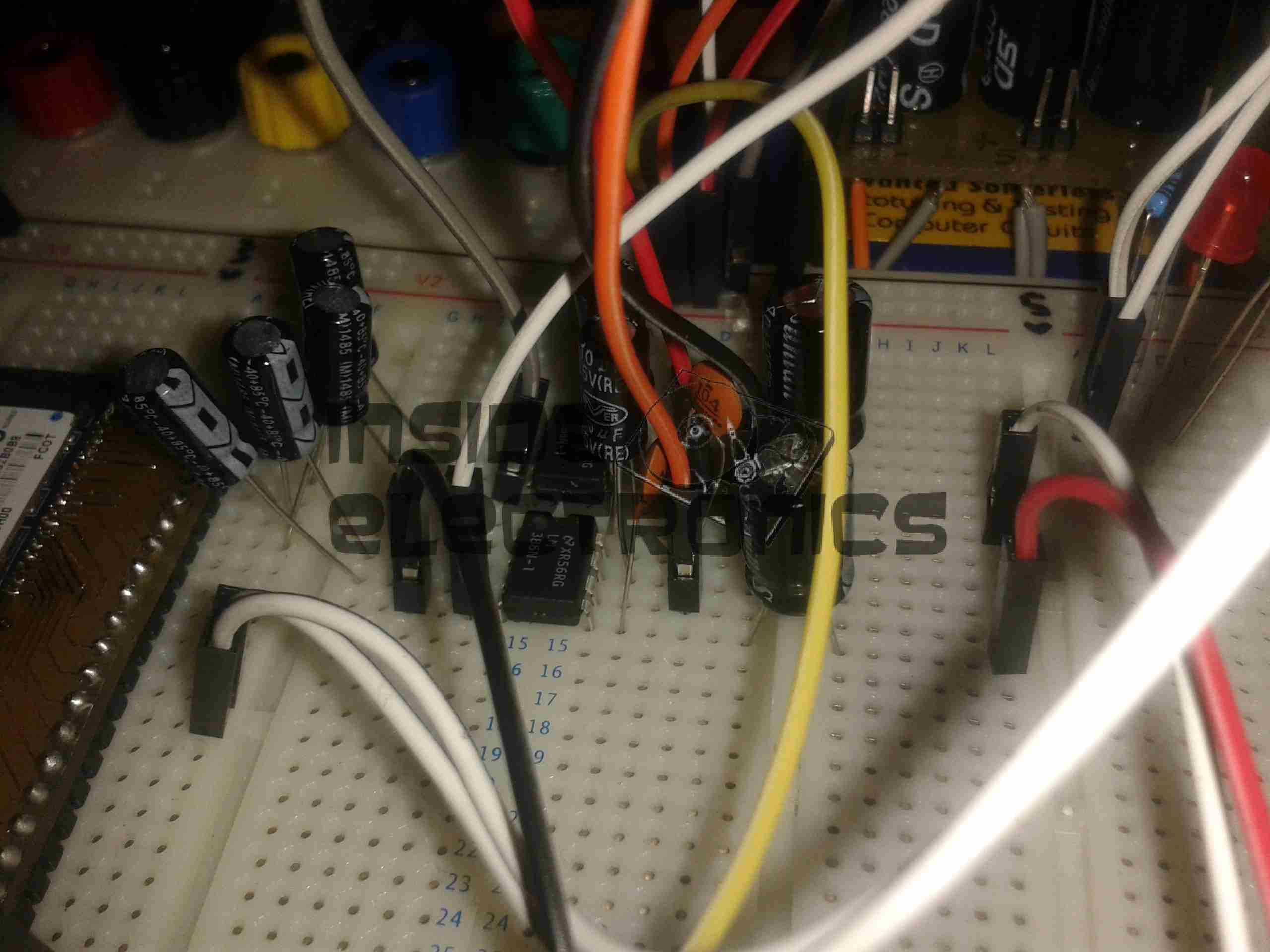
LM386 Amplifier
The LM386 audio power stage. The differential inputs from the module are capacitively coupled with 1µF electrolytics. This setup remarkably reduced the noise on the output. I left these at their default gain of 20, as I’ll be connecting another high power amplifier stage to drive large speakers.
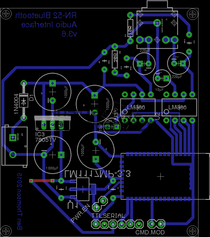
RN-52 Eagle Layout
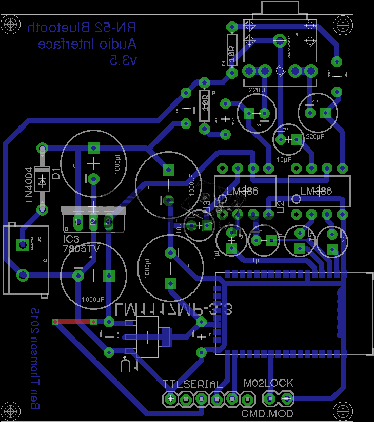
Here’s the circuit laid out in Eagle, ready for PCB.
RN-52 Eagle PCB
And here’s the PCB layout. Only one link required for the +5v line from the TTL serial port.
As always, the Eagle PCB & Schematic layout files are available at the bottom of the article.
*Update 29-01-15*
Rerouted a few things:
Moved the audio power stage to the +12v rail to improve sound response. – As the LM386 has a max input voltage of 12v (absolute maximum 15v), a regulated supply is recommended. The LM386-N4 variant has a higher voltage range, up to 18v. This should be suitable for an unregulated supply.
Removed 1µF coupling capacitors to reduce distortion & amplifier hiss. The capacitors appeared to cause some instability on the amplifier, causing random distortion. Removing them has cured this. No signal hiss has also been reduced to a very low level.
Reversed input polarity on input of one of the amplifiers – this appears to produce better audio.
Added PWR.EN header to allow connection of power button. Saves hassle of cycling power to the board when the RN-52 goes into sleep mode.
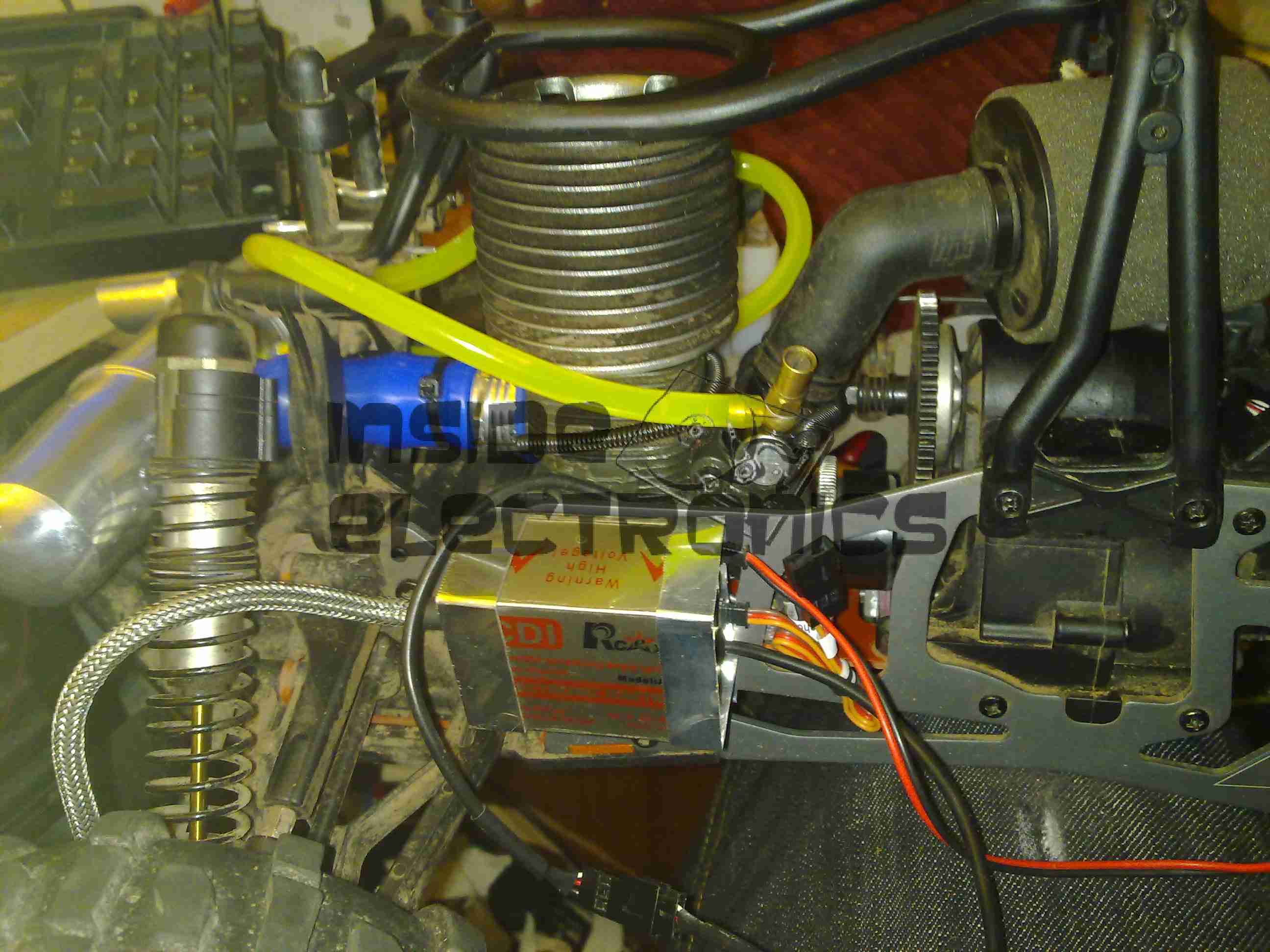
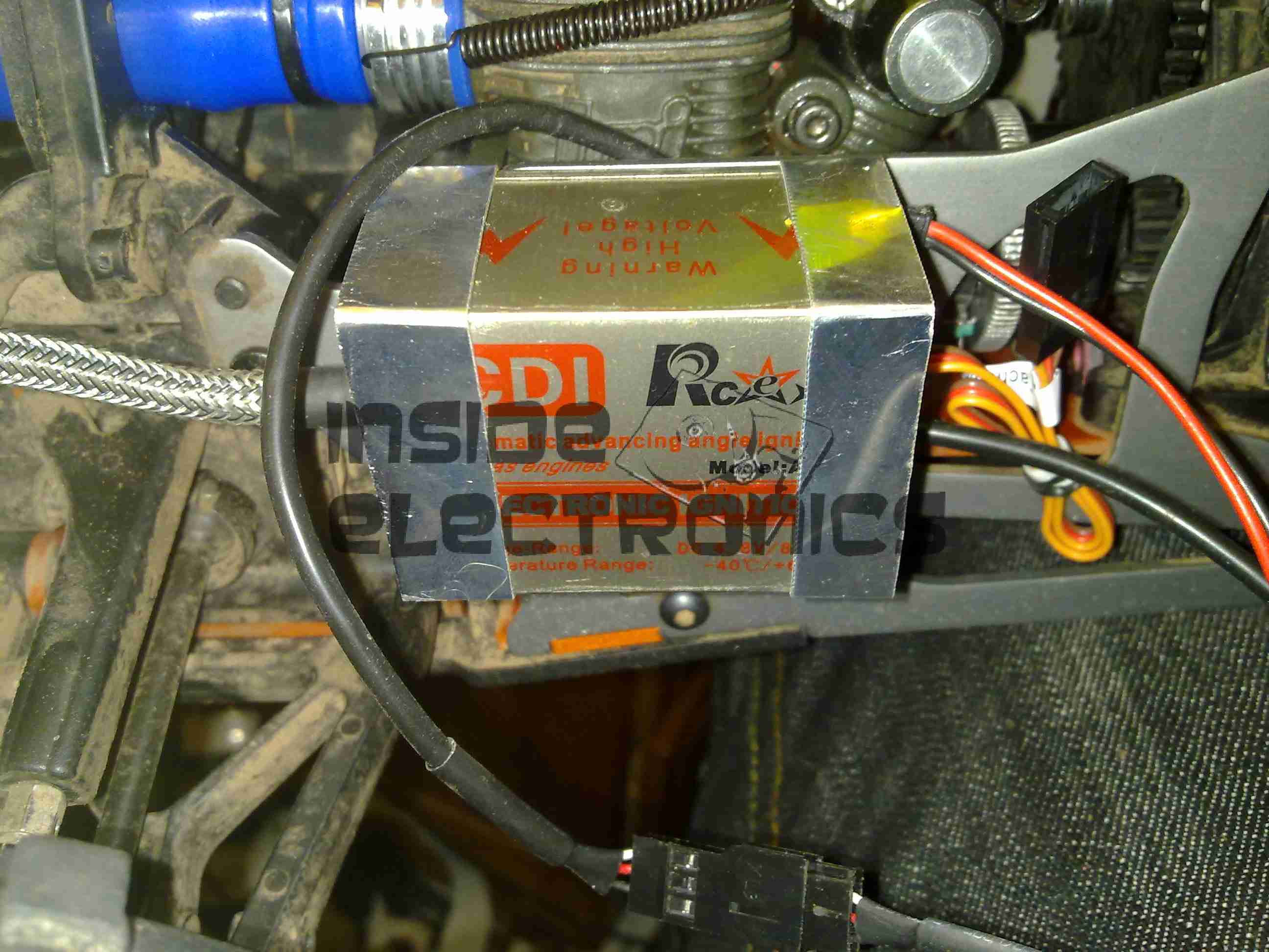
The engine now with it’s required ignition sensor, it is now mounted back on the chassis of the model. I have replaced the stock side exhaust with a rear silencer, so I could fit the ignition module in place next to the engine.
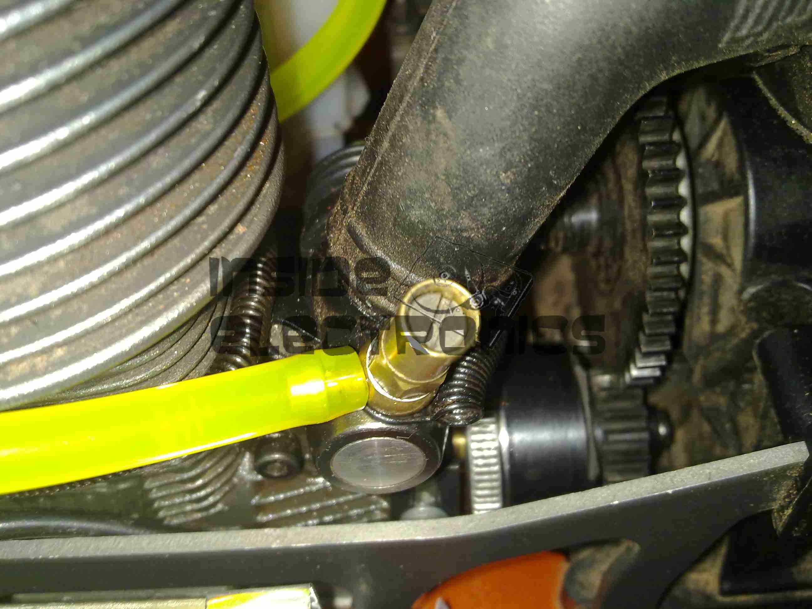
For the mounting, I fabricated a pair of brackets from 0.5mm aluminium, bent around the module & secured with the screws that attach the engine bed plate to the TVPs. The ignition HT lead can be routed up in front of the rear shock tower to clear all moving suspension parts, with the LT wiring tucked into the frame under the engine.
In this location the module is within the profile of the model chassis so it shouldn’t get hit by anything in service.
Rear Exhaust
New exhaust silencer fitted to the back of the model. This saves much space on the side of the model & allows the oily exhaust to be discharged away from the back wheel – no more mess to wipe up.
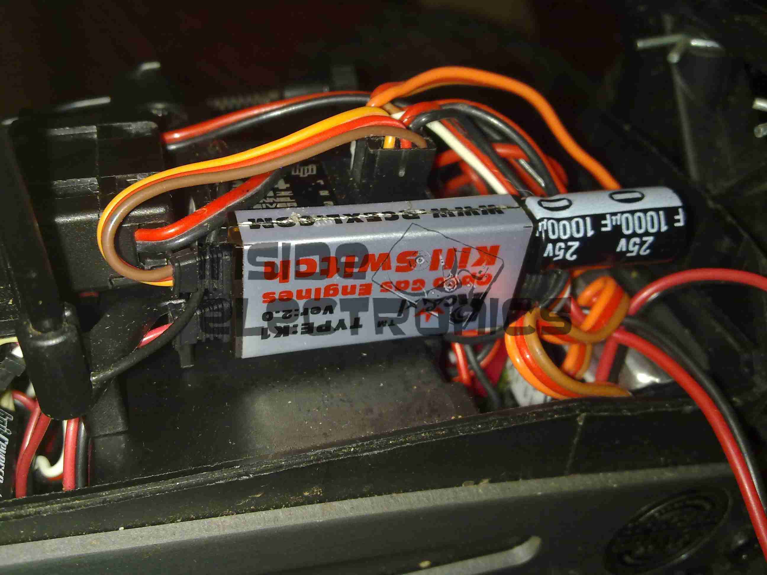
Kill Switch
The ignition switch fitted into the receiver box. This is wired into channel 3 of the TF-40 radio, allowing me to remotely kill the engine in case of emergency. I have fitted a 25v 1000µF capacitor to smooth out any power fluctuations from the ignition module.
The radio is running from a 11.1v 1Ah 3S LiPo pack connected to a voltage regulator to give a constant 6.5v for the electronics. I found this is much more reliable than the standard 5-cell Ni-MH hump packs.
Fuel Tank
The stock silicone fuel tubing has been replaced with Tygon tubing to withstand the conversion to petrol.
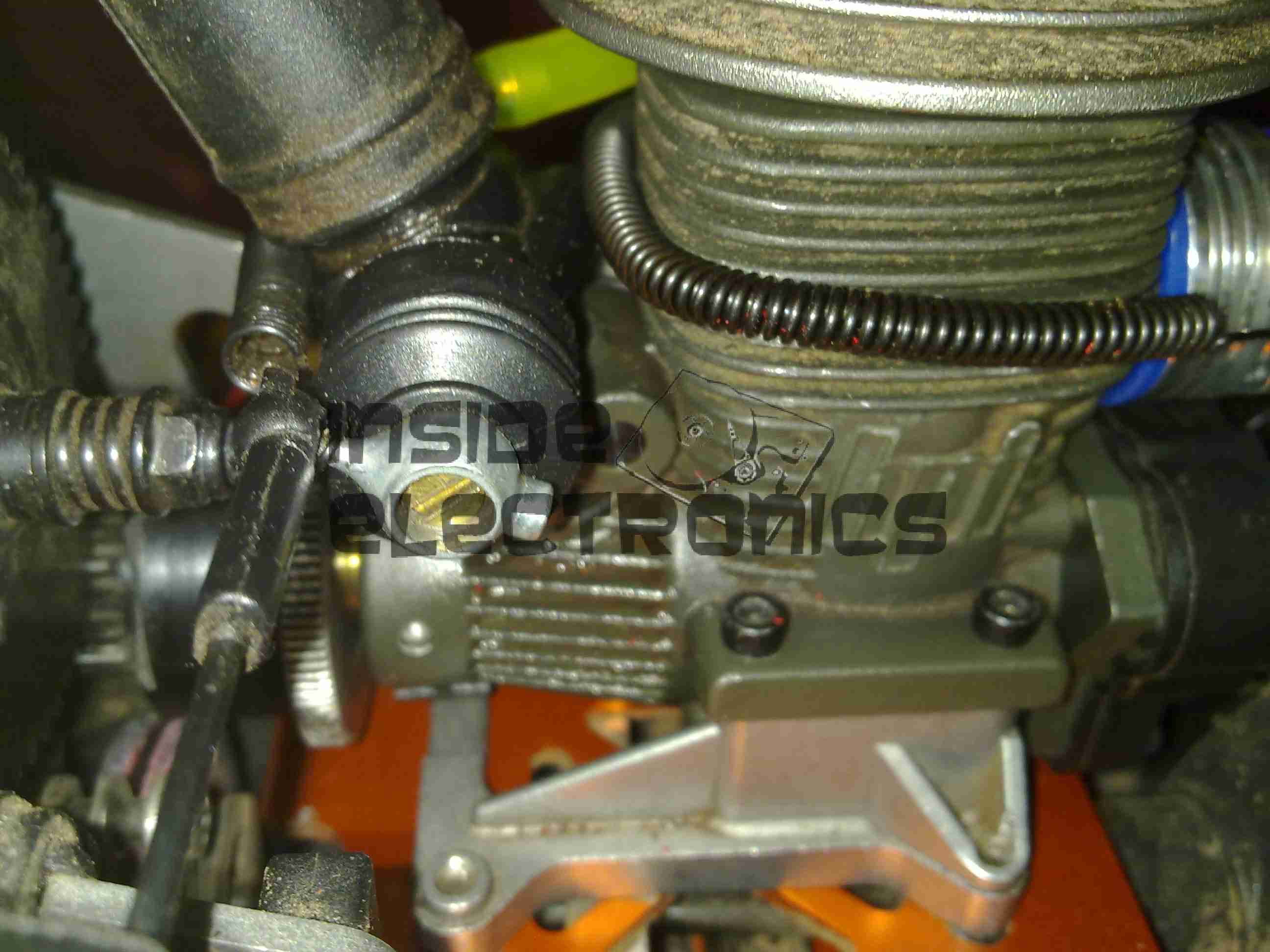
High Speed Needle
High speed needle tweaked to provide a basic running setting on petrol. This is set to ~1.5mm below flush with the needle housing.
Low Speed Needle
Low speed needle tweaked to provide a basic running setting on petrol. This is set to ~1.73mm from flush with the needle housing.
As petrol is a much higher energy density fuel, it requires much more air than the methanol glow fuel – ergo much leaner settings.
The settings listed should allow an engine to run – if nowhere near perfectly as they are still rather rich. It’s a good starting point for eventual tuning.
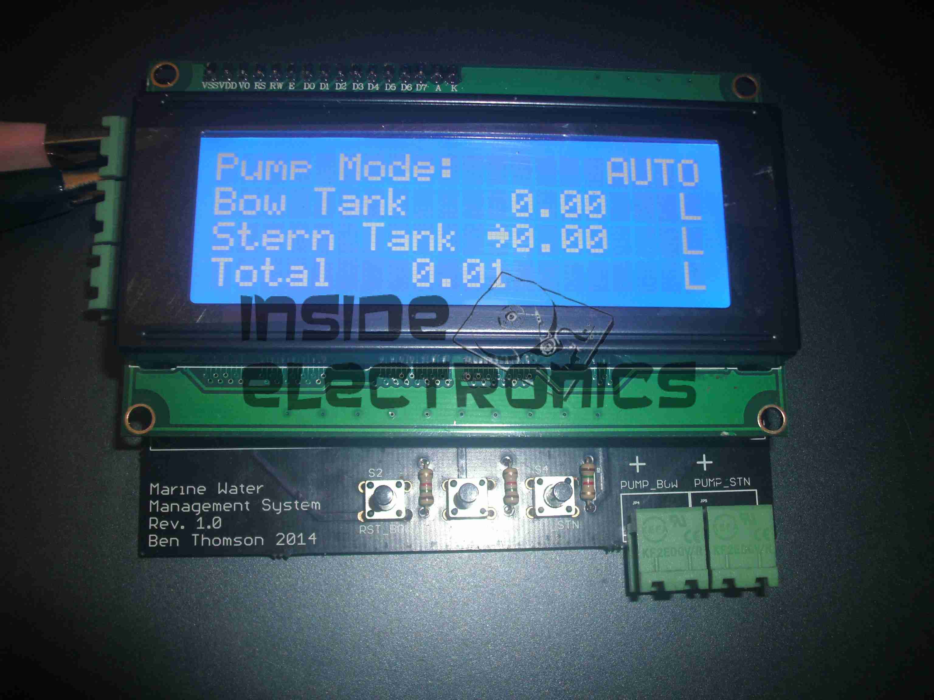
Having two separate water tanks on nb Tanya Louise, with individual pumps, meant that monitoring water levels in tanks & keeping them topped up without emptying & having to reprime pumps every time was a hassle.
To this end I have designed & built this device, to monitor water usage from the individual tanks & automatically switch over when the tank in use nears empty, alerting the user in the process so the empty tanks can be refilled.
Based around an ATMega328, the unit reads a pair of sensors, fitted into the suction line of each pump from the tanks. The calculated flow is displayed on the 20×4 LCD, & logged to EEPROM, in case of power failure.
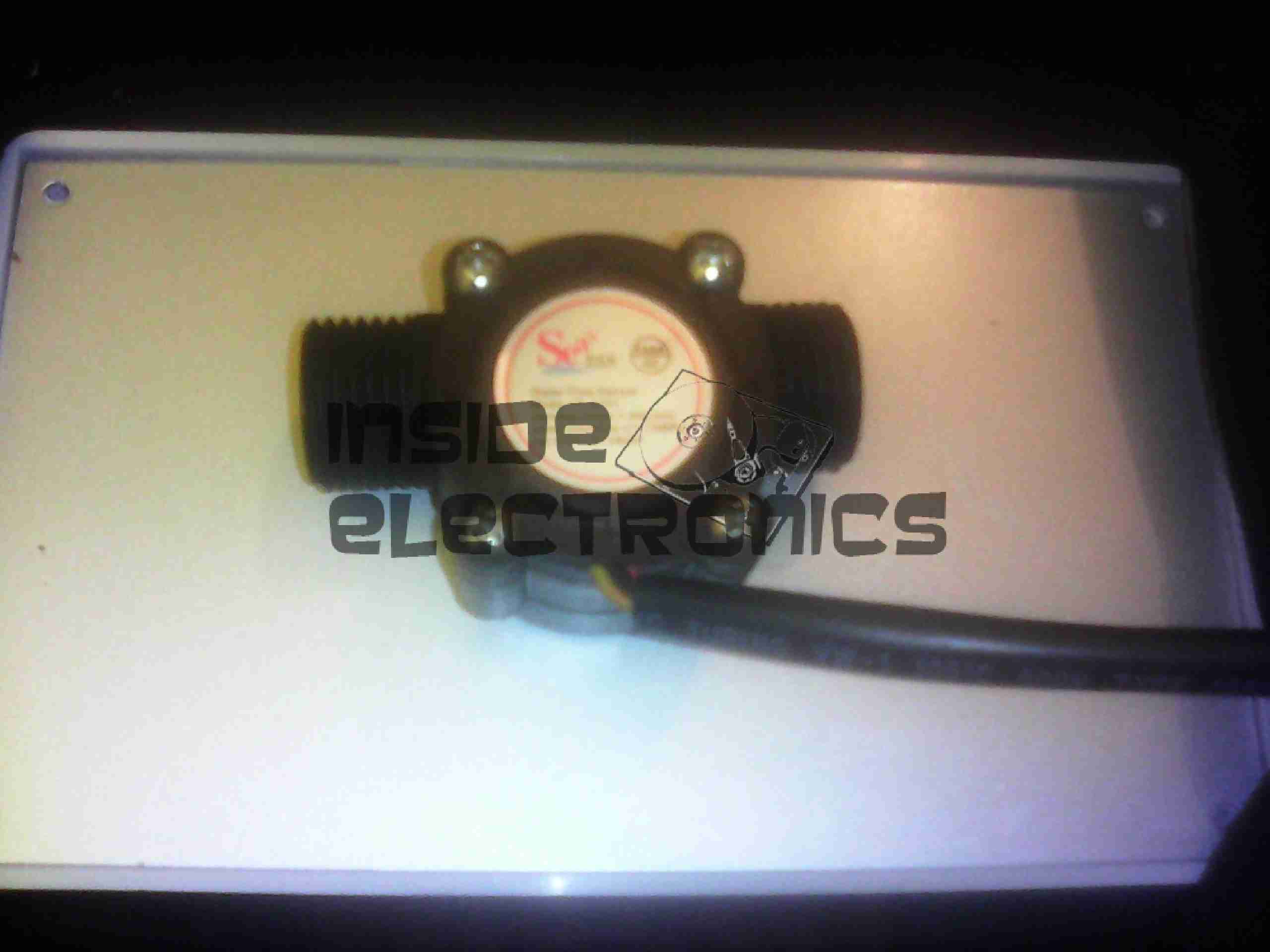
Water Flow Sensor
When the tank in use reaches a preset number of litres flowed, (currently hardcoded, but user input will be implemented soon), the pump is disabled & the other tank pump is enabled. This is also indicated on the display by the arrow to the left of the flow register. Tank switching is alerted by the built in beeper.
It is also possible to manually select a tank to use, & disable automatic operation.
Resetting the individual tank registers is done by a pair of pushbuttons, the total flow register is non-resettable, unless a hard reset is performed to clear the onboard EEPROM.
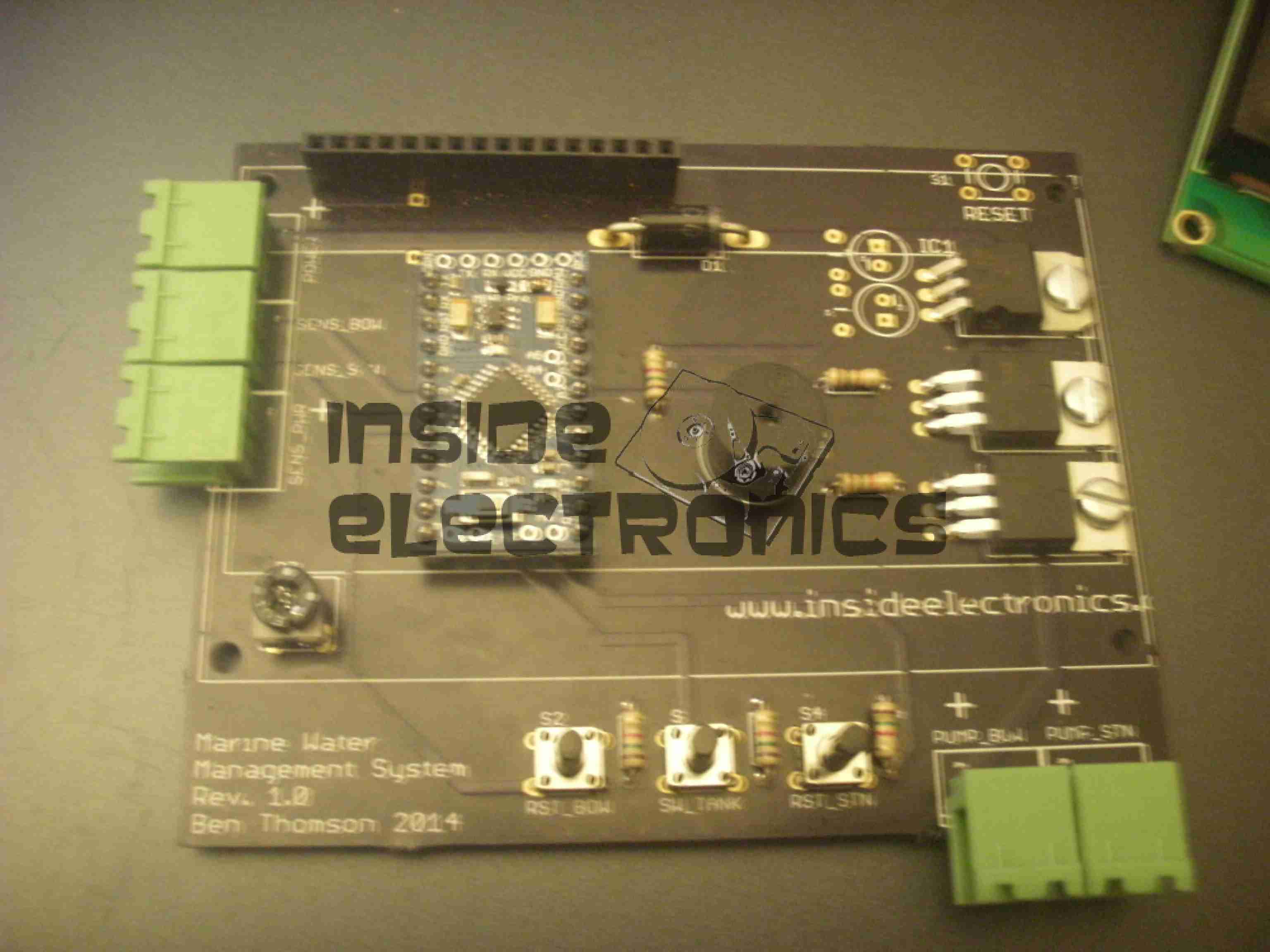
Main PCB
View of the main PCB is above, with the central Arduino Pro Mini module hosting the backend code. 12-24v power input, sensor input & 5v sensor power output is on the connectors on the left, while the pair of pump outputs is on the bottom right, switched by a pair of IRFZ44N logic-level MOSFETS. Onboard 5v power for the logic is provided by the LM7805 top right.
Code & PCB design is still under development, but I will most likely post the design files & Arduino sketch once some more polishing has been done.
The quickest project from inception to working PCB yet:
From inception to a working PCB took only 4 hours!
LM386 Amplifier
This is a miniature stereo audio amplifier, 0.5W per channel, that can be run from any voltage between 4-12v DC.
As usual, all the Eagle project files are available for download below & kits/bare PCBs will be available for sale for those that cannot etch boards.
In Operation
Here is the circuit driving a pair of 3W 8Ω speakers from a line level audio source. The gain of this circuit is set at 50 with the components specified.
Schematic
As can be seen from the schematic, this is a pair of single LM386 ICs for each channel.
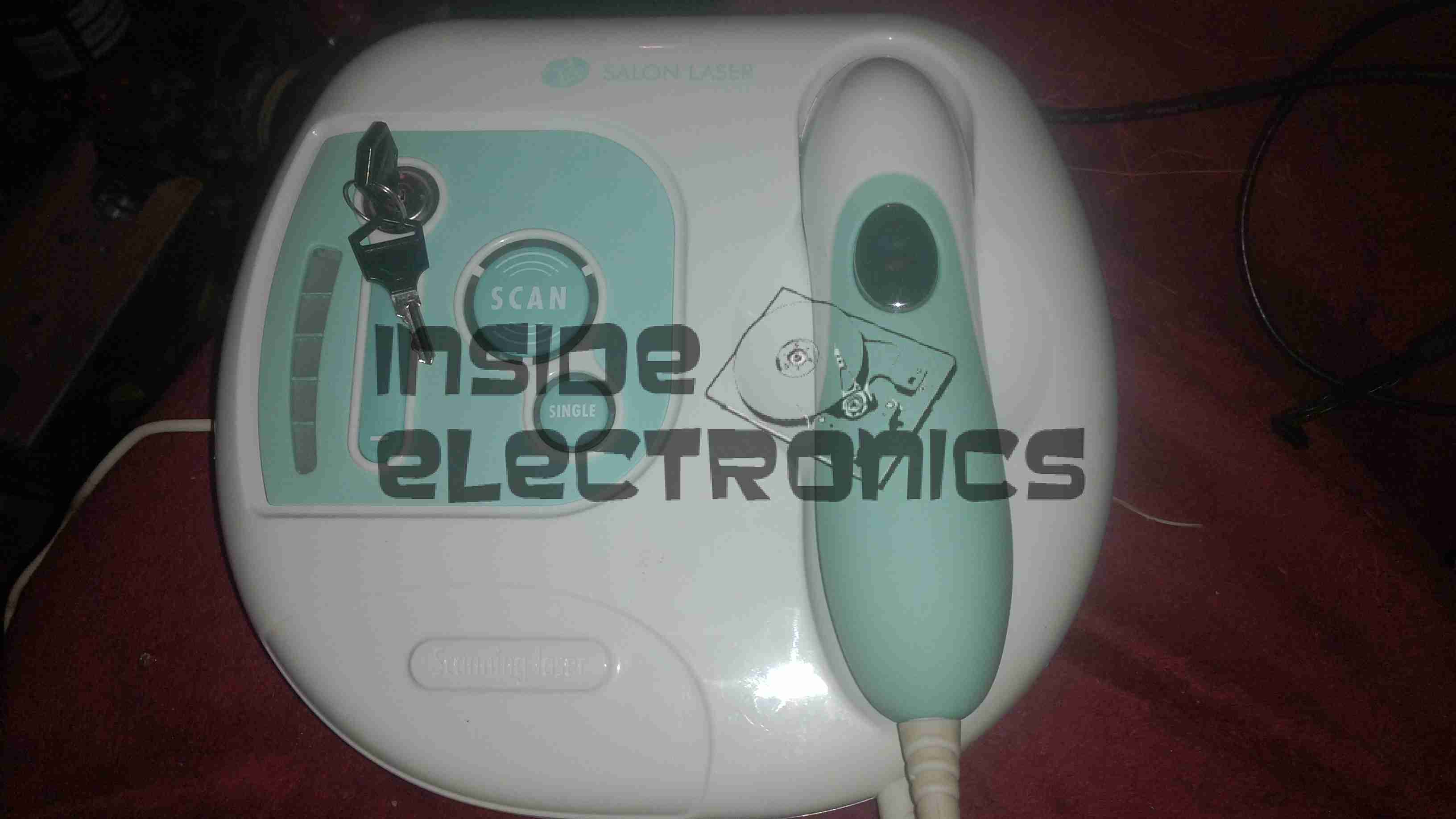
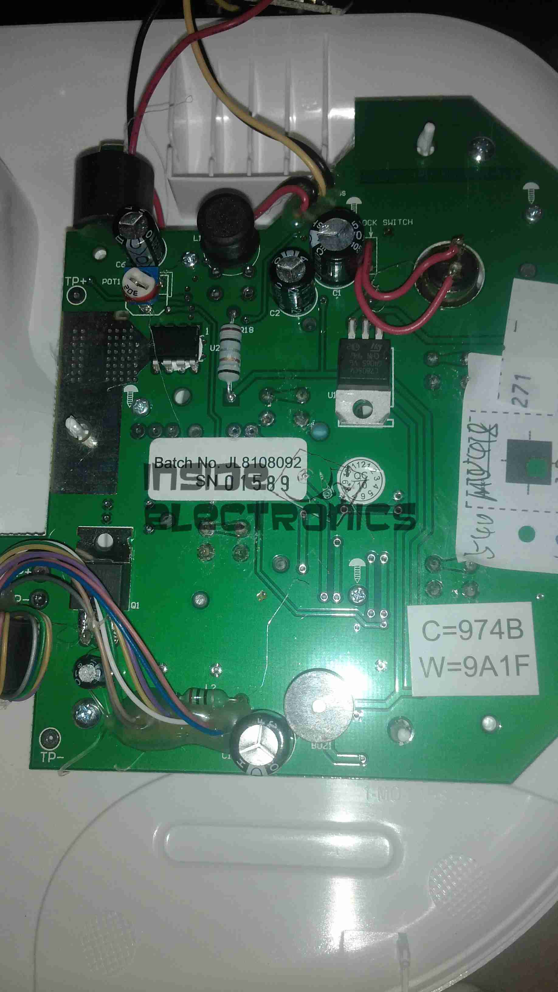
Here is a home laser hair removal unit, a Rio LAHS4. Shown above is the system overview, with the laser wand & the user controls.
Main PCB Top
Main base unit popped open reveals the main PCB, with the central processor, a PIC16F628A.
Main PCB Bottom
Other side of the PCB is mainly populated with power supply & filtering for the logic sections.
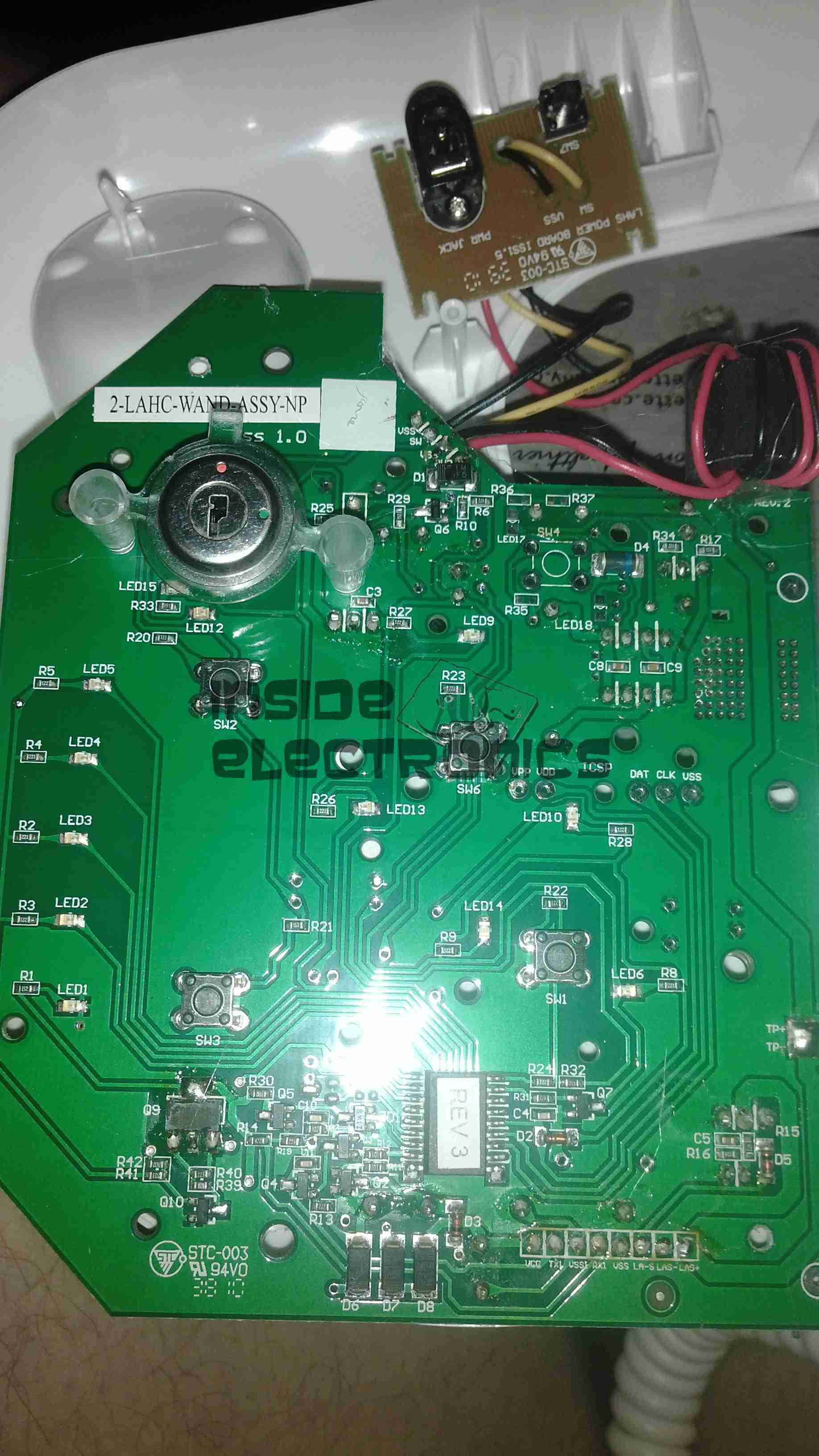
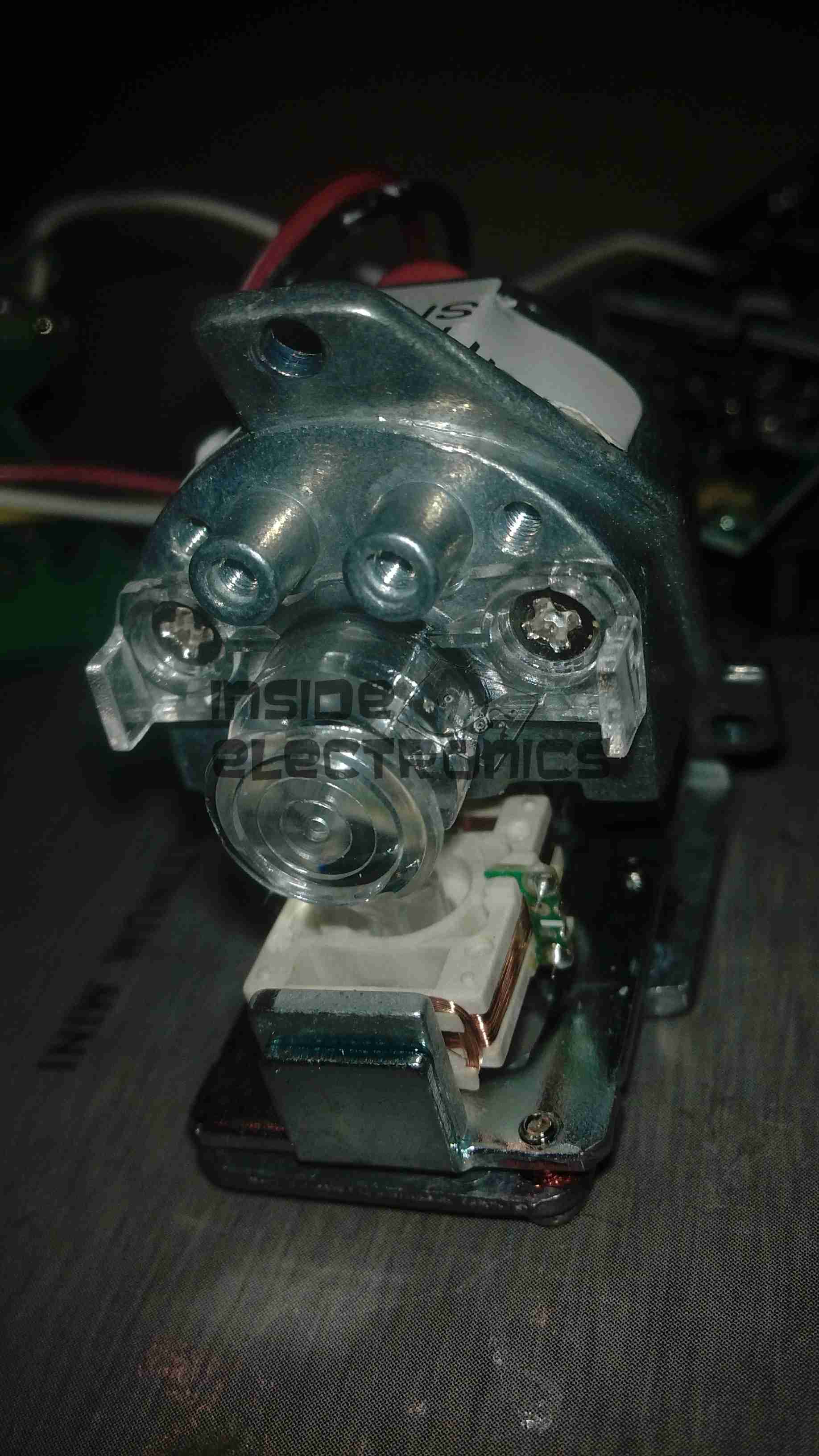
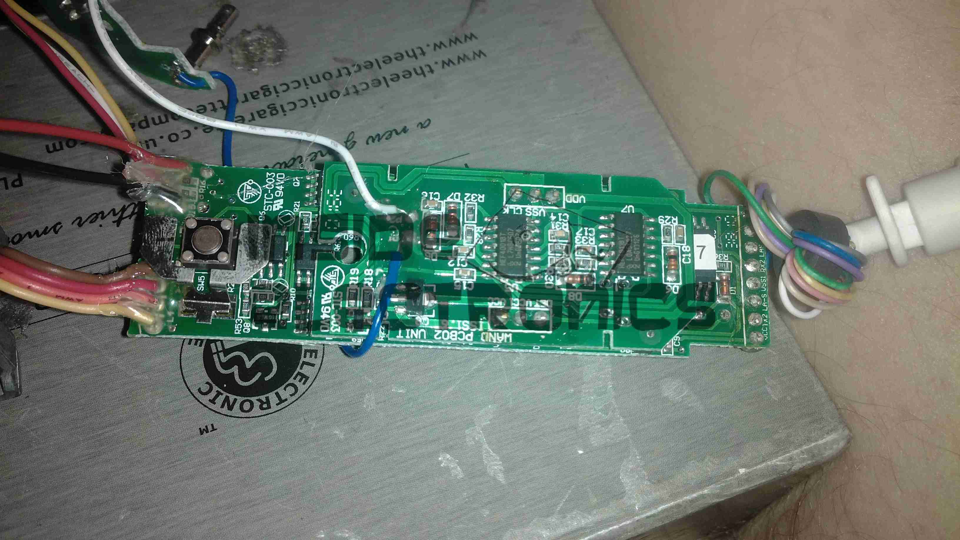
Wand PCB
Cracking open the laser wand reveals a stacked pair of PCBs, a main laser controller & the capacitive sensor PCB. This capacitive sensor connects to a pair of pins on the laser head & prevents operation if the unit is not held firmly against the skin.
Diode Module
Front of the laser diode module with the movable lens, on a pair of voice coil actuators. Very similar to the lens positioner used in any CD/DVD player pickup assembly.
The diode in this unit is an 808nm chip, with power in the 300-600mW range most likely.
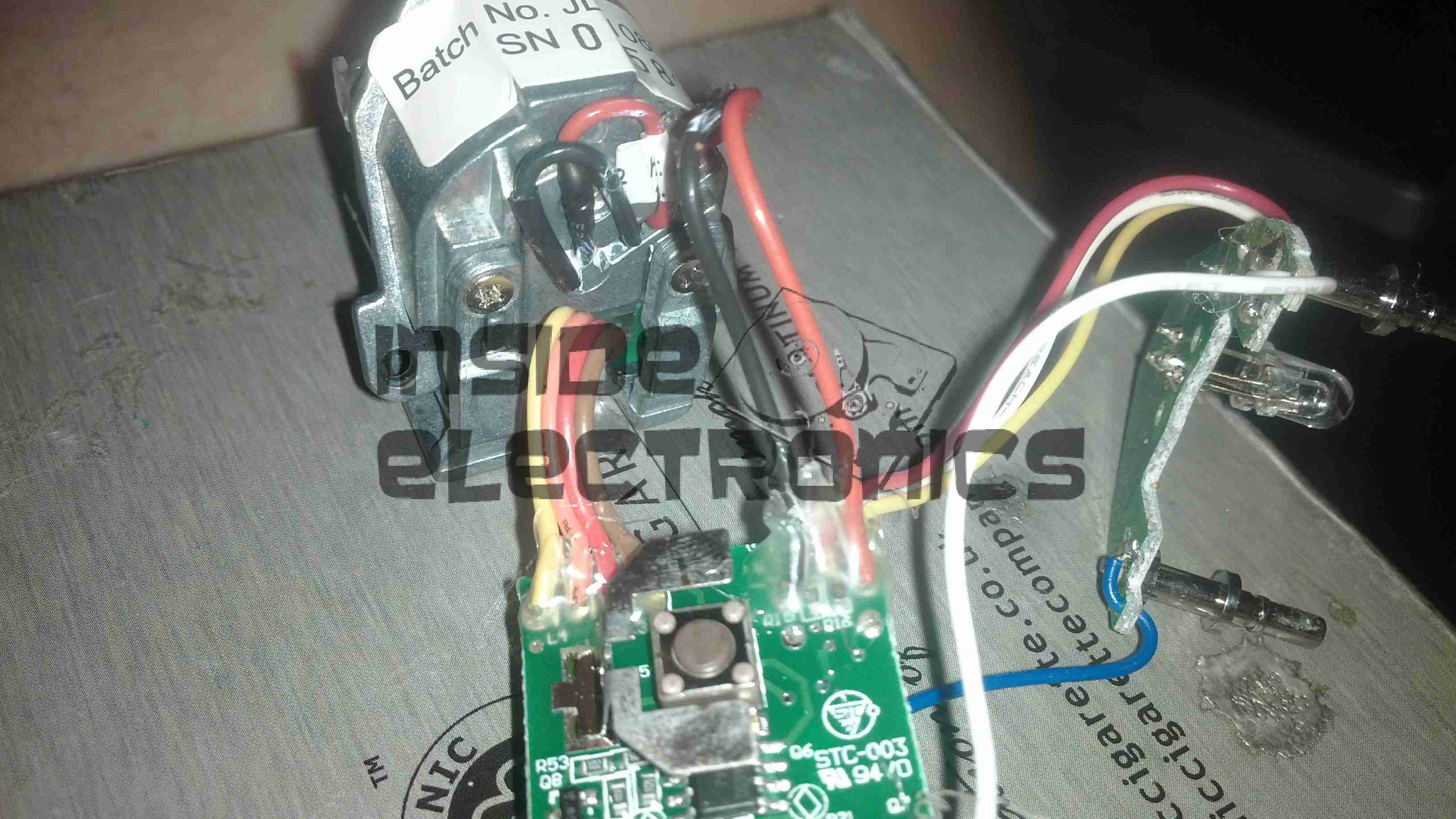
Diode Module Rear
Rear of the diode module, with the connections to the diode itself & the voice coil positioner for the lens.
Wand PCB Top
Other side of the wand PCB, showing the capacitive sensor board on top of the main controller board. There is another CPU on the board here, which most likely communicates with the main processor in the base through a serial connection.
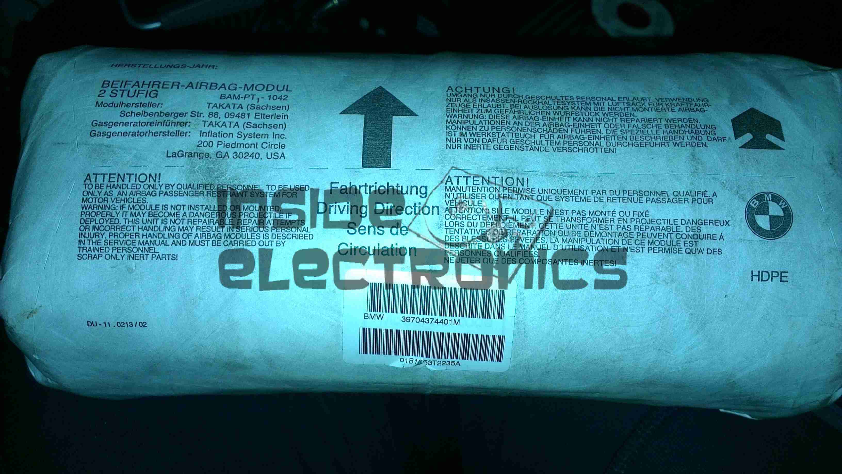
This is a passenger side airbag from a BMW vehicle. Here is the top of the device, with all the warning labels & information.
Folded Bag
Here the outer plastic wrap has been removed from the unit, showing the folded nylon fabric bag.
Frame
The base frame with the gas generator mounted.
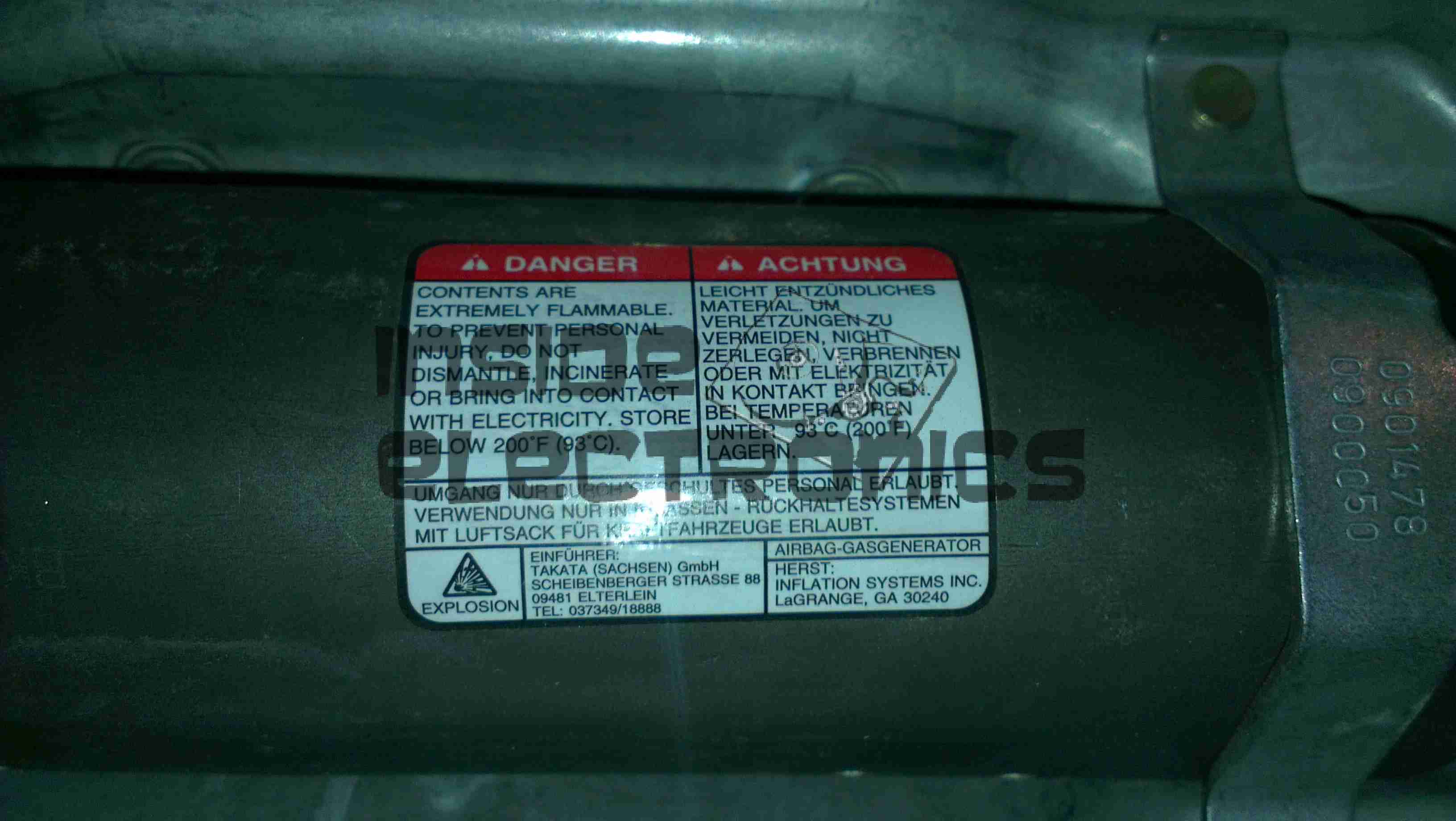
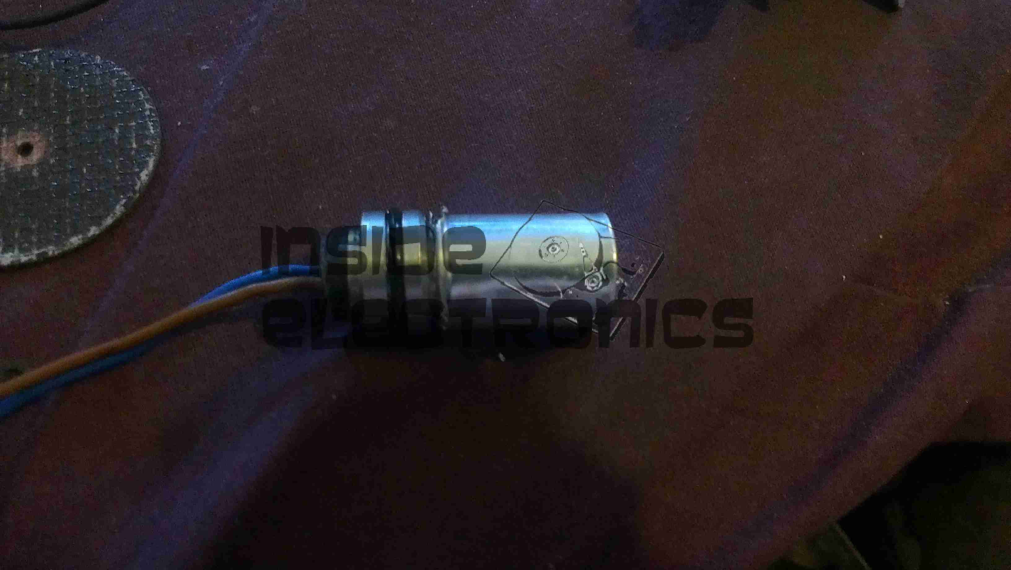
Gas Generator
Gas generator with warning label. This is a two part generator, with a pair of independent cores inside.
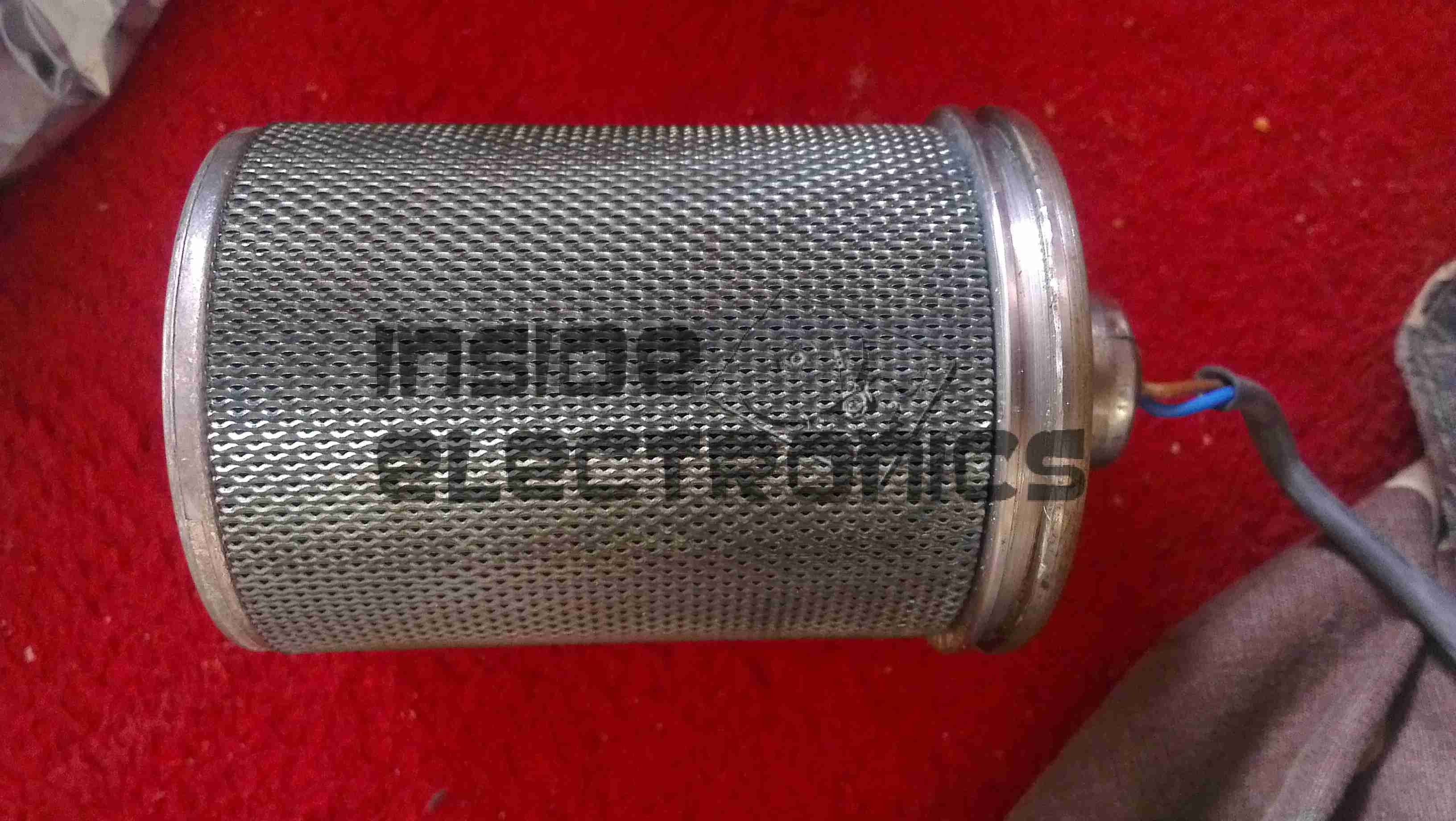
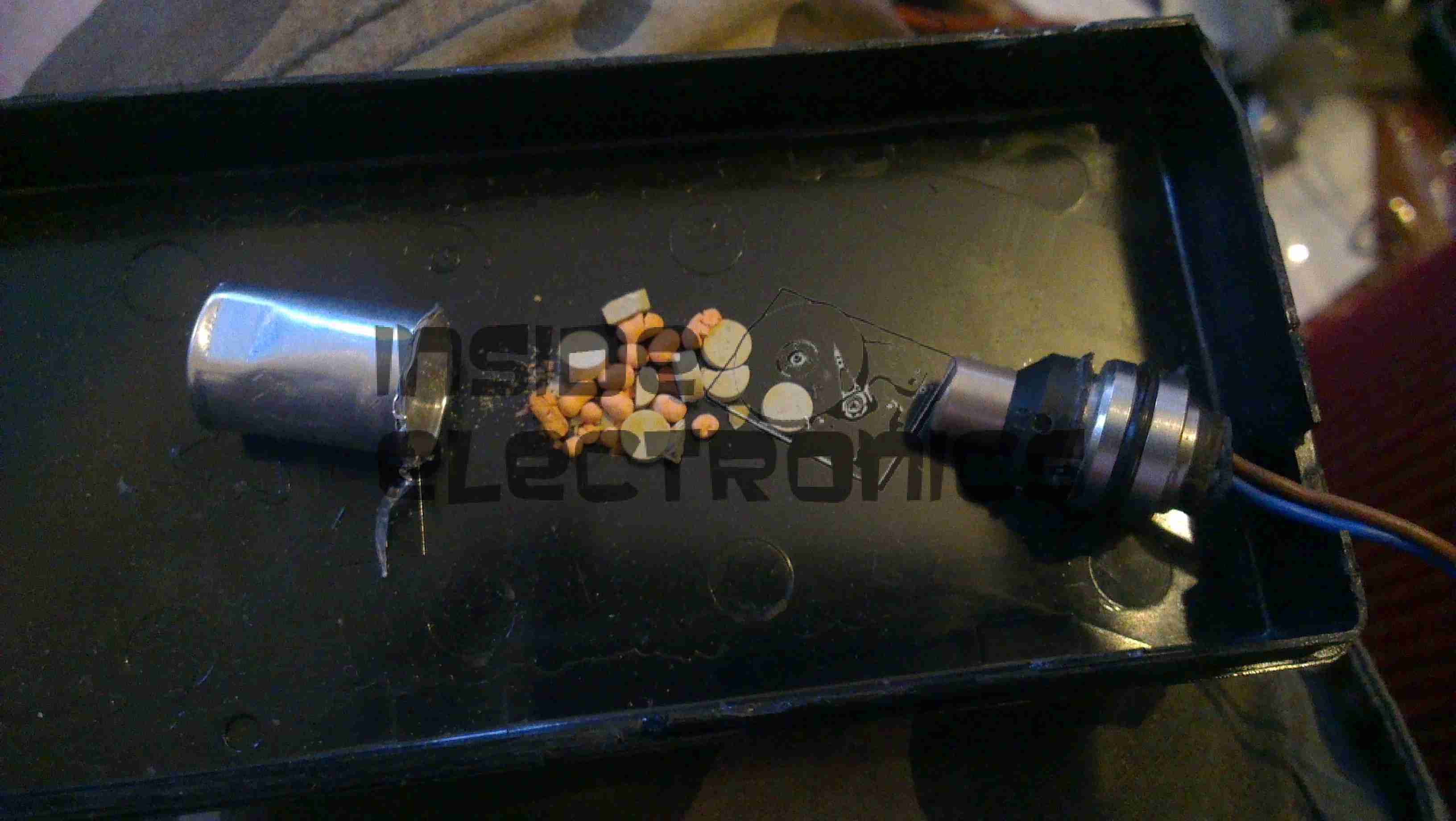
Generator Core
One of the generator cores removed from the heavy steel shell of the gas generator. The layers of wire mesh on the outside act as a flame trap, releasing only the gas generated from the burning propellant inside.
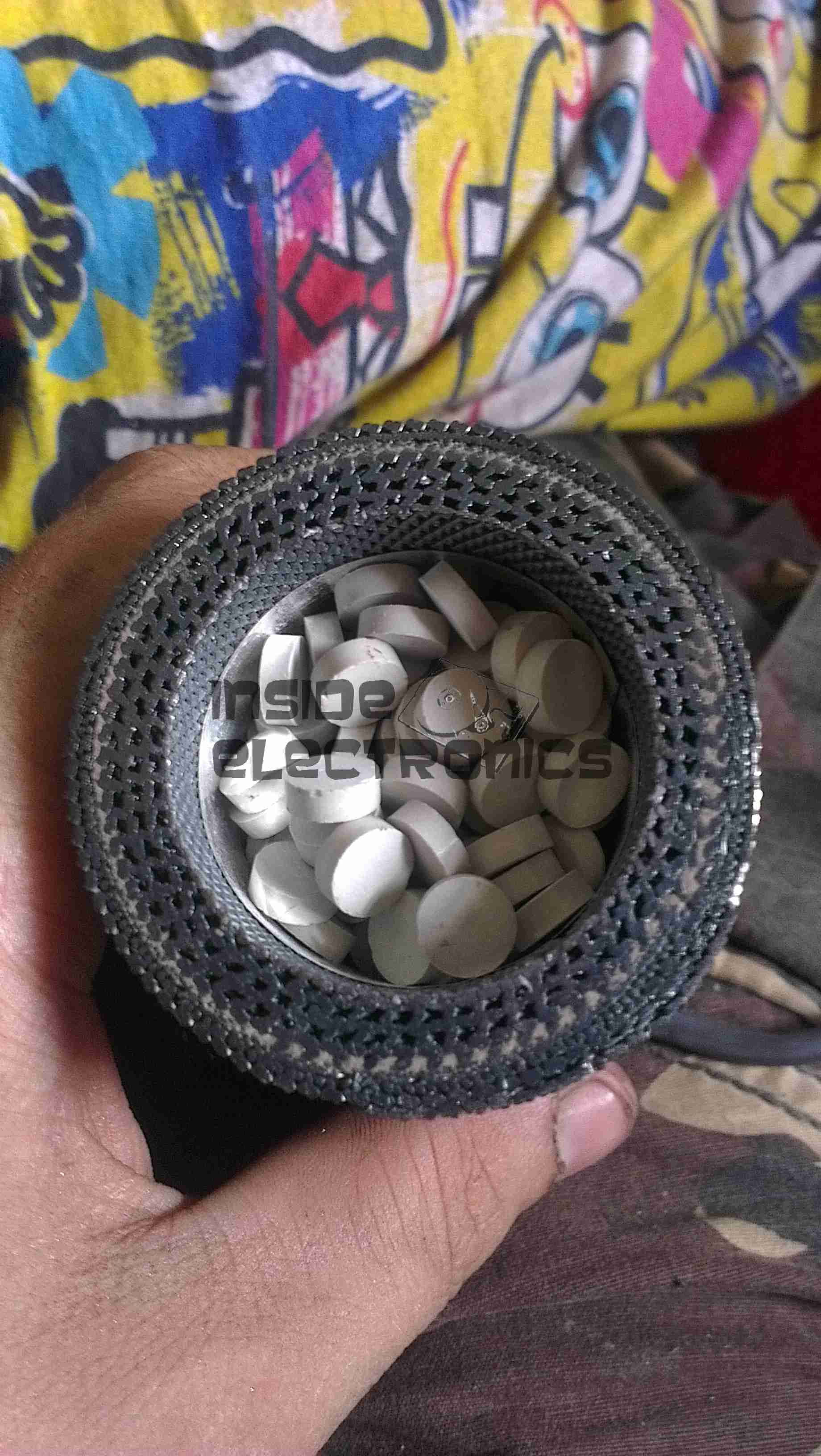
Propellant
End cap removed from the core, showing the pellets of propellant & the many layers of mesh & fibreglass filter material. The explosive initiator is in the bottom of this unit. A spring under the end cap firmly holds the pellets against the initiator.
Initiator
Finally, here is the explosive initiator that is located in the bottom of the core under the propellant pellets. This consists of a primary explosive & an electric match, which can be seen below as the device is disassembled.
Initiator Components
Tip Jar
If you’ve found my content useful, please consider leaving a donation by clicking the Tip Jar below!
All collected funds go towards new content & the costs of keeping the server online.