Posted on Leave a comment

Bosch GSR 14.4v Pro Drill-Driver

Drill Case
Drill Case

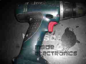
Here is a Bosch 14.4v Professional cordless drill/driver, recovered from a skip!
It was thrown away due to a gearbox fault, which was easy to rectify.
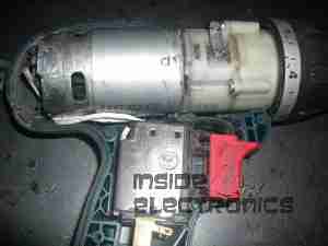
Internals
Internals

Here is the drill with the side cover removed, showing it’s internal parts. The speed controller is below the motor & gearbox here. The unit at the top consists of a 12v DC motor, coupled to a 4-stage  epicyclic gearbox unit, from which can be selected 2 different ratios, by way of the lever in the centre of the box. This disables one of the gear stages. There is a torque control clutch at the chuck end of the gearbox, this was faulty when found.
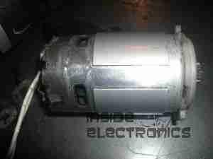
Motor
Motor

Here is the drive motor disconnected from the gearbox, having a bayonet fitting on the drive end.
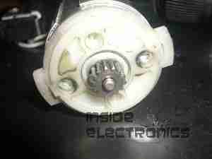
Drive Gear
Drive Gear

This is the primary drive gear of the motor, which connects with the gearbox.
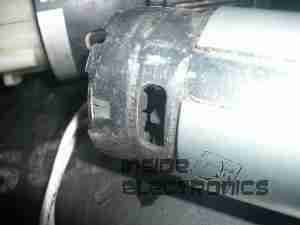
Cooling Fan
Cooling Fan

The motor is cooled by this fan inside next to the commutator, drawing air over the windings.
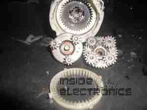
Gearbox
Gearbox

This is the gearbox partially disassembled, showing the 1st & second stages of the geartrain. The second stage provides the 2 different drive ratios by having the annulus slide over the entire gearset, disabling it entirely, in high gear. The annulus gears are a potential weak point in this gearbox, as they are made from plastic, with all other gears being made of steel.
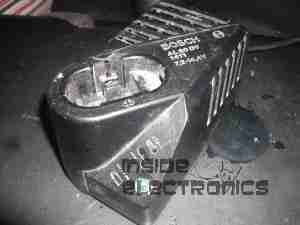
Charger
Charger

Here is the charging unit for the Ni-Cd battery packs supplied with the drill. The only indicator is the LED shown here on the front of the unit, which flashes while charging, & comes on solid when charging is complete. Charge termination is by way of temperature monitoring.
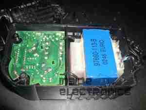
Transformer
Transformer

Here the bottom of the charger has been removed, showing the internal parts. An 18v transformer supplies power to the charger PCB on the left.
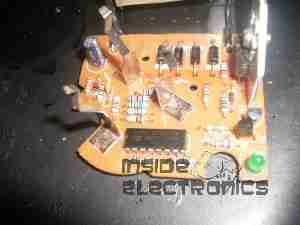
Charger PCB
Charger PCB

This is the charger PCB, with a ST Microelectronics controller IC marked 6HKB07501758. I cannot find any information about this chip.
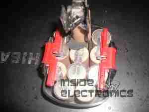
Battery Pack Internals

Here is a battery pack with the top removed, showing the cells.
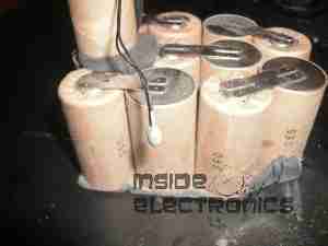
Temperature Sensor
Temperature Sensor

This is the temperature sensor embedded inside the battery pack that is used by the charger to determine when charging is complete.

Posted on Leave a comment

Dremel MultiPro

Front
Front

Here we have a Dremel MultiPro rotary tool, a main powered 125W 33,000RPM bit of kit.

Motor Assembly
Motor Assembly

Here the field & controller assembly is removed from the casing.

Armature
Armature

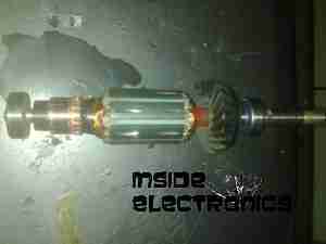
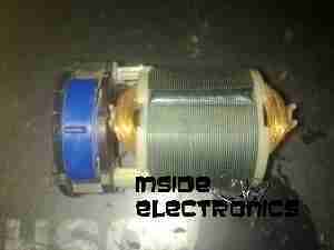
Here is the armature, which rotates at up to 33,000RPM. The brushes rise against the commutator on the left, next to the bearing, the cooling fan is on the right hand side on the power output shaft, the chuck attaches at the far right end of the shaft.

Speed Controller & Brush Box

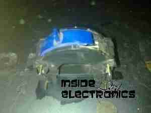
Here is the speed controller unit, inside is an SCR phase angle speed controller, to vary the speed of the motor from 10,000RPM to the full rated speed of 33,000RPM.

Mains Filter
Mains Filter

This is the mains filter on the input to the unit, stops stray RF from the motor being radiated down the mains cable.

Posted on Leave a comment

Hair Dryer

Housing
Housing

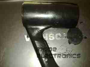
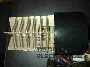
This is a 1500W hairdryer, death caused by thermal switch failure.

Switch
Switch

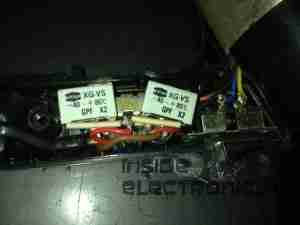
This is the switch unit. Attached are two suppression capacitors & a blocking diode. Cold switch is on right.

Heating Element
Heating Element

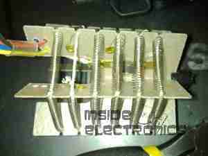
Heating element unit removed from housing. Coils of Nichrome wire heat the air passing through the dryer. Fan unit is on right.

Thermal Switch
Thermal Switch

Other side of the heating element unit, here can be seen the thermal switch behind the element winding. (Black square object).

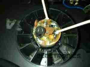
Fan Motor
Fan Motor

The fan motor in this dryer is a low voltage DC unit, powered through a resistor formed by part of the heating element to drop the voltage to around 12-24v. Mounted on the back of the motor here is a rectifier assembly. Guide vanes are visible around the motor, to straighten the airflow from the fan blades.

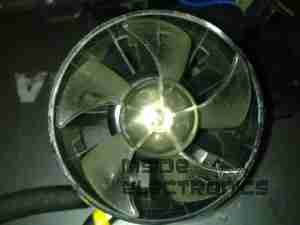
Fan
Fan

5-blade fan forces air through the element at high speed. Designed to rotate at around 13,000RPM.

Posted on Leave a comment

Western Digital 160GB 2.5″ HDD

Top Of Drive With Label
Top

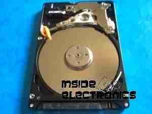
This is a Western Digital drive recently removed from my laptop when it died of a severe head crash.
Top of drive can be seen here.

Top Removed From Drive
Top Removed

Here the cover has been removed from the drive, showing the platter, head arm & magnet. Yellow piece top left is head parking ramp.

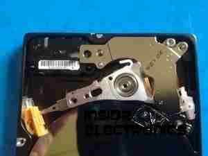
Head Arm of Drive
Head Arm

The head assembly of the drive is shown here. The head itself is on the left hand end of the arm in the plastic parking ramp. The other end of the arm holds the voice coil part of the head motor, surrounded by the magnet.

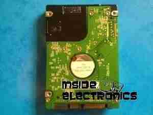
Bottom Of Drive with PCB

Bottom of drive, with controller PCB. SATA interface socket at bottom.

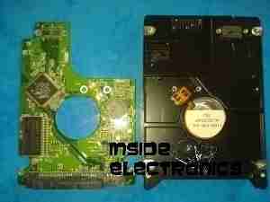
PCB removed from bottom of drive. Spindle motor connections & connections to the head unit can be seen on the bottom of the drive unit.

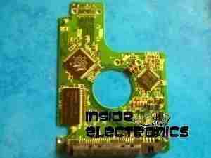
Controller PCB. Supports the cache, interface & motor controller ICs.

Closeup of the motor driver IC, this controls the speed of the spindle motor precisely to 5,400RPM. Also controls the voice coil motor controlling the position of the head arm on the platters.

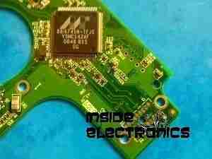
Interface IC closeup. This IC receives signals from the head assembly & processes them for transmission to the SATA bus. Also holds drive firmware, controls the Motor driver IC & all other functions of the drive.

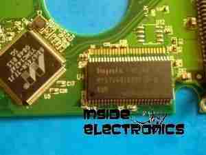
Cache Memory IC.