Posted on Leave a comment

Motorola V360v

Front
Front

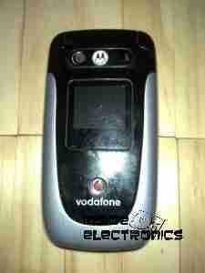
Here is a more modern phone, the Motorola V360v. Features include Dual screens, 640×480 VGA camera, full col

our TFT Main LCD, SD-Micro slot.
Here on the back the grey scale LCD can be seen, with the camera lens to the right of the Motorola logo
Keypad
Keypad

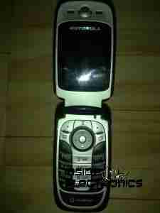
Here the phone is opened showing the keypad & the full colour TFT LCD display.
Battery Compartment
Battery Compartment

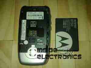
Here the battery is removed from the unit, showing the SIM connector. The antenna cover is still on at the bottom.
Antenna
Antenna

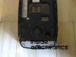
The antenna cover has been removed in this shot, the antenna is the white section at the bottom, With the loudspeaker & the external antenna connector hidden at the right.
PCB
PCB

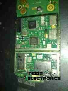
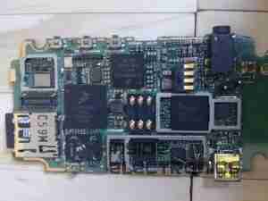
Here is the main PCB. Parts from left are the Bluetooth module at the top, supplied by Broadcom, the SD Card socket at the bottom. Main CPU next to that is the Freescale SC29343VKP. Above right of the CPU is the Freescale SC13890P23A Charger, Power & Audio IC. Below is the SIM card socket. Under the main CPU is the Intel Flash memory IC. ICs inside the shields are the RF sections for transmit & receive.
Cover Removed
Cover Removed

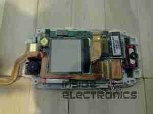
Rear of the display unit showing the monochrome LCD. The camera module on the bottom left. Ear speaker on the far right of the unit.
Main LCD
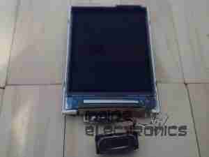
Main LCD

Main colour TFT LCD.

Camera
Camera

Camera module removed from the LCD unit.
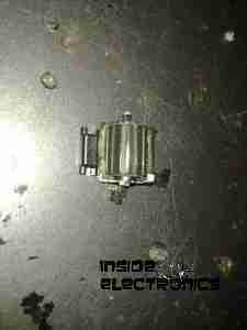
Vibra-Motor
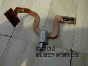
Vibra-Motor

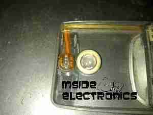
The vibration motor attached to one of the LCD looms.
Posted on Leave a comment

Nokia 7110

Front
Front

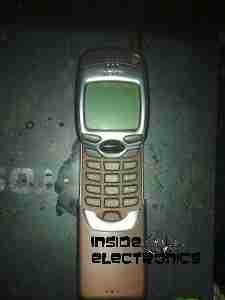
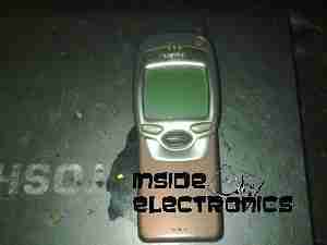
Another phone from the mid 90s. This is the nokia 7110.

Slider Open
Slider Open

Here the slider is open showing the keypad.

Battery Removed
Battery Removed

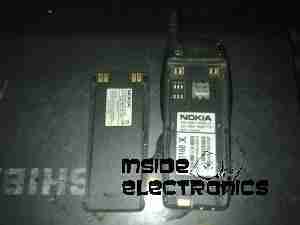
Here the battery is removed, a Li-Ion unit.

Battery
Battery

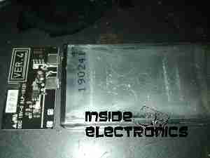
The battery cell & protection circuit removed from the casing.

Rear Of PCB
Rear Of PCB

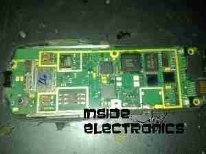
This is the rear of the PCB removed from the housing. Data & charging ports on the right hand side f the board.

Front Of PCB
Front Of PCB

Front of the PCB with the RF sections at the left hand side & the keypad contacts on the right.

RF Sections
RF Sections

Closeup of the RF sections of the board, big silver rectangular cans are VCO units.

SIM Connector
SIM Connector

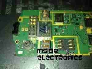
Closeup of the top rear section of the PCB, with SIM cnnector, battery contacts, IR tranciever at the far left. Bottom centre is the external antenna connector.

CPU
CPU

The logic section of the board, Large chip is CPU, to right of that is the ROM storing the machine code. Other chips are unknown custom parts.

Mic & Speaker
Mic & Speaker

The Mic & the loudspeaker removed from it’s housing.

LCD
LCD

LCD from the front of the unit, SPI interfaced. Flex PCB also contains the power button, loudspeaker contacts & a temperature sensor.

Scroll Wheel
Scroll Wheel

The scroll wheel removed from the front housing.

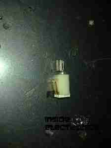
Vibra-Motor
Vibra-Motor

Tiny vibration motor removed from the rear housing, alerts the user to a text or phone call.

Posted on Leave a comment

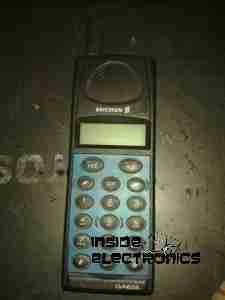
Ericsson GA628

Front
Front

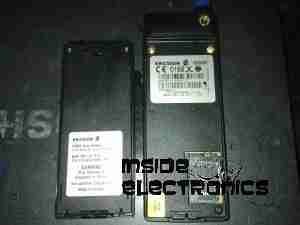
Here is a phone from the mid 90s, the Ericsson GA628. Here visible is the front of the unit with keypad, & single line monochrome LCD for number display.

Battery & Rear
Battery & Rear

Here the battery is removed from the phone, showing the SIM card socket. At the top under the antenna stub is the socket for an external antenna.

Front Removed
Front Removed

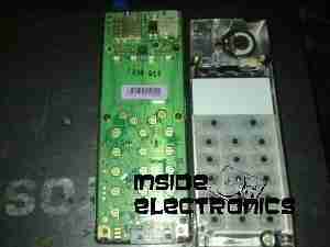
Here the front is removed from the phone, PCB on left, rear of keypad on right. Microphone is at bottom of keypad, with speaker at the top. Top right of the PCB is the ringer buzzer, left is shield for RF amplifier.

Main PCB
Main PCB

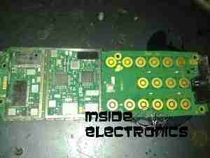
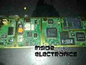
Here is the back of the main PCB, RF sections on left & centre. Processing & memory on right.

Battery
Battery

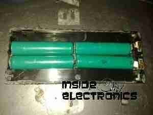
This phone had a Ni-Mh battery, before Li-Ion batteries were introduced.

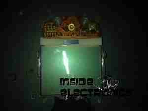
LCD
LCD

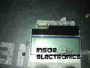
The LCD from the front of the phone is shown here. A simple dot matrix single line unit.

Posted on 2 Comments

Current Cost ‘Envi’ CC128 Power Meter

Display Unit
Display Unit

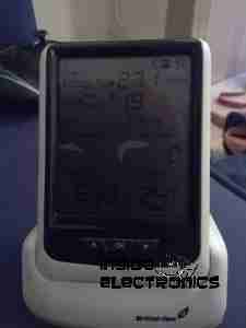
This is the Current Cost CC128 Real Time Power Meter. Shown here is the display unit, British Gas issued these free to some customers.
This unit measures current power draw in Watts, cost of power currently being used (requires unit price to be set), overall kWh usage over the past 1, 7 or 30 days & power trends during the day, night & evening. Also displays current time & current room temperature.

Display PCB
Display PCB

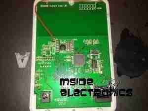
Here the front panel of the display has been un-clipped. At the bottom are the RJ-45 serial port & power connections.
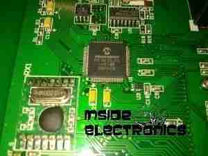
This unit uses a PIC micro-controller as it’s CPU (PIC18F85J90) Just above & left of the CPU is the 433MHz SPD radio receiver module. The chips on the right of the CPU are a 25LC128 SPI serial EEPROM for data storage & a 74HC4060 14 stage binary counter, to which is connected the 32kHz clock crystal. The red wire around the top of the display is the antenna for the radio receiver.

For more info on the CC128 in general, the serial port & software for computer data logging, see this link
See this link for Current Cost’s list of software

Processor & Radio
Processor & Radio

Closeup of the ICs on the mainboard.

Transmitter Unit
Transmitter Unit

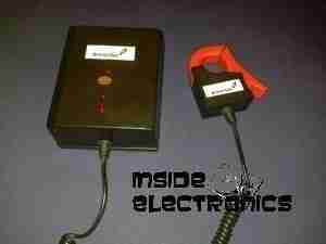
Here we have the transmitter unit, with Current Transformer (CT). The red clamp fits around one of the electric meter tails & read the current going to the various circuits. This unit is powered by 2x D cells, rated at a life of 7 years.

Transmitter PCB
Transmitter PCB

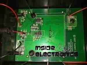
The PCB inside the transmitter. Again very minimal design, unknown controller IC, 433MHz radio transmitter on right hand side with wire antenna. Two barrel connectors on left hand side of board allow connection of up to two more CT clamps for measurement of 3-phase power. Centre of board is unmarked header. (ICSP?)

Current Transformer
Current Transformer

CT unit. Inside is a coil of wire & an iron core which surrounds the cable to be measured.