Posted on Leave a comment

BigBen DSi Inductive Charging Dock

Front
Front

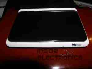
Here is a Inductive charger designed for the Nintendo DSi. Cheap Chinese build, but it does work!

Overview
Overview

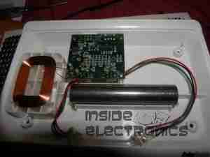
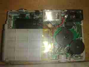
Top has been removed from the unit here. Most prominent in the centre is a solid steel bar, simply there to give the device some weight.
Pair of Tri-colour LEDs at the front indicates charging status.
Induction coil is on the left, with the controller & oscillator PCB at the top.

PCB Closeup
PCB Closeup

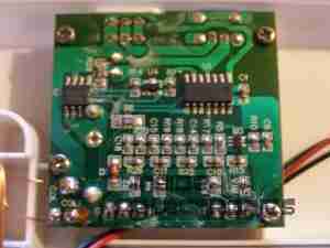
Closeup of the PCB, ICs have had their markings ground off.

Coil
Coil

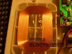
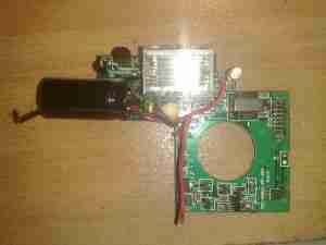
Induction coil. This couples power into a coil built into a special battery, supplied with the base, to charge it when the DSi is placed on the dock.

Label
Label

Information Label on the base.

Power Input
Power Input

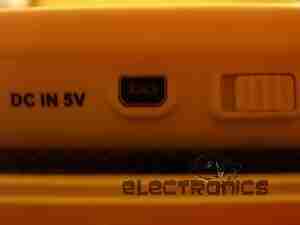
Standard DSi charger port, connects to the charger you get with the DSi. Power switch is on the right.

Posted on Leave a comment

The Truth About DWP Cuts From A DWP Worker On The Front Line

A bit of a shift from my usual content, but I thought this deserved a place for people to see. Only relevant for people of the UK though.

“I’m a DWP worker sticking his head above the parapet and hoping not to get shot…

I work in a busy Jobcentre and my customers are those 25+ who’ve been out of work for 13 weeks or longer. Probably 60-70% of the one hundred or more people I see every week [who] are evidently not fit for work and yet, in theory, it’s my job to whip them through the same hoops as everybody else, persecute them, attempt to stop their benefits and generally shame them into applying for all manner of wholly unsuitable jobs that they’re never going to be able to do.

In reality, what I do is tell them the system sucks and advise them of ways they can stay beneath the radar, or suggest they sign off JSA and move onto ESA and do whatever I can to make the transition as trouble free as possible.

On the other side of the office to me are the Pathways team, who deal with customers on ESA. We all know that over the coming months most of them will be forced to migrate over to the JSA bods like myself and we won’t be able to cope with either the numbers or the particular problems that this customer group represents.

The point of all this waffle is that the policy makers have embarked upon their catastrophic journey without consulting the frontline workers who, without exception in my experience, KNOW that the planned changes CANNOT work.

I would advise people worried about a forced transition from ESA to JSA to be brave and try not to lose too much sleep about it… It’s just not do-able in the real world, there’ll be a horrible mess and people’s lives will face some awful but shortlived disruption and then it’ll be business as usual.

Also, for those who face the indignity of having to venture into a jobcentre from time to time, please be assured – the majority of those who work in them are actually on your side, and have probably less faith in our political masters than you do, and just as much awareness as yourselves that all their vitriolic guff about benefit scroungers and feckless layabouts is simply empty, venomous scapegoating…”


Please feel free to copy and paste this to your own notes/blog, etc. Spread the truth.
Posted on Leave a comment

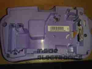
Brother P-Touch 80 Label Maker

Touchpad
Touchpad

Here is a label maker, bought on offer at Maplin Electronics. Full Qwerty keyboard with 1 line dot matrix LCD display visible here. Power is 4 AAA cells or a 6v DC Adaptor.

Rear
Rear

Rear cover removed. Battery compartment is on the left hand side, space for the tape cartridge on the right. Ribbon cable leading to the thermal print head is on the far right, with rubber tape drive roller.

PCB
PCB

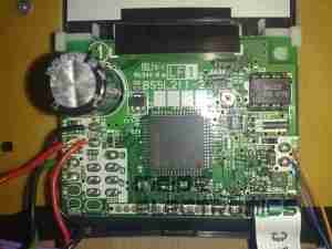
PCB under the top cover with the main CPU, a MN101C77CBM from Panasonic. This CPU features 48K Mask ROM & 3K of RAM. Max clock frequency is 20MHz. 32kHz clock crystal visible underneath a Rohm BA6220 Electronic speed controller IC.
This is used to drive the printer motor at a constant accurate speed, to feed the tape past the thermal head. Miniature potentiometer adjusts speed.
Ribbon cable at the bottom of the board connects to the print head, various wiring at the left connects to the battery & DC Jack.

Printer Drive
Printer Drive

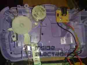
Printer drive mechanism. Small DC motor drives the pinch roller though a gear train. DC Jack & reverse polarity protection diode is on the right.
This unit uses a centre negative DC jack, which is unusual.

Cartridge
Cartridge

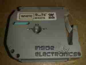
Thermal tape cartridge, black text on white background.

Posted on Leave a comment

Belkin 2 Port KVM Switch

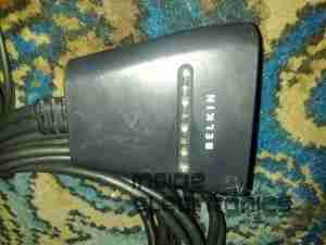
Main Body
Main Body

Here is an old type KVM switch, PS/2 & VGA interface.

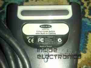
Label
Label

Details Label

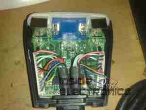
Top Removed
Top Removed

Top removed from the main body, the cables coming in from the bottom connect to the VGA, keyboard & mouse ports on the slave computers, the connectors at the top connect to the single monitor, keyboard & mouse.

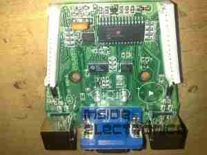
PCB
PCB

PCB removed from the body. This is driven by a PIC16C57C-04 microcontroller.
The pair of LEDs indicate which computer is using the peripherals at any one time.

Posted on Leave a comment

USB Multi Card Reader

Card Reader
Card Reader

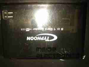
Here is a cheap USB 8-in-1 card reader. Power & Access LEDs are on top left.

PCB Top
PCB Top

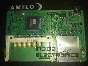
Top of the PCB. The OTi IC is the interface IC to the USB port, part number is OTI002126. Card sockets on the top here are CF/Microdrive & Memory Stick.

PCB Bottom
PCB Bottom

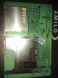
Bottom of the PCB with the SD/MMC, Smart Media

Posted on Leave a comment

Cheap Ball Mouse

Mouse
Mouse

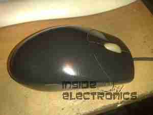
Cheap old style ball mouse. PS/2 interface.

Top Removed
Top Removed

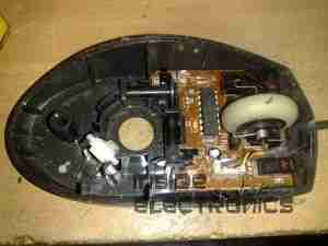
Top removed from the mouse, the ball fits in the gap in the centre. The slotted discs are visible which contact the ball & move relative to the surface the mouse is on.

PCB
PCB

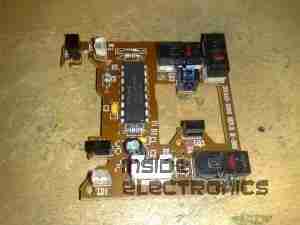
PCB removed from the shell. Pairs of IR LEDs & Phototransistors make rotary encoders with the slotted discs. The microswitches read the mouse buttons & wheel.
IC in the centre interfaces with the PC over a PS/2 connection.

Posted on Leave a comment

Vivicam 5190

Front
Front

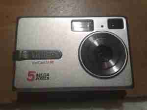
A 5 megapixel digital camera from Vivitar. Visible here is the lens, viewfinder & flash.

Back
Back

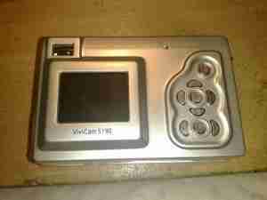
Rear of the unit showing the LCD & user control buttons.

Cover Removed
Cover Removed

Front frame removed showing some of the internals. Shutter assembly & lens in centre, battery compartment at left.

Rear Cover Removed
Rear Cover Removed

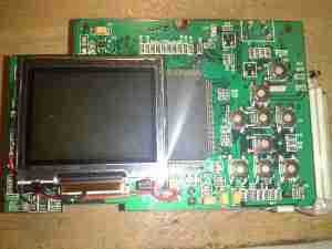
Rear frame removede, showing the LCD module & tactile switches.

LCD
LCD

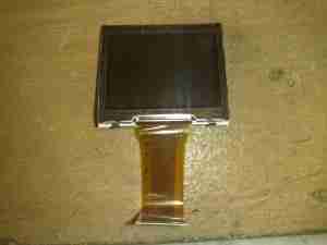
LCD module removed from the PCB

Flash PCB
Flash PCB

Flash PCB removed. Transformer is fed with the 4.5v from the 3 AA cells & steps it up to ~300v DC for the flash capacitor. A pulse transformer energizes an electrode next to the Xenon flash tube with ~5kV to ionize the gas.

Main PCB
Main PCB

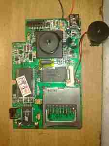
Main PCB removed. Internal flash ROM & RAM IC visible above the SD card socket. USB connector is at the top right, next to the piezo buzzer.

CPU
CPU

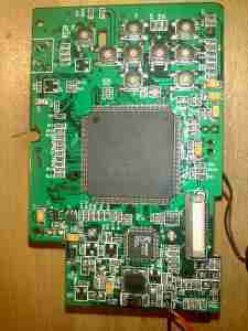
Main processor on reverse side of the PCB.

Image Sensor
Image Sensor

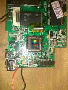
Closeup of the CMOS image sensor with the lens assembly removed.

Posted on Leave a comment

USB-IDE/SATA Adaptor

Front
Front

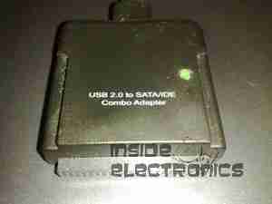
This is a device to use an IDE or SATA interface drive via a USB connection. Here is the front of the device, IDE interface at the bottom, 2.5″ form factor.

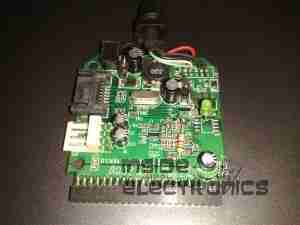
PCB Top
PCB Top

PCB removed from the casing. USB cable exits the top, 12v DC power jack to the left.
SATA interface below the DC Jack.
Molex connector below SATA is the power output for the drive in use. This unit has a built in 5v regulator.

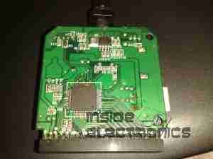
PCB Bottom
PCB Bottom

Bottom of the PCB showing the interface IC.

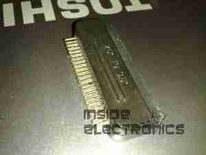
Drive Adaptor
Drive Adaptor

Adaptor to plug into the 44-pin 2.5″ form factor IDE interface on the adaptor, converts to standard 40-pin 3.5″ IDE.

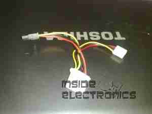
Power Cable
Power Cable

Power pigtail with standard Molex & SATA power plugs.