The old Panasonic NV-M5 has the standard for the time CRT based viewfinder assembly, which will happily take a composite video signal from an external source.
This viewfinder has many more connections than I would have expected, as it has an input for the iris signal, which places a movable marker on the edge of the display. This unit also has a pair of outputs for the vertical & horizontal deflection signals, I imagine for sync, but I’ve never seen these signals as an output on a viewfinder before.
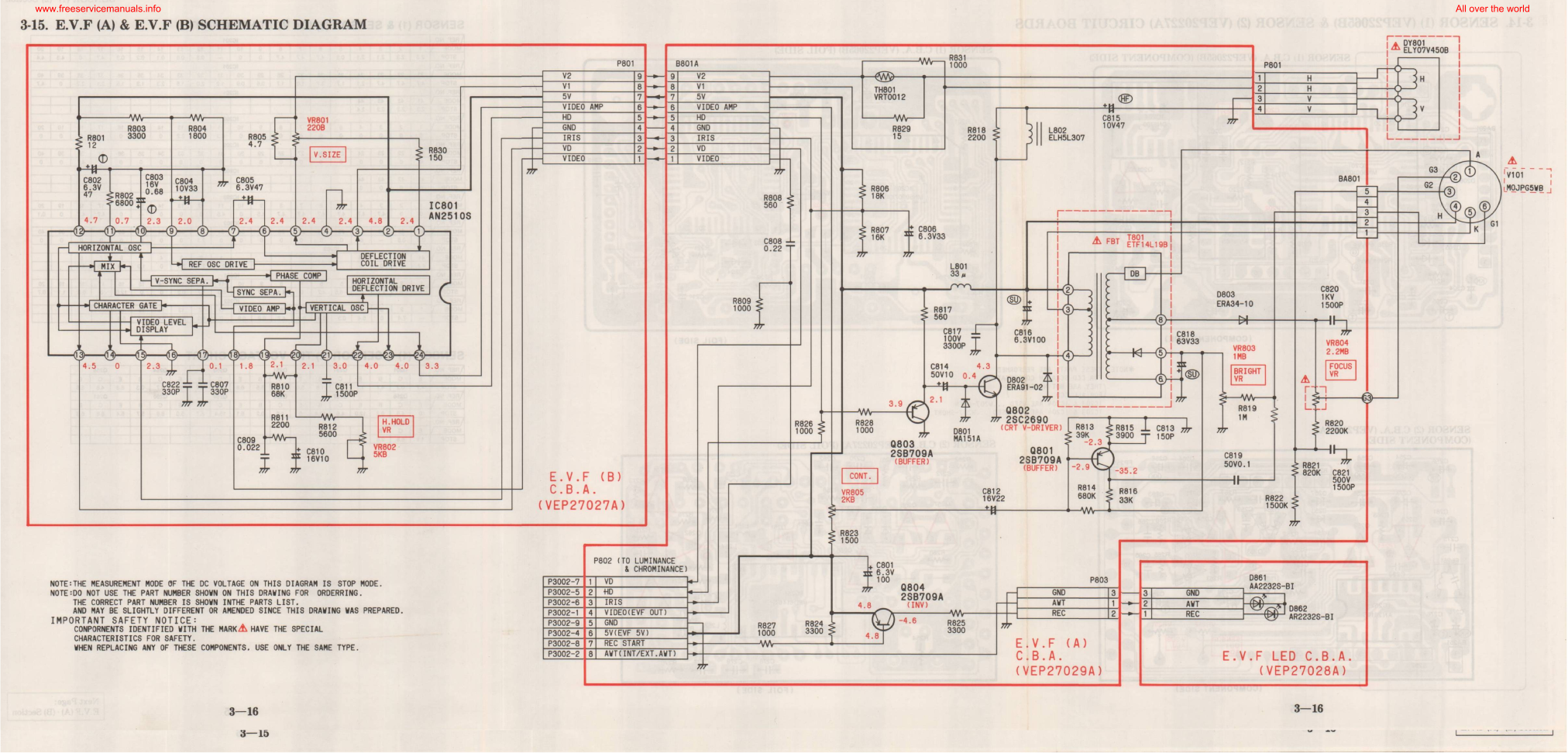
EVF Schematic
Luckily I managed to get a service manual for the camera with a full schematic.
This unit takes a 5v input, as opposed to the 8-12v inputs on previous cameras, so watch out for this! There’s also no reverse polarity protection either.
Pins
Making the iris marker vanish from the screen is easy, just put a solder bridge between pins 15 & 16 of the drive IC. The important pins on the interface connector are as follows:
Pin 3: GND
Pin 4: Video Input
Pin 5: Video GND
Pins 6: +5v Supply
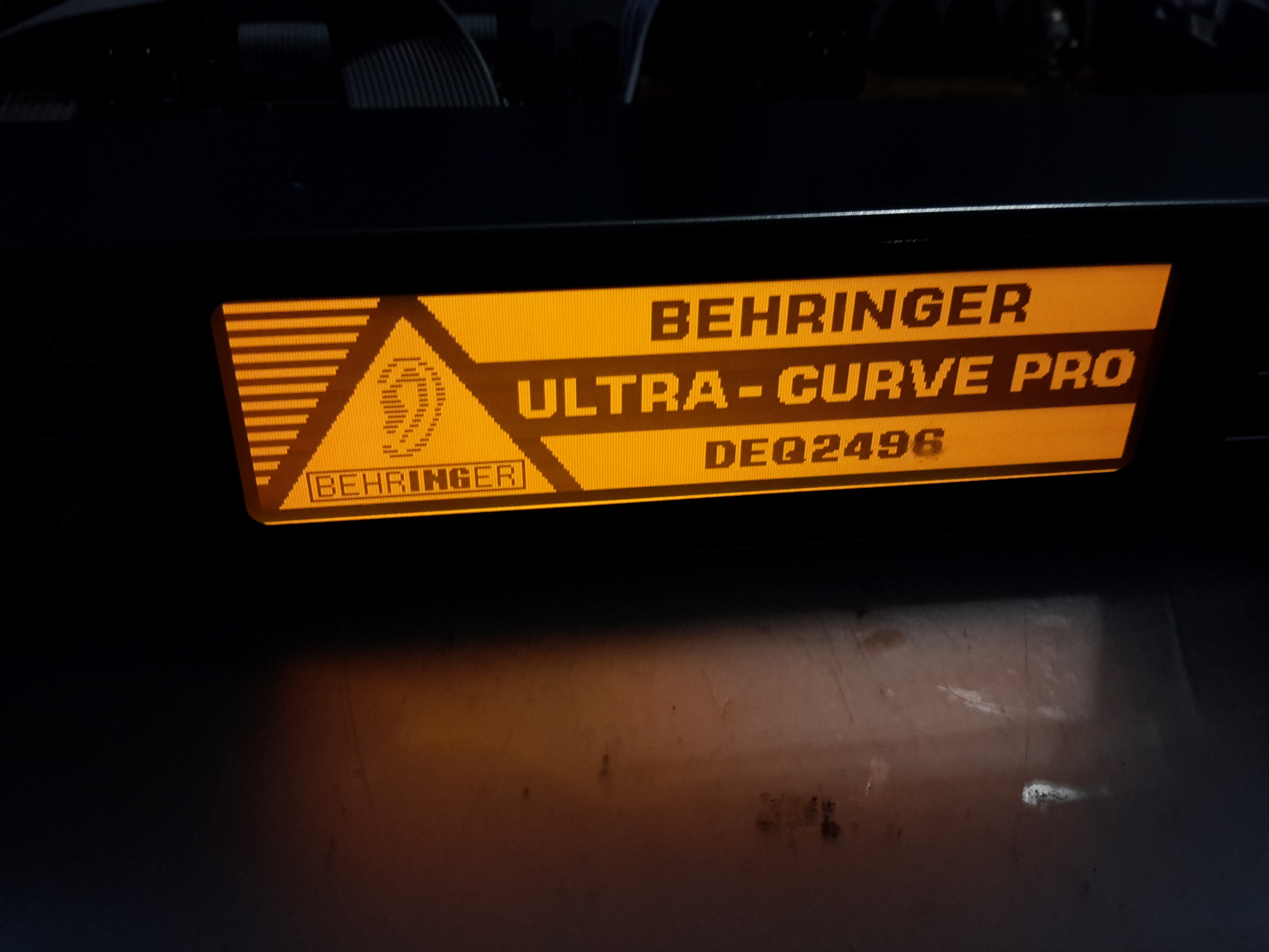
I was recently given this unit, along with another Behringer sound processor to repair, as the units were both displaying booting problems. This first one is a rather swish Mastering Processor, which has many features I’ll leave to Behringer to explain 😉
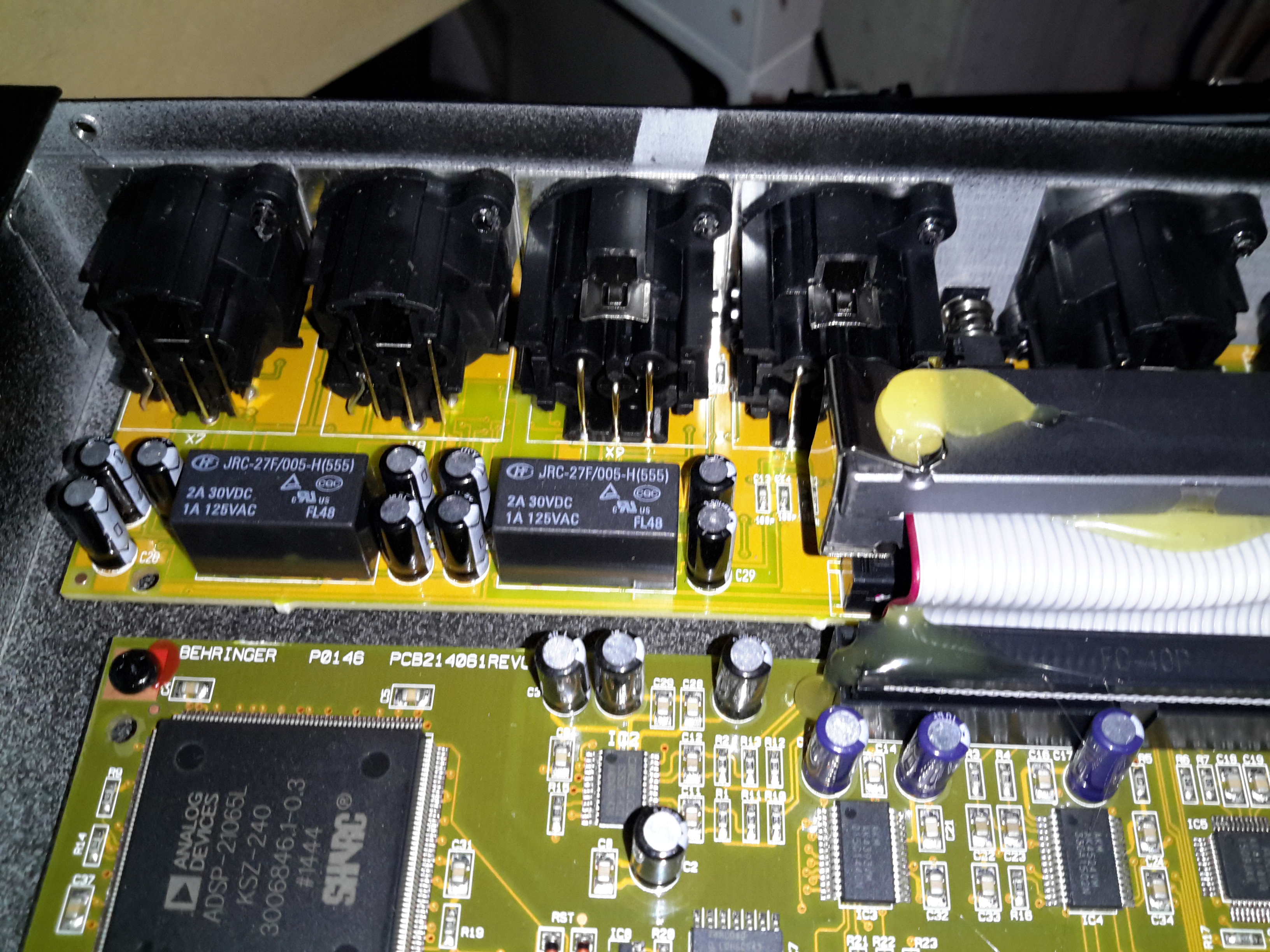
Input Board & Relays
All the inputs are on the back of this 19″ rackmount bit of kit, nothing much on this PCB other than the connectors & a couple of switching relays.
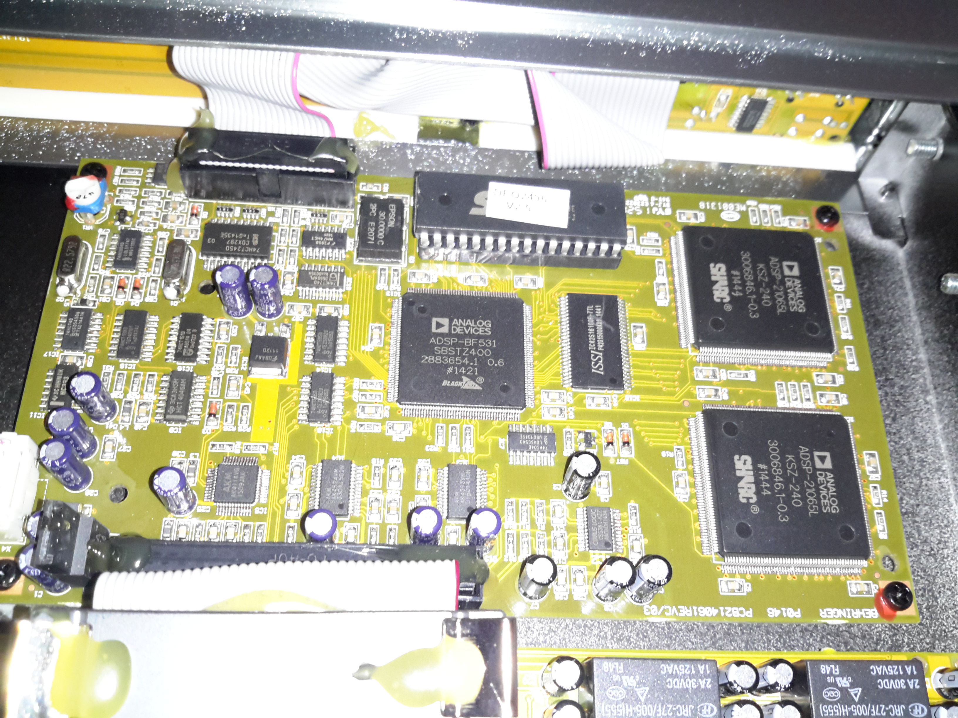
Main Processor PCB
All the magic is done on the main processor PCB, which is host to 3 Analog Devices DSP processors:
ADSP-BF531 BlackFin DSP. This one is probably handling most of the audio processing, as it’s the most powerful DSP onboard at 600Mhz. There’s a ROM on board above this for the firmware & a single RAM chip. On the right are a pair of ADSP-21065 DSP processors at a lower clock rate of 66MHz. To the left is some glue logic to interface the user controls & dot-matrix LCD.
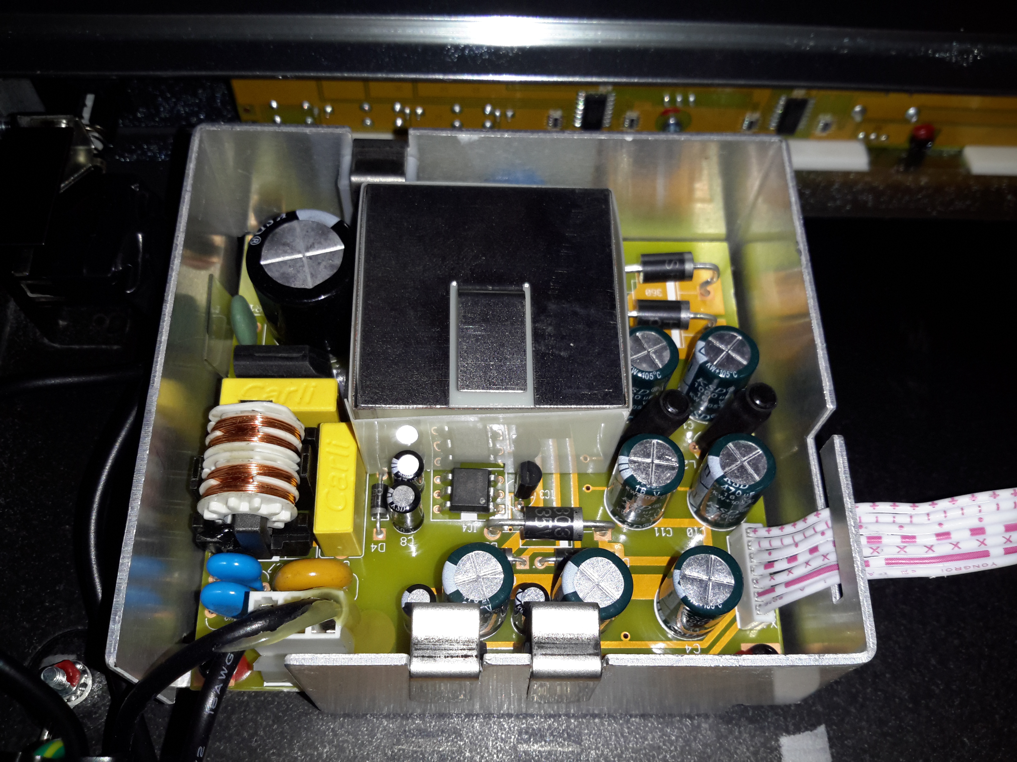
PSU Module
The PSU in this unit is a pretty standard looking SMPS, with some extra noise filtering & shielding. The main transformer is underneath the mu-metal shield in the centre of the board.
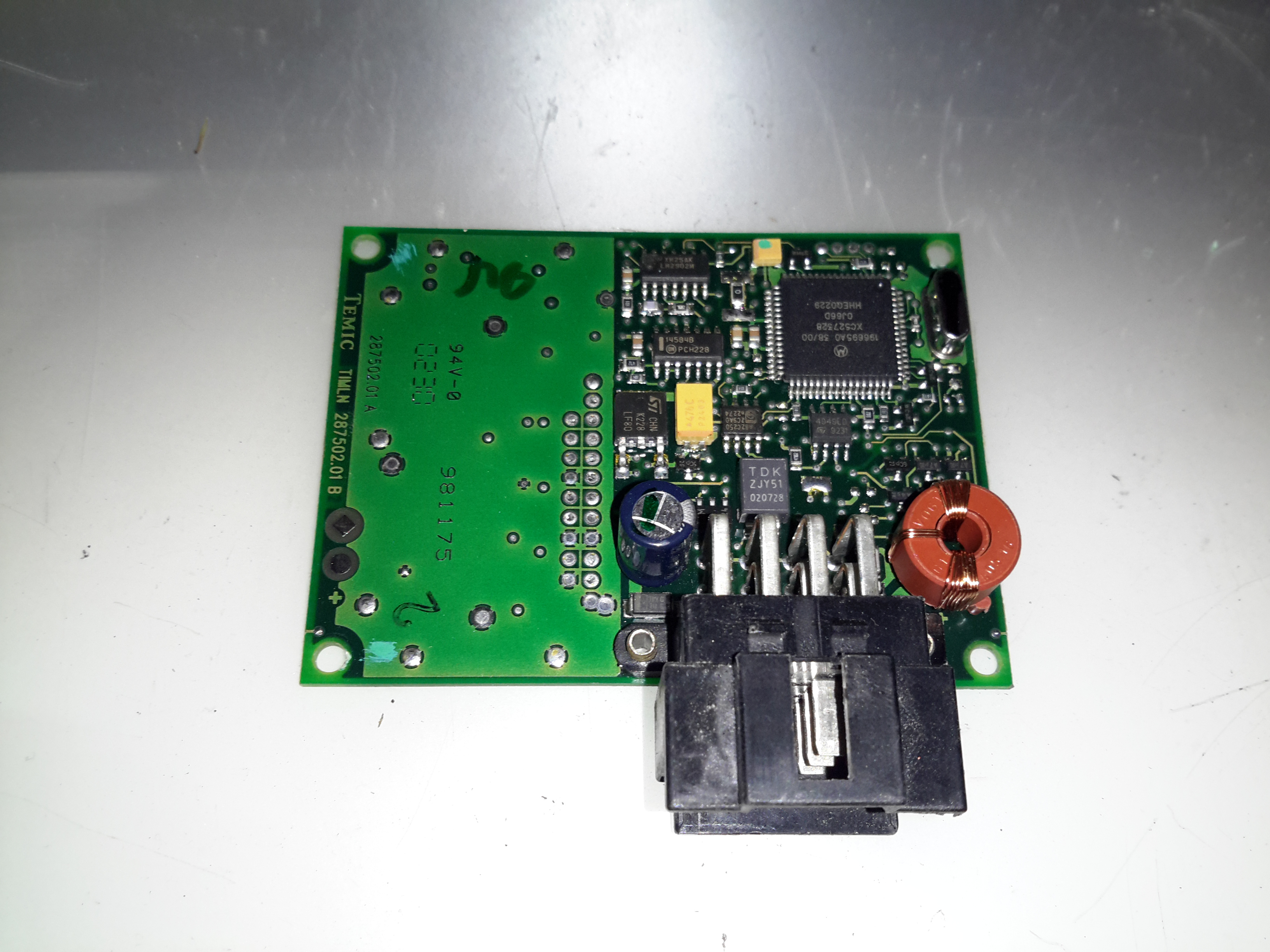
The other day I was given a random pile of car electronic parts from the scrap bin at the local garage, so I decided to do a few teardowns. This first one is a Temic Central Locking / Immobiliser module from a Mercedes van. Judging by the 125kHz stamped on the label, this also has RFID capability.
PCB
The casing just unclips, revealing the PCB. Surprisingly for an automotive module, there is no conformal coating on this (they’re usually heavily coated in protective lacquer to prevent moisture ingress).
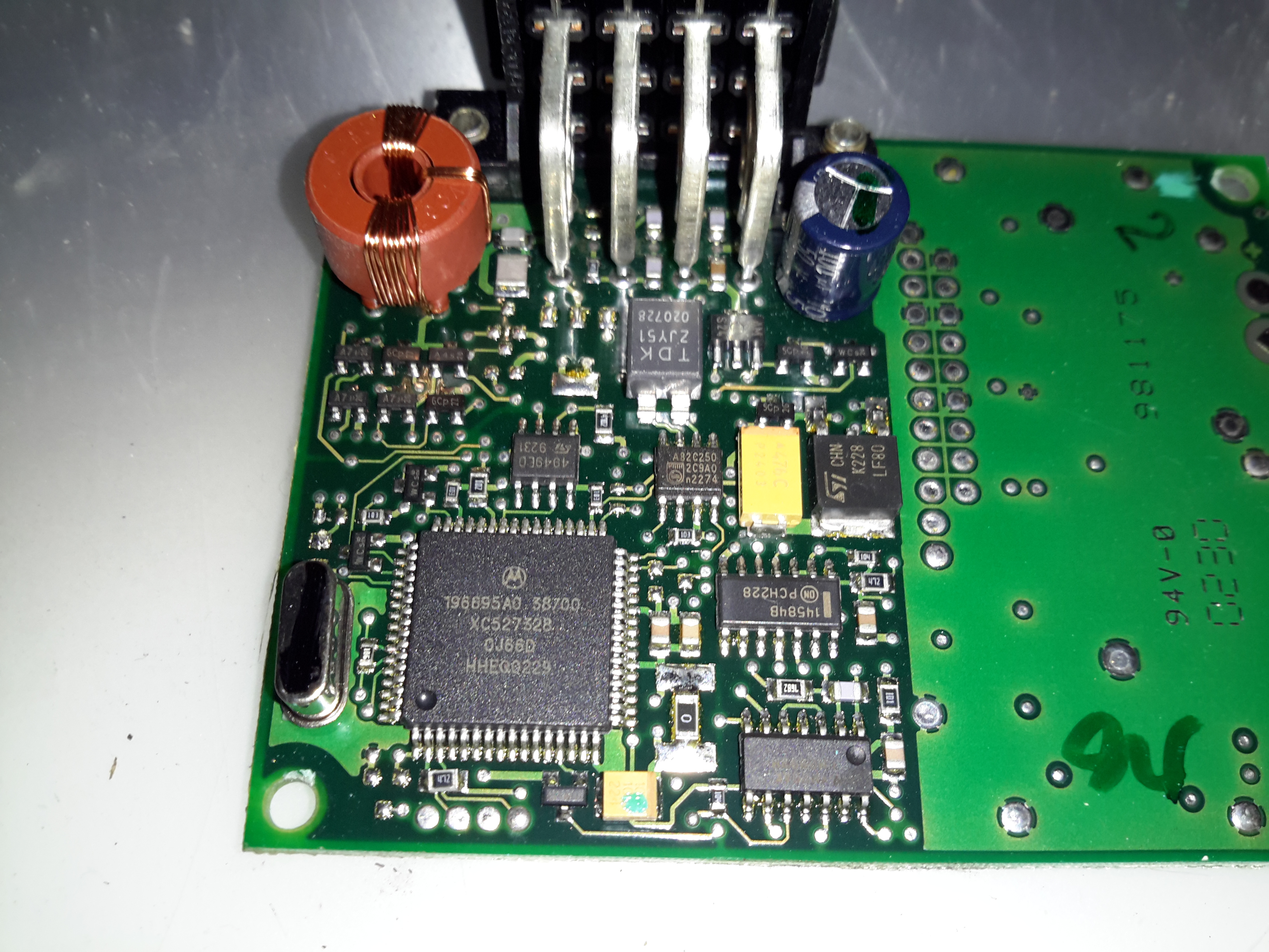
Microcontroller
The large IC from Motorola I’m assuming to be a microcontroller, but I didn’t manage to find anything from the markings. There’s not much else in here apart from some glue logic, and what I think is the 125Khz toroidal antenna in the top left corner.
My new DMM I posted about a while back came with PC software & drivers for the RS-232 interface, on a CD. I haven’t used CDs for some time, so I had to dig out my USB drive.
The Tenma website doesn’t list the software for all their models, so to help others I’m posting an archive of all the supplied drivers here. The archive contains software & drivers for the following Tenma models:
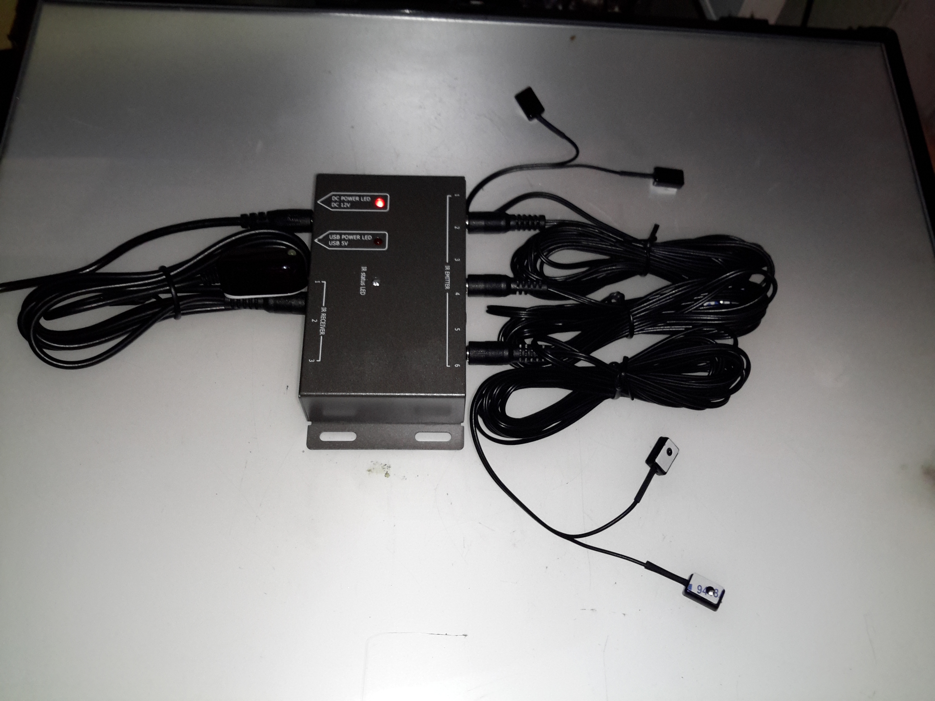
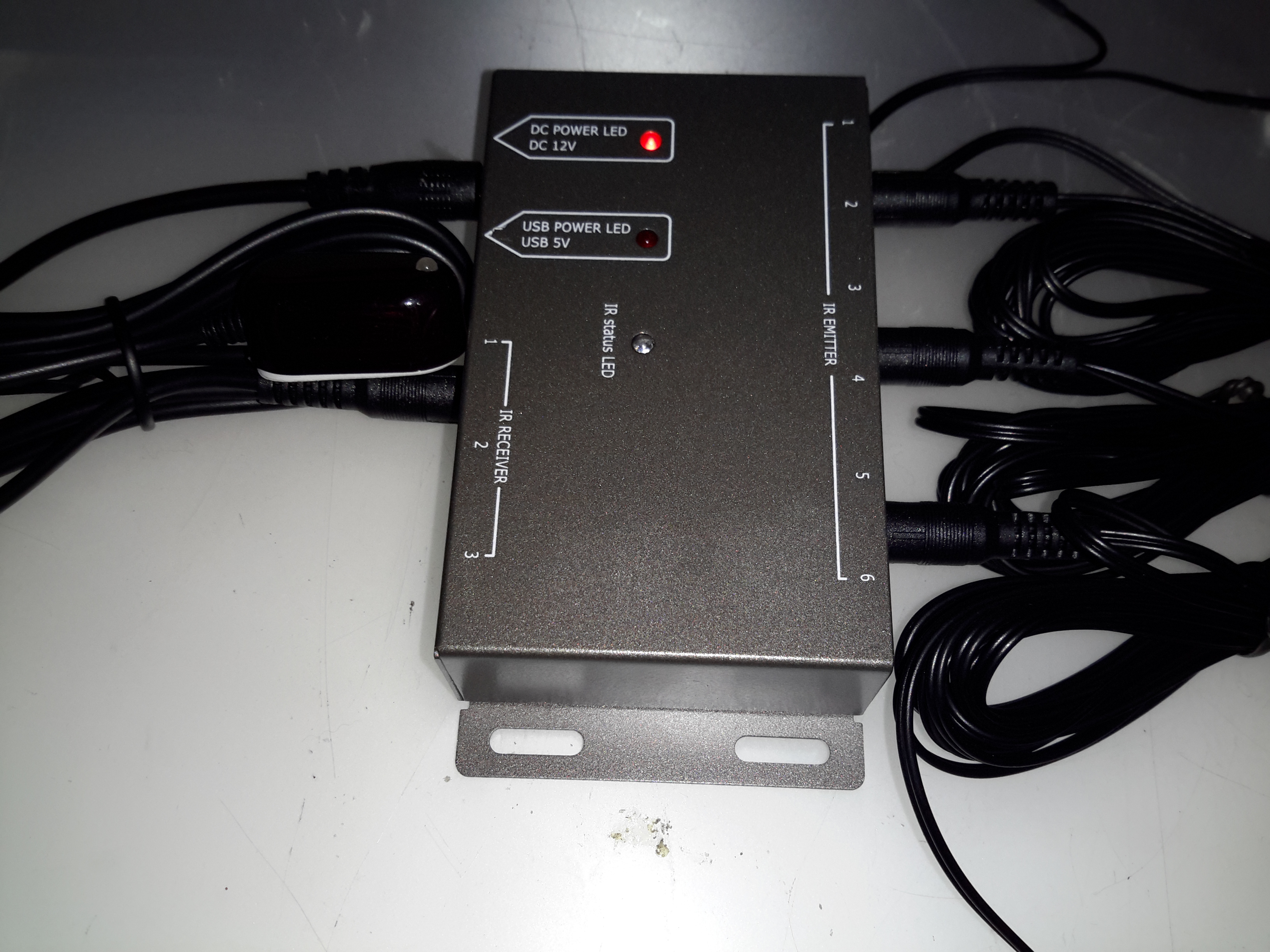
Here’s another random gadget for teardown, this time an IR remote control repeater module. These would be used where you need to operate a DVD player, set top box, etc in another room from the TV that you happen to be watching. An IR receiver sends it’s signal down to the repeater box, which then drives IR LEDs to repeat the signal.
Repeater Module
Not much to day about the exterior of this module, the IR input is on the left, up to 3 receivers can be connected. The outputs are on the right, up to 6 repeater LEDs can be plugged in. Connections are done through standard 3.5mm jacks.
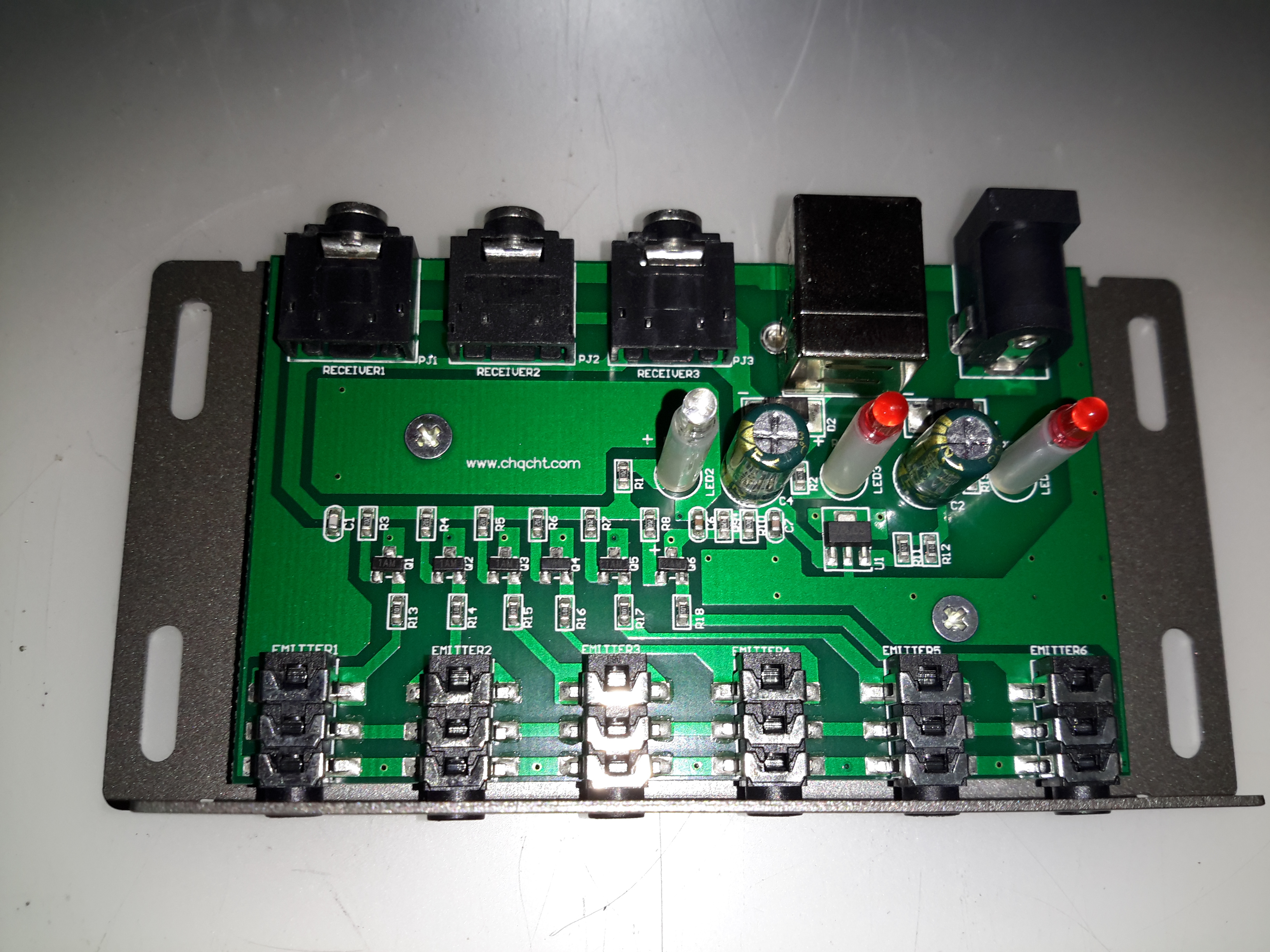
Repeater PCB
Not much inside this one at all, there are 6 transistors which each drive an LED output. This “dumb” configuration keeps things very simple, no signal processing has to be done. Power is either provided by a 12v input, which is fed into a 7805 linear regulator, or direct from USB.
For some time now I’ve been running a large disk array to store all the essential data for my network. The current setup has 10x 4TB disks in a RAID6 array under Linux MD.
Up until now the disks have been running in external Orico 9558U3 USB3 drive bays, through a PCIe x1 USB3 controller. However in this configuration there have been a few issues:
Congestion over the USB3 link. RAID rebuild speeds were severely limited to ~20MB/s in the event of a failure. General data transfer was equally as slow.
Drive dock general reliability. The drive bays are running a USB3 – SATA controller with a port expander, a single drive failure would cause the controller to reset all disks on it’s bus. Instead of losing a single disk in the array, 5 would disappear at the same time.
Cooling. The factory fitted fans in these bays are total crap – and very difficult to get at to change. A fan failure quickly allows the disks to heat up to temperatures that would cause failure.
Upgrade options difficult. These bays are pretty expensive for what they are, and adding more disks to the USB3 bus would likely strangle the bandwidth even further.
Disk failure difficult to locate. The USB3 interface doesn’t pass on the disk serial number to the host OS, so working out which disk has actually failed is difficult.
To remedy these issues, a proper SATA controller solution was required. Proper hardware RAID controllers are incredibly expensive, so they’re out of the question, and since I’m already using Linux MD RAID, I didn’t need a hardware controller anyway.
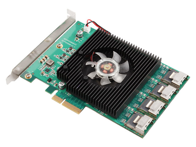
16-Port HBA
A quick search for suitable HBA cards showed me the IOCrest 16-port SATAIII controller, which is pretty low cost at £140. This card breaks out the SATA ports into standard SFF-8086 connectors, with 4 ports on each. Importantly the cables to convert from these server-grade connectors to standard SATA are supplied, as they’re pretty expensive on their own (£25 each).
This card gives me the option to expand the array to 16 disks eventually, although the active array will probably be kept at 14 disks with 2 hot spares, this will give a total capacity of 48TB.
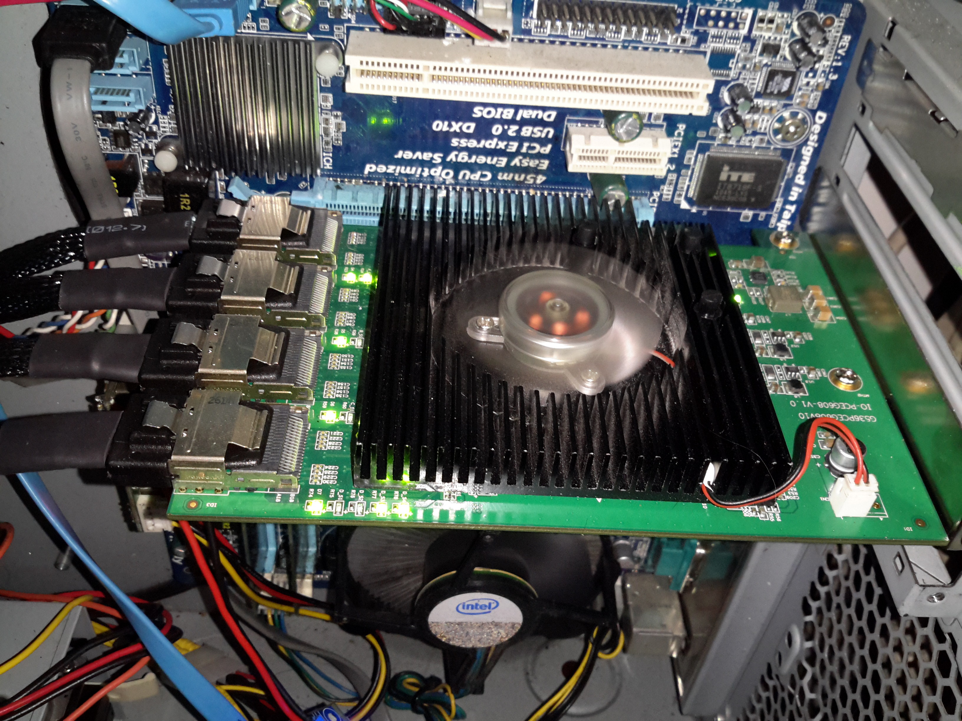
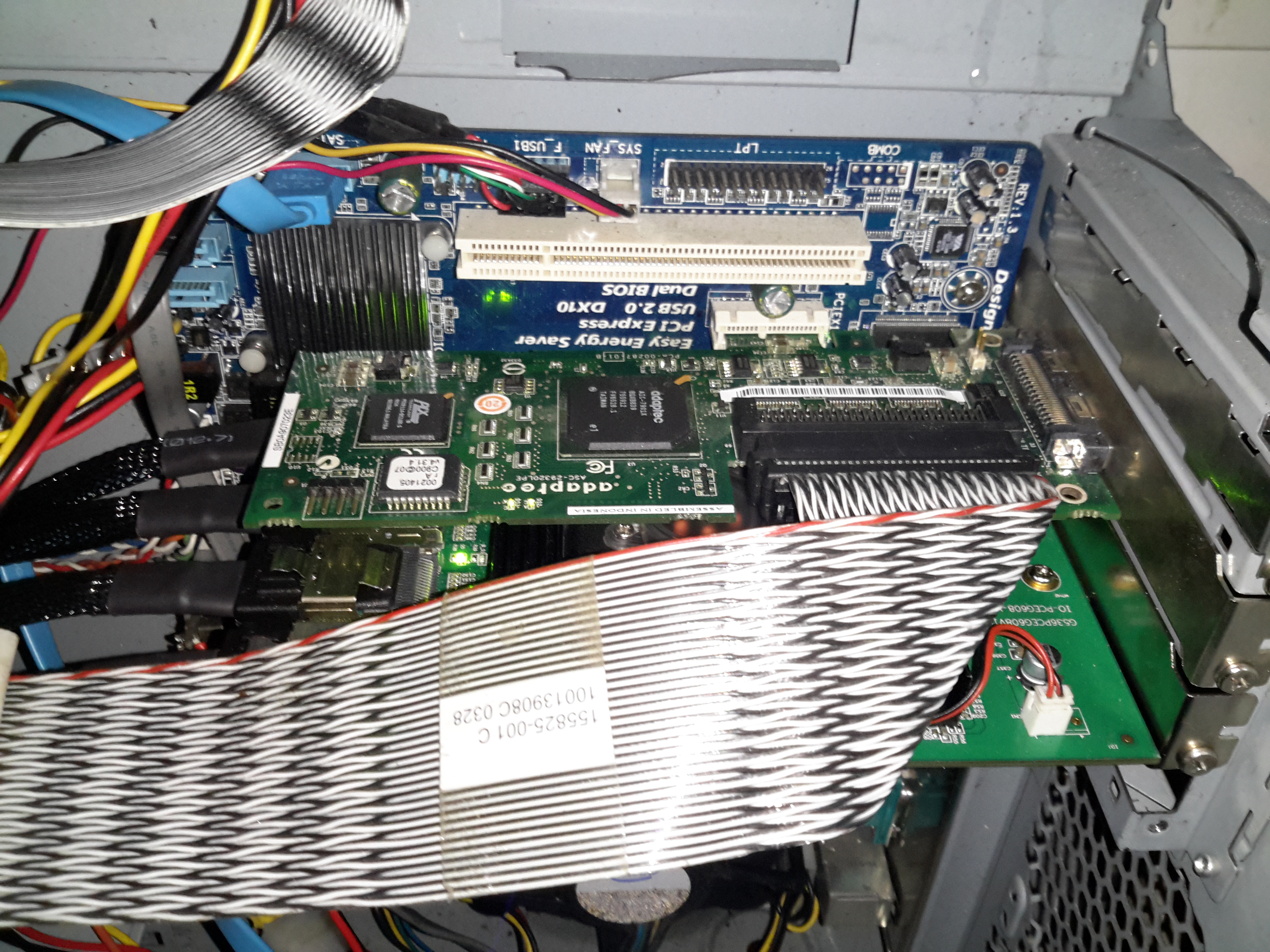
SATA HBA
Here’s the card installed in the host machine, with the array running. One thing I didn’t expect was the card to be crusted with activity LEDs. There appears to be one LED for each pair of disks, plus a couple others which I would expect are activity on the backhaul link to PCIe. (I can’t be certain, as there isn’t any proper documentation anywhere for this card. It certainly didn’t come with any ;)).
I’m not too impressed with the fan that’s on the card – it’s a crap sleeve bearing type, so I’ll be keeping a close eye on this for failure & will replace with a high quality ball-bearing fan when it finally croaks. The heatsink is definitely oversized for the job, with nothing installed above the card barely gets warm, which is definitely a good thing for life expectancy.
Update 10/02/17 – The stock fan is now dead as a doornail after only 4 months of continuous operation. Replaced with a high quality ball-bearing 80mm Delta fan to keep things running cool. As there is no speed sense line on the stock fan, the only way to tell it was failing was by the horrendous screeching noise of the failing bearings.
SCSI Controller
Above is the final HBA installed in the PCIe x1 slot above – a parallel SCSI U320 card that handles the tape backup drives. This card is very close to the cooling fan of the SATA card, and does make it run warmer, but not excessively warm. Unfortunately the card is too long for the other PCIe socket – it fouls on the DIMM slots.
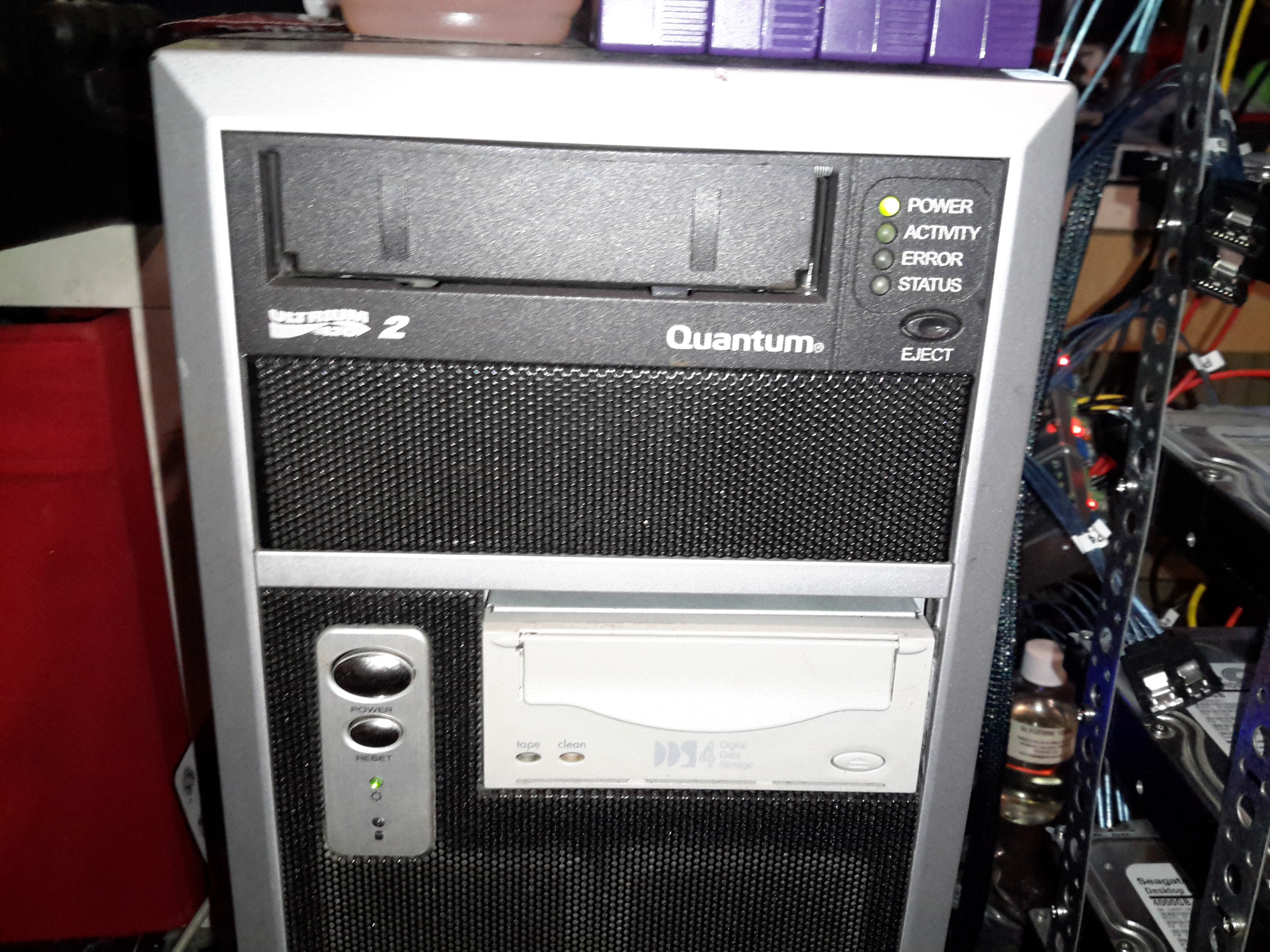
Backup Drives
The tape drives are LTO2 300/600GB for large file backup & DDS4 20/40GB DAT for smaller stuff. These were had cheap on eBay, with a load of tapes. Newer LTO drives aren’t an option due to cost.
The main disk array is currently built as 9 disks in service with a single hot spare, in case of disk failure, this gives a total size after parity of 28TB:
/dev/md0:
        Version : 1.2
  Creation Time : Wed Mar 11 16:01:01 2015
     Raid Level : raid6
     Array Size : 27348211520 (26081.29 GiB 28004.57 GB)
  Used Dev Size : 3906887360 (3725.90 GiB 4000.65 GB)
   Raid Devices : 9
  Total Devices : 10
    Persistence : Superblock is persistent

  Intent Bitmap : Internal

    Update Time : Mon Nov 14 14:28:59 2016
          State : active
 Active Devices : 9
Working Devices : 10
 Failed Devices : 0
  Spare Devices : 1

         Layout : left-symmetric
     Chunk Size : 64K

           Name : Main-PC:0
           UUID : 266632b8:2a8a3dd3:33ce0366:0b35fad9
         Events : 773938

    Number   Major   Minor   RaidDevice State
       0       8       48        0      active sync   /dev/sdd
       1       8       32        1      active sync   /dev/sdc
       9       8       96        2      active sync   /dev/sdg
      10       8      112        3      active sync   /dev/sdh
      11       8       16        4      active sync   /dev/sdb
       5       8      176        5      active sync   /dev/sdl
       6       8      144        6      active sync   /dev/sdj
       7       8      160        7      active sync   /dev/sdk
       8       8      128        8      active sync   /dev/sdi

      12       8        0        -      spare   /dev/sda
The disks used are Seagate ST4000DM000 Desktop HDDs, which at this point have ~15K hours on them, and show no signs of impending failure.
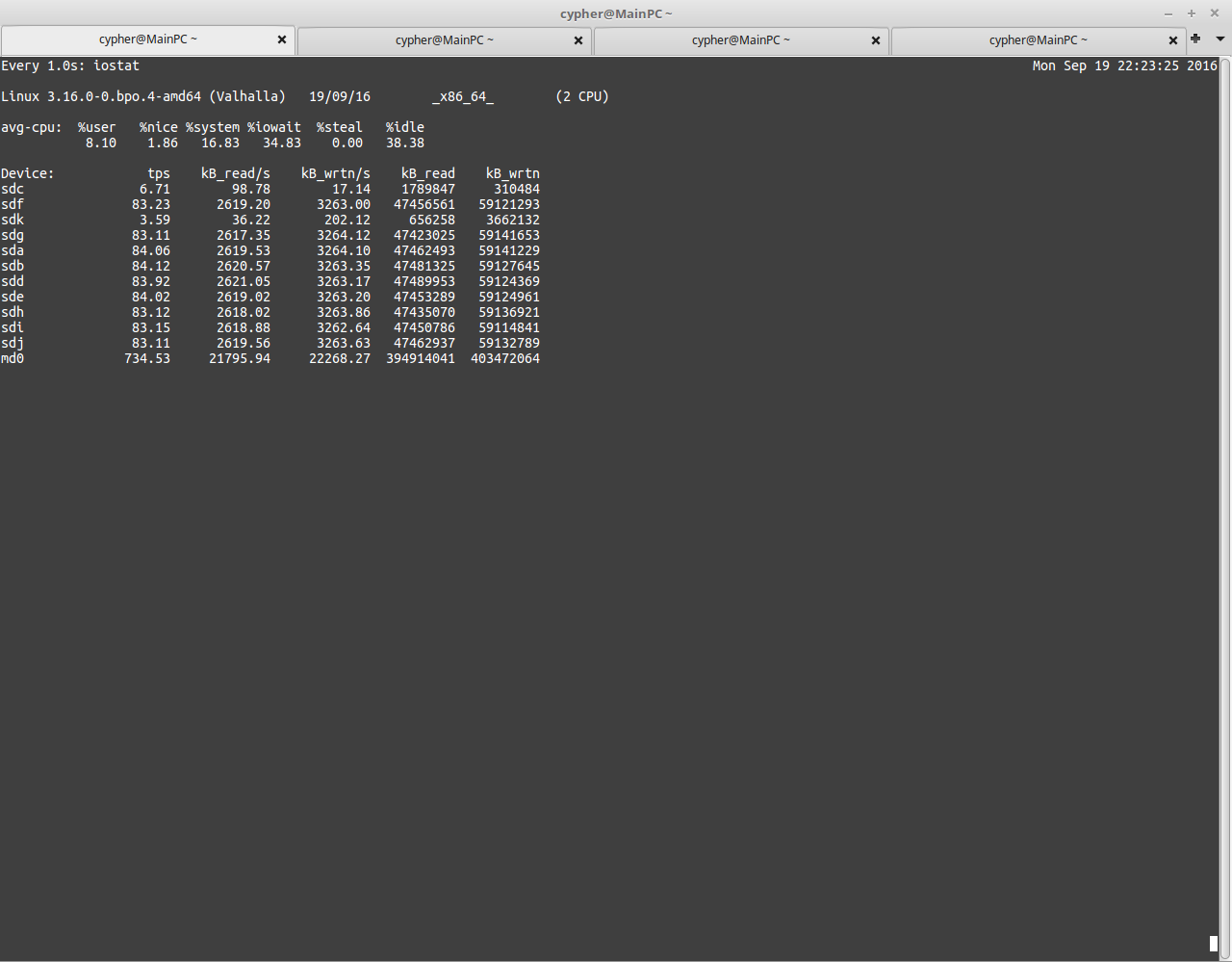
USB3 Speeds
Here’s a screenshot with the disk array fully loaded running over USB3. The aggregate speed on the md0 device is only 21795KB/s. Extremely slow indeed.
This card is structured similarly to the external USB3 bays – a PCI Express bridge glues 4 Marvell 9215 4-port SATA controllers into a single x8 card. Bus contention may become an issue with all 16 ports used, but as far with 9 active devices, the performance increase is impressive. Adding another disk to the active array would certainly give everything a workout, as rebuilding with an extra disk will hammer both read from the existing disks & will write to the new.
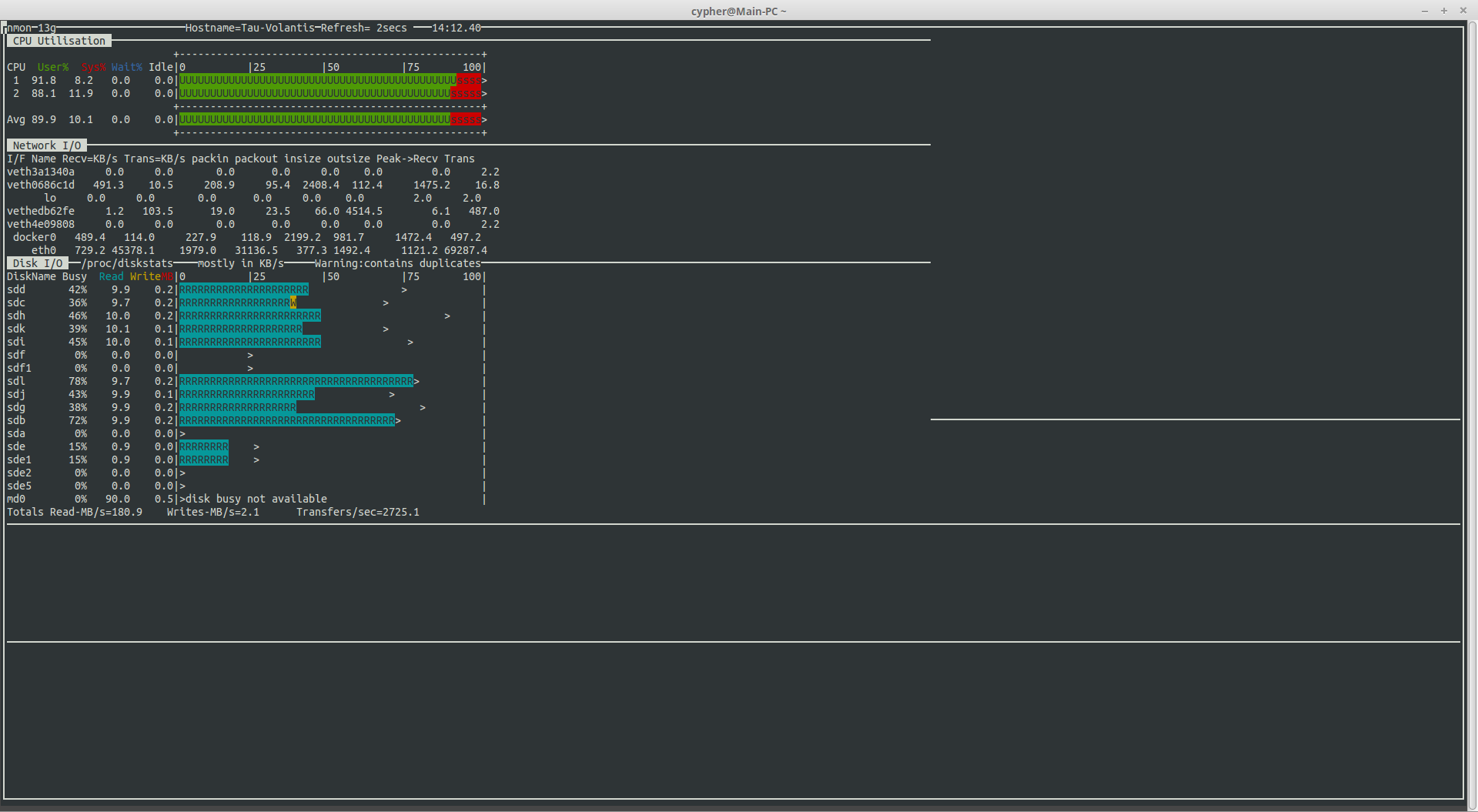
HBA Speeds
With all disks on the new controller, I’m sustaining read speeds of 180MB/s. (Pulling data off over the network). Write speeds are always going to be pretty pathetic with RAID6, as parity calculations have to be done. With Linux MD, this is done by the host CPU, which is currently a Core2Duo E7500 at 2.96GHz, with this setup, I get 40-60MB/s writes to the array with large files.
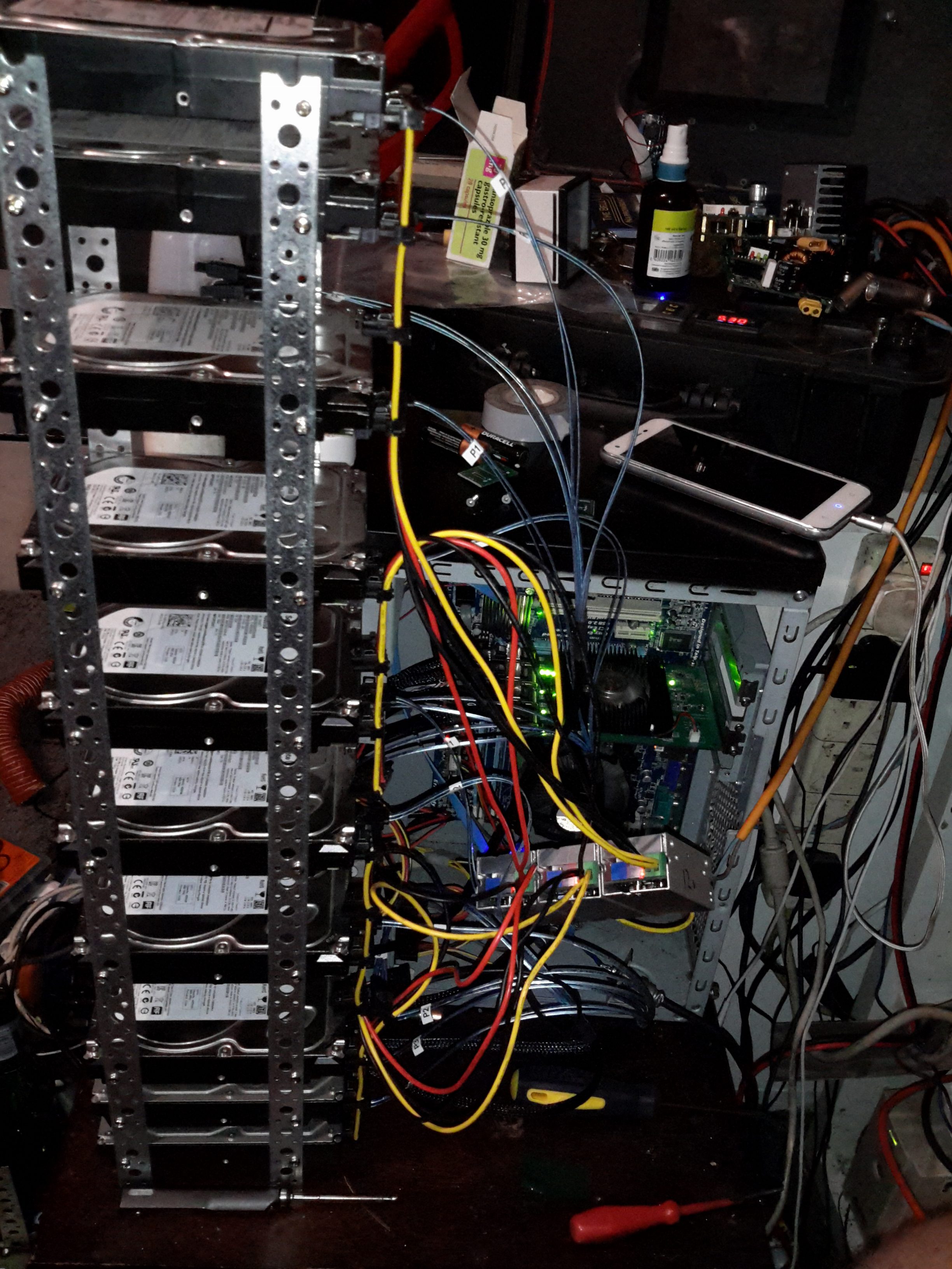
Disk Array
Since I don’t have a suitable case with built in drive bays, (again, they’re expensive), I’ve had to improvise with some steel strip to hold the disks in a stack. 3 DC-DC converters provides the regulated 12v & 5v for the disks from the main unregulated 12v system supply. Both the host system & the disks run from my central battery-backed 12v system, which acts like a large UPS for this.
The SATA power splitters were custom made, the connectors are Molex 67926-0001 IDC SATA power connectors, with 18AWG cable to provide the power to 4 disks in a string.
IDT Insertion Tool
These require the use of a special tool if you value your sanity, which is a bit on the expensive side at £25+VAT, but doing it without is very difficult. You get a very well made tool for the price though, the handle is anodised aluminium & the tool head itself is a 300 series stainless steel.
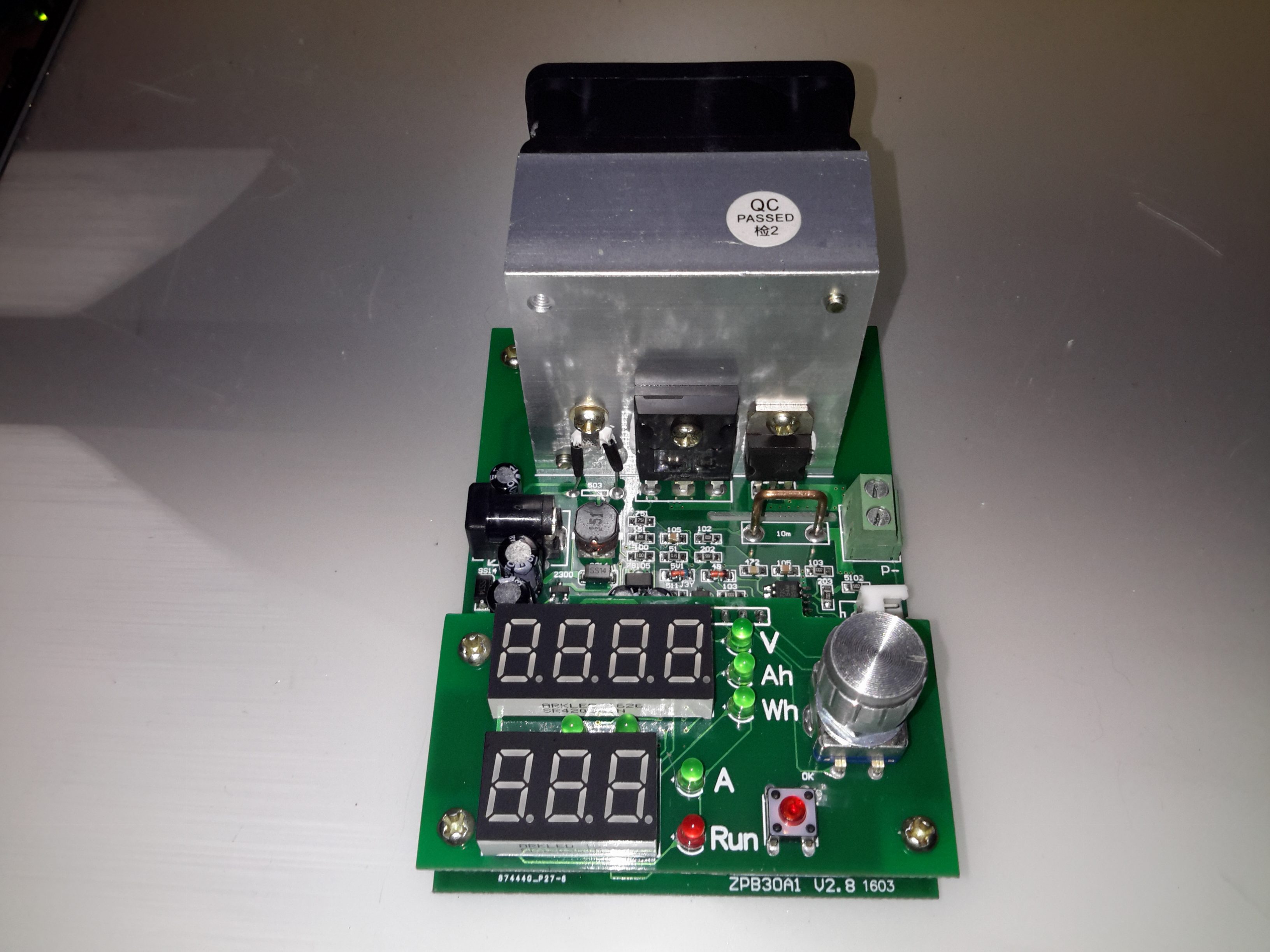
Here’s a useful tool for testing both power supplies & batteries, a dummy load. This unit is rated up to 60W, at voltages from 1v to 25v, current from 200mA to 9.99A.
This device requires a 12v DC power source separate from the load itself, to power the logic circuitry.
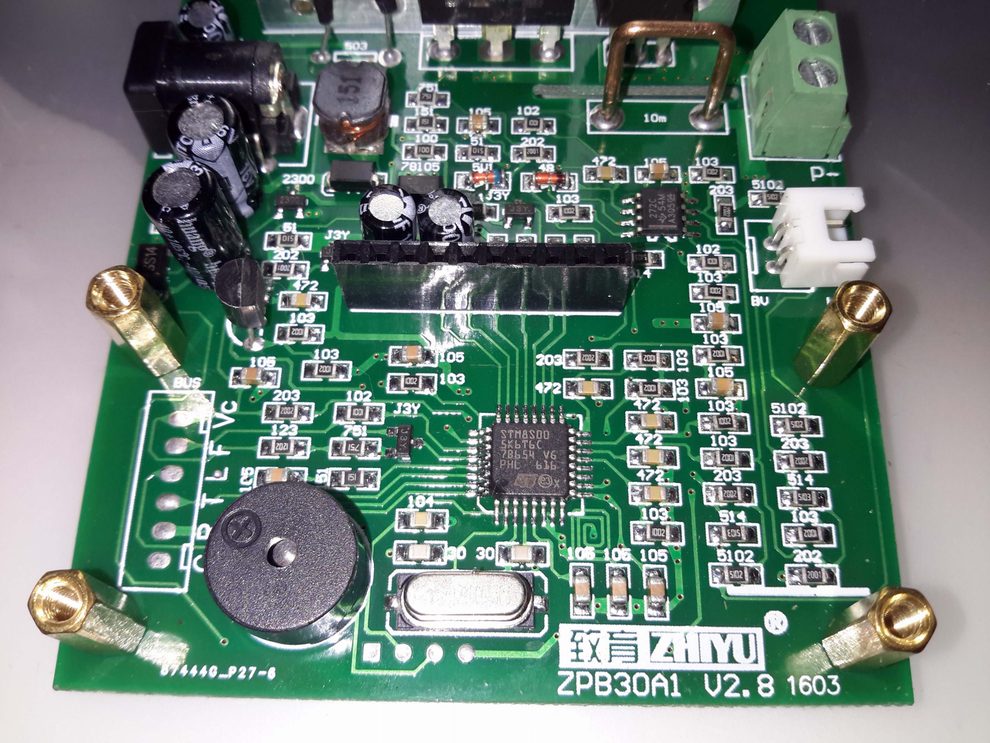
Microcontroller Section
Like many of these modules, the brains of the operation is an STM8 microcontroller. There’s a header to the left with some communication pins, the T pin transmits the voltage when the unit is operating, along with the status via RS232 115200 8N1. This serial signal is only present in DC load mode, the pin is pulled low in battery test mode. The 4 pins underneath the clock crystal are the programming pins for the STM8.
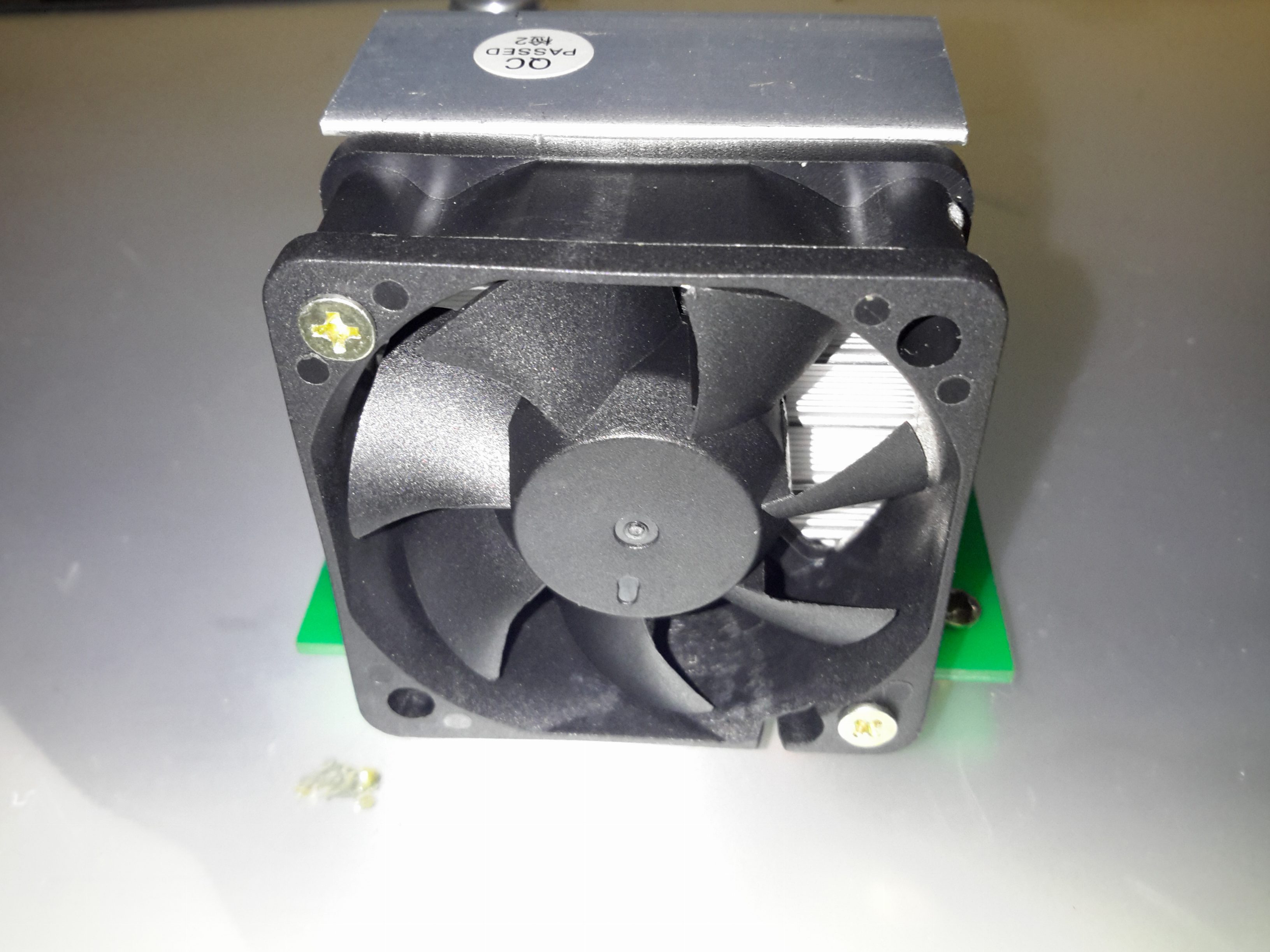
Serial CommsCooling Fan
The main heatsink is fan cooled, the speed is PWM controlled via the microcontroller depending on the temperature.
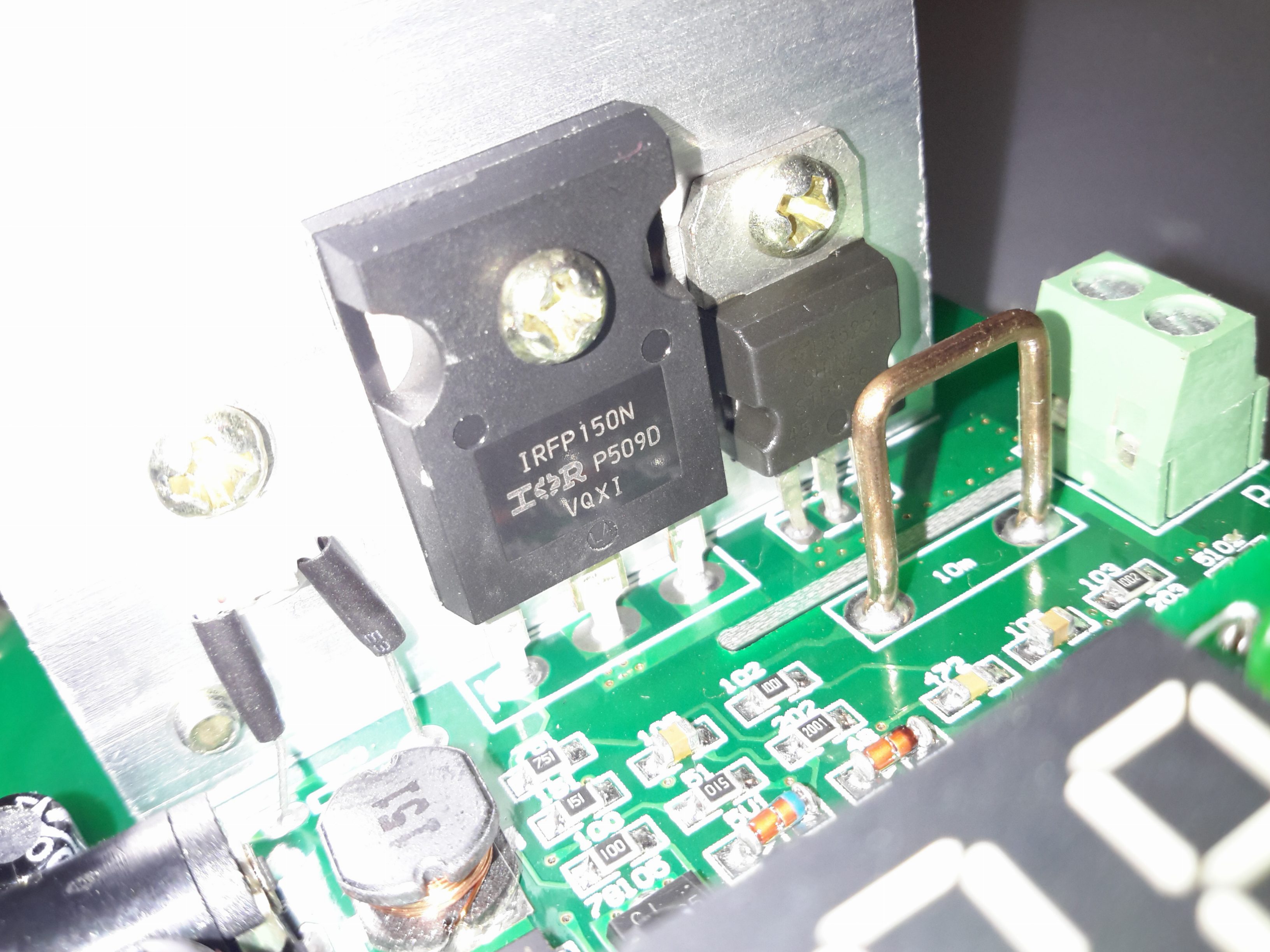
Main MOSFET
The main load MOSFET is an IRFP150N from Infineon. This device is rated at 100v 42A, with a max power dissipation of 160W. On the right is a dual diode for reverse polarity protection, this is in series with the MOSFET. On the left is the thermistor for controlling fan speed.
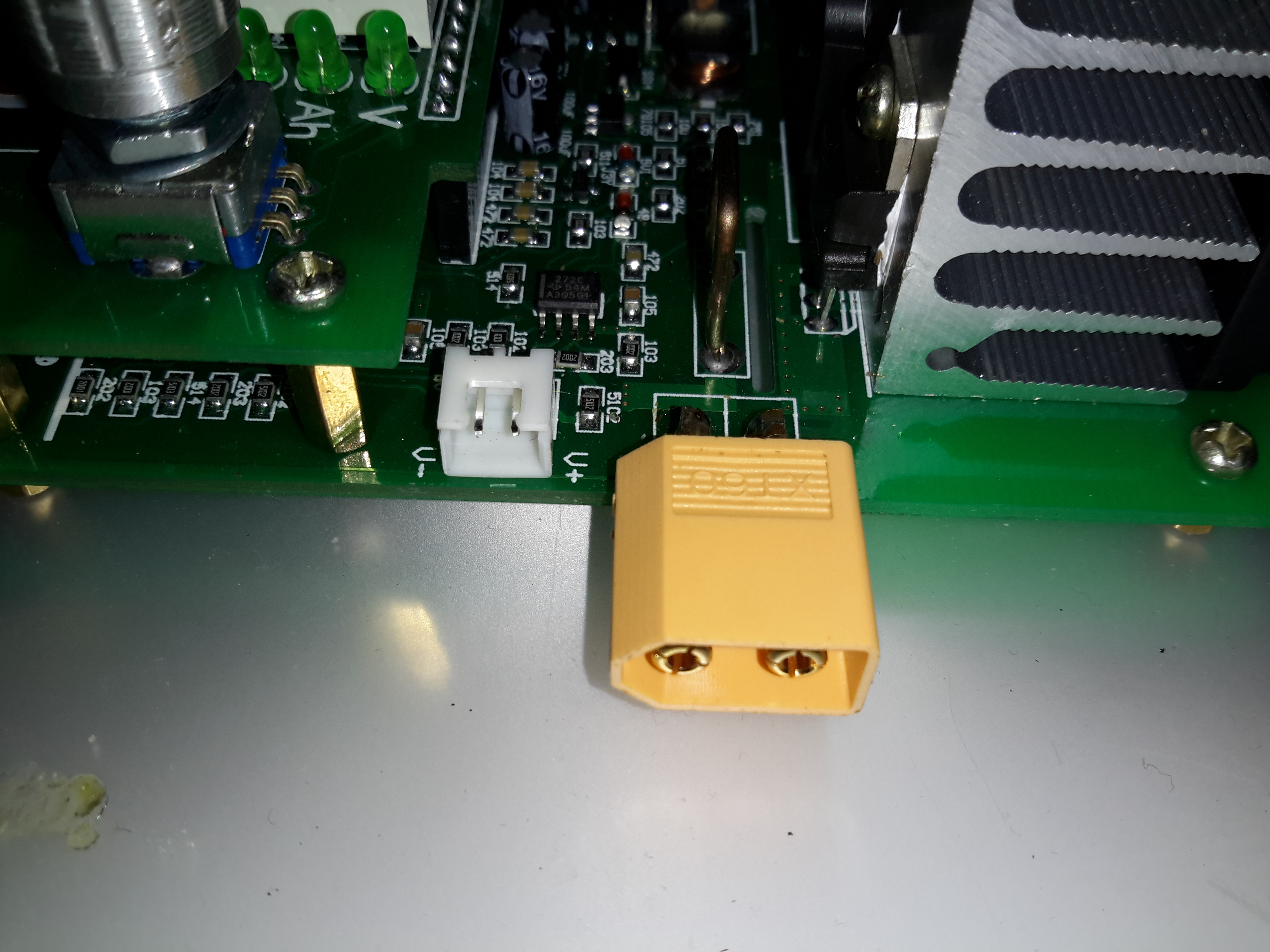
Load Terminals
The load is usually connected via a rising clamp terminal block. I’ve replaced it with a XT60 connector in this case as all my battery holders are fitted with these. This also removes the contact resistance of more connections for an adaptor cable. The small JST XH2 connector on the left is for remote voltage sensing. This is used for 4-wire measurements.
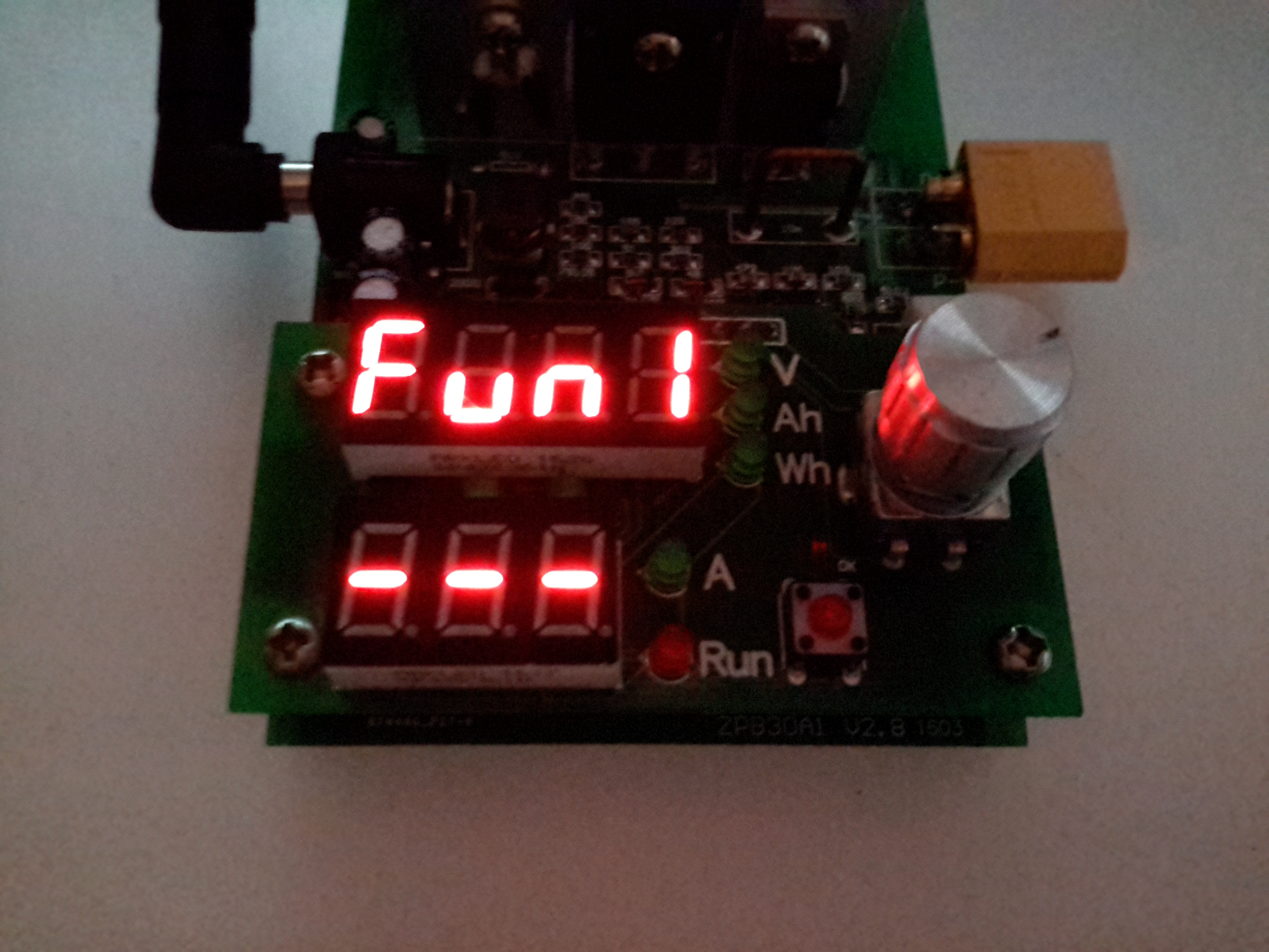
Function 1 – DC Load
Powering the device up while holding the RUN button gets you into the menu to select the operating modes. Function 1 is simple DC load.
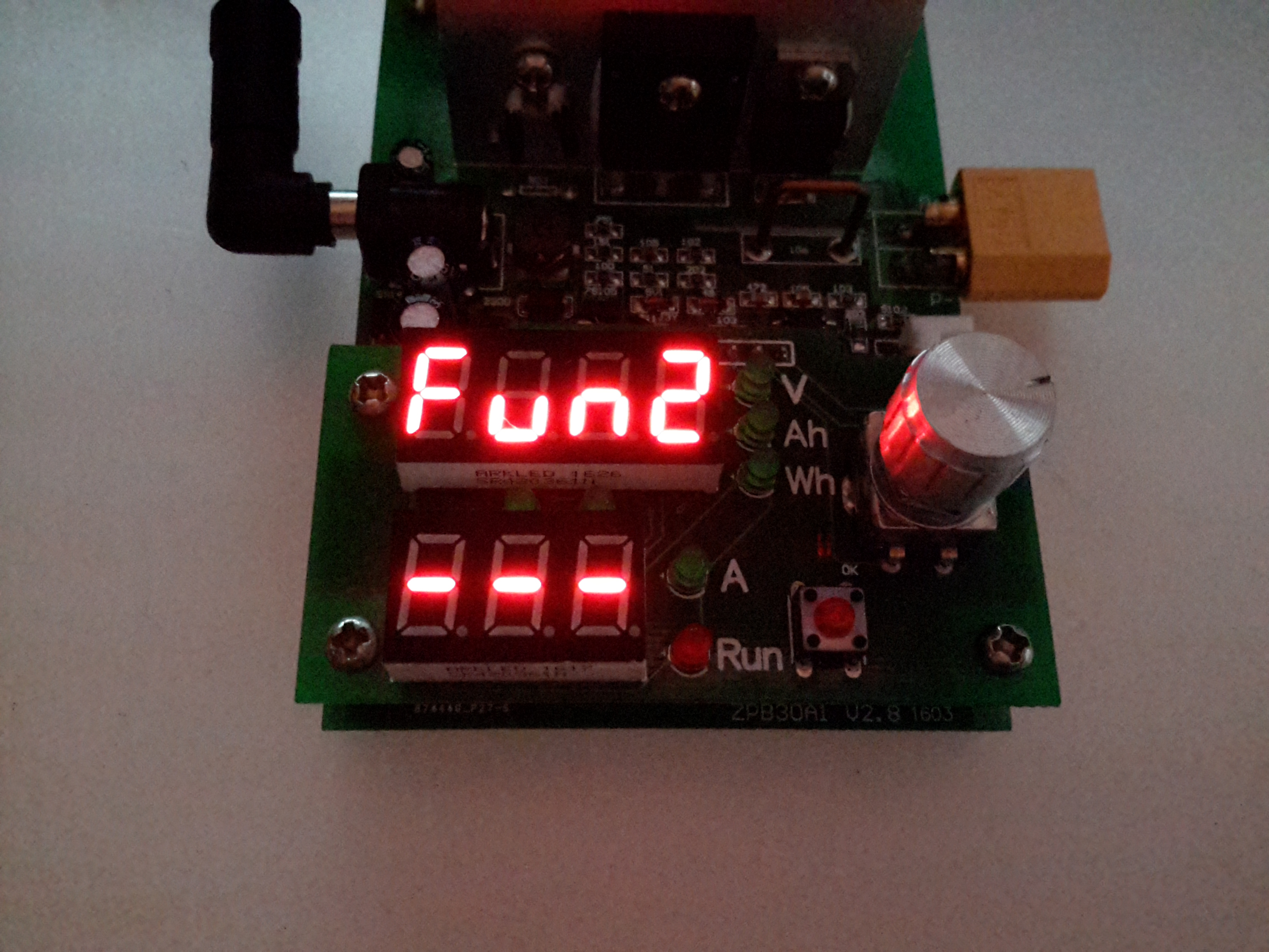
Function 2 – Battery Capacity Mode
The rotary encoder is used to select the option. Function 2 is battery capacity test mode.
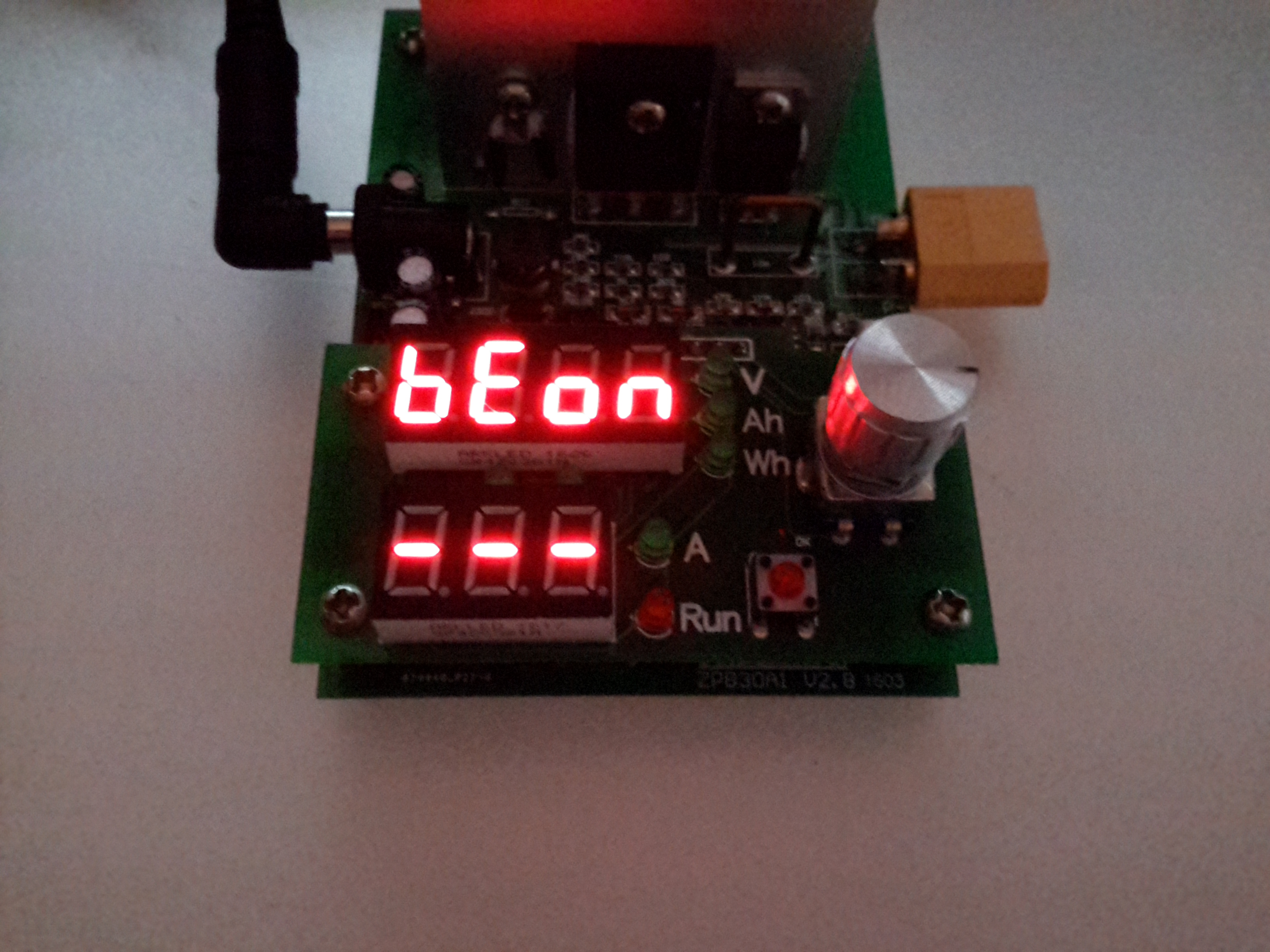
Beeper Mode
After the mode is selected, an option appears to either turn the beeper on or off.
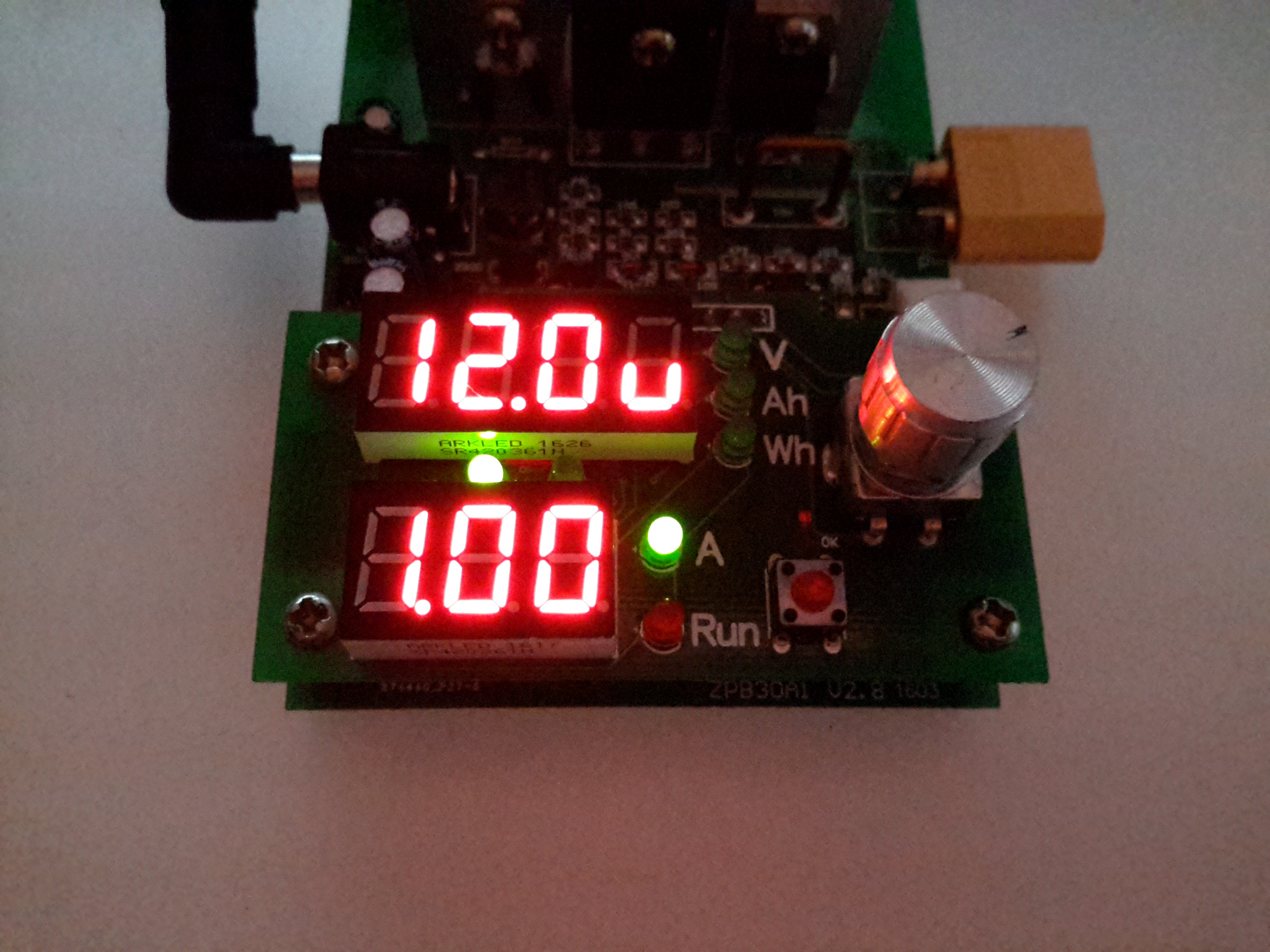
Amps Set
When in standby mode, the threshold voltage & the load current can be set. Here the Amps LED is lit, so the load current can be set. The pair of LEDs between the displays shows which digit will be changed. Pressing the encoder button cycles through the options.
Volts Set
With the Volts LED lit, the threshold voltage can be changed.
When in DC load mode (Fun1), the device will place a fixed load onto the power source until it’s manually stopped. The voltage setting in this mode is a low-voltage alarm. The current can be changed while the load is running.
When in battery discharge test mode (Fun2), the voltage set is the cutoff voltage – discharge will stop when this is reached. Like the DC load mode, the current can be changed when the load is running. After the battery has completed discharging, the capacity in Ah & Wh will be displayed on the top 7-segment. These results can be selected between with the encoder.
Below are tables with all the options for the unit, along with the error codes I’ve been able to decipher from the Chinese info available in various places online. (If anyone knows better, do let me know!).
Option
Function
Fun1
Basic DC Load
Fun 2
Battery Capacity Test
BeOn
Beeper On
BeOf
Beeper Off
Error Code
Meaning
Err1
Input Overvoltage
Err2
Low Battery Voltage / No Battery Present / Reverse Polarity
Err3
Battery ESR Too High / Cannot sustain selected discharge current
Err4
General Failure
Err6
Power Supply Voltage Too Low / Too High. Minimum 12v 0.5A.
otP
Overtemperature Protection
Ert
Temperature Sensor Failure / Temperature Too Low
ouP
Power Supply Overvoltage Protection
oPP
Load Power Protection
Tip Jar
If you’ve found my content useful, please consider leaving a donation by clicking the Tip Jar below!
All collected funds go towards new content & the costs of keeping the server online.