Posted on 4 Comments

AD9850 DDS VFO PCB & Schematic Layout

I recently came across a design for an Arduino controlled AD9850 DDS module, created by AD7C, so I figured I would release my Eagle CAD design for the PCB here.

It is a mainly single-sided layout, only a few links on the top side are needed so this is easy to etch with the toner transfer method.

My version uses an Arduino Pro Mini, as the modular format is much easier to work with than a bare ATMega 328.

RF output is via a SMA connector & has a built in amplifier to compensate for the low level generated by the DDS Module.

DDS VFO
DDS VFO

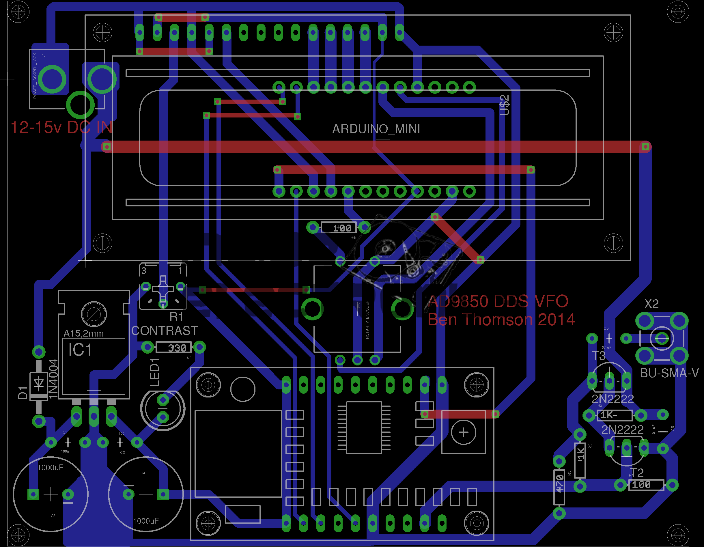
Version 2 Update: Added reverse polarity protection, added power indicator LED, beefed up tracks around the DC Jack.
[download id=”5571″]

Posted on 1 Comment

FE-5680A Rubidium Frequency Standard – Initial Teardown

Physics Package
Physics Package

Here is a quick look inside the FE-5060A Rubidium Frequency Standard. Above you can see the entire physics package, with the rubidium lamp housing on the right hand side. The ribbon cable running into the resonator cavity has the power & signal traces for the internal heater, temperature sensor & Helmholtz coil.

Lamp End
Lamp End

Here is the lamp end of the physics package, with the voltage regulator & RF driver for the lamp. The FETs soldered to the back of the housing are being used as heaters to maintain a constant temperature on the lamp in operation.
The temperature sensor can be seen between the two FETs, with a single copper wire running around the housing to connect to it.

Main frequency synth board. This contains the RS-232 interface & the AD9830A from Analog Devices. This IC is a direct digital synthesizer & waveform generator.


Synthesizer Board
Synthesizer Board
Posted on Leave a comment

XM2000 Marine VHF Radio

Radio
Radio

Here is an old XM2000 marine VHF tranciever.

Internal View
Internal View

Here is the casing split, with the main CPU board & display on the right, & the RF tranciever board on the left.

Main CPU
Main CPU

View of the main CPU board, with the mic & loudspeaker on the right hand side.
The channel display is on the reverse side of the PCB.

RF Board
RF Board

View of the RF board, with it’s brass shielding attached. This radio will transmit at 5W max.

RF Shields Removed
RF Shields Removed

Shielding removed, power regulation bottom right corner of the board, tranciever on the left.

PCB Front
PCB Front

CPU board removed from the casing, showing the LCD & the user buttons to the left.

Posted on Leave a comment

Marmitek Gigavideo 30

Antenna
Antenna

Here is a Marmitek Gigavideo 30 2.4GHz wireless video transmitter, has a receiver paired which will be uploaded shortly. Here is a view of the antennae, the large flat one being the 2.4GHz directional, the whip antenna possibly performing IR relay functions for the remote control.

Bottom Label
Bottom Label

For all those interested, here’s the bottom label.

PCB Top
PCB Top

The top cover removed reveals the main PCB. Big metal can is the RF transmitter circuitry. was encapsulated circuitry below that looks like an FM modulator for the whip antenna. Big TO220 package on heatsink is a LM7805 5-Volt regulator for the transmitter module.

These units work fantastically well when the antennas are aligned properly, at a decent range, however, they do have a nasty habit of doubling as a very effective WiFi LAN jammer.

Posted on Leave a comment

Belkin PCMCIA Wi-Fi Card

Top label
Top label

Here is an old Belkin Wireless G network card. This is a PCMCIA version.

Bottom Label
Bottom Label

Here is the bottom of the device, with all the details.

Antenna
Antenna

Plastic antenna cover removed, showing the pair of 2.4GHz etched antennae. There is a pair of LEDs on the upper left of the PCB showing activity & link status.

PCB
PCB

Overall view of the PCB, antennae on the left, RF chipset in centre, WiFi controller IC on right, and PCMCIA socket on far right. Can below wireless controller is a quartz crystal for the clock.

Chipset
Chipset

Closeup of the chipset, a Ralink RT2560F wireless controller on the right & a RT2525L transceiver on the left.

Posted on Leave a comment

Nokia 7110

Front
Front

Another phone from the mid 90s. This is the nokia 7110.

Slider Open
Slider Open

Here the slider is open showing the keypad.

Battery Removed
Battery Removed

Here the battery is removed, a Li-Ion unit.

Battery
Battery

The battery cell & protection circuit removed from the casing.

Rear Of PCB
Rear Of PCB

This is the rear of the PCB removed from the housing. Data & charging ports on the right hand side f the board.

Front Of PCB
Front Of PCB

Front of the PCB with the RF sections at the left hand side & the keypad contacts on the right.

RF Sections
RF Sections

Closeup of the RF sections of the board, big silver rectangular cans are VCO units.

SIM Connector
SIM Connector

Closeup of the top rear section of the PCB, with SIM cnnector, battery contacts, IR tranciever at the far left. Bottom centre is the external antenna connector.

CPU
CPU

The logic section of the board, Large chip is CPU, to right of that is the ROM storing the machine code. Other chips are unknown custom parts.

Mic & Speaker
Mic & Speaker

The Mic & the loudspeaker removed from it’s housing.

LCD
LCD

LCD from the front of the unit, SPI interfaced. Flex PCB also contains the power button, loudspeaker contacts & a temperature sensor.

Scroll Wheel
Scroll Wheel

The scroll wheel removed from the front housing.

Vibra-Motor
Vibra-Motor

Tiny vibration motor removed from the rear housing, alerts the user to a text or phone call.

Posted on Leave a comment

Dremel MultiPro

Front
Front

Here we have a Dremel MultiPro rotary tool, a main powered 125W 33,000RPM bit of kit.

Motor Assembly
Motor Assembly

Here the field & controller assembly is removed from the casing.

Armature
Armature

Here is the armature, which rotates at up to 33,000RPM. The brushes rise against the commutator on the left, next to the bearing, the cooling fan is on the right hand side on the power output shaft, the chuck attaches at the far right end of the shaft.

Speed Controller & Brush Box

Here is the speed controller unit, inside is an SCR phase angle speed controller, to vary the speed of the motor from 10,000RPM to the full rated speed of 33,000RPM.

Mains Filter
Mains Filter

This is the mains filter on the input to the unit, stops stray RF from the motor being radiated down the mains cable.

Posted on Leave a comment

Ericsson GA628

Front
Front

Here is a phone from the mid 90s, the Ericsson GA628. Here visible is the front of the unit with keypad, & single line monochrome LCD for number display.

Battery & Rear
Battery & Rear

Here the battery is removed from the phone, showing the SIM card socket. At the top under the antenna stub is the socket for an external antenna.

Front Removed
Front Removed

Here the front is removed from the phone, PCB on left, rear of keypad on right. Microphone is at bottom of keypad, with speaker at the top. Top right of the PCB is the ringer buzzer, left is shield for RF amplifier.

Main PCB
Main PCB

Here is the back of the main PCB, RF sections on left & centre. Processing & memory on right.

Battery
Battery

This phone had a Ni-Mh battery, before Li-Ion batteries were introduced.

LCD
LCD

The LCD from the front of the phone is shown here. A simple dot matrix single line unit.