Posted on Leave a comment

Wearable Raspberry Pi Part 2 – Power Supply

All Fitted
All Fitted

Progress is finally starting on the power supply unit for the Pi, fitted into the same case style as the Pi itself, this is an 8Ah Li-Poly battery pack with built in voltage regulation.

Regulator Boards
Regulator Boards

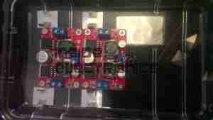
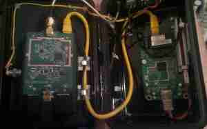
Here are the regulators, fixed to the top of the enclosure. These provide the 12v & 5v power rails for the Pi unit, at a max 3A per rail.

Battery Pack
Battery Pack

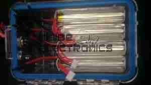
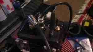
In the main body of the case the battery pack is fitted. This is made up of 4 3-cell Li-Poly RC battery packs, rated at 2Ah each. All wired in parallel this will provide a total of 8Ah at 12.6v when fully charged.

Powered Up
Powered Up

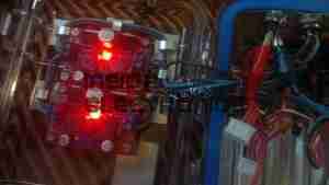
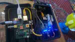
Here the regulators are powered up from a 13v supply for testing. I have discovered at full load these modules have very bad ripple, so I will be adding extra smoothing capacitors to the power rails to compensate for this.

I/O
I/O

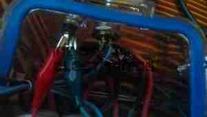
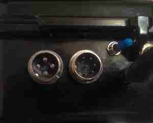
Here are the connectors on the top of the unit, outputting the two power rails to the Pi & the DC barrel jack that will be used to charge the pack.


Posted on 3 Comments

Wearable Raspberry Pi Part 1

Overview
Overview

Here is the project I’m currently working on. A completely wearable computing platform based on the Raspberry Pi & the WiFi Pineapple.

Above can be seen the general overview of the current unit.

On the left:

  • Alfa AWUS036NHA USB High Power WiFi Network Interface
  • 512MB Model B Raspberry Pi, 16GB SD card, running Raspbian & LXDE Desktop. Overclocked to 1GHz.

On the right:

  • WiFi Pineapple router board
  • USB 3G card.

The WiFi, Pineapple & 3G all have external antenna connections for a better signal & the whole unit locks onto the belt with a pair of clips.
The Raspberry Pi is using the composite video output to the 7″ LCD I am using, running at a resolution of 640×480. This gives a decent amount of desktop space while retaining readability of the display.

The case itself is a Pelican 1050 hard case, with it’s rubber lining removed. The belt clips are also a custom addition.

Connections
Connections

Here are the connections to the main unit, on the left is the main power connector, supplying +5v & +12v DC. The plug on the right is an 8-pin connection that carries two channels of video, mono audio & +12v power to the display.
Currently the only antenna fitted is the 3G.

Connectors
Connectors

Closeup of the connections for power, audio & video. The toggle switch is redundant & will soon be replaced with a 3.5mm stereo jack for headphones, as an alternative to the mono audio built into the display.

Test Run
Test Run

Current state of test. Here the unit is running, provided with an internet connection through the Pineapple’s 3G radio, funneled into the Pi via it’s ethernet connection.

Pi Goodness!
Pi Goodness!

Running on a car reversing camera monitor at 640×480 resolution. This works fairly well for the size of the monitor & the text is still large enough to be readable.


Stay tuned for Part 2 where I will build the power supply unit.


Posted on Leave a comment

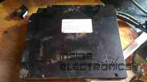
Routemaster Control Unit

This is the control unit for a Routemaster system, that downloads traffic information for the area local to the vehicle.

Unit Overview
Unit Overview

Here is an overview of the unit, in it’s aluminium box.


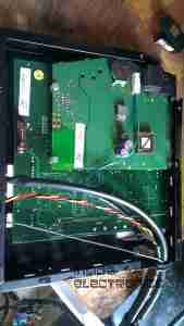
Here is the unit with the top cover removed, showing the pair of PCBs. The bottom PCB is the main control PCB, the top one holds an IC similar to a SIM card & part of the radio.

Cover Removed
Cover Removed


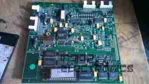
Main PCB Top
Main PCB Top

Here is the main PCB removed from the casing, contains the program ROM & microcontroller. for the system


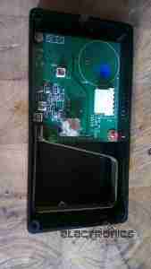
Daughtercard view. This holds another programmed CPLD, the custom SIM-like IC & the RTC battery, along with some power conversion circuitry.

Daughterboard Top
Daughterboard Top


Radio Receiver
Radio Receiver

This is the radio receiver, looks to be AM, the large loop antenna can be seen at the bottom of the box.

Posted on Leave a comment

XM2000 Marine VHF Radio

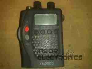
Radio
Radio

Here is an old XM2000 marine VHF tranciever.

Internal View
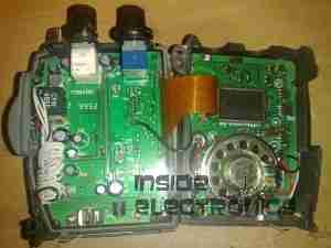
Internal View

Here is the casing split, with the main CPU board & display on the right, & the RF tranciever board on the left.

Main CPU
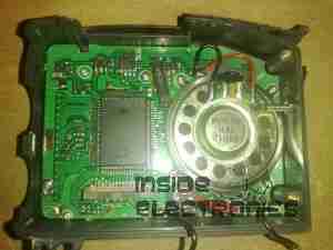
Main CPU

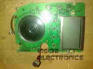
View of the main CPU board, with the mic & loudspeaker on the right hand side.
The channel display is on the reverse side of the PCB.

RF Board
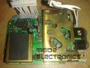
RF Board

View of the RF board, with it’s brass shielding attached. This radio will transmit at 5W max.

RF Shields Removed
RF Shields Removed

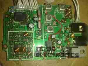
Shielding removed, power regulation bottom right corner of the board, tranciever on the left.

PCB Front
PCB Front

CPU board removed from the casing, showing the LCD & the user buttons to the left.

Posted on Leave a comment

The Finest Hour

Reprinted from The Pirate Bay. Thought this deserved as much net coverage as possible.


February 2011, MAFIAA Lobbyists began a massive attack against the European Union.

Defending the union were seeds and peers of The Pirate Bay along with the Telecomix, Anons, and the Pirate parties. The MAFIAA relied on an aggressive battle plan, utilizing modern communications such as radio and telefax to direct troops in the field. The Allies, for their part, assumed a defensive posture, just as they had done at the start of World Internets War of 2003, and in many cases still relied on irc.

As a result, the MAFIAA blitzkrieg caught the Allies off-guard. MAFIAA’s smooth talks and bribes against key players in the EU staged a surprise attack, then turned northward and soon surrounded the bulk of the EU headquarters in Belgium.

After just a few weeks of battle, MAFIAA’s armies had conquered the right, the left and the liberal parties.

I expect that the Battle of Internets is about to begin. Upon this battle depends the survival of an Uncensored civilization! Upon it depends our own free life, and the long continuity of our sites and our trackers. The whole fury and might of the enemy will very soon be turned on us.

MAFIAA knows that they will have to break us in Brussels or lose the war. If we can stand up to them, all Europe may be free and the life of the world may move forward into broad, sunlit uplands. But if we fail, then the whole world, including all that we have known and cared for, will sink into the abyss of a new Dark Age made more sinister, and perhaps more protracted, by the lights of perverted science.

Let us therefore brace ourselves to our duties, and so bear ourselves that if the free internets and its multitude of sites last for a thousand years, citizens will still say, This was their finest hour.

Yours, Winston Bay.

Full news article here.
 

Posted on Leave a comment

Logitech Cordless Ball Mouse

Top
Top

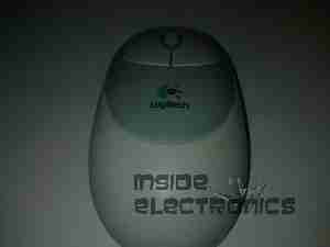
This is an old legacy wireless mouse from Logitech. This uses a ball rather than optical technology.

Bottom
Bottom

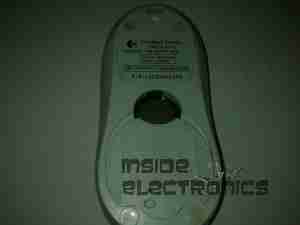
Bottom of the mouse, showing the battery cover & the mouse ball.

PCB Bottom
PCB Bottom

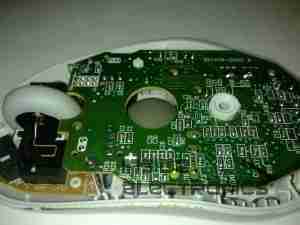
Top removed from the mouse, showing the PCB inside. The smaller PCB on the left supports the microswitches for the buttons & mouse wheel.

Switches
Switches

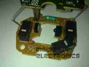
Closeup of small PCB showing the microswitches & the IR LED & phototransistor pair for the mouse wheel encoder.

Main PCB
Main PCB

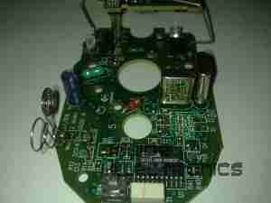
View of main PCB, with interface IC lower right. Pair of quartz crystals provide clocking for the transmitter & internal µC.
Battery contacts are on lower left of the PCB. At the top are the IR pairs for the X & Y axis of the mouse ball.

Encoder Pairs
Encoder Pairs

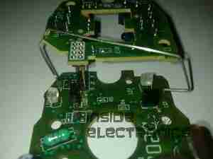
Closeup of the pairs of IR LEDs & phototransistors that make up the encoders for X/Y movement of the mouse, together with the slotted wheels in the mouse base that rotate with the ball. Steel wire around the smaller PCB is the antenna.

Posted on Leave a comment

Marmitek Gigavideo 30

Antenna
Antenna

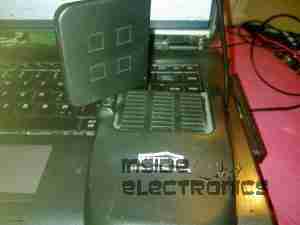
Here is a Marmitek Gigavideo 30 2.4GHz wireless video transmitter, has a receiver paired which will be uploaded shortly. Here is a view of the antennae, the large flat one being the 2.4GHz directional, the whip antenna possibly performing IR relay functions for the remote control.

Bottom Label
Bottom Label

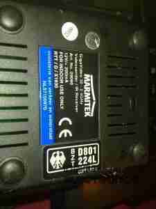
For all those interested, here’s the bottom label.

PCB Top
PCB Top

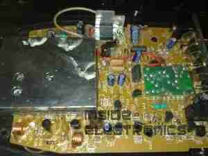
The top cover removed reveals the main PCB. Big metal can is the RF transmitter circuitry. was encapsulated circuitry below that looks like an FM modulator for the whip antenna. Big TO220 package on heatsink is a LM7805 5-Volt regulator for the transmitter module.

These units work fantastically well when the antennas are aligned properly, at a decent range, however, they do have a nasty habit of doubling as a very effective WiFi LAN jammer.

Posted on Leave a comment

Southwestern Bell Freedom Phone

Phone
Phone

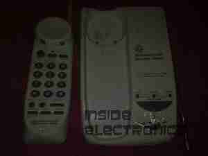
This is an old cordless landline phone, with dead handset batteries.

Handset Radio Board
Handset Radio Board

Here’s the handset with the back removed. Shown is the radio TX/RX board, underneath is the keyboard PCB with the speaker & mic. All the FM radio tuning coils are visible & a LT450GW electromechanical filter.

Handset Radio Board Bottom

Radio PCB removed from the housing showing the main CPU controlling the unit, a Motorola MC13109FB.

Keypad Board
Keypad Board

The keypad PCB, with also holds the microphone & speaker.

Handset Keypad Board Bottom

Bottom of the keypad board, which holds a LSC526534DW 8-Bit µC & a AT93C46R serial EEPROM for phone number storage.

Base Main Board
Base Main Board

Here’s the base unit with it’s top cover removed. Black square object on far right of image is the microphone for intercom use, power supply section is top left, phone interface bottom left, FM radio is centre. Battery snap for power backup is bottom right.
Power Supply Section

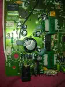
PSU section of the board on the left here, 9v AC input socket at the bottom, with bridge rectifier diodes & main filter capacitor above. Two green transformers on the right are for audio impedance matching. Another LT450GW filter is visible at the top, part of the base unit FM transceiver.
ICs
ICs

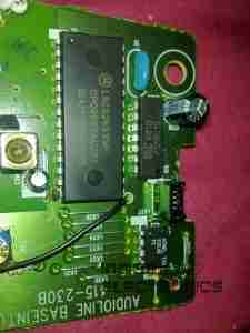
Another 8-bit µC, this time a LSC526535P, paired with another AT93C46 EEPROM. Blue blob is 3.58MHz crystal resonator for the MCU clock. The SEC IC is a KS58015 4-bit binary to DTMF dialer IC. This is controlled by the µC.

Base Main Board Bottom

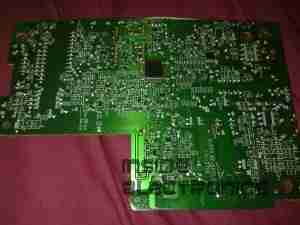
Underside of the base unit Main PCB, showing the matching MC13109FB IC for the radio functions.

Posted on 2 Comments

Current Cost ‘Envi’ CC128 Power Meter

Display Unit
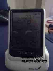
Display Unit

This is the Current Cost CC128 Real Time Power Meter. Shown here is the display unit, British Gas issued these free to some customers.
This unit measures current power draw in Watts, cost of power currently being used (requires unit price to be set), overall kWh usage over the past 1, 7 or 30 days & power trends during the day, night & evening. Also displays current time & current room temperature.

Display PCB
Display PCB

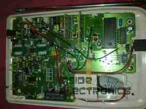
Here the front panel of the display has been un-clipped. At the bottom are the RJ-45 serial port & power connections.
This unit uses a PIC micro-controller as it’s CPU (PIC18F85J90) Just above & left of the CPU is the 433MHz SPD radio receiver module. The chips on the right of the CPU are a 25LC128 SPI serial EEPROM for data storage & a 74HC4060 14 stage binary counter, to which is connected the 32kHz clock crystal. The red wire around the top of the display is the antenna for the radio receiver.

For more info on the CC128 in general, the serial port & software for computer data logging, see this link
See this link for Current Cost’s list of software

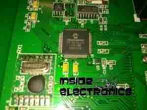
Processor & Radio
Processor & Radio

Closeup of the ICs on the mainboard.

Transmitter Unit
Transmitter Unit

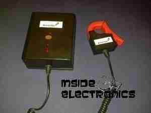
Here we have the transmitter unit, with Current Transformer (CT). The red clamp fits around one of the electric meter tails & read the current going to the various circuits. This unit is powered by 2x D cells, rated at a life of 7 years.

Transmitter PCB
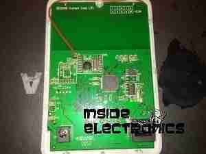
Transmitter PCB

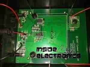
The PCB inside the transmitter. Again very minimal design, unknown controller IC, 433MHz radio transmitter on right hand side with wire antenna. Two barrel connectors on left hand side of board allow connection of up to two more CT clamps for measurement of 3-phase power. Centre of board is unmarked header. (ICSP?)

Current Transformer
Current Transformer

CT unit. Inside is a coil of wire & an iron core which surrounds the cable to be measured.