I have finally got round to designing the balancing circuitry for my ultracapacitor banks, which have a total voltage of 15v when fully charged. The 2600F capacitors have a max working voltage of 2.5v each, so to ensure reliable operation, balancing is required to make sure that each capacitor is charged fully.
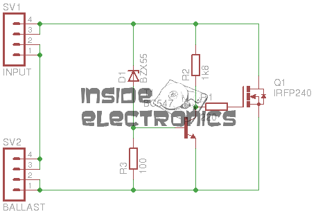
The circuit above is a simple shunt regulator, which uses a 2.2v zener diode to regulate the voltage across the capacitor.
A 10W 1Ω resistor is connected to the BALLAST header, while the capacitor is connected across the INPUT. Once the voltage on the capacitor reaches 2.6v, the MOSFET begins to conduct, the 1Ω resistor limiting current to ~2.6A.
Each capacitor in the series string requires one of these connected across it.
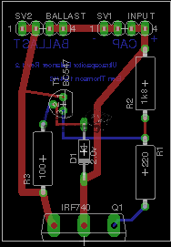
PCB
Below is a link to the Eagle project archive for this. Includes schematic, board & gerber files.
A few modifications were required to the SMPS modules to make the power rails stable enough to run the Pi & it’s monitor. Without these the rails were so noisy that instability was being caused.
I have replaced the 100µF output capacitors & replaced them with 35v 4700µF caps. This provides a much lower output ripple.
There are also heatsinks attached to the converter ICs to help spread the heat.
Here is the project I’m currently working on. A completely wearable computing platform based on the Raspberry Pi & the WiFi Pineapple.
Above can be seen the general overview of the current unit.
On the left:
Alfa AWUS036NHA USB High Power WiFi Network Interface
512MB Model B Raspberry Pi, 16GB SD card, running Raspbian & LXDE Desktop. Overclocked to 1GHz.
On the right:
WiFi Pineapple router board
USB 3G card.
The WiFi, Pineapple & 3G all have external antenna connections for a better signal & the whole unit locks onto the belt with a pair of clips.
The Raspberry Pi is using the composite video output to the 7″ LCD I am using, running at a resolution of 640×480. This gives a decent amount of desktop space while retaining readability of the display.
The case itself is a Pelican 1050 hard case, with it’s rubber lining removed. The belt clips are also a custom addition.
Connections
Here are the connections to the main unit, on the left is the main power connector, supplying +5v & +12v DC. The plug on the right is an 8-pin connection that carries two channels of video, mono audio & +12v power to the display.
Currently the only antenna fitted is the 3G.
Connectors
Closeup of the connections for power, audio & video. The toggle switch is redundant & will soon be replaced with a 3.5mm stereo jack for headphones, as an alternative to the mono audio built into the display.
Test Run
Current state of test. Here the unit is running, provided with an internet connection through the Pineapple’s 3G radio, funneled into the Pi via it’s ethernet connection.
Pi Goodness!
Running on a car reversing camera monitor at 640×480 resolution. This works fairly well for the size of the monitor & the text is still large enough to be readable.
Stay tuned for Part 2 where I will build the power supply unit.
Just a quickie to note down the current progress of another project – Ultracapacitors.
Pictured right is a bank of 6 2.5v 2600F Maxwell Boostcaps, for a total of 15v at 433.333F. A total energy storage of 48.7kJ.
Coming soon will be the inclusion of charge balancing, using Zener diodes & integrating a DC-DC converter on the output to hold the bank voltage at 12v when being used.
This unit was bought from eBay to experiment with Magnetic Stripe cards, for little money. This unit is capable of reading & writing all 3 tracks, & both Hi-Co & Lo-Co card types.
Interfaced to a PC through USB, this has a built in PL2303 USB-Serial IC & requires 3A at 9v DC to operate.
The 3 Indicator LEDs on the top of the unit can be toggled by the included software for Power/OK/Fault condition signalling.
Unit Bottom
Bottom of the unit with the model labels.
Model Label
Closeup of the model label & serial number.
PCB Bottom
Here the bottom cover has been removed, showing the main PCB. The pair of large ICs bottom center interface with the magnetic heads. The IC above them has had the markings sanded off.
USB-Serial Interface
Closeup of the Prolific PL-2303 USB-Serial converter IC.
PCB Top
Here the connections to the R/W heads are visible, current limiting resistors at the left for the write head, a pair of signal relays, a pair of optoisolators & a LM7805 linear voltage regulator.
LEDs
Here is the trio of indicator LEDs on a small sub-board.
Frame Bottom
The PCB has been removed from the main frame here, the only component visible is the rotary encoder.
Rotary Encoder
The rotary encoder has a rubber wheel fitted, which reads the speed of the card as it is being swiped for writing. This allows the control logic to write the data to the stripe at the correct rate for the speed of the card. This allows the unit to write cards from 5-50 inches per second speed.
The Write head is directly behind the rubber pressure roller.
Read/Write Heads
Here you can see the R/W head assembly. The write head is on the right, read on the left. When a card is written to, it immediately gets read by the second head for verification.
Here is an old electrochemical type carbon monoxide detector cell, from Monox. Hole in the centre is the inlet for the gas under test. DO NOT TRY THIS AT HOME! Electrochemical cells contain a substantial amount of sulphuric acid, strong enough to cause burns.
This is a type of fuel cell that instead of being designed to produce power, is designed to produce a current that is precisely related to the amount of the target gas (in this case carbon monoxide) in the atmosphere. Measurement of the current gives a measure of the concentration of carbon monoxide in the atmosphere. Essentially the electrochemical cell consists of a container, 2 electrodes, connection wires and an electrolyte – typically sulfuric acid. Carbon monoxide is oxidized at one electrode to carbon dioxide while oxygen is consumed at the other electrode. For carbon monoxide detection, the electrochemical cell has advantages over other technologies in that it has a highly accurate and linear output to carbon monoxide concentration, requires minimal power as it is operated at room temperature, and has a long lifetime (typically commercial available cells now have lifetimes of 5 years or greater). Until recently, the cost of these cells and concerns about their long term reliability had limited uptake of this technology in the marketplace, although these concerns are now largely overcome. This technology is now the dominant technology in USA and Europe.
Rear
Rear of unit with connection pins. Hole here is to let oxygen into the cell which permits the redox reaction to take place in the cell when CO is detected, producing a voltage on the output pins.
Disassembled
Cell disassembled. The semi-permeable membrane on the back cover can be seen here, to allow gas into the cell, but not the liquid electrolyte out. Cell with the electrodes is on the right, immersed in sulphuric acid.
Platinum Electrode
Closeup of the electrode structure. Polymer base with a precious metal coating.
Old type ionization smoke alarm. Top of the device with the test button & sounder.
Bottom
Bottom of the device. Battery compartment in centre.
PCB
Internals of the smoke alarm. Main component visible is the Ionization chamber.
Sounder
Piezo sounder on inside of the top.
Ionization Chamber
Inside the Ionization Chamber. 1µCi Americium-241 alpha particle source in the centre.
The radiation passes through the chamber, between the pair of electrodes, ionizing the air & permitting a small current to pass between the electrodes.
Any smoke that enters the chamber absorbs the alpha particles, which reduces the ionization and interrupts this current, setting off the alarm.
To help make my system more efficient, a pair of switching regulators has been fitted, the one shown above is a Texas Instruments PTN78060 switchmode regulator module, which provides a 7.5v rail from the main 12v battery pack.
A Lot like the LM317 & similar linear regulators, these modules require a single program resistor to set the output voltage, but are much more efficient, around the 94% mark at the settings used here.
The 7.5v rail supplies the LM317 constant current circuit in the laser diode driver subsection. This increases efficiency by taking some voltage drop away from the LM317.
5v Regulator
The 7.5v rail also provides power to this Texas Instruments PTH08000 switchmode regulator module, providing the 5v rail for the USB port power.
The parts arrived for my adjustable laser diode driver! Components here are an LM317K with heatsink, 100Ω 10-turn precision potentiometer, 15-turn counting dial & a 7-pin matching plug & socket.
Driver Schematic
Here is the schematic for the driver circuit. I have used a 7-pin socket for provisions for active cooling of bigger laser diodes. R1 sets the maximum current to the laser diode, while R2 is the power adjustment. This is all fed from the main 12v Ni-Cd pack built into the PSU. The LM317 is set up as a constant current source in this circuit.
Installed
Here the power adjust dial & the laser head connector have been installed in the front panel. Power is switched to the driver with the toggle switch to the right of the connector.
Regulator
The LM317 installed on the rear panel of the PSU with it’s heatsink.
Connection
Connections to the regulator, the output is fully isolated from the heatsink & rear panel.
This is a HP PhotoSmart 375 portable photo printer. With built in card reader, screen & PictBridge.
Top of the printer showing the UI Buttons & Screen.
Front
Front of the unit, card reader slots at the top, Pictbridge USB connector at top left. Paper out slot at bottom. Cartridge door is on the right.
Cartridge Door
Here the cartridge door is open. Takes HP 95 Tri-Colour Inkjet Cartridge.
Battery Compartment
Battery compartment on the bottom of the unit. A Li-Ion battery pack can be installed here for mobile photo printing.
Bottom Label
Specifications label.
USB + Power
Power adaptor & USB connection for PC use.
Paper Tray
Rear door opened. Showing the paper feed tray.
Paper Feeder
Rear door has been removed in this shot. Paper feed roller & platen roller can be seen here.
Rear Cover Paper Feeder
Paper holder attached to rear door.
Top Cover
Bottom of the top cover, with connections for the buttons & LCD panel.
Main PCB
This is the main PCB of the unit. Controls all aspects of the printer. CPU in center, card reader sockets are along bottom edge. various support circuitry surrounds the CPU.
Rear
Rear shell has been removed here. Showing the main frame & the carriage drive motor on the left.
Carriage Drive
Closeup of the carriage drive motor & timing belt system. All the motors in this printer are DC servo motors, not steppers.
Main Drive Motor
Main drive motor, feeds paper, drives rollers, operates cleaning mechanism for the inkjets.
Shaft Encoder
Mainshaft encoder. Main drive motor is bottom right hand side with timing belt drive.
CPU
Closeup of the CPU. This is a Phillips ARM chip, unknown spec.
Card Reader Sockets
Detail of the card reader sockets, this unit takes all current types of Flash memory card.
This is the Current Cost CC128 Real Time Power Meter. Shown here is the display unit, British Gas issued these free to some customers.
This unit measures current power draw in Watts, cost of power currently being used (requires unit price to be set), overall kWh usage over the past 1, 7 or 30 days & power trends during the day, night & evening. Also displays current time & current room temperature.
Display PCB
Here the front panel of the display has been un-clipped. At the bottom are the RJ-45 serial port & power connections.
This unit uses a PIC micro-controller as it’s CPU (PIC18F85J90) Just above & left of the CPU is the 433MHz SPD radio receiver module. The chips on the right of the CPU are a 25LC128 SPI serial EEPROM for data storage & a 74HC4060 14 stage binary counter, to which is connected the 32kHz clock crystal. The red wire around the top of the display is the antenna for the radio receiver.
For more info on the CC128 in general, the serial port & software for computer data logging, see this link
See this link for Current Cost’s list of software
Processor & Radio
Closeup of the ICs on the mainboard.
Transmitter Unit
Here we have the transmitter unit, with Current Transformer (CT). The red clamp fits around one of the electric meter tails & read the current going to the various circuits. This unit is powered by 2x D cells, rated at a life of 7 years.
Transmitter PCB
The PCB inside the transmitter. Again very minimal design, unknown controller IC, 433MHz radio transmitter on right hand side with wire antenna. Two barrel connectors on left hand side of board allow connection of up to two more CT clamps for measurement of 3-phase power. Centre of board is unmarked header. (ICSP?)
Current Transformer
CT unit. Inside is a coil of wire & an iron core which surrounds the cable to be measured.
PIC18F85J90
Tip Jar
If you’ve found my content useful, please consider leaving a donation by clicking the Tip Jar below!
All collected funds go towards new content & the costs of keeping the server online.