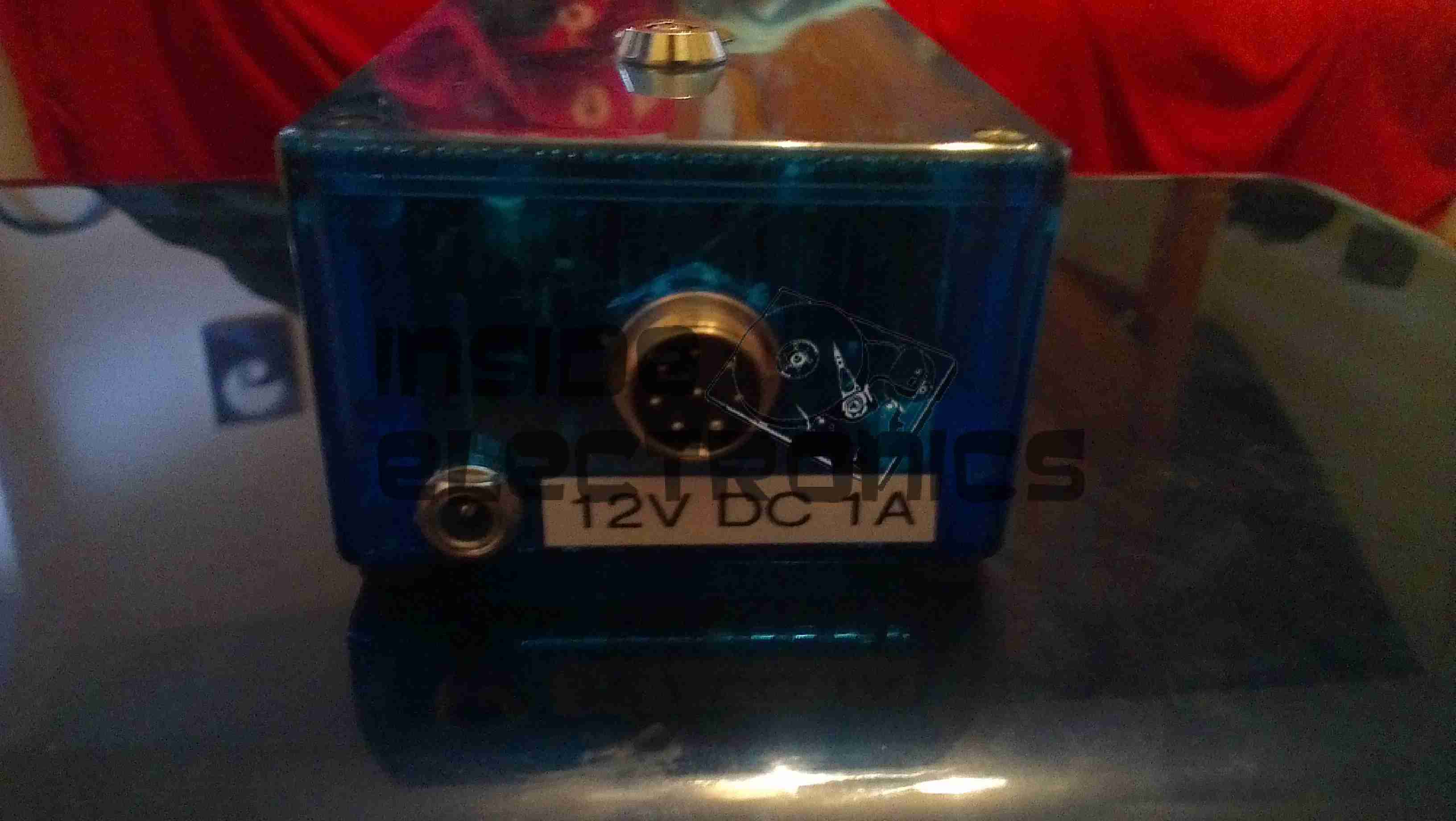
In preparation for my laser scanner project, I have modified my existing 445nm laser to accept a TTL blanking input. The laser driver is already enabled for this & just required an extra connection to interface with my laser scanner showboard. I have used an 8-pin connection to allow the same cable & interface to be used with an RGB laser system, when it arrives. The signals are as follows, from top centre, anti-clockwise:
Pin 1: +12v Power
Pin 2: Blue TTL
Pin3: GND
Pin 4: Green TTL
Pin 5: GND
Pin 6: Red TTL
Pin 7: GND
Centre: Power GND
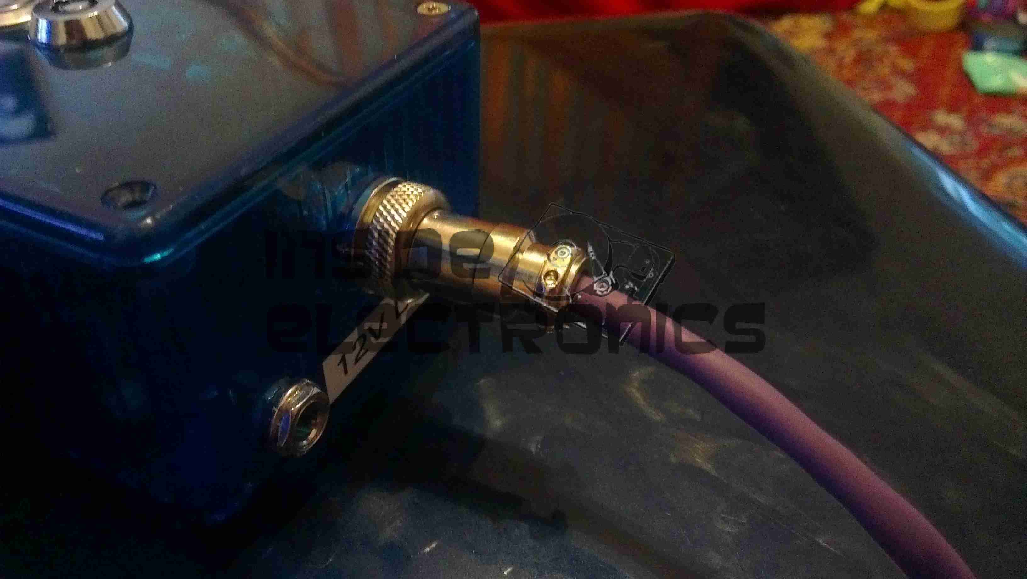
Custom TTL Cable
Here is the custom 8 core cable, which connects to the laser scanner show board. This cable allows the laser to be used for projection while still retaining the portable function & the keylock arming switch. When plugged in the cable bypasses the keyswitch & provides 12v DC direct to the laser driver.
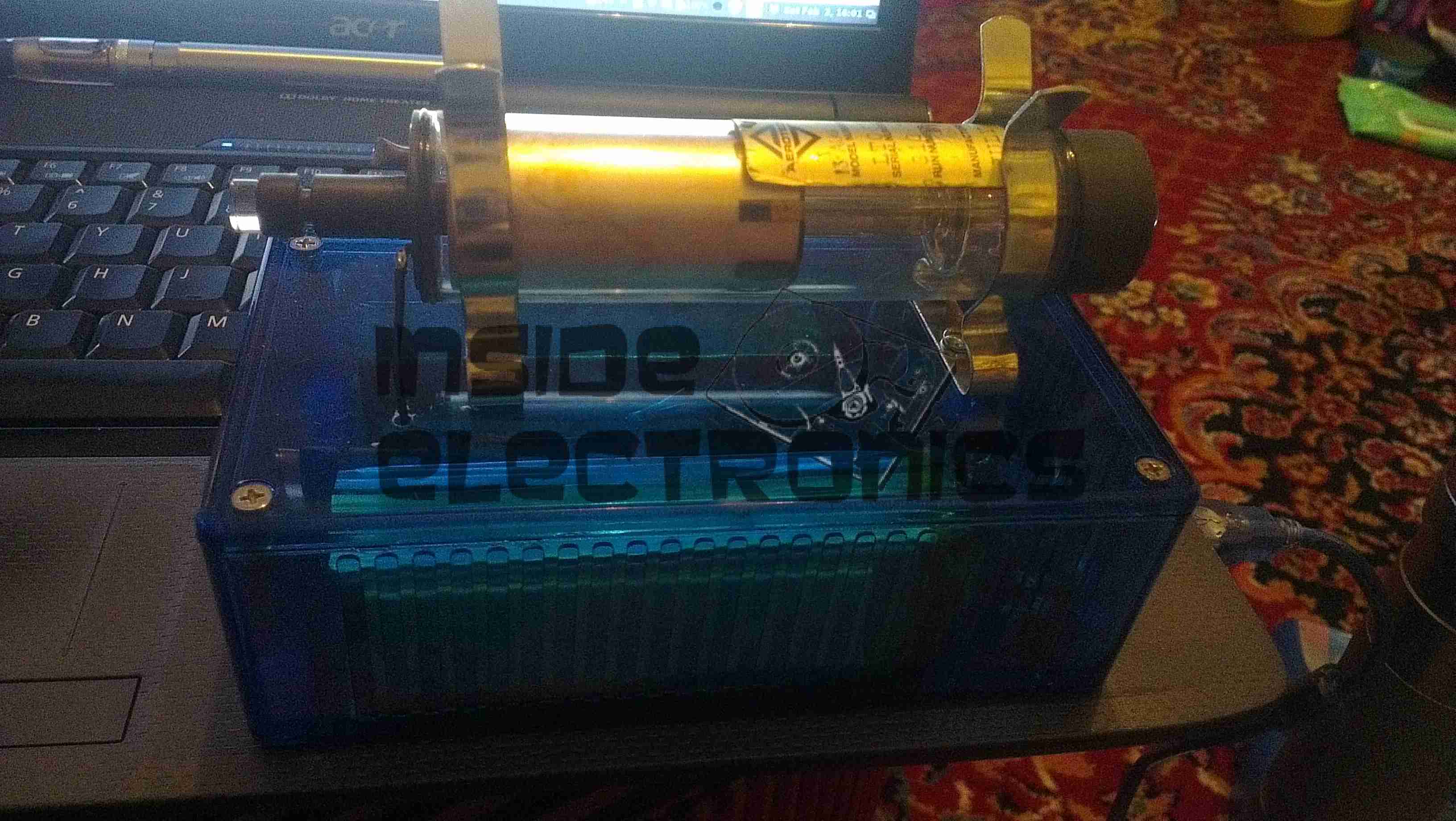
Having had a He-Ne laser tube for a while & the required power supply, it was time to mount the tube in a more sturdy manner. Above the tube is mounted with a pair of 32mm Terry Clips, with the power leads passing through the plastic top. The ballast resistor is built into the silicone rubber on the anode end of the tube. (Right).
Output power is about 1mW for this tube, which came from a supermarket barcode scanner from the 90’s. The tube is dated August 1993 & is manufactured by Aerotech.
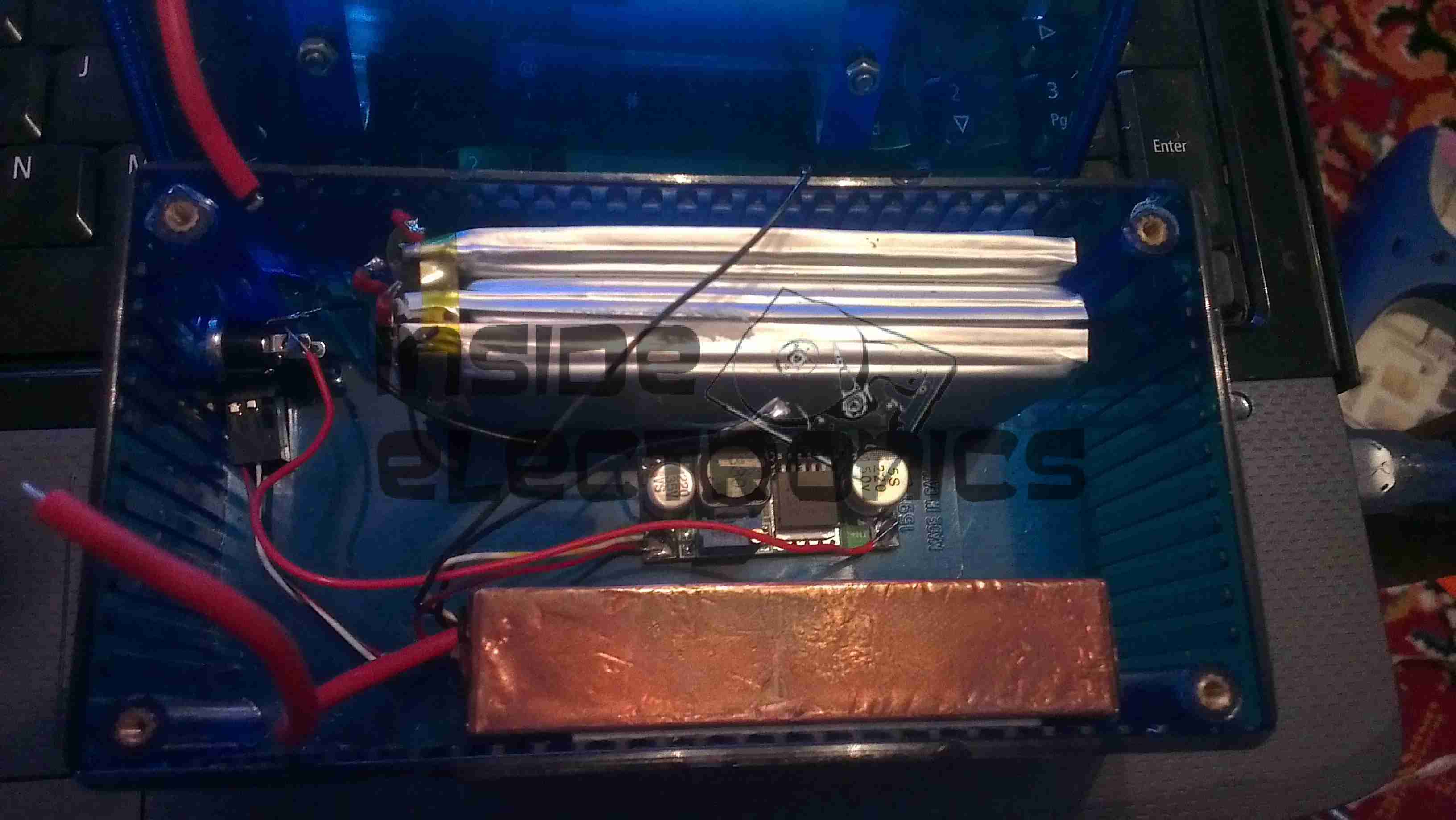
Internals
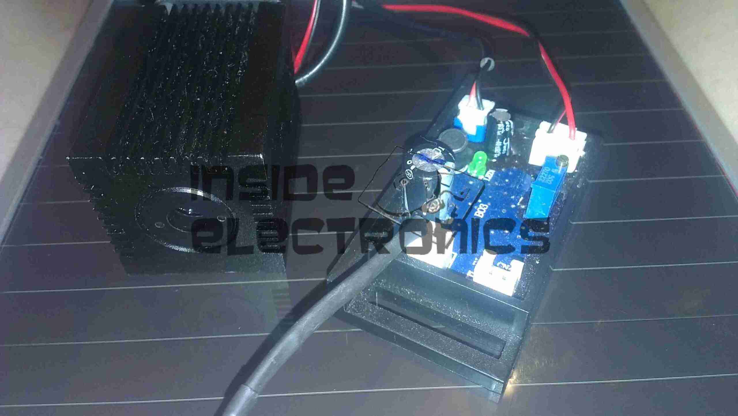
Inside the box is the usual 2.2Ah 12v Li-Po battery pack & the brick type He-Ne laser supply. The small circuit in the centre is a switchmode converter that drops the 12v from the battery pack to the 5v required for the laser supply.
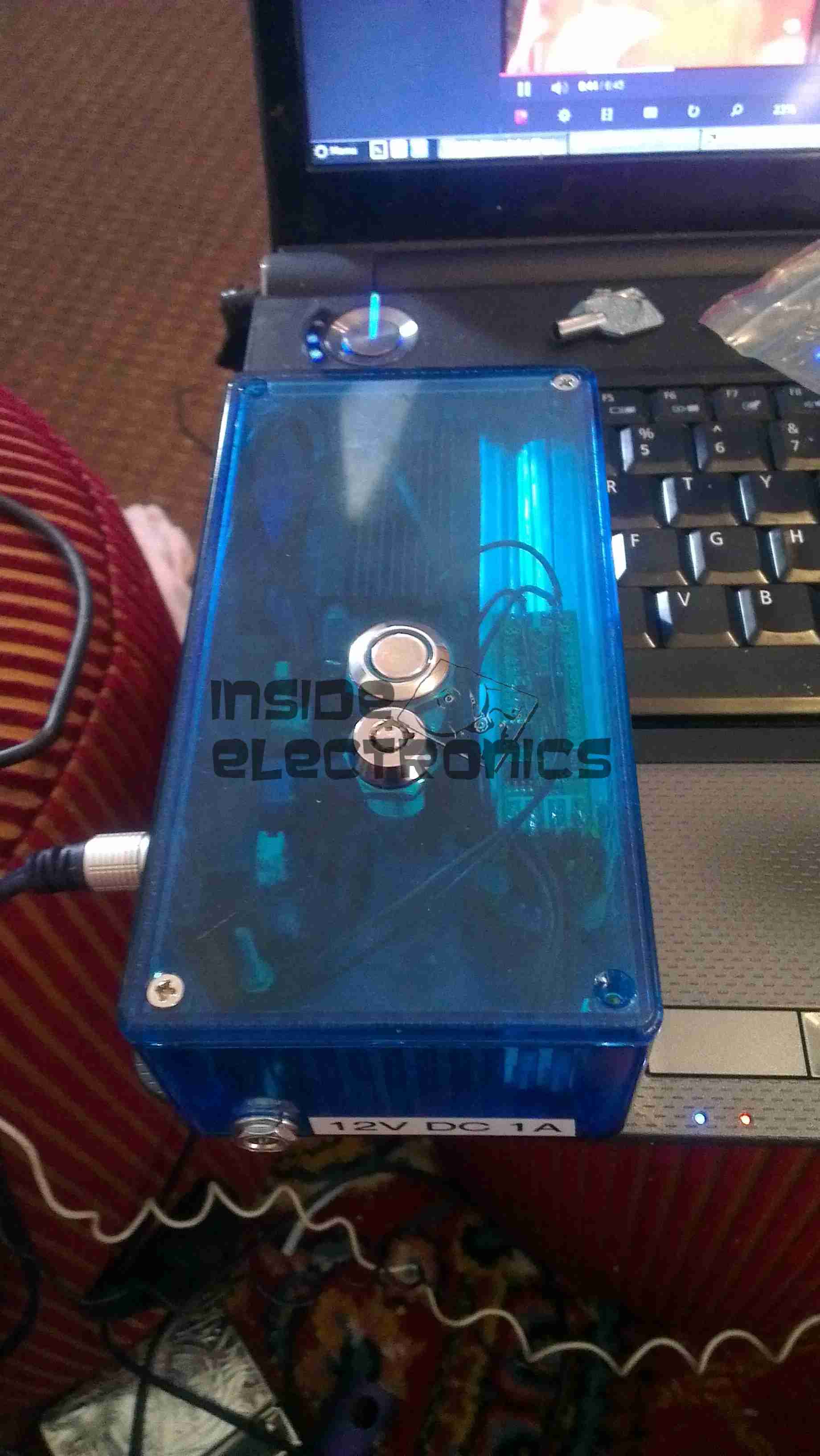
Here is a followup from the 1.5W laser module post.
The module has been fitted into a housing, with a 2.2Ah Li-Poly battery pack. Charging is accomplished with an external 12.6v DC power supply.
Above can be seen the pair of switches on the top, the keyswitch must be enabled for the laser to fire.
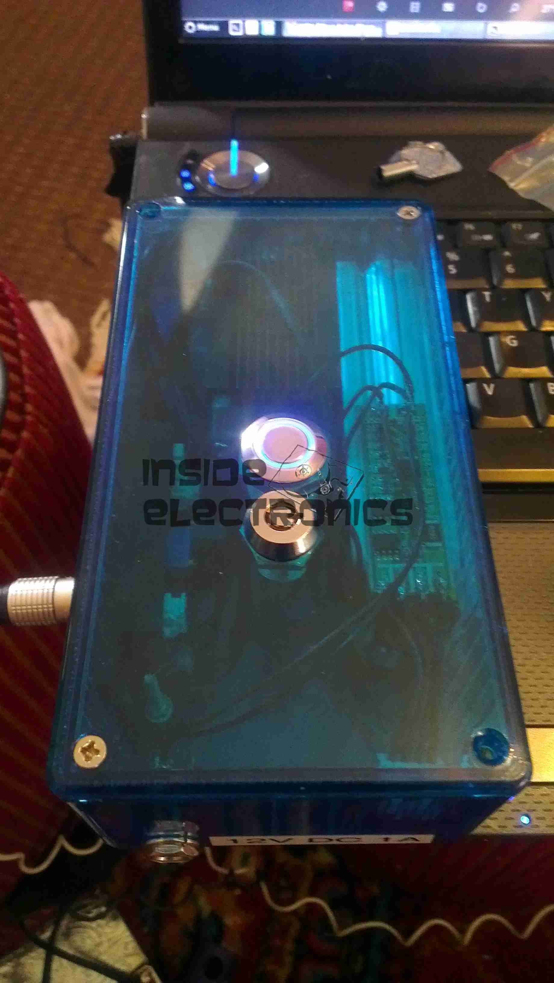
Armed
When armed, the ring around the push button illuminates blue, as a warning that the unit is armed.
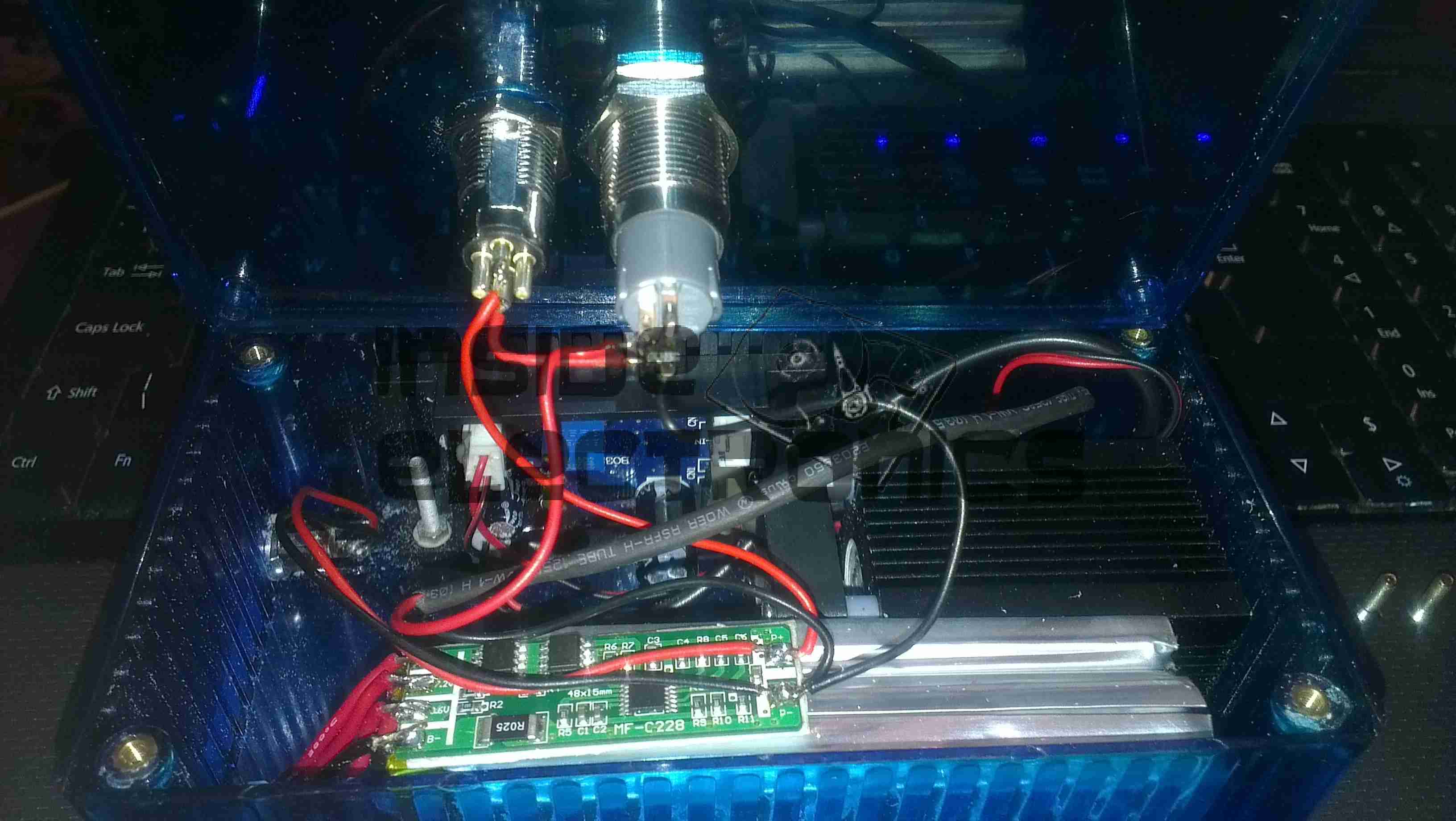
Switch Wiring
Inside the unit. The Li-Poly battery pack is at the bottom, with it’s protection & charging circuitry on the top. The switches are wired in series, with the LED connected to illuminate when the keyswitch is turned to the ON position.
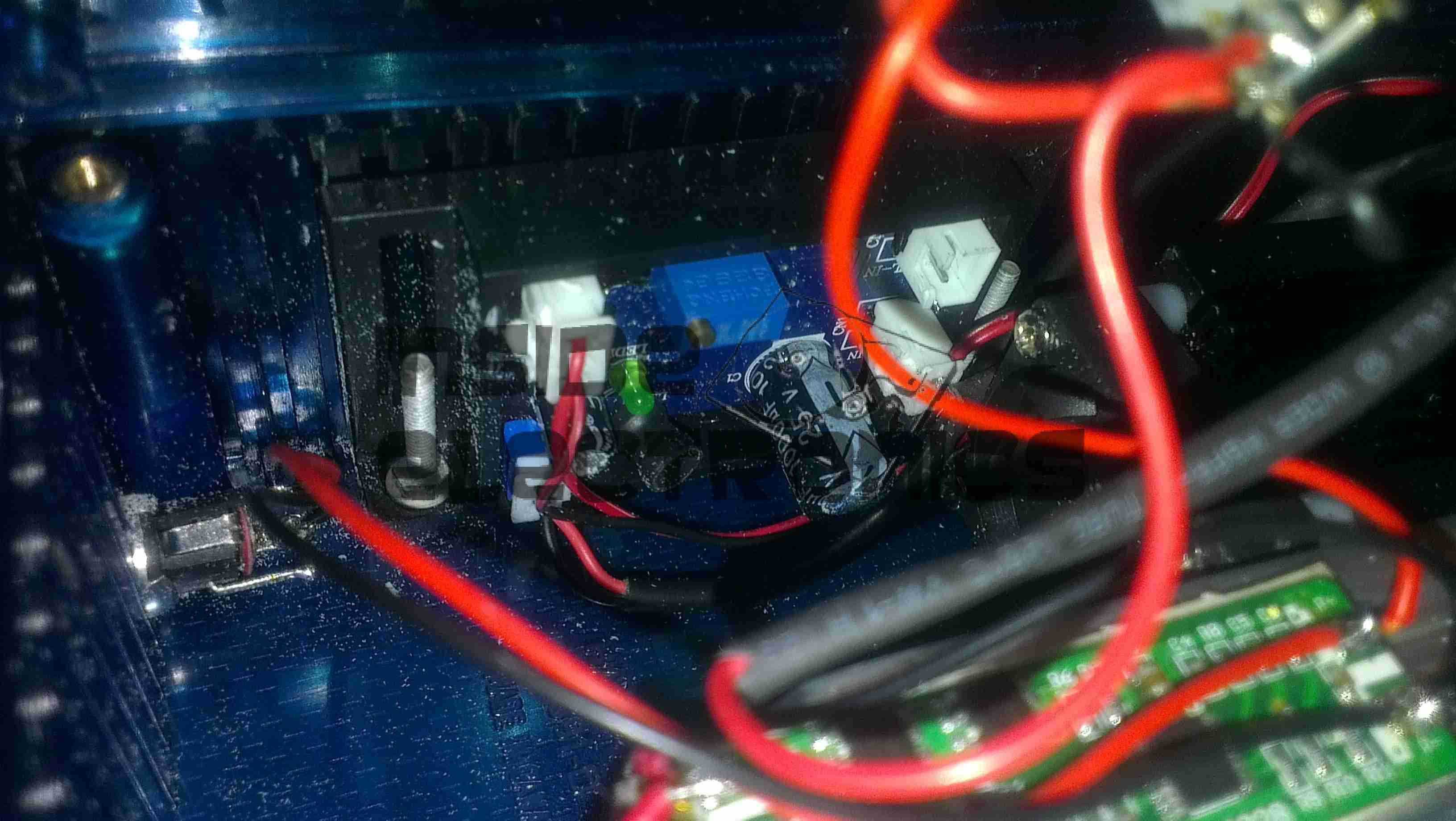
Laser Driver
The push button applies power to the laser driver module, which regulates the input power to safely drive the semiconductor laser in the aluminium heatsink housing.
Here are a few details of a valve amplifier I am building, using the valve related parts from a 1960’s reel to reel tape recorder.
This amplifier is based on an a Mullard ECL82 triode/pentode valve, with an EM84 magic eye tube for level indication.
Beginnings Of The Amplifier
Here the first components are being soldered to the tags on the valve holder, there are so few components that a PCB is not required, everything can be rats-nested onto the valve holders.
Progress
Progressing with the amplifier section componentry, all resistors are either 1/2W or 2W.
Valve Sockets Fitted
Here the valve holders have been fitted, along with the output transformer, DC smoothing capacitor & the filament wiring, into the top of the plastic housing. At this point all the components that complete the amplifier section are soldered to the bottom of the right hand valve holder.
Wiring
Starting the wiring between the valves & the power supply components. The volume control pot is fitted between the valve holders.
Valves Test Fit
The valves here are test fitted into their sockets, the aluminium can at the back is a triple 32uF 250v electrolytic capacitor for smoothing the B+ rail.
Amplifier Section First Test
First test of the amplifier, with the speaker from the 1960’s tape recorder from which the valves came from. the 200v DC B+ supply & the 6.3v AC filament supply is derived from the mains transformer in the background.
Magic Eye Tube Added
Here the magic eye tube has been fitted & is getting it’s initial tuning to the amplifier section. This requires selecting combinations of anode & grid resistors to set the gap between the bars while at no signal & picking a coupling RC network to give the desired response curve.
Final Test
Here both valves are fitted & the unit is sitting on it’s case for final audio testing. the cathodes of the ECL82 can be clearly seen glowing dull red here.
In the final section, I will build a SMPS power supply into the unit to allow it to be powered from a single 12v DC power supply.
This is a fan cooled 445nm laser module, which emits in the blue part of the spectrum.
Fan cooled & with TTL control built in, this is the beginning of a new laser projector.
Here’s the regulator hooked up with test clips, on the right is the supply from the ultracapacitor bank, while on the left is the output, feeding a 2.3A brushless fan as a test load.
These regulators do get warm, even with no load, with a 2.3A load on the output, the temperature stays warm to the touch.
There have been quite a few updates to the hosting solution for this site, which is hosted locally in my house, from the above setup, in a small comms rack, to a new 22U half rack, with some hardware upgrades to come.
Core Switch Disconnected
Core switch here has been removed, with the rest of the core network equipment. The site was kept online by a direct connection into the gateway to the intertubes.
Switching Gear Installed
New 22U rack, with the core switch, FC switch & management & monitoring server installed.
Router Going In
As I had no rack rails to start with, the servers were placed on the top of the rack to start off, here is the Dell PowerEdge 860 pfSense core router installed, with the initial switch wiring to get the internal core network back online. This machine load balances two connections for an aggregated bandwidth of 140MB/s downstream & 15MB/s upstream.
The tower server behind is the NAS unit that runs the backups of the main & auxiliary webservers.
Almost Done
Still with no rack kits, all the servers are placed on top of the rack, before final installation. This allows running of the network before the rest of the equipment was installed.
The main server & aux server are HP ProLiant DL380 G3 servers, with redundant network connections.
Still to arrive are the final rack kits for the servers & a set of HP BL20p Blade servers, which will be running the sites in the future.
This will be the record of building a new Media PC, above you can see the finished system.
It’s Mini-ITX based, with on-board HDMI output, specifically to run XBMC via Fedora for media purposes.
CiC MTX001B Mini-ITX Case
This is the case that is being used, around the size of a Shuttle PC. It has a single 3.5″ & 5 1/4″ bay, for a HDD & ODD, front panel USB, Firewire & Audio.
Intel BLKDH57JG Mini-ITX Motherboard
Motherboard to fit the case. Supports Intel Core i5 series CPUs, with up to 8GB of DDR3 RAM.
Other features are on-board full surround audio, HDMI, eSATA, & a single 16x PCIe slot.
Corsair 4GB DDR3 DIMMs
Matching memory for the motherboard, a pair of 4GB DDR3 units.
Akasa K25 Low Profile CPU Cooler
Having never been impressed by bundled coolers with CPUs, here is an aftermarket low-profile unit, with solid copper core for enhanced cooling. This cooler is specially designed for Mini-ITX uses.
Intel Core i5 650 Dual Core 3.2GHz CPU
The brains of the operation, Core i5 650 CPU, should handle HD video well.
Here’s something new, an internet connected Geiger counter! The graph in the sidebar is updated once every 60 seconds, and can be clicked on for a larger version. Measurements are in Counts Per Minute, the graph logs 1 hour of data.
The counter itself is a Sparkfun Geiger counter, with the end cap removed from the tube so it can also detect alpha radiation.
Connected through USB, a Perl script queries the emulated serial port for the random 1 or 0 outputted by the counter when it detects a particle. The graph is pretty basic, but it gets the point across. Anybody who wishes to contribute to improve the graphing is welcome to comment!
As an ultracapacitor has a pretty linear discharge curve, some electronics are required to make them behave more like batteries, such as as SEPIC converter.
On the right is a MuRata Power Solutions UQQ-12/8-Q12P-C switching regulator, which will accept a 9-36v input source & output a constant 12v at 8A (96W).
Here are the first set of mods & improvements to the RasPi Experiment board. Instead of the solder-point experiment space, I have added a standard mini-breadboard, even though it’s a little too long to fit on the board properly.
In the DIP breakout, is a MAX232 TTL-RS232 interface IC, useful for interfacing directly to the Pi’s UART, made available on the GPIO breakout. I will be hardwiring the MAX232 IC into the GPIO port, & fitting headers to the relevant pins on the IC breakout to make interfacing to the Pi easier.
All the MAX232 requires to operate are a 5v supply & 4 1µF capacitors.
The new TO220 device next to the breadboard is a TIP121 darlington power transistor.This is rated at 80v 5A continuous. Useful for driving large loads from a GPIO output.
After seeing these on eBay for £8.99 I thought it might be a good deal – interfacing with the RasPi’s GPIO & it has built in power supplies.
As a kit, it was very easy to assemble, the PCB quality is high, and is a fairly good design. It worked first time, the regulators hold the rails at the right voltages.
However there are some issues with this board that bug me.
The documentation for the kit is *AWFUL*. No mention of the regulators on the parts list & which goes where – I had to carefully examine the schematics to find out those details.
The 4x 1N1007 diodes required weren’t even included in the kit! Luckily I had some 1N4148 high speed diodes lying around & even though they’re rated for 200mA continuous rather than the specified part’s 1A rating, the lack of heatsinking on the regulators wouldn’t allow use anywhere near 1A, so this isn’t much of a problem.
Component numbering on the silkscreen isn’t consistent – it jumps from R3 straight to R6! These issues could be slightly confusing for the novice builder, and considering the demographic of the RasPi, could be seen as big issues.
On the far left of the board are the 5v & 3.3v regulators, well placed on the edge of the board in case a heatsink may be required in the future. However the LM317 adjustable regulator is stuck right in the middle of the PCB – no chance of being able to fit a heatsink, & the device itself seems incredibly cheap – the heatsink tab on the back of the TO-220 is the thinnest I have ever seen. Not the usual 2-3mm thick copper of the 5v & 3.3v parts – but barely more than a mm thick, so it’s not going to be able to cope with much power dissipation without overheating quickly.
As the adjustable rail can go between ~2.5v – 10v, at the low end of the range the power dissipation is going to shoot through the roof.
The GPIO connector – this could have been done the other way, at the moment the ribbon cable has to be twisted to get both the Pi & the GPIO board the same way up. Just a slight fail there. See the image below
Plugged In
The power rails are not isolated out of the box – there is no connection between the 5v & 3.3v rails & the Pi’s GPIO, but the GND connections are linked together on the board.
Getting the ribbon cable through the hole in the ModMyPi case was a bit of a faff – the connector is too big! I had to squeeze the connector through at a 45° angle. The case is also remarkably tight around the connector once it’s fitted to the board – clearly the designers of the case didn’t test the an IDC connector in the case before making them!
Everything does fit though, after a little modification.
All Cased Up
Here is the unit all built up with the case. The top cover just about fits with the IDC connector on the GPIO header.
More to come once I get some time to do some interfacing!
Just a quickie to note down the current progress of another project – Ultracapacitors.
Pictured right is a bank of 6 2.5v 2600F Maxwell Boostcaps, for a total of 15v at 433.333F. A total energy storage of 48.7kJ.
Coming soon will be the inclusion of charge balancing, using Zener diodes & integrating a DC-DC converter on the output to hold the bank voltage at 12v when being used.
This is a little script to make OMXPlayer on the Raspberry Pi cycle through every file in a specified folder, useful for playing sequential movies or series of episodes.
#!/bin/bash
if [ x"$1" = x"help" -o x"$1" = x"--help" -o x"$1" = x"-help" ];then
echo "Usage: omxseries [folder path]"
echo "Audio Mode can be either 'hdmi' or 'local'."
echo "Folder Path is the full path to the video files on your system."
echo "This script will attempt to play every file in the target folder, with any file extension,"
echo "so ensure that only valid video files are present in the target folder to avoid errors."
exit
fi
for file in $2/*
do
 omxplayer -o $1 $file
done
Example:
[root@raspbian ~]# omxseries hdmi /media/stuff/videos
would play everything in /media/stuff/videos and send the audio over the HDMI port.
Finally, some protection for my Raspberry Pi! The PCB fit is slightly loose, but that was quickly sorted with the application of a couple of spots of hot glue in the corners.
Unfortunately, the case is a couple of mm too small to fit the main board from the Pico Projector inside, so I won’t be butchering that into the case with the Pi as yet. What is required is an interface to the display engine from the Pi’s DSI interface.
Pi Cased Up
The pi all boxed. up. The only thing that this case would now require is a lightpipe to direct the LED’s light to the openings in the case, as they are very difficult to see at present.
I bought one of these cheap HID kits from eBay to build a high-brightness work light that I could run from my central 12v supply.
At £14.99 I certainly wasn’t expecting anything more than the usual cheap Chinese construction. And that’s definitely what I got 😀
Potted PCB
The casing is screwed together with the cheapest of screws, with heads that are deformed enough to present a problem with removal.
As can be seen here, the inside of the unit is potted in rubber compound, mostly to provide moisture resistance, as these are for automotive use.
The ballast generates a 23kV pulse to strike the arc in the bulb, then supplies a steady 85v AC at 3A, 400Hz to maintain the discharge.
This module could quite easily be depotted as the silicone material used is fairly soft & can be removed with a pointed tool.
Hi-Lo Bulb Assembly
Here is the bulb removed from it’s mount. Under the bulb itself is a solenoid, which tilts the bulb by a few degrees, presumably to provide dim/dip operation for a headlight. This functionality is superfluous to my requirements.
Above is the image projected from the Pi, on the default login screen. Distance from the projector is approx 10 feet.
Projector
State of the art projector mount, fashioned from several cable ties. HDMI cable is plugged into the right hand side of the projector.
Unfortunately the projector cannot handle audio on the HDMI connector, the 3.5mm headphone jack on the projector is for splitting audio out of the iDevice connection only, and does not make the HDMI audio stream available.
Pi
The Raspberry Pi, hosting a USB keyboard, & USB powered speakers. Running the standard Debian release, on a 16GB card, with omxplayer installed for media functions.
As I’m building a portable “media center” with my first Pi, I was looking for a suitable screen. I remembered the existence of these:
ShowWX+ HDMI Pico Projector
A laser pico projector combined with a Pi, in a small enough package would make a fantastic
little portable media player. So £220 was shelled out 🙂
Along with the case for my Pi coming from Mod My Pi, I am aiming for a device as small as possible. At some point I will fit the Pi into the same package as the projector, if it can be cannibalised in such a way 🙂
Check back for an update with running images of the projector, powered from the Pi’s HDMI output.
I will also be doing the standard teardown of the projector when time allows 🙂
Bootnote:
Micro HDMI Connections: These are CRAP. They don’t stand up to any form of day-to-day use, and the projector began displaying a blue screen with “INVALID VIDEO MODE” as soon as anything was plugged into the Micro HDMI port. A quick attack with a jeweller’s screwdriver fixed the port, as it had become loose.
This is the teardown of a Zebra P330i plastic card printer, used for creating ID cards, membership cards, employee cards, etc. I got this as a faulty unit, which I will detail later on.
This printer supports printing on plastic cards from 1-30mils thick, using dye sublimation & thermal transfer type printing methods. Interfaces supplied are USB & Ethernet. The unit also has the capability to be fitted with a mag stripe encoder & a smart card encoder, for extra cost.
Print Engine
On the left here is the print engine open, the blue cartridge on the right is a cleaning unit, using an adhesive roller to remove any dirt from the incoming card stock.
This is extremely important on a dye sublimation based printing engine as any dirt on the cards will cause printing problems.
Cards In Feeder
Here on the right is the card feeder unit, stocked with cards. This can take up to 100 cards from the factory.
The blue lever on the left is used to set the card thickness being used, to prevent misfeeds. There is a rubber gate in the intake port of the printer which is moved by this lever to stop any more than a single card from being fed into the print engine at any one time.
Card Feeder Belt
Here is the empty card feeder, showing the rubber conveyor belt. This unit was in fact the problem with the printer, the drive belt from the DC motor under this unit was stripped, preventing the cards from feeding into the printer.
Print Head
Here is a closeup of the print head assembly. The brown/black stripe along the edge is the row of thin-film heating elements. This is a 300DPI head.
Print Station
This is under the print head, the black roller on the left is the platen roller, which supports the card during printing. The spool in the center of the picture is the supply spool for the dye ribbon.
In the front of the black bar in the bottom center, is a two-colour sensor, used to locate the ribbon at the start of the Yellow panel to begin printing.
LCD PCB
Inside the top cover is the indicator LCD, the back of which is pictured right.
This is a 16×1 character LCD from Hantronix. This unit has a parallel interface.
LCD
Front of the LCD, this is white characters on a blue background.
Roller Drive Belts
Here is the cover removed from the printer, showing the drive belts powering the drive rollers. There is an identical arrangement on the other side of the print engine running the other rollers at the input side of the engine.
Mains Filter
Here the back panel has been removed from the entire print engine, complete with the mains input wiring & RFI filtering.
This unit has excellent build quality, just what is to be expected from a £1,200+ piece of industrial equipment.
Main Frame With Motors
The bottom of the print engine, with all the main wiring & PCB removed, showing the main drive motors. The left hand geared motor operates the head lift, the centre motor is a stepper, which operates the main transmission for the cards. The right motor drives the ribbon take up spindle through an O-Ring belt.
Feeder Drive Motor
Card feeder drive motor, this connects to the belt assembly through a timing belt identical to the roller drive system.
All these DC geared motors are 18v DC, of varying torque ratings.
Power Supply
Here is the main power supply, a universal input switch-mode unit, outputting 24v DC at 3.3A.
PSU Label
PSU info. This is obviously an off the shelf unit, manufactured by Hitek. Model number FUEA240.
Print Engine Rear
The PSU has been removed from the back of the print engine, here is shown the remaining mechanical systems of the printer.
Print Engine Components
A further closeup of the print engine mechanical bay, the main stepper motor is bottom centre, driving the brass flywheel through another timing belt drive. The O-Ring drive on the right is for the ribbon take up reel, with the final motor driving the plastic cam on the left to raise/lower the print head assembly.
The brass disc at the top is connected through a friction clutch to the ribbon supply reel, which provides tension to keep it taut. The slots in the disc are to sense the speed of the ribbon during printing, which allows the printer to tell if there is no ribbon present or if it has broken.
RFID PCB
Here is a further closeup, showing the RFID PCB behind the main transmission. This allows the printer to identify the ribbon fitted as a colour or monochrome.
The antenna is under the brass interrupter disc on the left.
I/O Daughterboard
The I/O daughterboard connects to the main CPU board & interfaces all the motors & sensors in the printer.
Main PCB
Here is the main CPU board, which contains all the logic & processing power in the printer.
CPU
Main CPU. This is a Freescale Semiconductor part, model number MCF5206FT33A, a ColdFire based 32-bit CPU. Also the system ROM & RAM can be seen on the right hand side of this picture.
Ethernet Interface
Bottom of the Ethernet interface card, this clearly has it’s own RAM, ROM & FPGA. This is due to this component being a full Parallel interface print server.
Ethernet Interface Top
Top of the PCB, showing the main processor of the print server. This has a ferrite sheet glued to the top, for interference protection.
This is just a few notes on the repair of an eCig battery (1Ah Tornado).
These batteries seem to have a flaw in which they will randomly stop working, while still displaying all the normal activity of the battery.
Here is what I have found.
Control PCB
Here the battery has been partially disassembled, with the control circuitry exposed here at the end of the unit. All the wiring here is fine & the electronics themselves are also OK, due to the LEDs still operating as normal when the button is pushed. The 1000mAh Li-Poly cell is to the right.
Ground Wire
Here the end cap has been removed from the opposite end of the battery & the problem is found: the short wire here is the GND return for the atomiser, normally connected to the negative terminal of the battery in the tube, however here it has broken off.
This is most likely due to either the cell moving inside the tube during normal operation, weakening the solder joint, or simply a bad solder job from the factory. (This lead-free ROHS bullshit is to blame).
Repaired
Here the wire has been successfully soldered back on to the battery tab. I have also added a small dab of hot glue to hold the battery in place on the inside of the tube, & replaced the solder on the joints with real 60/40 leaded solder. £15 saved.
Tip Jar
If you’ve found my content useful, please consider leaving a donation by clicking the Tip Jar below!
All collected funds go towards new content & the costs of keeping the server online.