Since I do my own PCBs on a somewhat regular basis, I decided it was time to move to a more professional method to etch my boards. I have been using the cheap toner transfer method, using special yellow coated paper from China. (I think it’s coated in wax, or some plastic film).
The toner transfer paper does usually work quite well, but I’ve had many issues with pinholes in the transfer, which cause the etched tracks to look horrid, (not to mention the potential for breaks & reduced current capacity), and the toner not transferring properly at all, to issues with the paper permanently fusing to the copper instead of just transferring the toner.
BigClive has done a couple of fairly comprehensive videos on the dry film photoresist available from AliExpress & eBay. This stuff is used similarly to the toner transfer method, in that the film is fused to the board with heat, but then things diverge. It’s supplied either in cut sheets, or by the roll. I ordered a full roll to avoid the issues I’ve heard of when the stuff is folded in the post – once it’s creased, it’s totally useless. The dry film itself is a gel sandwiched between two protective plastic film sheets, and bonds to the board with the application of heat from a laminator.
The board is first cleaned with scotchbrite pad & soap to remove any tarnish & oil from the copper.
Dry Film
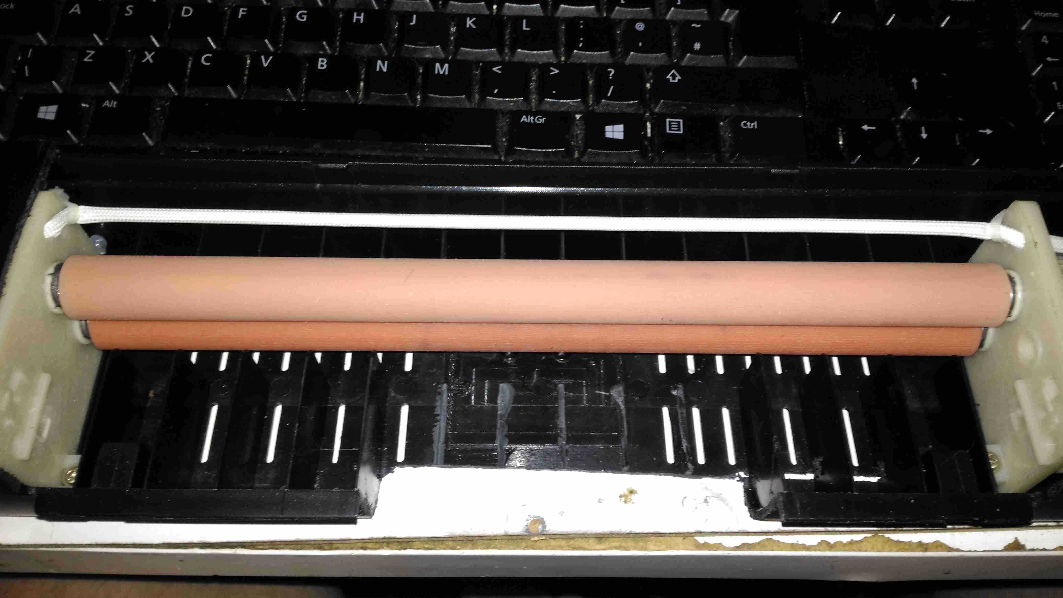
Once the board has been cleaned, one side of the backing film is removed from the gel with adhesive tape, and the dry film is placed on the board while still wet. This stops the film from sticking immediately to the clean copper, one edge is pressed down, and it’s then fed through a modified laminator:
Modified Laminator
I’ve cut away most of the plastic covering the hot rollers, as constant jamming was an issue with this cheapo unit. All the mains power is safely tucked away under some remaining plastic cover at the end. The board with it’s covering of dry film is fed into the laminator – the edge that was pressed down first. This allows the laminator to squeeze out any remaining water & air bubbles from between the two so no creases or blisters form.
After Lamination
Once the board has been run through the laminator about 6 times, (enough to get it very hot to the touch), the film is totally bonded to the copper. The top film is left in place to protect the UV sensitive layer during expsure.
Photomask
The exposure mask is laser printed onto OHP transparencies, in this case I’ve found I need to use two copies overlaid to get enough opacity in the black toner sections to block the UV light. Some touching up with a Sharpie is also easy to do if there are any weak spots in the toner coverage. This film is negative type – All the black areas will be unexposed and washed off in the developer tank. I also found I had to be fairly generous with track spacing, using too small lines just causes issues with the UV curing bits of film it isn’t supposed to.
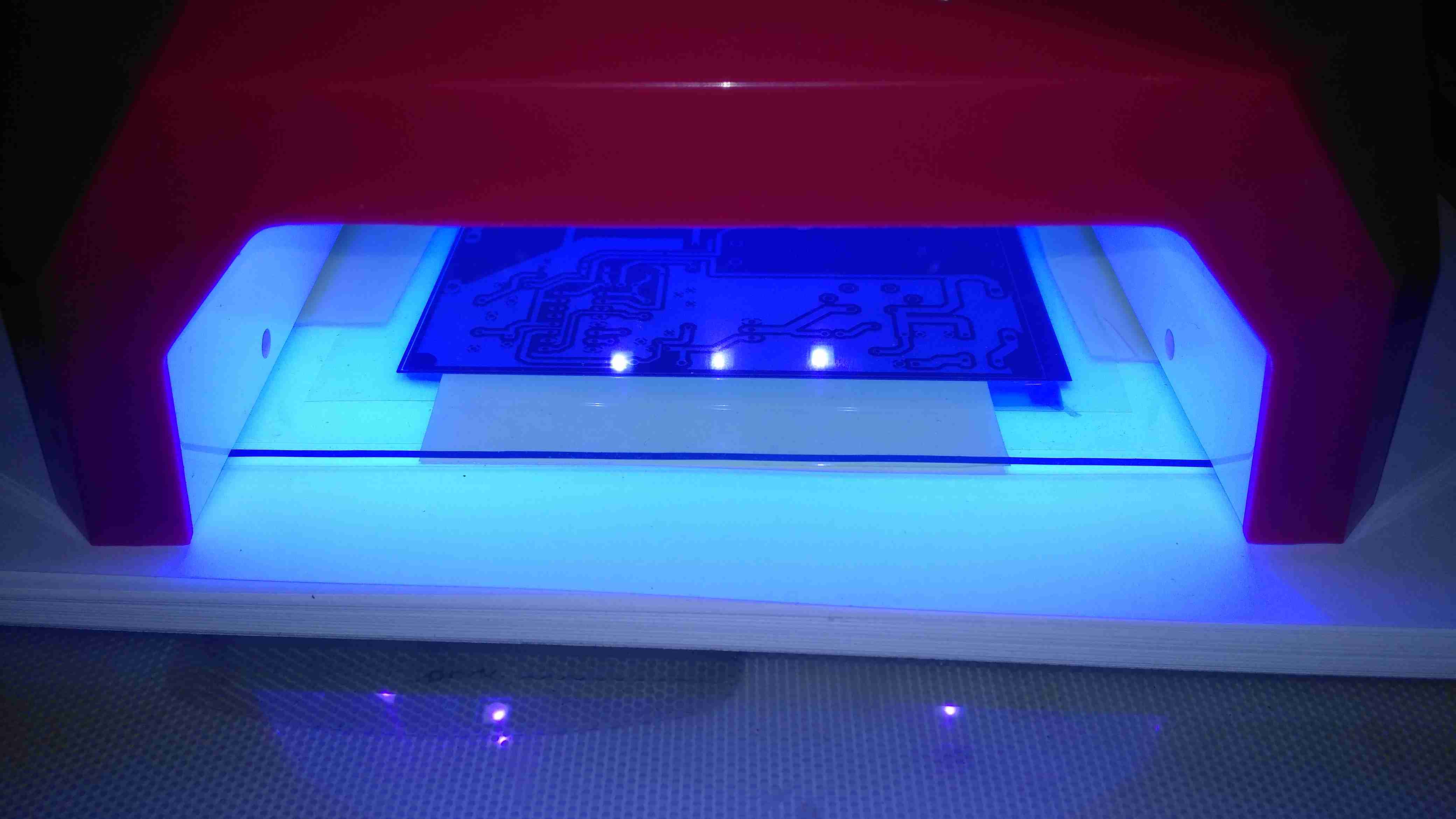
Exposing The PCB
The PCB is placed on a firm surface, the exposure mask lined up on top, and the whole thing covered with a sheet of standard glass to apply even pressure. The UV exposure lamp in this case is a cheap eBay UV nail curing unit, with 15 high power LEDs. (I’ll do a teardown on this when I get some time, it’s got some very odd LEDs in it). Exposing the board for 60 seconds is all the time needed.
After Exposure
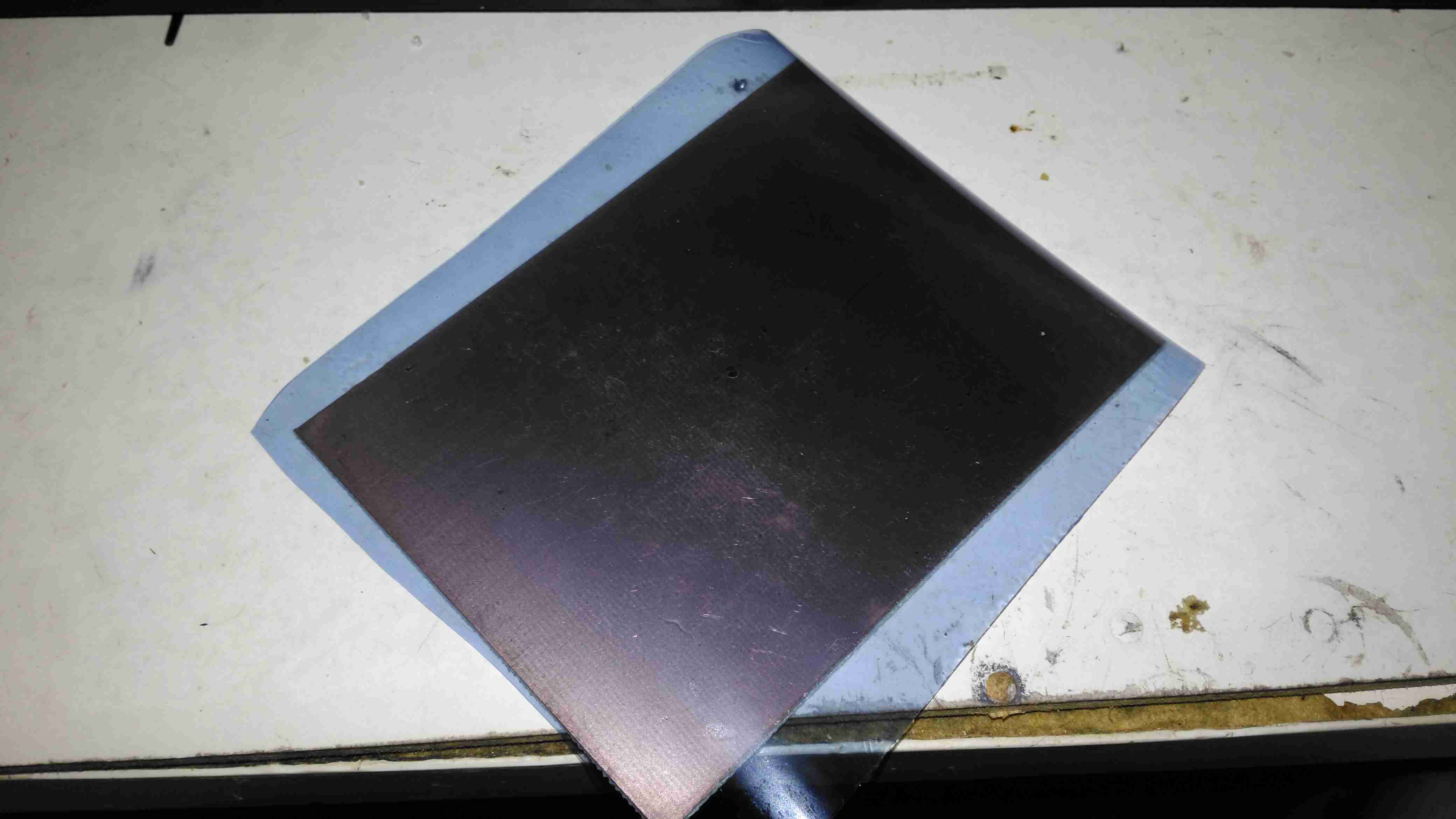
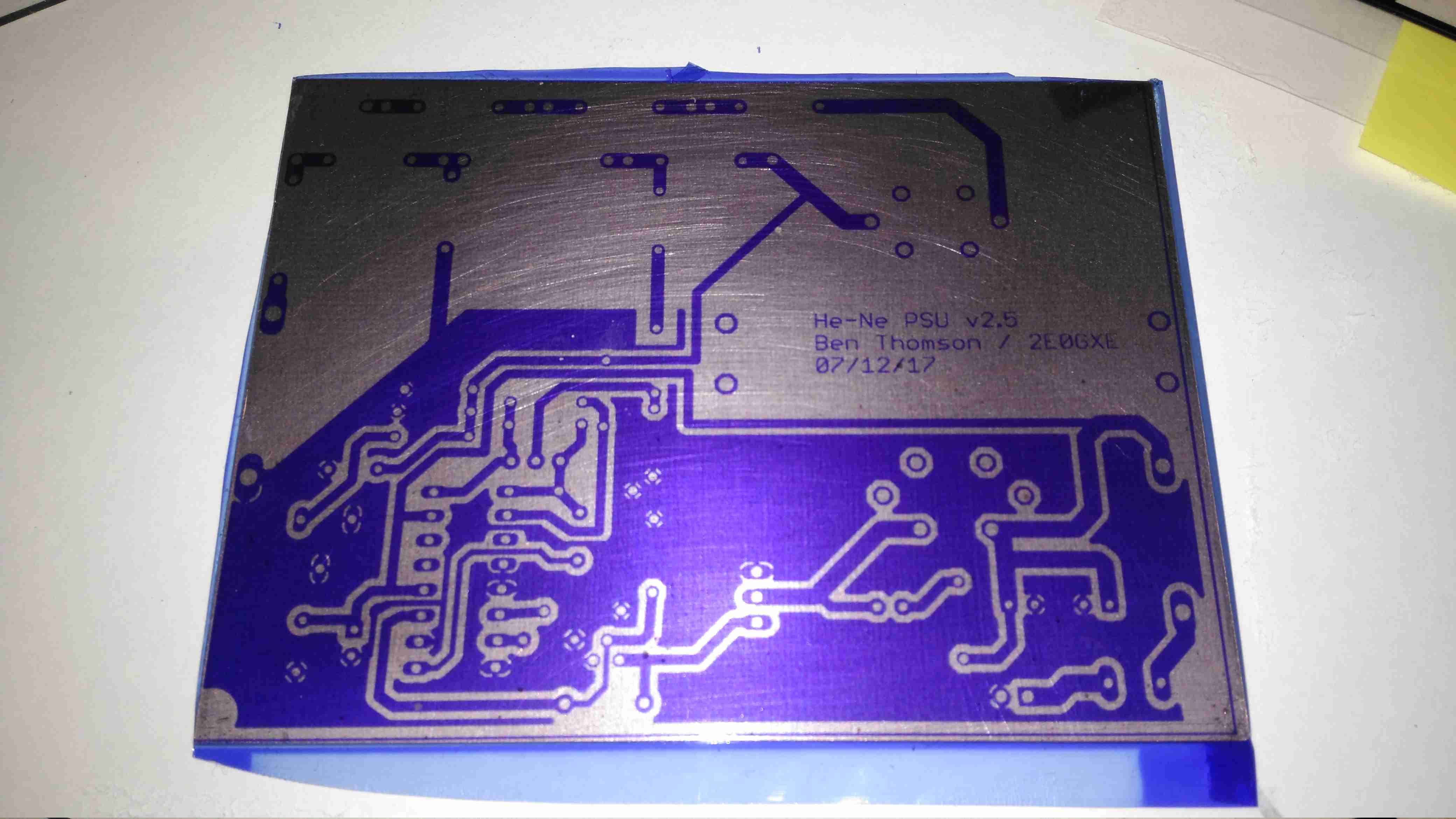
After the board is exposed, the areas that got hit with the UV light have turned purple – the resist has hardened in these areas. It’s bloody tough as well, I’ve scrubbed at it with some vigour and it doesn’t come off. Toner transfer was a bit naff in this respect, most of the time the toner came off so easily that the etchant lifted it off. After this step is done, the remaining protective film on the top can be removed.
After Developing
The film is developed in a solution of Sodium Carbonate (washing Soda). This is mildly alkaline and it dissolves off the unexposed resist.
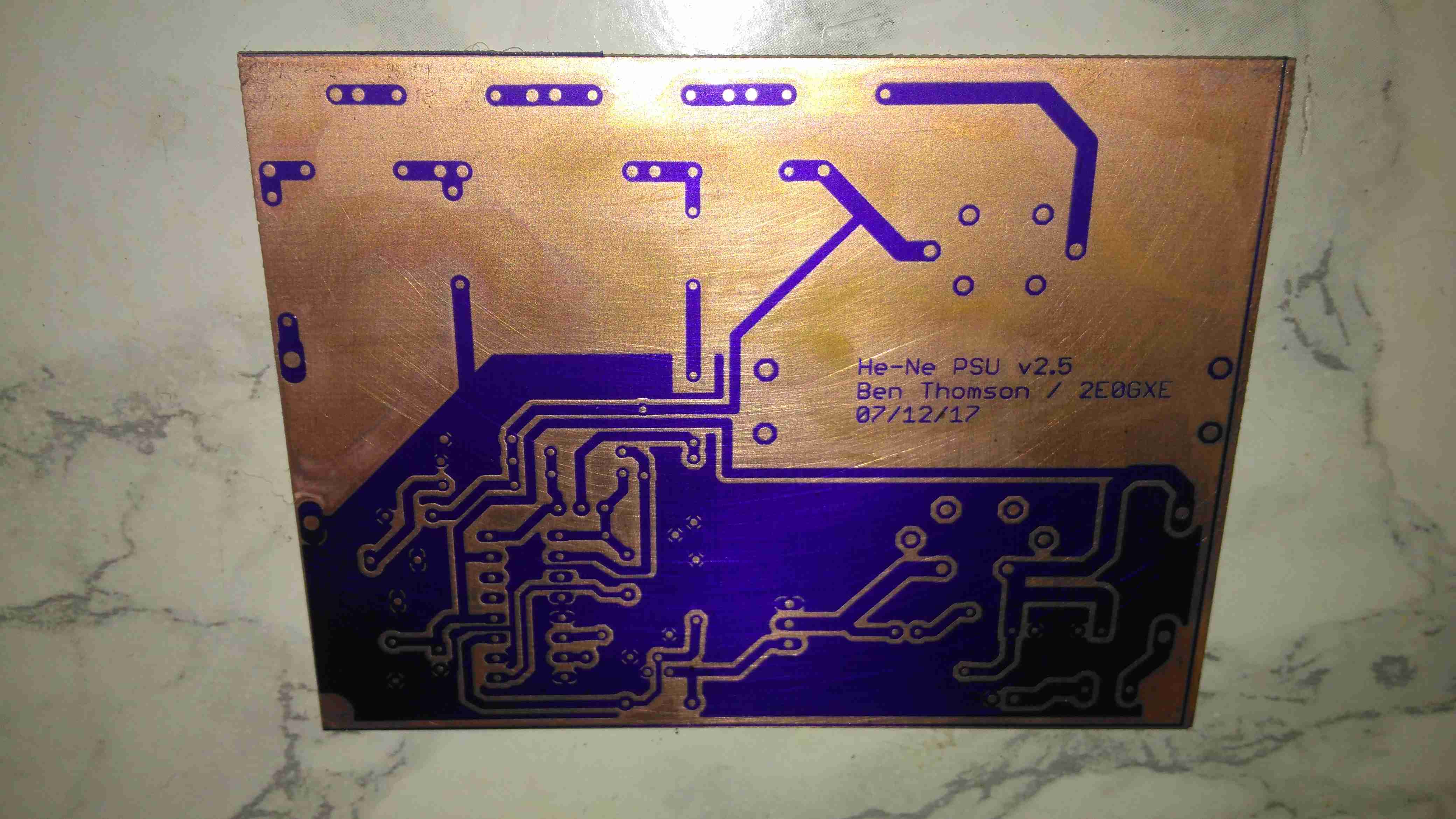
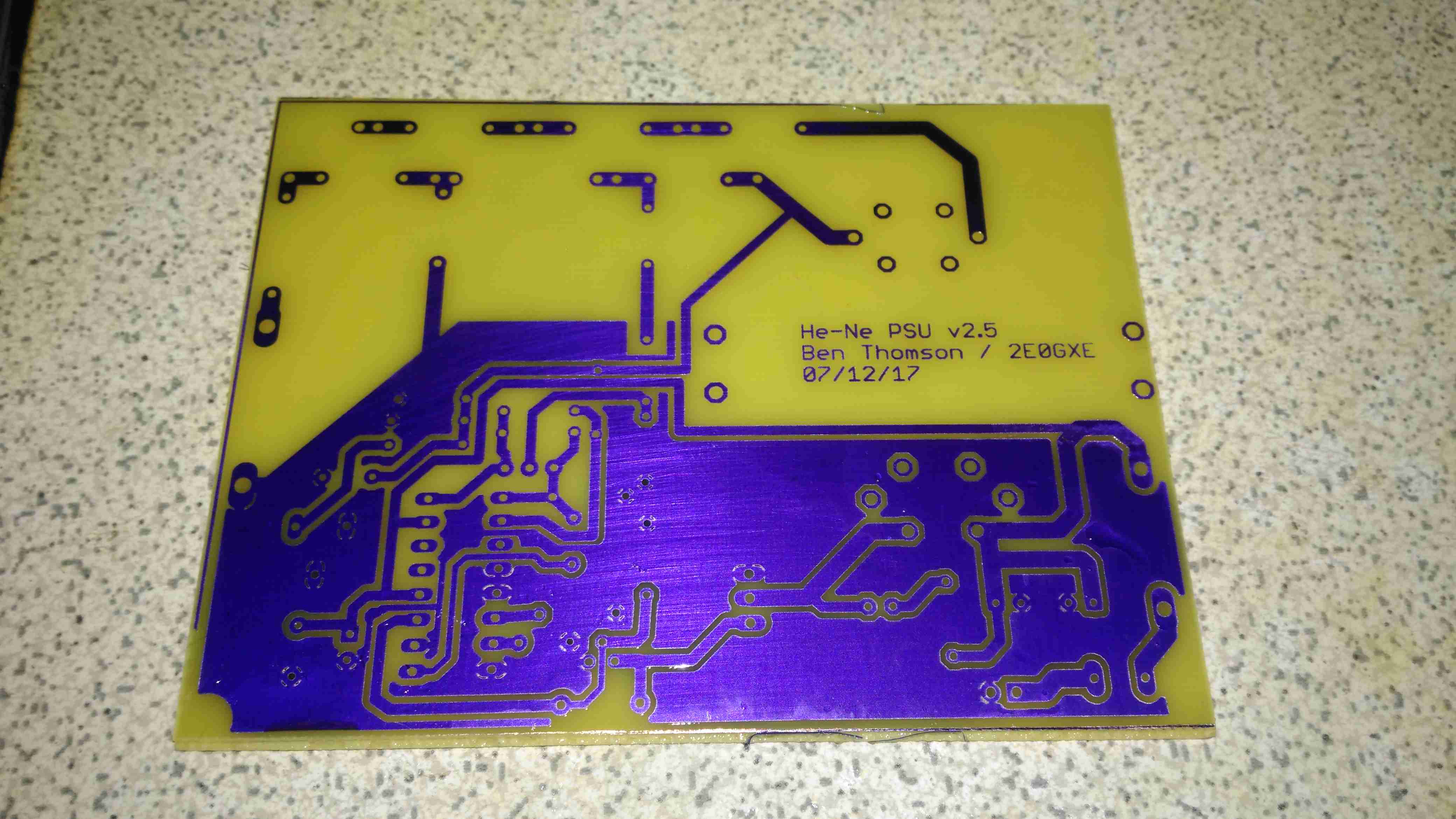
After Etching
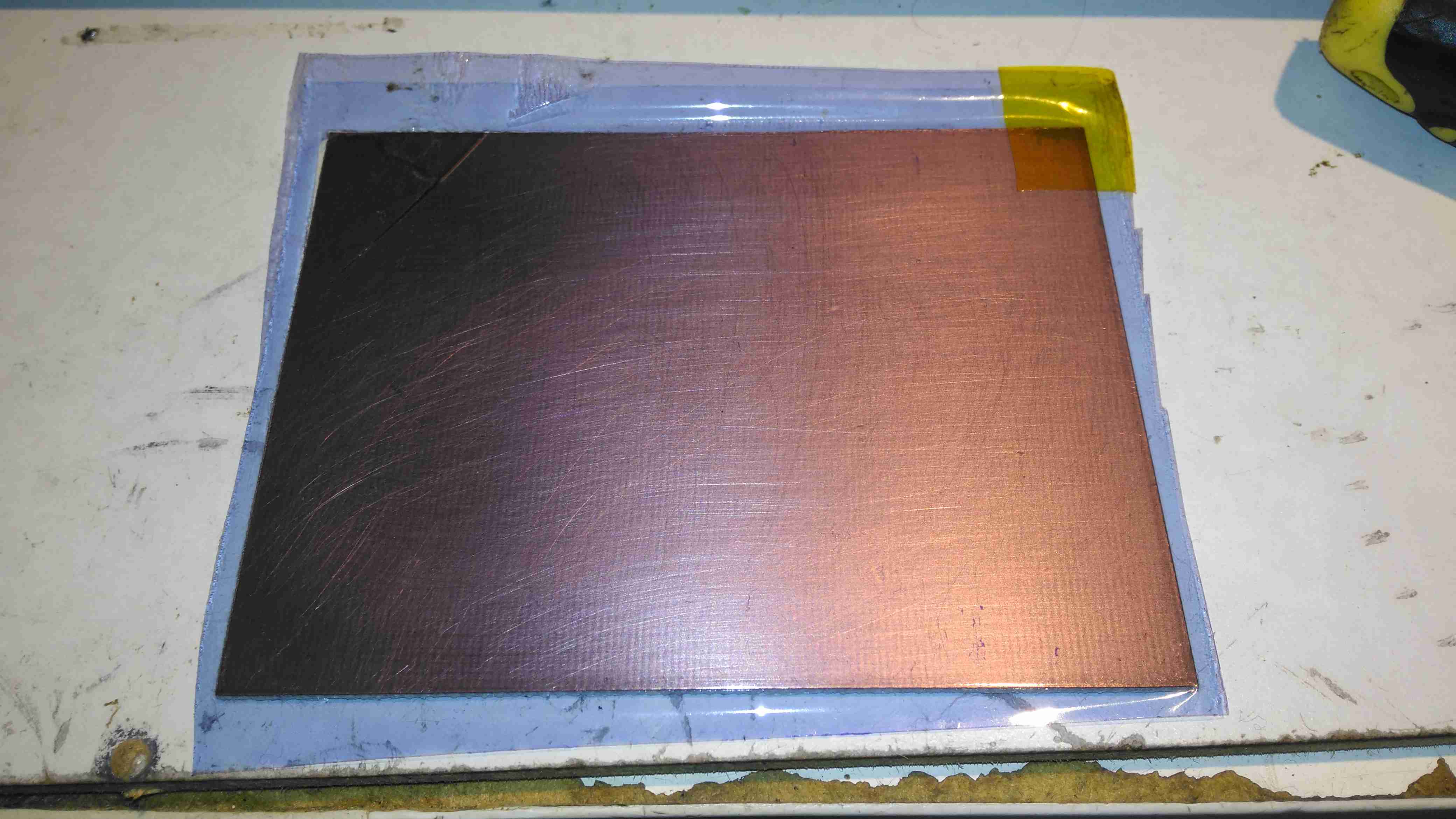
Now it’s into the etching tank for a couple of minutes, I’m still using Ferric Chloride to etch my boards, at about 60°C. Etching at room temperature is much too slow. Once this is done, the board is washed, and then dipped in the strip tank for a couple of minutes. This is a Sodium Hydroxide solution, and is very caustic, so gloves are required for this bit. Getting Ferric Chloride on skin is also a fairly bad idea, it stains everything orange, and it attacks pretty much every metal it comes into contact with, including Stainless Steel.
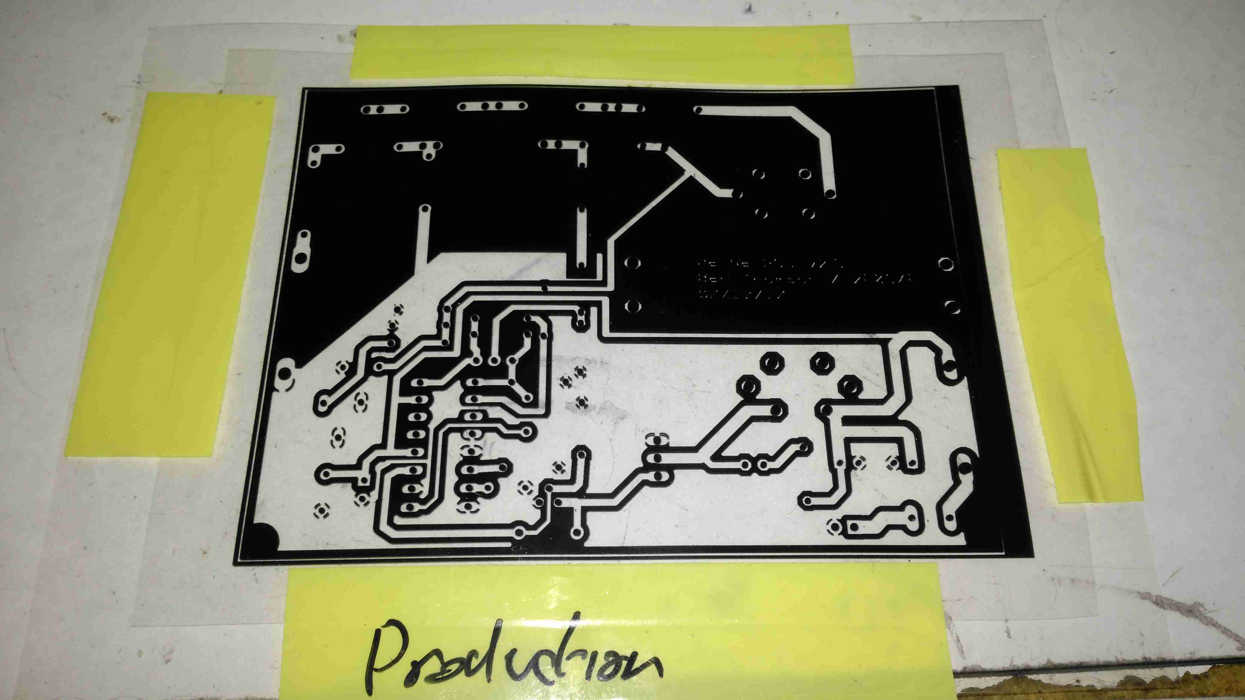
This method does require some more effort than the toner transfer method, but it’s much more reliable. If something goes wrong with the exposure, it’s very easy to strip the board completely & start again before etching. This saves PCB material and etchant. This is definitely more suited to small-scale production as well, since the photomask can be reused, there’s much less waste at the end. The etched lines are sharper, much better defined & even with some more chemicals involved, it’s a pretty clean process. All apart from the Ferric Chloride can be disposed of down the sink after use, since the developer & stripper are just alkaline solutions.
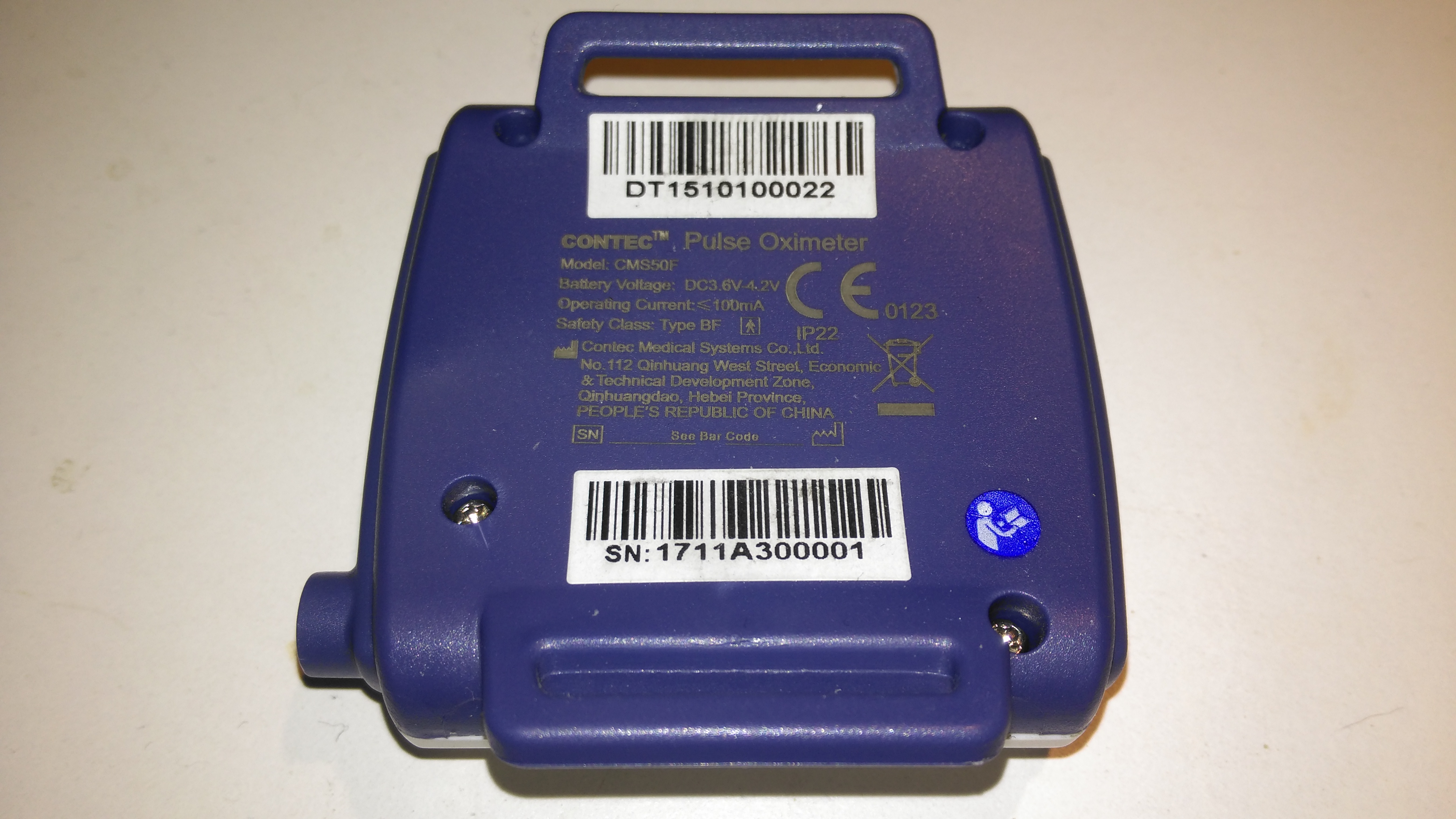
The rear has the specifications, laser-marked into the plastic. The serial numbers are just sticky labels though, and will come off easily with use.
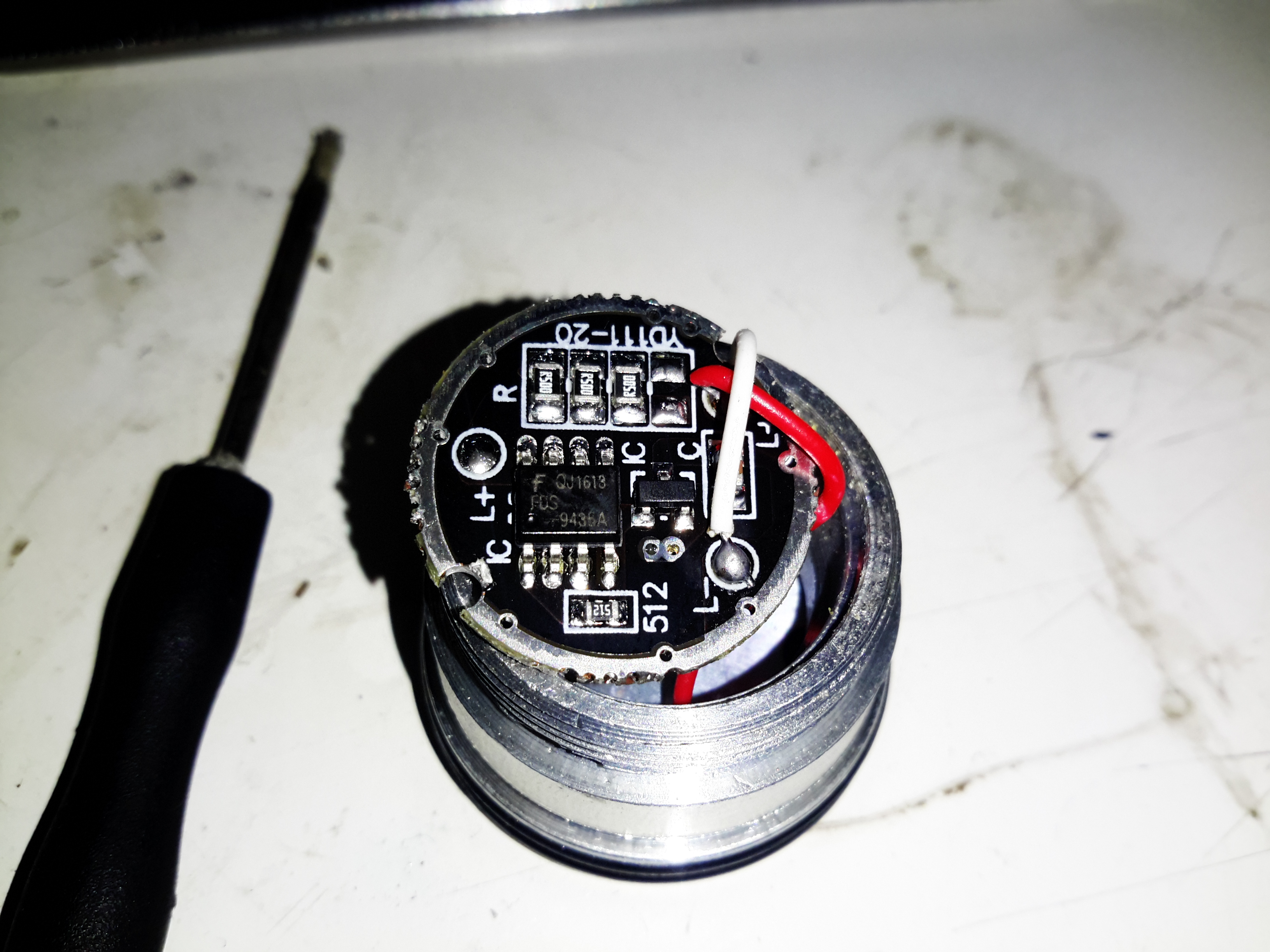
Contec CMS-50F
This is the Contec CMS-50F wrist-mounted pulse oximeter unit, which has the capability to record data continuously to onboard memory, to be read out at a later time via a USB-Serial link. There is software supplied with the unit for this purpose, although it suffers from the usual Chinese quality problems. The hardware of this unit is rather well made, the firmware has some niggles but is otherwise fully functional, however the PC software looks completely rushed, is of low quality & just has enough functionality to kind-of pass as usable.
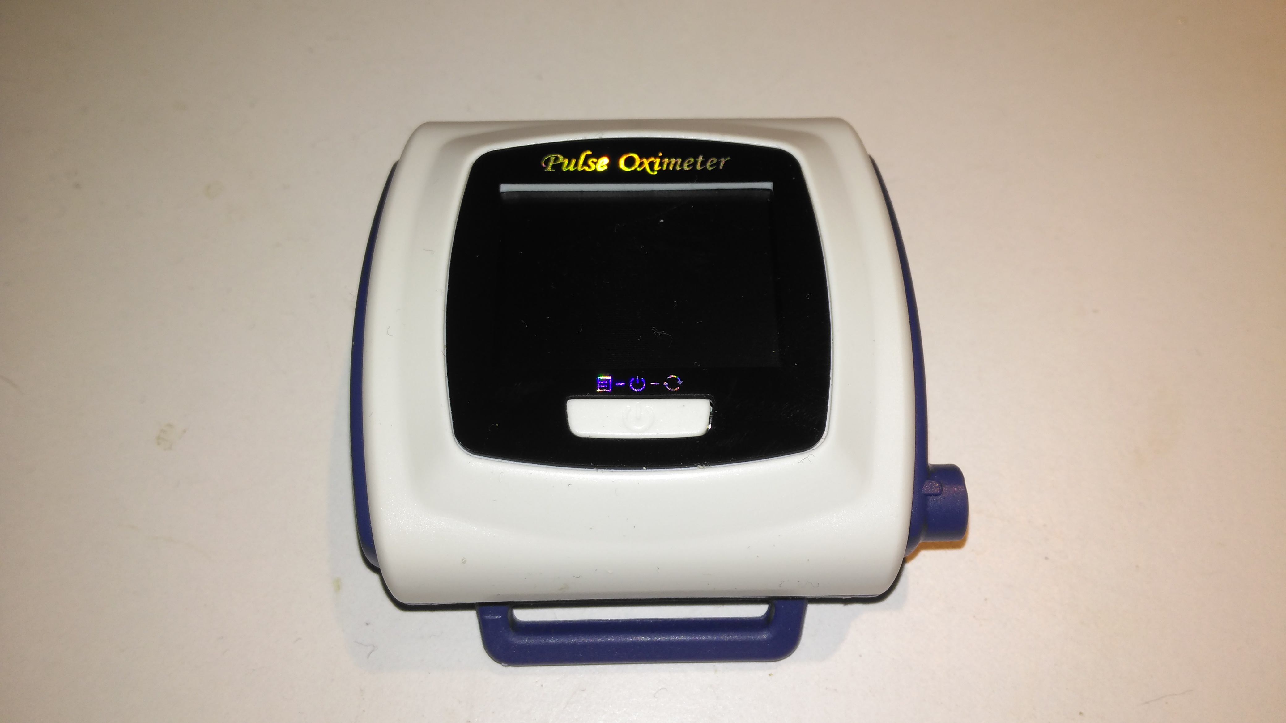
Top Cover Removed
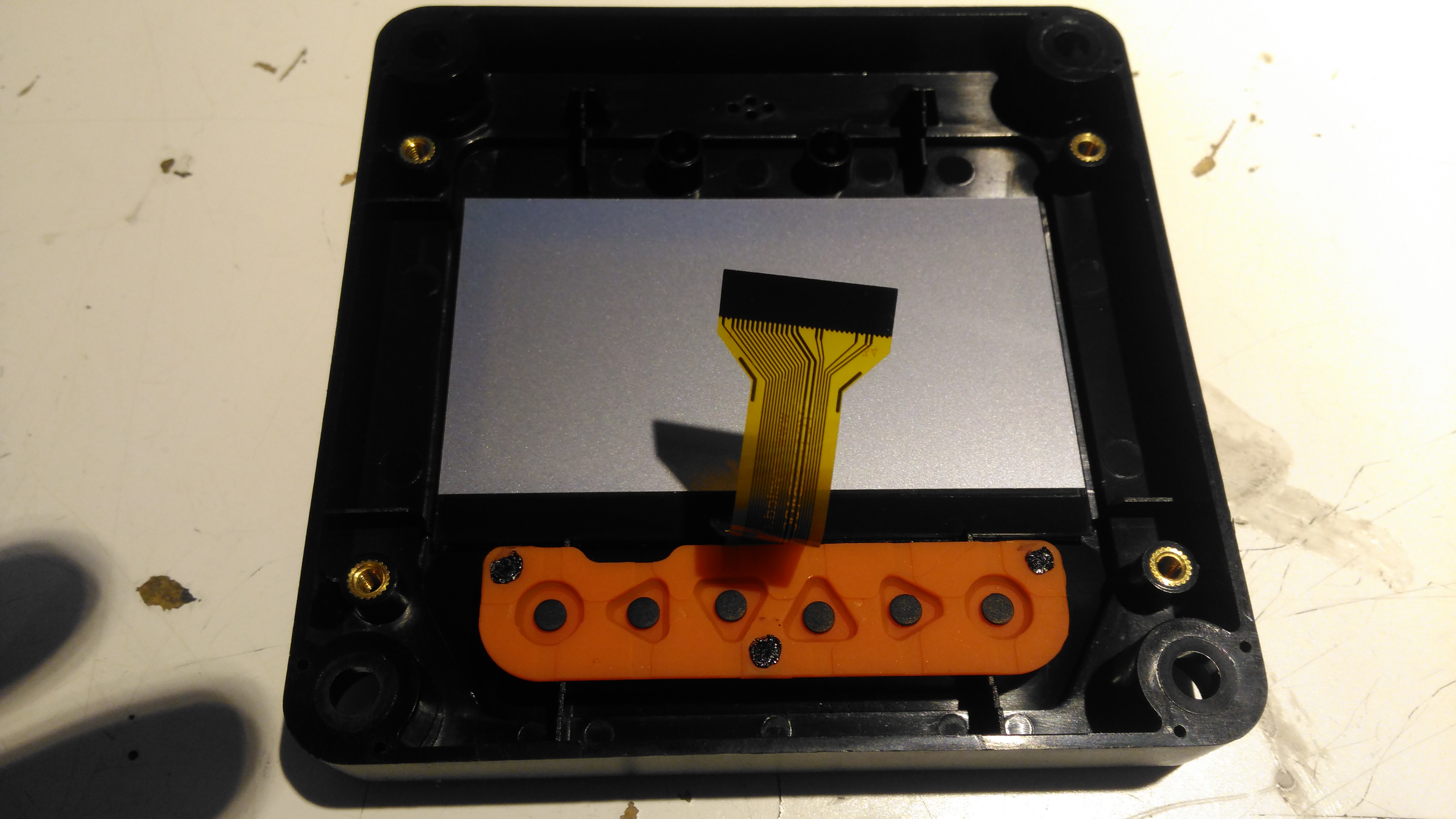
A total of 4 screws hold the casing together, once these are removed the top comes off. The large colour OLED display covers nearly all of the board here. The single button below is the user interface. The connection to the probe is made via the Lemo-style connector on the lower right.
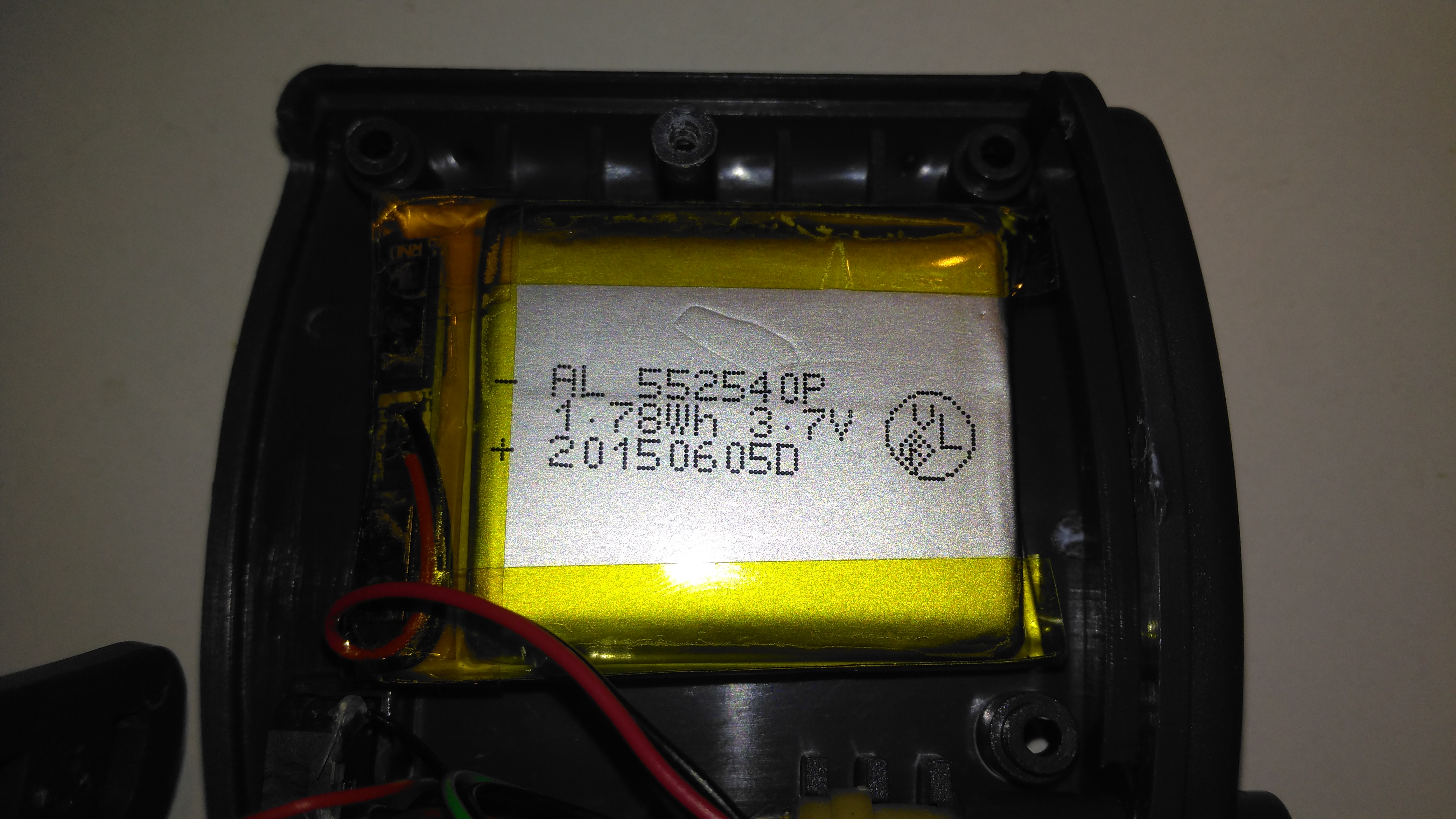
Lithium Cell
Power is provided by a relatively large lithium-ion cell, rated at 1.78Wh.
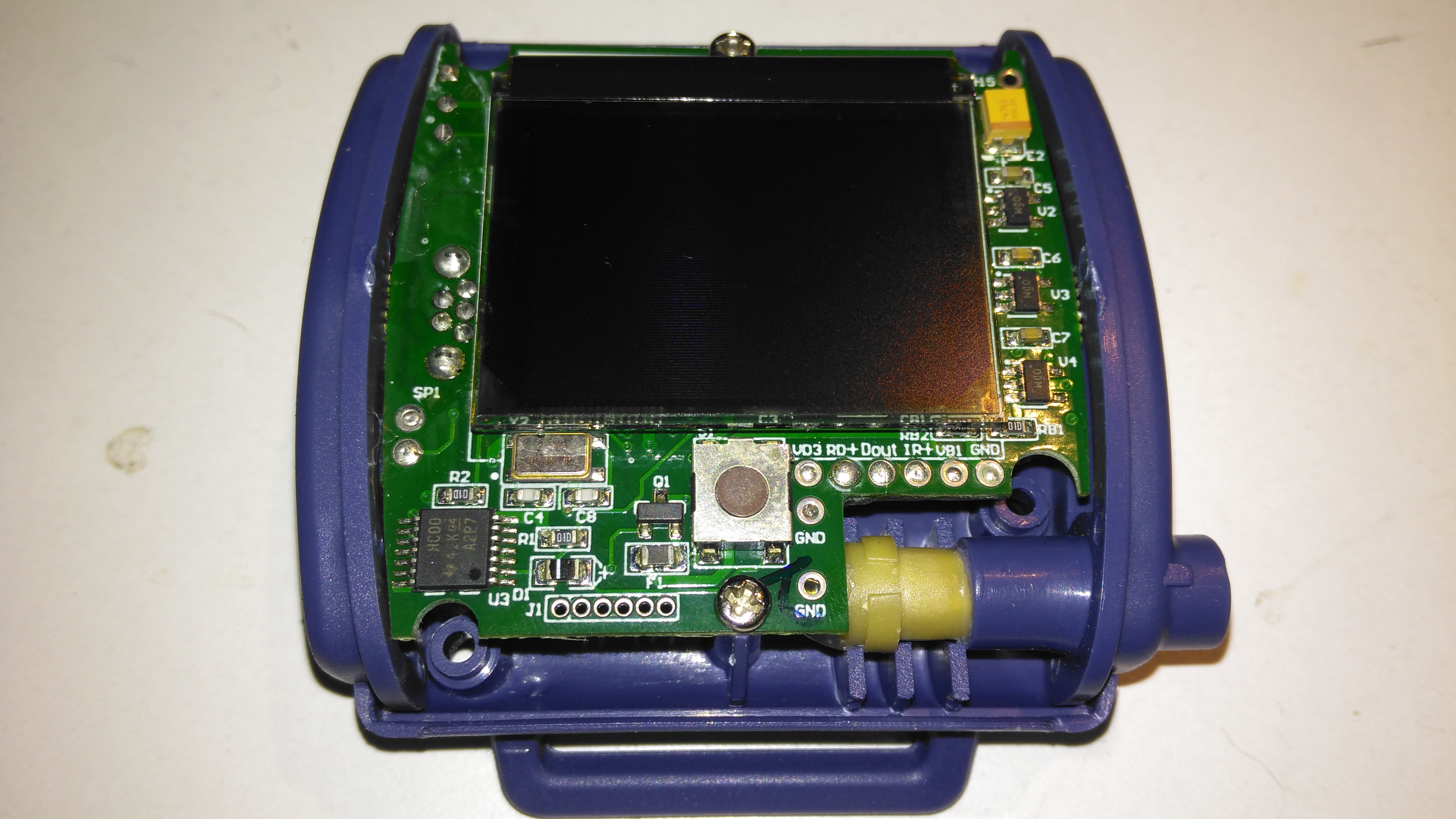
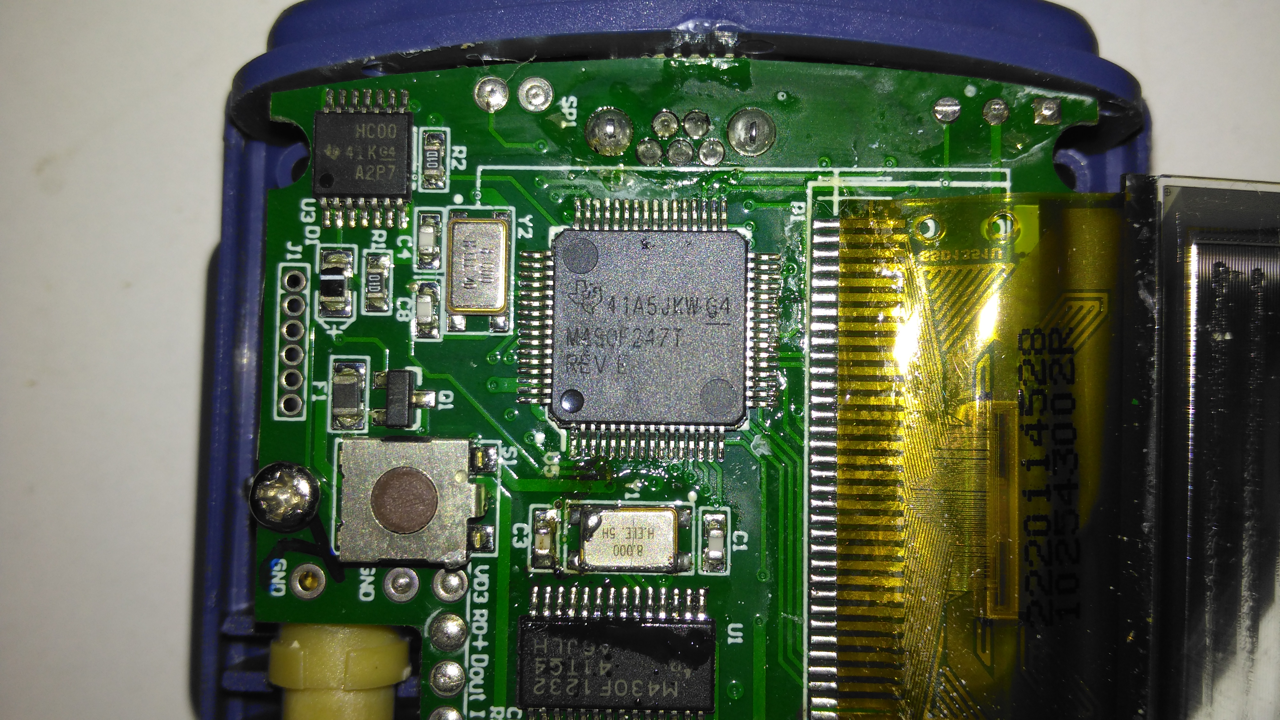
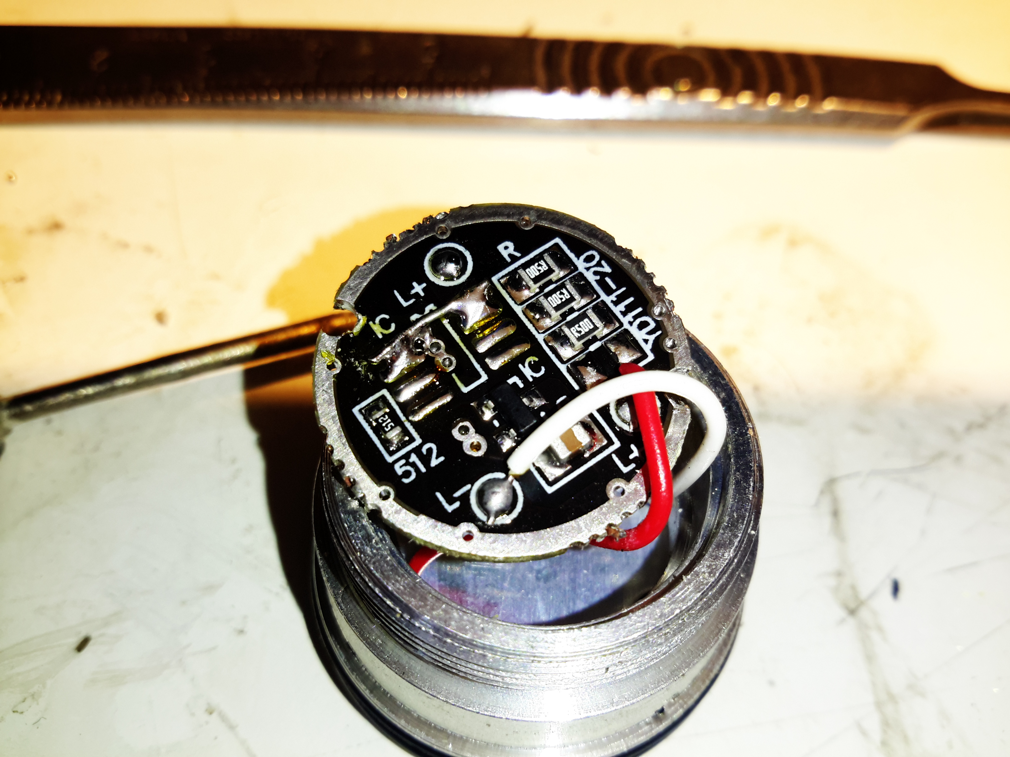
Main Processor
All the heavy lifting work of the LCD, serial comms, etc are handled by this large Texas Instruments microcontroller, a MSP430F247. The clock crystal is just to the left, with the programming pins. I’m not sure of the purpose of the small IC in the top left corner, I couldn’t find any reference to the markings.
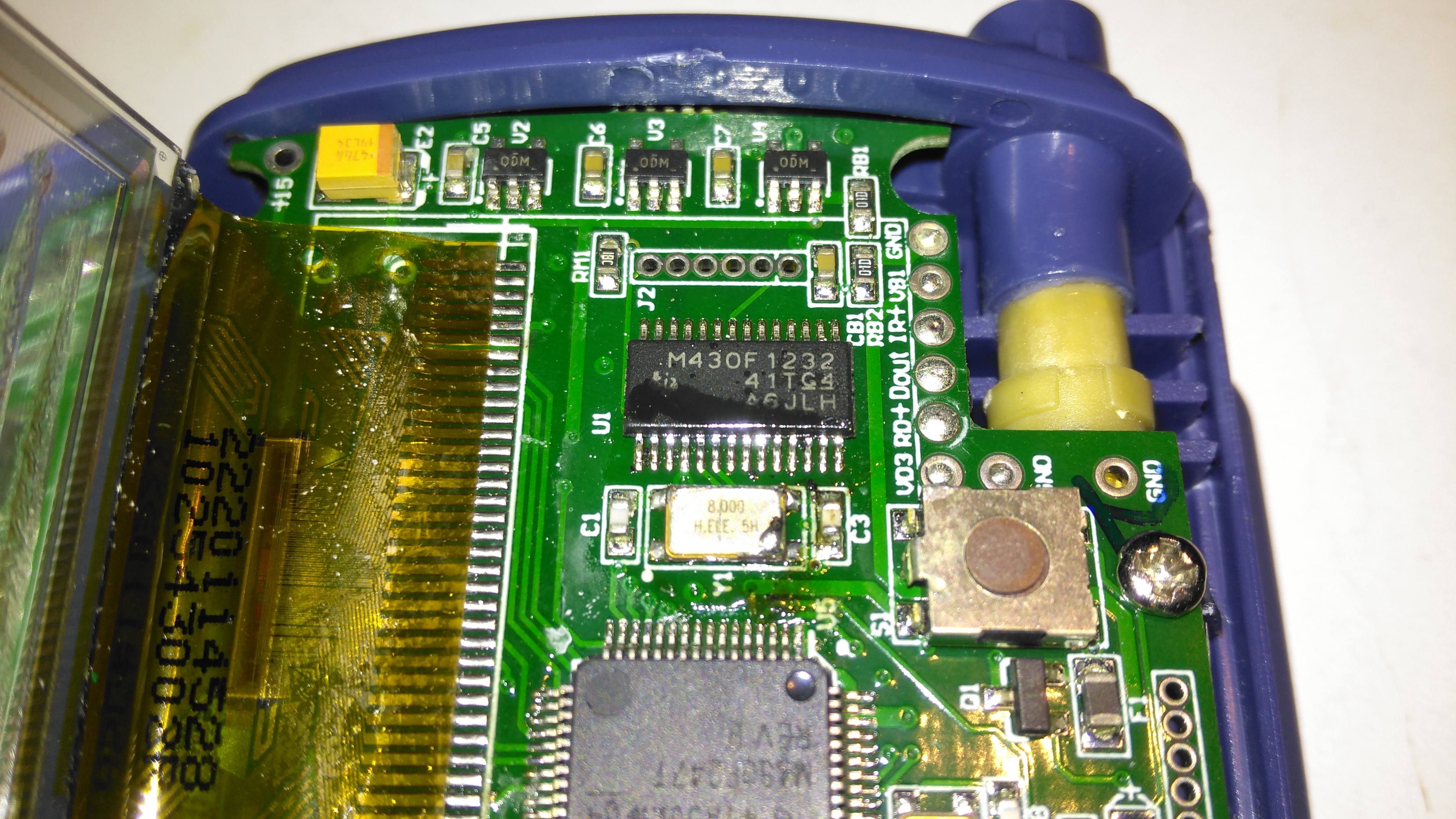
Aux Processor
The actual pulse oximetry sensor readings seem to be dealth with by a secondary microcontroller, a Texas Instruments M430F1232 Mixed-Signal micro. This has it’s own clock crystal just underneath. The connections to the probe socket are to the right of this µC, while the programming bus is broken out to vias just above. The final devices on this side of the board are 3 linear regulators, supplying the rails to run all the logic in this device.
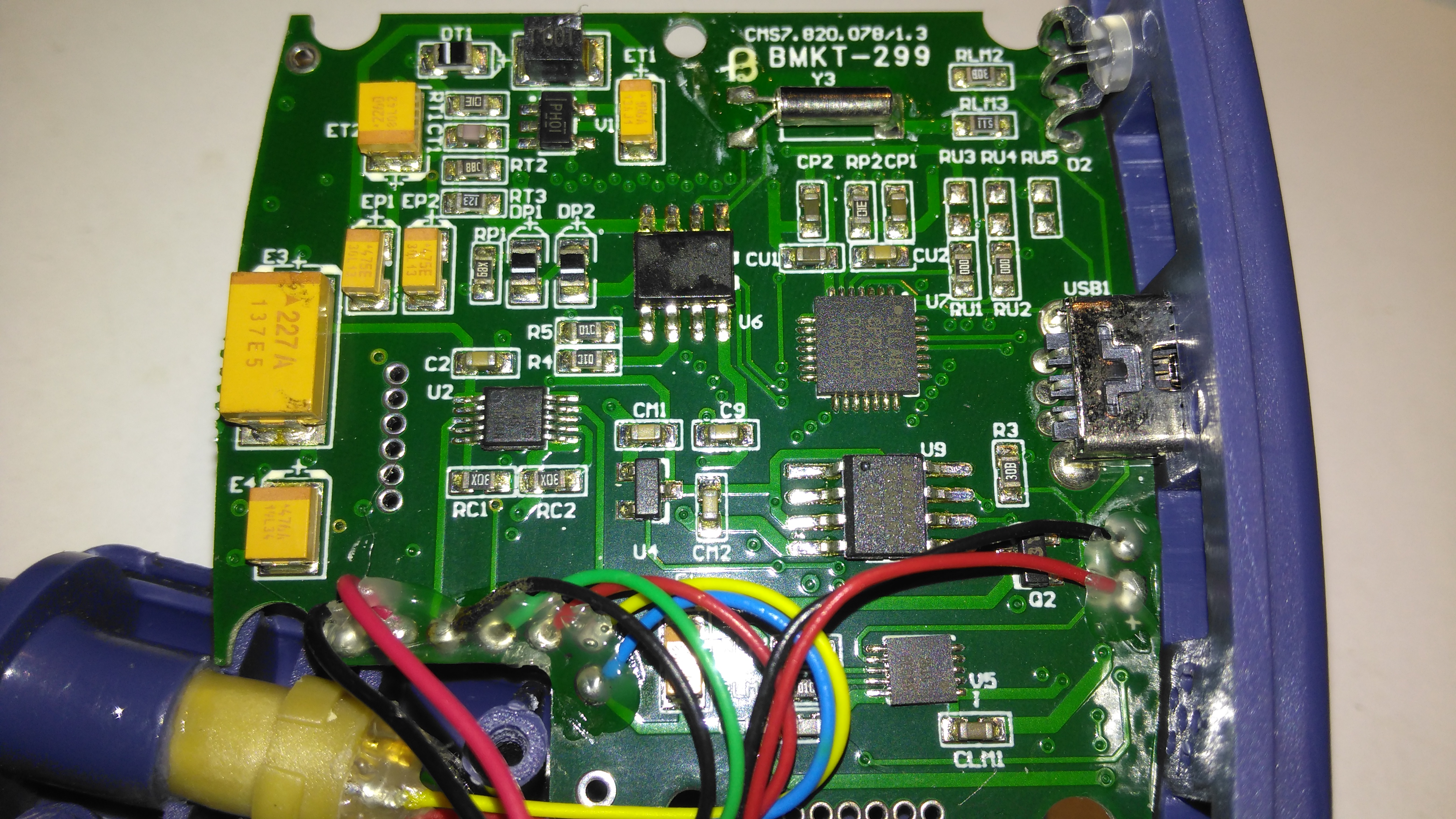
Main PCB Rear
The rear of the PCB has the SiLabs CL2102 USB-Serial interface IC, the large Winbond 25X40CLNIG 512KByte SPI flash for recording oximetry data, and some of the power support components. The RTC crystal is also located here at the top of the board. Up in the top left corner is a Texas Instruments TPS61041 Boost converter, with it’s associated components. This is probably supplying the main voltage for the OLED display module.
Some time ago I posted about an ancient piece of EDA software called Stripboard Magic, which was made by a small British company by the name of Ambyr. I have been hosting copies of this now long-dead software for some time, as it still seems to be in popular demand long after being abandoned by it’s creators. I have been contacted by a reader about the existence of Service Packs for this application, which neither of us have been able to locate.
From what I have been able to gather, Ambyr ceased trading around 1999-2000, after having sold the rights to distribute Stripboard Magic to Maplin Electronics. What I’m not certain of is the timeframe of these service packs appearing, or where they could originally be found, the Ambyr website apparently vanished about 6 months after Stripboard Magic was originally released, but they were presumably intended to make the application easier to use & less buggy.
Unfortunately the timeframe for the company’s existence was before the Wayback Machine started archiving the internet, and the only record they have of Ambyr is a domain holding page dating back to 2000.
If there are any readers who have copies of these service packs, or some information on where they can be found, or indeed any more information in general about this seemingly short-lived company, please drop a comment or E-Mail me directly through the Contact Page. Inquiring minds need to know 😉
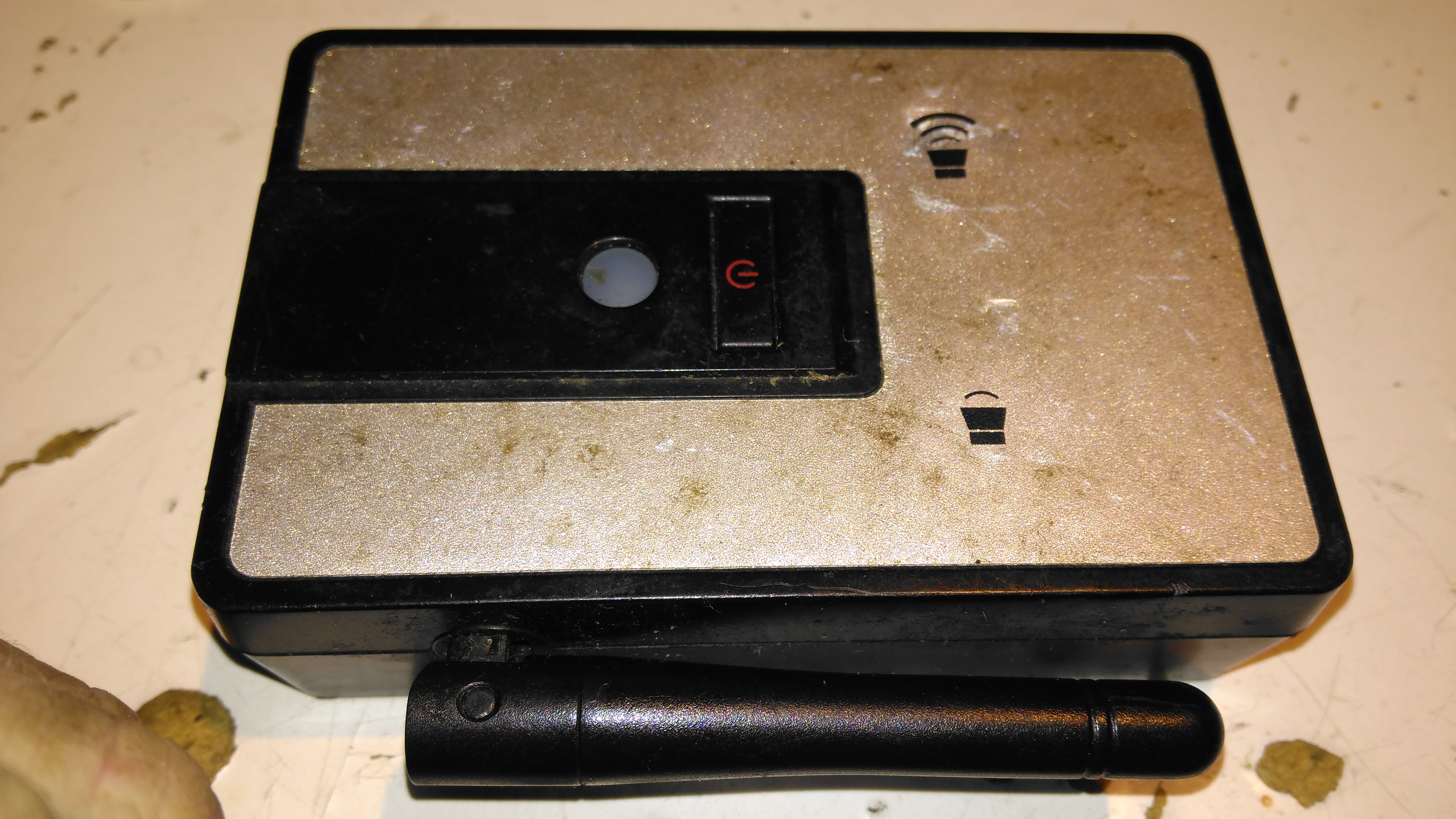
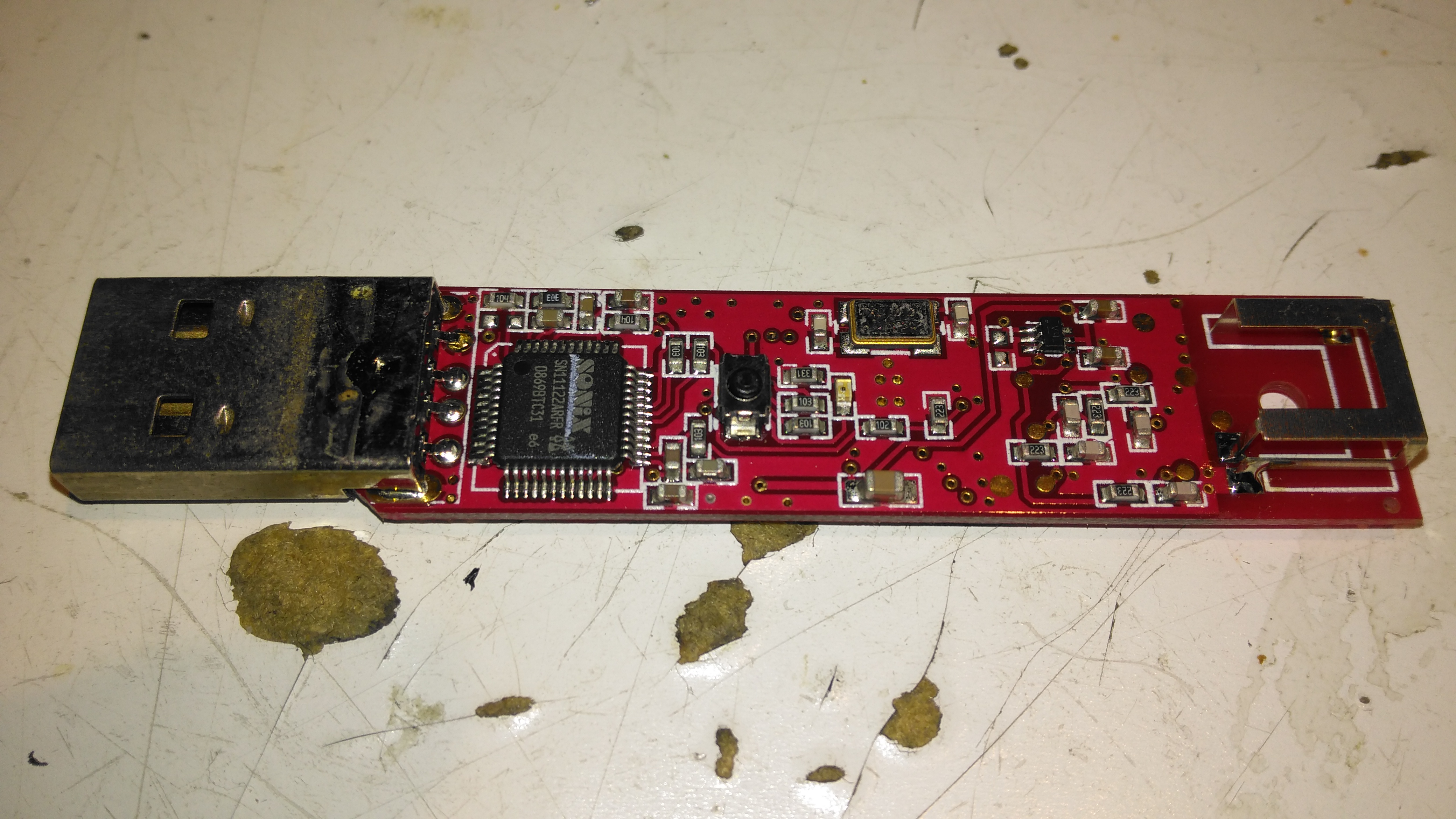
This is a pair of modules that Maplin was selling some time back, to send stereo audio over a 2.4GHz radio link. The transmitter identifies as a USB sound card, I’ve personally used these units to transmit audio about 60ft. The transmitter, above, has a single button for pairing with the receiver below.
Receiver
The receiver unit has a large external antenna, a link status LED & volume buttons, these directly control the volume level on the host PC via the sound card drivers.
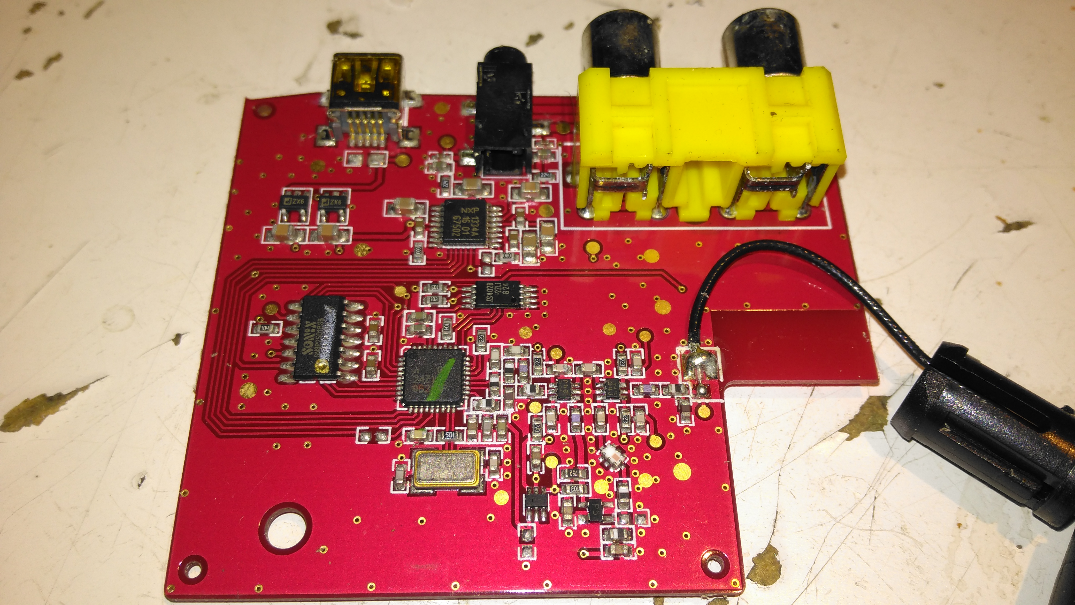
Receiver PCB Top
Popping the case open on the receiver reveals a large PCB, holding the chipset, along with the audio output jacks & Mini-USB power input. The antenna Coax is soldered to the PCB.
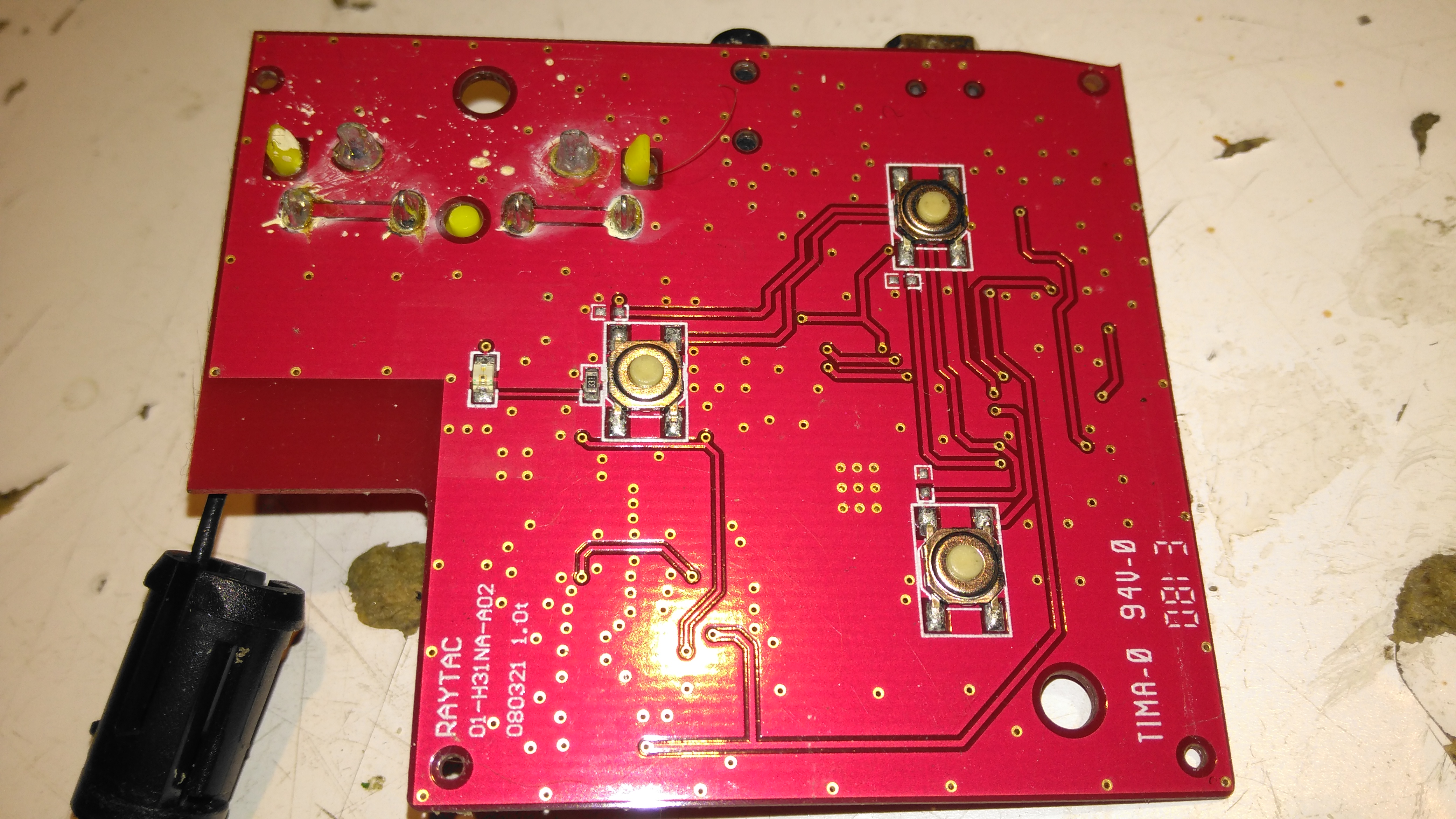
Receiver PCB Bottom
The top of the board has the control buttons, and the status LED.
Receiver Chipset
The chipset used here is a Nordic Semiconductor nRF20Z01 2.4GHz Stereo Audio Streamer, there’s a small microcontroller which does all the register magic on the RF transceiver. The RF chain is at the top of the photo, audio outputs on the top left, and the micro USB power input & voltage regulators at bottom left.
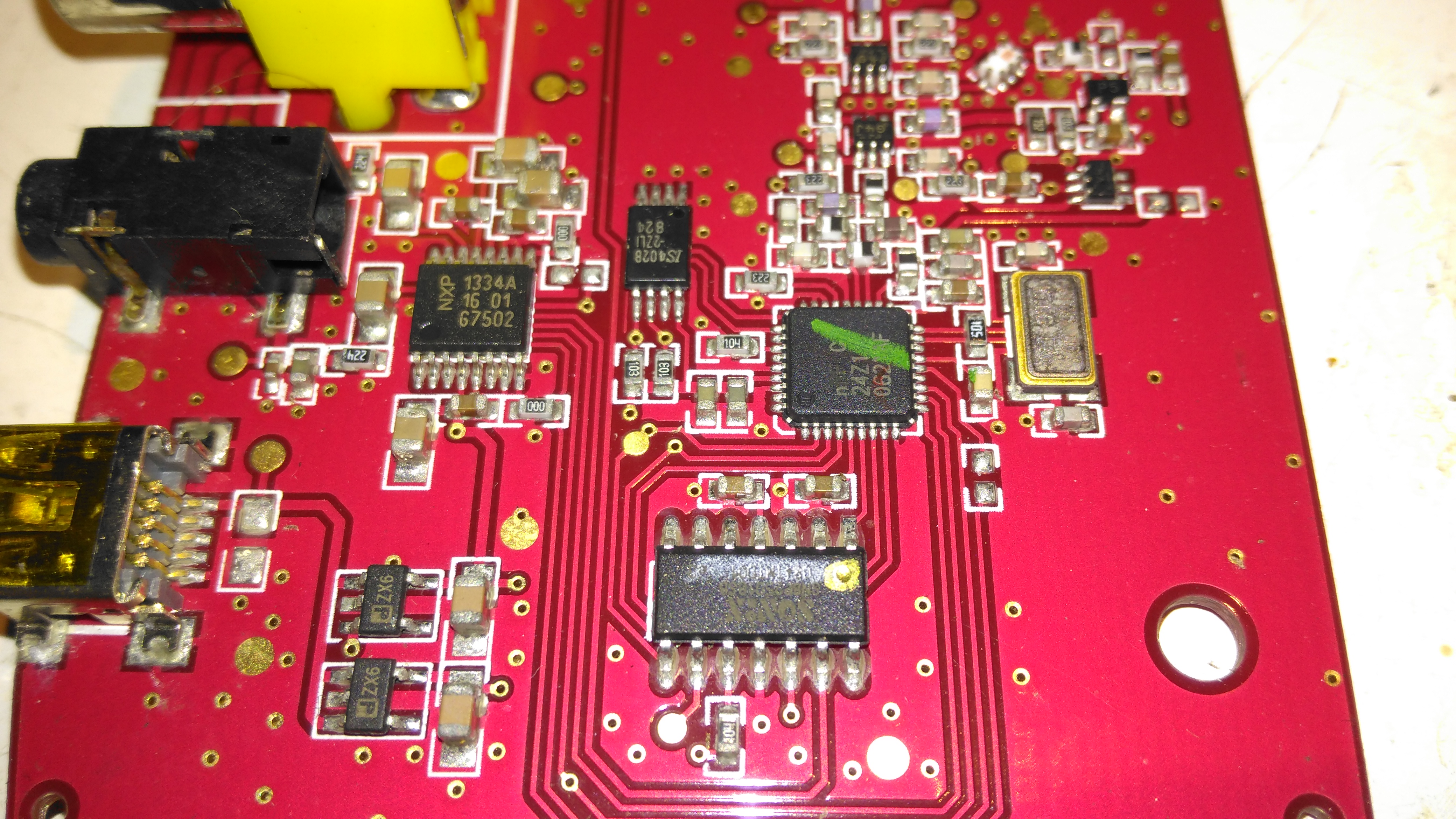
Transmitter PCB Top
The transmitter PCB has a Sonix USB Audio Codec, to interface with the host PC. This is then fed into another Nordic Semi part on the opposite side of the board:
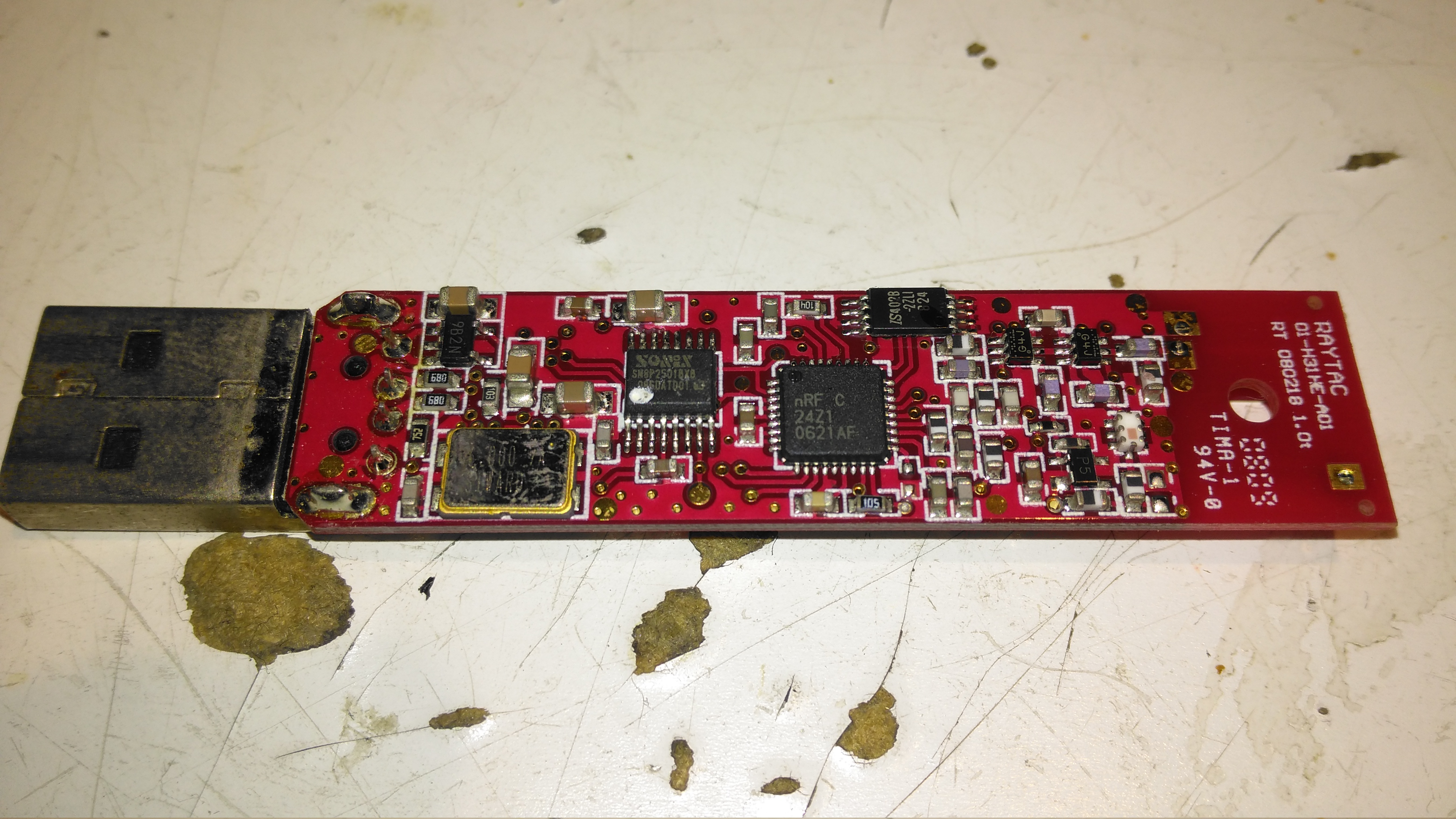
Transmitter PCB Bottom
The bottom of the transmitter has the RF section, and another small control microcontroller.
The housing of the contaminated motor was left to soak in diesel for a few hours to loosen the grok, this has come very clean. I couldn’t have used a stronger solvent here – the magnets are glued in place in the steel housing, I certainly didn’t want them coming loose!
Brushboxes
Next into the diesel bath are the motor end bells with the brushgear. Attack with a stiff brush cleaned these up very well, some cotton buds served to clean out the brass brush holders.
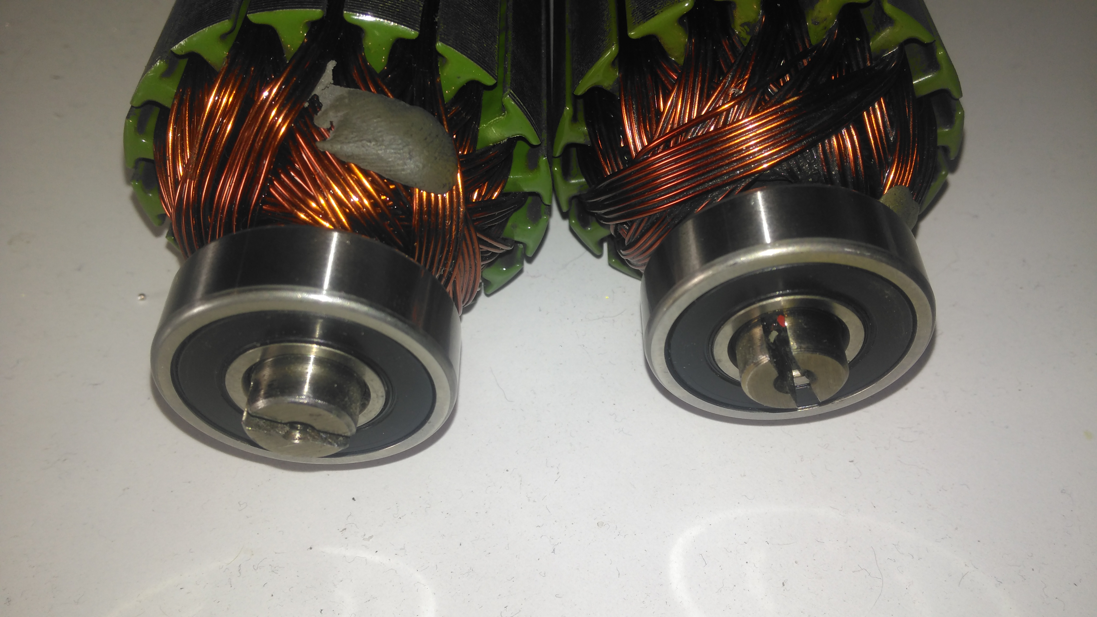
Armatures After Skimming
Here are both armatures, having had their commutators resurfaced. I’ve completely removed all traces of the wear caused by the contamination, luckly the commutator bars are very heavy on these motors so can take quite a bit of wear before there’s not enough left to skim. I’ve not yet pulled off the old bearings, but they are all going to be replaced with new SKF bearings, as they’ve been contaminated with grok over the years of use. I’m also going to uprate the front motor bearings to rubber sealed instead of metal shielded, to help keep lubricant out of the motors if the gearbox seals ever fail again.
Gearbox
The gearboxes have been cleaned out with some elbow grease, assisted by a long soak in petrol, I’ve refilled them here with engine oil as temporary lube & to flush out the last remains of the old grease & solvent. The worm wheel in these boxes is bronze – so a GL4 gear oil will be required. (Some Extreme Pressure additive packs contain sulphur, and will readily attack copper alloys, such as brass & bronze).
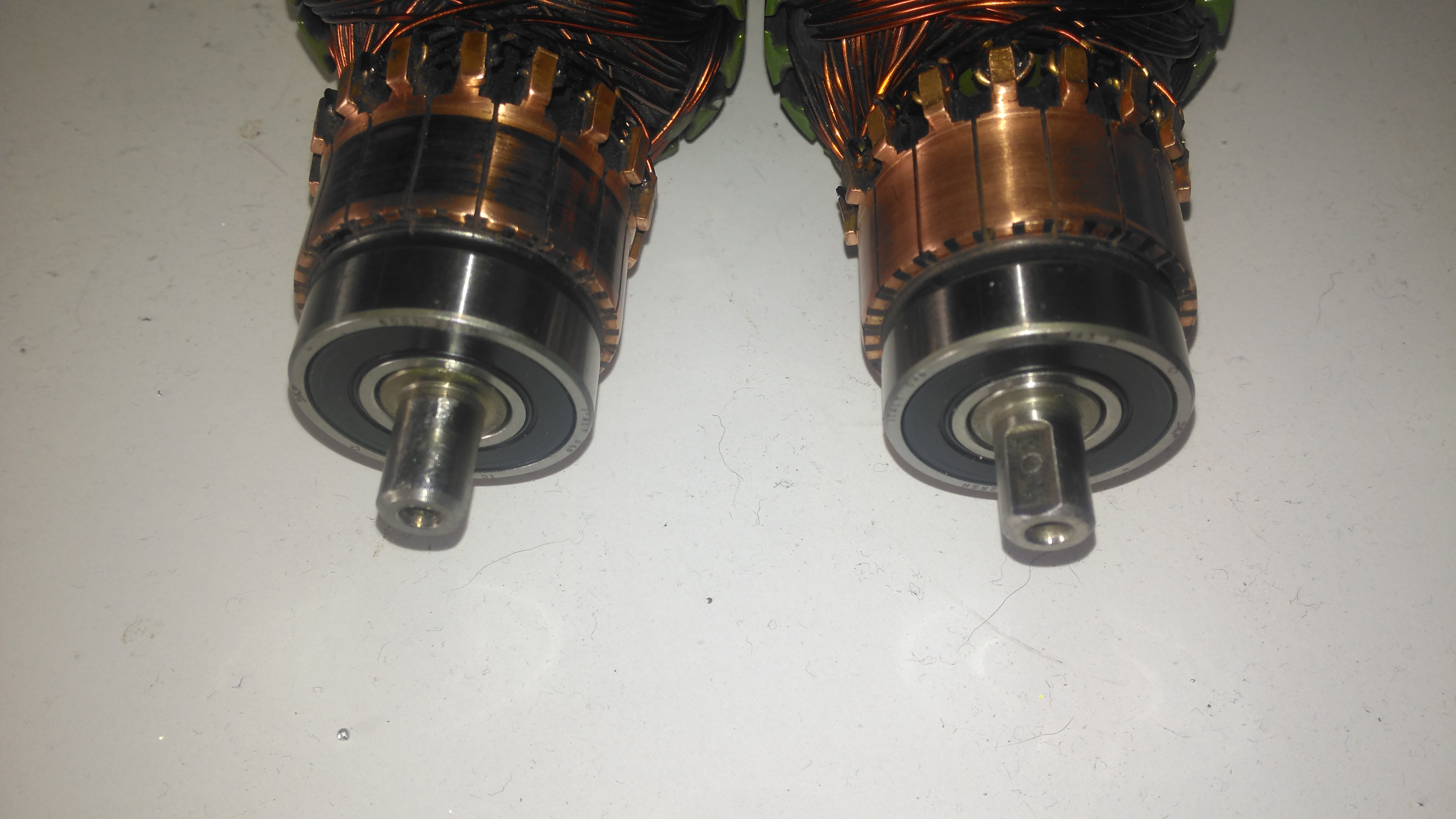
Commutator End Bearings
Here’s the armatures, after the new SKF sealed bearings have been fitted to the commutator end, above, and the drive end, below. These will cause some extra drag on the armatures, and slightly higher power consumption as a result, but keeping the crap out of the motors is slightly more important.
Drive End BearingsFresh Commutator Skim
The commutators have been lightly skimmed with abrasive cloth, and finished with 1500 grit emery. The armature on the right has been run for a short time to see how the new brushes are bedding in.
Old Seal Removed
Finally, the old oil seals are pulled from the gearboxes. The worm gear bearing on the inside is actually a sealed version, with the external oil seal providing some extra sealing. I haven’t changed the gearbox bearings, as they seem to be in good order, this might get done at some point in the future.
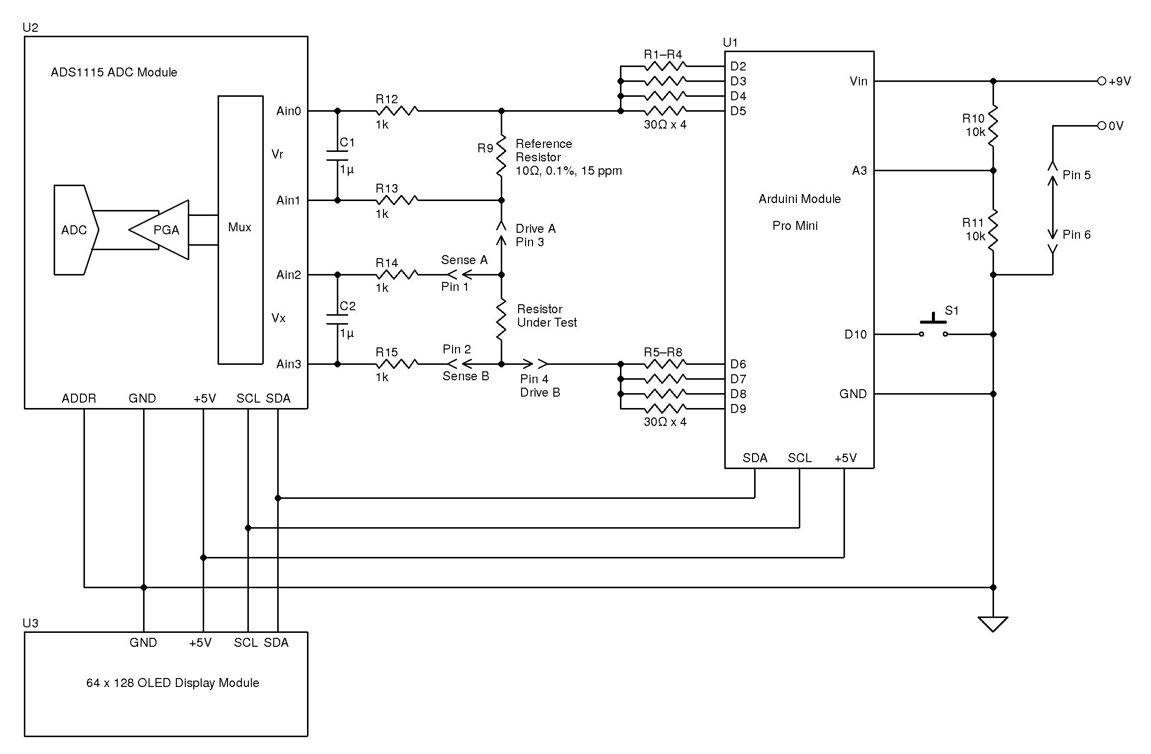
During the rebuild of the wheelchair motors for the support trolley, I found myself needing an accurate milliohm meter to test the armature windings with. Commercial instruments like these are expensive, but some Google searching found a milliohm meter project based around the Arduino from Circuit Cellar.
Circuit Diagram
Here’s the original author’s circuit diagram, paralleling nearly all of the Arduino’s digital output pins together to source/sink the test current, an ADS1115 ADC to take more accurate readings, with the results displayed on a jellybean 128×64 OLED module. The most expensive part here is the 10Ω 0.1% 15ppm reference resistor, R9.
I decided to make some small adjustments to the power supply section of the project, to include a rechargeable lithium cell rather than a 9v PP3 battery. This required some small changes to the Arduino sketch, a DC-DC boost converter to supply 5v from the 3.7v of a lithium cell, a charger module for said cell, and with the battery voltage being within the input range of the analogue inputs, the voltage divider on A3 was removed. A new display icon was also added in to indicate when the battery is being charged, this uses another digital input pin for input voltage sensing.
I also made some basic changes to the way an unreadable resistance is displayed, showing “OL” instead of “—–“, and the meter sends the reading out over the I²C bus, for future expansion purposes. The address the data is directed to is set to 0x50.
I’ve not etched a PCB for this as I couldn’t be bothered with the messy etchant, so I built this on a matrix board instead.
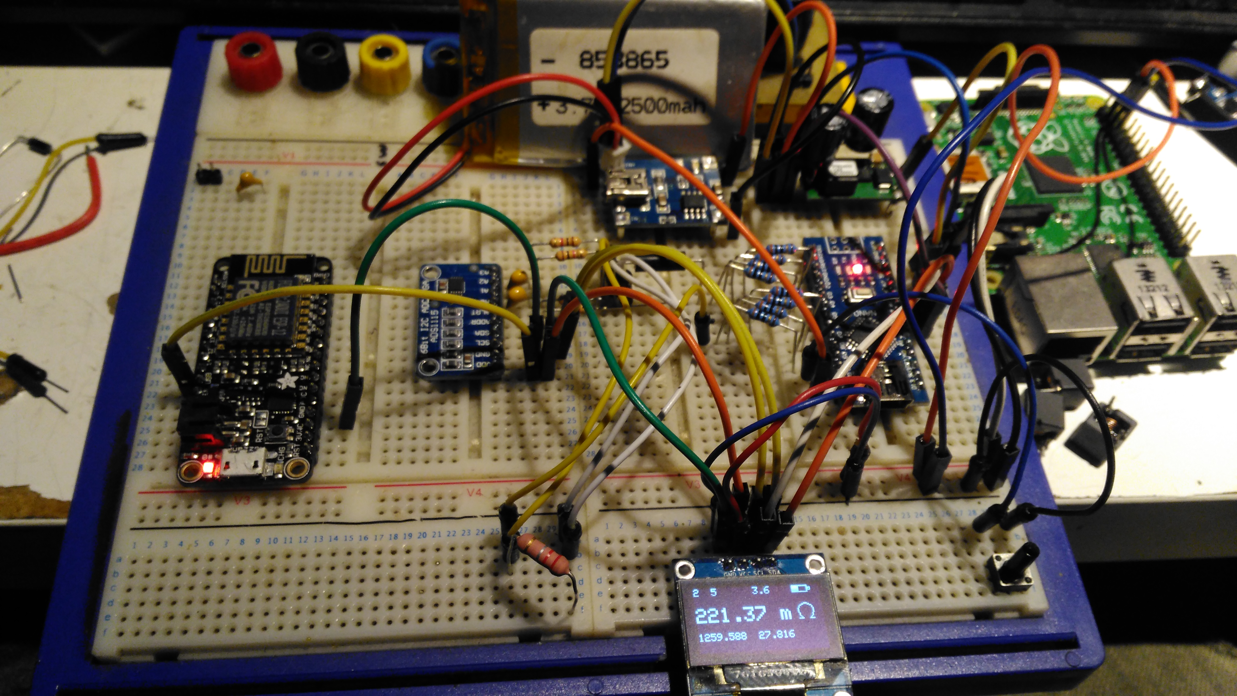
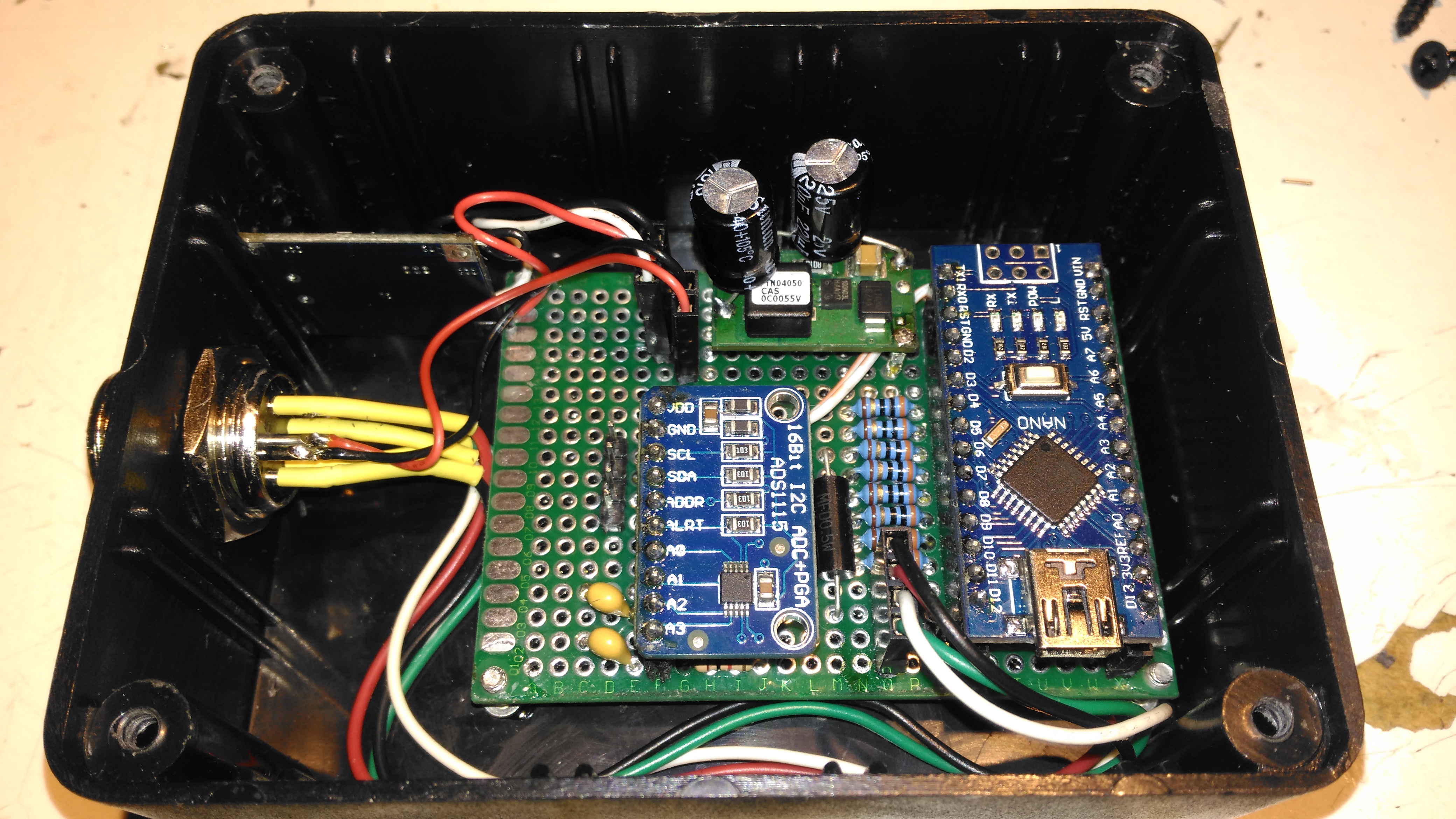
Final Prototype
Since I made some changes to both the software and the hardware components, I decided to prototype the changes on breadboard. The lithium cell is at the top of the image. with the charger module & DC-DC converter. The Arduino Nano is on the right, the ADC & reference resistor on the left, and the display at the bottom.
The Raspberry Pi & ESP8266 module are being used in this case to discharge the battery quicker to make sure the battery level calibration was correct, and to make sure the DC-DC converter would continue to function throughout the battery voltage range.
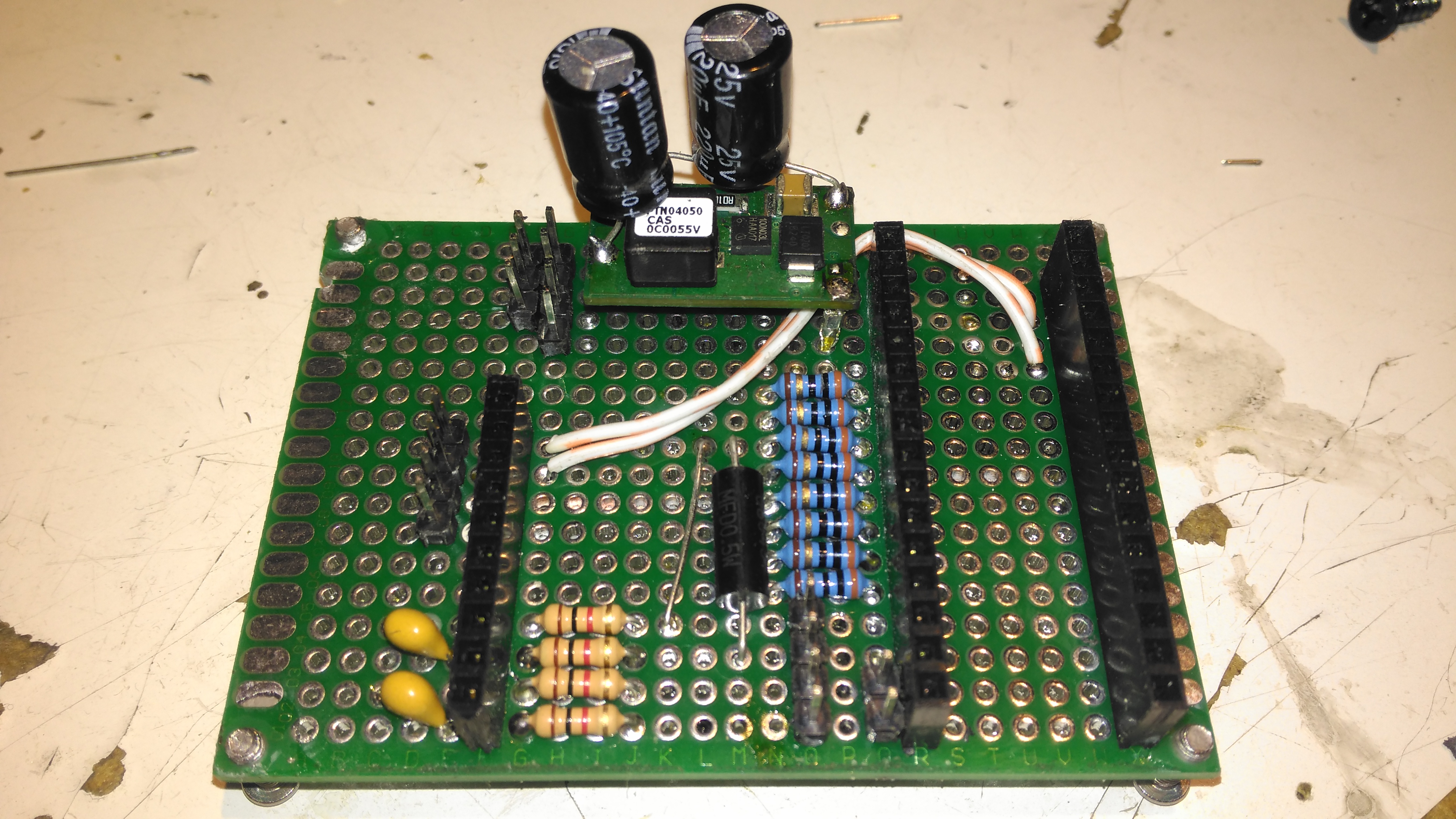
Matrix Board Passives
Here’s the final board with the passive components installed, along with the DC-DC converter. I used a Texas Instruments PTN04050 boost module for power as I had one spare.
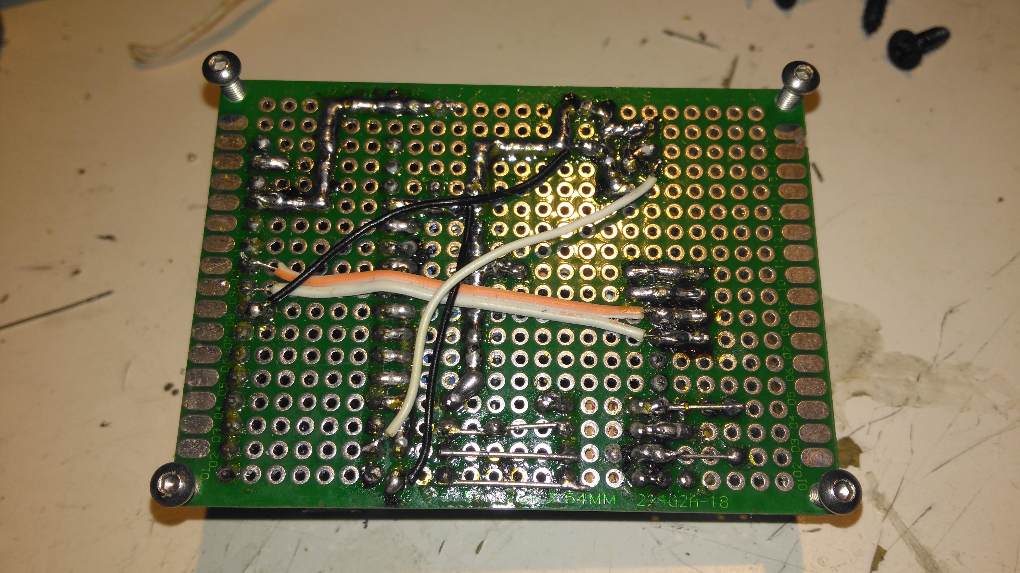
Matrix Board Rear
The bottom of the board has most of the wire jumpers for the I²C bus, and power sensing.
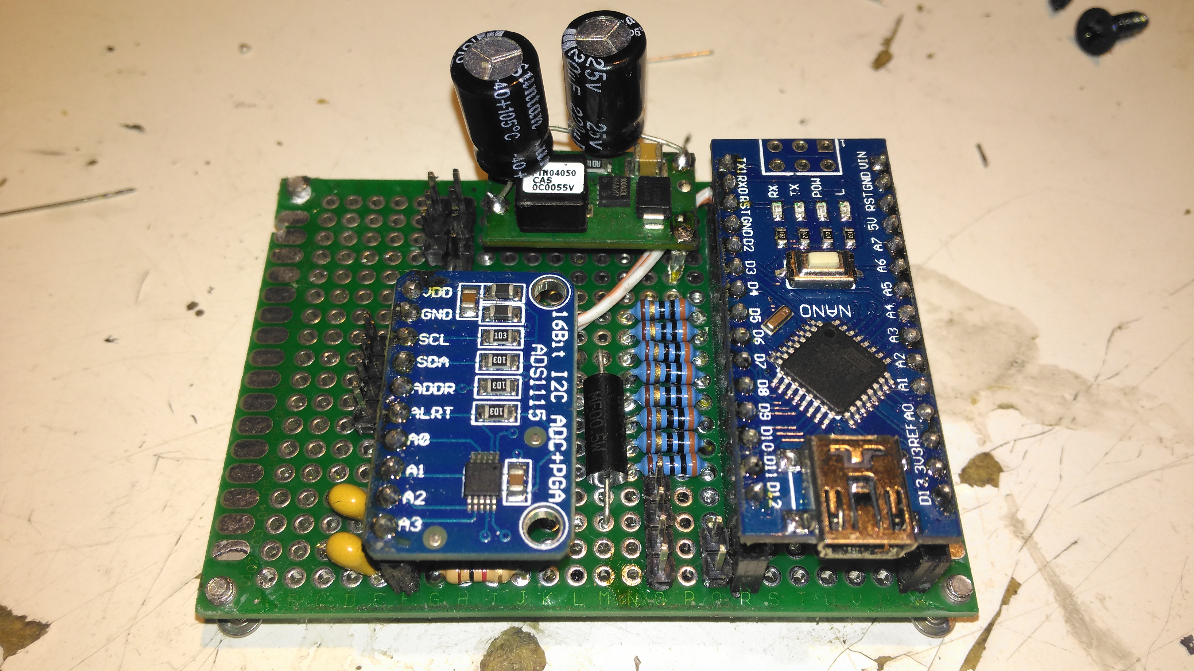
Matrix Board Modules
Here’s both modules installed on the board. I used an Arduino Nano instead of the Arduino Pro Mini that the original used as these were the parts I had in stock. Routing the analogue pins is also easier on the Mini, as they’re brought out to pins in the DIP footprint, instead of requiring wire links to odd spots on the module. To secure the PCB into the case without having to drill any holes, I tapped the corner holes of the matrix board M2.5 & threaded cap head screws in. These are then spot glued to the bottom of the case to secure the finished board.
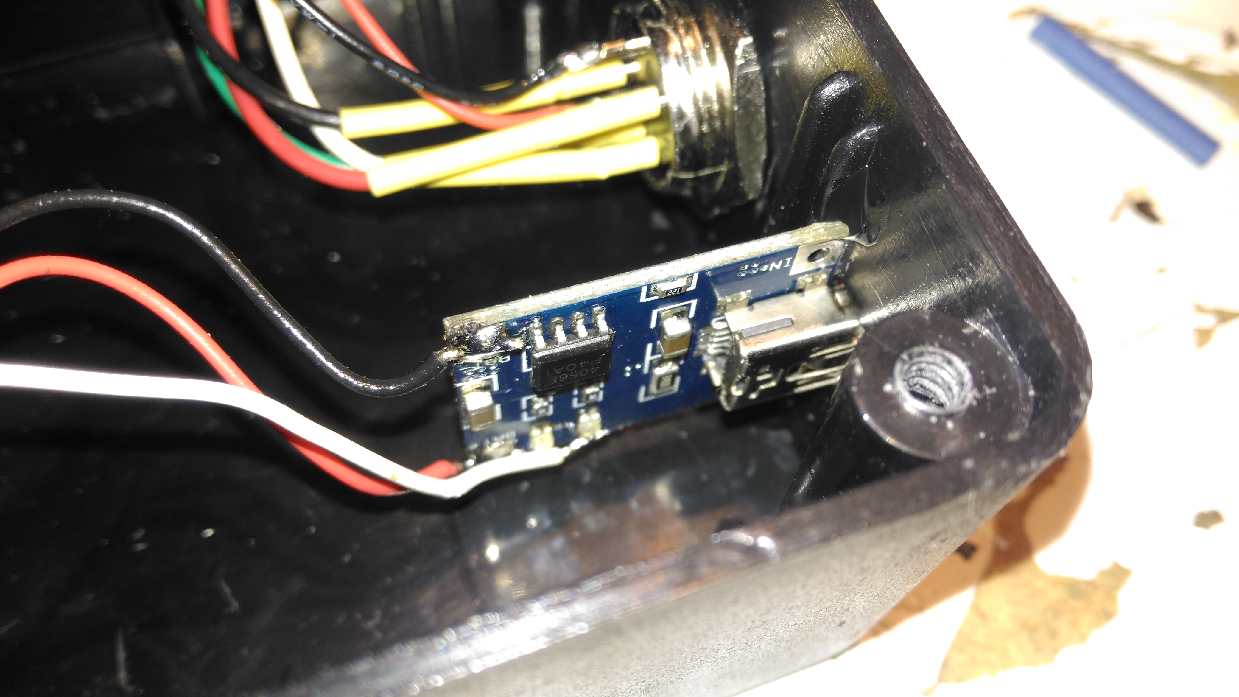
Lithium Charger
The lithium charger module is attached to the side of the enclosure, the third white wire is for input sensing – when the USB cable is plugged in a charge icon is shown on the OLED display.
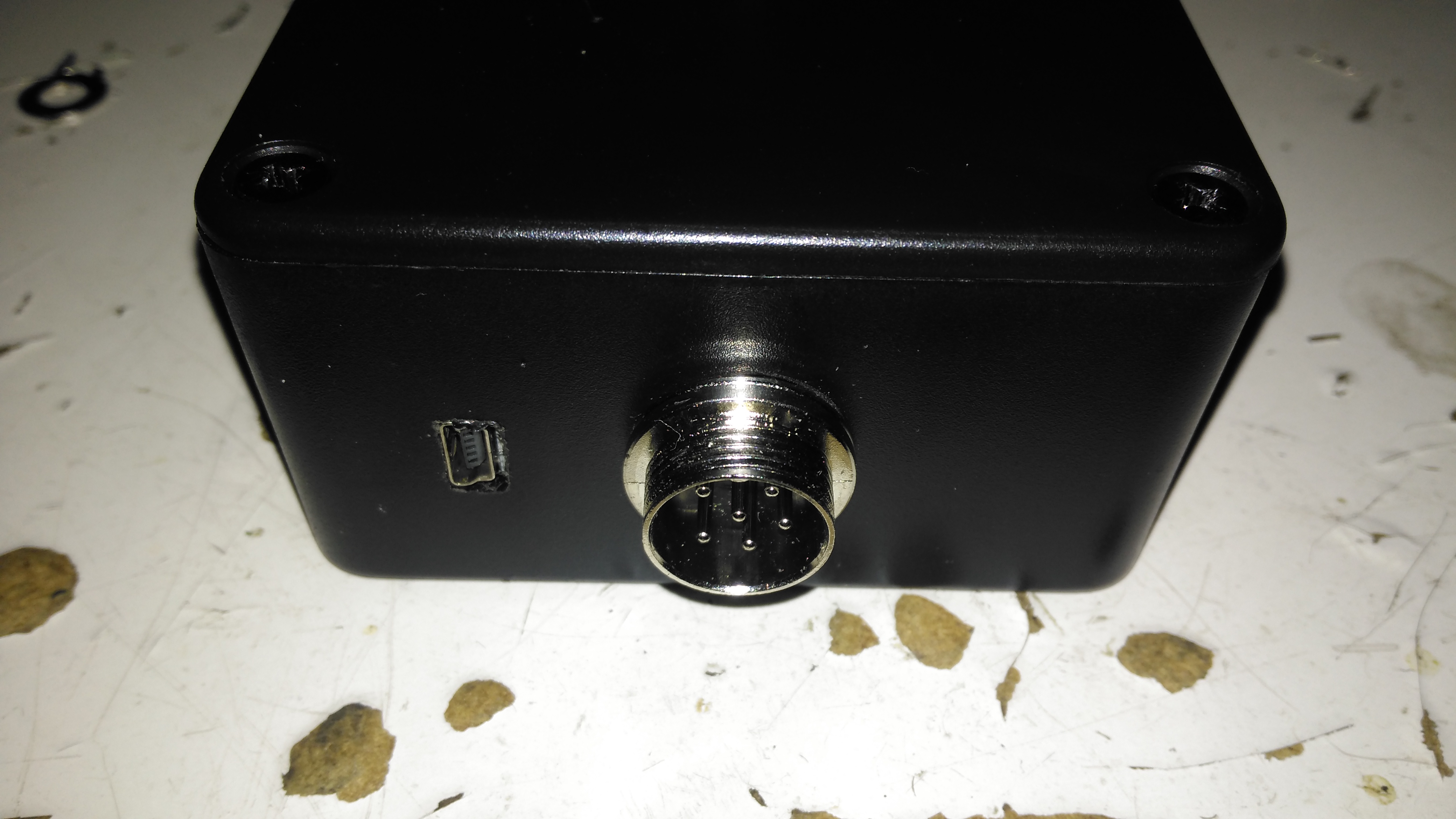
Input Connections
The inputs on the side of the enclosure. I’ve used the same 6-pin round connector for the probes, power is applied to the Arduino when the probes are plugged in.
Module Installed
Everything installed in the enclosure – it’s a pretty tight fit especially with the lithium cell in place.
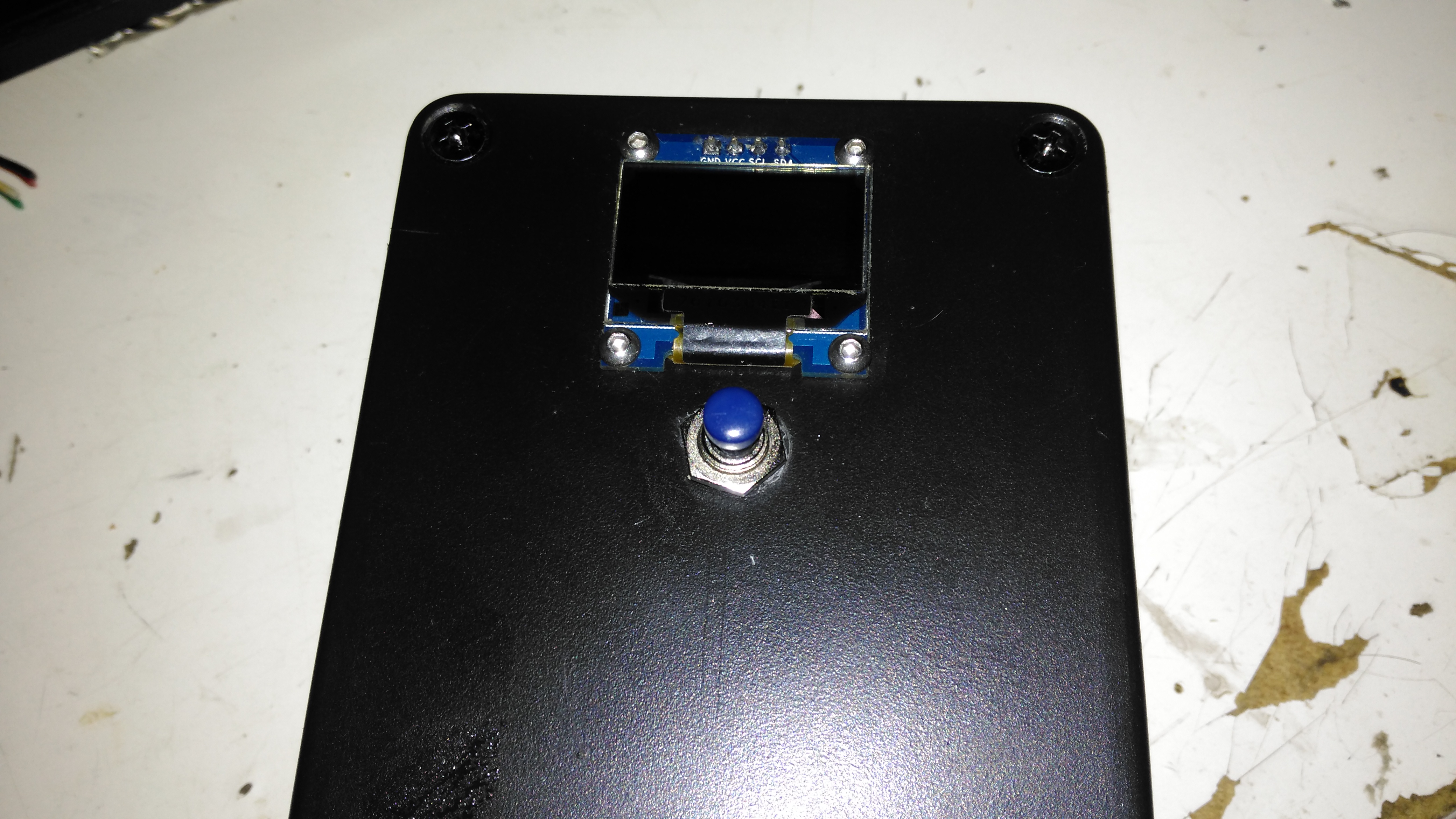
Meter Top Cover
The top cover has the Measure button, and the OLED display panel, the latter secured to the case with M2.5 cap head screws.
Kelvin Clips
Finally, the measurement loom, with Kelvin clips. These were an eBay buy, keeping things cheap. These clips seem to be fairly well built, even if the hinges are plastic. I doubt they’re actually gold-plated, more likely to be brass. I haven’t noticed any error introduced by these cheap clips so far.
The modified sketch is below:
// ---------------------------------------------------------------------------------------------
//  Simple, accurate milliohmeter
//
//  (c) Mark Driedger 2015
//
//  - Determines resistance using 4 wire measurement of voltage across a series connected
//  reference resistor (Rr, 10 ohm, 0.1%) and test resistor (Rx)
//  - range of accurate measurement is roughly 50 mohm to 10Kohm
//  - Uses Arduino digital I/O ports to deliver the test current, alternating polarity to cancel
//  offset errors (synchronous detector)
//  - 4 I/O pins are used for each leg of the test current to increase test current
//  - Averages 2 cycles and 100 samples/cycle
//  - Uses a 16 bit ADC ADS1115 with 16x PGA to improve accuracy
//
//  Version History
//    May 24/15    v1.0-v4.0
//      - initial development versions
//    May 27/15    v5.0
//      - changed display to I2C
//      - backed out low power module since it seemed to cause serial port upload problems
// ---------------------------------------------------------------------------------------------

#include <Wire.h>
#include <SPI.h>
#include <Adafruit_GFX.h>
#include <Adafruit_SSD1306.h>
//#include <LowPower.h>

#if (SSD1306_LCDHEIGHT != 64)
#error("Height incorrect, please fix Adafruit_SSD1306.h!");
#endif

// ---------------------------------------------------------------------------------------------
//  I/O port usage
// ---------------------------------------------------------------------------------------------
//    serial port (debug and s/w download)    0, 1
//    I²C interface to ADC & display          A4, A5
//    positive drive                          2, 3, 4, 5
//    push to test input                      8
//    unused                                  9, 10, 11, A0, A1, A2, A6, A7
//    negative drive                          6, 7, 8, 9
//    battery voltage monitor                 A3
//    debug output                            13

#define  P_PushToTest  10       // push button (measure), active low
#define  P_Debug       13
#define  CHG           12

//  ADS1115 mux and gain settings
#define  ADS1115_CH01  0x00    // p = AIN0, n = AIN1
#define  ADS1115_CH03  0x01    // ... etc
#define  ADS1115_CH13  0x02
#define  ADS1115_CH23  0x03
#define  ADS1115_CH0G  0x04    // p = AIN0, n = GND
#define  ADS1115_CH1G  0x05    // ... etc
#define  ADS1115_CH2G  0x06
#define  ADS1115_CH3G  0x07

#define  ADS1115_6p144  0x00   // +/- 6.144 V full scale
#define  ADS1115_4p096  0x01   // +/- 4.096 V full scale
#define  ADS1115_2p048  0x02   // +/- 2.048 V full scale
#define  ADS1115_1p024  0x03   // +/- 1.024 V full scale
#define  ADS1115_0p512  0x04   // +/- 0.512 V full scale
#define  ADS1115_0p256  0x05   // +/- 0.256 V full scale
#define  ADS1115_0p256B 0x06   // same as ADS1115_0p256
#define  ADS1115_0p256C 0x07   // same as ADS1115_0p256

Adafruit_SSD1306   display(0);               // using I2C interface, no reset pin
static int         debug_mode = 0;           // true in debug mode

float ADS1115read(byte channel, byte gain)
//--------------------------------------------------------------------------------------
//  reads a single sample from the ADS1115 ADC at a given mux (channel) and gain setting
//  - channel is 3 bit channel number/mux setting (one of ADS1115_CHxx)
//  - gain is 3 bit PGA gain setting (one of ADS1115_xpxxx)
//  - returns voltage in volts
//  - uses single shot mode, polling for conversion complete, default I2C address
//  - conversion takes approximatly 9.25 msec
//--------------------------------------------------------------------------------------
  {
  const int    address = 0x48;      // ADS1115 I2C address, A0=0, A1=0
  byte         hiByte, loByte;
  int          r;
  float        x;

  channel &= 0x07;                  // constrain to 3 bits
  gain    &= 0x07;

  hiByte = B10000001 | (channel<<4) | (gain<<1);    // conversion start command
  loByte = B10000011;

  Wire.beginTransmission(address);  // send conversion start command
  Wire.write(0x01);                 // address the config register
  Wire.write(hiByte);               // ...and send config register value
  Wire.write(loByte);
  Wire.endTransmission();

   do                               // loop until conversion complete
    {
    Wire.requestFrom(address, 2);   // config register is still addressed
    while(Wire.available())
      {
      hiByte = Wire.read();         // ... and read config register
      loByte = Wire.read();
      }
    }
  while ((hiByte & 0x80)==0);       // upper bit (OS) is conversion complete

  Wire.beginTransmission(address);
  Wire.write(0x00);                 // address the conversion register
  Wire.endTransmission();

  Wire.requestFrom(address, 2);     // ... and get 2 byte result
  while(Wire.available())
    {
    hiByte = Wire.read();
    loByte = Wire.read();
    }

  r = loByte | hiByte<<8;           // convert to 16 bit int
  switch(gain)                      // ... and now convert to volts
    {
      case ADS1115_6p144:  x = r * 6.144 / 32768.0; break;
      case ADS1115_4p096:  x = r * 4.096 / 32768.0; break;
      case ADS1115_2p048:  x = r * 2.048 / 32768.0; break;
      case ADS1115_1p024:  x = r * 1.024 / 32768.0; break;
      case ADS1115_0p512:  x = r * 0.512 / 32768.0; break;
      case ADS1115_0p256:
      case ADS1115_0p256B:
      case ADS1115_0p256C: x = r * 0.256 / 32768.0; break;
    }
  return x;
  }

// ---------------------------------------------------------------------------------------------
//  Drive functions
//   - ports 4-7 and A0-A3 are used to differentially drive resistor under test
//   - the ports are resistively summed to increase current capability
//   - DriveOff() disables the drive, setting the bits to input
//   - DriveOn()  enables the drive,  setting the bits to output
//   - DriveP()   enables drive with positive current flow (from ports 4-7 to ports A0-A3)
//   - DriveN()   enables drive with negative current flow
// ---------------------------------------------------------------------------------------------
void DriveP()
  {
    DriveOff();
    digitalWrite( 2, HIGH);
    digitalWrite( 3, HIGH);
    digitalWrite( 4, HIGH);
    digitalWrite( 5, HIGH);
    digitalWrite( 6, LOW);
    digitalWrite( 7, LOW);
    digitalWrite( 8, LOW);
    digitalWrite( 9, LOW);
    DriveOn();
  }

void DriveN()
  {
    DriveOff();
    digitalWrite( 2, LOW);
    digitalWrite( 3, LOW);
    digitalWrite( 4, LOW);
    digitalWrite( 5, LOW);
    digitalWrite( 6, HIGH);
    digitalWrite( 7, HIGH);
    digitalWrite( 8, HIGH);
    digitalWrite( 9, HIGH);
    DriveOn();
  }

void DriveOn()
  {
    pinMode( 2, OUTPUT);      // enable source/sink in pairs
    pinMode( 6, OUTPUT);
    pinMode( 3, OUTPUT);
    pinMode( 7, OUTPUT);
    pinMode( 4, OUTPUT);
    pinMode( 8, OUTPUT);
    pinMode( 5, OUTPUT);
    pinMode( 9, OUTPUT);
    delayMicroseconds(5000);  // 5ms delay
  }

void DriveOff()
  {
    pinMode( 2, INPUT);       // disable source/sink in pairs
    pinMode( 6, INPUT);
    pinMode( 3, INPUT);
    pinMode( 7, INPUT);
    pinMode( 4, INPUT);
    pinMode( 8, INPUT);
    pinMode( 5, INPUT);
    pinMode( 9, INPUT);
  }

int CalcPGA(float x)
// ---------------------------------------------------------------------------------------------
//   Calculate optimum PGA setting based on a sample voltage, x, read at lowest PGA gain
//     - returns the highest PGA gain that allows x to be read with 10% headroom
// ---------------------------------------------------------------------------------------------
  {
    x = abs(x);
    if (x>3.680) return ADS1115_6p144;
    if (x>1.840) return ADS1115_4p096;
    if (x>0.920) return ADS1115_2p048;
    if (x>0.460) return ADS1115_1p024;
    if (x>0.230) return ADS1115_0p512;
    else         return ADS1115_0p256;
  }

void BatteryIcon(float charge)
// ---------------------------------------------------------------------------------------------
//   Draw a battery charge icon into the display buffer without refreshing the display
//     - charge ranges from 0.0 (empty) to 1.0 (full)
// ---------------------------------------------------------------------------------------------
  {
    static const unsigned char PROGMEM chg[] =     // Battery Charge Icon
    { 0x1c, 0x18, 0x38, 0x3c, 0x18, 0x10, 0x20, 0x00 };

    int w = constrain(charge, 0.0, 1.0)*16;  // 0 to 16 pixels wide depending on charge
    display.drawRect(100, 0, 16, 7, WHITE);  // outline
    display.drawRect(116, 2,  3, 3, WHITE);  // nib
    display.fillRect(100, 0,  w, 7, WHITE);  // charge indication

    //battery charging indication
    pinMode(CHG, INPUT);
    if (digitalRead(CHG) == HIGH)
      display.drawBitmap(91, 0, chg, 8, 8, WHITE);
  }

void f2str(float x, int N, char *c)
// ---------------------------------------------------------------------------------------------
//    Converts a floating point number x to a string c with N digits of precision
//     - *c must be a string array of length at least N+3 (N + '-', '.', '\0')
//     - x must be have than N leading digits (before decimal) or "#\0" is returned
// ---------------------------------------------------------------------------------------------
  {
  int     j, k, r;
  float   y;

  if (x<0.0)                    // handle negative numbers
    {
      *c++ = '-';
      x = -x;
    }
  for (j=0; x>=1.0; j++)        // j digits before decimal point
    x /= 10.0;                  // .. and scale x to be < 1.0

  if (j>N)                      // return error string if too many digits
    {
      *c++ = '#';
      *c++ = '\0';
      return;
    }

  y = pow(10, (float) N);       // round to N digits
  x = round(x * y) / y;
  if (x>1.0)                    // if 1st digit rounded up ...
    {
      x /= 10.0;                // then normalize back down 1 digit
      j++;
    }

  for (k=0; k<N; k++)
    {
      r = (int) (x*10.0);        // leading digit as int
      x = x*10-r;                // remove leading digit and shift 1 digit

      *c++ = r + '0';            // add leading digit to string
      if (k==j-1 && k!=N-1)      // add decimal point after j digits
        *c++ = '.';              // ... unless there are N digits before decimal
    }
  *c++ = '\0';
  }

void DisplayResistance(float x)
// ---------------------------------------------------------------------------------------------
//    Adds the resistance value, x, to the display buffer without refreshing the display
//      - converts to kohm, milliohm or microohm if necessary
// ---------------------------------------------------------------------------------------------
  {
    static const unsigned char PROGMEM omega_bmp[] =     // omega (ohm) symbol
    { B00000011, B11000000,
      B00001100, B00110000,
      B00110000, B00001100,
      B01000000, B00000010,
      B01000000, B00000010,
      B10000000, B00000001,
      B10000000, B00000001,
      B10000000, B00000001,
      B10000000, B00000001,
      B10000000, B00000001,
      B01000000, B00000010,
      B01000000, B00000010,
      B01000000, B00000010,
      B00100000, B00000100,
      B00010000, B00001000,
      B11111000, B00011111 };

    char  s[8];
    char  prefix;

    if (x>=1000.0)          // display in killo ohms
      {
        x /= 1000.0;
        prefix = 'k';
      }
    else if (x<0.001)       // display in micro ohms
      {
        x *= 1000000.0;
        prefix = 0xe5;    // mu
      }
    else if (x<1.0)         // display in milli ohms
      {
        x *= 1000.0;
        prefix = 'm';
      }
    else
      prefix = ' ';         // display in ohms

    f2str(x, 5, s);

    // display computed resistance
    display.setTextSize(2);
    display.setTextColor(WHITE);
    display.setCursor(0,20);
    display.print(s);

    // display prefix
    display.setCursor(85,20);
    display.print(prefix);

    // display omega (ohms) symbol
    display.drawBitmap(103, 18, omega_bmp, 16, 16, WHITE);
  }

void DisplayDebug(int a, int b, float x, float y, float Vbat)
// ---------------------------------------------------------------------------------------------
//    Adds debug info to the display buffer without showing the updated display
//      - Adds 2 ints (a, b) and a float(Vbat) to the top line and 2 floats (x, y)
//      to the bottom line+, all in small (size 1) text
// ---------------------------------------------------------------------------------------------
  {
    // display x, y in lower left, small font
    display.setTextSize(1);
    display.setCursor(0,45);
    display.print(x,3);
    display.print("  ");
    display.print(y,3);

    // display a, b in upper left, small font
    display.setTextSize(1);
    display.setCursor(0,0);
    display.print(a);
    display.print("  ");
    display.print(b);

    // display Vbat in upper middle, small font
    display.setTextSize(1);
    display.setCursor(60,0);
    display.print(Vbat,1);
  }

void DisplayStr(char *s)
// ---------------------------------------------------------------------------------------------
//    Adds a string, s, to the display buffer without refreshing the display @ (0,20)
// ---------------------------------------------------------------------------------------------
  {
    display.setTextSize(2);
    display.setTextColor(WHITE);
    display.setCursor(8,20);
    display.print(s);
  }

#ifdef TESTMODE
void loop()
  {
    while (digitalRead(P_PushToTest))
      ;
    DriveP();
    display.clearDisplay();
    DisplayStr("Drive: +");
    display.display();
    delay(250);

    while (digitalRead(P_PushToTest))
      ;
    DriveN();
    display.clearDisplay();
    DisplayStr("Drive: -");
    display.display();
    delay(250);

    while (digitalRead(P_PushToTest))
      ;
    DriveOff();
    display.clearDisplay();
    DisplayStr("Drive: Off");
    display.display();
    delay(250);
  }
#endif

void setup()
// ---------------------------------------------------------------------------------------------
//    - initializae display and I/O ports
// ---------------------------------------------------------------------------------------------
  {
    DriveOff();                                    // disable current drive
    Wire.begin();                                  // join I2C bus
    display.begin(SSD1306_SWITCHCAPVCC, 0x3c, 0);  // initialize display @ address 0x3c, no reset
    pinMode(P_PushToTest, INPUT_PULLUP);           // measure push button switch, active low
    debug_mode = !digitalRead(P_PushToTest);       // if pushed during power on, then debug mode
    pinMode(P_Debug, OUTPUT);                      // debug port
  }

void loop()
// ---------------------------------------------------------------------------------------------
//    main measurement loop
// ---------------------------------------------------------------------------------------------
  {
    const float      Rr = 10.0;             // reference resistor value, ohms
    const float      Rcal = 1.002419;       // calibration factor
    const int        N = 2;                 // number of cycles to average
    const int        M = 50;                // samples per half cycle
    static long      Toff;
    double           Rx;                    // calculated resistor under test, ohms
    byte             PGAr, PGAx;            // PGA gains (r = reference, x = test resistors)
    float            Vr, Vx, Wx, Wr;        // voltages in V
    float            Rn;                    // calculated resistor under test, ohms, single sample
    double           Avgr, Avgx;            // average ADC readings in mV
    int              j, k, n;
    float            Vbat;                  // battery voltage in V (from 2:1 divider)
    char             serialbuff[10];        // Buffer for sending the reading over I²C

    display.clearDisplay();
    DisplayStr("measuring");
    display.display();

    // determine PGA gains
    DriveP();
    Wr =  ADS1115read(ADS1115_CH01, ADS1115_6p144);
    Wx =  ADS1115read(ADS1115_CH23, ADS1115_6p144);
    DriveN();
    Vr = -ADS1115read(ADS1115_CH01, ADS1115_6p144);
    Vx = -ADS1115read(ADS1115_CH23, ADS1115_6p144);

    //  measure battery voltage ... while drive is on so there is a load
    Vbat = analogRead(A3)*5.0/1024.0;    // 2:1 divider (5V FS) on 4.2v lithium battery

    DriveOff();

    PGAr = CalcPGA(max(Vr, Wr));           // determine optimum PGA gains
    PGAx = CalcPGA(max(Vx, Wx));

    // measure resistance using synchronous detection
    Avgr = Avgx = 0.0;                     // clear averages
    Rx = 0.0;
    n = 0;
    for (j=0; j<N; j++)                    // for each cycle
      {
        DriveP();                          // turn on drive, positive
        for (k=0; k<M; k++)
          {
            digitalWrite(P_Debug, 1);
            Vx = ADS1115read(ADS1115_CH23, PGAx);
            digitalWrite(P_Debug, 0);
            Vr = ADS1115read(ADS1115_CH01, PGAr);
            Avgx += Vx;
            Avgr += Vr;
            Rn = Vx/Vr;
            if (Rn>0.0 && Rn<10000.0)
              {
              Rx += Rn;
              n++;
              }
          }

        DriveN();                          // turn on drive, negative
        for (k=0; k<M; k++)
          {
            digitalWrite(P_Debug, 1);
            Vx = ADS1115read(ADS1115_CH23, PGAx);
            digitalWrite(P_Debug, 0);
            Vr = ADS1115read(ADS1115_CH01, PGAr);
            Avgx -= Vx;
            Avgr -= Vr;
            Rn = Vx/Vr;
            if (Rn>0.0 && Rn<10000.0)
              {
              Rx += Rn;
              n++;
              }
          }
      }

    DriveOff();
    Rx   *= Rr * Rcal / n;                 // apply calibration factor and compute average
    Avgr *= 1000.0 / (2.0*N*M);            // average in mV
    Avgx *= 1000.0 / (2.0*N*M);

    // display the results ... battery icon, Rx measurement, debug info if requested
    display.clearDisplay();                // ... and display result
    BatteryIcon((Vbat-3.0)/(4.2-3.0));     // 7.5V = 0%, 9V = 100%
    //display.drawLine(0, 8, 127, 8, WHITE); //Draw separator line under icons
    if (n==0){                              // no measurement taken ...
      display.setTextSize(2);
      display.setCursor(51,20);
      display.print(F("OL"));
    }
      //DisplayStr("-----");
    else
      DisplayResistance(Rx);
    //Send Reading via I²C
      Wire.beginTransmission(0x50);
      Wire.write(dtostrf(Rx, 5, 5, serialbuff));
      Wire.endTransmission();
    if (debug_mode)
      DisplayDebug(PGAr, PGAx, Avgr, Avgx, Vbat);
    display.display();                     // show the display

    // and then wait for next measurement request
    Toff = millis()+60000L;
    while(digitalRead(P_PushToTest))       // loop until measure button pressed
      {
        // Enter power down state for 120ms with ADC and BOD module disabled
        //LowPower.powerDown(SLEEP_120MS, ADC_OFF, BOD_OFF);
        if (millis()>Toff)                 // after 7 seconds ...
          {
            display.clearDisplay();        // clear display
            display.display();
          }
      }
  }
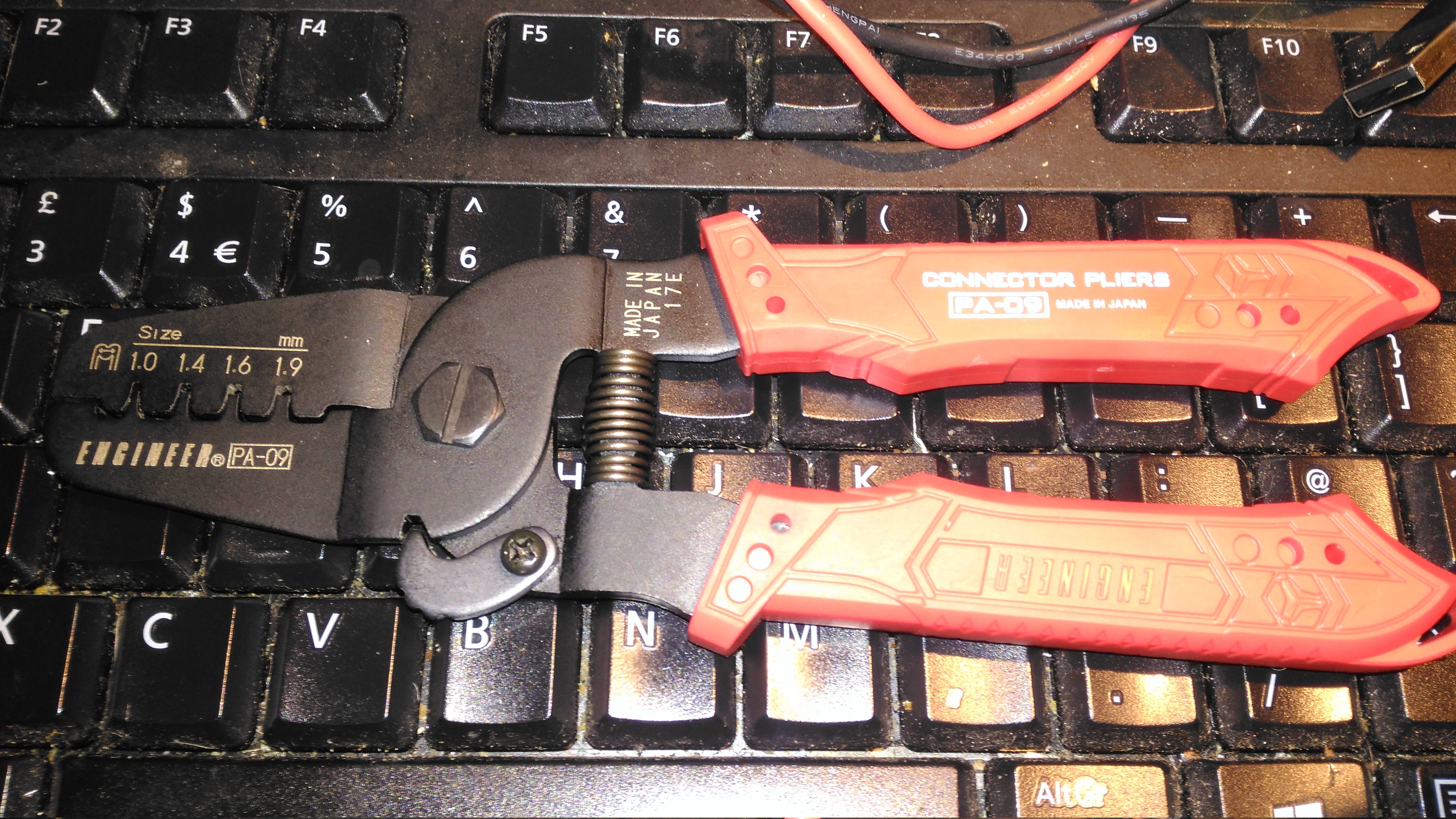
For a while now I’ve been attaching terminals such as Molex KK Dupont, & JST PH to wire ends with a lot of patience & a very fine soldering iron, however this method takes a lot of time, and with terminals like Dupont types, the terminal won’t fit into the connector body properly unless it’s crimped correctly. Official tools from the likes of JST or Molex are hilariously expensive, (~£250 for the Molex KK tool), and each tool only does a single connector series, so these are out of the picture. The cheapest available tool (~£40) for these types of terminals is the Engineer PA-09:
Engineer PA-09
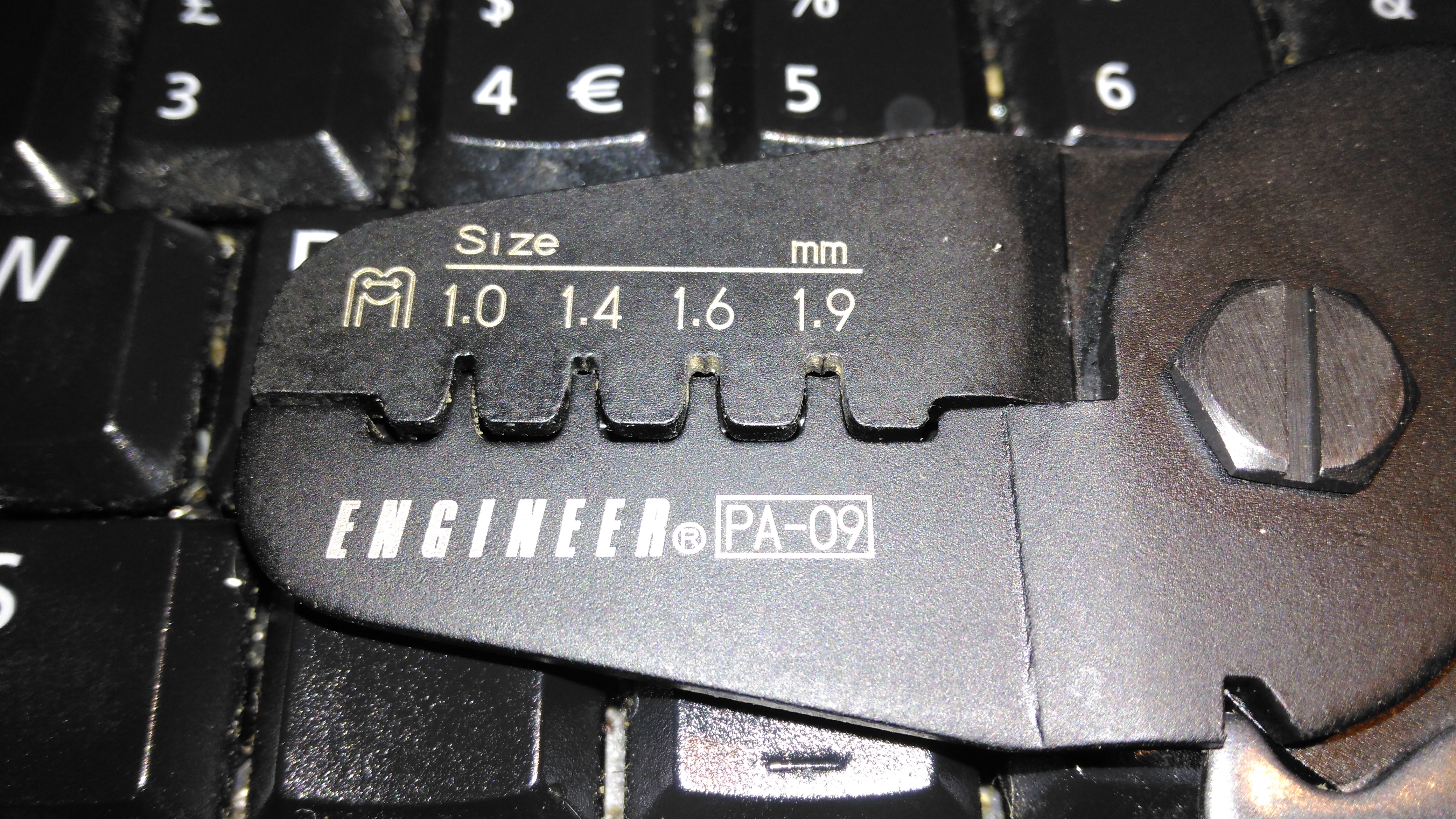
These are simple crimping pliers, with no niceties like a ratchet mechanism, but nonetheless they work very well for the cost. The PA-09 can handle terminals from 1mm-1.9mm, there is another tool, the PA-21, which crimps terminals from 1.6mm-2.5mm. The fit & finish is good – proper steel (S55C high carbon steel according to Engineer), not the steel-plated-cheese that most cheap Chinese tools are fabricated from, the handles are solid & comfortable.
Handles
The rubber handles are press-fit onto the steel frame arms of the pliers, and don’t slip off readily.
Die Head
The dies are well formed in the steel, and seem to be machined rather than stamped on a press, however the black oxide finish hides any machining marks. The smallest 1mm dies do seem to be a little fragile as they’re so small, so wouldn’t take much abuse without shearing off.
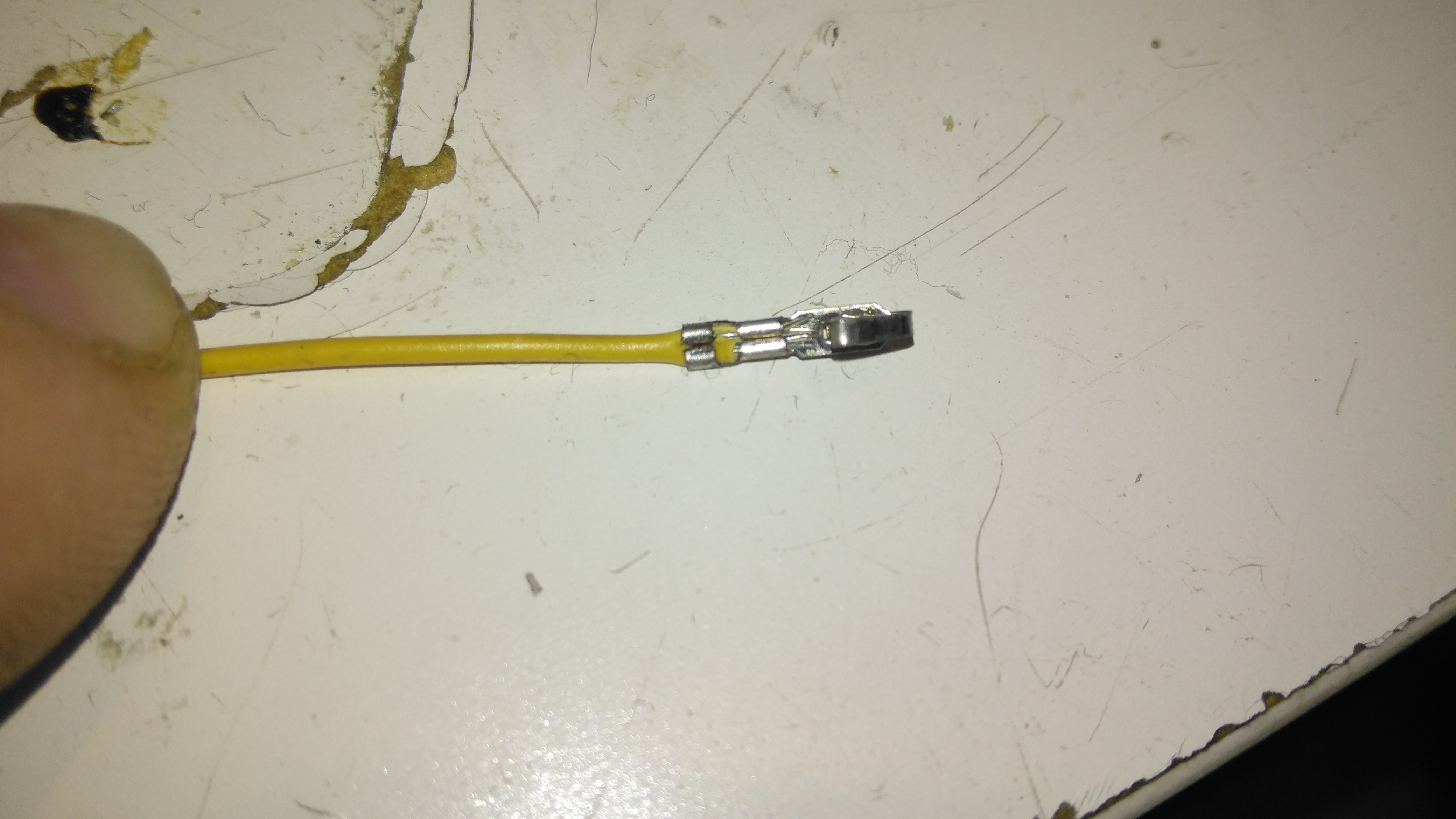
Crimped Molex KK Pin
Here’s a Molex KK pin that’s been crimped with the PA-09. The insulation crimp has pierced the insulation slightly, but this isn’t much of a problem. The conductor crimp is nice & tight, and everything is small enough to fit correctly into the plastic connector body. The trick with these tools is getting a feel for when the crimp is done – squeeze too tightly & the contact deforms, not tightly enough & the wire will just pull out of the terminal. The official tools also crimp both the conductor & insulation at the same time, and they also hold the terminal in place while the wire is inserted. In these cheaper tools, the crimps are done separately, but they do hold on to the contact securely enough for the wire to be inserted properly with your spare hand.
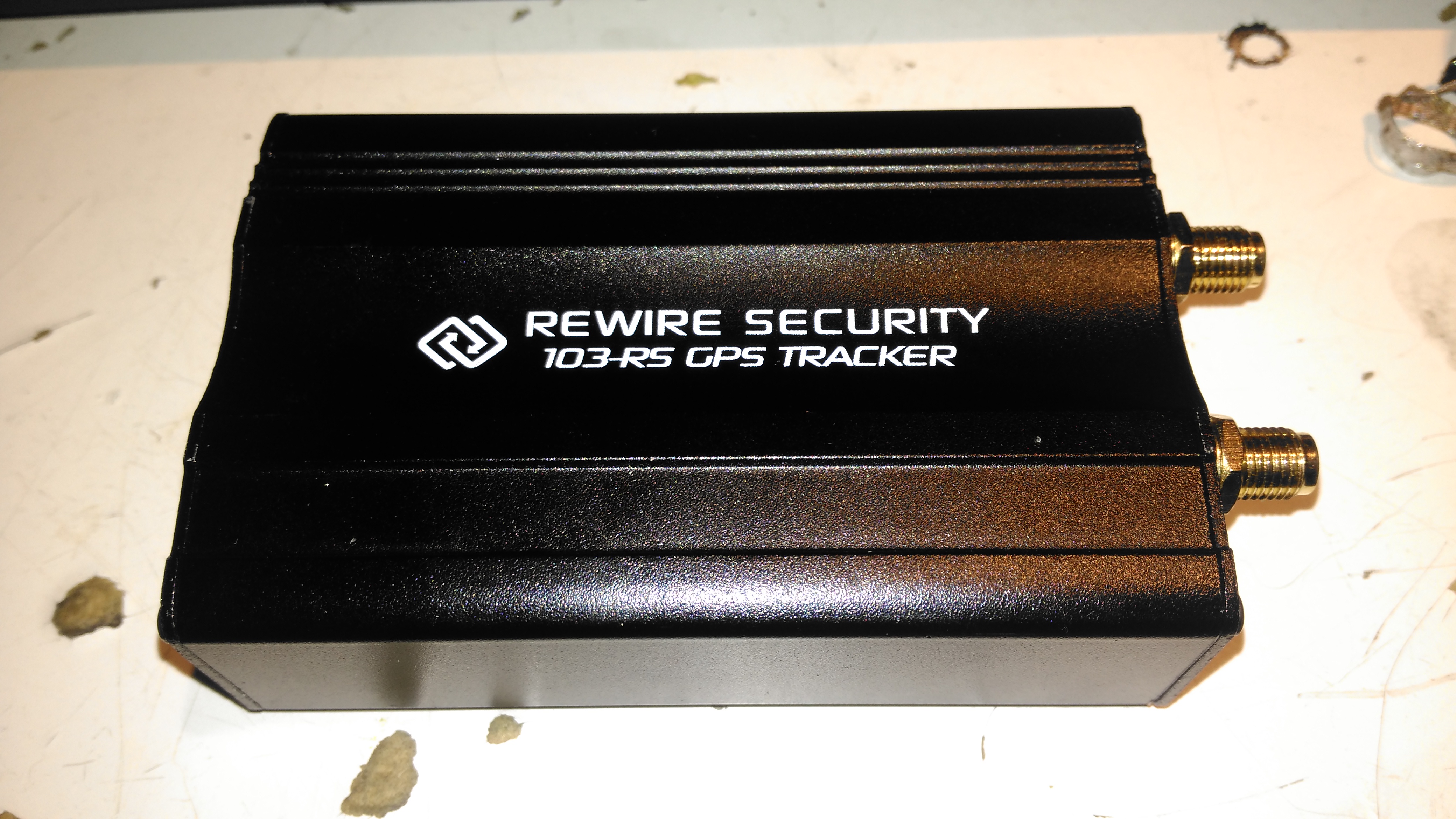
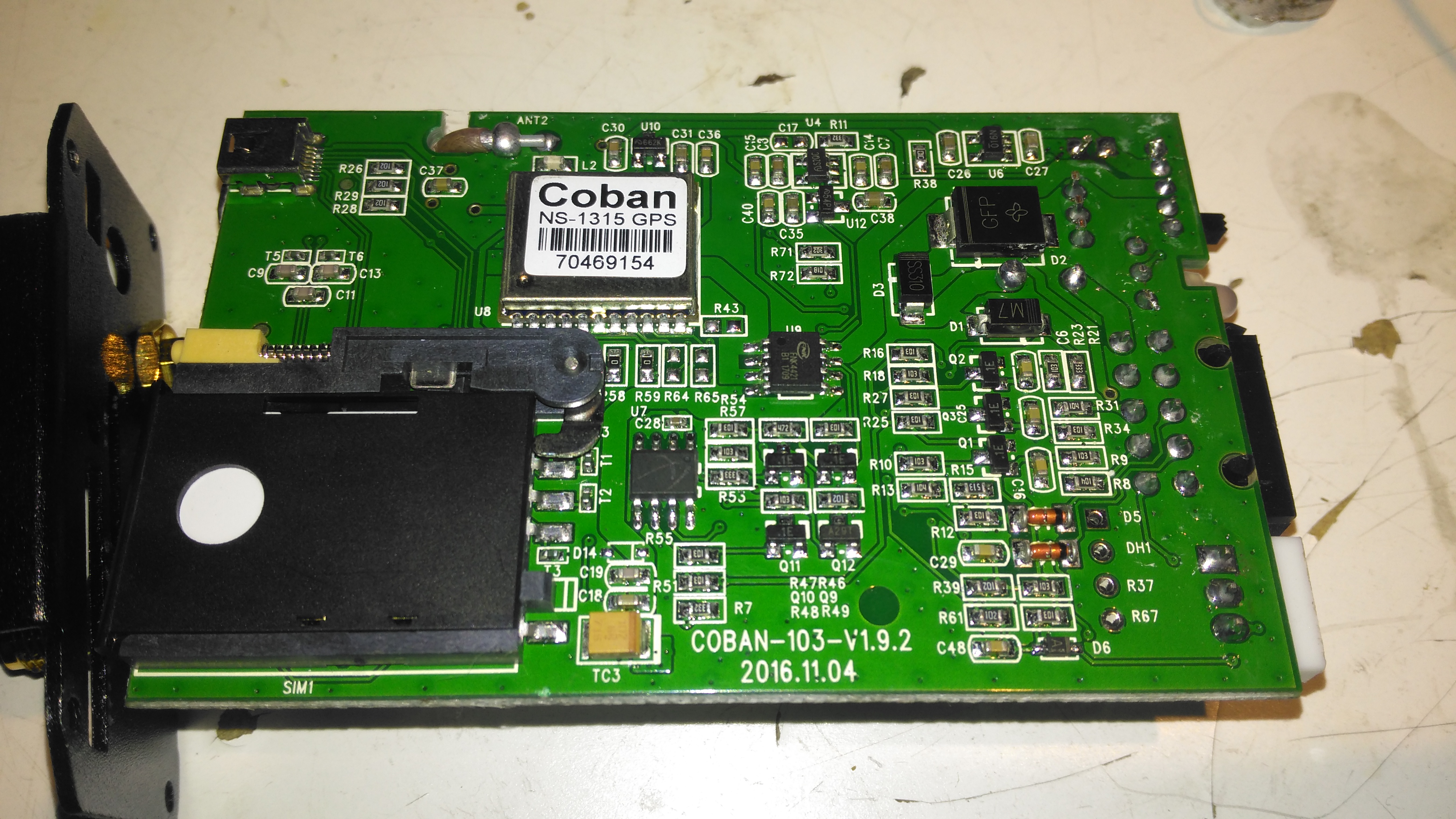
I thought it was time to add a bit of security to the gear I take camping, so this GPS tracker unit was sourced from eBay. This is a Rewire Security 103RS, a slightly customised version of the common Chinese TK103 GPS tracker.
Input Connections
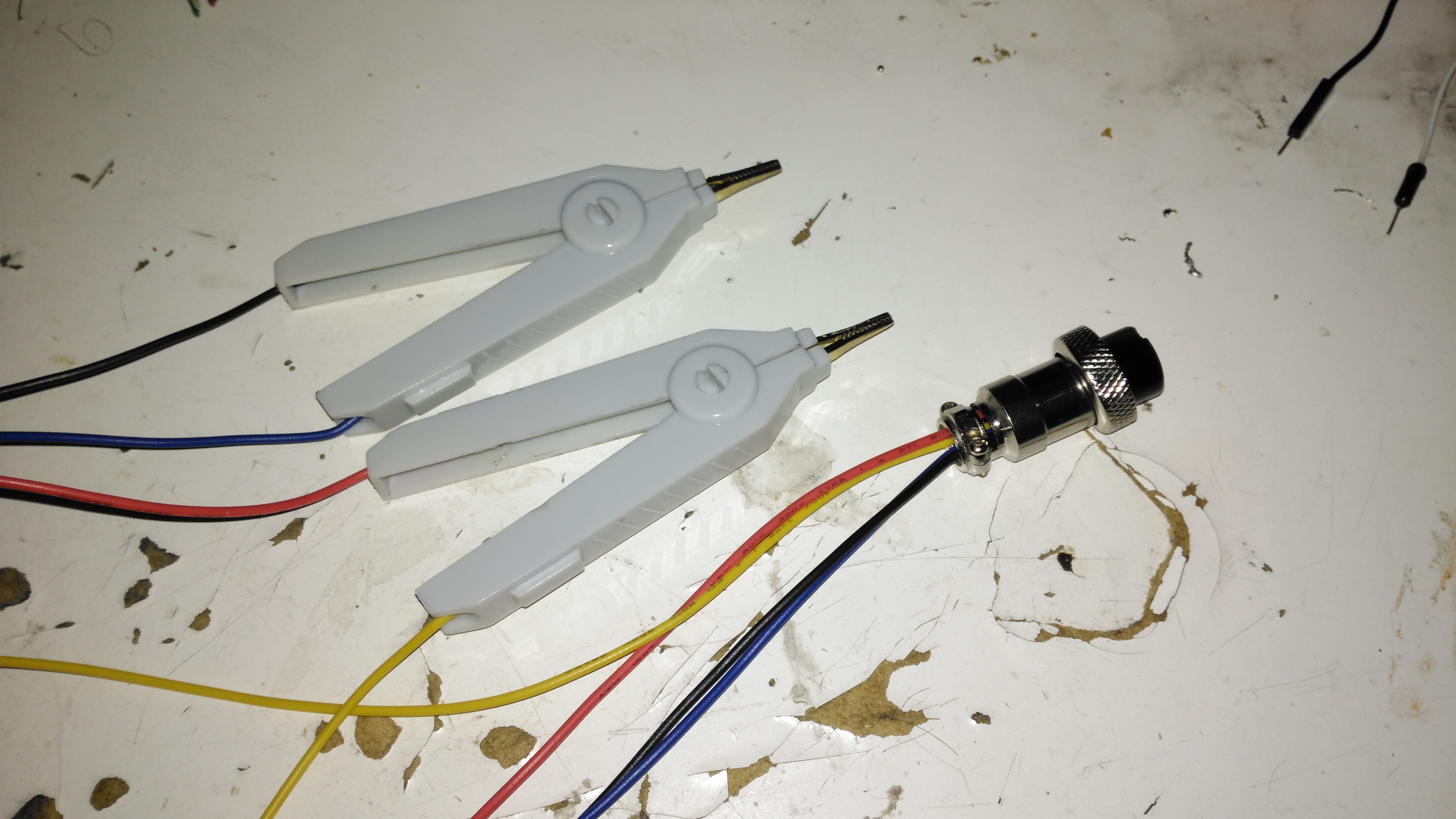
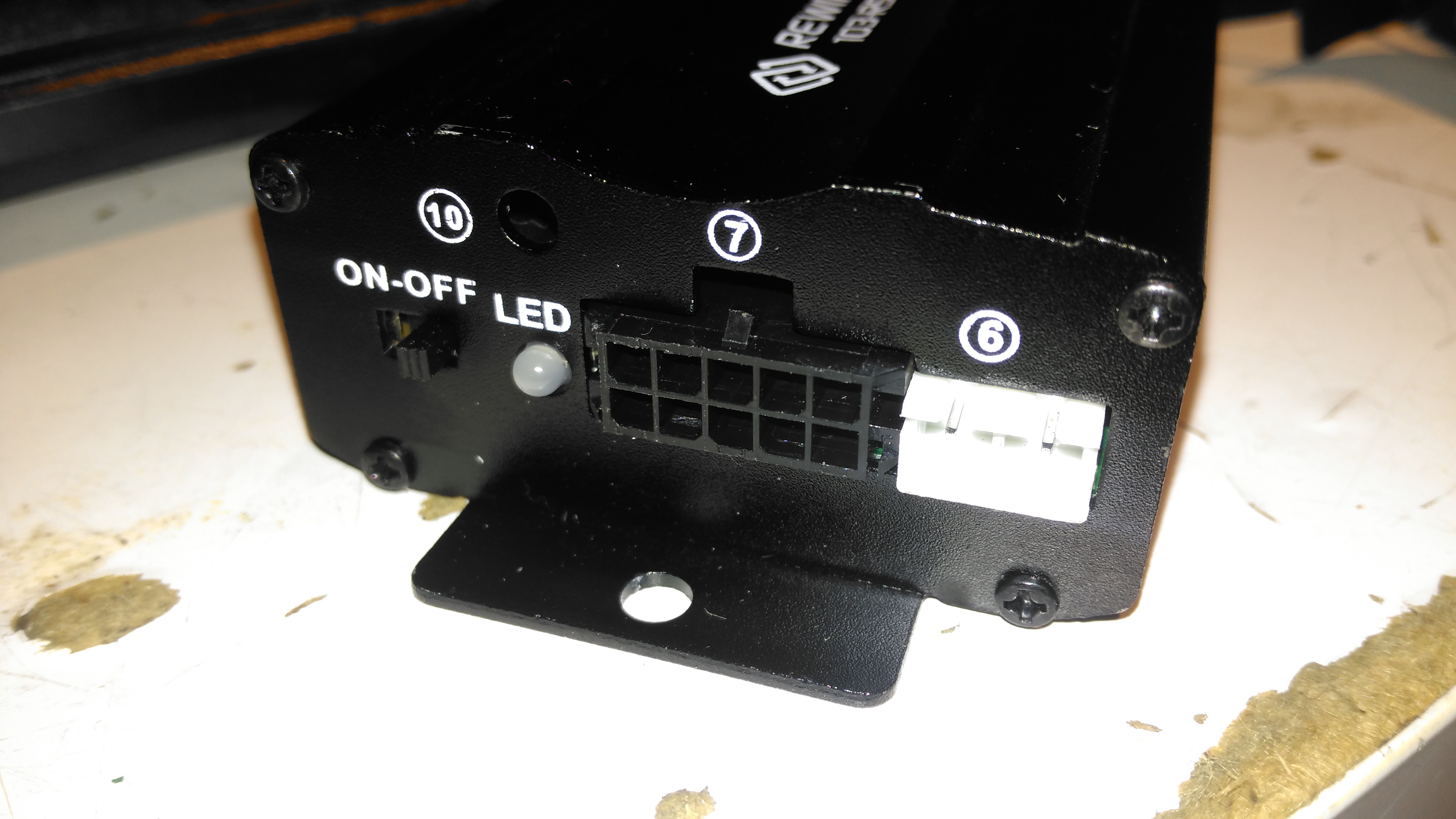
The small module has all it’s power connections on one end of the unit, on a Molex multi-way block. The white connector is for a piezo-shock sensor – this interfaces with the alarm functionality of the unit. There’s an indicator LED for both the GPS & GSM status, and a switch for the backup battery.
Antenna Connections
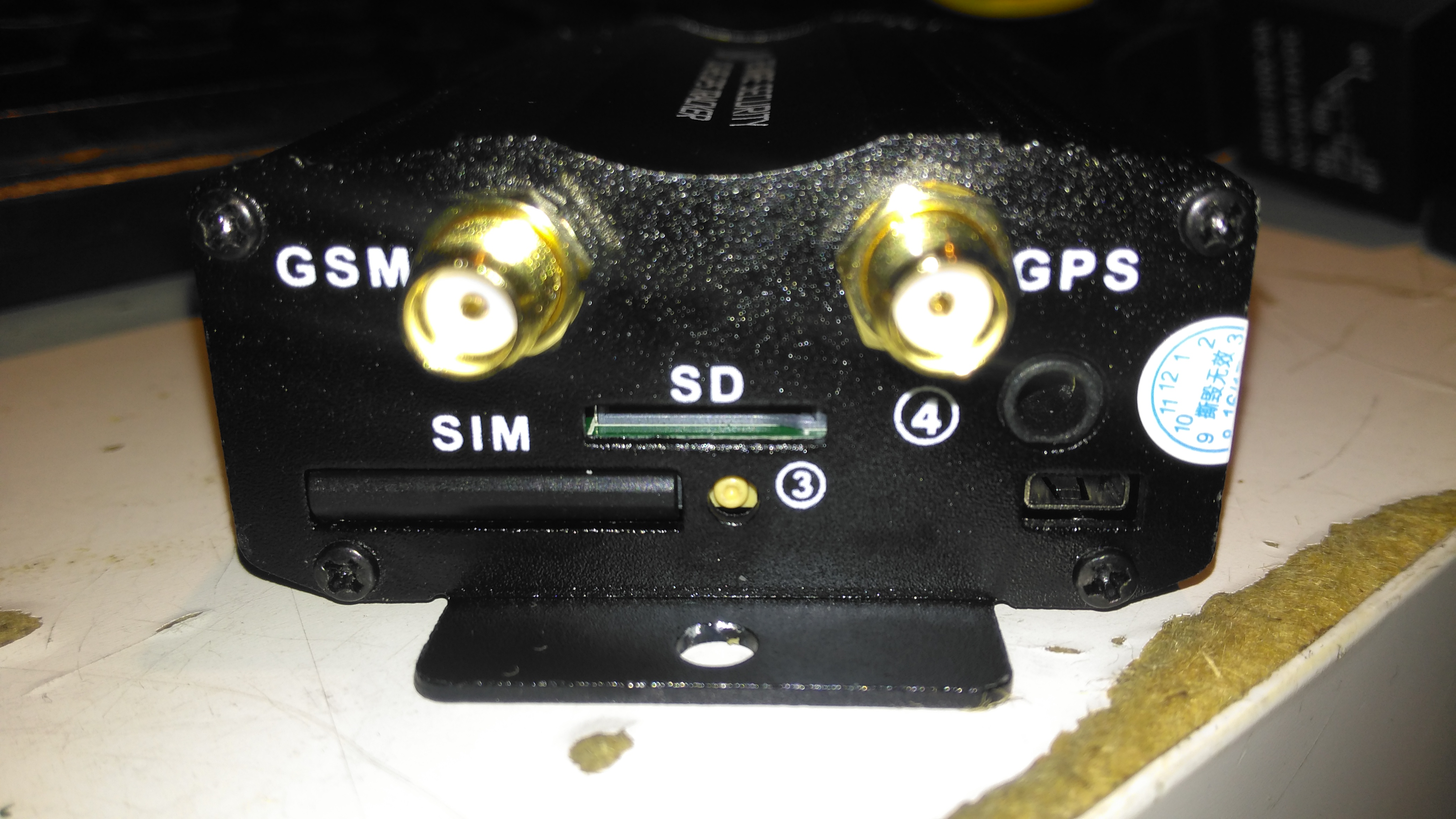
The other end has the antenna connections, microphone connection for the monitor function, along with the SIM & SD card slots.
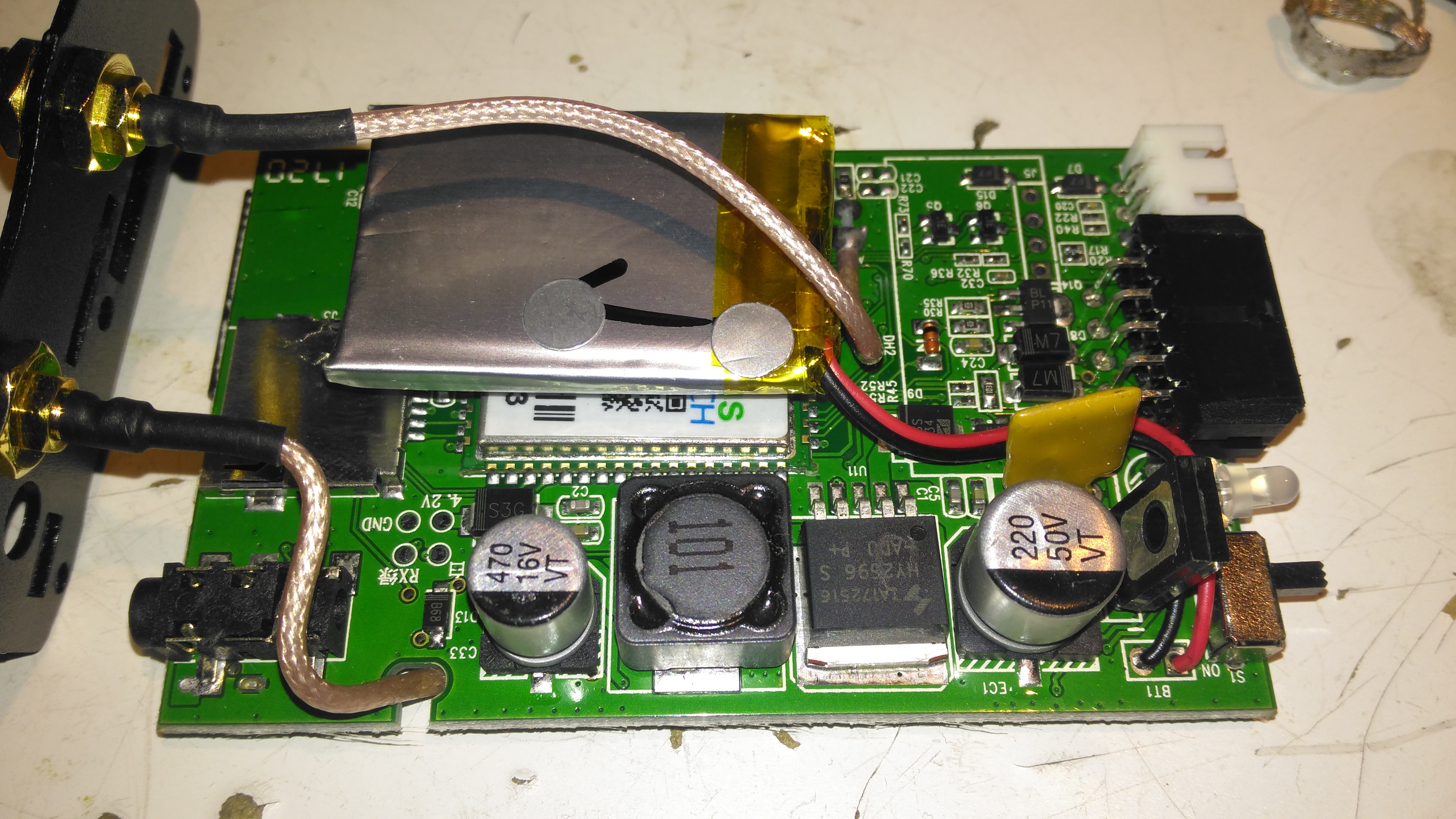
PCB Top
Once the end panel is removed, the PCB just slides out of the aluminium extruded casing. It’s pretty heavily packed with components in here. A switching regulator deals with the 12v input from the vehicle battery, and is protected by a polyfuse on the right. The GSM module is hiding under the Li-Po backup cell, unfortunately the sticky pad used to secure this wouldn’t come off without damaging something. The pigtails for both the GPS & GSM antennas are permanently soldered to the board here.
PCB Bottom
The bottom of the PCB has the GPS module, and mainly input protection & bypassing components. There is a FNK4421 Dual P-Channel MOSFET here as well, probably used for switching the external relay or alarm siren. The SIM socket for the GSM modem is located here in the corner.
In an effort to reduce the level of superflous stock I have in the workshop, I’ve set up a new store to sell off some of these parts & modules. It can be found over at store.experimental-engineering.co.uk. I’m still building the inventory, and new items are being added all the time. The money raised will go towards new posts & projects.
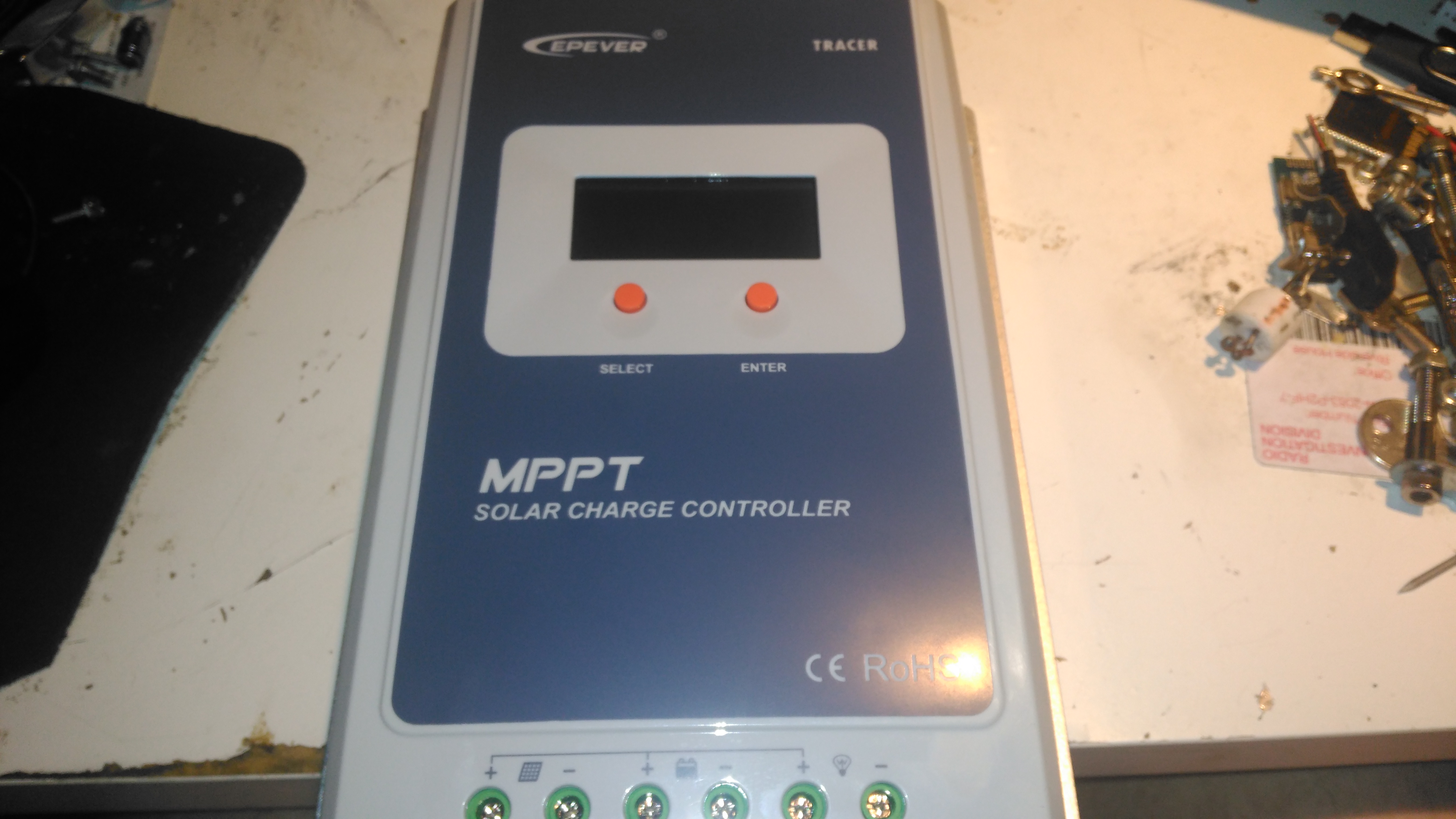
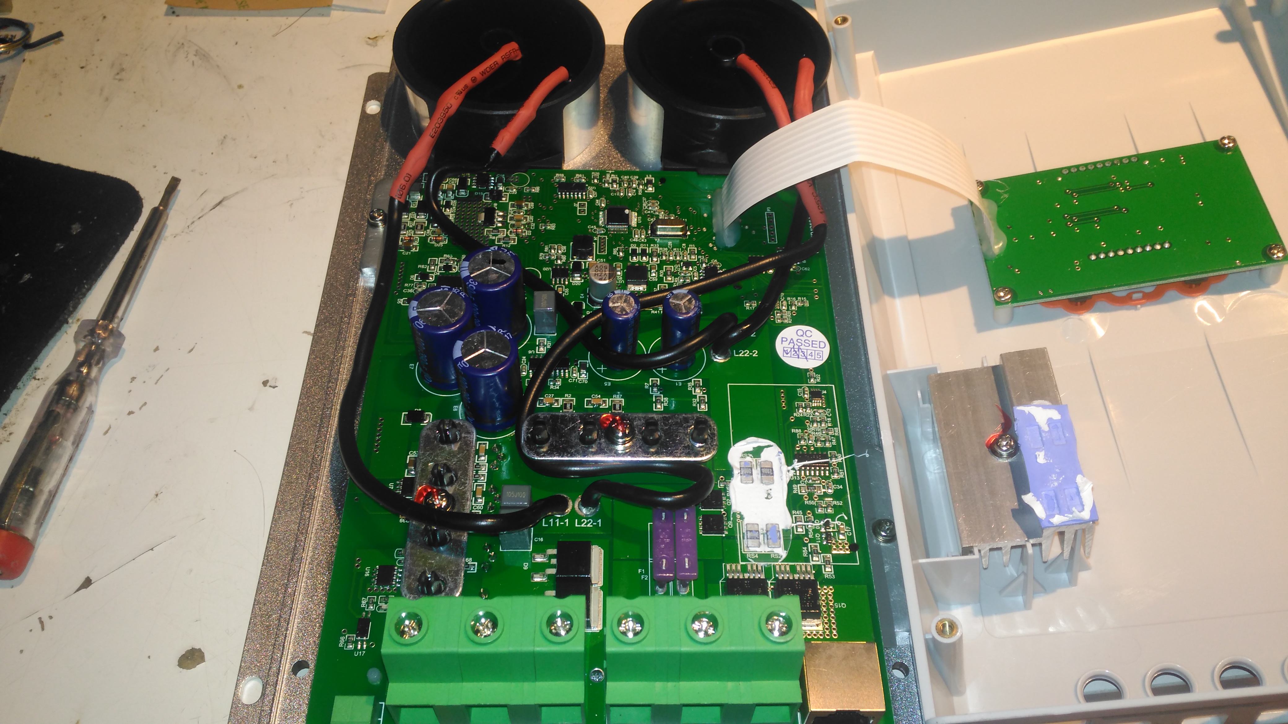
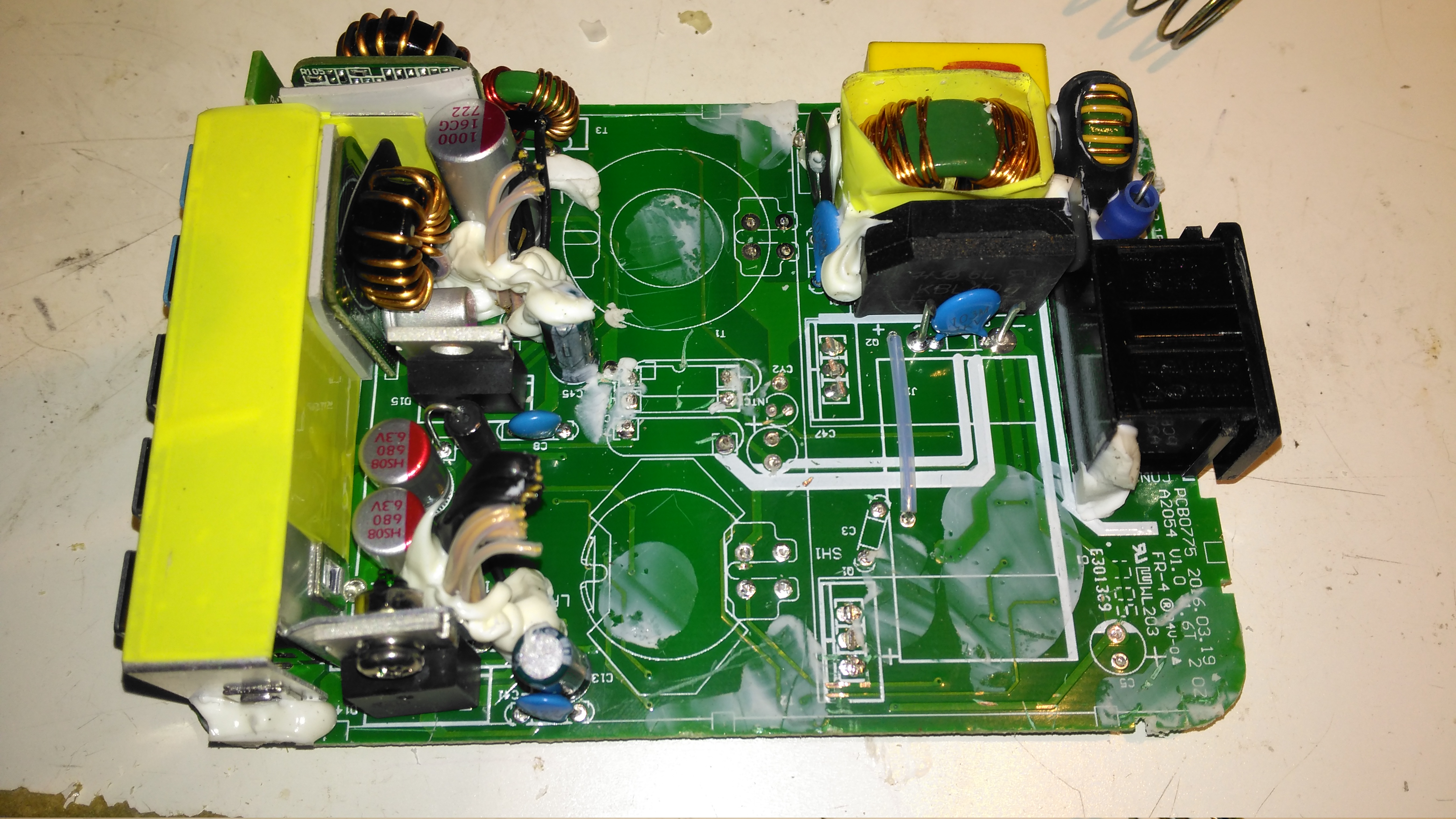
Here’s the solar charge controller to go with the MT50 from the last post. This is the 40A version of the EpEver Tracer A series, the 4210A. This unit is large, and very heavy. Most of this weight comes from the enormous heatsink which doubles as the mounting plate for all the other components, and the large inductors that are going to be required for the DC-DC conversion that MPPT requires.
Front Panel
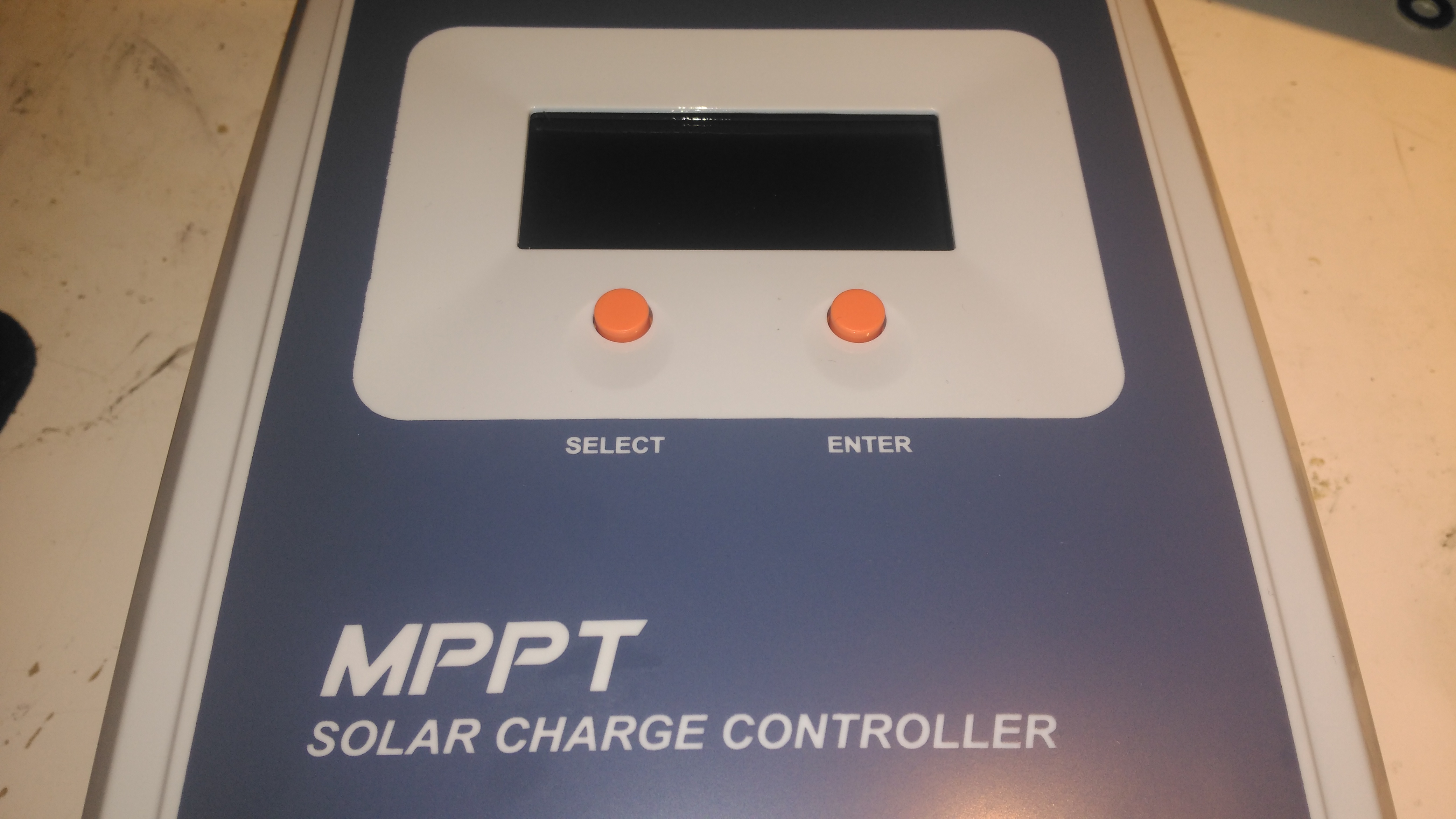
The front panel has a basic LCD, which shows various stats, such as PV Volts & Amps, and battery bank Volts & Amps. The pair of buttons are used to navigate the basic menu to configure some options, along with switching the load terminals ON/OFF.
Specifications
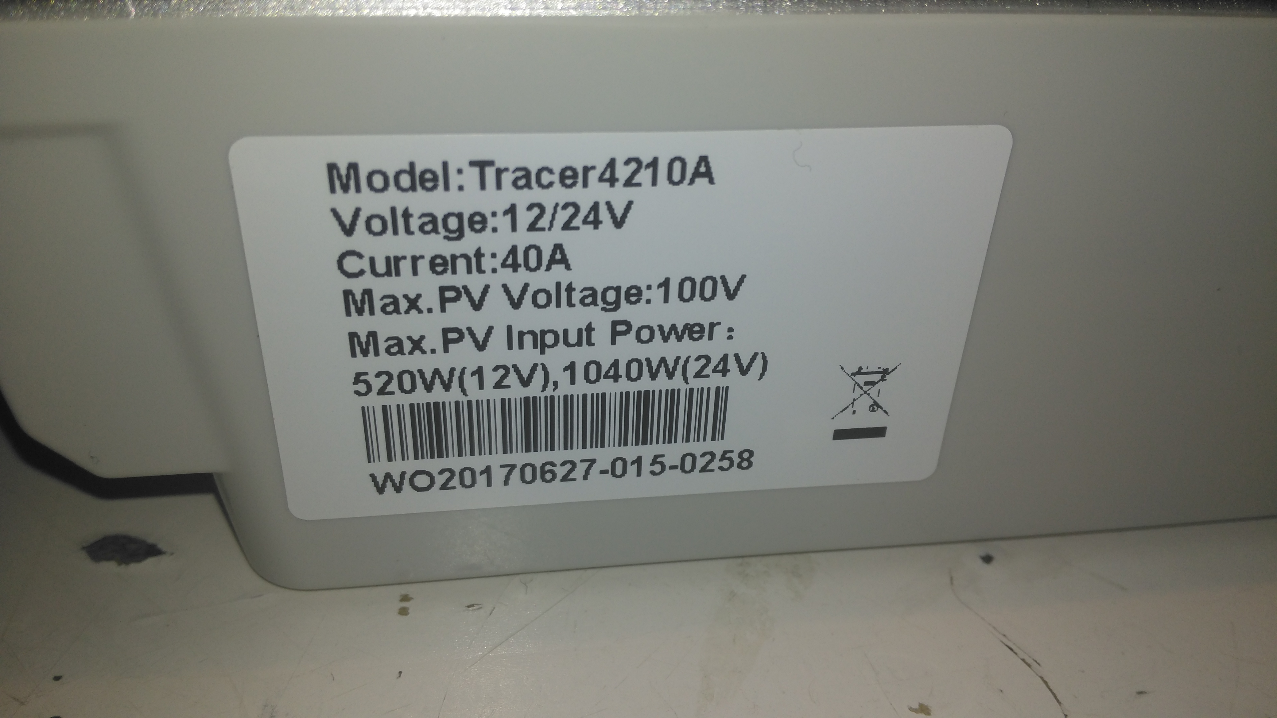
There’s a specs label on the top, with a slight difference here vs the manual, which states the max. PV volts as 92v.
Main PCB Overview
Removing 4 machine screws from the bottom of the unit allows the top to come off. Like the MT50 remote panel, this unit also has moulded-in brass thread inserts in the plastic parts. The PCB in here is heavily comformal coated, which stops me from reading the laser-etched numbers on the semiconductor devices, so there will be few details there.
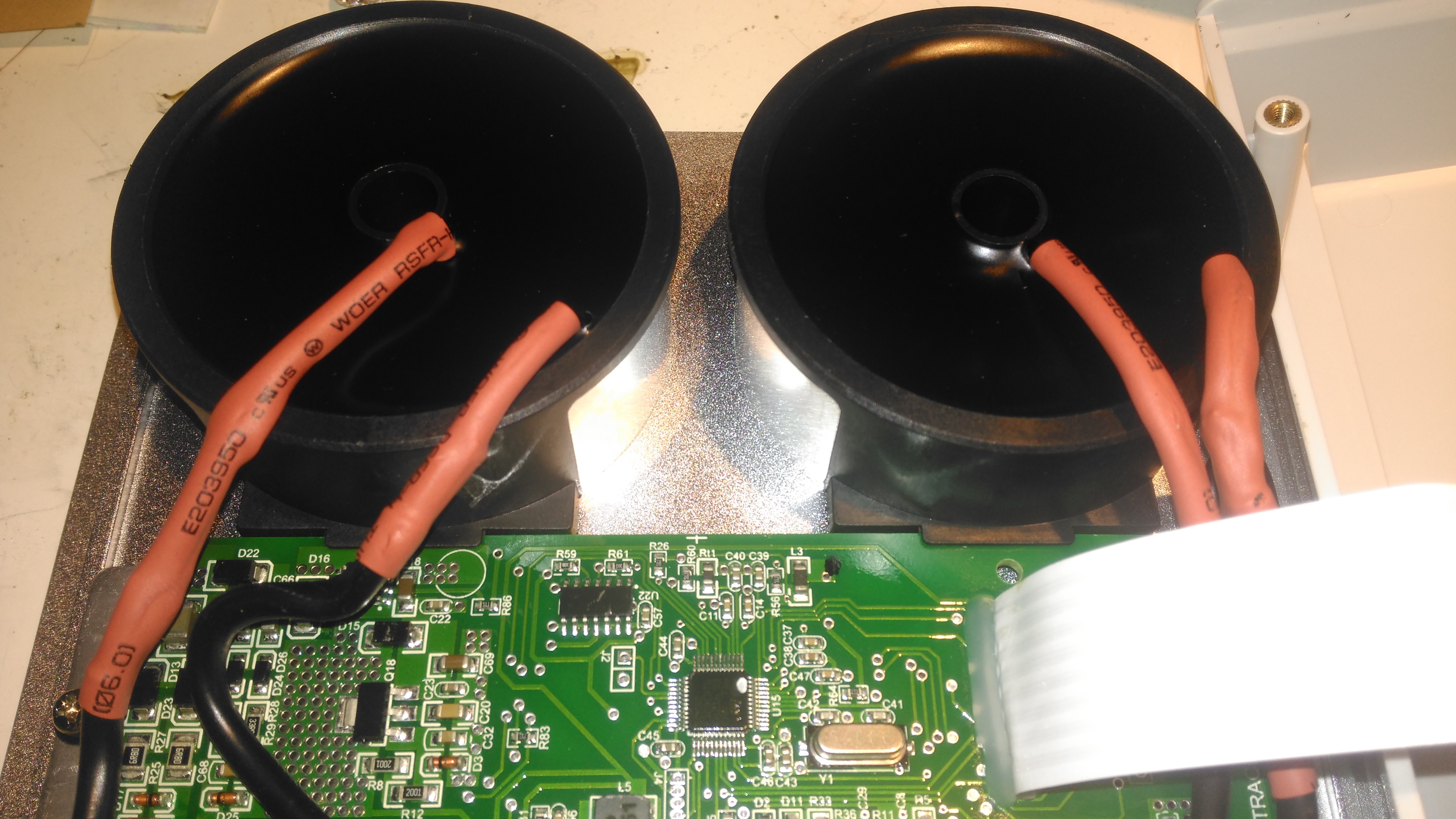
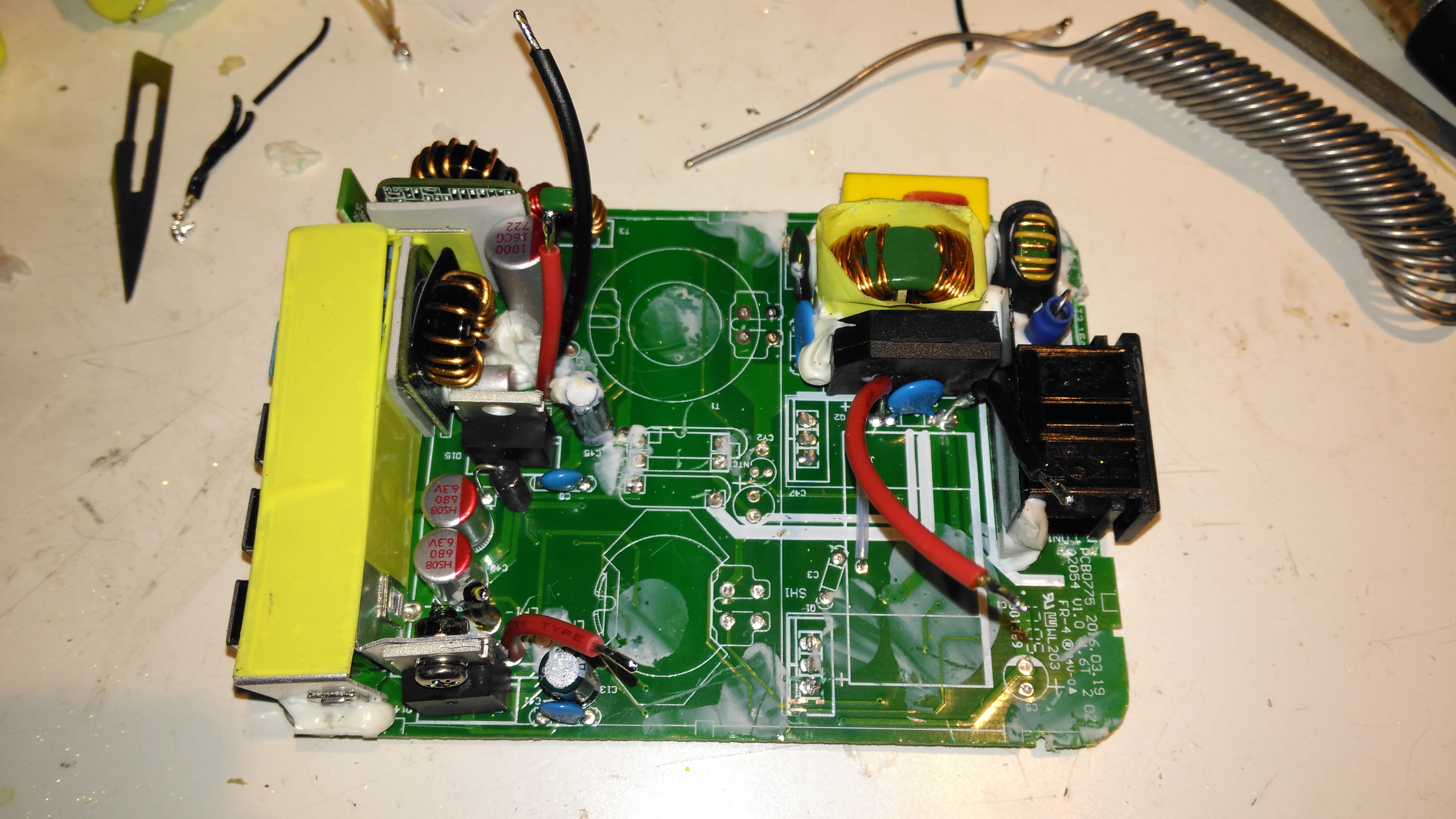
Main PCB Lower
Here’s the bottom section of the main PCB, with the enormous screw terminals, which will easily take cables up to about 16mm². The RJ-45 jack which hosts the unit’s RS-485 bus is to the right, and a smaller 2-pin connector on the left sorts out the battery temperature sensor.
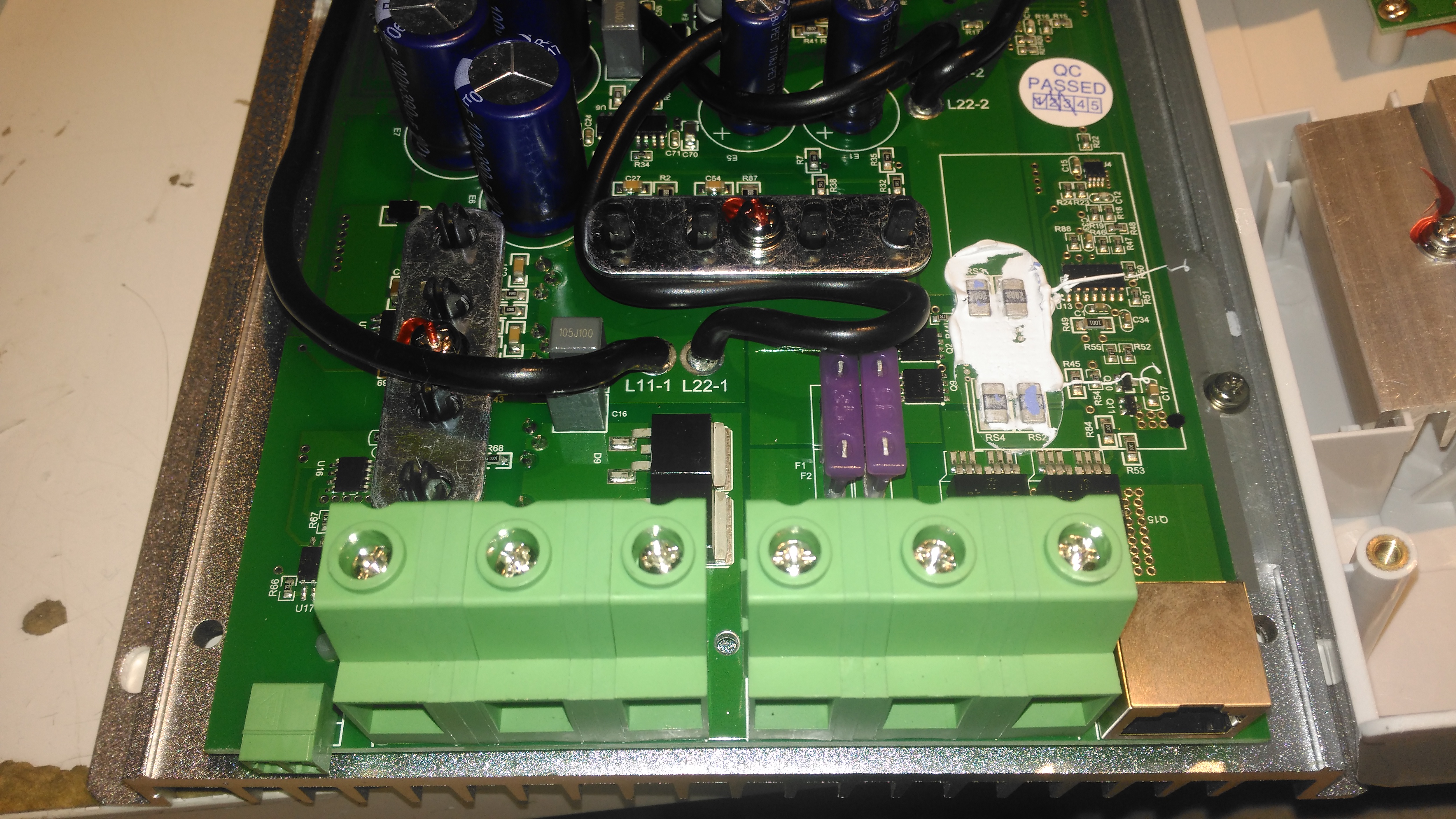
The DC output MOSFET switches are hiding just behind the right-hand terminals, there’s a pair of them in this unit to handle the output current. Some beefy diodes polarity-protect both the battery & PV inputs.
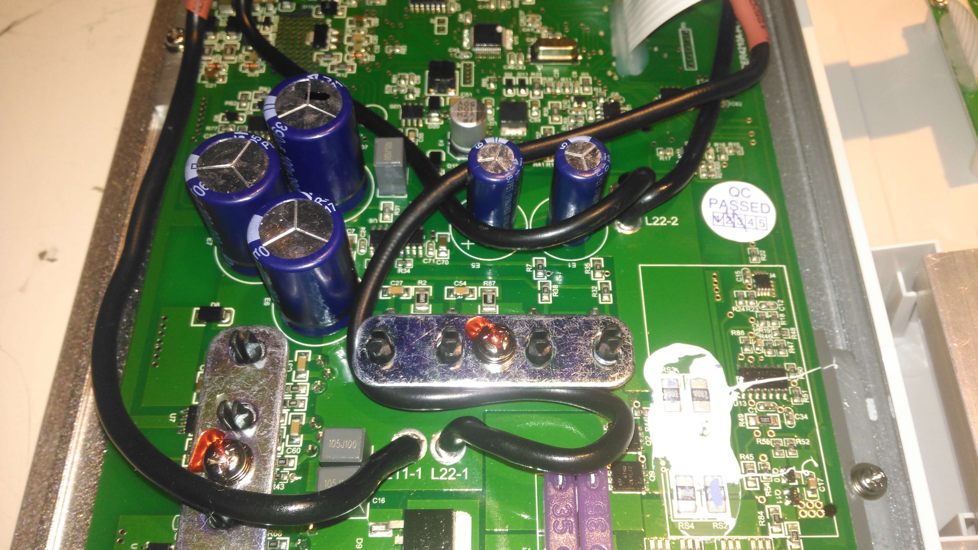
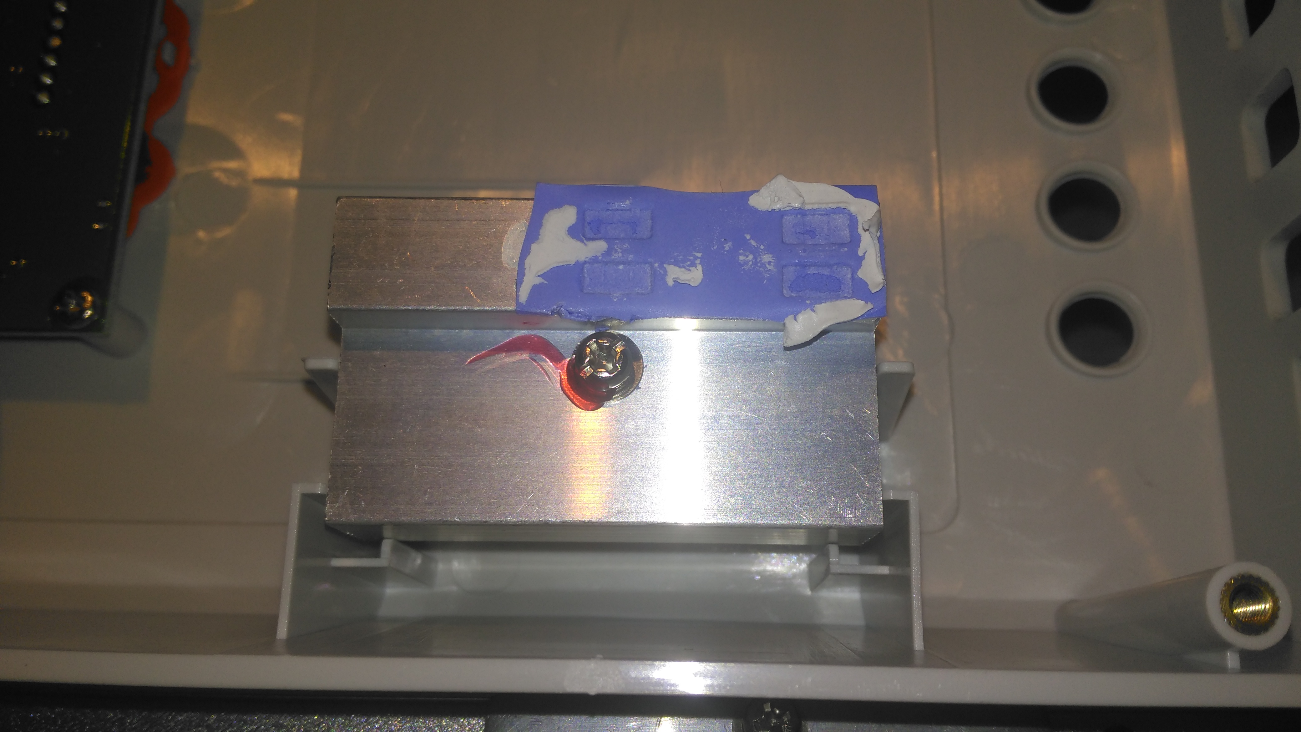
Board Centre
Moving up the board shows two 35A automotive blade fuses soldered into the board – these would be a real pain to replace if they ever blew, however with the electronic load current protection built into this unit, it’s an unlikely situation, unless something went hideously wrong. The main switching devices for the DC-DC converter are hidden – they’re clamped to the heatsink with the bars at right angles in the photo, I’m not going to dig any deeper into this just for those though – they’re just TO220 devices.
Under a load of thermal gunk on the right are 4 current shunt resistors, and the amplifiers for reading their values. These 1206-size SMD resistors looked a bit small for the power rating to me, but they’re heatsinked in operation to a small heatsink mounted in the top cover.
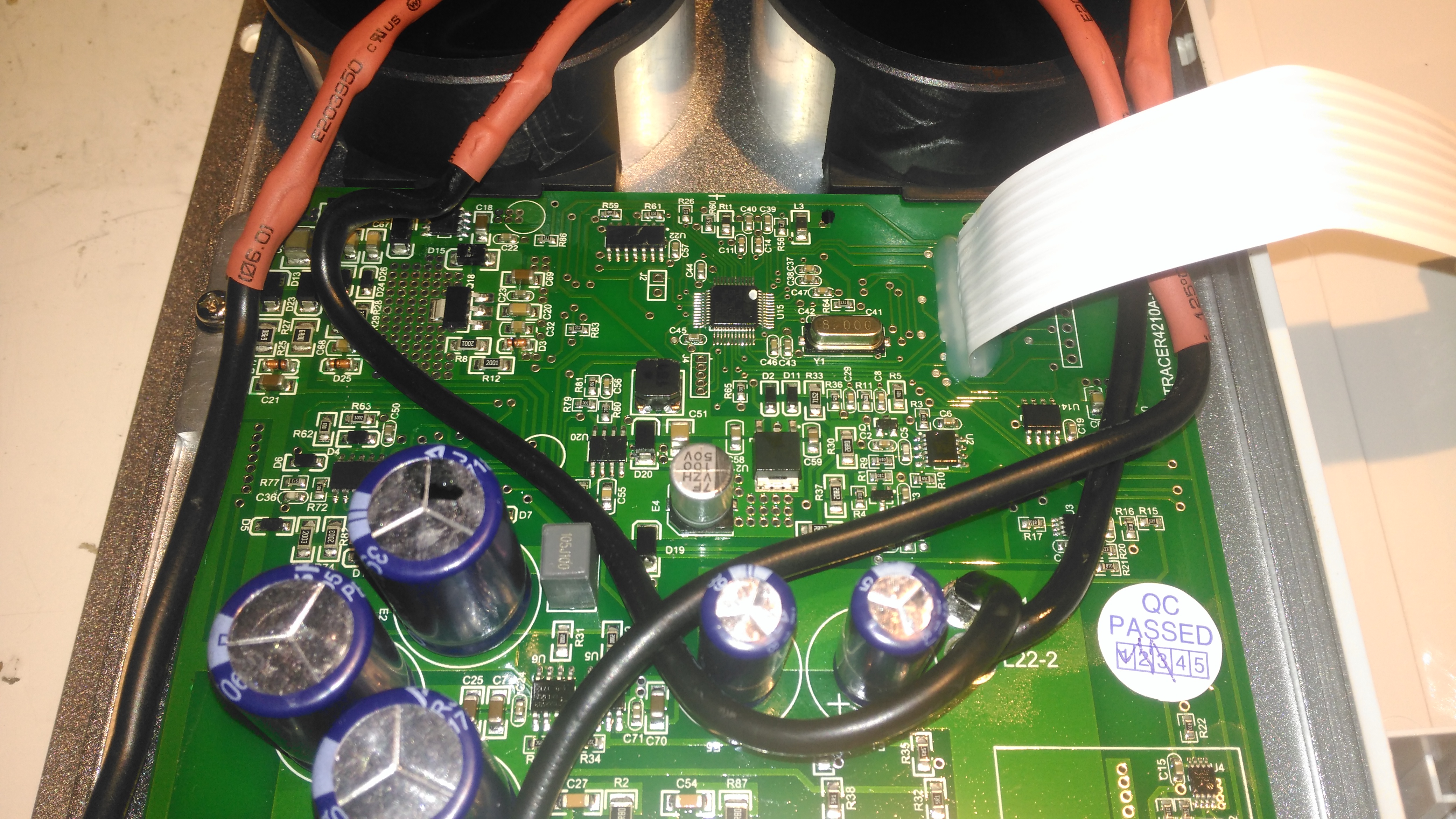
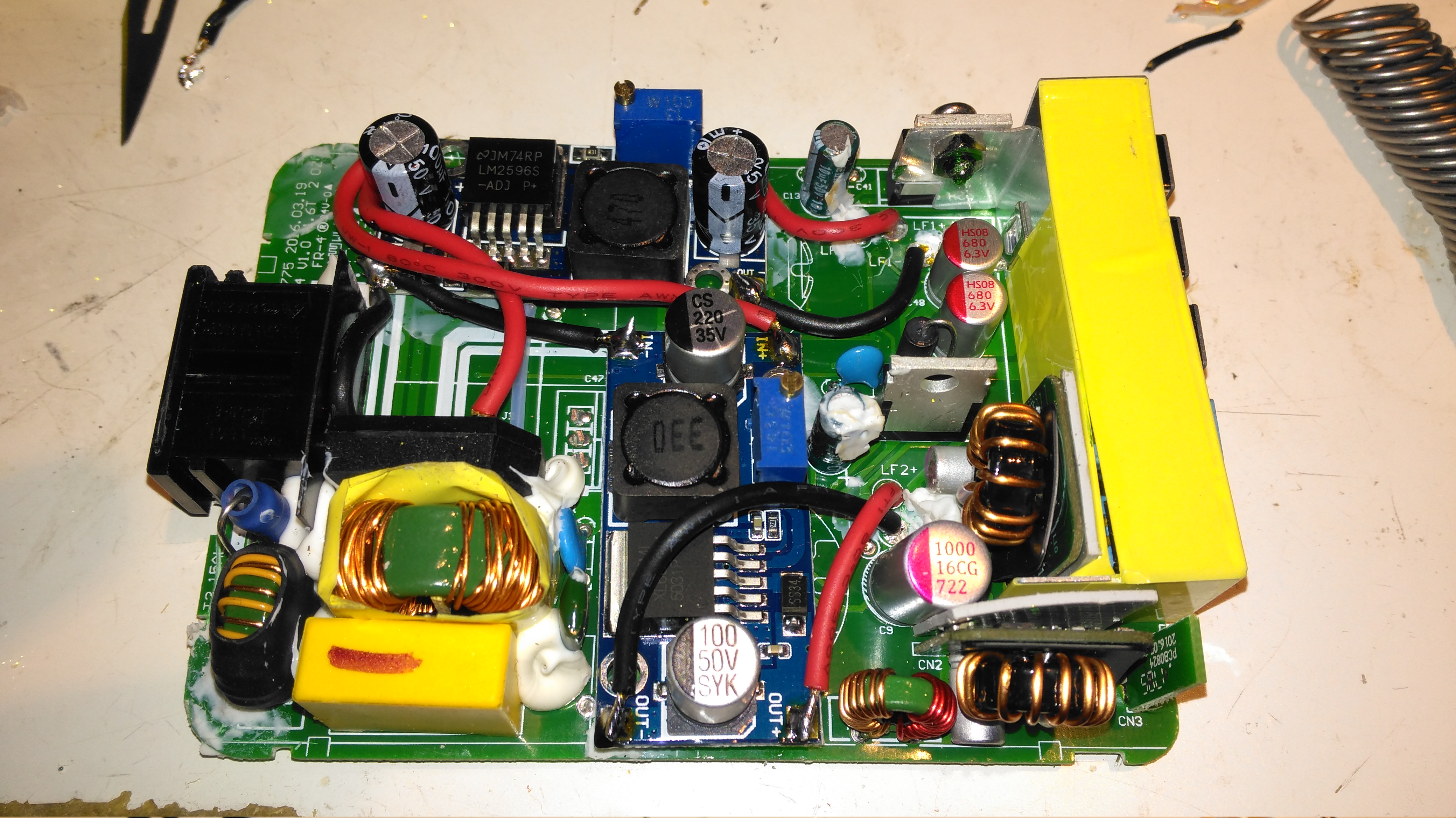
Board Upper
The upper section of the PCB hosts the main microcontroller, and the connections over to the front panel LCD & buttons. Couldn’t really get much info from these chips, due to the conformal coating.
Toroidal Inductors
Right at the top of the unit are these toroidal inductors, potted into aluminium housings. The copper windings of these is very heavy – at least 2.5mm². They’re electrically in parallel, the 20A version would only have a single inductor.
Current Shunt Heatsink
This small heatsink sits inside the top cover, and provides some cooling to the current shunts.
Display Board
Not much to say for the display board, there’s going to be nothing here apart from an I²C LCD driver & the pair of front panel buttons, so I won’t bother removing this from the case.
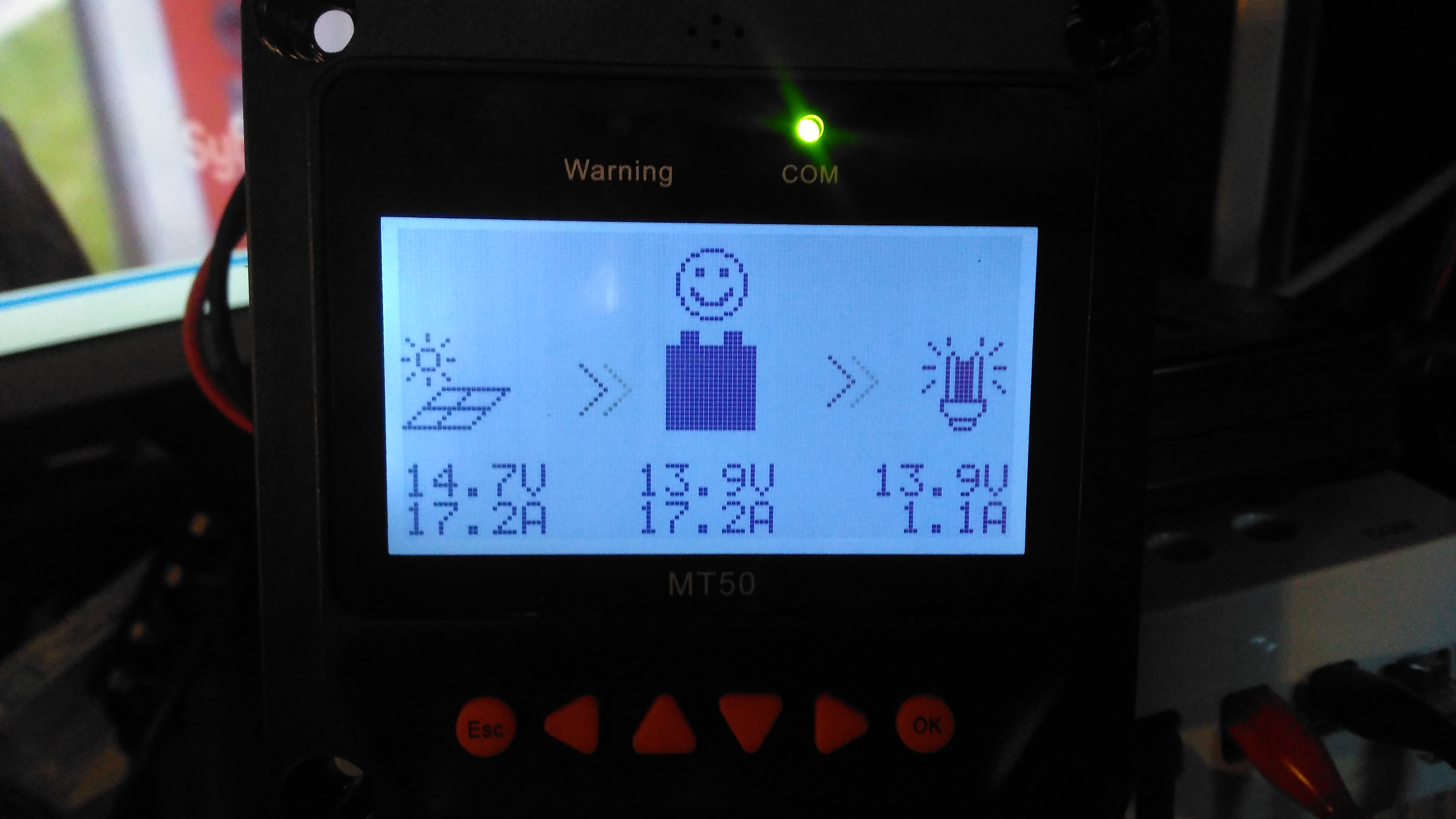
Here’s the MT50 controller from EpEver, that interfaces with it’s Tracer MPPT solar charge controllers, and gives access to more programming options on the charge controllers, without the need for a laptop. The display is a large dot-matrix unit, with built in backlight. Above is the display on the default page, showing power information for the entire system.
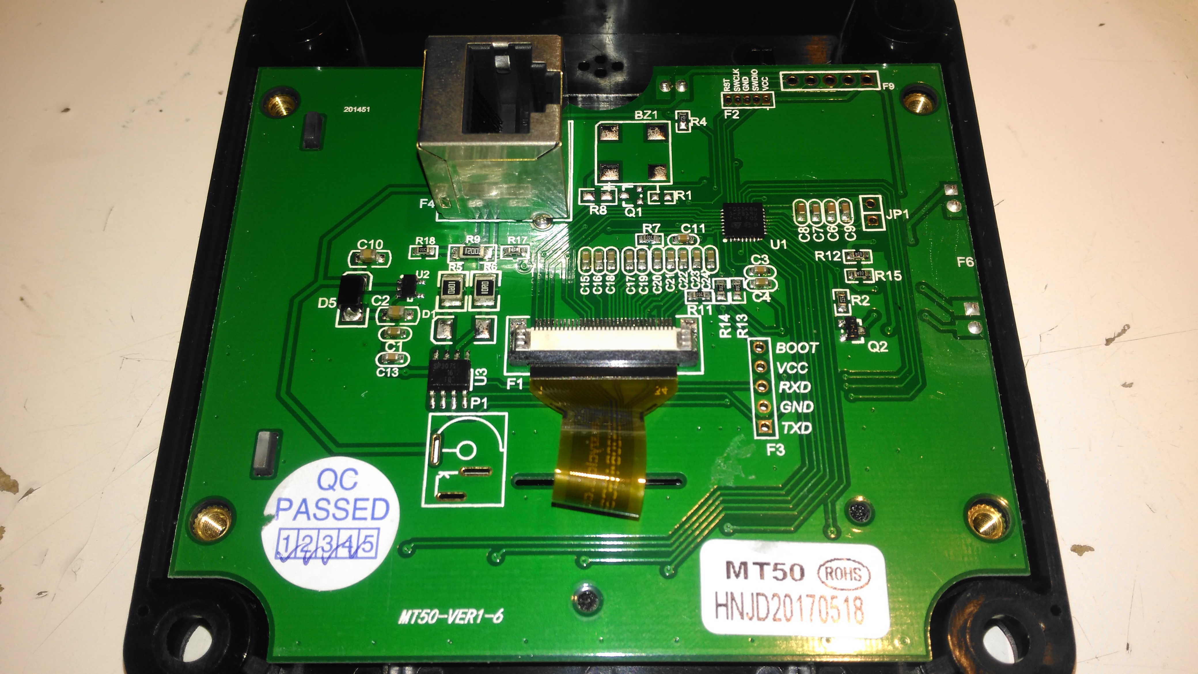
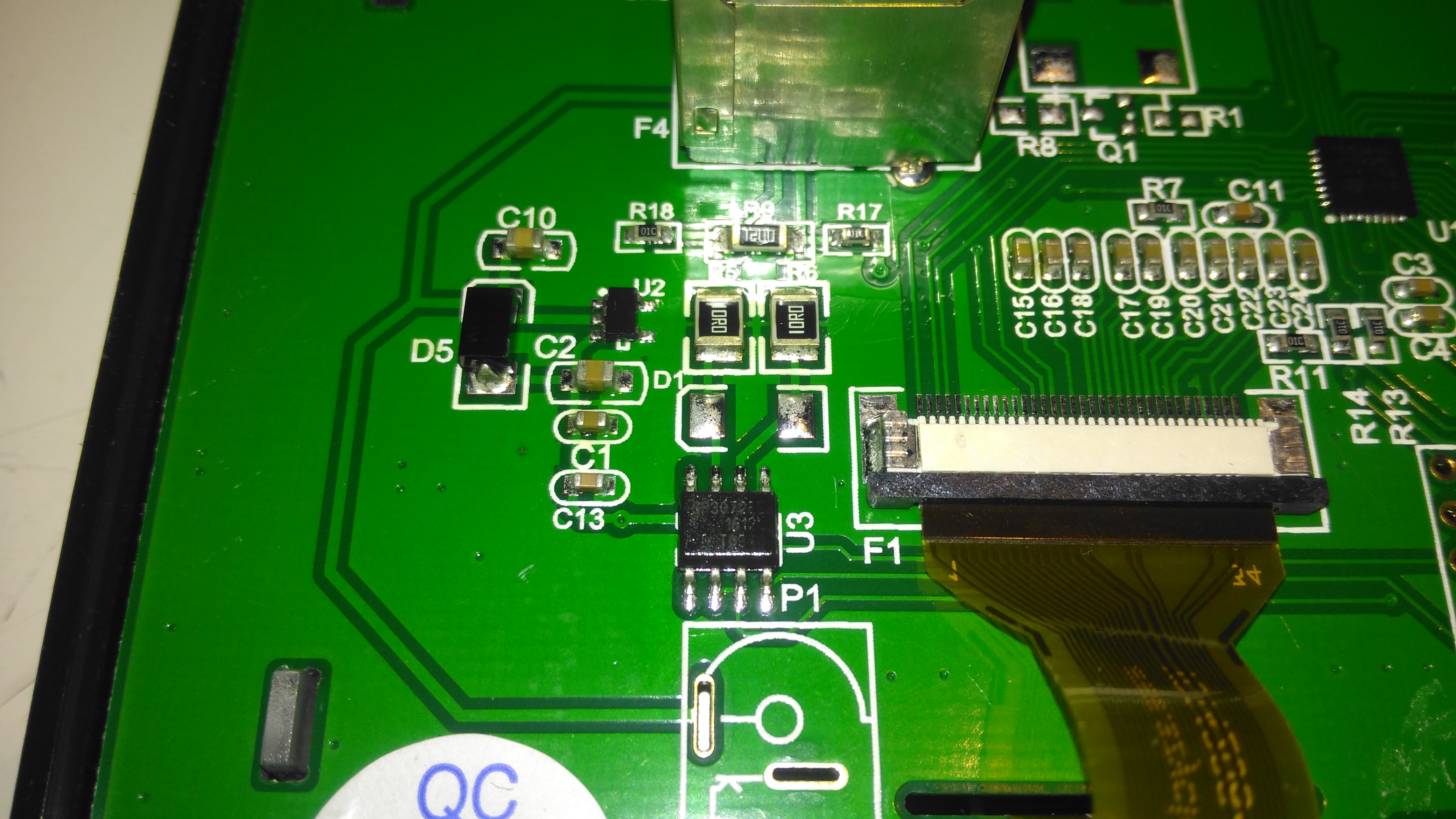
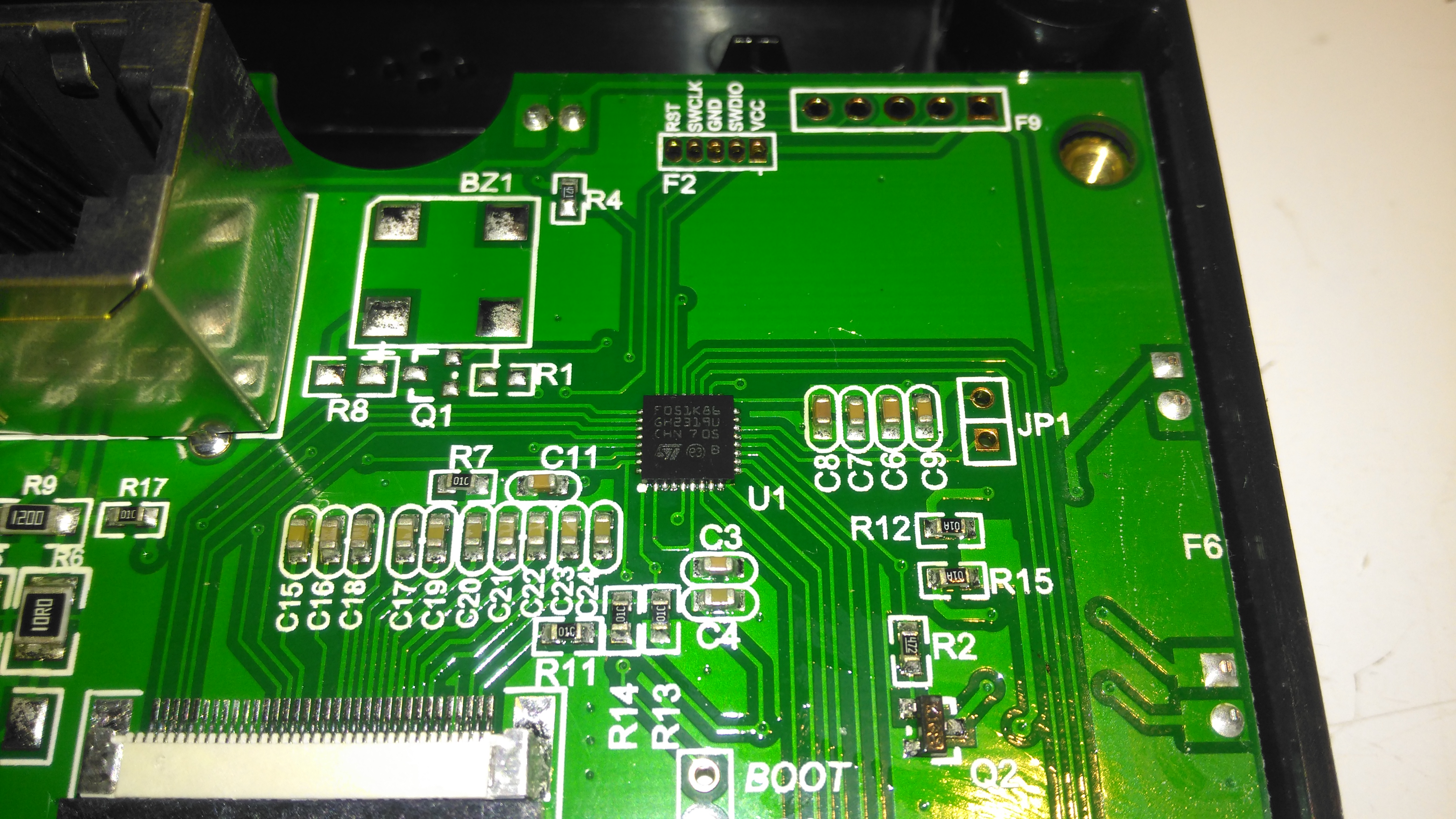
PCB Rear
The rear plastic cover is held in place by 4 machine screws, which thread into brass inserts in the plastic frame – nice high quality touch on the design here, no cheap self tapping plastic screws. Both power & data arrive via an Ethernet cable, but the communication here is RS-485, and not compatible with Ethernet! The PCB is pretty sparse, with comms & power on the left, LCD connection in the centre, and the microcontroller on the right.
RS-485 Transceiver
On the left of the board is the RS0485 transceiver, and a small voltage regulator. There’s also a spot for a DC barrel jack, which isn’t included in this model for local power supply.
STM32 Microcontroller
The other side of the board holds the main microcontroller which communicates with the charge controller. This is a STM32F051K8 from ST Microelectronics. With a 48MHz ARM Cortex M0 core, and up to 64K of flash, this is a pretty powerful MCU that has very little to do in this application.
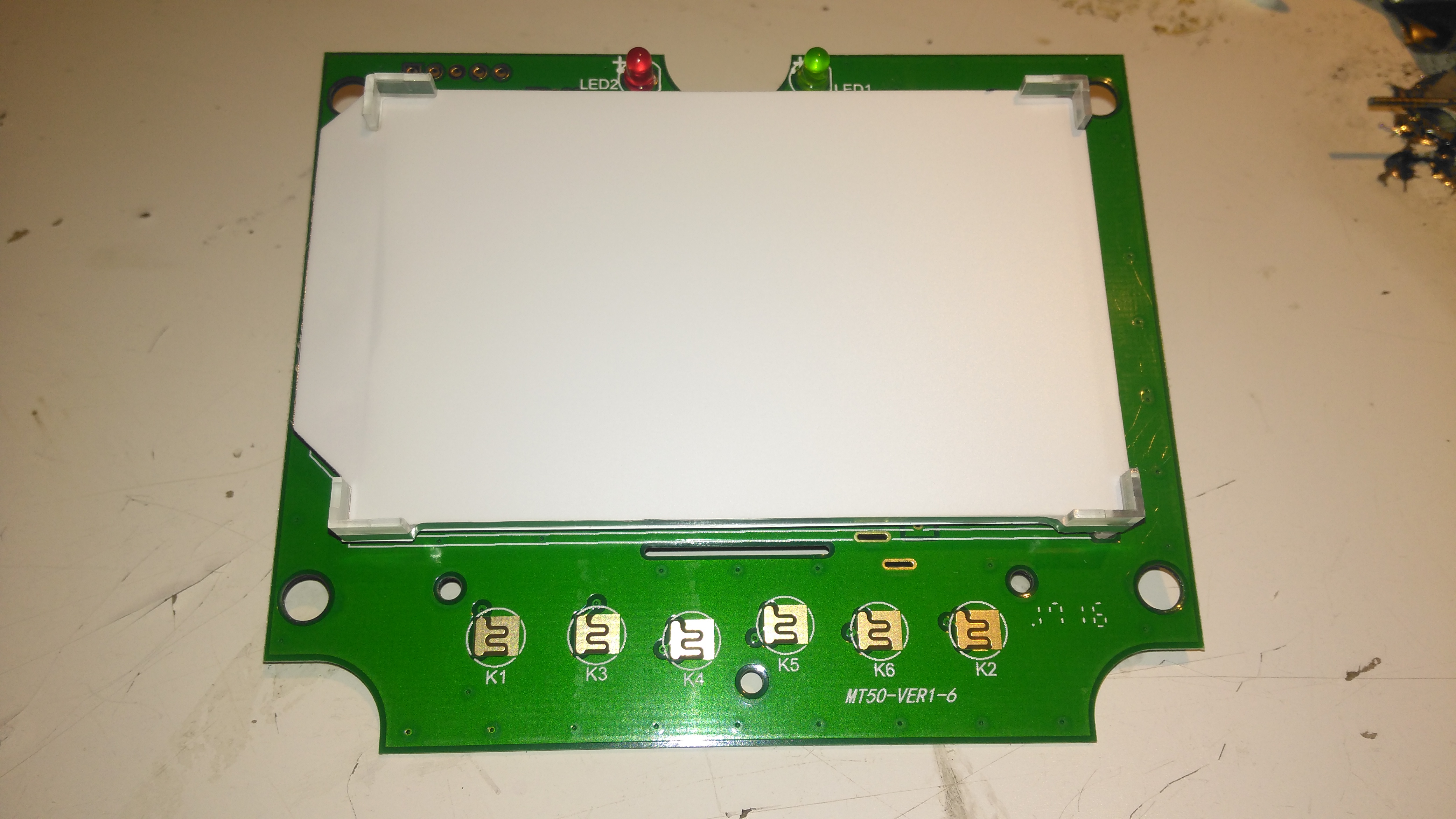
PCB Front
The front of the PCB has the ENIG contacts of the front panel buttons, and the LCD backlight assembly. There’s nothing else under the plastic backlight spreader either.
LCD Rear
The front case holds the LCD module in place with glue, and the rubber buttons are placed underneath, which is heat staked in place.
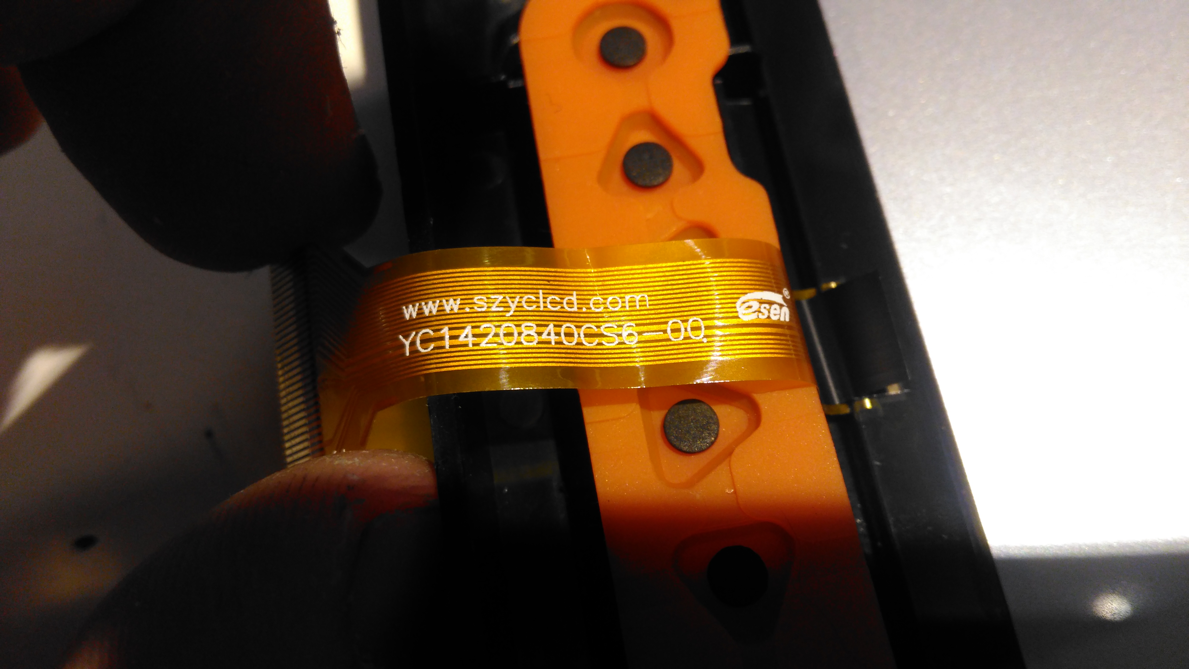
LCD Model
The LCD is a YC1420840CS6 from eCen in China. Couldn’t find much out about this specific LCD.
On my home network I have a system running PiHole – a DNS server that blocks all unwanted traffic, such as ads. Since I have an official Pi LCD with a broken touch panel, I decided to use the bare LCD as a status display for PiHole.
This requires some extra packages installing onto the base system after PiHole is installed & configured, and the interface automatically starts on bootup. I used the latest Raspbian Jessie Minimal image for this system, and ran everything over a SSH connection.
First thing, get the required packages installed onto the Pi:
Once these are installed, it’s time to configure the startup script for Midori to display the status page. Create StartMidori.sh in /home/pi and fill with the following:
#!/bin/sh export DISPLAY=:0
xset -dpms
xset s off
xset s noblank
unclutter &
matchbox-window-manager &
midori -e Fullscreen -a http://127.0.0.1/admin/
This script disables all power management on the system to keep the LCD on, starts unclutter to hide the mouse pointer and finally starts the Matchbox Window Manager to run Midori, which itself is set to fullscreen mode, and the URL of the admin panel is provided.
The next step is to test, give the script executable permissions, and run the script:
Once this is run, the LCD should come to life after a short delay with the PiHole stats screen. Close the test & return to the terminal by hitting CTRL+C.
Now the Pi can be configured to autorun this script on boot, the first thing to do here is to enable autologin on the console. This can be done with raspi-config, select Option 3 (Boot Options), then Option B1 (Desktop/CLI), then Option B2 (Console Autologin). When prompted to reboot, select No, as we’ll be finishing off the config before we reboot the system.
The next file to edit is /etc/rc.local, add the command to start the status browser up:
#!/bin/sh -e
#
# rc.local
#
# This script is executed at the end of each multiuser runlevel.
# Make sure that the script will "exit 0" on success or any other
# value on error.
#
# In order to enable or disable this script just change the execution
# bits.
#
# By default this script does nothing.

# Print the IP address
_IP=$(hostname -I) || true
if [ "$_IP" ]; then
  printf "My IP address is %s\n" "$_IP"
fi
sudo xinit /home/pi/StartMidori.sh &
exit 0
Here I’ve added in the command just above “exit 0”. This will start the browser as the last thing on bootup. The Pi can now be rebooted, and the status display should start on boot!
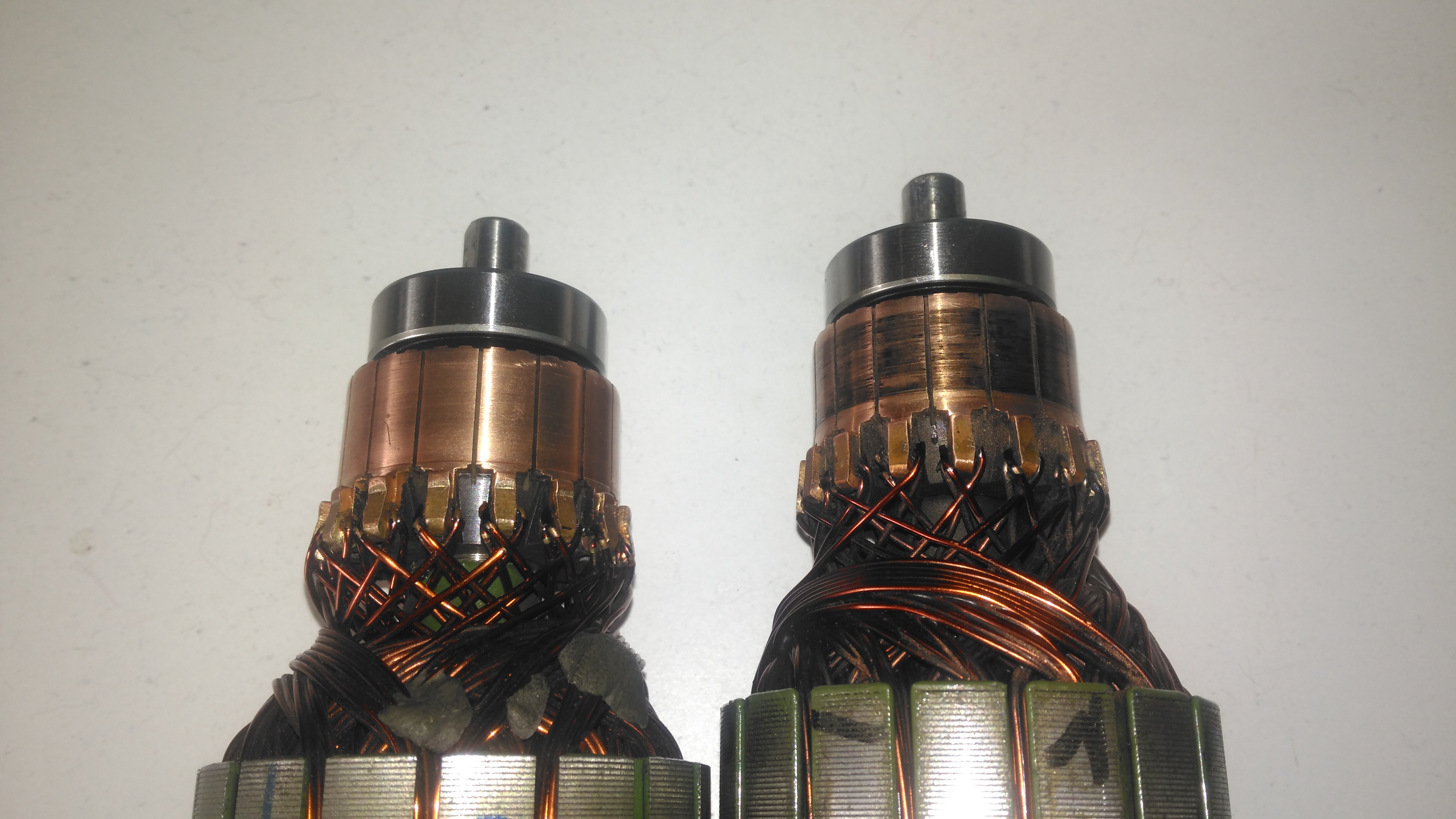
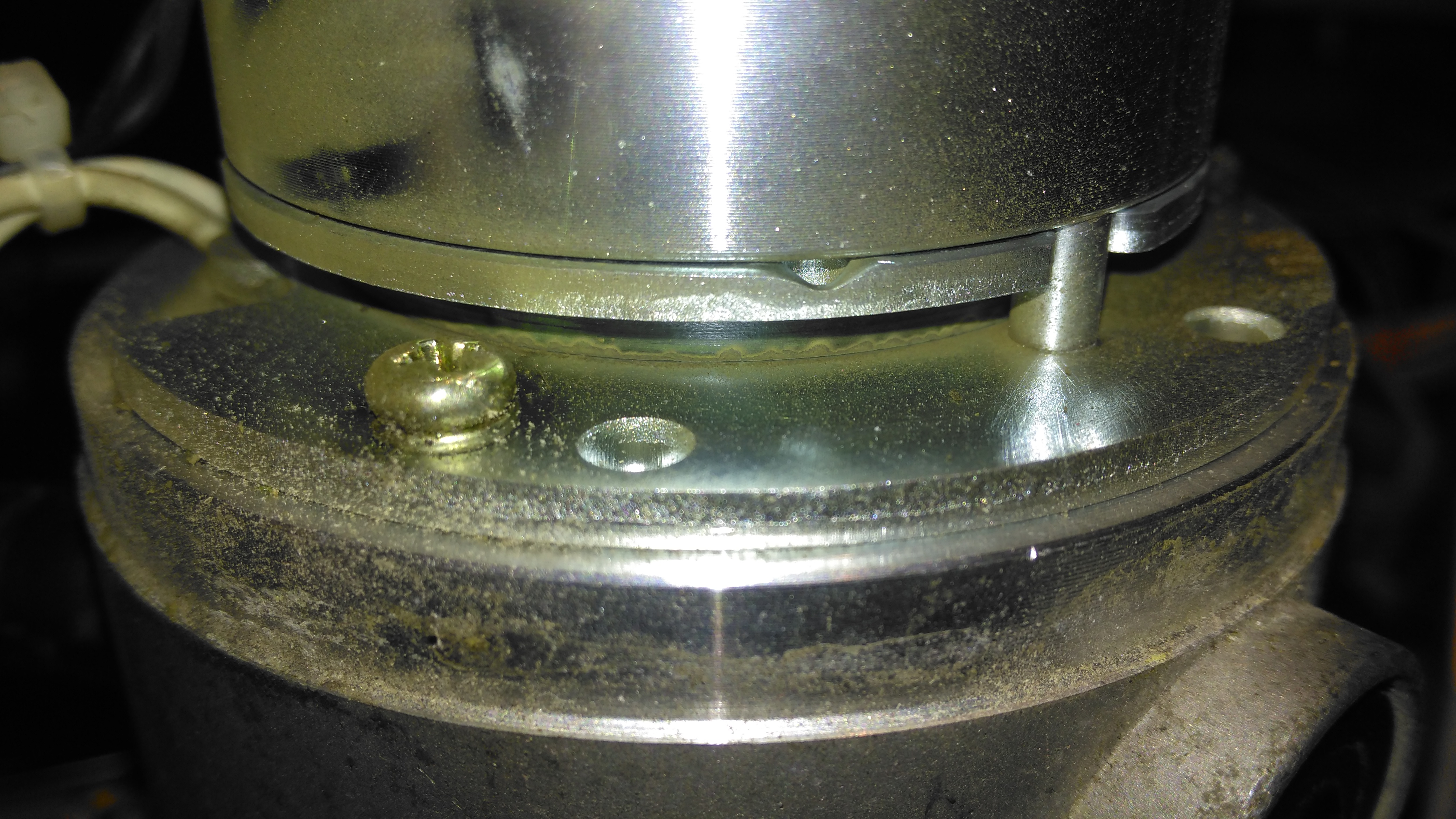
So it’s time to get the propulsion system underway for the trolley, a pair of wheelchair motors were sourced for this, from HacMan. Since I don’t know how many hours are on these units, or how they’ve been treated in the past, I’m going to do a full service on them to ensure reliability. I decided on wheelchair motors due to their extreme ruggedness & heavily built components – this project when complete is going to weigh in at about 150kg!
I suspected something was amiss with one of the motors from running them under no load: the left hand wheelchair motor was heating up to the point of being too hot to touch, so this one at the very least needed some investigation.
Motor Disassembly & Assessment
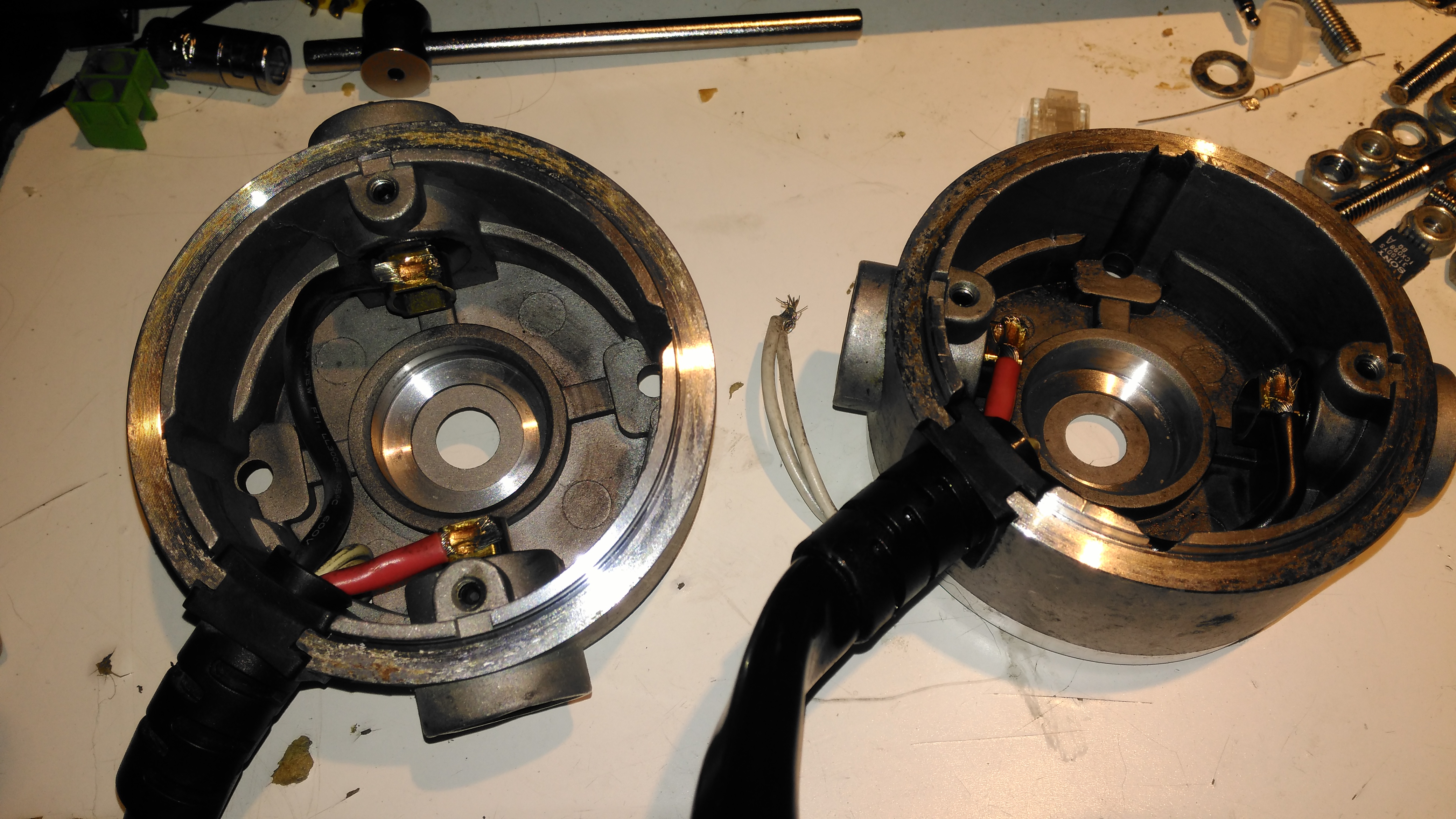
Rear Cover Removed
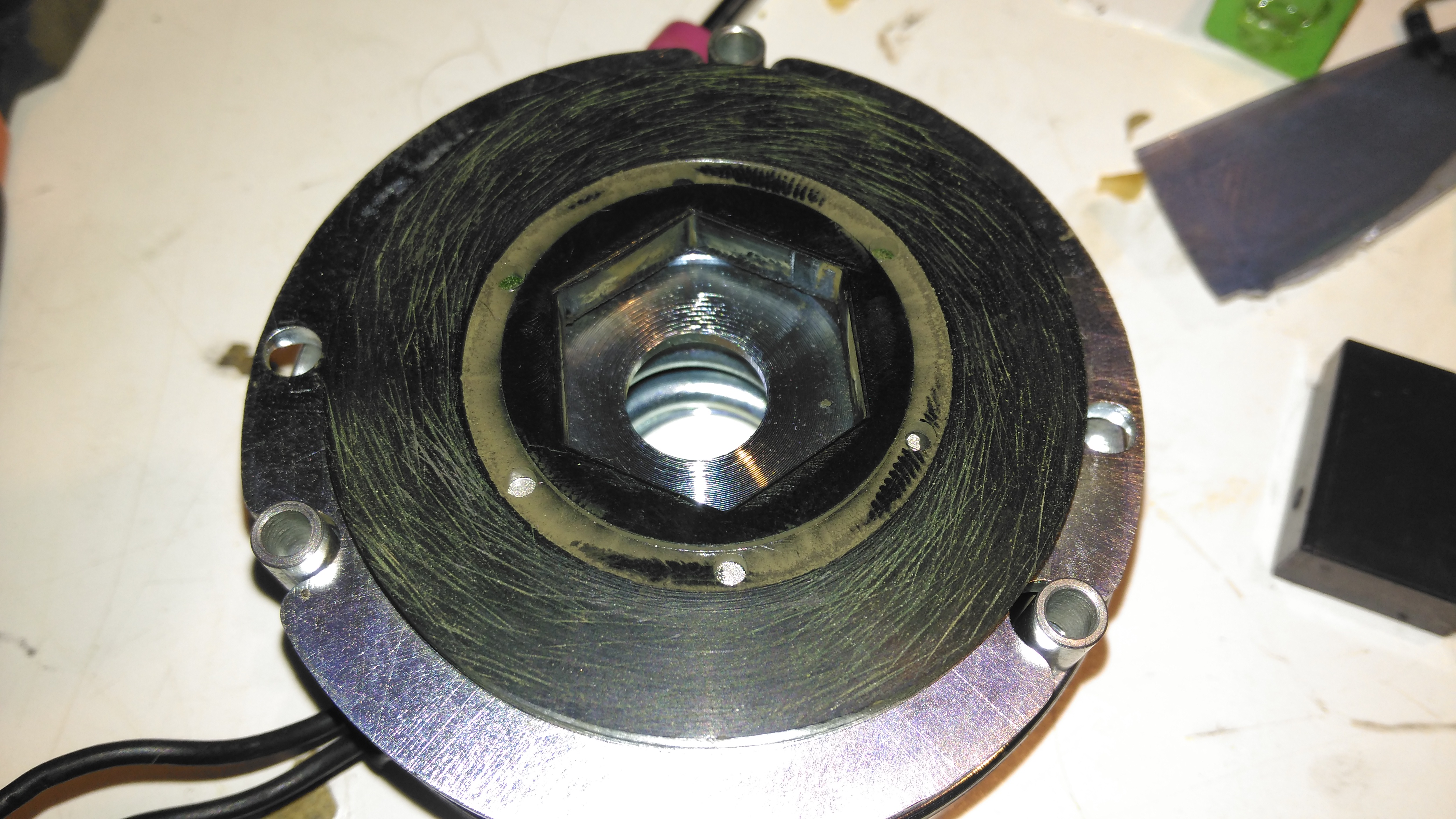
With the back cover removed from the motor the electromagnetic brake is revealed. This engages when power is removed to stop the motor freewheeling, which even though it’s a wormdrive box, it will do readily if backdriven.
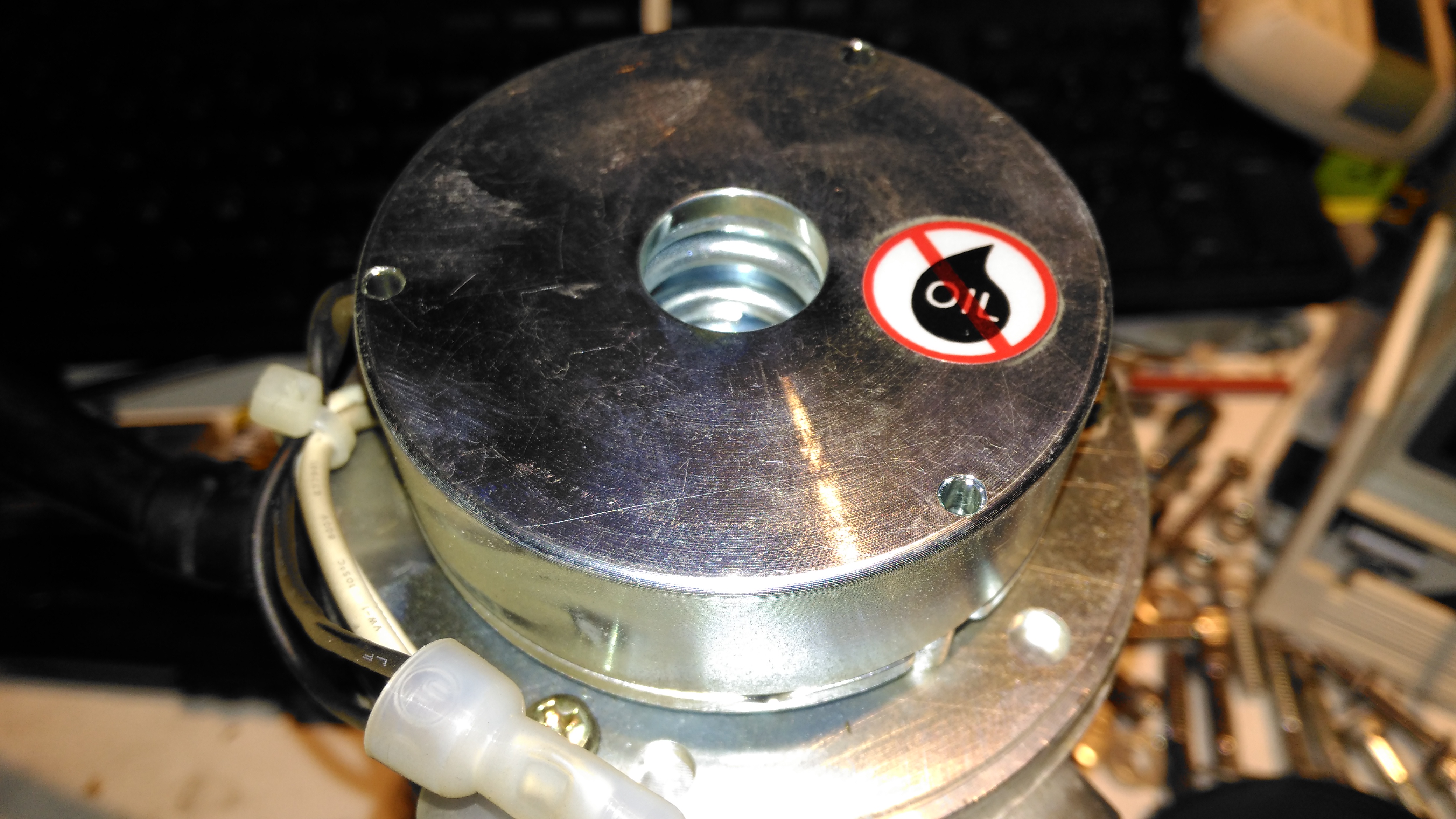
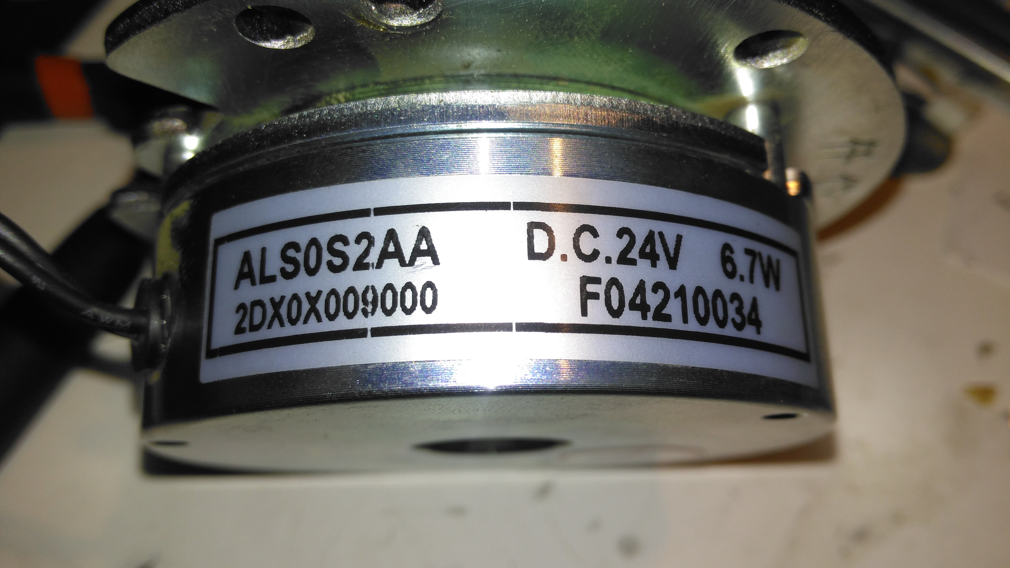
Electromagnetic Brake Assembly
The brake is rated 6.7W at 24v DC.
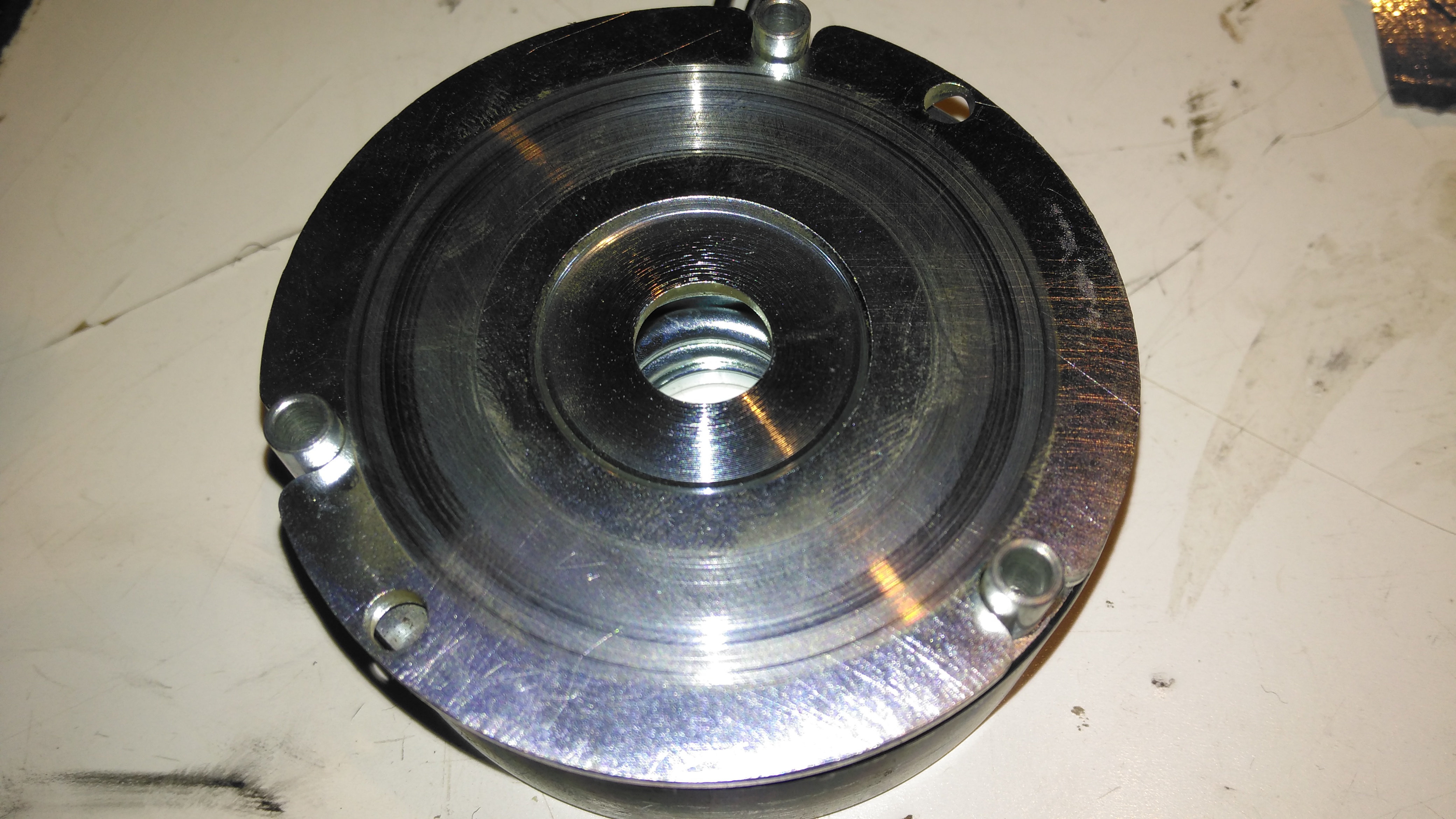
Brake Disc
The brake disc is just visible between the plates of the brake here, with some green dust worn off the disc. When power is applied, the top disc, just under the magnet on top, is pulled upward against spring pressure away from the brake disc, which is attached to the motor armature.
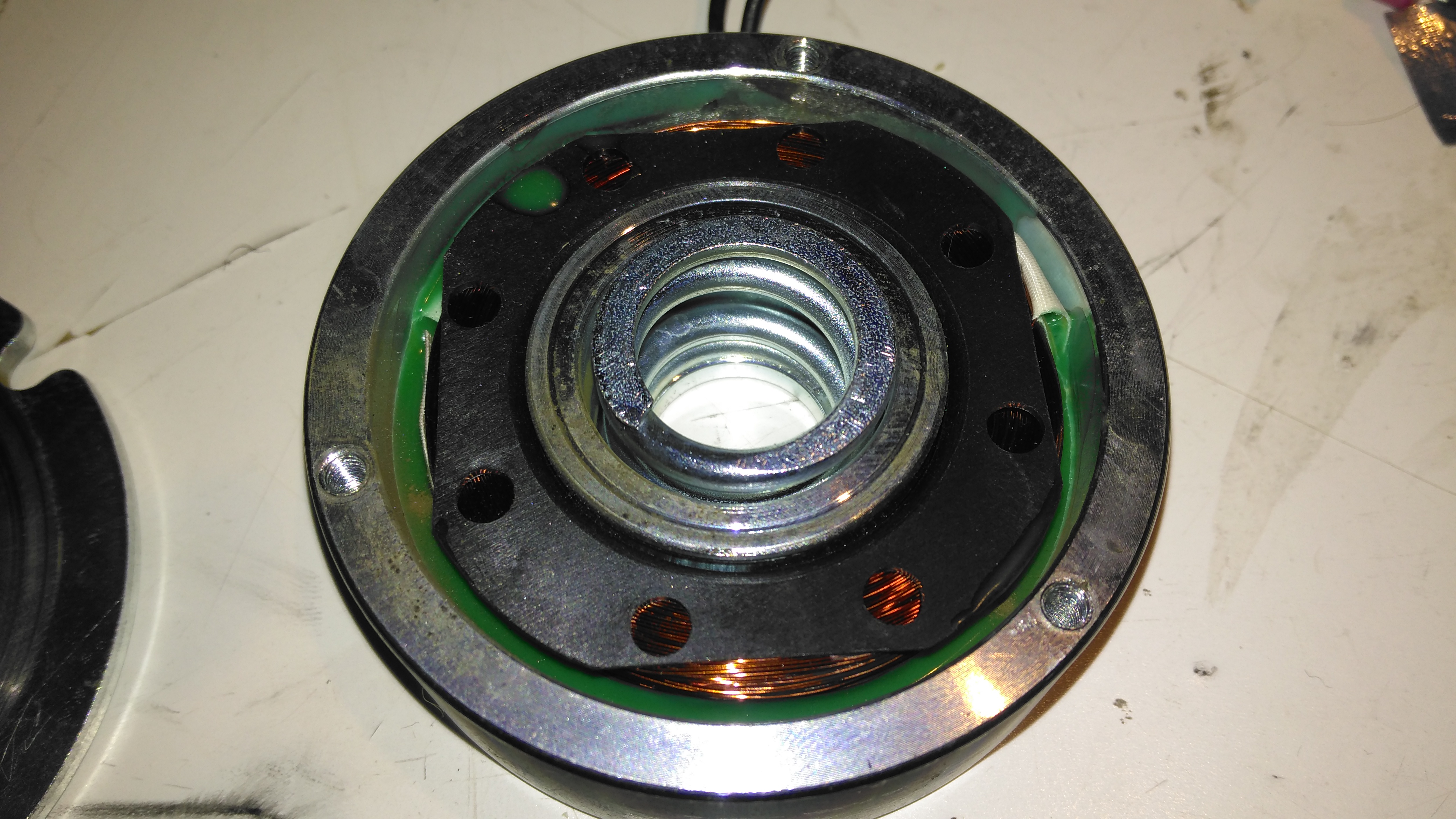
Brake Disc
Here’s the brake disc, removed from the motor. There’s only a little wear here, as I’d expect – these brakes don’t engage until the motors have come to a complete stop.
Brake Actuator
The steel disc above the magnet acts as one of the friction surfaces of the brake.
Brake Solenoid
Finally, the solenoid is at the back, partially potted in resin. The strong coil spring in the centre applies the brakes when power is disconnected.
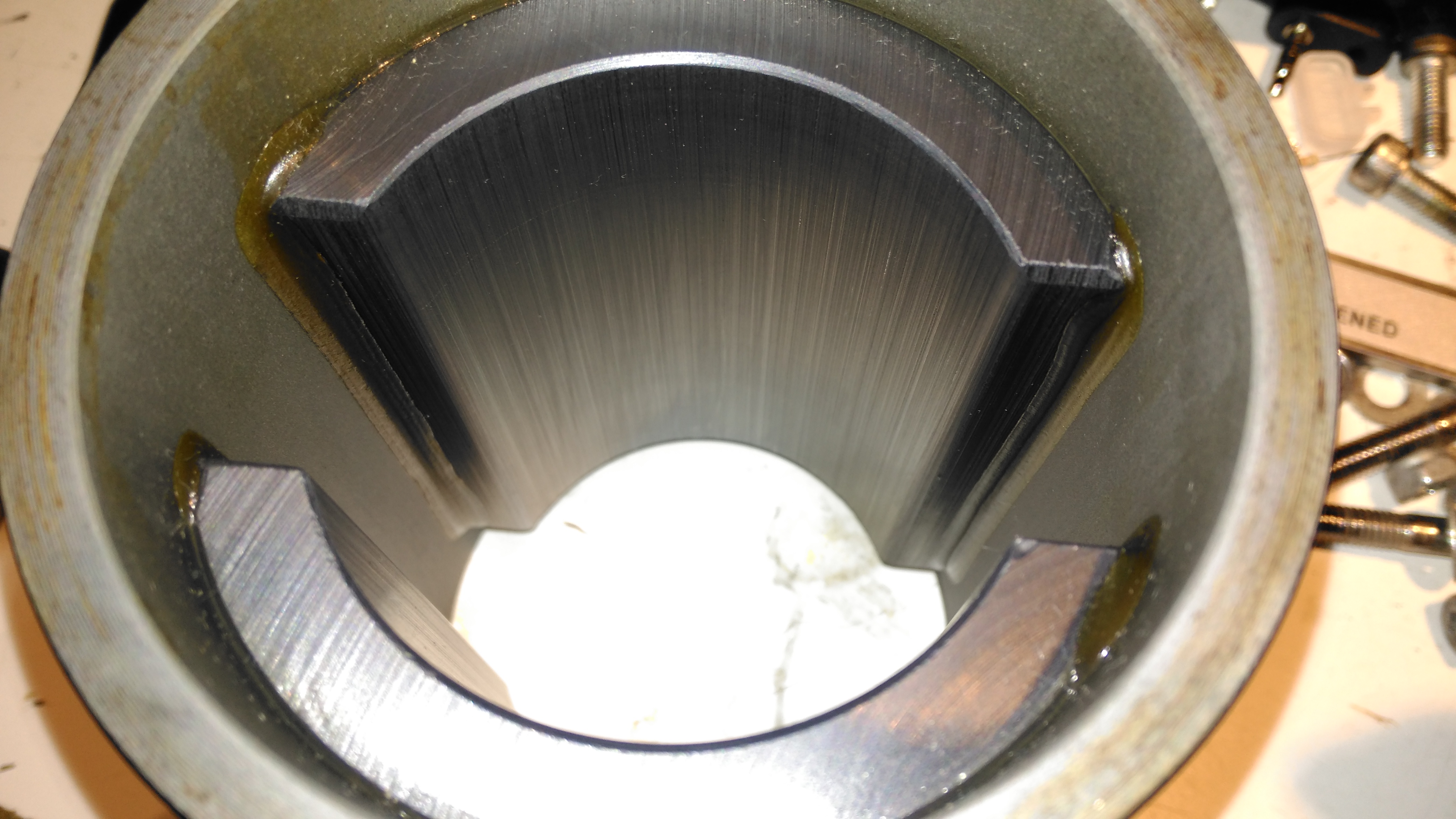
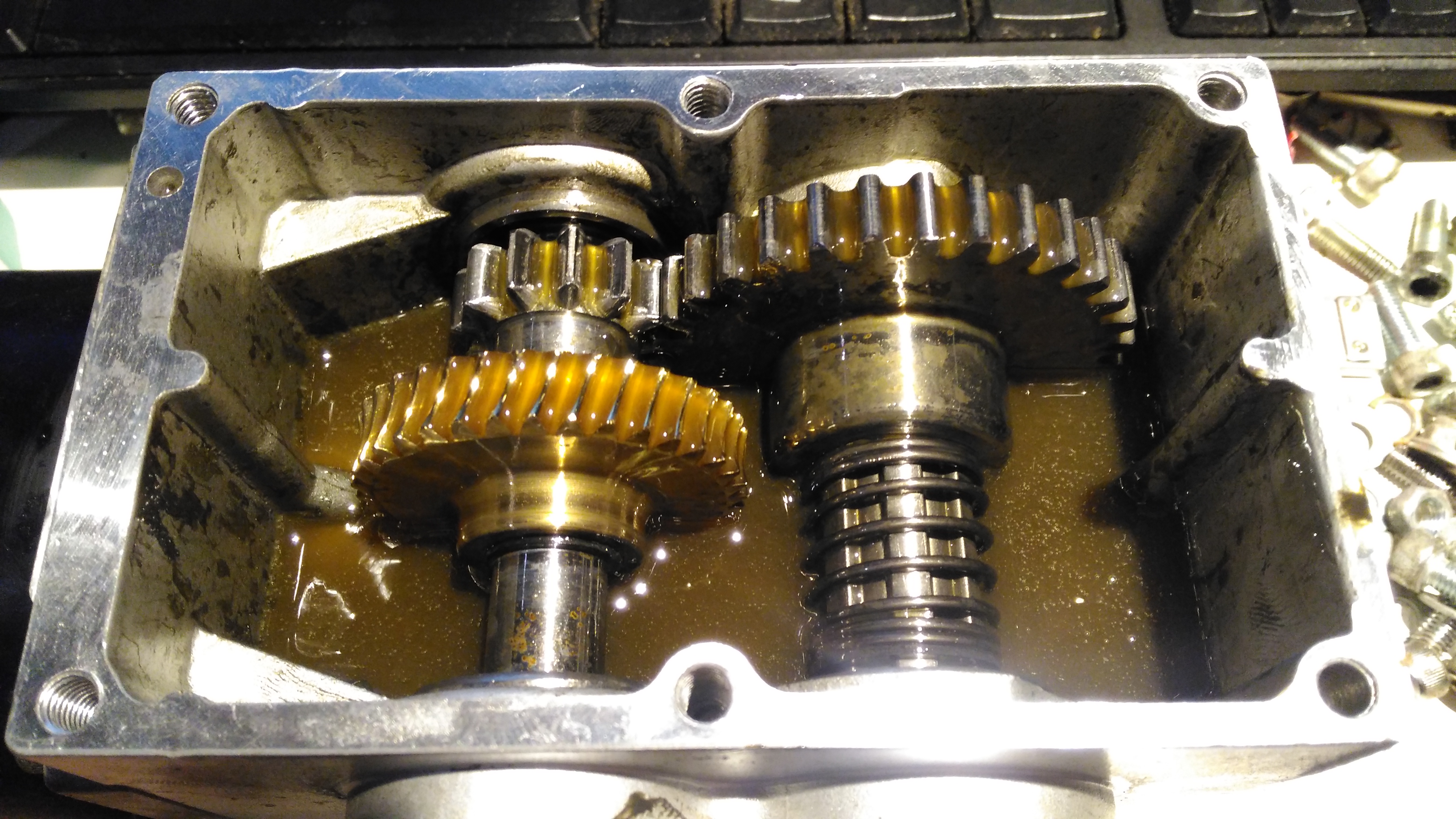
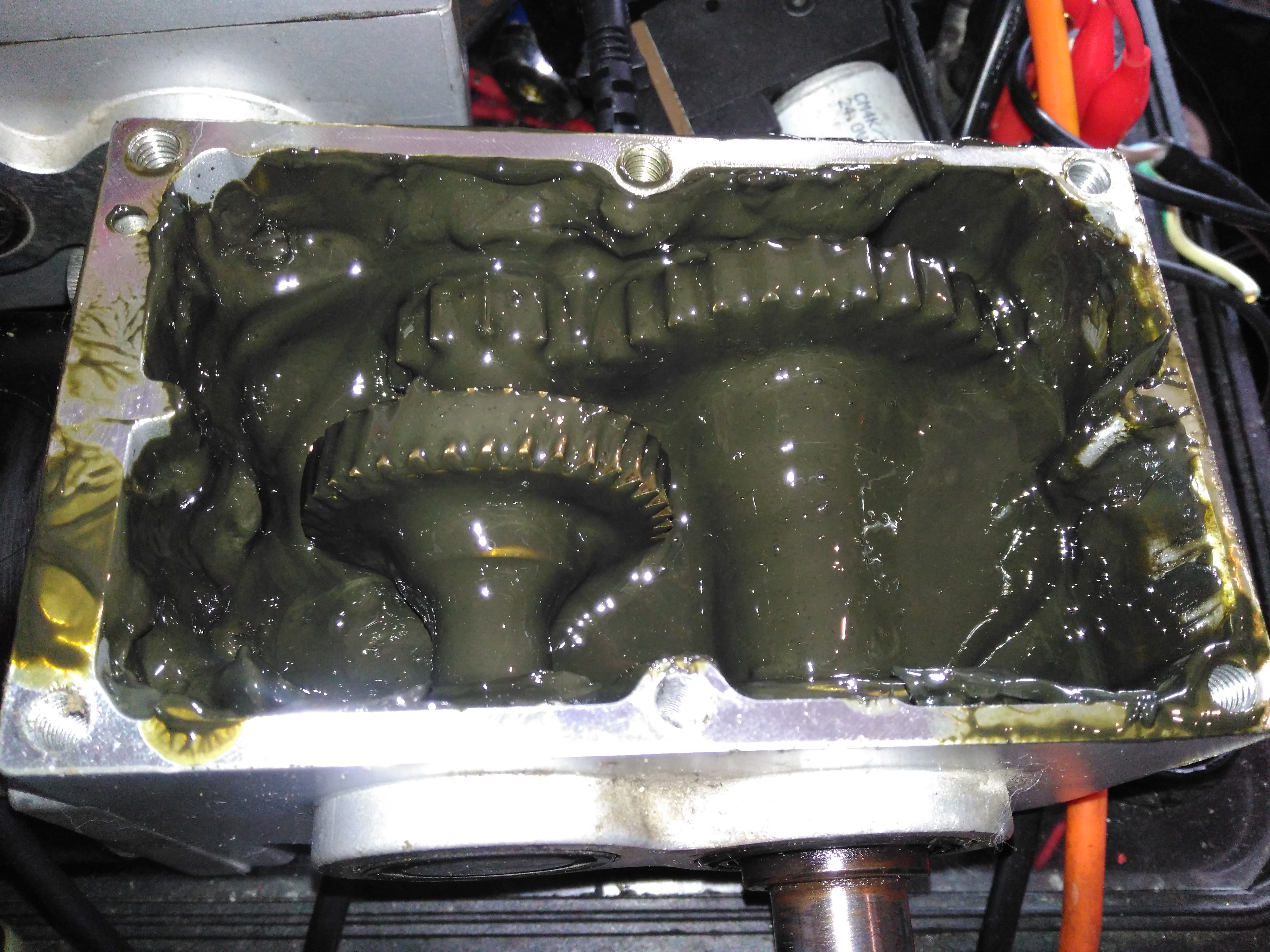
Gearbox Grok
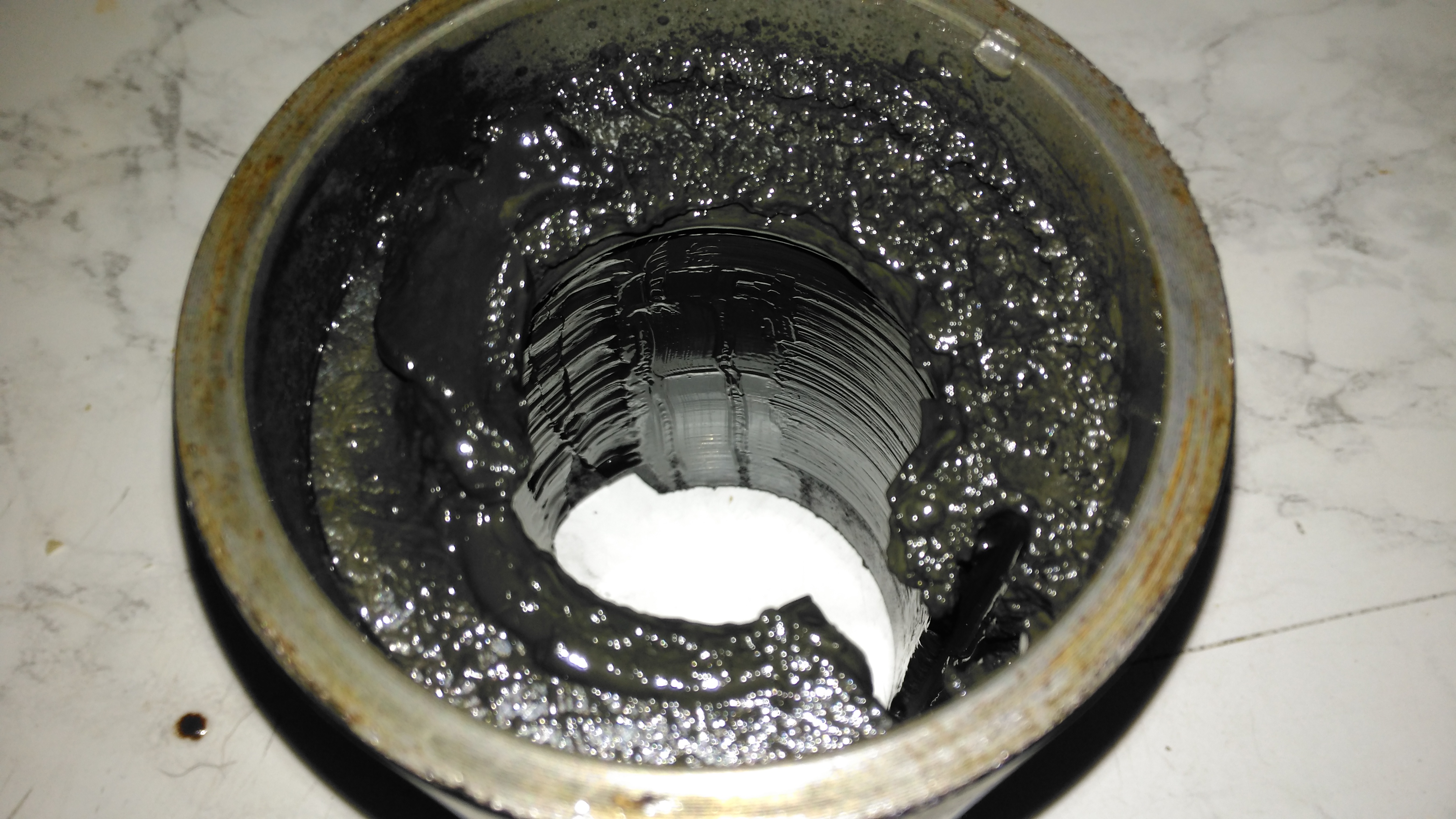
Removing the top of the gearbox reveals the state of the internals – There’s no wear at all on the gearset, but the lubricant is totally manky. The external oil seals have been leaking for some time, letting water in and grease out. The emulsified result is revolting! These gearboxes have a wormdrive first stage, the worm gear is underneath the left hand gearset. Steel spur gears then do the final gearing to the output shaft. The output gear is splined onto the output, and can slide along the shaft out of mesh – this is the freewheel clutch mechanism. At the moment it’s all obscured by the disgusting lubricant.
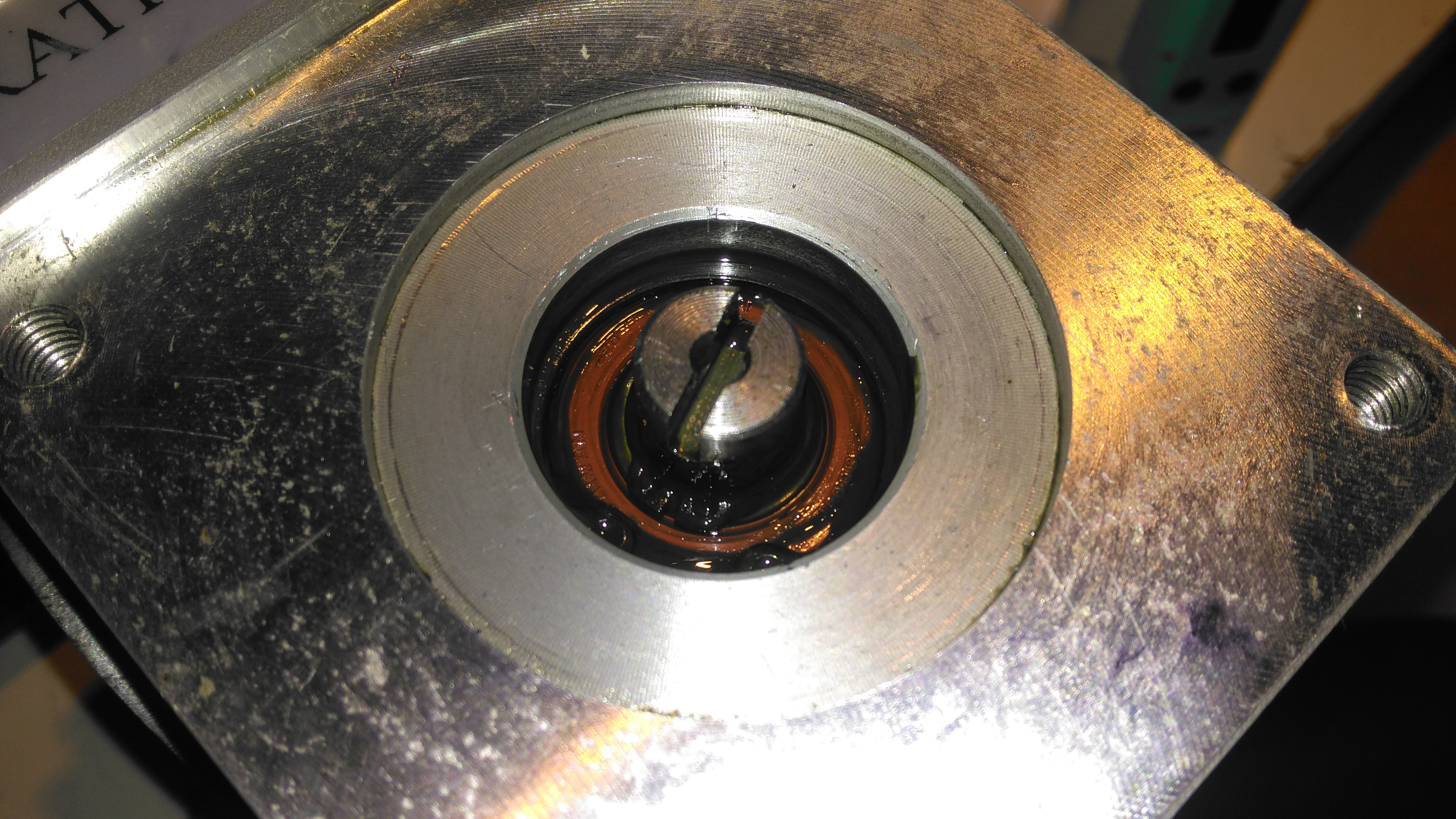
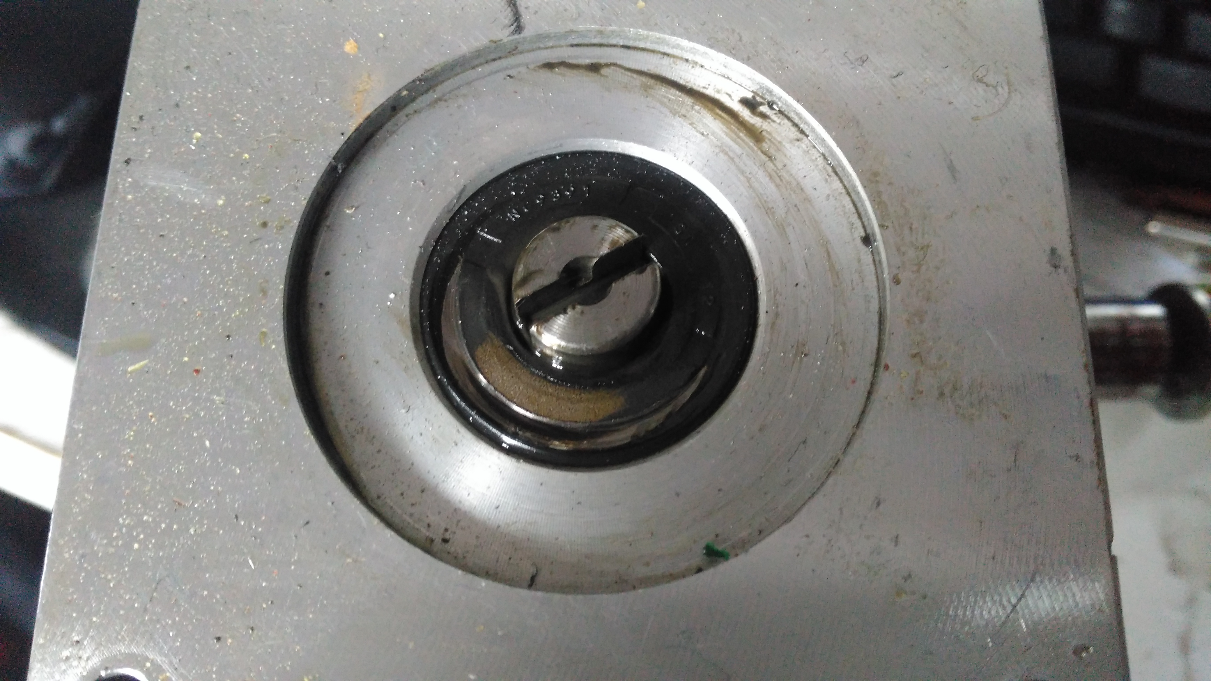
Input Shaft Seal
Here’s the failed seal on the left hand gearbox, the face damage was done by petrol immersion to clean everything up. (The seal is already compromised, so I’m not fussed about solvents eating the remaining rubber). The motor shaft is joined to the gearbox input by a rubber coupling.
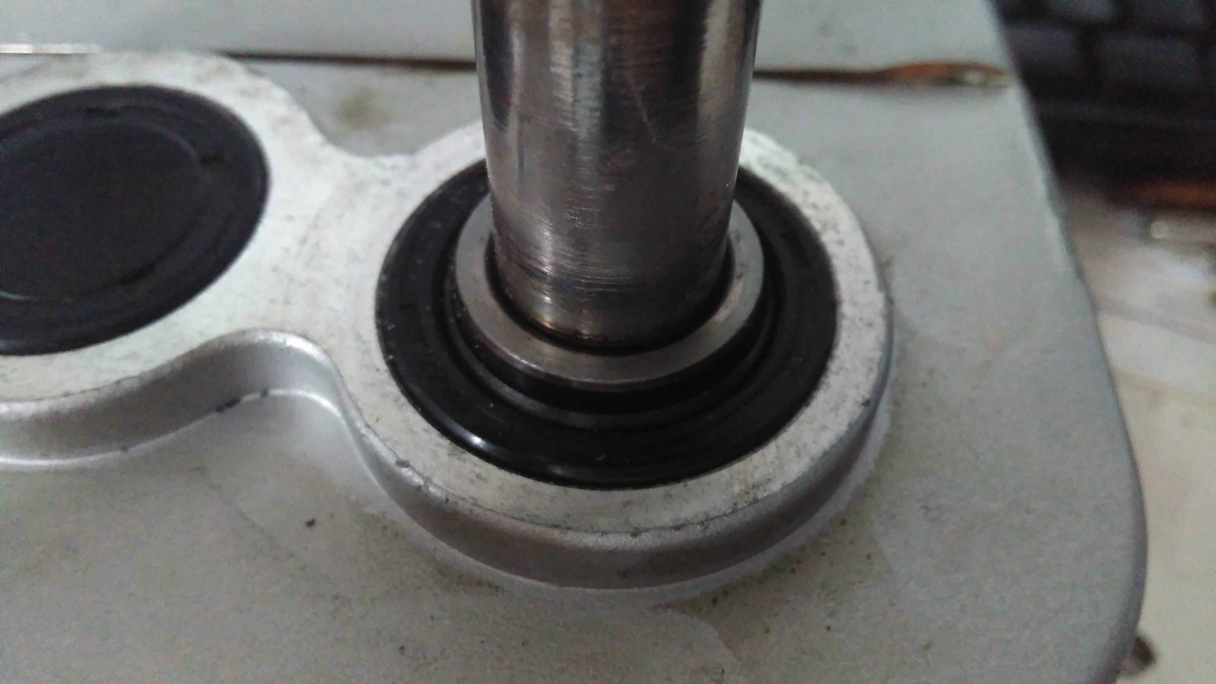
Output Shaft Seal
The output shaft seals seem to be still OK, there has been some seepage past the collar that the shaft rides in, but nothing more. This can be resealed with some Loctite bearing sealant. The sleeve is held into the gearbox by the wheel hub when in operation, but this doesn’t seal the gap unfortunately. I don’t know why the manufacturer didn’t just machine the shaft to that larger diameter, instead of using an extra sleeve to accommodate the seal.
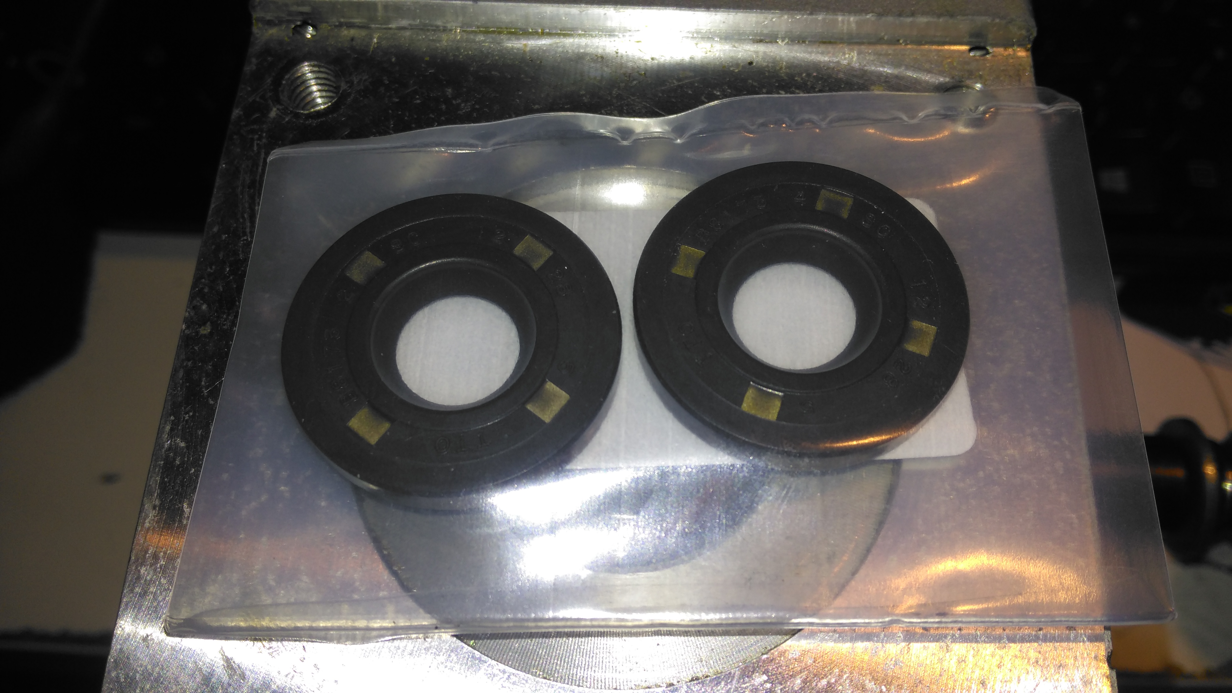
Bore Seals
The bore seals covering the ends of the shafts are also fine, which is a good thing, since I can’t seem to find replacements for these anywhere. The input shaft seals will be replaced on both gearboxes though.
Motor Contamination
The oil seal must have been leaking for a long while! This is the gearbox end of the wheelchair motor frame, completely clogged with grease. Luckily only a small amount has made it down past the armature to the brushgear.
Damaged Commutator
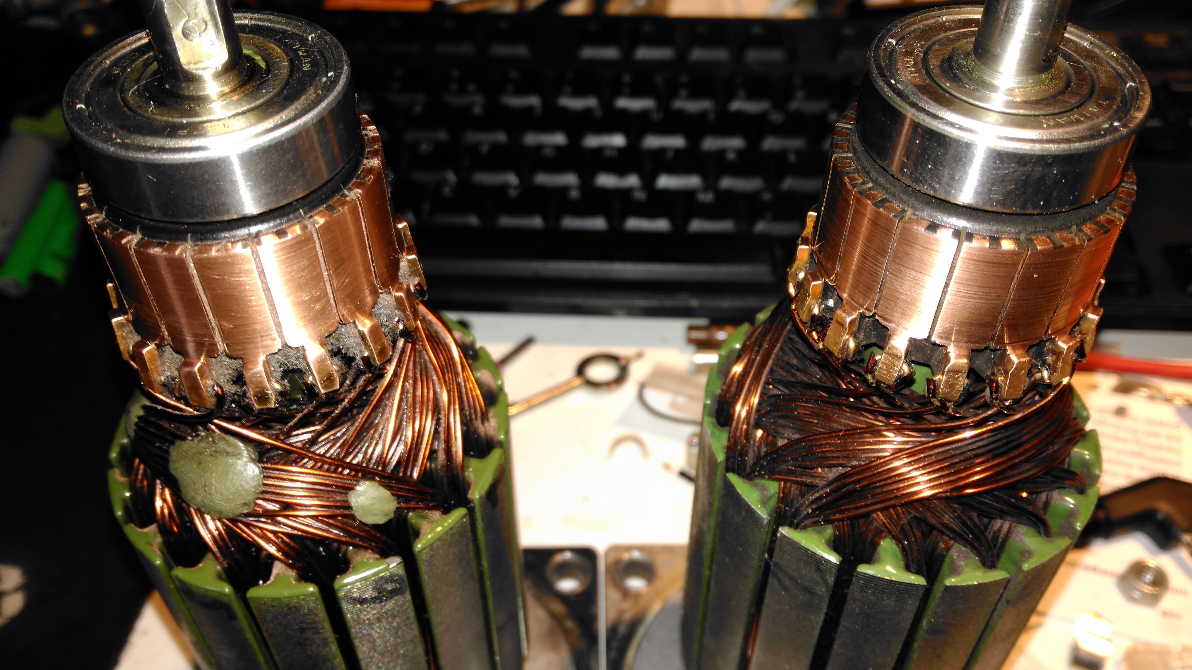
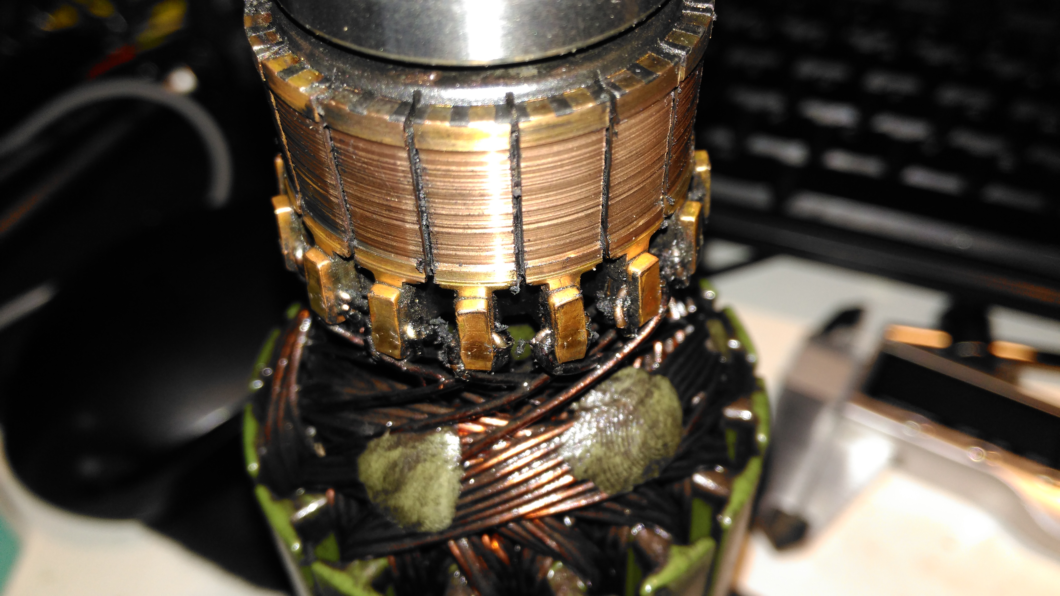
The commutator of this motor is badly damaged, and the brushes are very worn. This has been caused by the gearbox oil seal failing, and contaminating the motor internals with lubricant. The undercut between the segments is all but gone – filled with an abrasive mixture of brush dust, copper dust & old lubricant. Some repair work will be required here.
Second Motor
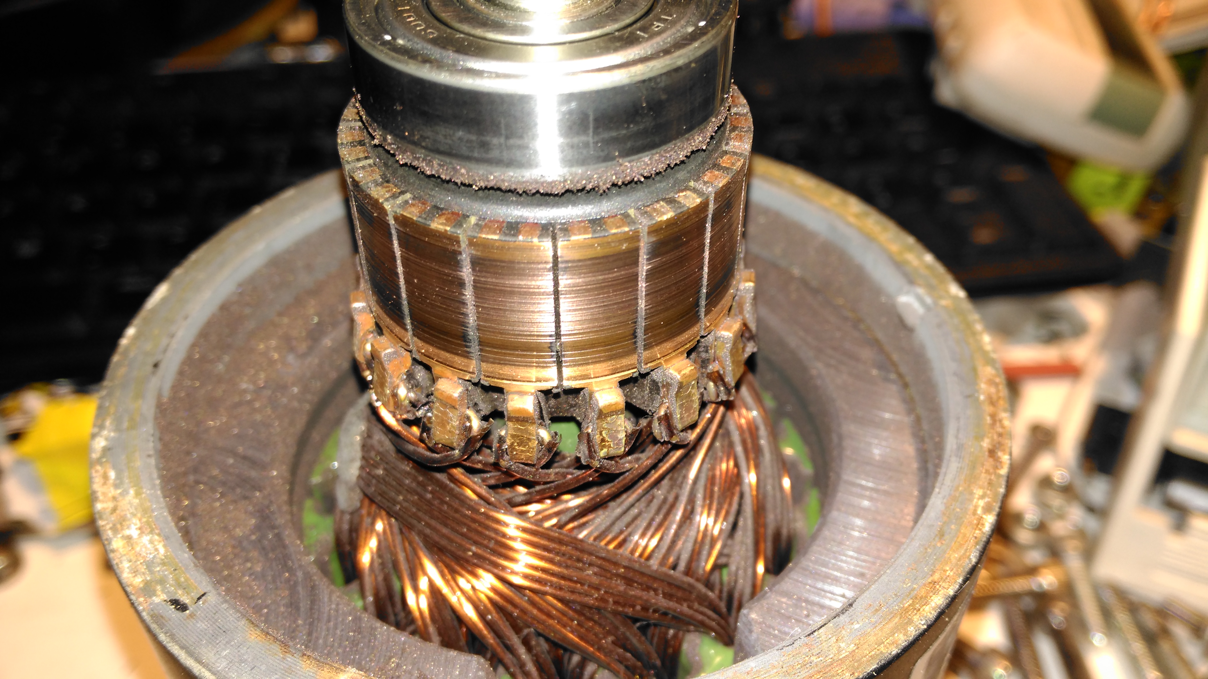
Here’s the brushgear removed from the second wheelchair motor, this one looks much more normal, and there’s not as much wear on the brushes or the commutator. Just the usual coating of brush dust.
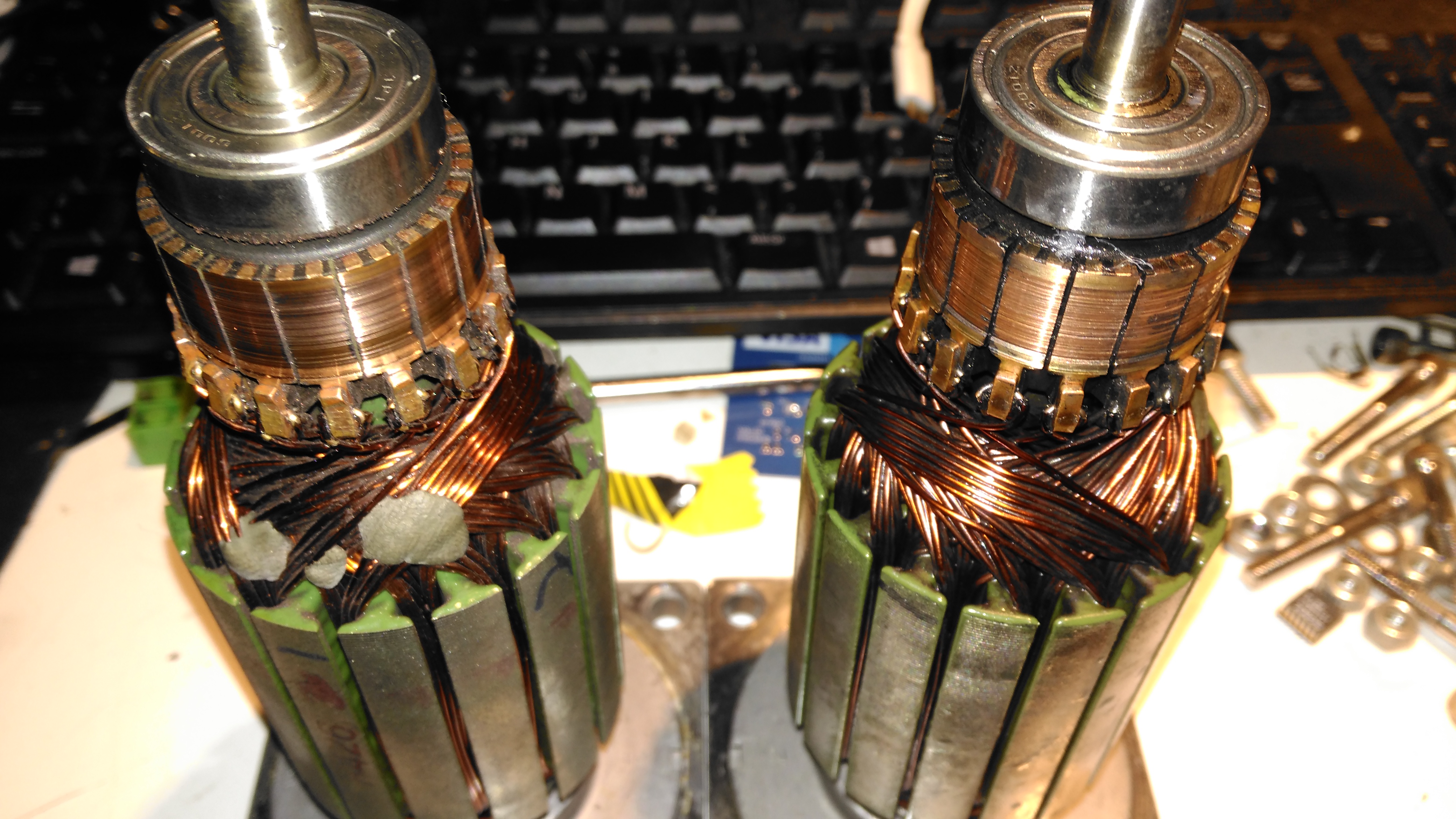
Armatures
Here’s both armatures together, with the contaminated one on the right, after some cleaning to remove most of the greasy old grok & brush dust from everything. The windings on the damaged left hand wheelchair motor haven’t darkened, which I would expect from severe overheating damage, so I’m hoping this armature is OK, and won’t require a rewind. Using an ohmmeter on these windings doesn’t tell me much – there’s only 7 turns of 0.86mm (20AWG) magnet wire in each coil, so they read as a dead short anyway. There was some leakage between the windings and the core before I cleaned things up – this was in the high (28+) megohms range, but this seems to have cleared now I’ve given things a real good cleaning.
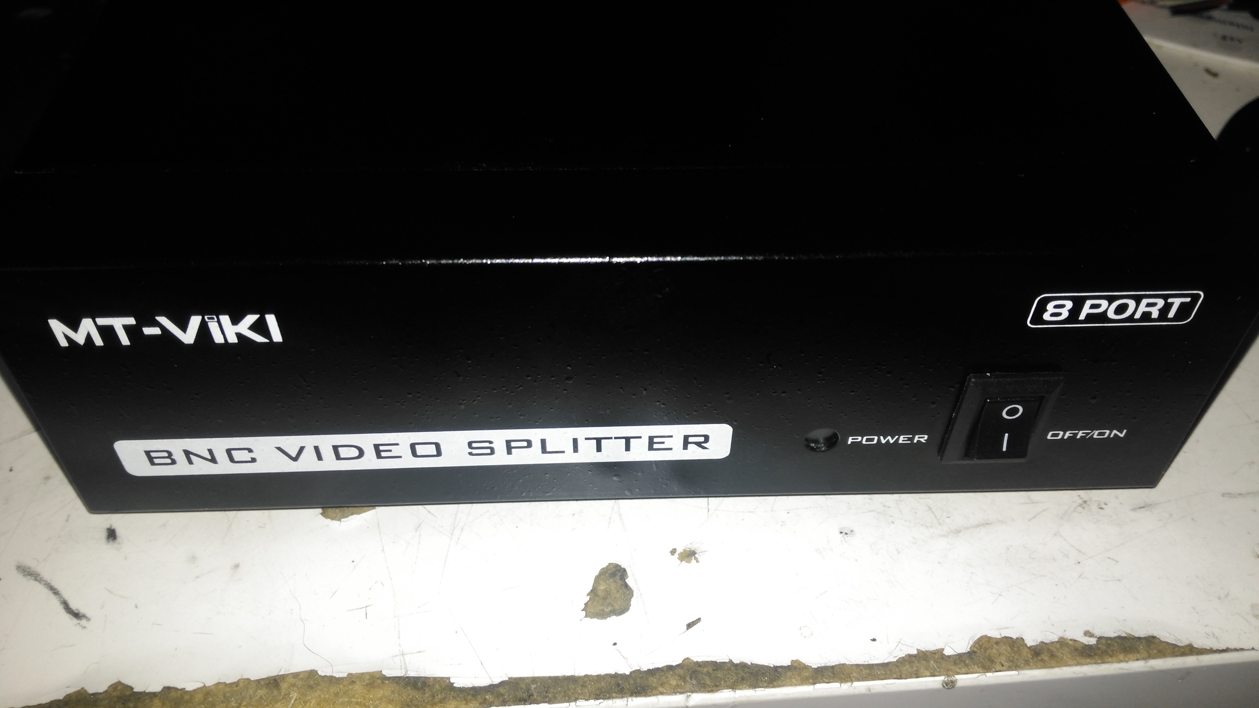
Time for another eBay special: this time it’s an 8-port video distribution amplifier, with BNC connections designed for commercial/industrial equipment. Not much on the front panel above, apart from the power switch & LED.
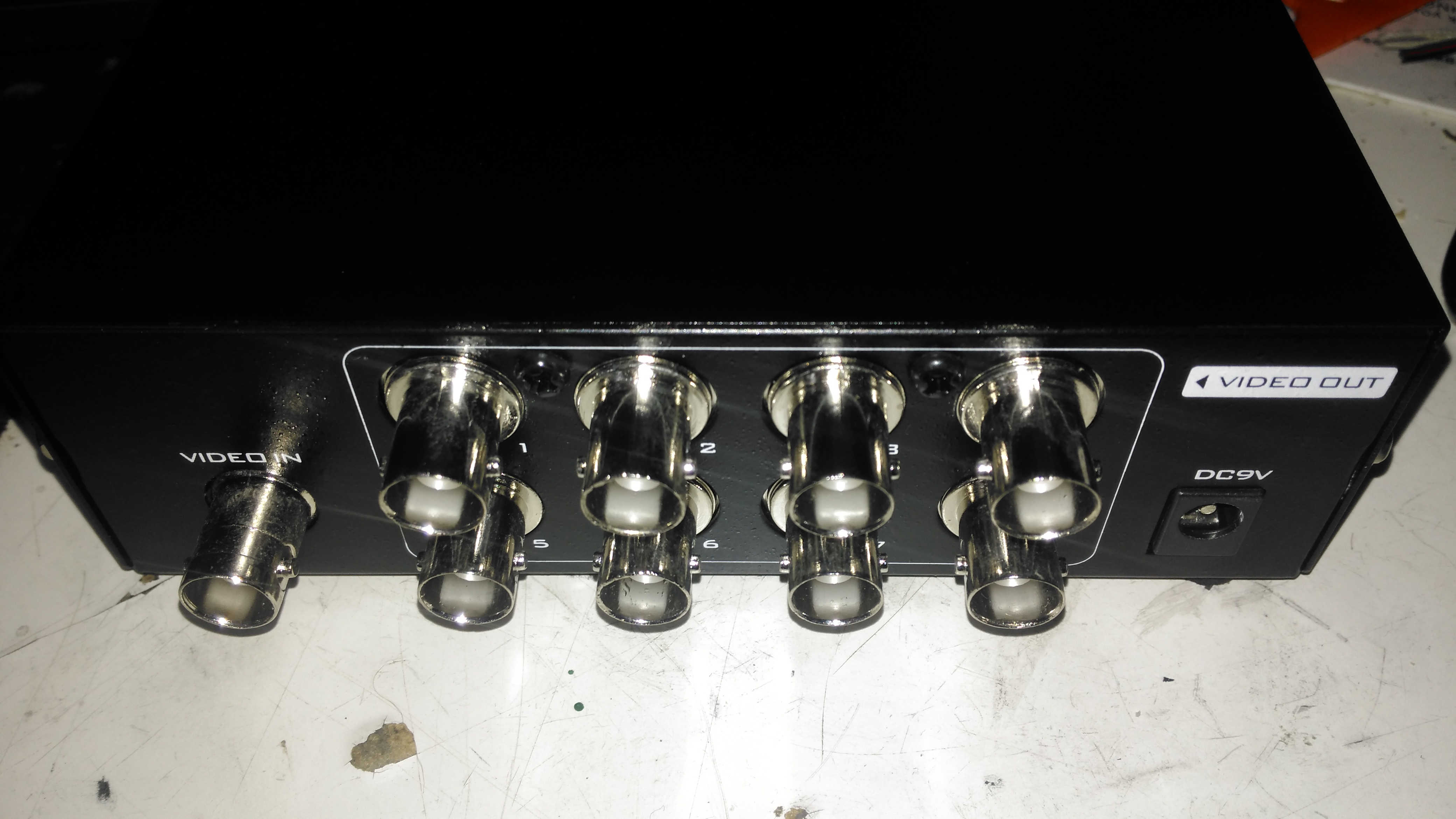
Rear Panel
The rear panel has all the connectors, input is on the left, while the outputs are in the centre. Power is supplied through the barrel jack on the right, 9v DC in this case.
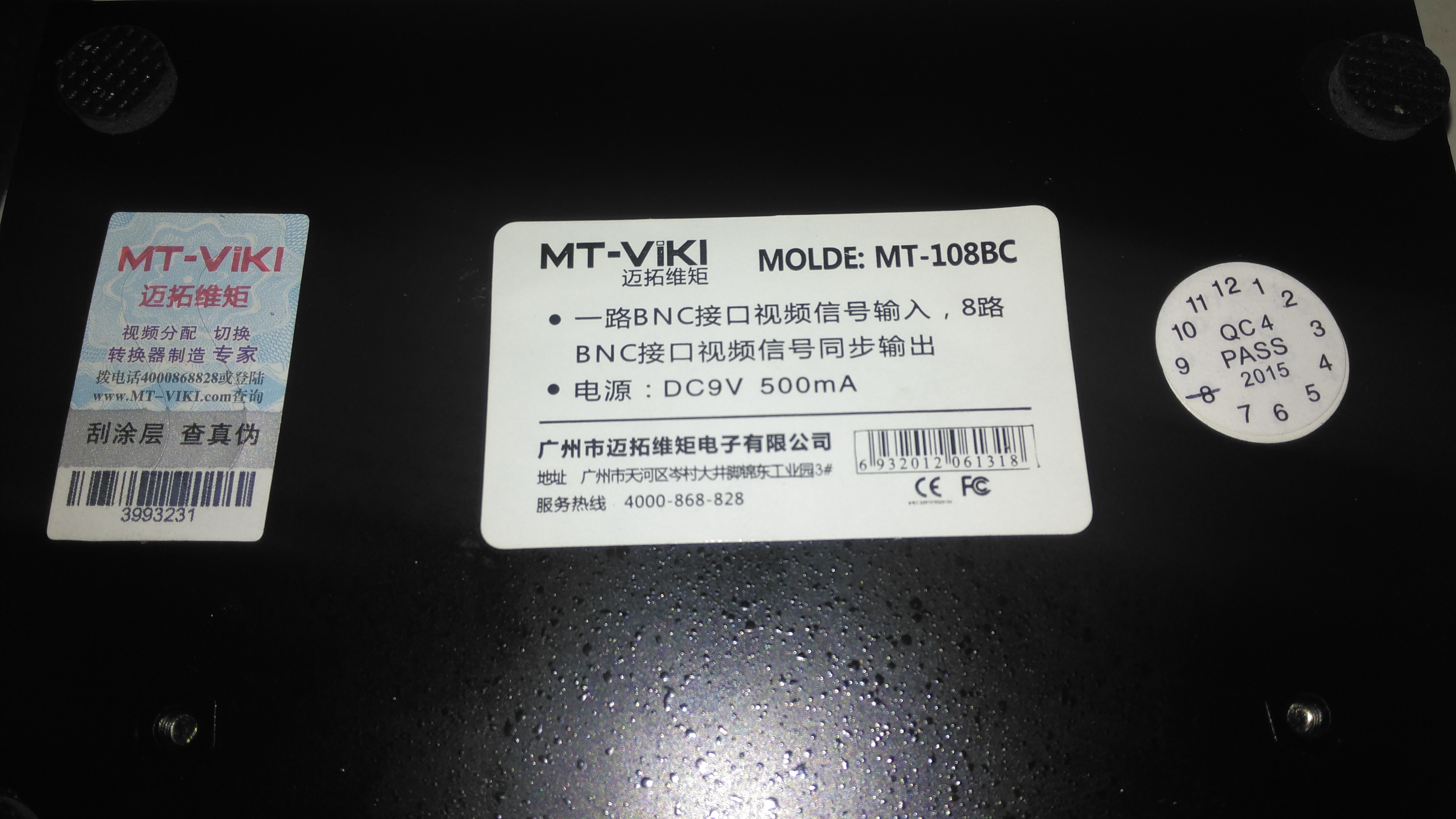
Data Label
Not much in English on the data labels, there’s also an authenticity label on the left to make sure you don’t get a fake.
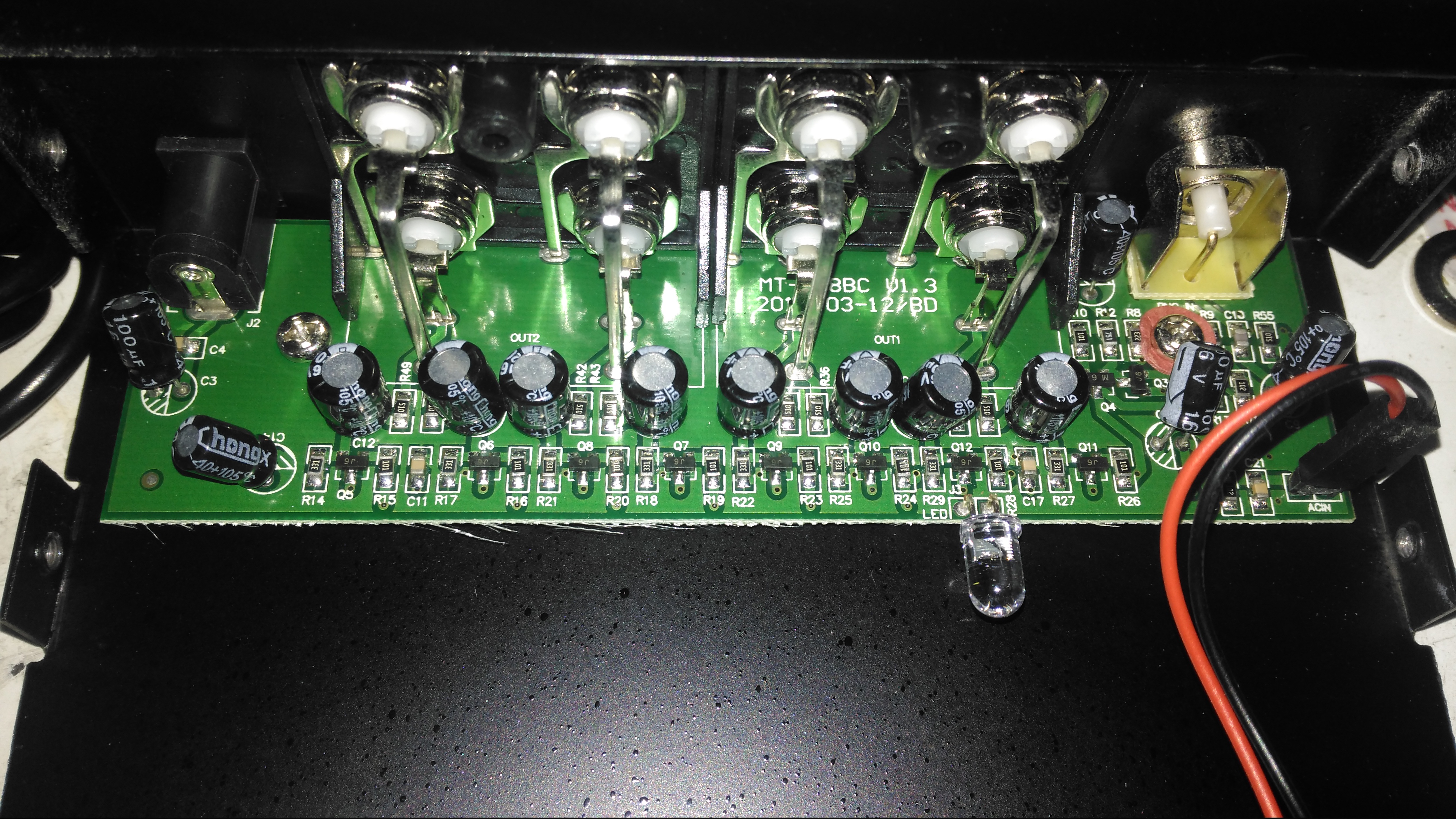
Amplifier Board
Taking the lid off reveals a very small PCB, taking up less than a third of the aluminium case! The input stage is on the right, composed of a pair of SOT-23 transistors to buffer the incoming signal. There’s an KST812M6 PNP & an S9014 NPN Epitaxial. The signal is then fed to the output stages, all individual S9014 NPN transistors to the output ports.
The power LED is just poking in the general direction of the hole in the front panel, so this isn’t likely to work very well – it’s going to illuminate the inside of the case more!
As many will already know, we lost a guiding light in the Rock World last week, Chester Bennington of Linkin Park. I am reposting the message from the other bandmembers here, being one of the first bands I ever listened to of this genre. As someone with mental illness, seeing someone identify their depression, and having it still kill them is rather disturbing.
RIP Chester, Forever With Us In Song
Dear Chester,
Our hearts are broken. The shockwaves of grief and denial are still sweeping through our family as we come to grips with what has happened.
You touched so many lives, maybe even more than you realized. In the past few days, we’ve seen an outpouring of love and support, both public and private, from around the world. Talinda and the family appreciate it, and want the world to know that you were the best husband, son, and father; the family will never be whole without you.
Talking with you about the years ahead together, your excitement was infectious. Your absence leaves a void that can never be filled—a boisterous, funny, ambitious, creative, kind, generous voice in the room is missing. We’re trying to remind ourselves that the demons who took you away from us were always part of the deal. After all, it was the way you sang about those demons that made everyone fall in love with you in the first place. You fearlessly put them on display, and in doing so, brought us together and taught us to be more human. You had the biggest heart, and managed to wear it on your sleeve.
Our love for making and performing music is inextinguishable. While we don’t know what path our future may take, we know that each of our lives was made better by you. Thank you for that gift. We love you, and miss you so much.
For years now I’ve used Virtualmin for my hosting requirements, and have made use of Procmail to filter my mail into folders (it’s the default, and rather tightly integrated). The only issue with this system is having to login to two different things for mail: I use Rainloop Webmail for general mail viewing, but the Procmail filters are only editable through the Usermin section of Virtualmin. This is awkward to say the least, so being able to use Sieve which is already supported by Rainloop is a better option. (Sieve is also supported via plugin in Roundcube).
Since we’re going to still need Procmail for the Virtualmin-managed Spam & Virus scanning functions, we will add Sieve at the end of Procmail. There are some
First thing, get Sieve installed via Dovecot, with the following:
yum install dovecot-pigeonhole
Some configuration changes are required to Dovecot to get the Sieve server running, /etc/dovecot/conf.d/15-lda.conf should have this section:
protocol lda {
 # Space separated list of plugins to load (default is global mail_plugins).
 mail_plugins = sieve
}
Finally, in /etc/dovecot/conf.d/20-managesieve.conf, uncomment this section to enable the managesieve server:
service managesieve-login {
 inet_listener sieve {
 port = 4190
 }
}
After these changes are made, restart Dovecot to get the configs reloaded. It’s easy to check if the Sieve server is listening by running the following command:
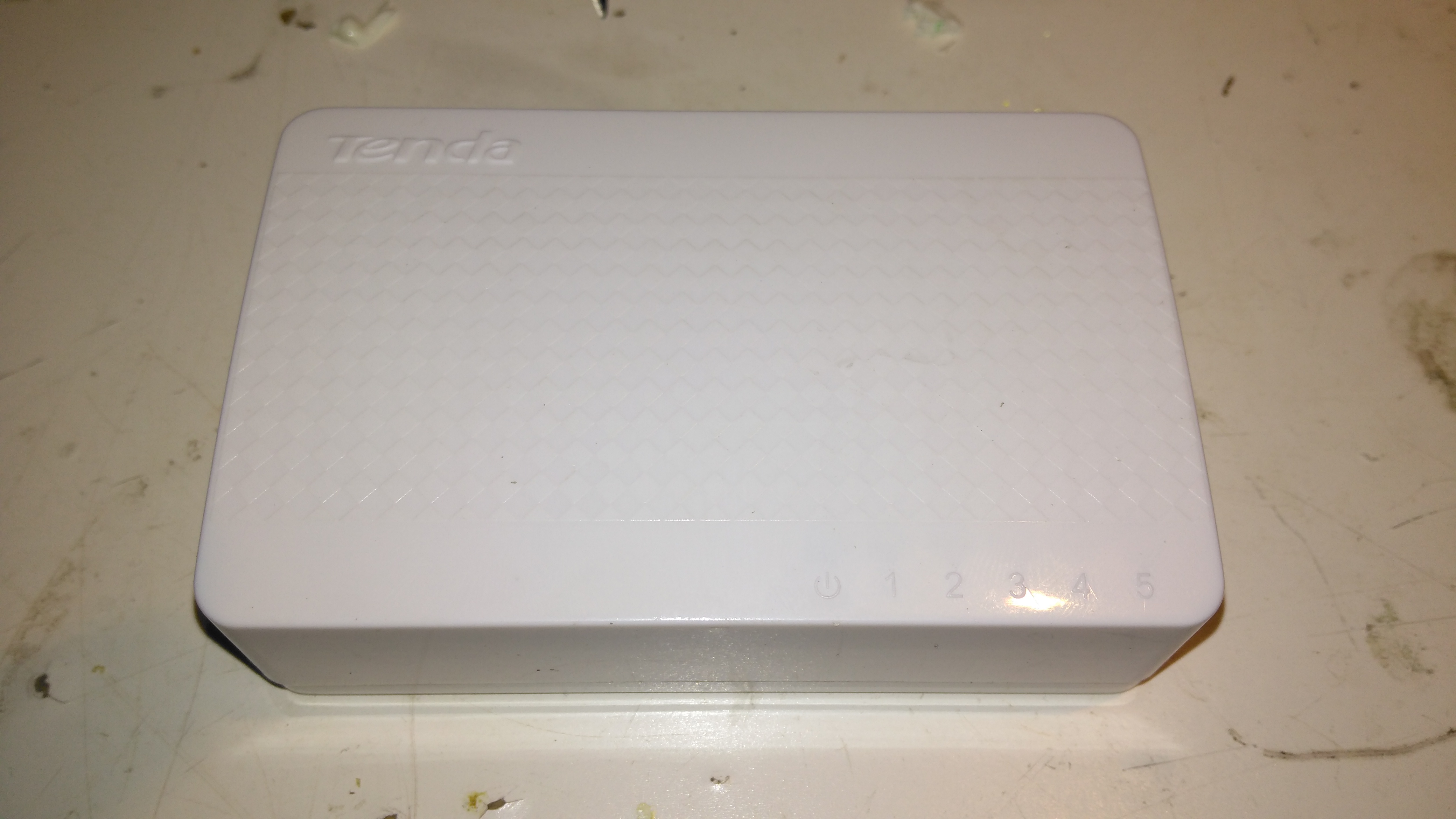
Here’s a tiny ethernet switch from the great fle market that is eBay – the Tenda S105. This unit has 5 ports, but only supports 10/100M. Still, for something so small it’s not bad.
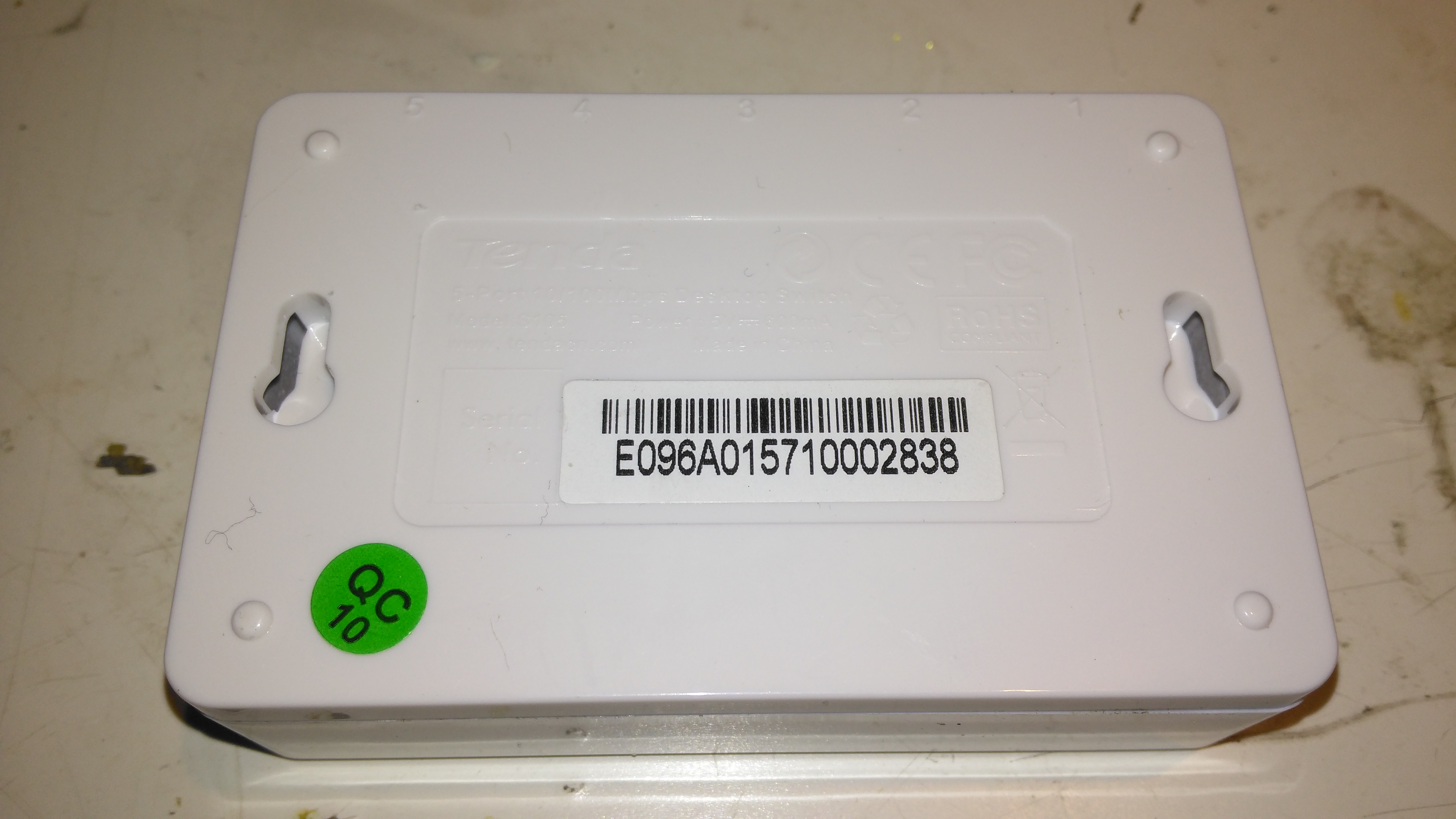
Bottom
Not much on the bottom, there’s a pair of screw hooks for mounting this to a surface.
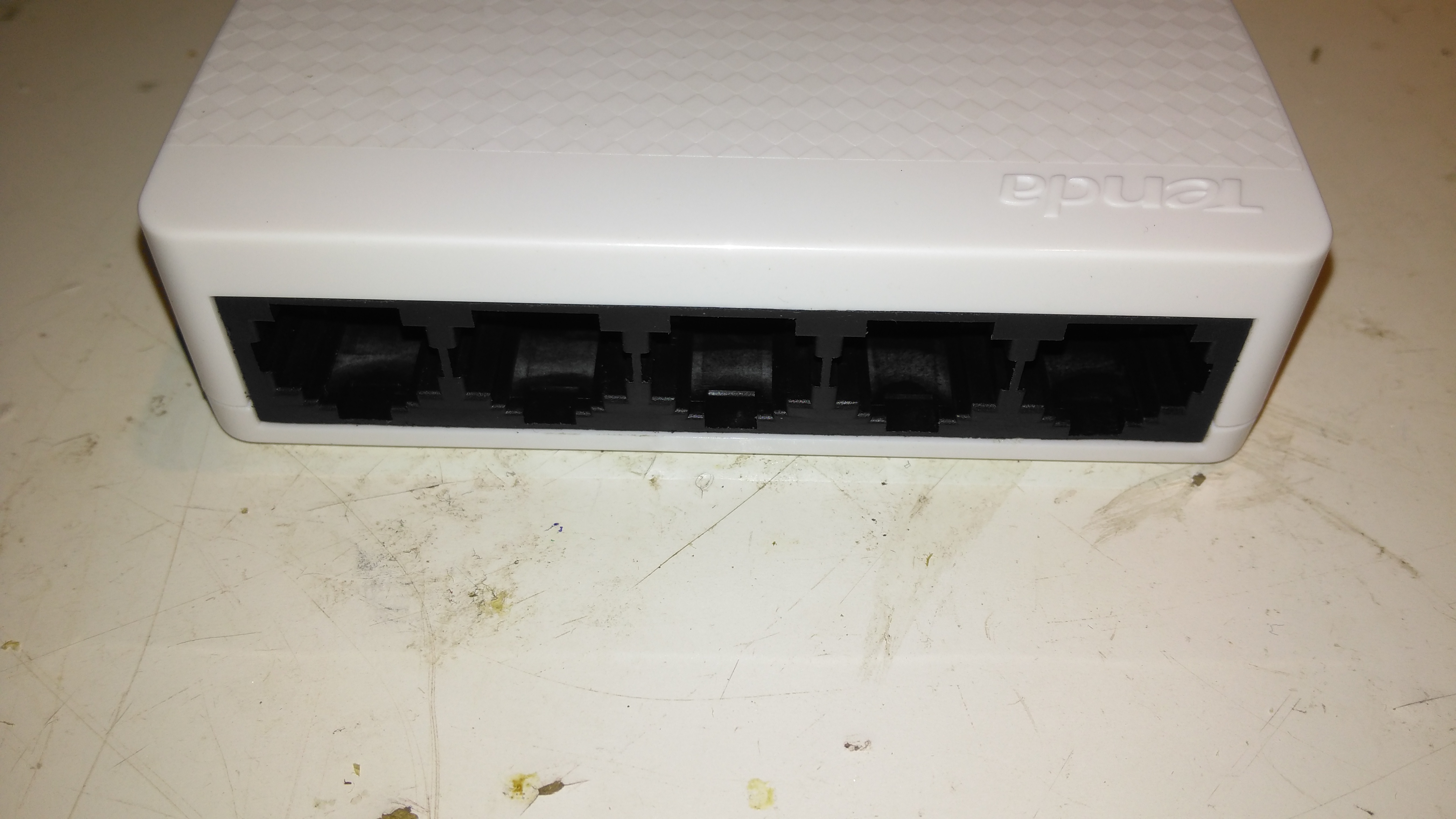
Ports
The 5 ports on the front actually have the pins for the unused pairs of the ethernet cables removed – saving every penny here.
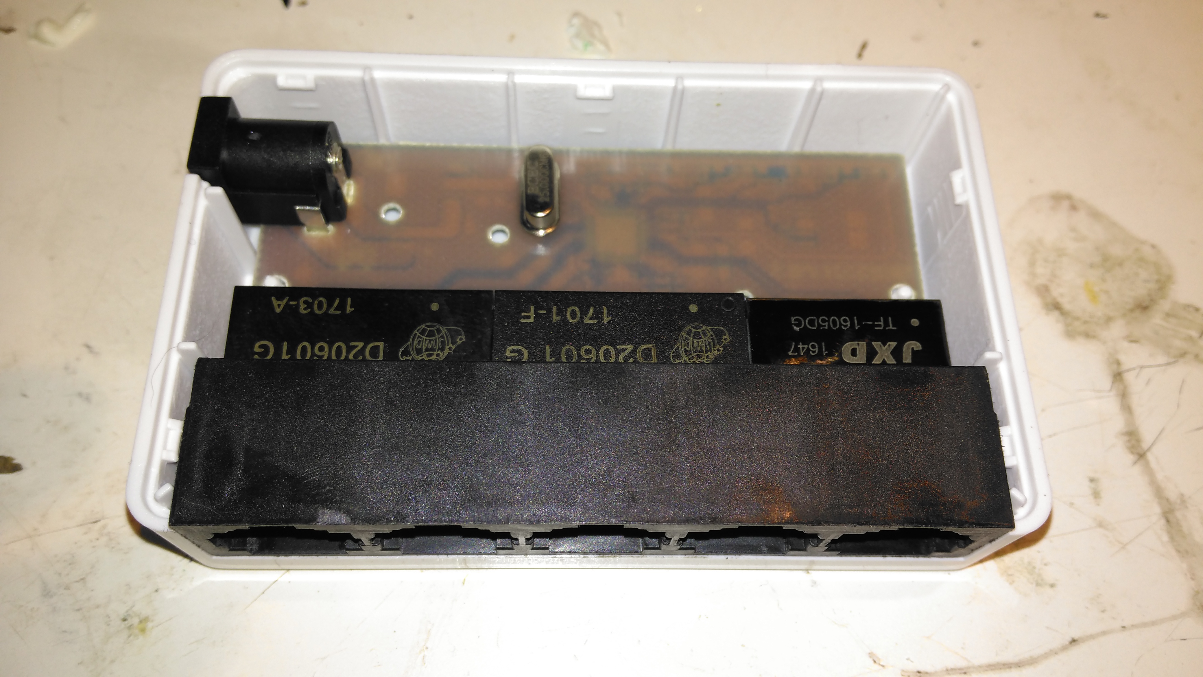
PCB Top
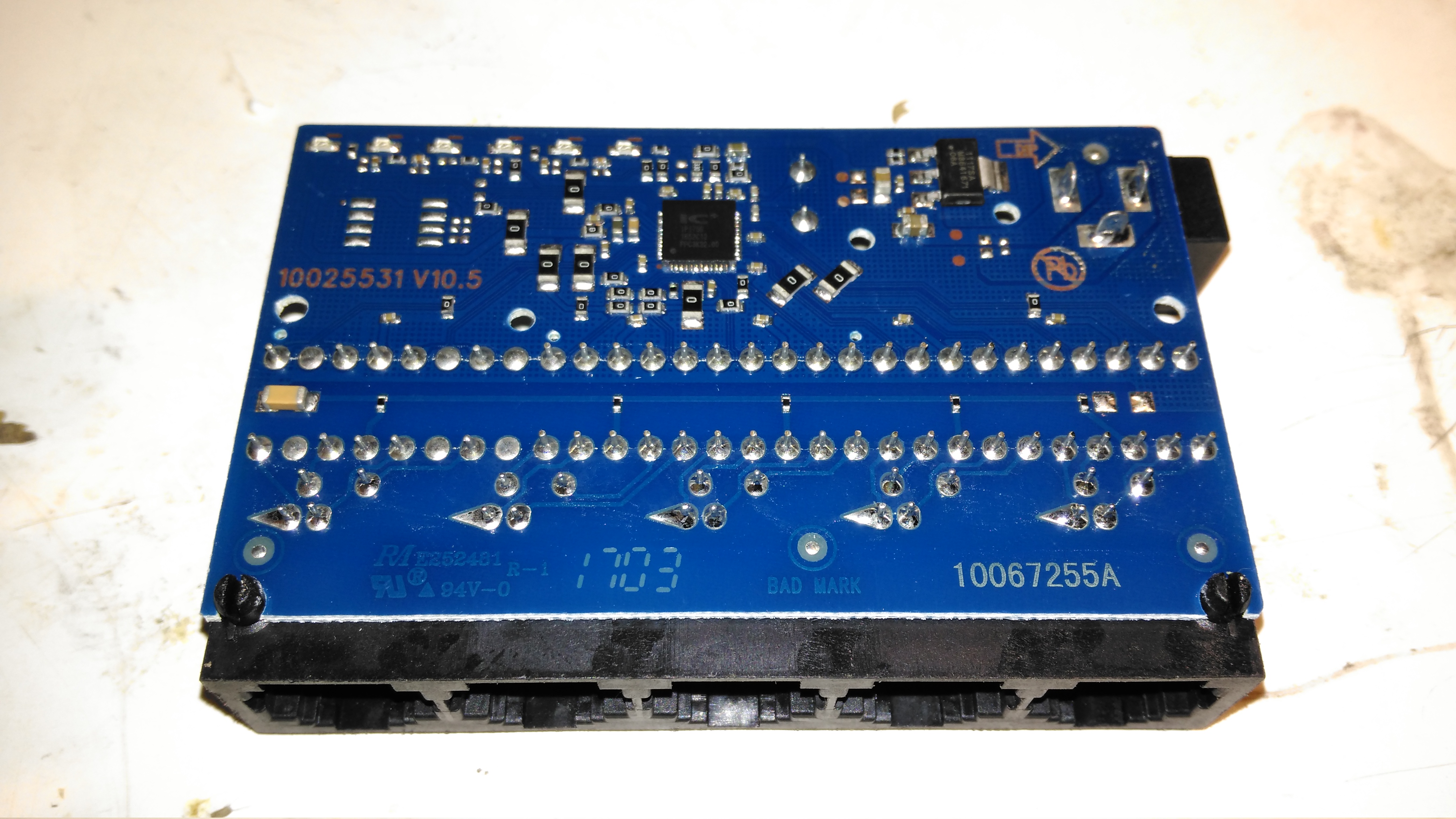
The casing just unclips, revealing the small PCB. Nothing much on the top, just the connectors, isolating transformers & the crystal for the switch IC.
PCB Bottom
The bottom of the PCB is a little more busy, mainly with decoupling components. There’s a 3.3v linear regulator to step down the 5v input for the switch IC.
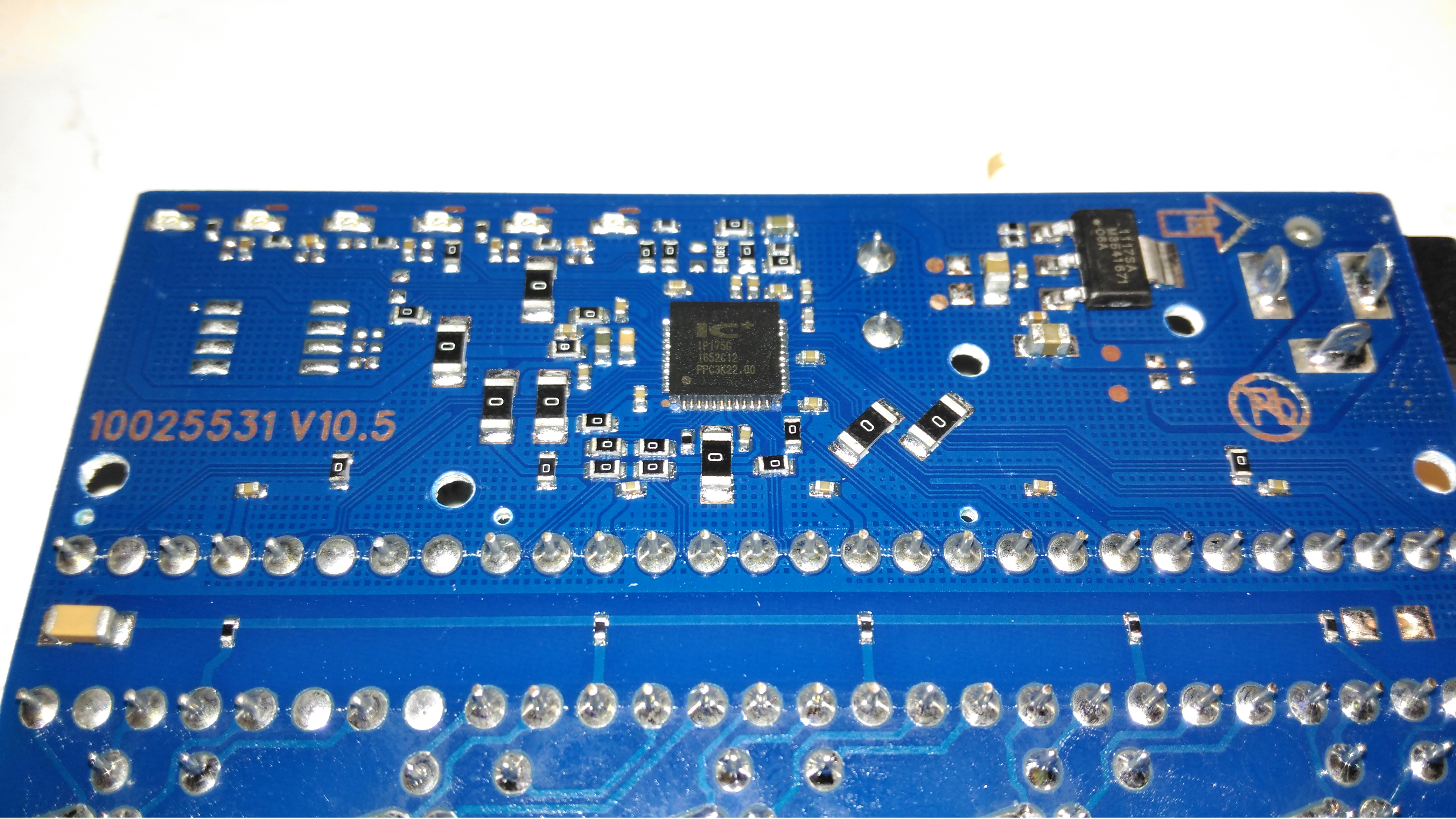
Switch IC
The IC doing all the data switching is an IP175G 5-Port 10/100 Switch from IC+ Corp. No datasheet available for this, but it’s going to be a bog-standard switch.
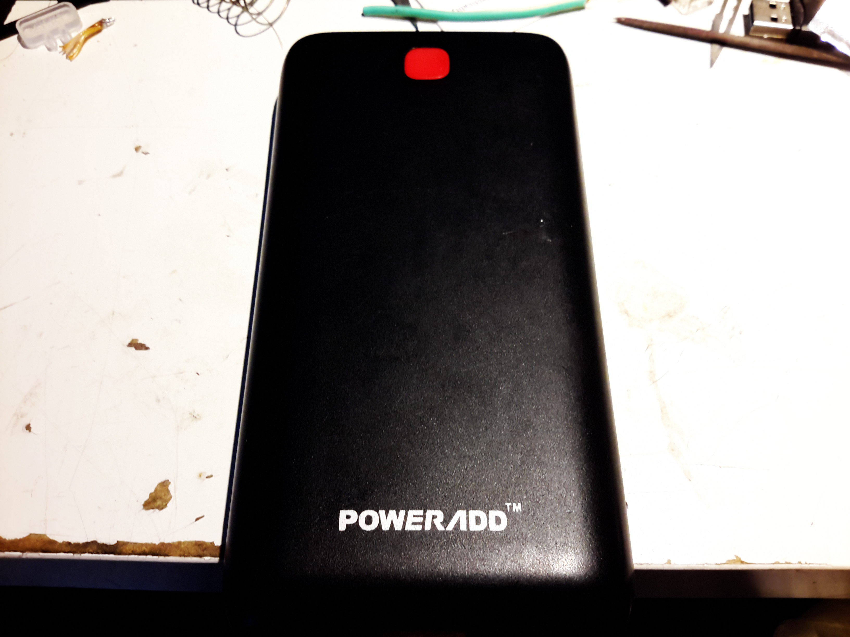
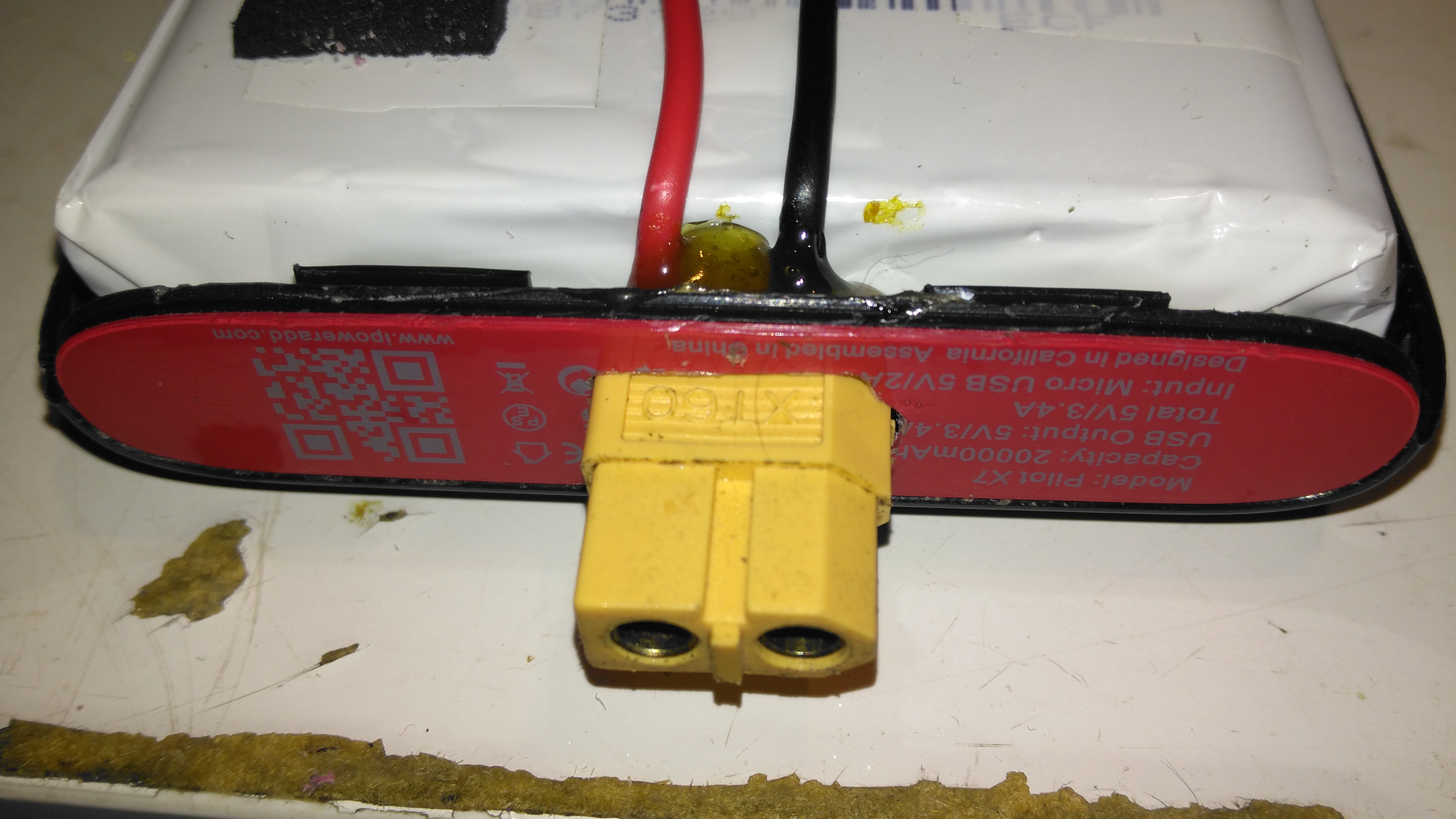
Here’s the biggest portable USB powerbank I’ve seen yet – the PowerAdd Pilot X7, this comes with a 20Ah (20,000mAh) capacity. This pack is pretty heavy, but this isn’t surprising considering the capacity.
USB Ports & LED
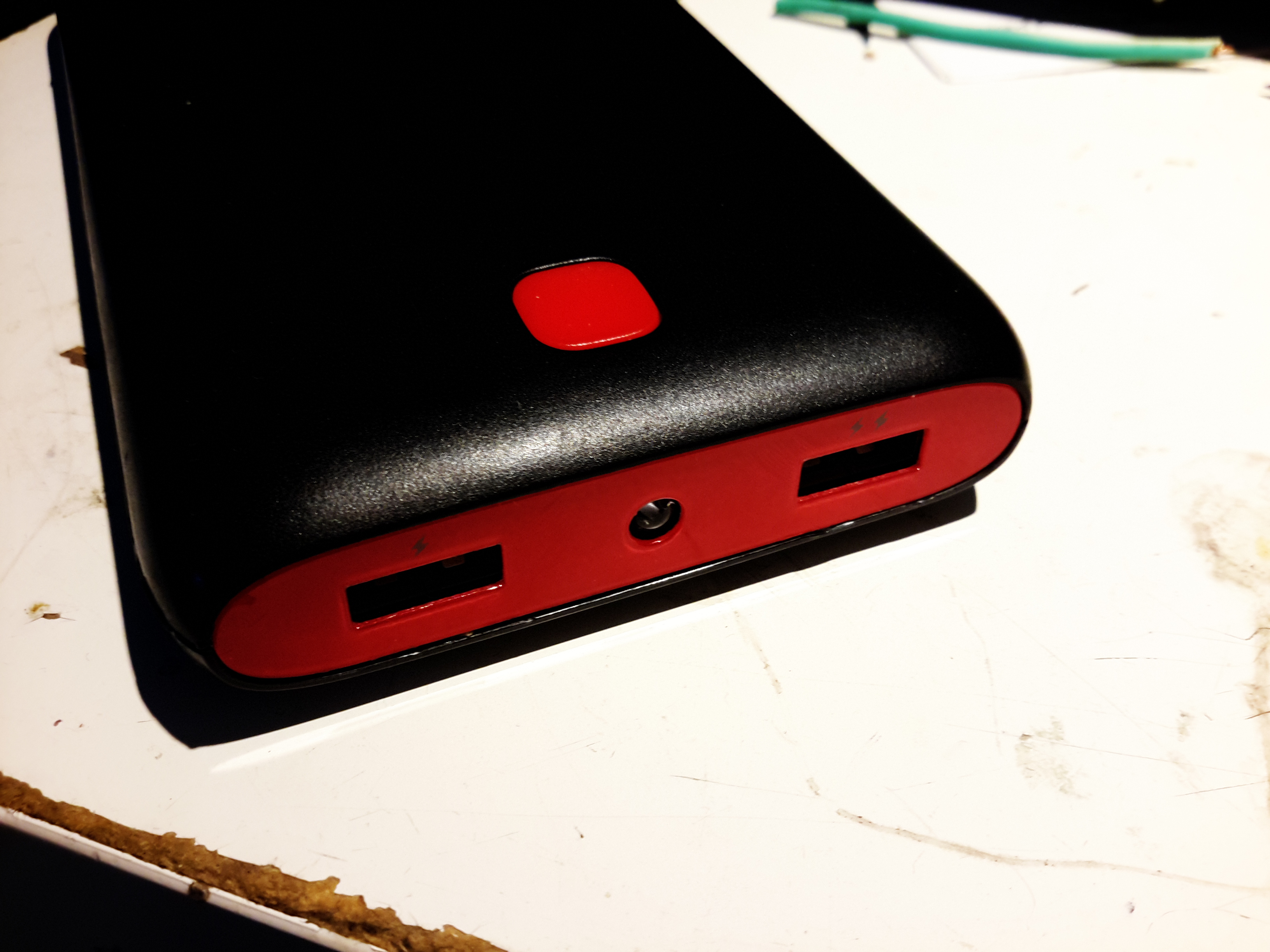
The front of the pack houses the usual USB ports, in this case rated at 3.4A total between the ports. There’s a white LED in the centre as a small torch, activated by double-clicking the button. A single click of the button lights up the 4 blue LEDs under the housing that indicate remaining battery capacity. Factory charging is via a standard µUSB connector in the side, at a maximum of 2A.
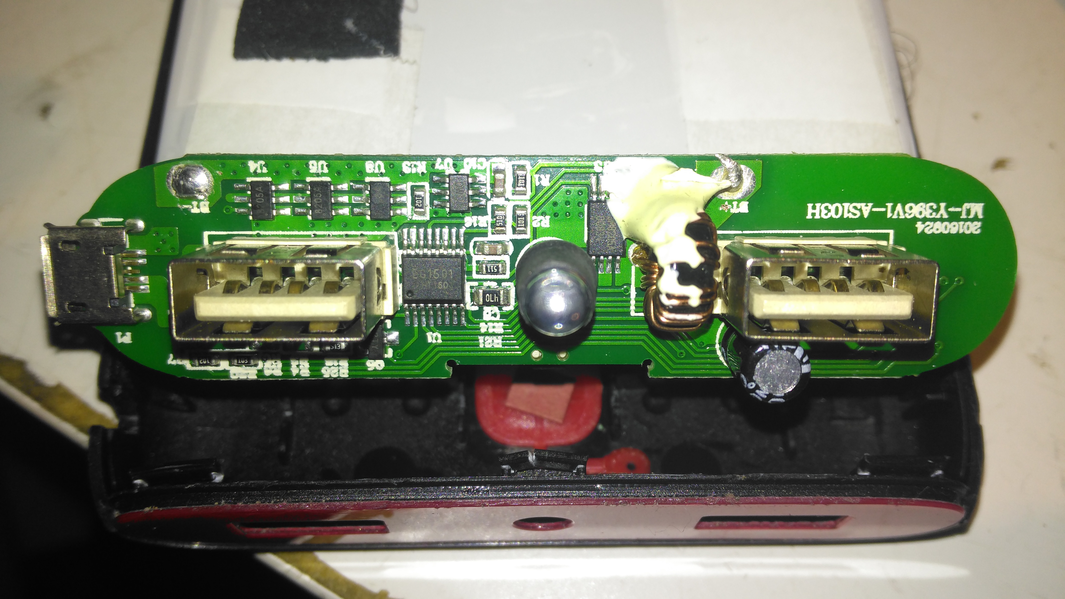
PCB Front
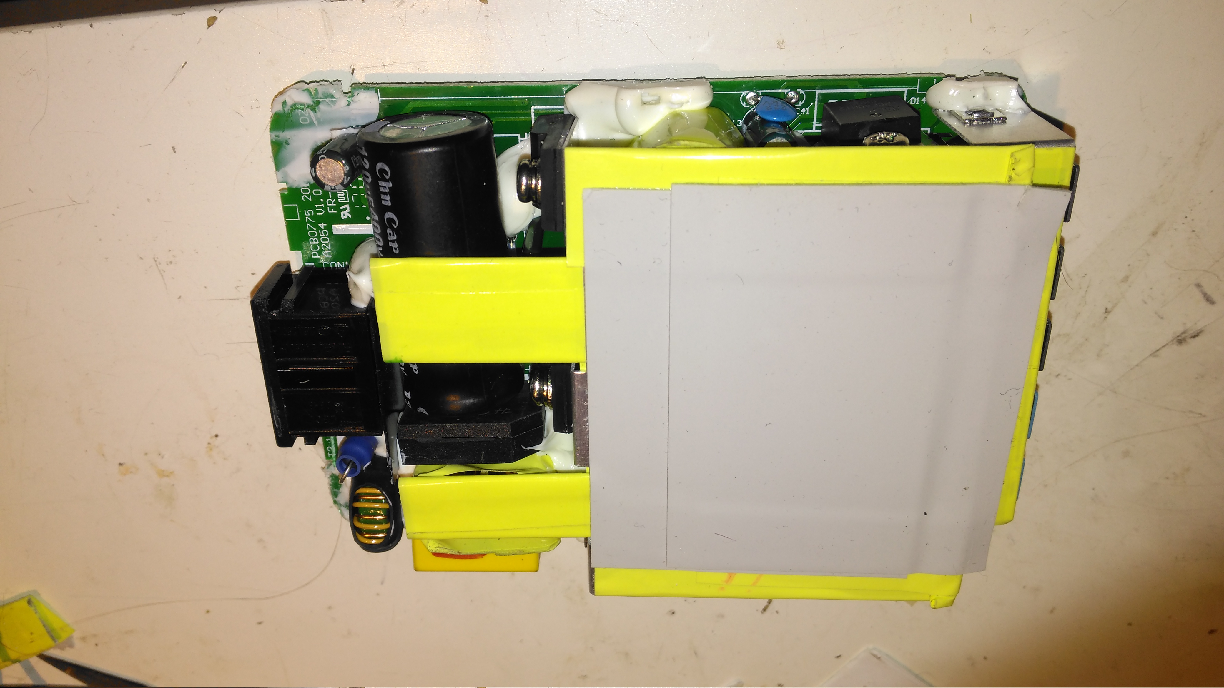
The front of the PCB holds the USB ports, along with most of the main control circuitry. At top left is a string of FS8025A dual-MOSFETs all in parallel for a current carrying capacity of 15A total, to the right of these is the ubiquitous DW01 Lithium-Ion protection IC. These 4 components make up the battery protection – stopping both an overcharge & overdischarge. The larger IC below is an EG1501 multi-purpose power controller.
This chip is doing all of the heavy lifting in this power pack, dealing with all the DC-DC conversion for the USB ports, charge control of the battery pack, controlling the battery level indicator LEDs & controlling the torch LED in the centre.
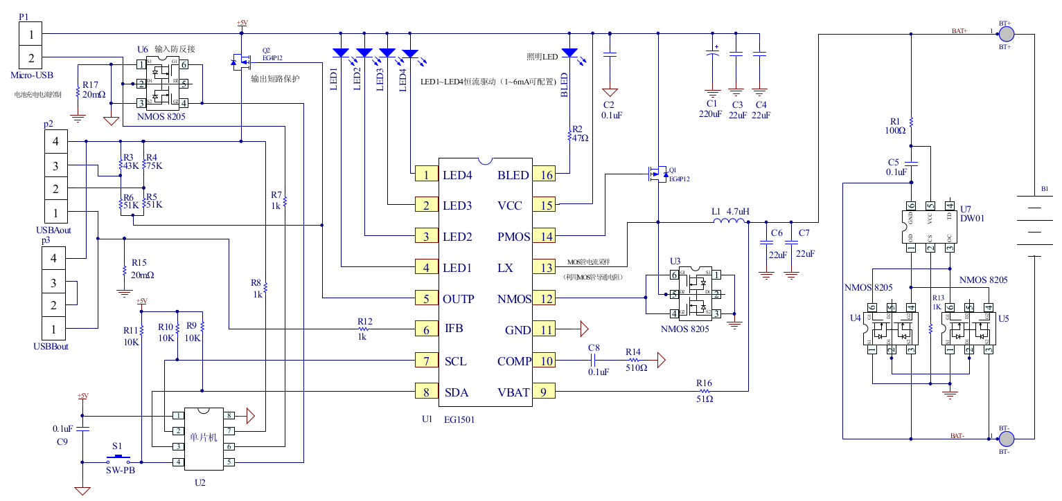
EG1501 Example
The datasheet is in Chinese, but it does have an example application circuit, which is very similar to the circuitry used in this powerbank. A toroidal inductor is nestled next to the right-hand USB port for the DC-DC converter, and the remaining IC next to it is a CW3004 Dual-Channel USB Charging Controller, which automatically sets the data pins on the USB ports to the correct levels to ensure high-current charging of the devices plugged in. This IC replaces the resistors R3-R6 in the schematic above.
The DC-DC converter section of the power chain is designed with high efficiency in mind, not using any diodes, but synchronous rectification instead.
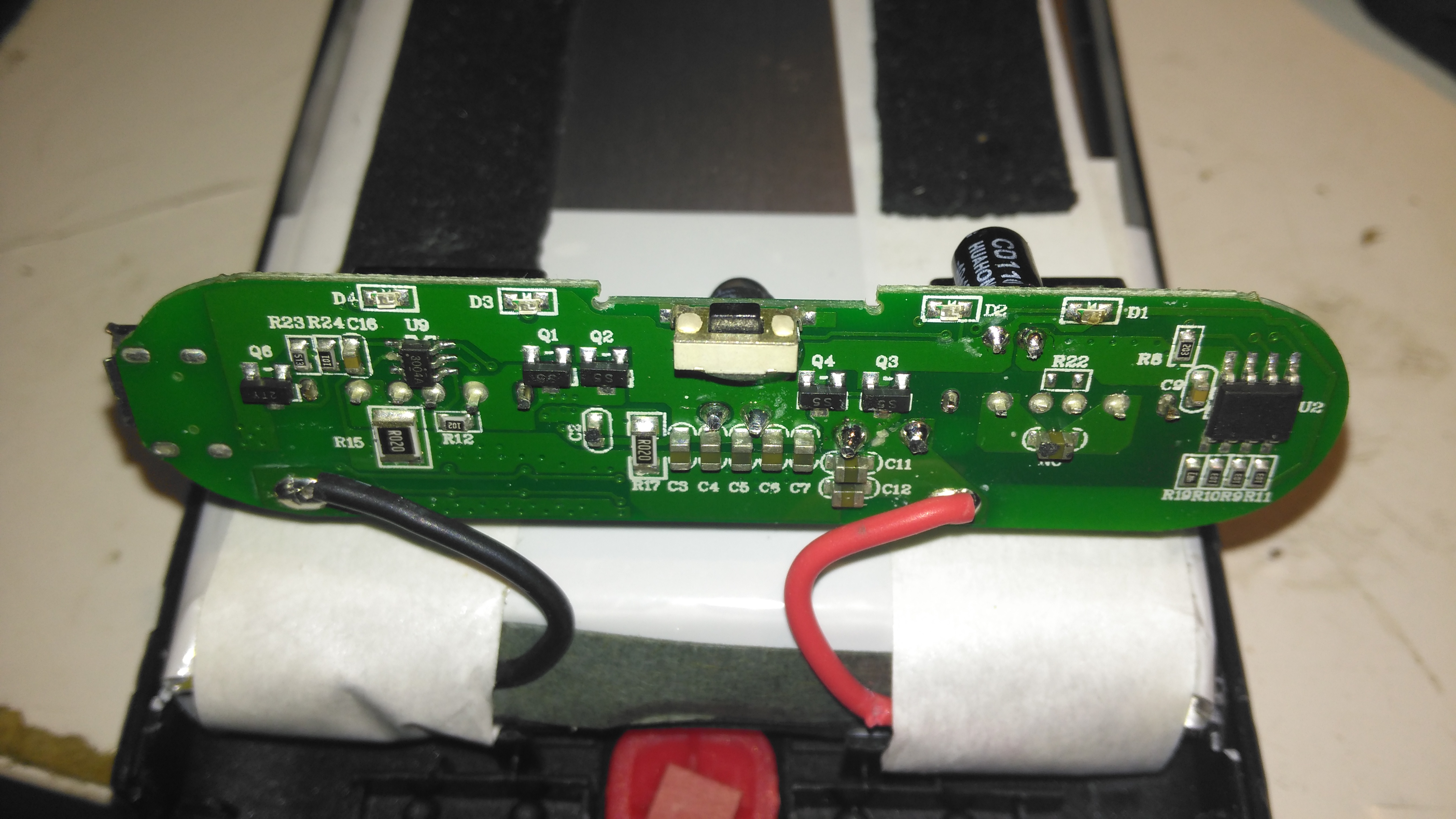
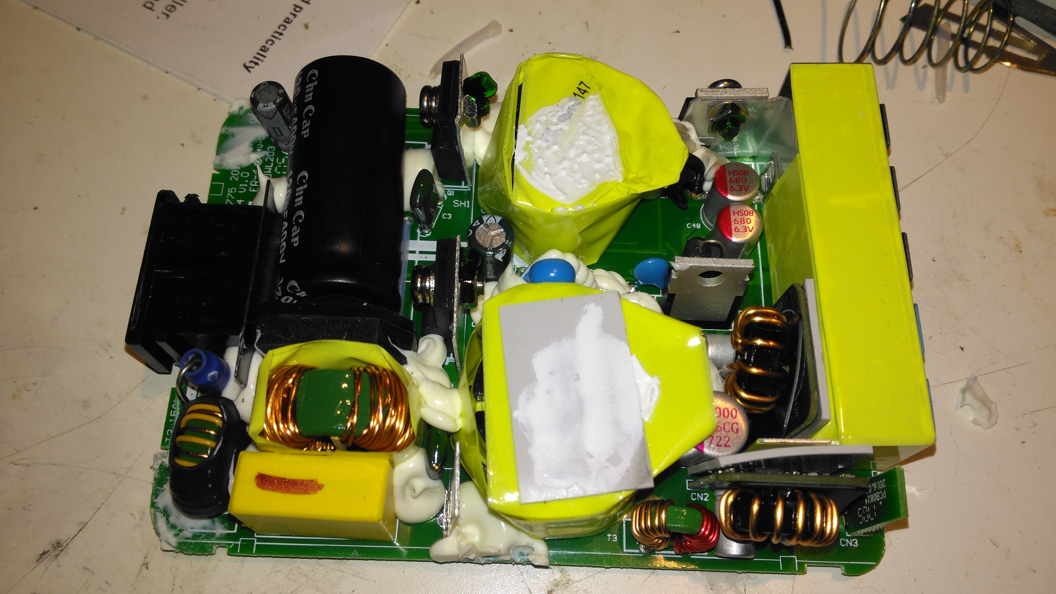
PCB Back
The back of the PCB just has a few discrete transistors, the user interface button, and a small SO8 IC with no markings at all. I’m going to assume this is a generic microcontroller, (U2 in the schematic) & is just there to interface the user button to the power controller via I²C.
Cells
Not many markings on the cells indicating their capacity, but a full discharge test at 4A gave me a resulting capacity of 21Ah – slightly above the nameplate rating. There are two cells in here in parallel, ~10Ah capacity each.
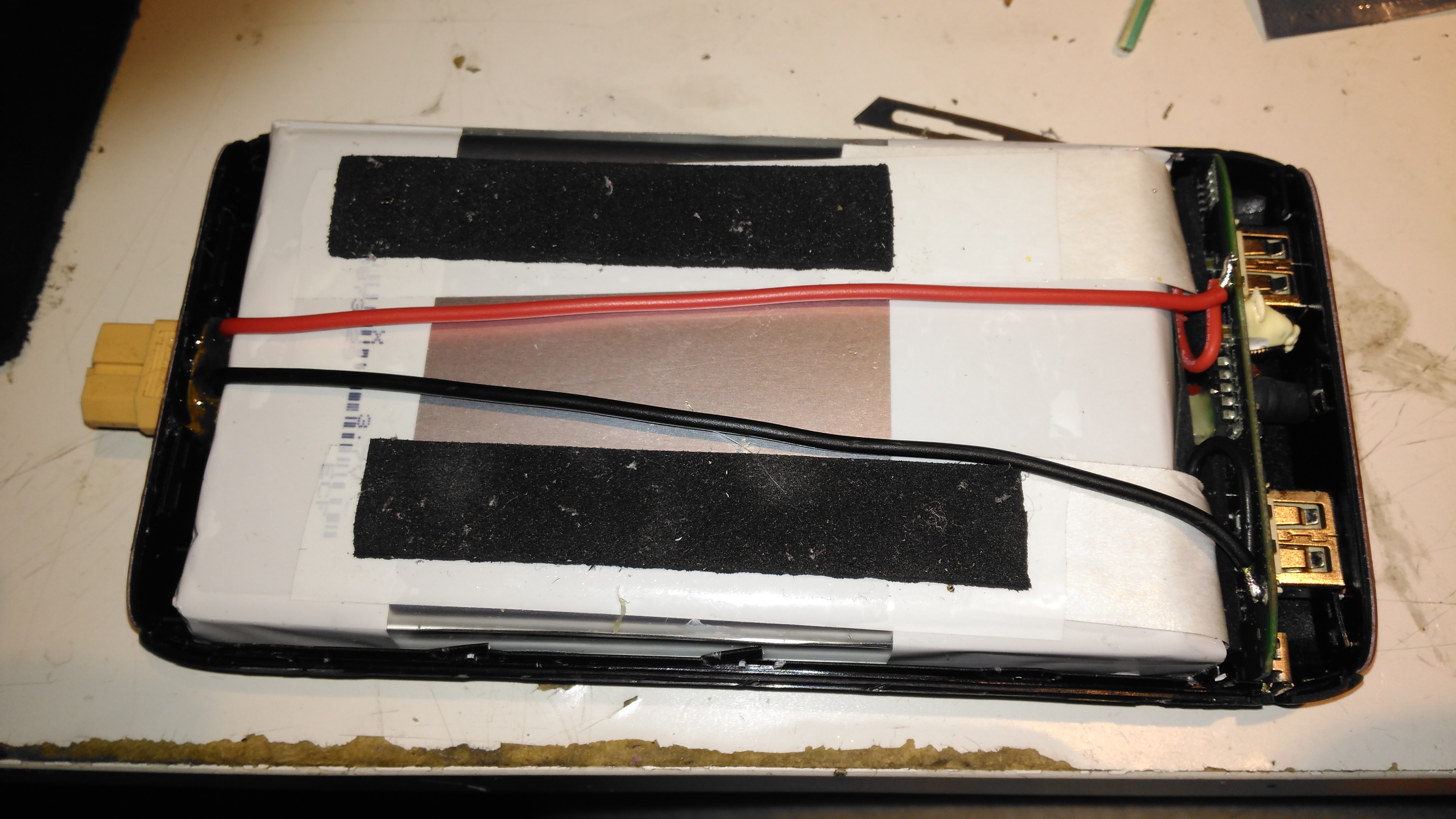
XT60 Battery Connector
The only issue with powerbanks this large is the amount of time they require to recharge themselves – at this unit’s maximum of 2A through the µUSB port, it’s about 22 hours! Here I’ve fitted an XT60 connector, to interface to my Turnigy Accucell 6 charger, increasing the charging current capacity to 6A, and reducing the full-charge time to 7 hours. This splits to 3A charge per cell, and after some testing the cells don’t seem to mind this higher charging current.
Battery Connector Wiring
The new charging connector is directly connected to the battery at the control PCB, there’s just enough room to get a pair of wires down the casing over the cells.
A few months ago I did a teardown on this Anker PowerPort Speed 5 USB charger, but I didn’t get round to detailing the conversion to 12v I had to do, so I’ll get to that now I’ve got a couple more to convert over.
Power Module
Here’s the internals of the Anker charger once I’ve removed the casing – which like many things these days, is glued together. (Joints can be cracked with a screwdriver handle without damaging the case). There’s lots of heatsinking in here to cool the primary side switching devices & the pot core transformers, so this is the first thing to get removed.
Heatsink Removed
Once the heatsink has been removed, the pot core transformers are visible, wrapped in yellow tape. There’s some more heatsink pads & thermal grease here, to conduct heat better. The transformers, primary side switching components & input filter capacitor have to go.
Primary Side Components Removed
Here’s the PCB once all the now redundant mains conversion components have been deleted. I’ve left the input filtering & bridge rectifier in place, as this solves the issue of the figure-8 cable on the input being reversible, polarity of the input doesn’t matter with the bridge. I’ve removed the main filter capacitor to make enough room for the DC-DC converters to be fitted.
Tails Installed
Installing the tails to connect everything together is the next step, this charger requires two power supplies – the QC3 circuits need 14.4v to supply the multi-voltage modules, the remaining 3 standard ports require 5v. The DC input tails are soldered into place where the main filter capacitor was, while the outputs are fitted to the spot the transformer secondary windings ended up. I’ve left the factory Schottky rectifiers in place on the secondary side to make things a little more simple, the output voltages of both the DC-DC converters does need to be increased slightly to compensate for the diode drops though. I’ve also bypassed the mains input fuse, as at 12v the input current is going to be substantially higher than when used on mains voltage.
DC-DC Converters Installed
With a squeeze both the boost converter & the buck converter fit into place on the PCB.
This is a part of the boat that hasn’t really had much TLC since we moved aboard, and finally it’s completely succumbed to corrosion, opening a rusty hole into the engine space below. I’ve already used a grinder to remove the rest of the locker – and even this had corroded to the point of failure all around the bottom just above the welds. The bulkhead forming the rear of the locker has also corroded fairly severely, so this will be getting cut out & replaced with a new piece of steel.
This was originally a 1/8″ plate, but now it’s as thin as foil in some places, with just the paint hiding the holes.
Replacement Steel
I’ve cut out as much of the corroded deck plate as possible – it’s supported underneath by many struts made of angle iron, and got the new 3mm replacement tacked in place with the MIG. I’ve not yet cut out the rotten section on the bulkhead, this will come after we’ve got the steel cut to replace it, as electrical distribution is behind this plate – I’d rather not have weather exposure to the electrical systems for long! Unfortunately more corrosion has showed itself around the edges of the old locker:
Thin Steel
Around the corner the steel has pretty much totally failed from corrosion coming from underneath – applying welding heat here has simply blown large holes in the steel as there’s nothing more than foil thickness to support anything.
Some more extensive deck replacement is going to happen to fix this issue, more to come when the steel comes in!
Since the engine & hydrostatic transmission were installed in the boat a few years back, the hydraulic oil cooler has been in the same fresh water circuit as the engine’s water cooling system, however this has been causing some heat issues with the engine & hydraulic system under a heavy load, such as when I’m using the onboard generator to run the welding gear. The hydraulic oil temp would rise to over 80°C during the course of a long day’s cruising – such temperatures will degrade the oil very quickly, and in turn will cause premature wear of the very expensive hydraulic pumps. (Not to mention increasing the requirement for hydraulic oil changes, which are very expensive). The engine oil has been cooled by a standard automotive oil radiator, with air forced over the matrix by two large fans. This is also pretty inefficient, so another cooler will be added to replace the automotive one.
This cooling requirement is caused by the inefficiency of hydraulic systems – a simple variable displacement piston pump driving a bent-axis piston motor has an overall efficiency of roughly 80%. Given our engine’s max power of 76HP (56.7kW), this gives an energy loss of 15.2HP (11.33kW) at maximum power. This extra heat overloaded the skin tank, resulting in a cooling system that didn’t really work all too well once the engine was hot.
To solve this issue, we’ve decided to run a raw water circuit using the canal to remove the waste heat from the hydraulic system & engine oil, putting less of a heat load on the skin tank to bring the temperatures down to something reasonable. The image above show the system at running temperature after I installed the monitoring instruments. The top gauge is measuring engine oil temperature, at the point where it’s being fed to the bearings. The bottom one is measuring hydraulic oil temperature.
The engine oil temperature does have to be higher than any other cooling circuit on board, to boil off any condensate from the cylinders. Overcooling the oil in the sump will eventually cause sludging as the oil tries to absorb the resulting water. I’m aiming for a system temperature in the engine oil circuit of 95°C-120°C when the engine is under load & at operating temperature.
Raw Water Suction
Water from the canal is drawn from a skin fitting installed at the last drydock visit, pulling water through a strainer to remove all the large bits of muck. The large slotted screen on the suction skin fitting keeps larger objects out of the intake.
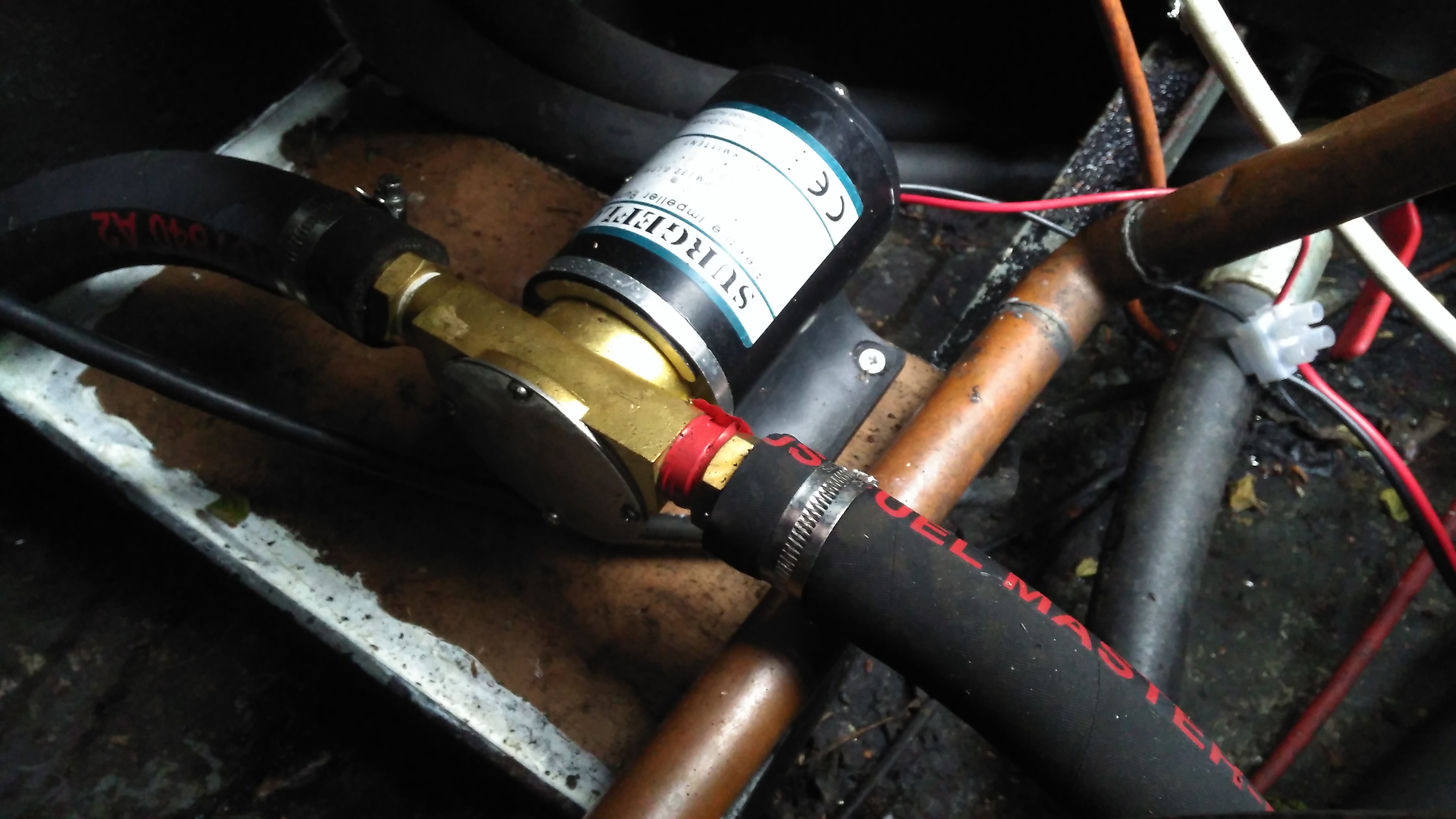
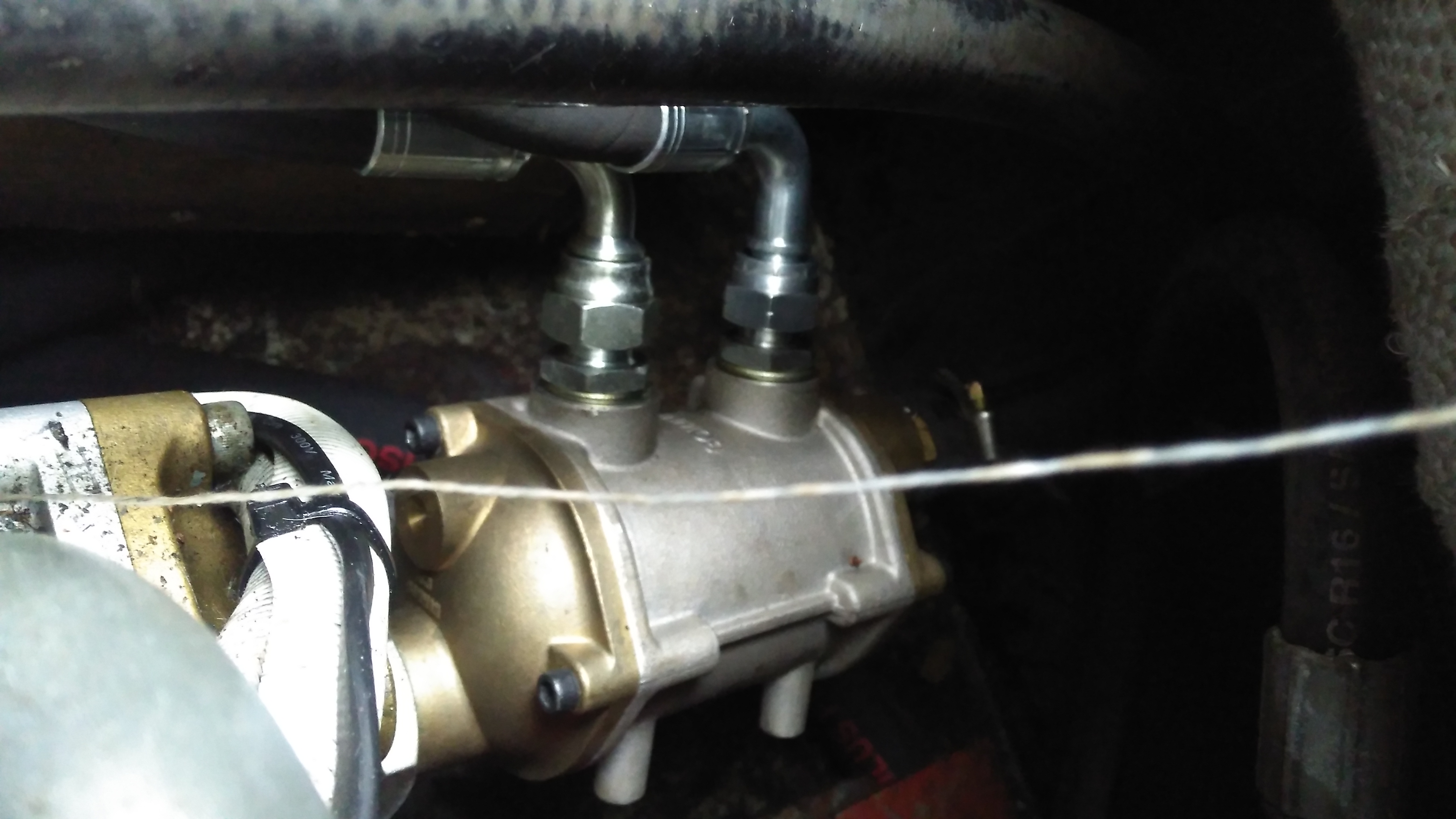
Raw Water Pump
A flexible impeller pump provides the power to move water through the system, in this case about 25L/Min. This pump is a cheap copy of a Jabsco pump from eBay. So far it’s been pretty reliable.
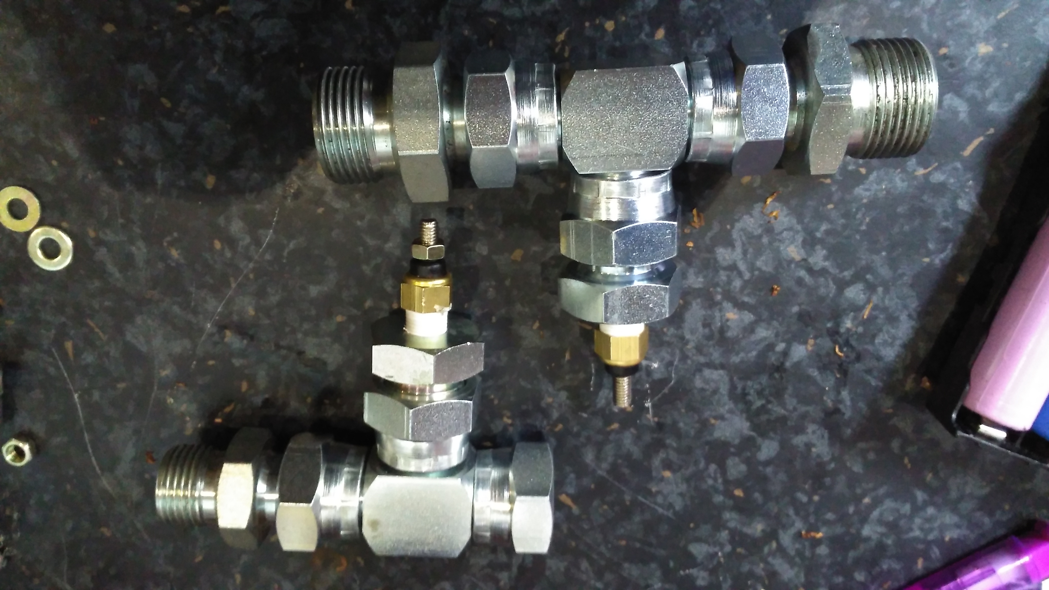
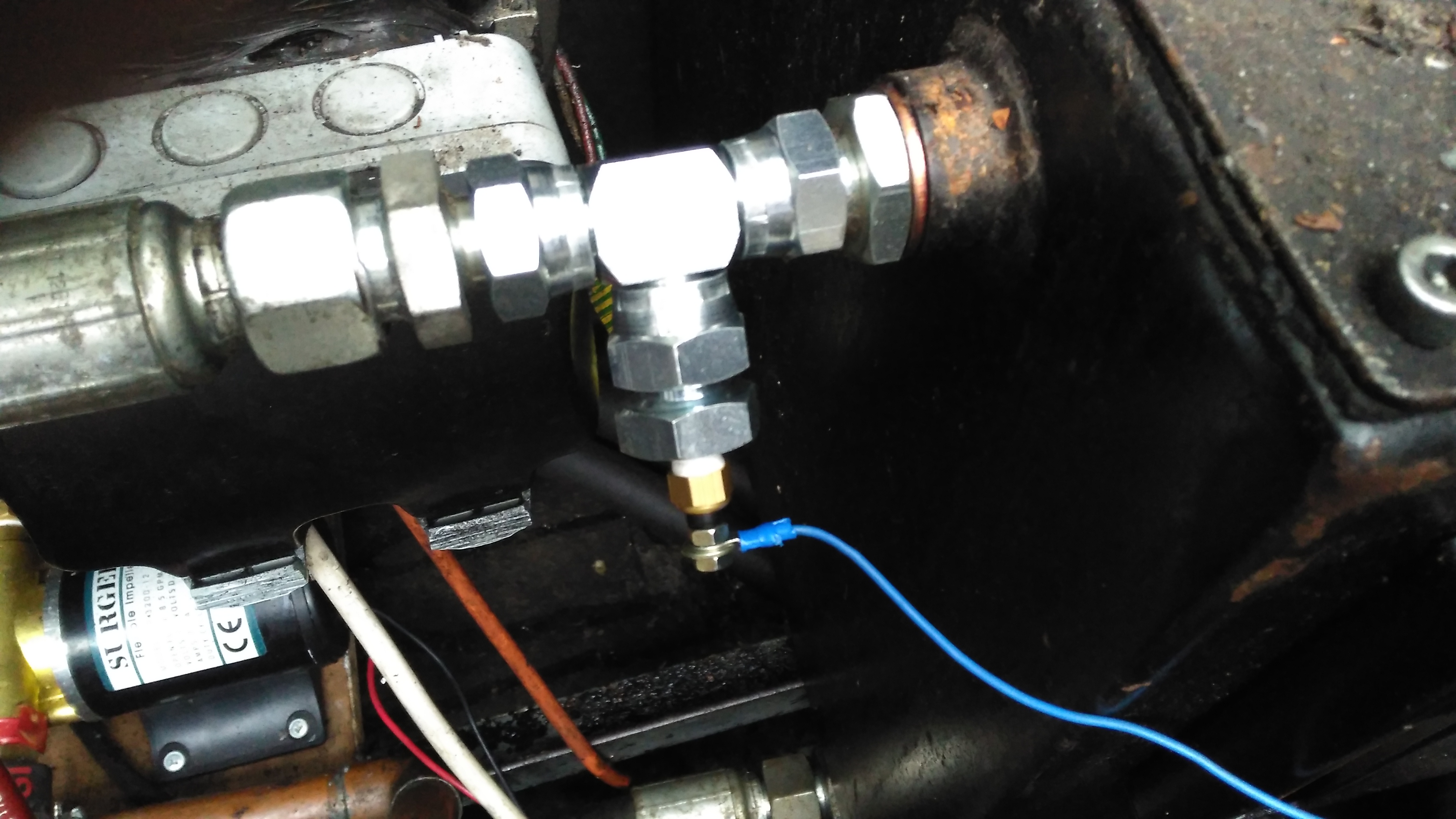
Temperature Senders
The temperature senders are standard automotive parts, and some adaptors were required to graft them into the oil lines of both systems. The senser’s 1/8″ NPT threads are here fitted into 1/2″ BSP hydraulic fittings.
Hydraulic Temperature Sender
Here’s the hydraulic oil sender installed in the drain line from the main propulsion pump, this should give me a pretty good idea of the temperature of the components in the system, the sender is earthed through the steel hydraulic oil tank.
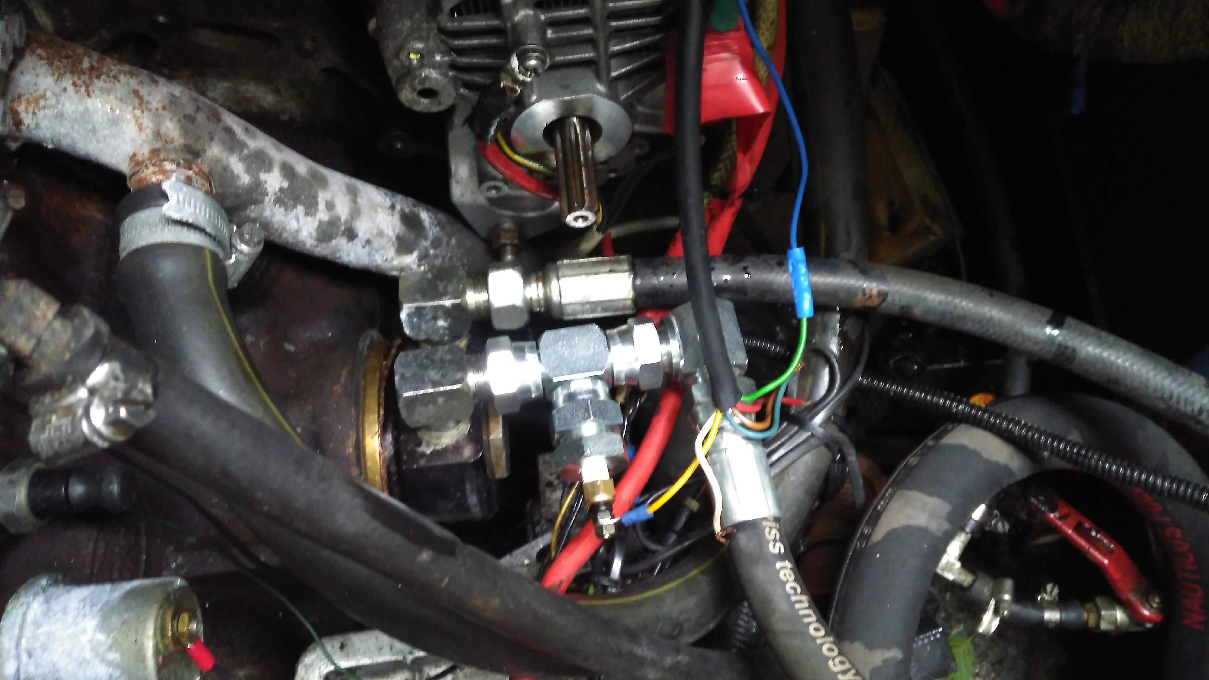
Engine Oil Temperature Sender
The oil temperature sender is installed in the return line to the engine from the heat exchanger. This is measuring the oil temperature the bearings in the engine are being fed with.
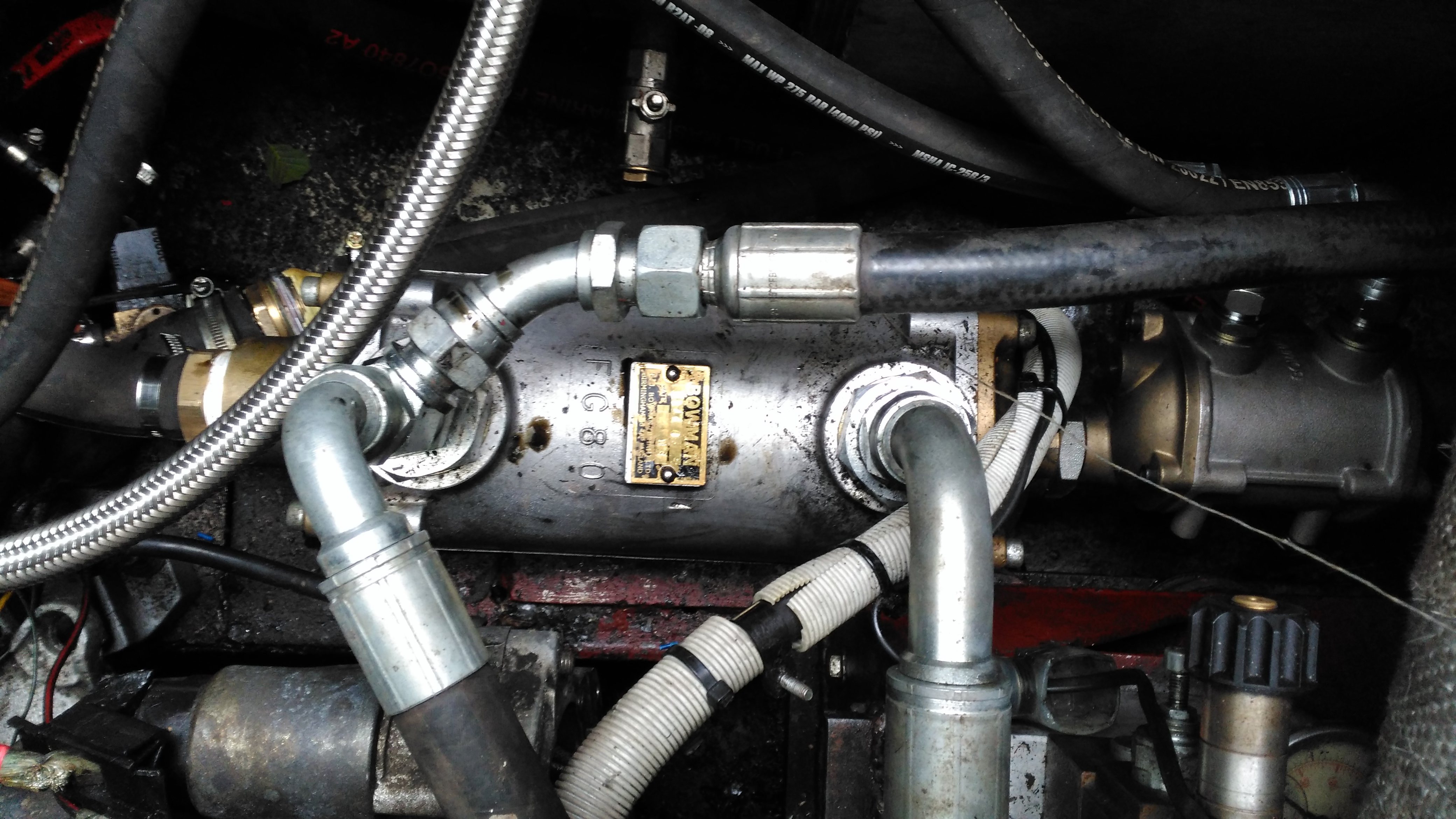
Hydraulic Oil Heat Exchanger
The stack of heat exchangers is located on the starboard side of the engine bay, the large one here is cooling the hydraulic oil, the auxiliary pump is continually circulating the oil from the tank through this, then into the return filter on the top of the tank.
Engine Oil Heat Exchanger
The engine oil is fed through this much smaller heat exchanger mounted on the back of the large hydraulic cooler, the last in the circuit before the water is discharged back overboard through a skin fitting.
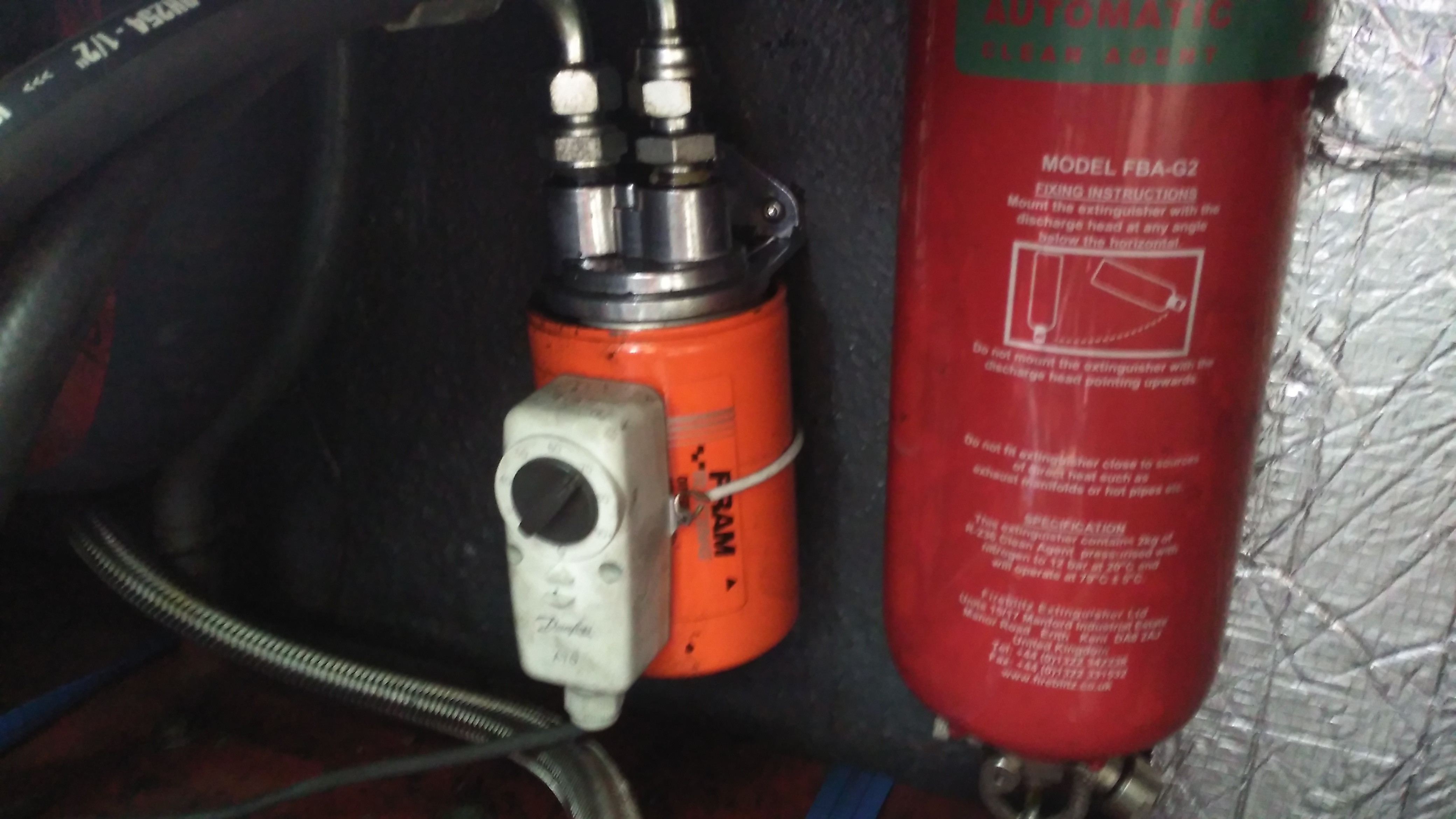
Remote Oil Filter
As we’ve got the diverter block on the side of the engine where the oil filter should be, a remote oil filter is fitted above the fuel tank. The thermostat strapped on operates the main engine bay ventilation fans, switching them on once the engine oil reaches 60°C.
As quickly as it came round again, the festival is over. The yearly photos are over here, along with some extra content in the form of Demolition Download videos – brought to us by Battle Heritage UK! Enjoy.
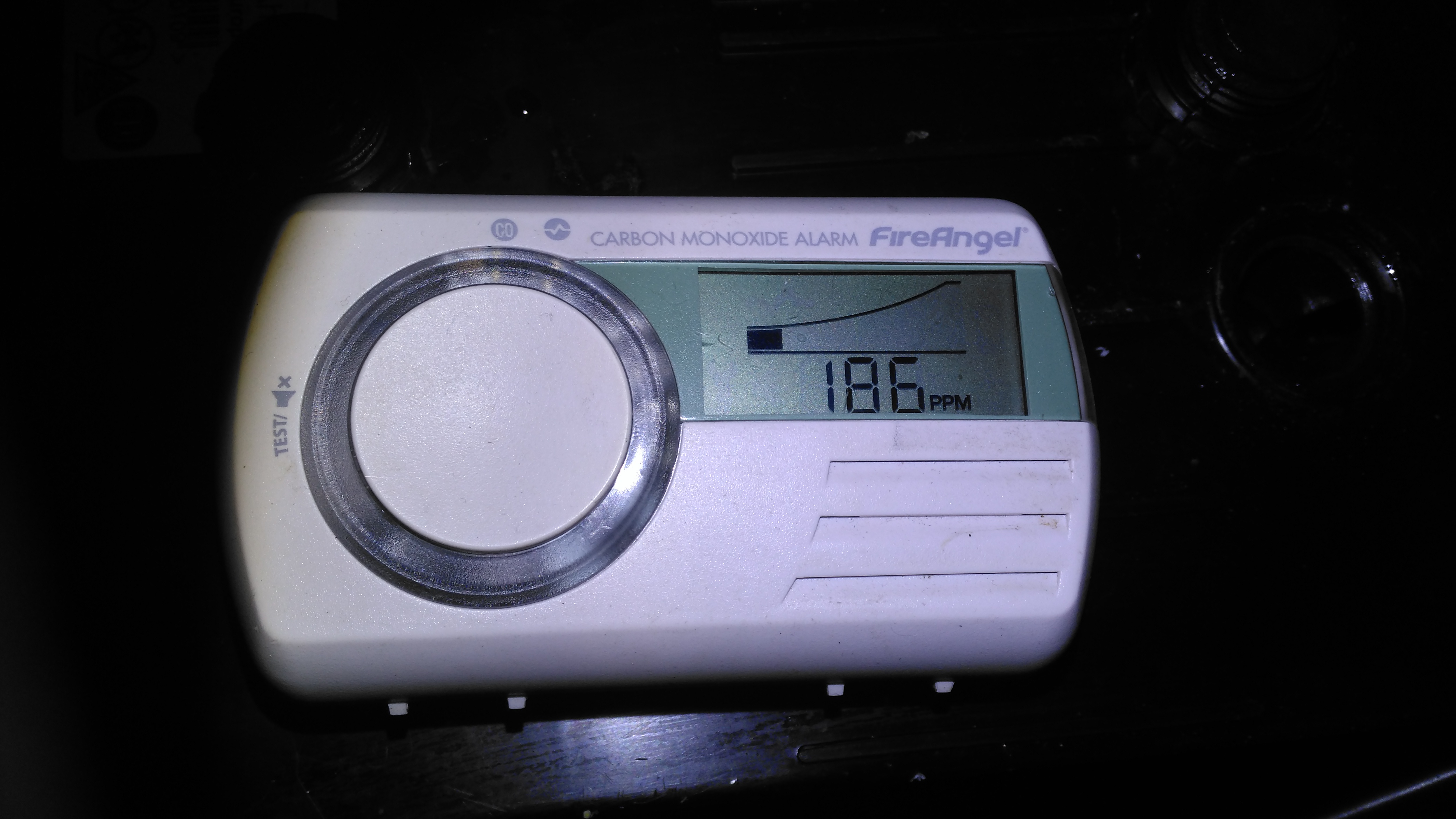
Here’s something different – below is a standard domestic carbon monoxide alarm, (I did a teardown of the same detector here), but in this case it’s not detecting any carbon monoxide, but another gas in the surrounding atmosphere. We recently had an issue with these detectors on board the boat, the alarms were sounding in the middle of the night, at ridiculous levels displayed, with no fuel-burning appliances running! While it didn’t become obvious at the time, the gas being detected was hydrogen, given off from the house battery bank while they were on charge.
CO Detector
I have long been aware of the fact that electrochemical gas sensors have some cross-sensitivity, and sensors are available that are specifically designed to not respond to other gases (hydrogen in particular, as this gas is actually part of the sensor reaction. Much more information about the subject is over here). I’ve no doubt these more industrial grade sensors are much more expensive than the cheap kind used in domestic alarms though, not to mention there aren’t usually massive lead-acid battery banks in houses, so the concept of having hydrogen in the air doesn’t usually happen.
However, I’ve seen plenty of these exact type, and other types of the same brand used on boats. The user manual for this particular alarm doesn’t mention the possibility of cross-sensitivity though, and this could lead someone to doubt their alarm is working correctly, and to stop trusting it or remove it entirely due to false triggering.
As I’ve not been able to find any data on the sensor used in this detector, I don’t know how sensitive it is to hydrogen, the image above was taken with an alarm placed directly over the cell opening of a large lead-acid battery on charge at 14.7v to deliberately cause some gassing. This was the highest reading obtained, the detector didn’t take long to respond either. As the gas mix coming out of the cell is 2:1 H²/O² this reading is clearly low, but it’s still plenty enough to sound the alarm within a few minutes.
For us on boats, with potentially explosive gas mixtures being able to gather this cross sensitivity is potentially a good thing – the alarm made sure we were well aware of something going wrong before a dangerous concentration was present. (Hydrogen is flammable in air between 4% & 75%).
To prevent this happening in future, I’ll be installing some forced ventilation into the battery compartment, triggered by a hydrogen sensor. More to come on this soon!
It’s been a bit quiet around here for a couple of weeks, as it’s the run-up to Download Festival here in the UK, so I’ve been busy sorting everything out for that. Just in time a new order has come in!
Due to a small accident with the old Maplin torch from a while back, (turns out they don’t float when dropped in the canal – ooops), a new one was sourced. Maplin is very expensive considering the imported crap they peddle these days, so I figured eBay would be the best bet for cheap imported crap 😉 This unit came with a few accessories, so I’ll start with the torch itself.
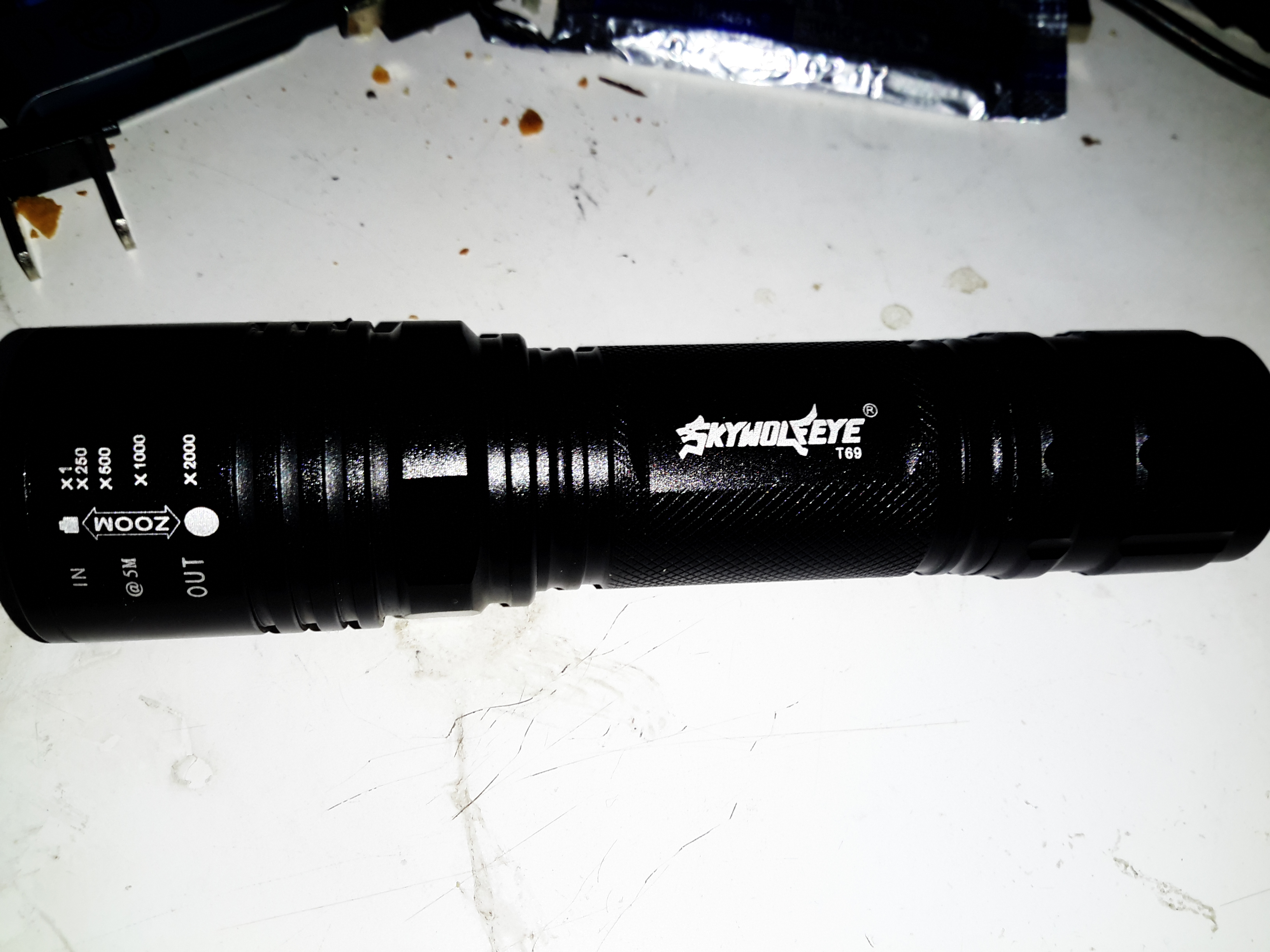
18650 Torch
This is an aluminium unit, and does feel quite well built for the price, but it does have a few disappointing things. The lens assembly at the front is movable so focus the beam – the range goes from wide flood to a very small spot.
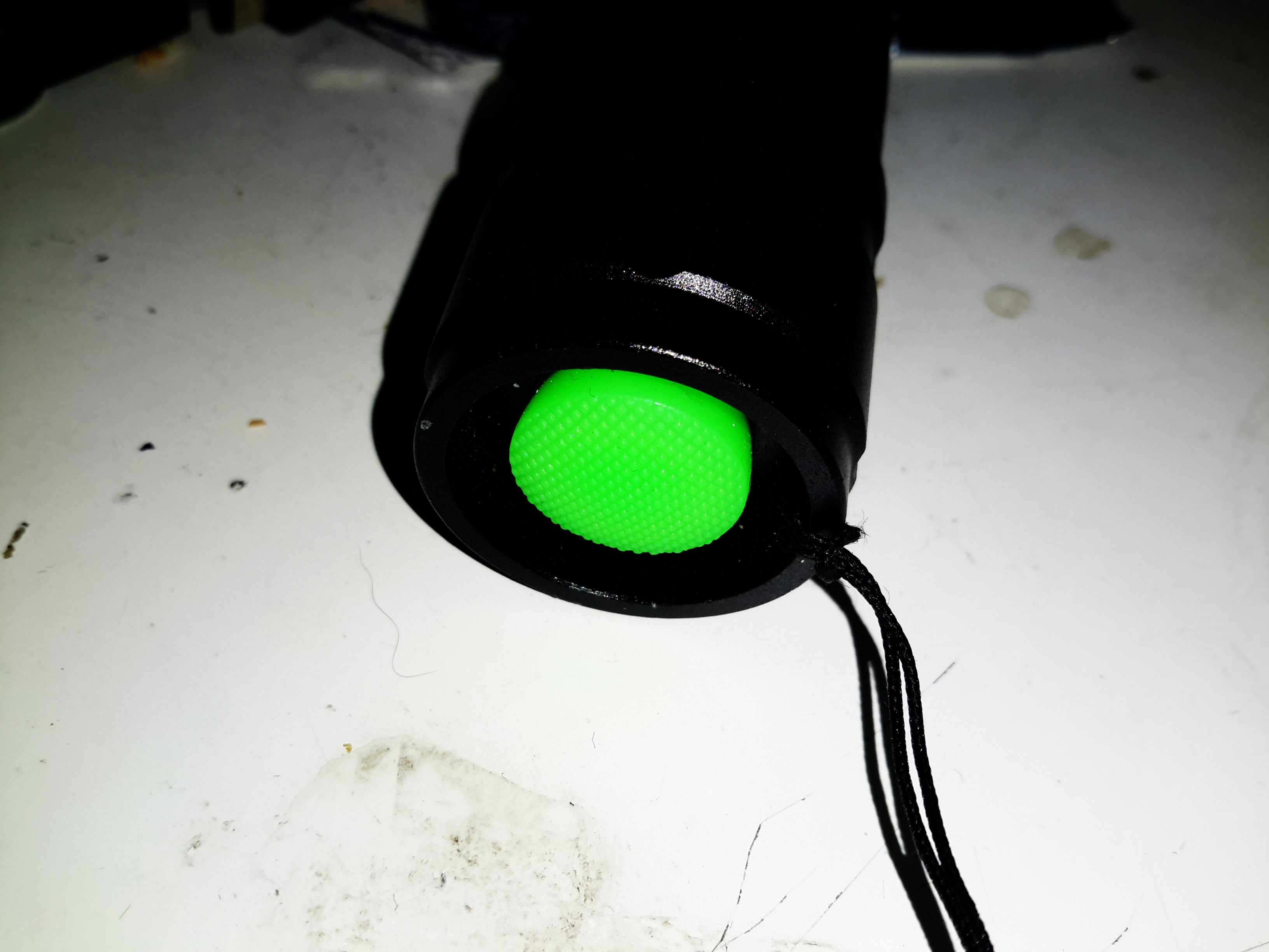
Power Switch
The power switch on this torch is at the back on the cap, covered by this obscenely brightly coloured cap.
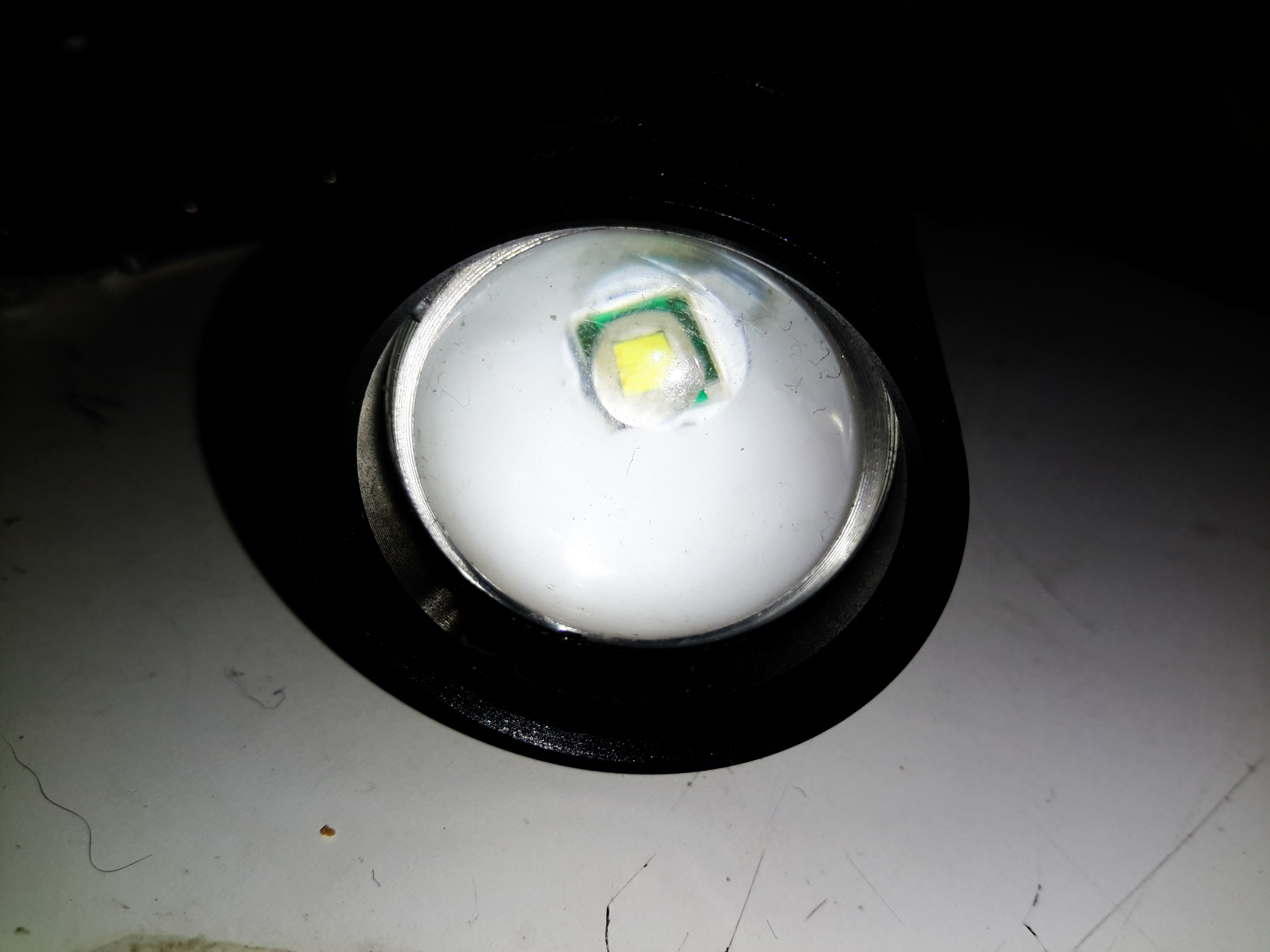
Lens Assembly
The lens is a simple plastic moulding, but it produces a nice wide beam.
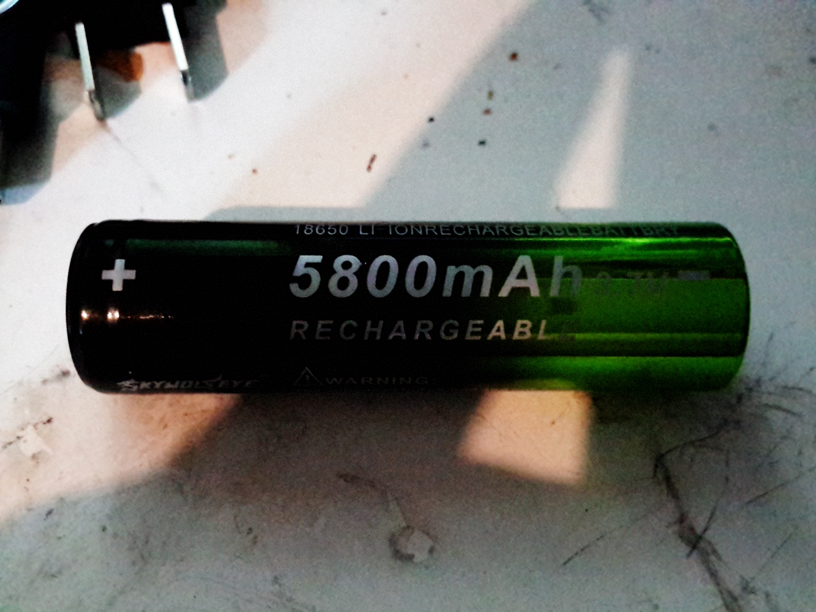
Enthusiastic Numbers
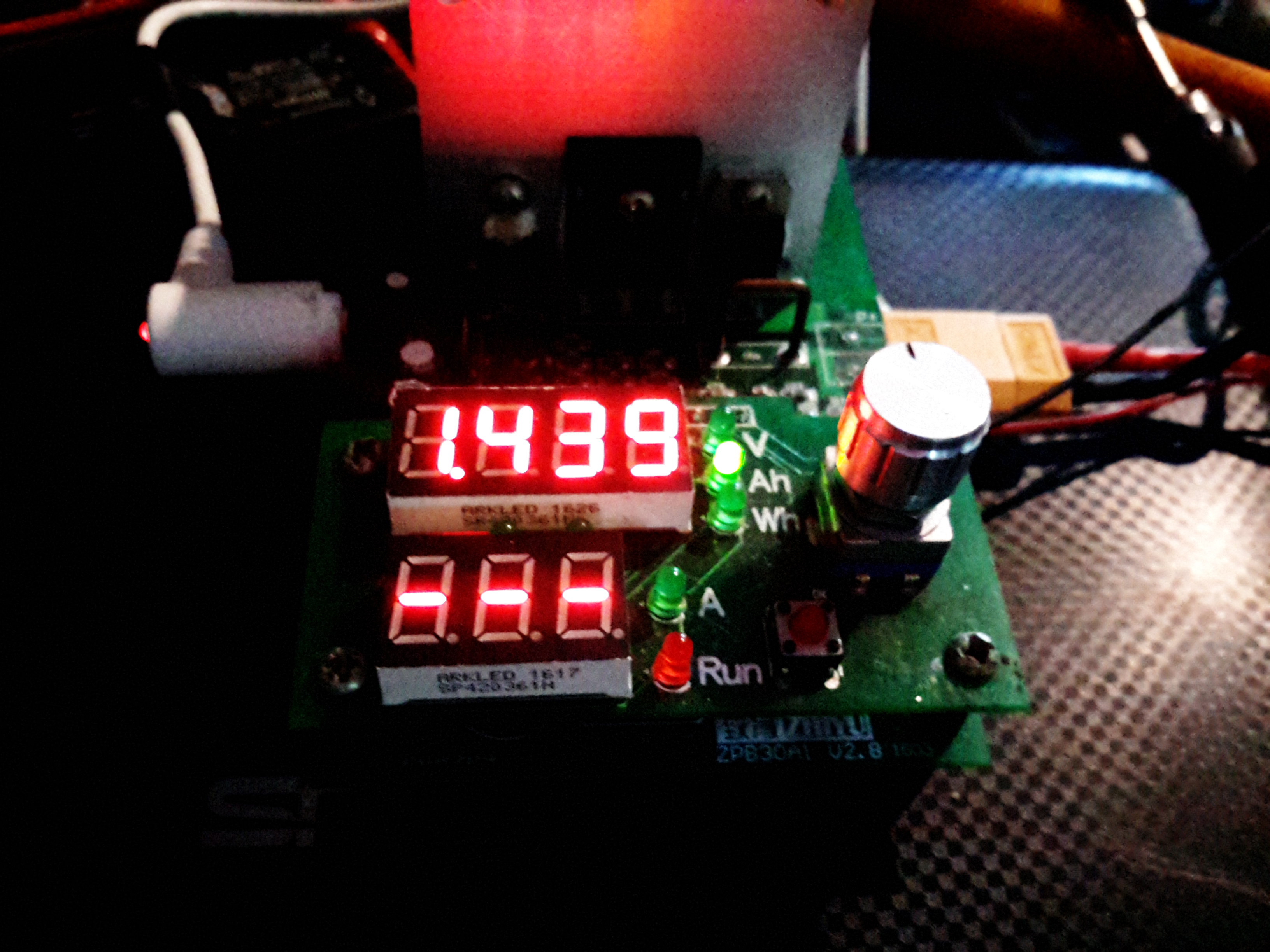
On to the battery supplied – this claims to be a 5.8Ah 18650 cell, which as far as I’m aware do not exist. I’m always dubious of lithium-ion cells from eBay, the Chinese seem to be well into a race to put the biggest numbers that will fit on the label. (I’ve even seen a USB powerbank claming to have 100Ah of capacity!). The largest capacity cells I have at present are LG HG2 18650s, and those are only rated at 3Ah a piece. They’re also relatively expensive.
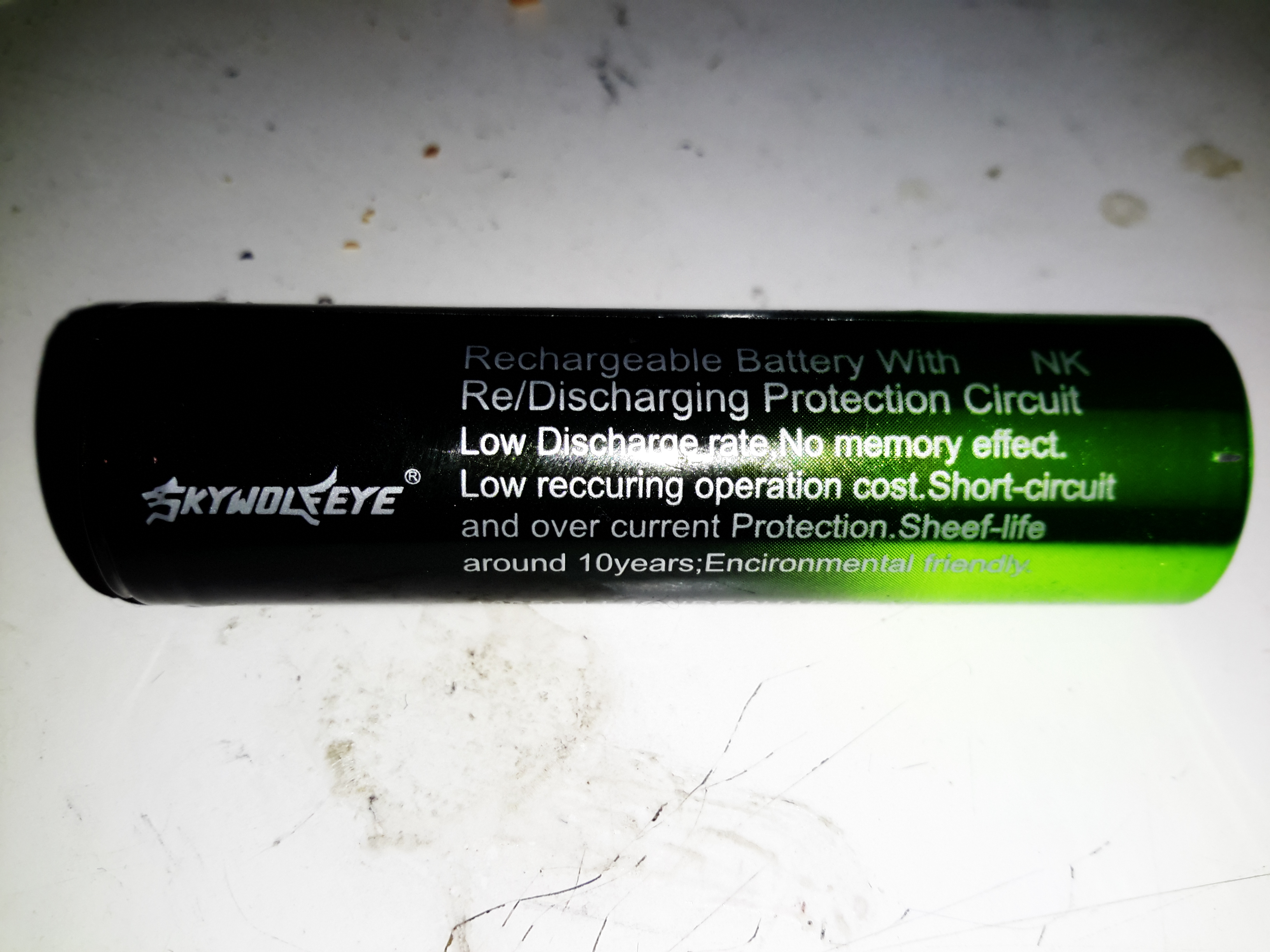
Label
The manufacturer couldn’t even get the label spelling correct! Although they do apparently have a 10 year “sheef” life. Never seen that from an 18650 either. They tend to discharge on their own if left unused in about 12 months. I wouldn’t like to think of what the self-discharge rate of these dodgy things is, and I don’t intend to keep them to find out either!
Battery Capacity
After a quick blast on the charger to top them up, on the discharge tester they go! This test was conducted at 1A, and this now shows the true capacity of 1.439Ah, which is honestly better than I was expecting. Already having high quality cells I wasn’t fussed about this aspect of the purchase, I knew these cells would end up in the bin.
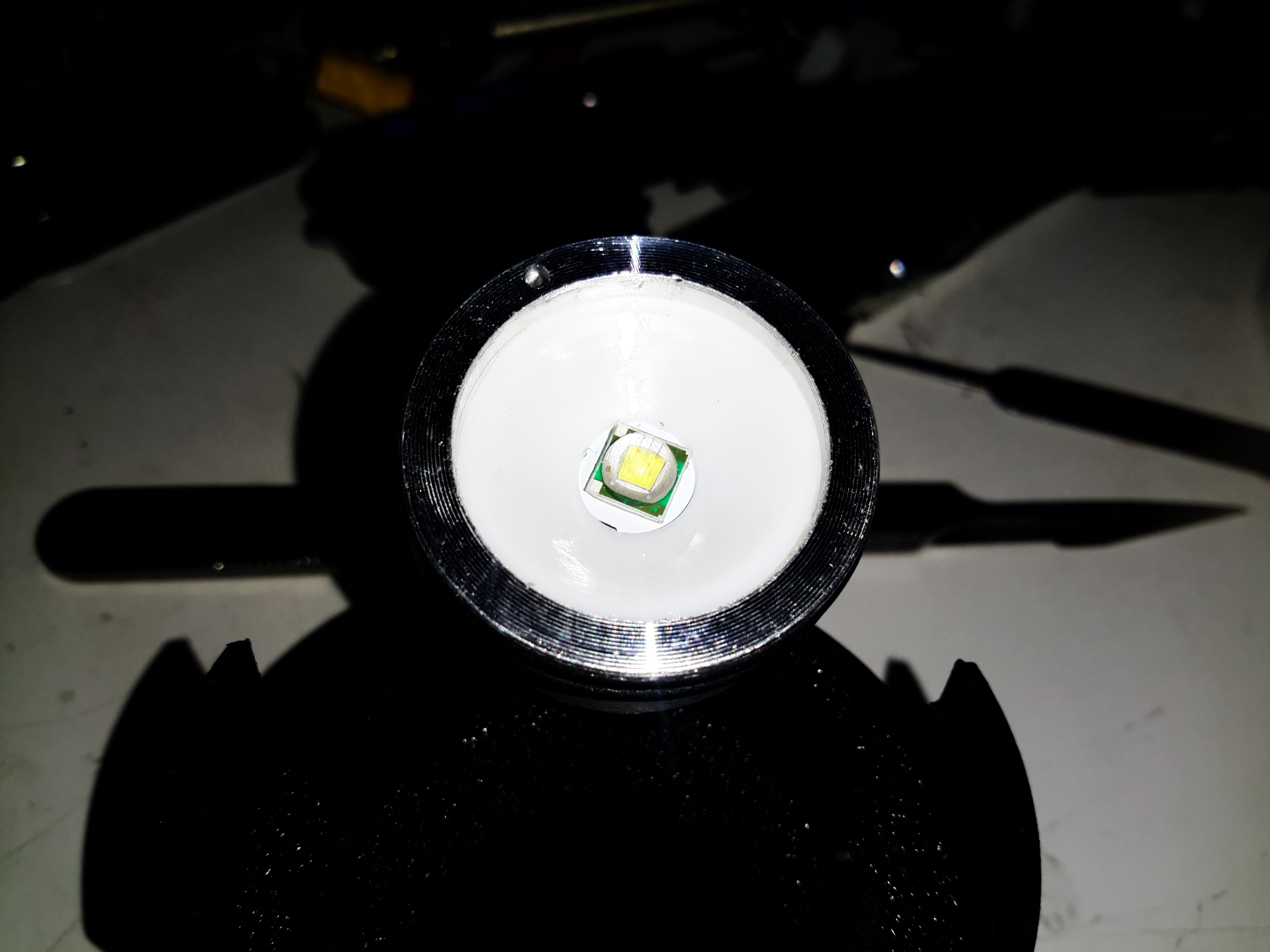
LED Module
Unscrewing the lens housing at the front gives access to the LED module – this is a Cree XM-L die in here, although it might not be a genuine Cree (or possibly a factory reject). The LED housing is aluminium, the LED uses this as a heatsink.
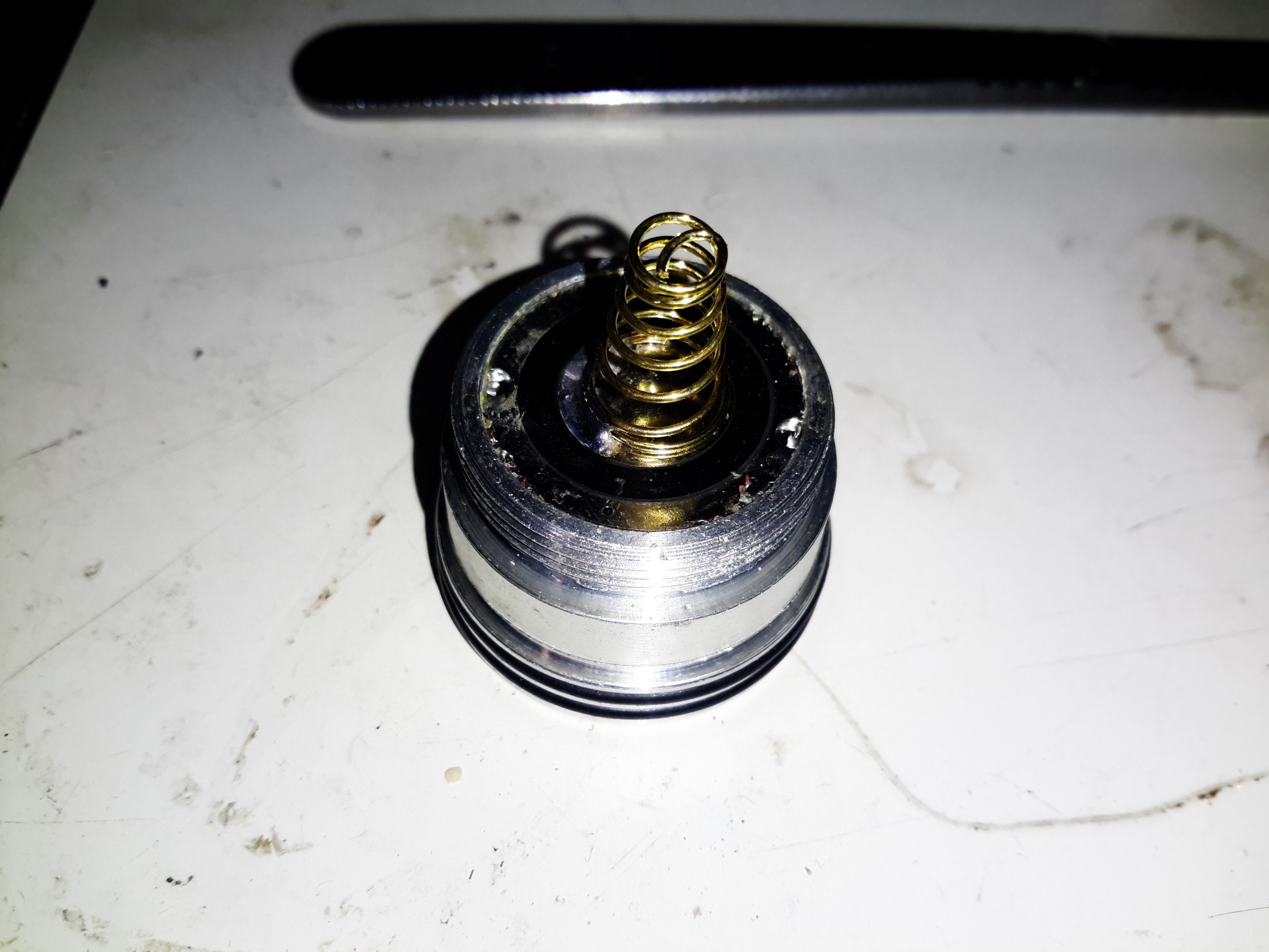
Positive Contact Spring
Nothing special about the back of the module after it’s been unscrewed from the barrel. There’s a couple of O-Rings to seal the sliding lens assembly, I lubricated these with some silicone grease to try & make the housing somewhat splashproof.
Control PCB
The control PCB is pulled out of the housing to reveal the circuitry. The LED is controlled by a SOT-23 mode IC & a SO-8 MOSFET. There’s nothing complex about the LED current limiting, just a bunch of SMD resistors in parallel to set the limit. This torch, like 99% of Chinese import torches from eBay, has a multi-mode IC with SOS & strobe. I don’t need this crap, and it’s easily bypassed.
Modifications
Here I’ve desoldered the MOSFET from the board & jumped across it’s drain & source connections, converting the torch to simple ON/OFF control.
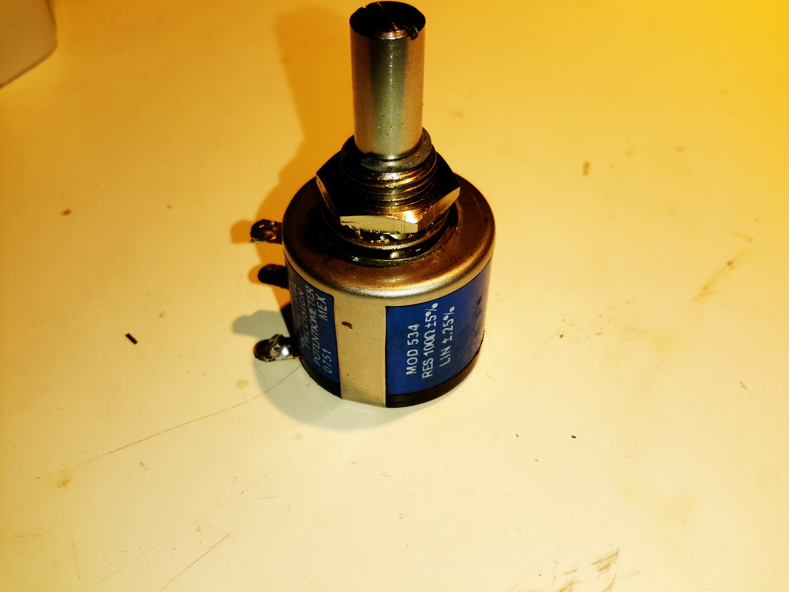
I recently used a Vishay Spectrol Precision 10-turn potentiometer in my latest PSU project, and since these clip together instead of being ultrasonically welded like Bourns potentiometers, I decided to do a quick teardown for the blog. I didn’t find much in the way of how these pots worked from a search, so here we go!
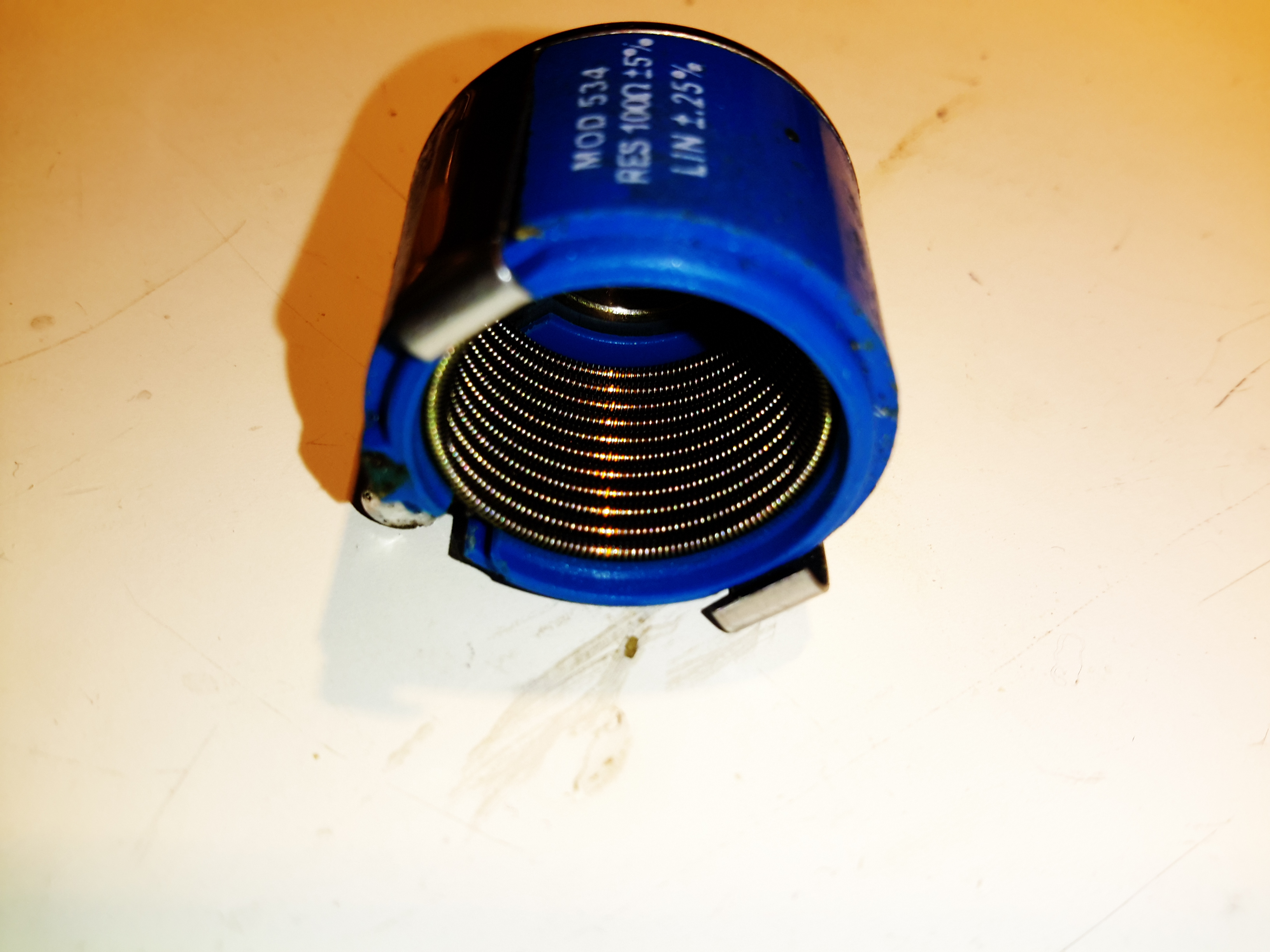
Vishay Spectrol Precision 10-Turn
Here’s a pot of the same spec as I used in the previous project, again from my random used junk bin. This is a 100Ω, 5% wirewound potentiometer. The shaft is secured in the centre bushing with a snap ring, this is easily removed with a pair of needlenose pliers.
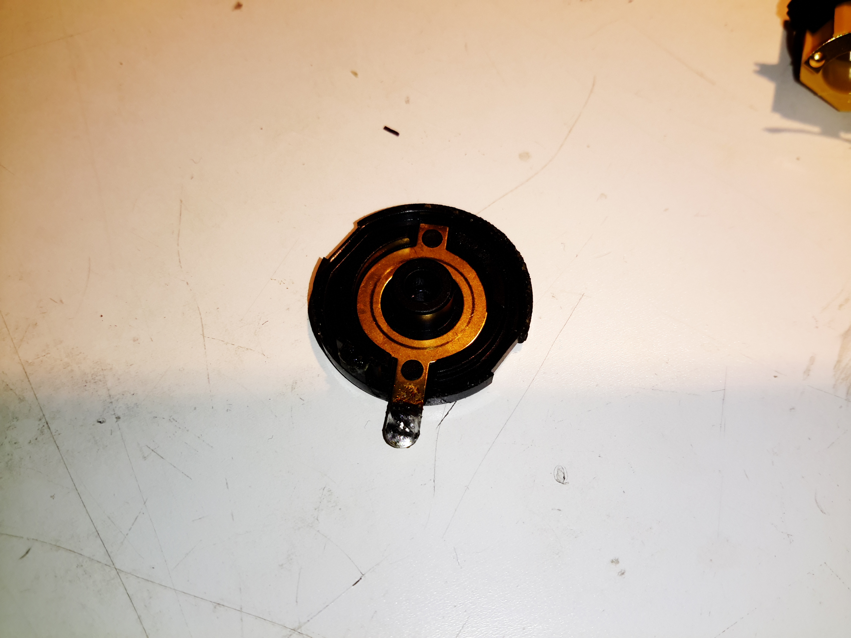
Wiper Stationary Contact
After unclipping the back cover, the stationary part of the wiper contact is visible in the back plastic cover.
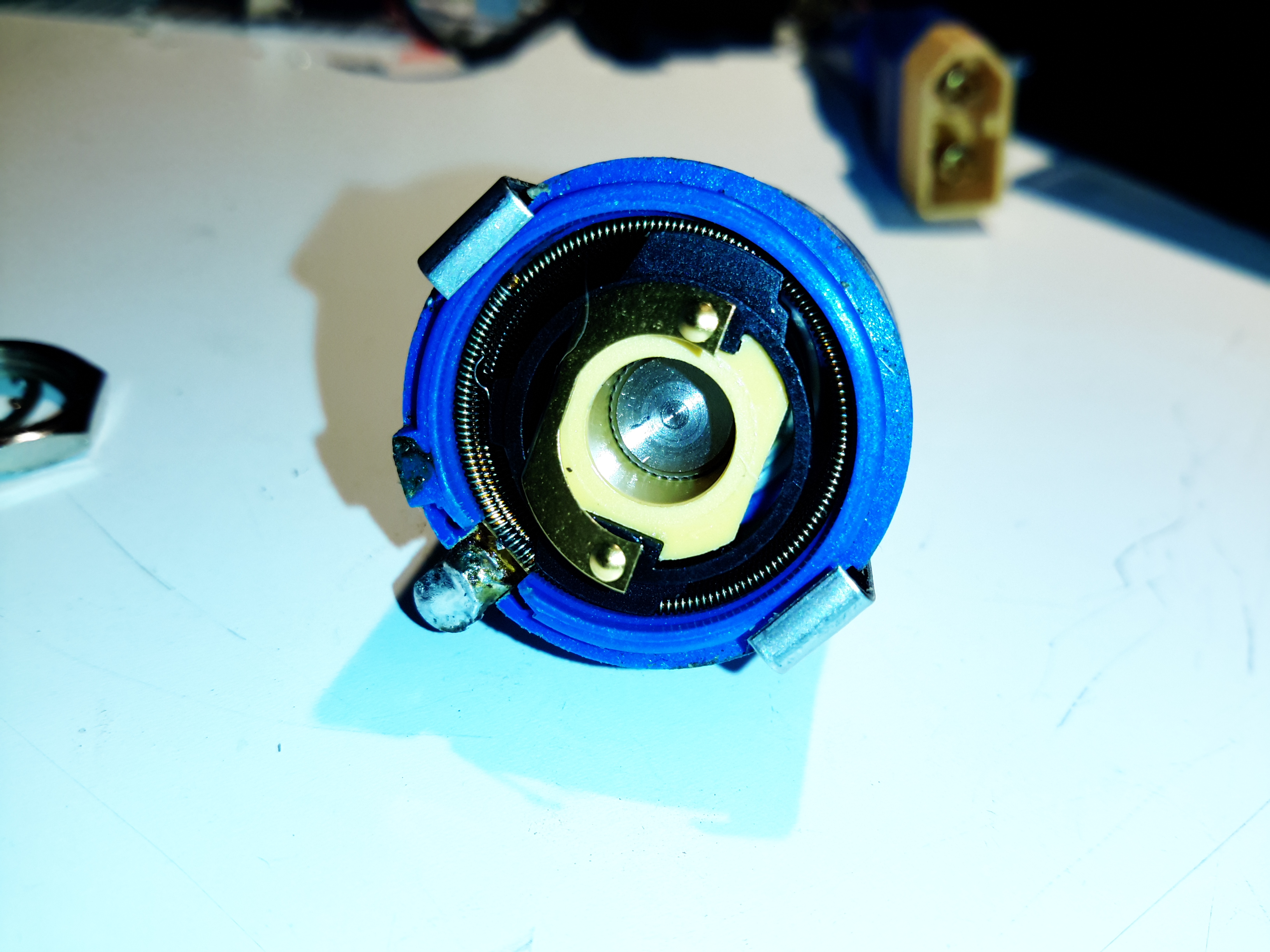
Back Cover Removed
Inside the back of the potentiometer shows the inner workings. These devices have a large helical winding of resistance wire around the inner diameter of the casing, the wiper tracks this helix as the potentiometer is turned.
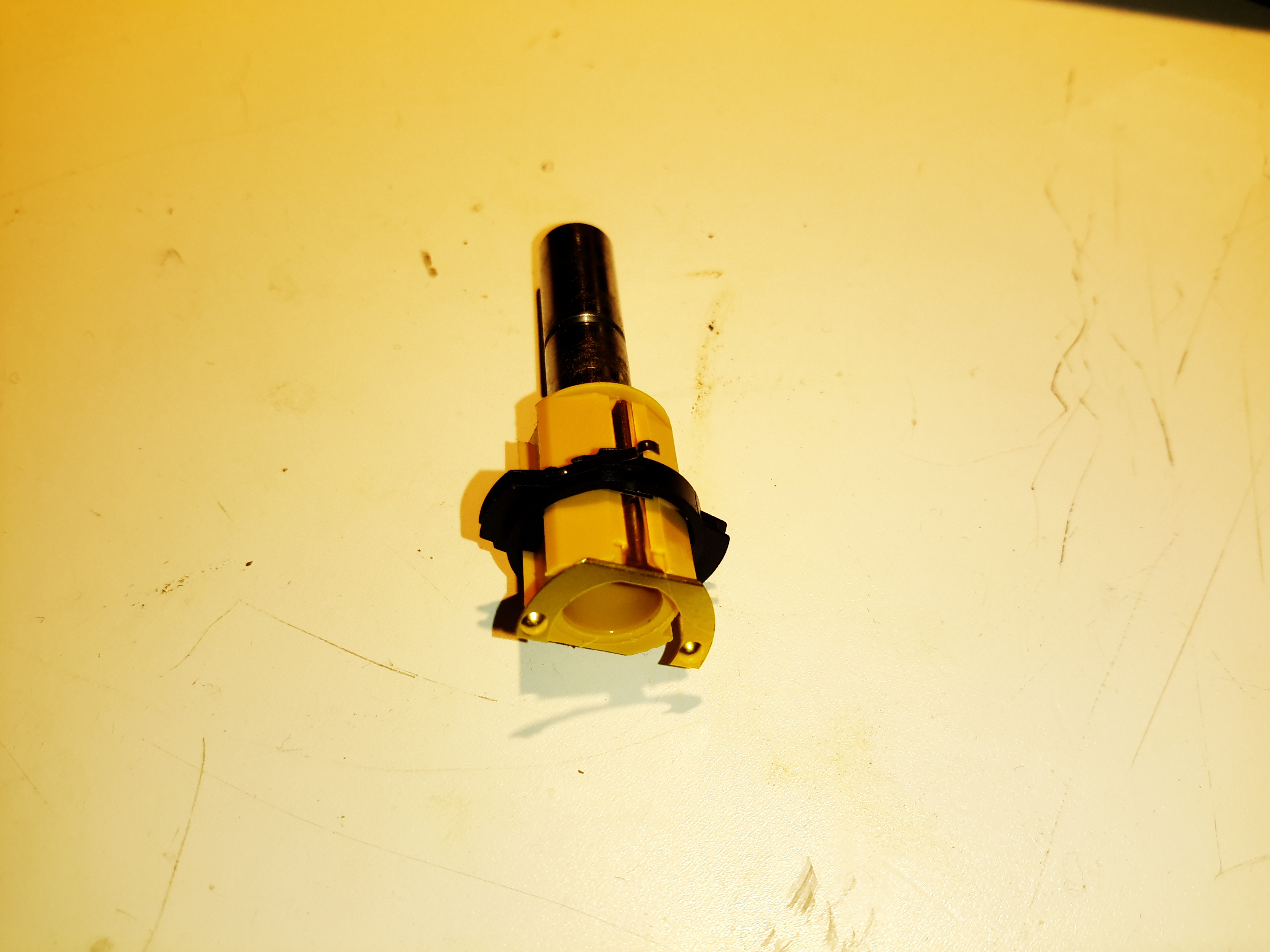
Centre Contact & Shaft
As the wiper must move axially as it winds around the spiral of resistance wire, the contact is mounted on a pair of guides so it can slide back & forth. The electrical connection is made via another spring contact that runs down the side of the plastic shaft insert. Two notches cut into the black plastic wiper frame engage with the round profile of the resistance winding like a screw into a nut, keeping the wiper in perfect alignment as it travels the full length of the winding. I suspect all these moving contacts are made of Beryllium Copper in this rather expensive component as this alloy is very flexible, as well as being a very good electrical conductor.
Resistance Winding
With the centre shaft & it’s wiper contact removed from the shell, the helix of resistance wire can be seen inside. Oddly, the former the resistance wire is wound around appears to be metal, possibly copper, but to keep the entire thing from shorting itself out this must be coated in insulation.
Tip Jar
If you’ve found my content useful, please consider leaving a donation by clicking the Tip Jar below!
All collected funds go towards new content & the costs of keeping the server online.