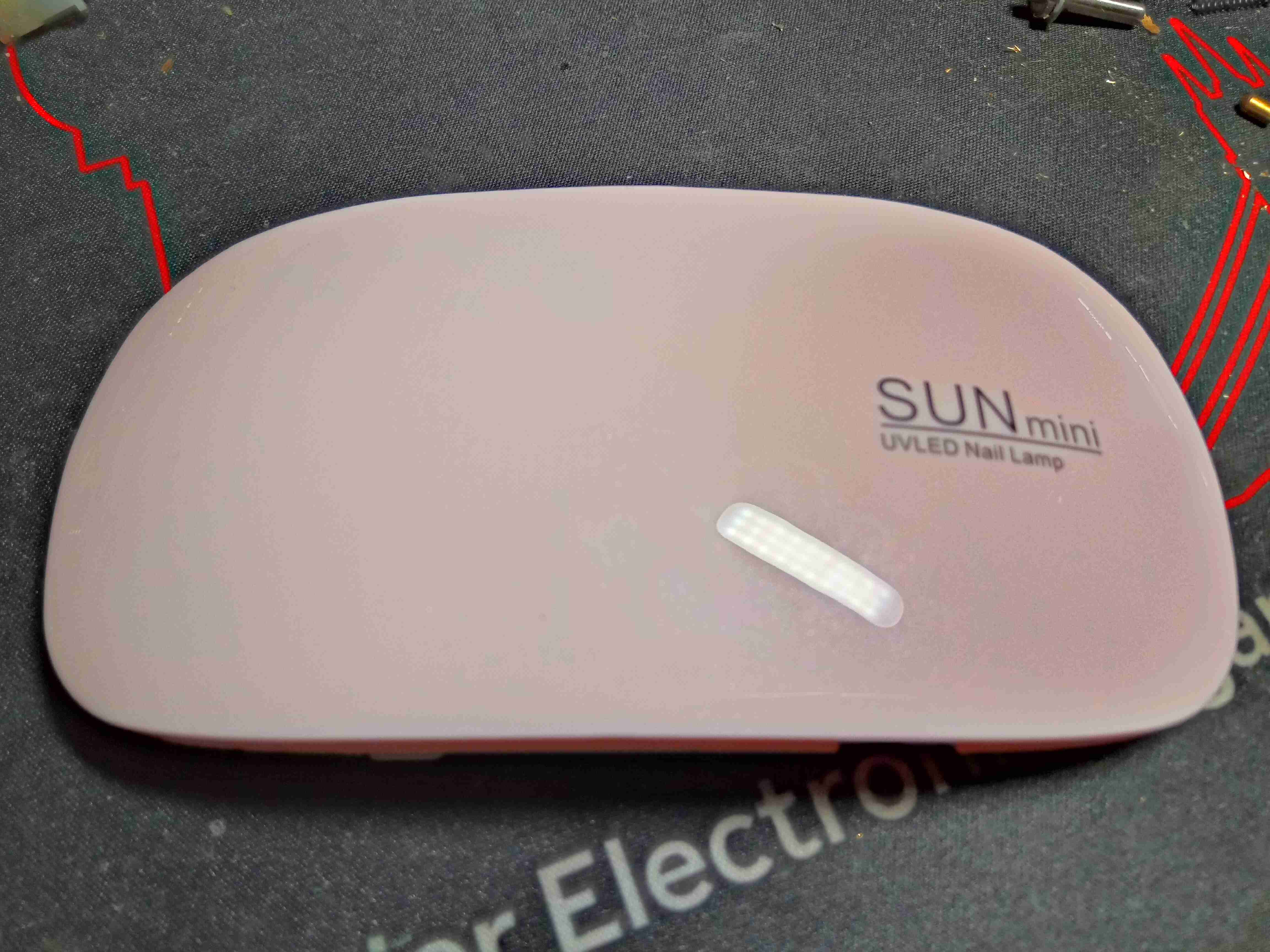
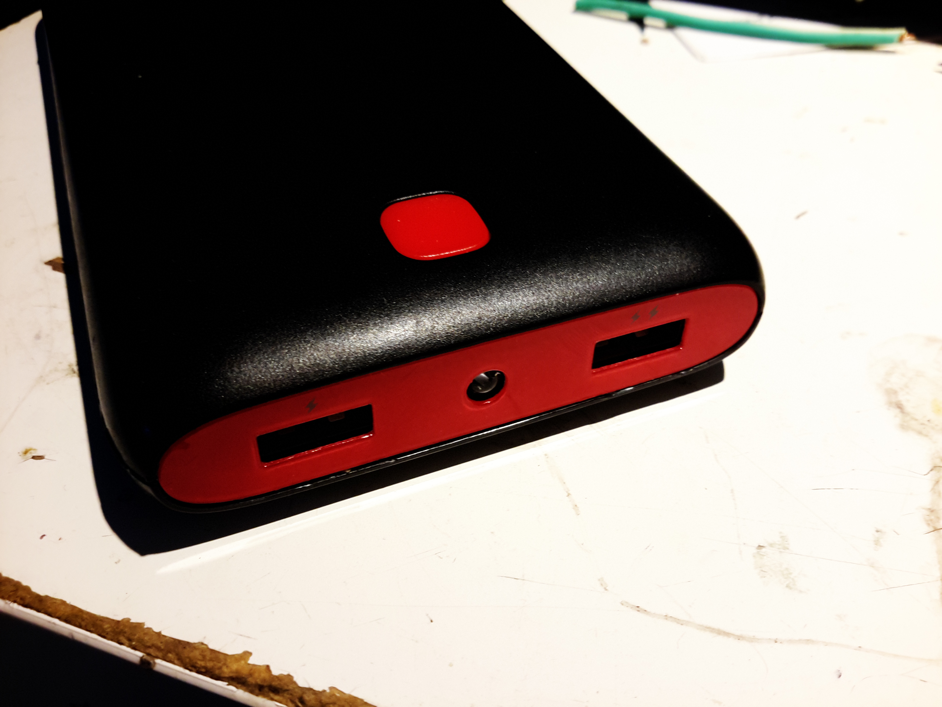
Time for another eBay delight! This is a little UV lamp for curing false nail glues. These are definitely taking over from the older Fluoroescent tube based units, and seem to work well enough. In my case, they work well for exposing UV-sensitive PCB substrates for etching as well!
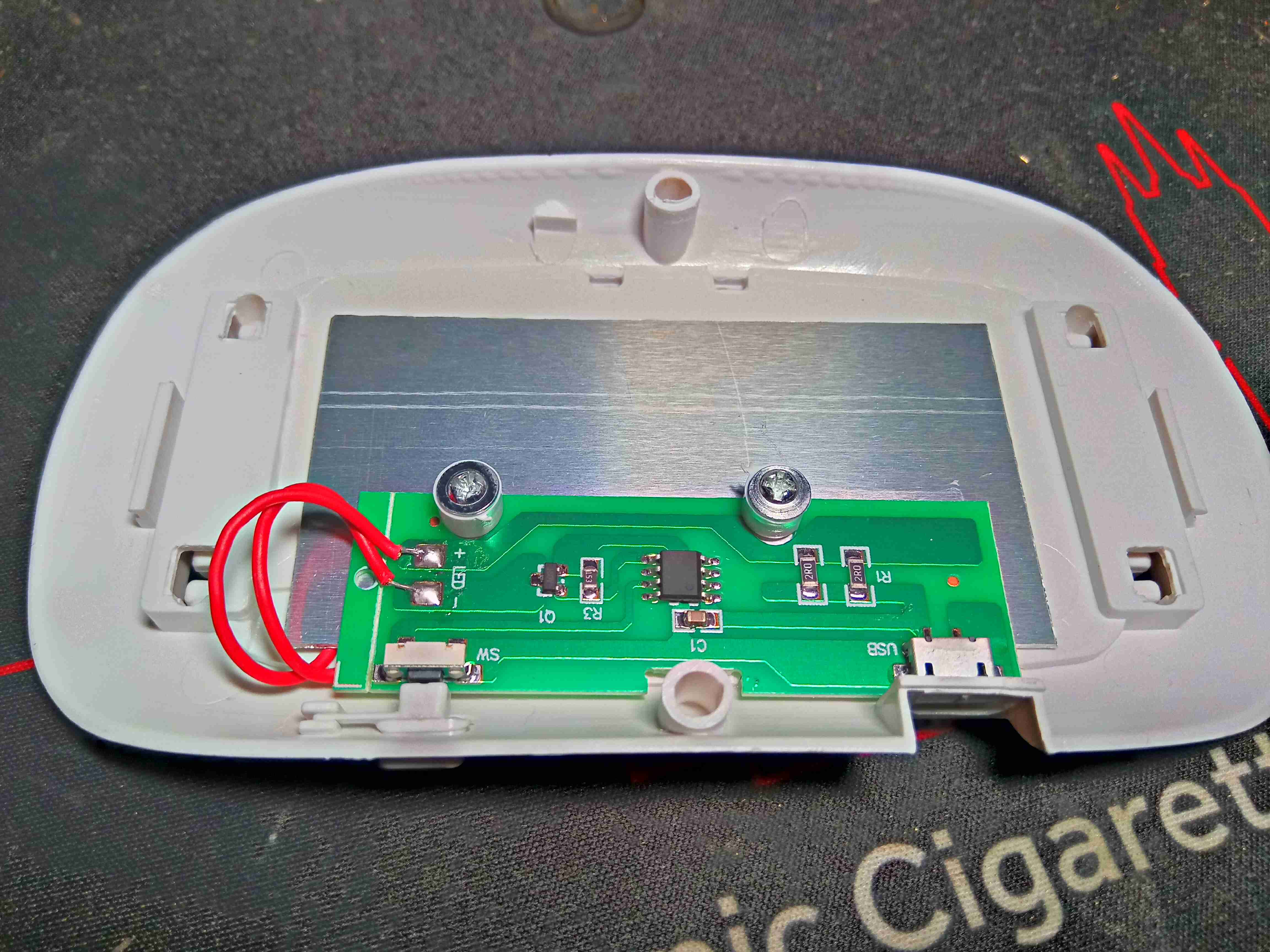
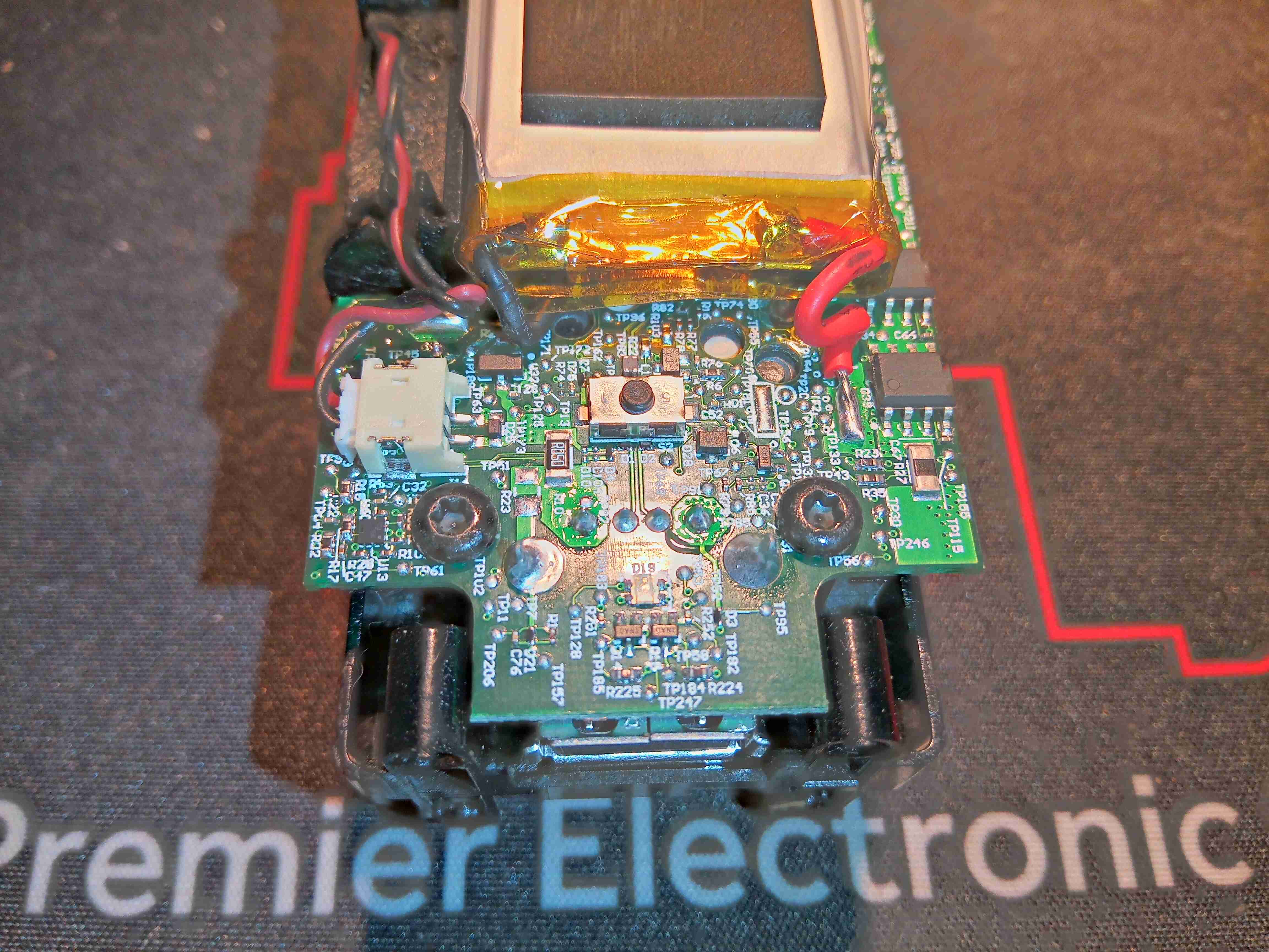
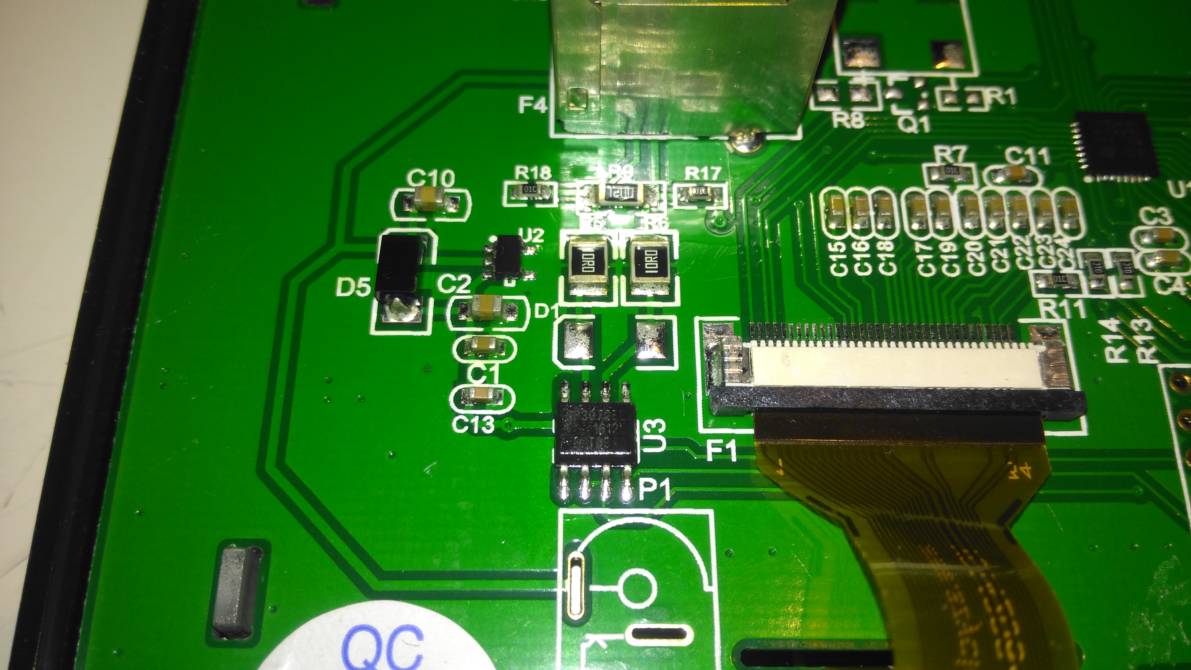
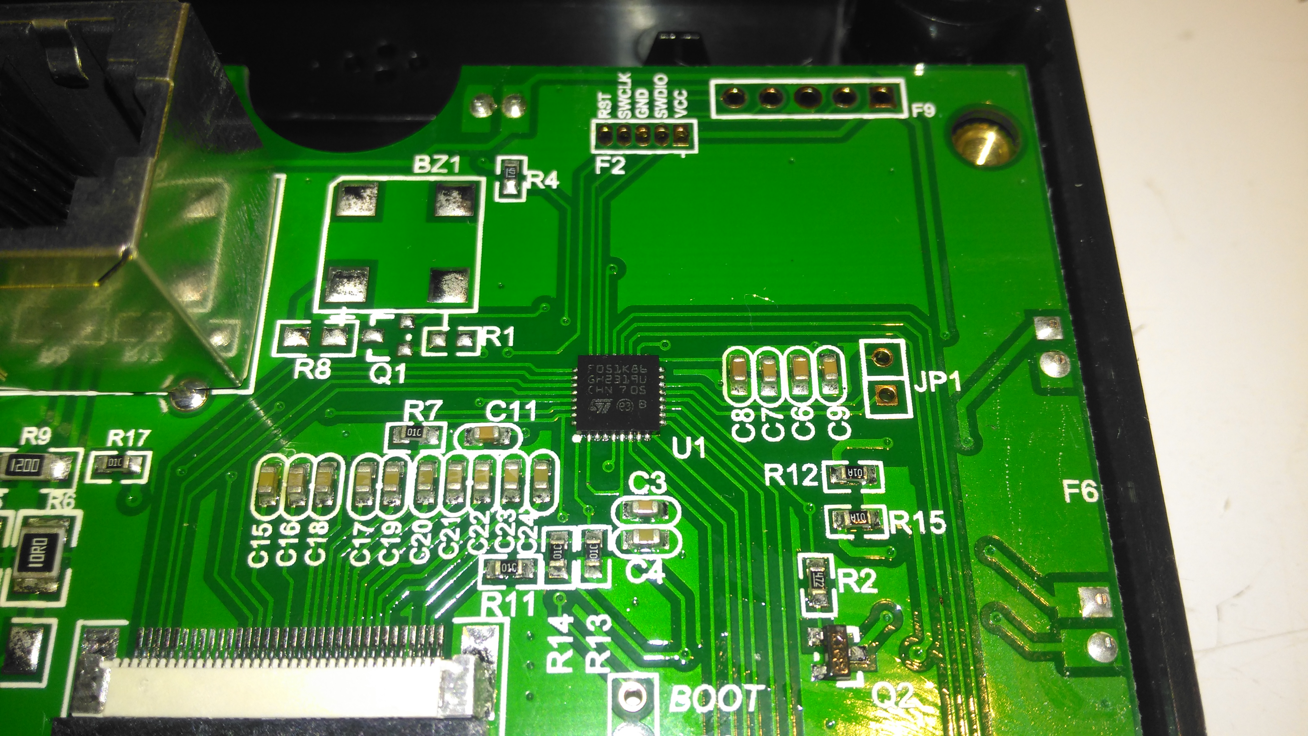
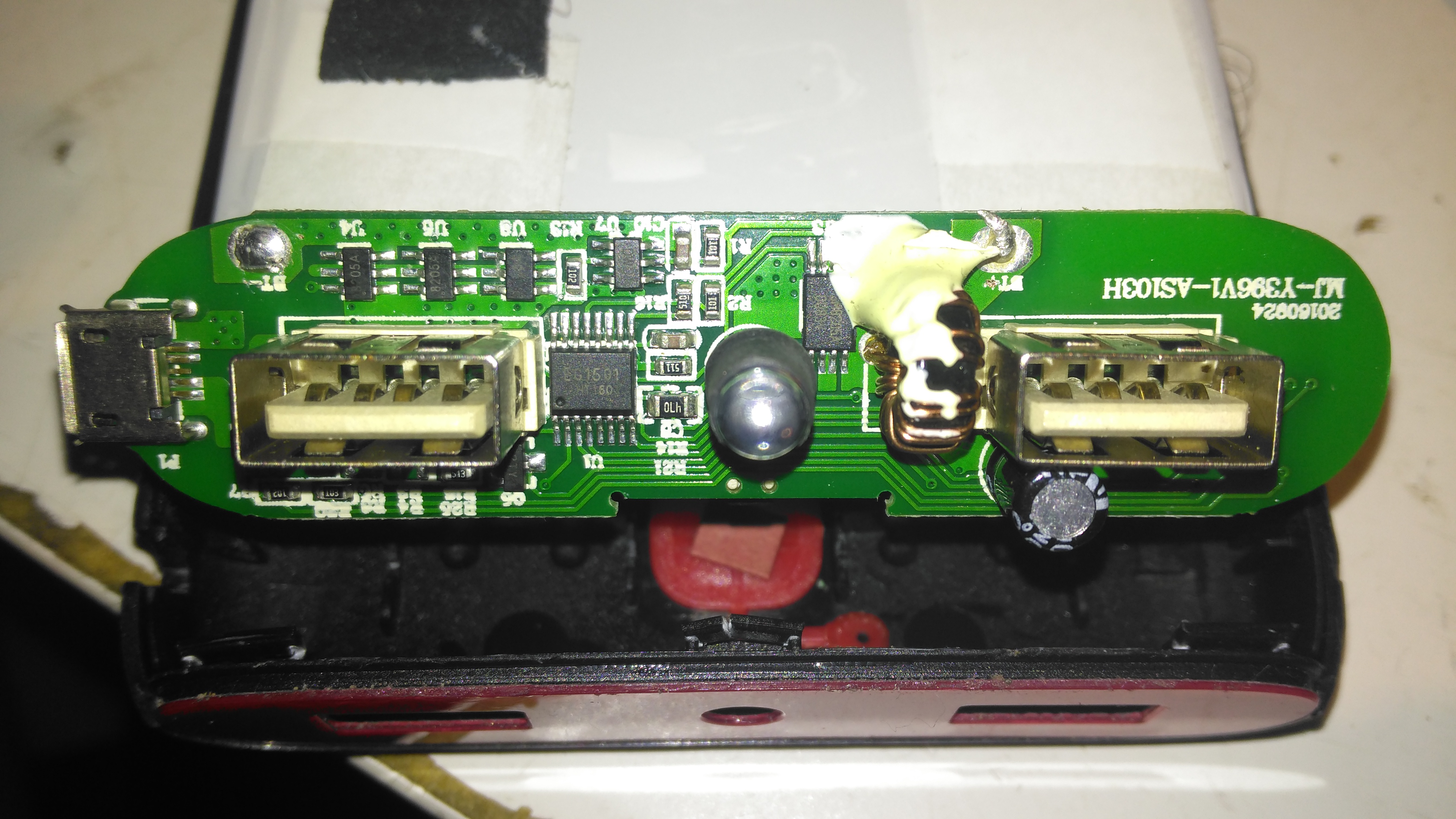
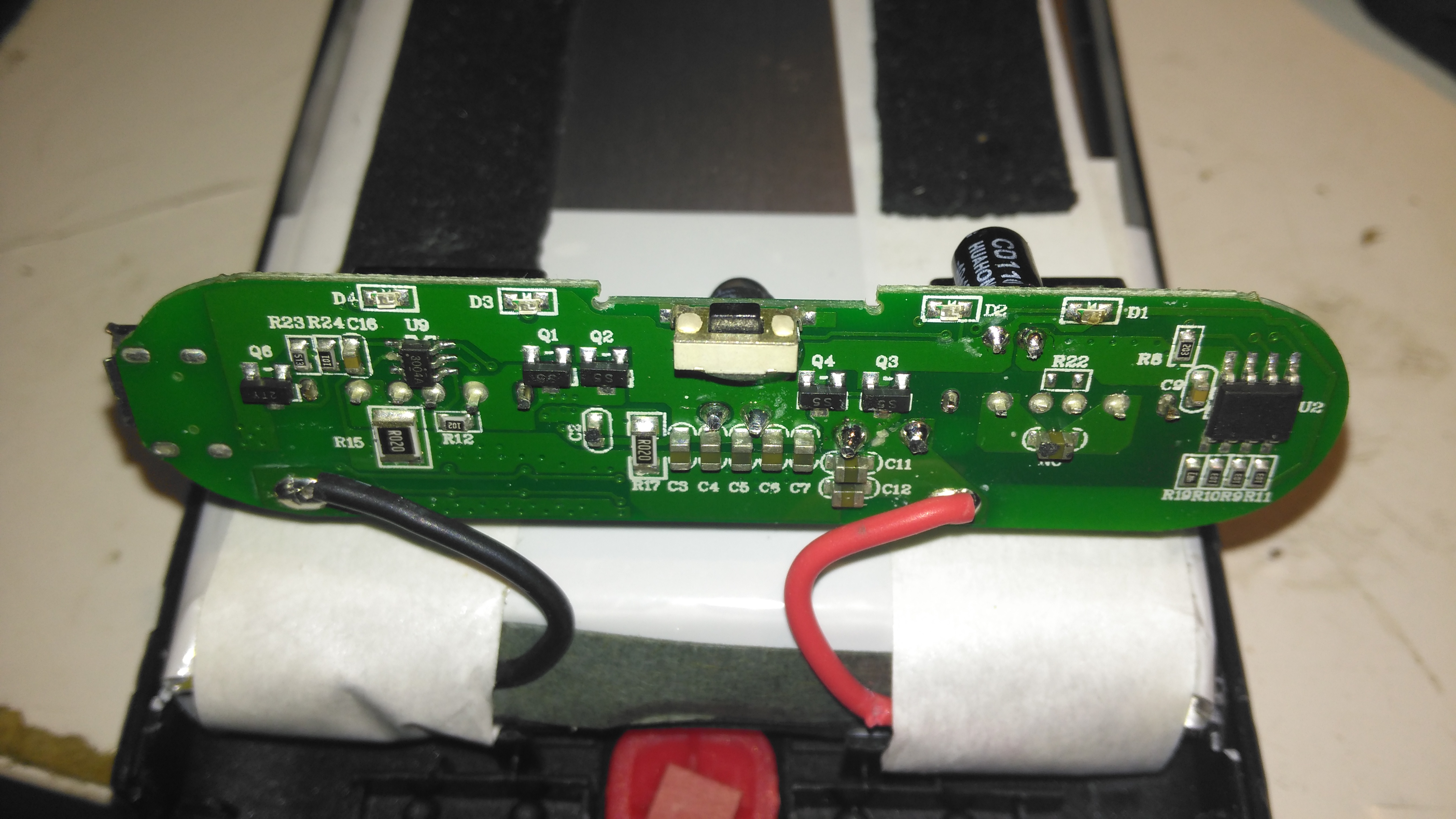
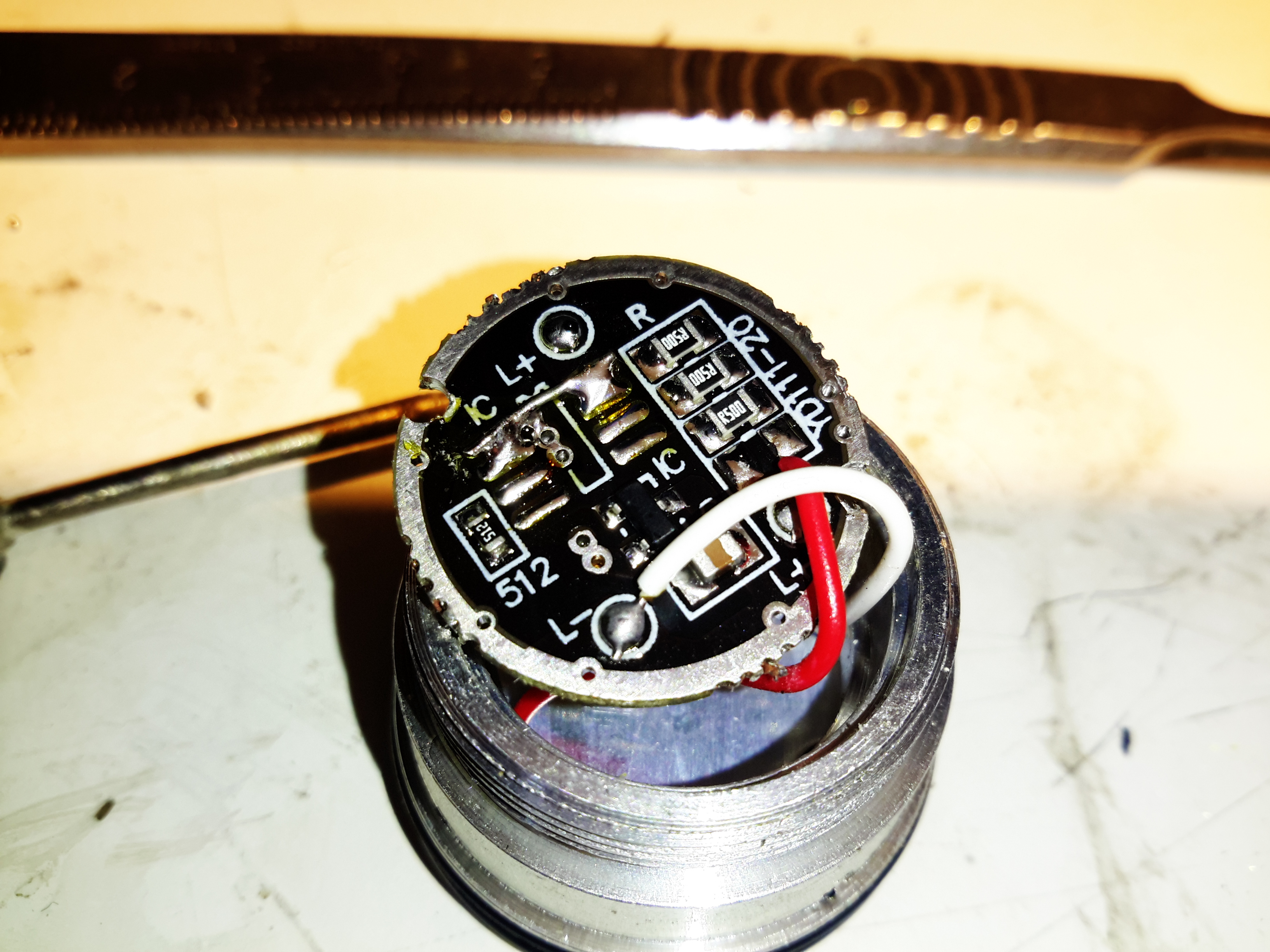
Here the cover has been unclipped from the body, no screws externally. There’s a small PCB, which holds an unmarked microcontroller, the USB input, the power & timer button, and a MOSFET for switching the LED current. A pair of 2Ω resistors in parallel on the right limit current through the LED array, in this case to 1.25A for an output power of 1.56W.
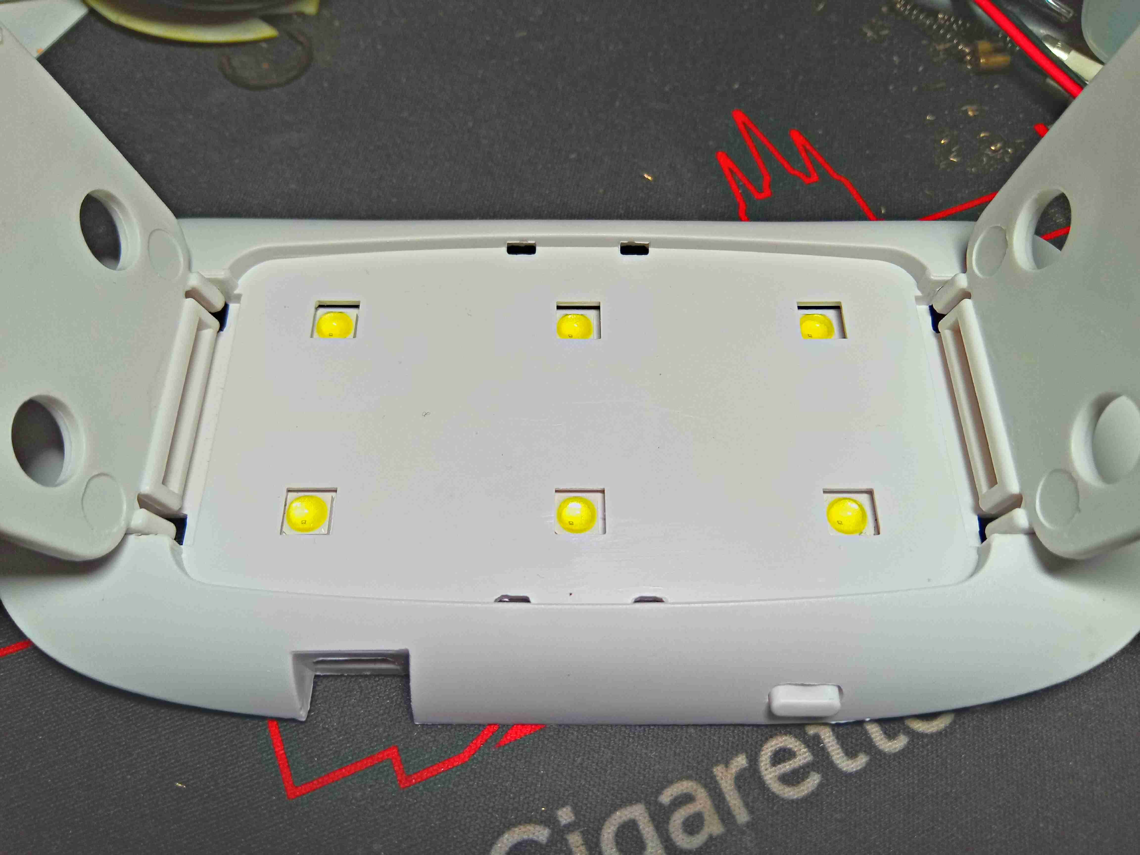
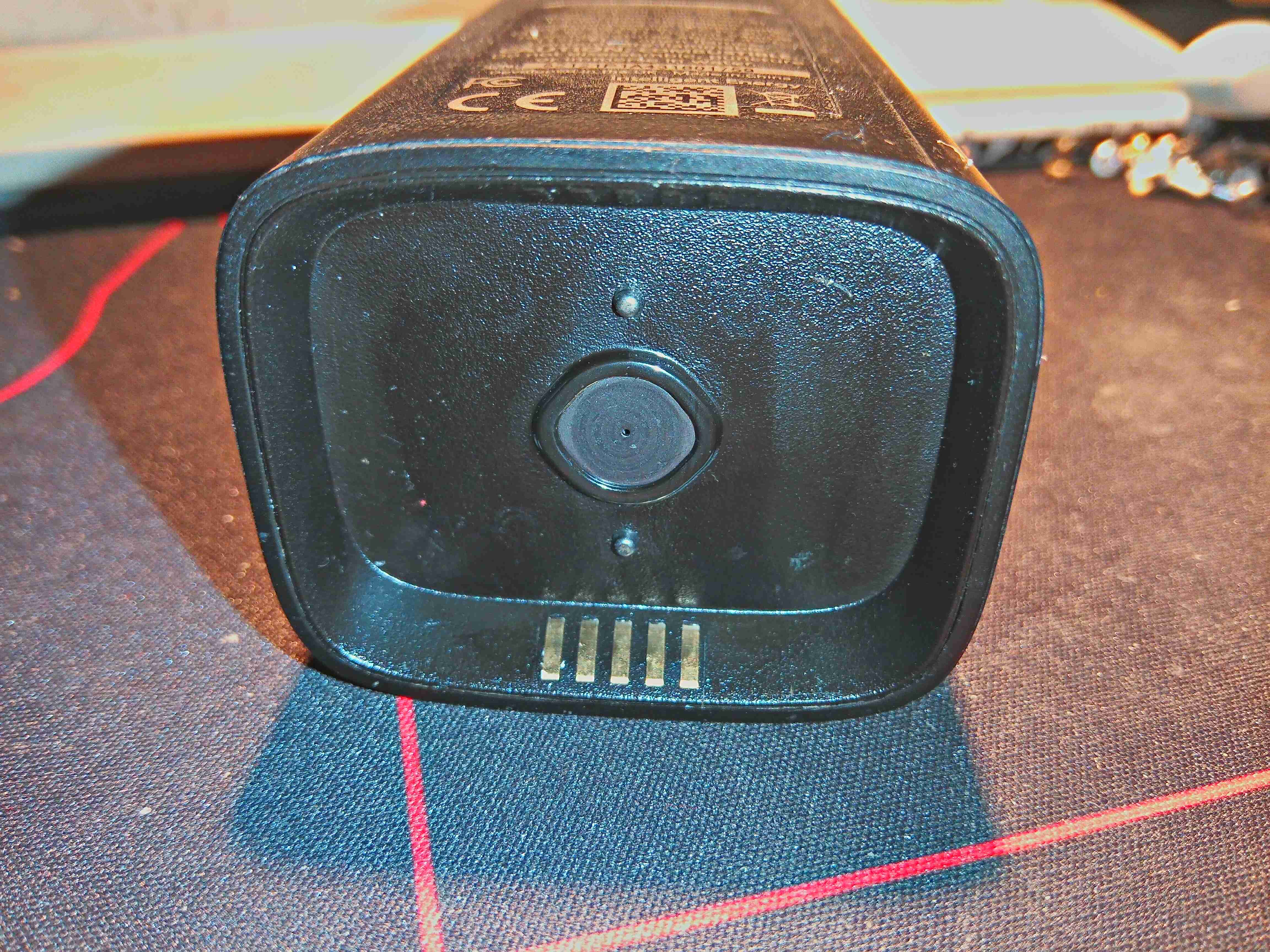
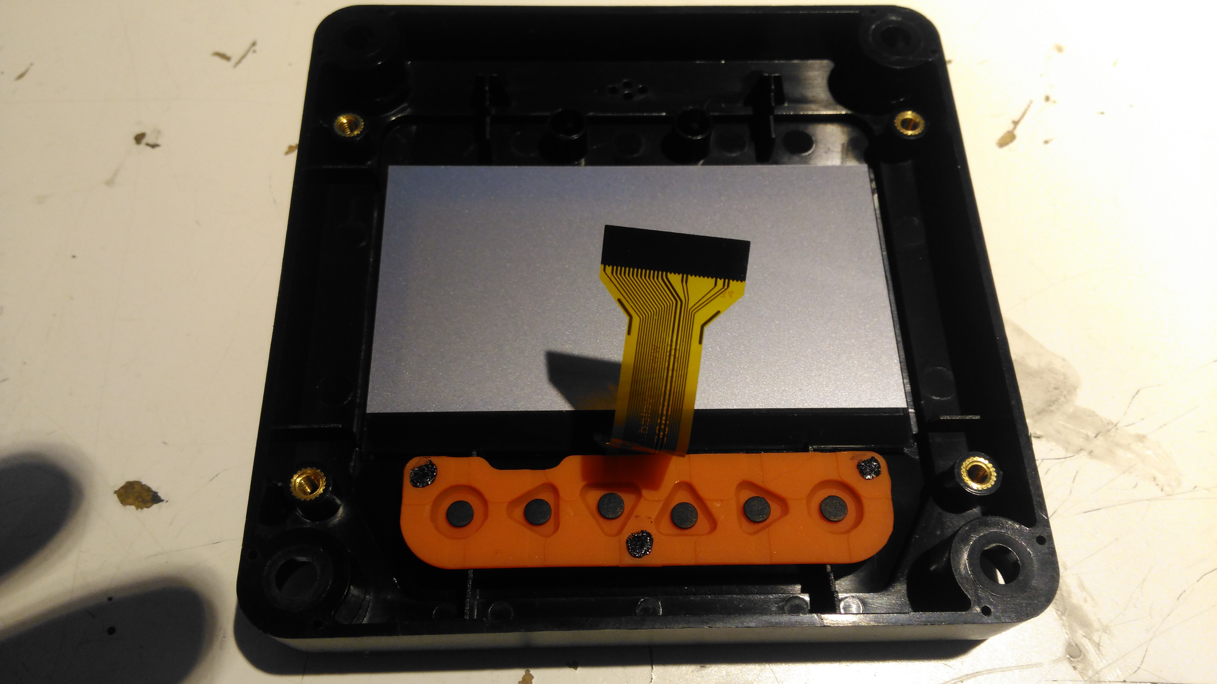
Lamp Bottom
Underneath the body are the apertures for the high-power UV LEDs. In this case there are 6 LEDs, each with a pair of dies of differing wavelengths. The legs fold up for storage.
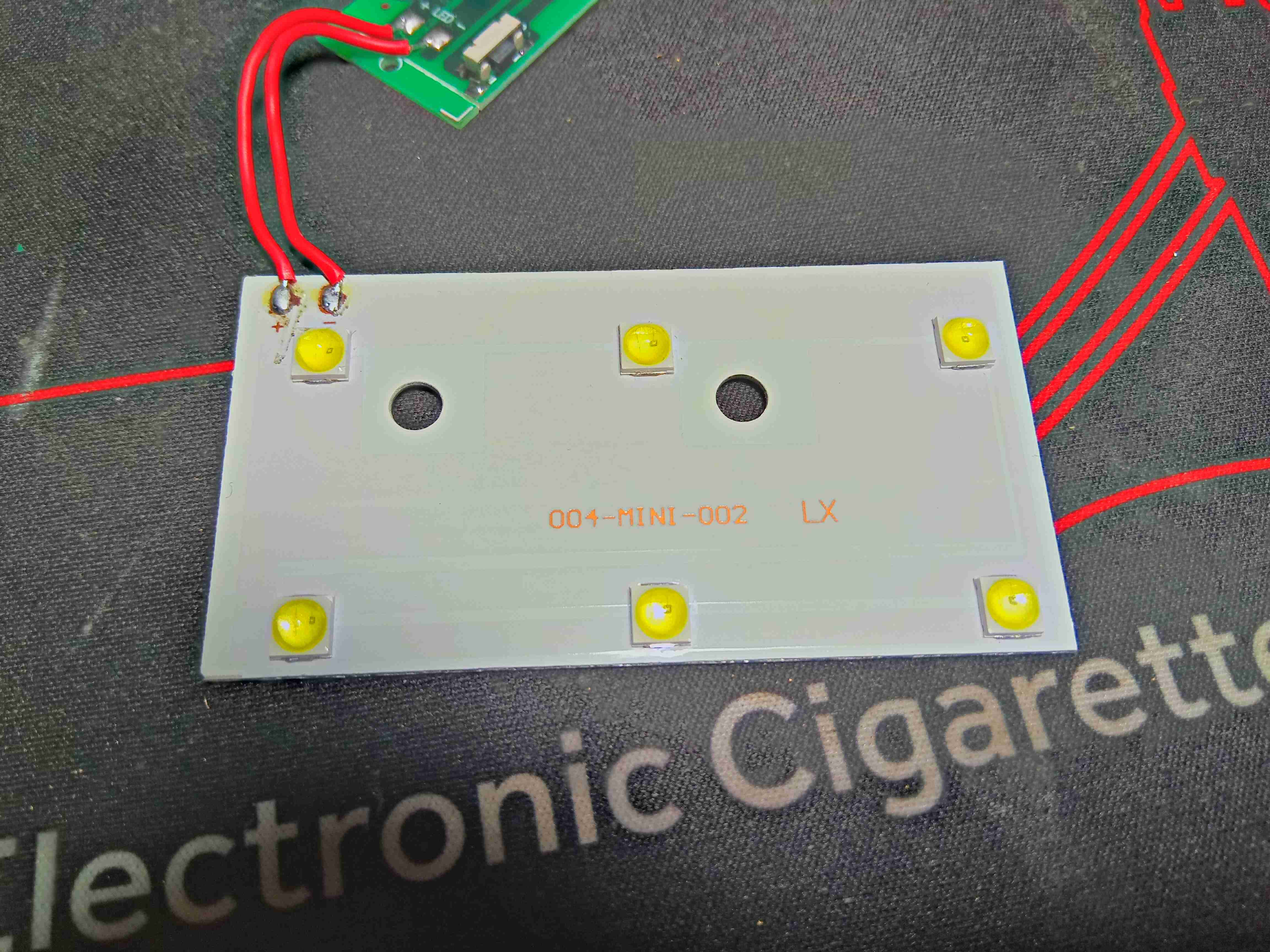
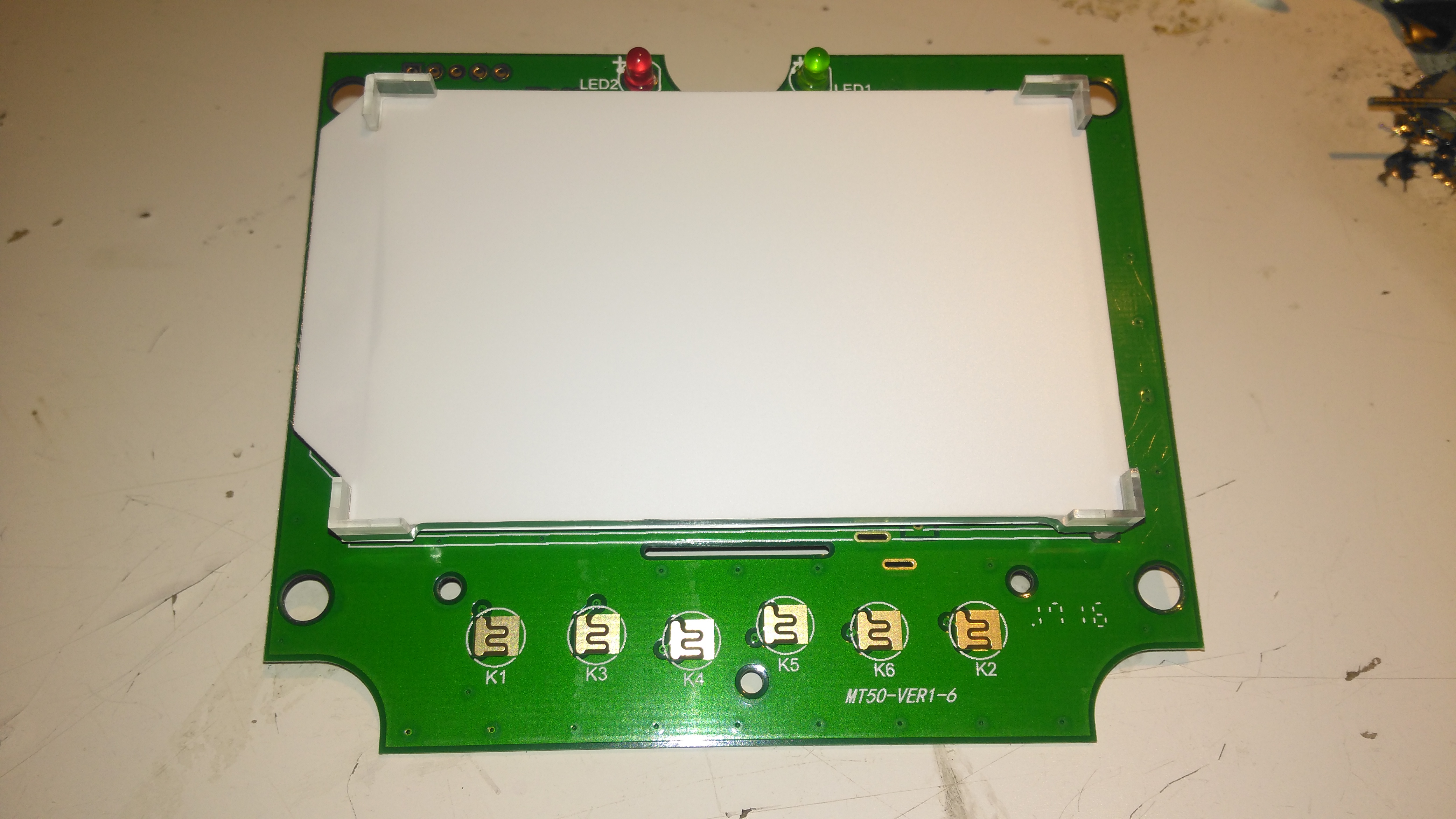
LED PCB
Removing the 2 screws inside allows the boards to come loose, and this is the front of the aluminium-cored PCB supporting the LEDs. In this case they are all wired in parallel.
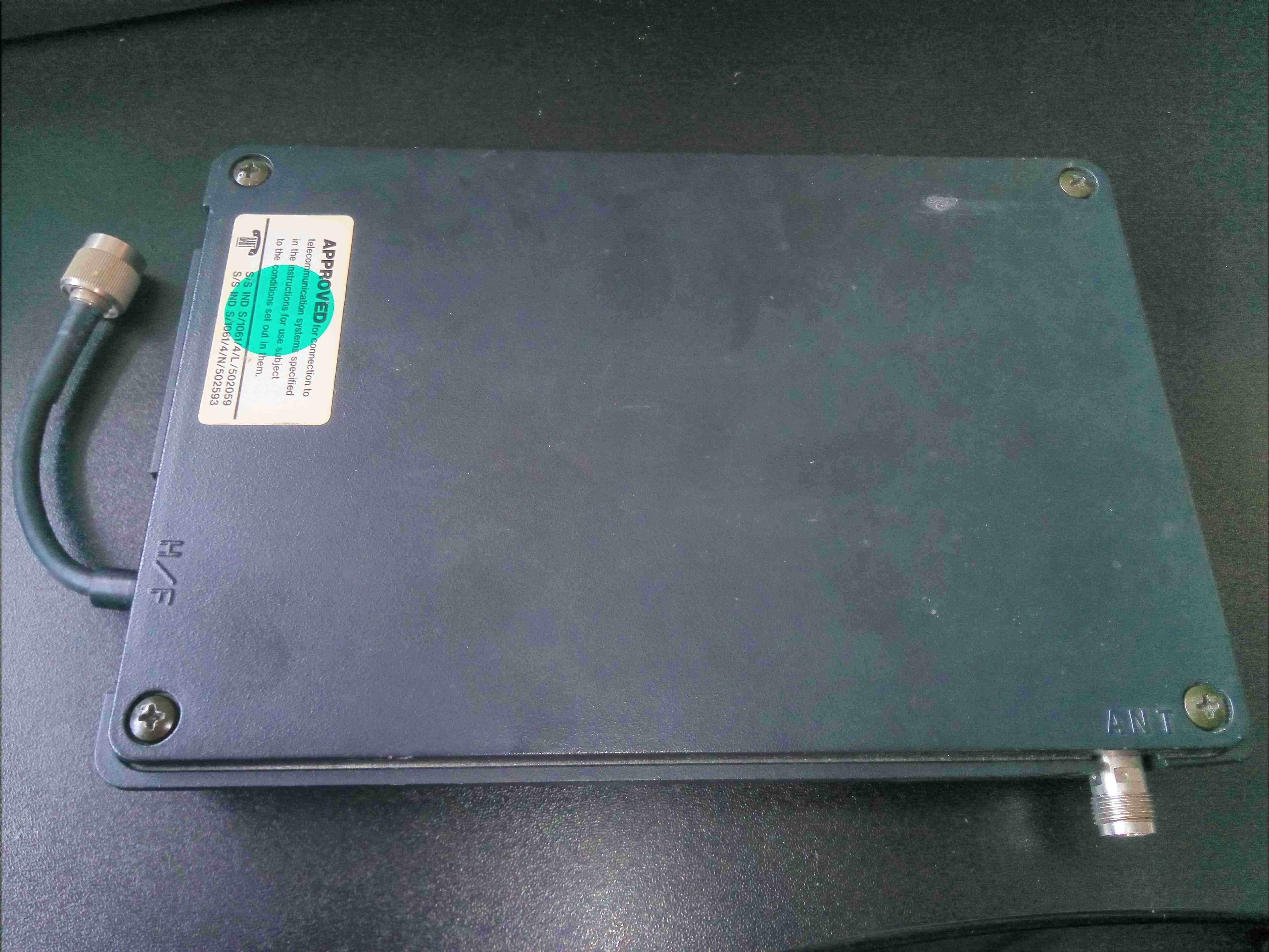
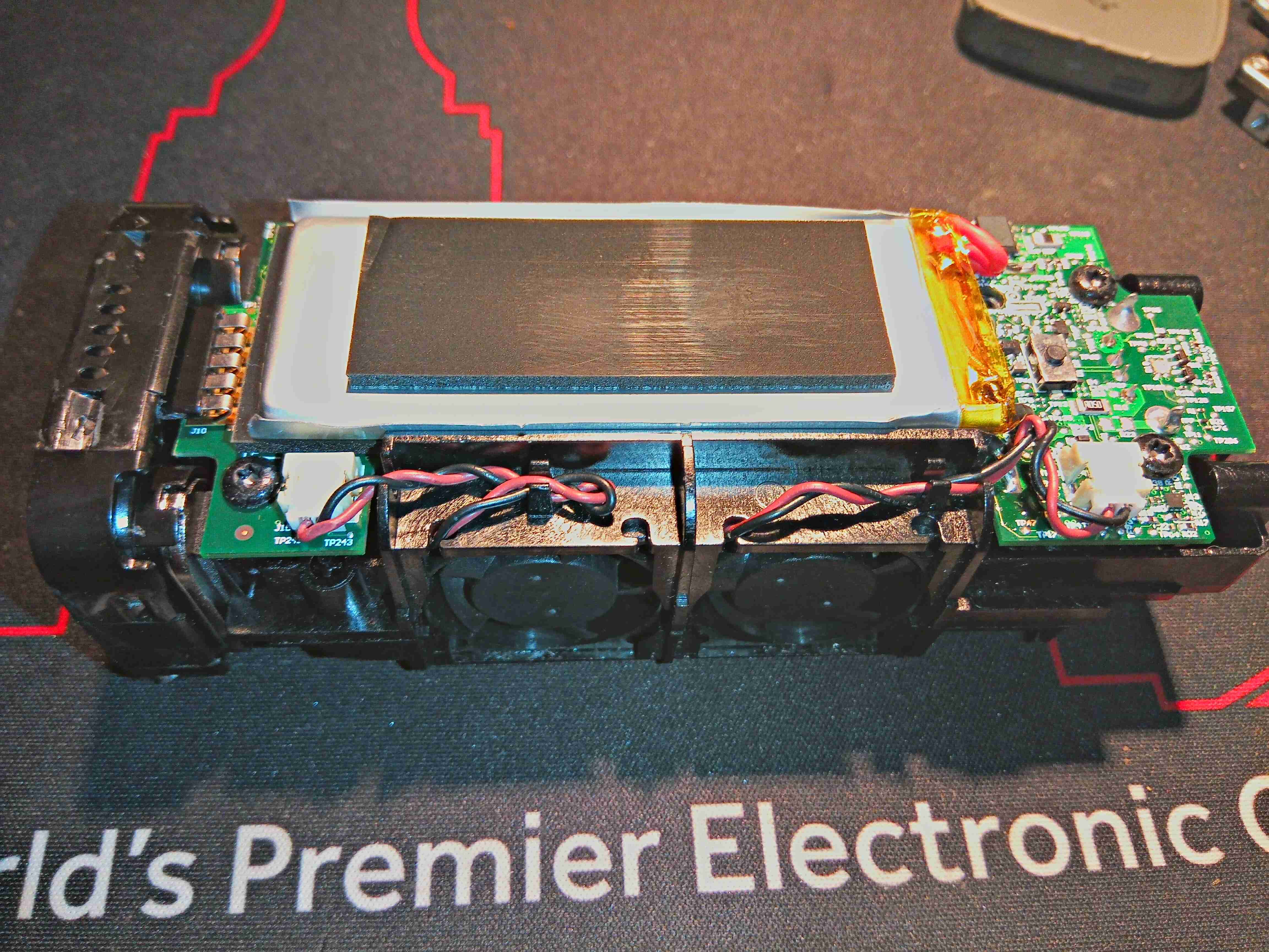
Here’s a blast from the past, before the time of GSM networks. This is a power amplifier from an Analogue mobile phone, on the ETACS system. This unit will output, according to the TACS standard, about 10W of RF power in the 900MHz band. RF connections on this unit are made via TNC connections, and a DIN connector for power & control. This unit is made of solid aluminium, no plastic casing here! The metal is needed for both RF shielding, and heatsinking capability for the power amplifier module inside.
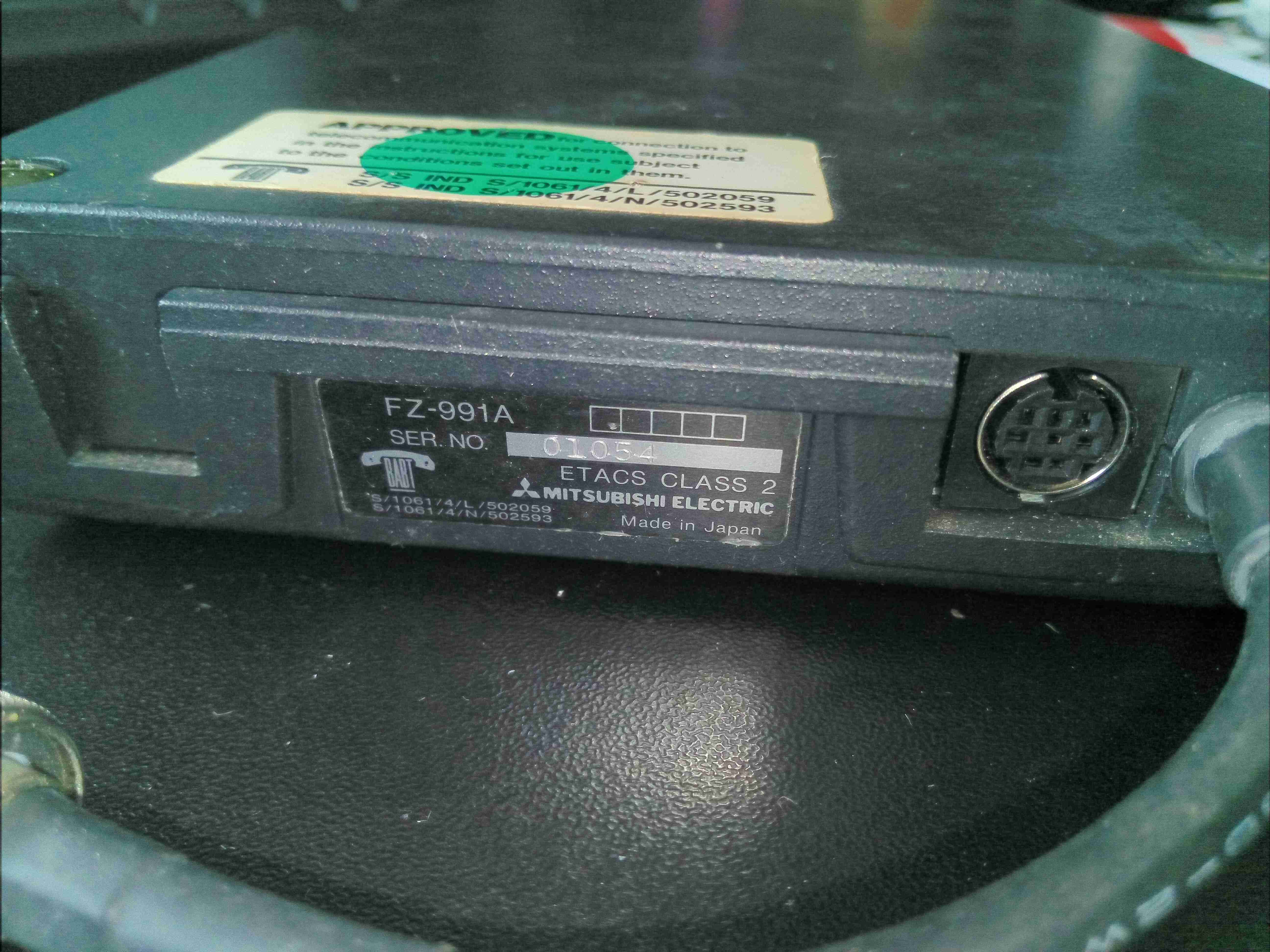
Rating Label & Control
Here’s the rating label, and the control connector.
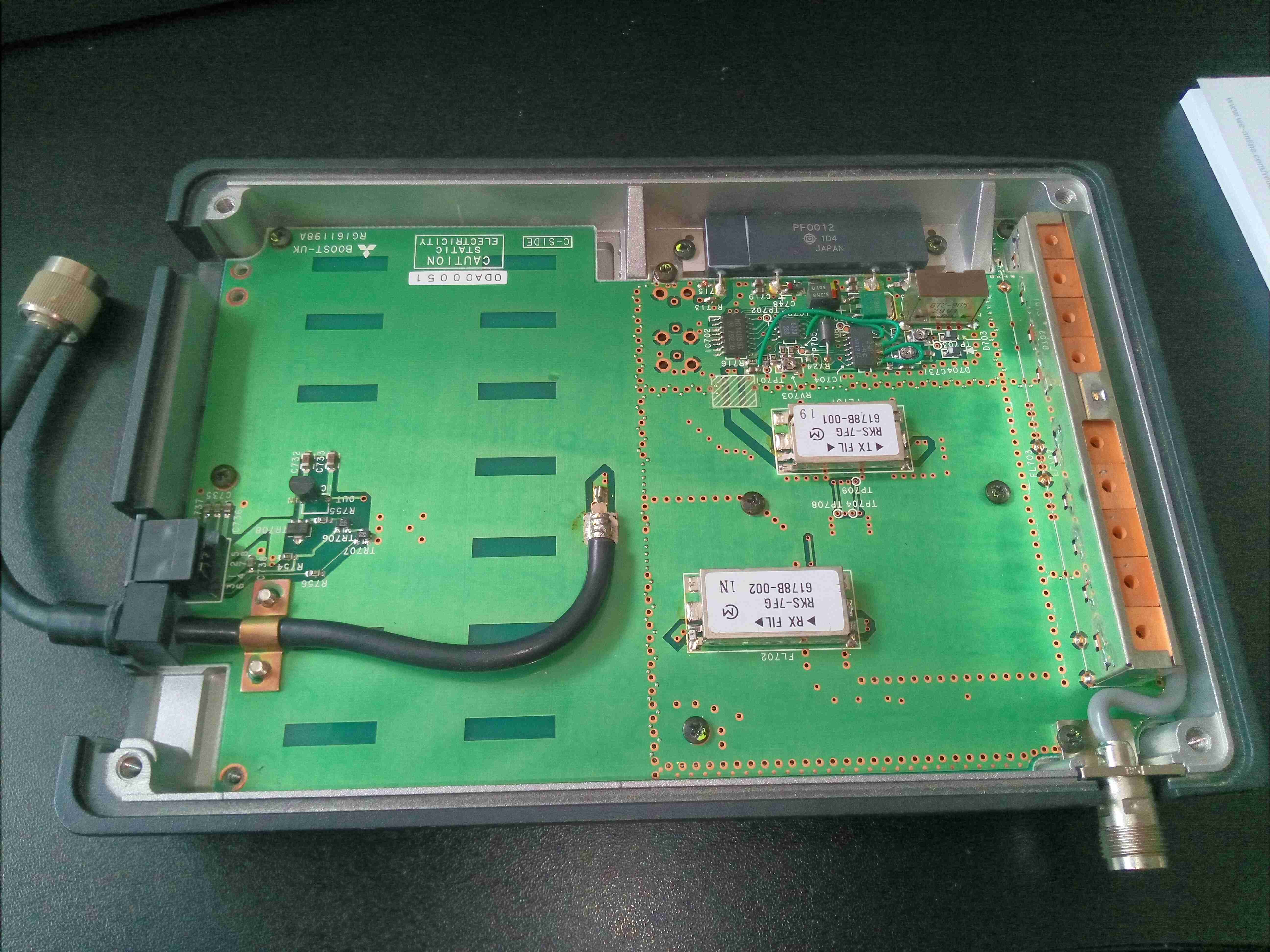
Cover Removed
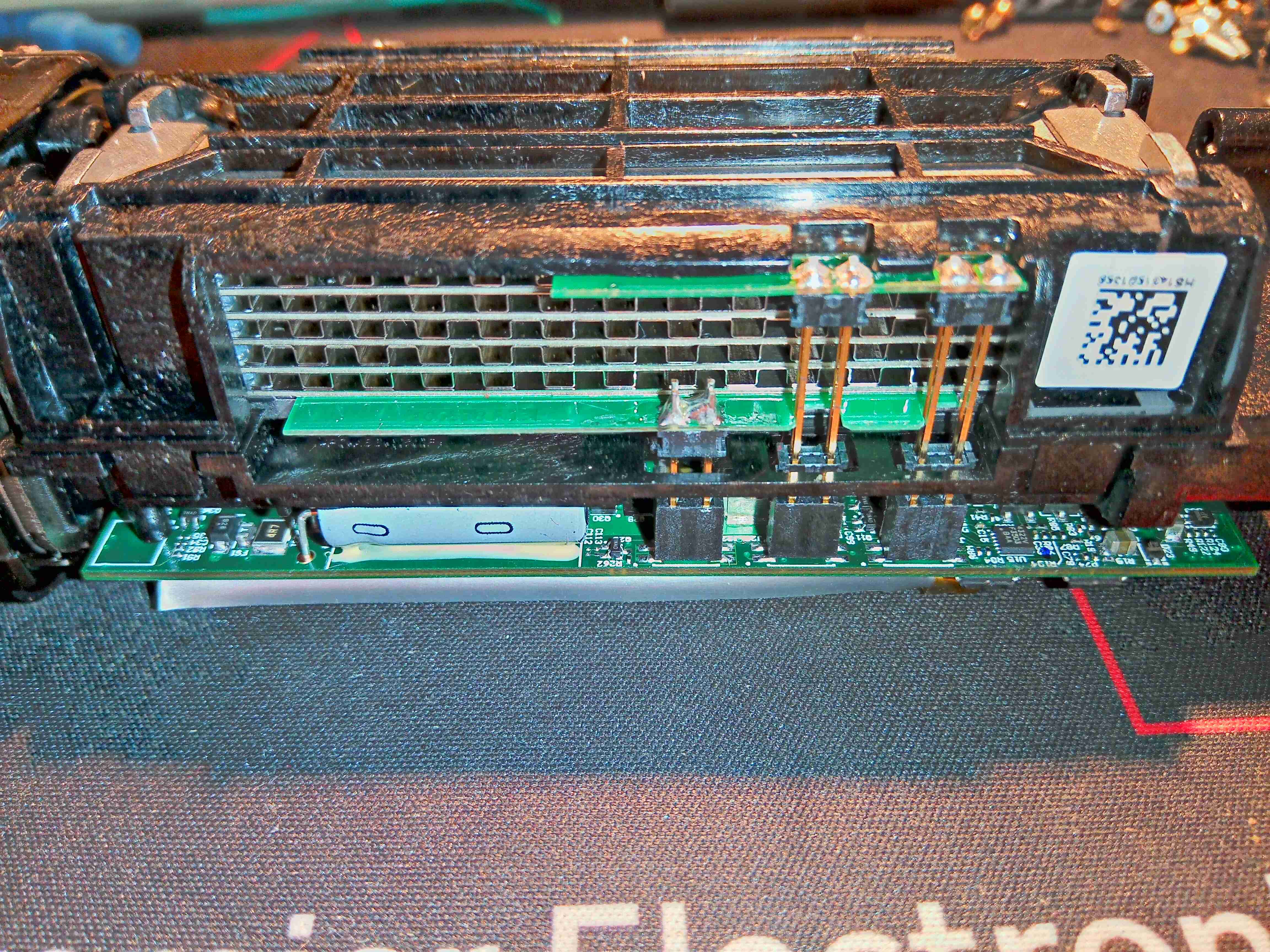
Removing 4 screws allows the lid to be removed from the cast base. There’s RF shielding gasket around the edge of the lid, along with the internal sections of the amplifier. The board is pretty sparsely populated. RF input is via the short cable on the left, and output to the antenna on the lower right.
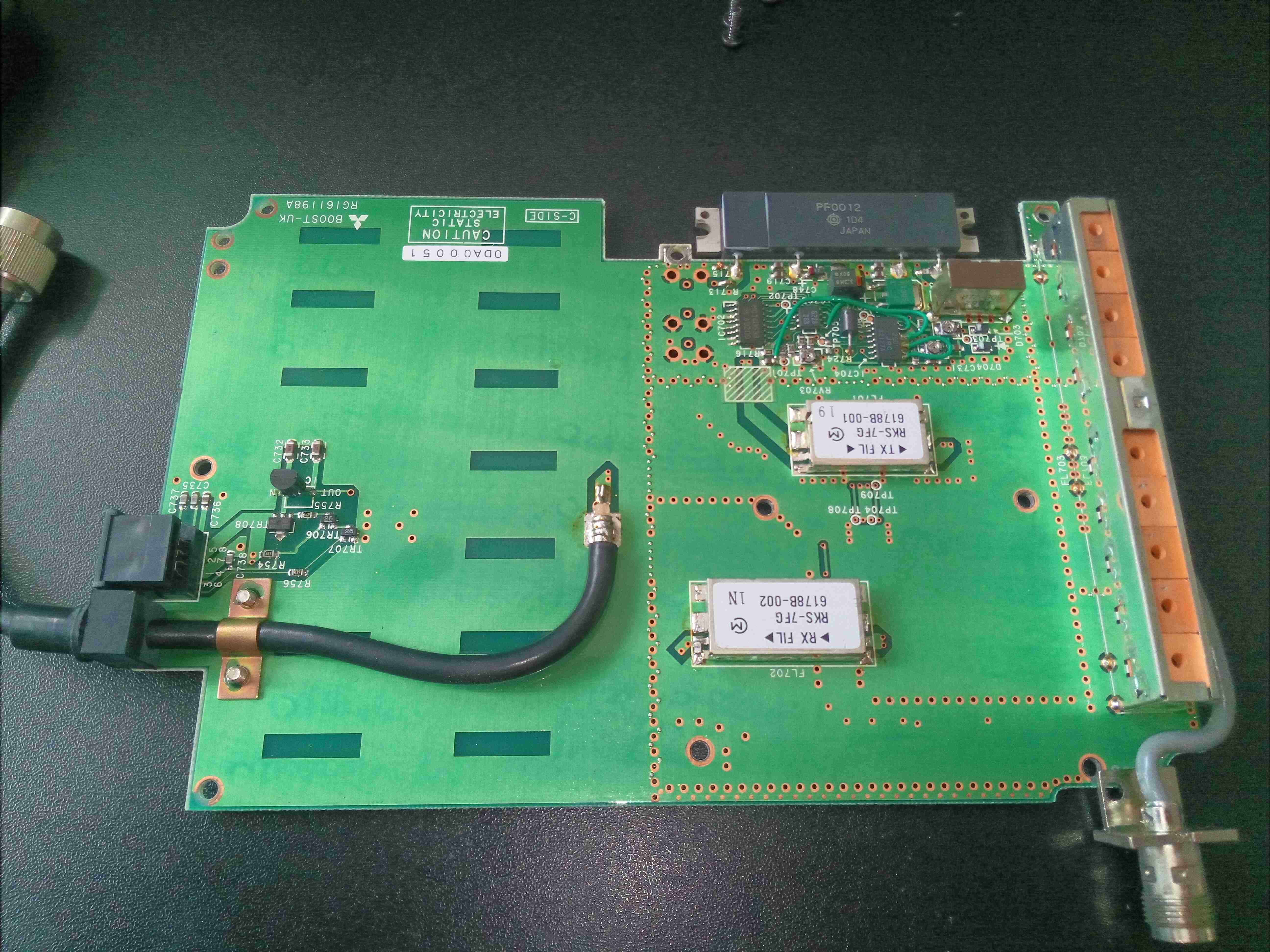
Bare PCB Top
A few more screws & the PCB comes out of the cast base.
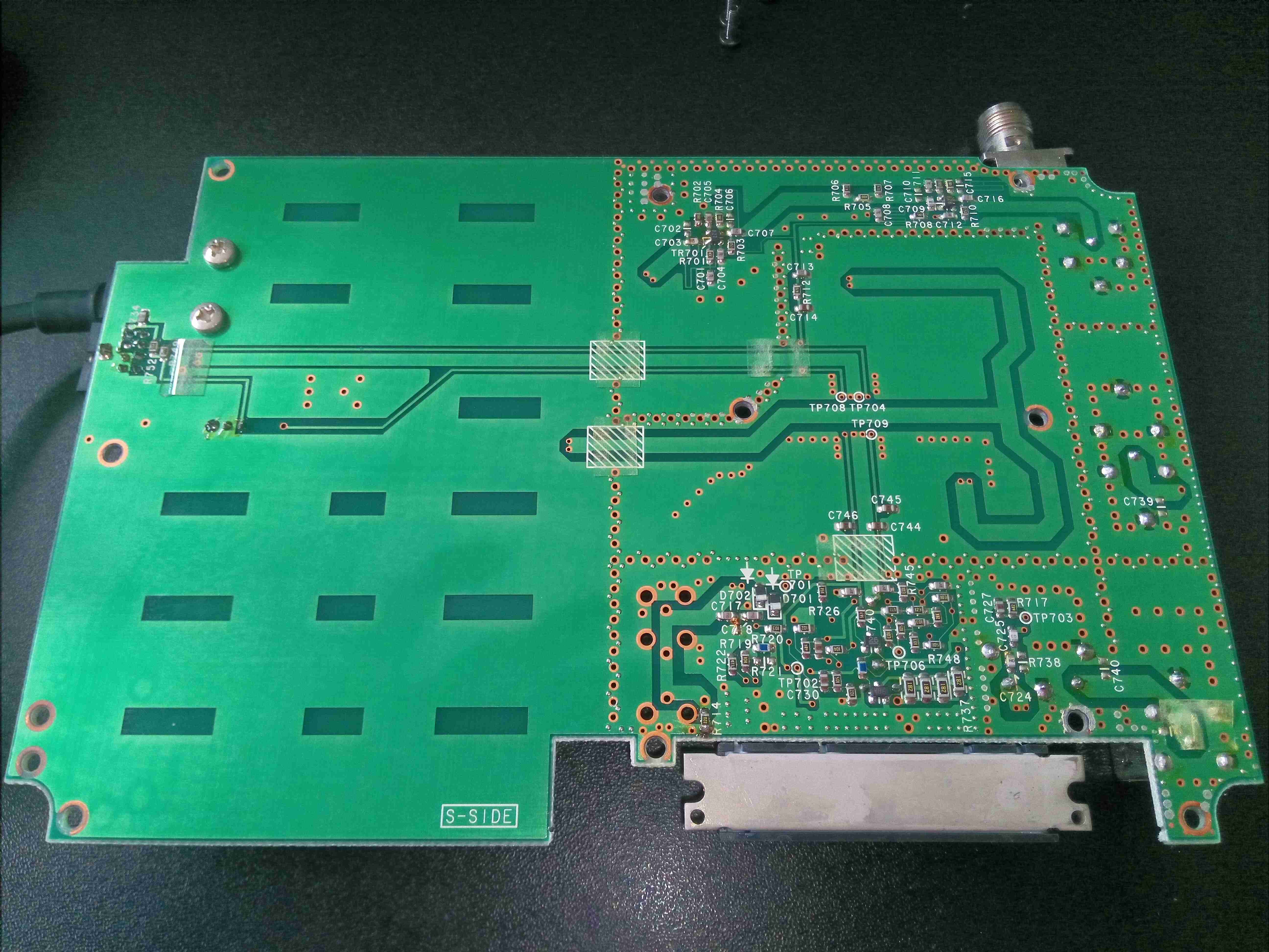
Bare PCB Bottom
Not much on the bottom of the board, apart from a lot of via stitching & passive components.
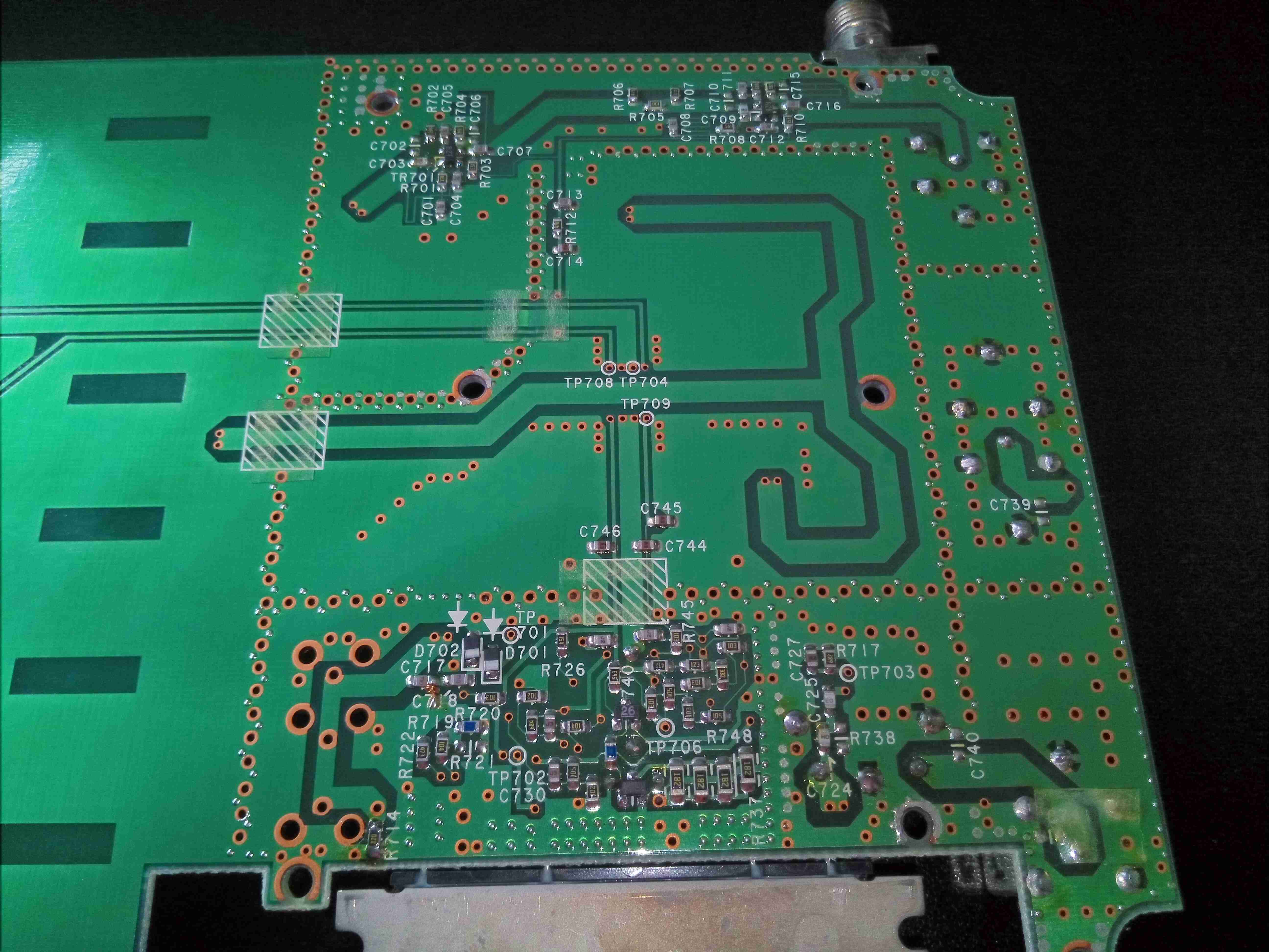
RF Section Tracks
Under the RF section is very dense with passives, and via stitching to separate the sections.
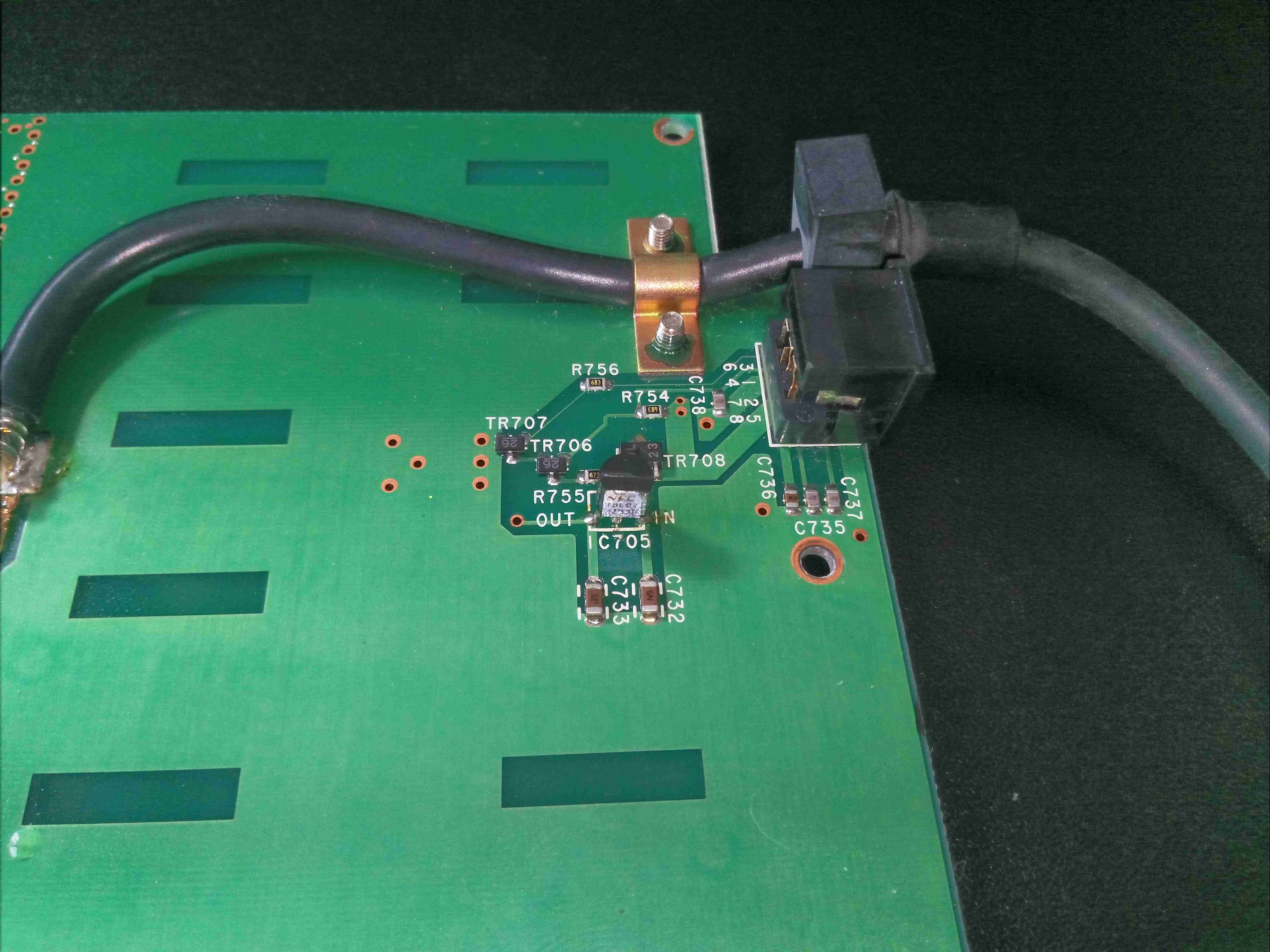
Voltage Regulator
There’s a 7v linear regulator near the power input connection, most likely to provide a biasing supply for the RF power section.
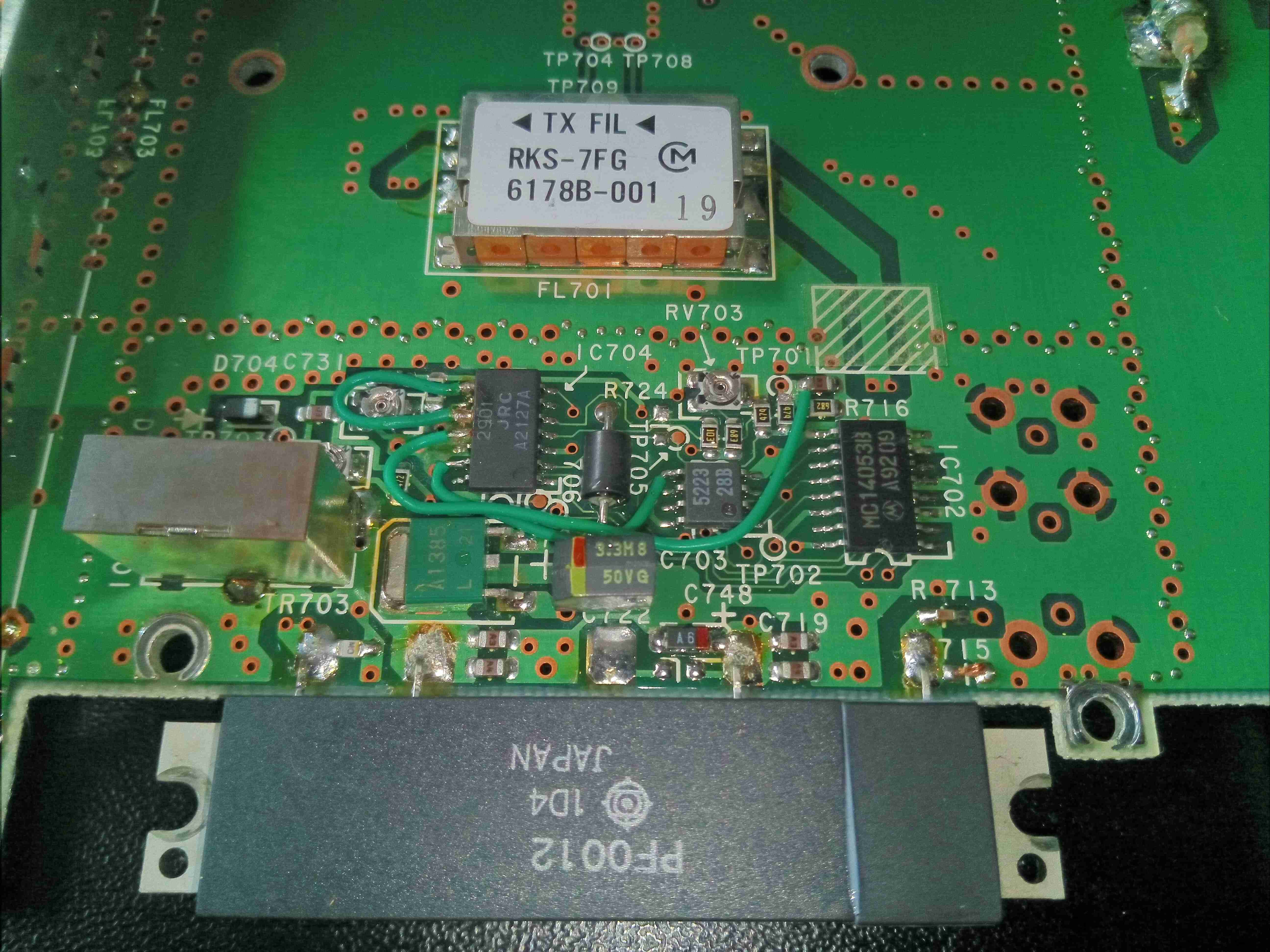
Amplifier Section
The main power amplifier is a Hitachi PF0012 module, these were very common in radios, and contain all the components required for an RF PA stage. I couldn’t find a specific datasheet for this module unfortunately. There are some support components inclusing a NMJ2901 Quad comparator from JRC, and a MC14051B Analogue Mux/Demux.
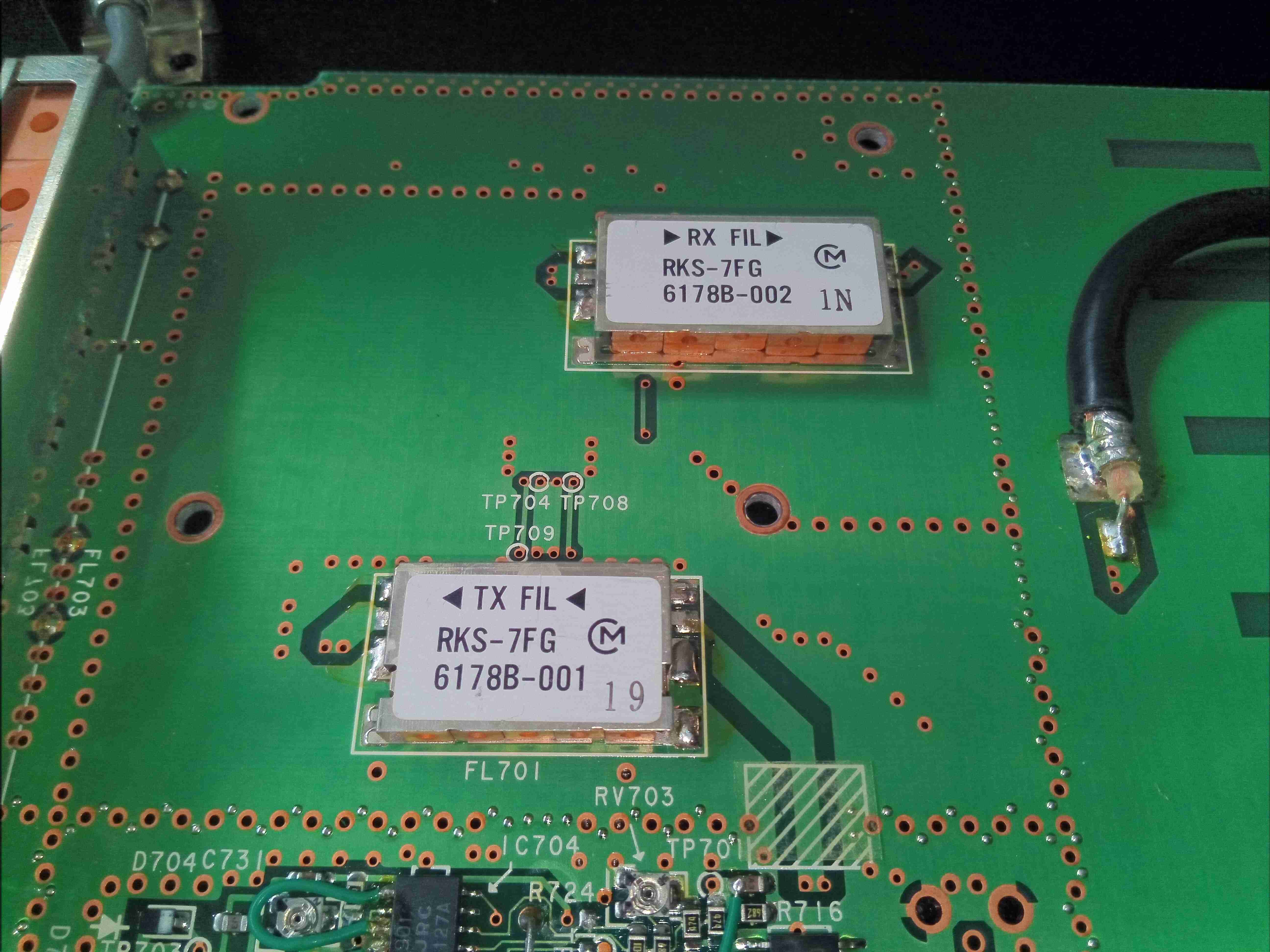
Duplexing Filters
Filtering of the TX & RX frequencies is done by this pair of units from MuRata
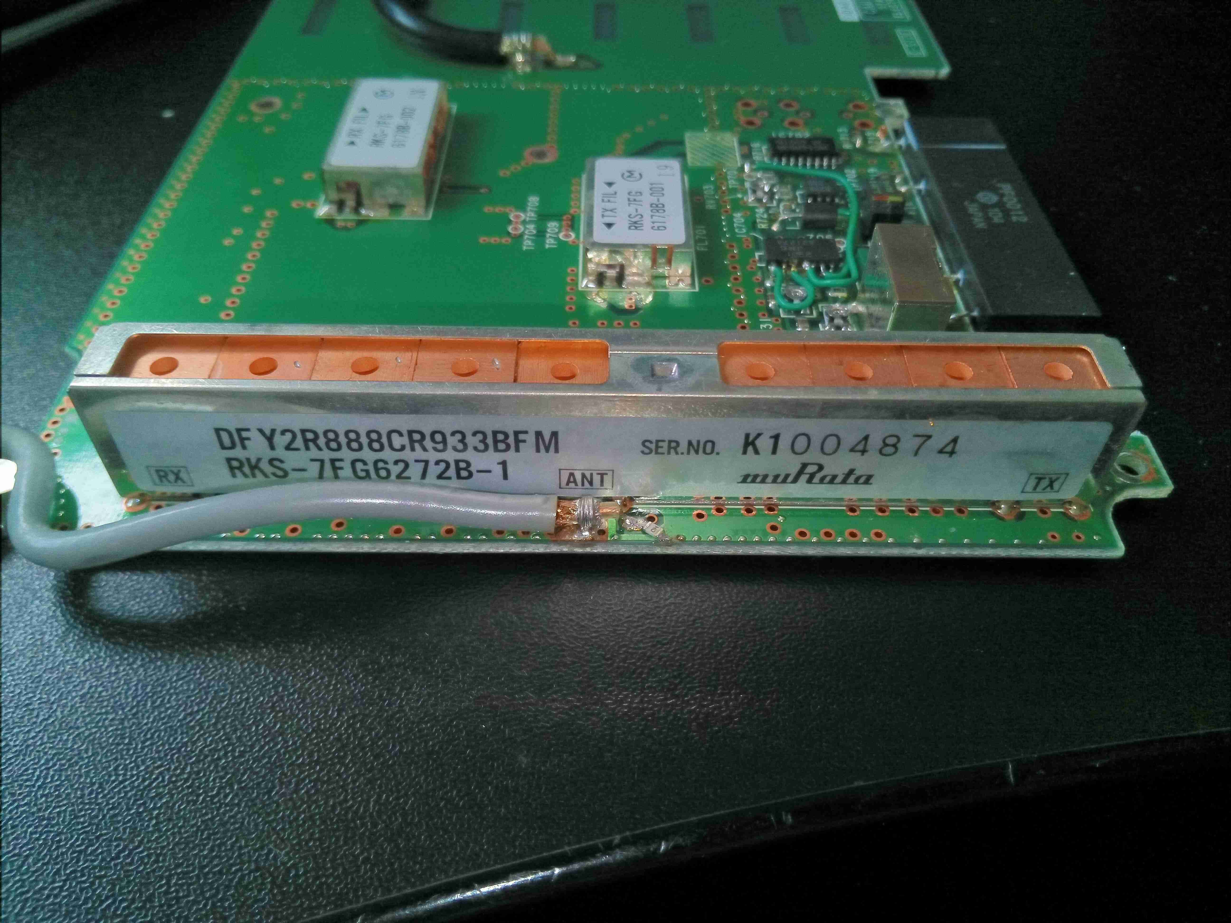
Antenna Duplexer
Finally, there’s an antenna duplexer on the output side, also from MuRata. Unfortunately no datasheets available for any of these parts.
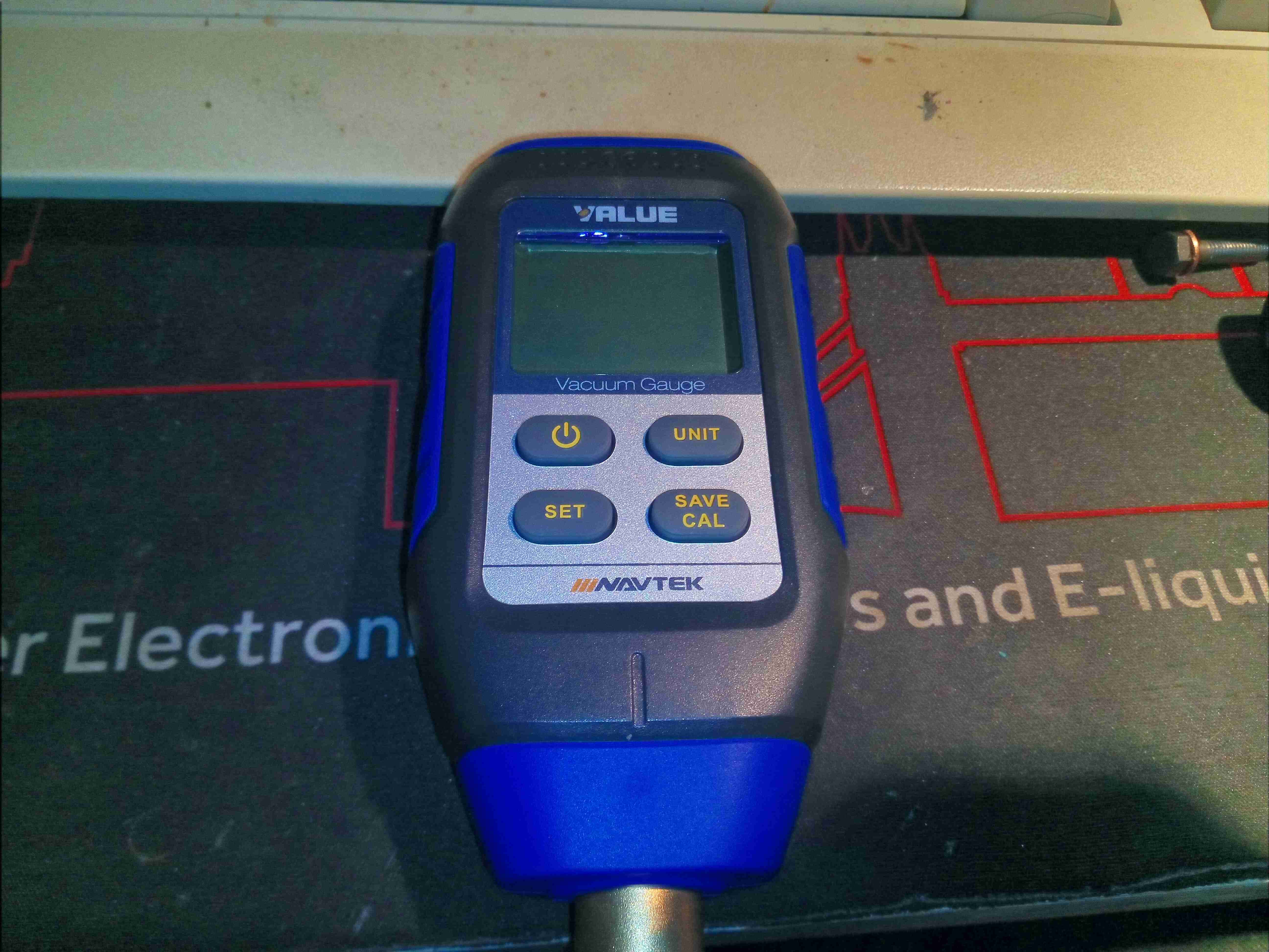
Time for another tool teardown! Here’s a VMV-1 Vacuum gauge, for refrigeration system service use. This unit will measure in Pa, millibar, mmHg & InHg, displaying it’s reading on a nice backlit LCD. Power is provided by a trio of AA cells.
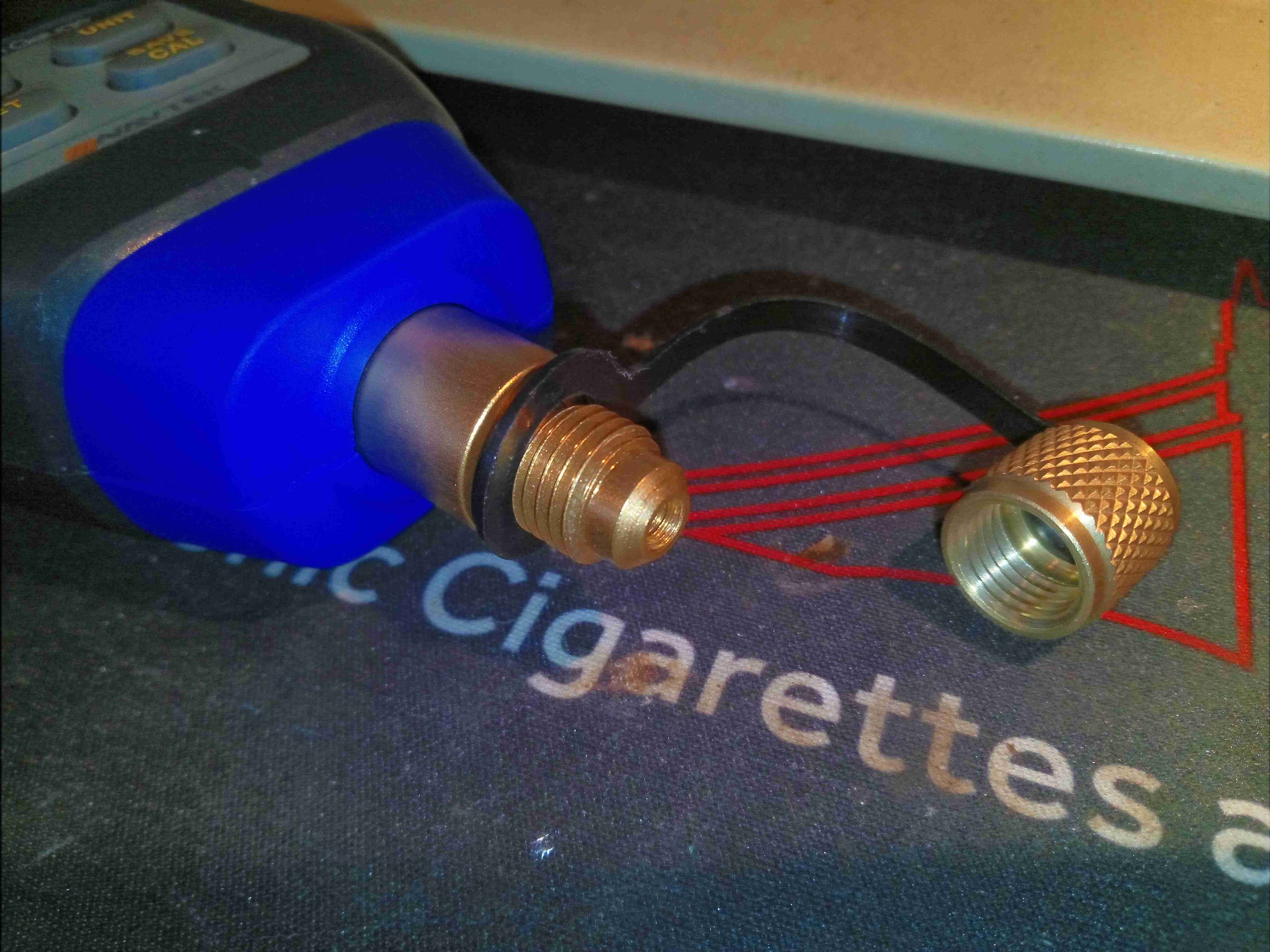
1/4″ SAE Flare Fitting
The brass fitting at the end of the unit holds the 1/4″ SAE flare port for attaching to the system under service.
Main PCB
Removing 4 screws on the back allows the casing to come apart. Some quite simple circuitry in this unit. There’s the usual STM8 microcontroller which is very popular with the Chinese manufacturers, a beeper, along with some passives & support components. The vacuum sensor is on the left.
Vacuum Sensor
Here’s the brass block that houses the vacuum sensor itself. According to the manufacturer, this is a Pirani sensor, but I have no way to confirm without destruction of the unit. There’s a built in temperature sensor in the brass block, and the front end of the circuitry is (assuming my decoding of the SOT-23 component markings is correct!) taken care of by a TS507 precision R2R Op-Amp. There’s also a TSX561 micropower wide-bandwidth Op-Amp, along with an LD39020 LDO linear regulator for power supply functions.
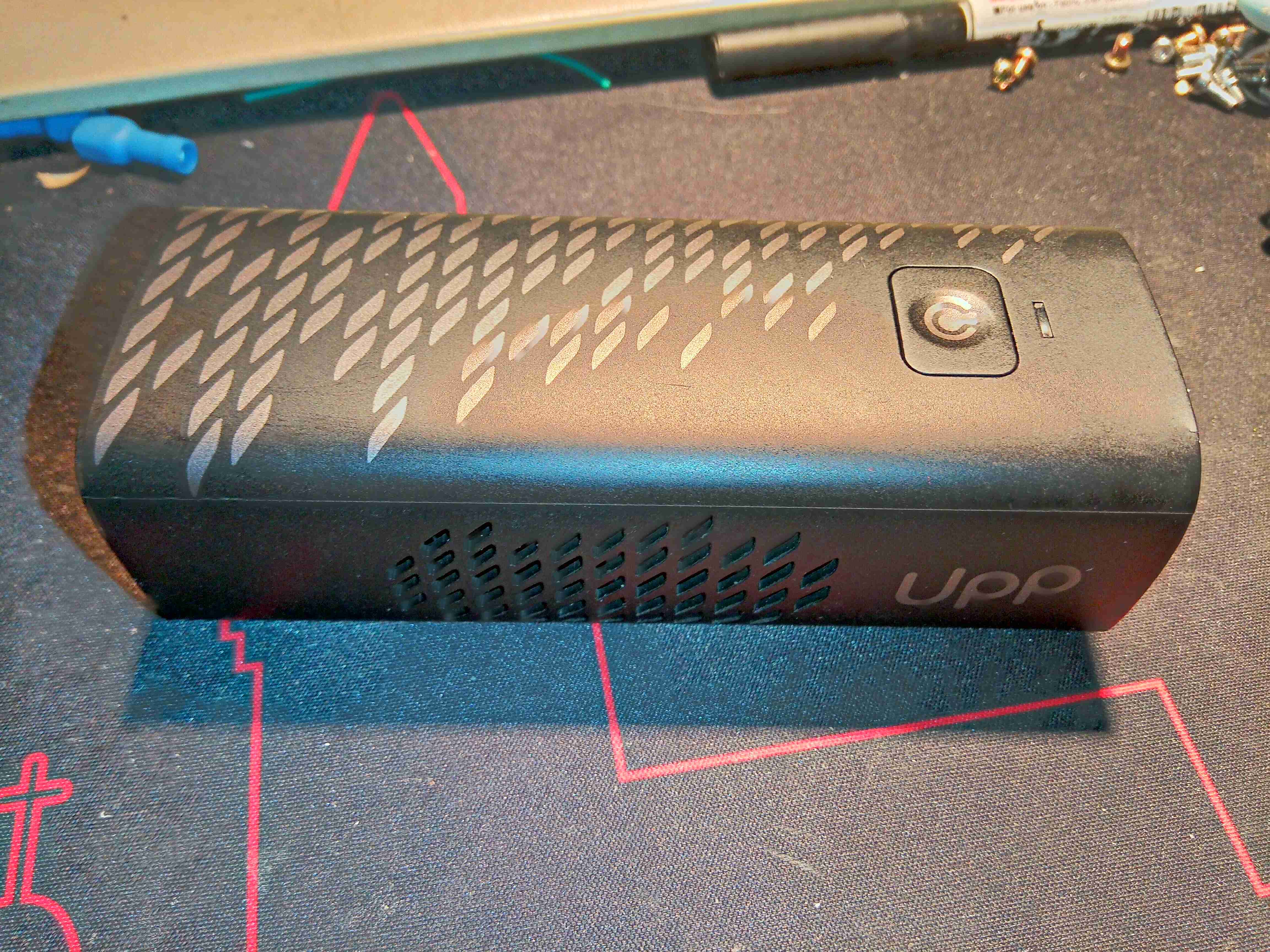
After watching Mike’s Electric Stuff’s video on these a while back, I figured it was time to grab one from eBay & see for myself how pointless a tech these are. As far as I am aware, these units are no longer available, the domain name redirects to a company site with no mention of them, and getting cartridges refilled might not be possible without some DIY engineering. These are a small portable Hydrogen-powered PEM (Proton Exchange Membrane) Fuel Cell unit, with a USB output port for charging mobile devices. There’s quite a few vents on the sides of this device, as there has to be an airflow through the PEM Fuel Cell itself, and the only control interface is a single button on the front of the unit.
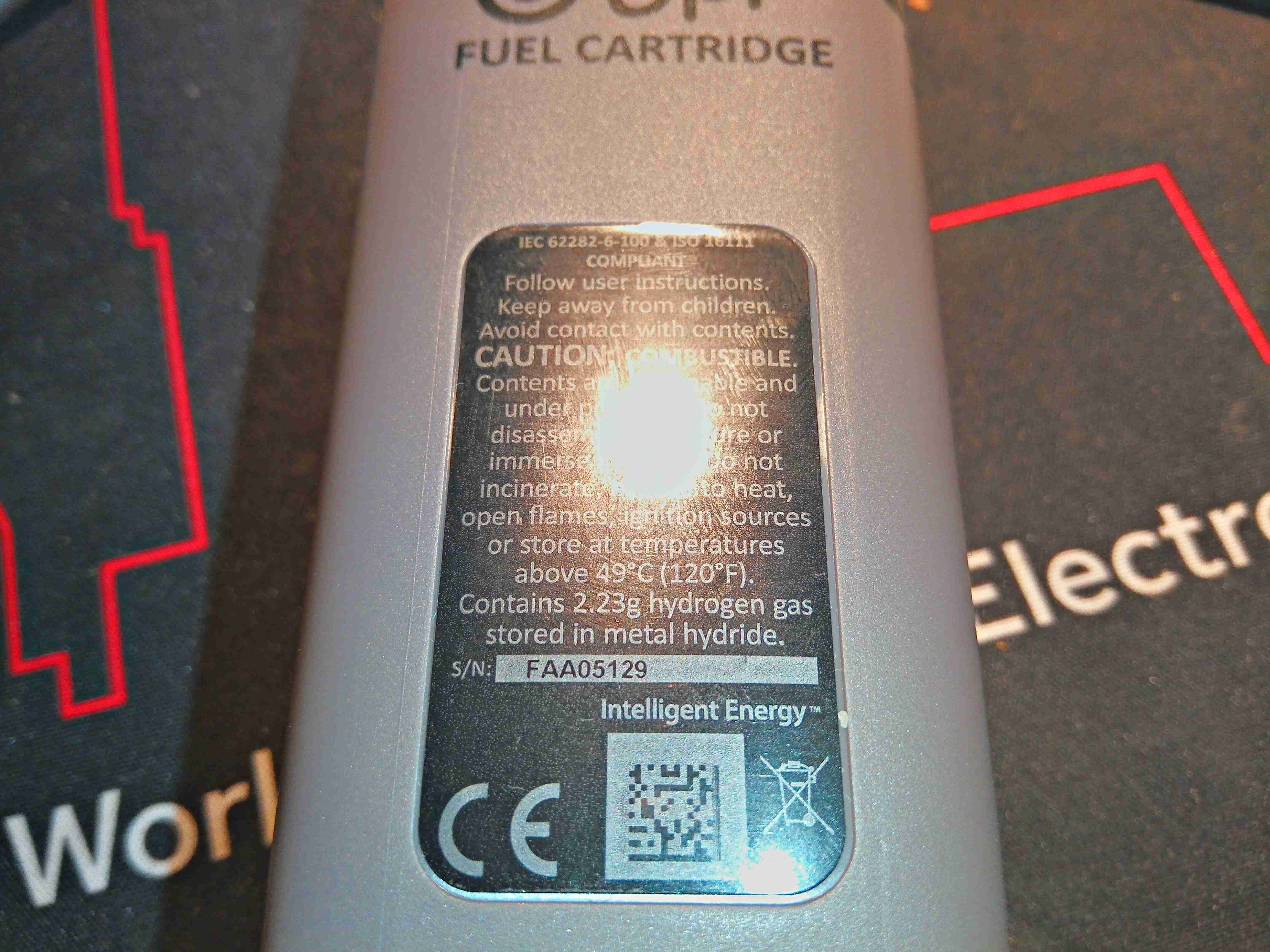
Gas Cartridge
The Hydrogen gas is stored in a cartridge, filled with Hydralloy C5 metal hydride powder. These would be exchanged for a full one when all the gas has been used, at a cost of about £6. (Extra cartridges apparently cost about £50!).
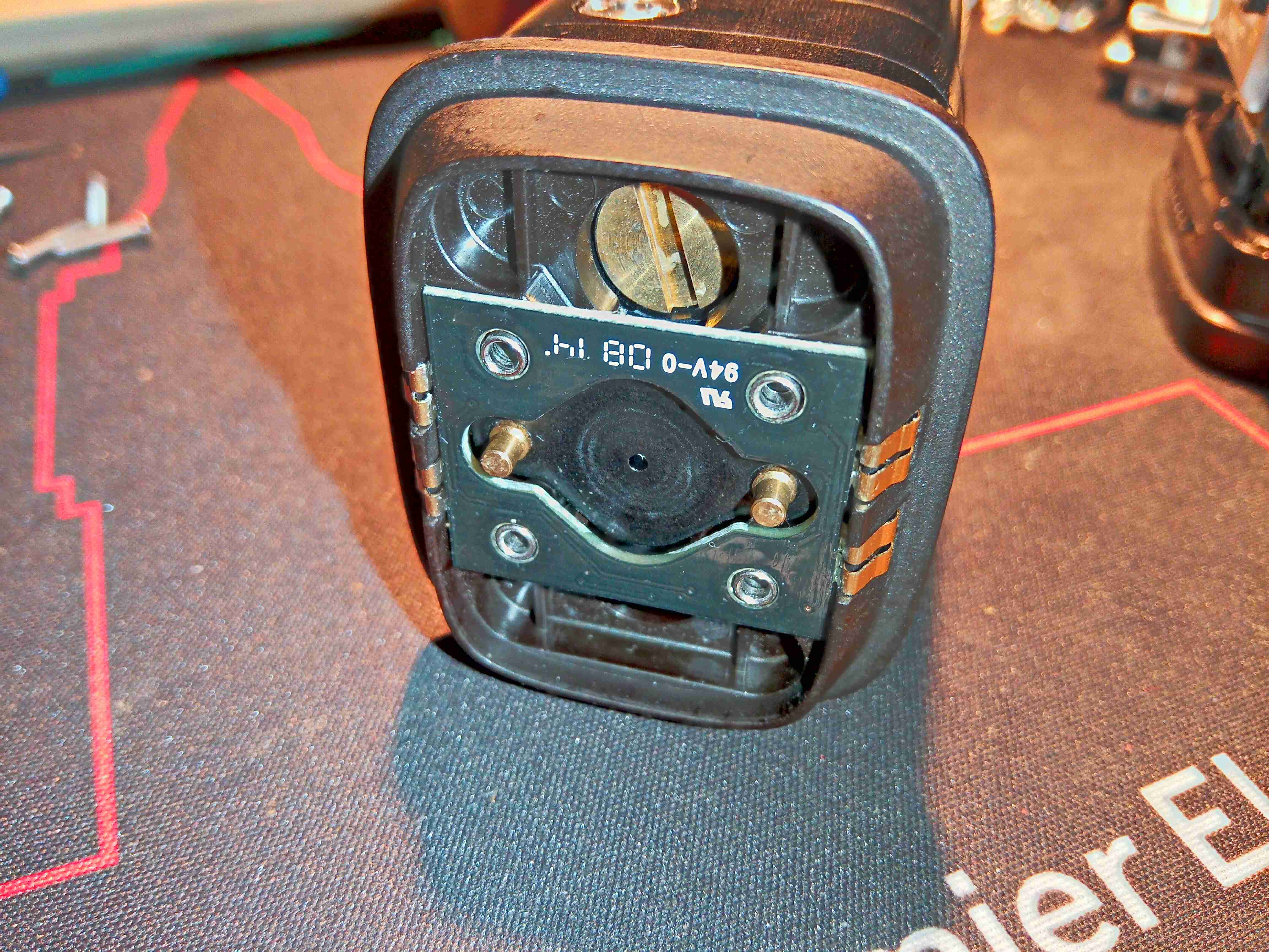
Cartridge Valve
The top of the cartridge holds the main valve, and some contacts. The gas is permitted to flow from the storage hydride by means of the two brass pins on either side of the seal – when these are both pushed down by pins moulded into the bottom of the main fuel cell unit, the internal valve is opened. The contacts connect to an internal PCB with a single EEPROM.
Cartridge Magnets
The cartridge is attached to the fuel cell with magnets – there are a pair of very powerful NdFeB magnets behind the main steel plate on the top, and a matching pair inside the bottom of the fuel cell assembly.
Cartridge EEPROM PCB
Removing a label allows access to 4 screws, which hold the top assembly onto the pressure vessel section of the gas cartridge. Here is the internal PCB with it’s EEPROM, and the large brass screw which may be for regulating the gas flow rate.
Gas Cartridge EEPROM
Removing the PCB allows us to see the EEPROM itself – a 2kBit part, which contains information like remaining gas charge, and serial number. When the cartridge reads empty according to this EEPROM, the cell will stop functioning. Luckily however, it is happy to operate without this PCB even being present – I expected the unit to spit & error & shut down if it couldn’t communicate over the I²C bus with this memory.
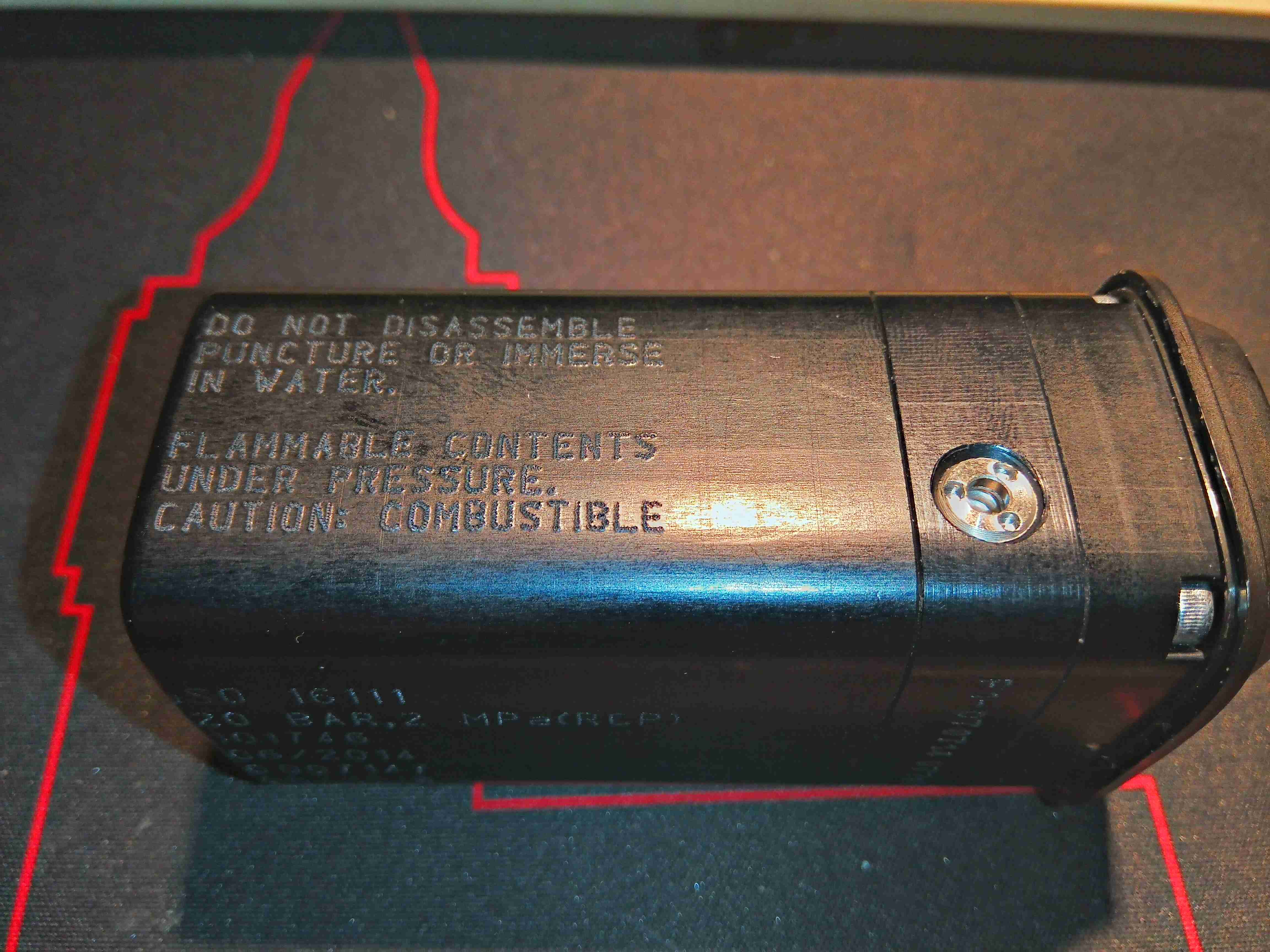
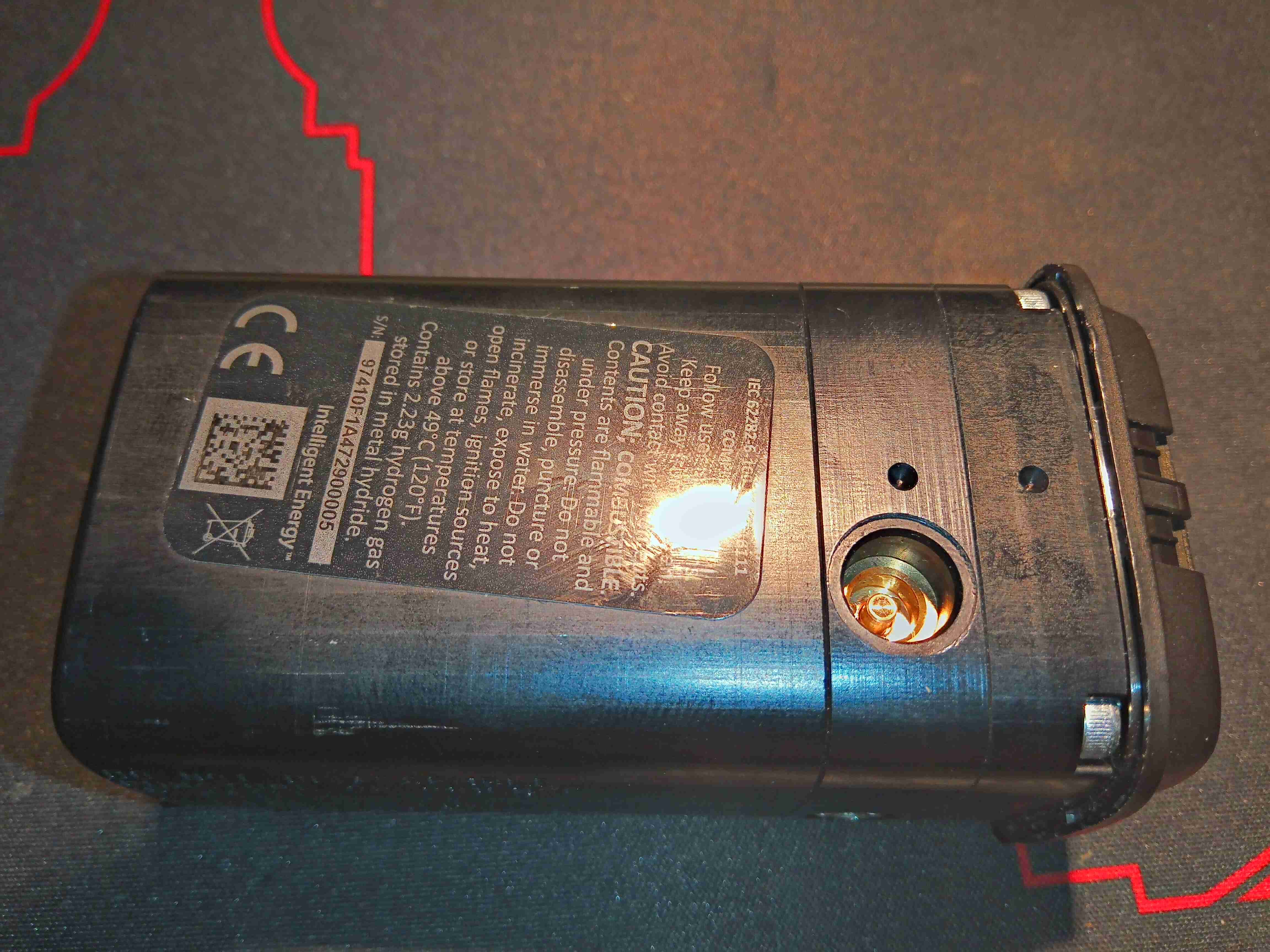
Pressure Relief Valve
Removing a screw in the base of the casing (hidden under a label) allows the plastic shell to come off, revealing the aluminium pressure containment to be seen. There’s a pressure relief valve on the side here, and some warnings about what not to do with the thing.
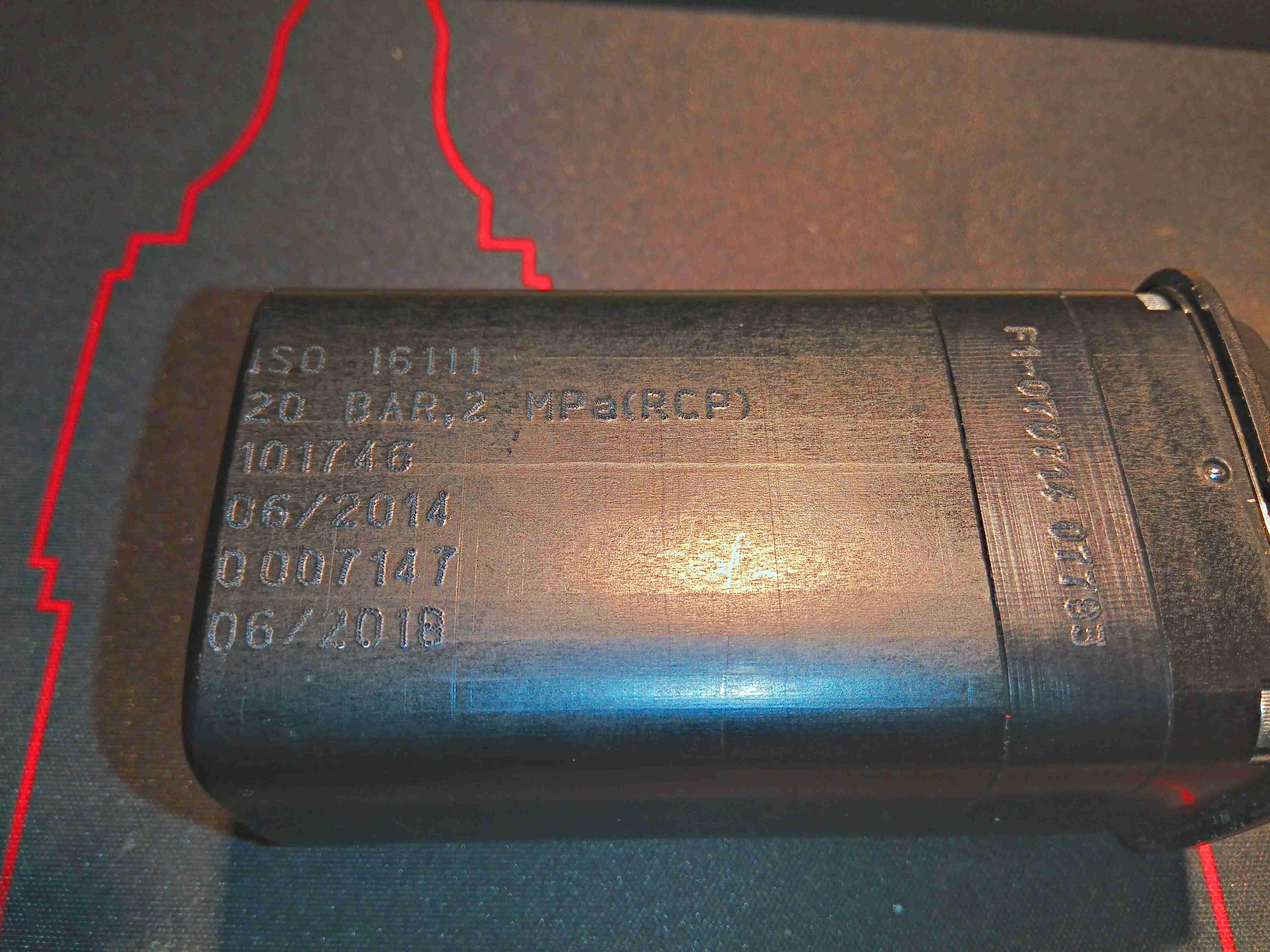
Pressure Vessel Info
Some more info on the other side, with the ISO standard this cell is rated to, and the 20 bar Rated Charging Pressure. There is also a stamp indicating how long the certification of the vessel lasts. This one is rather out of date…
Charging Valve
The opposite side of the unit has another label covered in warnings, and a recessed charging valve. It’s an interesting one this – there are no threads, just a brass valve with a depressable pin in the centre to allow the gas to flow. Since this needs to be charged at 20 bar, a special jig would be required, to hold any charging adaptor in place while the gas is injected. There’s no chance of getting the official part for connecting to this, so I intend to machine a brass adaptor to connect here for charging.
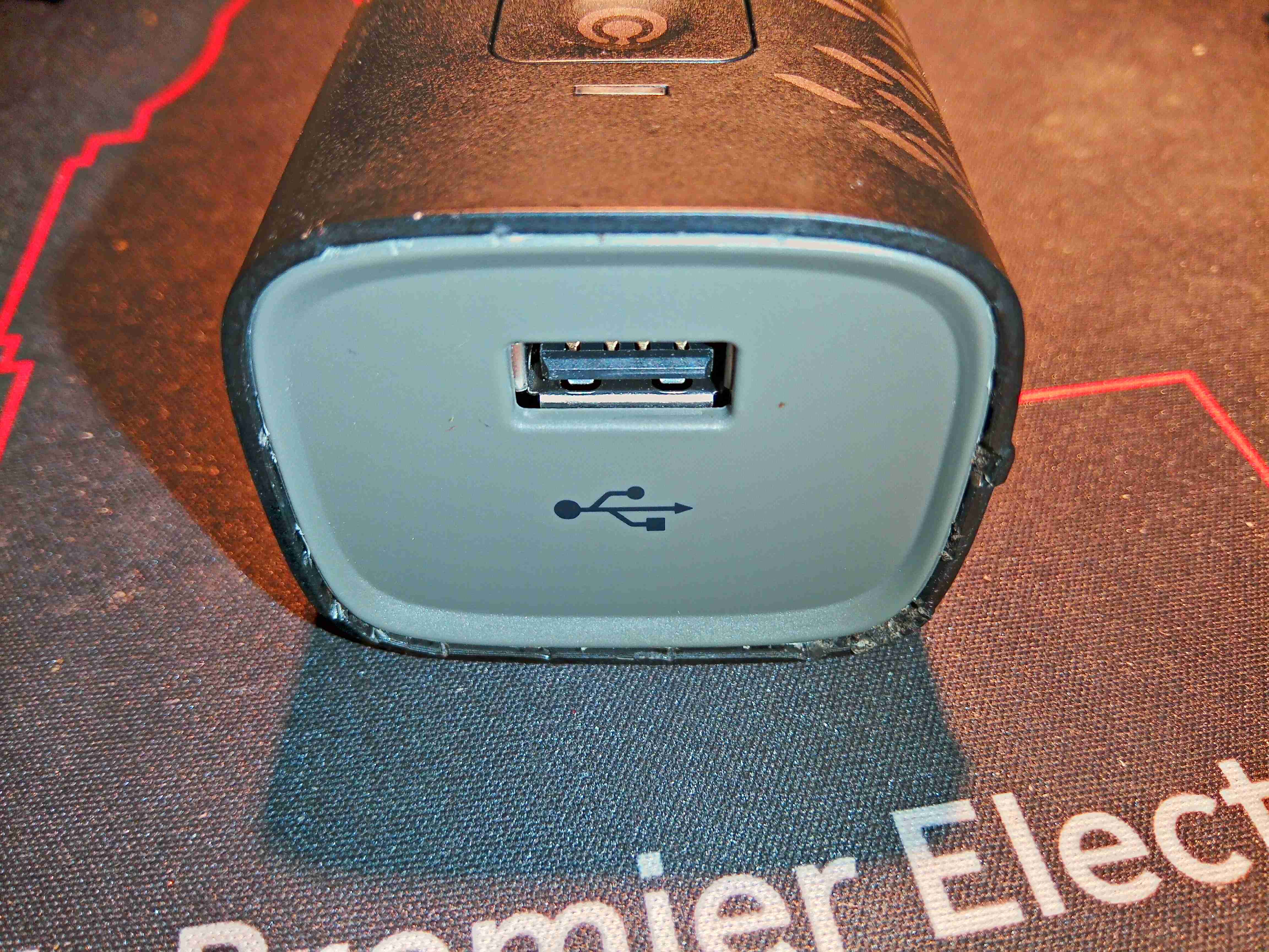
USB End
The top end of the fuel cell unit has a single USB port, rated to 1A according to the rating plate:
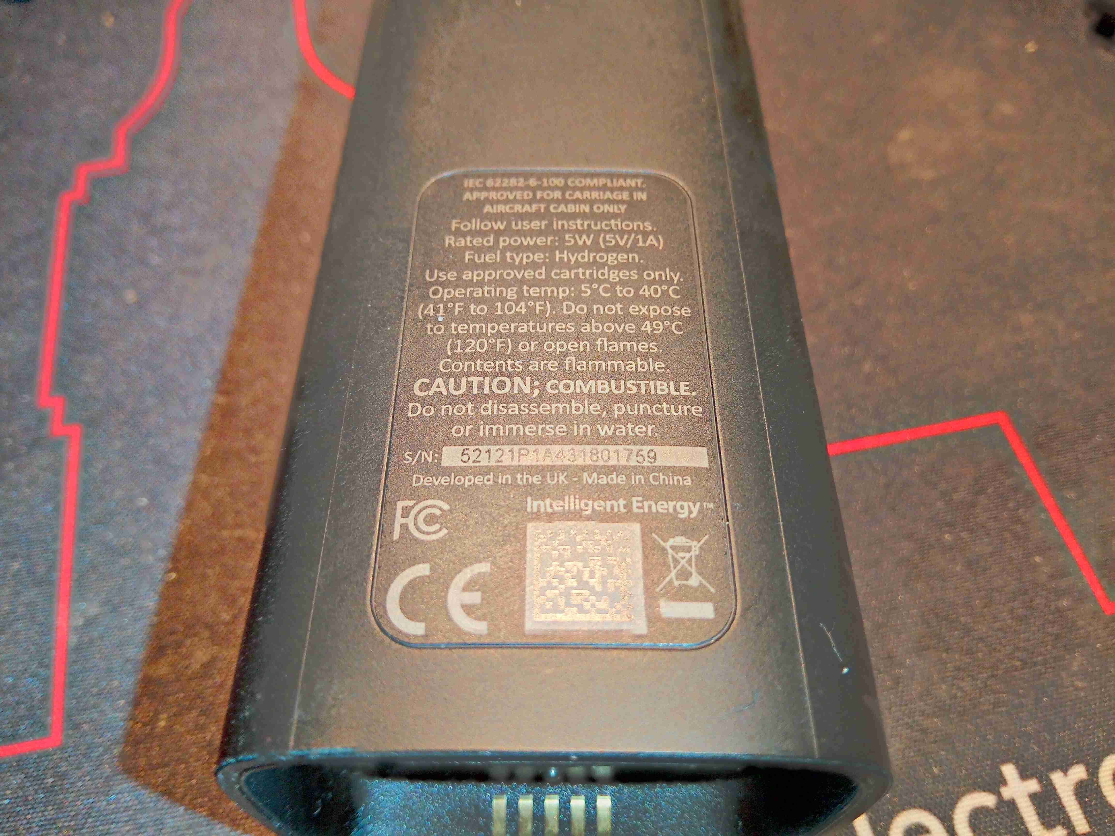
Rating Plate
Standard rating plate with some regulatory markings, and output power.
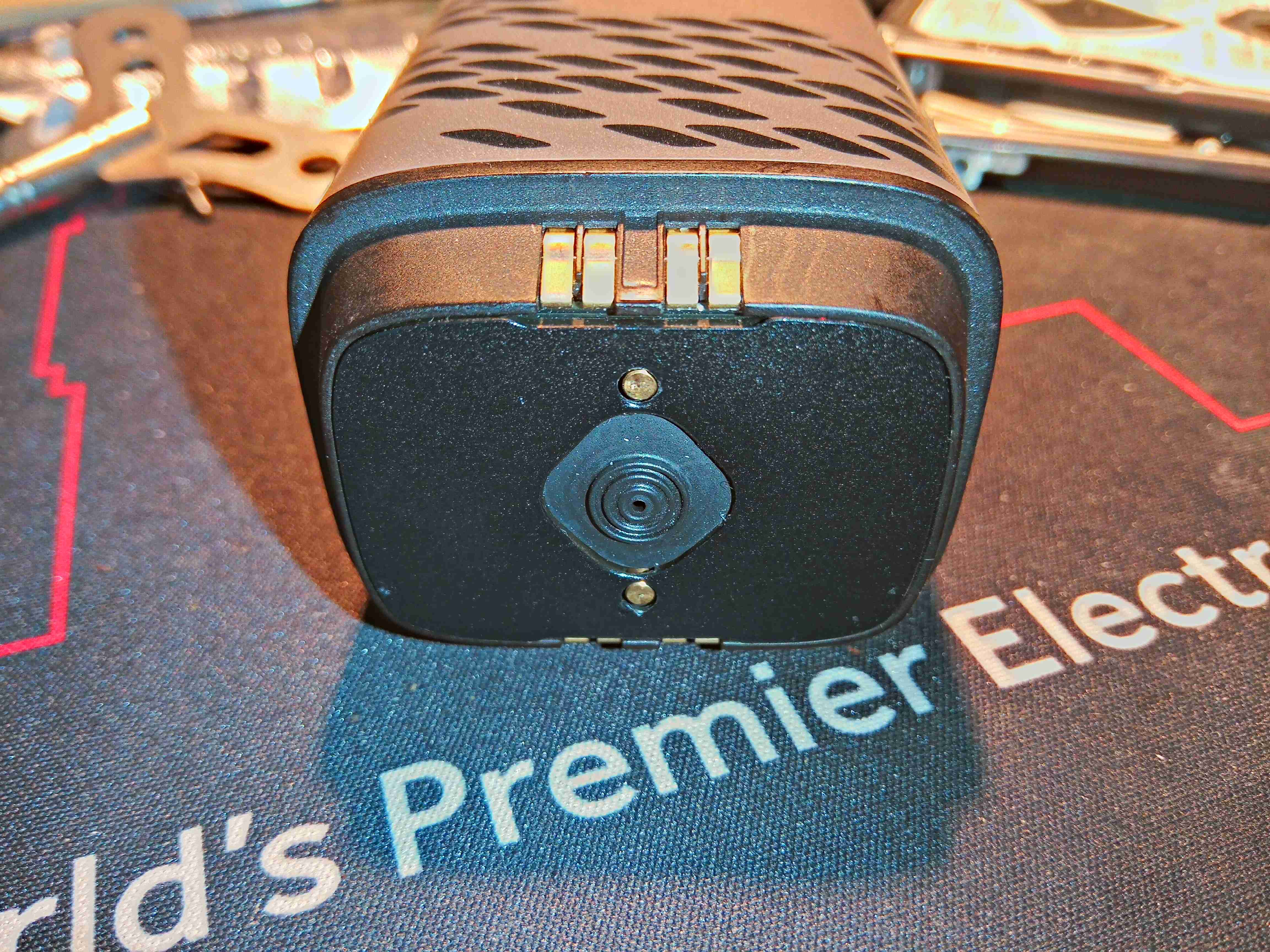
Gas Inlet
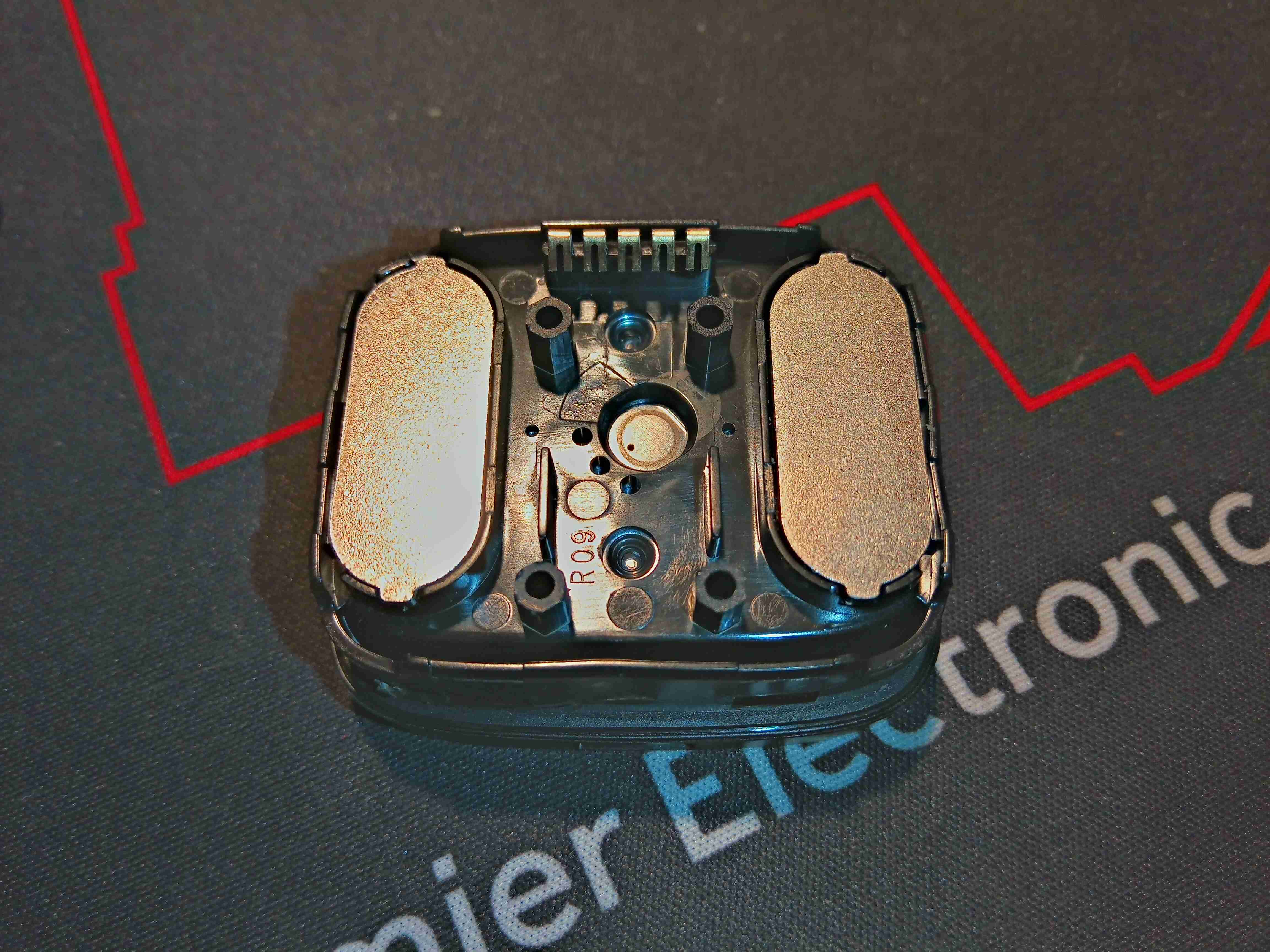
Here is the bottom of the fuel cell unit, which magnetically couples with the gas cartridge. The two pins either side of the gas port are visible, and it is these which open the valve on the cartridge. The 5 gold-plated contacts at the edge make contact with the spring terminals on the EEPROM PCB on the gas cartridge for communications. They are also used with a separate base for external charging of the LiPo cell contained inside. More on this later.
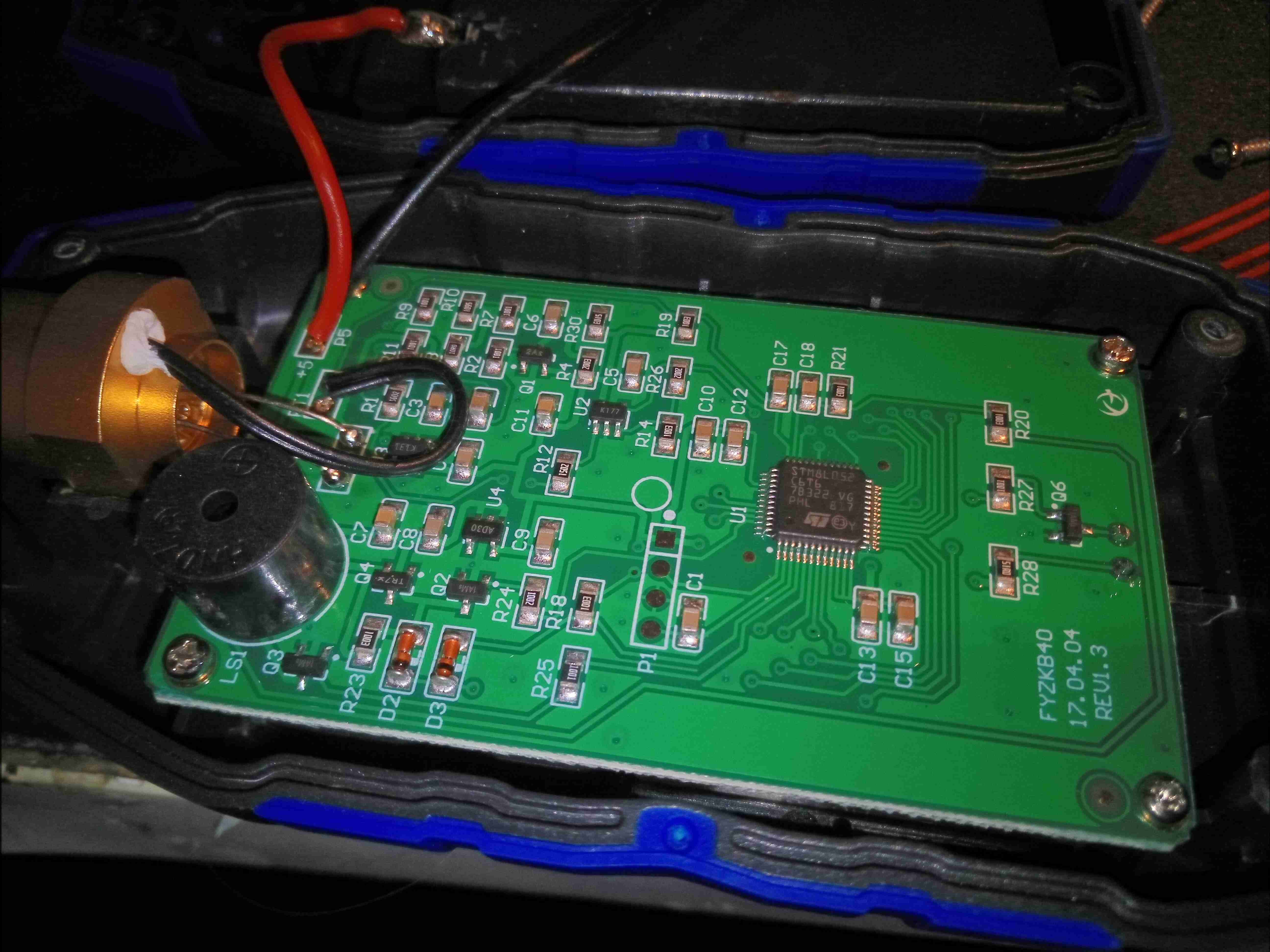
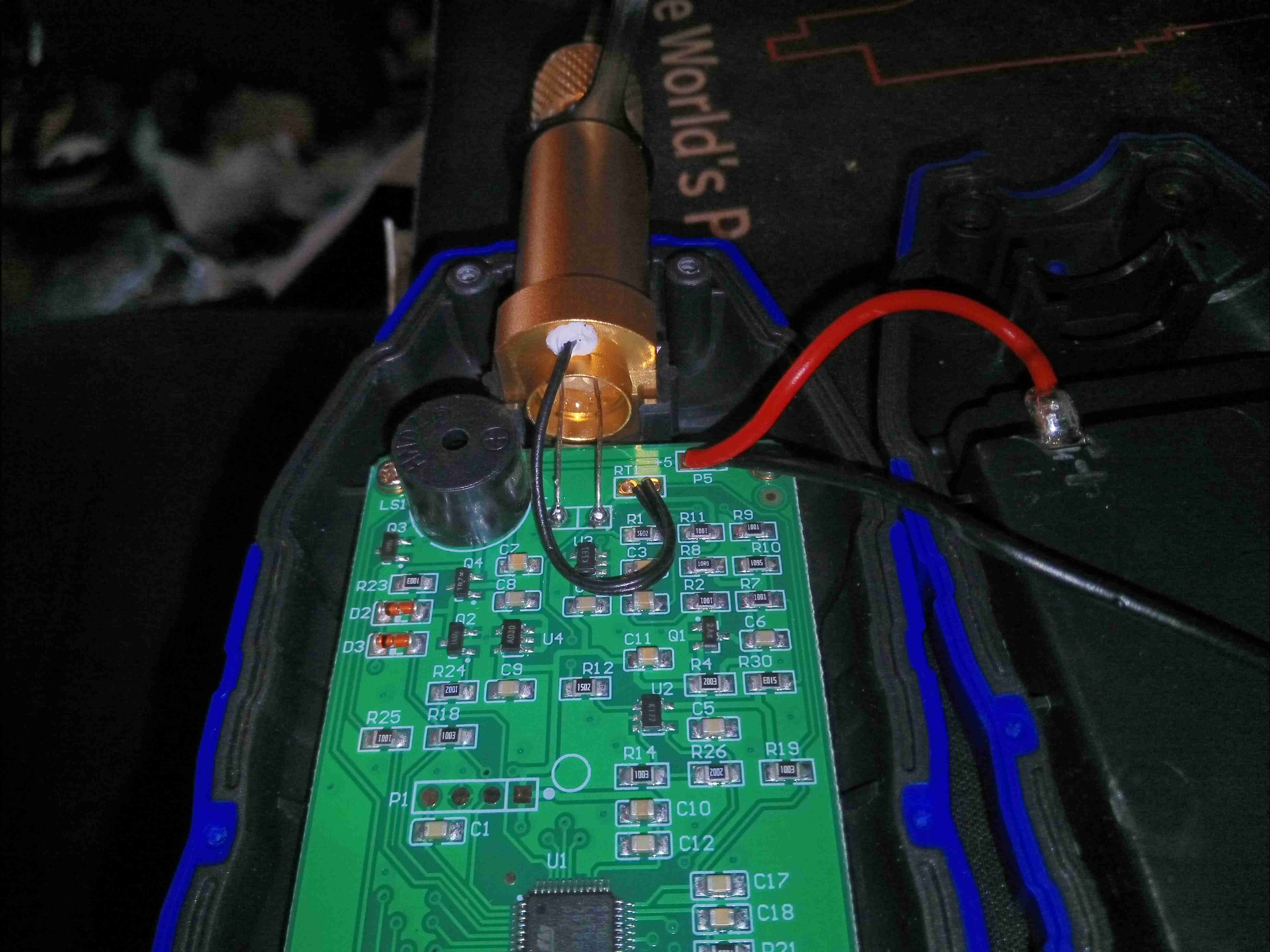
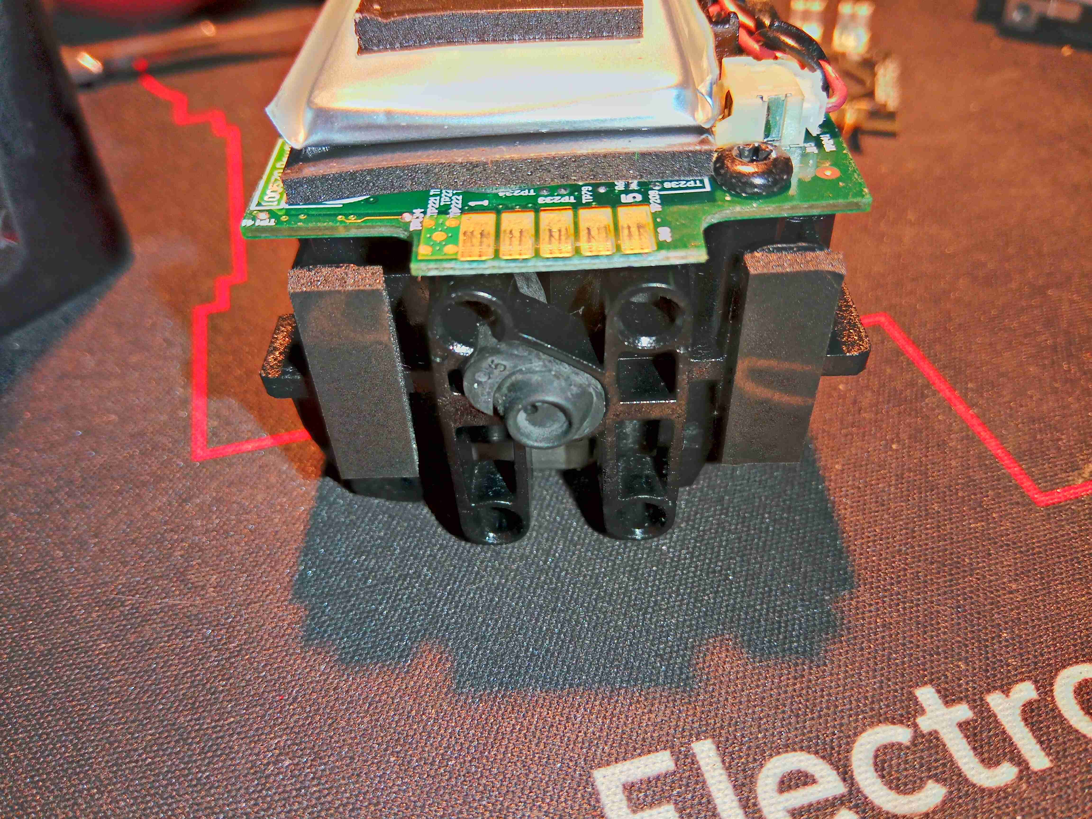
Internal Frame
The main body of the cell is secured together with internal clips – and are not intended to ever be opened without damage, but here is the core of the unit. There’s a large Lithium Polymer cell on the top of the main board, which is required to actually get the unit going in the first place. I suspect this is also used to buffer the output from the PEM cell itself, and provide the maximum of 1A output current. (My unit would not charge a device even at 500mA when it arrived, until the internal cell was charged up – a red LED was lit just before the unit shut itself down).
USB Output
The top of the board has the single user button & the USB port. This port is enabled for communications – there used to be an app for phones that would show some statistics about the unit to the user.
PEM Fuel Cell Connections
Turning the unit over shows the PEM Fuel Cell itself, a stack of 5 plates in series. There are 5 connections into the cell unit – main power output terminals, and a pair of terminals for a thermistor, which is buried right in the centre of the cell at the top, to measure operating temperature.
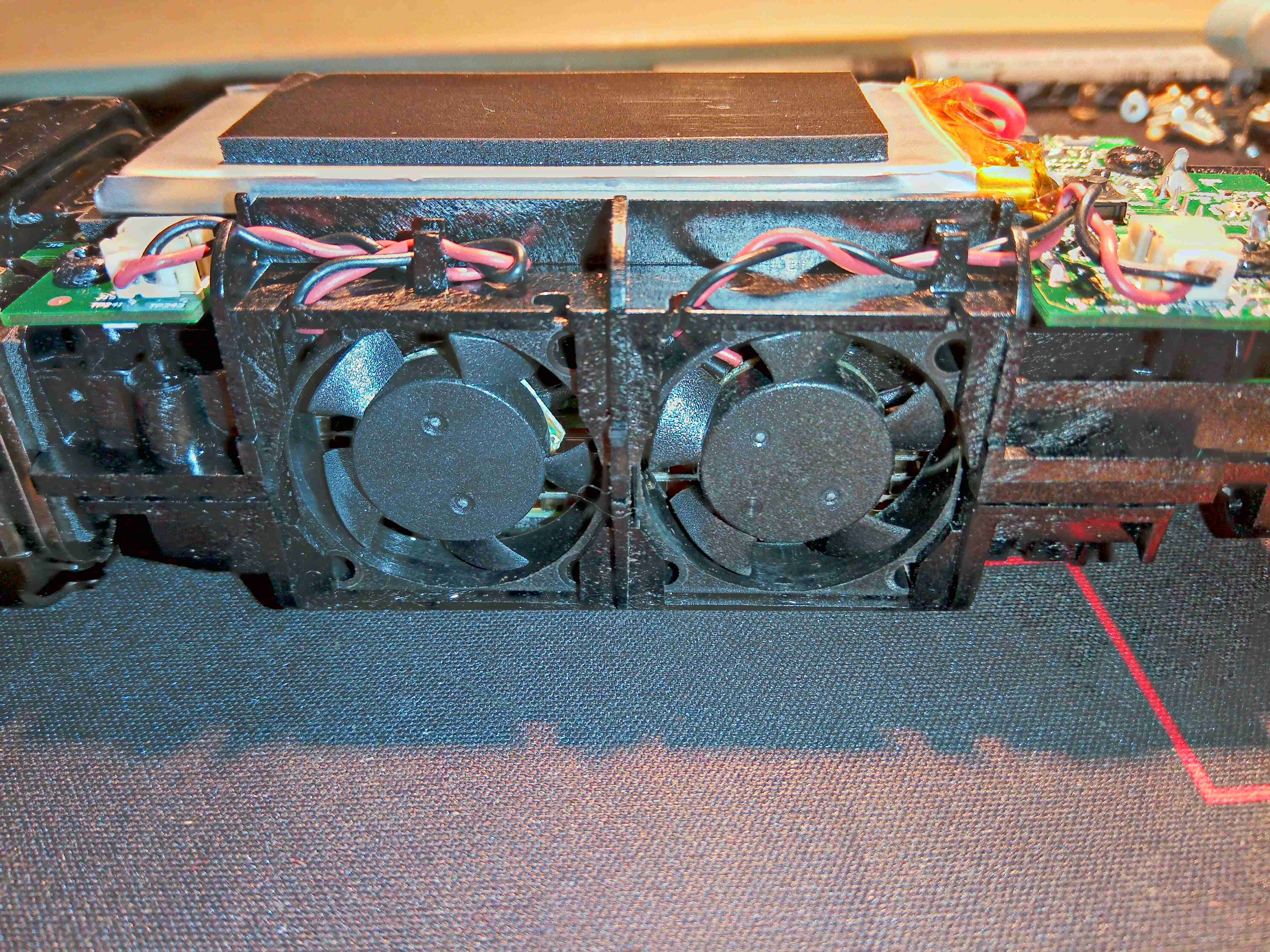
Cooling Fans
The other side of the frame holds two tiny fans, which waft some air through the channels in the fuel cell plates. This will both be for cooling, and to ensure that Oxygen can get into cell assembly to react with the incoming hydrogen.
Fuel Cell Frame
The fuel cell unit clips off the top of the main frame, exposing the two gas control valves. The one on the left regulates the gas input from the cartridge, while the one of the right is regulating the gas outlet to atmosphere. There is also the port of a pressure sensor popping up to the left of this outlet valve.
Fuel Cell Gas Ports
Here’s the bottom of the fuel cell module, with a pair of rubber seals on the gas ports, which interface with the faces of the valves. The H² gas inlet port is on the left.
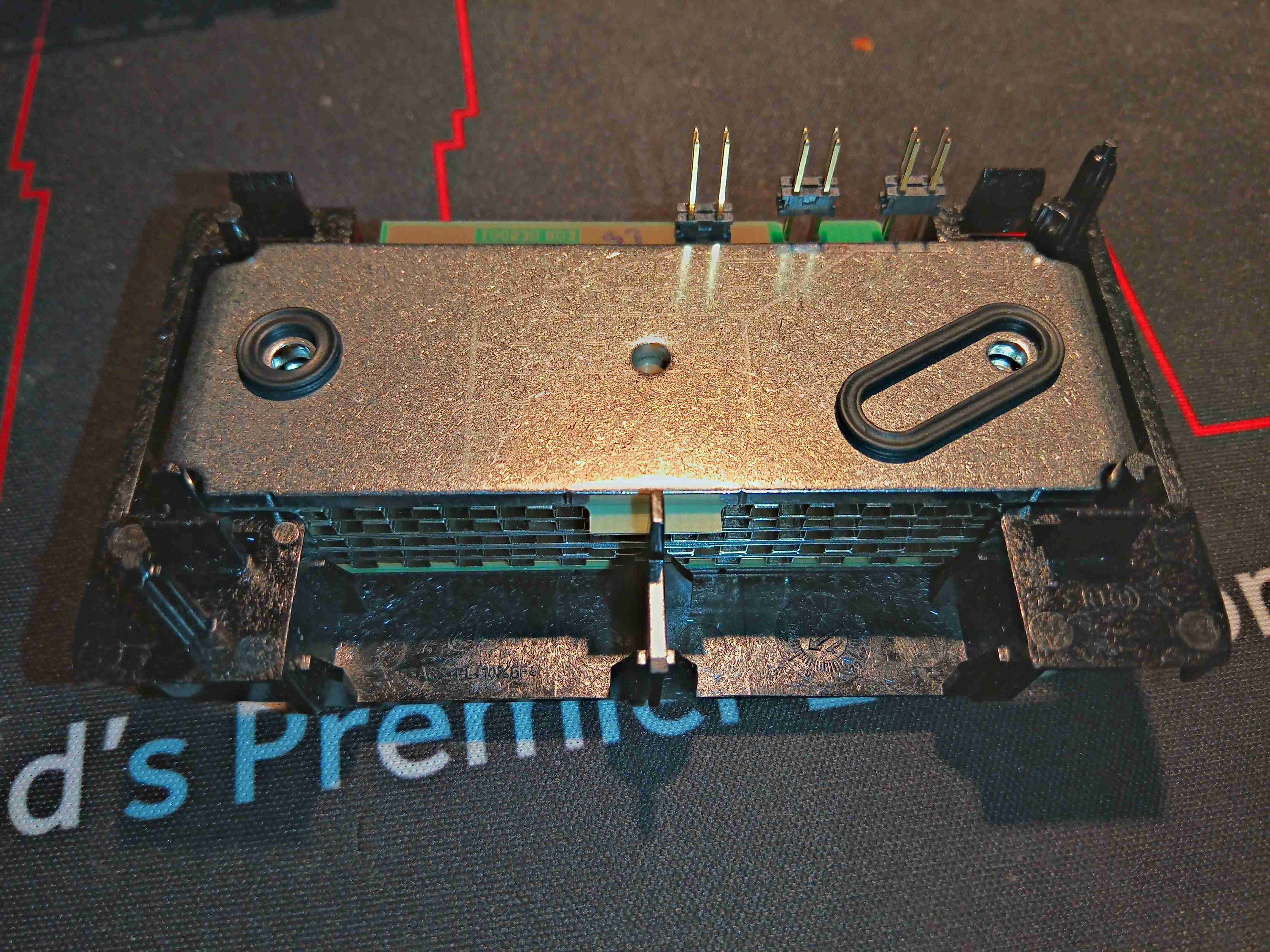
Bare PEM Cell
Some more unclipping of plastic frames allows the bare module to be removed. This is a really heavy-gauge piece of steel to clamp the module together, secured by spring clips.
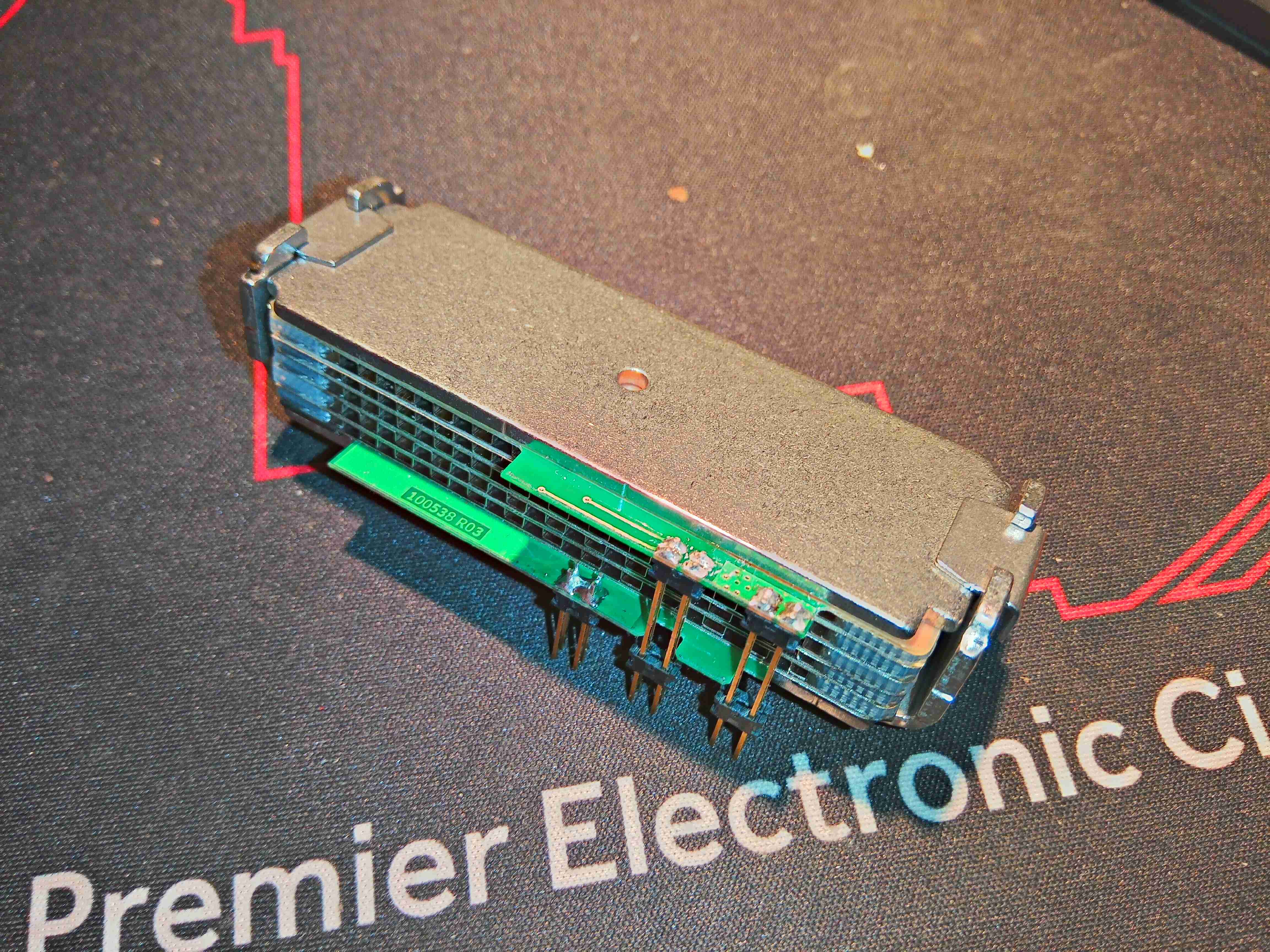
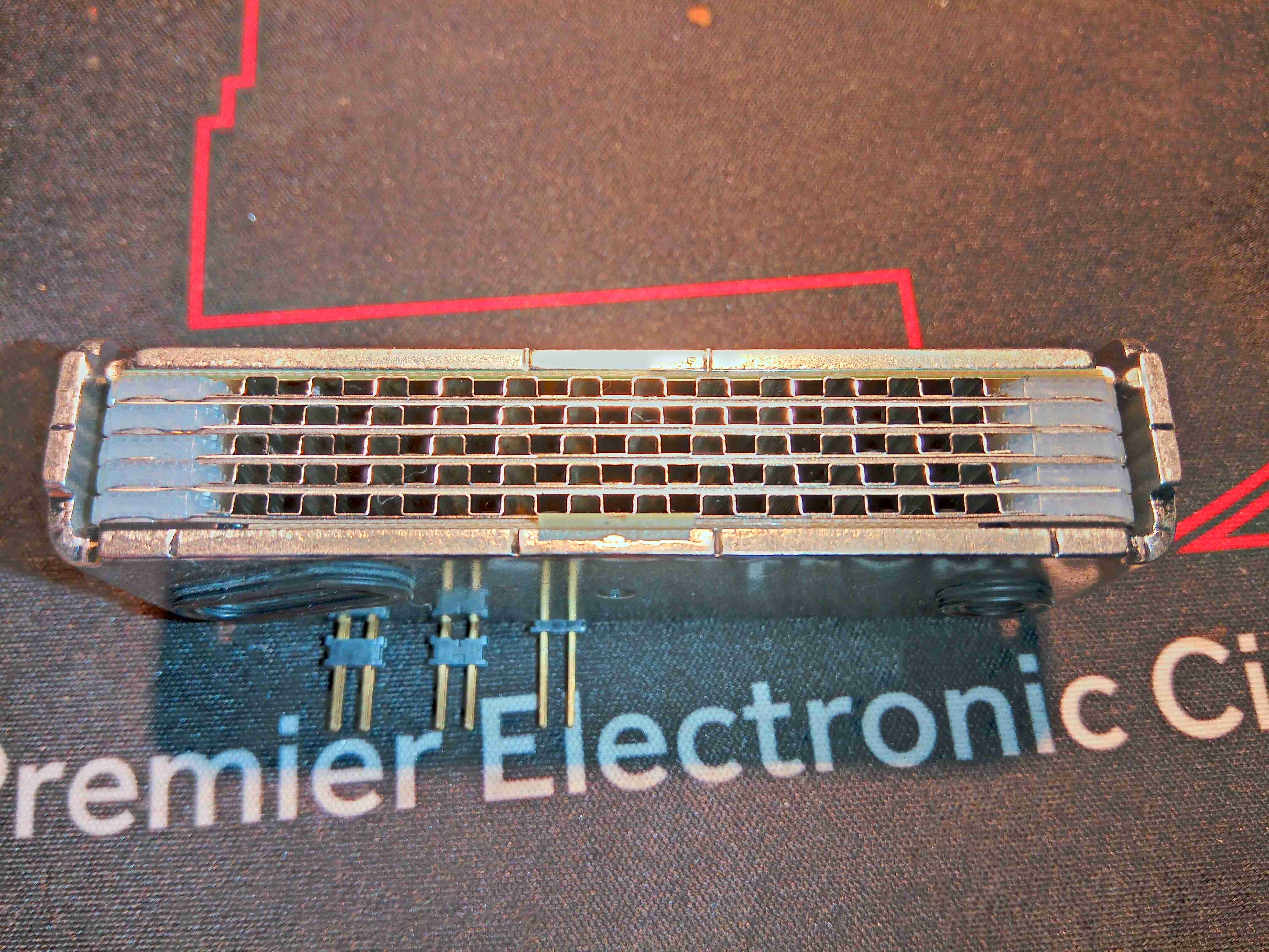
PEM Cell Plates
Here’s the edge of the module, showing the individual plates. There are silicone seals between them to seal the gas ports, and a thin PCB material at the top & bottom as electrical contacts. The plates being stacked together means these are all in series, providing about a 4.6v output voltage.
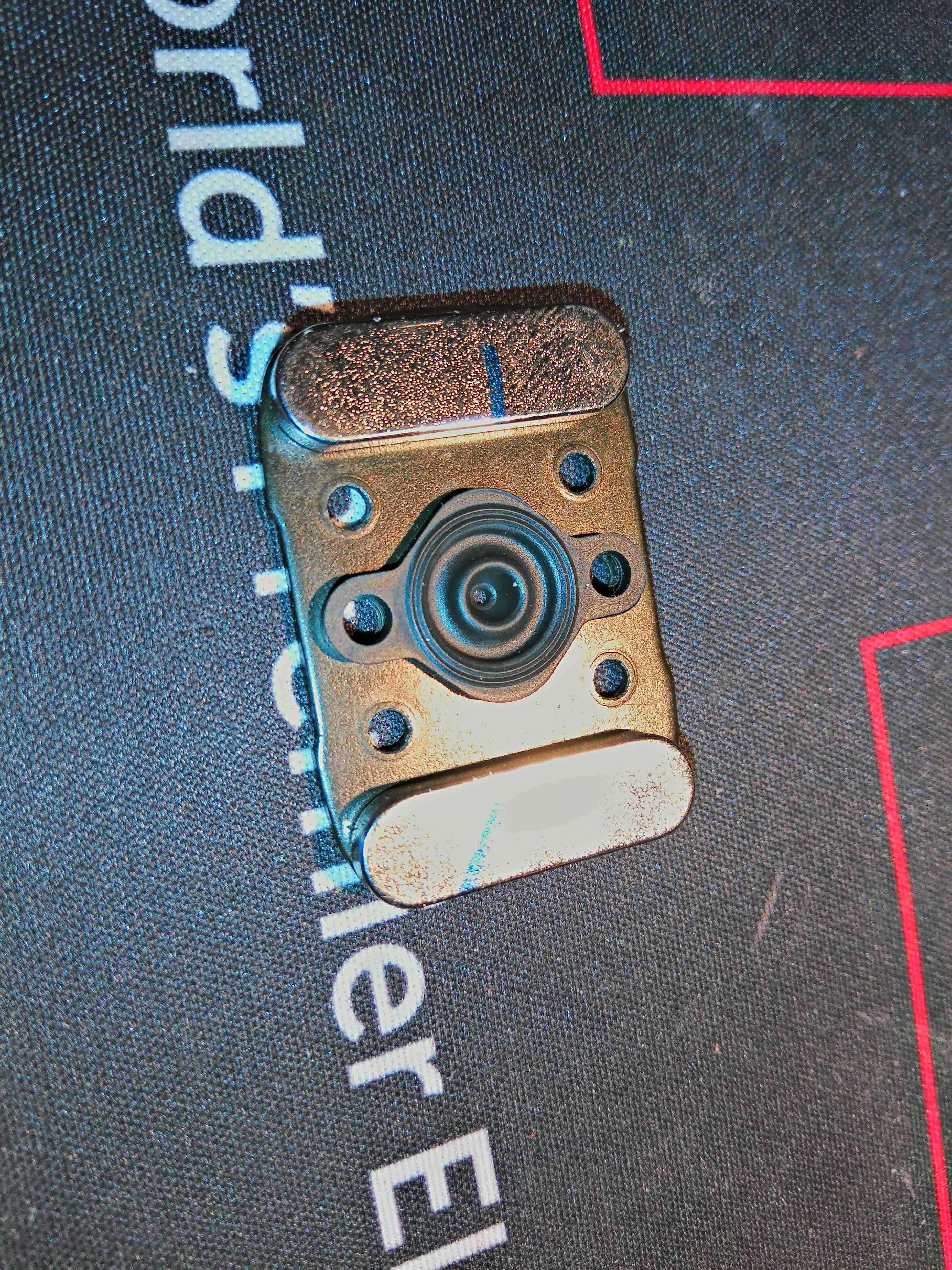
Cartridge Adaptor Plate
Here’s the back of the cartridge adaptor, with the pair of magnets to match the ones on the gas cartridge.
Gas Inlet
This rubber grommet seals onto the metal plate in the adaptor, sealing the gas inside. The 5 contacts are visible here to communicate with the cartridge EEPROM.
PCB Bottom
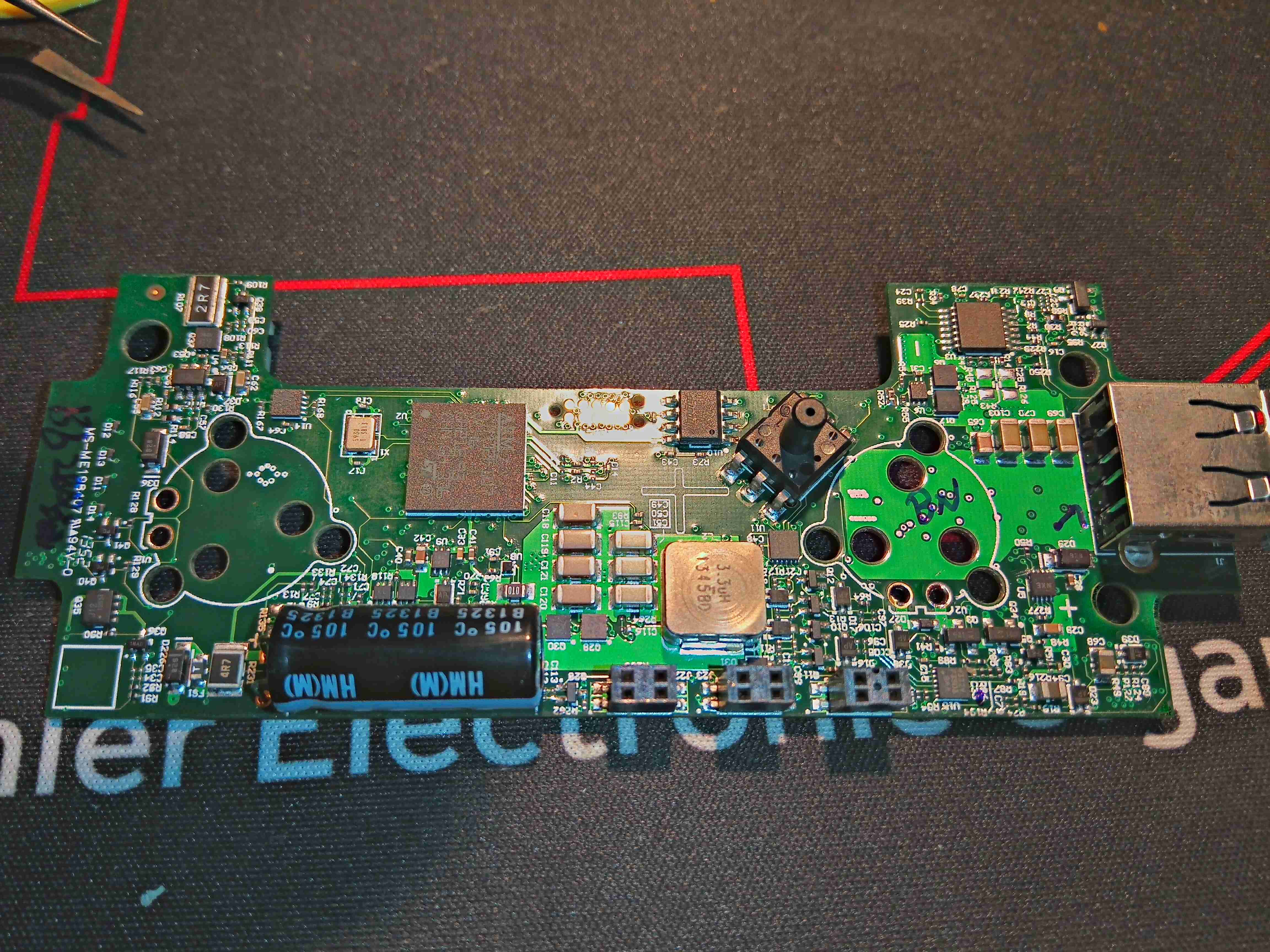
A bit of de-soldering later, and the board is free from the frame. This is very densely packed board, covered in DC-DC converters of various types. The main microcontroller is a STM32F107 from ST Micro – a 72MHz part loaded with interfaces. There’s a small WinBond EEPROM here too, which from Mike’s video, seems to be used for log data. It would be nice to get access to this board through a serial interface, to see if there’s any engineering options left in the software for some tinkering. The large inductor is part of a synchronous DC-DC converter, the controller IC for such is on the other side of the PCB.
There’s a L324A Quad Op-Amp in the top right corner of the board, next to the USB port, along with a load of discreet transistors spread throughout the board. Some of these transistors will be used for switching the solenoid coils on the gas valves. The other major part on this side of the board is the gas pressure sensor, just to the right of the EEPROM.
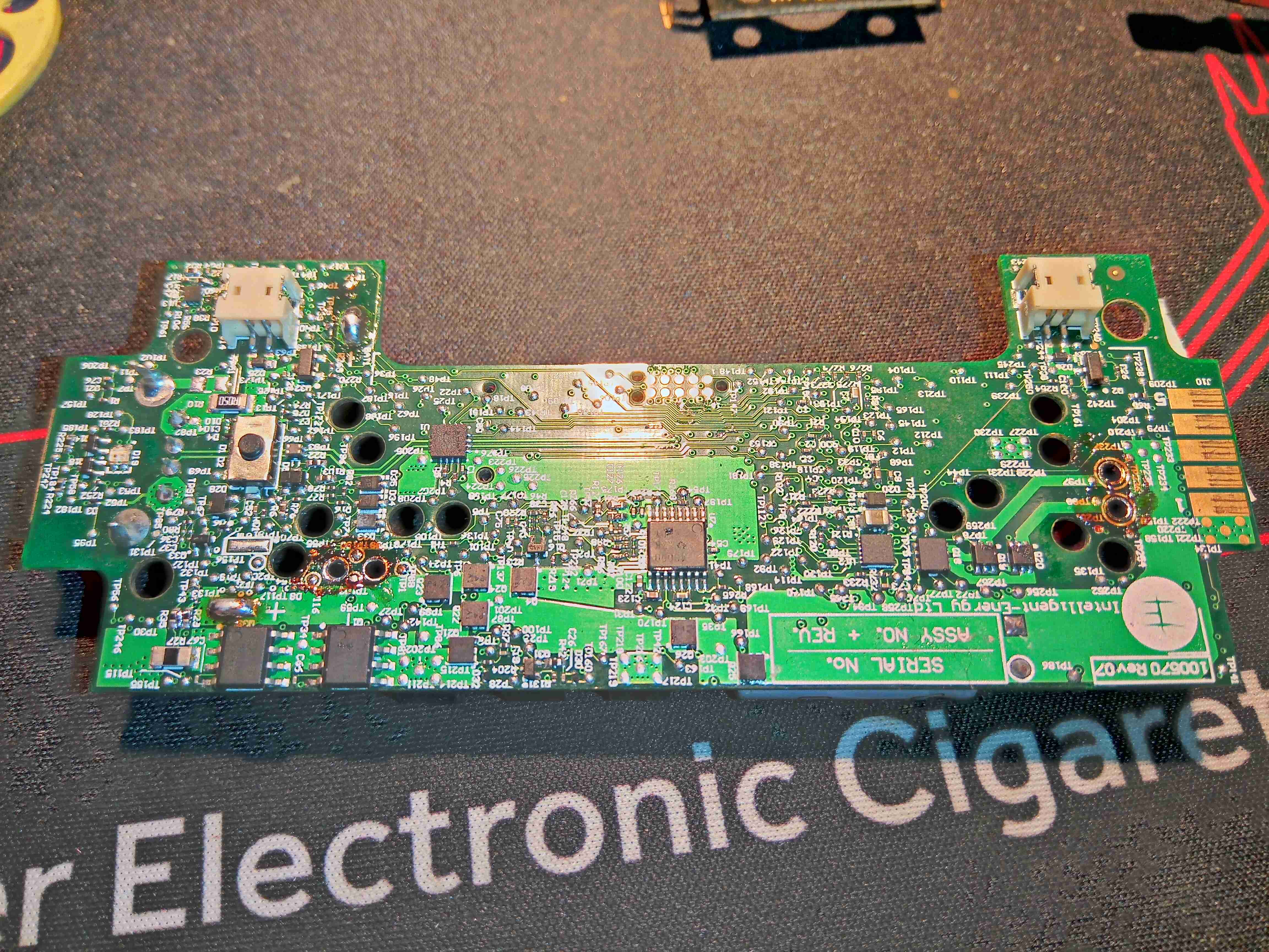
PCB Top
The other side of the board has even more components, the Lithium cell protection MOSFETs are at bottom left, the Synchronous DC-DC converter controller, a TPD43000 from Texas Instruments is in the centre. There are more discreet transistors on this side, for driving the solenoids & fan power control.
Control Valve Cores
Not much remains in the frame, other than the gas valves themselves.
This is an interesting piece of tech, but it’s definitely useless – especially in the era of high capacity power banks of up to roughly 40Ah. The gas cartridges that this unit eats through hold approx. 7Ah of capacity, and at £6 a pop, it is an expensive way to charge a mobile device. I will be coming up with a way of recharging the gas cartridge though, which will involve some sideways thinking & machining of brass. More to come on that!
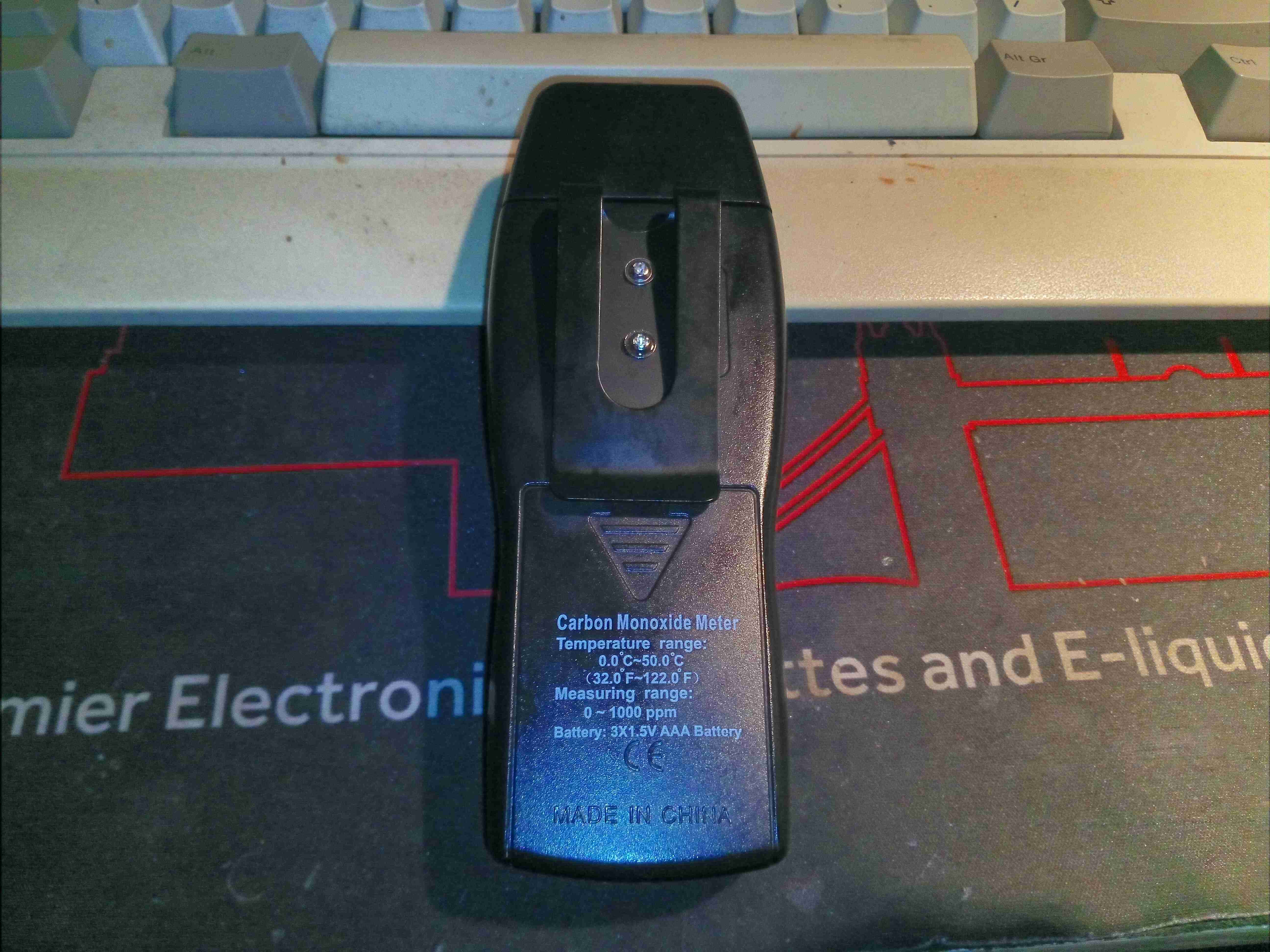
Here’s a handy tool – a Carbon Monoxide meter that range to 1000ppm, with immediate update. Very handy for checking emissions of fuel burning appliances. There’s a large LCD on the front for displaying the reading, and the ambient temperature. There is a user-settable alarm if a high concentration of CO is detected in the air, and High/Low hold modes.
Rear With Belt Clip
The rear of the unit has a belt clip, and the battery compartment which holds 3x AAA cells.
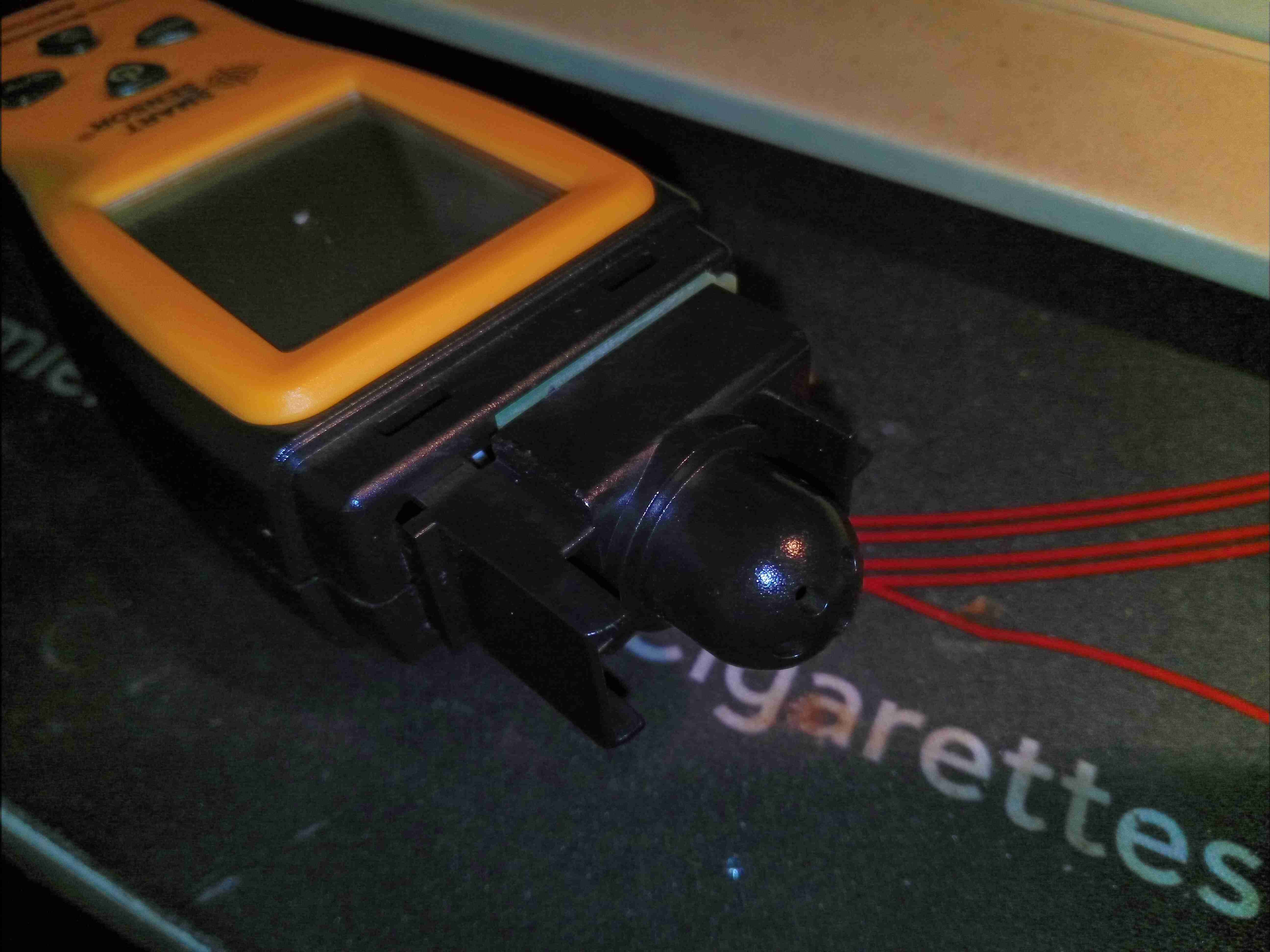
Sensor Cap
Under the decorative cap at the detector end is the sensor module itself, with a thick plastic cap covering the actual sensor.
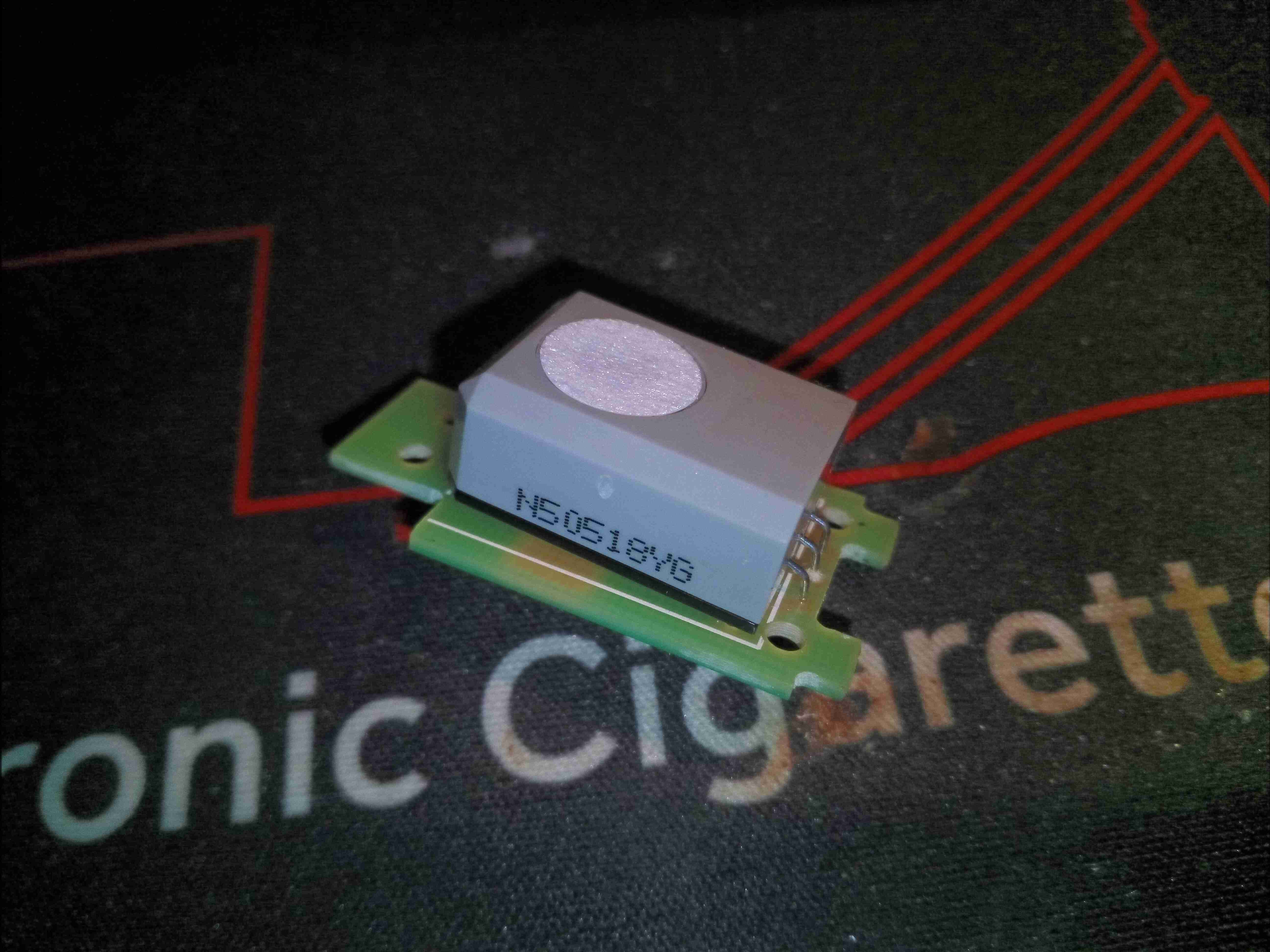
CO Sensor Cell
The CO sensor cell is one of the smallest I’ve seen, a NAP-505 from Nemoto. Easily replaceable with a soldering iron if required after the quoted 7 year lifespan.
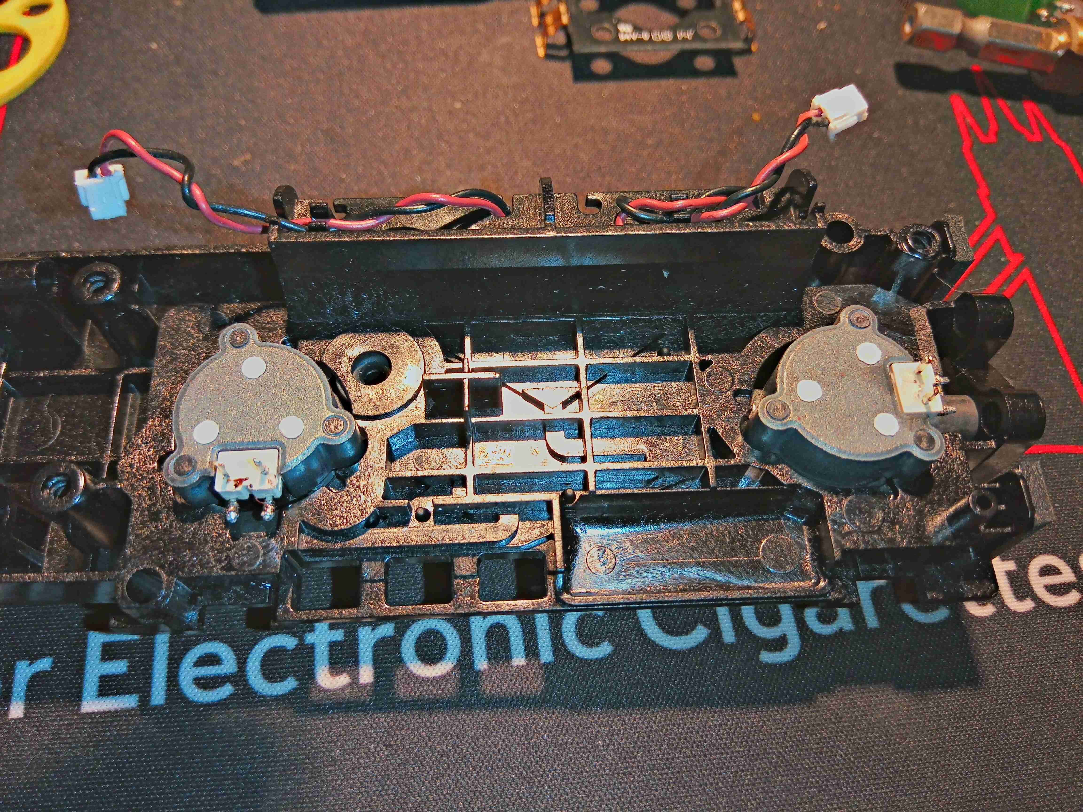
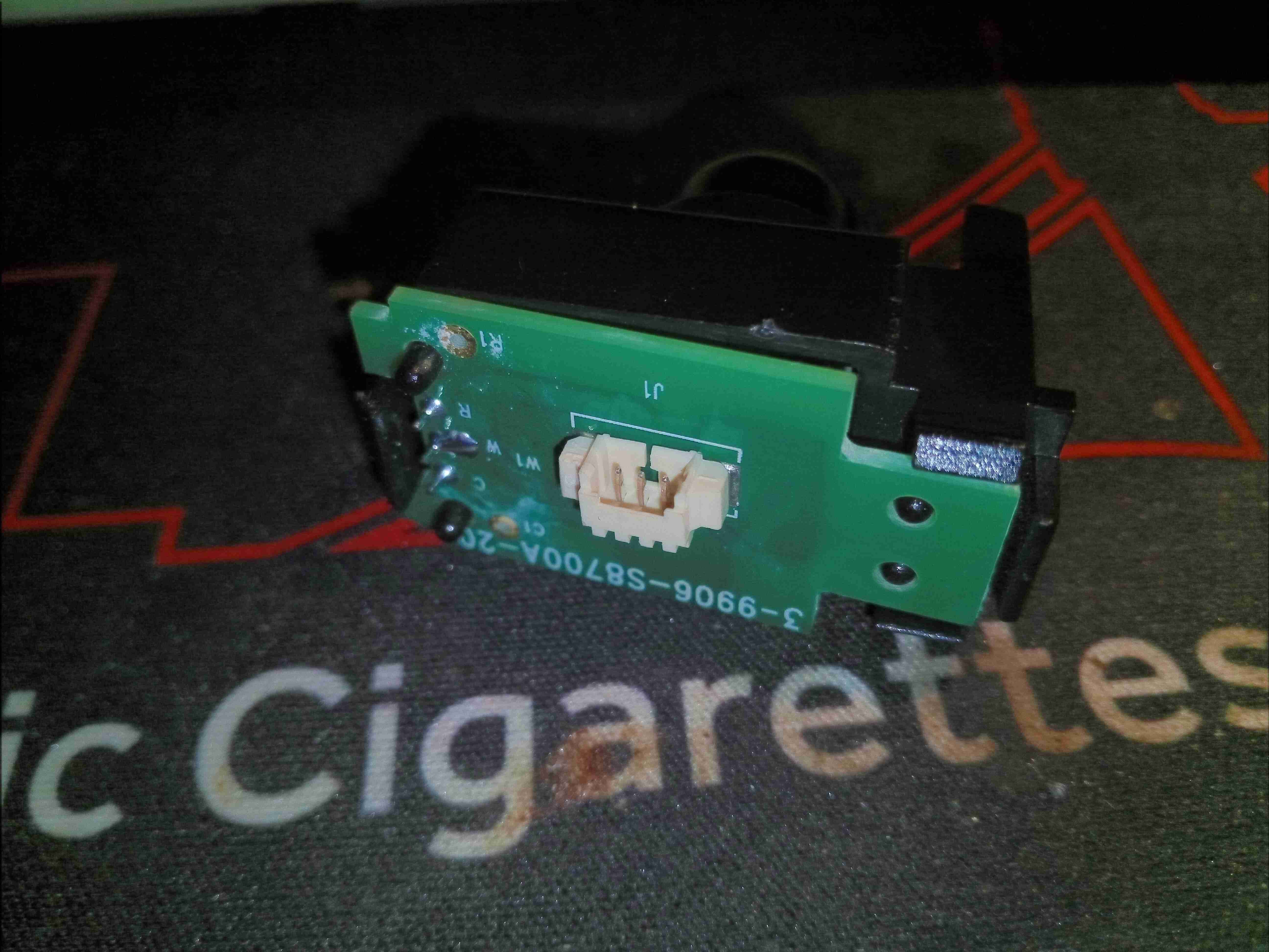
CO Sensor Module
Connections to the main PCB are done through a small 3 pin connector & wiring loom.
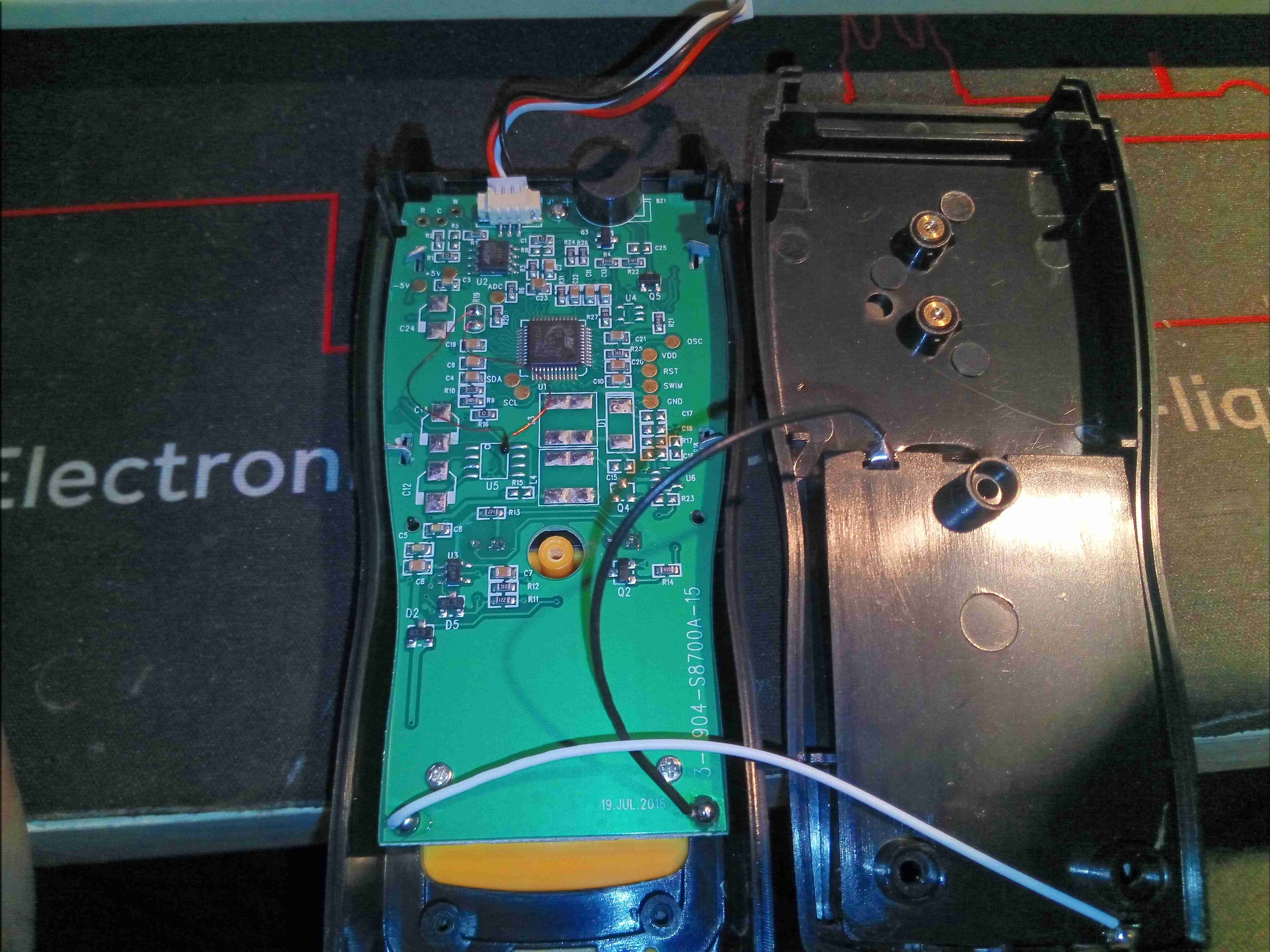
Main PCB
Removing the 3 screws from inside the battery compartment allows the back cover to be removed. The belt clip screws into a pair of brass inserts, which is a nice touch. The sensor connects to the JST connector at the top of the boat.
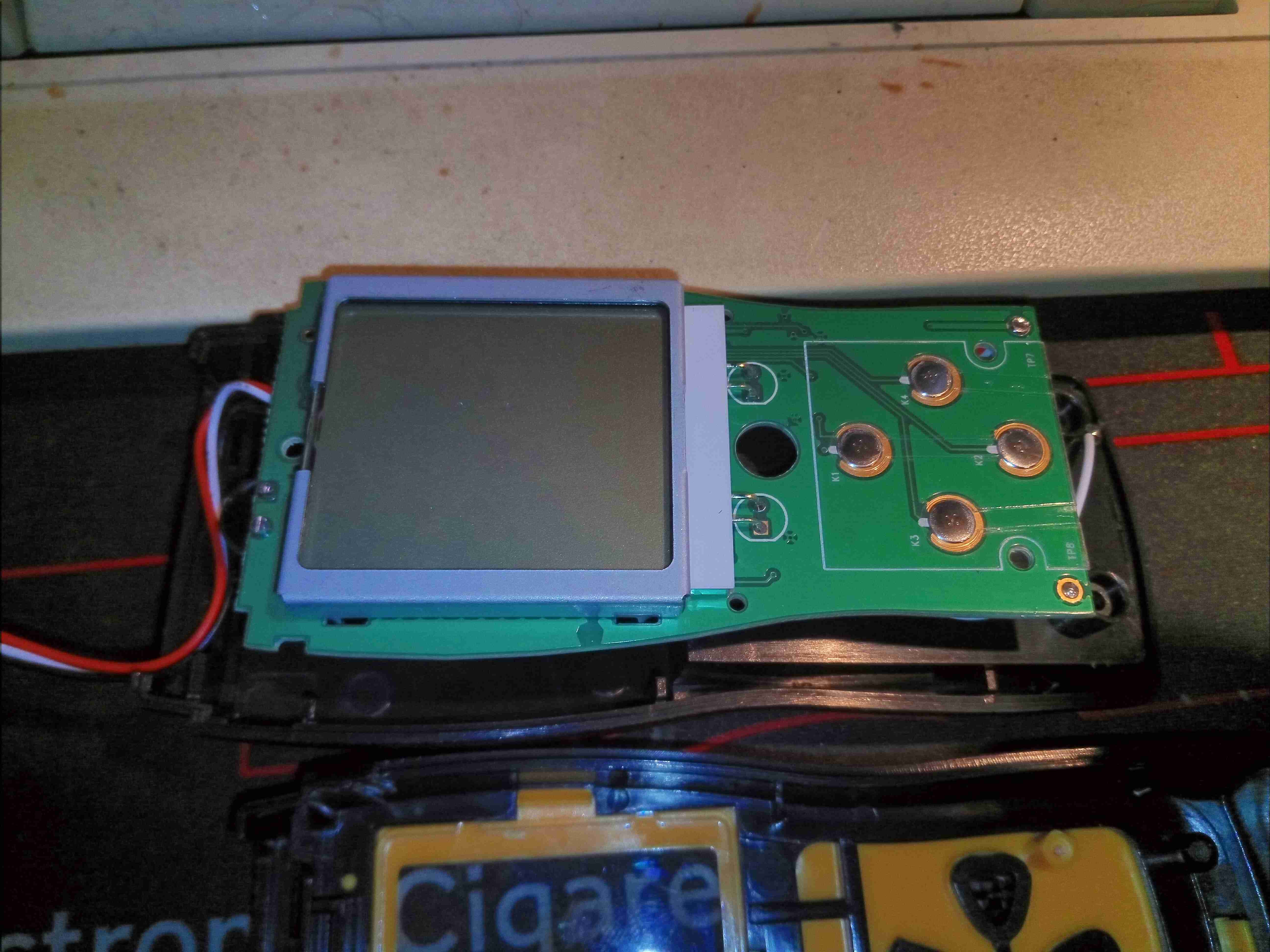
LCD
The front of the PCB has only the buttons & the LCD itself, which is backlit with a pair of green LEDs.
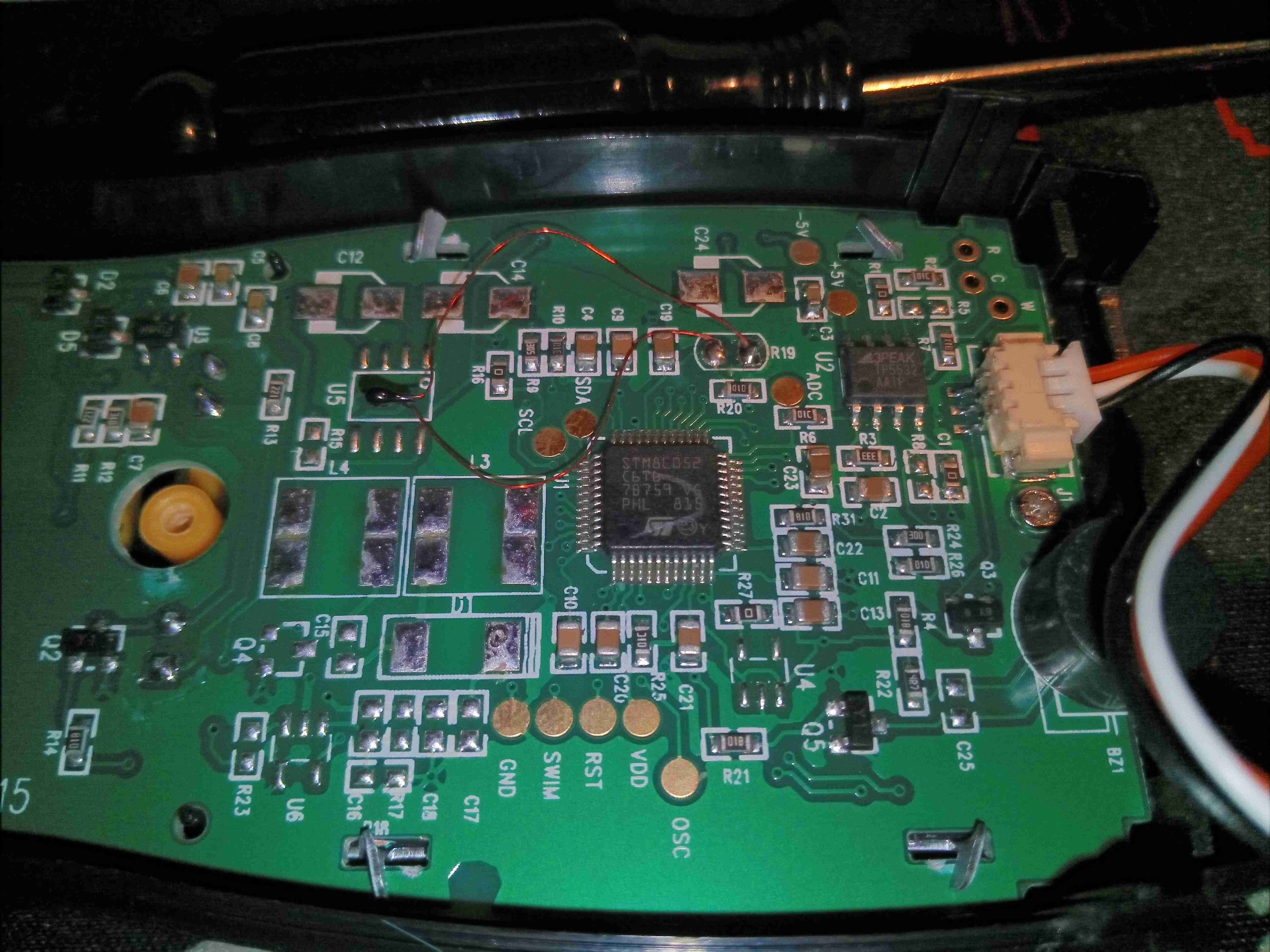
Microcontroller
There isn’t much to the actual circuitry. There’s an STM8 microcontroller, and a TP5532 zero-drift op-amp to deal with the sensor front end. Rather nicely, every single one of the test points is labelled! Handy for any hacking that needs to be done.
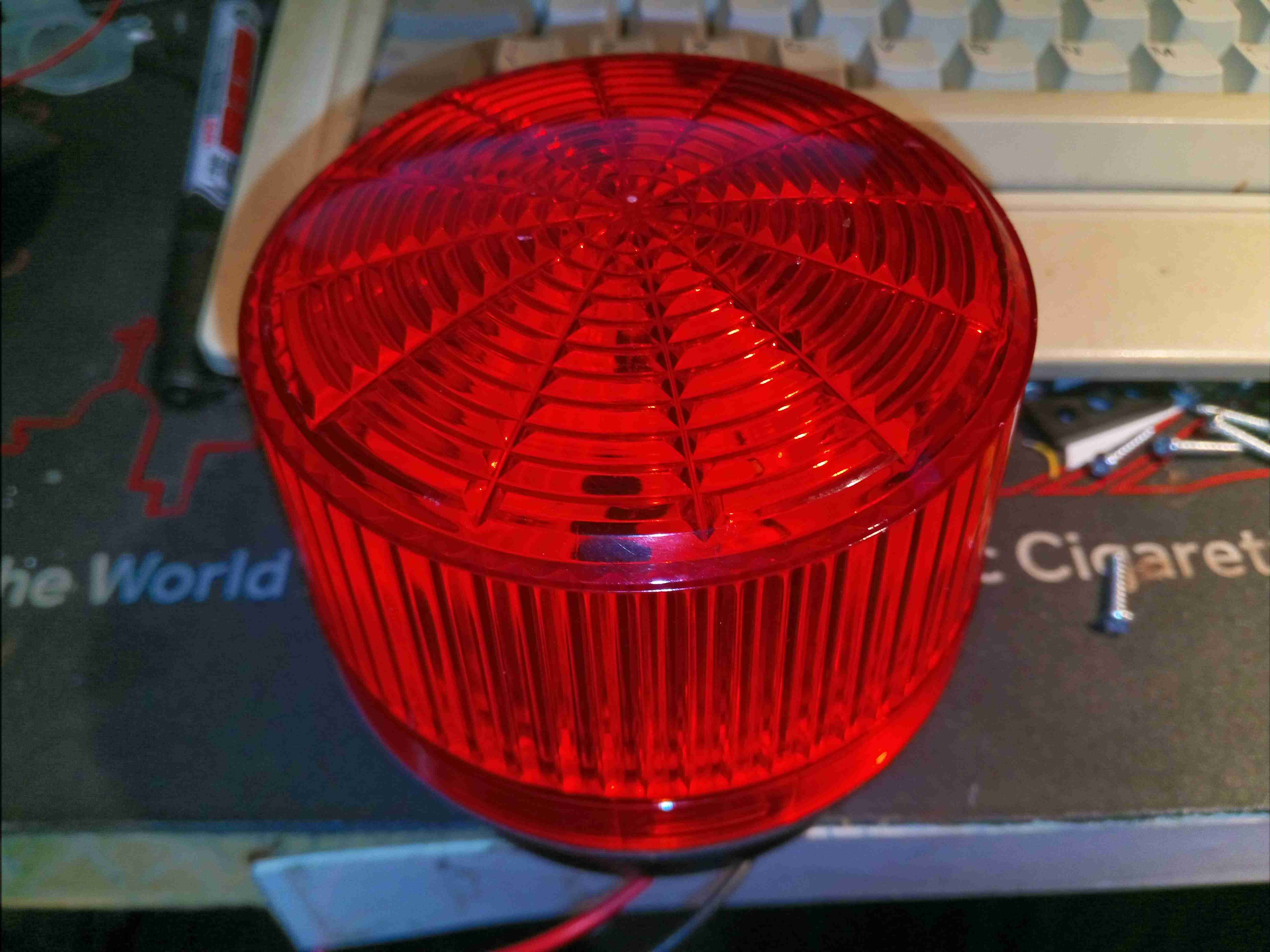
Here’s something anyone in the industrial sector will recognise – it’s a strobe beacon, which continually flashes with power applied to alert operators of a hazard. These older ones are Xenon tube based, instead of LED, so contain a bit more circuitry & some high voltages.
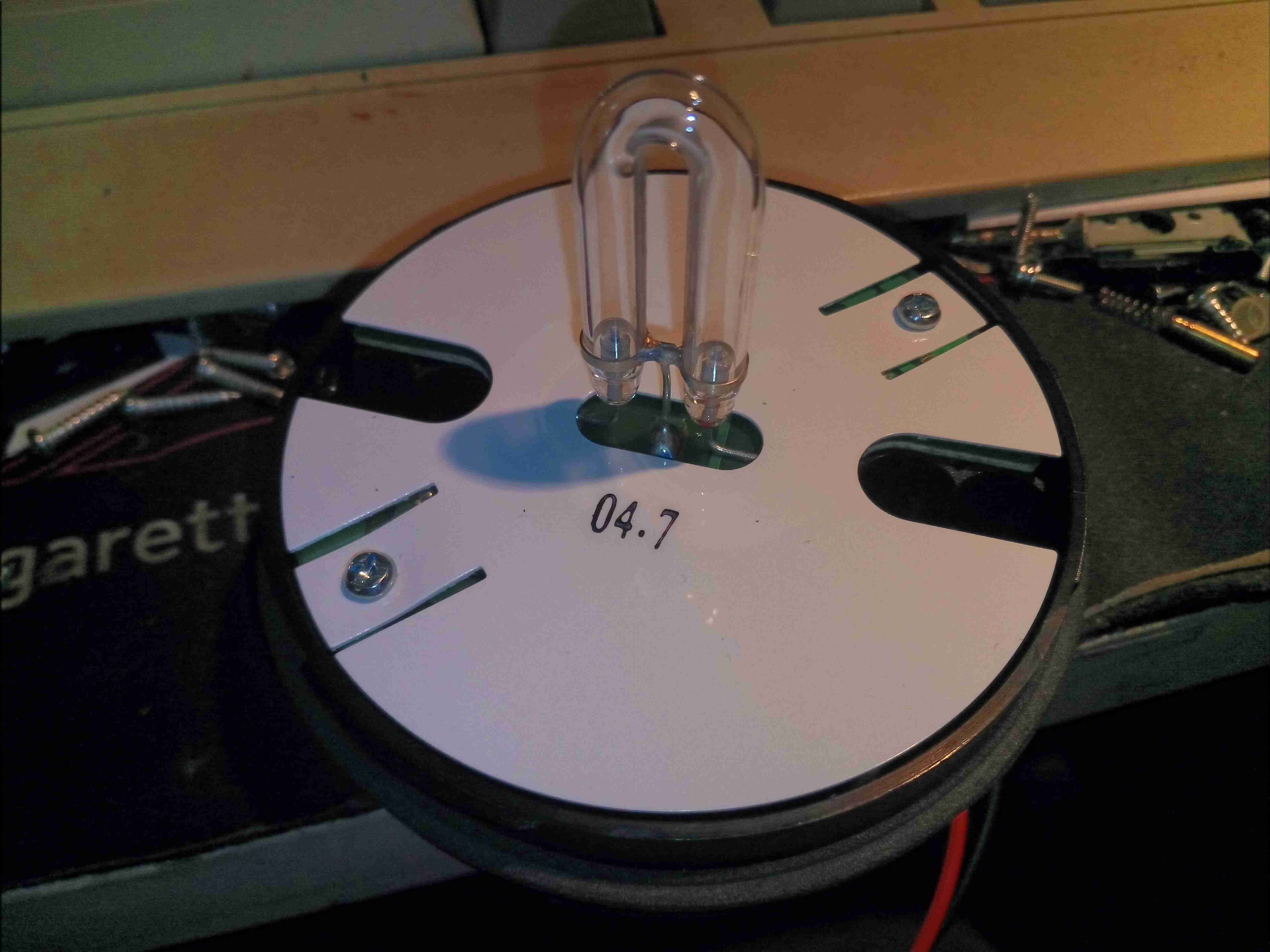
Xenon Flash Tube
Unhooking the lens reveals the Xenon lamp itself, a horseshoe format tube. A high DC potential is applied across the electrodes of the tube, below the ionisation voltage of the Xenon gas inside. When a flash is called for, a very high voltage – several kV – is applied to a 3rd trigger electrode, applied to the outside of the glass. The high electric field generated is sufficient to ionise enough gas to initiate the main discharge between the electrodes. Since the lamp is across a large capacitor, a massive current flows, generating a high-intensity flash.
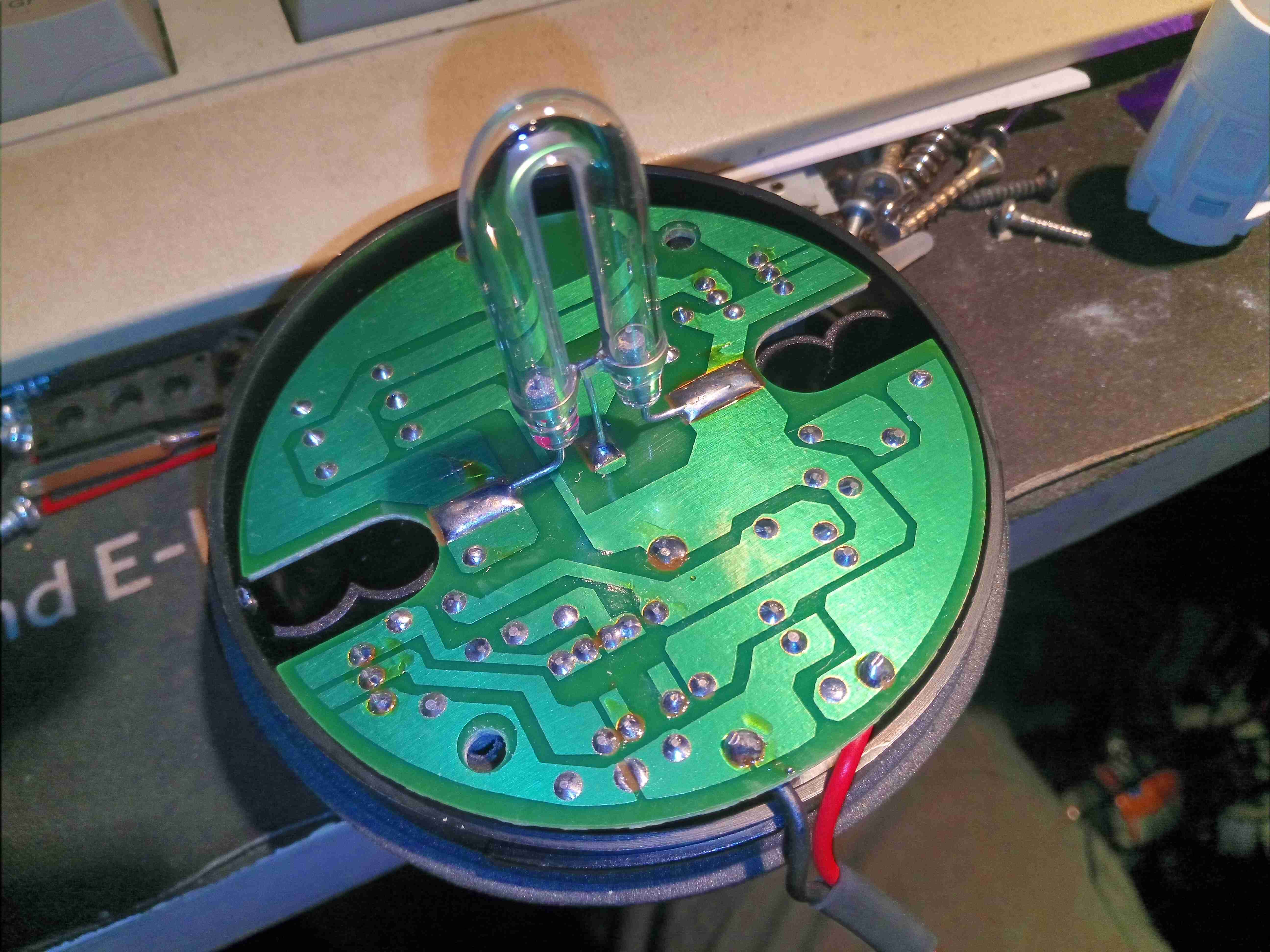
Insulator Removed
Removing the pair of screws which secure the insulator & PCB reveals the board itself, which is of cheap single-sided construction. There’s no isolation on this circuit, between the internal HV side & DC input.
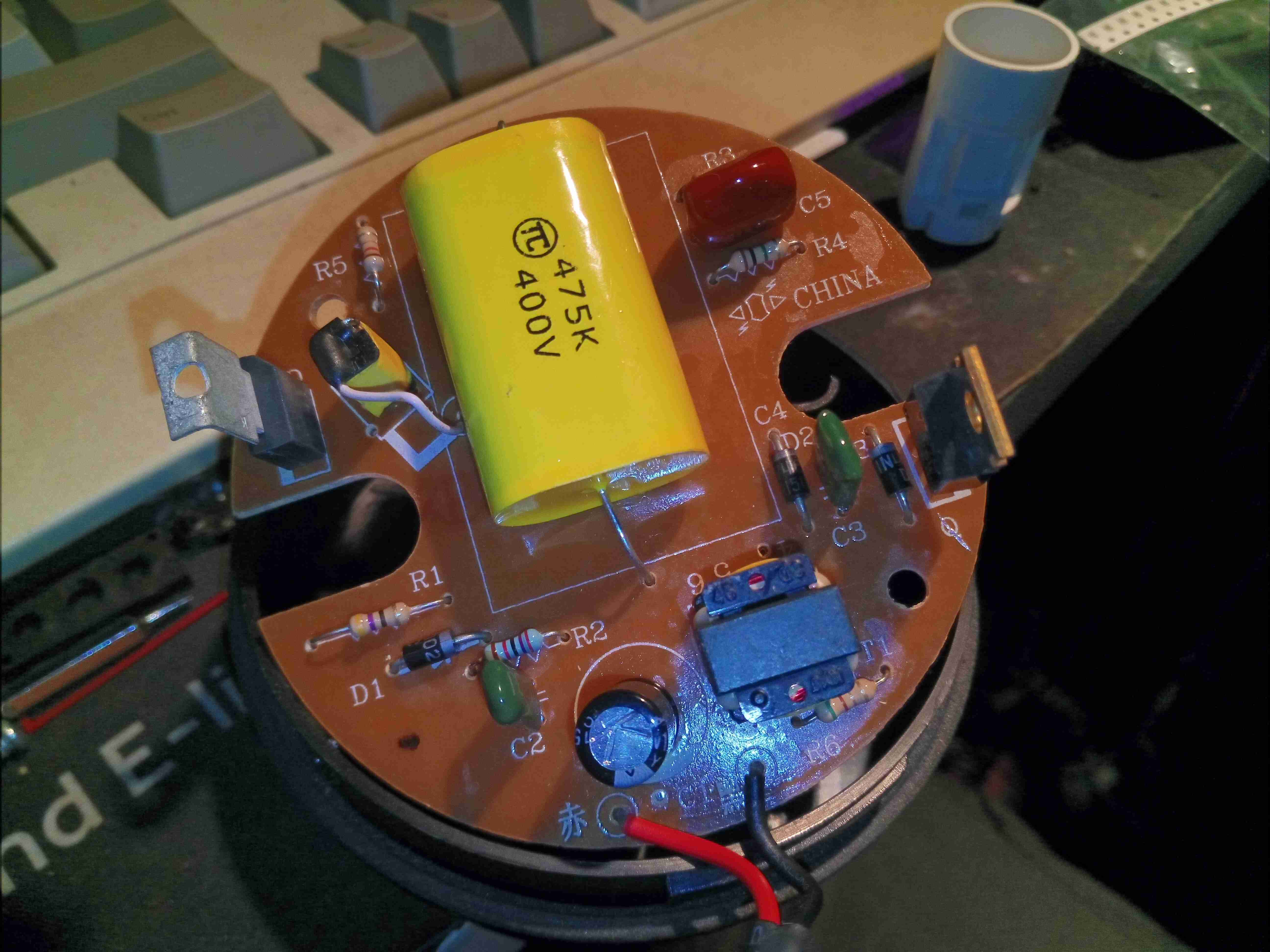
Main PCB Top
Flipping the board shows all the components. The largest part here is the main flash capacitor in the middle, a plastic film type, 4.7µF 400v. This will be charged to around 350v before the tube is triggered. Charging of the capacitor is done by the transformer at bottom right, switched by the transistor next to it. There are no ICs in this unit to control any timing of the DC-DC converter, so this is probably based around a blocking oscillator. A smaller capacitor to the top right of the main flash cap is part of the trigger circuit, which is charged through a resistor from the main HV supply. When the voltage on this capacitor reaches a high enough level, the large SCR on the left side of the board switches on, dumping the charge on that capacitor through the trigger transformer, the small yellow device with the white wire. This small transformer generates the high voltage pulse to trigger the flash lamp.
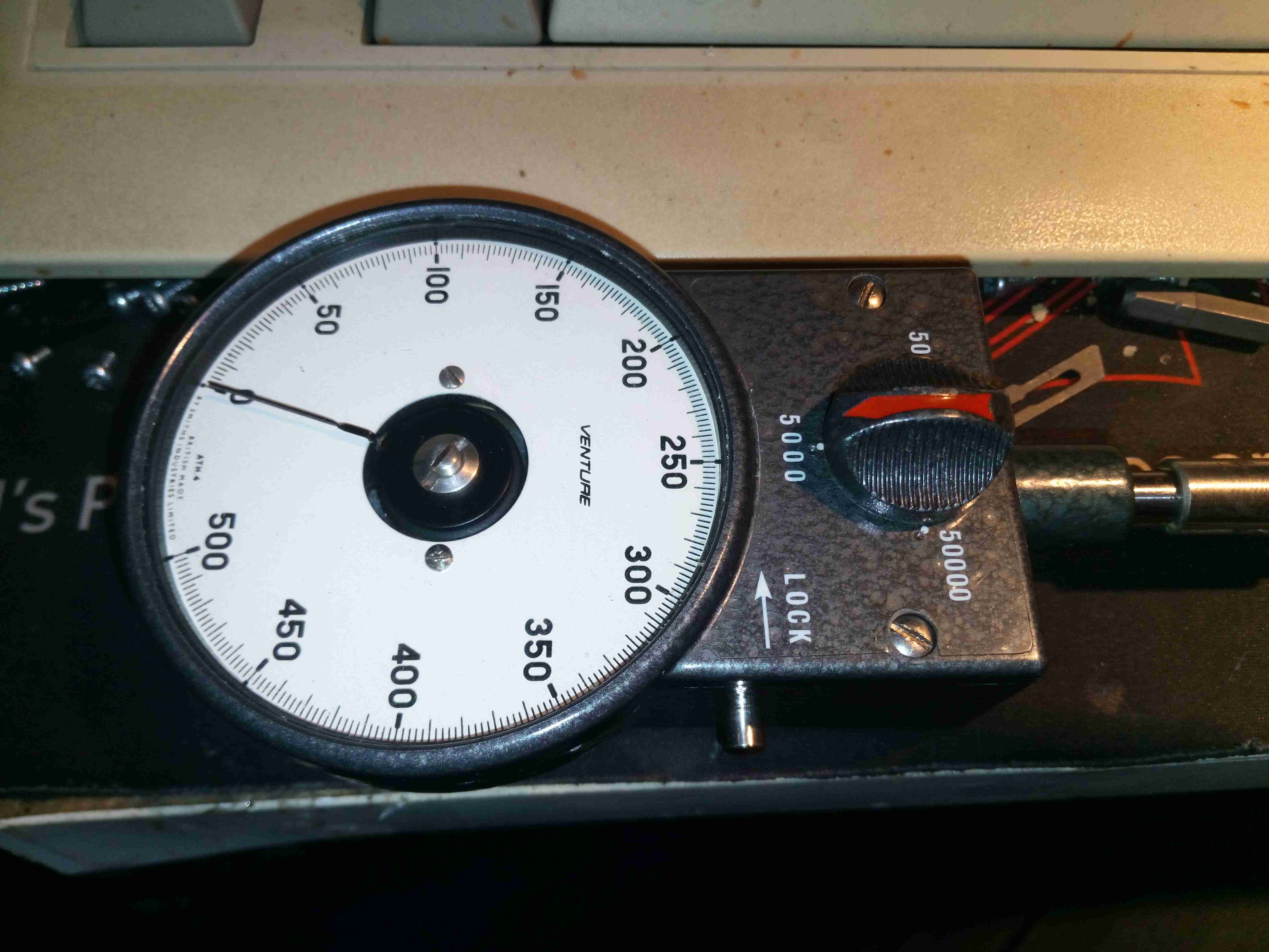
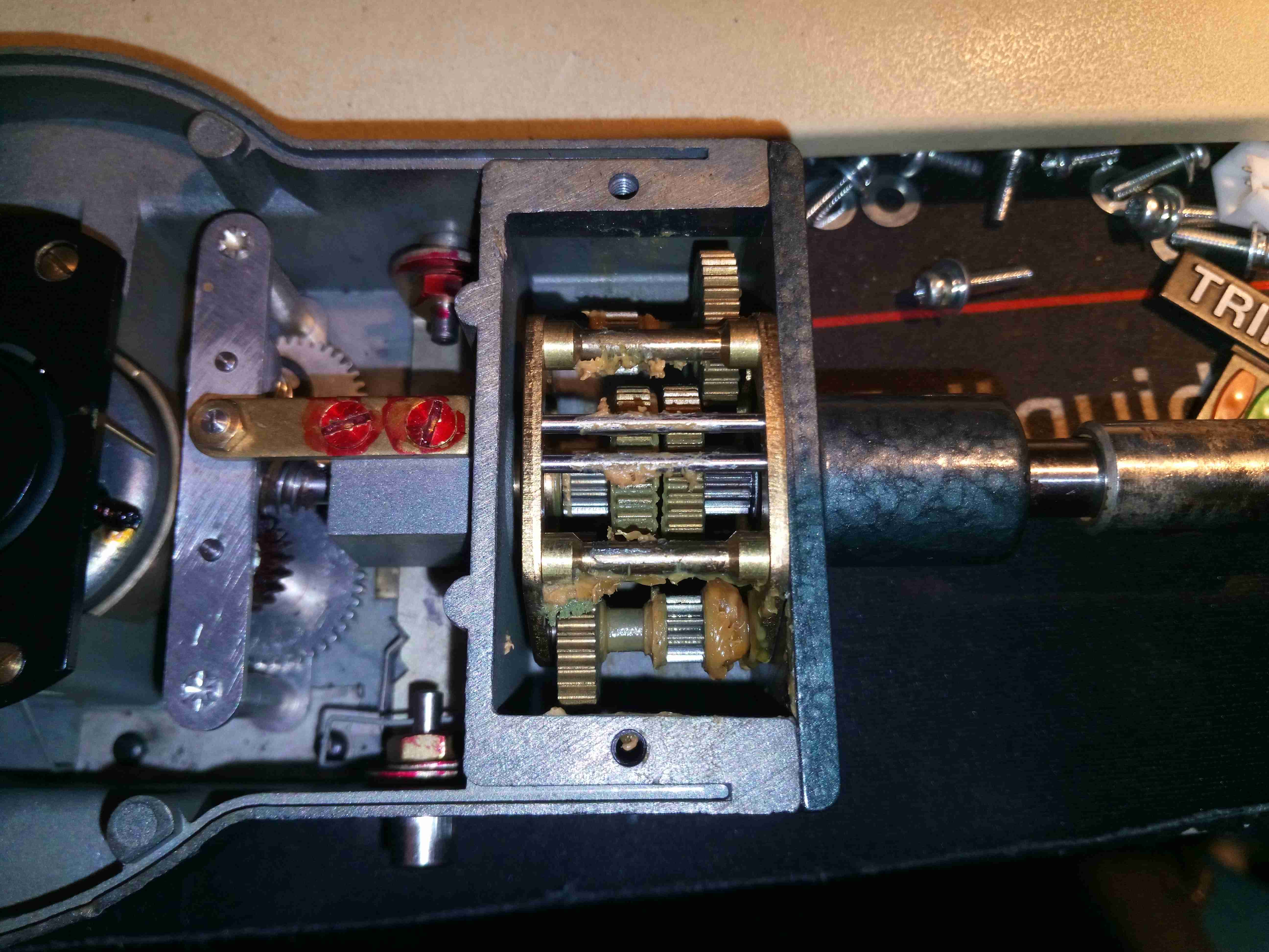
Quite a nice skip find this – it’s a mechanical tachometer from Smiths, the Venture ATH4. Scaled to run to 50,000RPM in x1, x100 & x1000 scales this is quite a nice instrument. Input drive shaft is on the right, with the scale selection knob & pointer lock. Mechanical eddy-current movement is on the left.
Top Cover Removed
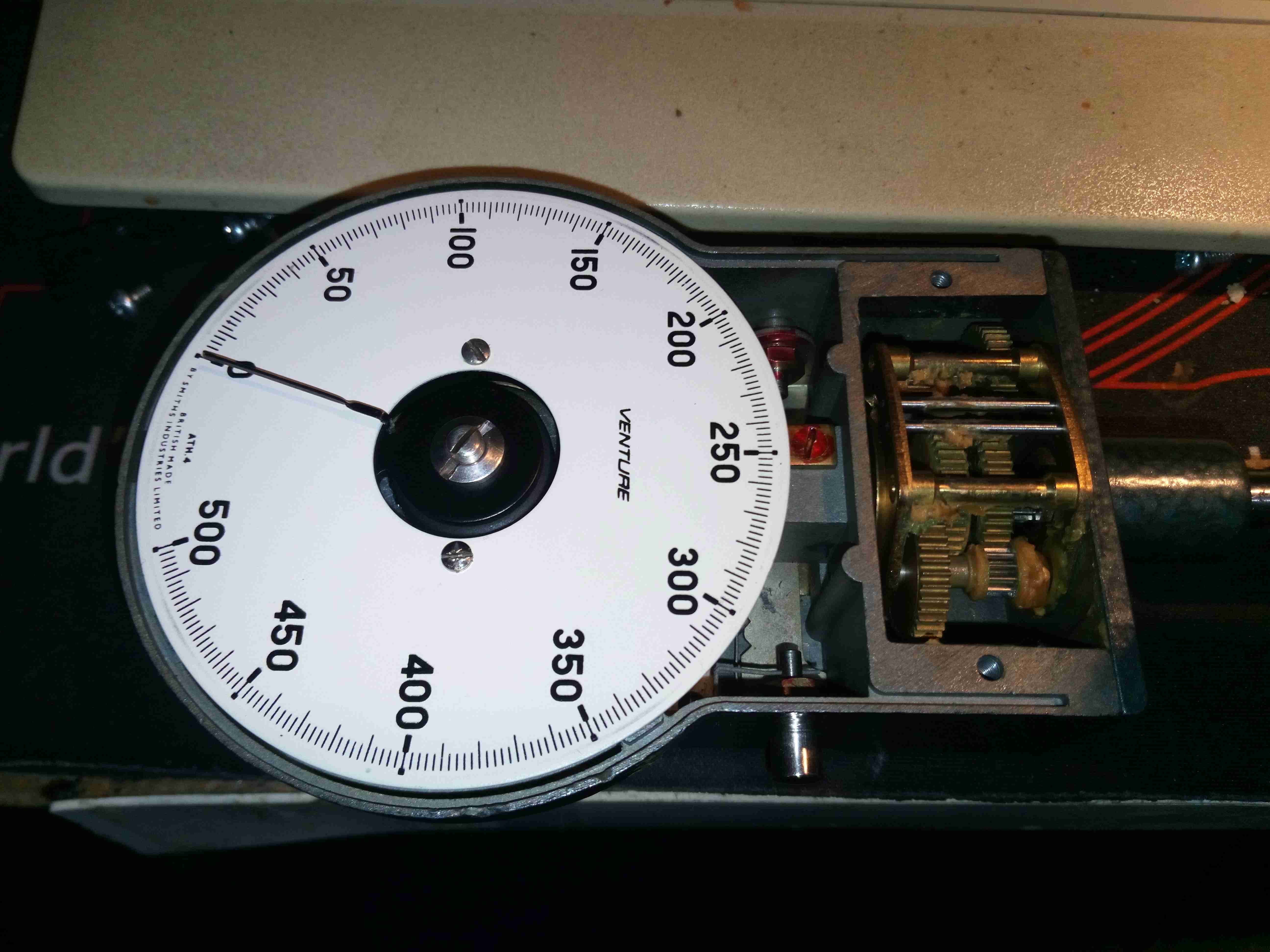
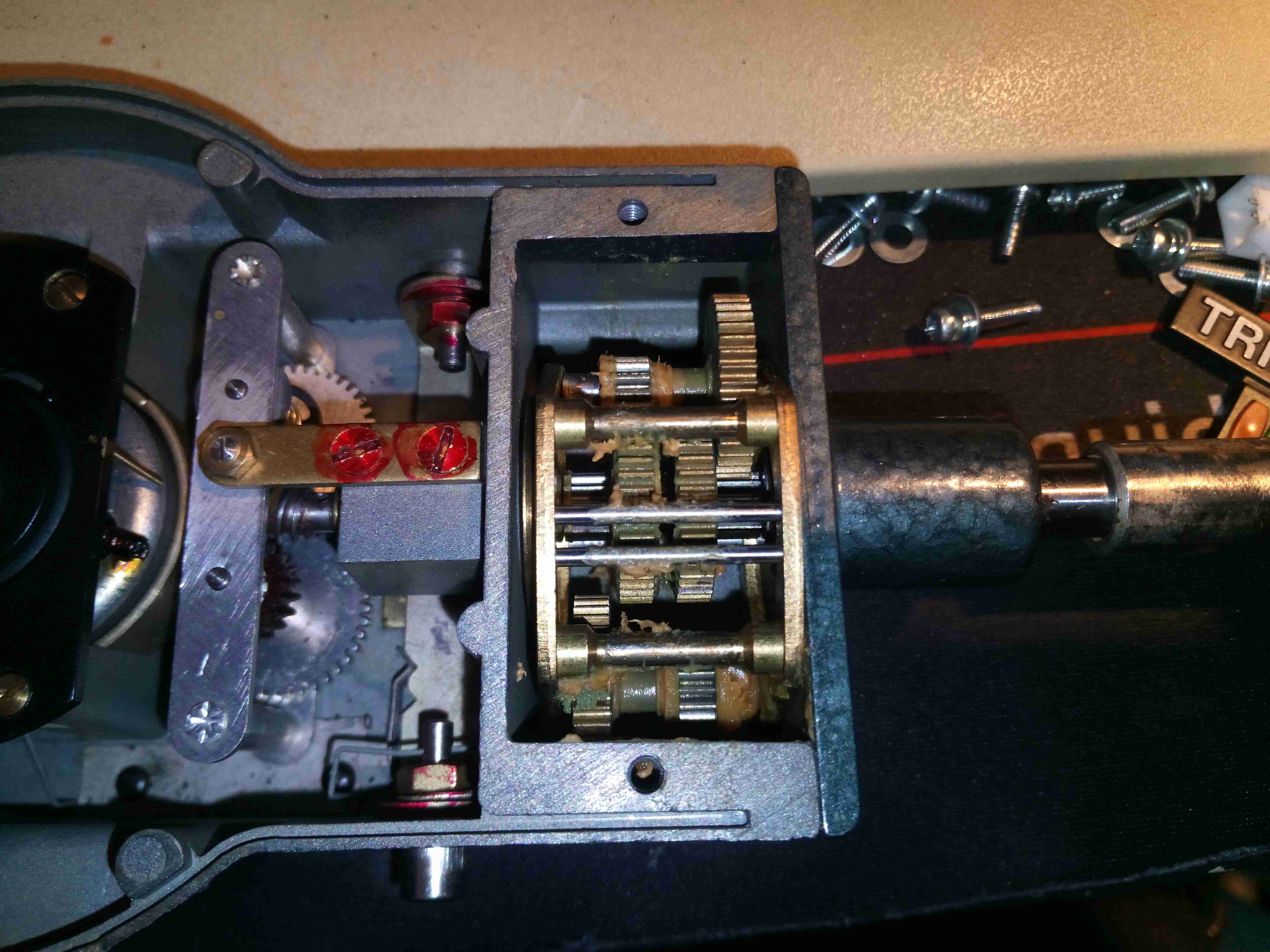
3 small screws allow the front cover with the crystal to be removed from the movement. Calibration is done with the adjustment in the centre of the movement itself, which will alter the tension on the hairspring. The ranging gearbox is on the right side, full of old hardened grease which I’ll probably clean out & replace with fresh.
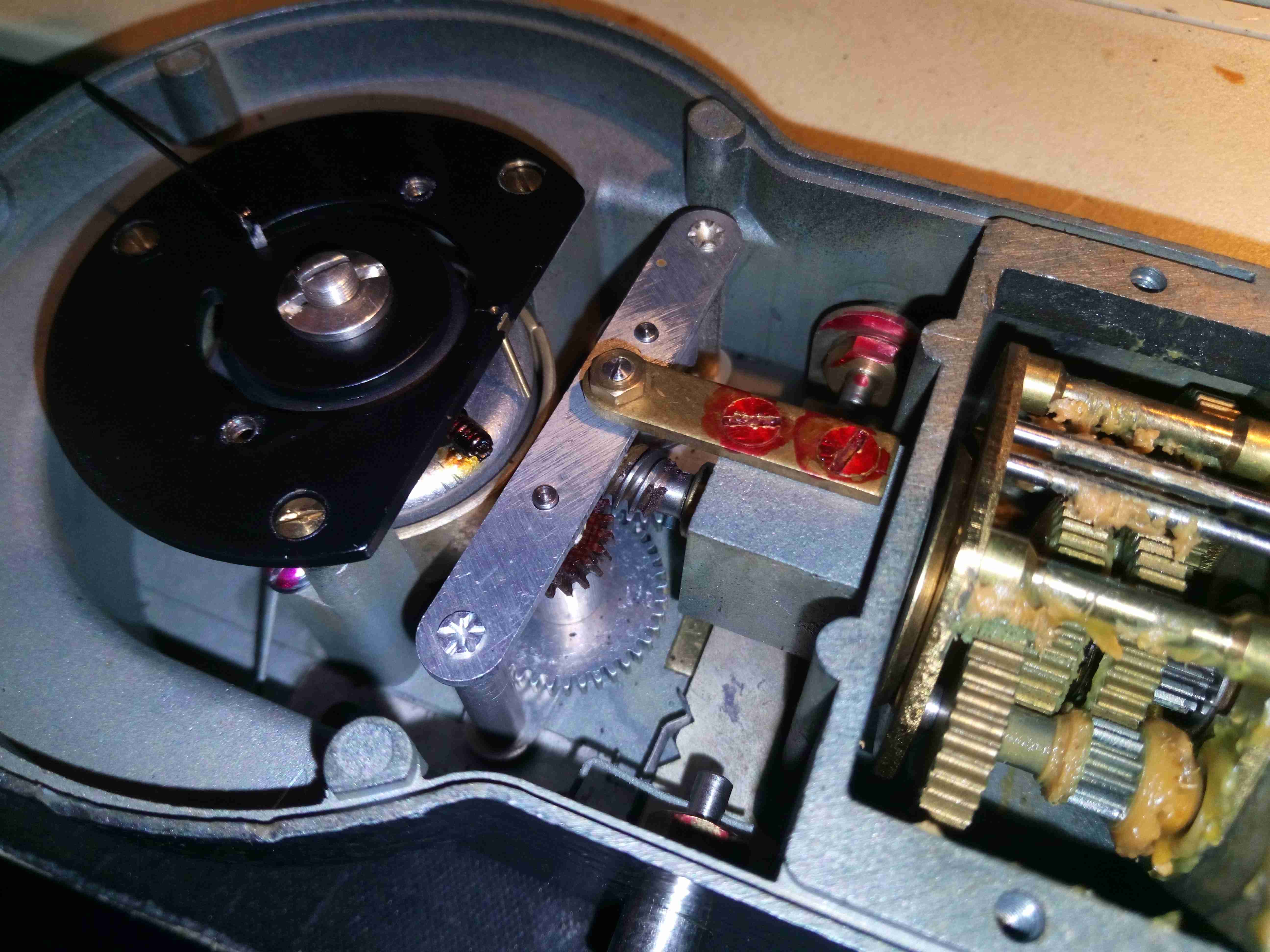
Bare Mech
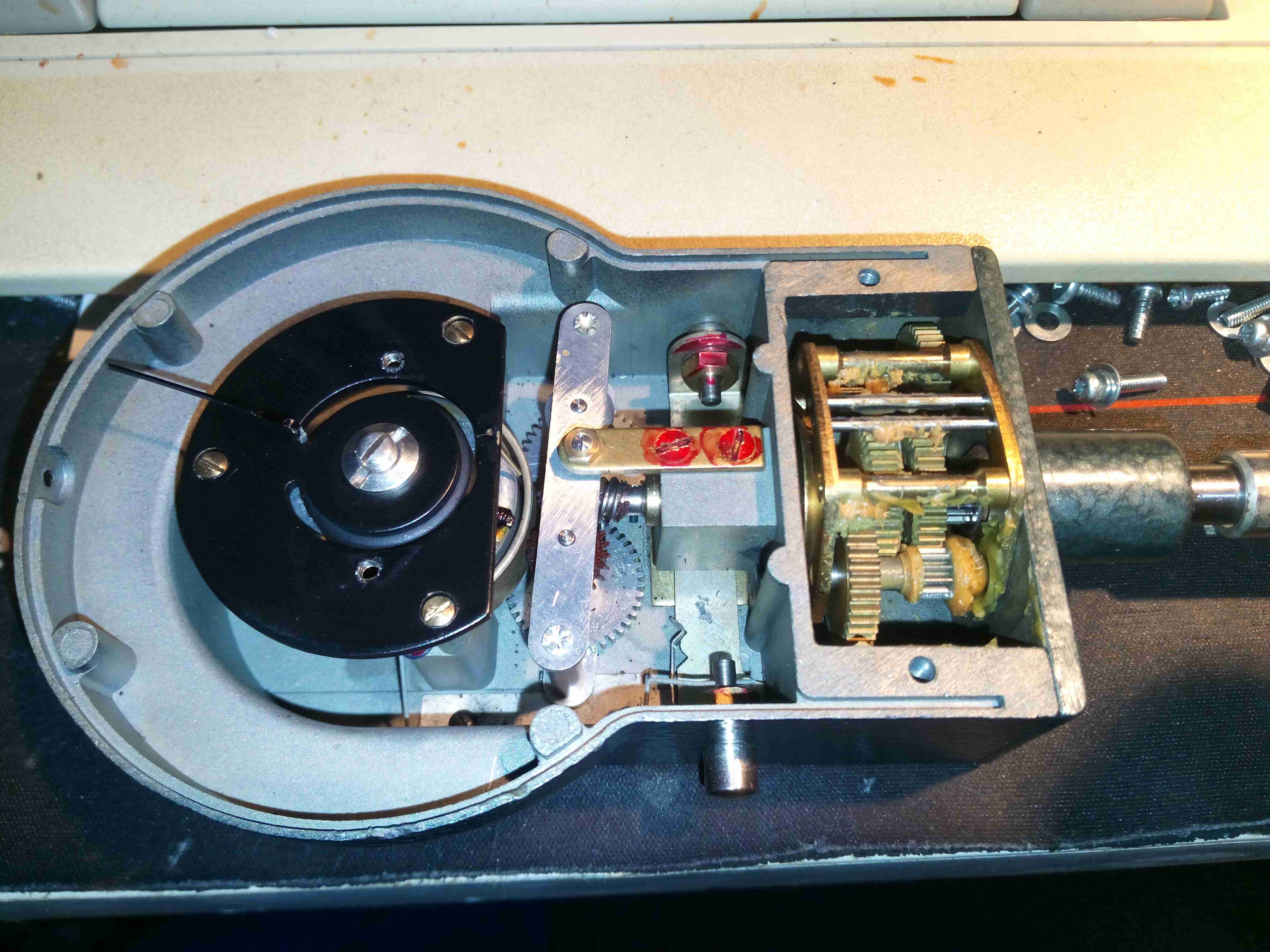
With care it’s possible to remove the scale face without harming the movement or the very fine needle, this shows the remaining part of the mechanical drive. The see-saw after the gearbox is the reversing drive, so that the needle moves regardless of the input shaft rotational direction.
Low Gear
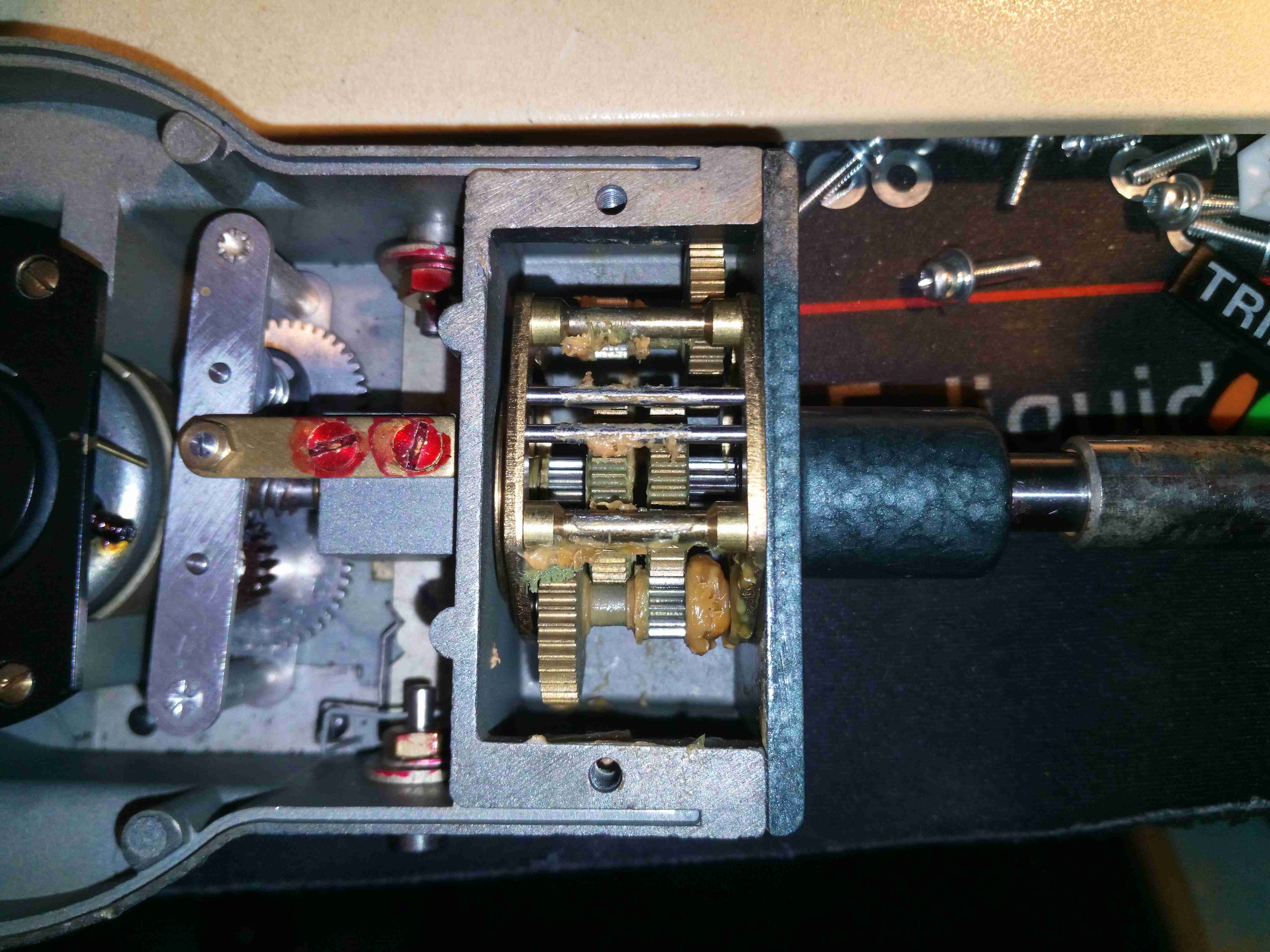
The ranging gearbox is very neat. It has 3 different gear ratios for the different ranges – here it is in the 500RPM position, which effectively gears the input drive up to drive the movement faster.
Mid Range
On the mid scale of 5000RPM, the gearbox reverts to direct drive into the movement, by pushing the input & output gears together – they both have gods on their faces to facilitate this drive.
High Gear
On the 50,000RPM range, the gearing changes to a reduction drive, slowing down the output to the movement.
Movement Drive
After the ranging gearbox, there’s a final worm-drive reduction, with a fibre gear to reduce friction, and the reversing drive. The alloy bar swings with the forces of the worm drive to keep the drive to the eddy current movement, which is just visible under the black plate, running in the same direction regardless of direction of input drive. The pointer lock is also visible here, as the fine wire under the black plate. This just touches the drag cup to stop the pointer moving.
Amazingly, even though the calibration sticker has this instrument as last calibrated in 1997, it seems to be still perfectly within calibration – I’ll have to compare with a laser tachometer to see how accurate it actually is.
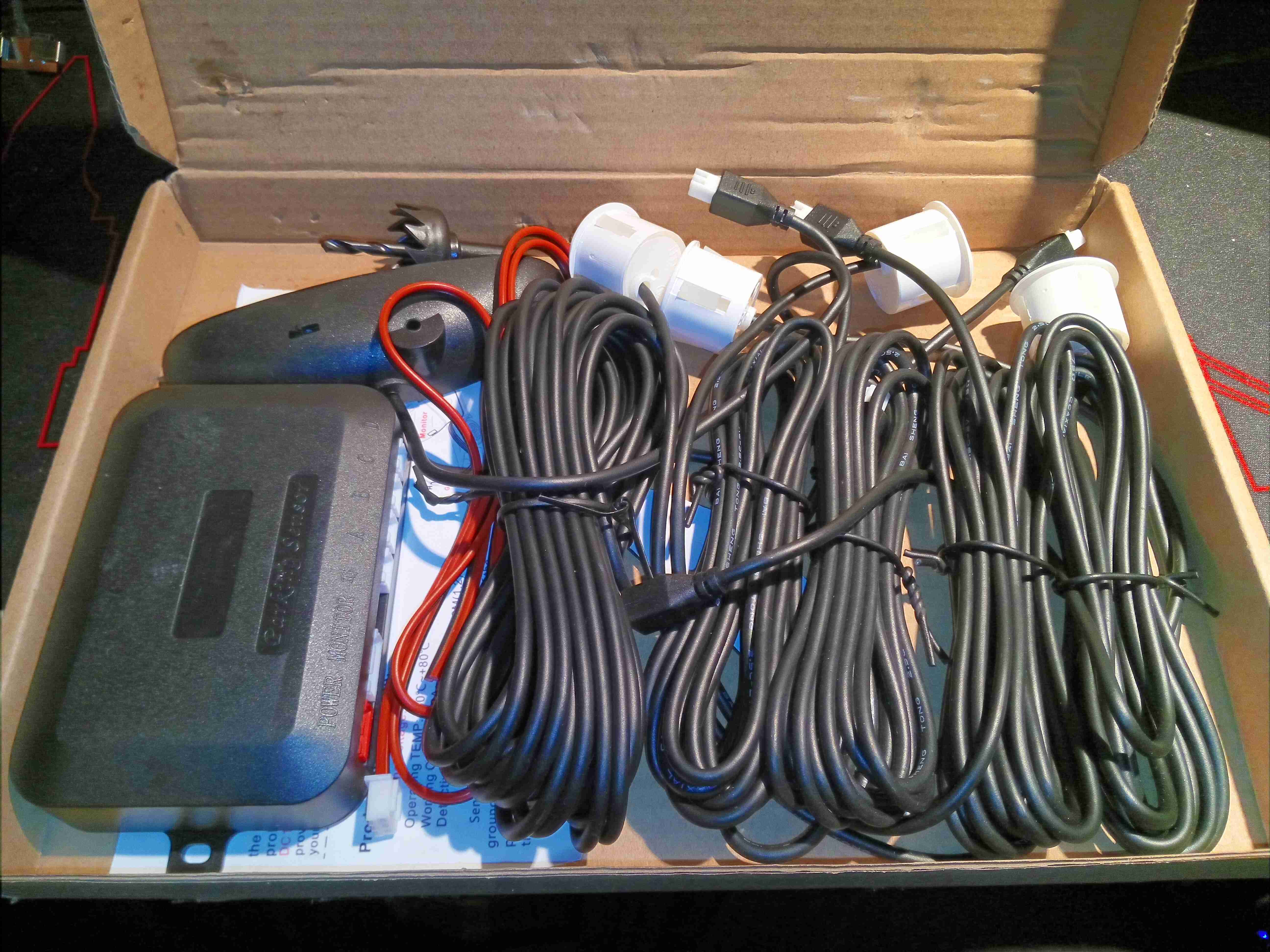
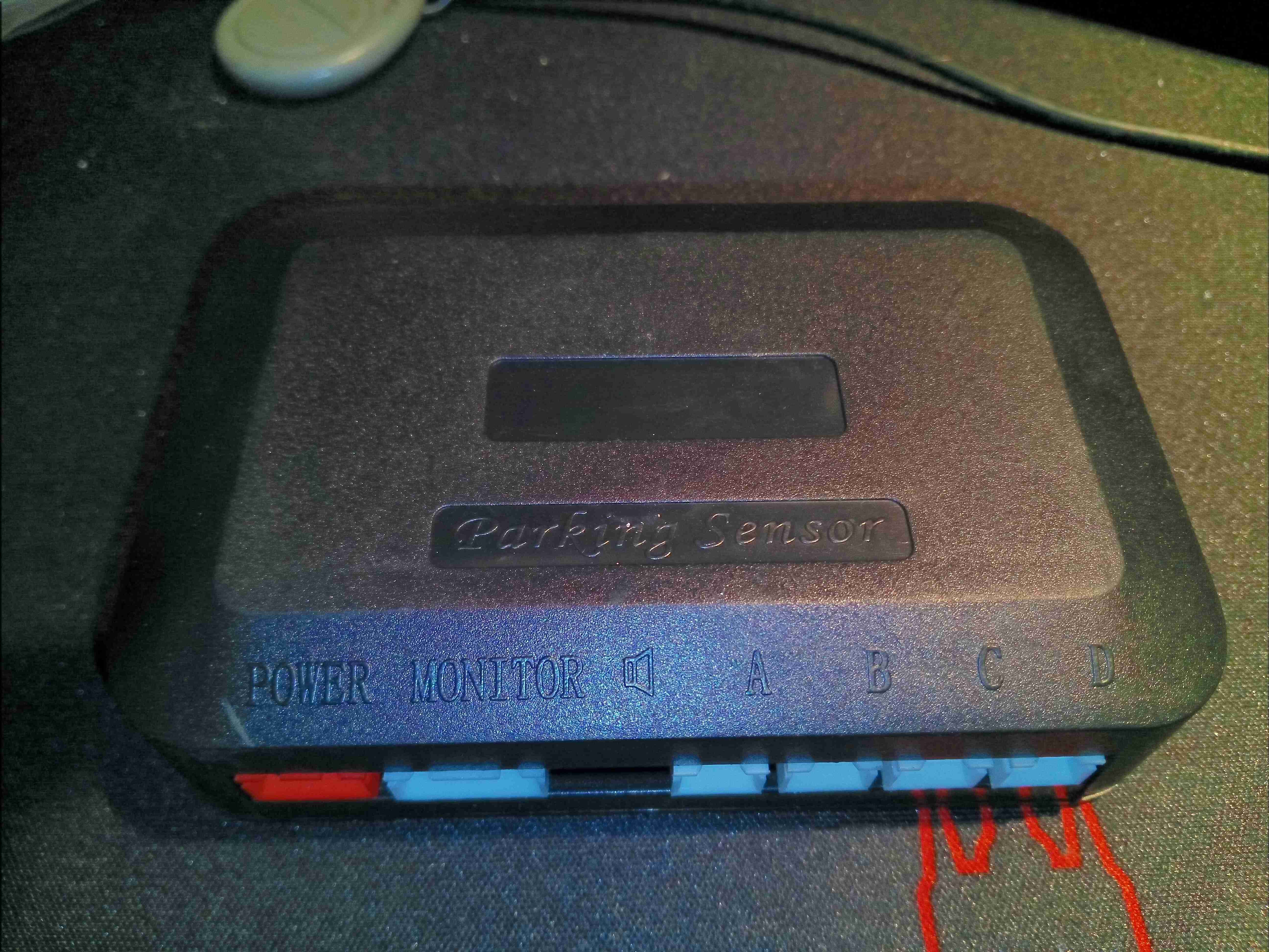
This is a cheap kit from eBay, to retrofit an older car with ultrasonic parking sensors. 4 sensors are included in the kit, along with a hole saw to fit them to the bumper. There’s a small controller module, and a display module that fits onto the dash of the car.
Controller Module
Here’s the controller module, with it’s row of connectors along the front. The unit gets it’s power from the reversing light circuit, via the red connector.
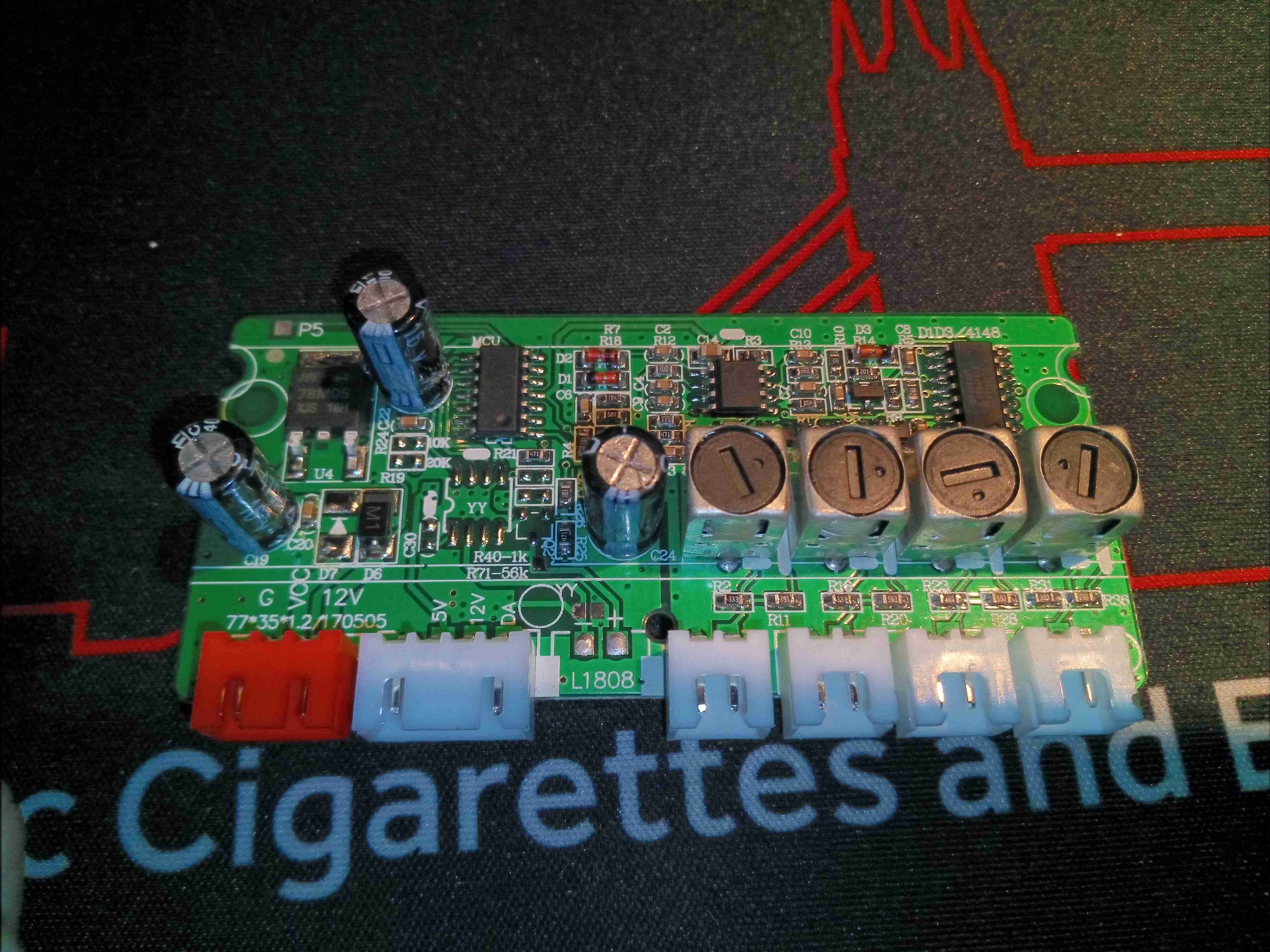
Main Controller PCB
Removing a couple of screws allows the PCB to be removed. There’s quite a bit on this board, including 4 tunable inductors for the ultrasonic transducers. There’s a linear voltage regulator on the left which supplies power to the electronics, and a completely unmarked microcontroller.
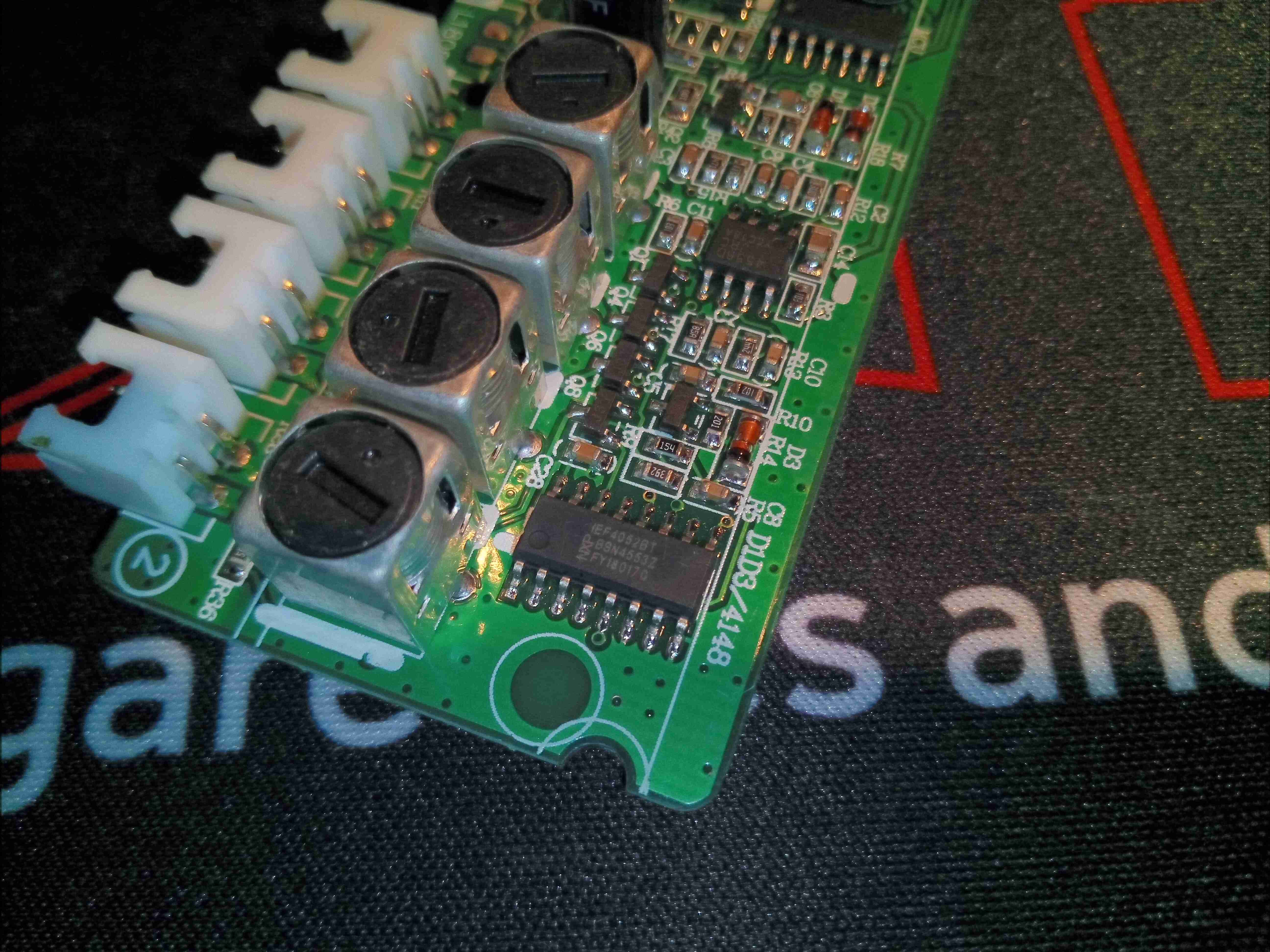
Electronics Closeup
A closer look at the analogue end of the board shows a JRC4558D dual Op-Amp, and an NXP HEF4052B analogue multiplexer. As the microcontroller is unmarked I have no data for that one.
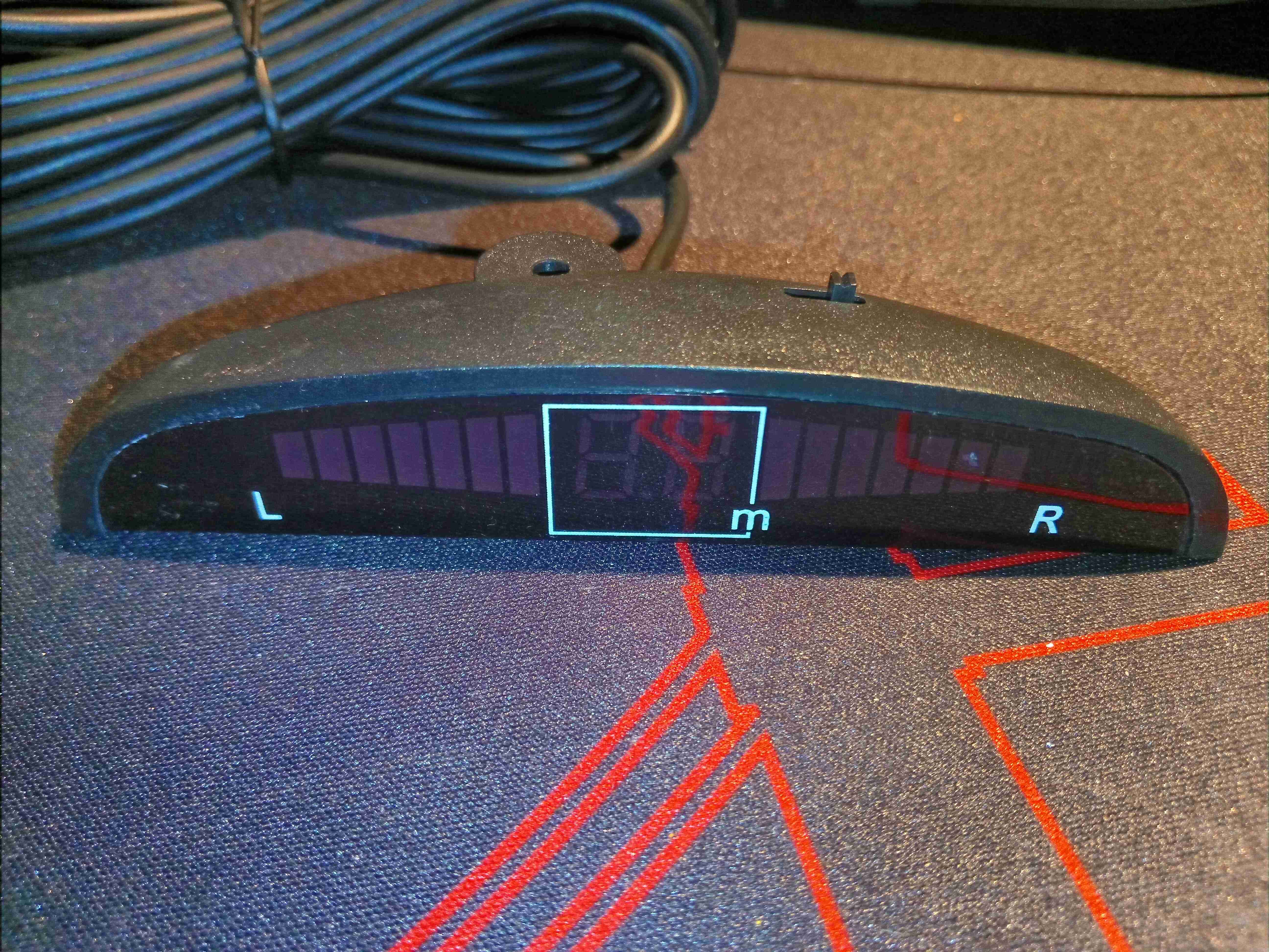
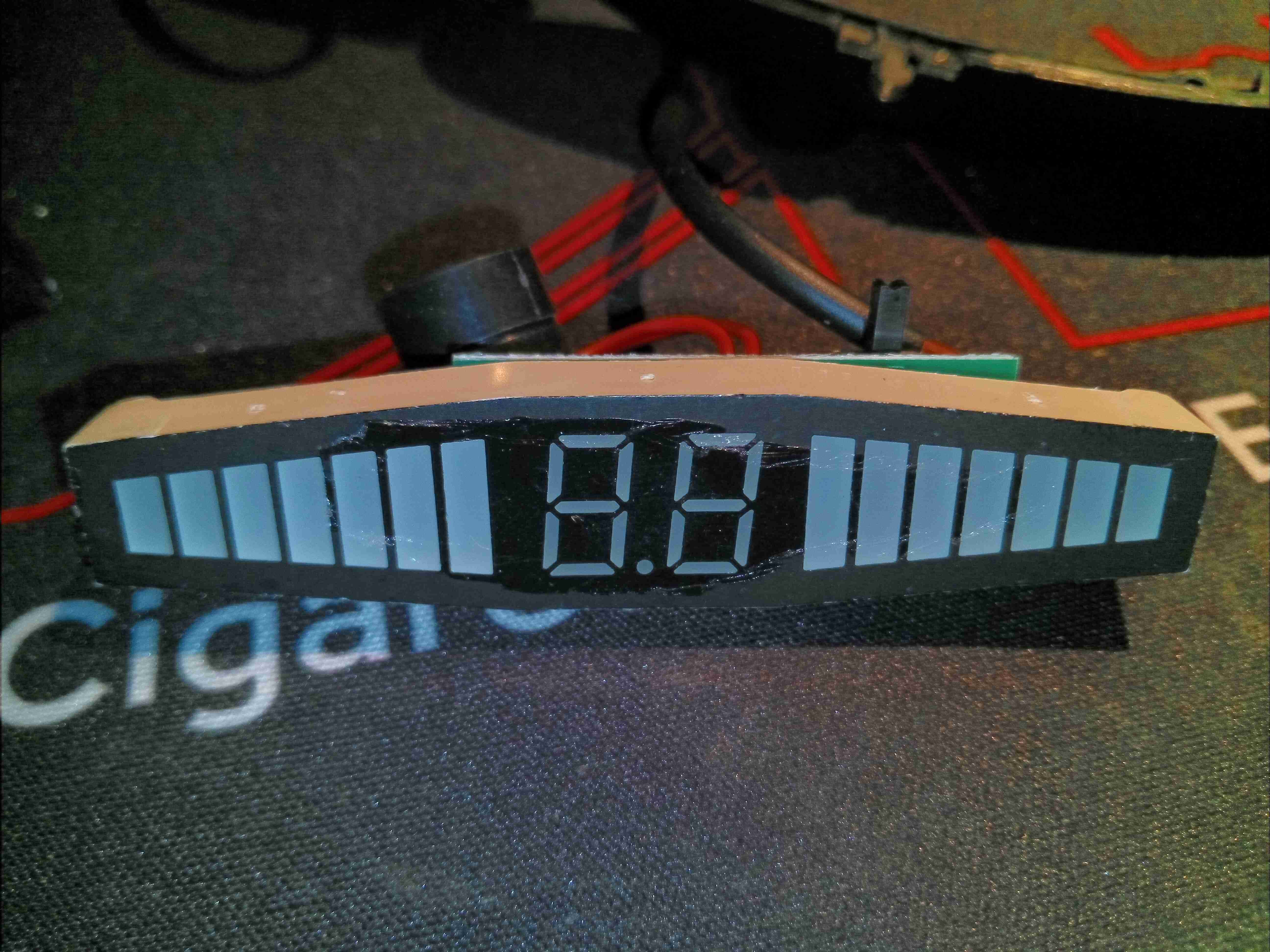
Dash Display
The dash display is housed in another small plastic box, with bargraphs for each side of the car & an overall distance meter.
Display Module
Clearly this is a custom module, with the tapered bargraph LEDs on each side & the 7-segment display in the centre. There’s a beeper which works like every factory-fitted unit does, increasing in rate as the distance closes.
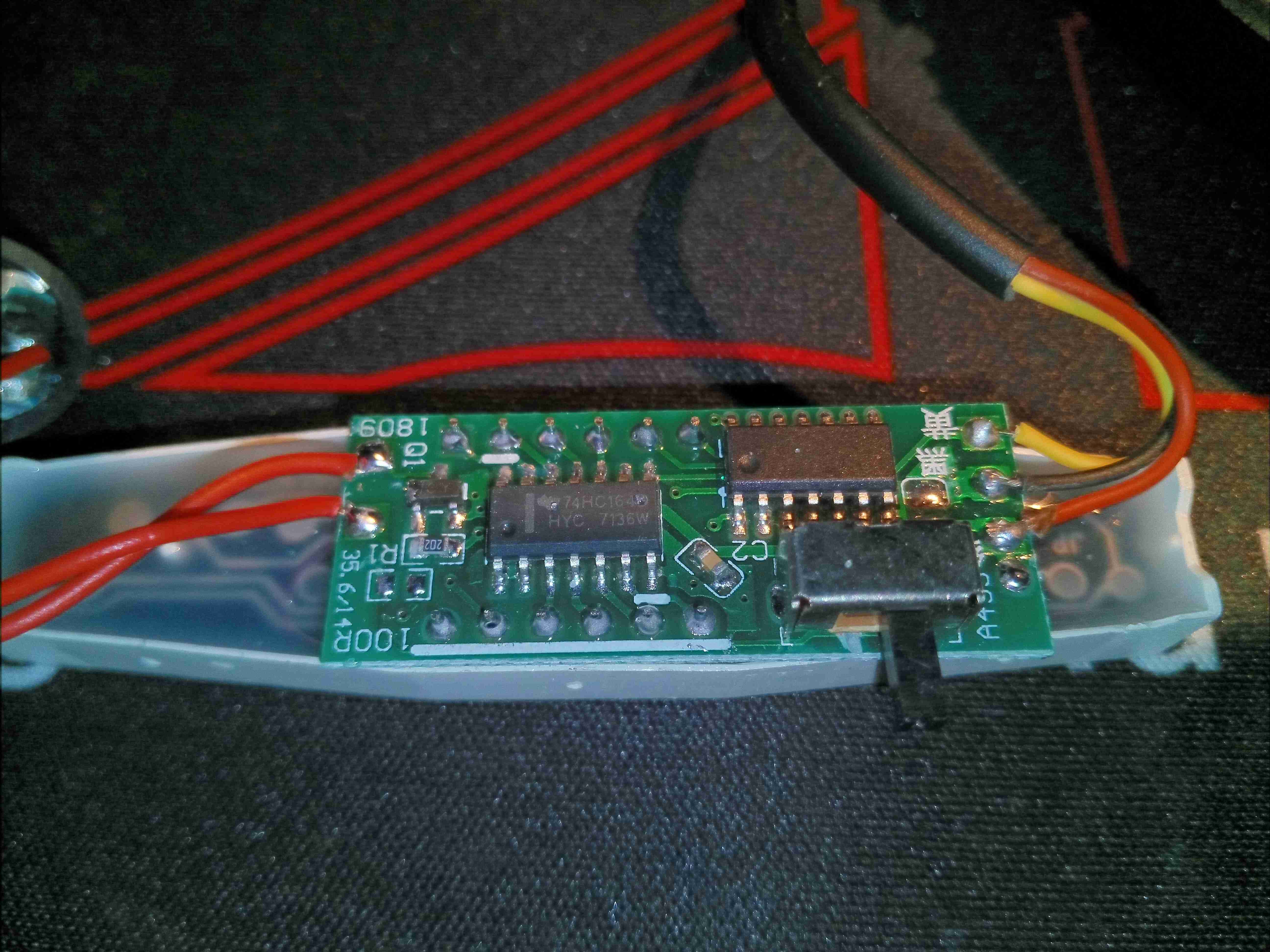
Display PCB
The back of the display module has the driver PCB, with yet another unmarked microcontroller, and a TI 74HC164 serial shift register as a display driver. There’s only 3 wires in the loom from the controller, so some sort of 1-wire protocol must be being used, while I²C is the most likely protocol to be talking to the display driver circuit. There’s also a small switch for muting the beeper.
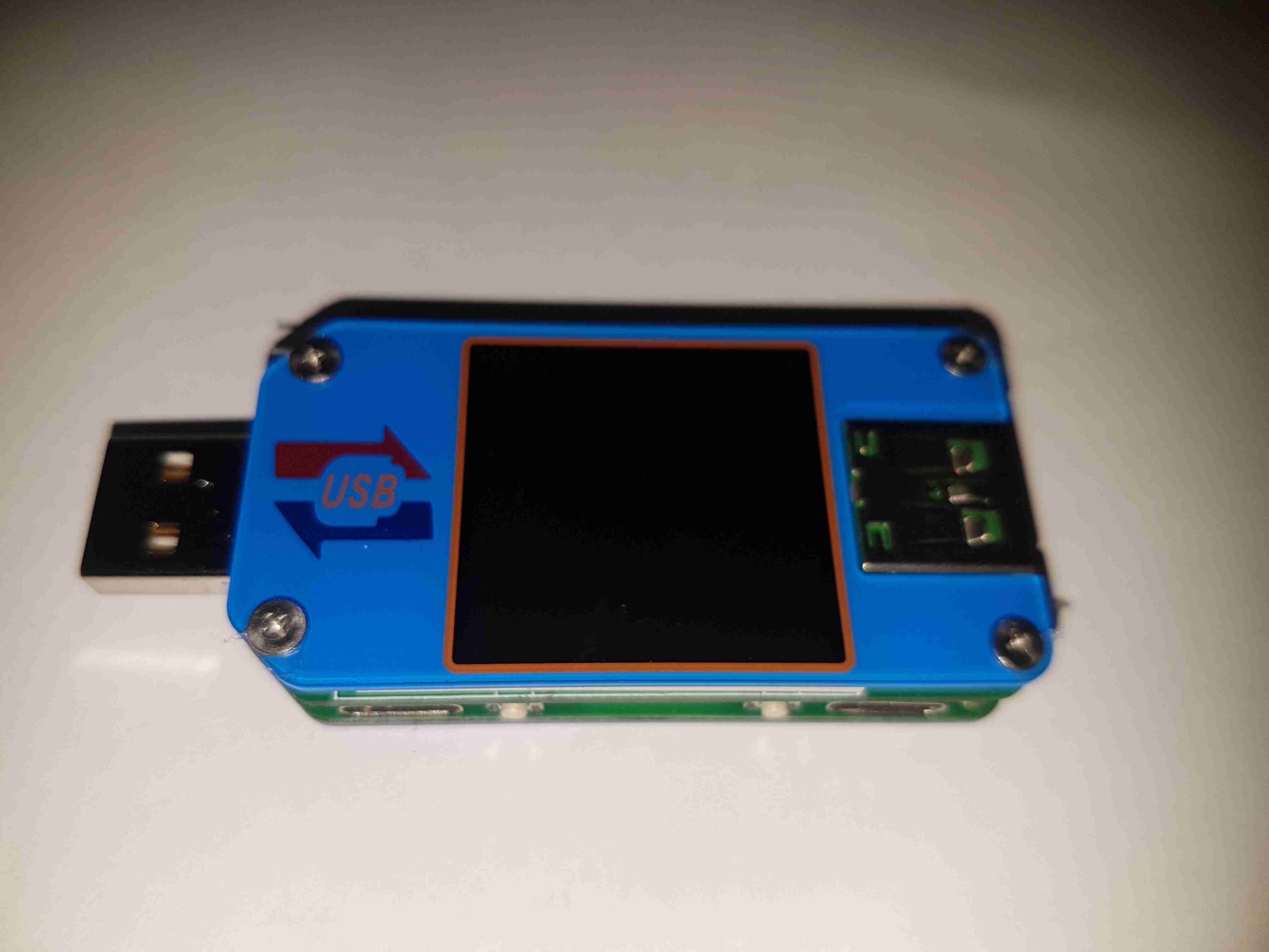
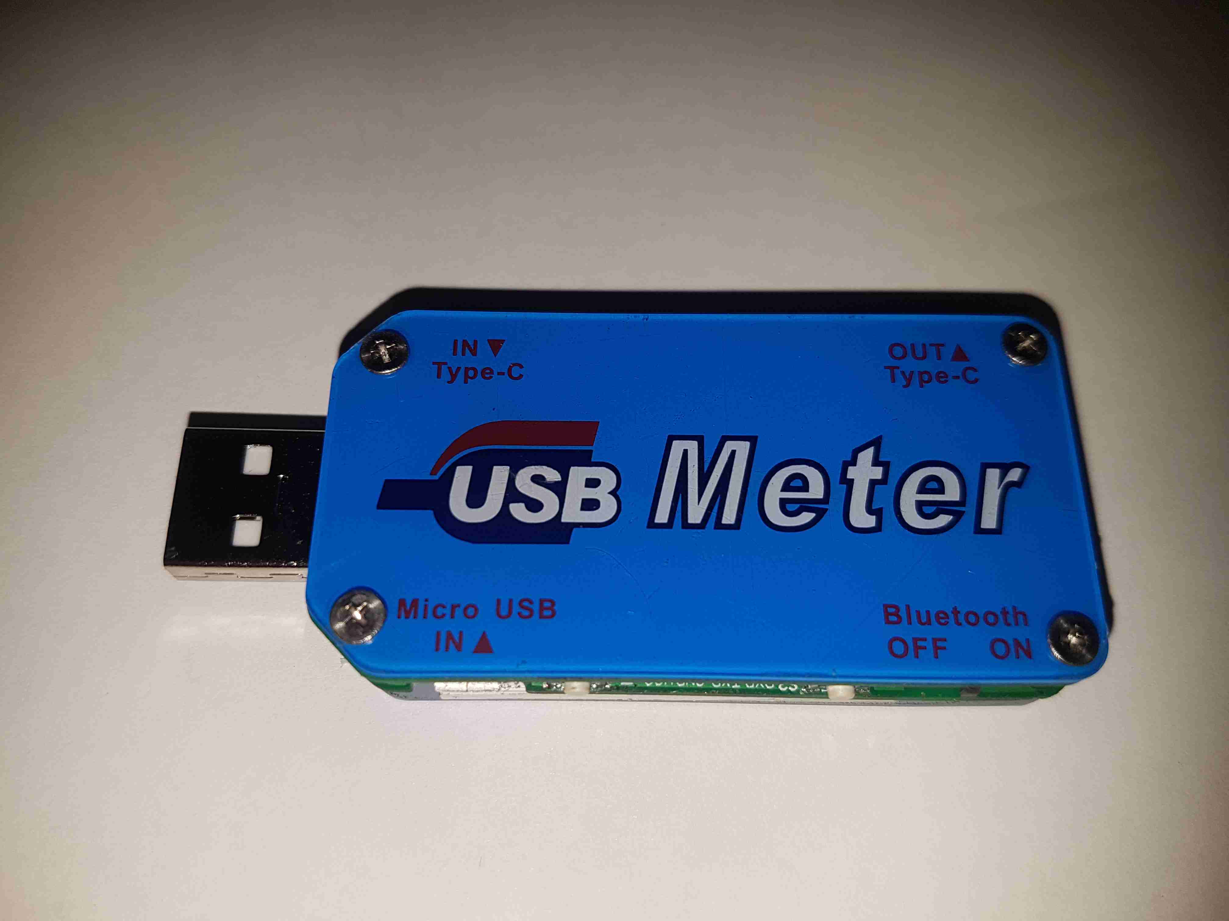
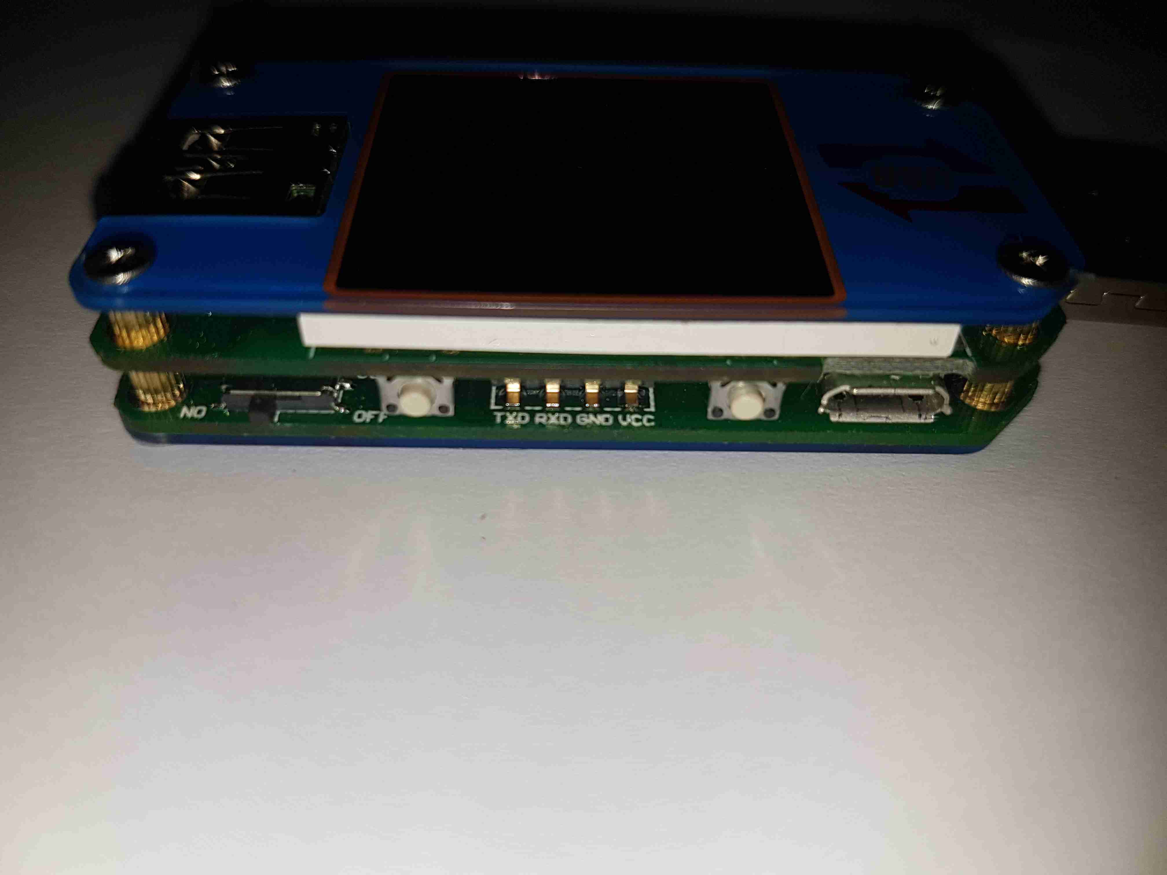
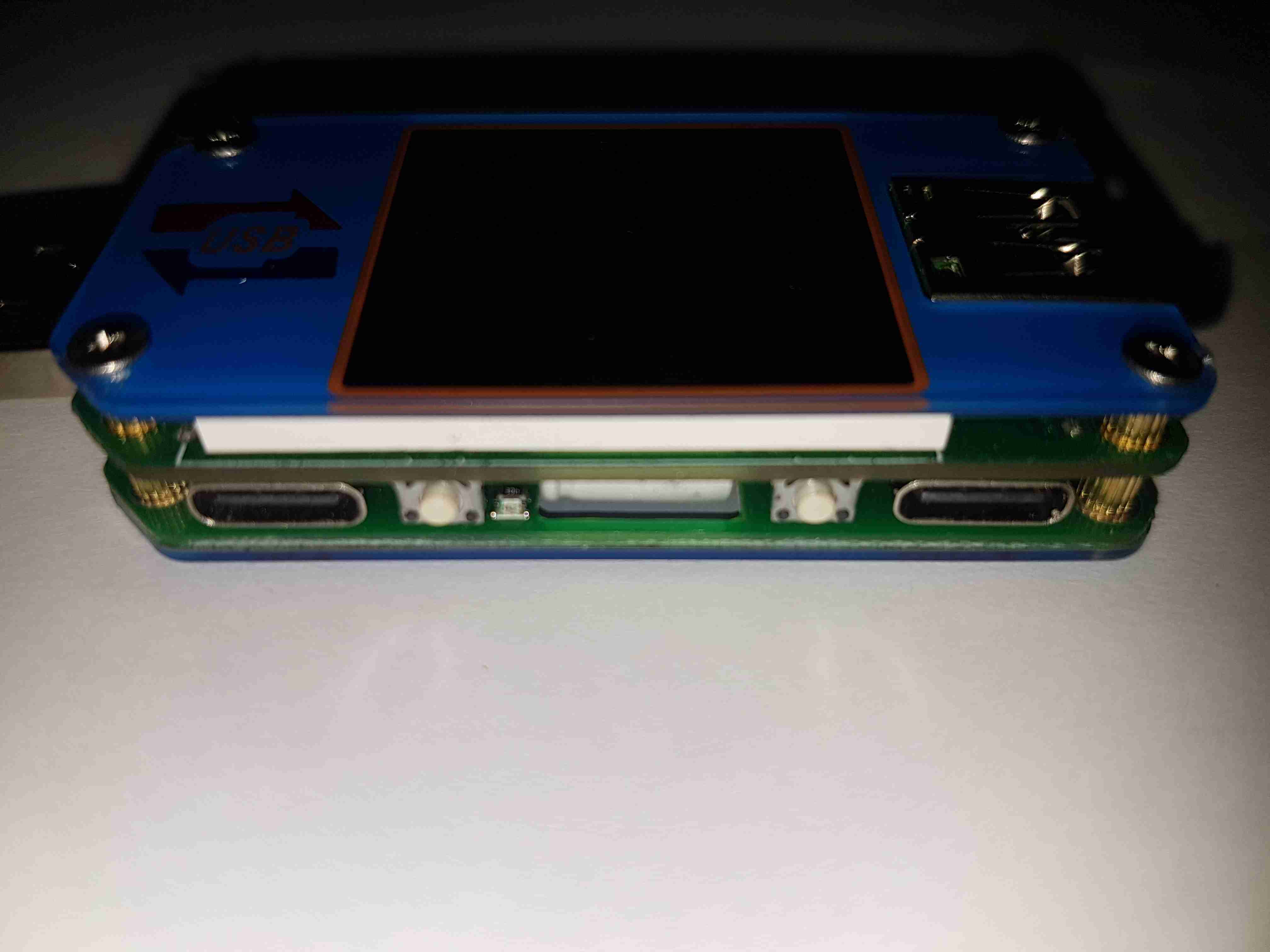
Here’s a nice little feature-packed USB power meter, the UM25C. This unit has USB-C along with the usual USB type A connectors, along with a bluetooth radio for remote monitoring of stats via a Windows or Android app. Construction is nice, it’s a stack of two PCBs, and polycarbonate cover plates, secured together with brass posts & screws.
Back Cover
The back cover has the legend for all the side connectors, along with the logo.
USB Micro Input
Down the sides are the user interface buttons, and here the Micro-B input connector. The 4-pin header is visible here that takes serial data down to the bluetooth section.
USB-C Connectors
The other side has the remaining pair of buttons, and the USB-C I/O. I don’t yet own anything USB-C based, but this is good future proofing.
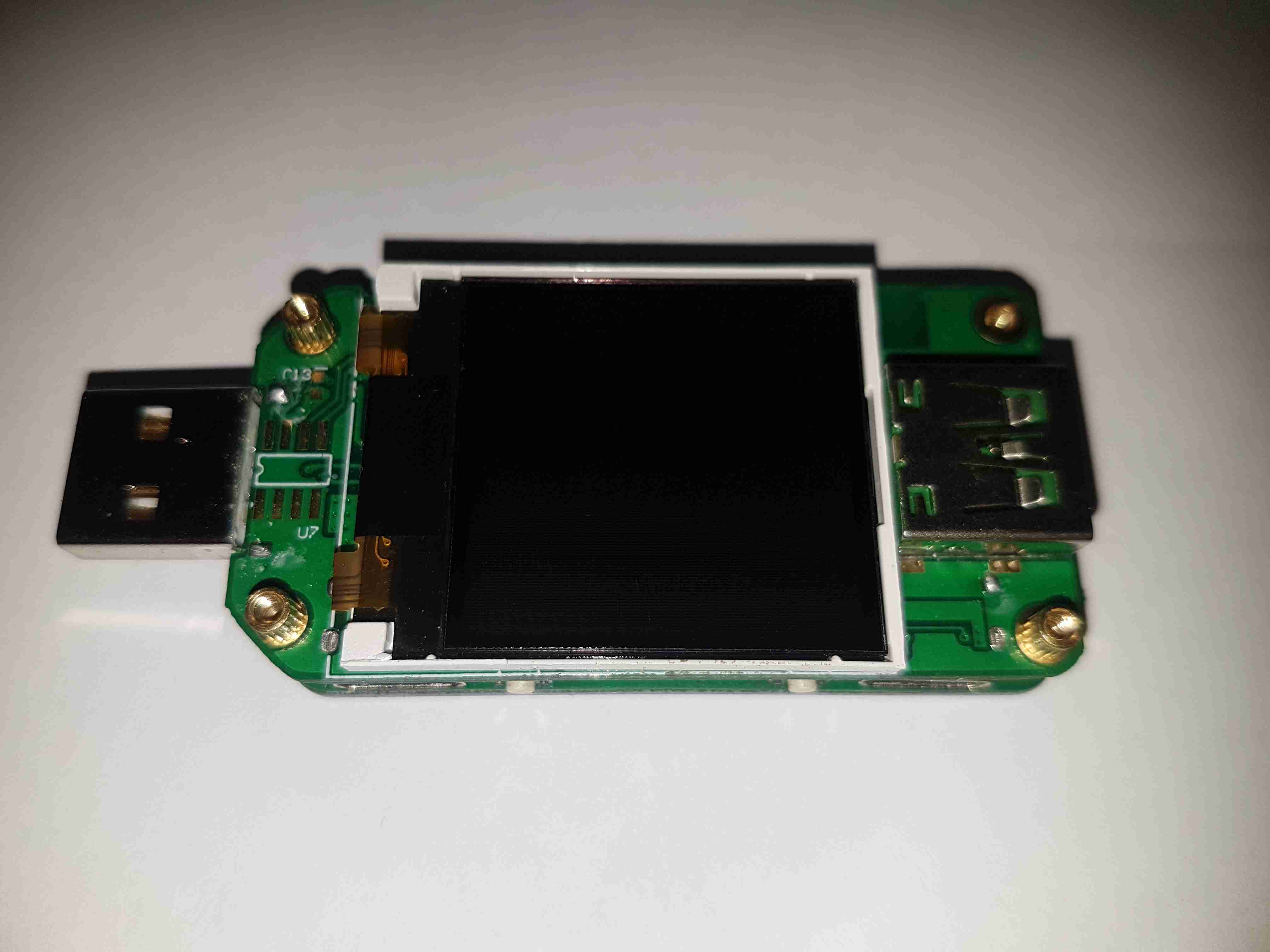
LCD Display
Removing the top plastic cover plate reveals the small 1″ TFT LCD module. This will be hot-bar soldered underneath the screen. There’s an unused footprint next to the USB input connector, judging by the pin layout it’s probably for a I²C EEPROM.
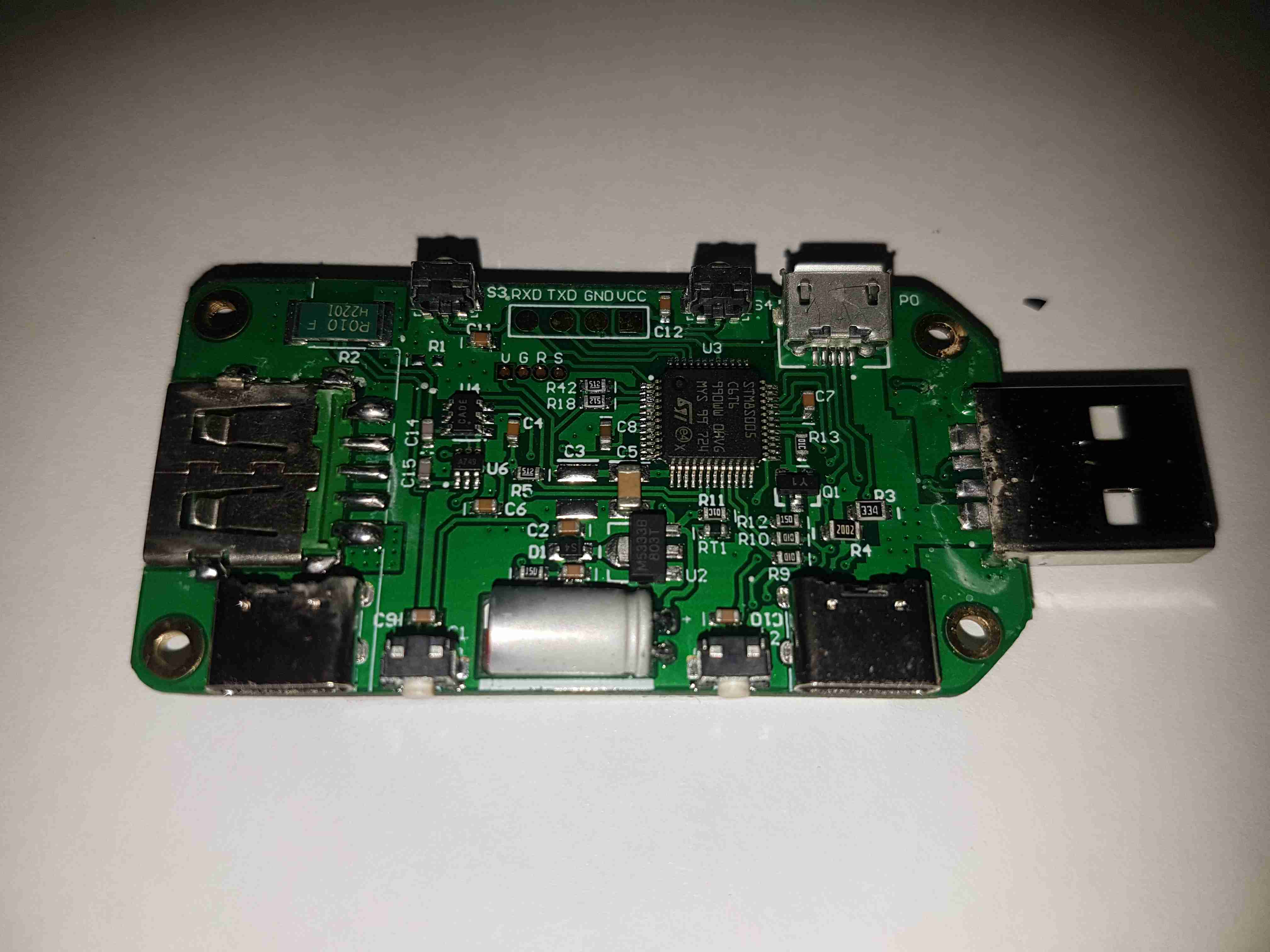
Main Board Components
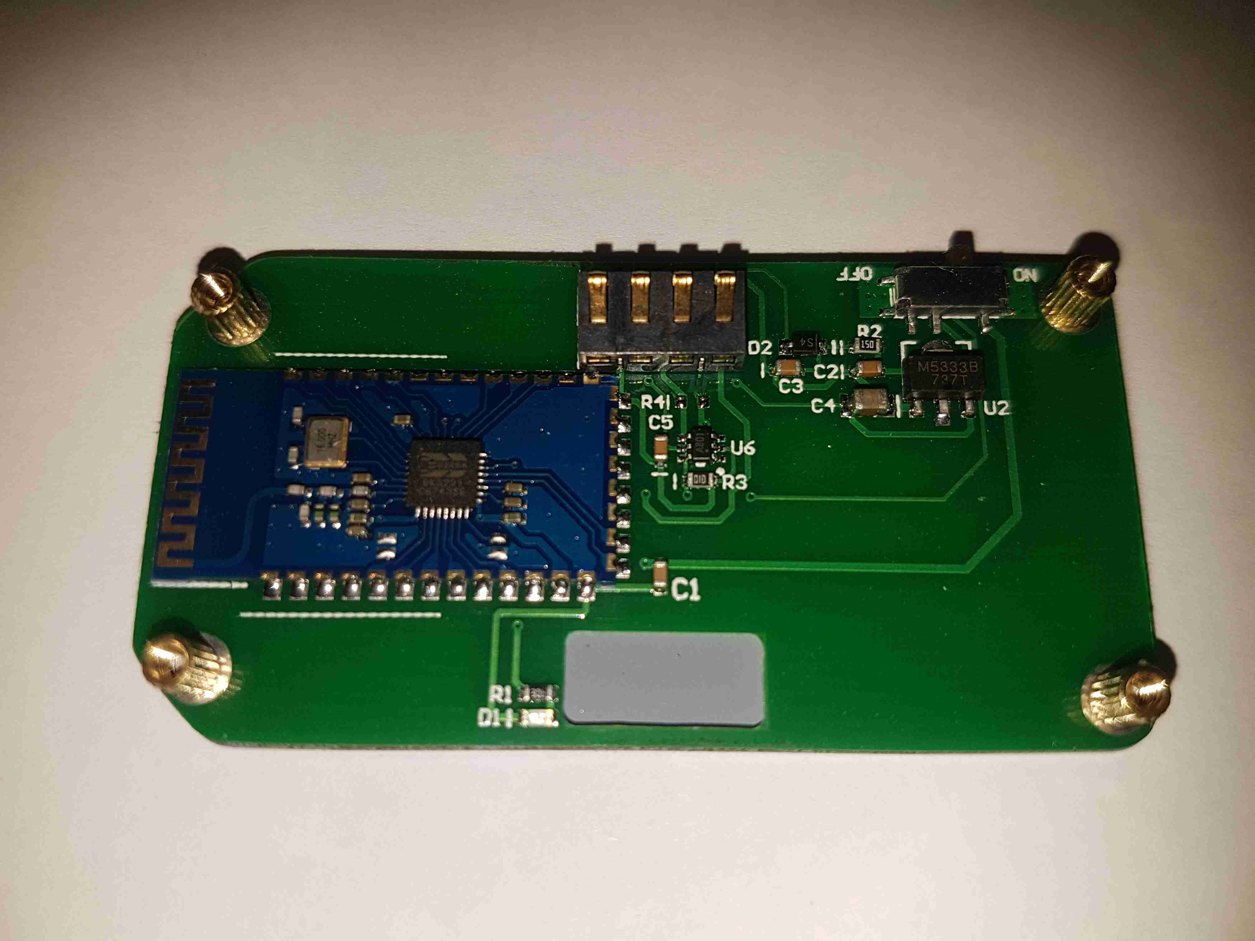
The underside of the top PCB has all the main components. The brains of the operation is a ST STM8S005C6T6 microcontroller. It’s at the basic end of the STM range, with a 16MHz clock, 32K flash, EEPROM, 10-bit ADC, SPI, UART & I²C. The main 0.010Ω current shunt is placed at the top left of the board in the negative rail. A couple of SOT-23 components in the centre of the board, I haven’t been able to identify properly, but I think they may be MOSFETs. The large electrolytic filter capacitor has a slot routed into the PCB to allow it to be laid flat. Providing the main power rail is a SOT-89 M5333B 3.3v LDO regulator.
Bluetooth Radio
The bottom board contains the bluetooth radio module, this is a BK3231 Bluetooth HID SoC. The only profile advertised by this unit is a serial port. There’s a local 3.3v LDO regulator & support components, along with an indicator LED.
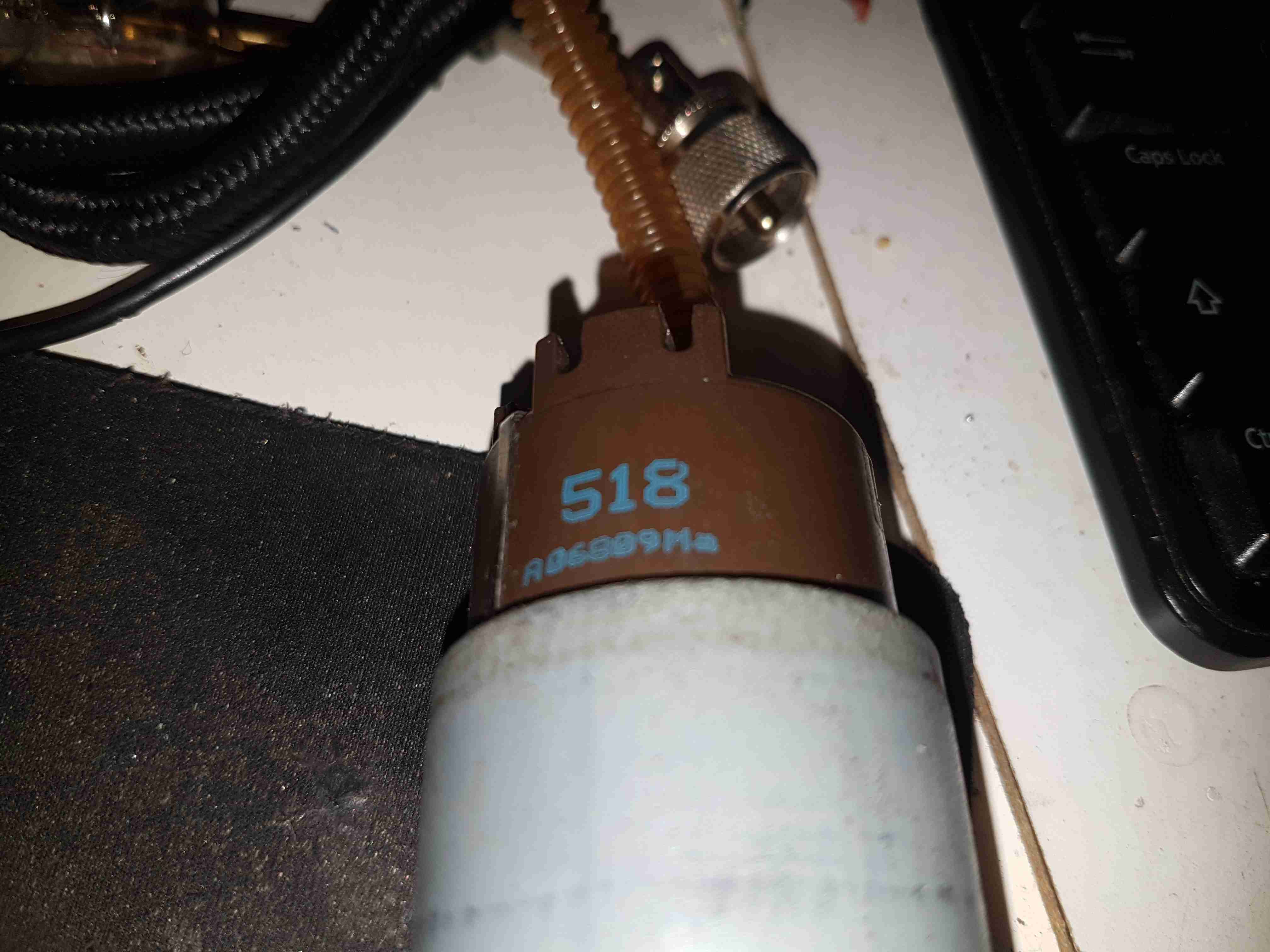
Here’s a destructive teardown of an automotive in-tank turbine fuel pump, used on modern Petrol cars. These units sit in the tank fully immersed in the fuel, which also circulates through the motor inside for cooling. These pumps aren’t serviceable – they’re crimped shut on both ends. Luckily the steel shell is thin, so attacking the crimp joint with a pair of mole grips & a screwdriver allowed me inside.
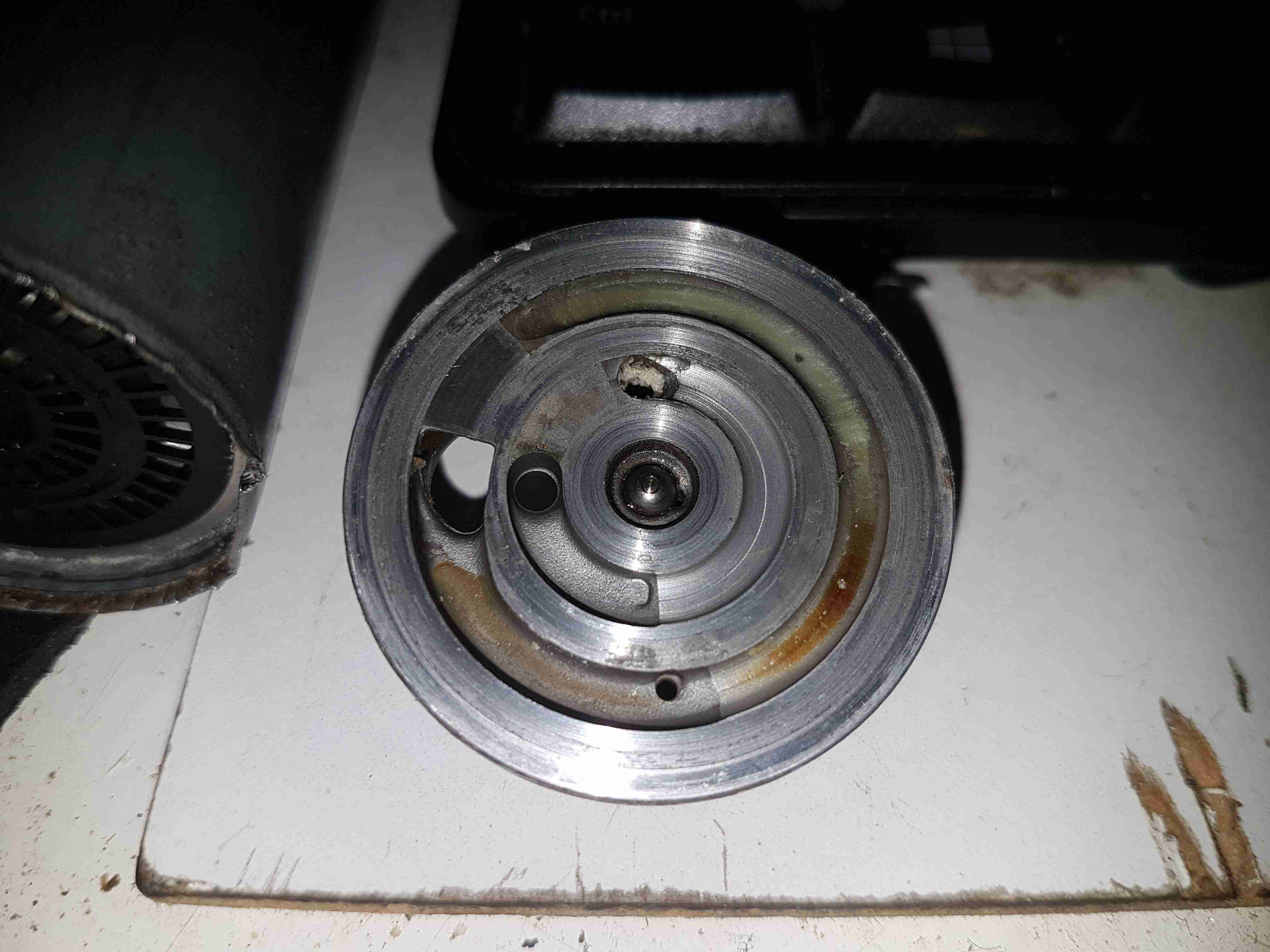
End Bell
The input endbell of the pump has the fuel inlet ports, the channels are visible machined into the casting. There’s a pair of channels for two pump outputs – the main fuel rail to the engine, and an auxiliary fuel output to power a venturi pump. The fuel pump unit sits inside a swirl pot, which holds about a pint of fuel. These are used to ensure the pump doesn’t run dry & starve the engine when the tank level is low & the car is being driven hard. The venturi pump draws fuel from the main tank into the swirl pot. A steel ball is pressed in to the end bell to provide a thrust bearing for the motor armature.
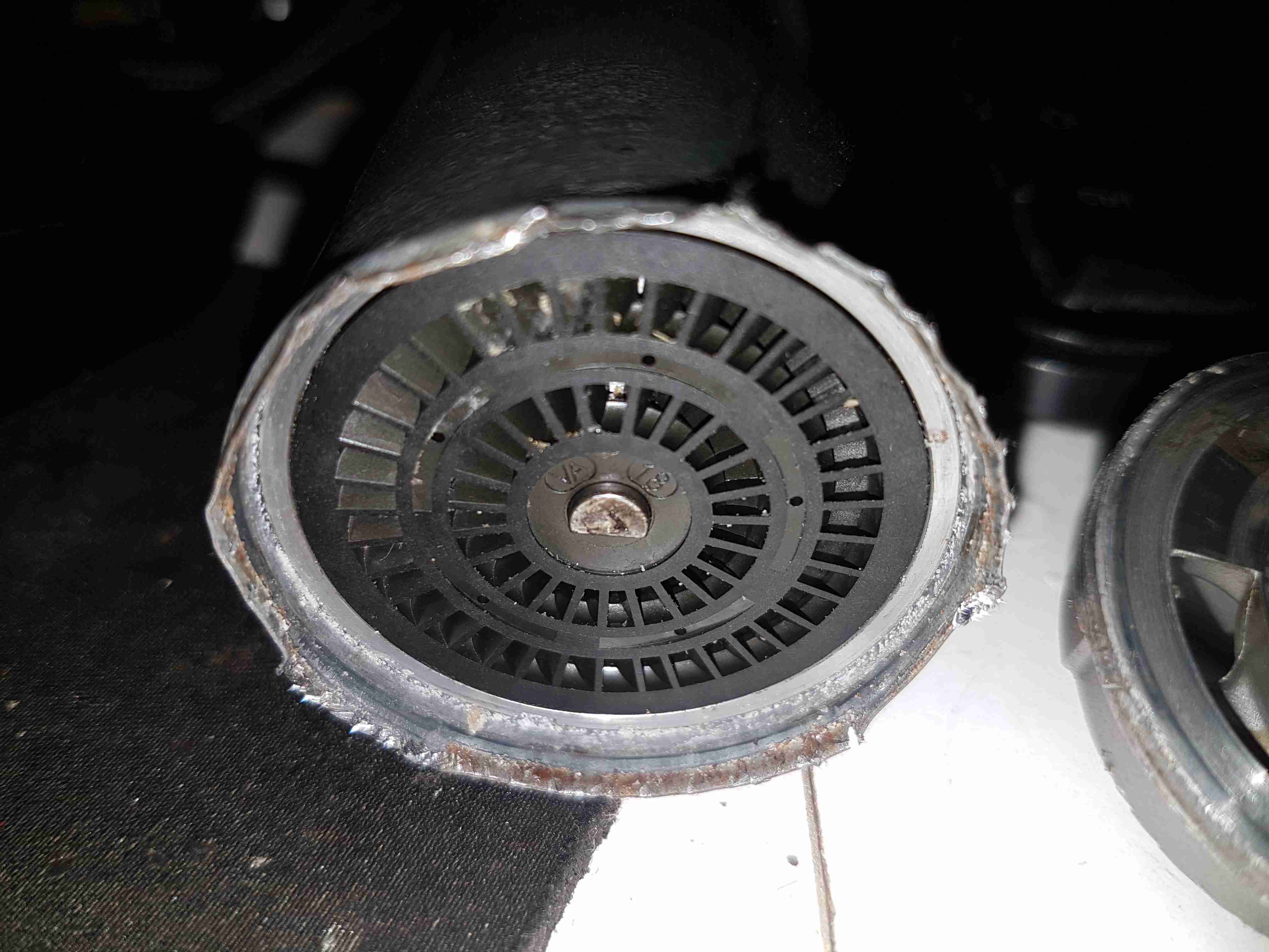
Turbine Impeller
The core of the pump is this impeller, which is similar to a side-channel blower. From what I’ve been able to find these units supply pressures up to about 70PSI for the injector rail. The outside ring is the main fuel pump, while the smaller inner one provides the pressure to run the venturi pump.
Pump Housing
The other side of the machined pump housing has the main output channel, with the fuel outlet port at the bottom. The motor shaft is supported in what looks like a carbon bearing.
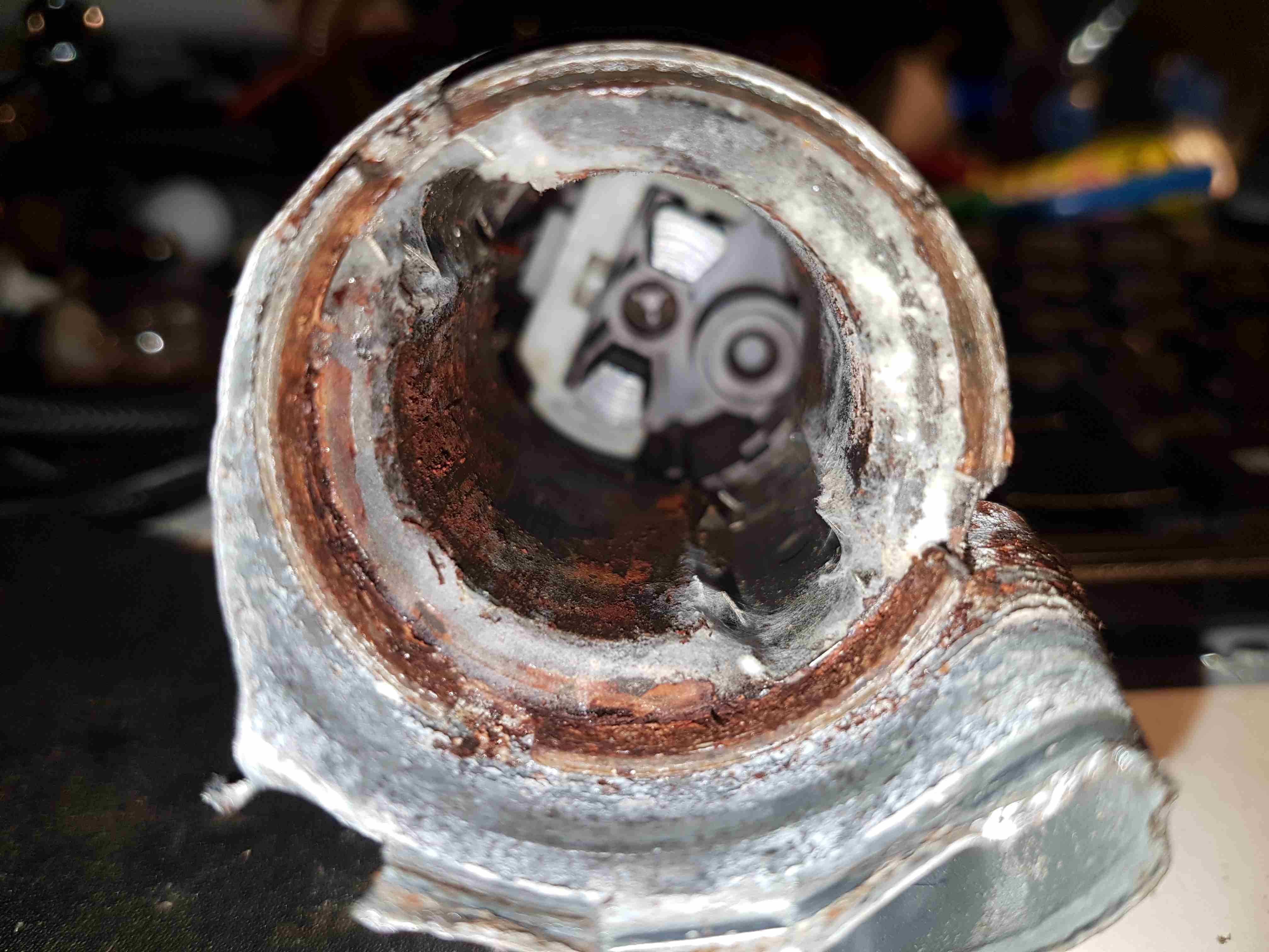
Midsection
Removing the pump intermediate section with the bearing reveals quite a bit of fungus – it’s probably been happy sat in here digesting what remains of the fuel.
Armature Exposed
Some peeling with mole grips allows the motor to come apart entirely. The drive end of the armature is visible here.
Motor Can
The outer shell of the motor holds yet more fungus, along with some rust & the pair of ceramic permanent magnets.
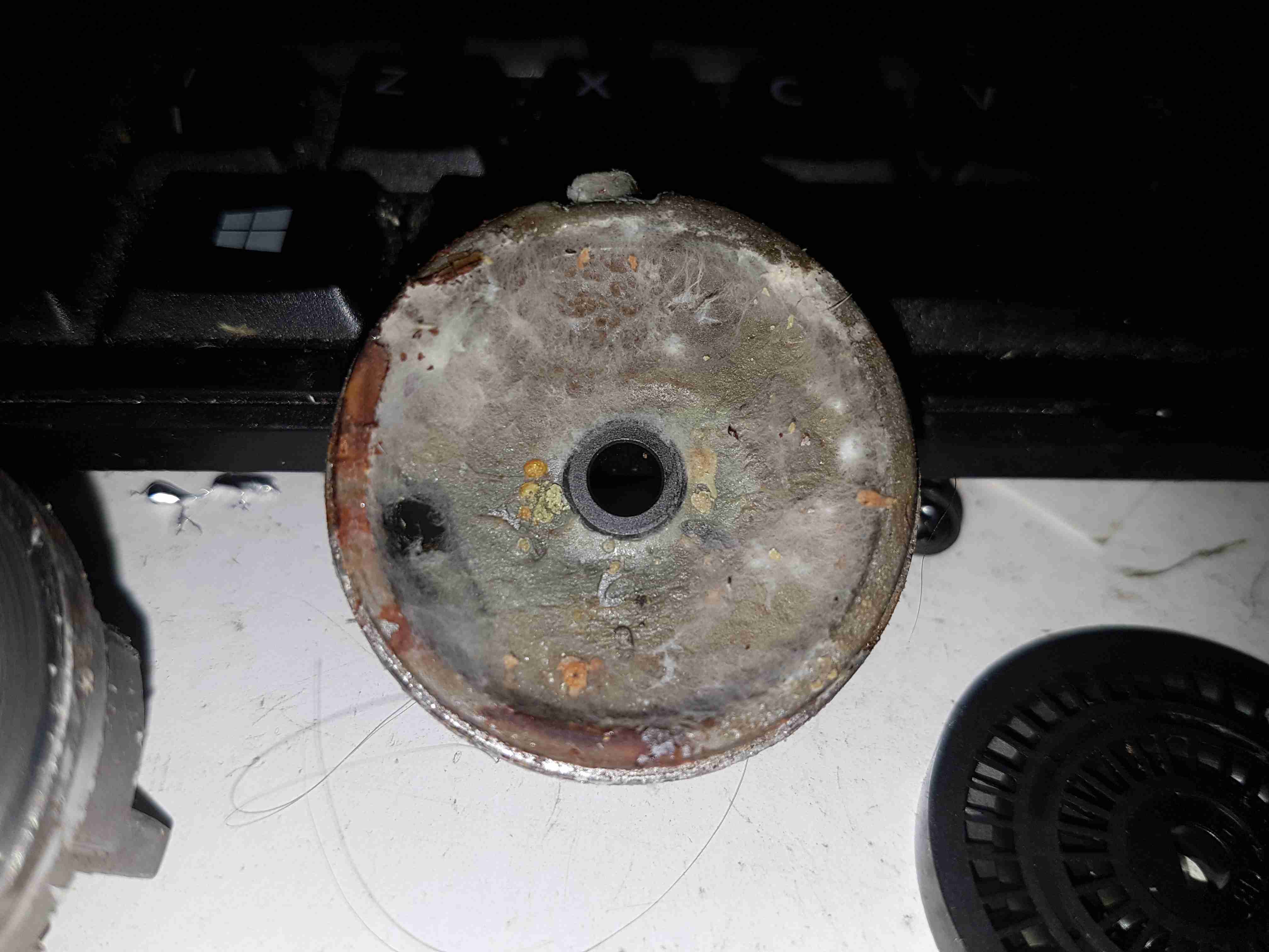
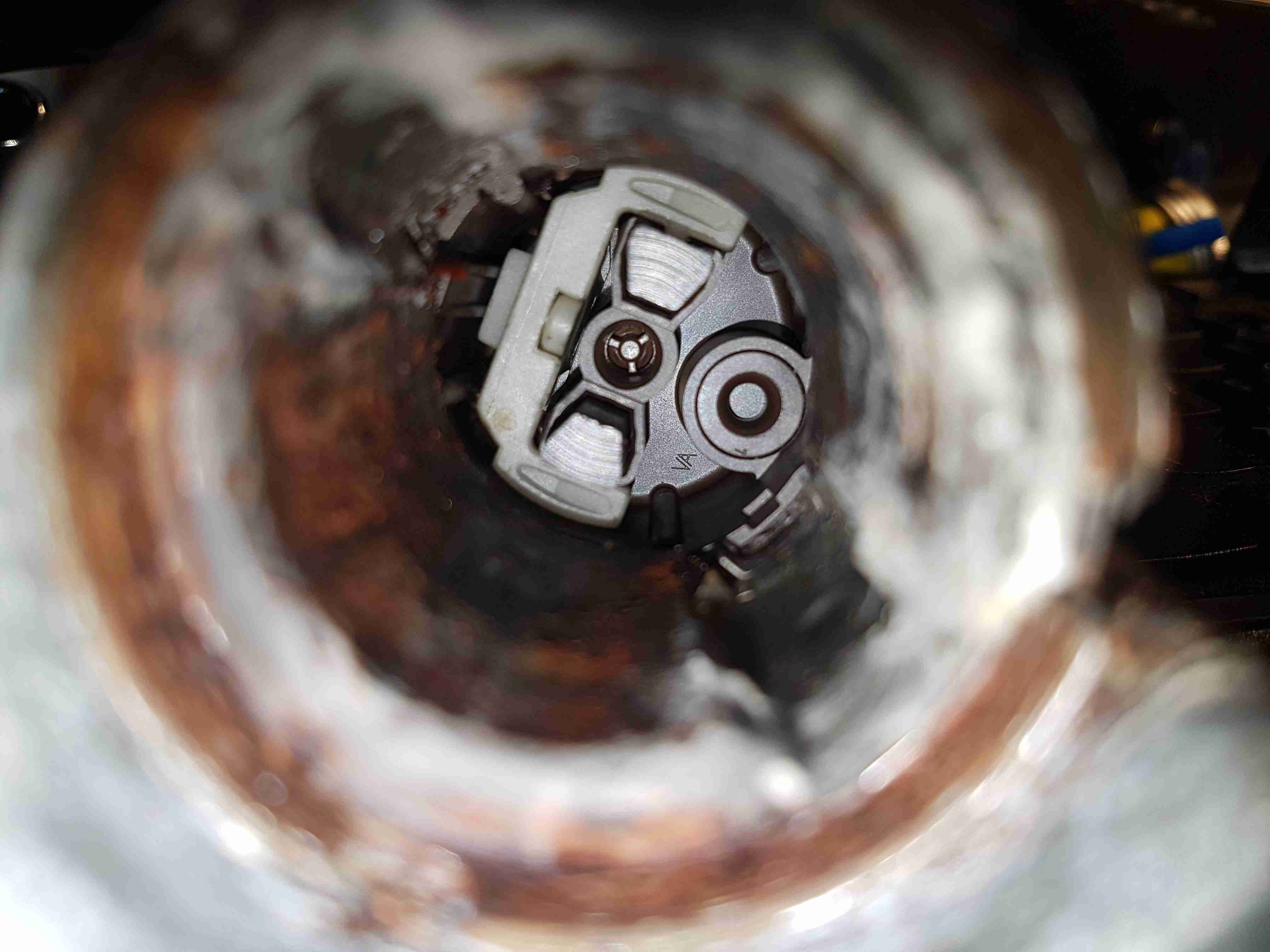
Brushes
The other end of the pump has the brush assembly, and the fuel outlet check valve to the right. The bearing at this end is just the plastic end cap, since there are much lower forces at this end of the motor. The fuel itself provides the lubrication required.
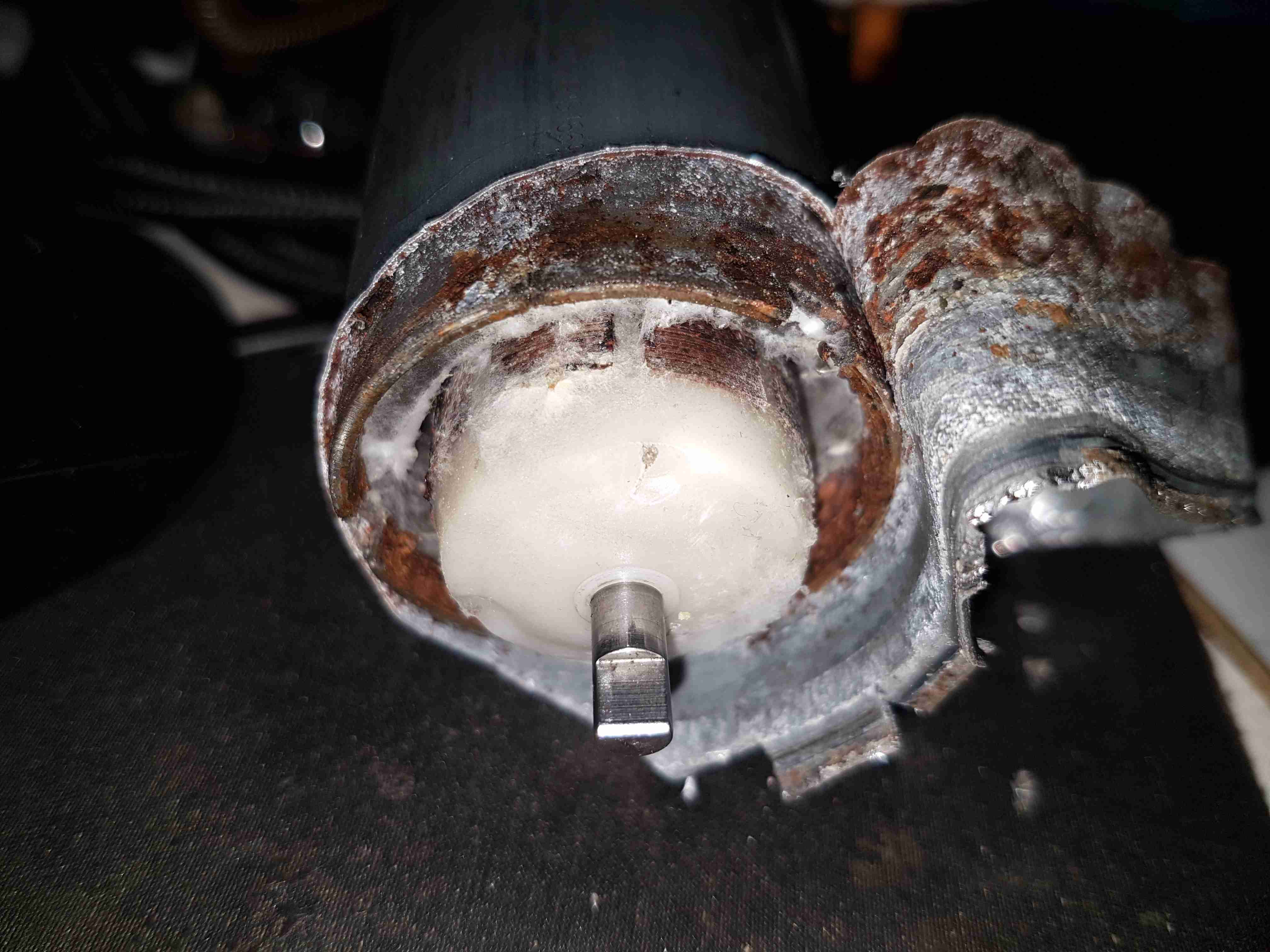
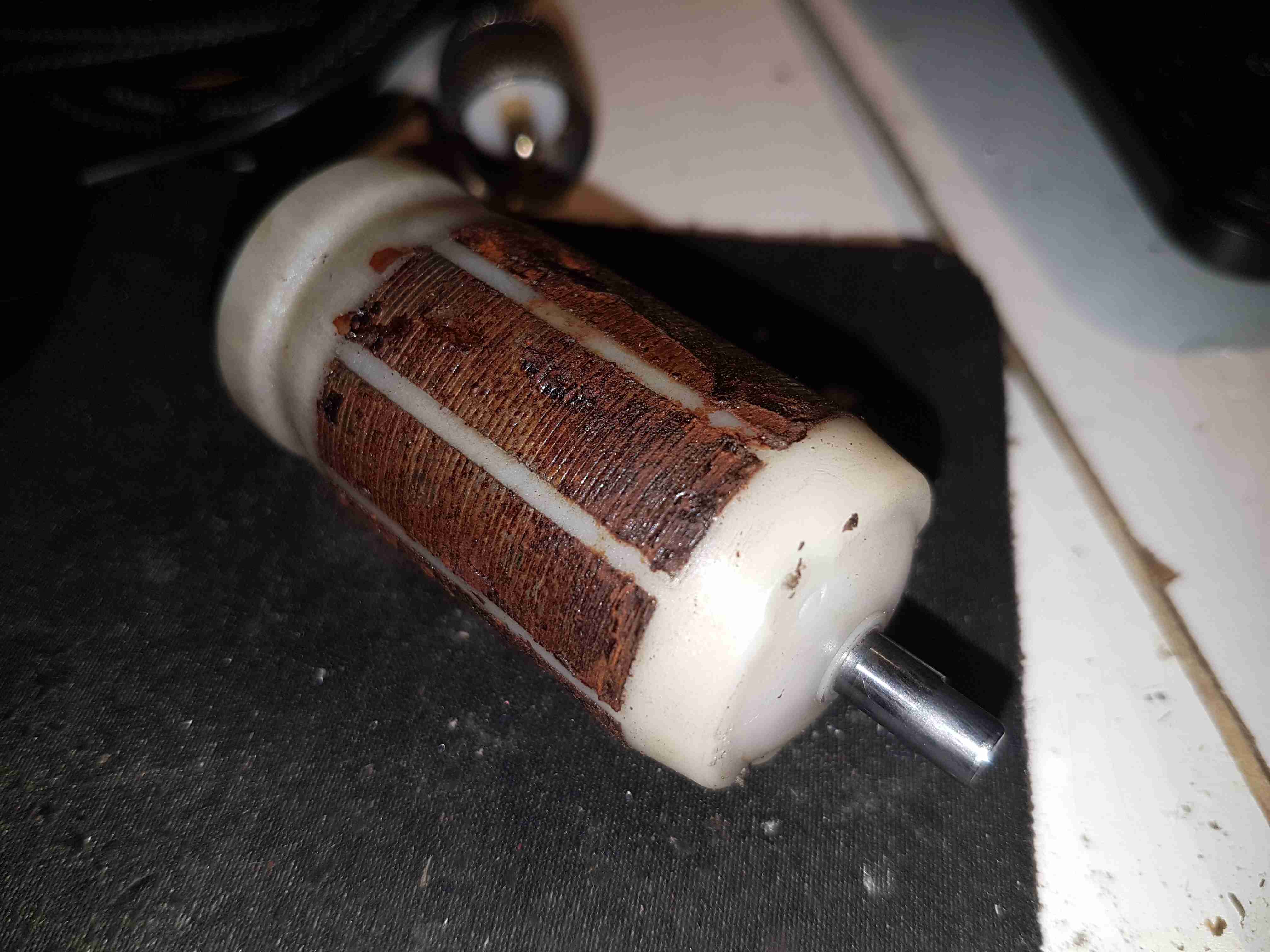
Potted Armature
With the armature pulled out of the housing, it’s clear that there’s been quite a bit of water in here as well, with the laminations rusting away. This armature is fully potted in plastic, with none of the copper windings visible.
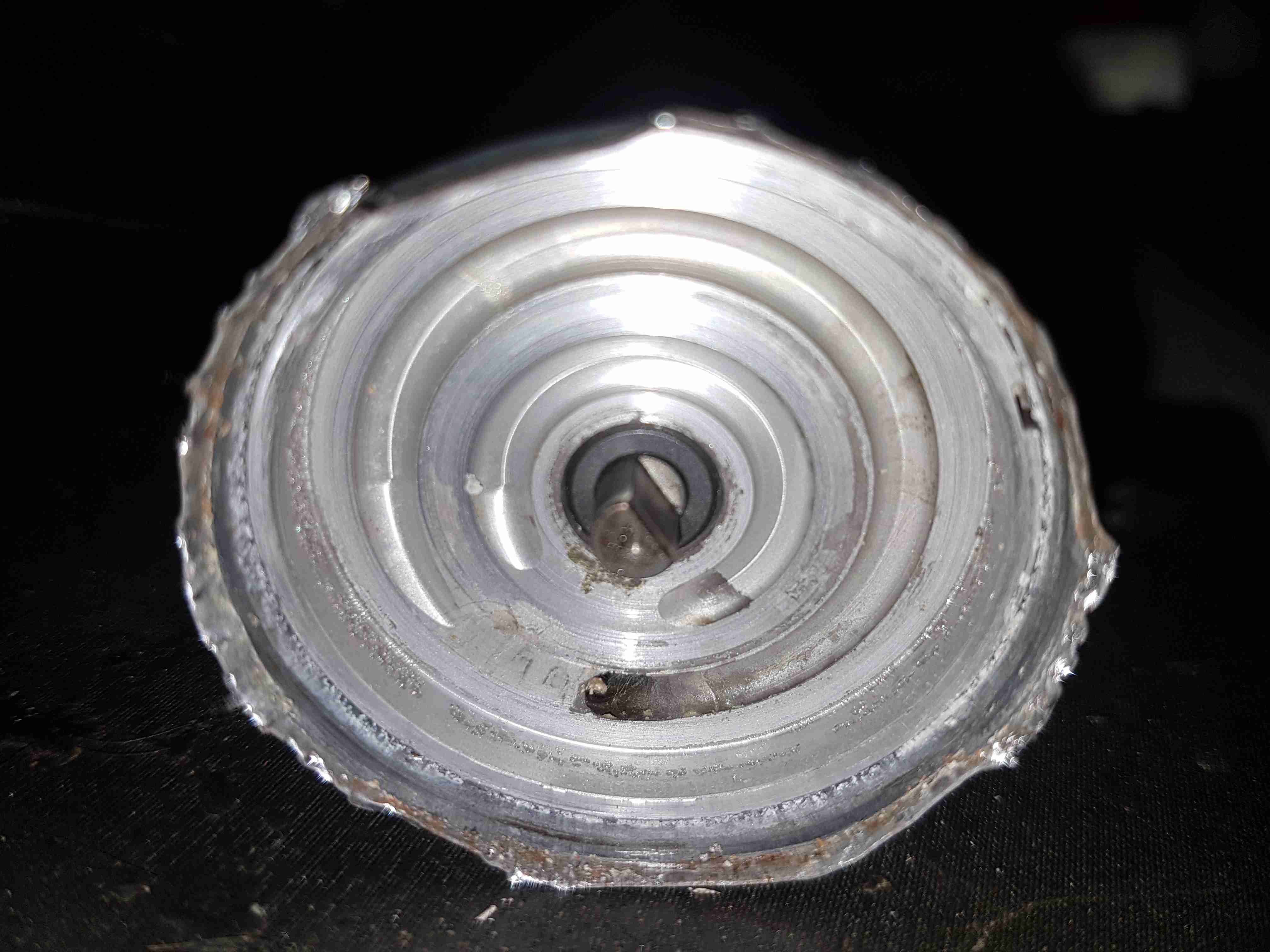
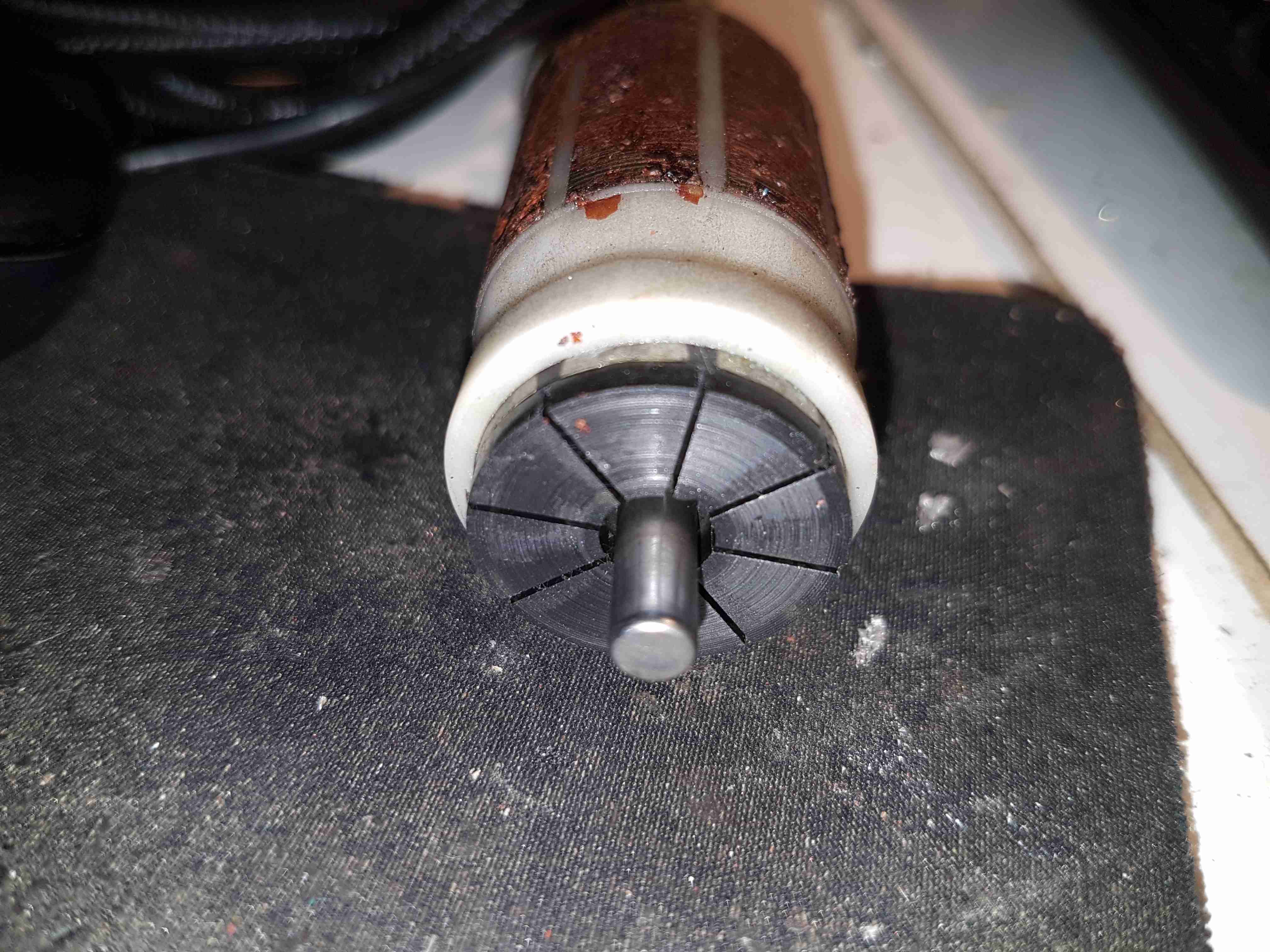
Carbon Commutator
The commutator in these motors is definitely a strange one – it’s axial rather than radial in construction, and the segments are made of carbon like the brushes. No doubt this is to stop the sparking that usually occurs with brushed motors – preventing ignition of fuel vapour in the pump when air manages to get in as well, such as in an empty tank.
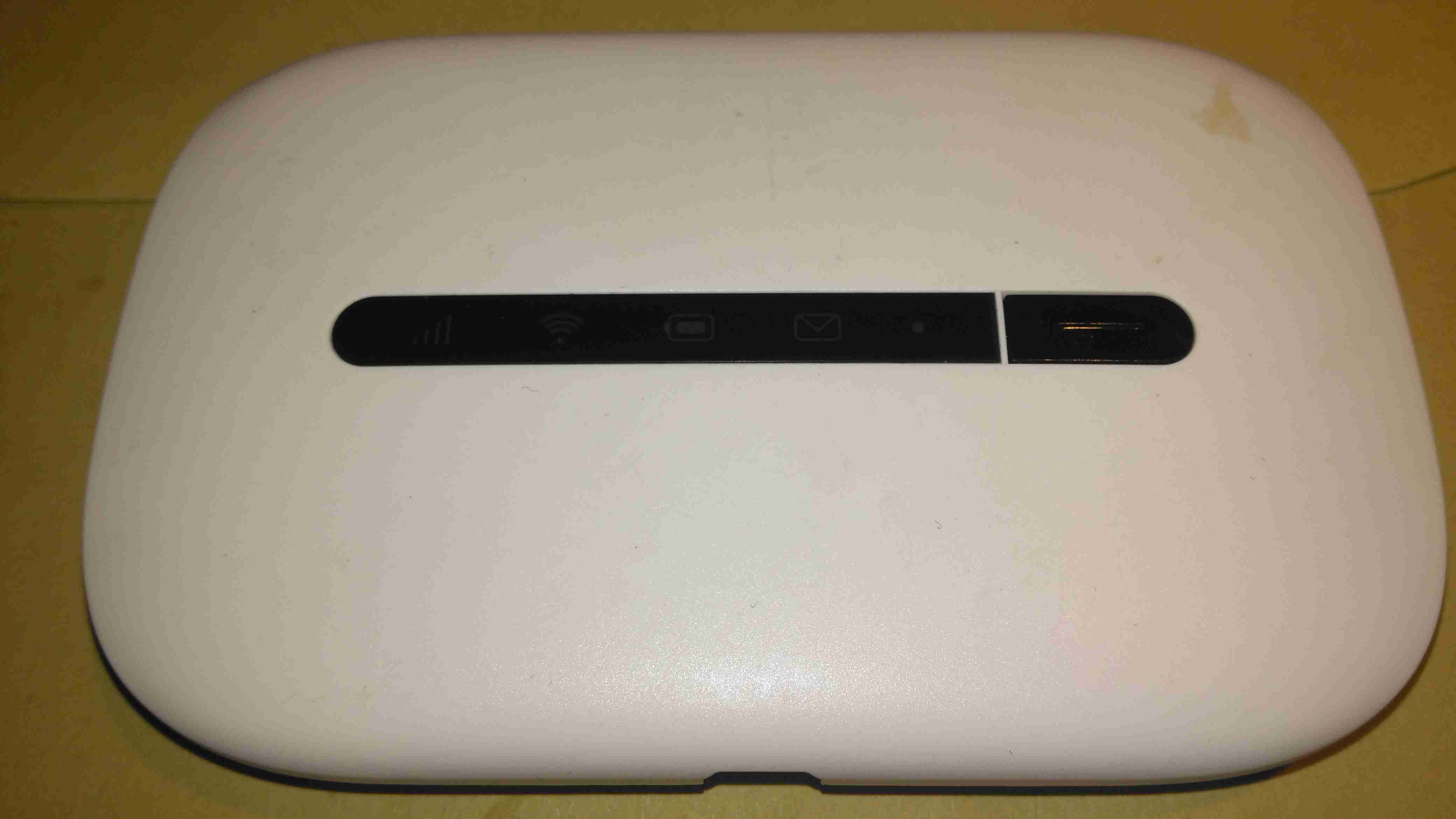
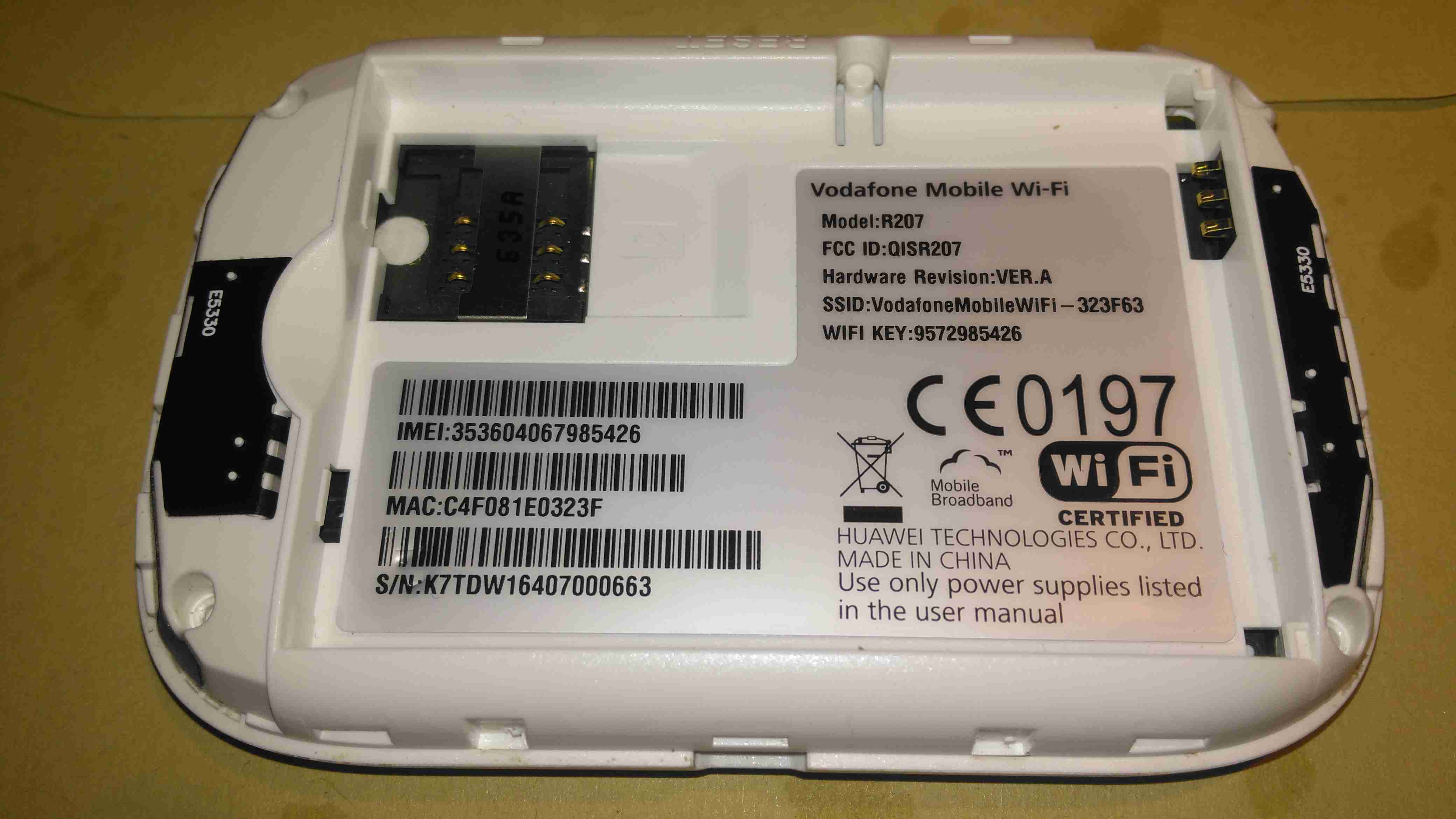
Here’s one of the old modems from my spares bin, a Vodafone Mobile WiFi R207. This is just a rebranded Huawei E5330. This unit includes a 3G modem, and a WiFi chipset, running firmware that makes this a mini-router, with NAT.
Specs
The back has the batter compartment & the SIM slot, with a large label showing all the important details.
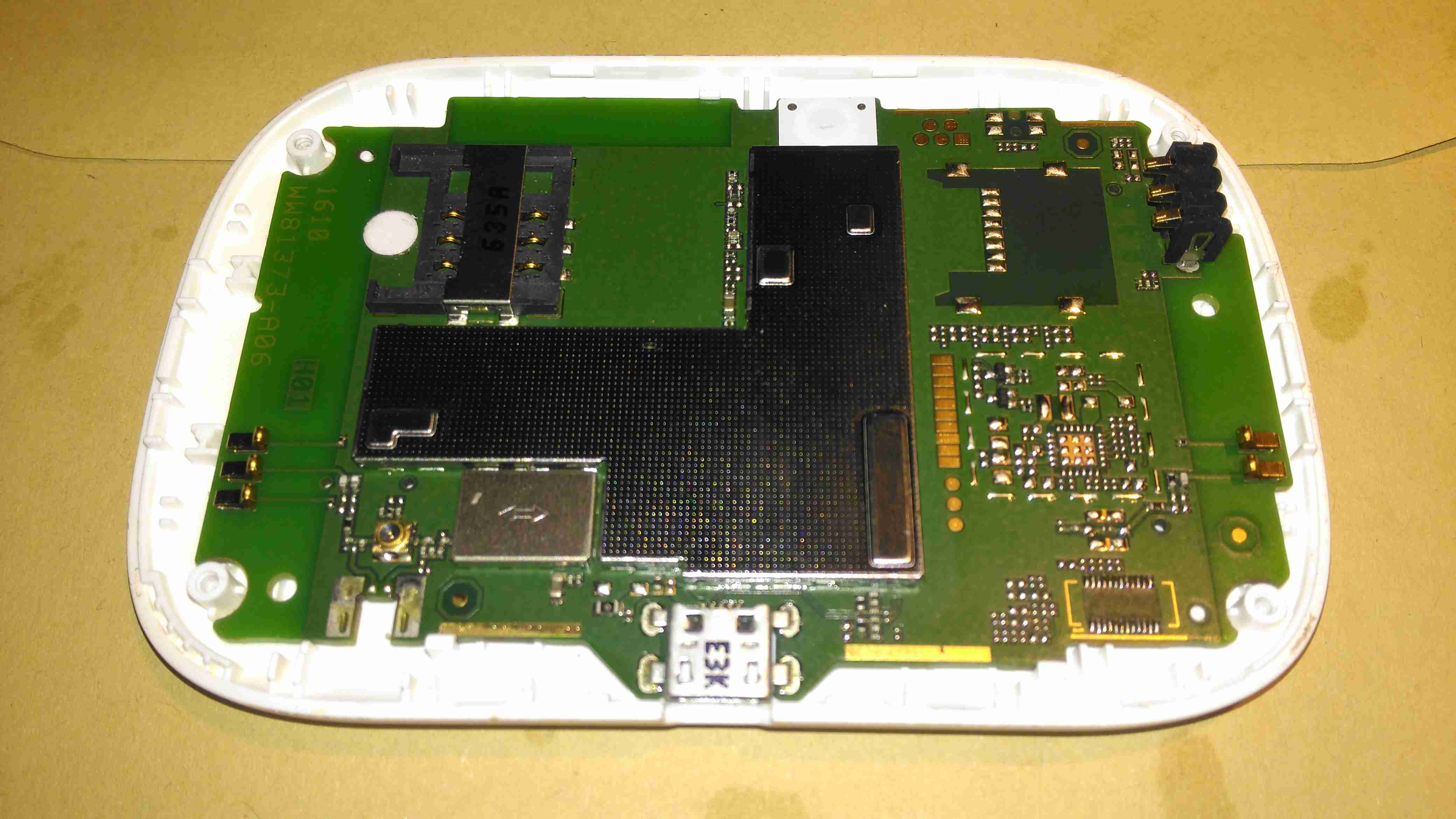
Cover Removed
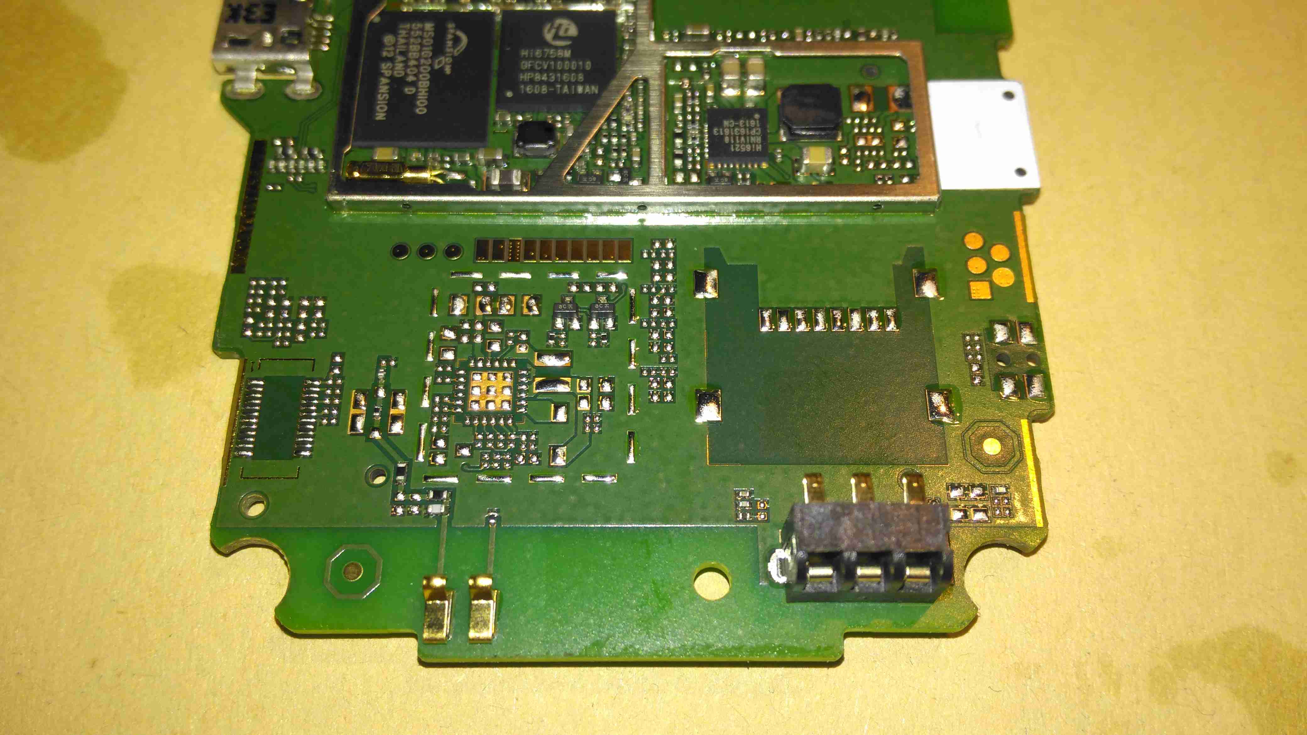
A couple of small Torx screws later & the shell splits in half. All the electronics are covered by shields here, but luckily they are the clip-on type, and aren’t soldered direct to the PCB.
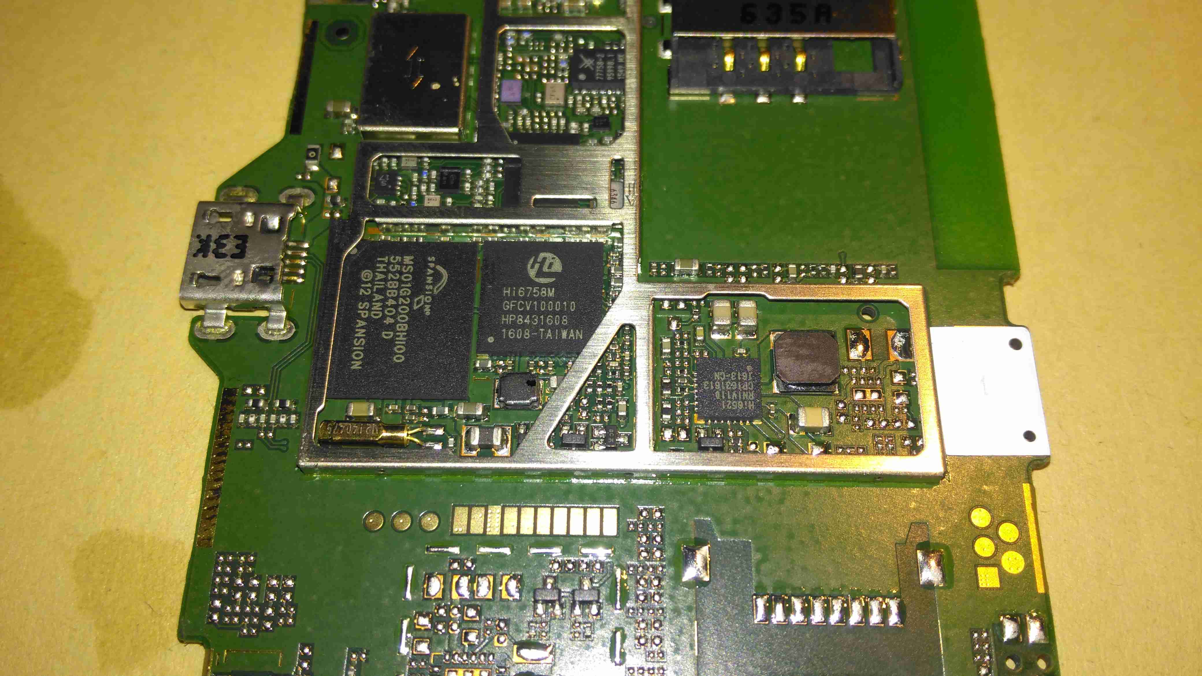
Chipset
Once the shield has been removed, the main chipset is visible underneath. There’s a large Spansion MS01G200BHI00 1GBit flash, which is holding the firmware. Next to that is the Hi6758M baseband processor. This has all the hardware required to implement a 3G modem. Just to the right is a Hi6521 power management IC, which is dealing with all the power supplies needed by the CPU.
The RF section is above the baseband processor, some of which is hiding under the bits of the shield that aren’t removable.
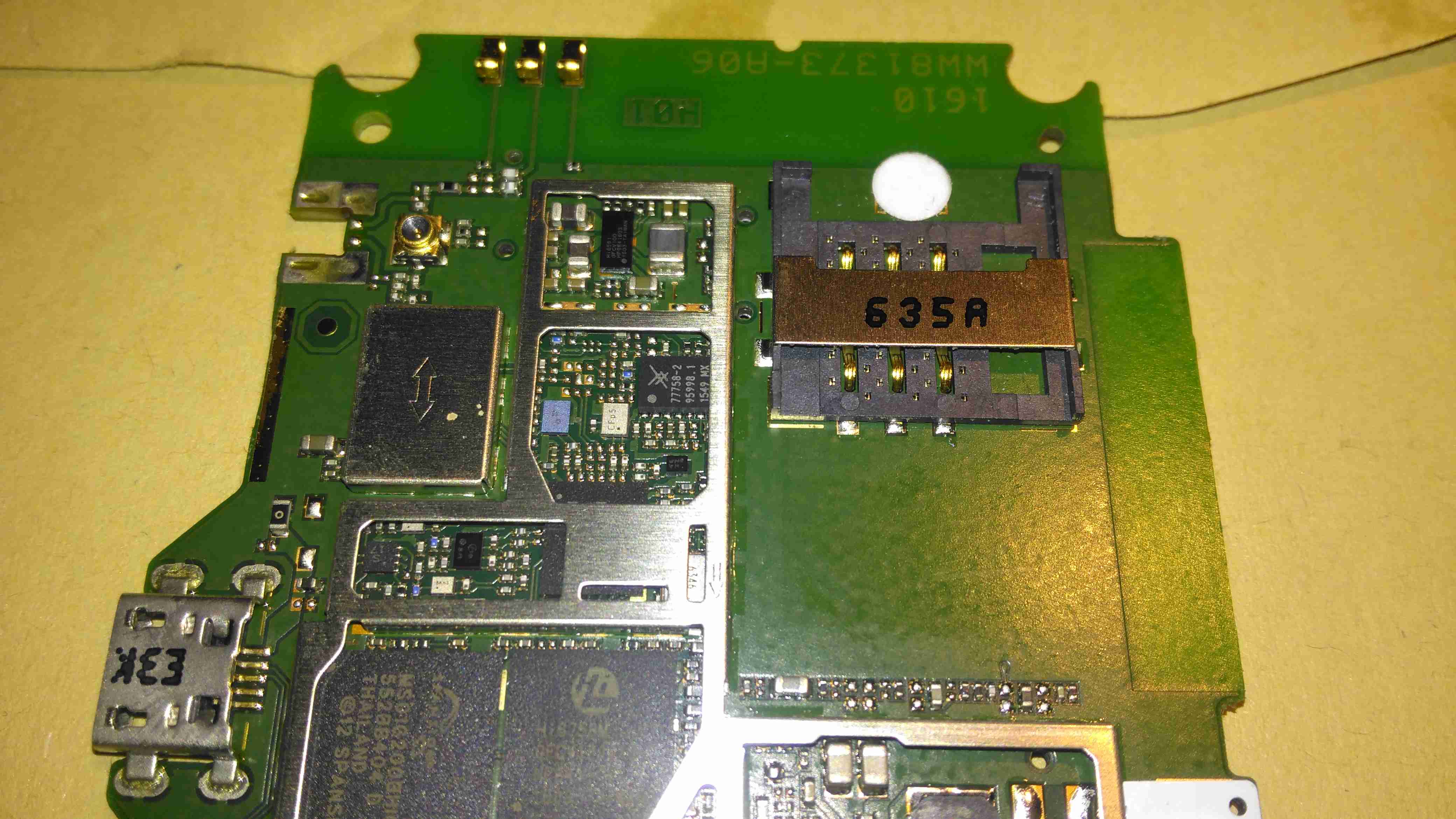
SIM Socket
There’s a socket onboard for a standard Mini-SIM, just to the left of that is a Hi6561 4-phase buck converter. I would imagine this is providing the power supplies for the RF section & amplifier.
Unpopulated Parts
Not sure what this section is for, all the parts are unpopulated. Maybe a bluetooth option?
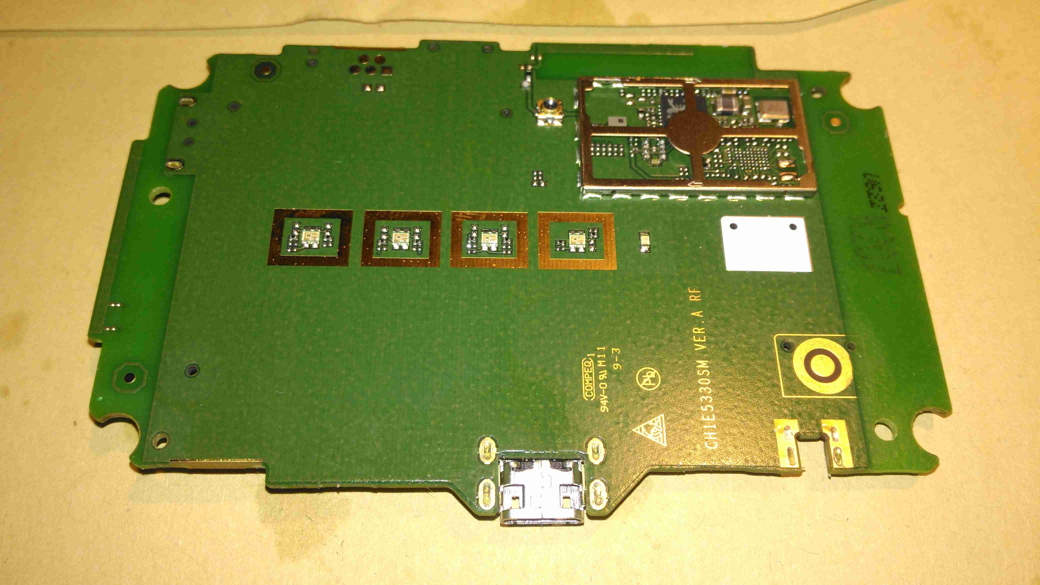
PCB Reverse
The other side of the PCB is pretty sparse, holding just the indicator LEDS, button & the WiFi Chipset.
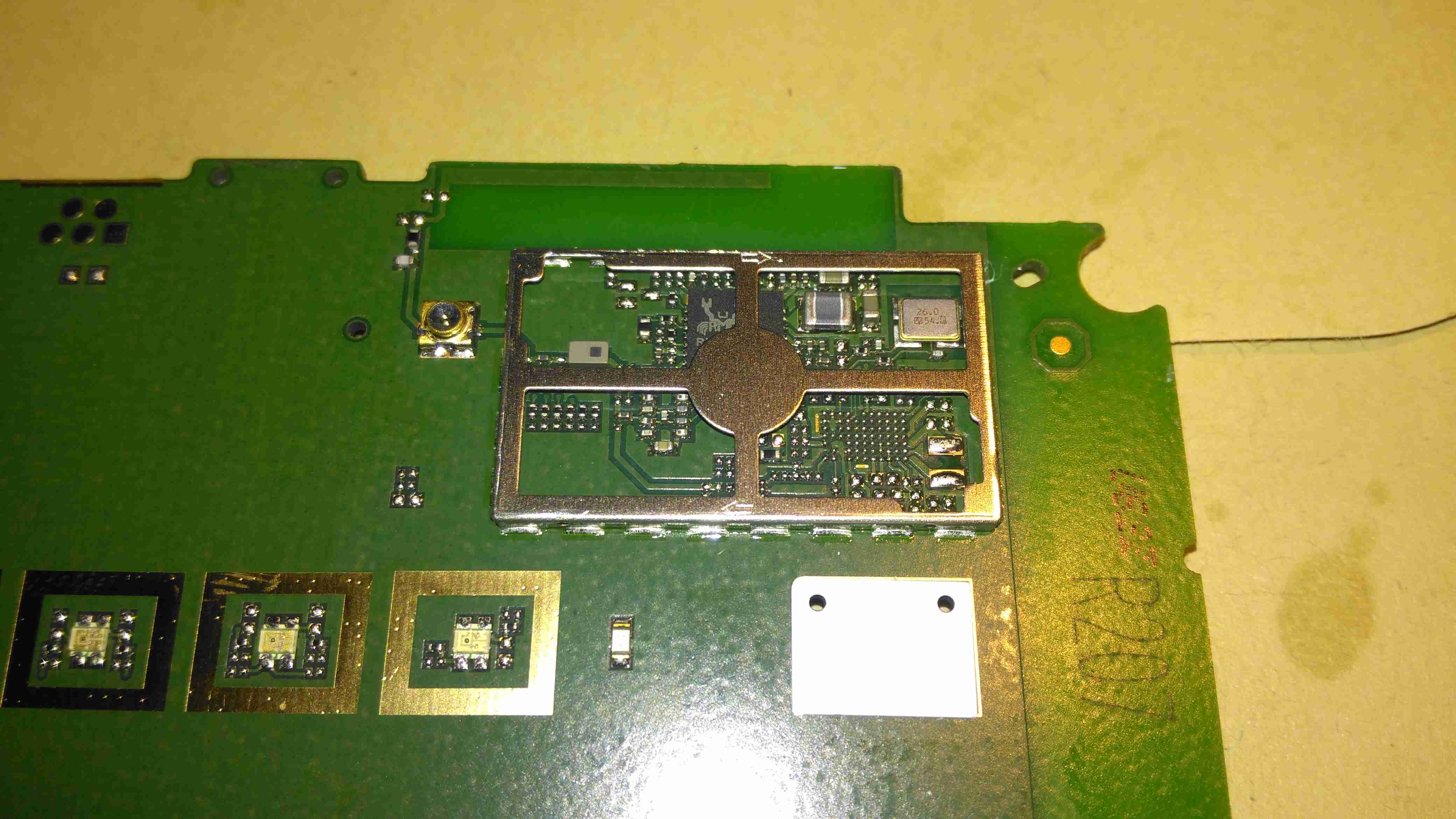
Realtek WiFi Chipset
The chipset here is a Realtek part, but it’s number is hidden by some of the shield. The antenna connection is routed to the edge of the board, where a spring terminal on the plastic case mounted antenna makes contact.
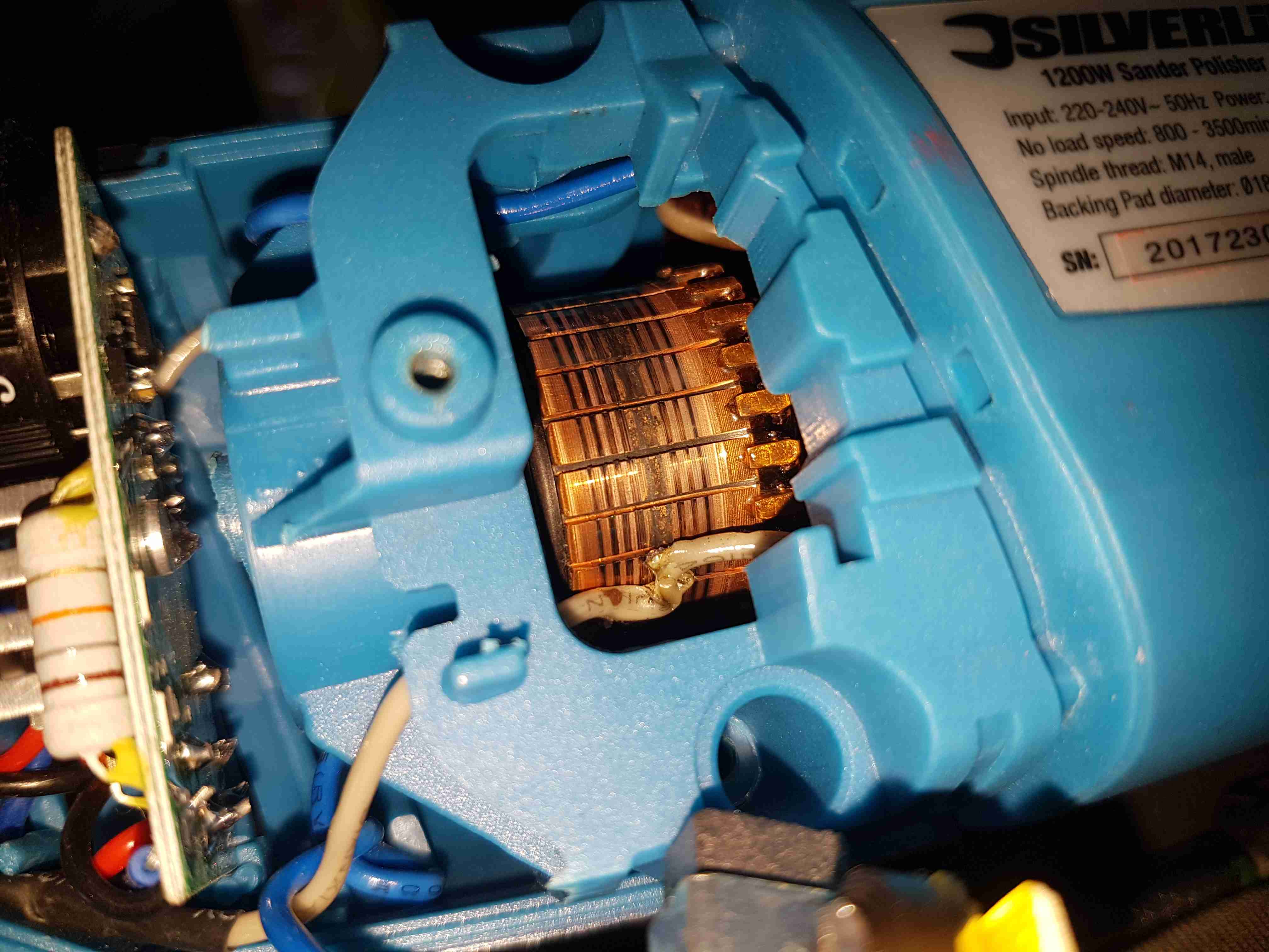
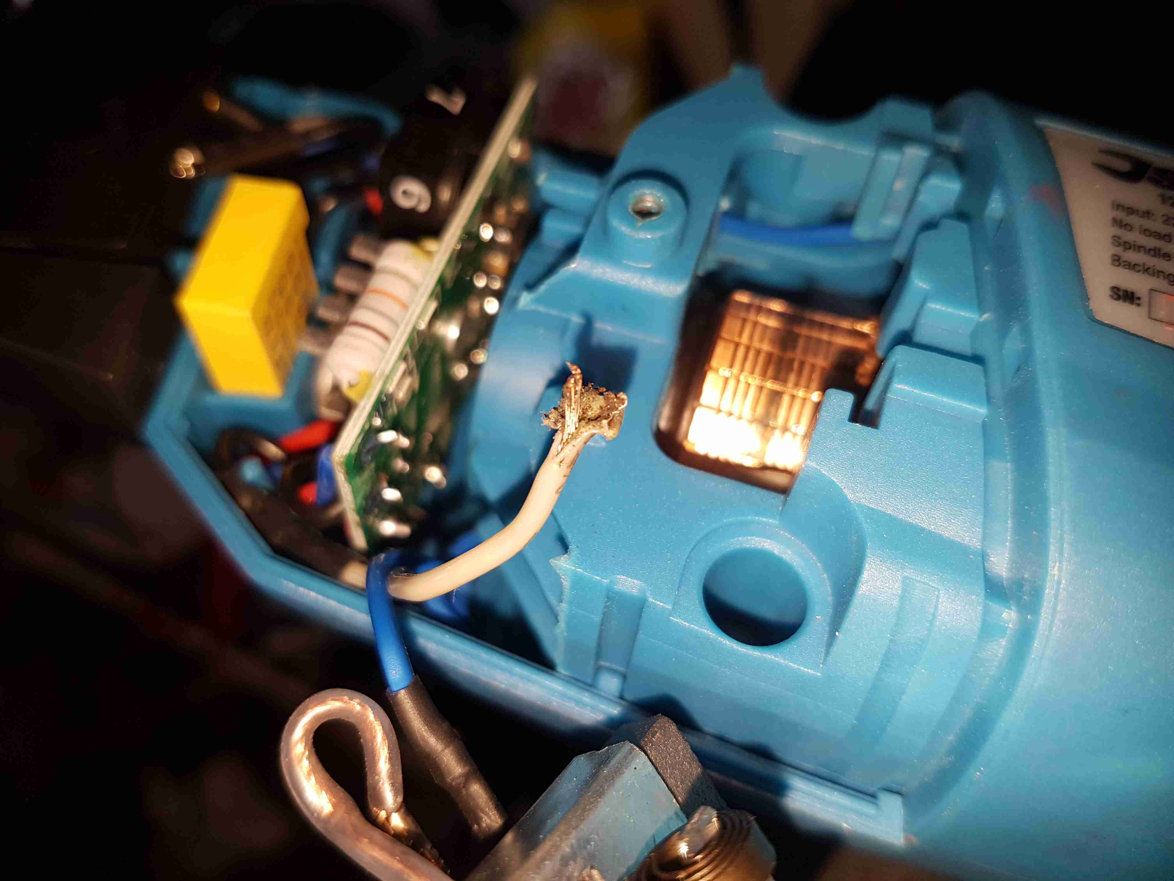
Since I seem to be the local go-to for any dead electrical equipment, this brand-new Silverline polisher has landed on my desk. Purchased cheap from an auction this was dead on arrival. Checking the fuse revealed nothing suspect, so a quick teardown to find the fault was required.
Above is a photo of the commutator with the brush holder removed, and the source of the issue. The connection onto the field winding of the universal motor has been left unsecured, as a result it’s managed to move into contact with the commutator.
This has done a pretty good job of chewing it’s way through the wire entirely. There is some minor damage to the commutator segments, but it’s still smooth, and shouldn’t damage the brushes.
Chewed Wire
A quick pull on what’s left of the wire reveals the extent of the problem. It’s entirely burned through! Unfortunately the stator assembly with the field windings is pressed into the plastic housing, so it’s not removable. An in-place solder joint was required to the very short remains of the wire inside the housing. Once this was done the polisher sprang to life immediately, with no other damage.
This unit probably ended up at an auction as a factory reject, or a customer return to a retail outlet. If the latter, I would seriously question the quality control procedures of Silverline tools. 😉
The Sterling charger we’ve had on board nb Tanya Louise since Feb 2014 has bitten the dust, with 31220 hours on it’s internal clock. Since we’re a liveaboard boat, this charger has had a lot of use while we’re on the mooring during winter, when the solar bank isn’t outputting it’s full rate. First, a bit of a teardown to explore the unit, then onto the repair:
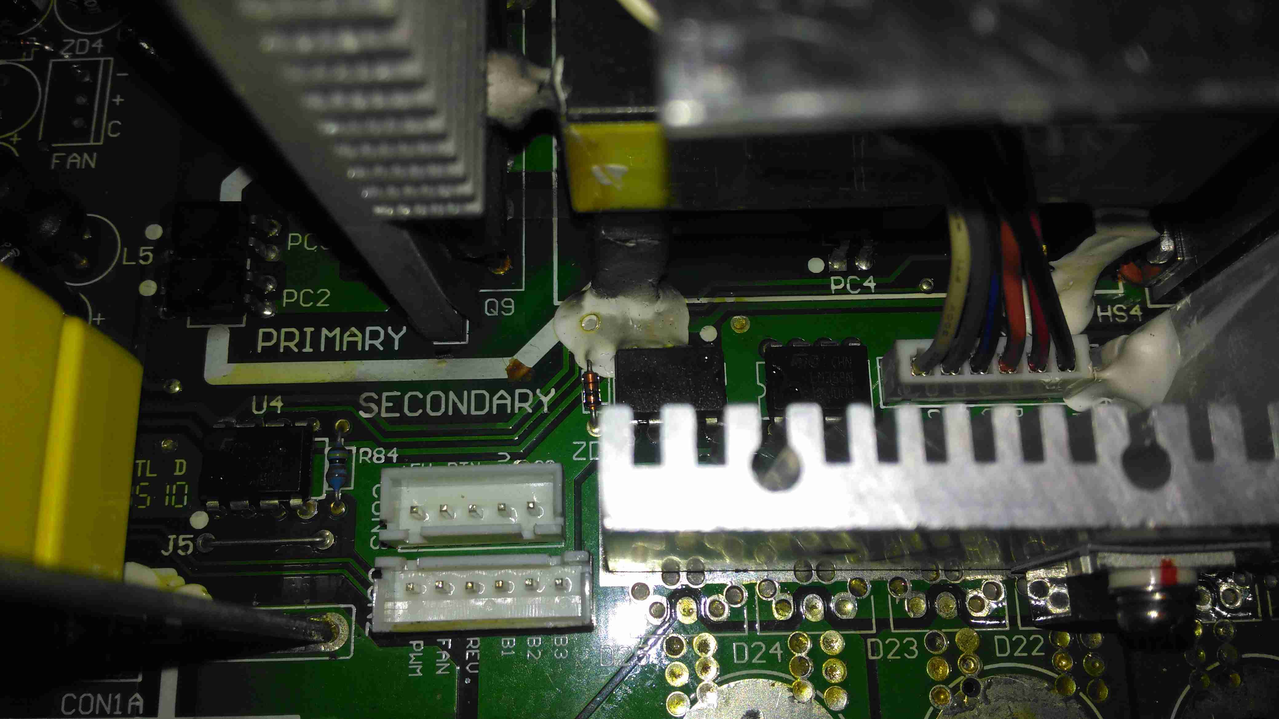
Active PFC Section
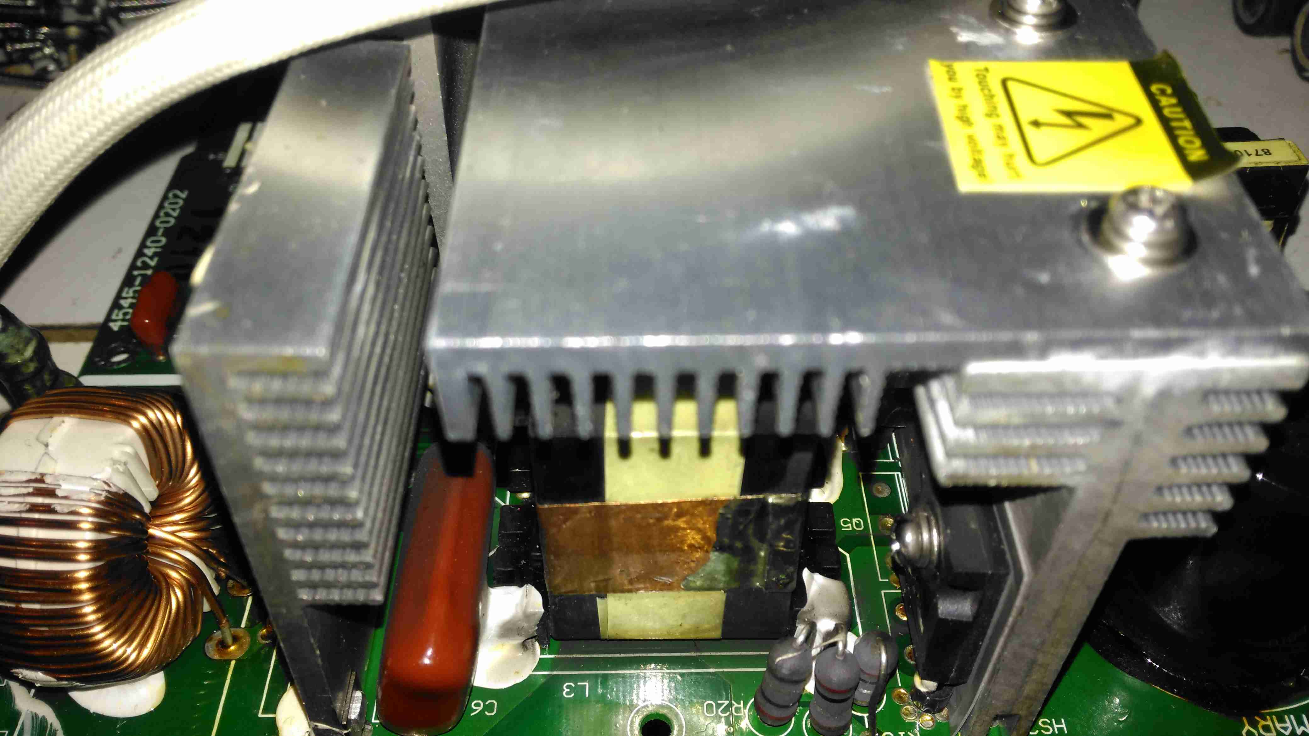
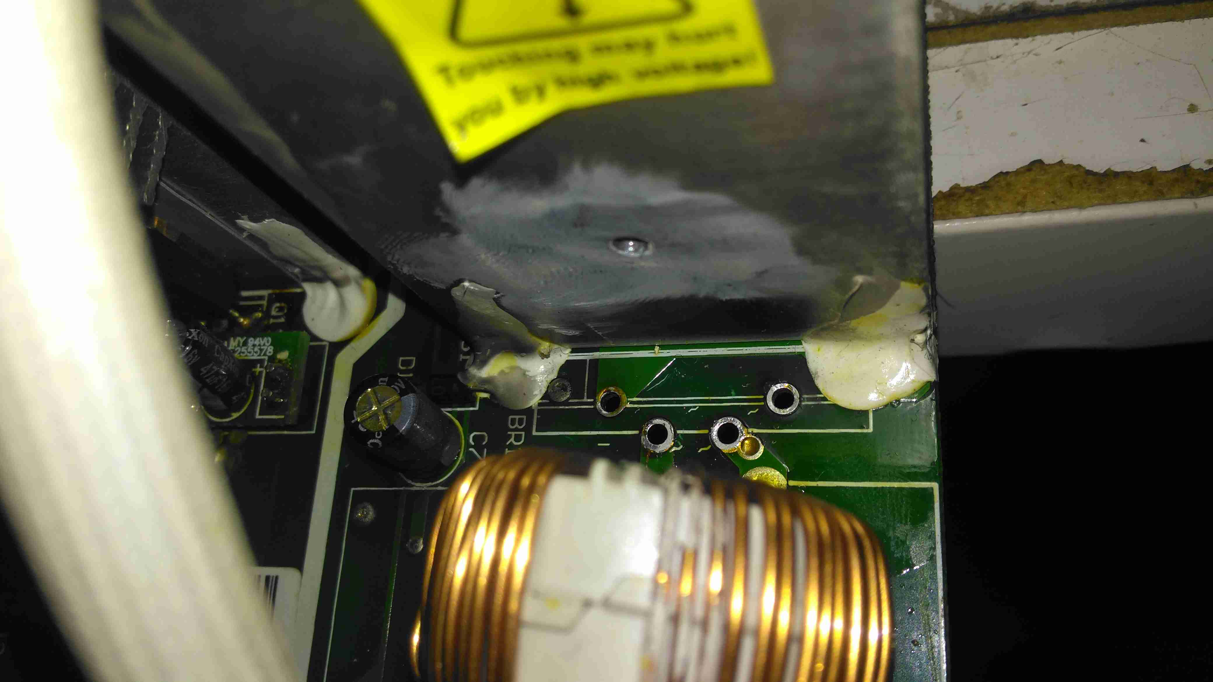
There’s the usual mains input filtering on the left, with the bridge rectifier on it’s heatsink.
Underneath the centre massive heatsinks is the main transformer (not visible here) & active PFC circuit. The device peeking out from underneath is the huge inductor needed for PFC. It’s associated switching MOSFET is to the right.
Logic PSU Section
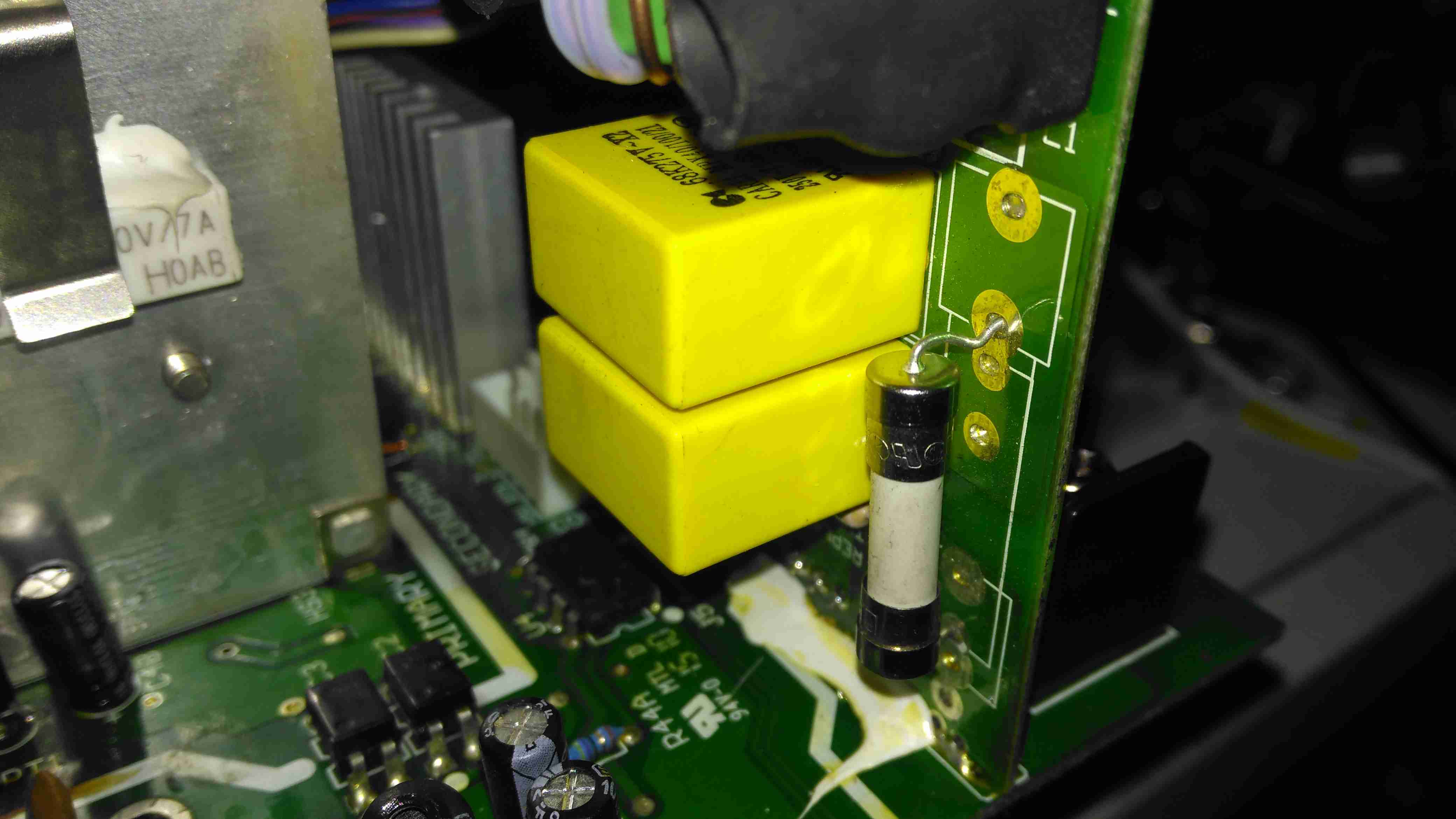
On the other side of the PFC section is the main DC rail filter electrolytic, a 450v 150µF part. Here some evidence of long-term heating can be seen in the adhesive around the base, it’s nearly completely turned black! It’s not a decent brand either, a Chinese CapXon.
The PCB fuse just behind it is in the DC feed to the main switching supply, so the input fuse only protects the filter & Active PFC circuitry. Luckily this fuse didn’t blow during the failure, telling me the fault was earlier in the power chain.
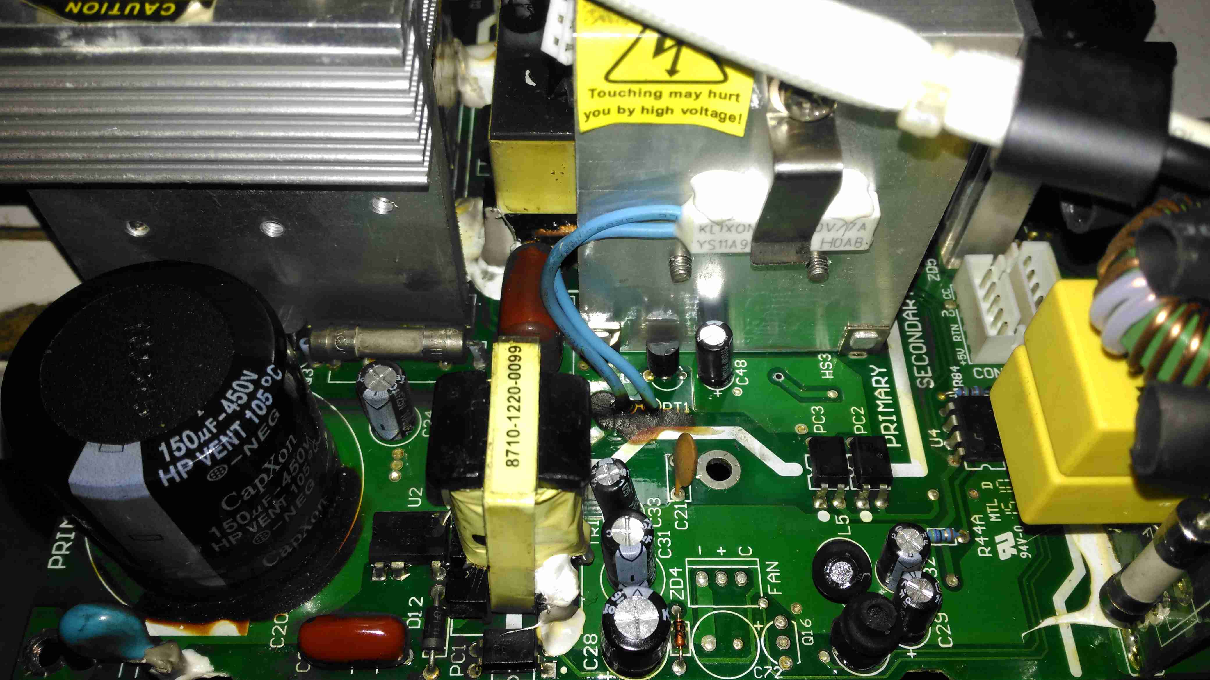
The logic circuits are powered by an independent switching supply in the centre, providing a +5v rail to the microcontroller. The fan header & control components are not populated in this 10A model, but I may end up retrofitting a fan anyway as this unit has always run a little too warm. The entire board is heavily conformal coated on both sides, to help with water resistance associated with being in a marine environment. This has worked well, as there isn’t a single trace of moisture anywhere, only dust from years of use.
There is some thermal protection for the main SMPS switching MOSFETS with the Klixon thermal fuse clipped to the heatsink.
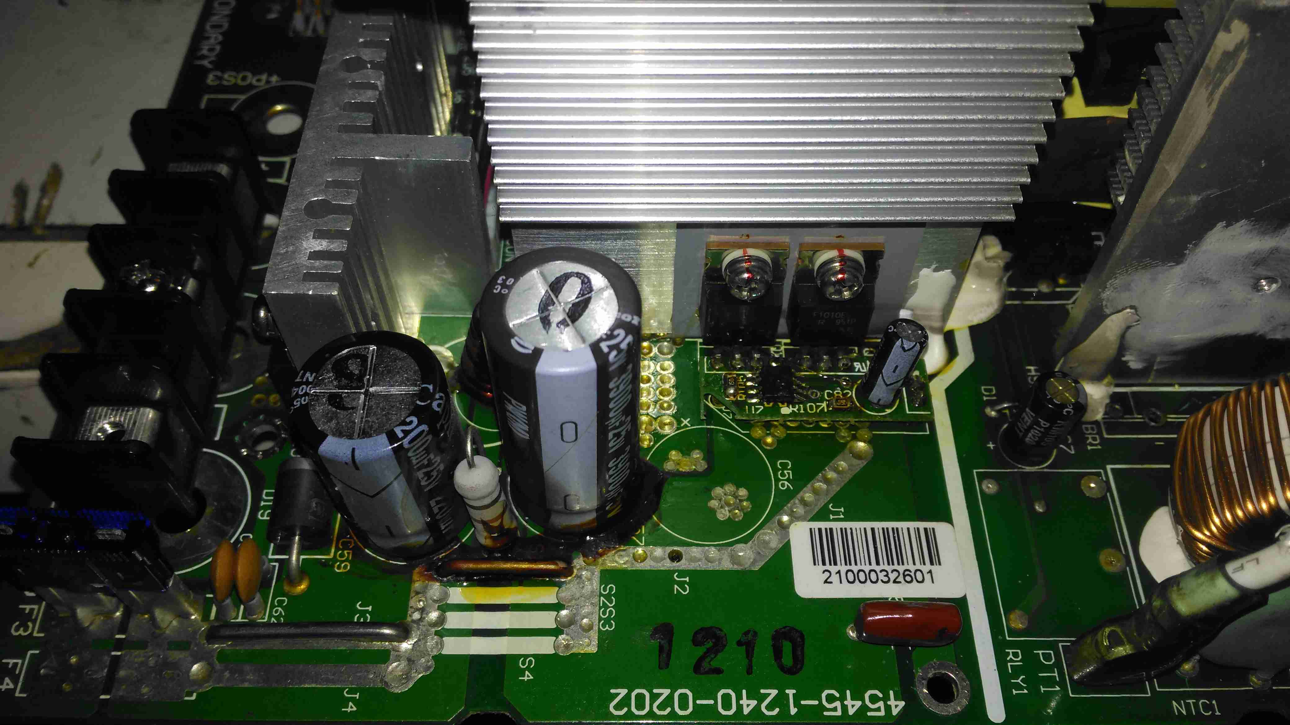
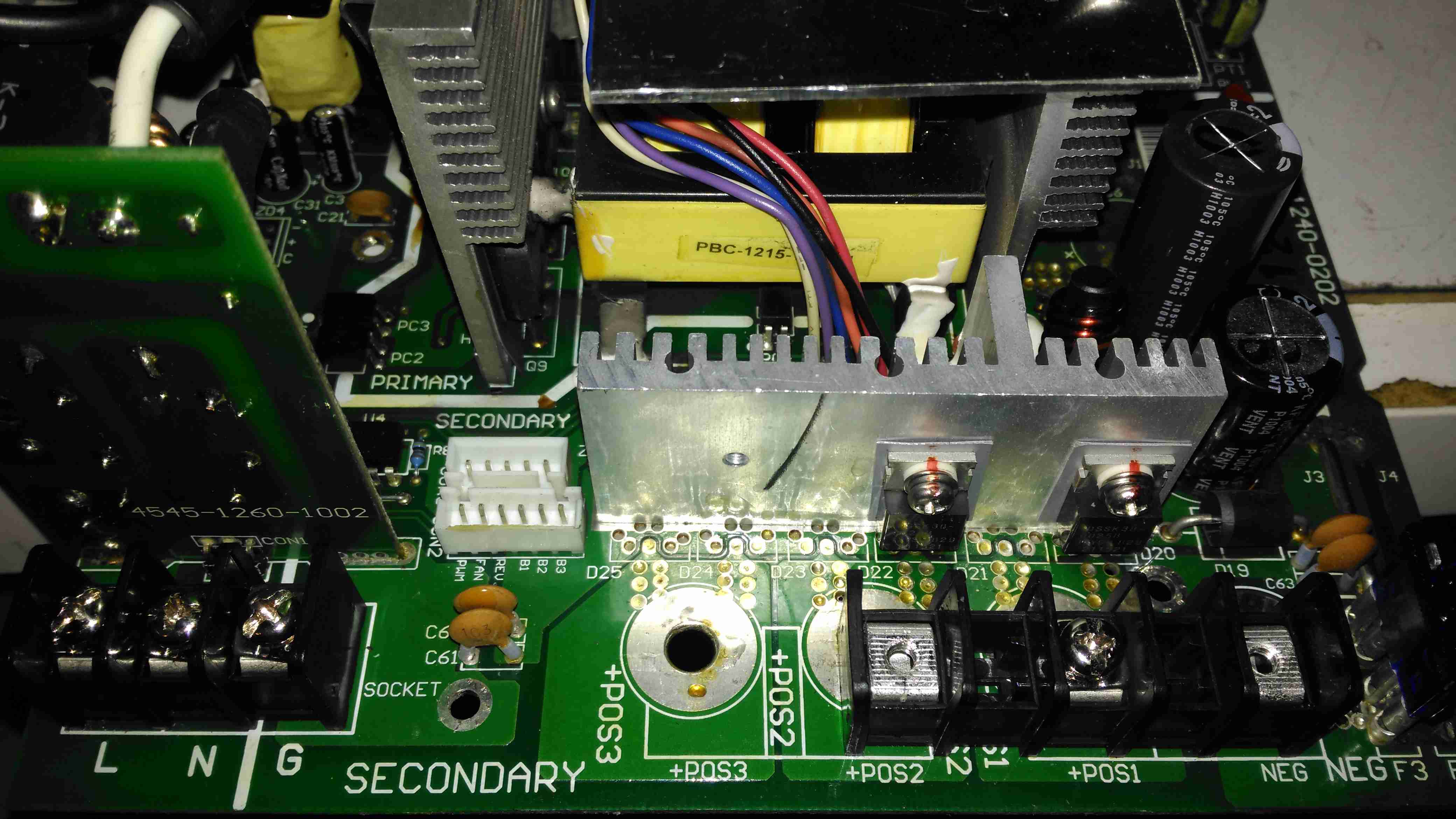
DC Output Section
The DC output rectifiers are on the large heatsink in the centre, with a small bodge board fitted. Due to the heavy conformal coating on the board I can’t get the ID from this small 8-pin IC, but from the fact that the output rectifiers are in fact IRF1010E MOSFETS, rated at 84A a piece, this is an synchronous rectifier controller.
Oddly, the output filter electrolytics are a mix of Nichicon (nice), and CapXon (shite). A bit of penny pinching here, which if a little naff since these chargers are anything but cheap. (£244.80 at the time of writing).
Hiding just behind the electrolytics is a large choke, and a reverse-polarity protection diode, which is wired crowbar-style. Reversing the polarity here will blow the 15A DC bus fuse instantly, and may destroy this diode if it doesn’t blow quick enough.
DC Outputs
Right on the output end are a pair of large Ixys DSSK38 TO220 Dual 20A dual Schottky diodes, isolating the two outputs from each other, a nice margin on these for a 10A charger, since the diodes are paralleled each channel is capable of 40A. This prevents one bank discharging into another & allows the charger logic to monitor the voltages individually. The only issue here is the 400mV drop of these diodes introduce a little bit of inefficiency. To increase current capacity of the PCB, the aluminium heatsink is being used as the main positive busbar. From the sizing of the power components here, I would think that the same PCB & component load is used for all the chargers up to 40A, since both the PFC inductor & main power transformer are massive for a 10A output. There are unpopulated output components on this low-end model, to reduce the cost since they aren’t needed.
Front Panel Control Connections
A trio of headers connect all the control & sense signals to the front panel PCB, which contains all the control logic. This unit is sensing all output voltages, output current & PSU rail voltages.
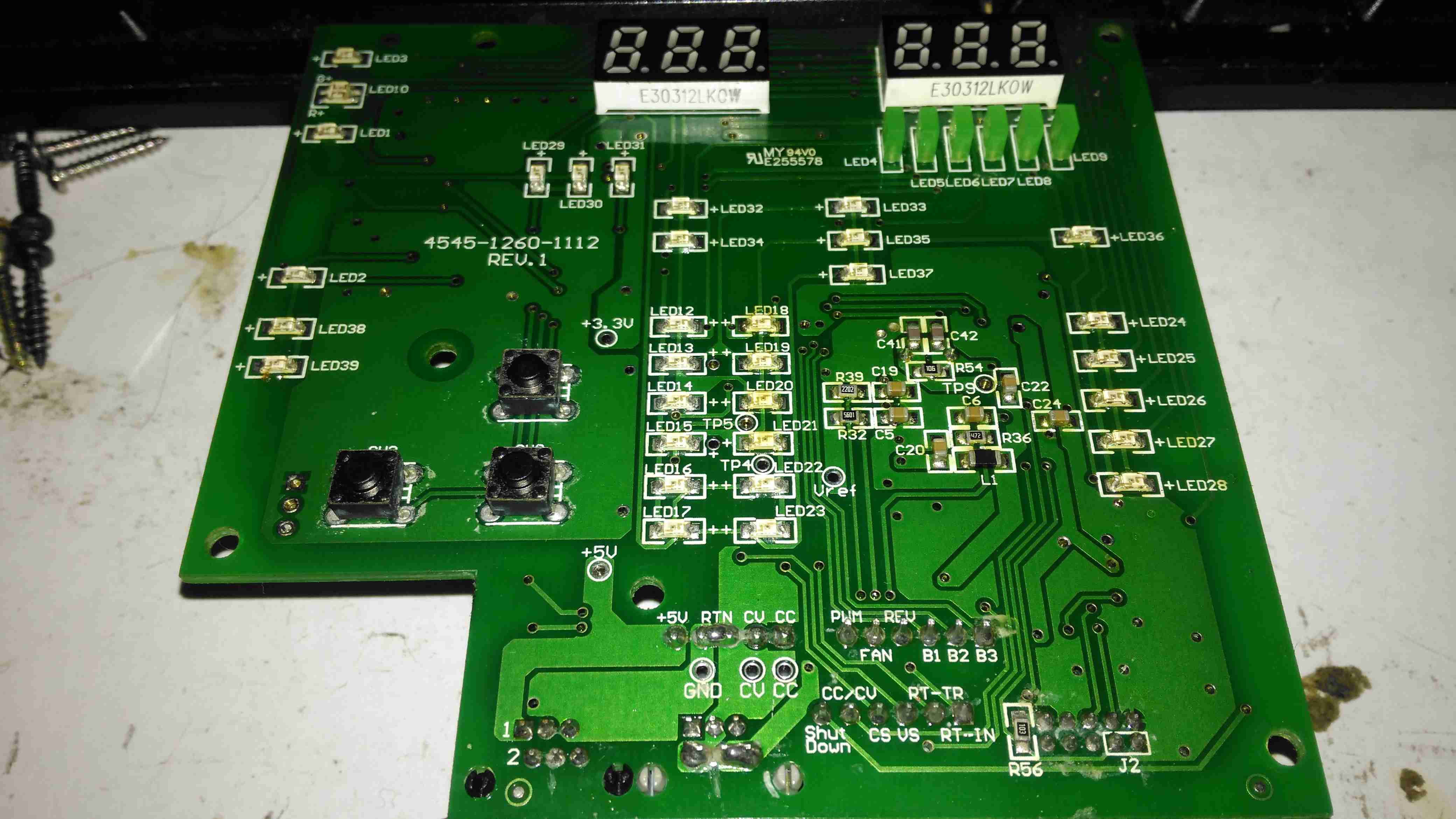
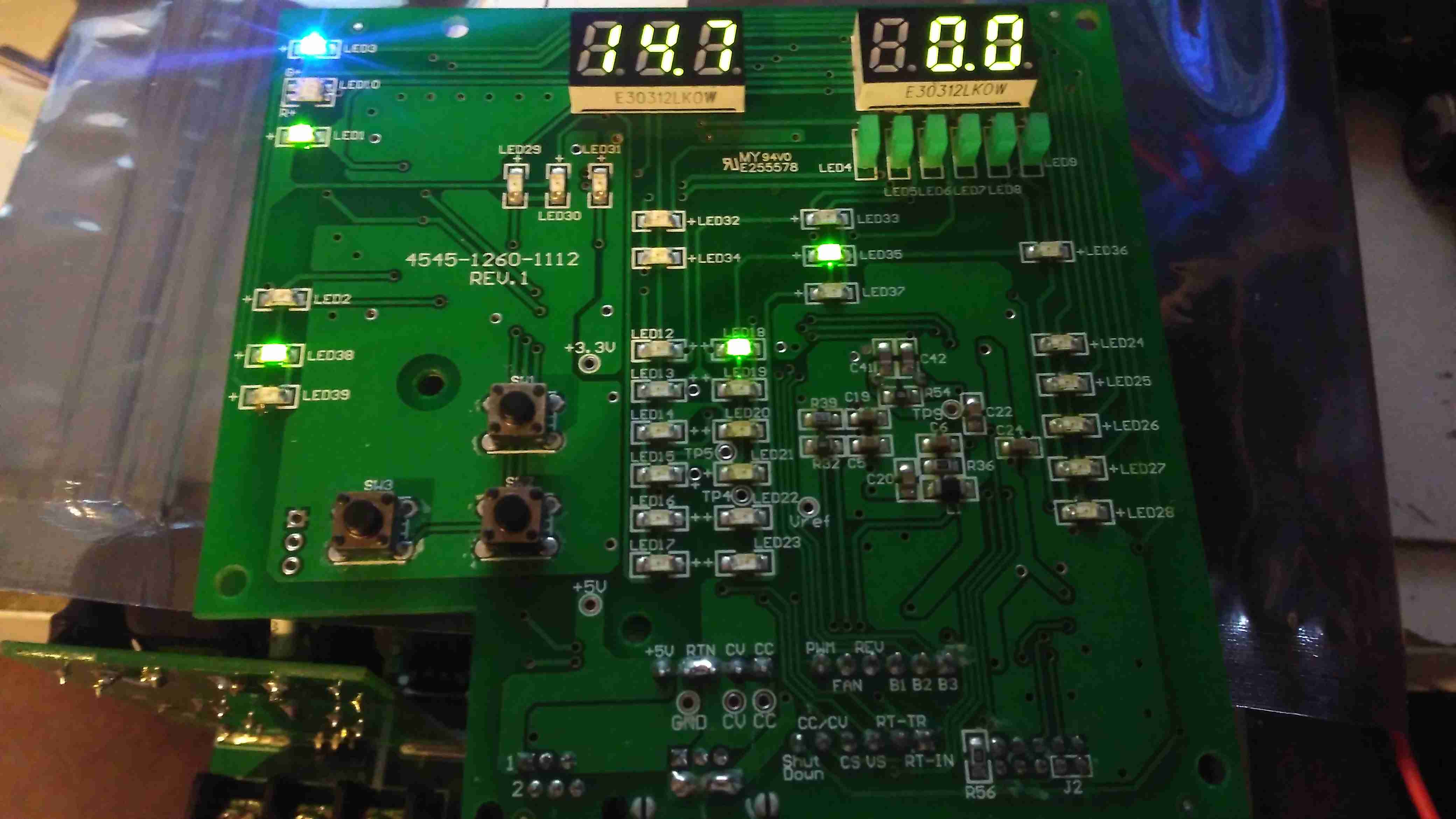
Front Panel LEDs
The front panel is stuffed with LEDs & 7-segment displays to show the current mode, charging voltage & current. There’s 2 tactile switches for adjustments.
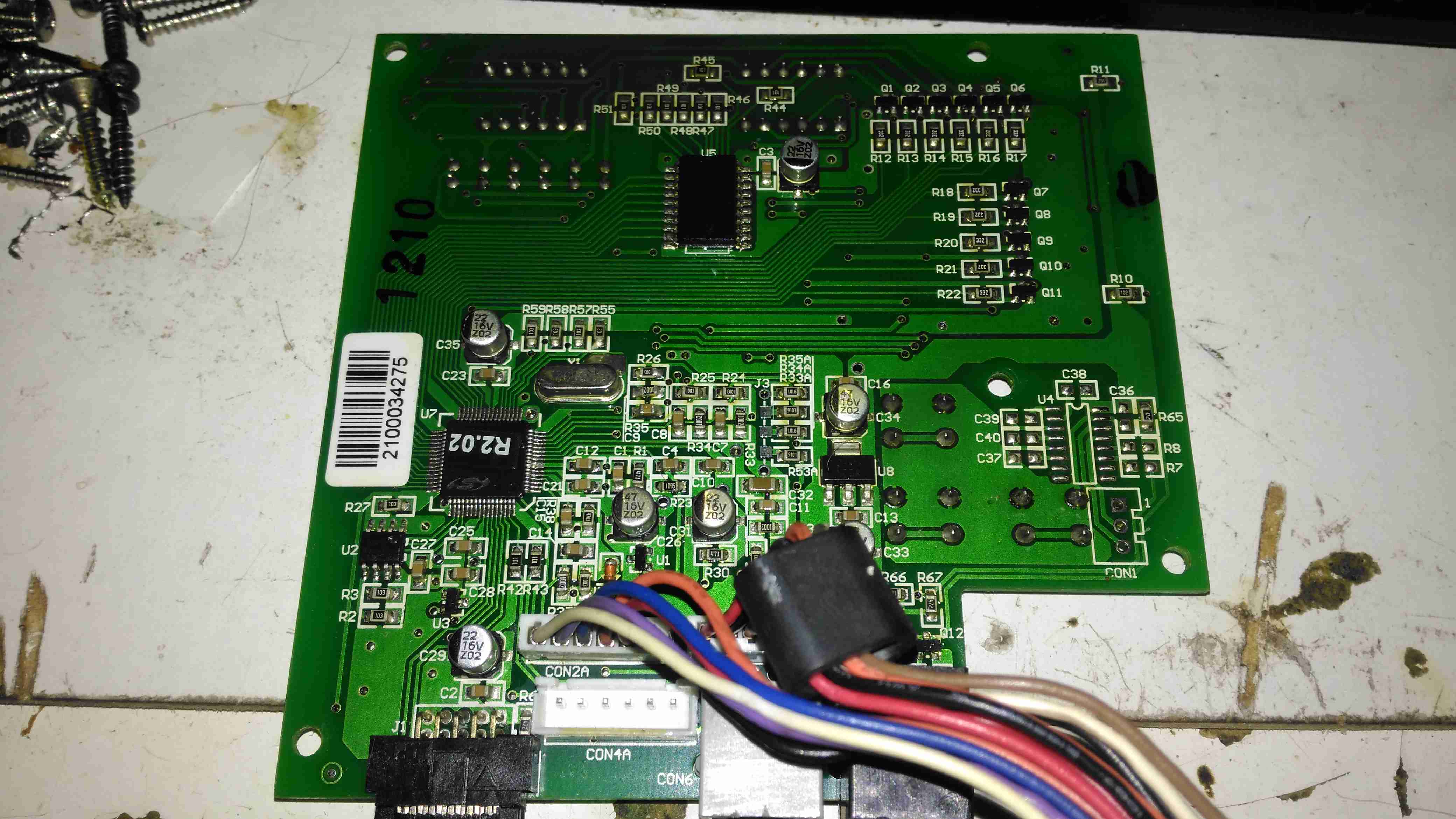
Front Panel Reverse
The reverse of the board has the main microcontroller – again identifying this is impossible due to the heavy conformal coat. The LEDs are being driven through a 74HC245D CMOS Octal Bus Transceiver.
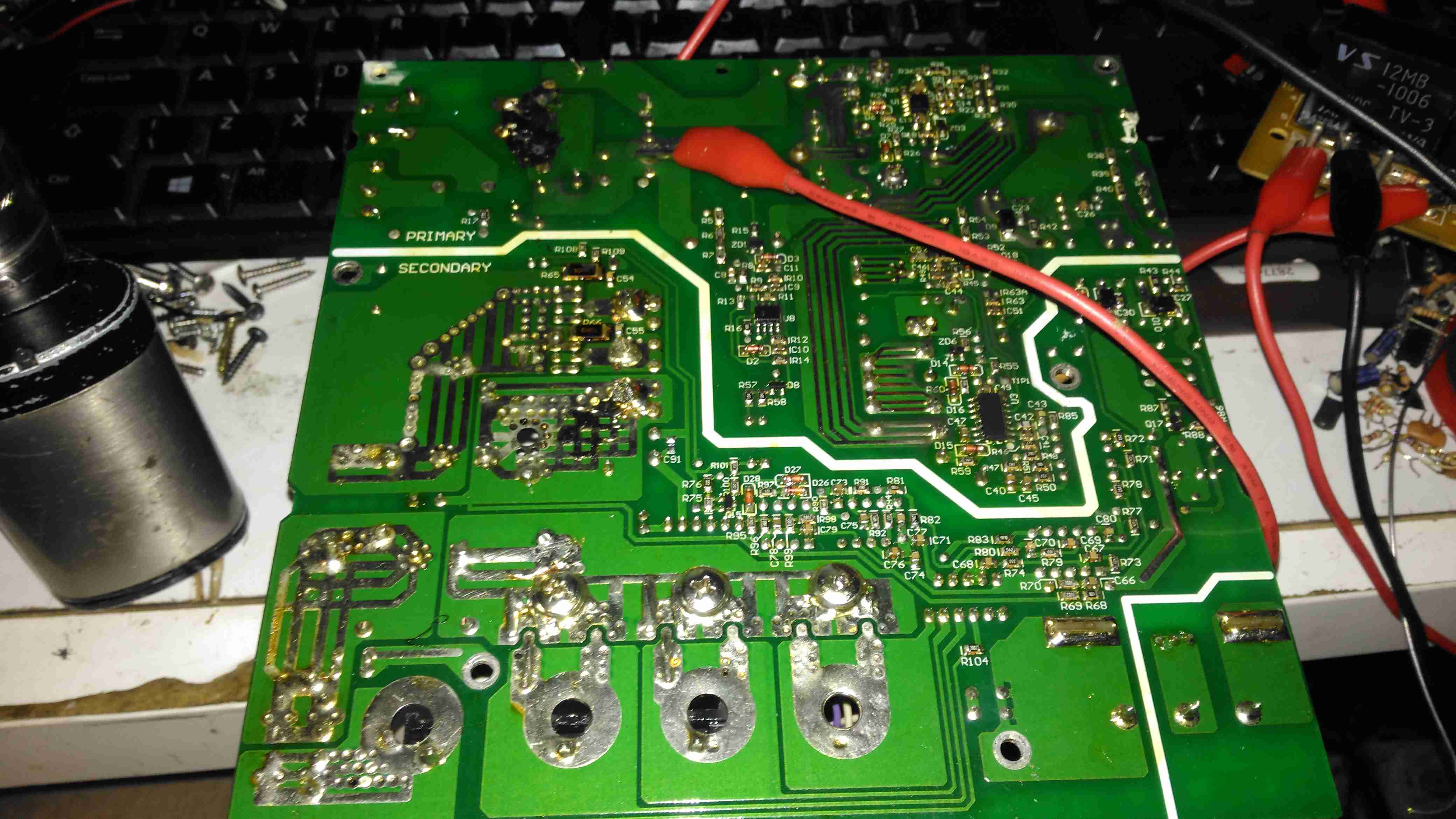
Now on to the repair! I’m not particularly impressed with only getting 4 years from this unit, they are very expensive as already mentioned, so I would expect a longer lifespan. The input fuse had blown in this case, leaving me with a totally dead charger. A quick multimeter test on the input stage of the unit showed a dead short – the main AC input bridge rectifier has gone short circuit.
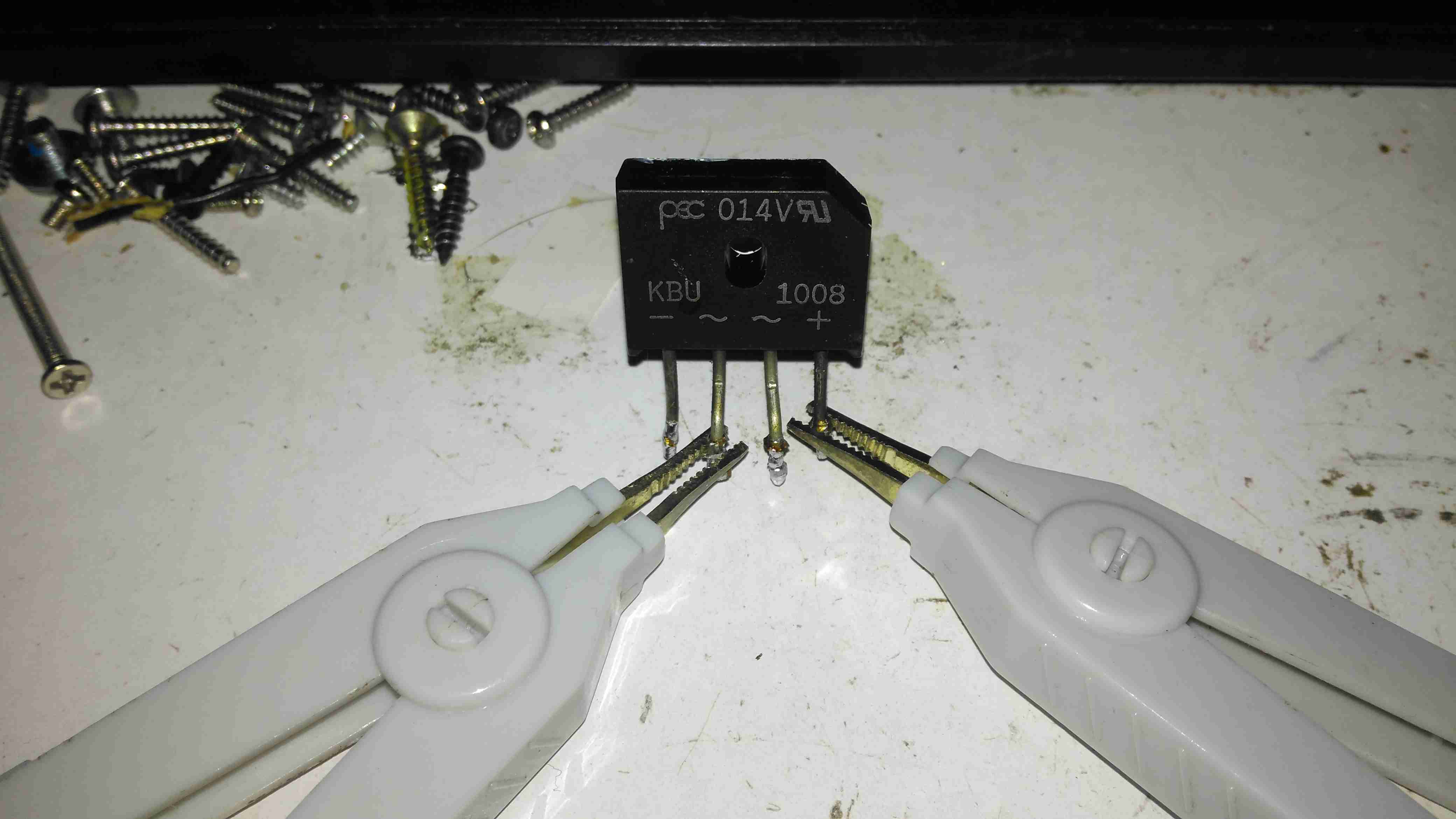
Bridge Rectifier Removed
Here the defective bridge has been desoldered from the board. It’s a KBU1008 10A 800v part. Once this was removed I confirmed there was no longer an input short, on either the AC side or the DC output side to the PFC circuit.
Testing The Rectifier
Time to stick the desoldered bridge on the milliohm meter & see how badly it has failed.
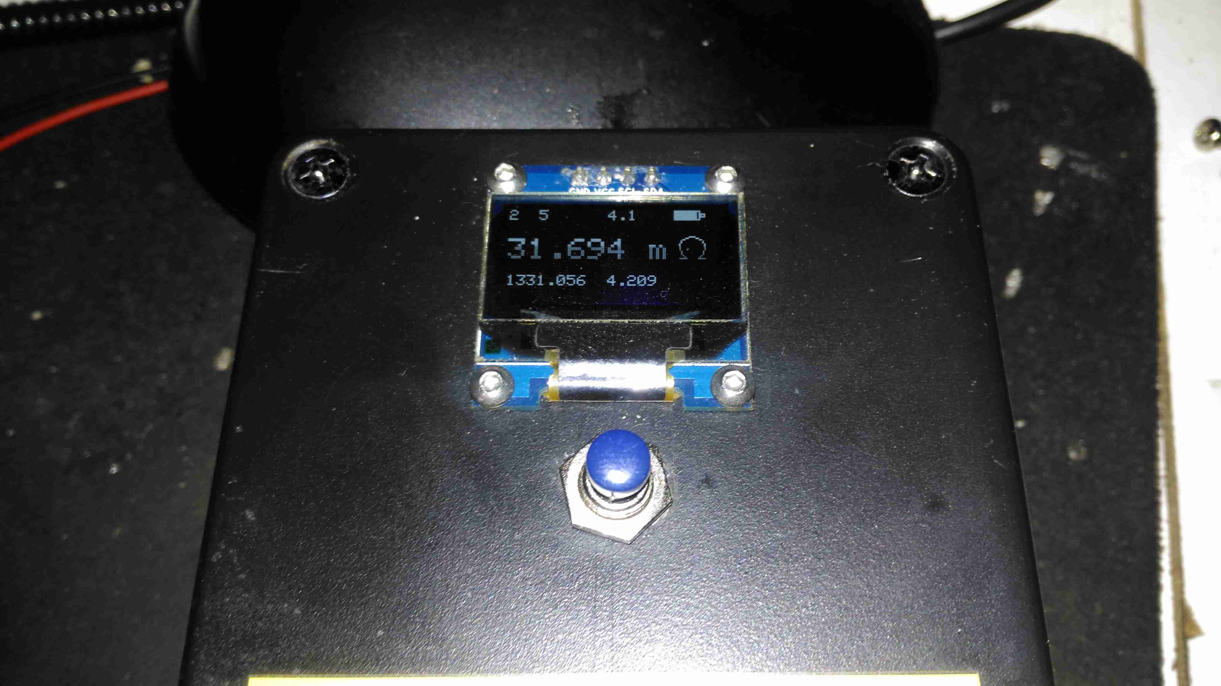
Yep, Definitely Shorted
I’d say 31mΩ would qualify as a short. It’s no wonder the 4A input fuse blew instantly. There is no sign of excessive heat around the rectifier, so I’m not sure why this would have failed, it’s certainly over-rated for the 10A charger.
Testing Without Rectifier
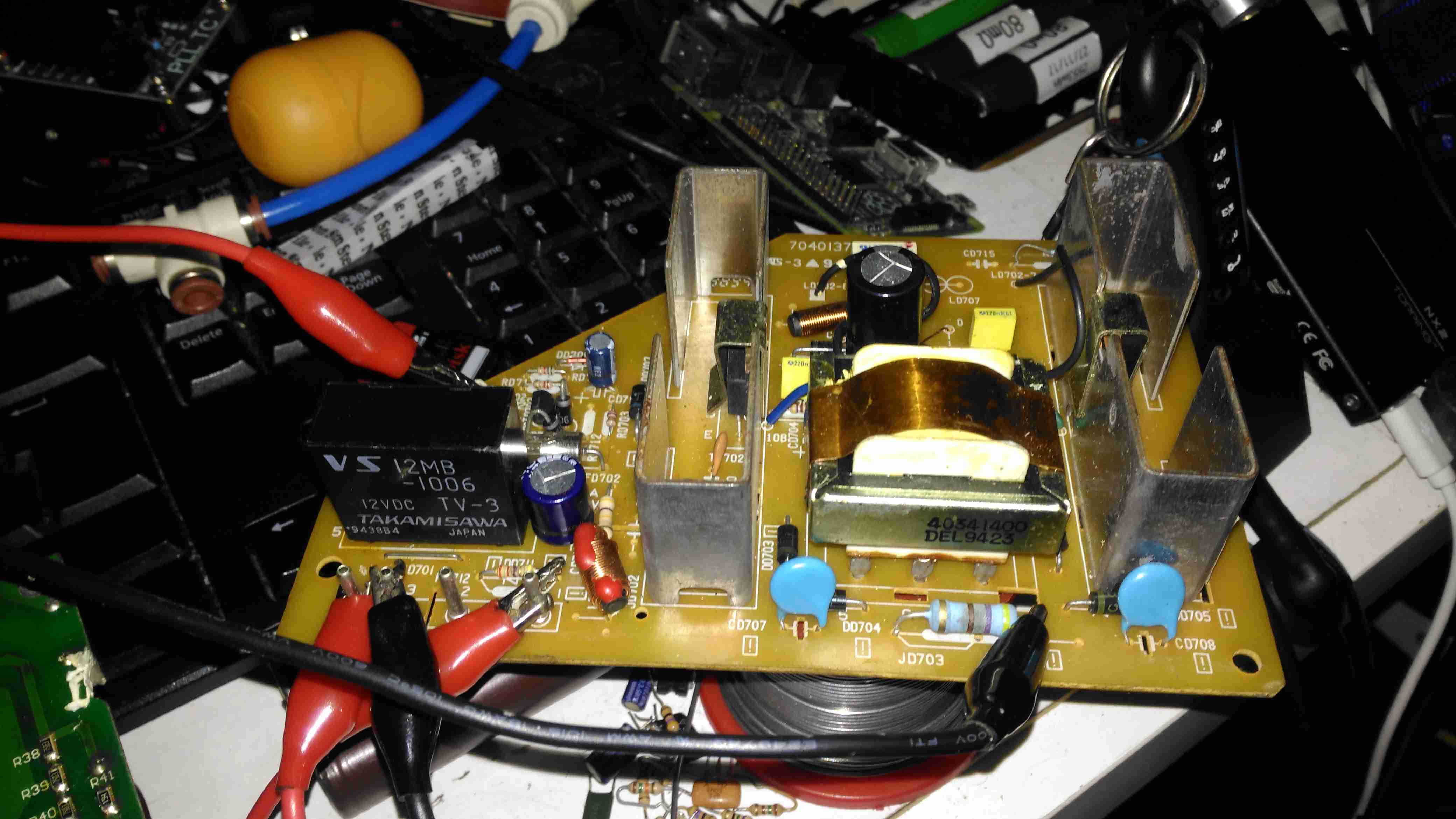
Now the defective diode bridge has been removed from the circuit, it’s time to apply some controlled power to see if anything else has failed. For this I used a module from one of my previous teardowns – the inverter from a portable TV.
Test Inverter
This neat little unit outputs 330v DC at a few dozen watts, plenty enough to power up the charger with a small load for testing purposes. The charger does pull the voltage of this converter down significantly, to about 100v, but it still provides just enough to get things going.
It’s Alive!
After applying some direct DC power to the input, it’s ALIVE! Certainly makes a change from the usual SMPS failures I come across, where a single component causes a chain reaction that writes off everything.
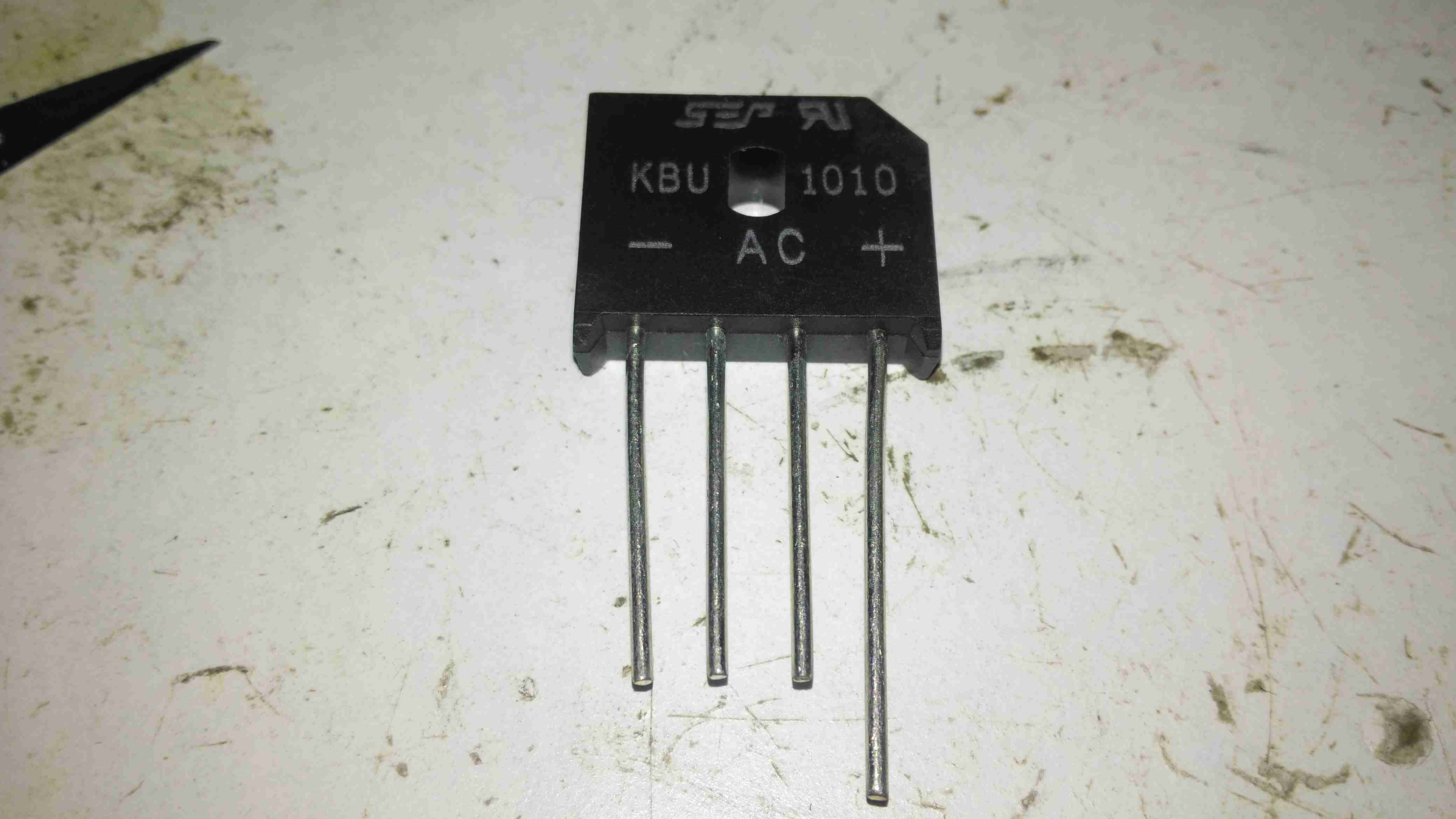
Replacement Rectifier
Unfortunately I couldn’t find the exact same rectifier to replace the shorted one, so I had to go for the KBU1010, which is rated for 1000v instead of 800v, but the Vf rating (Forward Voltage), is the same, so it won’t dissipate any more power.
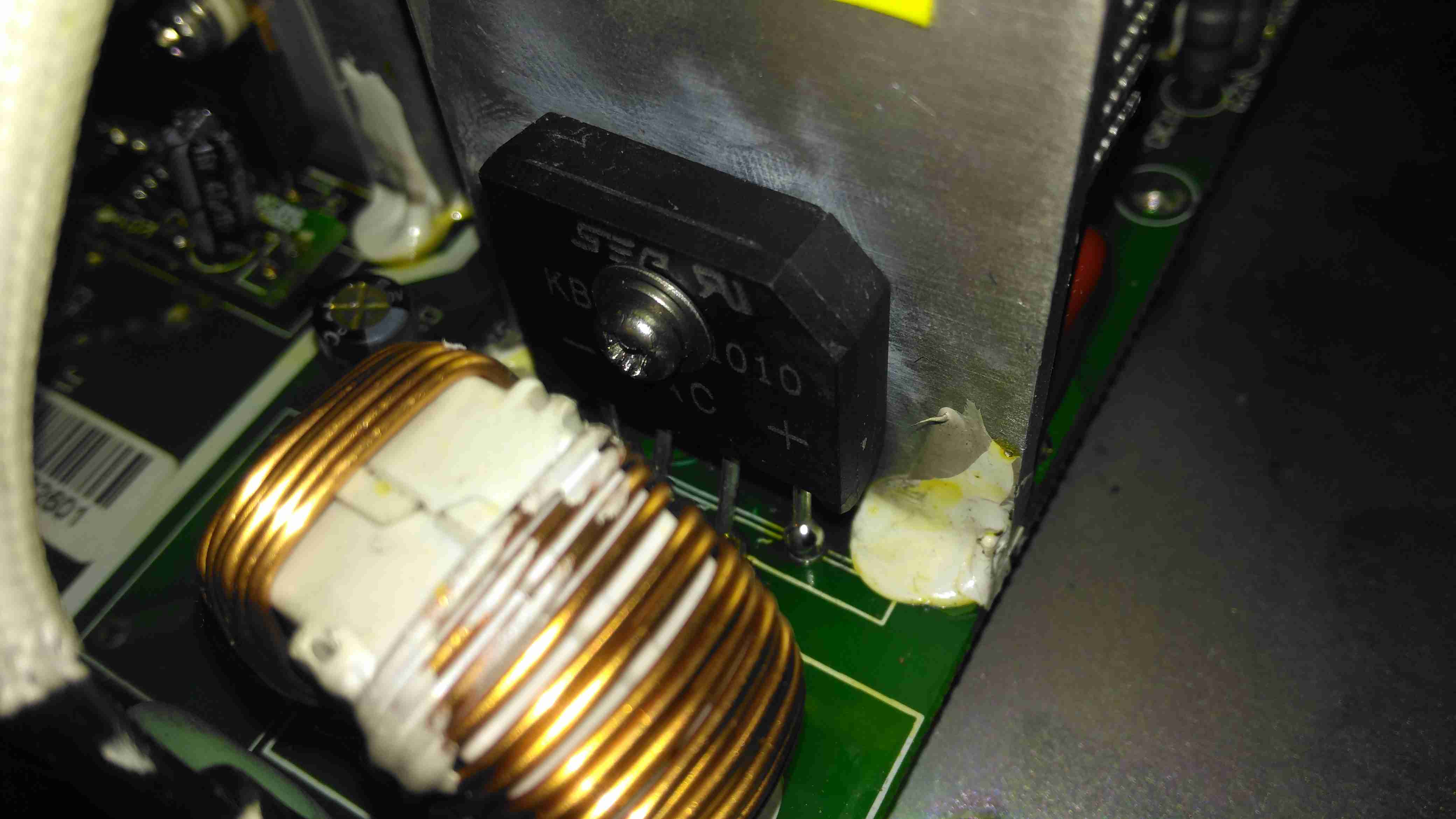
Soldered In
Here’s the new rectifier soldered into place on the PCB & bolted to it’s heatsink, with some decent thermal compound in between.
Input Board
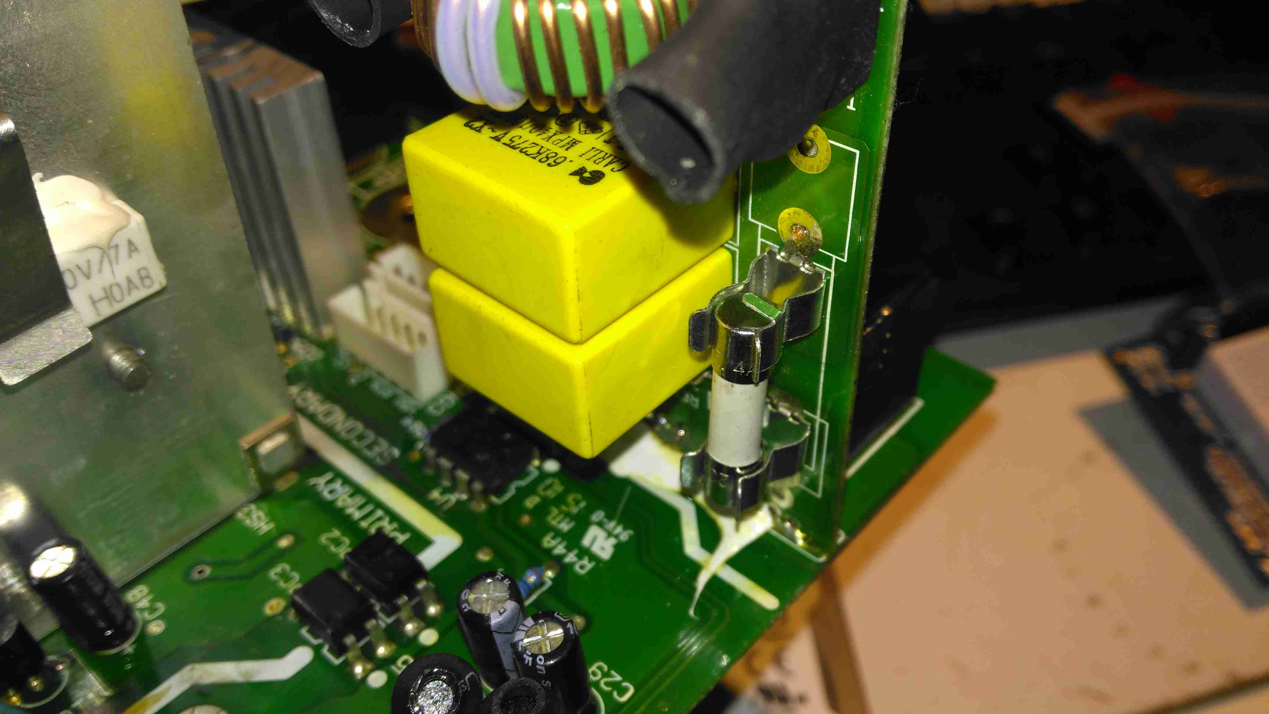
Here is the factory fuse, a soldered in device. I’ll be replacing this with standard clips for 20x5mm fuses to make replacement in the future easier, the required hole pattern in the PCB is already present. Most of the mains input filtering is also on this little daughterboard.
Fuse Replaced
Now the fuse has been replaced with a standard one, which is much more easily replaceable. This fuse shouldn’t blow however, unless another fault develops.
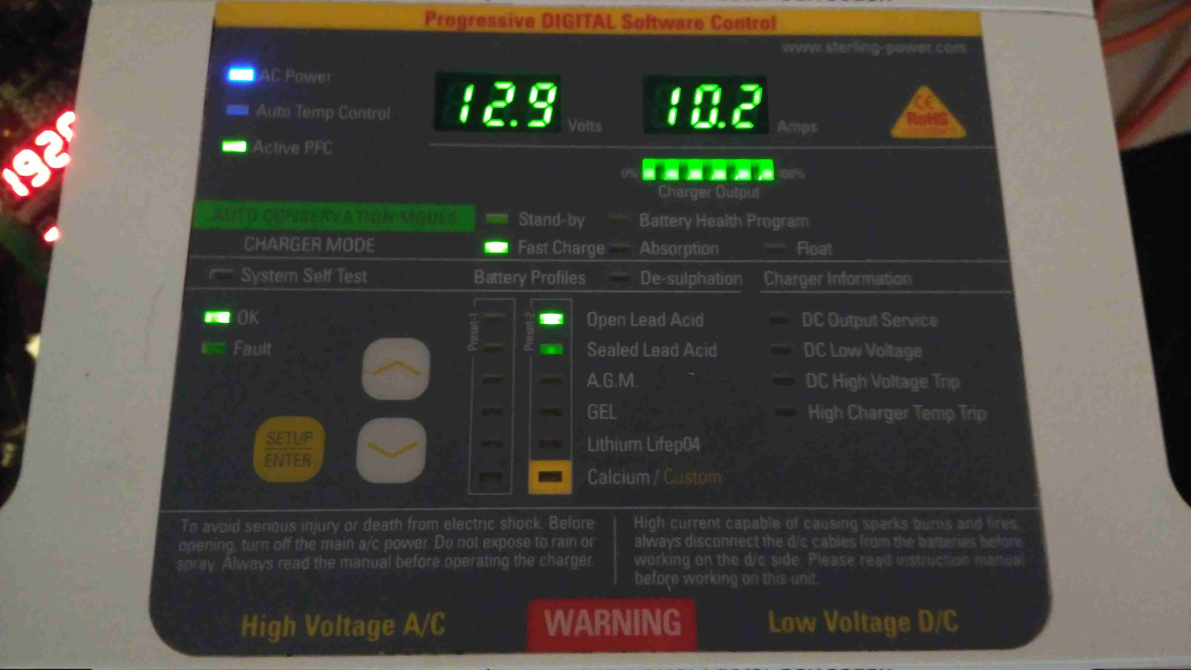
Full Load Test
Now everything is back together, a full load test charging a 200Ah 12v battery for a few hours will tell me if the fix is good. This charger won’t be going back into service onboard the boat, it’s being replaced anyway with a new 50A charger, to better suit the larger loads we have now. It won’t be a Sterling though, as they are far too expensive. I’ll report back if anything fails!
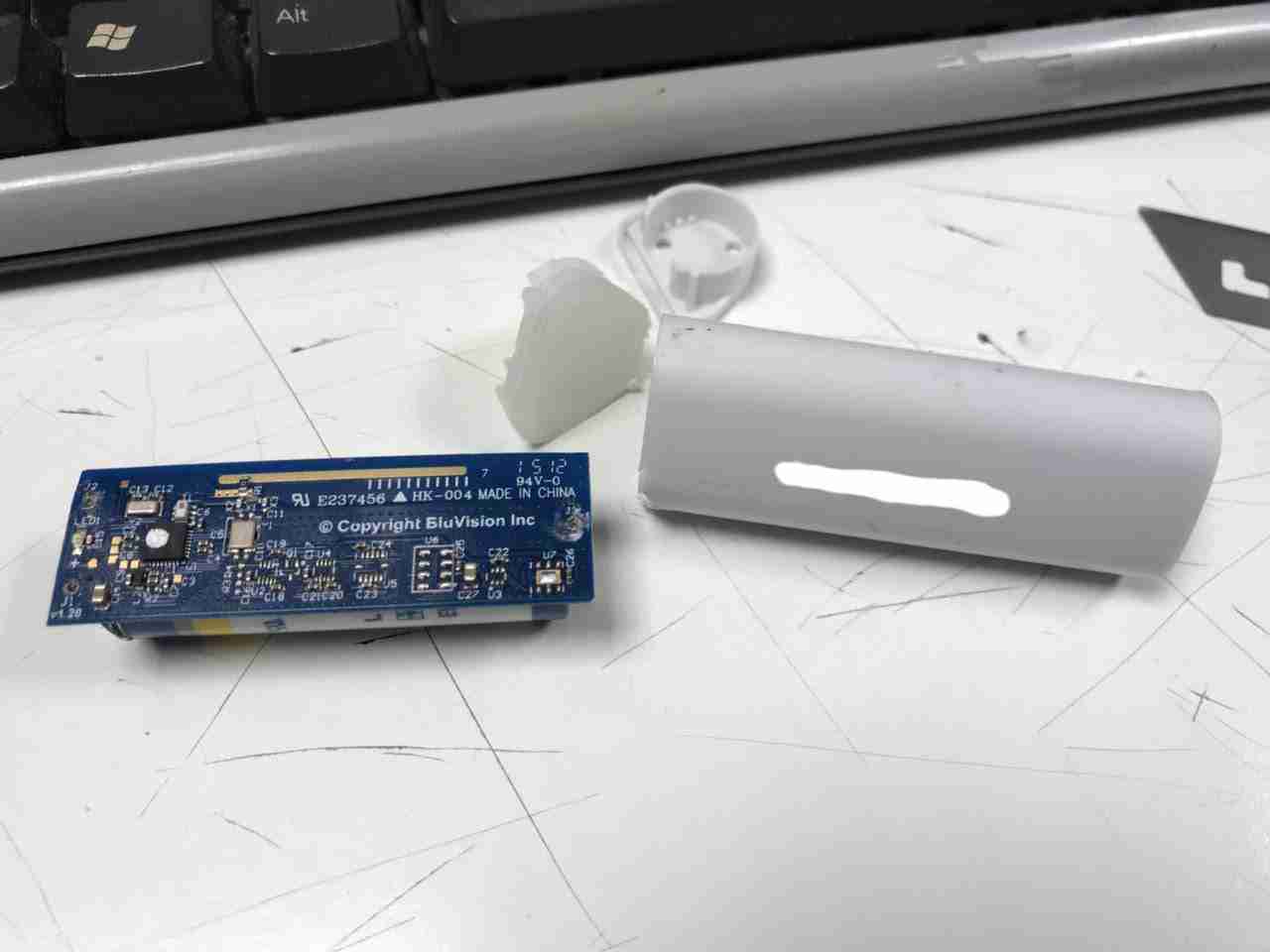
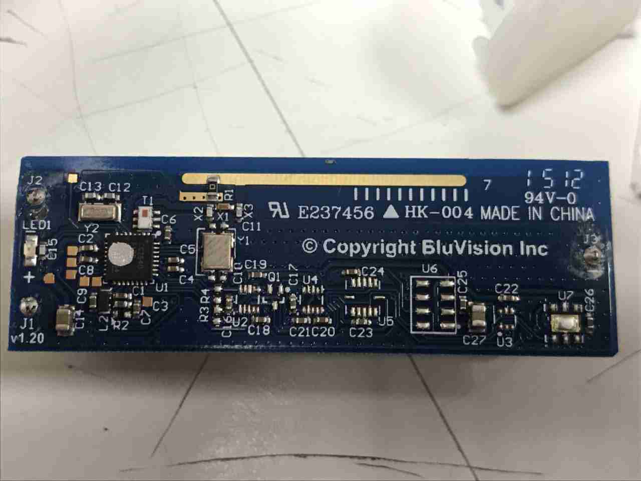
These photos were sent over to me by a friend, an interesting piece of tech that’s used in the retail industry. This is a BluVision BLE Beacon, which as far as I can tell is used to provide some automated customer assistance. From their website it seems they can also be used for high-price asset protection & tracking. These units don’t appear to be serviceable, being completely sealed & only having a primary cell. I’m not sure what they cost but it seems to be an expensive way to contact clients with adverts etc.
Component Side
There’s not much populated on this PCB, the main component here is the CC2640 SimpleLink ultra-low-power wireless microcontroller for Bluetooth Low Energy. It’s a fairly powerful CPU, with an ARM Cortex M3 core, 129KB of flash & up to 48MHz clock speed. There’s a couple of crystals, one of which is most likely a 32,768kHz low-power sleep watch crystal, while the other will be the full clock frequency used while it’s operating. Unfortunately I can’t make the markings out from the photos. There doesn’t appear to be any significant power supply components, so this must be running direct from the battery underneath.
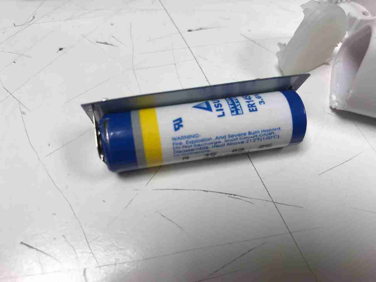
2.2Ah 3.6v Lithium Cell
The other side of the PCB has a single primary lithium cell, rated at 3.6v, 2.2Ah. The factory spec sheet specifies a 2.2 year life at 0dBm TX Power, Running 24/7, 100ms advertisement rate.
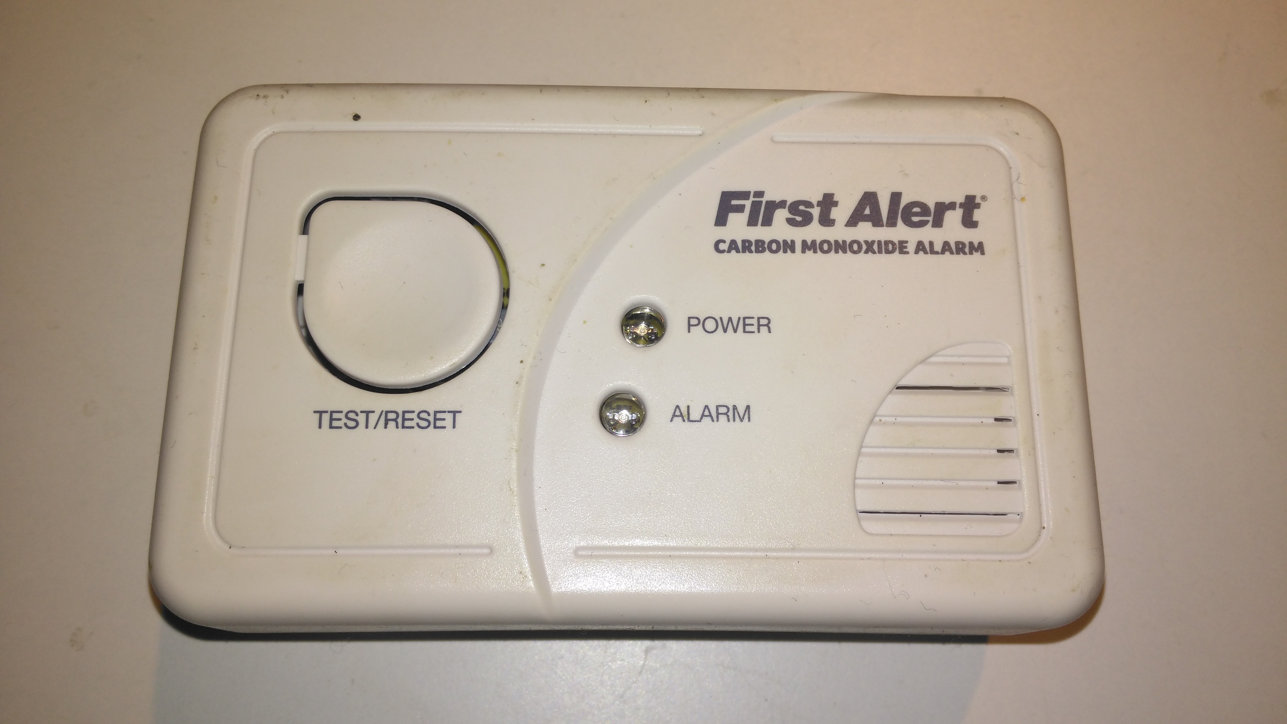
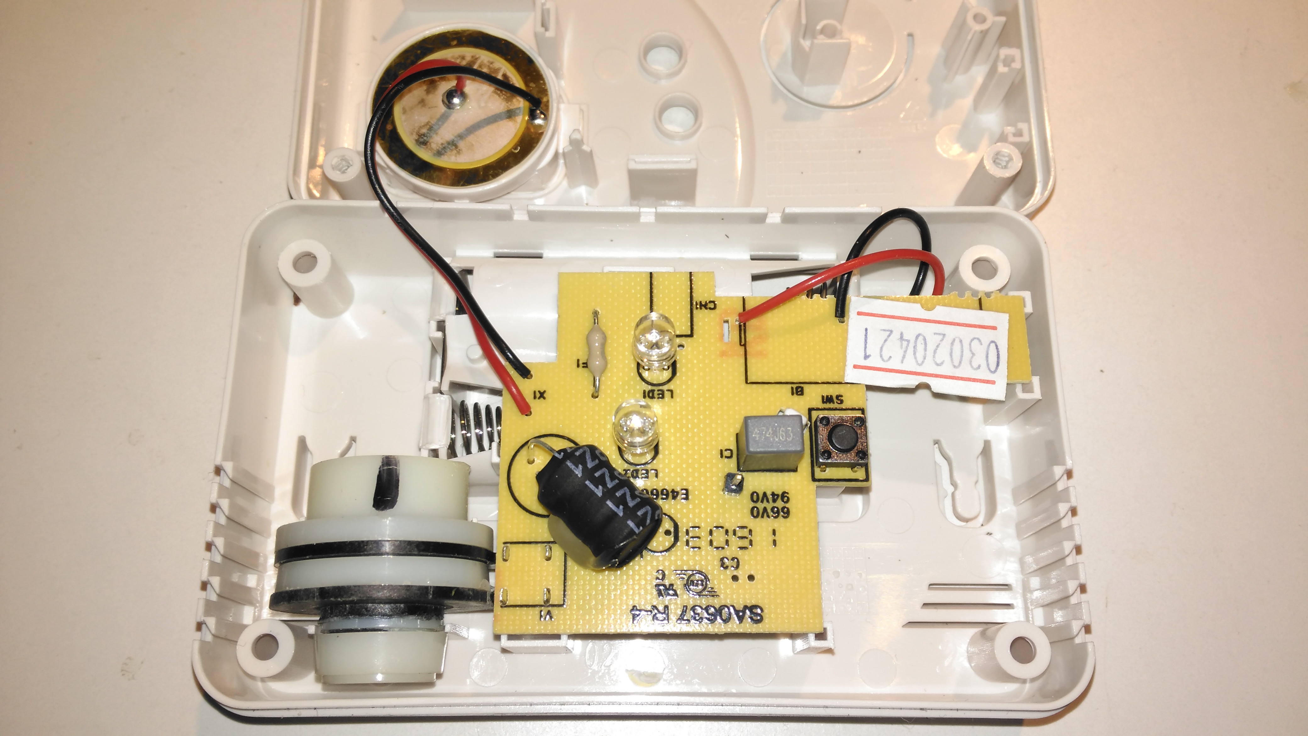
Here’s another domestic CO Alarm, this one a cheaper build than the FireAngel ones usually use, these don’t have a display with the current CO PPM reading, just a couple of LEDs for status & Alarm.
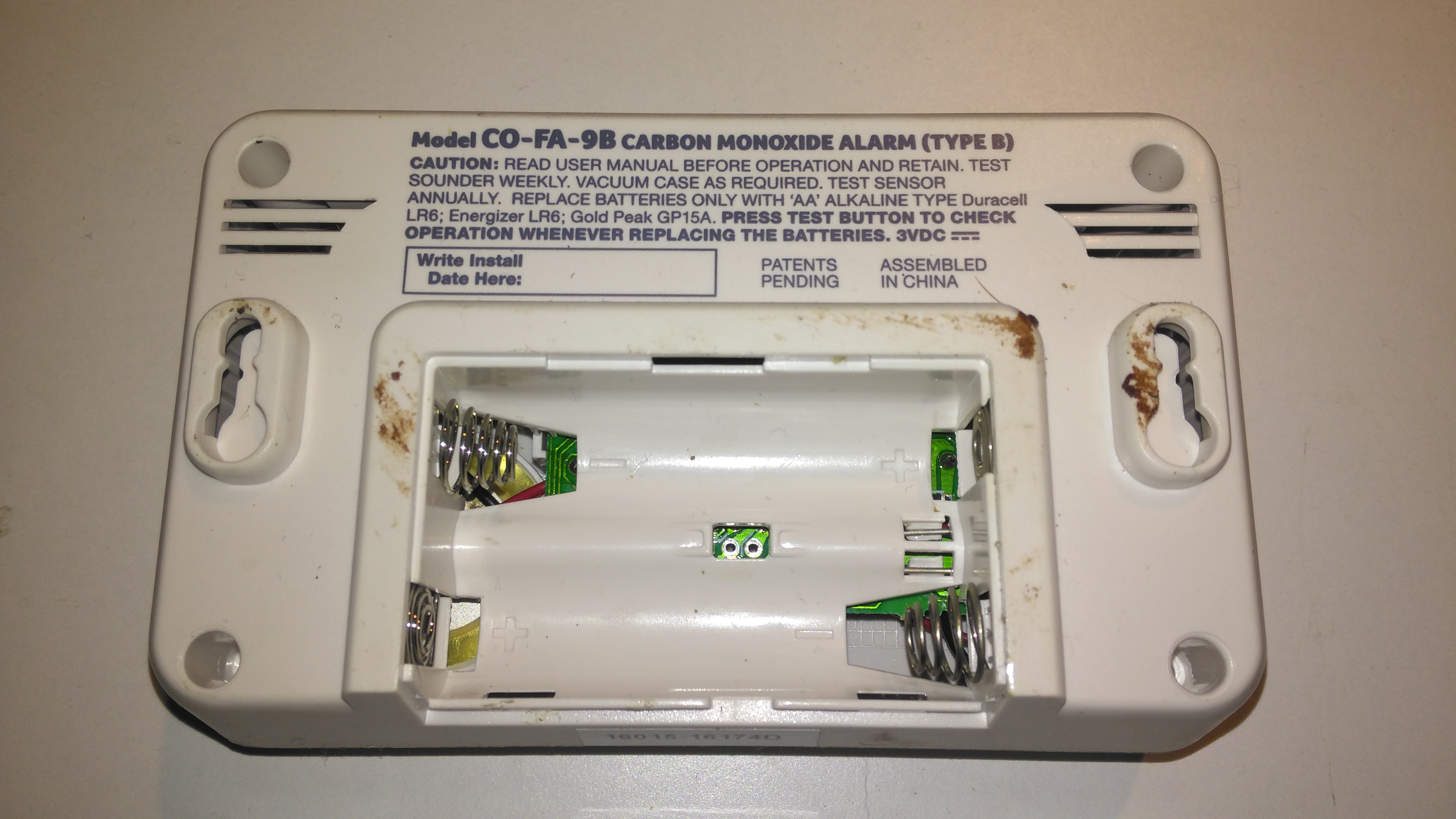
Rear
This alarm also doesn’t have the 10-year lithium cell for power, taking AA cells instead. The alarm does have the usual low battery alert bleeps common with smoke alarms though, so you’ll get a fair reminder to replace them.
Internals
Not much at all on the inside. The CO sensor cell is the same one as used in the FireAngel alarms, I have never managed to find who manufactures these sensors, or a datasheet for them unfortunately.
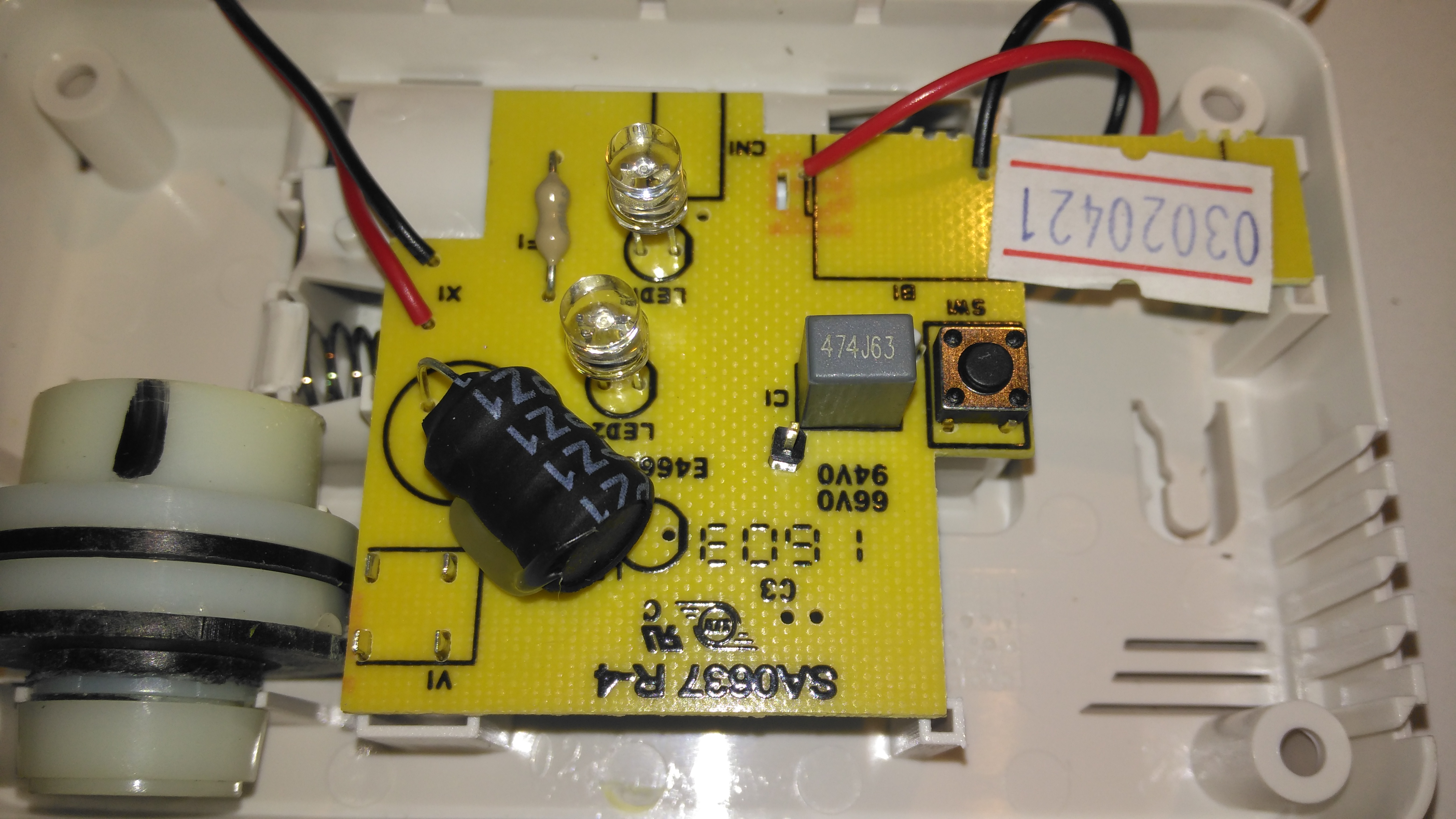
PCB Top
The top of the single sided PCB has the transformer for driving the Piezo sounder, the LEDs & the test button.
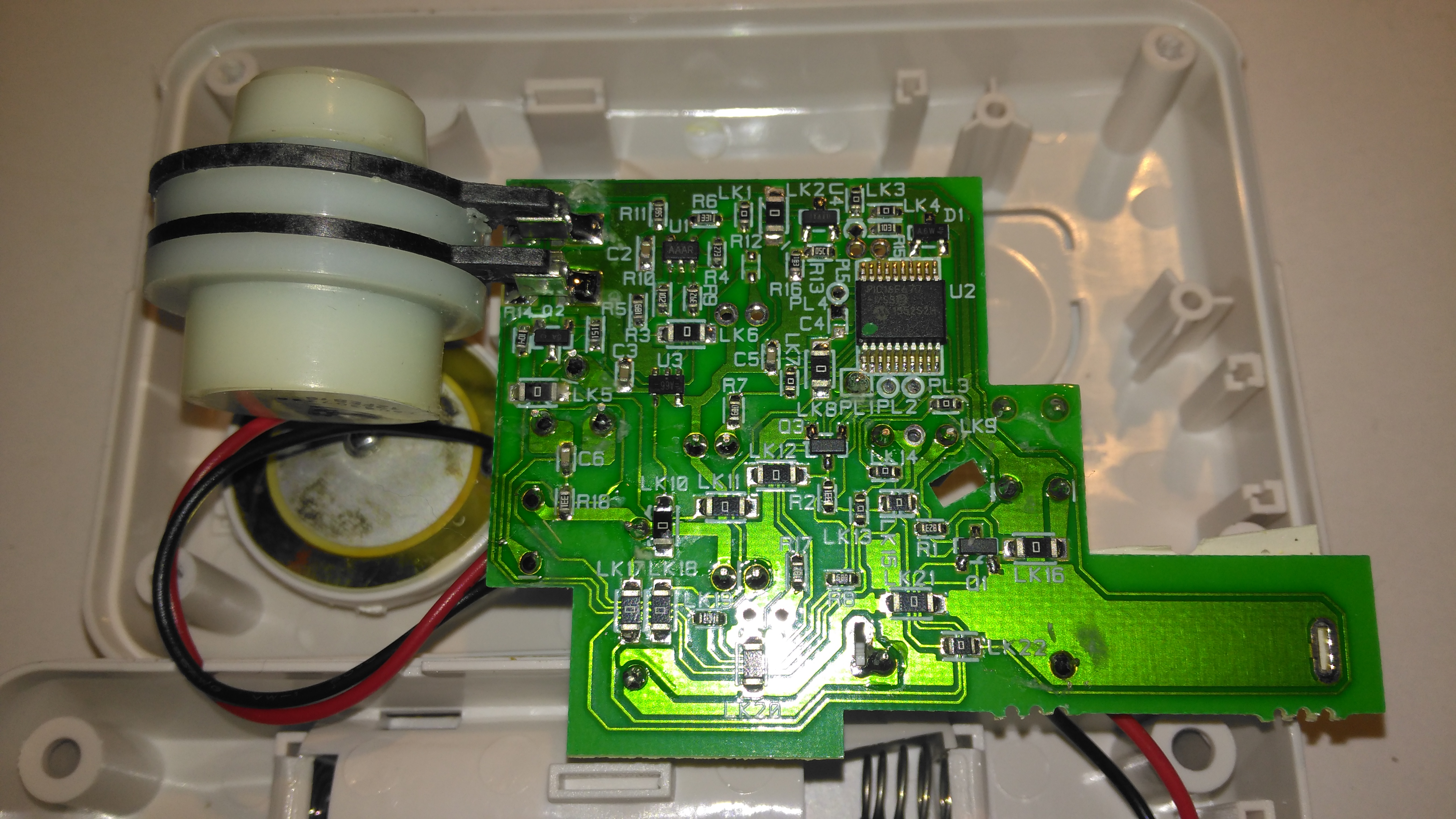
PCB Bottom
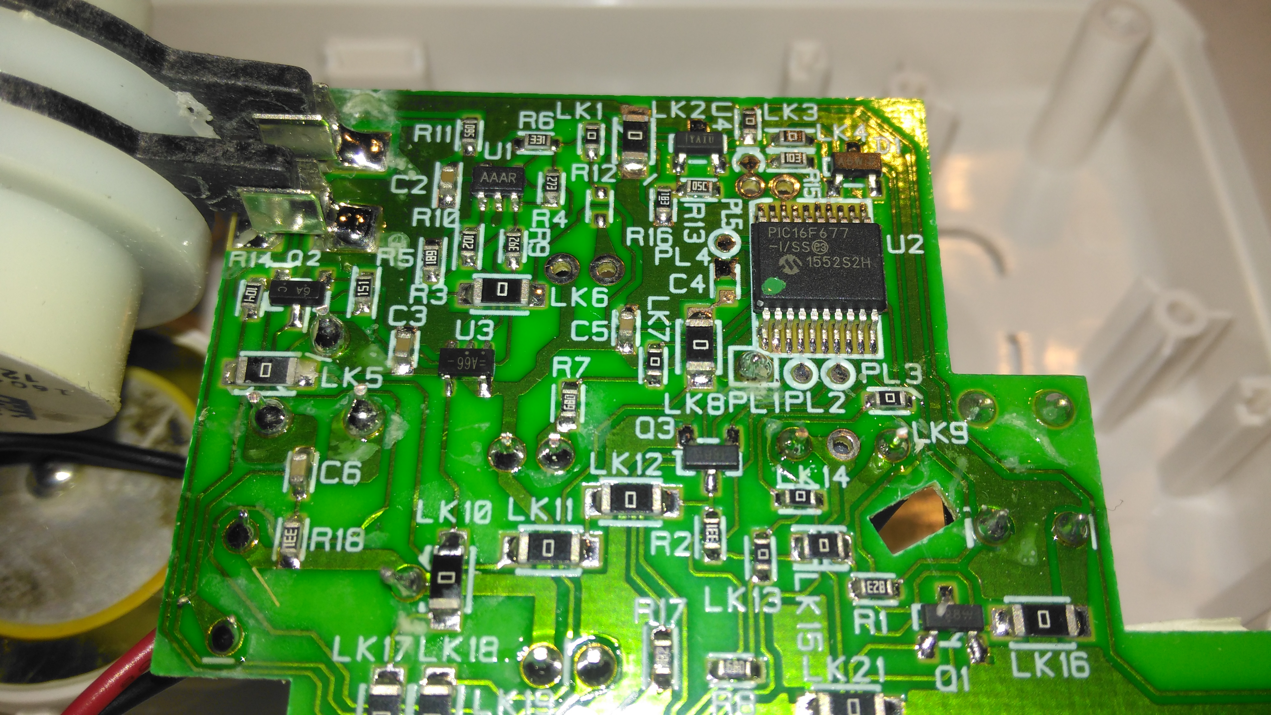
All the magic happens on the bottom of the PCB. The controlling microcontroller is on the top right, with the sensor front end on the top left.
Circuitry Closeup
The microcontroller used here is a Microchip PIC16F677. I’ve not managed to find datasheets for the front end components, but these will just be a low-noise op-amp & it’s ancillaries. There will also be a reference voltage regulator. The terminals on these sensors are made of conductive plastic, probably loaded with carbon.
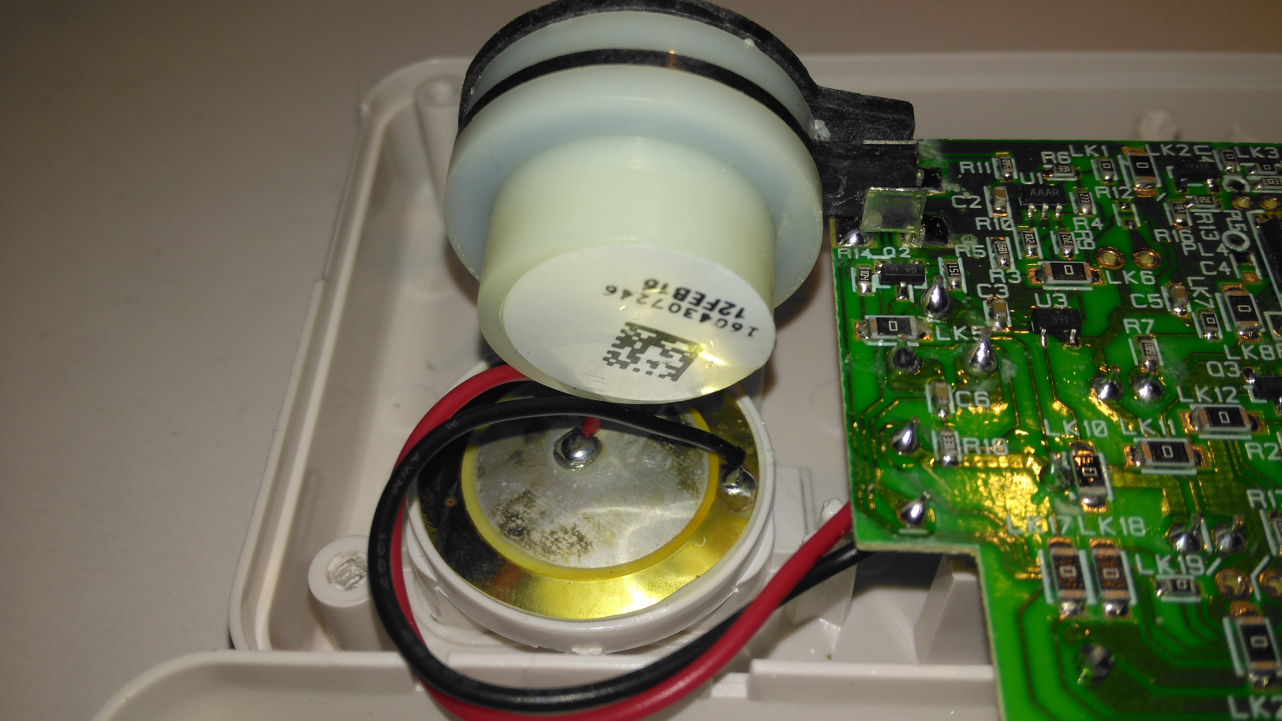
Sensor Cell & Piezo Disc
The expiry date is handily on a label on the back of the sensor, the Piezo sounder is just underneath in it’s sound chamber.
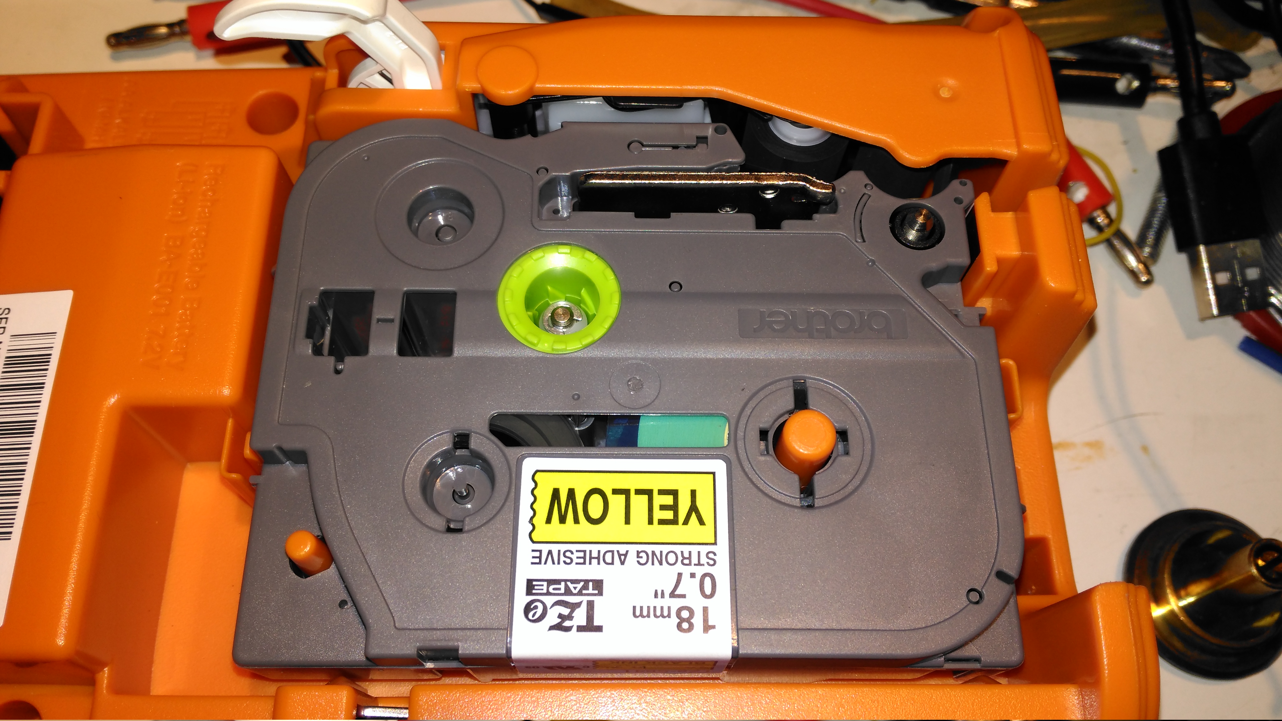
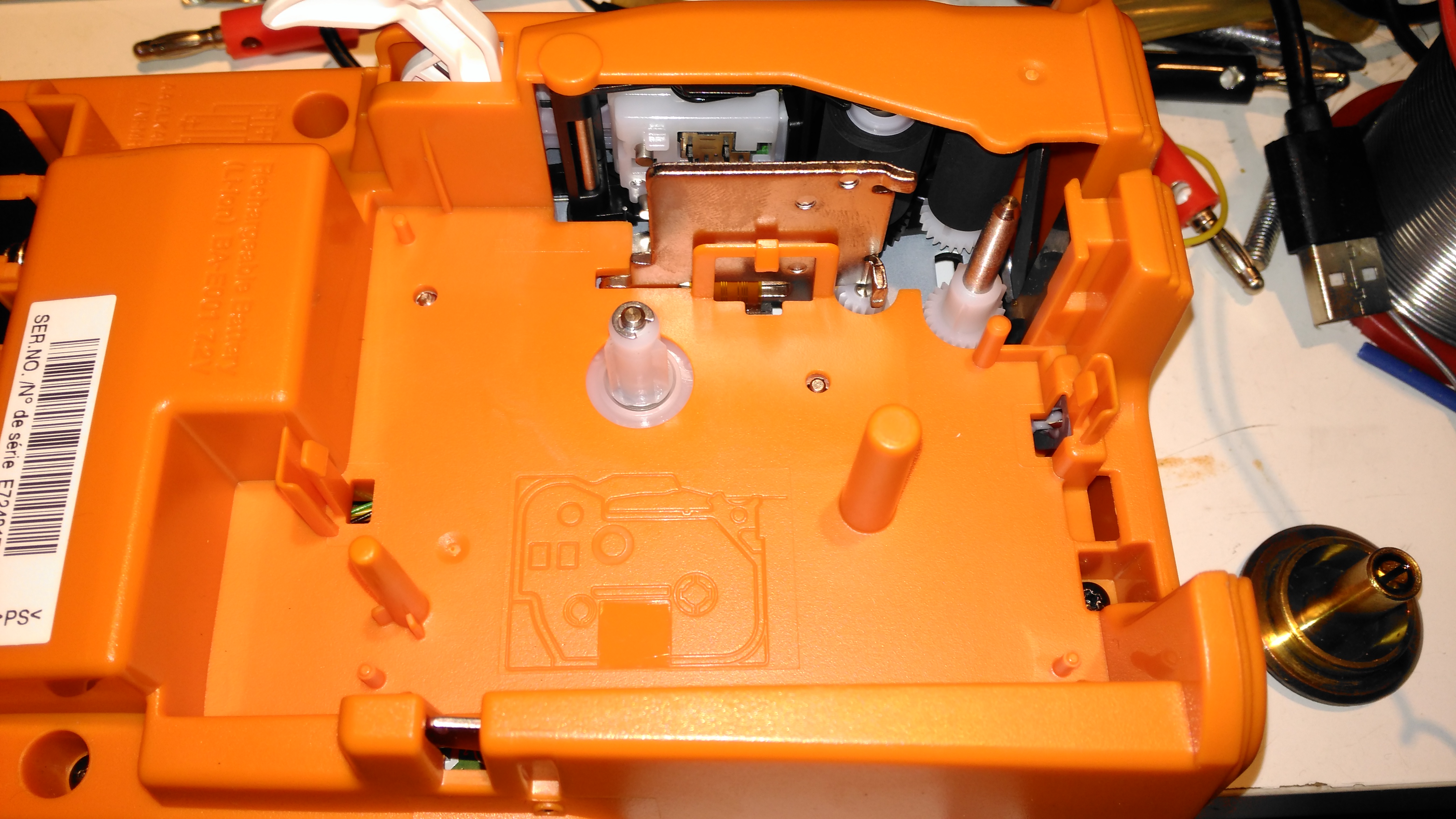
Here a tape is installed in the printer. This unit can handle tape widths up to 18mm. The pinch rollers are operated by the white lever at the top of the image, which engages with the back cover.
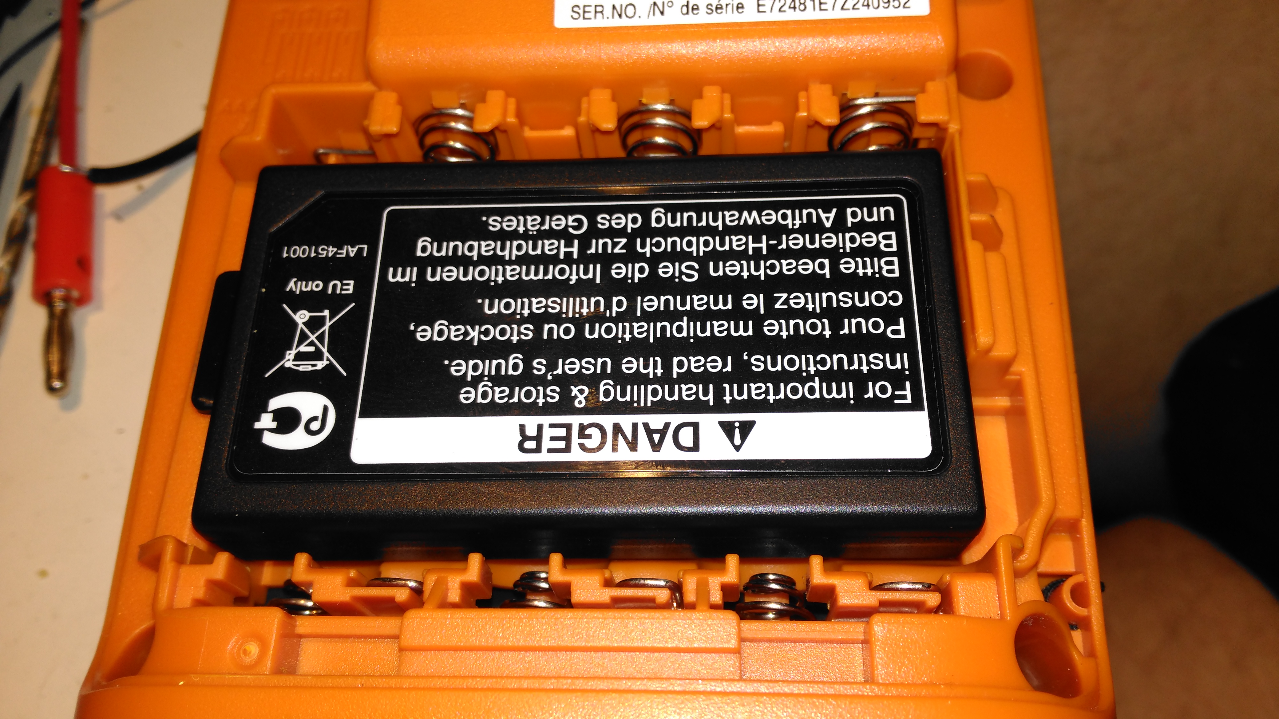
Li-Ion Battery
This printer is supplied with a rechargeable battery pack, but AA cells can be used as well. Some of the AA battery terminals can be seen above the battery.
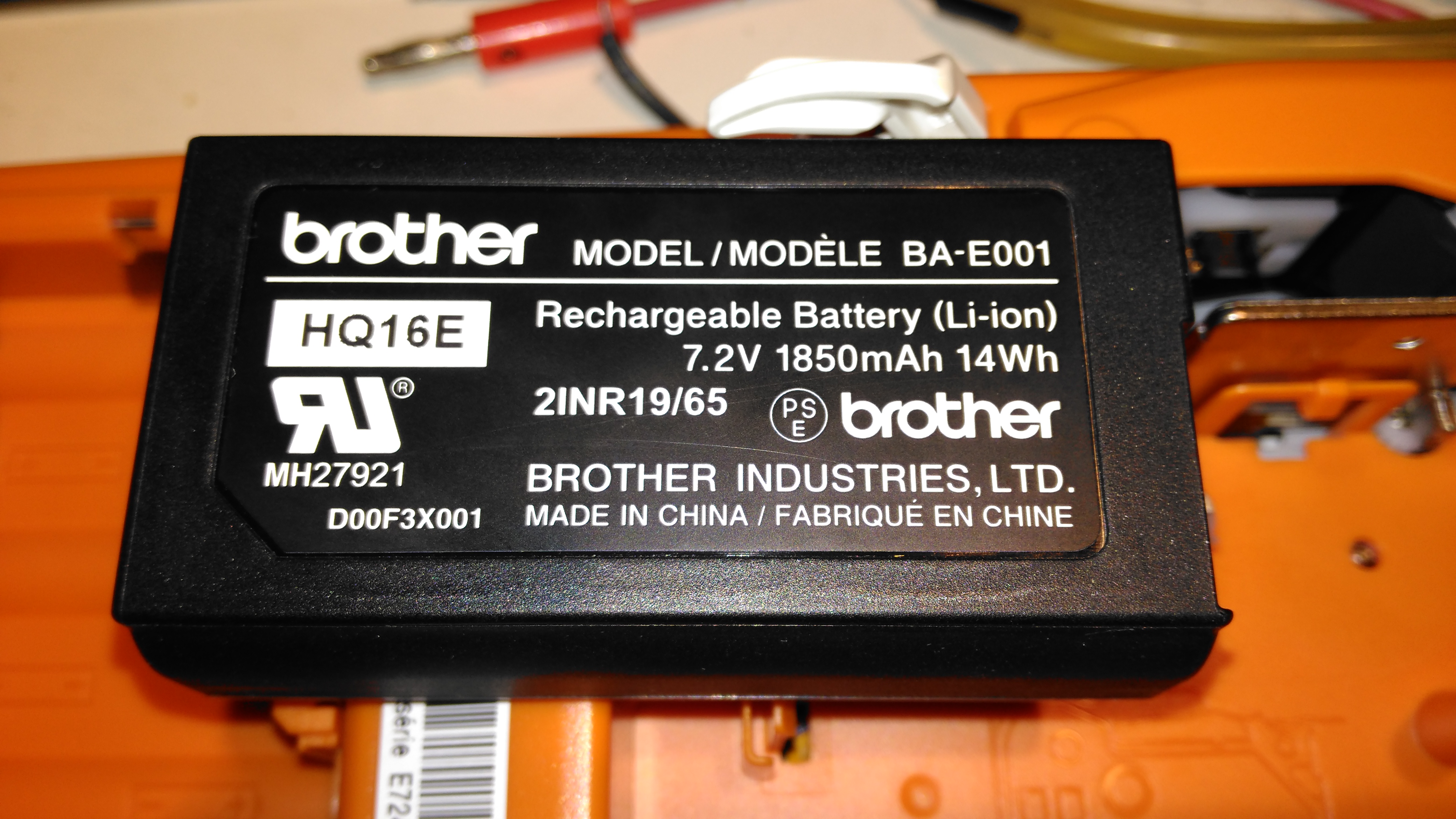
Battery Specs
Pretty standard fare for a 2-cell lithium pack. The charging circuitry doesn’t appear to charge it to full voltage though, most likely to get the most life from the pack.
Cartridge Slot
With the cartridge removed, the printer components can be seen. As these cartridges have in effect two rolls, one fro the ribbon & one for the actual label, there are two drive points.
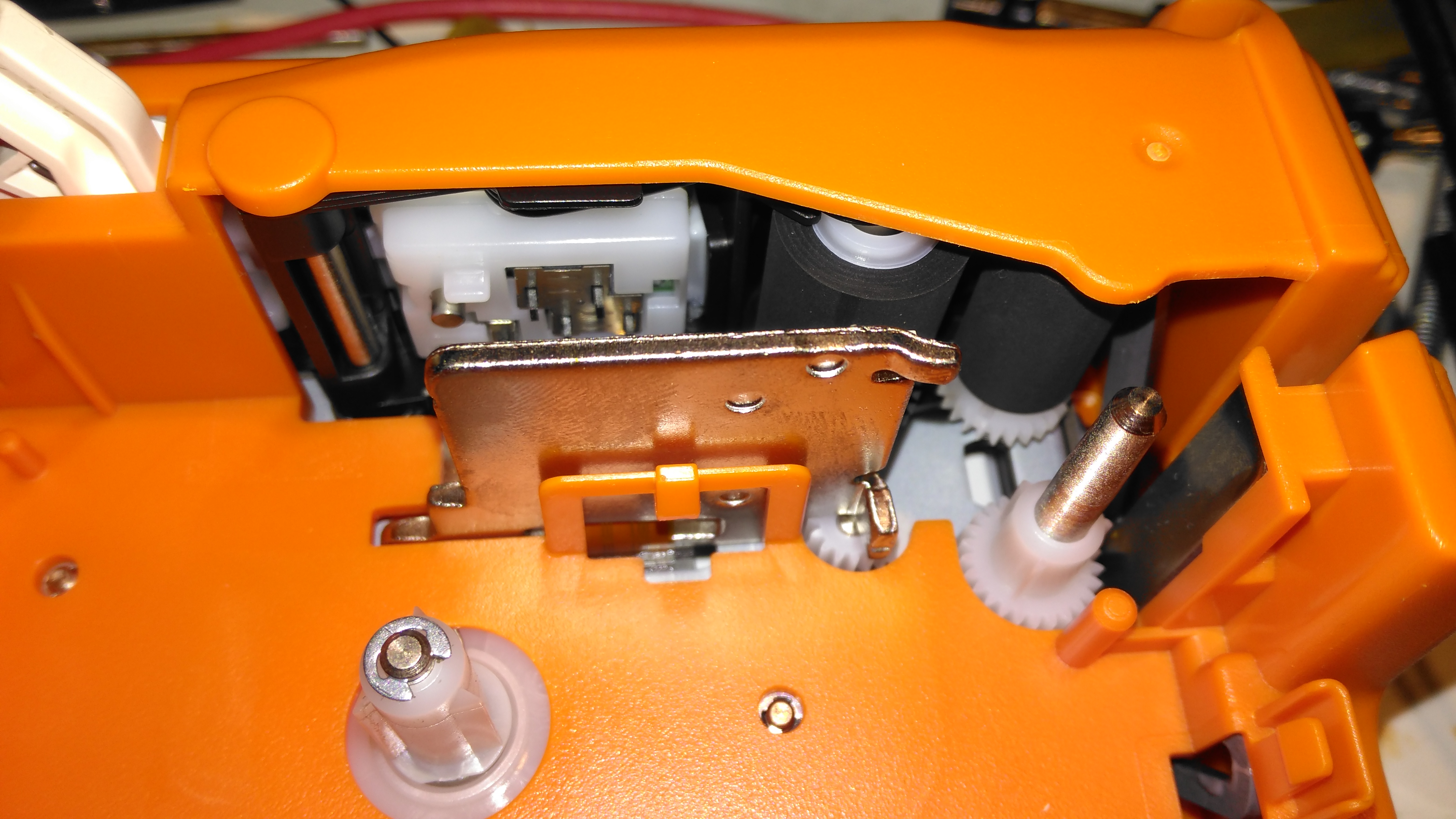
Pinch Rollers & Print Head
The thermal print head is hidden on the other side of the steel heatsink, while the pinch rollers are on the top right. The plastic piece above the print head heatsink has a matrix of switches that engage with holes in the top of the label cartridge, this is how the machine knows what size of ribbon is fitted.
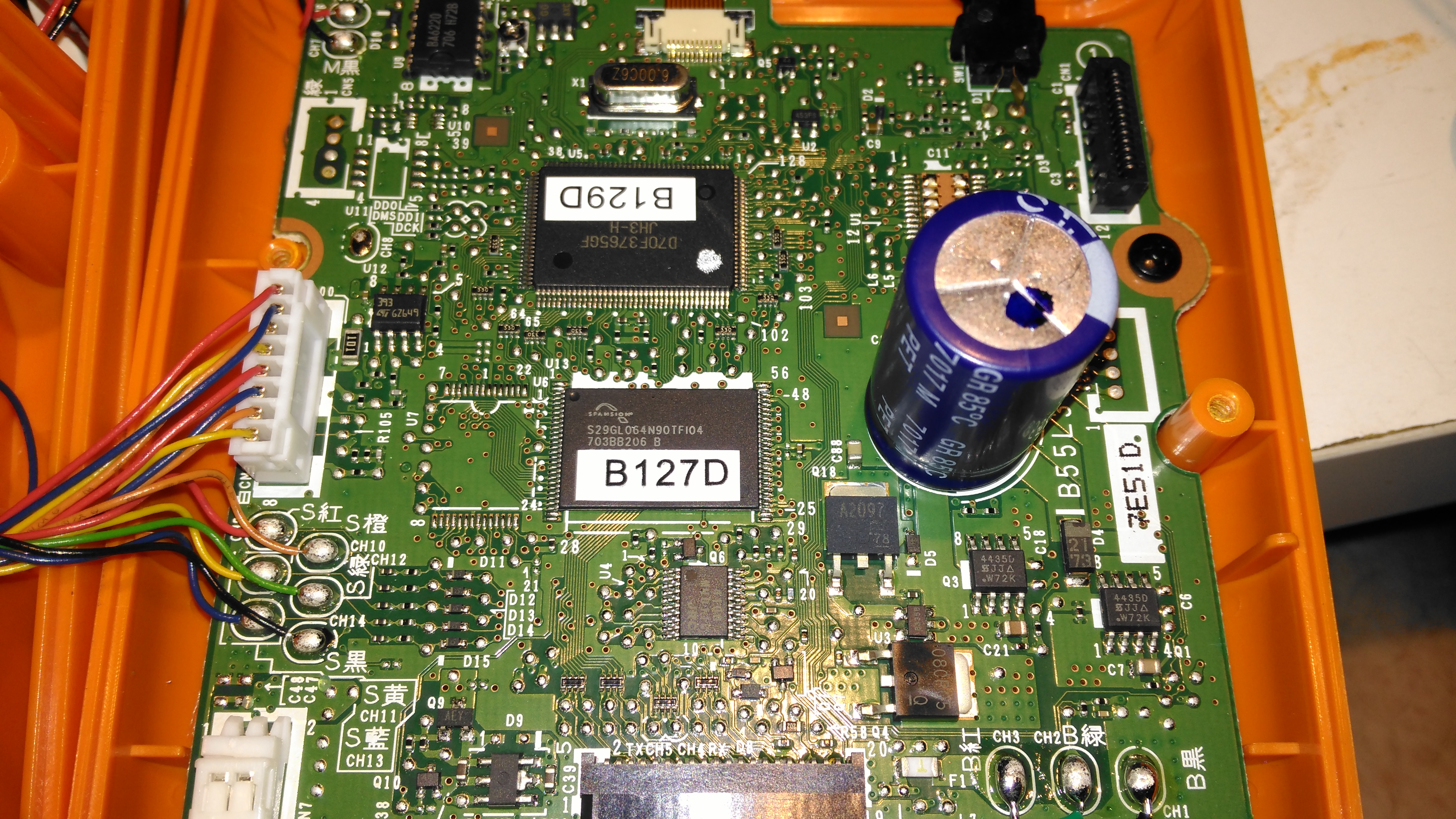
Mainboard
Most of the internal space is taken up by the main board, with the microprocessor & it’s program flash ROM top & centre.
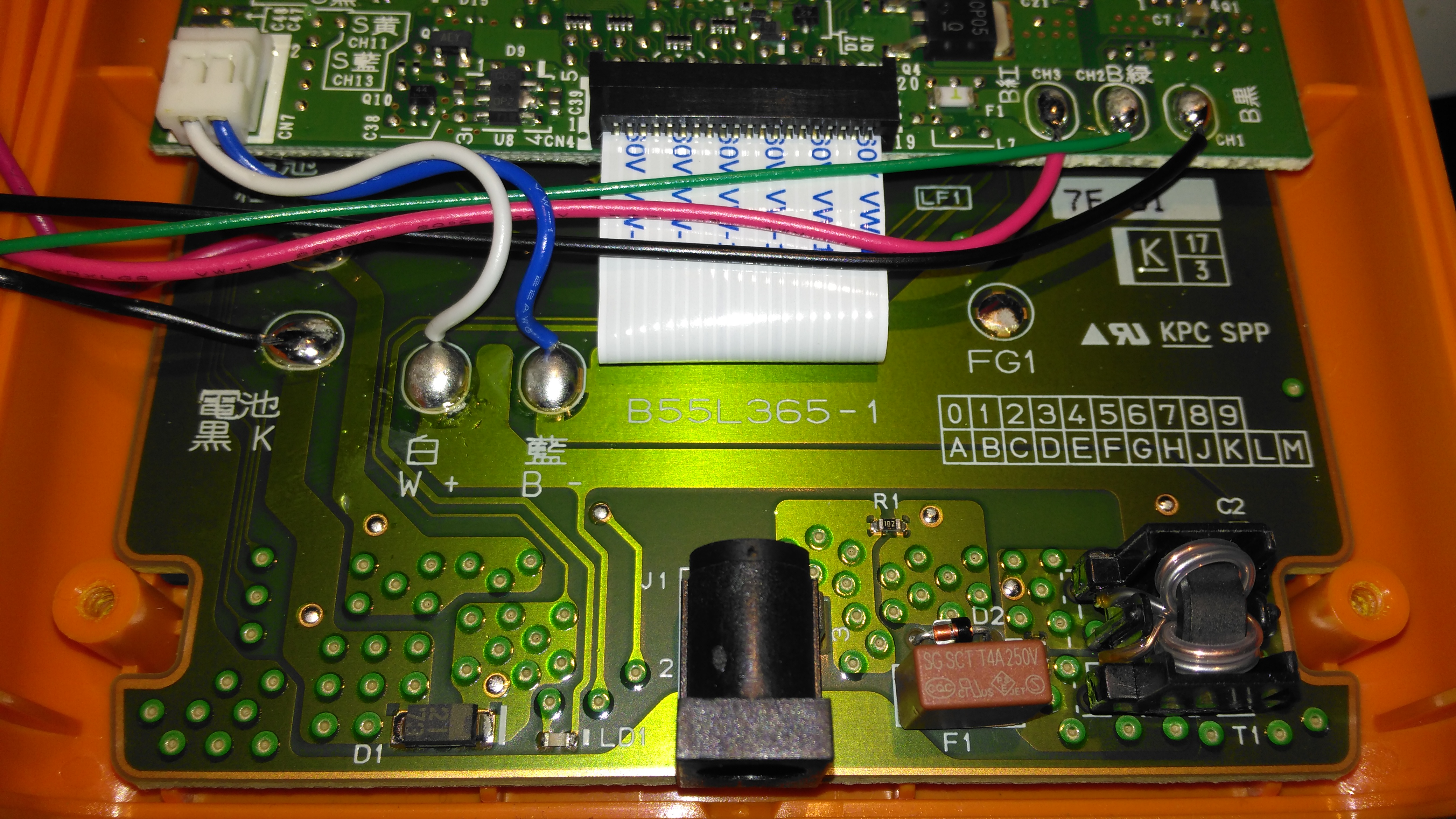
Charger Input
The charger input is located on the keyboard PCB just under the mainboard, which is centre negative, as opposed to 99% of other devices using centre positive, the bastards.
LCD Module
The dot-matrix LCD is attached to the mainboard with a short flex cable, and from the few connections, this is probably SPI or I²C.
Print Mech Drive
The printer itself is driven by a simple DC motor, speed is regulated by a pair of photo-interrupters forming an encoder on the second gear in the train.
Battery Holder Connections
The back case has the battery connections for both the lithium pack & the AA cells, the lithium pack has a 3rd connection, probably for temperature sensing.
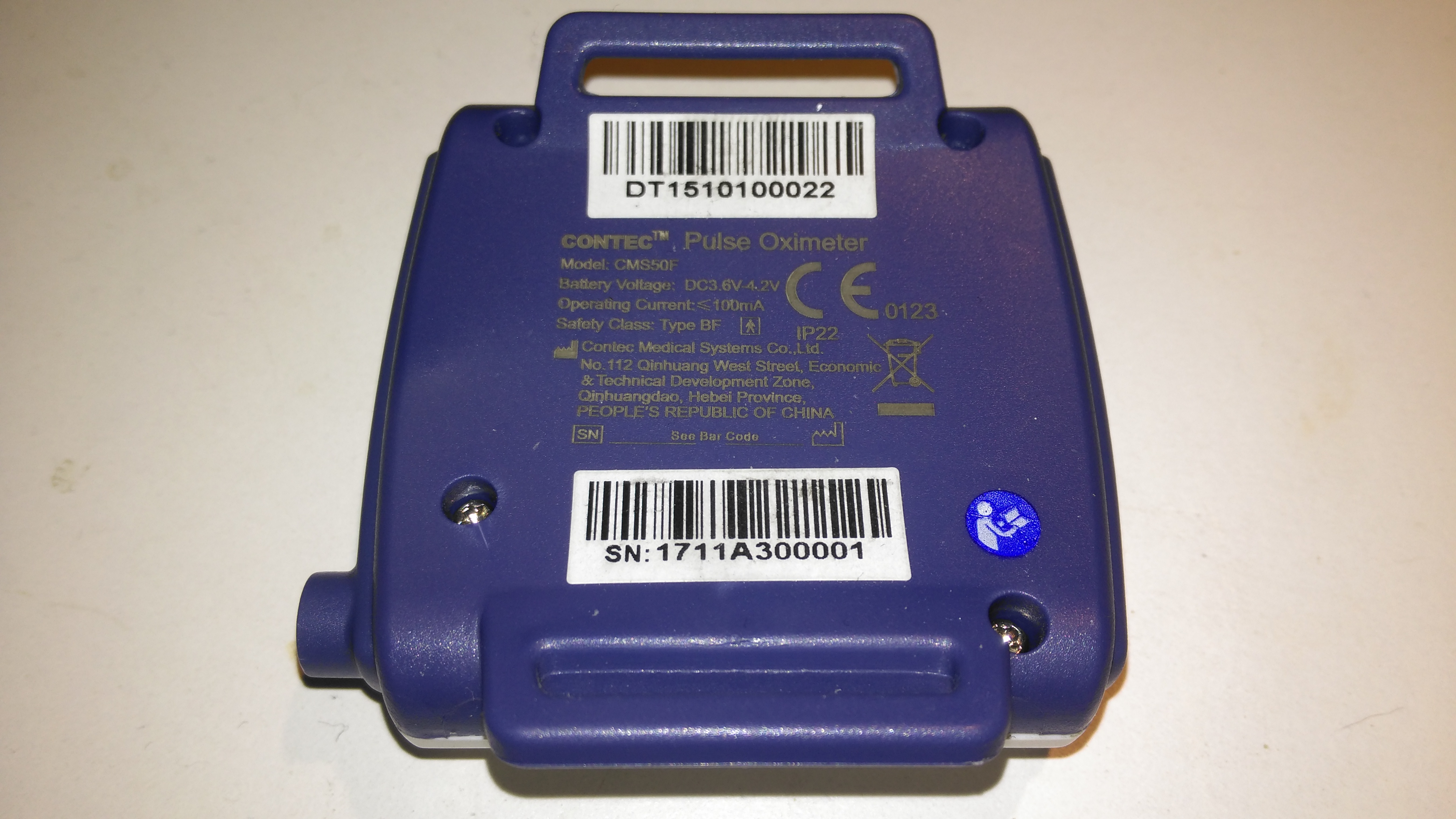
The rear has the specifications, laser-marked into the plastic. The serial numbers are just sticky labels though, and will come off easily with use.
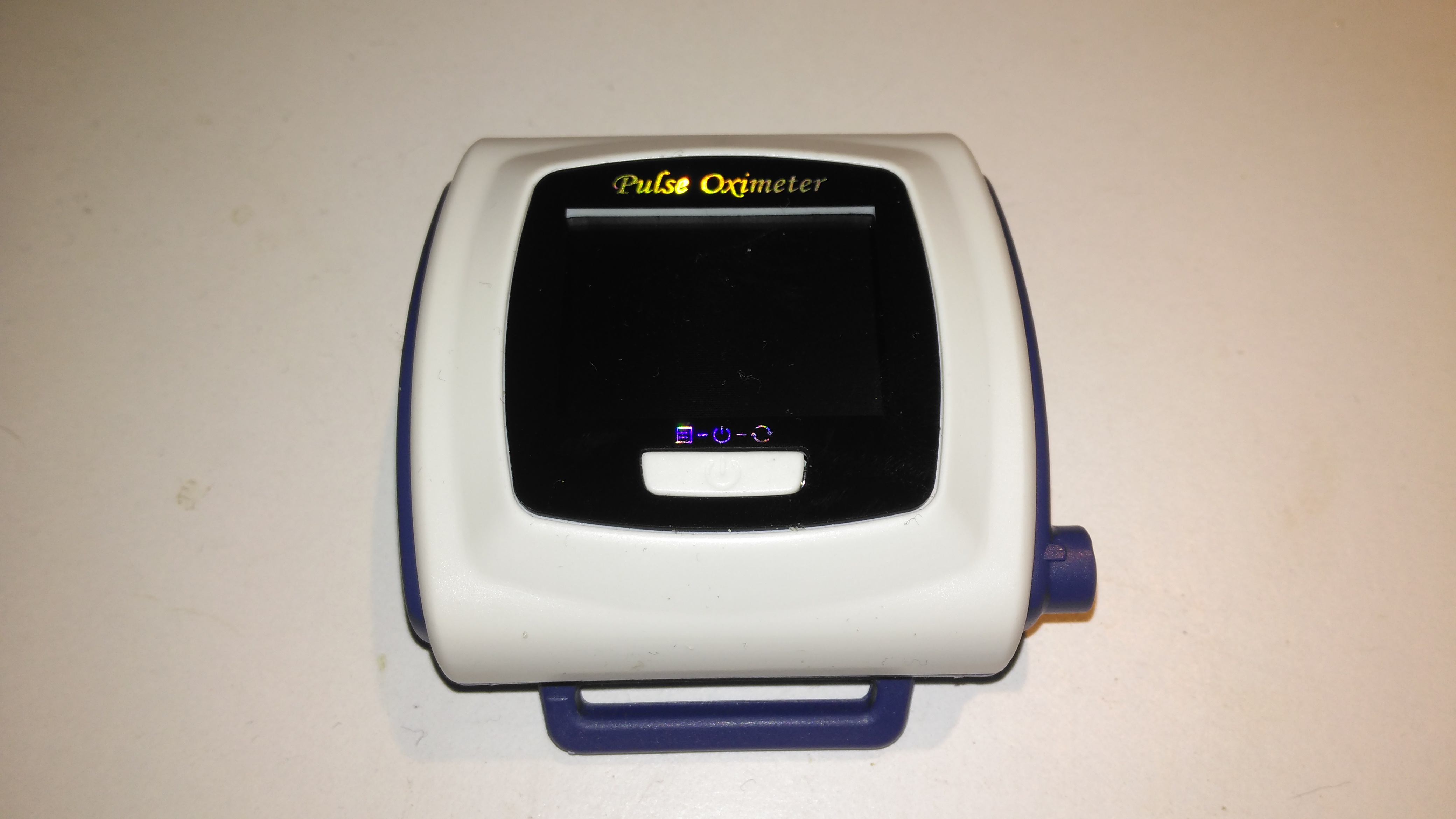
Contec CMS-50F
This is the Contec CMS-50F wrist-mounted pulse oximeter unit, which has the capability to record data continuously to onboard memory, to be read out at a later time via a USB-Serial link. There is software supplied with the unit for this purpose, although it suffers from the usual Chinese quality problems. The hardware of this unit is rather well made, the firmware has some niggles but is otherwise fully functional, however the PC software looks completely rushed, is of low quality & just has enough functionality to kind-of pass as usable.
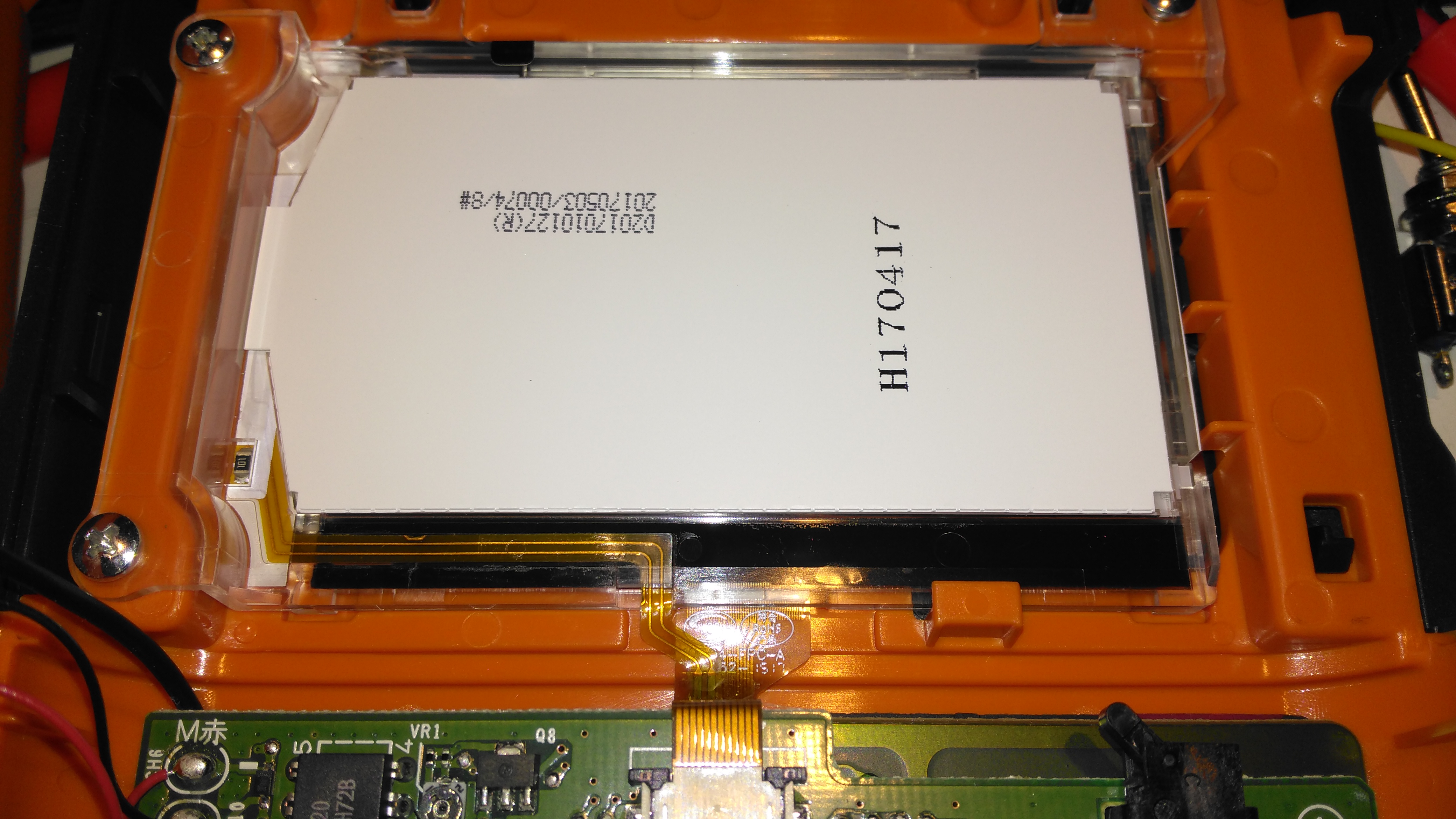
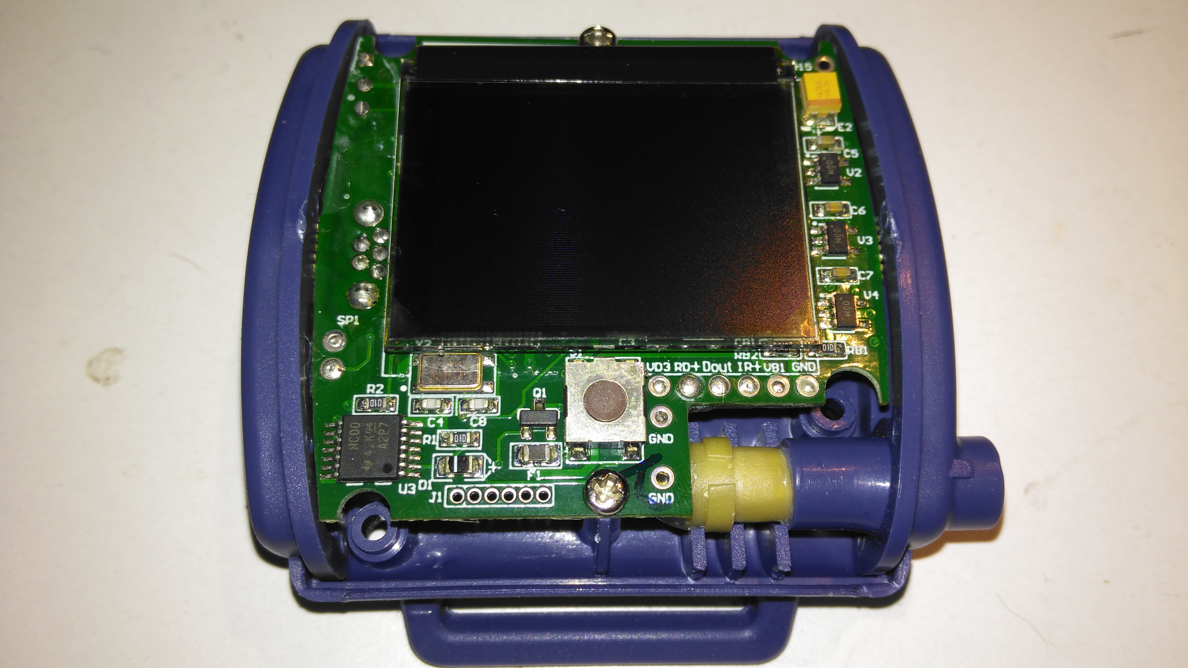
Top Cover Removed
A total of 4 screws hold the casing together, once these are removed the top comes off. The large colour OLED display covers nearly all of the board here. The single button below is the user interface. The connection to the probe is made via the Lemo-style connector on the lower right.
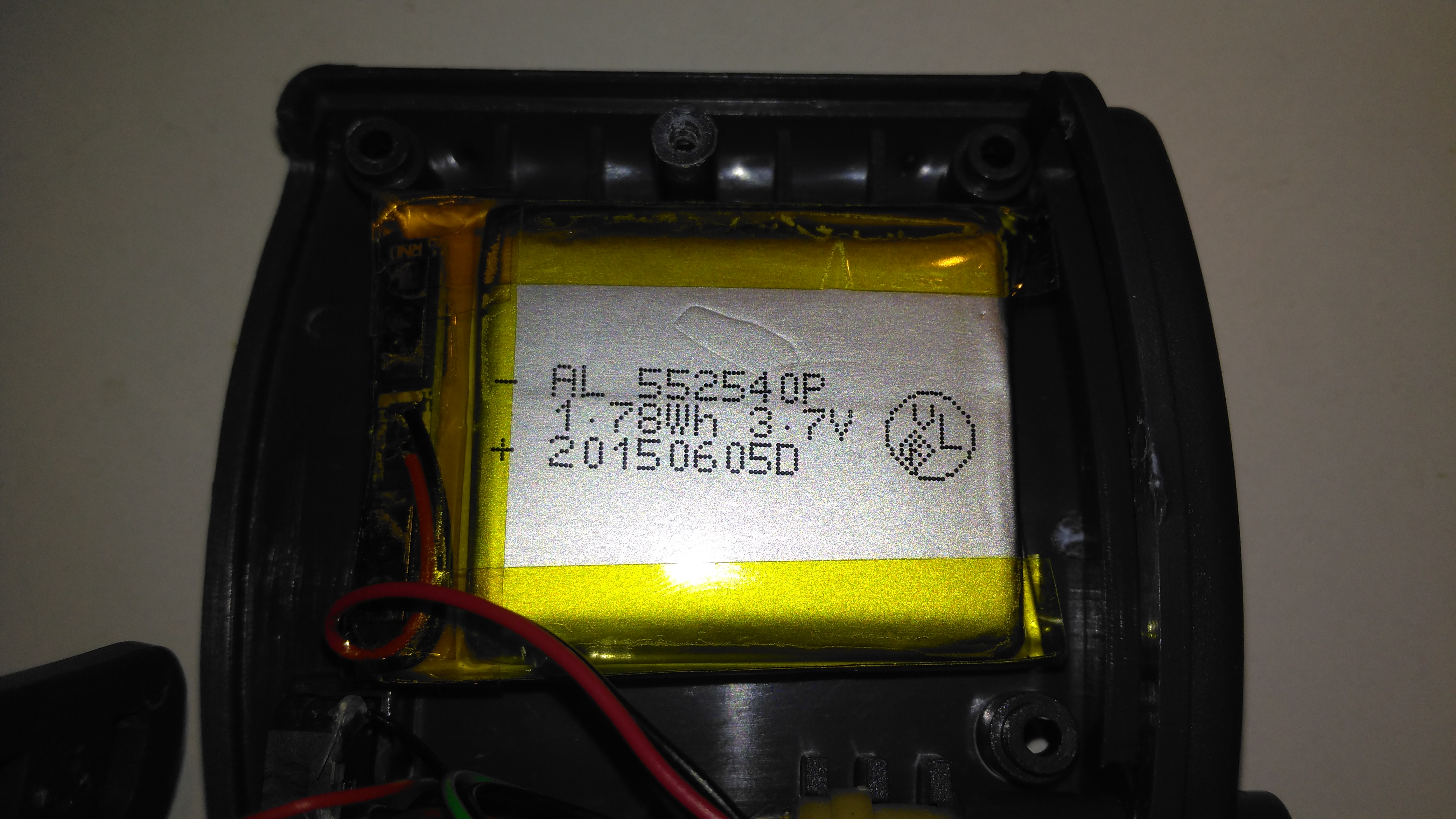
Lithium Cell
Power is provided by a relatively large lithium-ion cell, rated at 1.78Wh.
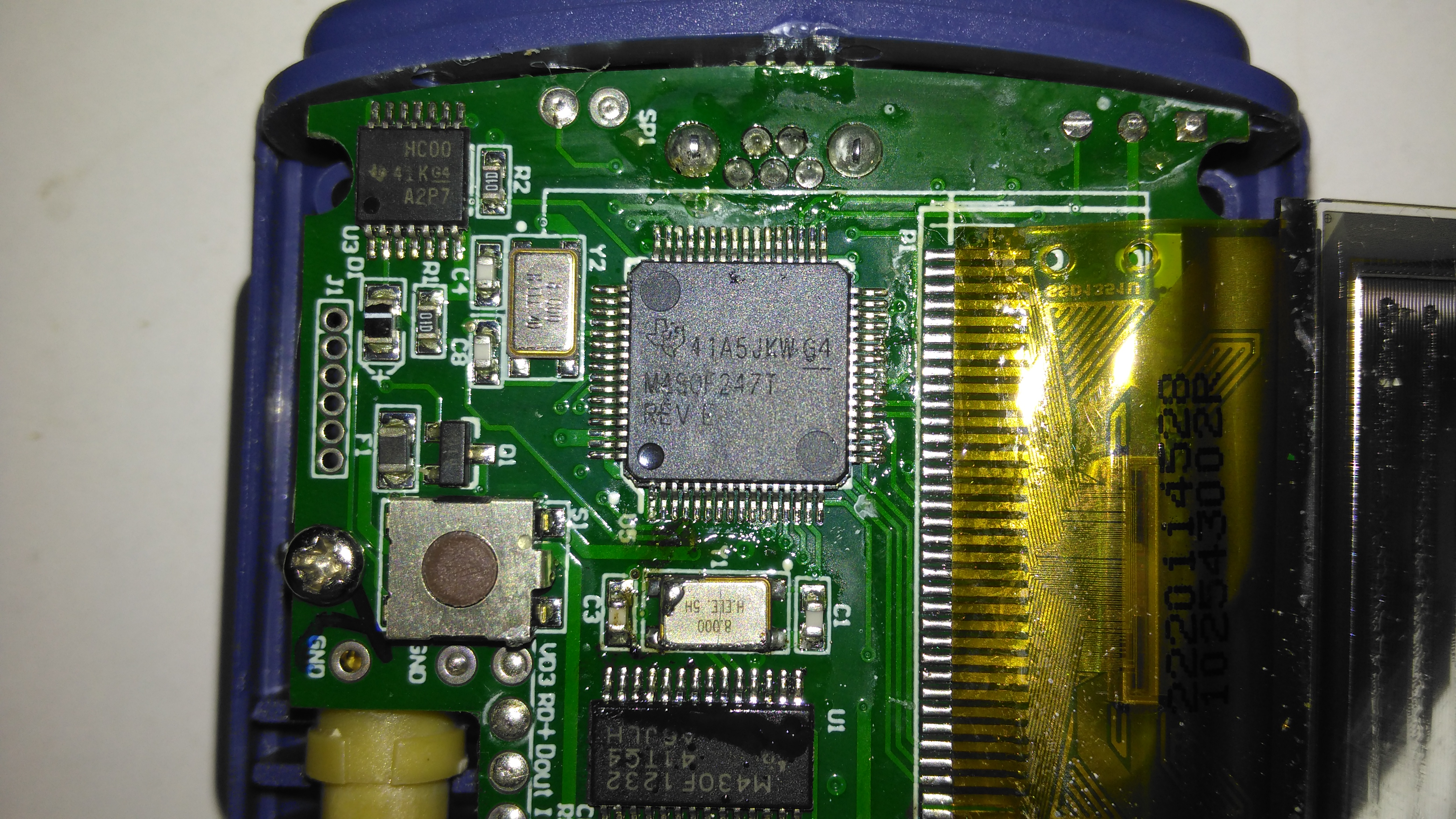
Main Processor
All the heavy lifting work of the LCD, serial comms, etc are handled by this large Texas Instruments microcontroller, a MSP430F247. The clock crystal is just to the left, with the programming pins. I’m not sure of the purpose of the small IC in the top left corner, I couldn’t find any reference to the markings.
Aux Processor
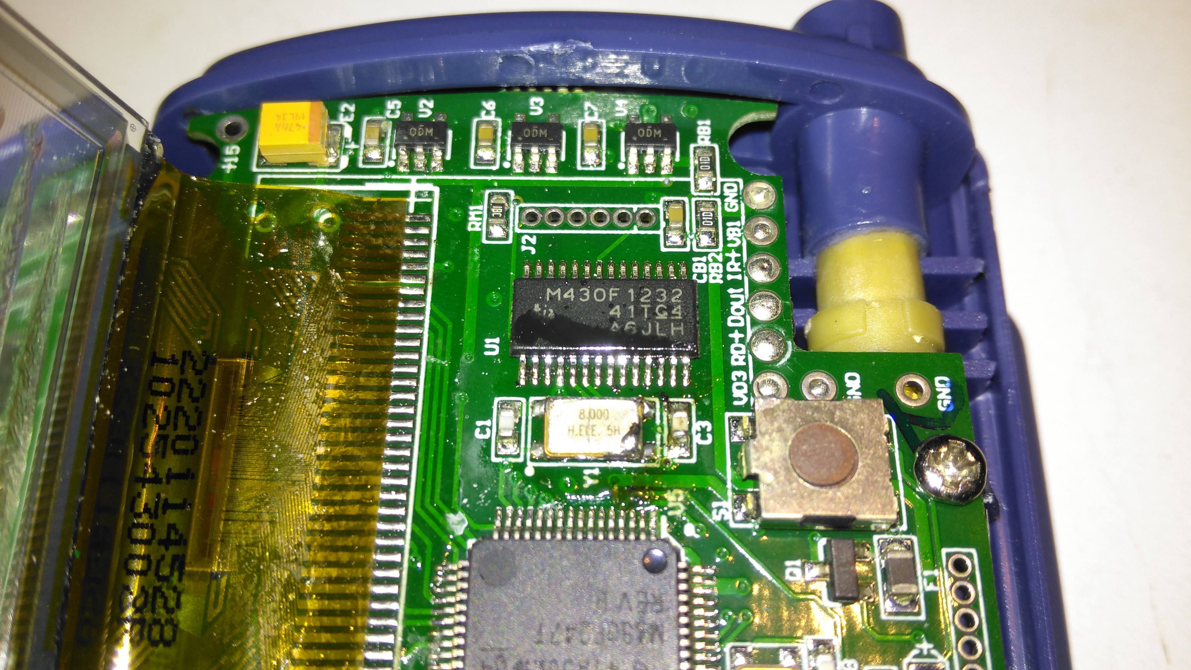
The actual pulse oximetry sensor readings seem to be dealth with by a secondary microcontroller, a Texas Instruments M430F1232 Mixed-Signal micro. This has it’s own clock crystal just underneath. The connections to the probe socket are to the right of this µC, while the programming bus is broken out to vias just above. The final devices on this side of the board are 3 linear regulators, supplying the rails to run all the logic in this device.
Main PCB Rear
The rear of the PCB has the SiLabs CL2102 USB-Serial interface IC, the large Winbond 25X40CLNIG 512KByte SPI flash for recording oximetry data, and some of the power support components. The RTC crystal is also located here at the top of the board. Up in the top left corner is a Texas Instruments TPS61041 Boost converter, with it’s associated components. This is probably supplying the main voltage for the OLED display module.
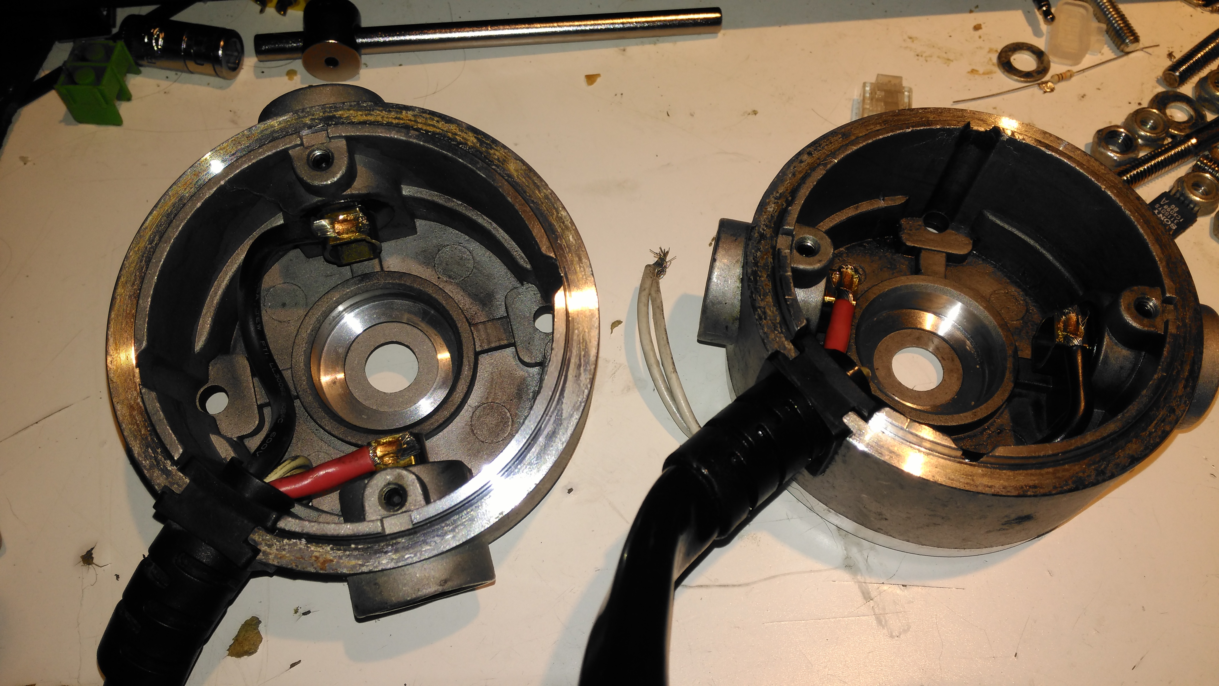
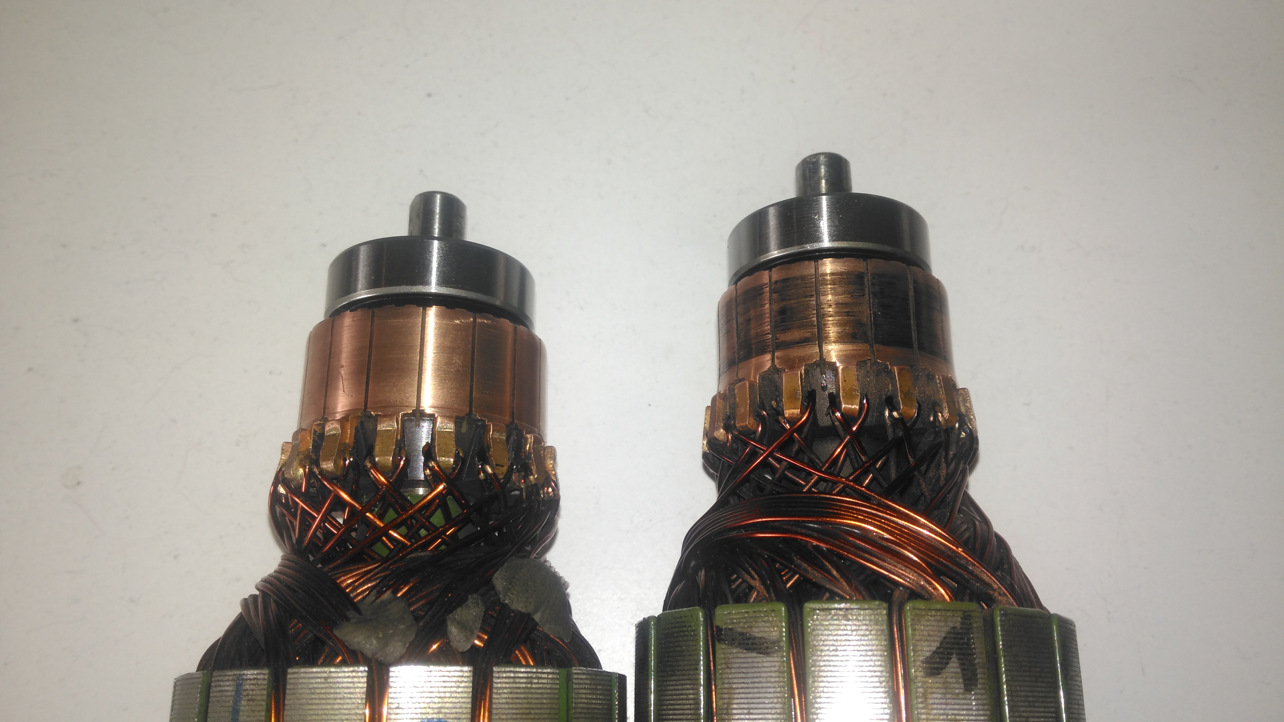
The housing of the contaminated motor was left to soak in diesel for a few hours to loosen the grok, this has come very clean. I couldn’t have used a stronger solvent here – the magnets are glued in place in the steel housing, I certainly didn’t want them coming loose!
Brushboxes
Next into the diesel bath are the motor end bells with the brushgear. Attack with a stiff brush cleaned these up very well, some cotton buds served to clean out the brass brush holders.
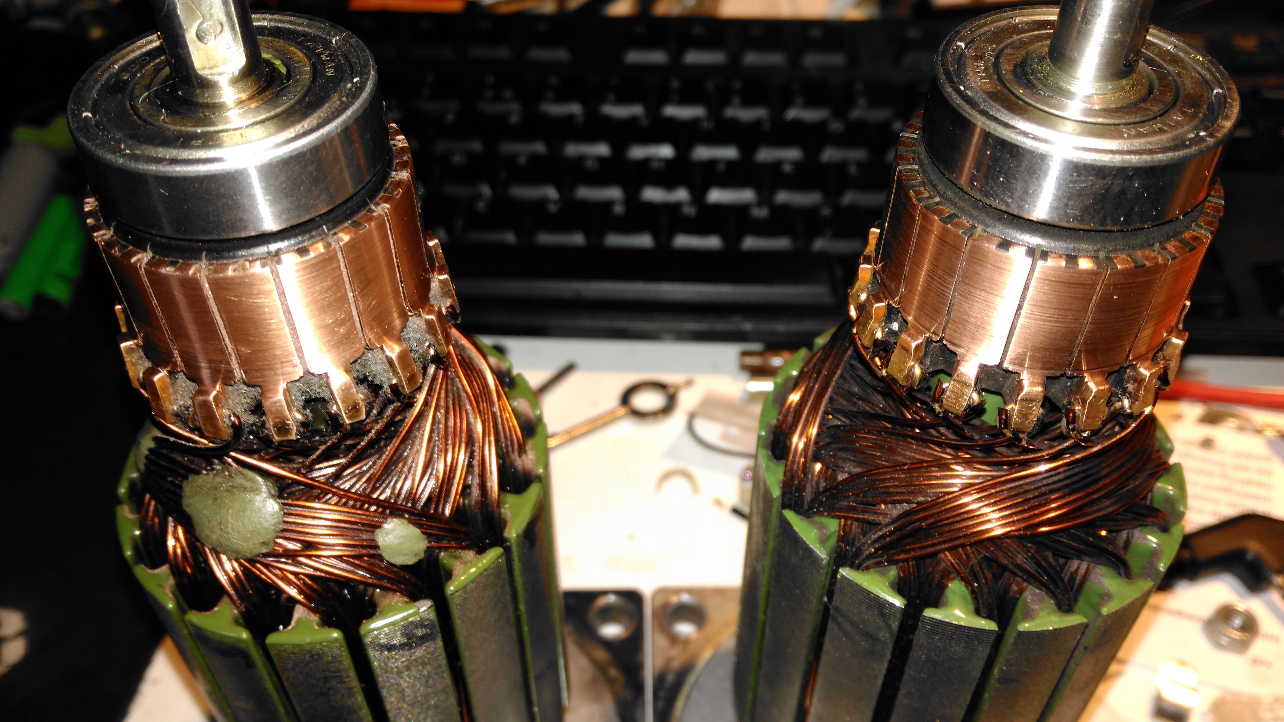
Armatures After Skimming
Here are both armatures, having had their commutators resurfaced. I’ve completely removed all traces of the wear caused by the contamination, luckly the commutator bars are very heavy on these motors so can take quite a bit of wear before there’s not enough left to skim. I’ve not yet pulled off the old bearings, but they are all going to be replaced with new SKF bearings, as they’ve been contaminated with grok over the years of use. I’m also going to uprate the front motor bearings to rubber sealed instead of metal shielded, to help keep lubricant out of the motors if the gearbox seals ever fail again.
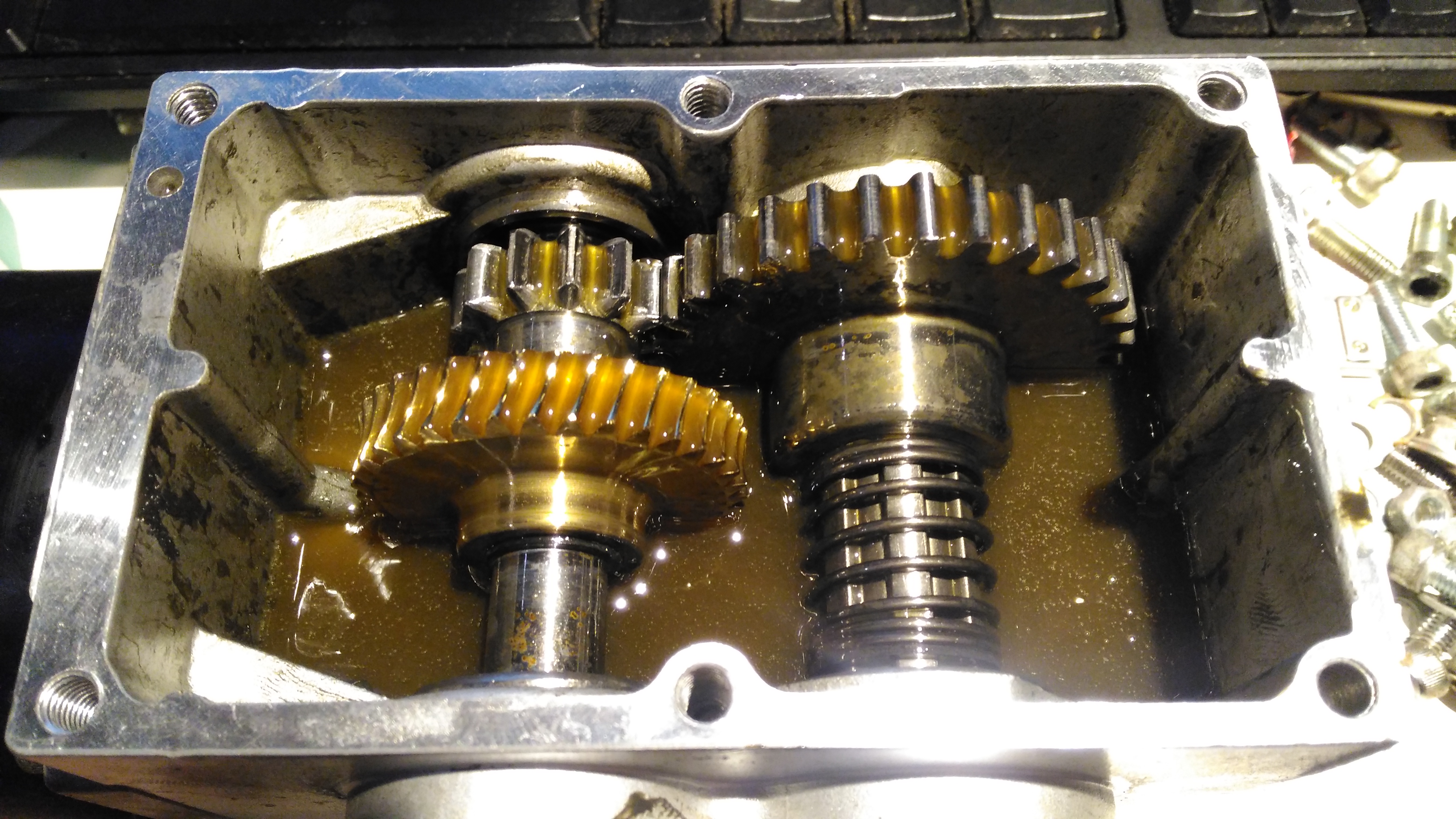
Gearbox
The gearboxes have been cleaned out with some elbow grease, assisted by a long soak in petrol, I’ve refilled them here with engine oil as temporary lube & to flush out the last remains of the old grease & solvent. The worm wheel in these boxes is bronze – so a GL4 gear oil will be required. (Some Extreme Pressure additive packs contain sulphur, and will readily attack copper alloys, such as brass & bronze).
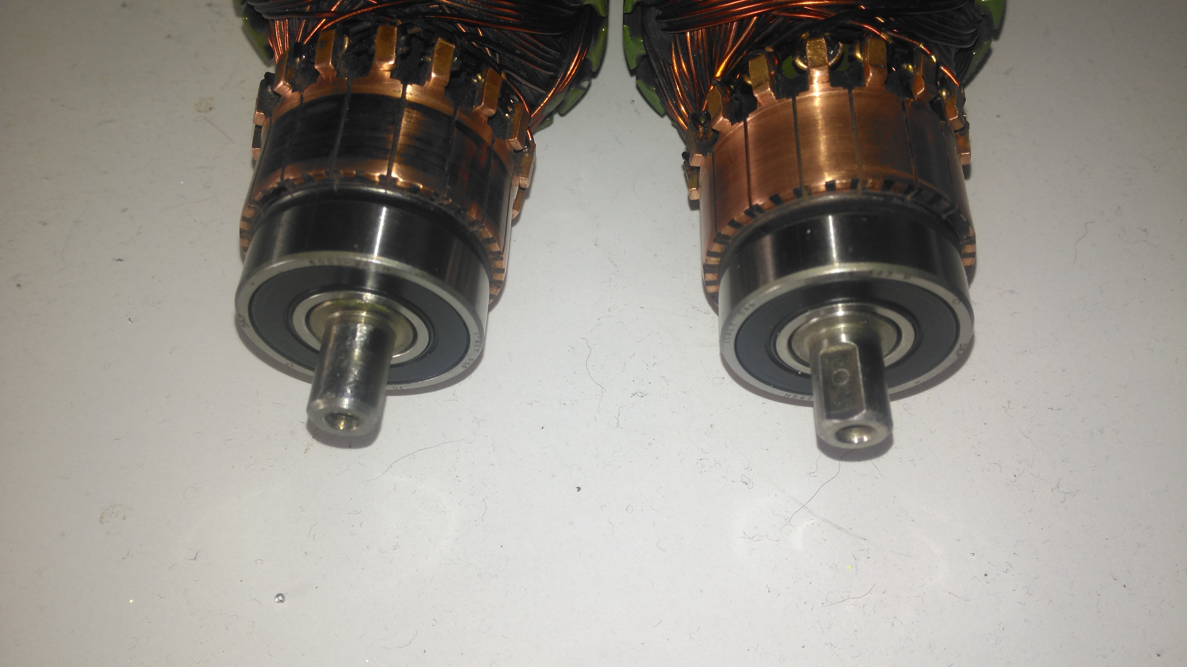
Commutator End Bearings
Here’s the armatures, after the new SKF sealed bearings have been fitted to the commutator end, above, and the drive end, below. These will cause some extra drag on the armatures, and slightly higher power consumption as a result, but keeping the crap out of the motors is slightly more important.
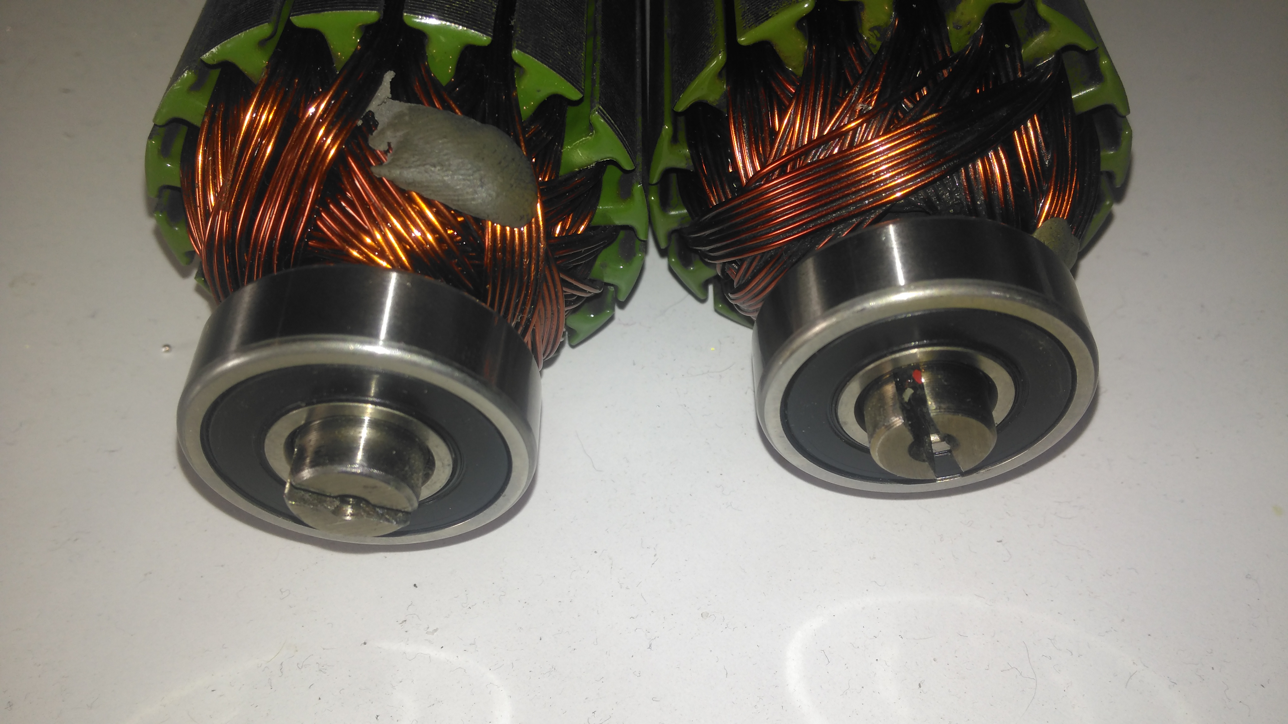
Drive End BearingsFresh Commutator Skim
The commutators have been lightly skimmed with abrasive cloth, and finished with 1500 grit emery. The armature on the right has been run for a short time to see how the new brushes are bedding in.
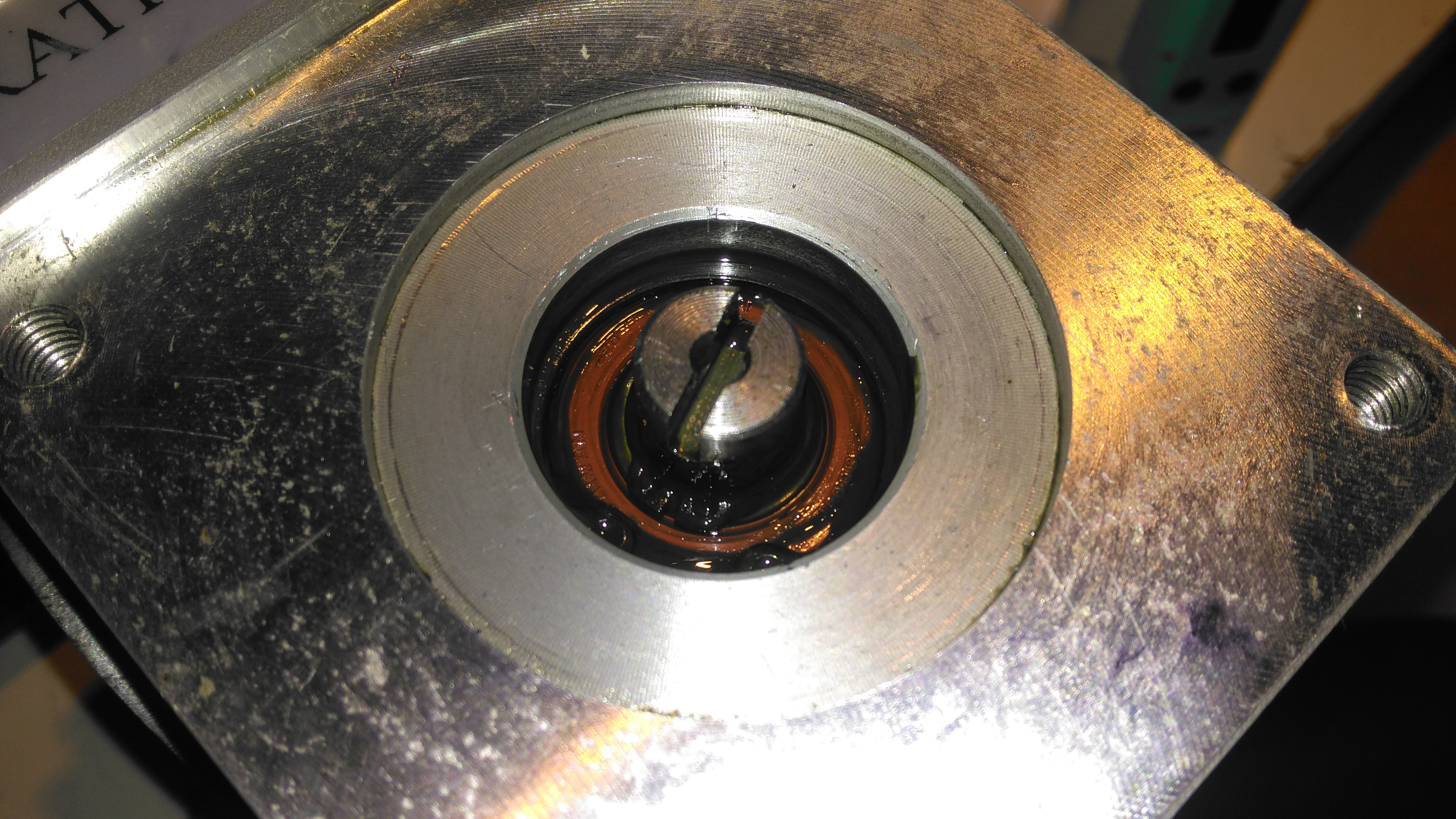
Old Seal Removed
Finally, the old oil seals are pulled from the gearboxes. The worm gear bearing on the inside is actually a sealed version, with the external oil seal providing some extra sealing. I haven’t changed the gearbox bearings, as they seem to be in good order, this might get done at some point in the future.
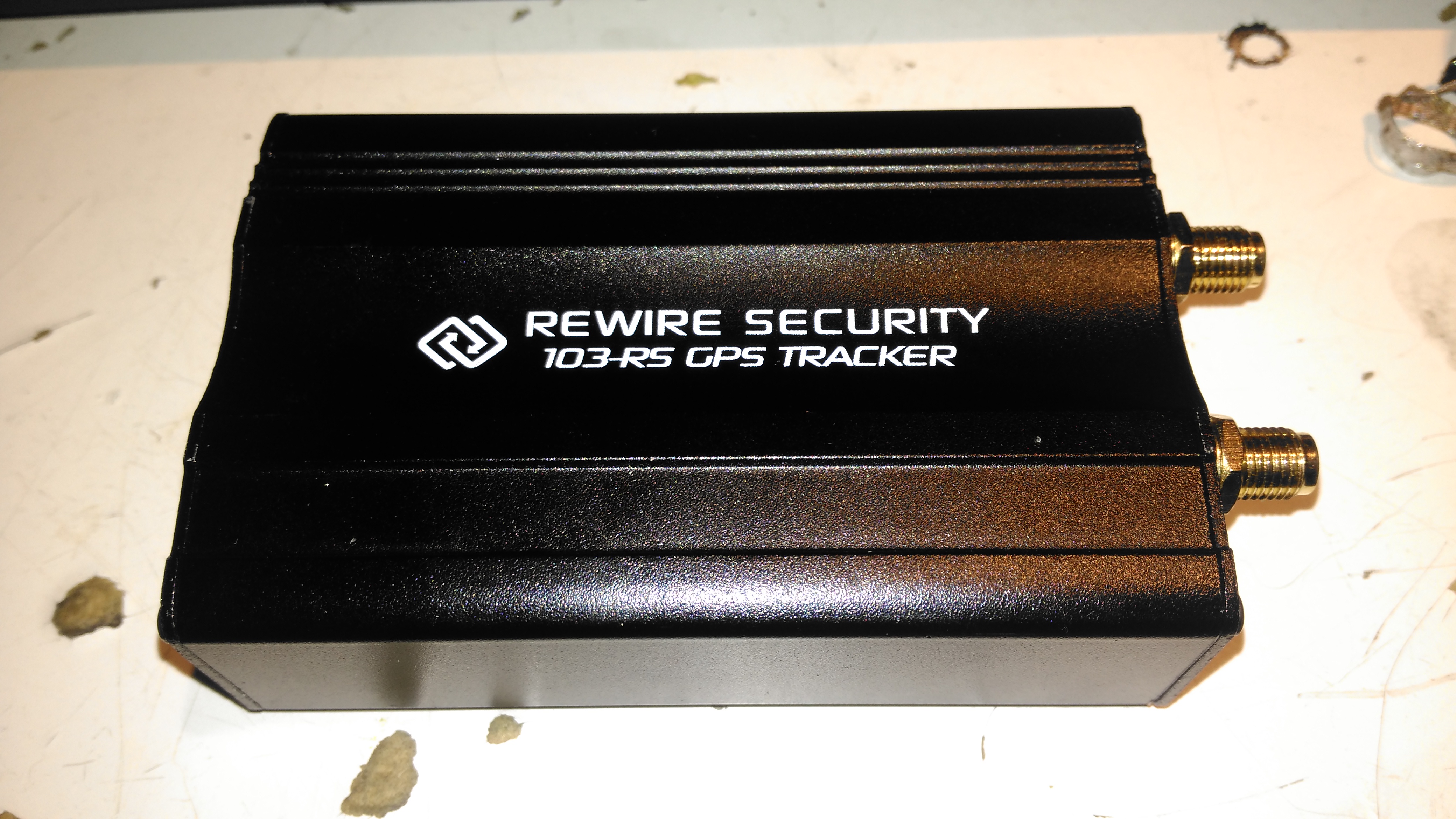
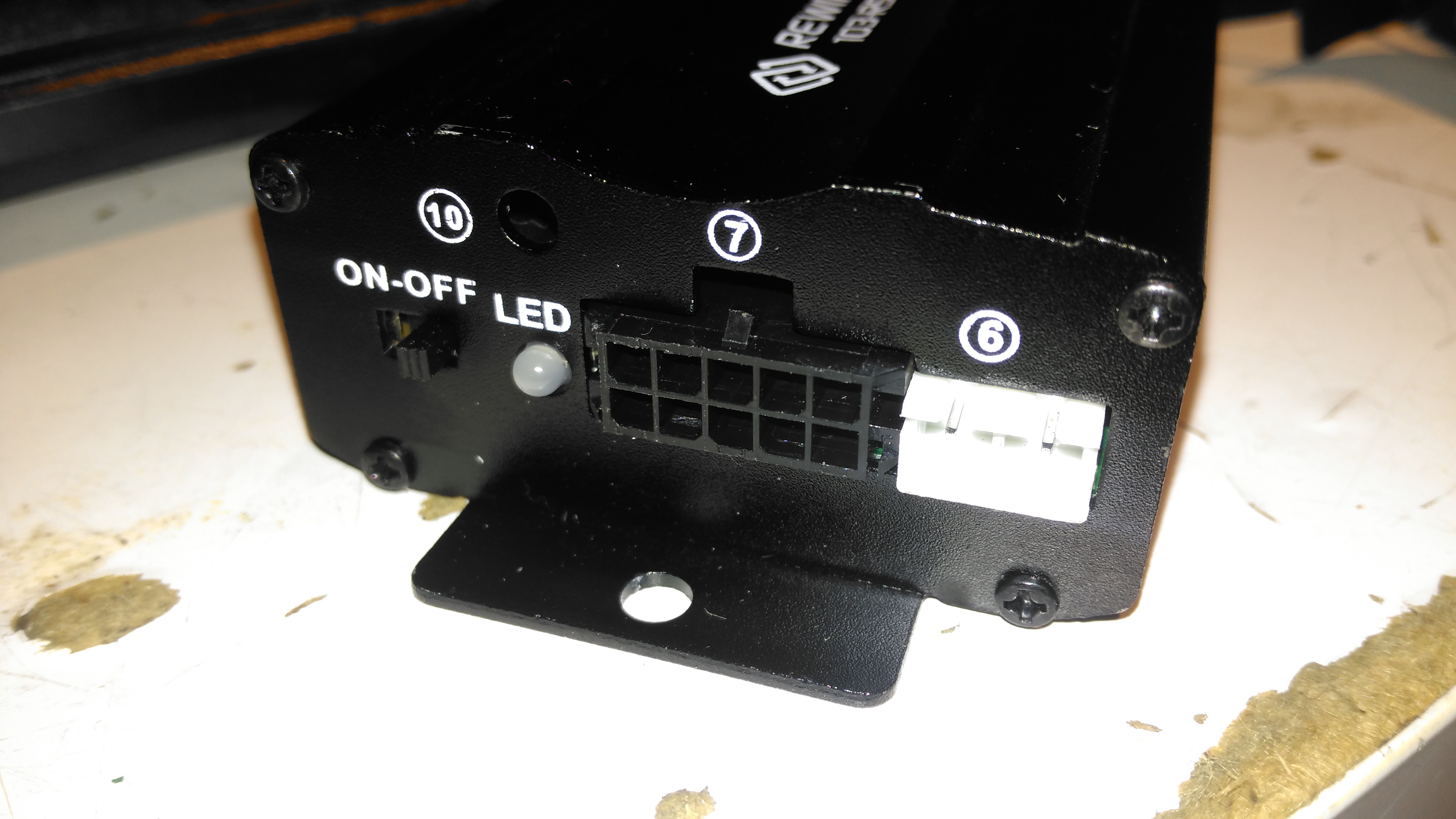
I thought it was time to add a bit of security to the gear I take camping, so this GPS tracker unit was sourced from eBay. This is a Rewire Security 103RS, a slightly customised version of the common Chinese TK103 GPS tracker.
Input Connections
The small module has all it’s power connections on one end of the unit, on a Molex multi-way block. The white connector is for a piezo-shock sensor – this interfaces with the alarm functionality of the unit. There’s an indicator LED for both the GPS & GSM status, and a switch for the backup battery.
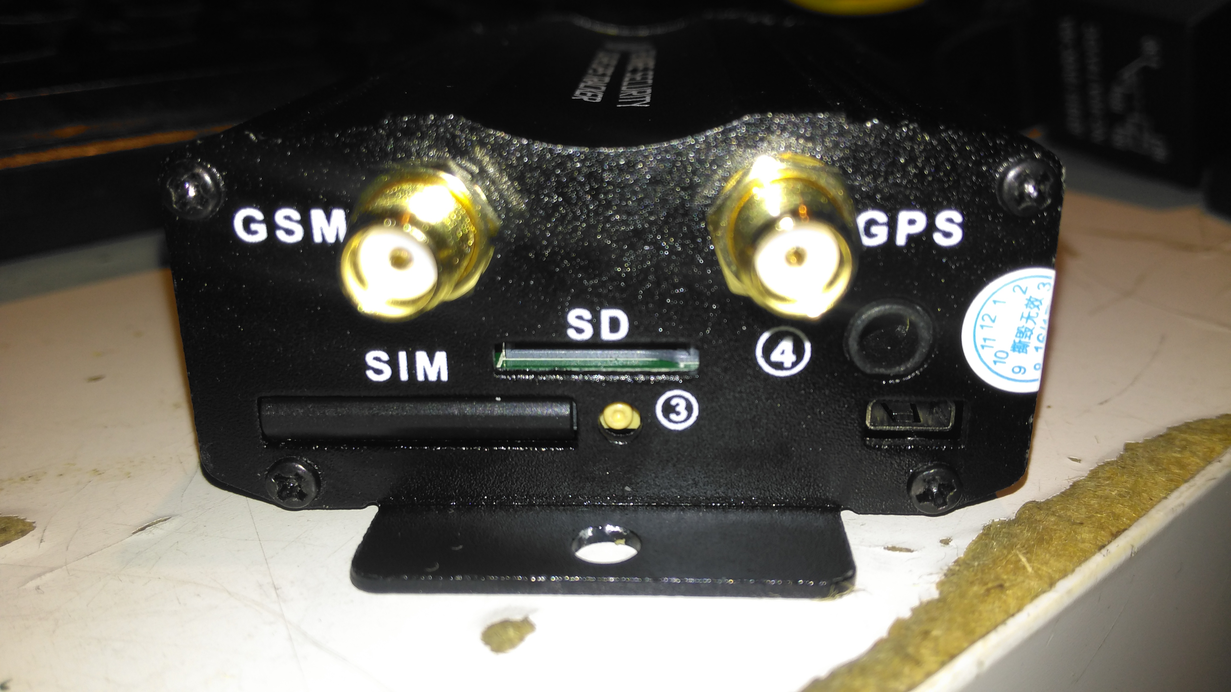
Antenna Connections
The other end has the antenna connections, microphone connection for the monitor function, along with the SIM & SD card slots.
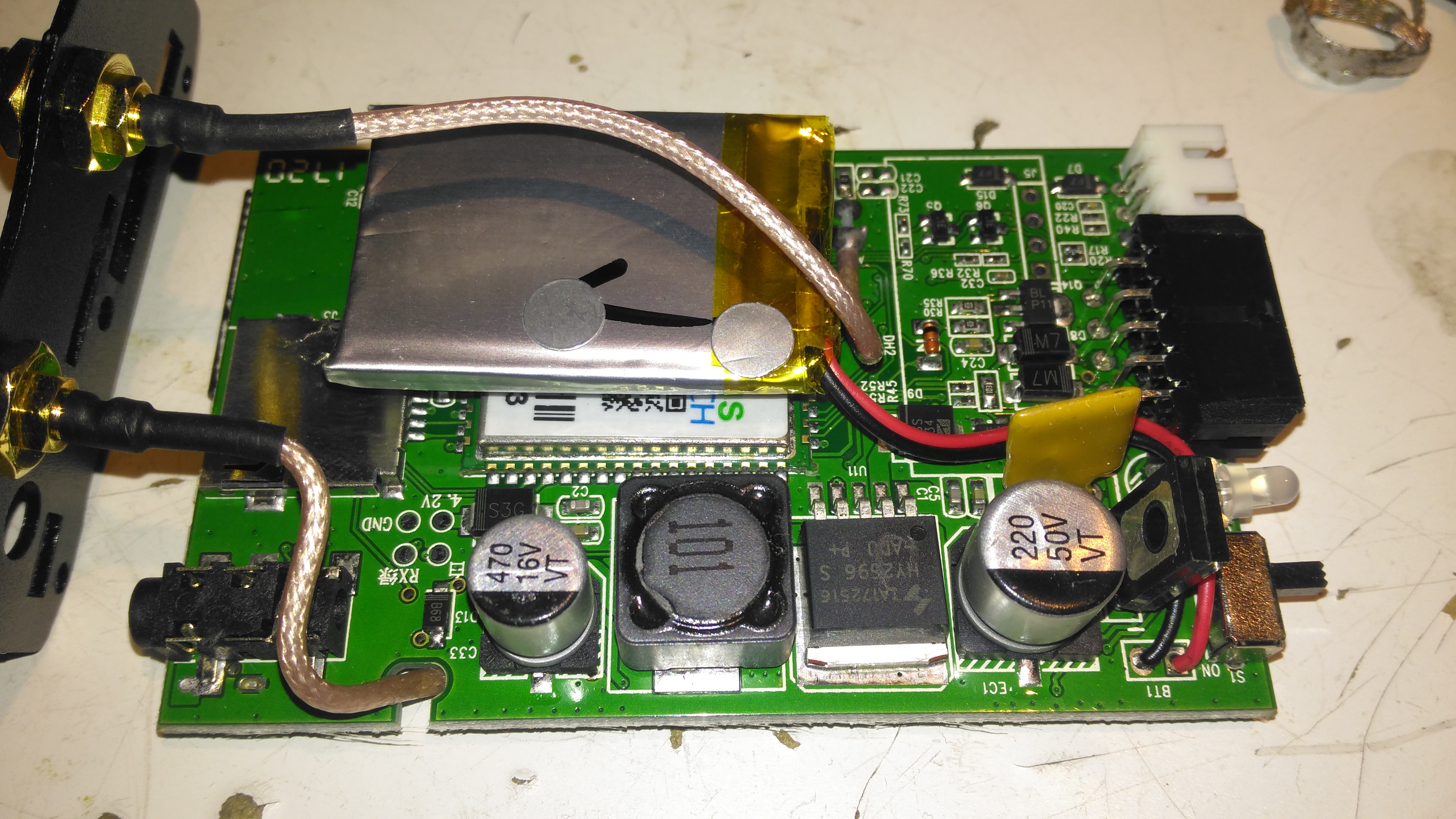
PCB Top
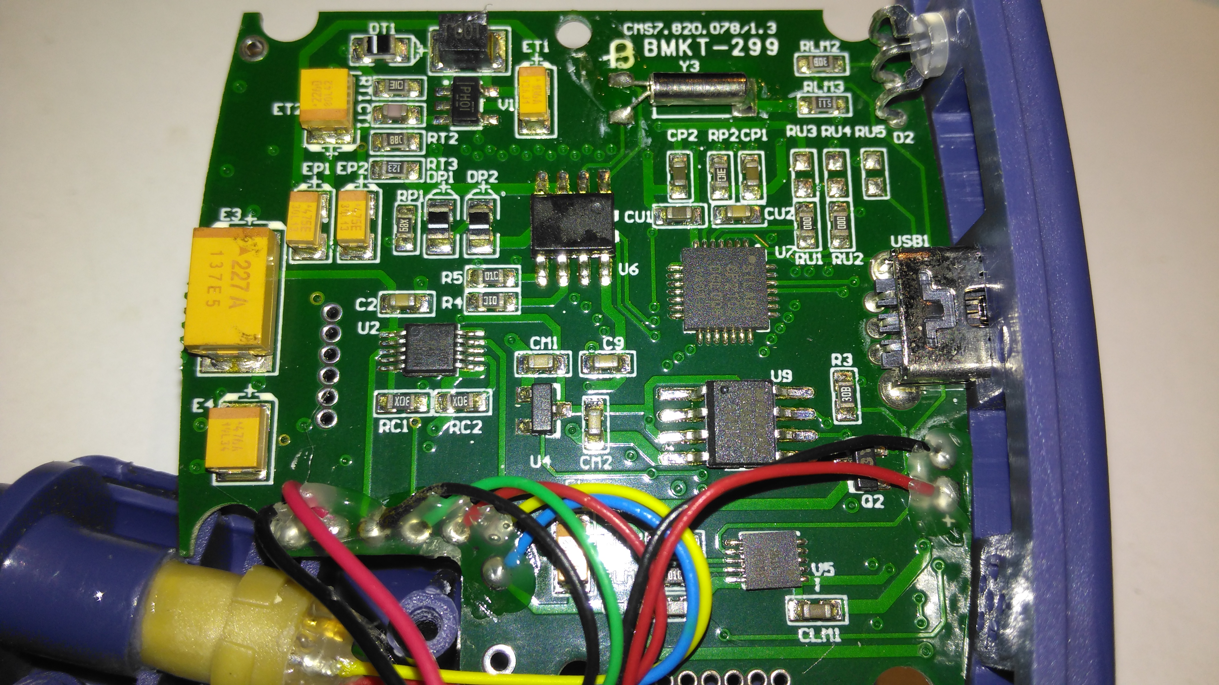
Once the end panel is removed, the PCB just slides out of the aluminium extruded casing. It’s pretty heavily packed with components in here. A switching regulator deals with the 12v input from the vehicle battery, and is protected by a polyfuse on the right. The GSM module is hiding under the Li-Po backup cell, unfortunately the sticky pad used to secure this wouldn’t come off without damaging something. The pigtails for both the GPS & GSM antennas are permanently soldered to the board here.
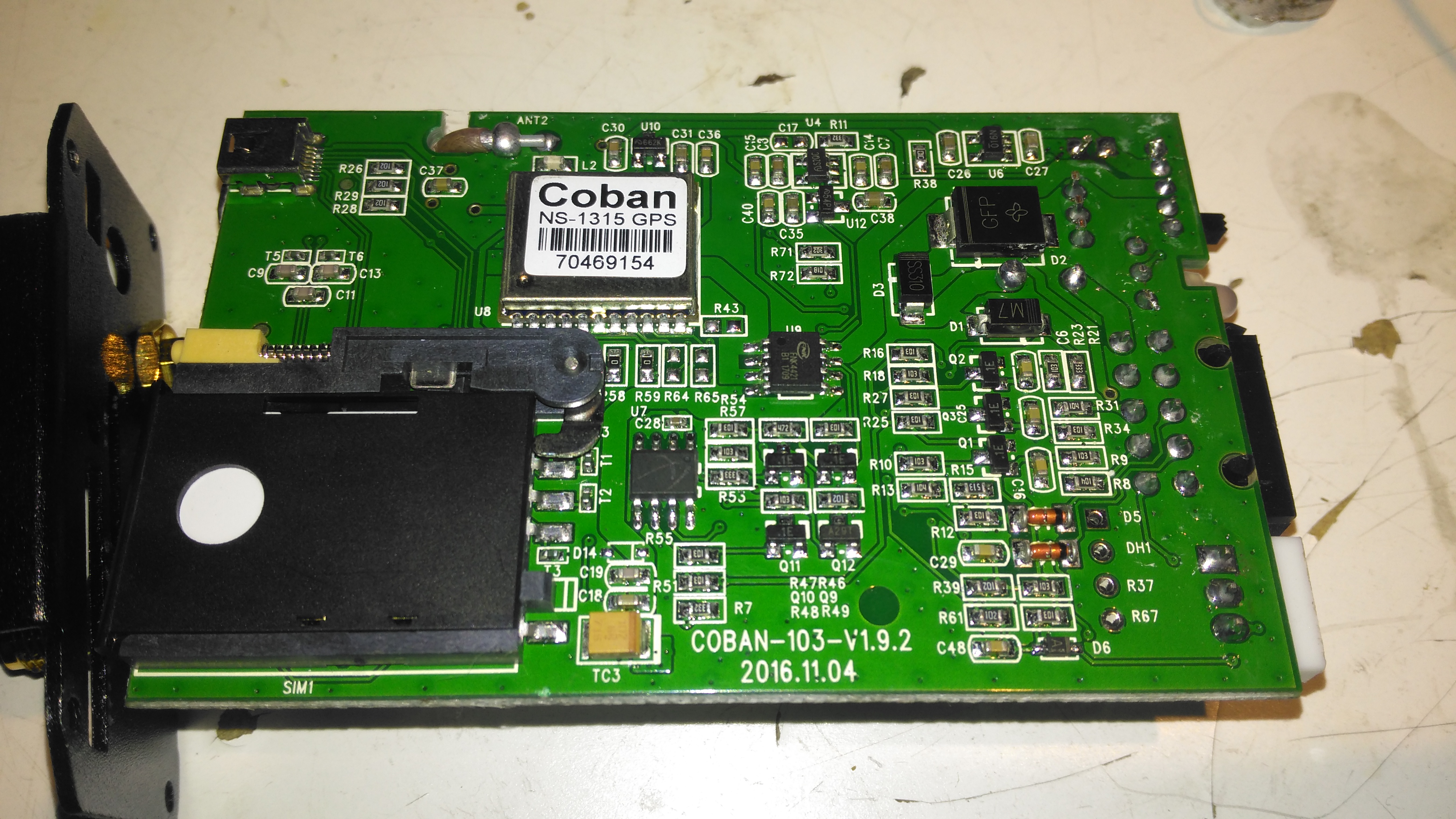
PCB Bottom
The bottom of the PCB has the GPS module, and mainly input protection & bypassing components. There is a FNK4421 Dual P-Channel MOSFET here as well, probably used for switching the external relay or alarm siren. The SIM socket for the GSM modem is located here in the corner.
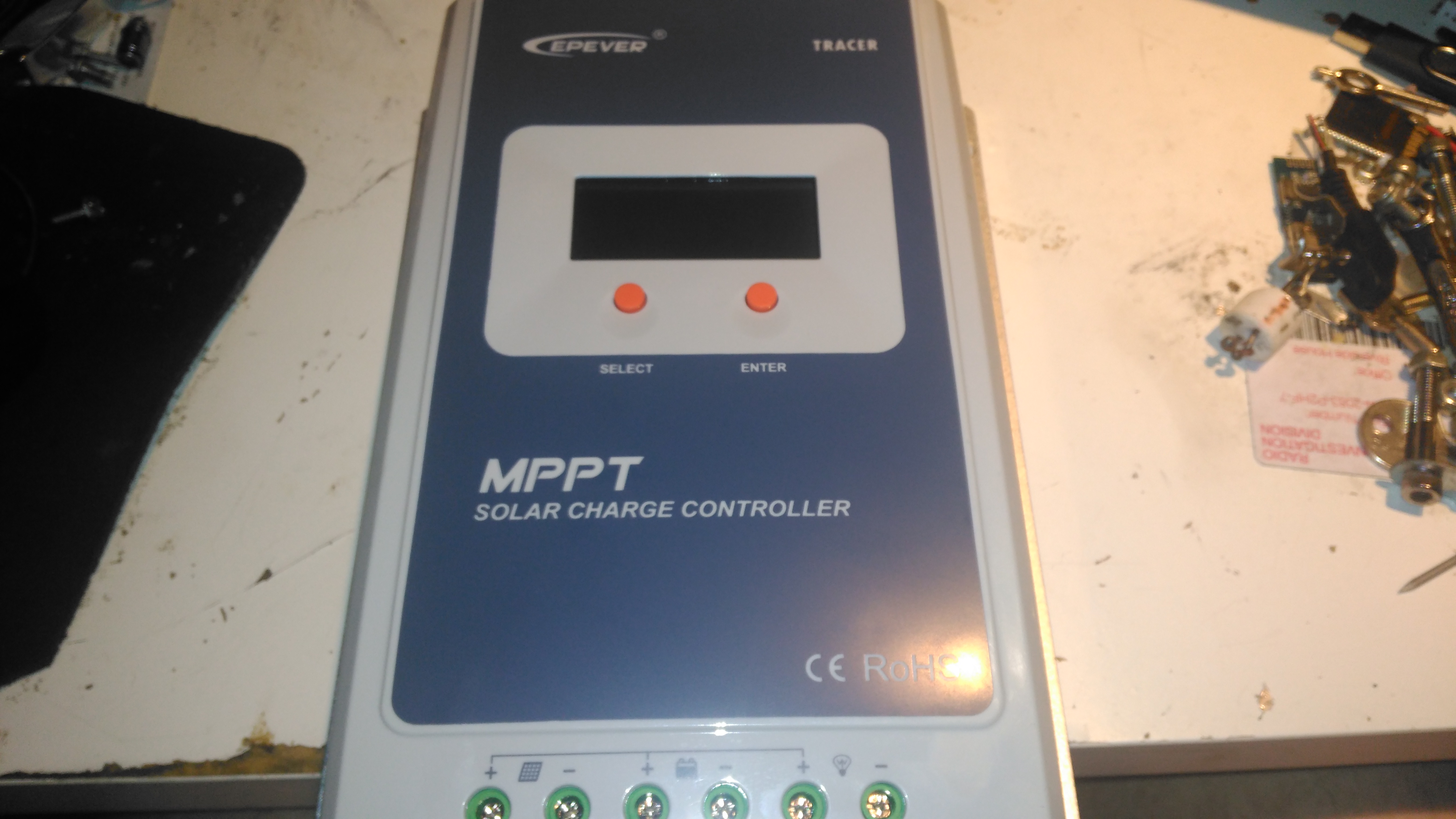
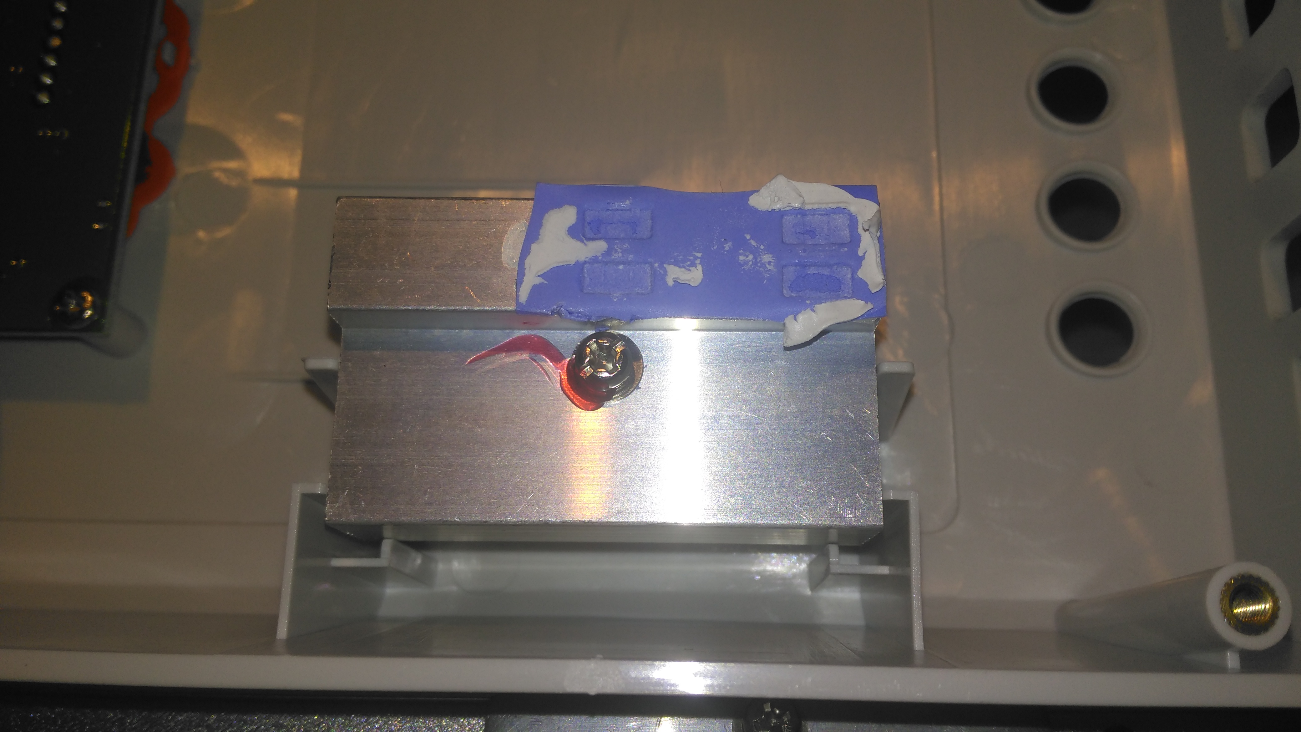
Here’s the solar charge controller to go with the MT50 from the last post. This is the 40A version of the EpEver Tracer A series, the 4210A. This unit is large, and very heavy. Most of this weight comes from the enormous heatsink which doubles as the mounting plate for all the other components, and the large inductors that are going to be required for the DC-DC conversion that MPPT requires.
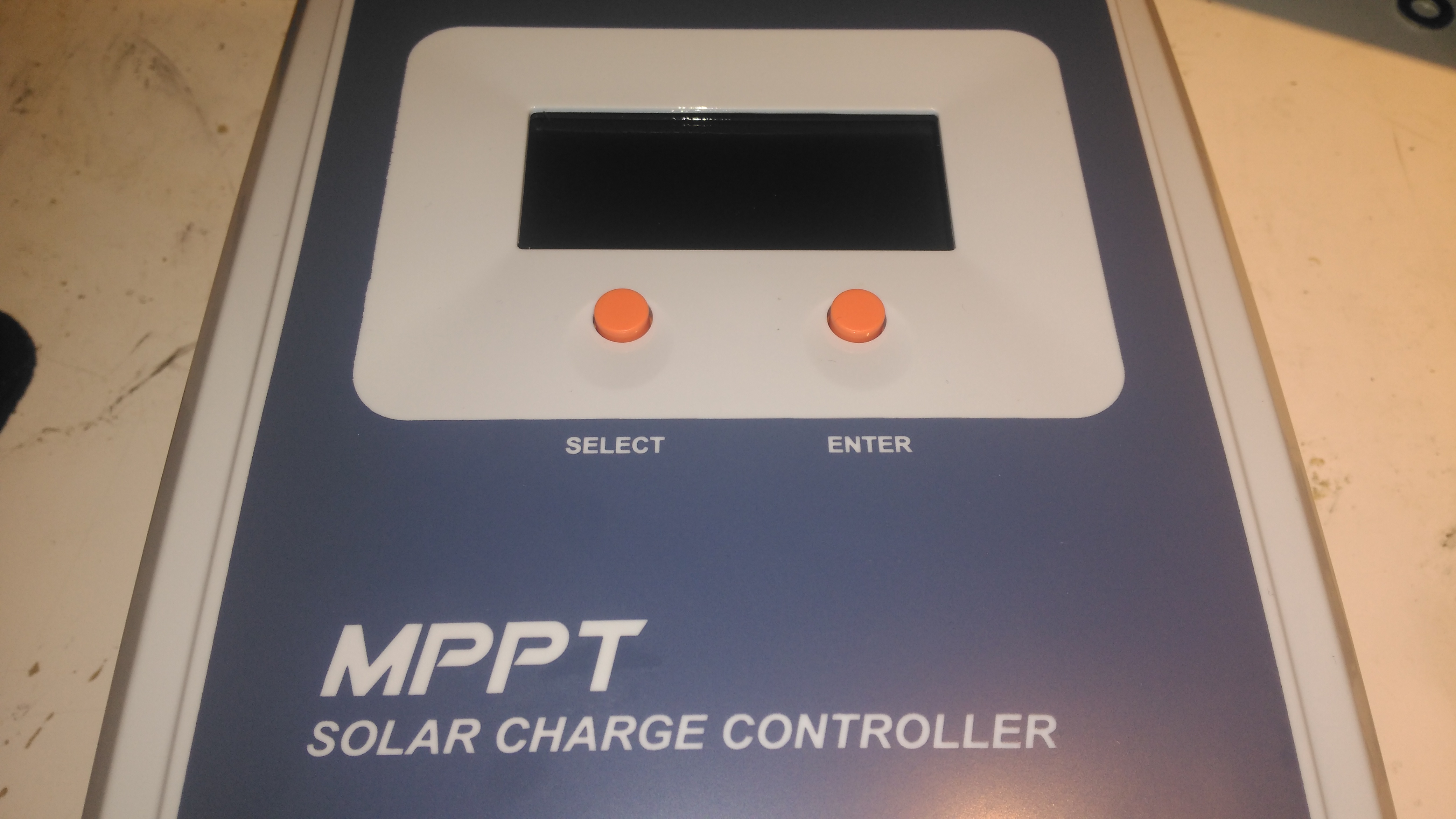
Front Panel
The front panel has a basic LCD, which shows various stats, such as PV Volts & Amps, and battery bank Volts & Amps. The pair of buttons are used to navigate the basic menu to configure some options, along with switching the load terminals ON/OFF.
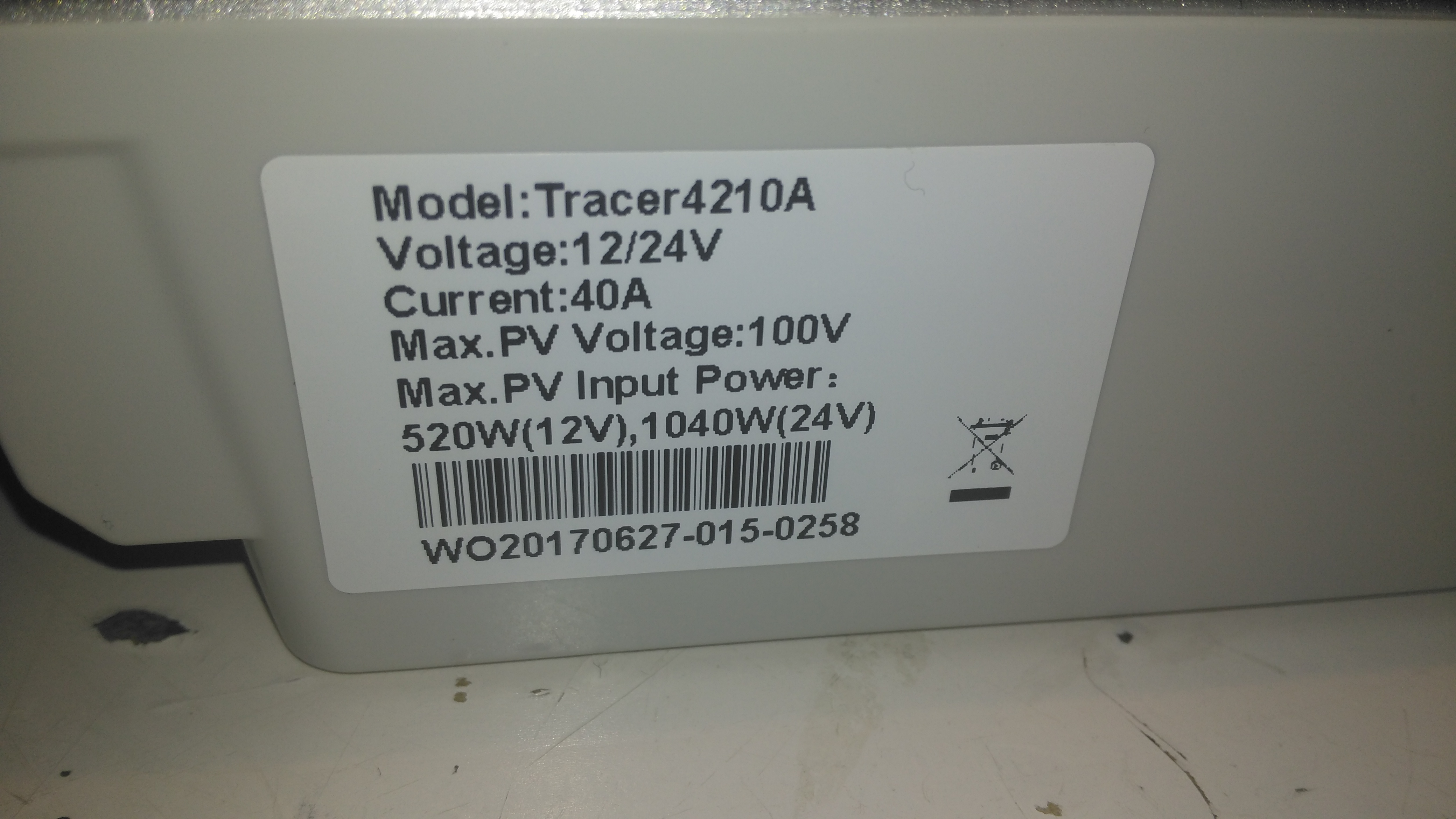
Specifications
There’s a specs label on the top, with a slight difference here vs the manual, which states the max. PV volts as 92v.
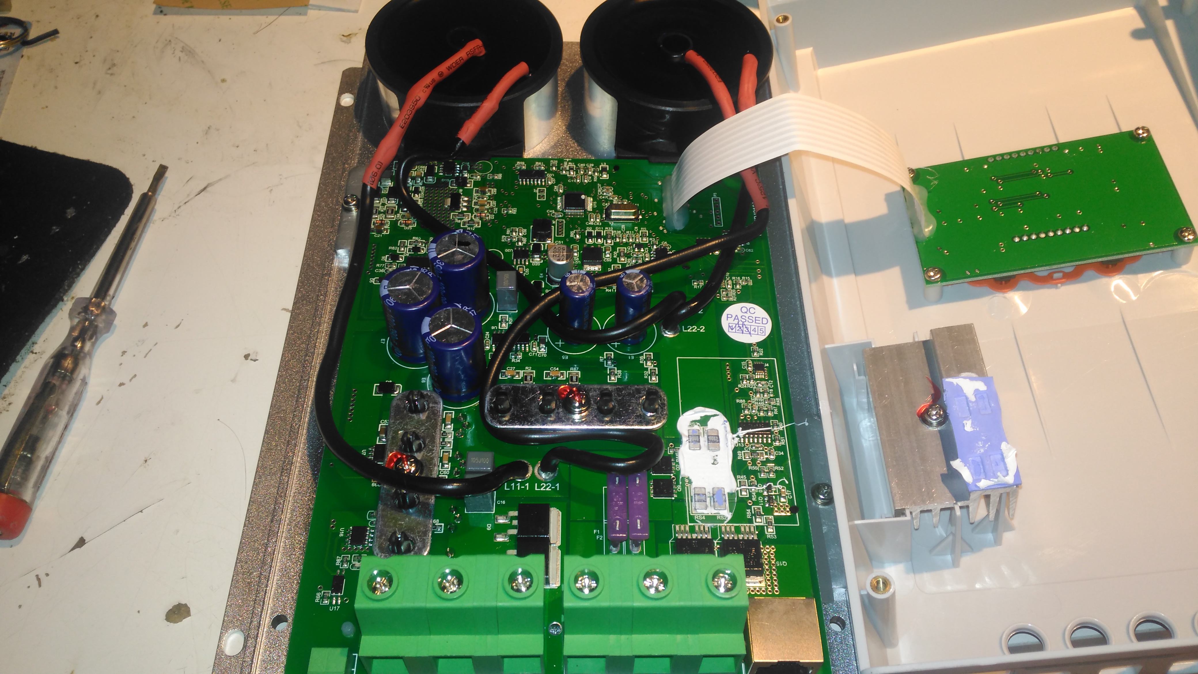
Main PCB Overview
Removing 4 machine screws from the bottom of the unit allows the top to come off. Like the MT50 remote panel, this unit also has moulded-in brass thread inserts in the plastic parts. The PCB in here is heavily comformal coated, which stops me from reading the laser-etched numbers on the semiconductor devices, so there will be few details there.
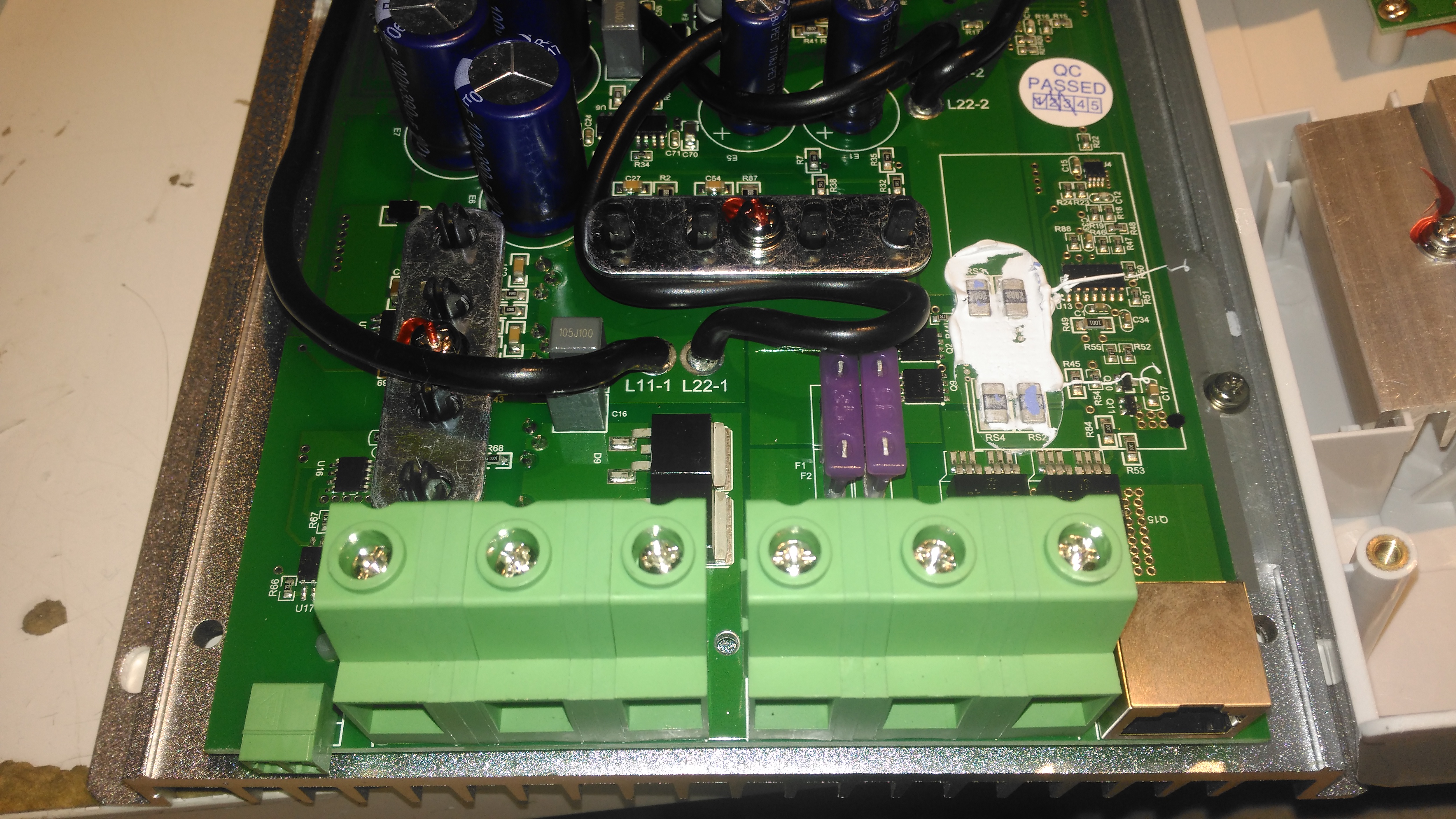
Main PCB Lower
Here’s the bottom section of the main PCB, with the enormous screw terminals, which will easily take cables up to about 16mm². The RJ-45 jack which hosts the unit’s RS-485 bus is to the right, and a smaller 2-pin connector on the left sorts out the battery temperature sensor.
The DC output MOSFET switches are hiding just behind the right-hand terminals, there’s a pair of them in this unit to handle the output current. Some beefy diodes polarity-protect both the battery & PV inputs.
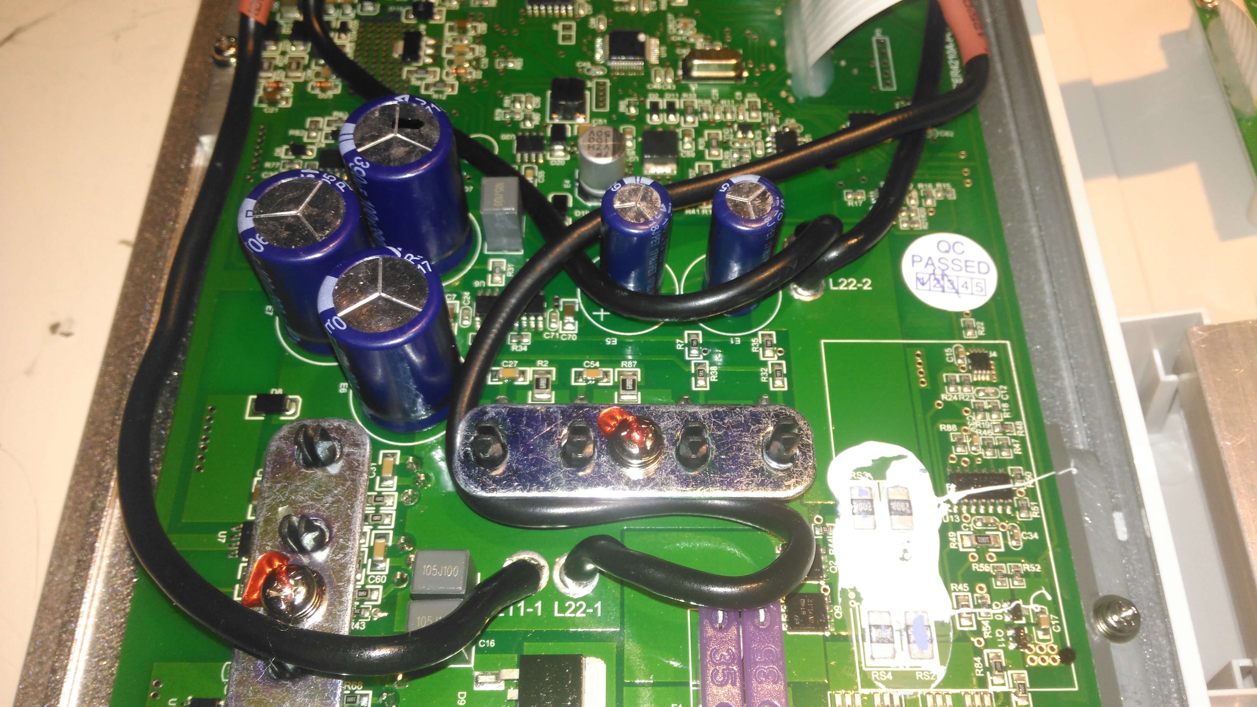
Board Centre
Moving up the board shows two 35A automotive blade fuses soldered into the board – these would be a real pain to replace if they ever blew, however with the electronic load current protection built into this unit, it’s an unlikely situation, unless something went hideously wrong. The main switching devices for the DC-DC converter are hidden – they’re clamped to the heatsink with the bars at right angles in the photo, I’m not going to dig any deeper into this just for those though – they’re just TO220 devices.
Under a load of thermal gunk on the right are 4 current shunt resistors, and the amplifiers for reading their values. These 1206-size SMD resistors looked a bit small for the power rating to me, but they’re heatsinked in operation to a small heatsink mounted in the top cover.
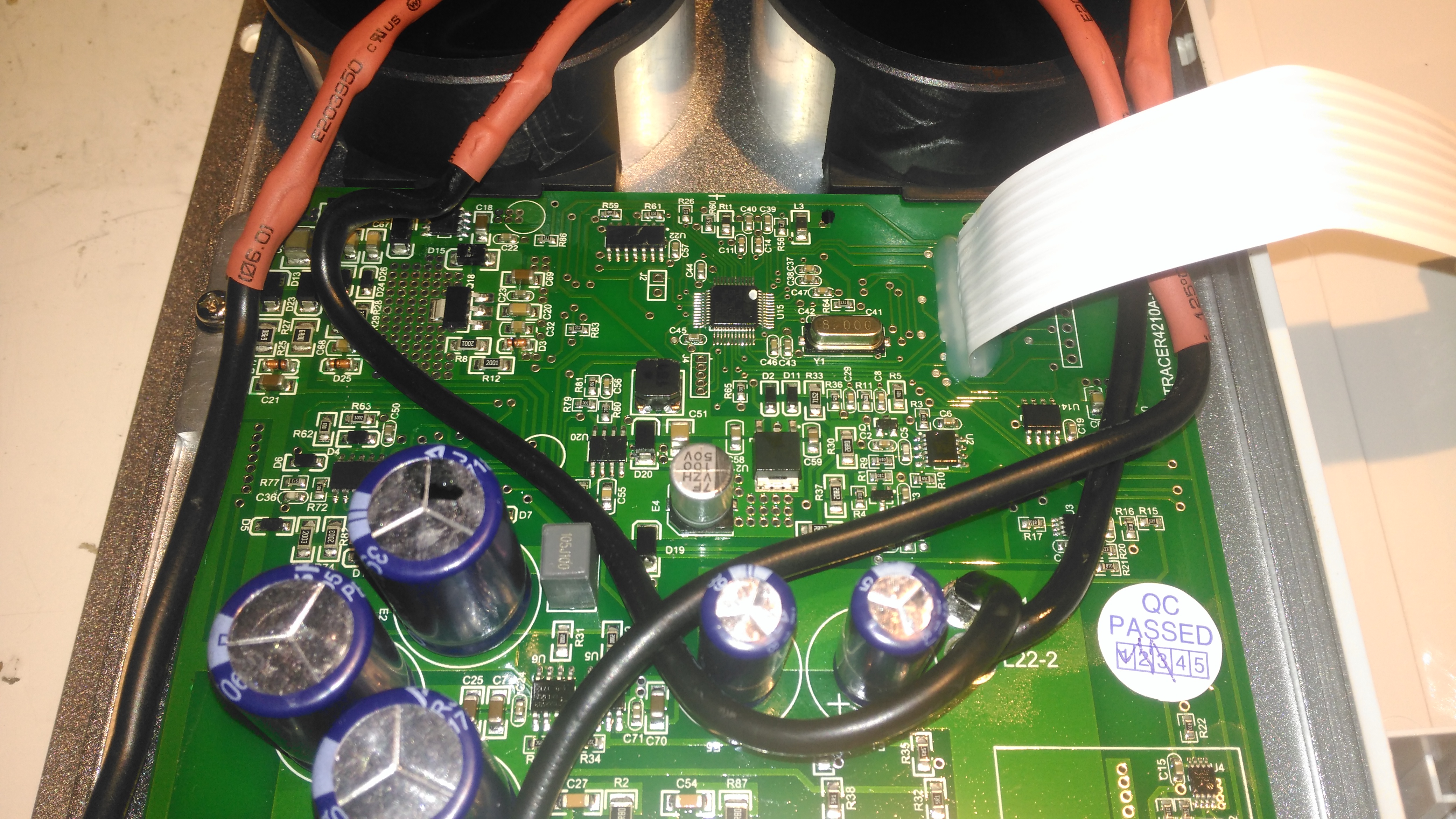
Board Upper
The upper section of the PCB hosts the main microcontroller, and the connections over to the front panel LCD & buttons. Couldn’t really get much info from these chips, due to the conformal coating.
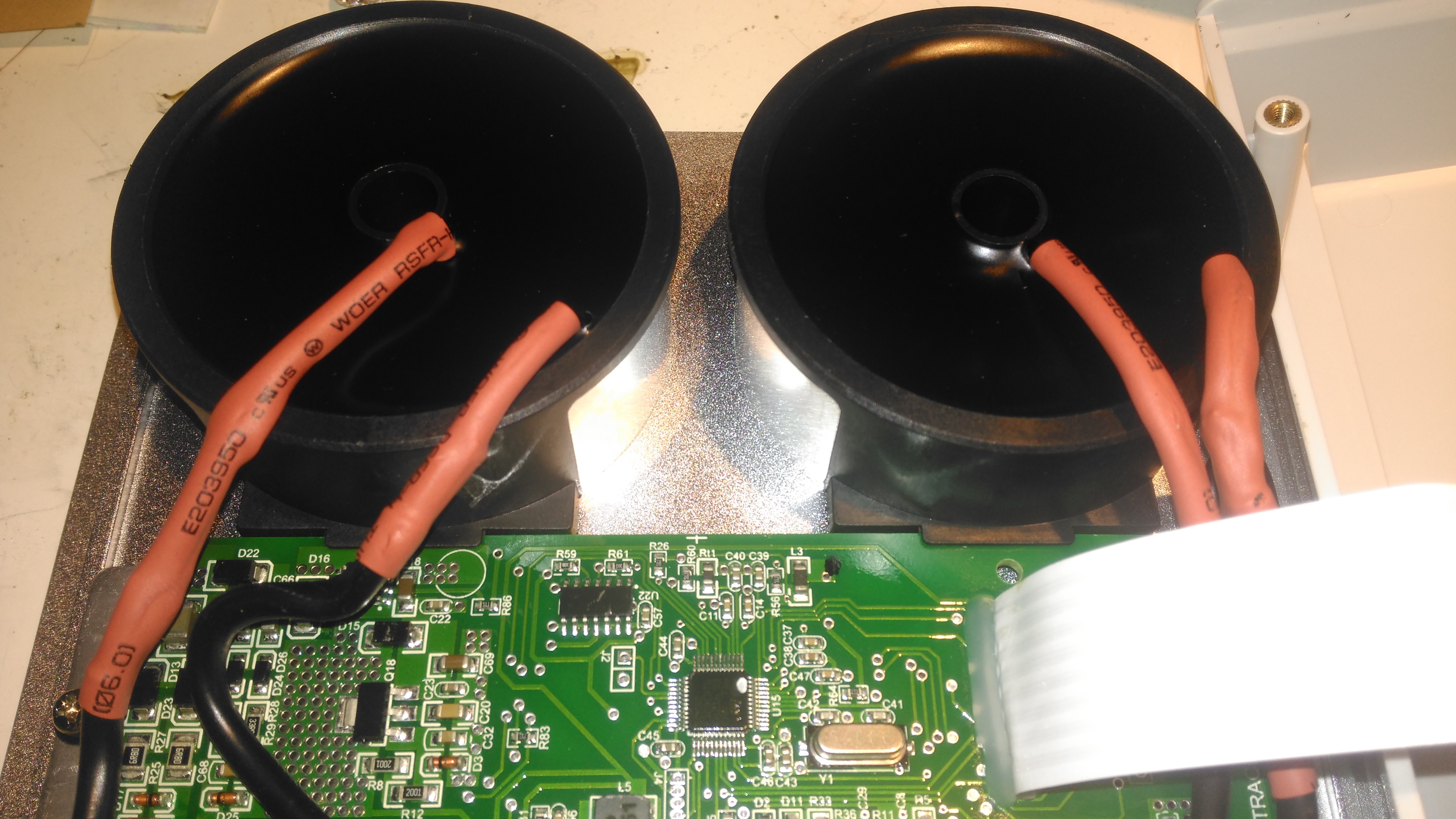
Toroidal Inductors
Right at the top of the unit are these toroidal inductors, potted into aluminium housings. The copper windings of these is very heavy – at least 2.5mm². They’re electrically in parallel, the 20A version would only have a single inductor.
Current Shunt Heatsink
This small heatsink sits inside the top cover, and provides some cooling to the current shunts.
Display Board
Not much to say for the display board, there’s going to be nothing here apart from an I²C LCD driver & the pair of front panel buttons, so I won’t bother removing this from the case.
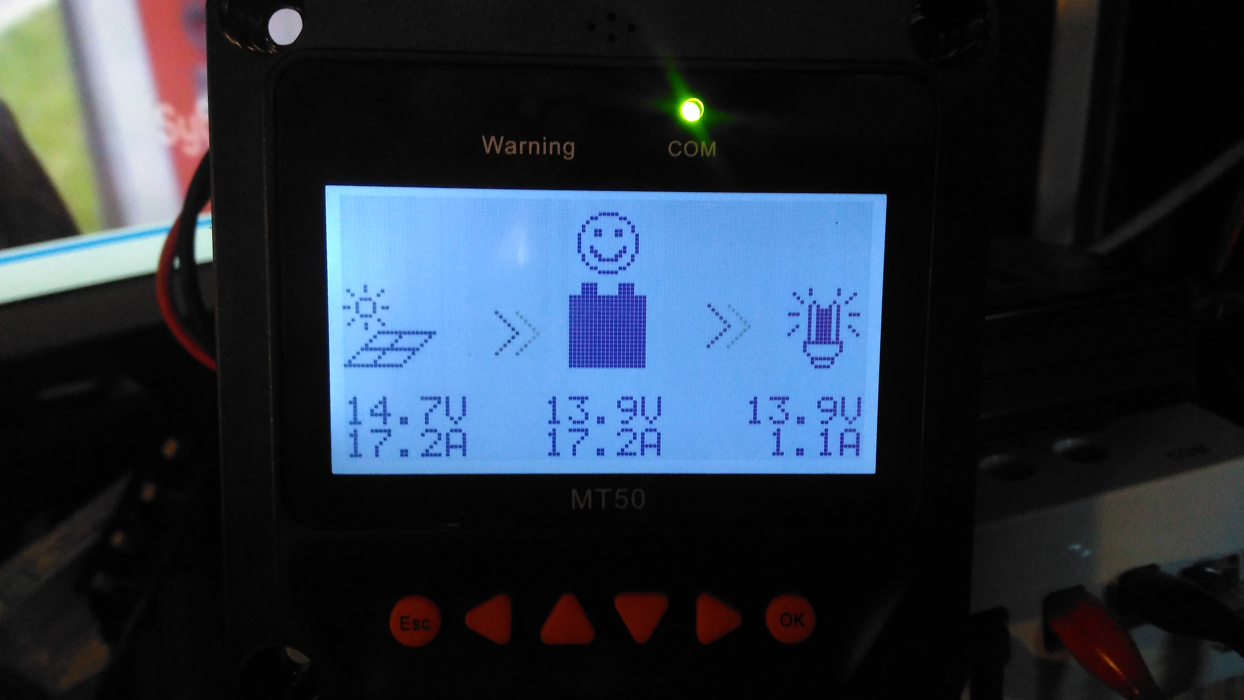
Here’s the MT50 controller from EpEver, that interfaces with it’s Tracer MPPT solar charge controllers, and gives access to more programming options on the charge controllers, without the need for a laptop. The display is a large dot-matrix unit, with built in backlight. Above is the display on the default page, showing power information for the entire system.
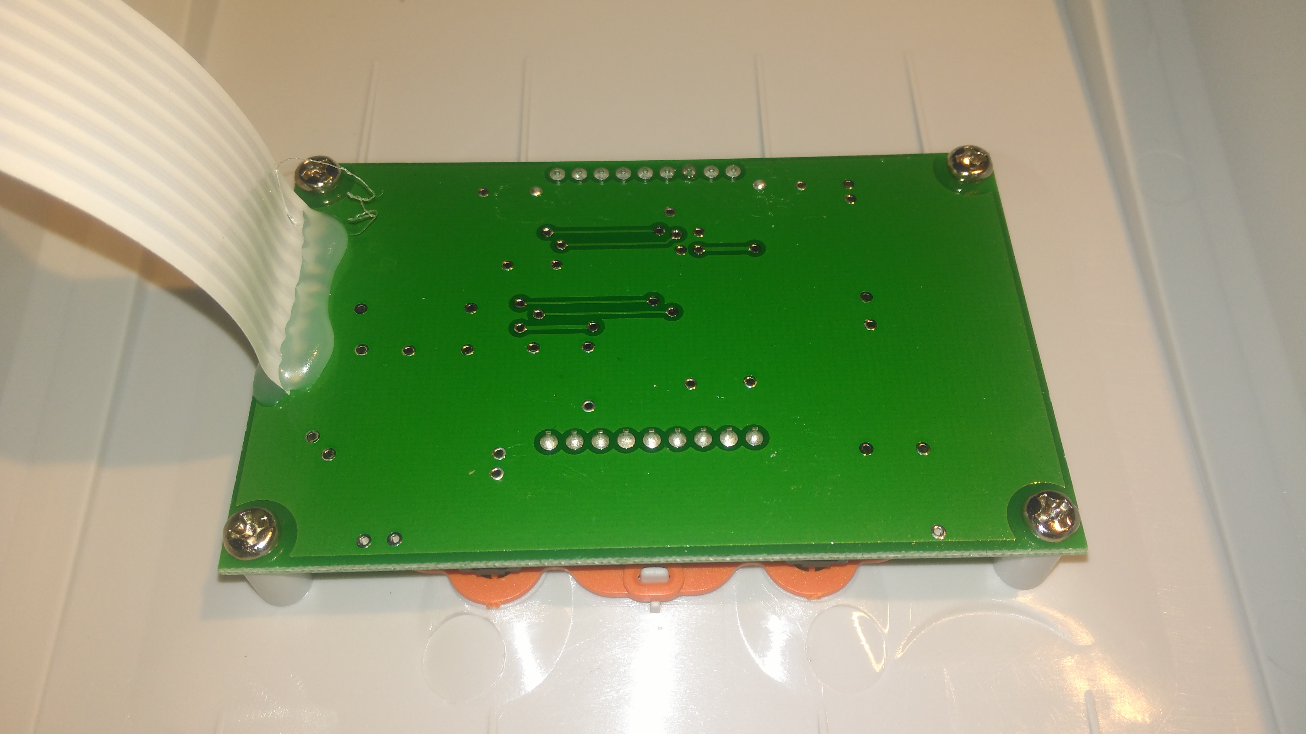
PCB Rear
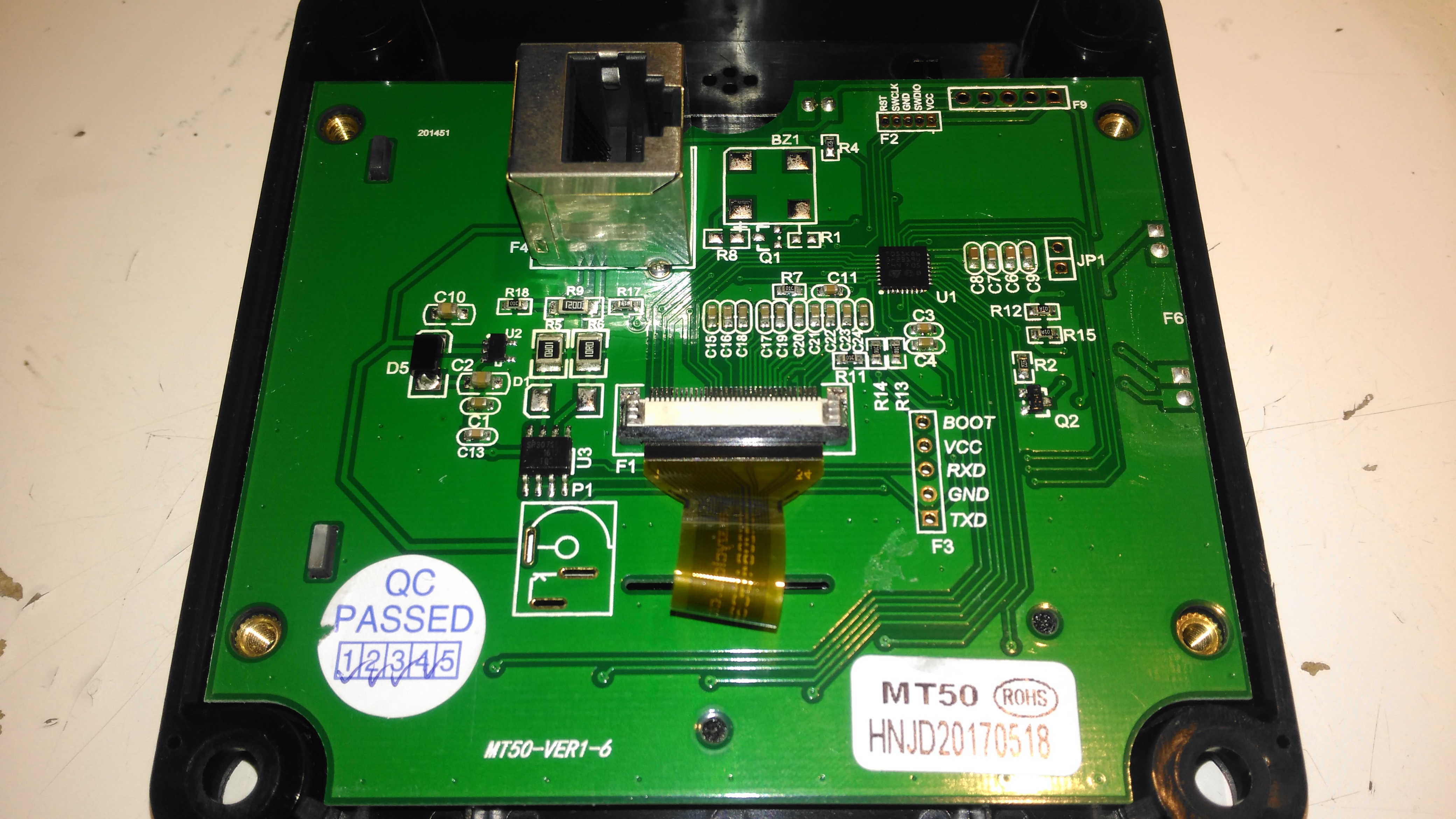
The rear plastic cover is held in place by 4 machine screws, which thread into brass inserts in the plastic frame – nice high quality touch on the design here, no cheap self tapping plastic screws. Both power & data arrive via an Ethernet cable, but the communication here is RS-485, and not compatible with Ethernet! The PCB is pretty sparse, with comms & power on the left, LCD connection in the centre, and the microcontroller on the right.
RS-485 Transceiver
On the left of the board is the RS0485 transceiver, and a small voltage regulator. There’s also a spot for a DC barrel jack, which isn’t included in this model for local power supply.
STM32 Microcontroller
The other side of the board holds the main microcontroller which communicates with the charge controller. This is a STM32F051K8 from ST Microelectronics. With a 48MHz ARM Cortex M0 core, and up to 64K of flash, this is a pretty powerful MCU that has very little to do in this application.
PCB Front
The front of the PCB has the ENIG contacts of the front panel buttons, and the LCD backlight assembly. There’s nothing else under the plastic backlight spreader either.
LCD Rear
The front case holds the LCD module in place with glue, and the rubber buttons are placed underneath, which is heat staked in place.
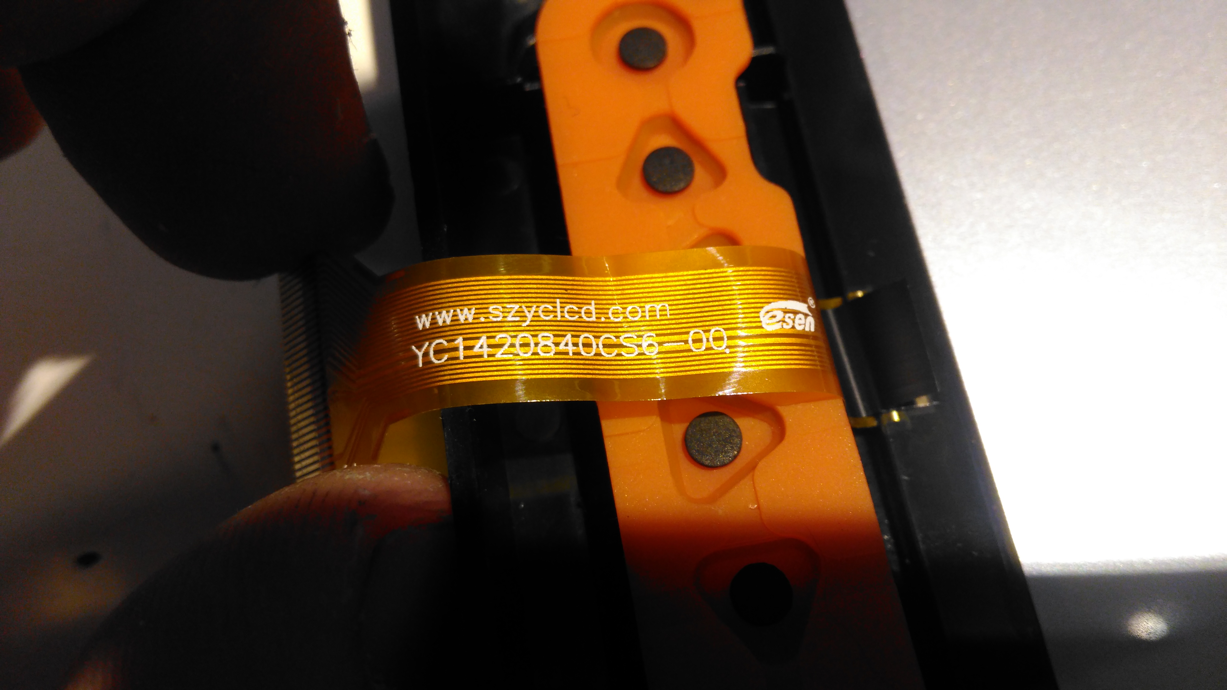
LCD Model
The LCD is a YC1420840CS6 from eCen in China. Couldn’t find much out about this specific LCD.
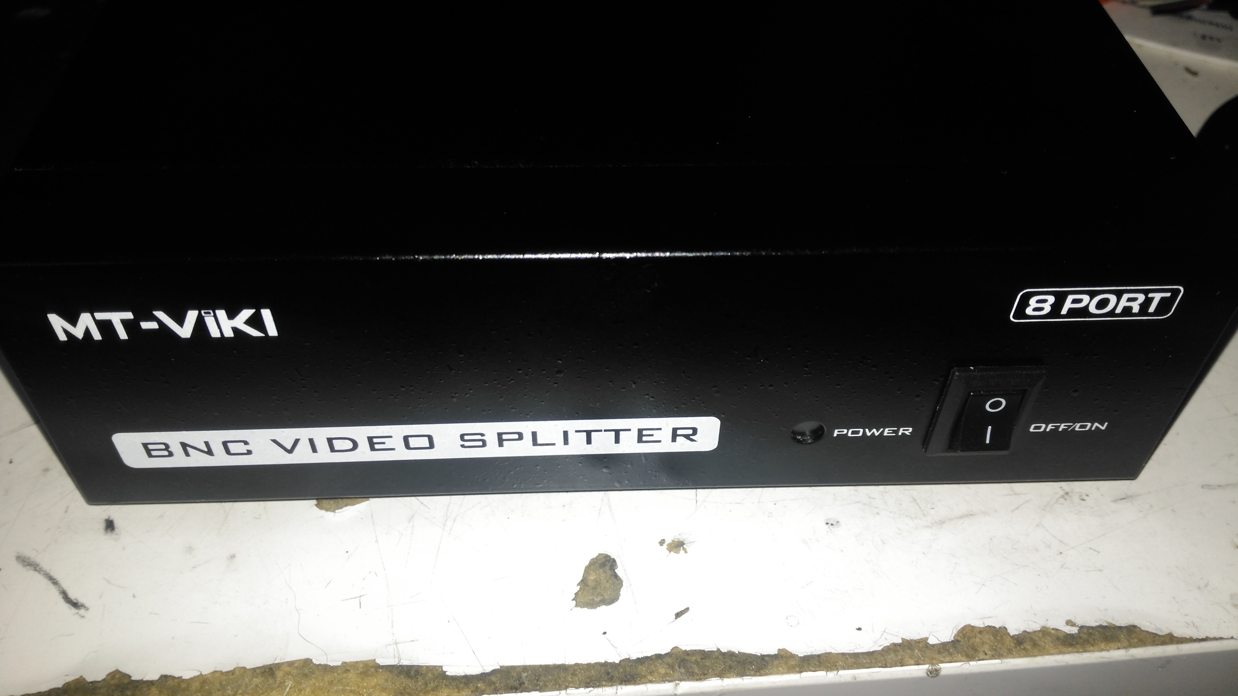
Time for another eBay special: this time it’s an 8-port video distribution amplifier, with BNC connections designed for commercial/industrial equipment. Not much on the front panel above, apart from the power switch & LED.
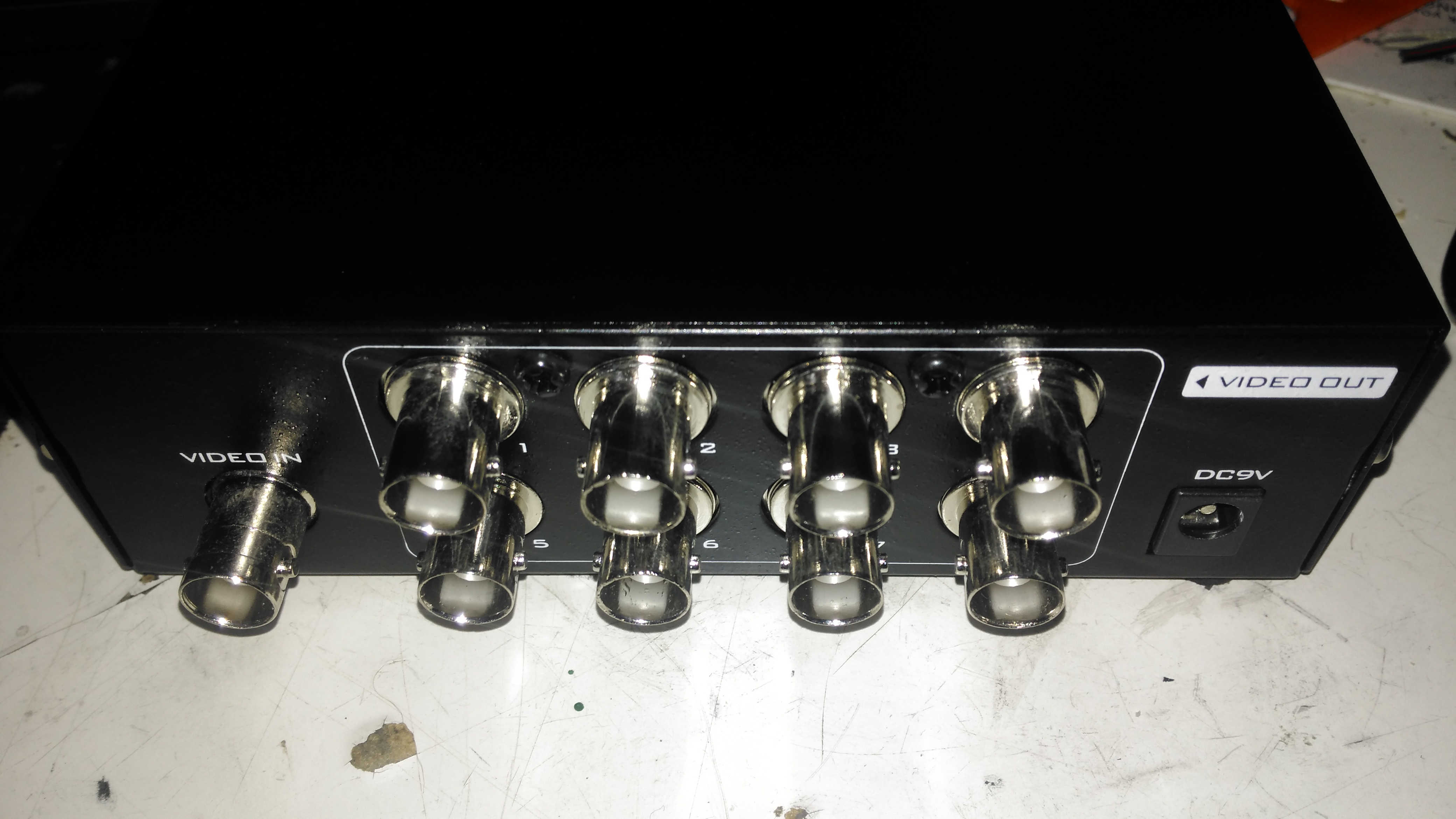
Rear Panel
The rear panel has all the connectors, input is on the left, while the outputs are in the centre. Power is supplied through the barrel jack on the right, 9v DC in this case.
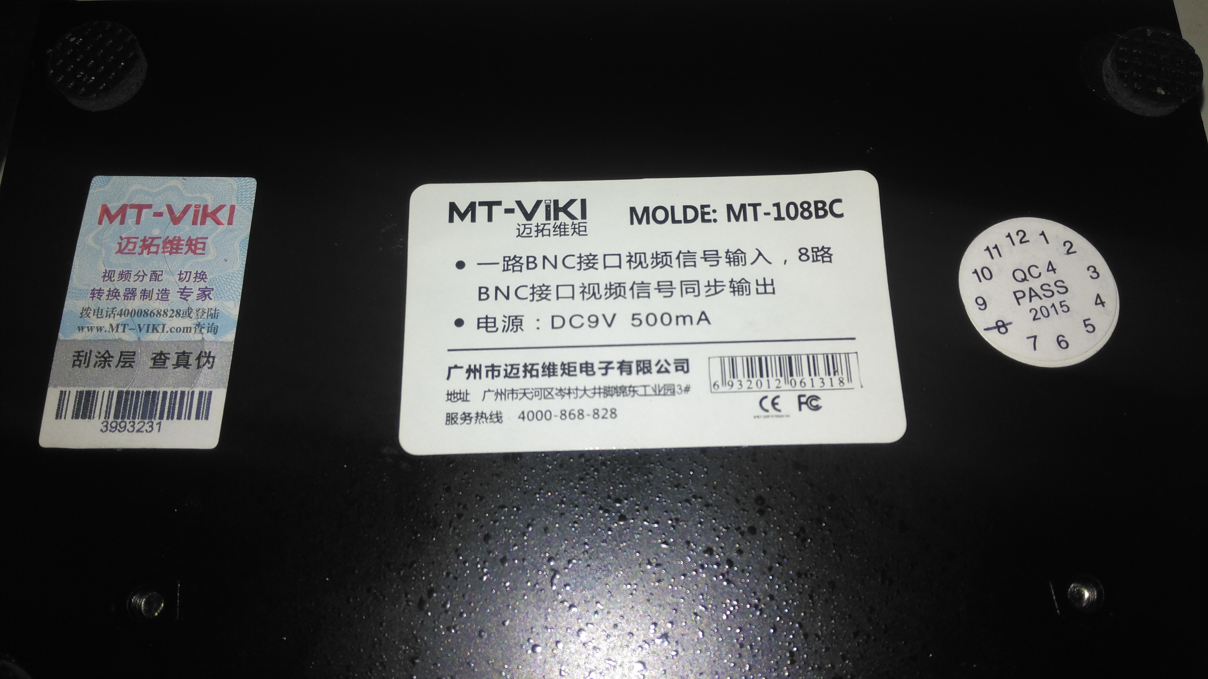
Data Label
Not much in English on the data labels, there’s also an authenticity label on the left to make sure you don’t get a fake.
Amplifier Board
Taking the lid off reveals a very small PCB, taking up less than a third of the aluminium case! The input stage is on the right, composed of a pair of SOT-23 transistors to buffer the incoming signal. There’s an KST812M6 PNP & an S9014 NPN Epitaxial. The signal is then fed to the output stages, all individual S9014 NPN transistors to the output ports.
The power LED is just poking in the general direction of the hole in the front panel, so this isn’t likely to work very well – it’s going to illuminate the inside of the case more!
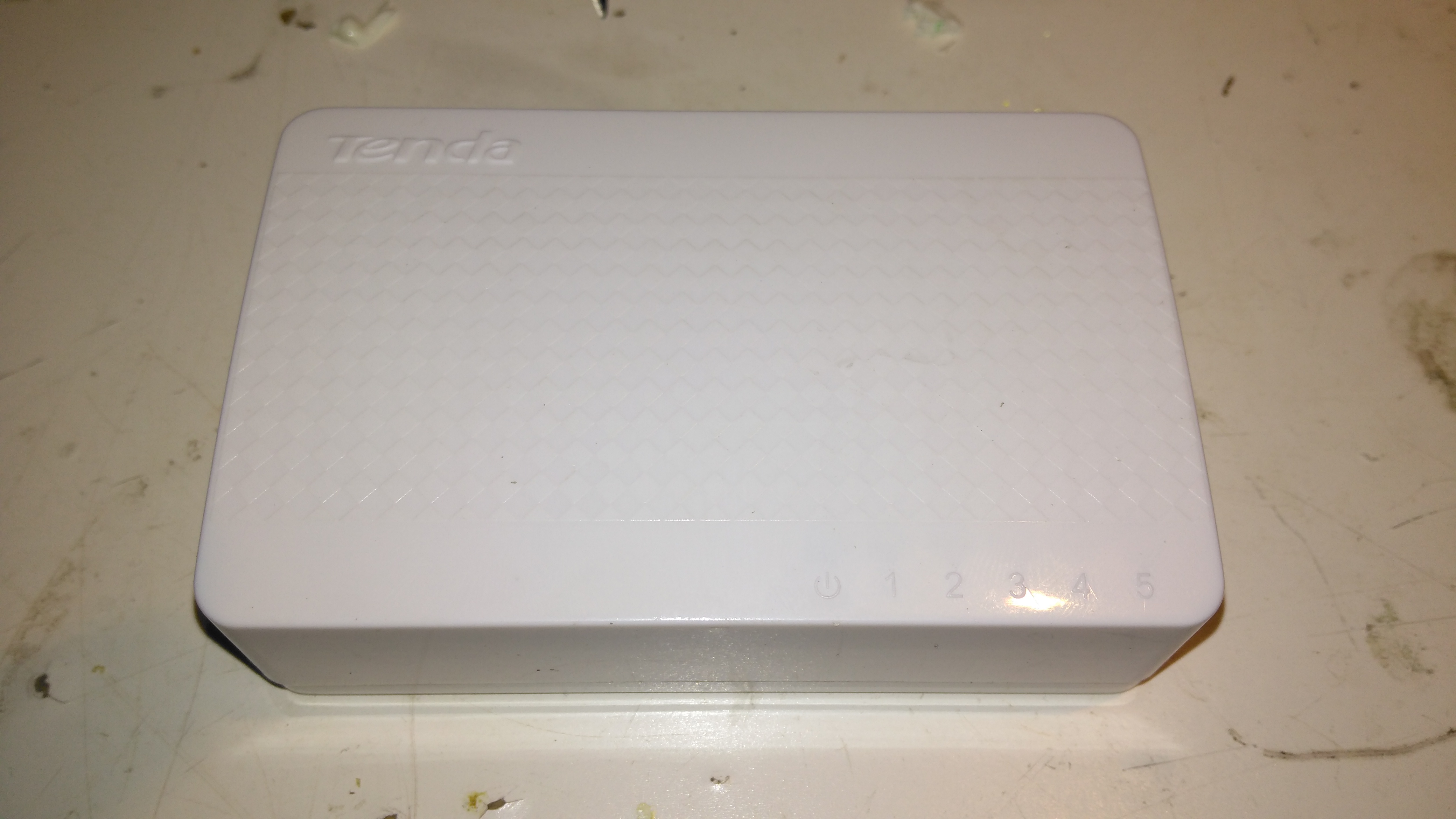
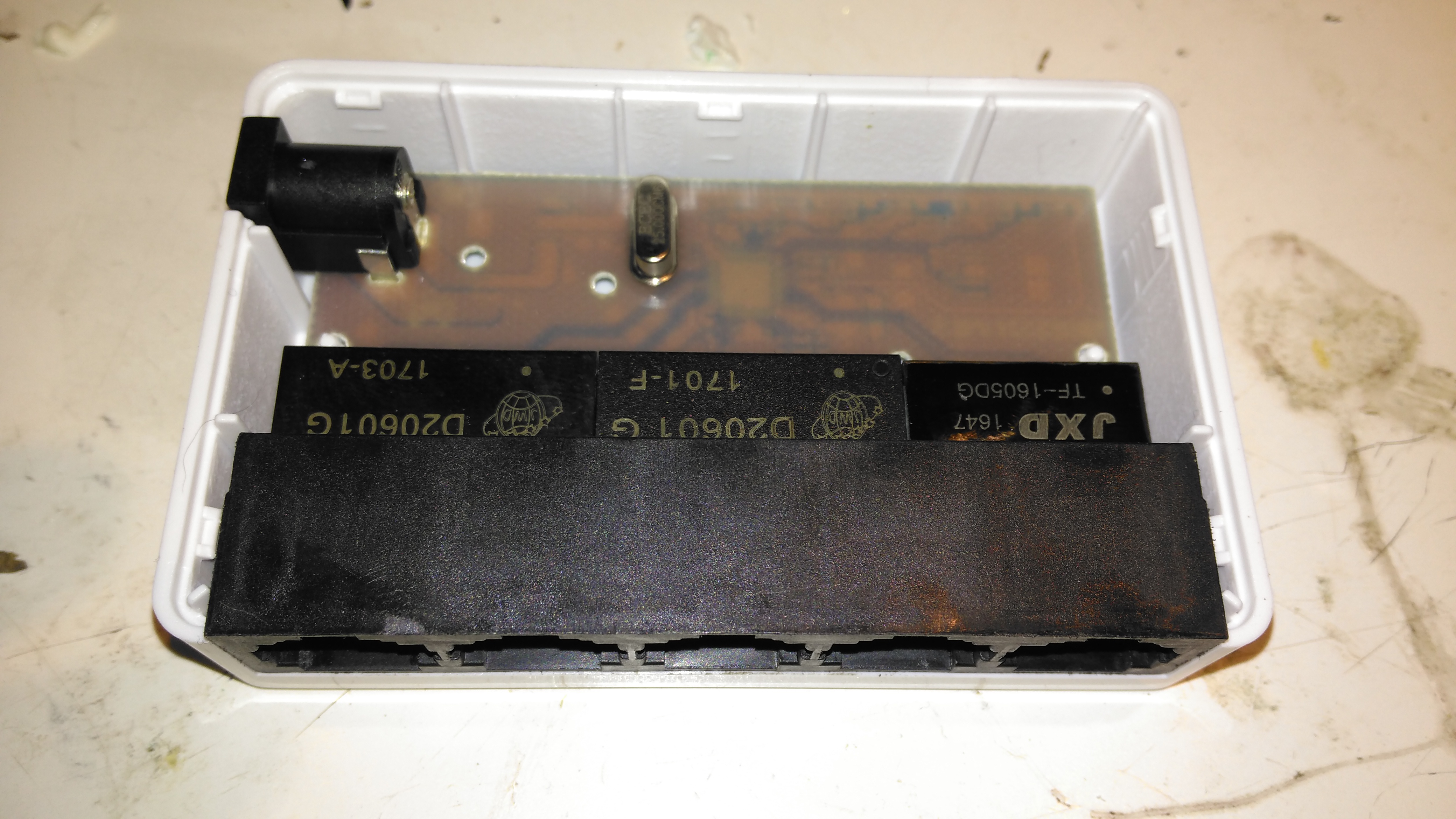
Here’s a tiny ethernet switch from the great fle market that is eBay – the Tenda S105. This unit has 5 ports, but only supports 10/100M. Still, for something so small it’s not bad.
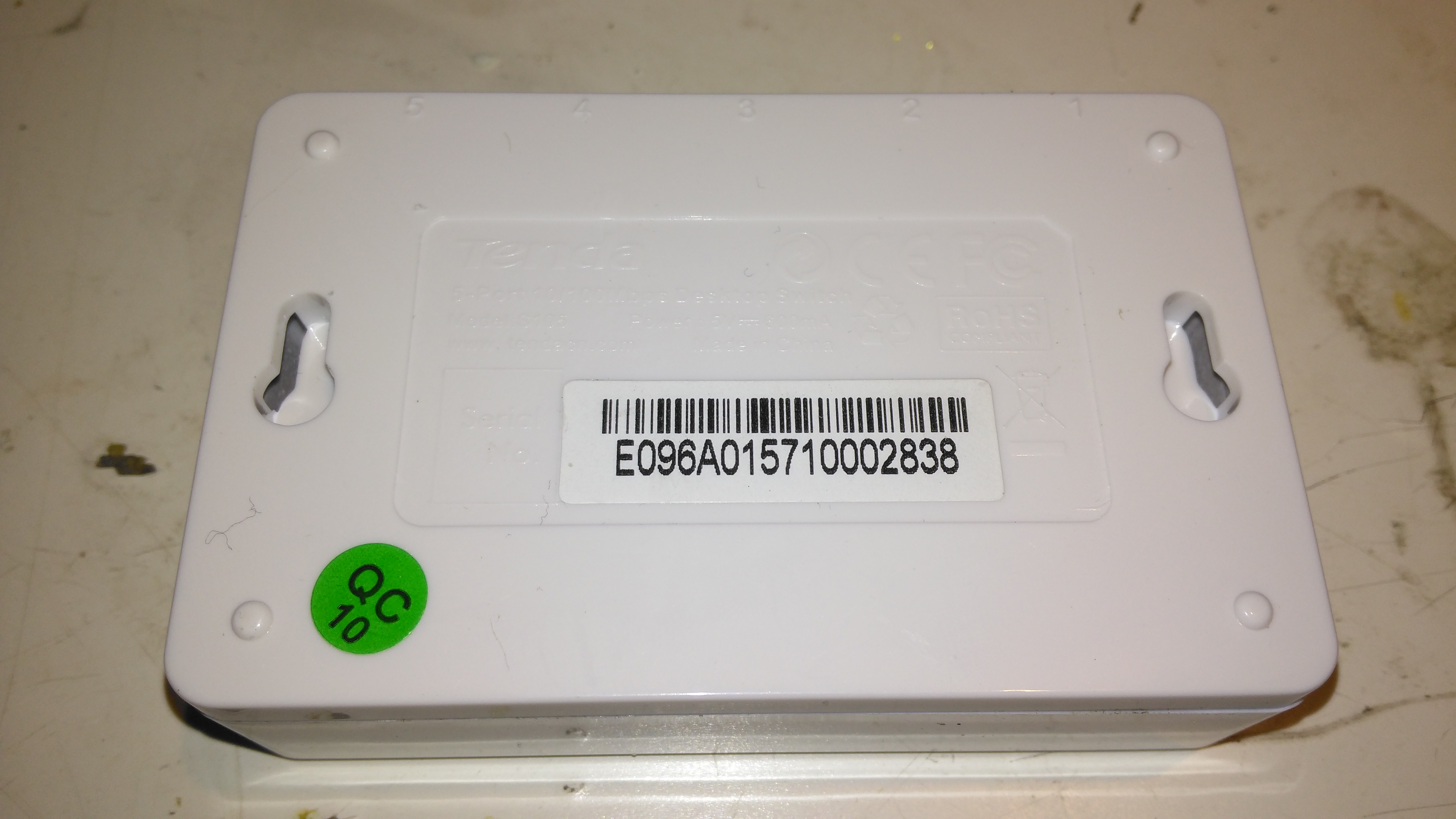
Bottom
Not much on the bottom, there’s a pair of screw hooks for mounting this to a surface.
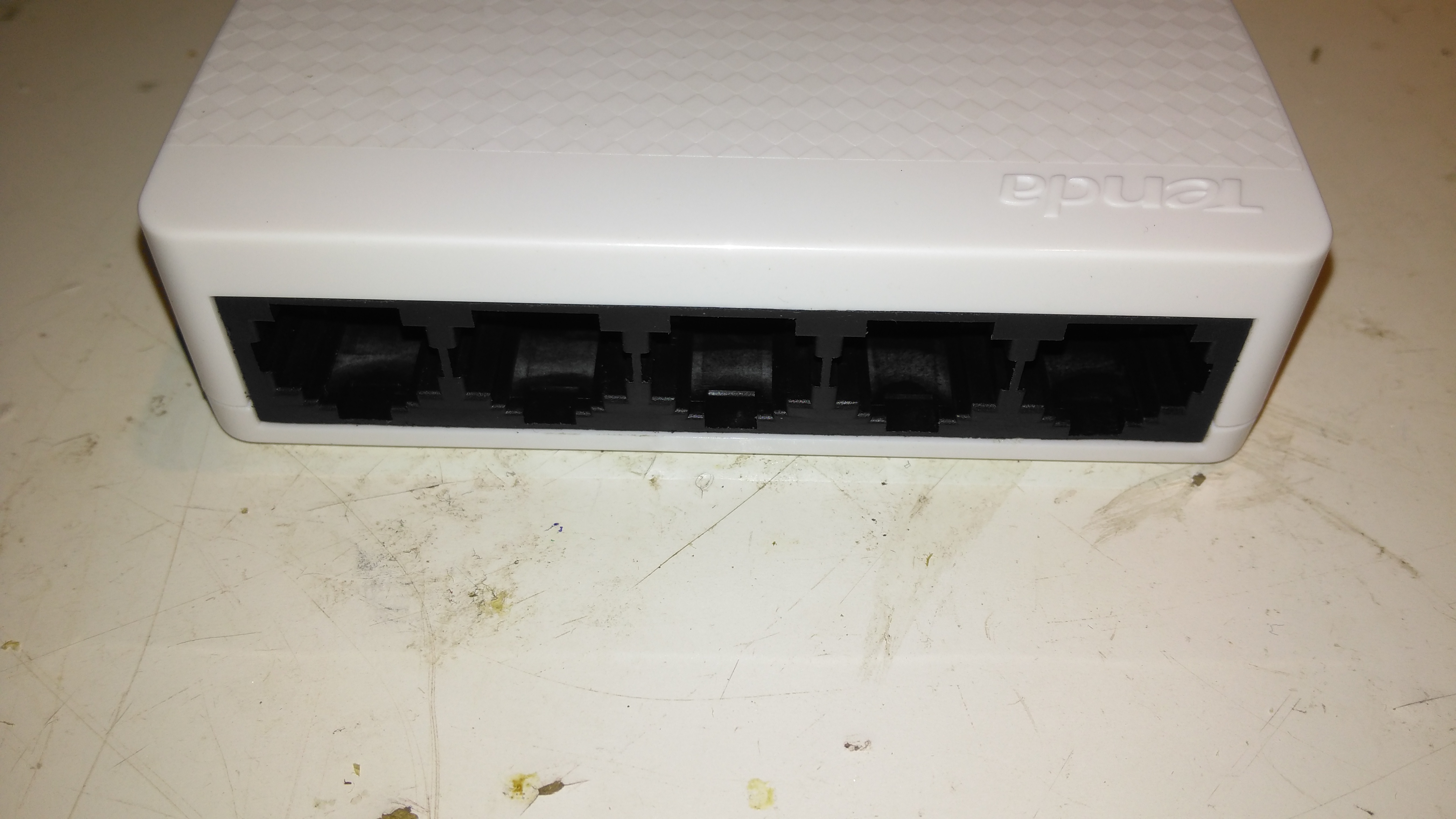
Ports
The 5 ports on the front actually have the pins for the unused pairs of the ethernet cables removed – saving every penny here.
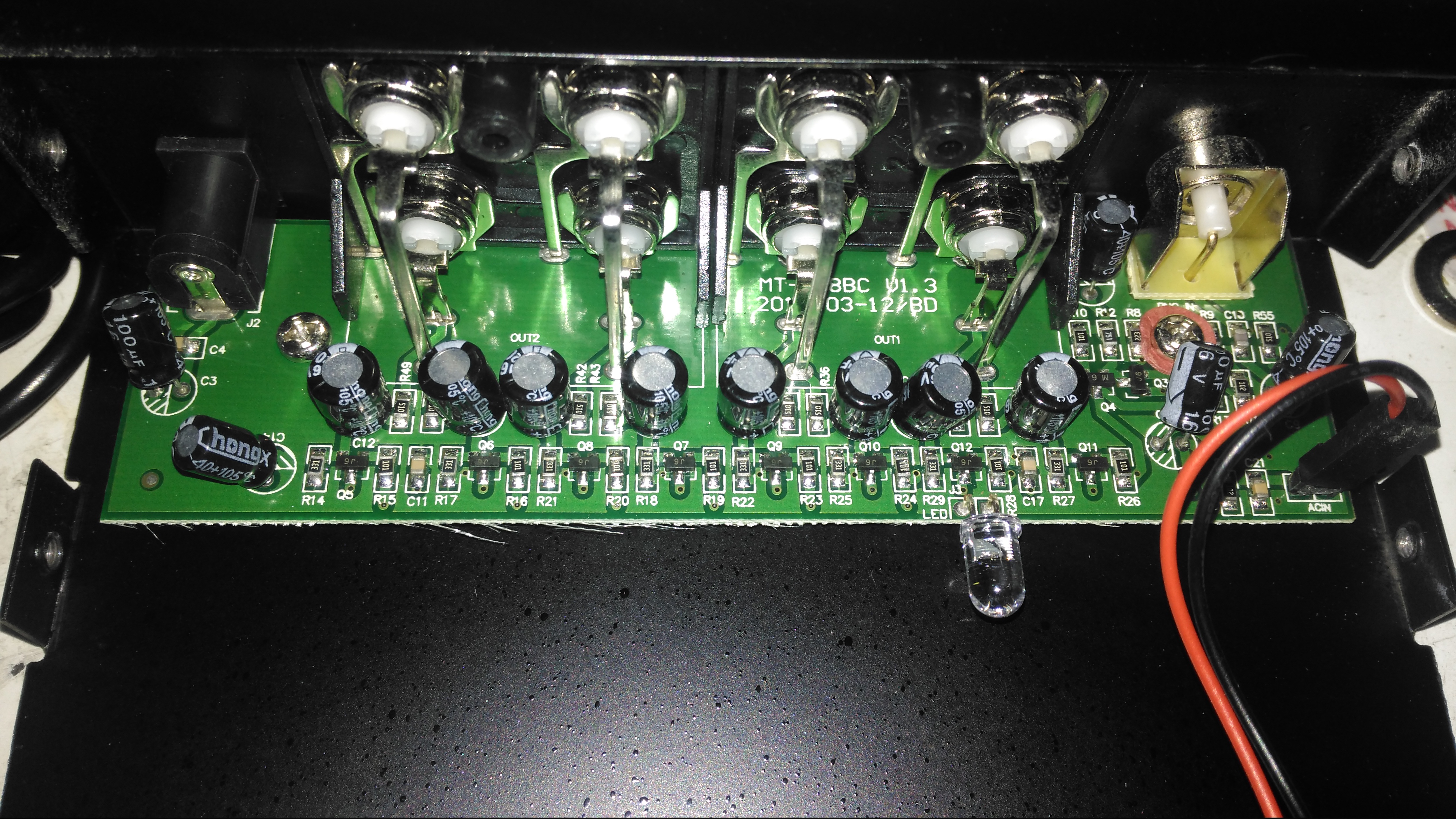
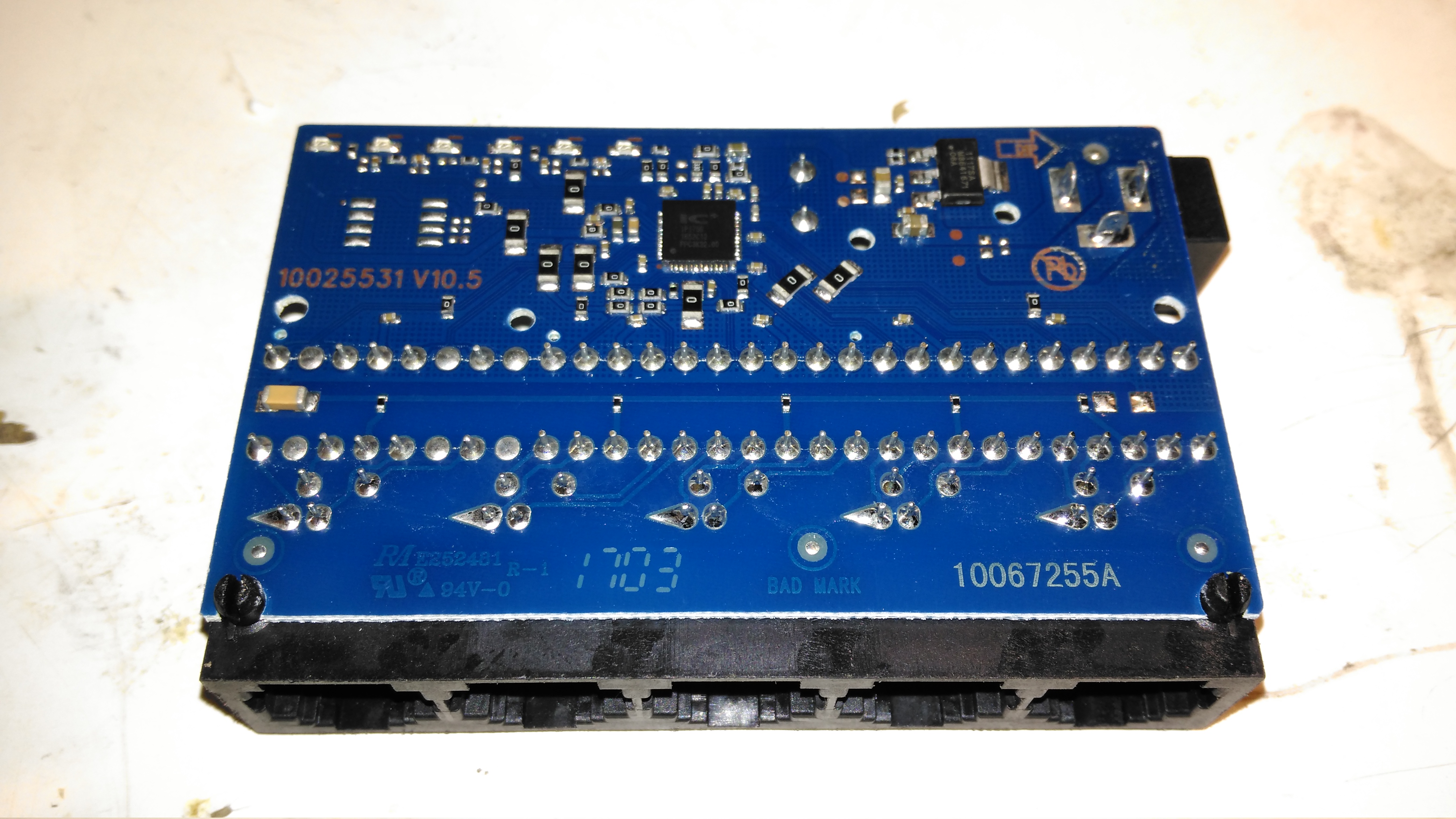
PCB Top
The casing just unclips, revealing the small PCB. Nothing much on the top, just the connectors, isolating transformers & the crystal for the switch IC.
PCB Bottom
The bottom of the PCB is a little more busy, mainly with decoupling components. There’s a 3.3v linear regulator to step down the 5v input for the switch IC.
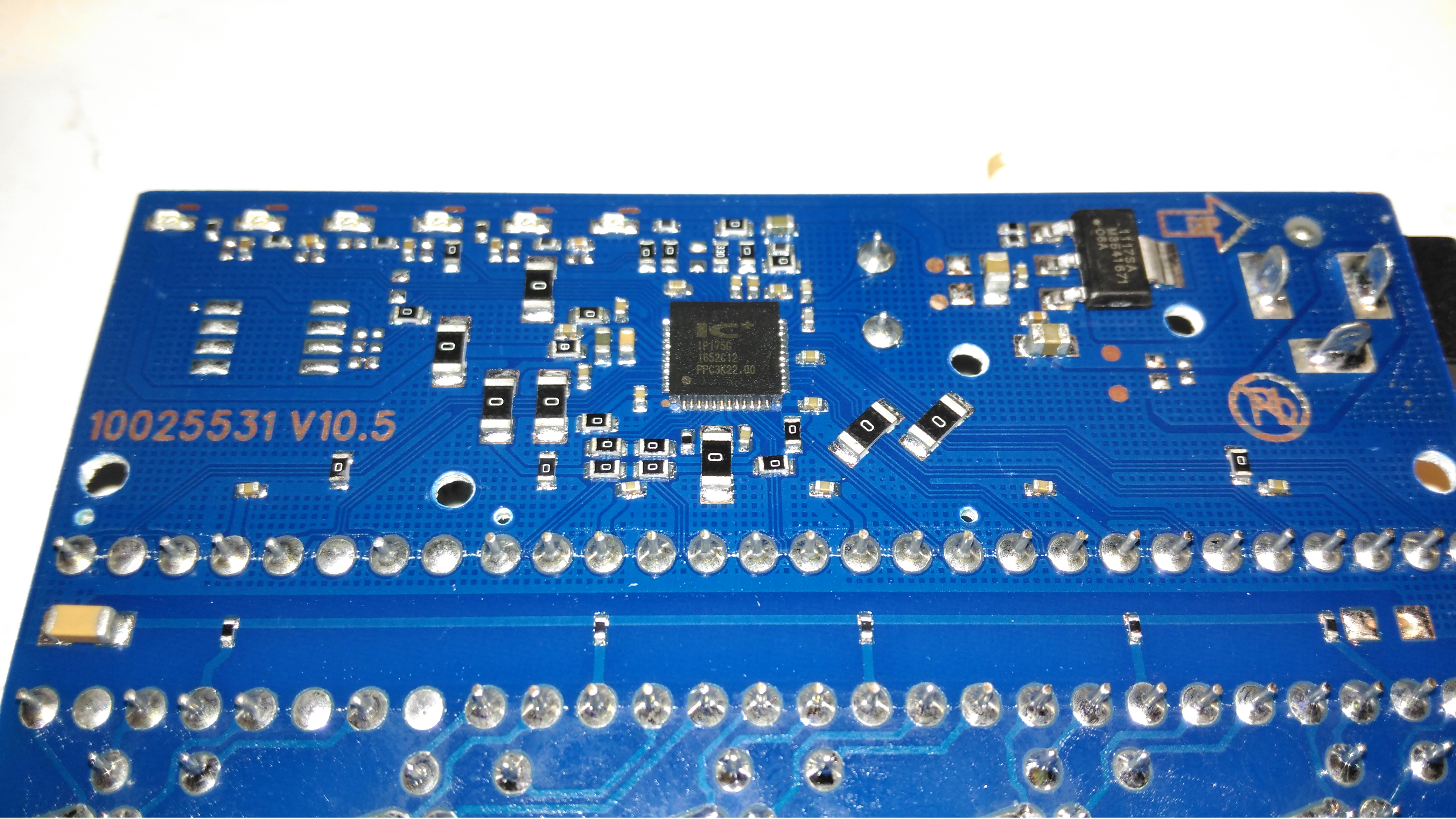
Switch IC
The IC doing all the data switching is an IP175G 5-Port 10/100 Switch from IC+ Corp. No datasheet available for this, but it’s going to be a bog-standard switch.
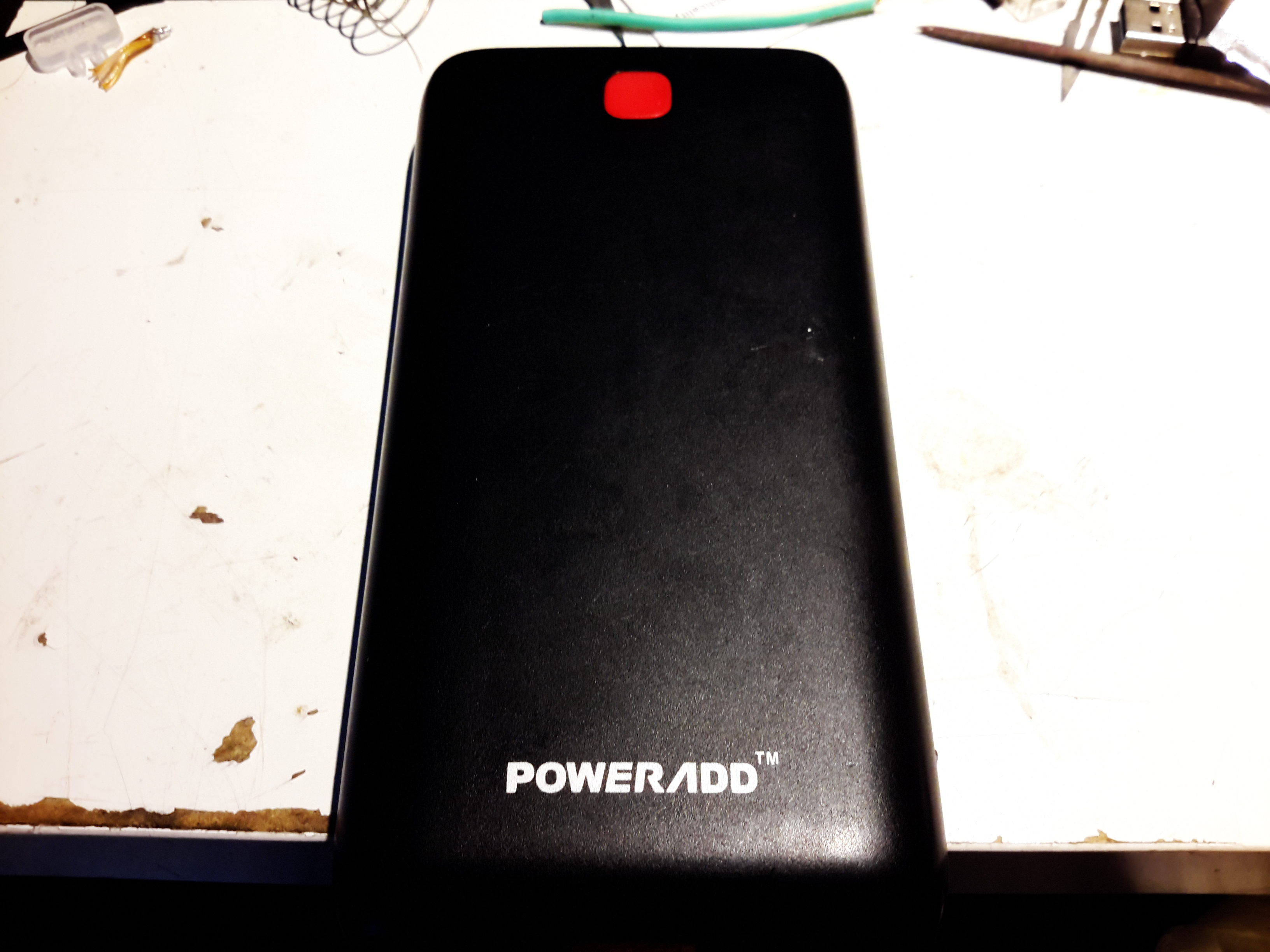
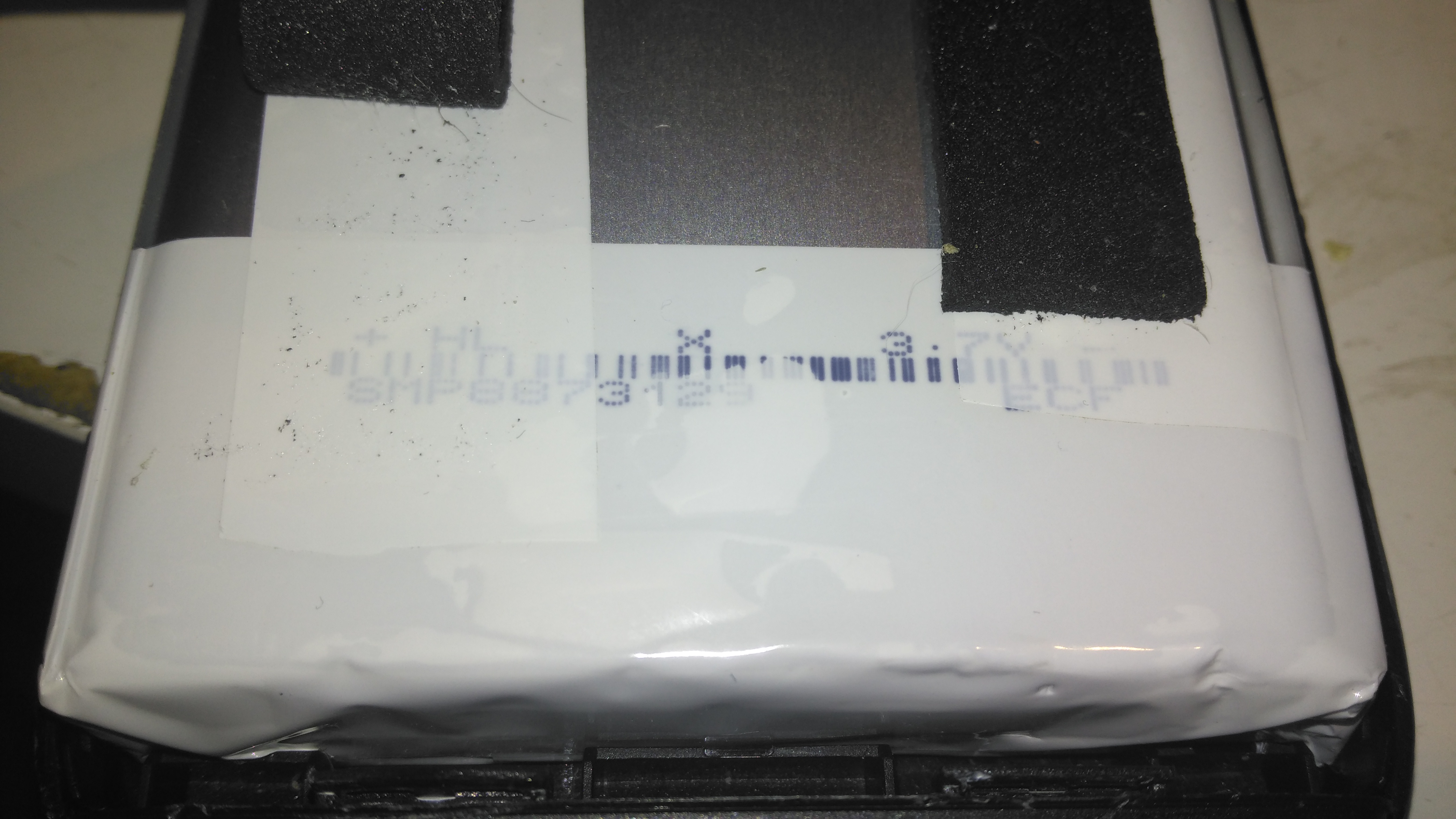
Here’s the biggest portable USB powerbank I’ve seen yet – the PowerAdd Pilot X7, this comes with a 20Ah (20,000mAh) capacity. This pack is pretty heavy, but this isn’t surprising considering the capacity.
USB Ports & LED
The front of the pack houses the usual USB ports, in this case rated at 3.4A total between the ports. There’s a white LED in the centre as a small torch, activated by double-clicking the button. A single click of the button lights up the 4 blue LEDs under the housing that indicate remaining battery capacity. Factory charging is via a standard µUSB connector in the side, at a maximum of 2A.
PCB Front
The front of the PCB holds the USB ports, along with most of the main control circuitry. At top left is a string of FS8025A dual-MOSFETs all in parallel for a current carrying capacity of 15A total, to the right of these is the ubiquitous DW01 Lithium-Ion protection IC. These 4 components make up the battery protection – stopping both an overcharge & overdischarge. The larger IC below is an EG1501 multi-purpose power controller.
This chip is doing all of the heavy lifting in this power pack, dealing with all the DC-DC conversion for the USB ports, charge control of the battery pack, controlling the battery level indicator LEDs & controlling the torch LED in the centre.
EG1501 Example
The datasheet is in Chinese, but it does have an example application circuit, which is very similar to the circuitry used in this powerbank. A toroidal inductor is nestled next to the right-hand USB port for the DC-DC converter, and the remaining IC next to it is a CW3004 Dual-Channel USB Charging Controller, which automatically sets the data pins on the USB ports to the correct levels to ensure high-current charging of the devices plugged in. This IC replaces the resistors R3-R6 in the schematic above.
The DC-DC converter section of the power chain is designed with high efficiency in mind, not using any diodes, but synchronous rectification instead.
PCB Back
The back of the PCB just has a few discrete transistors, the user interface button, and a small SO8 IC with no markings at all. I’m going to assume this is a generic microcontroller, (U2 in the schematic) & is just there to interface the user button to the power controller via I²C.
Cells
Not many markings on the cells indicating their capacity, but a full discharge test at 4A gave me a resulting capacity of 21Ah – slightly above the nameplate rating. There are two cells in here in parallel, ~10Ah capacity each.
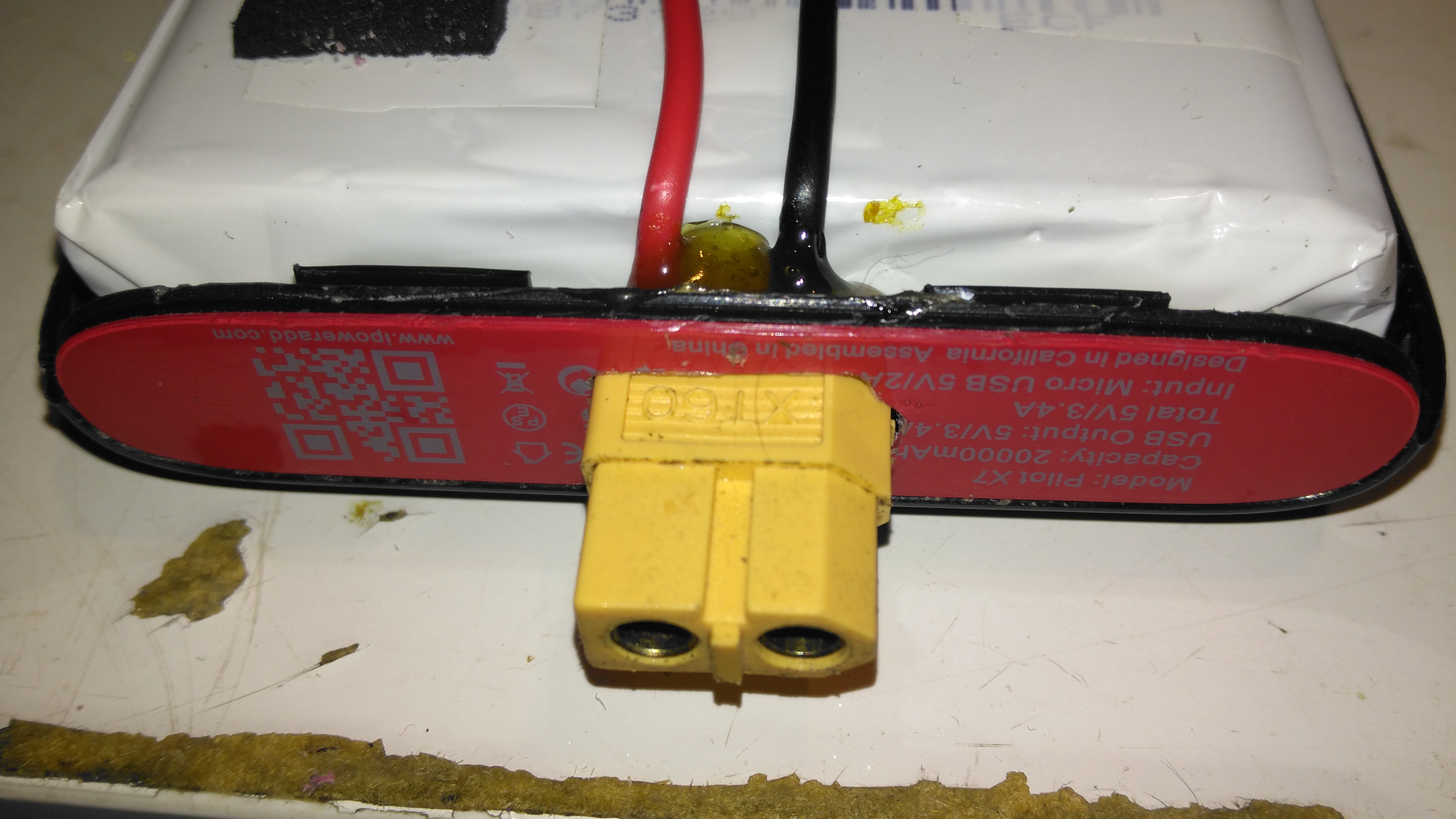
XT60 Battery Connector
The only issue with powerbanks this large is the amount of time they require to recharge themselves – at this unit’s maximum of 2A through the µUSB port, it’s about 22 hours! Here I’ve fitted an XT60 connector, to interface to my Turnigy Accucell 6 charger, increasing the charging current capacity to 6A, and reducing the full-charge time to 7 hours. This splits to 3A charge per cell, and after some testing the cells don’t seem to mind this higher charging current.
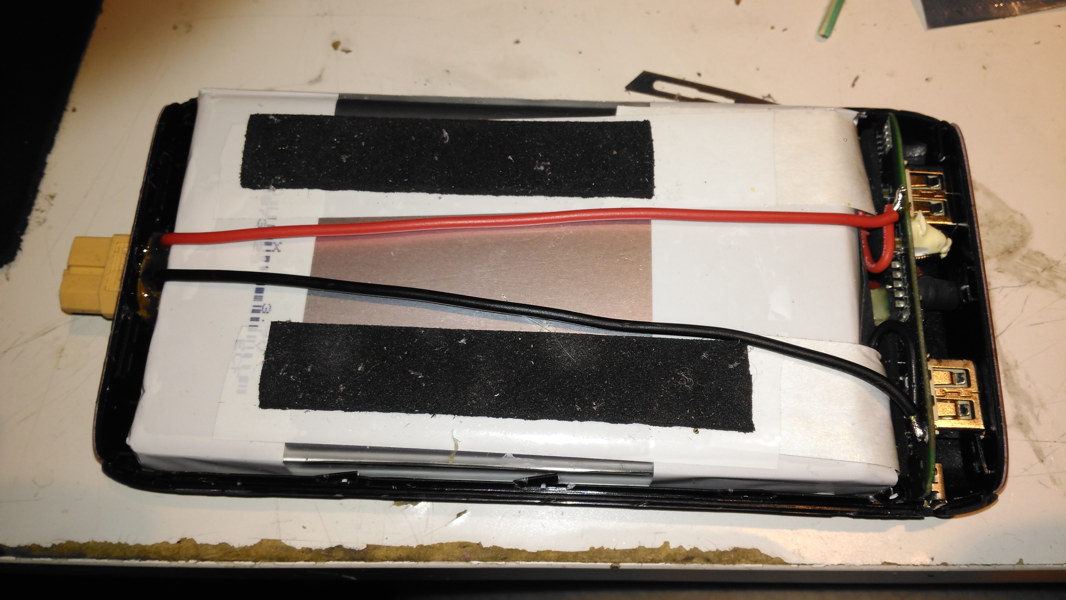
Battery Connector Wiring
The new charging connector is directly connected to the battery at the control PCB, there’s just enough room to get a pair of wires down the casing over the cells.
It’s been a bit quiet around here for a couple of weeks, as it’s the run-up to Download Festival here in the UK, so I’ve been busy sorting everything out for that. Just in time a new order has come in!
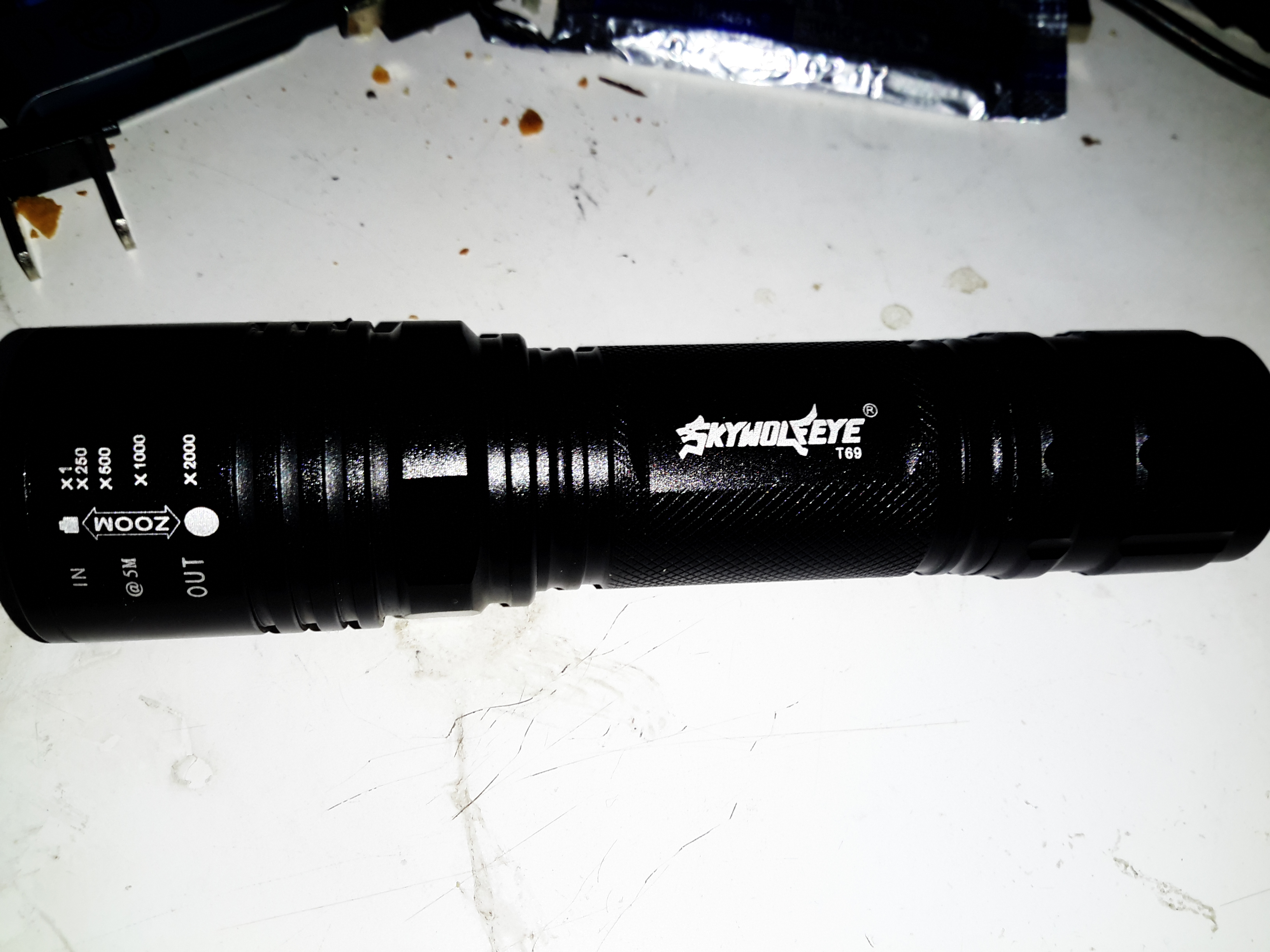
Due to a small accident with the old Maplin torch from a while back, (turns out they don’t float when dropped in the canal – ooops), a new one was sourced. Maplin is very expensive considering the imported crap they peddle these days, so I figured eBay would be the best bet for cheap imported crap 😉 This unit came with a few accessories, so I’ll start with the torch itself.
18650 Torch
This is an aluminium unit, and does feel quite well built for the price, but it does have a few disappointing things. The lens assembly at the front is movable so focus the beam – the range goes from wide flood to a very small spot.
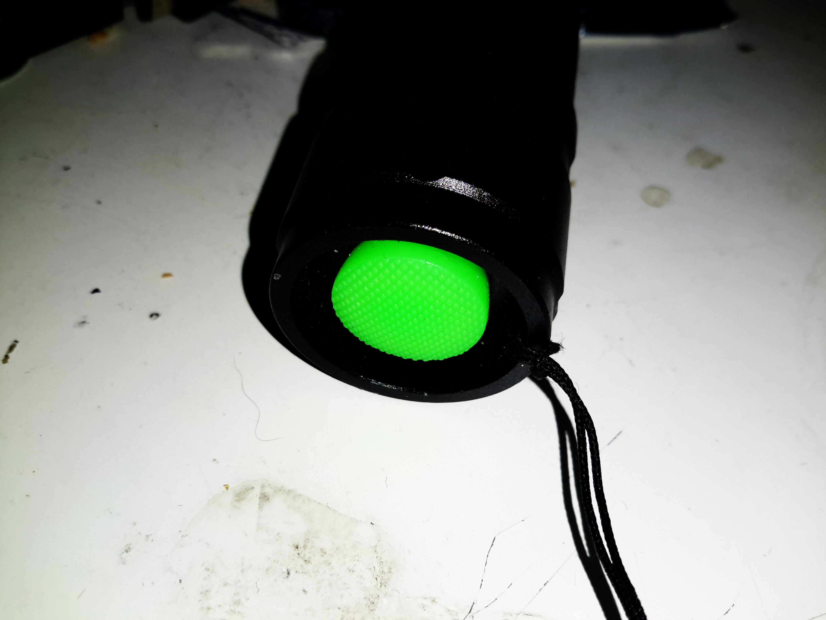
Power Switch
The power switch on this torch is at the back on the cap, covered by this obscenely brightly coloured cap.
Lens Assembly
The lens is a simple plastic moulding, but it produces a nice wide beam.
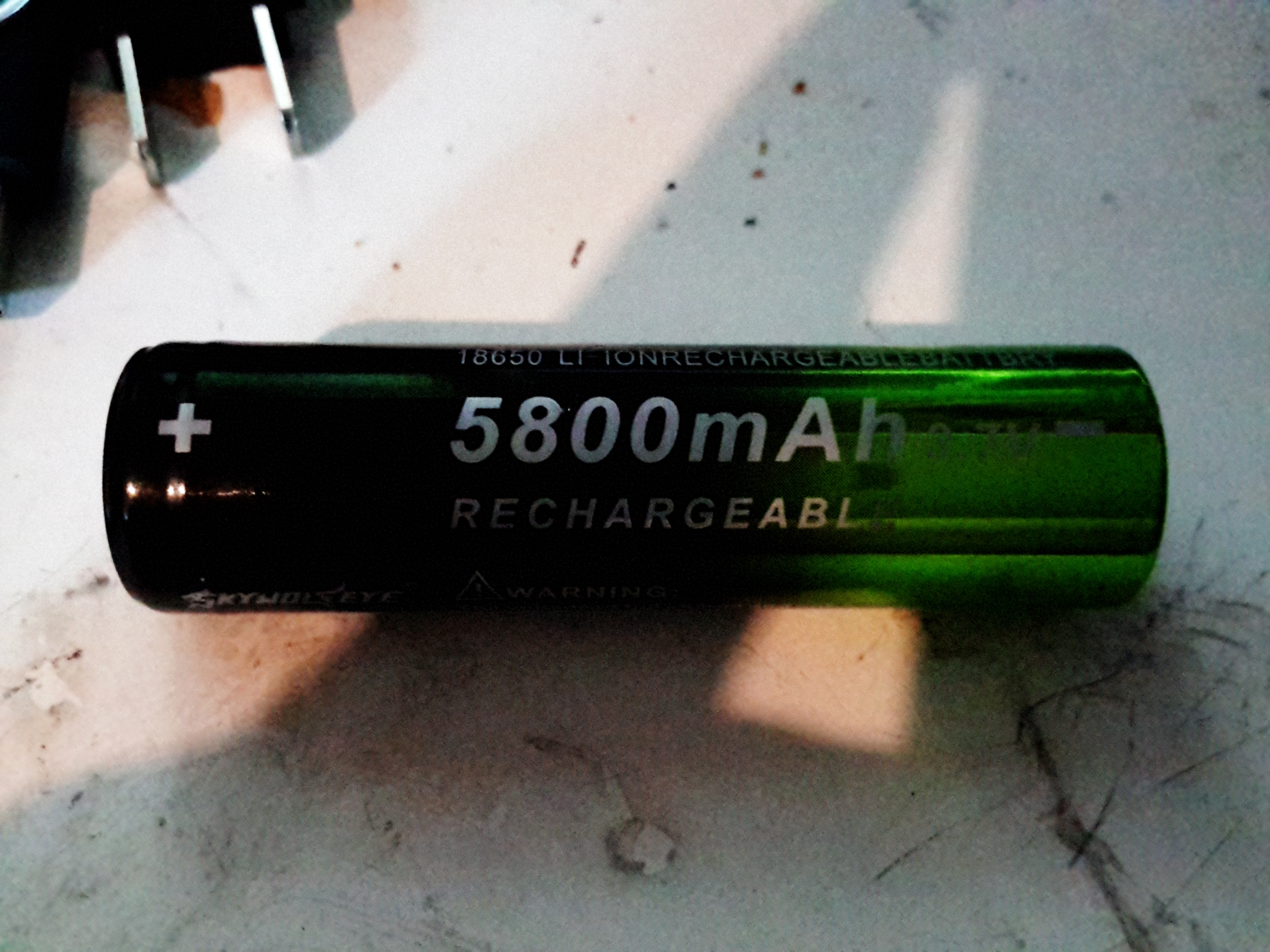
Enthusiastic Numbers
On to the battery supplied – this claims to be a 5.8Ah 18650 cell, which as far as I’m aware do not exist. I’m always dubious of lithium-ion cells from eBay, the Chinese seem to be well into a race to put the biggest numbers that will fit on the label. (I’ve even seen a USB powerbank claming to have 100Ah of capacity!). The largest capacity cells I have at present are LG HG2 18650s, and those are only rated at 3Ah a piece. They’re also relatively expensive.
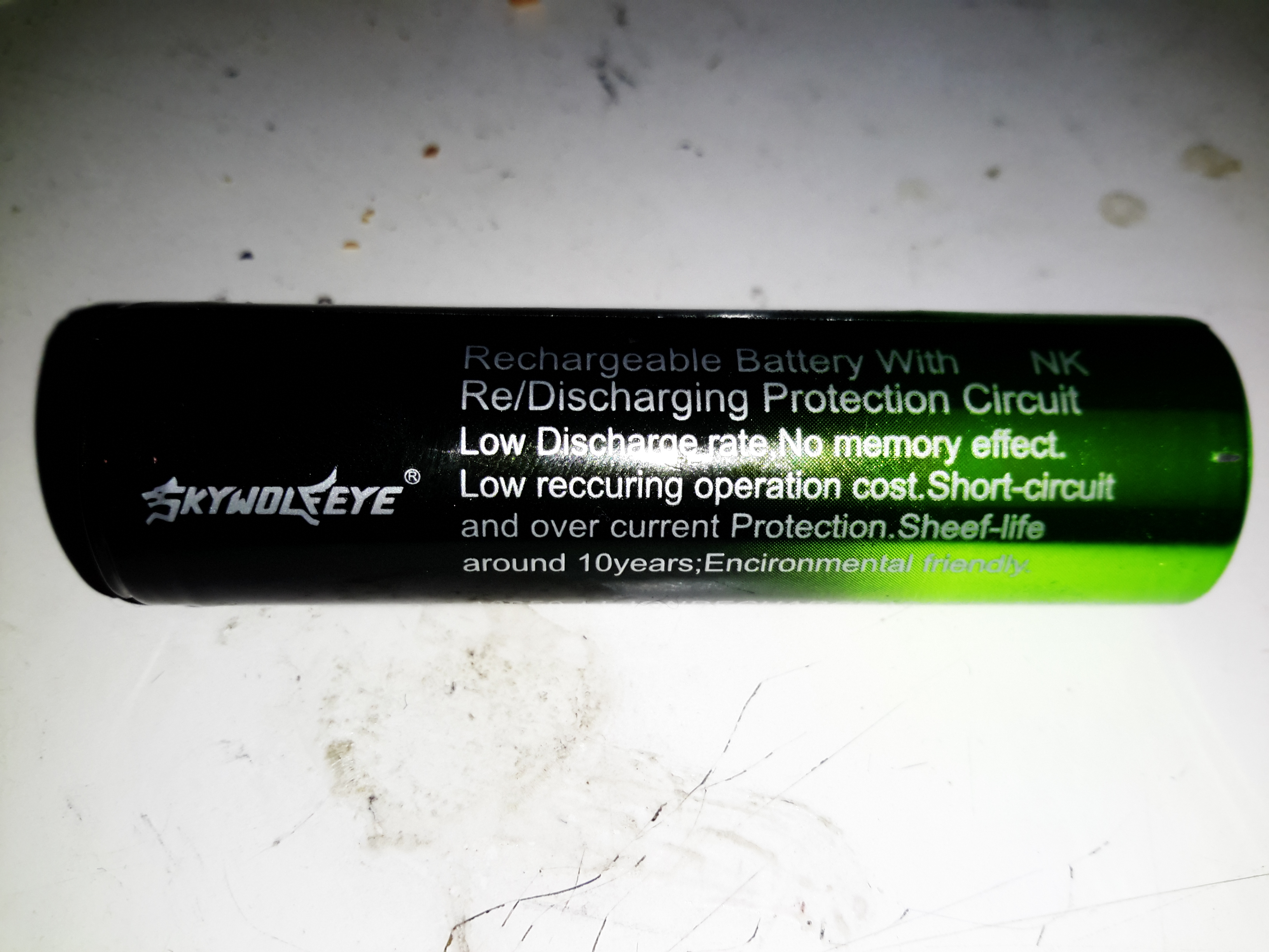
Label
The manufacturer couldn’t even get the label spelling correct! Although they do apparently have a 10 year “sheef” life. Never seen that from an 18650 either. They tend to discharge on their own if left unused in about 12 months. I wouldn’t like to think of what the self-discharge rate of these dodgy things is, and I don’t intend to keep them to find out either!
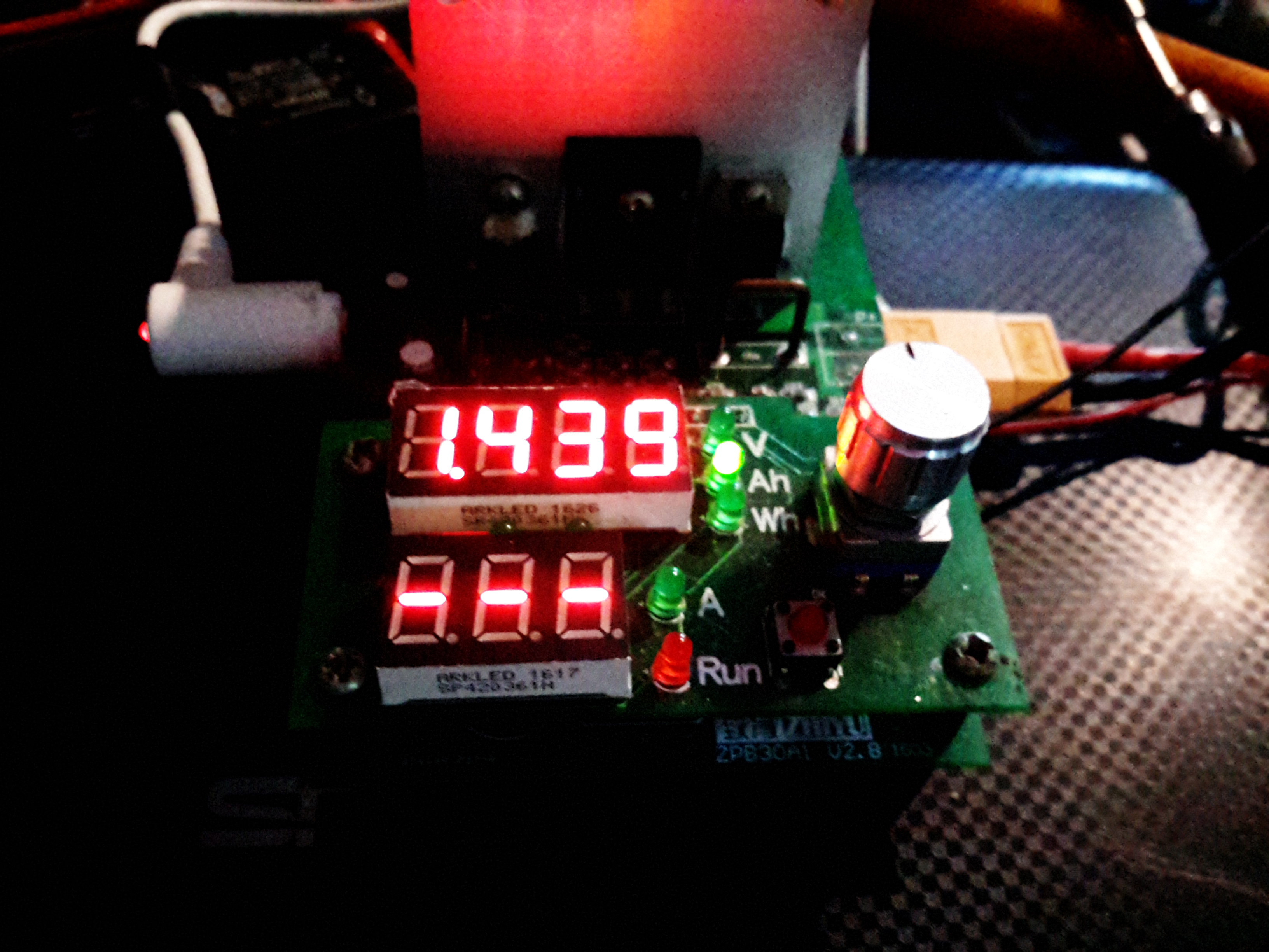
Battery Capacity
After a quick blast on the charger to top them up, on the discharge tester they go! This test was conducted at 1A, and this now shows the true capacity of 1.439Ah, which is honestly better than I was expecting. Already having high quality cells I wasn’t fussed about this aspect of the purchase, I knew these cells would end up in the bin.
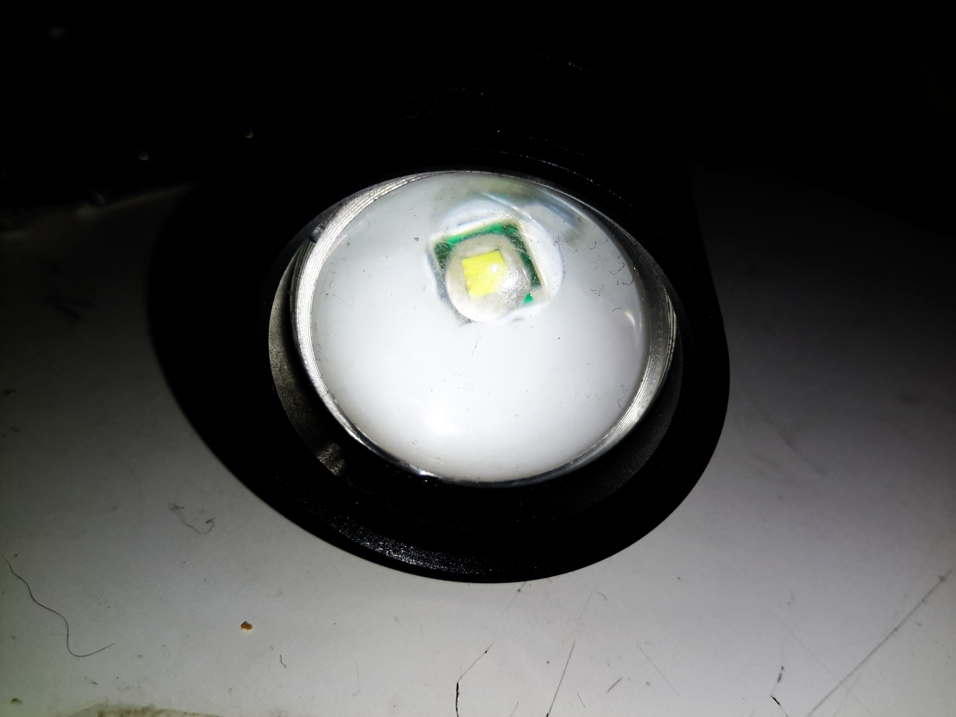
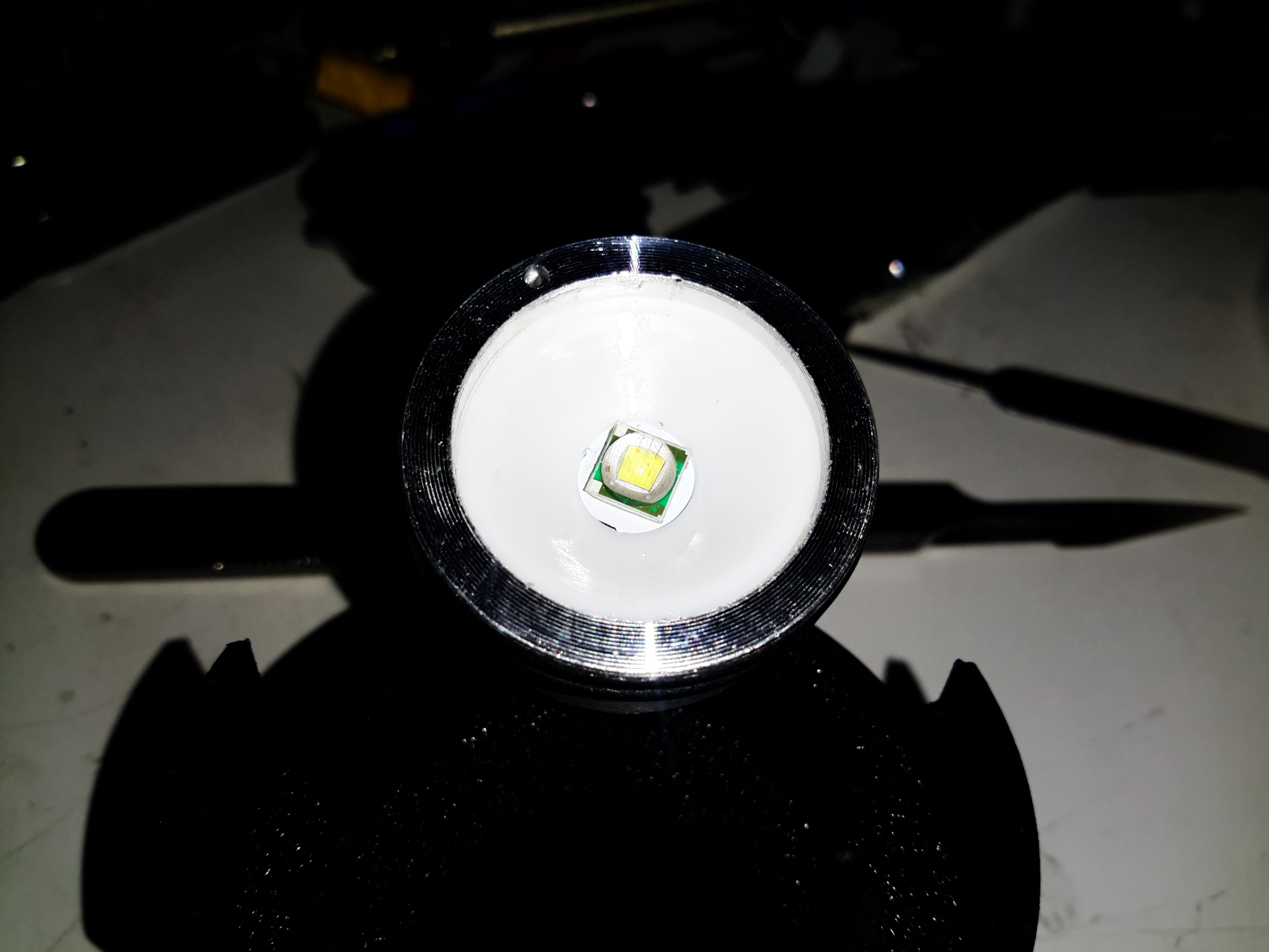
LED Module
Unscrewing the lens housing at the front gives access to the LED module – this is a Cree XM-L die in here, although it might not be a genuine Cree (or possibly a factory reject). The LED housing is aluminium, the LED uses this as a heatsink.
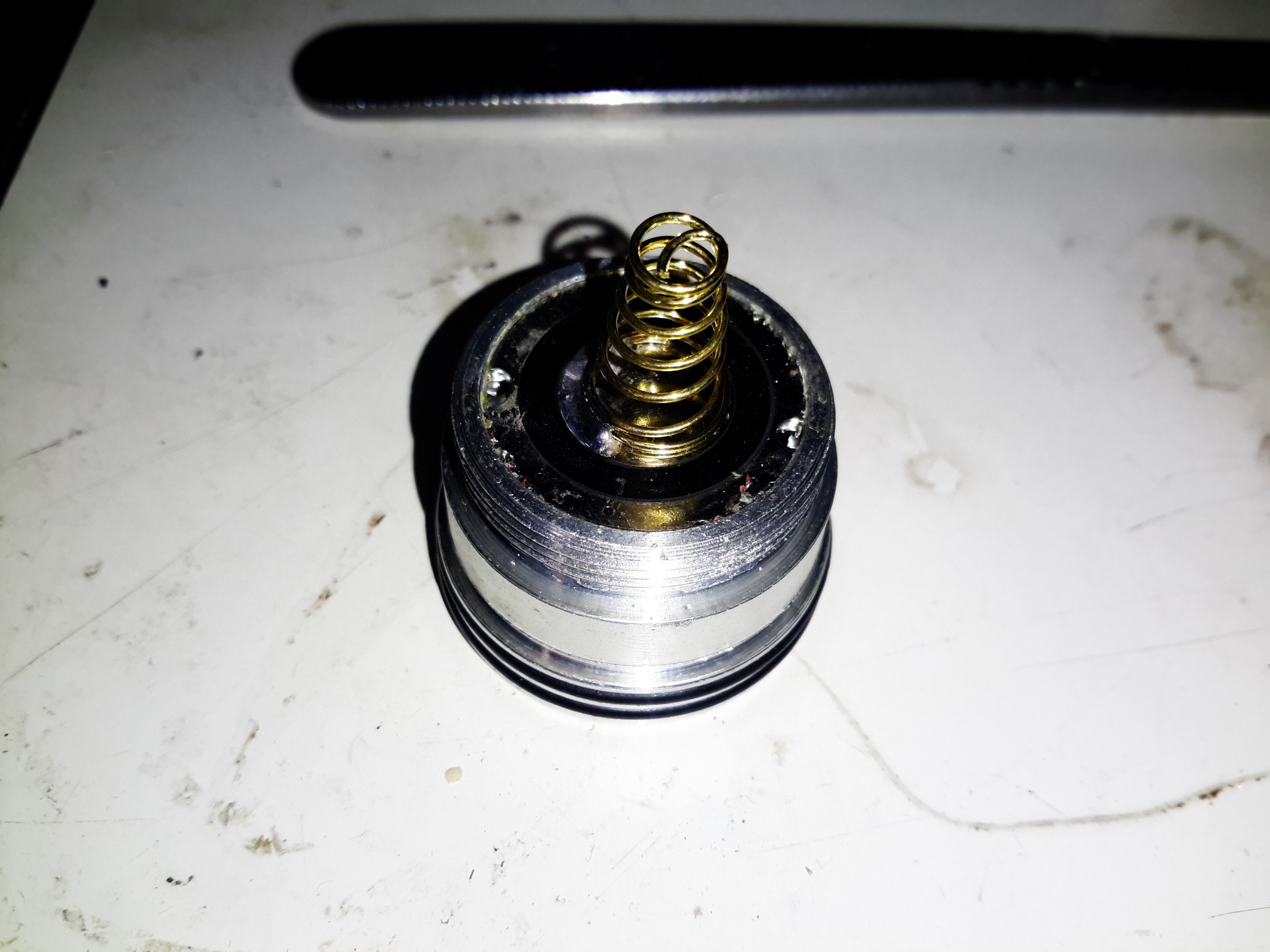
Positive Contact Spring
Nothing special about the back of the module after it’s been unscrewed from the barrel. There’s a couple of O-Rings to seal the sliding lens assembly, I lubricated these with some silicone grease to try & make the housing somewhat splashproof.
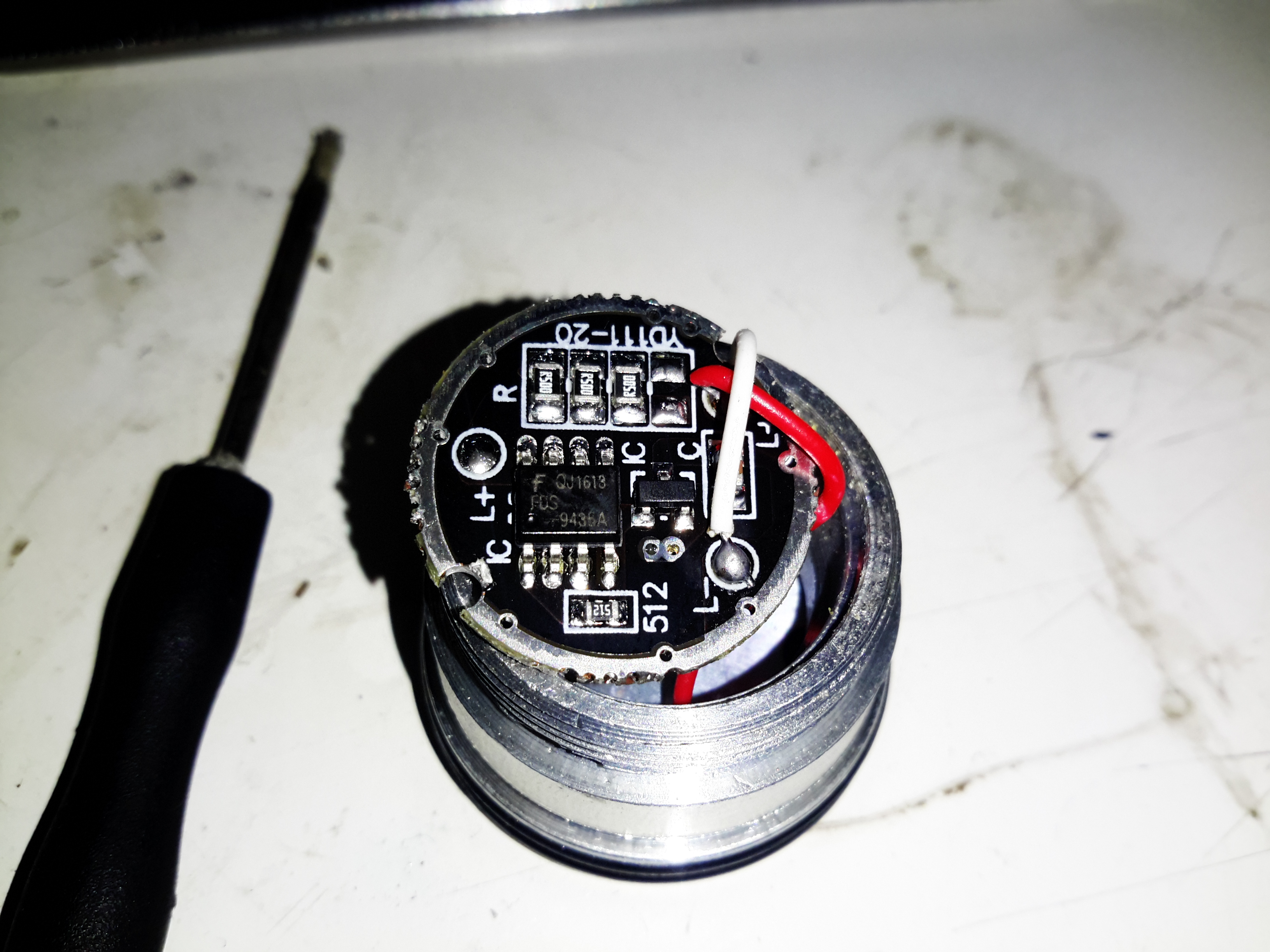
Control PCB
The control PCB is pulled out of the housing to reveal the circuitry. The LED is controlled by a SOT-23 mode IC & a SO-8 MOSFET. There’s nothing complex about the LED current limiting, just a bunch of SMD resistors in parallel to set the limit. This torch, like 99% of Chinese import torches from eBay, has a multi-mode IC with SOS & strobe. I don’t need this crap, and it’s easily bypassed.
Modifications
Here I’ve desoldered the MOSFET from the board & jumped across it’s drain & source connections, converting the torch to simple ON/OFF control.
Tip Jar
If you’ve found my content useful, please consider leaving a donation by clicking the Tip Jar below!
All collected funds go towards new content & the costs of keeping the server online.