Posted on Leave a comment

Another Chinese Charger

I almost forgot about this bit of kit, that came with one of my LED torches as a Lithium Ion charger. As I never plug in anything that comes from China via eBay, here’s the teardown & analysis.

Another Lethal Charger?

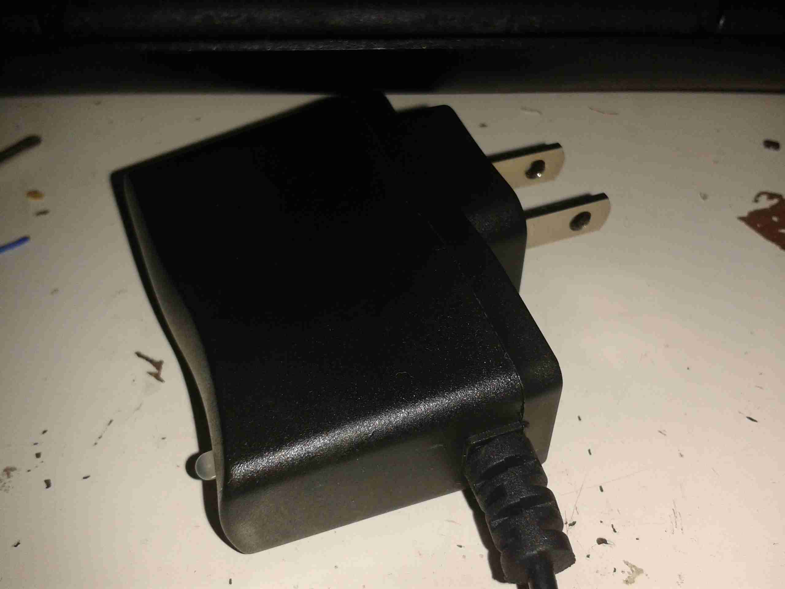
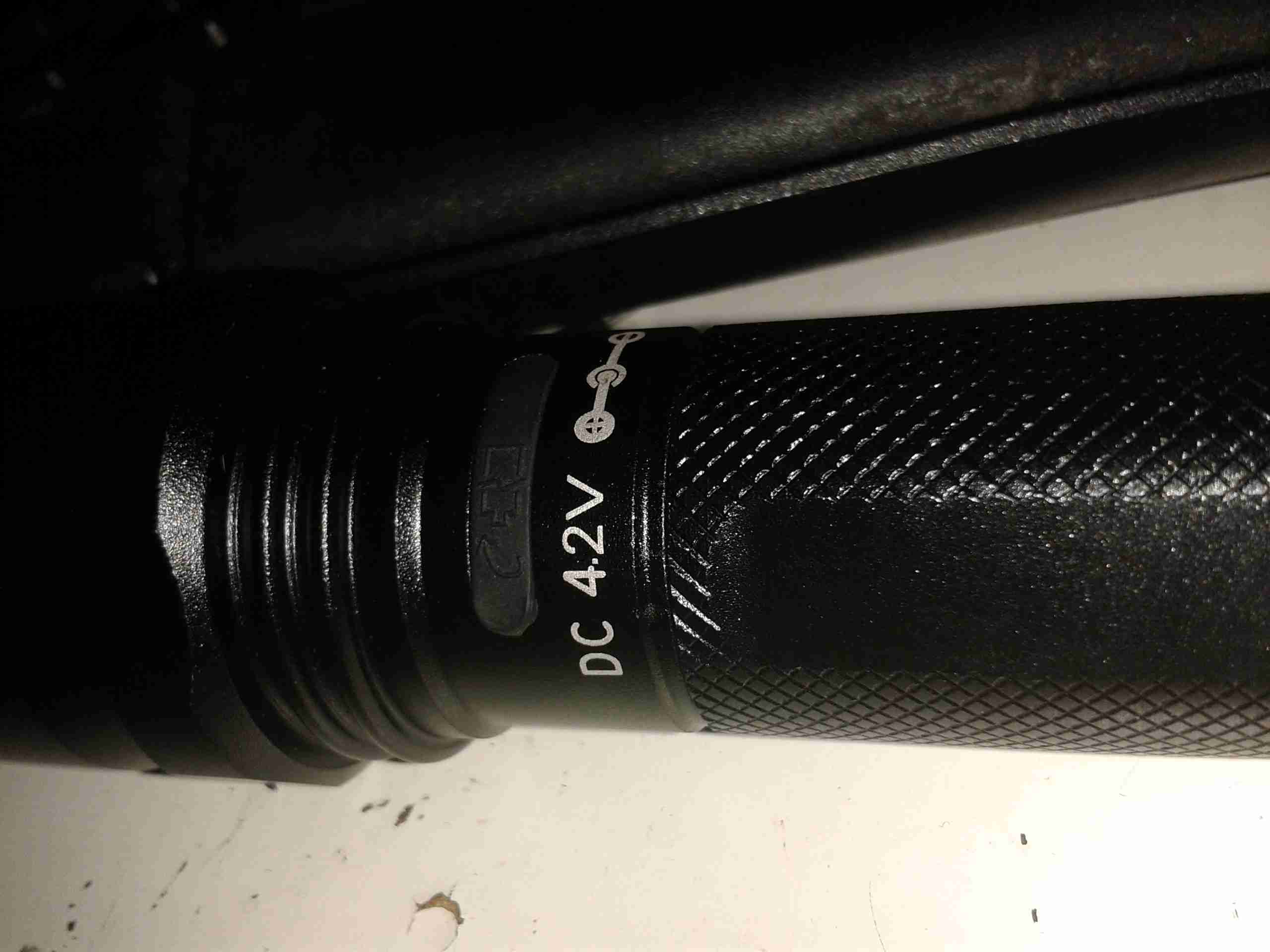
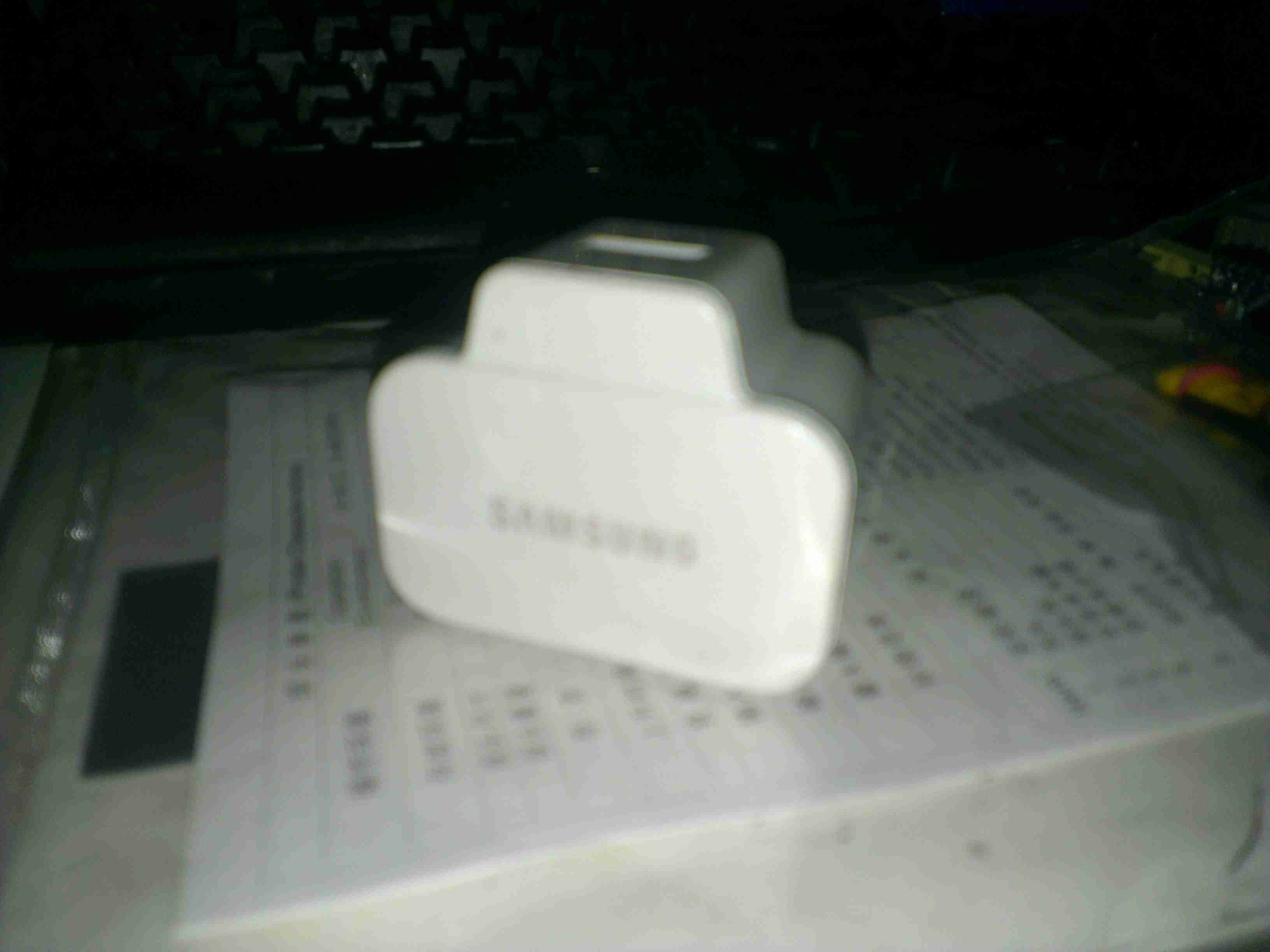
Here’s the unit itself. It’s very light, and is clearly intended for American NEMA power points.

Specs
Specs

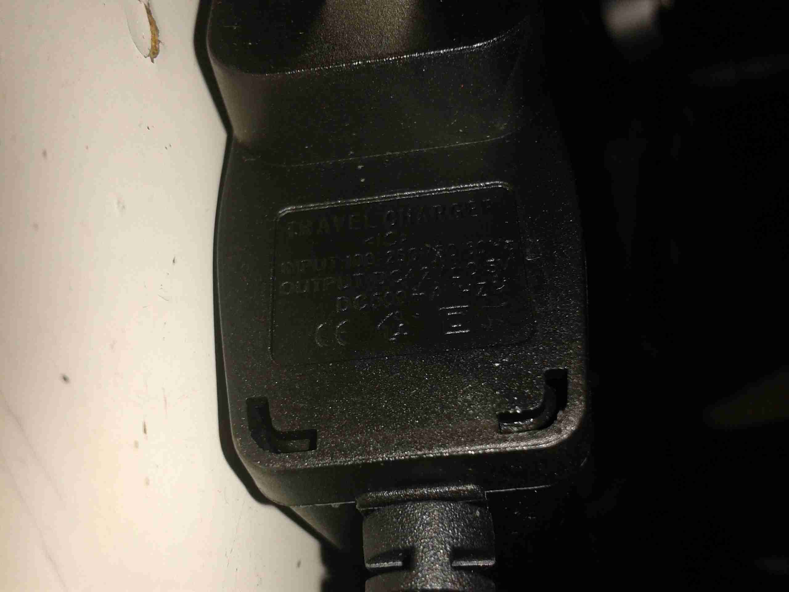
Claimed specifications are 100-240v AC input, making it universal, and 4.2v DC out ±0.5v at 500mA.
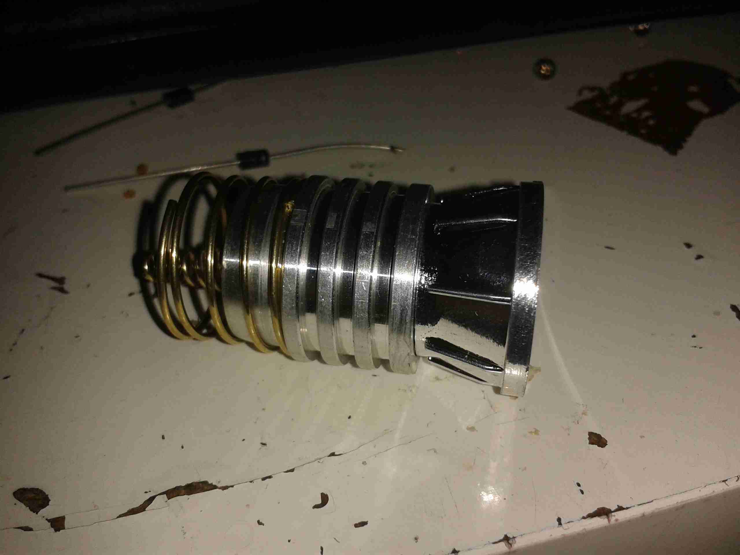
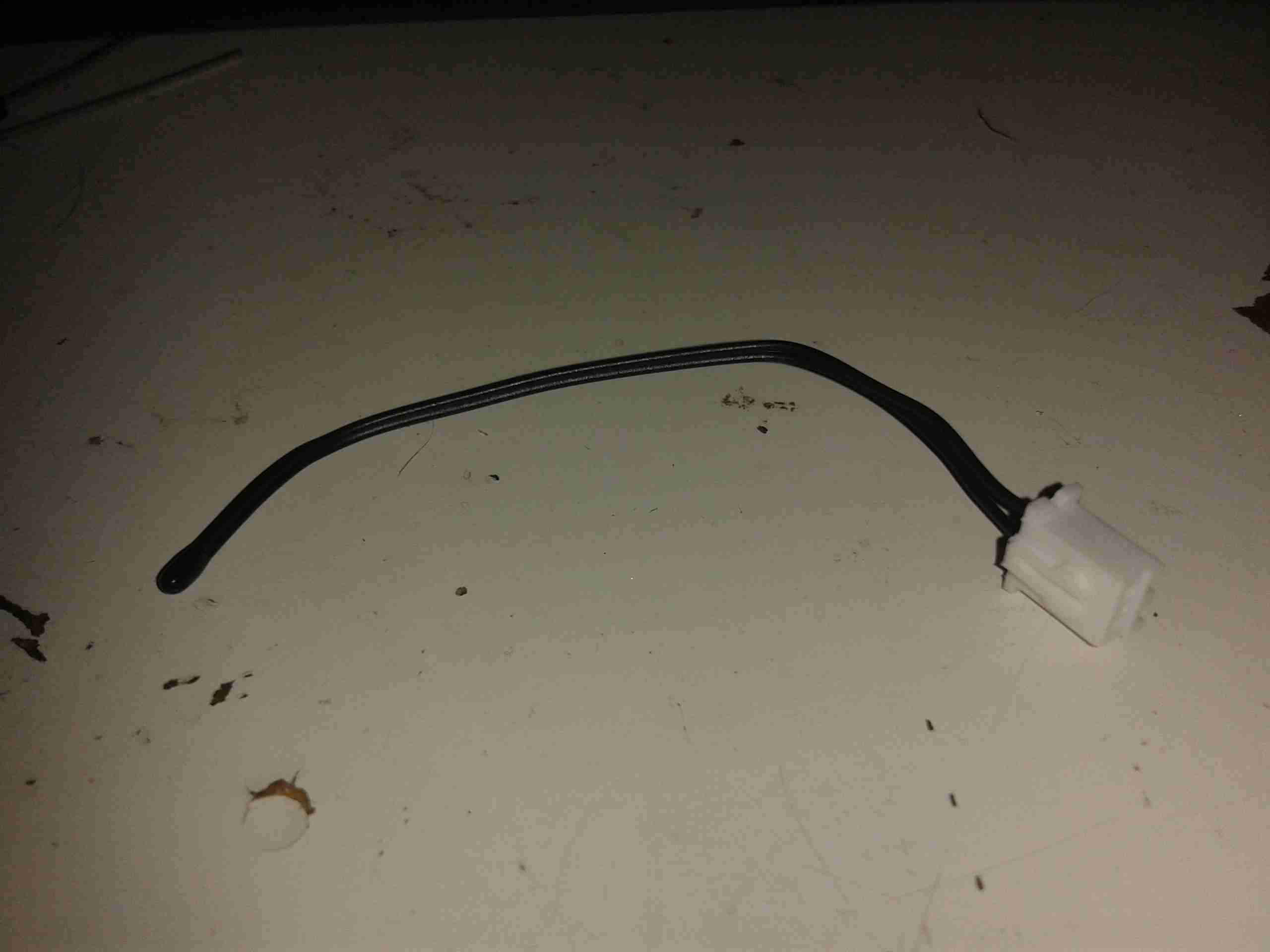
Considering the size of the output wire, if this can actually output rated voltage at rated current I’ll be surprised.

Opened
Opened

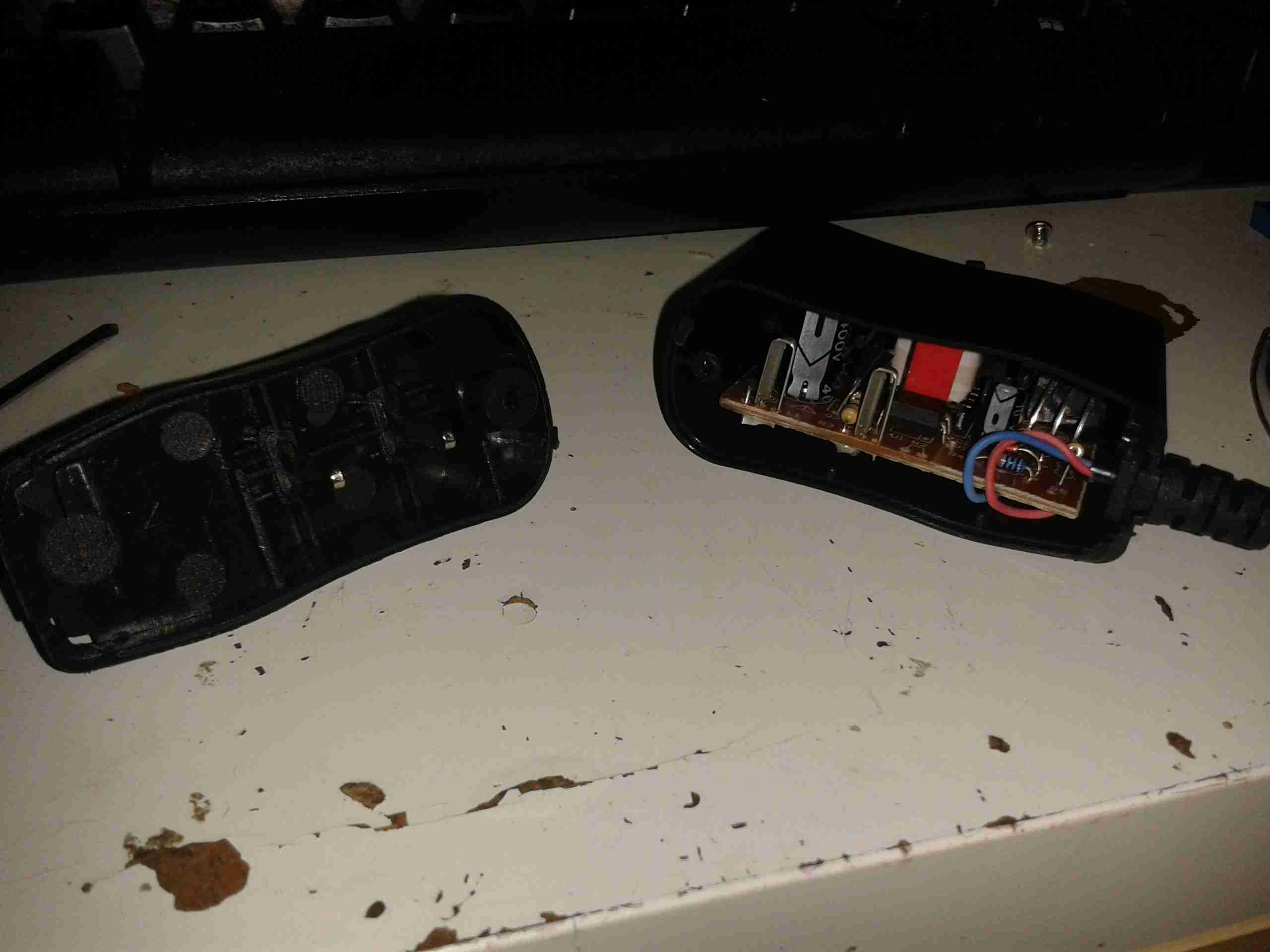
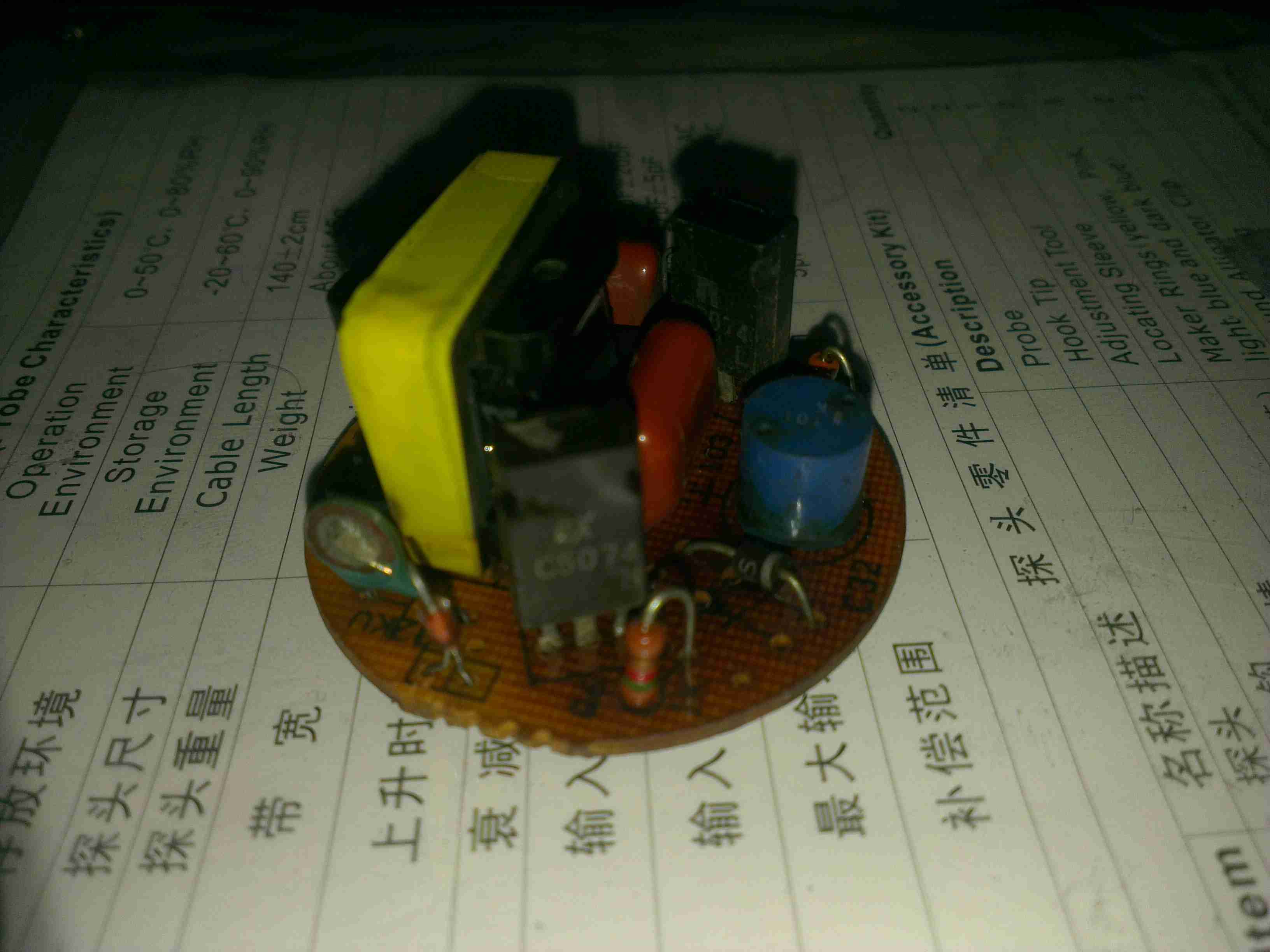
Here’s the adaptor opened up. There’s no mains wiring to speak of, the mains pins simply push into tags on the PCB.

PCB Top
PCB Top

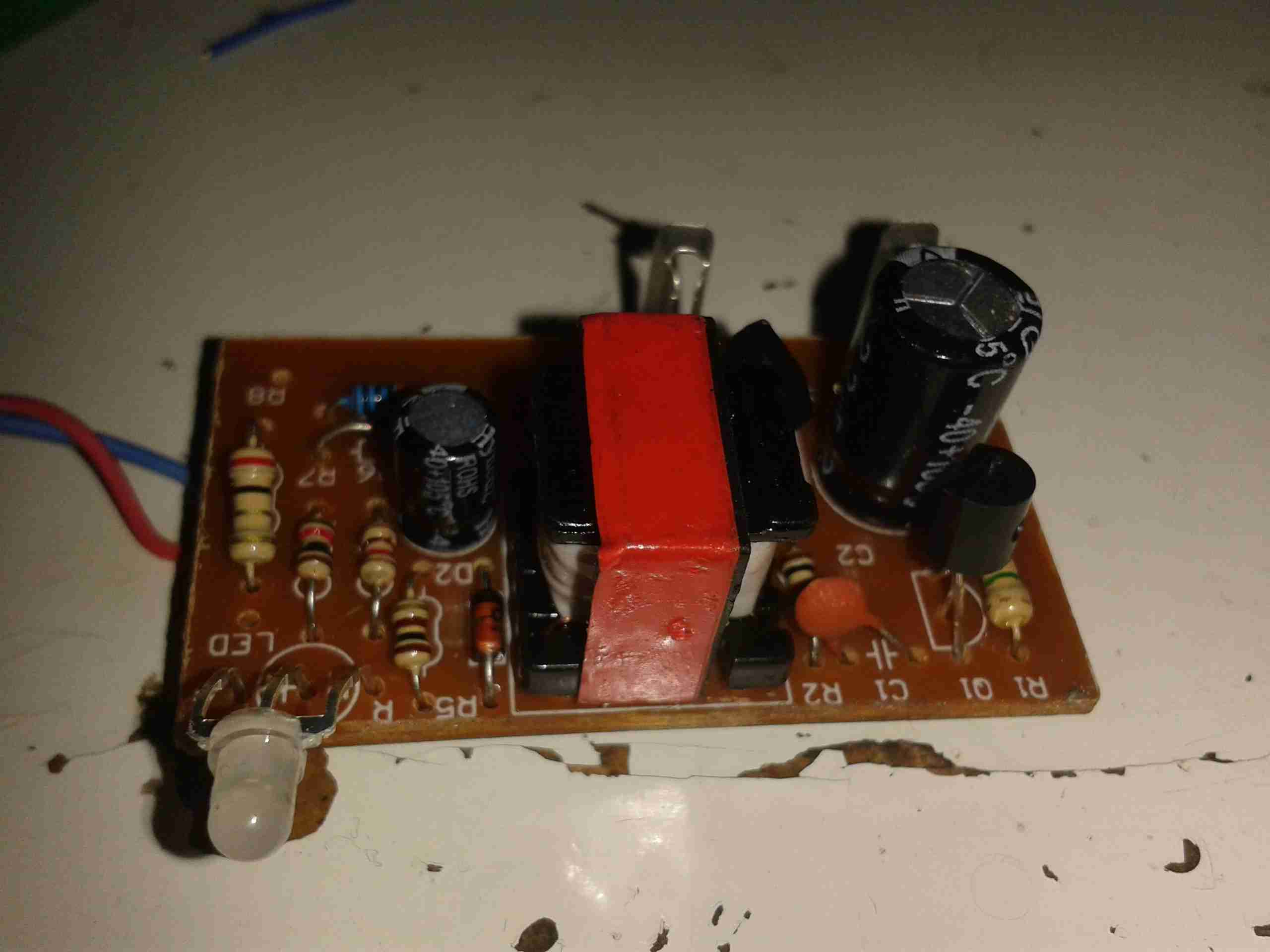
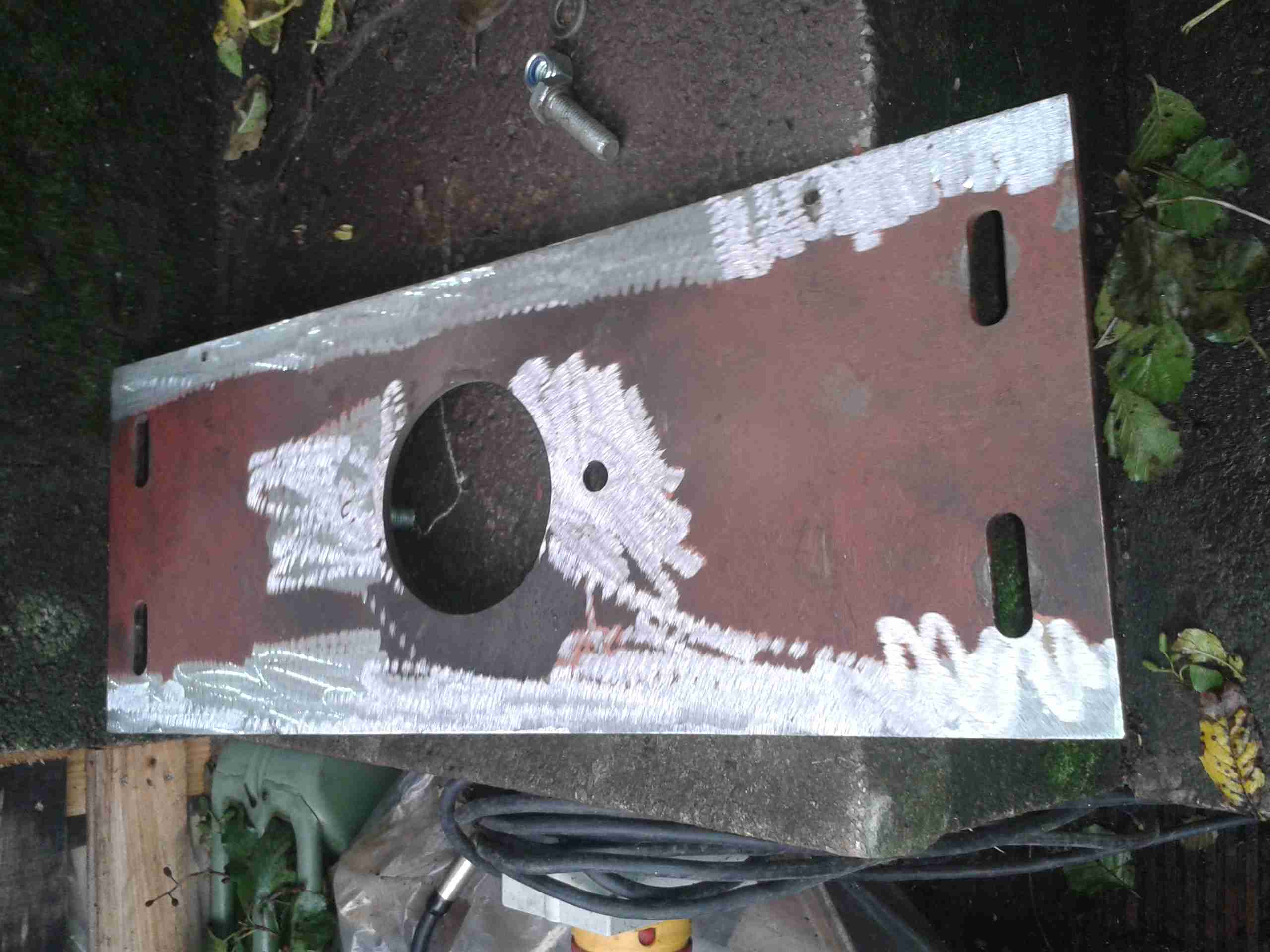
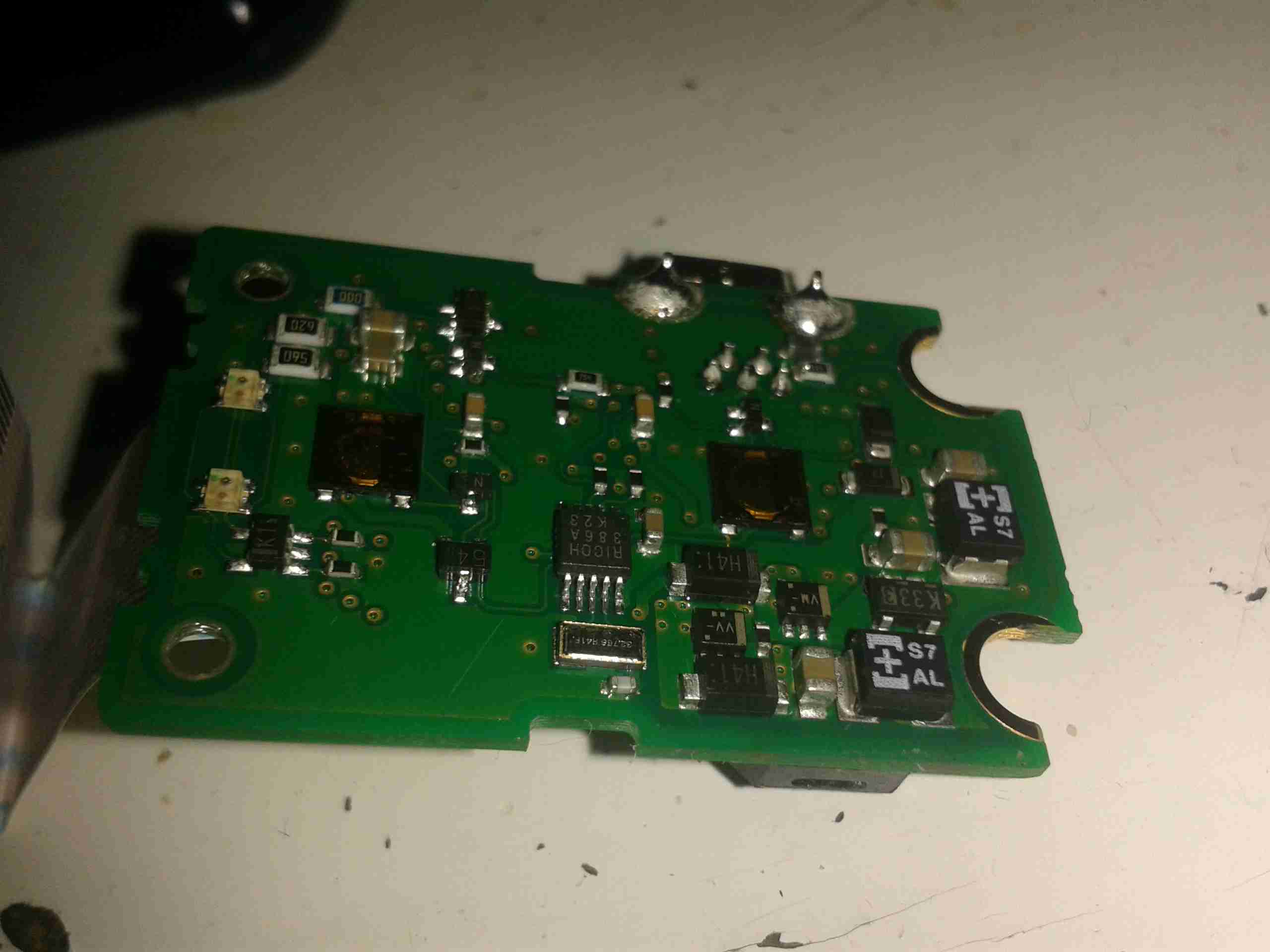
Top of the SMPS PCB. As usual with Chinese gear, it’s very simple, very cheap and likely very dangerous. There’s no real fusing on the mains input, only half-wave rectification & no EMI filtering.

PCB Bottom
PCB Bottom

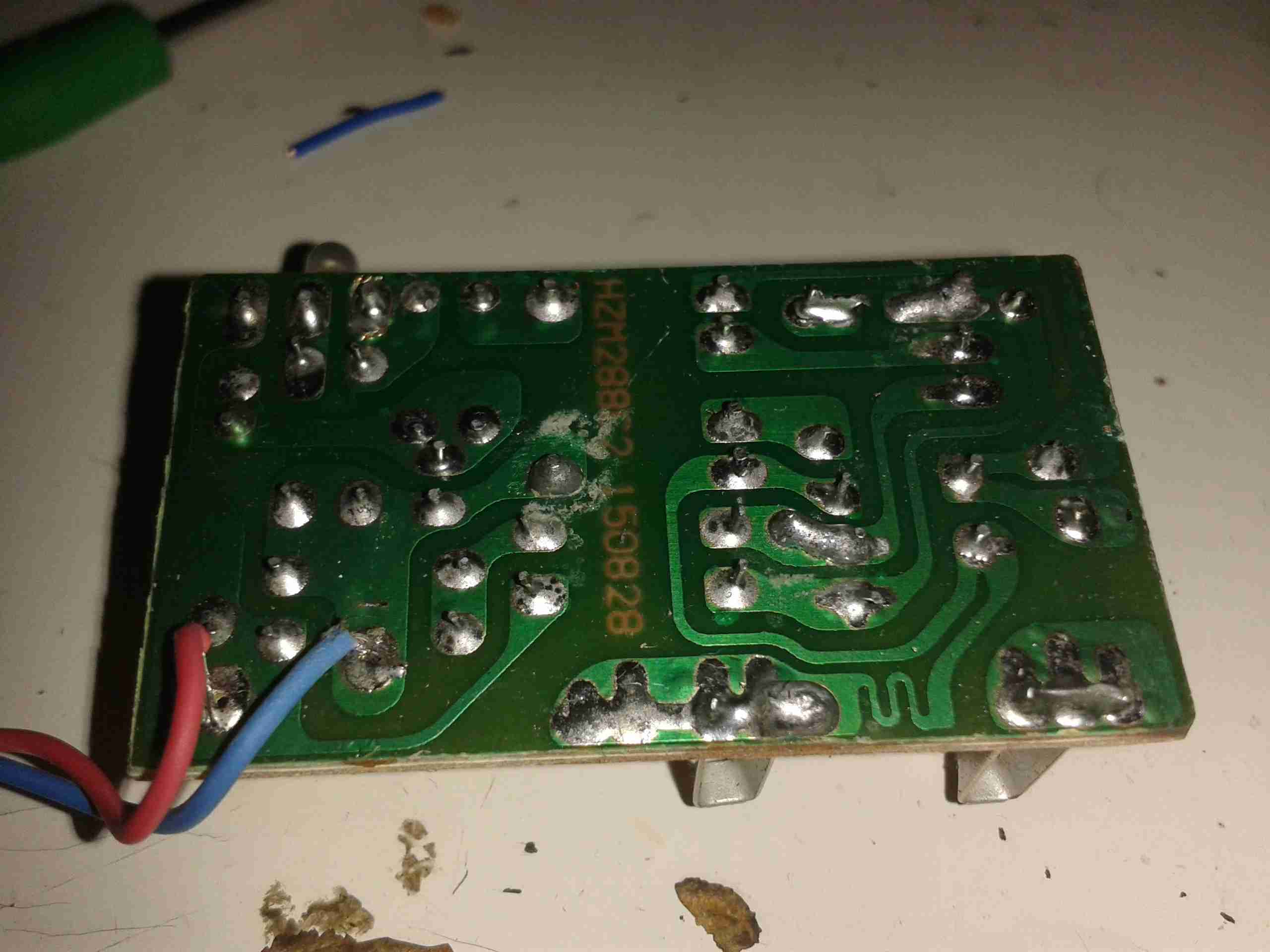
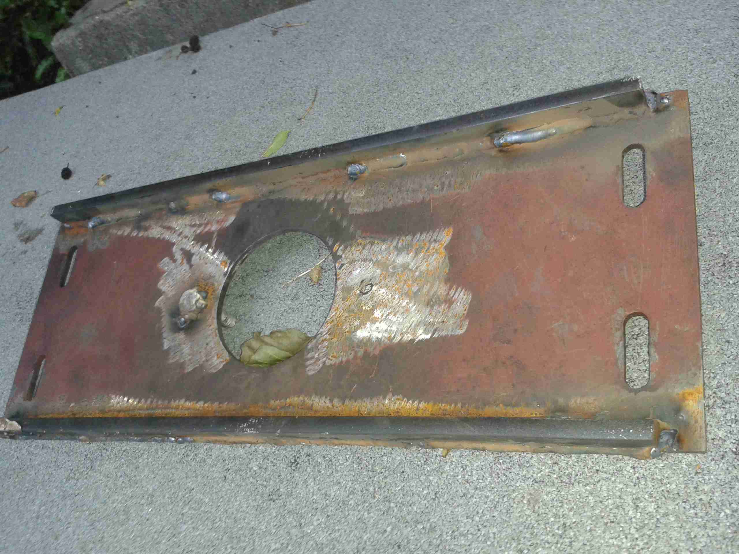
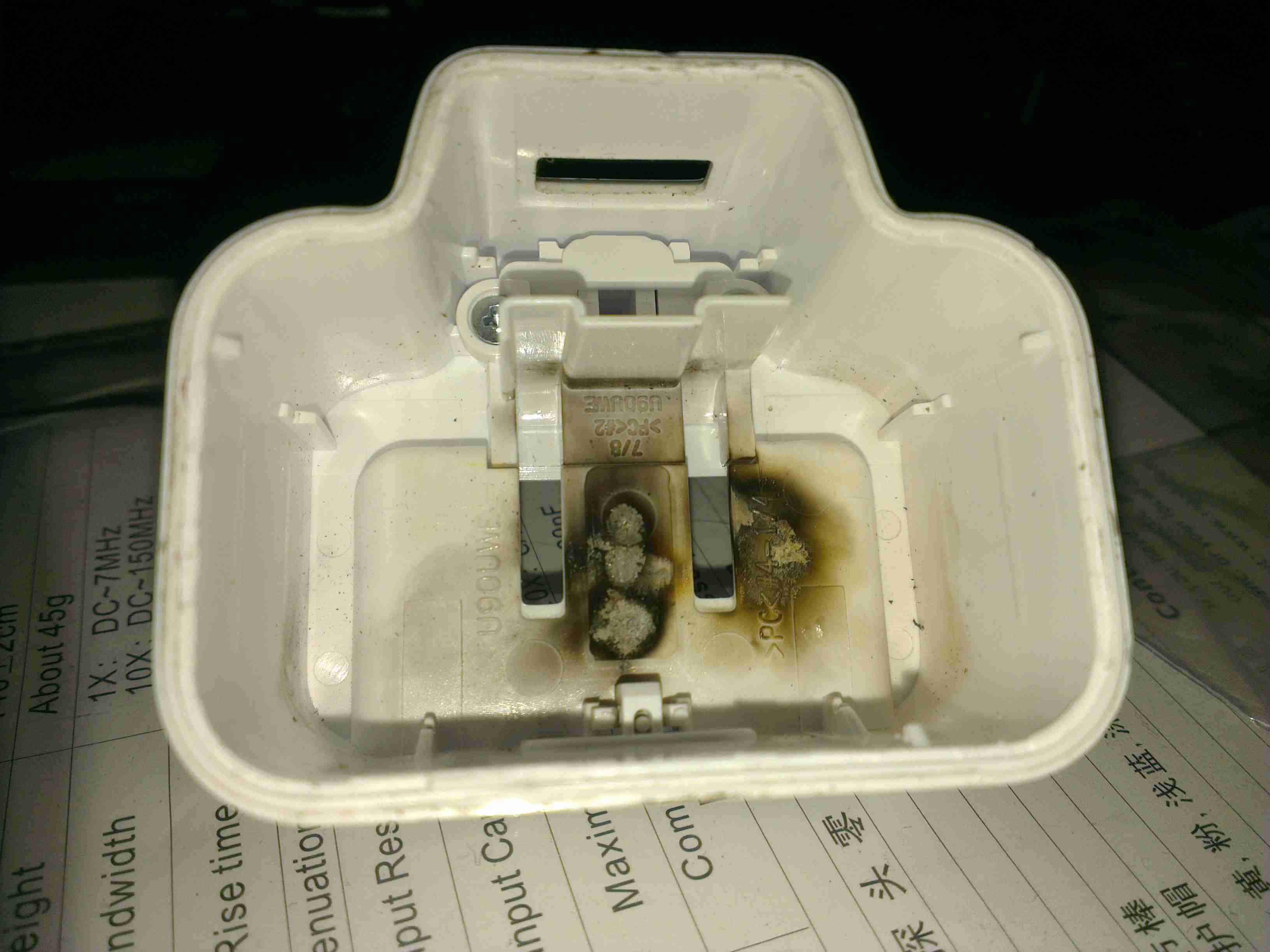
Here’s the bottom of the PCB. At least there’s a fairly sized gap between the mains & the output for isolation. The wiggly bit of track next to one of the mains input tags is supposed to be a fuse – I somehow doubt that it has the required breaking characteristics to actually pass any safety standards. Obviously a proper fuse or fusible resistor was far too expensive for these.

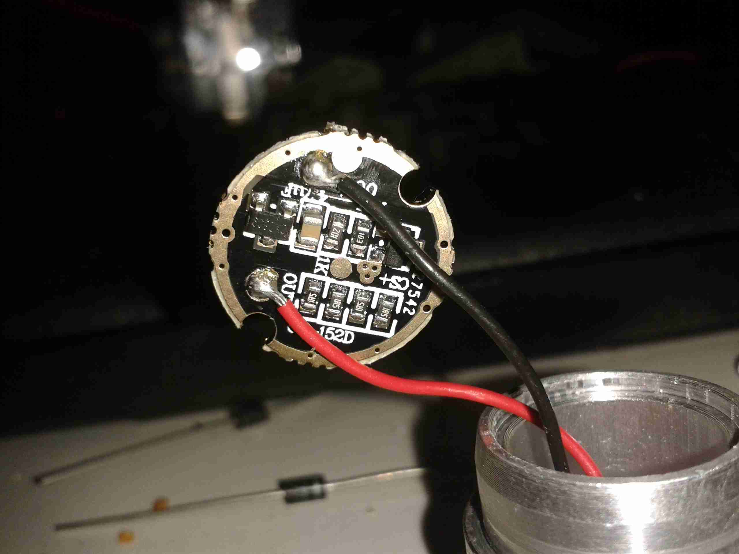
The output wiring on the left is thinner than hair, I’d say at least 28AWG, and probably can’t carry 500mA without suffering extreme volt drop.

Posted on Leave a comment

5-Port HDMI Switch

HDMI Switch
HDMI Switch

Here’s another quick teardown, a cheap 5-port HDMI switch box. This is used to allow a single input on a monitor to be used by 5 different external HDMI devices, without having to mess about plugging things in.

Power & Remote
Power & Remote

Here’s the DC barrel jack & 3.5mm TRS jack for power & remote control. There’s a little IR decoder & remote that go with this for hands free switching.

PCB Top
PCB Top

Here’s the PCB out of it’s plastic housing. The main logic is a pair of PI3HDMI303 3:1 HDMI switches from Pericom Semiconductor. These are cascaded for the 5-ports, the first 3 input HDMI ports are switched through both ICs to reach the output.
These HDMI switch ICs are operated with TTL input pins, the combination of these pins held either high or low determines the input port that appears on the output.
There’s a button on the left for switching between inputs, with a row of 5 LED indicators.

PCB Bottom
PCB Bottom

Not much on the bottom side, a lot of passives & bypass capacitors. There’s a 3.3v LDO regulator on the left for supplying the main rail to the active switch ICs. The IC on the right doesn’t have any numbering at all, but I’m presuming it’s a microcontroller, dealing with the IR remote input & pushbutton inputs to switch the inputs.

Posted on Leave a comment

Maplin/Refrakta Torch Modification & Mode Removal

The multimode dimming/flashing modes on Chinese torches have irritated me for a while. If I buy a torch, it’s to illuminate something I’m doing, not to test if people around me have photosensitive epilepsy.

Looking at the PCB in the LED module of the torch, a couple of components are evident:

LED Driver PCB
LED Driver PCB

There’s not much to this driver, it’s simply resistive for LED protection (the 4 resistors in a row at the bottom of the board).
The components at the top are the multimode circuitry. The SOT-23 IC on the left is a CX2809 LED Driver, with several modes. The SOT-23 on the right is a MOSFET, for switching the actual LED itself. I couldn’t find a datasheet for the IC itself, but I did find a schematic that seems to match up with what’s on the board.

Schematic
Schematic

Here’s that schematic, the only thing that needs to be done to convert the torch to single mode ON/OFF at full brightness, is to bridge out that FET.

Components Desoldered

To help save the extra few mA the IC & associated circuitry will draw from the battery, I have removed all of the components involved in the multimode control. This leaves just the current limiting resistors for the LED itself.

Jumper Link
Jumper Link

The final part above, is to install a small link across the Drain & Source pads of the FET. Now the switch controls the LED directly with no silly electronics in between. A proper torch at last.

Posted on Leave a comment

DIY SMPS Fan Controller

Now the controllers have arrived, I can rejig the supplies to have proper thermal control on their cooling.

Changes Overview
Changes Overview

Here’s the top off the PSU. The board has been added to the back panel, getting it’s 12v supply from the cable that originally fed the fan directly. Luckily there was just enough length on the temperature probe to fit it to the output rectifier heatsink without modification.

To connect to the standard 4-pin headers on the controller, I’ve spliced on a PC fan extension cable, as these fans spent their previous lives in servers, with odd custom connectors.

Fan Controller
Fan Controller

Here’s the controller itself, the temperature probe is inserted between the main transformer & the rectifier heatsink.
I’ve set the controller to start accelerating the fan at 50°C, with full speed at 70°C.

Full Load Test
Full Load Test

Under a full load test for 1 hour, the fan didn’t even speed up past about 40% of full power. The very high airflow from these fans is doing an excellent job of keeping the supply cool. Previously the entire case was very hot to the touch, now everything is cool & just a hint of warm air exits the vents. As the fan never runs at full speed, the noise isn’t too deafening, and immediately spools back down to minimum power when the load is removed.

Posted on 7 Comments

Maplin/Refrakta XR-E LED Torch

Following on from the teardown & analysis of the charger, here’s the torch itself under the spotlight.

LED Torch
LED Torch

Here’s the torch itself, it’s a sturdy device, made of aluminium. Power is provided by a single 18650 Li-Ion cell.

Charging Port
Charging Port

Here’s the charging port on the torch, there’s no electronics in here for controlling the charge, the socket is simply connected directly to the Li-Ion cell, and requires a proper external charger.

LED Pill
LED Pill

Unscrewing the lens gives access to the LED core, this also unscrews from the torch body itself, leaving the power switch & the battery in the body.

LED Module
LED Module

Unscrewing the aluminised plastic reflector reveals the LED itself. Being a new device, I expected an XM-L or XM-L2 Cree LED in here, but it’s actually an XR-E model, a significantly older technology, rated at max 1A of drive current.

LED Back
LED Back

Popping the control PCB out from the pill reveals a lot of empty space, but the back of the LED is completely covered by a heatsinking plate, which is conducting heat to the main body of the torch.

Control PCB
Control PCB

Not much to see on the control PCB, just a bunch of limiting resistors, and a multi-mode LED driver IC in a SOT-23 package. There’s no proper constant-current LED driver, and as the battery discharges the torch will dim, until the low voltage cutout on the cell turns things off completely.

Posted on Leave a comment

DIY SMPS Fan Speed Control – The Controllers

Finally, after a couple of weeks wait time, the fan controllers for the power supplies have arrived. They’re small boards, which is good for the small space left inside the case of the supply.

Controller Boards
Controller Boards

Here they are. I’m not certain what the pair of potentiometers are for – there’s no mention of them in the documentation. Possibly for calibration.
Beepers are supplied so an alarm can be heard if the fan fails – very useful for this application.

Controller Closeup
Controller Closeup

Here’s a closeup of the PCB. Options are set with the DIP switch bank on the left, details for that below. The main IC is a STM8S103F3 flash microcontroller.

Temperature Probe
Temperature Probe

The only issue at the moment is that the temperature probe leads are much too short. I’ll have to make a small modification to get enough length here.


Here’s all the details on the boards, more for future reference when they undoubtedly vanish from eBay 😉

Specifications

Working voltage:DC12V

Circuit load capacity: maximum current per output 5A, the bus currents up 9A

Output Range: The first channel 20% -100%, or 40% -100% (TFL = ON)
The second channel and the third channel 10% -100%

(Note: Above range only for PWM range, the actual control effect will vary depending on the fan.)

Temperature probe parameters: 50K B = 3950

Thermostat temperature zone error: error depending on the temperature probe, generally 3-5%

Stall alarm minimum speed: 700-800 rpm


Function setting switch Description:

TFL (No. 1): The lowest temperature channel PWM setting, when ON state FAN1 PWM minimum is 40%, when OFF the minimum PWM of FAN1 is 20%.

TP1 TP2 (No. 2,3): Temperature channel control temperature zones are interpreted as follows (need to used with the temperature probe):


TP1  TP2 Accelerating temperature Full speed temperature
OFF OFF 35℃ 45℃
ON OFF 40℃ 55℃
OFF ON 50℃ 70℃
ON ON 60℃ 90℃


When the temperature lower than the accelerated temperature, then output at the minimum rotation speed; when it exceed over the full temperature, then always output at full speed.

BF1 BF2 (No. 4,5): corresponds FAN1 FAN2 stall alarm function switch, when the corresponding open channel fan break down, the controller will alarm with soundand light (works with buzzle), alarm will automatically eliminated when the fan is rotated recovery . If BF1 and BF2 both are open (ON), the FAN1, FAN2 have any one or both stops, the controller will alarm!

Posted on Leave a comment

Raspberry Pi Timelapse Video Generator Script & Full Script Pack Download

To cap off the series of scripts for doing easy timelapse video on the Raspberry Pi, here’s a script to generate a H.264 video from the images.

#!/bin/bash
INPUTFOLDER=$1
INPUTNAME=$2
OUTPUTNAME=$3

if [ -z $1 ]
    then
    	echo "Raspberry Pi Timelapse Video Generator Script v1.0"
		echo "2015 Ben Thomson 2E0GXE"
		echo "This script will take an image folder created by the timelapse script & convert it into H.264 Video"
		echo "This script expects some options in the following format:"
		echo "./makevid.sh <Folder> <File Prefix> <Output Video File Name>"
		echo "<Folder>"
		echo "The folder name with all the images"
		echo "<File Prefix>"
		echo "The file prefix before the frame number. Do not include the underscore before frame number."
		echo "<Output Video File Name>"
		echo "The output file name. The .mp4 file extension will be added by the script."
		echo "Running this script on the Raspberry Pi itself is likely to be very slow. Recommend running on a fast"
		echo "PC with a multicore CPU for high framerate."
		exit 0
fi

avconv -r 10 -i ./$INPUTFOLDER/"$INPUTNAME"_%d.jpg -r 10 -vcodec libx264 -crf 20 -g 15 $OUTPUTNAME.mp4

echo $INPUTNAME
echo $INPUTFOLDER
echo $OUTPUTNAME

This should be run on a powerful PC rather than the Pi – generating video on the Pi itself is likely to be very slow indeed.

I have also done a quick update to the timelapse generator script to generate images of the correct size. This helps save disk space & the video generation doesn’t have to resize the images first, saving CPU cycles.

#!/bin/bash

INPUTFILE="$1"
INPUTFILE+="_%d"
FRAME_INTERVAL="$2"
FRAME_INTERVAL_MIN="1250"
RUNTIME="2073600000"
DATE=$(date +"%T_%m-%d-%y")
if [ -z $1 ]
    then
		echo "Raspberry Pi Timelapse Script v1.2"
		echo "2015 Ben Thomson 2E0GXE"
		echo "Images will be taken in 1920x1080 format for transcoding into video."
		echo "This script expects some options in the following format:"
		echo "./timelapse.sh <File Prefix> <Frame Interval>"
		echo "<File Prefix> The script will prepend this name to every image as a unique capture session identifier."
		echo "A sequential number is appended to the end of the filename for frame identification."
		echo "<Frame Interval> This is the interval between frames, in milliseconds. Minimum 1250."
		echo "This minimum is required to retain stability & prevent dropped frames."
		echo "Every time the program is started, a new folder with the current date & time is created for the images."
		exit 0
fi
if [ $FRAME_INTERVAL -lt $FRAME_INTERVAL_MIN ]
	then
		echo Frame Interval Too Low!
		echo This will cause dropped frames! Exiting!
		exit 0
fi

mkdir -p ./$DATE-$1
echo Image Folder $DATE-$1 Created
echo Image Capture Interval $FRAME_INTERVAL ms 
echo Starting Timelapse Capture... CTRL+C To Exit...
raspistill -k -n -ex auto -awb auto -mm average -w 1920 -h 1080 -o ./$DATE-$1/$INPUTFILE.jpg -tl $FRAME_INTERVAL -t $RUNTIME

echo Timelapse Complete!
echo File Prefix: $INPUTFILE
echo Frame Interval: $FRAME_INTERVAL ms
echo Folder Name: $DATE-$1

[download id=”5595″]

73s for now!

Posted on Leave a comment

Raspberry Pi Timelapse – Resequencing Images

Sometimes while taking timelapse video on the Pi, it misses frames, for no apparent reason. I have been playing with various combinations of disks/SATA cases to see what the bottleneck is. Oddly enough a faster drive actually made the problem worse!

Really Bad Frame Skipping

Here’s an example of some really bad frame skipping, this is with a frame interval of 1250ms, which has worked fine in the past. The disk used is a 750GB WD Black 7200RPM, so disk access time shouldn’t be an issue.

Since frame skipping is rarely a problem in timelapse video I do, I’ve been searching for something to automatically renumber all the frames for processing into video – after writing my own script, which was a bit crusty, I came across a very handy script on SourceForge. It required a couple of small modifications to work correctly with what I want, but here’s the slightly modified version.

#!/bin/bash
################################################################################################
# Author:     	Paul Weibert (paul.weibert@gmail.com)
# Version:		0.1
# Dependencies: ls, sort, printf, mv, grep
# Features: 	Performs numbering of files from the specified input folder. 
#				Input files are sorted before numbering. Leading zeros can be added
# 				to the targetnumber (option -L <number of digits>).  Also a pre- and a suffix can be 
#				added to the target name (-p and -s). The sorting method can be specified (-o); 				
################################################################################################

PATHTOFOLDER=""
PREFIX=""
SUFFIX=".jpg"
SORT="modtime"
NUMBER=$(( 0 ))
LSCOMMAND="ls -1"
DIGITFORMAT="%d";
RENAME=0
GREPCMD="grep"
FILTER="\'.*\'" #match all by default

# define print function for error messages
echoerr(){ echo "$@" 1>&2;}

# prints usage information
printUsage(){ 
	echoerr "usage: numerate -d \"<path to filefolder>\" [-p \"<file prefix>\"] [-s \"<file suffix>\"] [-b <first number of target file>] [-o <order input={numerically/extension/modtime/none}>] [-L <number of digits in target number>] [-f <filename filter in grep syntax>]";
}

OPTIND=1 #Reset (just in case of prior usage)
while getopts "d:p:s:b:L:o:rf:" opt 
do
#Parse arguments
	case $opt in
		d) PATHTOFOLDER="$OPTARG";;
		p) PREFIX="$OPTARG";;
		s) SUFFIX="$OPTARG";;
		b) NUMBER="$OPTARG";;
		o) SORT="$OPTARG";;
		L) DIGITFORMAT="%0""$OPTARG""d";;
		r) RENAME=1;;
		f) FILTER="$OPTARG";;
		?) printUsage;
		   exit 1;;
	esac
done

#directory parameter is mandatory
if [ "$PATHTOFOLDER" == "" ] || [ ! -d "$PATHTOFOLDER" ]; then
	printUsage
exit 1;
fi

#parse sorting parameter for the input files
echo "Set file filter to: $FILTER"
case $SORT in 
	"modtime") 
		files=$($LSCOMMAND $PATHTOFOLDER -tr | $GREPCMD "$FILTER");;
	"extension") 
		files=$($LSCOMMAND $PATHTOFOLDER -X | $GREPCMD "$FILTER");;
	"none") 
		files=$($LSCOMMAND $PATHTOFOLDER -U | $GREPCMD "$FILTER");;
	"numerically") 
		files=$($LSCOMMAND $PATHTOFOLDER -U | $GREPCMD "$FILTER" | sort -n );;
	*) 
		echoerr "unvalid order parameter -o <param>!"
		printUsage;
		exit 1;;
esac


# save value before changing it
TMPIFS=$IFS
IFS=$( echo -en "\n\b")
# perform / simulate rename operations
for f in $files;
do
		## format number
		NUMBERSTR=$( printf "$DIGITFORMAT" $NUMBER ) 
		SOURCE="$PATHTOFOLDER/$f"
		TARGET="$PATHTOFOLDER/$PREFIX$NUMBERSTR$SUFFIX"
		PROCESSDESCRIPTION="simulating rename"
		
		if [ $RENAME == 1 ];
		then 
			PROCESSDESCRIPTION="performing rename"
			mv $SOURCE $TARGET
		fi
		
		echo "$PROCESSDESCRIPTION \"$SOURCE\" to \"$TARGET\"";
		
		NUMBER=$(( $NUMBER + 1 ))
done

IFS=$TMPIFS

With the small modifications, it renumbers the images correctly for processing by AVConv.

More scripting to come when I sort out an automatic transcode kludge!

73s for now

Posted on Leave a comment

nb Tanya Louise Drive Coupling Replacement – The Final Install

It’s time for the final part of getting the boat’s engine & drive back together, now I have the new coupling hub. I decided to address one of the issues with the pump mounting while I had everything in bits. When the hydraulic drive was installed, a custom plate was laser cut to fit the pump stack to, as we had no bellhousing with a standard mounting pattern.

Even though this plate is 10mm steel, under full load it actually bends – so to strengthen it along the long edge, I have welded a pair of ribs to the plate.

Pump Mounting Plate
Pump Mounting Plate

The mounting plate as removed from the mounting brackets. The slotted holes at the sides allow for some movement to adjust the position of the pump & flywheel coupling.

Prepared For Welding

I ground off the paint & grease with an abrasive disc, and am replacing one of the pump mounting studs while I’m at it.

Strengthening Ribs
Strengthening Ribs

Here’s the plate after welding. a pair of 10mm bars have been attached along the edges, this will give the mounting significantly more strength on the long axis & prevent any deformation.

Pump On Hoist
Pump On Hoist

Here the plate has been loosely mounted on it’s brackets, & I’ve got the pump stack with it’s associated tangle of hoses on the chain hoist. This unit is very heavy on it’s own – a 2 man job to lift it into place on it’s mounts – with the very stiff hydraulic hoses attached & filled with oil it’s absolutely unmanageable.

Lining Up The Mountings

Here the pump is being jostled into place. The central hole in the mounting plate is a very snug fit, if the pump doesn’t go in exactly straight it will jam & cause damage to both parts. The mating hole in the coupling hub can be seen here – it’s not quite lined up yet.

Almost There
Almost There

We’ve got about 10mm to go before the pump is seated. It’s held in place with a pair of large studs & nuts.

Coupling Connected
Coupling Connected

Here the pump is fitted enough to get the main mounting bolts into the coupling. These are torqued down to 150ft/lbs – a difficult thing to do considering the restricted space in the engine bay.

Flush Mounting
Flush Mounting

The pump has been pulled down onto the plate evenly with the mounting studs, and is now completely flush with the plate. As can be seen, I didn’t bother tidying up the welds with a grinder, they aren’t in any visible place in normal operation, so it didn’t warrant the effort.

Pump Refitted
Pump Refitted

Finally, the control cable is reattached to the pump’s control lever & everything is installed! A short test trip proved that everything was stable & no undue movement of the pump or coupling was noticed.

Until next time, 73s!

Posted on Leave a comment

Raspberry Pi Timelapse Script

To make my timelapse video capture a little easier, I wrote a small script that handles creation of a new folder for every timelapse instance, deals with the runtime & frame interval flags & generally makes everything a little cleaner.

As with most of my code, it’s rough, but functional

#!/bin/bash

INPUTFILE="$1"
INPUTFILE+="_%d"
FRAME_INTERVAL="$2"
FRAME_INTERVAL_MIN="1250"
RUNTIME="2073600000"
DATE=$(date +"%T_%m-%d-%y")
if [ -z $1 ]
    then
		echo "Raspberry Pi Timelapse Script v1.2"
		echo "2015 Ben Thomson 2E0GXE"
		echo "Images will be taken in 1920x1080 format for transcoding into video."
		echo "This script expects some options in the following format:"
		echo "./timelapse.sh <File Prefix> <Frame Interval>"
		echo "<File Prefix> The script will prepend this name to every image as a unique capture session identifier."
		echo "A sequential number is appended to the end of the filename for frame identification."
		echo "<Frame Interval> This is the interval between frames, in milliseconds. Minimum 1250."
		echo "This minimum is required to retain stability & prevent dropped frames."
		echo "Every time the program is started, a new folder with the current date & time is created for the images."
		exit 0
fi
if [ $FRAME_INTERVAL -lt $FRAME_INTERVAL_MIN ]
	then
		echo Frame Interval Too Low!
		echo This will cause dropped frames! Exiting!
		exit 0
fi

mkdir -p ./$DATE-$1
echo Image Folder $DATE-$1 Created
echo Image Capture Interval $FRAME_INTERVAL ms 
echo Starting Timelapse Capture... CTRL+C To Exit...
raspistill -k -n -ex auto -awb auto -mm average -w 1920 -h 1080 -o ./$DATE-$1/$INPUTFILE.jpg -tl $FRAME_INTERVAL -t $RUNTIME

echo Timelapse Complete!
echo File Prefix: $INPUTFILE
echo Frame Interval: $FRAME_INTERVAL ms
echo Folder Name: $DATE-$1

[download id=”5593″]

Posted on Leave a comment

nb Tanya Louise Propulsion Rebuild – Part 1

New Coupling Hub
New Coupling Hub

Time to get on with the job now the parts have arrived! Above is the new coupling hub, as can be seen compared to the old one that I previously posted about, this one has it’s full complement of splines.

Rubber Element
Rubber Element

The hub bolts into the centre of this rubber coupling, which itself locates on pins attached to the engine’s flywheel. This part wasn’t damaged so it’s being reused with the new hub.

Hub Installed
Hub Installed

Here’s the hub installed on the input shaft of the main hydraulic pump stack, the pair of holes on the side of the hub are for the grub screws that secure the coupling on the splines. These screws coming loose are what destroyed the old coupling.

Flywheel
Flywheel

Here’s the engine flywheel, where the rubber coupling normally sits. The mounting pins have been greased ready to accept the rest of the coupling.

Doughnut
Doughnut

Here’s the rubber element mounted on the pins – there’s nothing holding it there in normal operation apart from the mating side of the coupling with the pump.

Unfortunately the weather here in Manchester has prevented us from getting any further – more t0 come when the rain stops!

73s for now folks!


Posted on Leave a comment

µRadMonitor RRDTool Graphing

I’ve been meaning to sort some local graphs out for a while for the radiation monitor, and I found a couple of scripts created by a couple of people over at the uRadMonitor forums for doing exactly this with RRDTool.

µRadLogger
µRadLogger

Using another Raspberry Pi I had lying around, I’ve implemented these scripts on a minimal Raspbian install, and with a couple of small modifications, the scripts upload the resulting graphs to the blog’s webserver via FTP every minute.

#!/bin/sh

URL=http://192.168.1.4/j
rrdpath="/usr/local/bin"

jsondata=$( curl -s $URL);

v_cpm=$( echo $jsondata | cut -f 4 -d "," | cut -f 2  -d ":" )
v_temp=$( echo $jsondata | cut -f 5 -d "," | cut -f 2  -d ":" )

echo CPM : $v_cpm
echo Temperature : $v_temp

This script just grabs the current readings from the monitor, requiring access to it’s IP address for this.

#!/bin/sh

rrdpath="/usr/bin"
rrddata="/usr/local/urad/data"
rrdgraph="/usr/local/urad/graph"

mkdir $rrddata
mkdir $rrdgraph

   $rrdpath/rrdtool create $rrddata/uRadMonitor.rrd -s 60 \
            DS:cpm:GAUGE:300:0:U   \
            DS:temp:GAUGE:300:-100:100  \
            RRA:AVERAGE:0.5:1:600  \
            RRA:AVERAGE:0.5:6:700  \
            RRA:AVERAGE:0.5:24:775 \
            RRA:AVERAGE:0.5:288:797 \
            RRA:MAX:0.5:1:600 \
            RRA:MAX:0.5:6:700 \
            RRA:MAX:0.5:24:775 \
            RRA:MAX:0.5:288:797
   echo database $rrddata/uRadMonitor.rrd created.

This script sets up the RRDTool data files & directories.

#!/bin/sh

URL=http://192.168.1.4/j
rrdpath="/usr/bin"
rrddata="/usr/local/urad/data"
rrdgraph="/usr/local/urad/graph"
rrdfmt="--font AXIS:6: --font TITLE:9: --font UNIT:7: --font LEGEND:7: --font-render-mode mono --color ARROW#000000 --color GRID#8C8C8C --color MGRID#000000 -v \"cpm\" --alt-y-mrtg --width 600"

jsondata=$( curl -s $URL );

v_cpm=$( echo $jsondata | cut -f 4 -d "," | cut -f 2  -d ":" )
v_temp=$( echo $jsondata | cut -f 5 -d "," | cut -f 2  -d ":" )

echo CPM : $v_cpm
echo Temperature : $v_temp


$rrdpath/rrdtool update $rrddata/uRadMonitor.rrd N:$v_cpm:$v_temp


$rrdpath/rrdtool graph --imgformat PNG $rrdgraph/rad-day.png   --start -86400 --end -600 --title "Radiation daily" $rrdfmt \
        DEF:cpm=$rrddata/uRadMonitor.rrd:cpm:AVERAGE \
                AREA:cpm#00CCCC:"Counts Per Minute\g" \
                        GPRINT:cpm:MAX:"  Max \: %5.1lf " \
                        GPRINT:cpm:AVERAGE:" Avg \: %5.1lf " \
                        GPRINT:cpm:LAST:" Last \: %5.1lf \l"

$rrdpath/rrdtool graph --imgformat PNG $rrdgraph/rad-week.png  --start -604800   -z    --title "Radiation weekly" $rrdfmt \
        DEF:cpm=$rrddata/uRadMonitor.rrd:cpm:AVERAGE \
                AREA:cpm#00CCCC:"Counts Per Minute\g" \
                        GPRINT:cpm:MAX:"  Max \: %5.1lf " \
                        GPRINT:cpm:AVERAGE:" Avg \: %5.1lf " \
                        GPRINT:cpm:LAST:" Last \: %5.1lf \l"

$rrdpath/rrdtool graph --imgformat PNG $rrdgraph/rad-month.png --start -2592000  -z    --title "Radiation monthly" $rrdfmt \
        DEF:cpm=$rrddata/uRadMonitor.rrd:cpm:AVERAGE \
                AREA:cpm#00CCCC:"Counts Per Minute\g" \
                        GPRINT:cpm:MAX:"  Max \: %5.1lf " \
                        GPRINT:cpm:AVERAGE:" Avg \: %5.1lf " \
                        GPRINT:cpm:LAST:" Last \: %5.1lf \l"

$rrdpath/rrdtool graph --imgformat PNG $rrdgraph/rad-year.png  --start -31536000 -z    --title "Radiation yearly" $rrdfmt \
        DEF:cpm=$rrddata/uRadMonitor.rrd:cpm:AVERAGE \
                AREA:cpm#00CCCC:"Counts Per Minute\g" \
                        GPRINT:cpm:MAX:"  Max \: %5.1lf " \
                        GPRINT:cpm:AVERAGE:" Avg \: %5.1lf " \
                        GPRINT:cpm:LAST:" Last \: %5.1lf \l"

$rrdpath/rrdtool graph --imgformat PNG $rrdgraph/rad-decade.png  --start -315360000 -z    --title "Radiation decadely" $rrdfmt \
        DEF:cpm=$rrddata/uRadMonitor.rrd:cpm:AVERAGE \
                AREA:cpm#00CCCC:"Counts Per Minute\g" \
                        GPRINT:cpm:MAX:"  Max \: %5.1lf " \
                        GPRINT:cpm:AVERAGE:" Avg \: %5.1lf " \
                        GPRINT:cpm:LAST:" Last \: %5.1lf \l"
ncftpput -R -v -u "<FTP_USER>" -p "<FTP_PASSWORD>" <FTP_HOST> <FTP_REMOTE_DIR> /usr/local/urad/graph/*

The final script here does all the data collection from the monitor, updates the RRDTool data & runs the graph update. This runs from cron every minute.
I have added the command to automate FTP upload when it finishes with the graph generation.

This is going to be mounted next to the monitor itself, running from the same supply.

The Graphs are available over at this page.

Posted on Leave a comment

Power Supply Cooling Update

While I’m waiting for the fan controllers to arrive for the new cooling fans, I figured I’d get them fitted into the cases of the supplies & just have them run at minimum speed for now.

Fan Fitted
Fan Fitted

After removing the original small fan, I cut a larger square hole in the panel to fit the 60mm version. These fans only fit with some minor adjustment to the top & bottom mouldings, but the look isn’t too bad once the covers are back on. The wiring is routed through a small hole next to the fan itself.

I’ve also upgraded on the fans again – these are PFC0612DE, with a higher airflow of ~70CFM at 12,000RPM.

To get the fans to run at minimum speed, the PWM control wire is connected directly to GND.

More to come when the controllers arrive!

Posted on 10 Comments

3M Microtouch 17″ Raspberry Pi Touch PC

A while back I posted about a 3M Touch Systems industrial monitor that I’d been given. I had previously paired it with a Raspberry Pi Model B+, but for general desktop use it was just a little on the slow side.

Since the release of the Raspberry Pi 2, with it’s 4-core ARM Cortex CPU, things are much improved, so I figured I’d post an update with the latest on the system.

The monitor I’ve used is a commercial one, used in such things as POS terminals, service kiosks, etc. It’s a fairly old unit, but it’s built like a tank.

3M Panel
3M Panel

It’s built around a Samsung LTM170EI-A01 System-On-Panel, these are unusual in that all the control electronics & backlighting are built into the panel itself, instead of requiring an external converter board to take VGA to the required LVDS that LCD panels use for their interface.

The touch section is a 3M Microtouch EXII series controller, with a surface capacitive touch overlay.

Touch Controller
Touch Controller

Above is the touch controller PCB, with it’s USB-Serial converter to interface with the Pi.

As there is much spare space inside the back of this monitor, I have mounted the Pi on a couple of spare screw posts, fitted USB ports where the original VGA & Serial connectors were in the casing, and added voltage regulation to provide the Pi with it’s required 5v.

Overview
Overview

Here’s the entire back of the panel, the Pi in the middle interfaces with a HDMI-VGA adaptor for the monitor, and the serial adaptor on the right for the touch. A small voltage regulator at the bottom of the unit is providing the 5v rail. There’s a switch at the bottom next to one of the USB ports to control power to the Pi itself. The panel won’t detect the resolution properly if they’re both powered on at the same time.

At 13.8v, the device pulls about 2A from the supply, which seems to be typical for a CCFL backlighted LCD.
Now the Raspberry Pi 2 has been released, it’s much more responsive for desktop applications, especially with a slight overclock.

Shameless Plug
Shameless Plug

A full disk image enabled for Desktop & 3M touch monitors is available below for others that have similar panels. This image only works for the Pi 2!

[download id=”5591″]

Posted on Leave a comment

nbTanya Louise Drive Failure

As I have posted about before, the main propulsion system onboard the boat is all hydraulic. To get the drive from the flywheel of the engine to the hydraulic pump stack, a custom drive plate was machined by Centa Transmissions over in Yorkshire, and a Centaflex A coupling was fitted to this.

Centaflex A Coupling

This coupling is a big rubber doughnut, bolted to a centre hub of steel. The steel hub is splined onto the input shaft of the hydraulic pump stack.

Pump Stack
Pump Stack

The problem we’ve had is that to prevent the coupling from riding along the splines in operation, a pair of giant grub screws are provided in the side of the centre steel boss, that compress the splines to lock the device in place. These screws are a nightmare to get tightened down (the engineer from Centa who originally came to survey the system said we’d probably shear some tools off trying).

Because of this, the grub screws have loosened over the last 350-odd hours of running & this has had the effect of totally destroying the splines in the hub.

Spline Remains
Spline Remains

Here’s the backside of the centre boss, with what remains of the splines, the figure-8 shaped gap on the right is where the securing grub screws deform the steel to lock the coupling into place.

No More Splines
No More Splines

Here’s the other side of the coupling, showing the damage. The splines have effectively been totally removed, as if I’d gone in there with a boring bar on the lathe. Luckily this part isn’t too expensive to replace, and no damage was done to the input shaft of the hydraulic pump stack (Mega ££££). Quite luckily, this damage got to the point of failure while running the engine on the mooring, so it didn’t leave us stranded somewhere without motive power.

More to come when the new coupling arrives!

Posted on Leave a comment

DIY SMPS Cooling

The power supplies I have recently built from surplus Cisco switch boards have started displaying a rather irritating problem – continual load of over 9A causes the supplies to shut down on overheat.

This was partially expected, as the original switches that these supplies came from are cooled by a monster of a centrifugal blower that could give a Dyson a run for it’s money. The problem with these fans is that they’re very loud, draw a lot of power (3-4A) and aren’t small enough to fit into the case I’ve used for the project.

The solution of course, is a bigger fan – I’ve got some Delta AFB0612EHE server fans, these are very powerful axial units, shifting 60CFM at 11,000RPM, with a power draw of 1.12A.
They’re 60mm diameter, so only just fit into the back of the case – although they stick out of the back by 40mm.

Monster Fan
Monster Fan

Here’s the fan, not the beefiest I have, but the beefiest that will fit into the available space.
These will easily take fingers off if they get too close at full speed, so guards will definitely be required.

To reduce the noise (they sound like jet engines at full pelt), I have ordered some PWM controllers that have a temperature sensor onboard, so I can have the fan run at a speed proportional to the PSU temperature. I will probably attach the sensor to the output rectifier heatsink, since that’s got the highest thermal load for it’s size.

More to come when parts arrive!

73s for now 🙂

Posted on Leave a comment

17mm µMonitor

I’ve had a couple of viewfinder CRT modules for a while, & haven’t done much with them, so I decided to make a very small B&W monitor.

CRT
CRT

I ordered a small transparent ABS box when I made a large order with Farnell, that turned out to be just about the perfect size for the project! The CRT & PCB barely fit into the space. The face of the CRT itself is about 17mm across.

Module Installed
Module Installed

Here’s the main PCB & tube fully installed into the case. Barely enough room for a regulator left over!
Power is provided by a simple LM7809 IC to take a standard 12v input.

Module Rear
Module Rear

Rear of the case, showing the fit of the control board.

Connections
Connections

Here’s the back of the monitor, with the DC input jack & a 3.5mm 4-pole jack for audio & video. This allows simple connection to many devices, including the one I’ll use the most – the Raspberry Pi.

Completed
Completed

Completed monitor. Audio is handled by a very small 20mm speaker, currently mounted just below the CRT face.
Current draw from a 13.8v supply is 117mA.


Posted on Leave a comment

Rigol DS1054Z DC Power Supply – Linear Post Regulation

Finally, here’s the last part of the Rigol 12v DC Power Supply project, the linear post regulation section to remove some of the ripple.

I have made a couple of layout adjustments since the last post about this part of the project – a little more filtering on the DC outputs. As usual the Eagle project files are at the bottom of the post for those who might find them useful.

Updated PCB
Updated PCB
Updated Schematic
Updated Schematic


Completed PCB
Completed PCB

Here’s the completed PCB, partially installed in the back of the scope. The missing regulator is the 5v one, since I already have a source of clean 5v from my original attempt at the supply, it’s not a problem not using a linear after the switcher. The filtering is the same on all channels, input from the switchers is on the right, outputs to the scope on the left.

PCB Bottom
PCB Bottom

Here’s the bottom of the PCB, with the common mode input chokes. The design of this board has allowed me to remove a couple of the switching modules as well, as I can use a single bipolar supply to run both sets of bipolar regulators on this board. This should help remove some of the noise also.

The ripple level has now dropped to lower than it was originally on the mains supply! Current draw at 13.8v DC is about 1.75A.

Scope Ripple
Scope Ripple

[download id=”5589″]

Posted on Leave a comment

Opticon OPN-2001 Barcode Scanner

OPN-2001
OPN-2001

Random teardown time!

The OPN-2001 is a very small handheld barcode data collection device, used for stock keeping, inventory, etc.

It’s powered by an internal Li-Poly cell, at 150mAh, and has storage for 1000 barcodes in it’s internal memory.

USB
USB

The unit is charged via it’s USB port, the data can also be downloaded using this interface.

ID Label
ID Label

Here’s the bottom of the unit with it’s label. Serial number removed to protect the guilty. 😉

Cover Removed
Cover Removed

Here the bottom cover has been removed from the scanner, showing the internals. The barcode engine is on the left, this contains all the hardware & logic for scanning & storing the barcode data. The Li-Poly cell is under the FFC cable wrapped in foam tape for protection.

PCB Removed
PCB Removed

Here’s the PCB & engine assembly removed from the casing. The lower PCB appears to just handle the user interface buttons, beeper & USB power & charging circuitry. All the processing logic is on the barcode engine itself.

PCB Reverse
PCB Reverse

Here’s the back of the support PCB, with the pair of buttons for scanning & deleting barcodes. Also on this board is a 32kHz clock crystal & a Ricoh RV5C386A RTC IC. This communicates with the main processor via I²C for storing the date & time with the barcodes. At the bottom right corner are some of the power supply passives.

Support PCB
Support PCB

Here’s the other side of the support PCB, with the beeper, battery connector & the switching regulator to provide the barcode engine with 3.3v power.

Barcode Engine
Barcode Engine

Here’s the barcode engine itself, which is absolutely tiny, at roughly 20mm square. The main processor & it’s associated Flash ROM are on this PCB. The main processor has an ARM7 32bit core, with 64kB of RAM, and onboard 512kB of ROM for program & barcode storage.

Mirror
Mirror

Here’s the business end of the barcode engine, the mirror vibrates at 100Hz to produce the scan line. The laser diode is rated at 1mW, 650nm. This is in the deep red range.


Posted on Leave a comment

USB1100 Digital Message Unit

This is basically an industrial, rugged MP3 player, in an extruded aluminium case.
They are used in commercial settings for generating telephone hold music or continual playback of background music in shops.

USB1100
USB1100

It’s quite a compact unit, in a nice aluminium case, designed for mounting into a comms setup. This unit will play any MP3 file, up to a maximum size of 11MB.

Connections
Connections

Here’s the user connections on the end of the unit. The device takes a standard 12v DC input, and has a single button for setup, user feedback is given through the multi-colour LED next to the power jack.
Both 8Ω & 600Ω audio outputs are provided for maximum compatibility. Volume & tone controls are also here.
On the other end of the unit is a single USB port for loading the audio files from a USB drive, and a reset button.

Main PCB
Main PCB

Here’s the single PCB removed from the casing. Unfortunately the main CPU has had it’s part number sanded off, and I can’t be bothered to try & find out what kind of processor it is at this point. To the right of the CPU are some flash ROM & SDRAM, along with the single USB port at bottom right.
The left side of the board is dedicated to audio output & voltage regulation, there are a fair few linear regulators in this unit.

Audio End
Audio End

Here’s the audio output side of the board, the transformer on the left is to provide the 600Ω output, the audio amplifier IC (BA5416) is just behind it. To the right are some of the main voltage regulators, a 5v one on the heatsink & a LM317.

Audio Codec
Audio Codec

The audio codec is a CS4271 from Cirrus Logic, a really high quality part, 24-bit resolution, 192kHz Stereo codec. Considering this is for telephone & PA systems that aren’t that high fidelity, it’s well built!

Posted on 2 Comments

Rigol DS1054Z Power Supply Project

Since everything in my shack is run from 12v, I thought it would be handy to convert my new scope to 12v as well, as 99% of the places I find myself needing test gear are off grid, with no access to mains supplies.

Mains PSU
Mains PSU

Here’s the factory mains SMPS unit from the back of the scope. This is a nice multi-rail unit, with several different outputs, the table below details the wiring of the PSU.

Connector PinPCB PinSignalMeasured VoltageMainboardRectifier RatingWire Colour
51AC_TRIGN/AAC_TRIGN/ABROWN
22+9v_GNDN/AFAN --NAORANGE
113+9V10.16VFAN +2AWHITE
64+5V5.1V5V5A20ARED
135+5V5.1V5V5A20ARED
76GNDN/AGNDN/ABLACK
87GNDN/AGNDN/ABLACK
38+7.5V6.9V6.3V20AYELLOW
109+7.5V6.9V6.3V20AYELLOW
110GNDN/AGNDN/ABLACK
121117.5V17.51V17.5V2ABLUE
912-17.5V-17.36V-17.5V2AGREY
1413GNDN/AGNDN/ABLACK
414-7.5V-6.84V-7.5V2AGREEN

The only feature I will lose if I make this switch is AC line triggering, but I never use that anyway, so it’s not a big issue for me.

The connector used by Rigol to connect to the mainboard is a Molex Mini Fit Jr. Series 14-way type.

Since I have been able to locate the connector, the plan is to design a replacement low voltage supply unit for the scope, with the same footprint as the original AC mains supply. This will allow me to do a direct swap without causing any damage or modifying the original supply.
This method will allow me to swap the 240v supply back into the scope if I ever come to need it.

I’m planning to use the LTC3863 DC-DC Controller from Linear Tech to generate the negative rails, this will go down to -150v on the output, so it’s pretty much perfect to generate them.

PSU Output Side
PSU Output Side

Here’s the output side of the mains PSU, it has a lot of filtering on the output rails, the two TO220 devices are the output rectifiers for the +5v & +7.5v rails, these are rated at 20A, 60V.

PCB Bottom
PCB Bottom

Here’s the bottom side of the PCB. It’s a really nicely designed PSU, massive isolation gap, spark gaps on the primary side & good filtering. The output side on the left has the rectifier diodes for the other voltage rails, these are only 2A rated, so designing the inverting supply to generate the negative rails will be pretty easy.

From looking at the PCB markings on both the mainboard & the PSU, the +9v rail seems to be used to drive the fan, both silkscreen markings indicate this.
The voltages marked on the PSU & the mainboard connector don’t quite match up though, there’s a small variation in the stated voltage between the two. This is most likely because all of the regulation of the supplies seems to be done on the mainboard, there are several linear regulators, and a few DC-DC switchers. Providing that the replacement supply isn’t noisy it should work fine.

This is backed up by the fact that the mains PSU only seems to regulate the +5v rail – on measuring the rails that’s the only one that’s close to spec.

Mainboard Power
Mainboard Power

Here’s the mainboard power connector, with it’s silkscreen labelling on the pins. (Very useful). As can be seen here, there’s at least 5 regulators, of both switching & linear types here, generating both positive & negative rails.


More to come when I have some components!

73s for now 🙂

Posted on Leave a comment

nb Tanya Louise Deck Welding

The boat being over 50 years old, there are some parts that are suffering from rather bad corrosion. The bow deck plate is about the worst, so this is being replaced in it’s entirety.

However a hole has developed in the stern deck, this has rusted from the inside out due to condensation in the engine bay.

After Grinding
After Grinding

After taking a grinder to the area, this is how it looks. The steel has gone from 1/4″ to paper thin, not surprising after 50 years or so!
It would be a massive job to cut out the entire plate for replacement, so a patch was made from 5mm steel, and welded over the hole:

Patch
Patch

Here’s the patch partially welded. The holes closer to the bottom are another small area of damage, and another patch will have to be cut for this. It’s covering the deck drain channel so it’s frequently under water, so it’s inevitable that this section would corrode.

All that is left to do now is to finish off the welding, grind everything smooth & repaint.

Another small job complete!

73s folks

Posted on Leave a comment

12v CFL Lamp Failure Analysis

On the boat I have installed custom LED lighting almost everywhere, but we still use CFL bulbs in a standing lamp since they have a wide light angle, and brightness for the size.

I bought a couple of 12v CFLs from China, and the first of these has been running for over a year pretty much constantly without issue. However, recently it stopped working altogether.

12v CFL
12v CFL

Here’s the lamp, exactly the same as the 240v mains versions, except for the design of the electronic ballast in the base. As can be seen here, the heat from the ballast has degraded the plastic of the base & it’s cracked. The tube itself is still perfectly fine, there are no dark spots around the ends caused by the electrodes sputtering over time.

Ballast
Ballast

Here’s the ballast inside the bottom of the lamp, a simple 2-transistor oscillator & transformer. The board has obviously got a bit warm, it’s very discoloured!

Failed Wiring
Failed Wiring

The failure mode in this case was cooked wiring to the screw base. The insulation is completely crispy!

Direct Supply
Direct Supply

On connection direct to a 12v supply, the lamp pops into life again! Current draw at 13.8v is 1.5A, giving a power consumption of 20.7W. Most of this energy is obviously being dissipated as heat in the ballast & the tube itself.

Ballast PCB
Ballast PCB

Here’s the ballast PCB removed from the case. It’s been getting very warm indeed, and the series capacitor on the left has actually cracked! It’s supposed to be 2.2nF, but it reads a bit high at 3nF. It’s a good thing there are no electrolytics in this unit, as they would have exploded long ago. There’s a choke on the DC input, probably to stop RFI, but it doesn’t have much effect.

Supply Waveform
Supply Waveform

Here’s the waveform coming from the supply, a pretty crusty sinewave at 71.4kHz. The voltage at the tube is much higher than I expected while running, at 428v.

RFI
RFI

Holding the scope probe a good 12″ away from the running bulb produces this trace, which is being emitted as RFI. There’s virtually no filtering or shielding in this bulb so this is inevitable.

Posted on Leave a comment

Samsung ETA-U90UWE Adaptor Failure

Here’s an odd & sudden failure, the power adaptor for a Samsung device. It’s been working for months & on being plugged into the mains today the magic blue smoke escaped.

Samsung Charger
Samsung Charger

It’s one of their 2A models, for charging bigger devices like tablets.

Flash Burn
Flash Burn

Strangely for one of these chargers, no glue is used to hold it together – just clips. This made disassembly for inspection much easier. Evidence of a rather violent component failure is visible inside the back casing.

PCB
PCB

Here’s the charger PCB removed from the casing. As to be expected from Samsung, it’s a high quality unit, with all the features of a well designed SMPS.

PCB Reverse
PCB Reverse

However, on turning the board over, the blown component is easily visible. It’s the main SMPS controller IC, with a massive hole blown in the top. The on board fuse has also blown open, but it obviously didn’t operate fast enough to save the circuit from further damage!