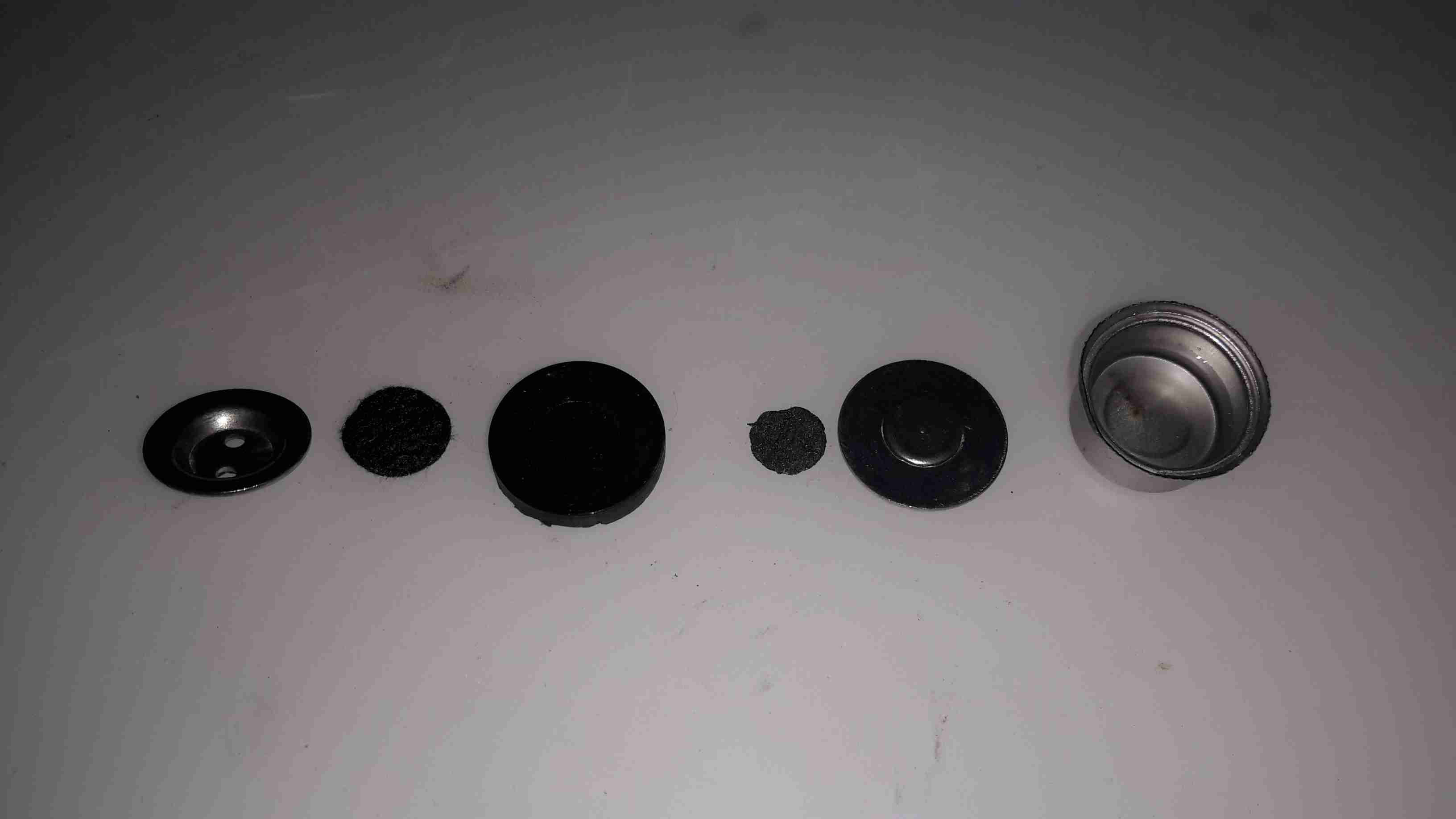
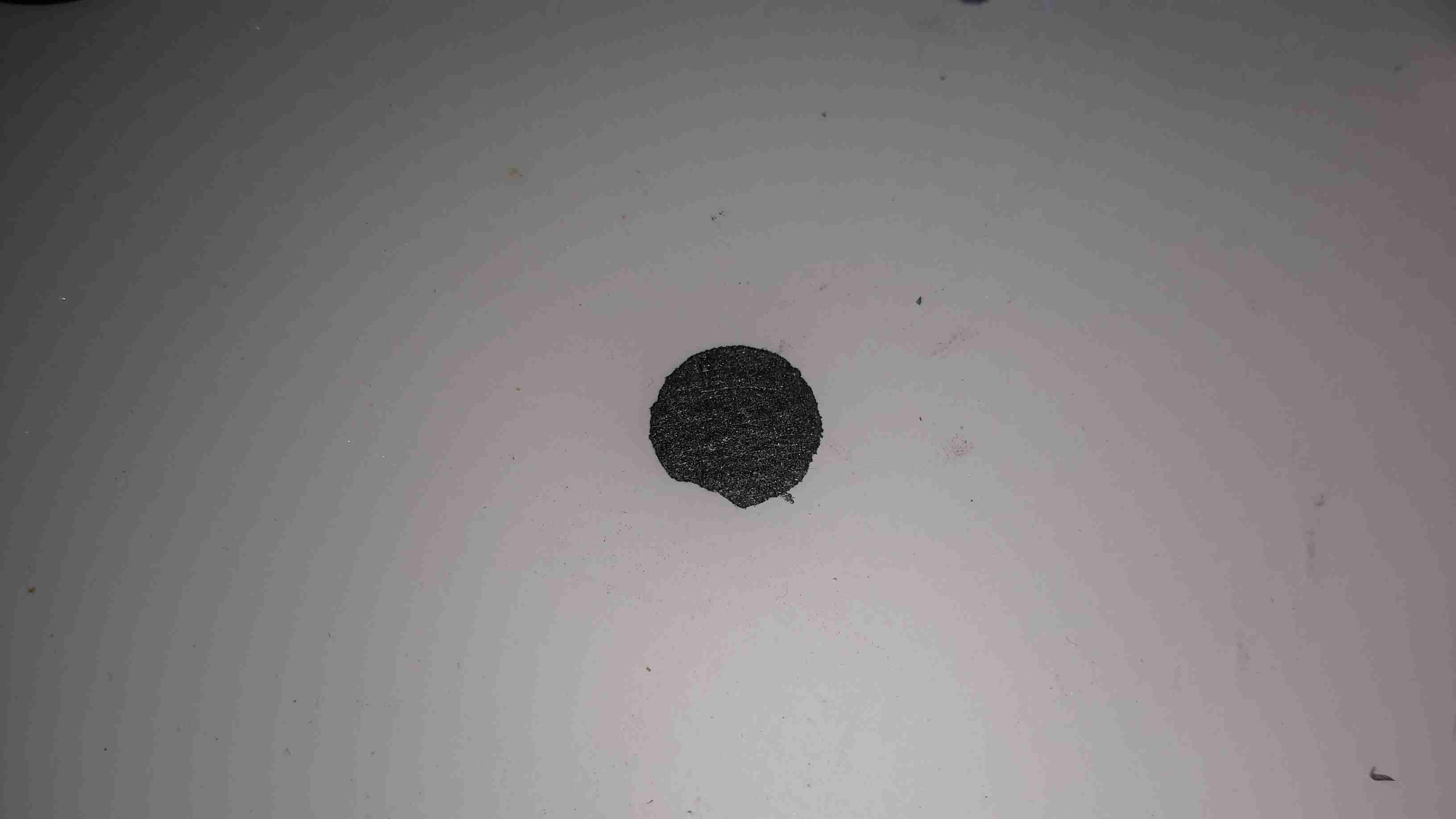
As the CO meter I bought on eBay didn’t register anything whatsoever, I decided I’d hack the sensor itself apart to make sure it wasn’t just an empty steel can. It turns out that it’s not just an empty can, but there are some reasons why the thing doesn’t work 😉
Cell Disassembled
The cell was crimped together under the yellow shrinkwrap, but that’s nothing my aviation snips couldn’t take care of. The photo above shows the components from inside.
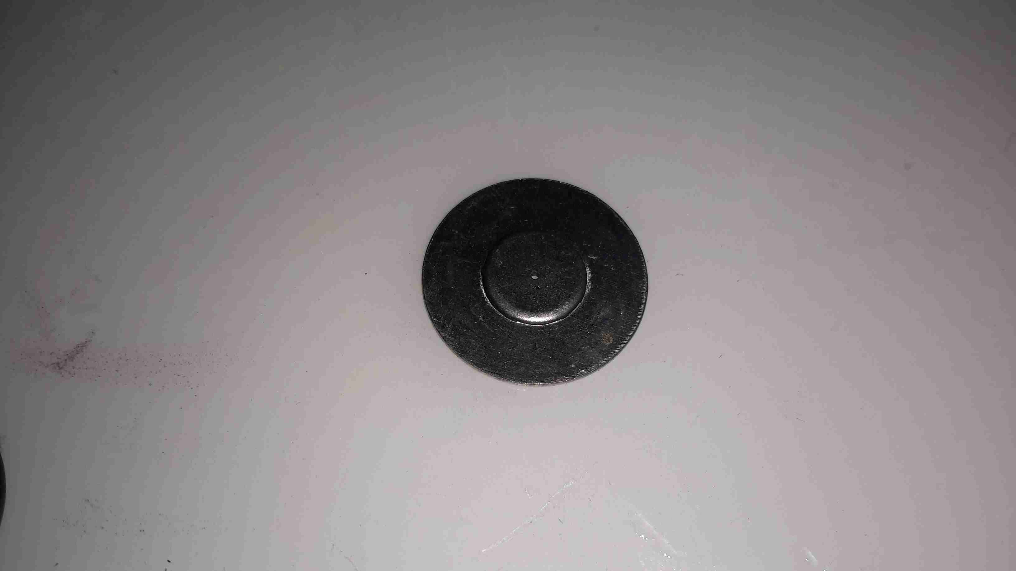
End Cap
The endcap is just a steel pressing, nothing special here.
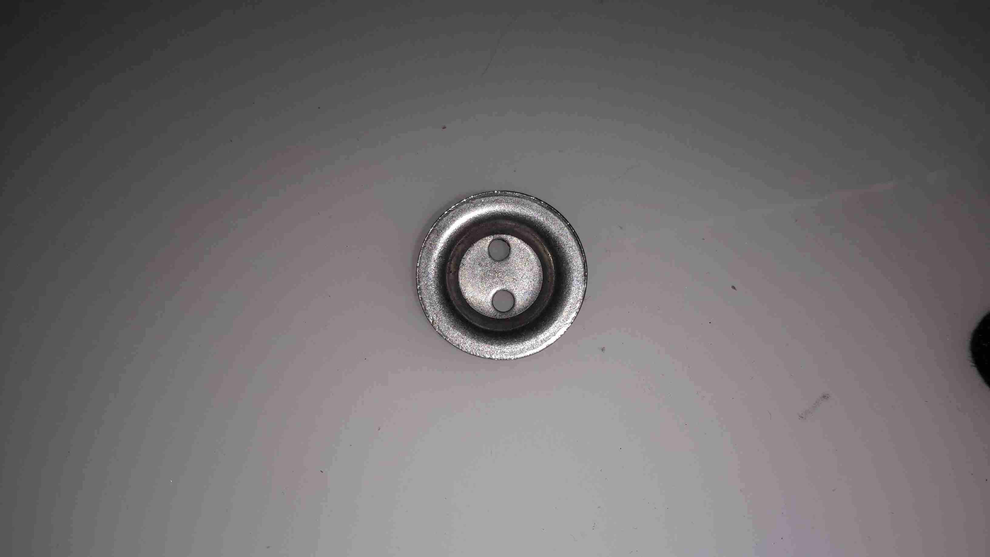
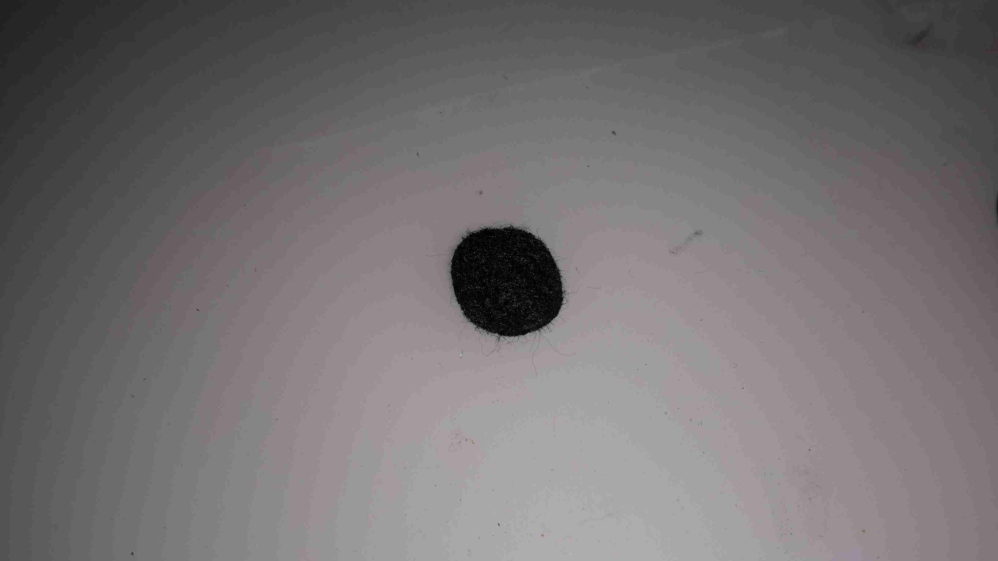
Filter
Also pretty standard is the inlet filter over the tiny hole in the next plate, even though it’s a lot more porous that I’ve seen before in other sensors.
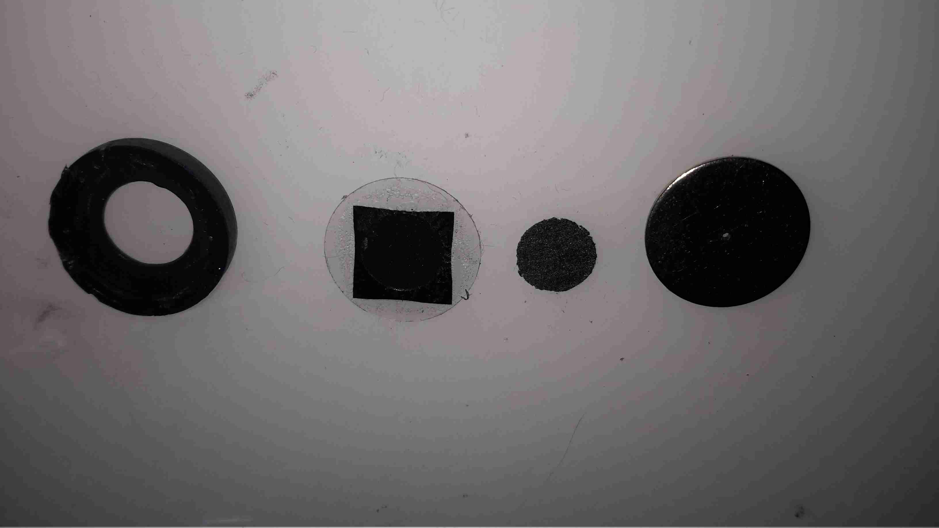
Working Electrode Components
Next up is the working electrode assembly, this also forms the seal on the can when it’s crimped, along with insulating it from the counter electrode & external can. The small disc third from left is supposed to be the electrode, which in these cells should be loaded with Platinum. Considering where else they’ve skimped in this unit, I’ll be very surprised if it’s anything except graphite.
Counter Electrode
Next up is the counter electrode, which is identical to the first, working electrode. Again I doubt there’s any precious metals in here.
Backplate
Another steel backplate finishes off the cell itself, and keeps most of the liquid out, just making sure everything stays moist.
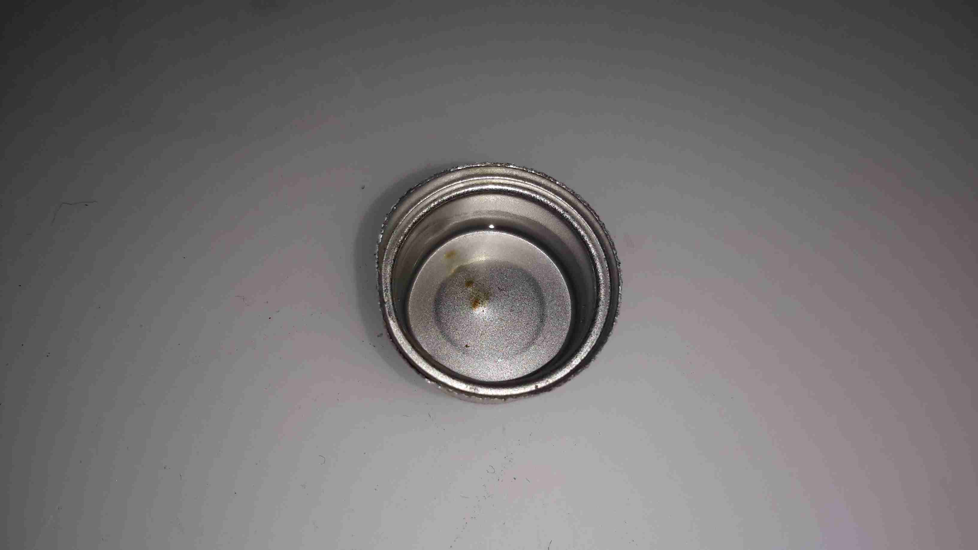
Rear Can & Reservoir
Finally, the rear of the cell holds the reservoir of liquid electrolyte. This is supposed to be Sulphuric Acid, but yet again they’ve skimped on the cost, and it’s just WATER.
It’s now not surprising that it wouldn’t give me any readings, this cell never would have worked correctly, if at all, without the correct electrolyte. These cheap alarms are dangerous, as people will trust it to alert them to high CO levels, when in fact it’s nothing more than a fancy flashing LED with an LCD display.
Ironically enough, when I connected a real electrochemical CO detector cell to the circuit from the alarm, it started working, detecting CO given off from a burning Butane lighter. It wouldn’t be calibrated, but it proves everything electronic is there & operational. It’s not surprising that the corner cut in this instance is on the sensor cell, as they contain precious metals & require careful manufacturing it’s where the cost lies with these alarms.
I did a little more digging into the PSU circuitry of the small coin counting machine, and it’s even more strange than I thought!
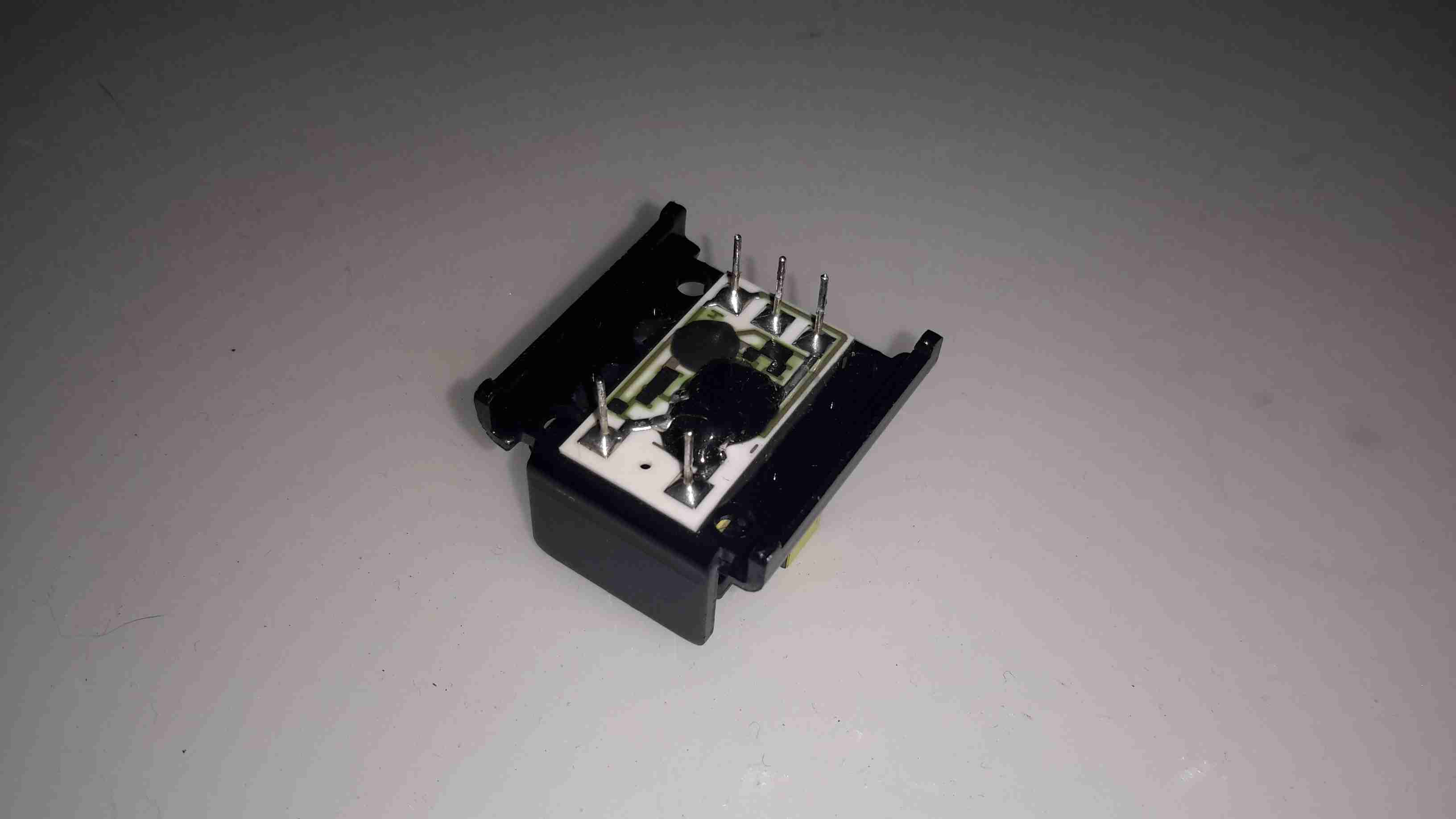
The part I originally thought was a transformer on the PSU board is in fact a DC-DC converter module!
DC-DC Converter
Here’s the device after desoldering it from the PCB. It turns out that instead of a transformer, it’s an inductor.
Hiding Control Electronics
Underneath is the controller electronics, with an COB controller & the switching transistors are under a protective covering of silicone.
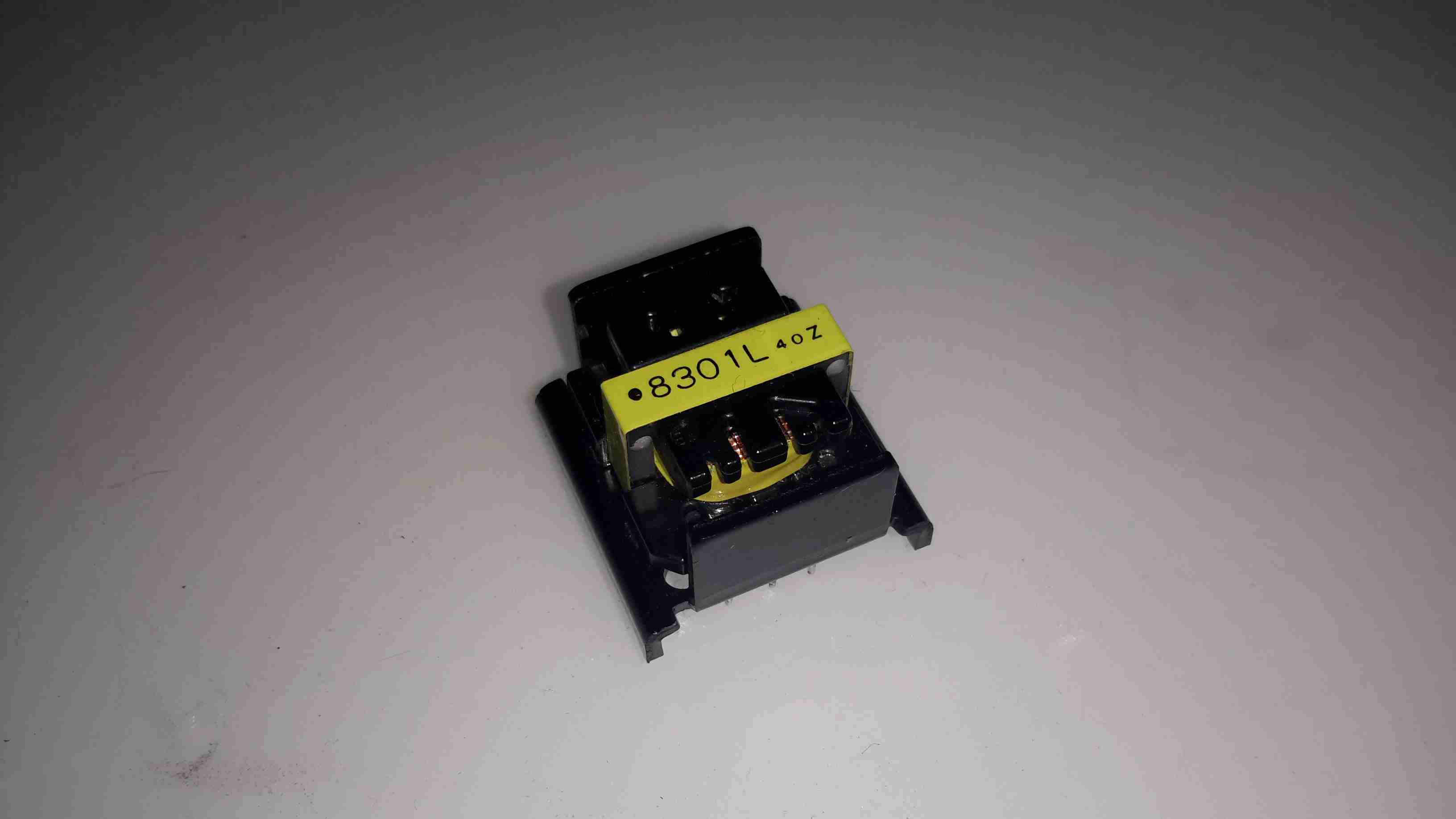
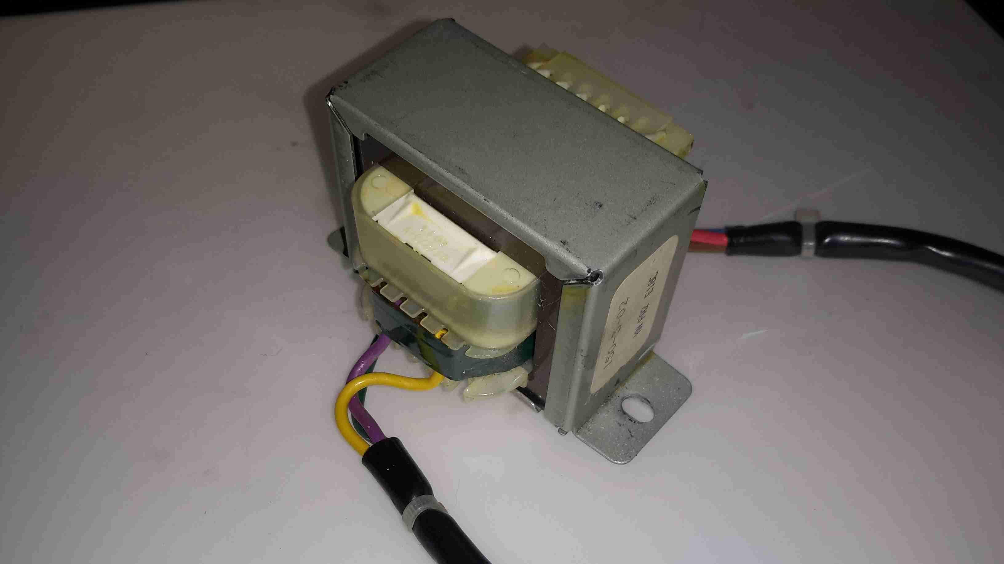
Mains Transformer
Driving this whole lot of PSU randomness is the mains transformer, with a secondary voltage of 35v.
The only reason I can think of that the manufacturer went to this much expense with the power supply is stability – a coin counting machine that miscounts due to power supply surges, sags & spikes wouldn’t be very much use. It’s not likely I’ll see anything similar again, unless I manage to get hold of something like medical grade equipment.
Here’s some teardown photos of an old De La Rue coin counter, used in businesses for rapid counting of change into large bags.
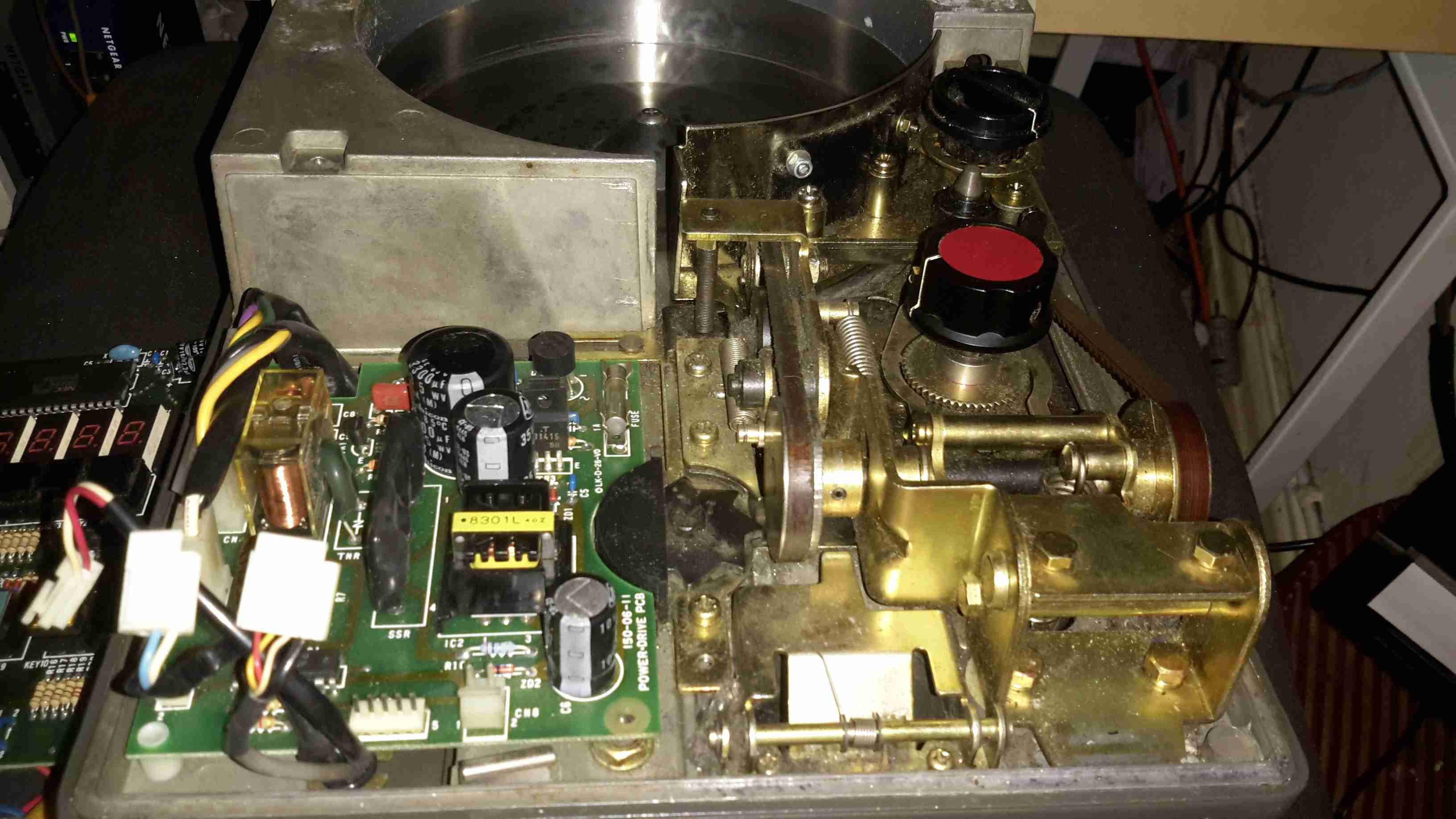
Mechanism
An overview of the whole mechanical system of the counter. Coins are loaded into the drum at the rear of the machine, which sorts them into a row for the rubber belt to pick up & run through the counter. The coin type to be sorted is selected by turning the control knobs on the right.
The control knobs adjust the width & height of the coin channel so only the correct sized coins will be counted.
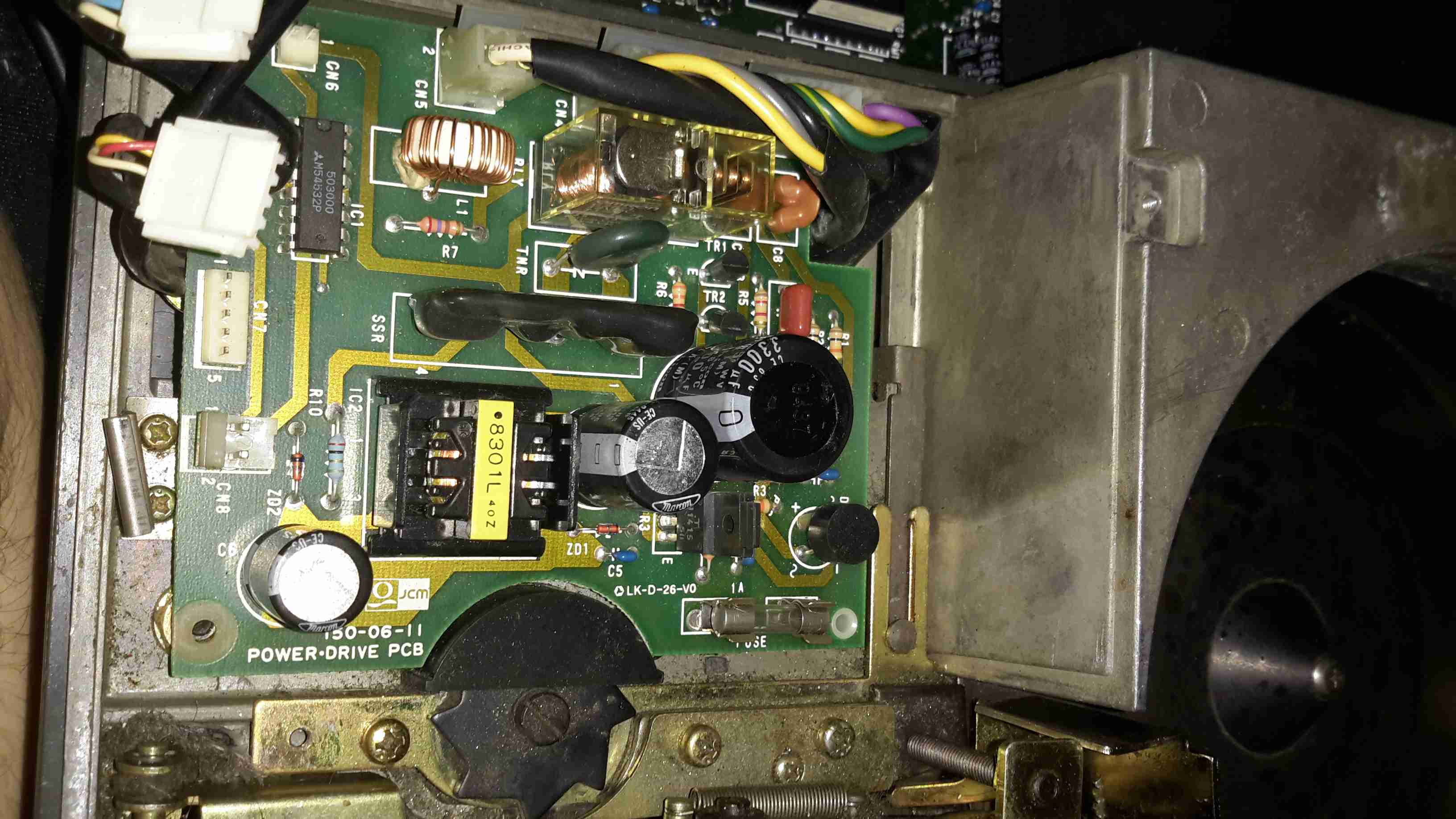
PSU & Switching
The counter is driven by a basic AC induction motor, the motor power relay & reversing relay is on this PCB, along with the 5v switching supply for the main CPU board.
The SMPS on this board looks like a standard mains unit, but it’s got one big difference. Under the frame next to the main motor is a relatively large transformer, with a 35v output. This AC is fed into the SMPS section of the PSU board to be converted to 5v DC for the logic.
I’m not sure why it’s been done this way, and have never seen anything similar before.
The edge of the coin channel can be seen here, the black star wheel rotates when a coin passes & registers the count.
Controller PCB
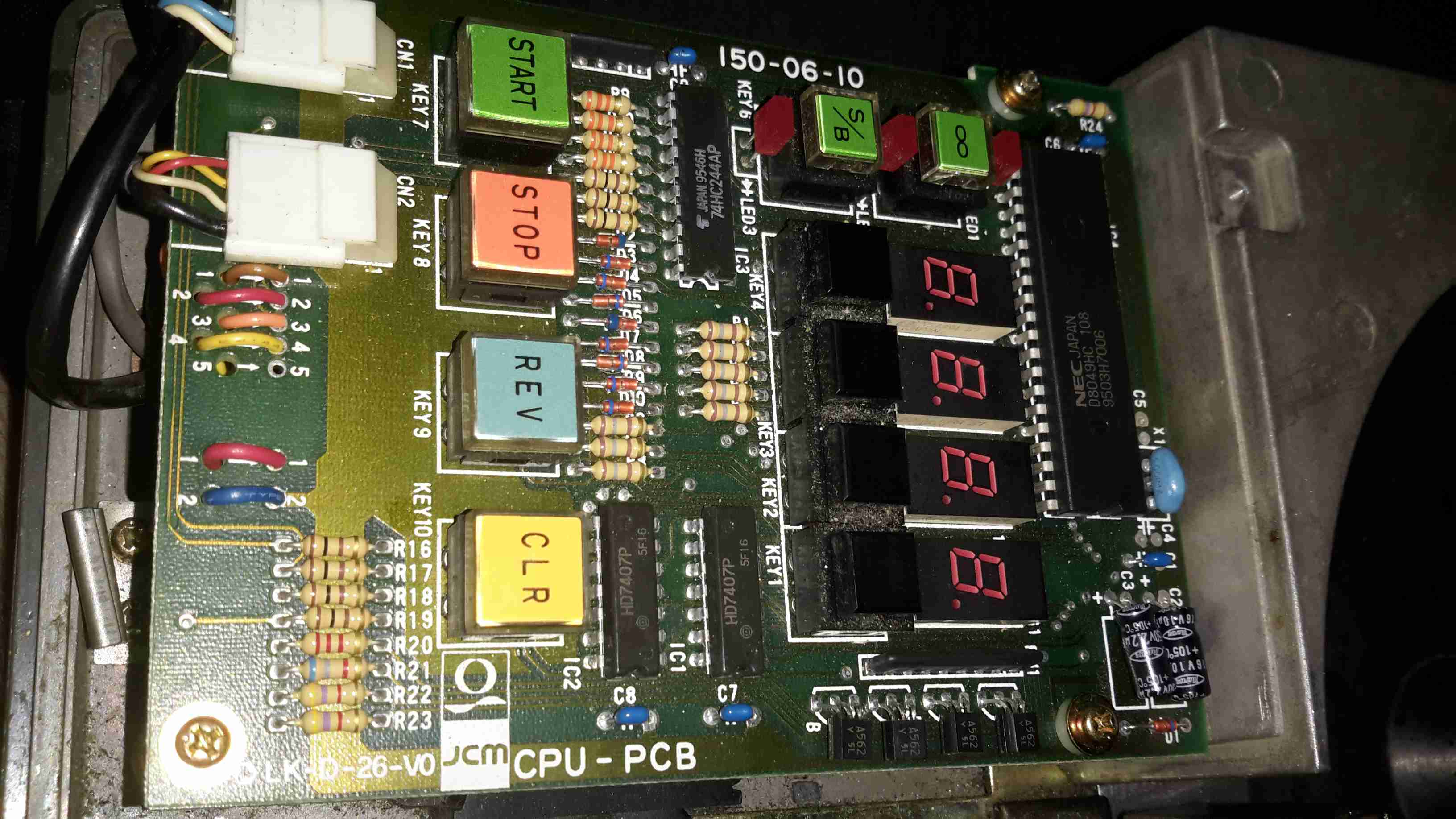
Here’s the main controller PCB, IC date codes put the unit to about 1995. The main CPU is a NEC UPD8049HC 8-bit micro, no flash or EEPROM on this old CPU, simply mask ROM. Coin readout is done on the 4 7-segment LED displays. Not much to this counter, it’s both electronically & mechanically simple.
Counter Sensor
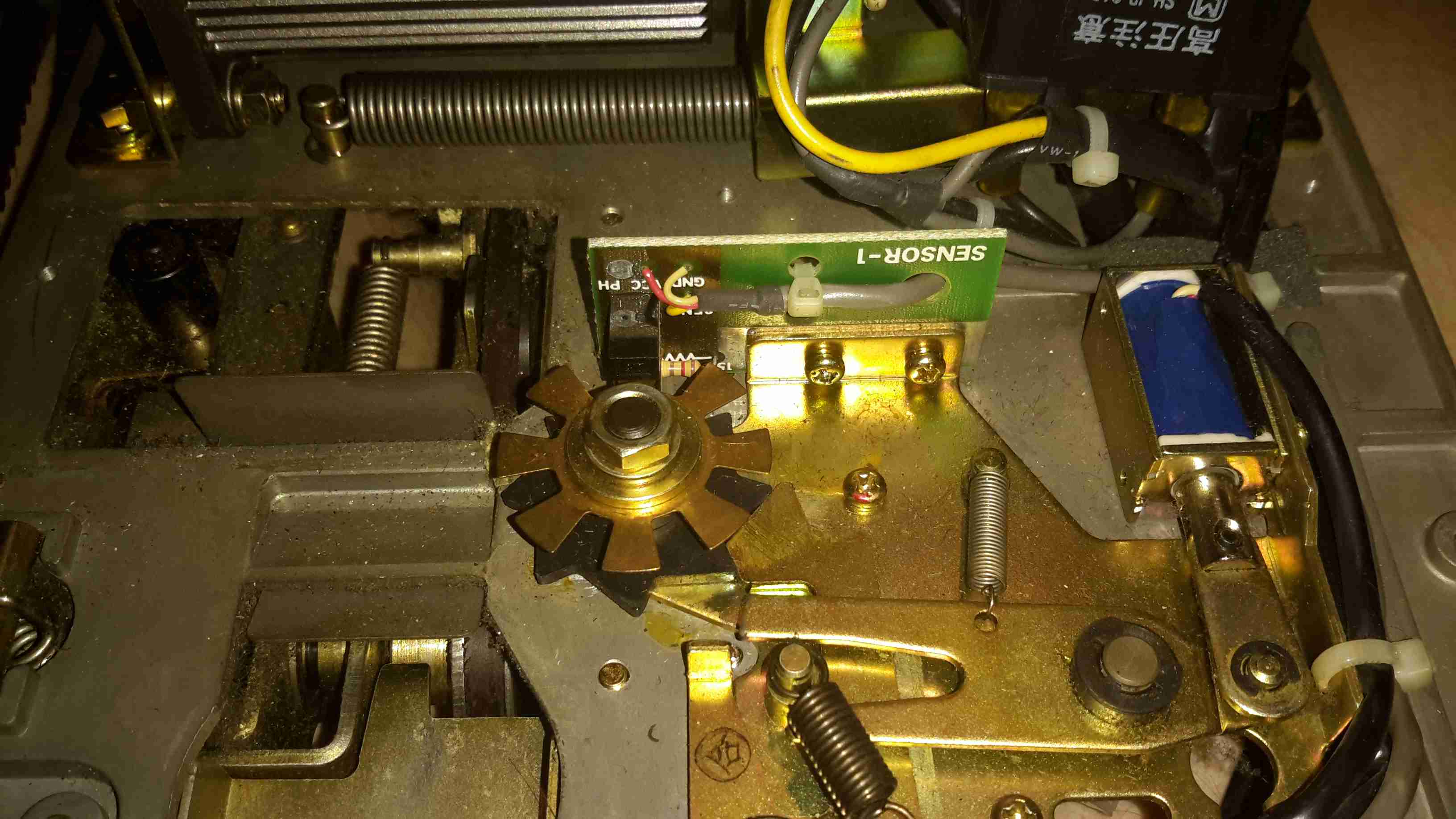
Coin counting is done by the star wheel mentioned above, which drives the interrupter disc on this photo-gate. The solenoid locks the counter shaft to prevent over or under counting when a set number of coins is to be counted.
Motor Run Capacitor
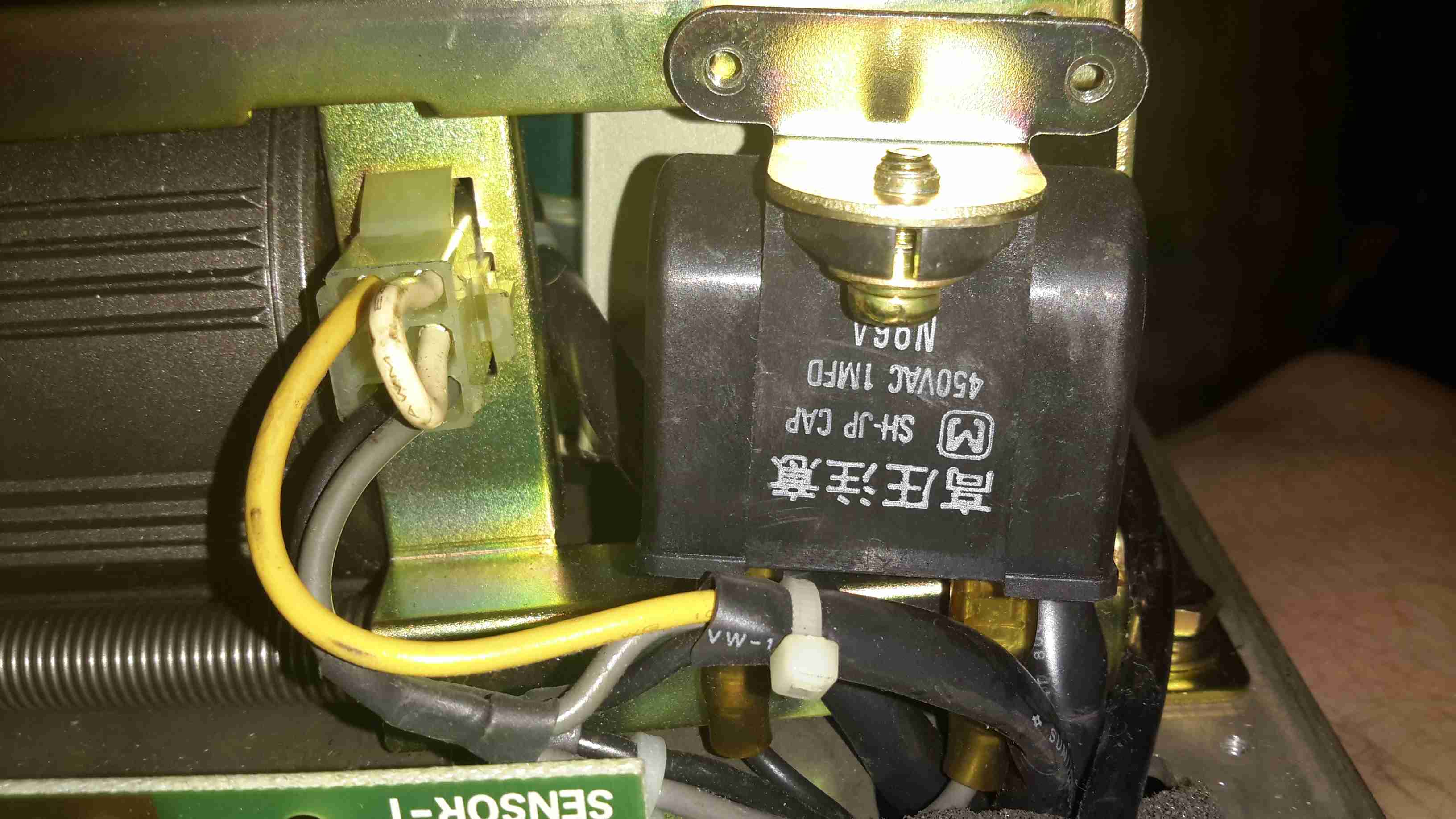
Under the frame, here on the left is the small induction motor, only 6W, 4-pole. The run cap for the motor is in the centre, and the 35v transformer is just visible behind it.
Main Motor Drive
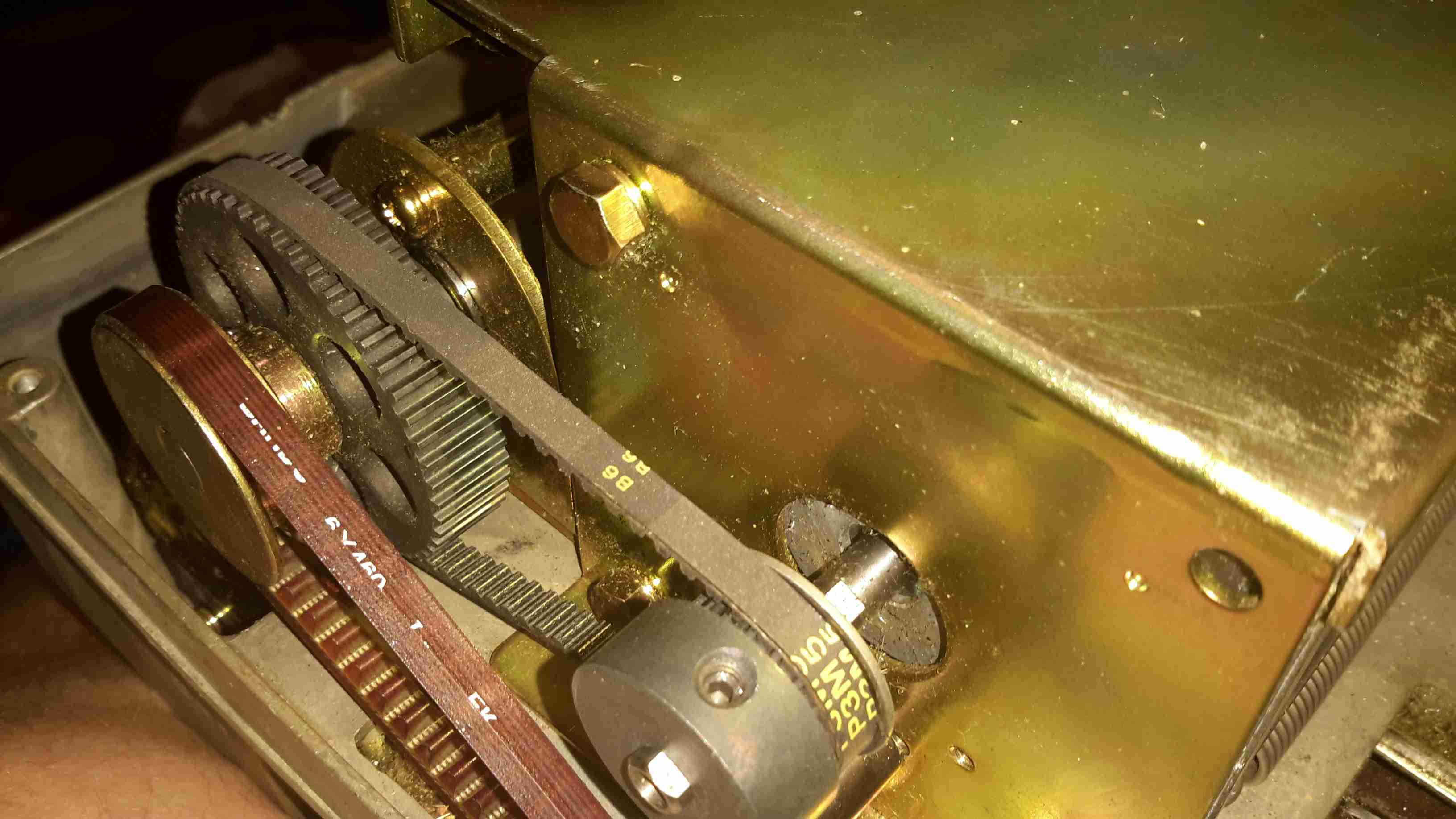
Main drive to the coin sorting mech is through rubber belts, and bevel gears drive the coin drum.
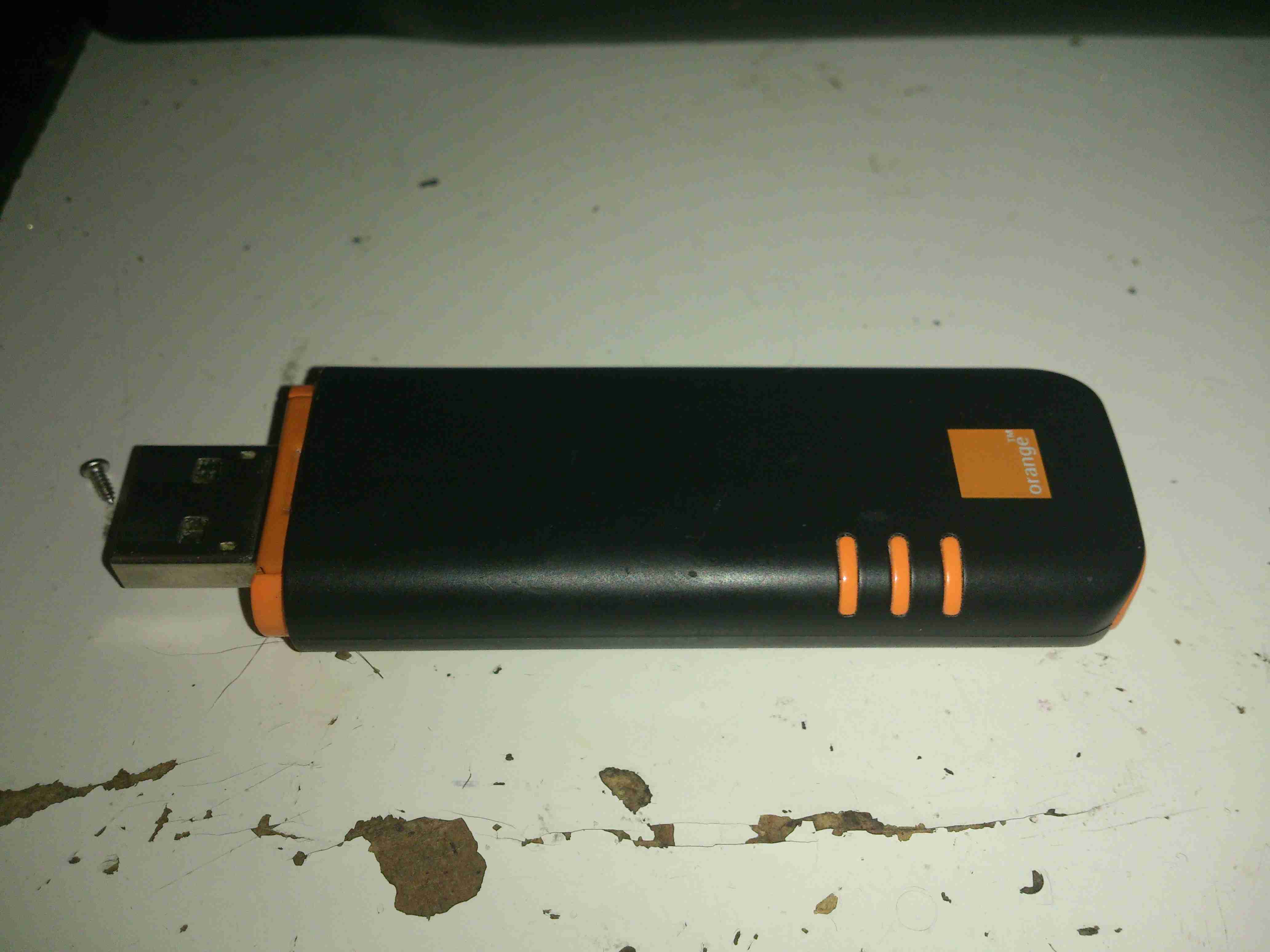
Here’s an old HDSPA 3G USB modem stick that I got with a mobile phone contact many years ago. As it’s now very old tech, and I have a faster modem, not to mention that I’m no longer with Orange (Robbing <expletive>), here’s a teardown of the device!
Cover Removed
The top shell is just clipped into place, while a pair of very small screws hold down the orange piece at left to hold the PCB stack in the casing. Not much to see here, but it’s clear that there’s a lot crammed into a very small space.
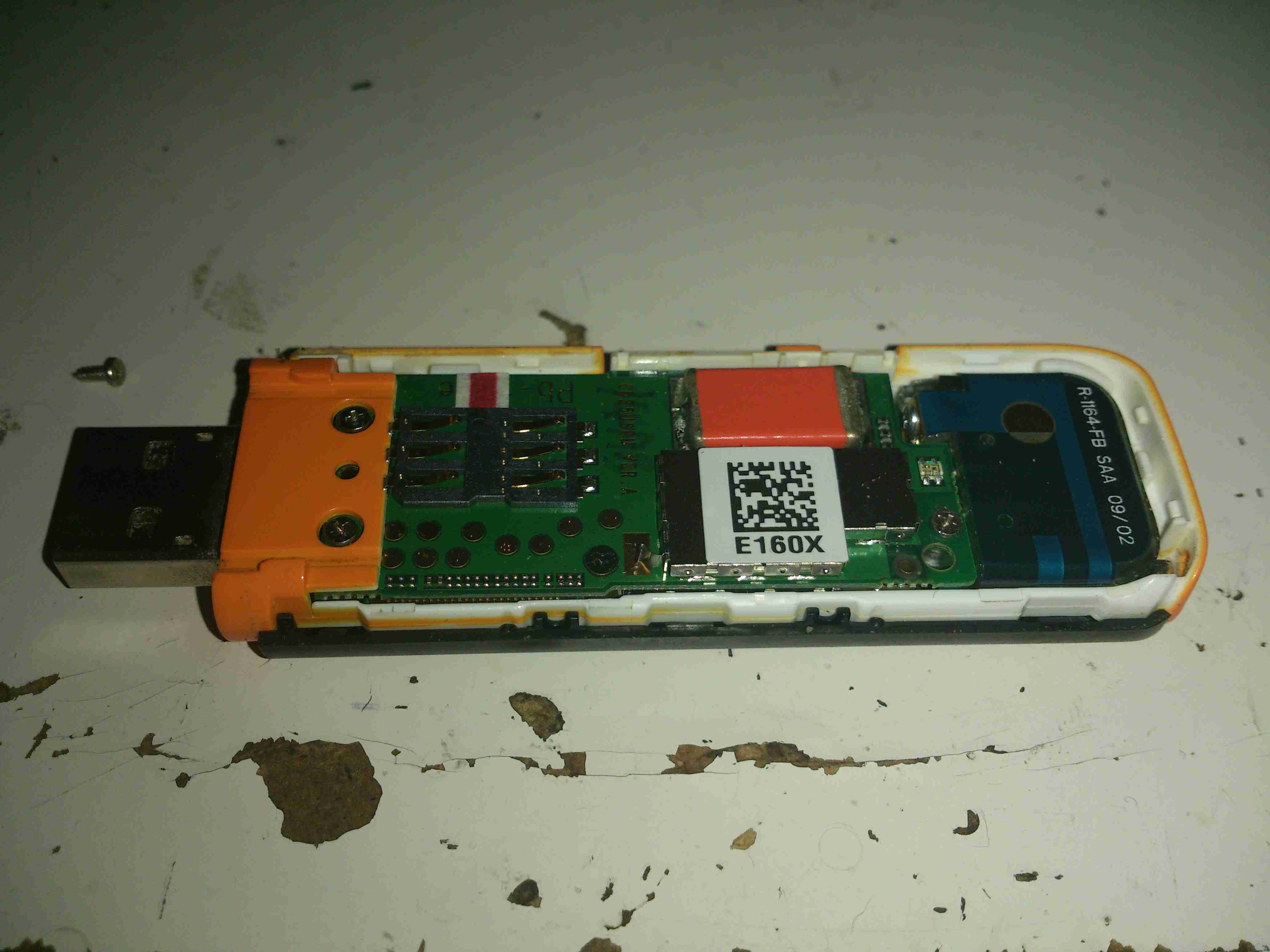
PCB Assembly
Here’s the PCB stack removed from the outer casing. The main antenna is on the right, attached with another small screw. Every IC on the boards is covered with an RF can. No problems there, pliers to the rescue!
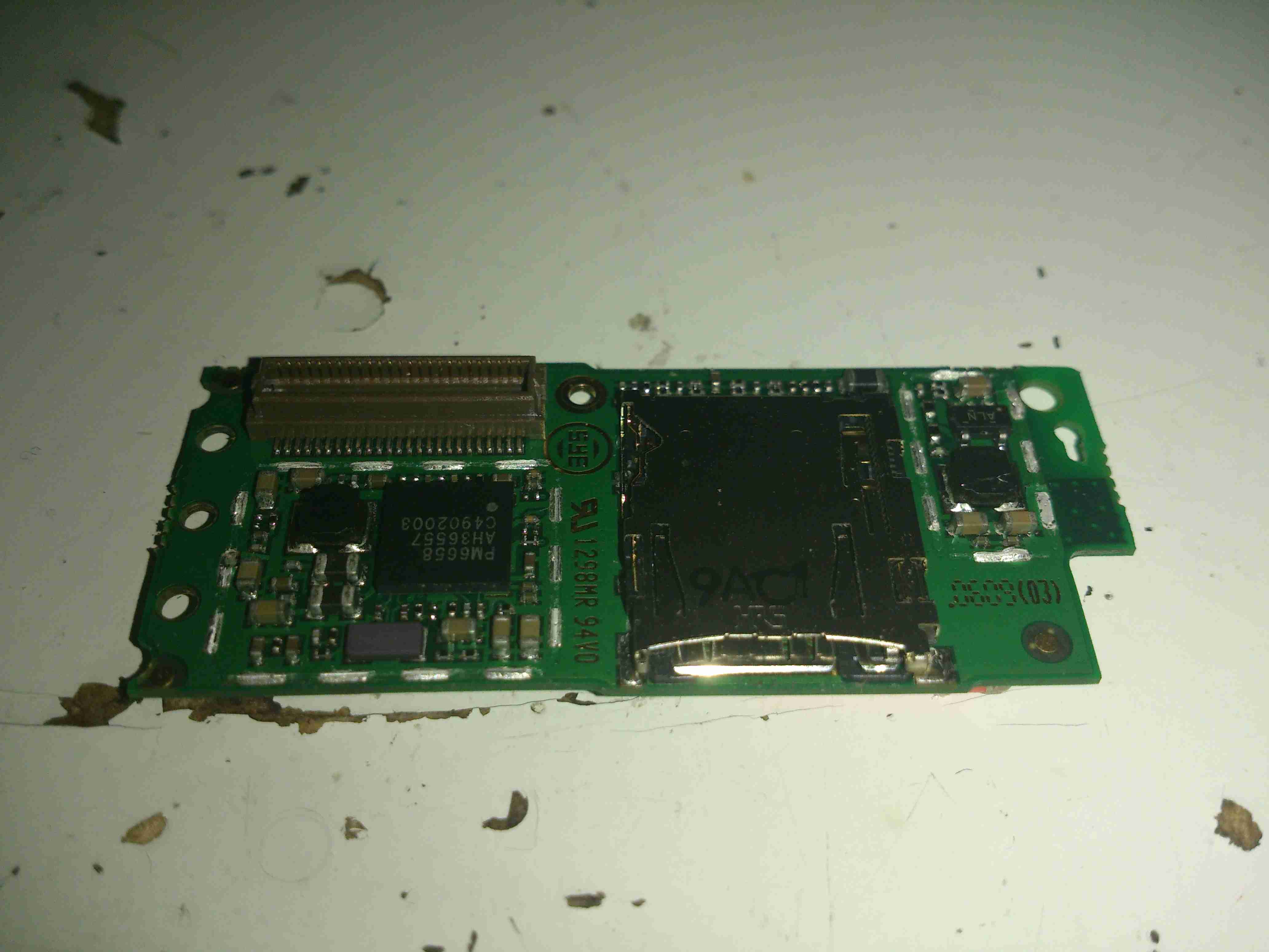
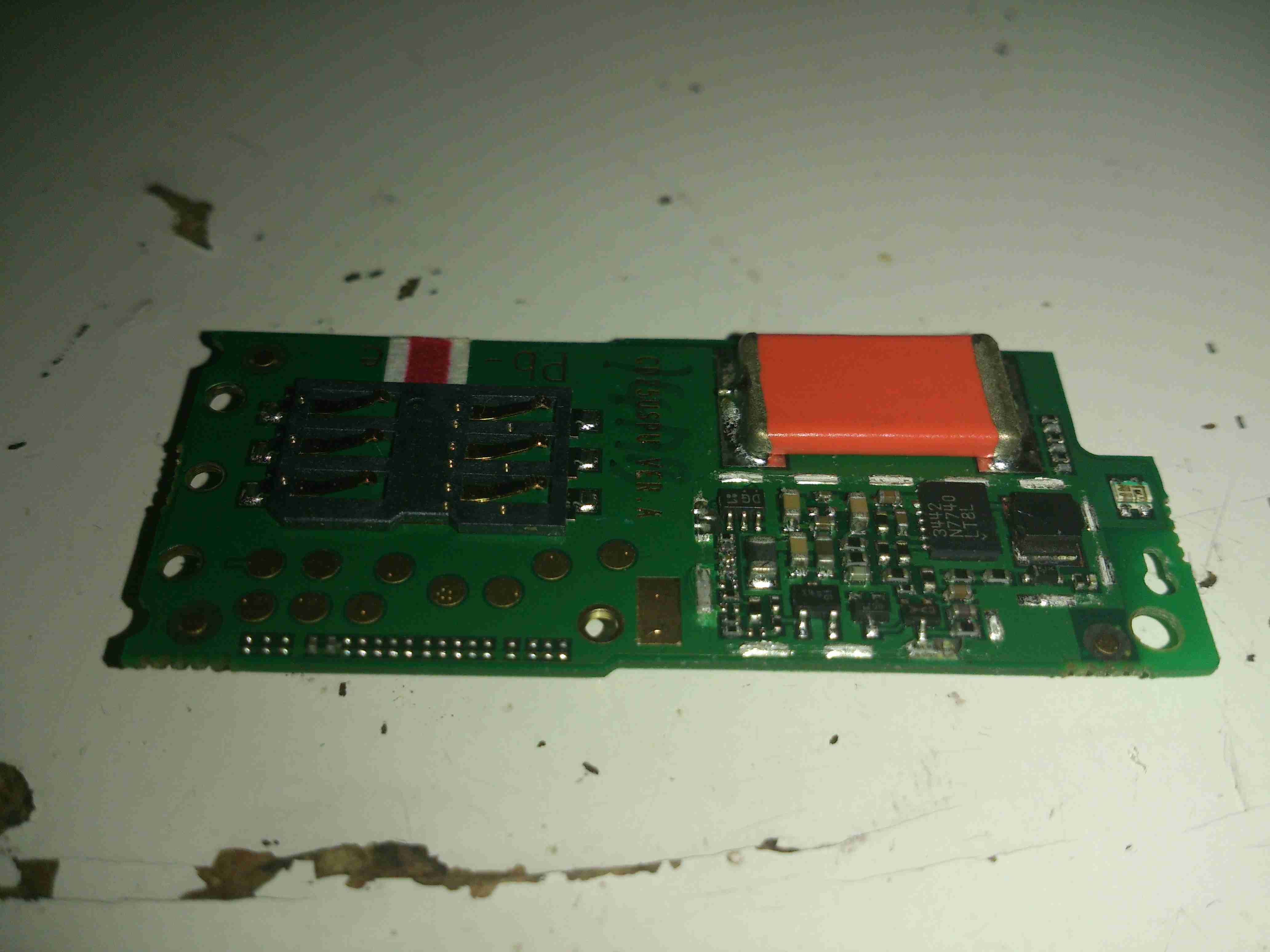
SD Card Slot
Here’s the top PCB, all the shields have been removed. On the left is a Qualcomm PM6658 Power Management IC with integrated USB transceiver. This is surrounded by many of the power management circuits.
The integrated SD Card slot is on the right side. with what looks to be a local switching regulator for supply voltage. This might also provide the SIM card with it’s power supply.
PSU & SIM Contacts
The other side of the top board reveals more power management, with another switching regulator, and a truly massive capacitor at the top edge. I’m guessing this is a solid Tantalum.
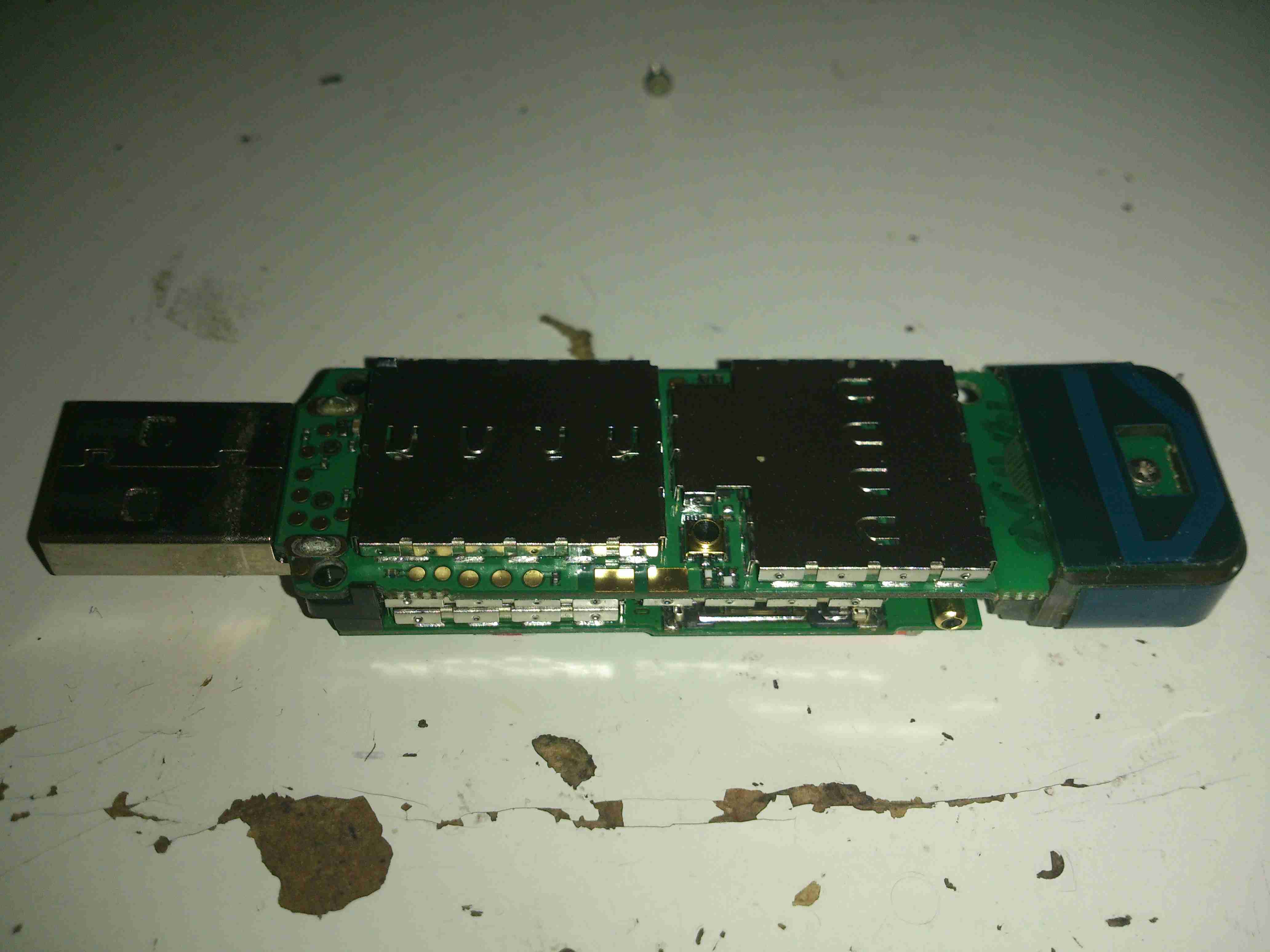
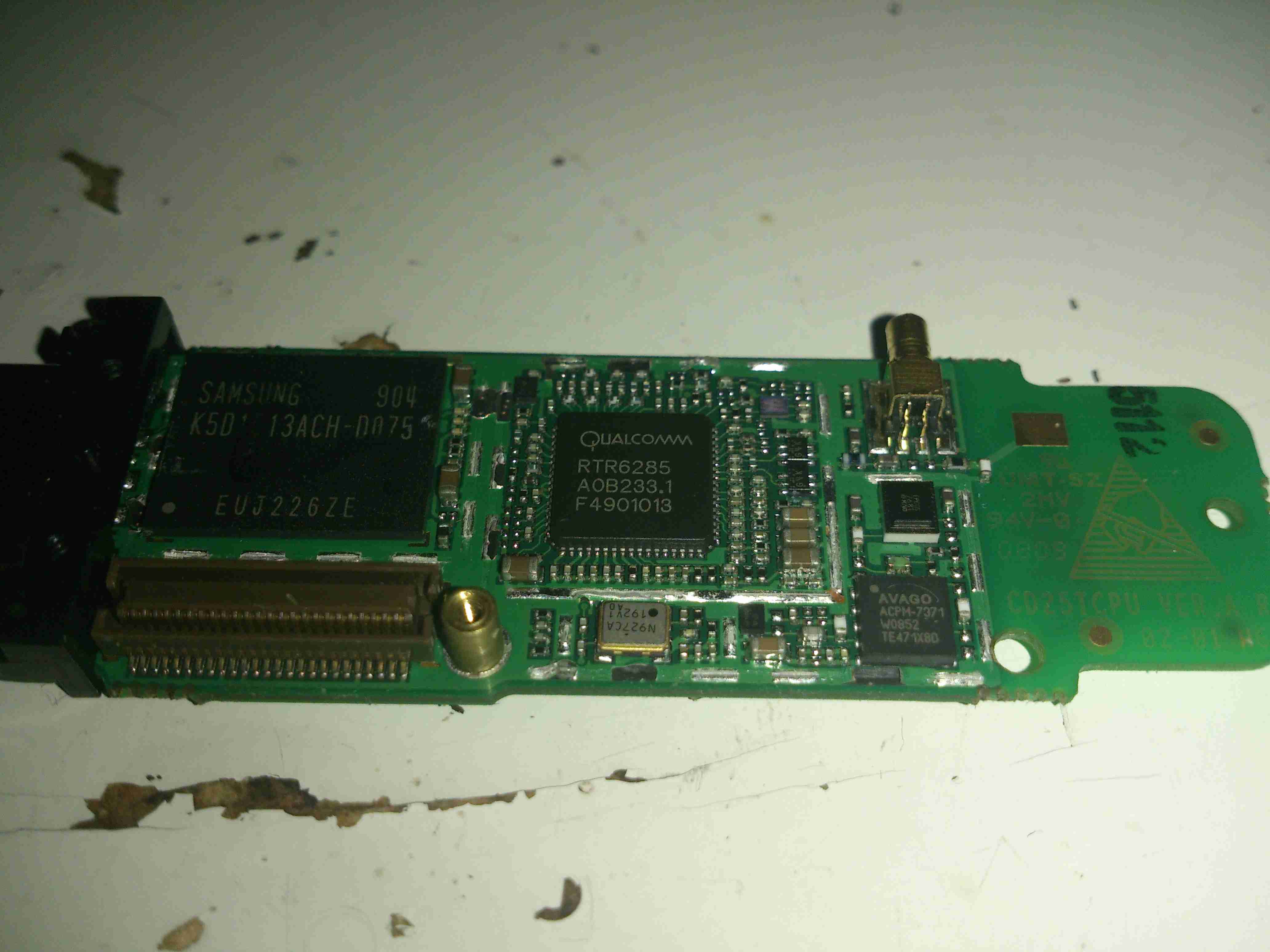
Main Chipset PCB
The other PCB holds the main chipset & RF circuits. On the left here is a Samsung MCP K5D1G13ACH IC. This one is a multiple chip package, having 1Gbit of NAND Flash & 512Mbit of mobile SDRAM.
To it’s right is a Qualcomm RTR6285 RF Transceiver. This IC supports multiband GSM/EDGE/UMTS frequencies & also has a GPS receive amplifier included.
At bottom right is an Avago ACPM7371 Wide-Band 4×4 CDMA Power Amplifier. The external antenna connector is top right.
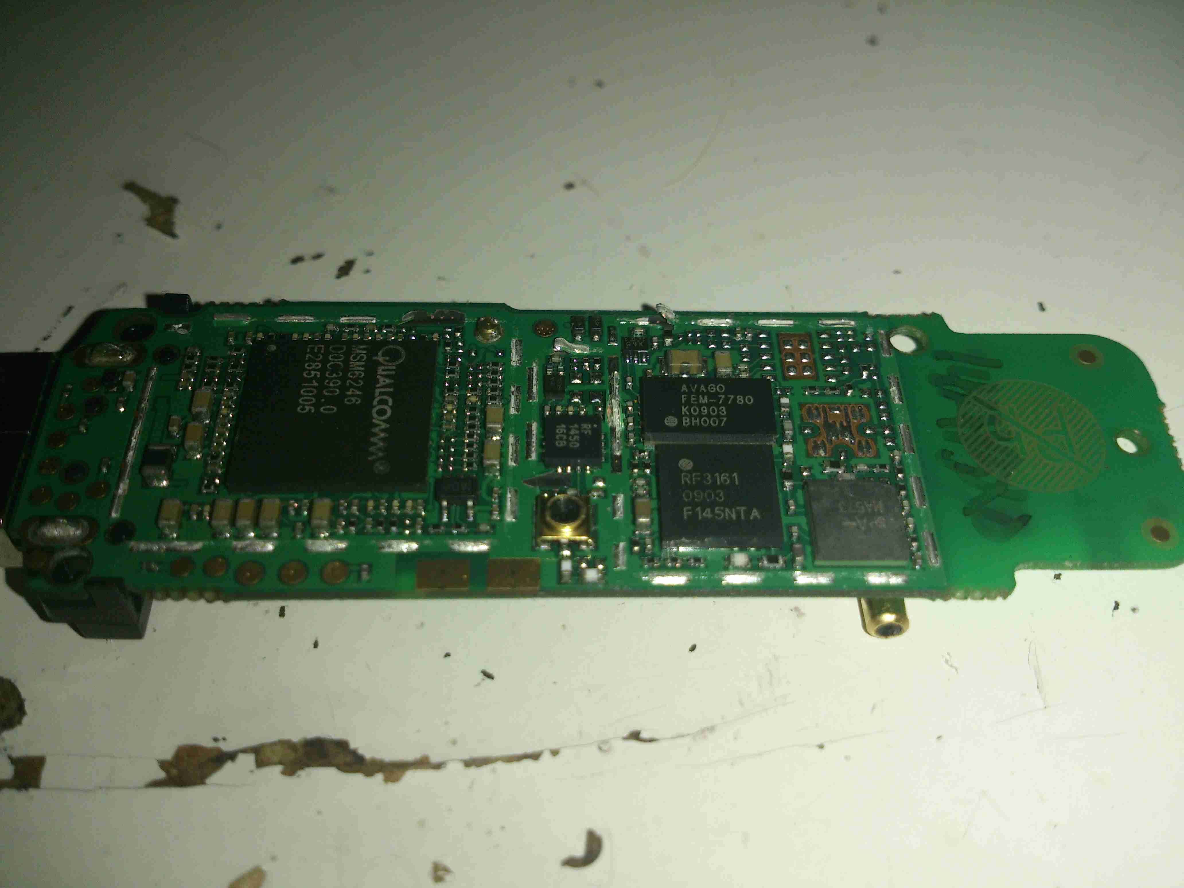
Main Chipset PCB Reverse
On the other side of the main PCB is a Qualcomm MSM6246 Baseband processor. Not sure about this one as I can’t find anything resembling a datasheet. Another micro-coax connector is in the centre, probably for factory test purposes, as it’s not accessible from the outside.
Just above the coax connector is a Qorvo RF1450 SP4T (single-pole 4-throw) High Power (34.5dBm) GSM RF Switch.
Upper right is an Avago FEM-7780 UMTS2100 4×7 Front End Module.
Under that is an RFMD RF3163 Quad-Band RF Power Amplifier Module.
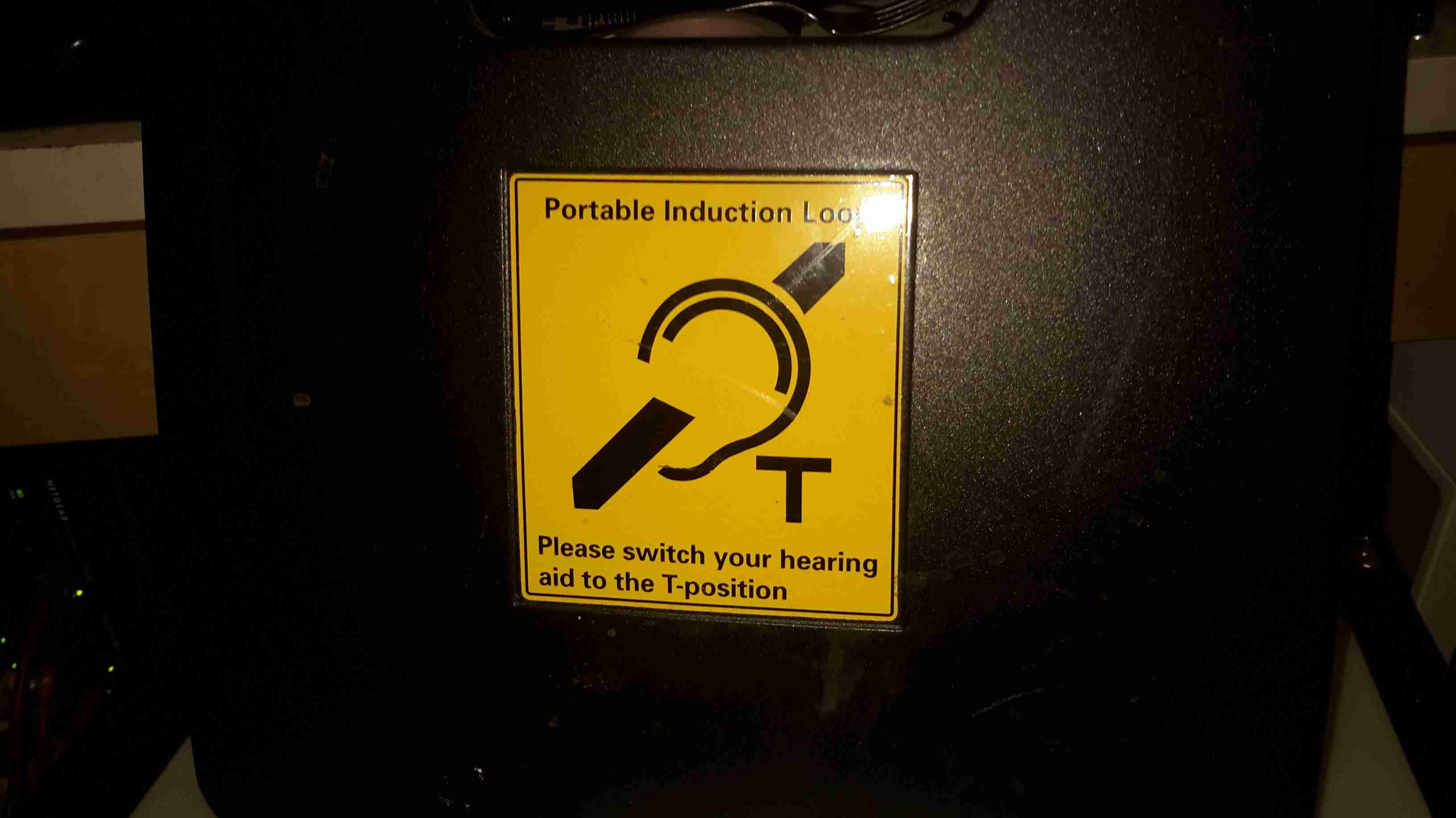
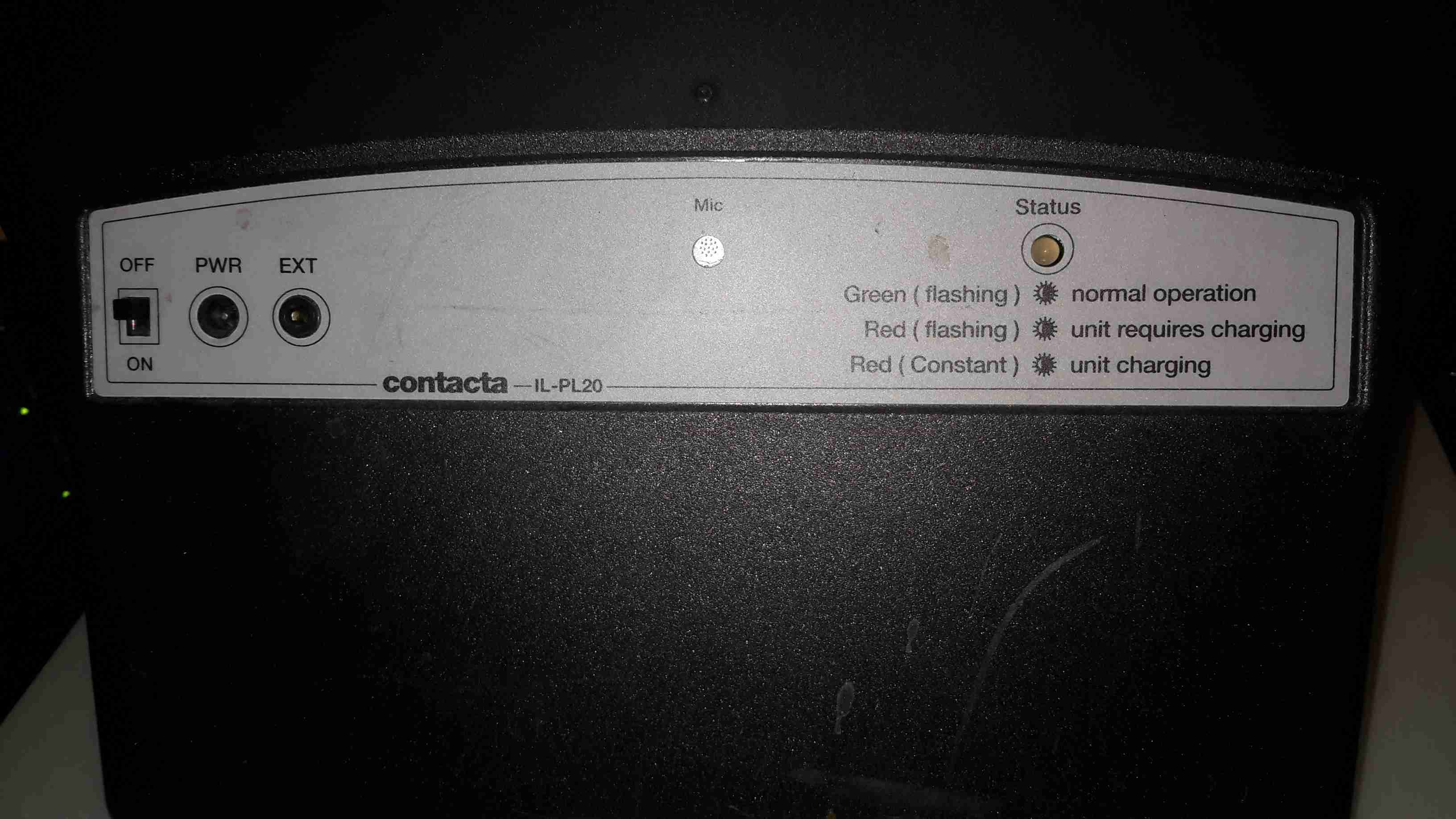
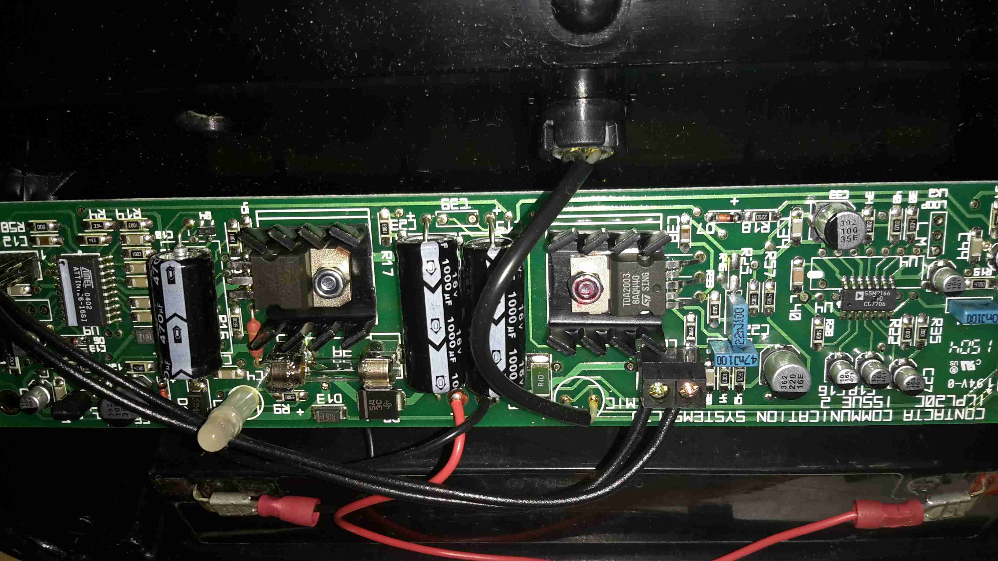
These units are used to broadcast local audio, such as from a public address system or local microphone. They accomplish this by producing a modulated magnetic field that a hearing aid is capable of picking up.
Back Panel
Not many controls on this bit of equipment. A bi-colour LED for status indications, a microphone, external audio input, charging input & a power switch.
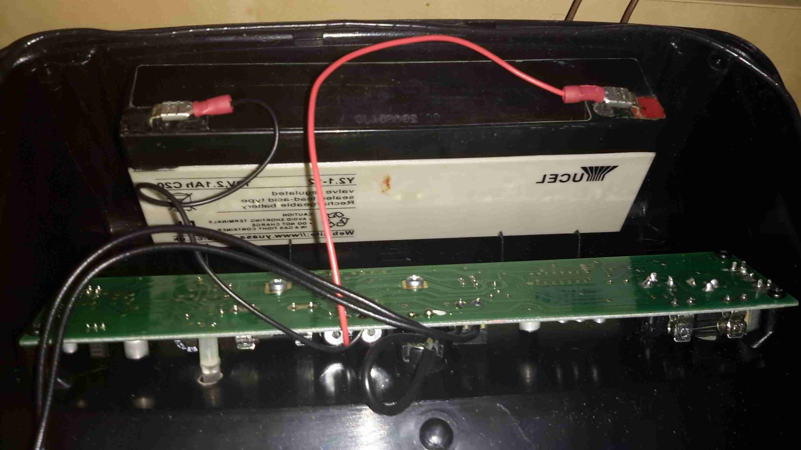
Internals
Popping the cover off reveals a small lead-acid battery, 2.1Ah at 12v. This is used when the loop is unplugged.
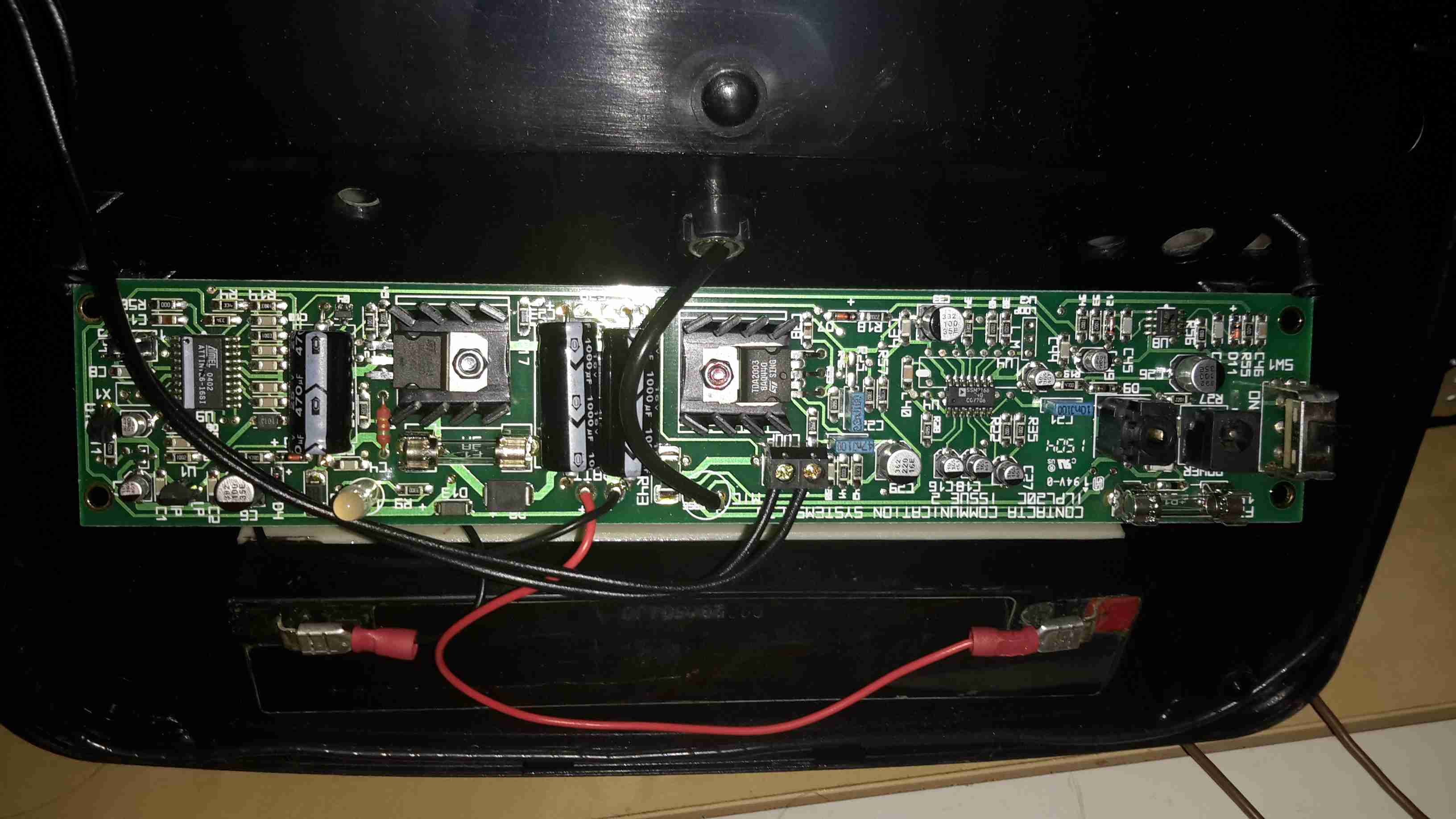
Main PCB
Here’s the main PCB, which takes care of the audio & battery charging. The inductive loop itself is just visible as the tape-covered wire bundle around the edge of the casing.
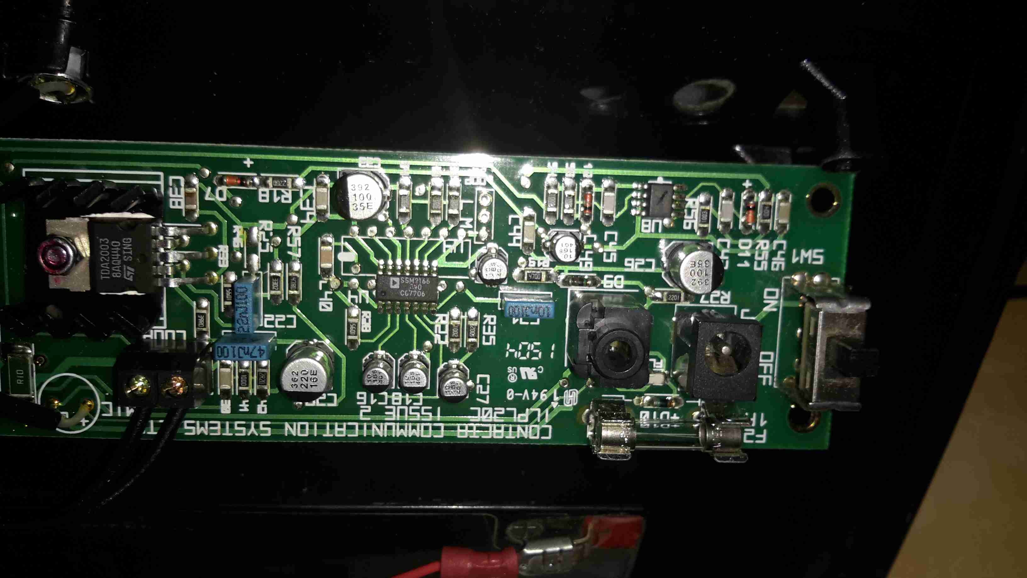
Audio & Power Input
Here’s the input section of the main PCB. The microphone input is handled by a SSM2166 front-end preamplifier from Analog Devices.
Power Amplifier
This audio is then fed into a TDA2003 10W Mono Power Amplifier IC, which directly drives the induction coil as if it were a speaker. Any suitable receiving coil & amplifier can then receive the signal & change it back into audio.
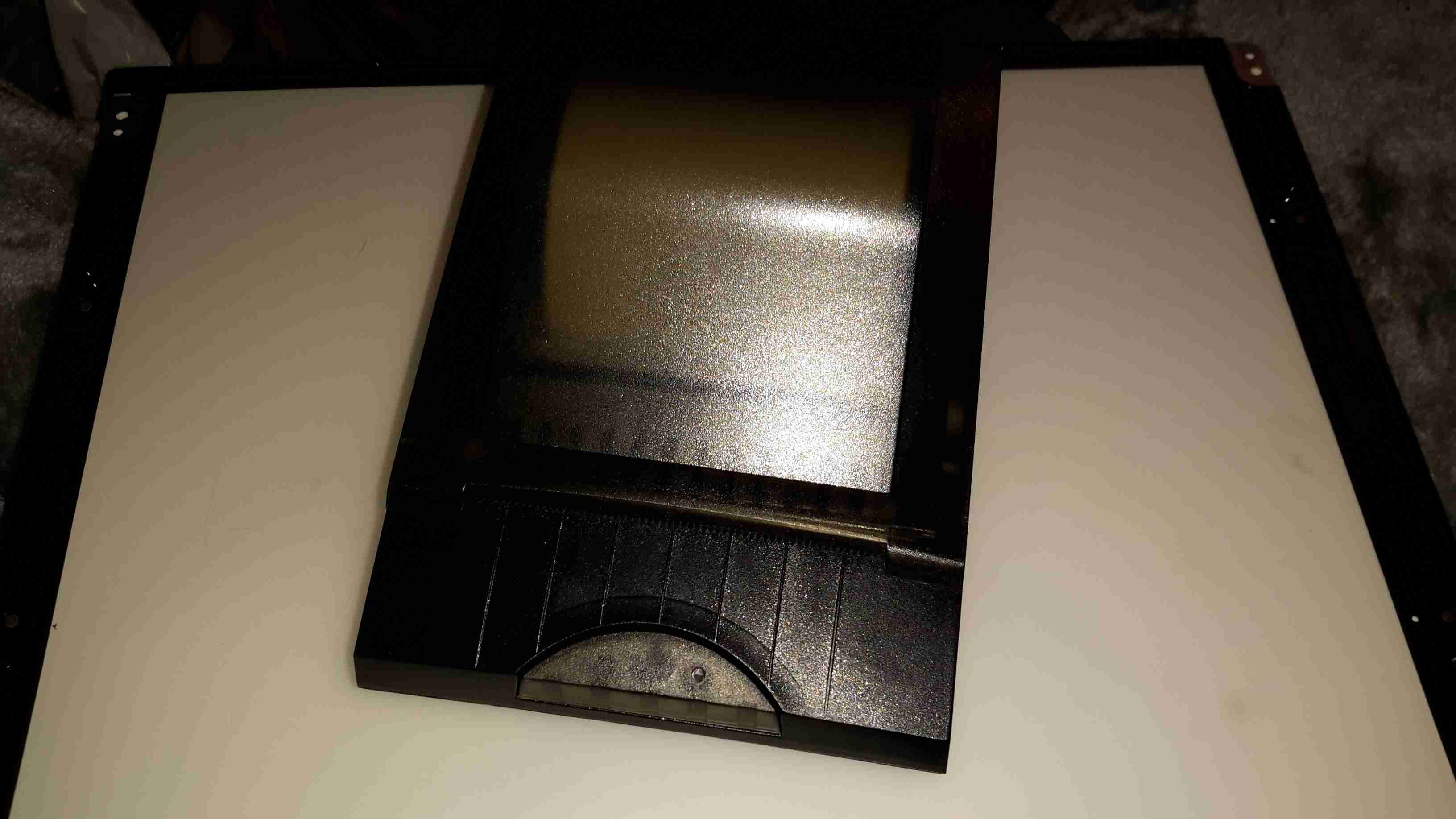
I have yet another receipt printer, this one appears to be brand new. It’s possibly the smallest thermal 80mm printer I have at the moment, and has both USB & Serial interfaces.
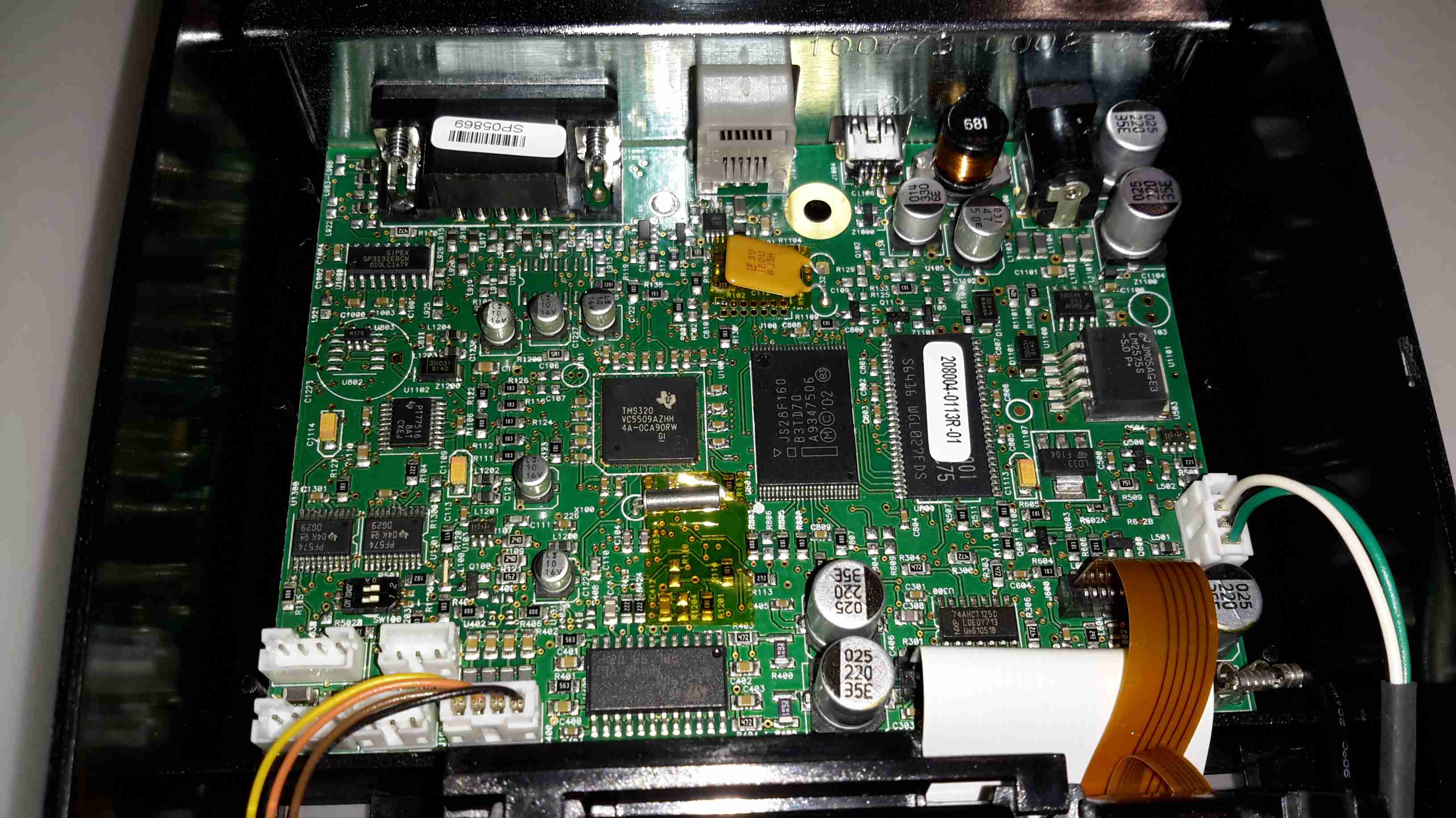
Controller PCB
There’s not much to these printers at all. Removing a single screw allows the case halves to separate, showing the guts. The controller is based around a Texas Instruments TMS320VC5509AFixed-Point DSP. It’s associated Flash ROM & RAM are to the right.
Power supply is dealt with in the top right of the PCB, with the interface ports further left.
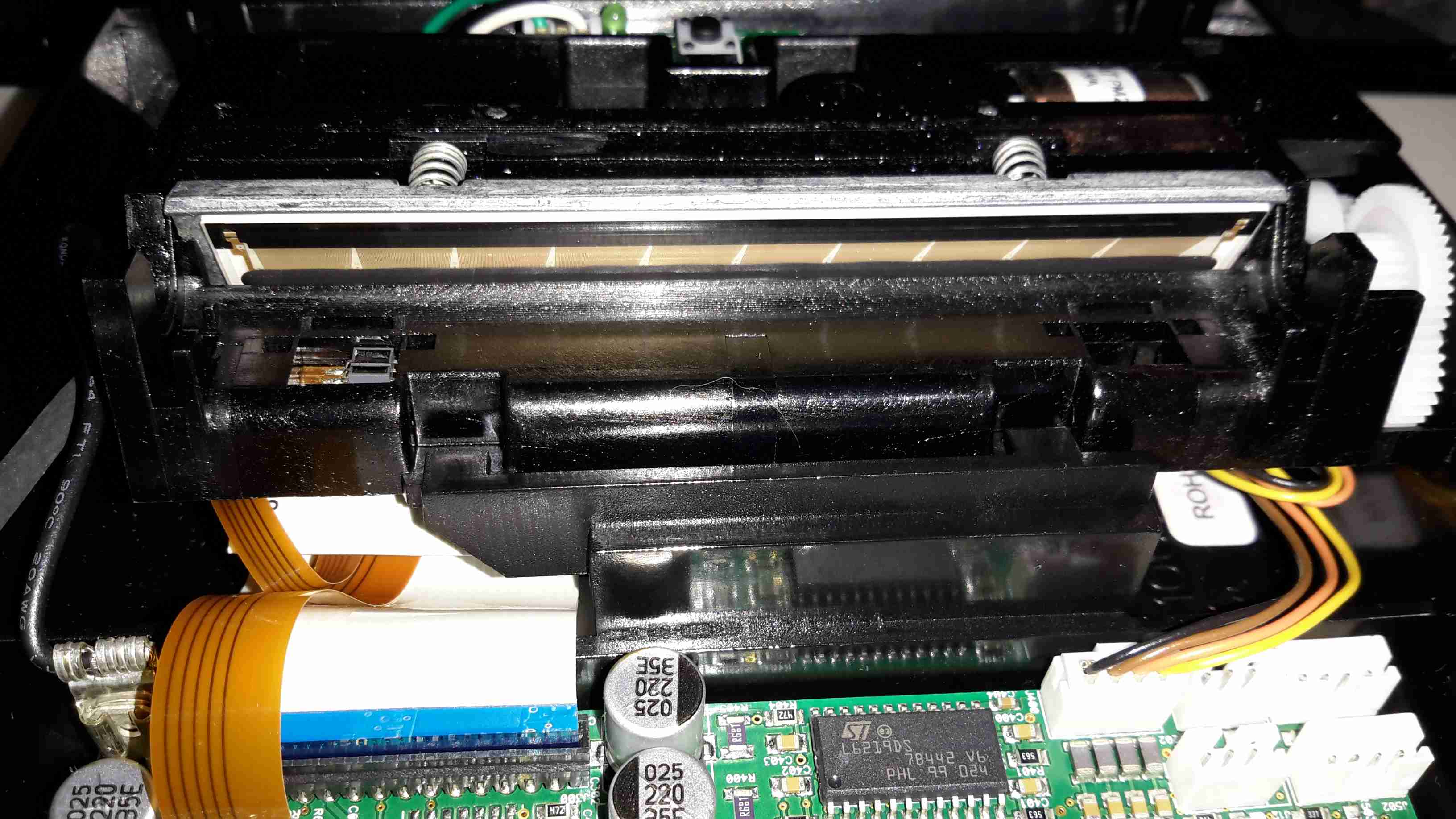
Print Head
Here’s the thermal mechanism itself, with the large print head. The stepper motor to drive the paper through the printer is just peeking out at top right. The paper present sensor is just under the left hand side of the print head.
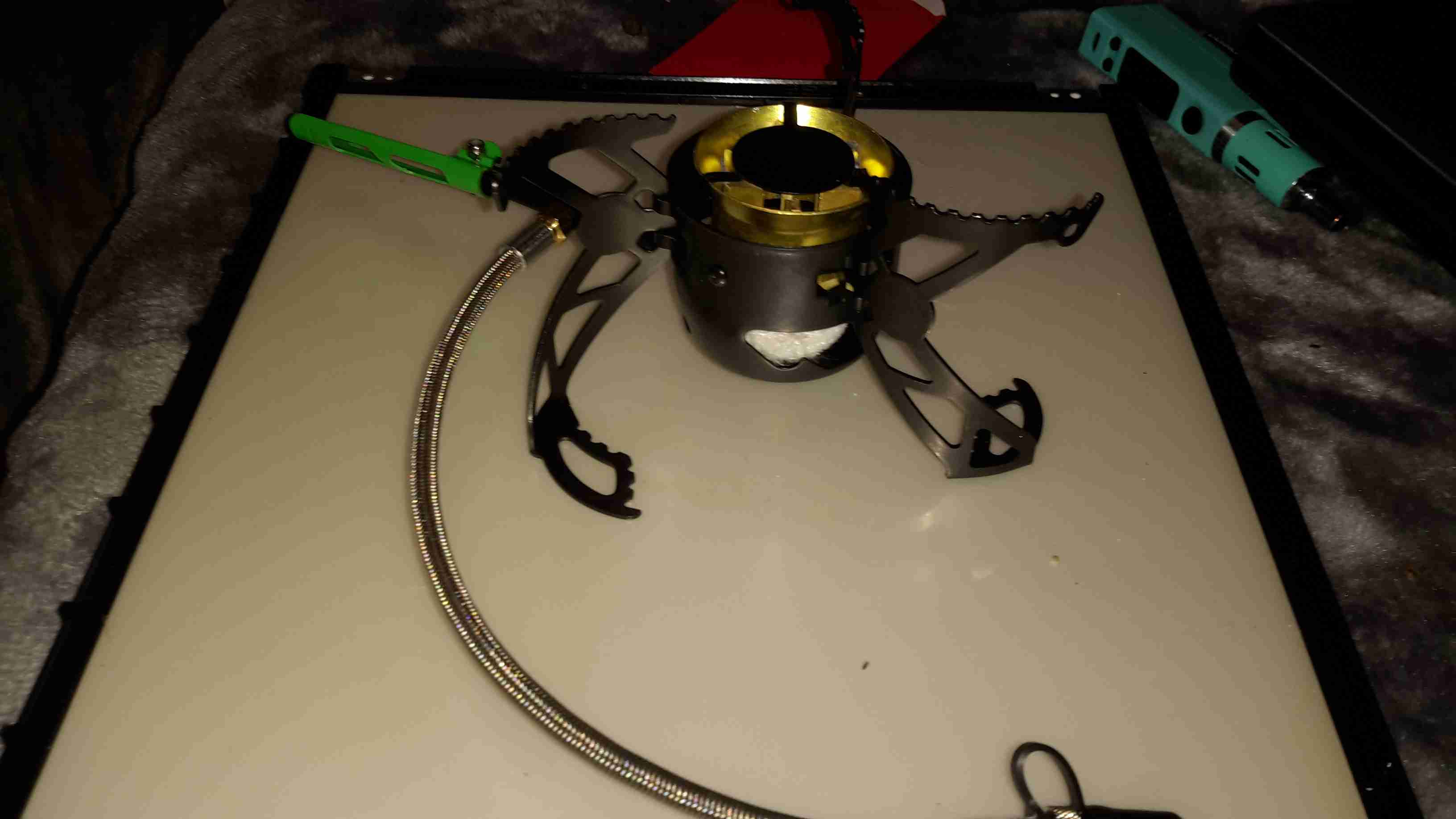
For as long as I can remember I’ve been using Trangia-type alcohol fuelled stoves when I go camping, even though these have served my needs well they’re very limited & tend to waste fuel. I did some looking around for Paraffin/Kerosene fuelled stoves instead, as I already have this fuel on site.
I found very good reviews on the Optimus Nova above, so I decided to go for this one.
This stove can run on many different fuel types, “white gas” (petrol without any vehicle additives) Diesel, Kerosene & Jet A.
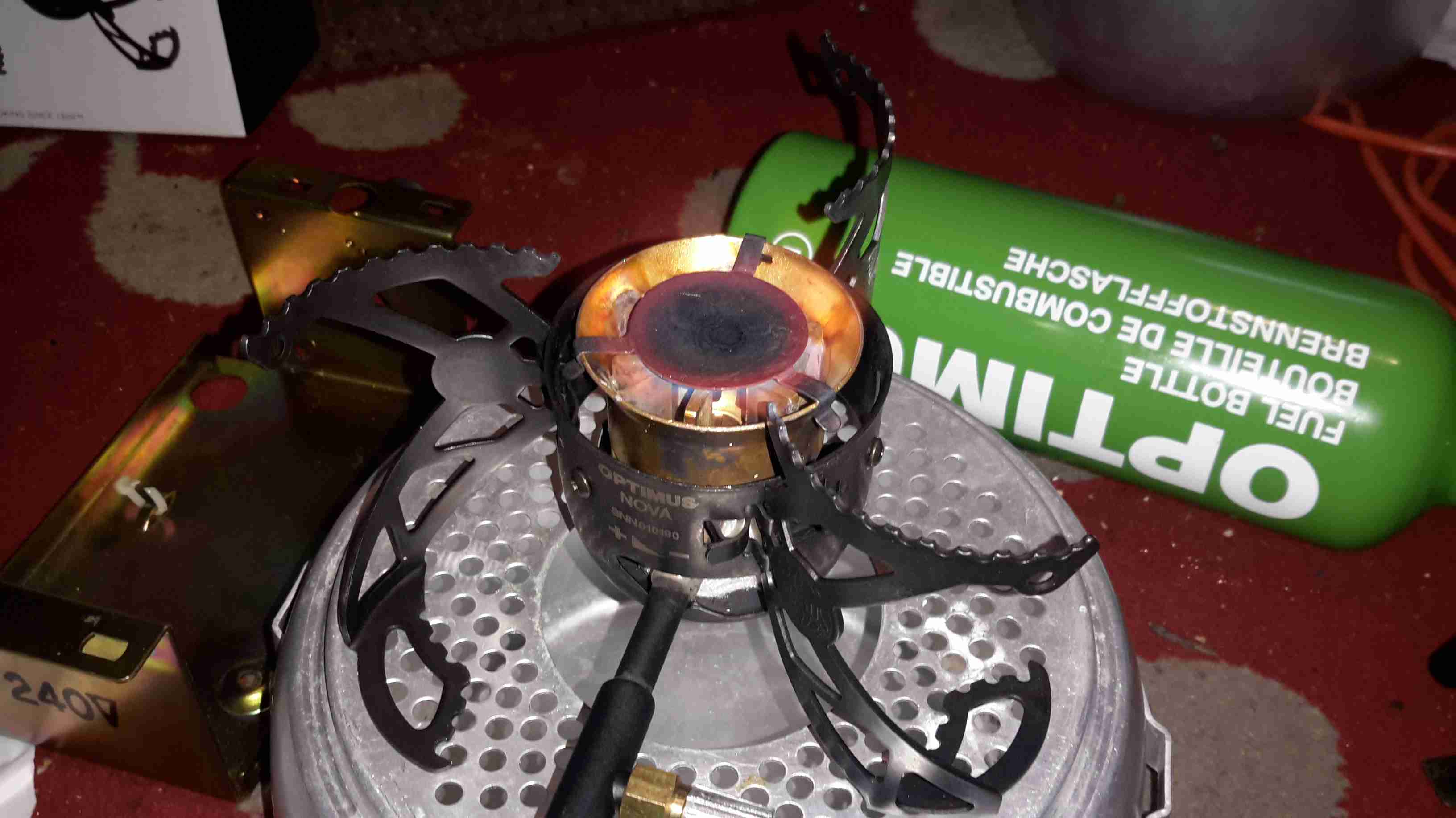
Burner
Here’s the “hot end” of the device, the burner itself. This is made in two cast Brass sections, that are brazed together. The fuel jet can be just seen in the centre of the casting.
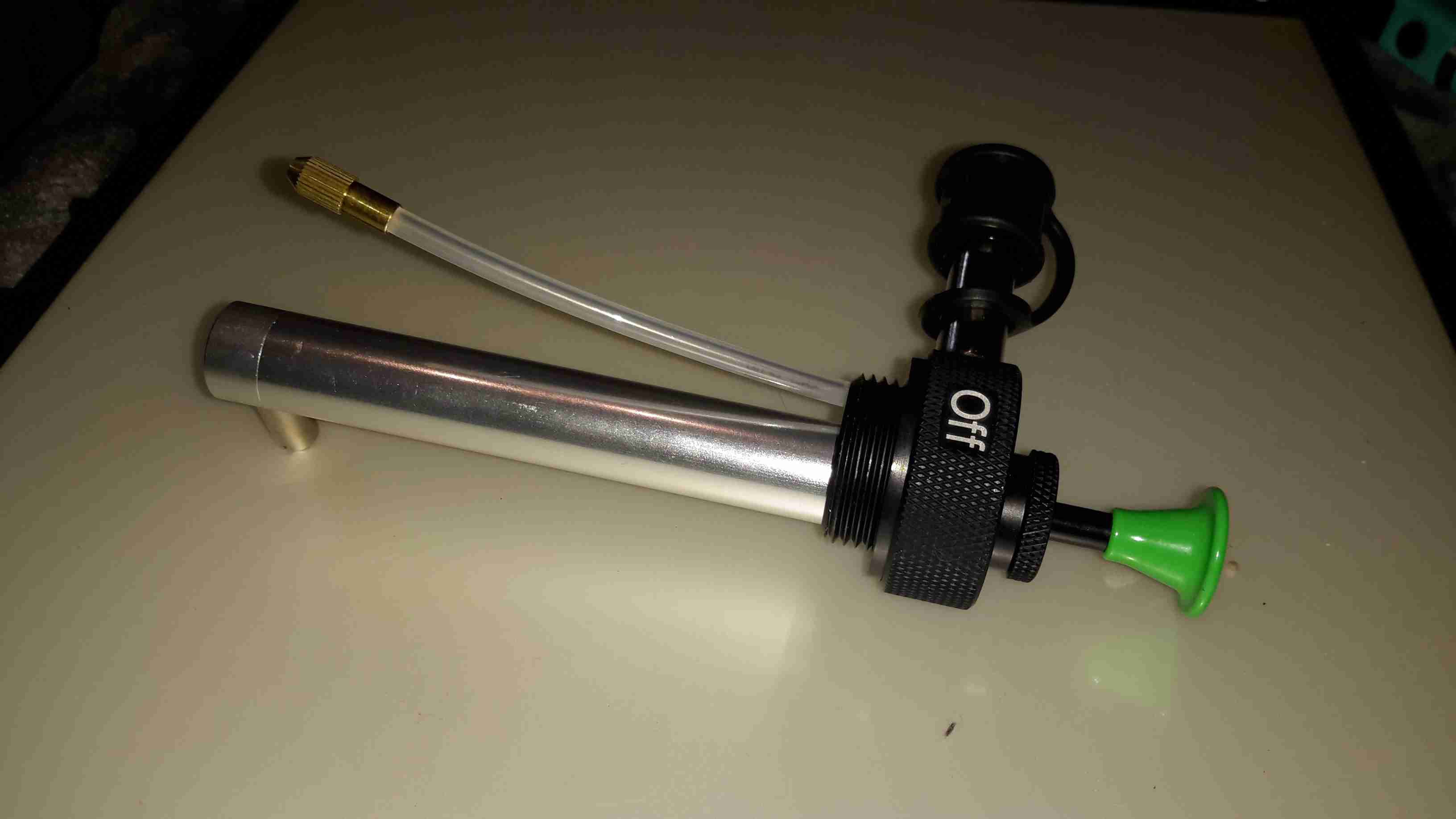
Fuel Pump
The fuel bottle is pressurised with a pump very similar to the ones used on Paraffin pressure lamps, so I’m used to this kind of setup. The fuel dip tube has a filter on the end to stop any munge gumming up the valves or the burner jet.
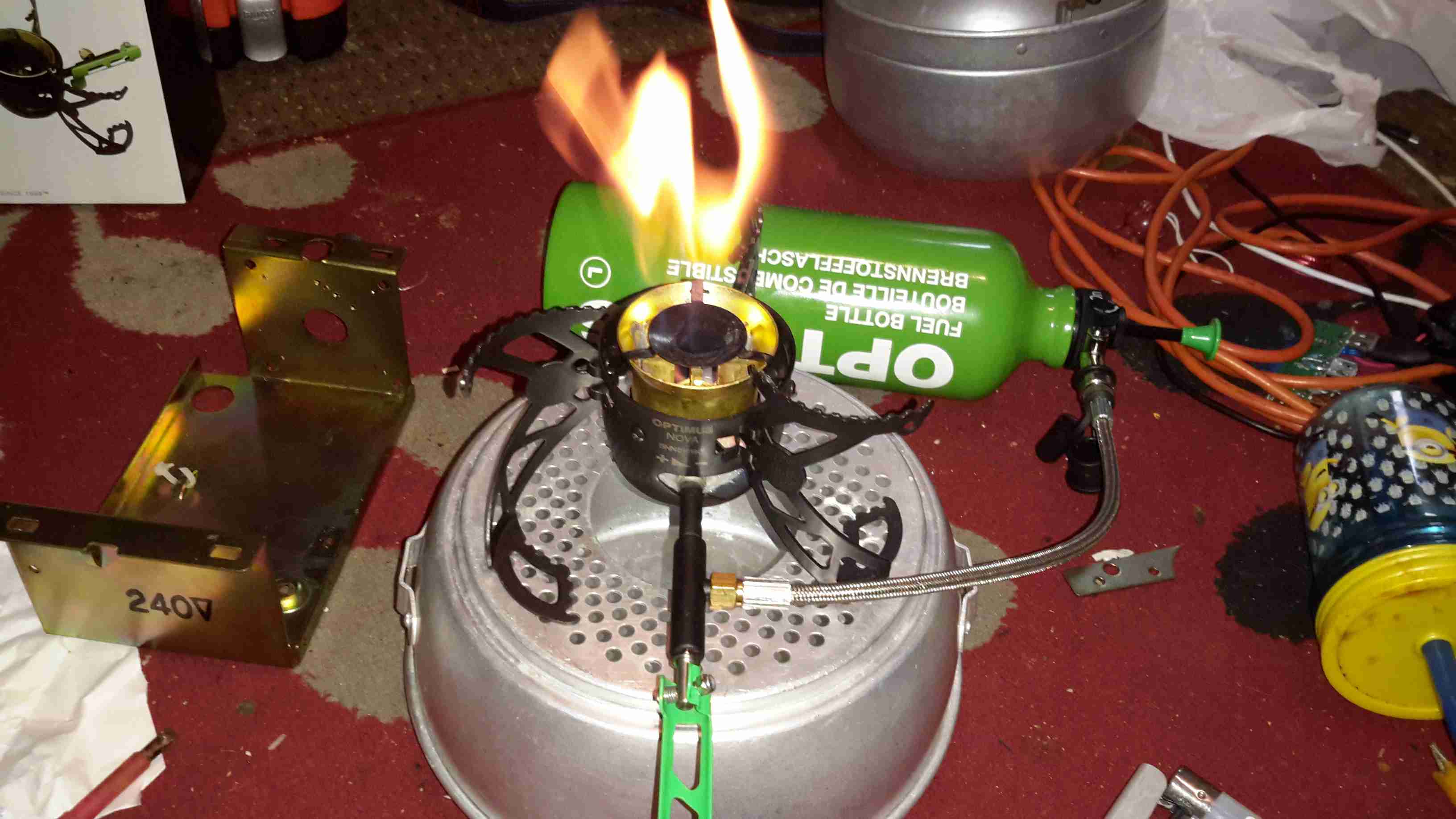
Pre-Heating
As with all liquid-fuelled vapour burners, it has to be preheated. There’s a fibreglass pad in the bottom of the burner for this, and can be soaked with any fuel of choice. The manual states to preheat with the fuel in the bottle, but as I’m using Paraffin, this would be very smoky indeed, so here it’s being preheated with a bit of Isopropanol.
The fuel bottle can be seen in the background as well, connected to the burner with a flexible hose. The main burner control valve is attached to the green handle bottom centre.
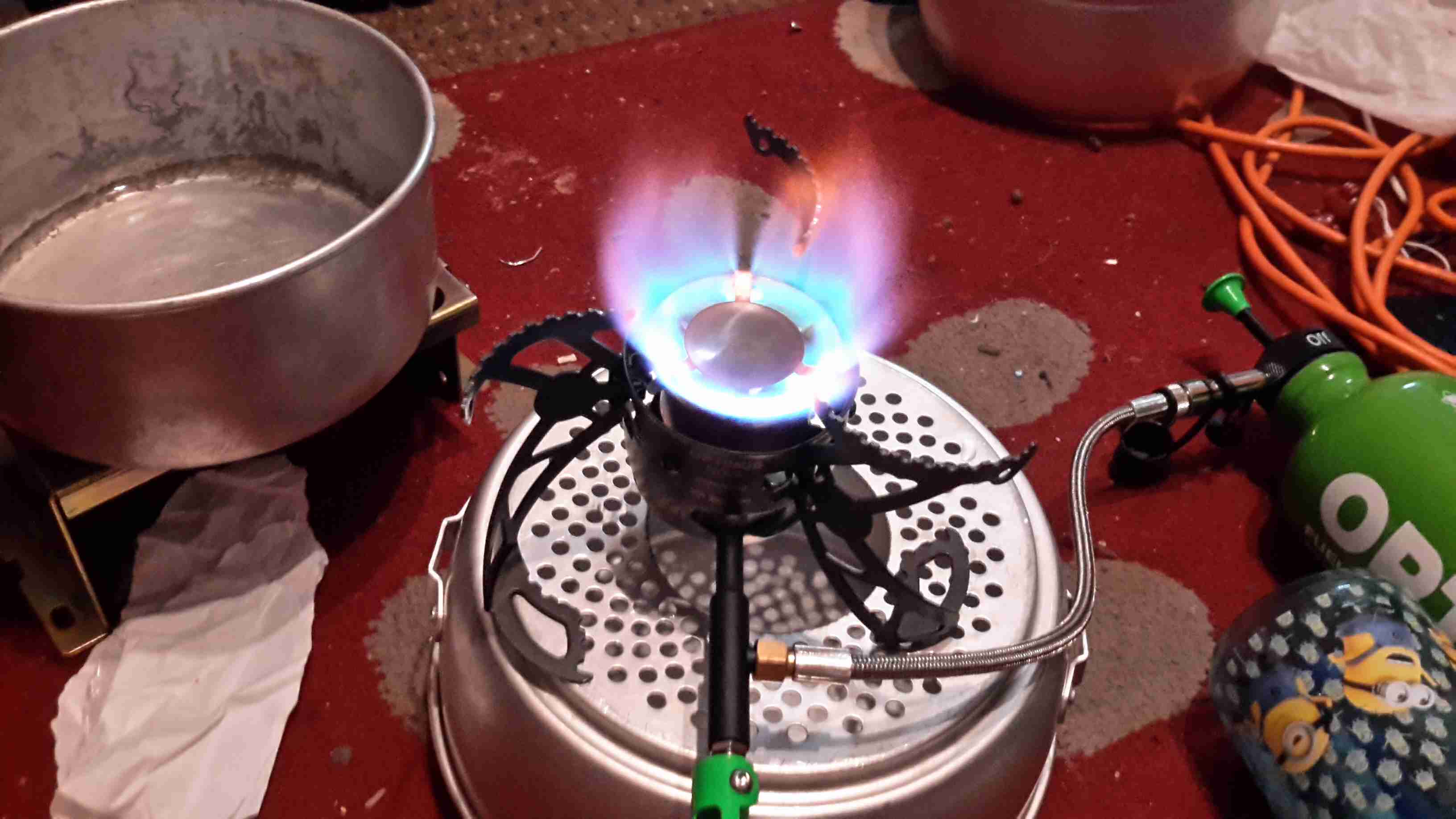
Simmer
Once the preheating flame has burned down, the fuel valve can be opened, here’s the stove burning Paraffin on very low simmer. (An advantage over the older alcohol burners I’m used to – adjustable heat!)
Full Power!
Opening the control valve a couple of turns gives flamethrower mode. At full power, the burner is a little loud, but no louder than my usual Paraffin pressure lamps.
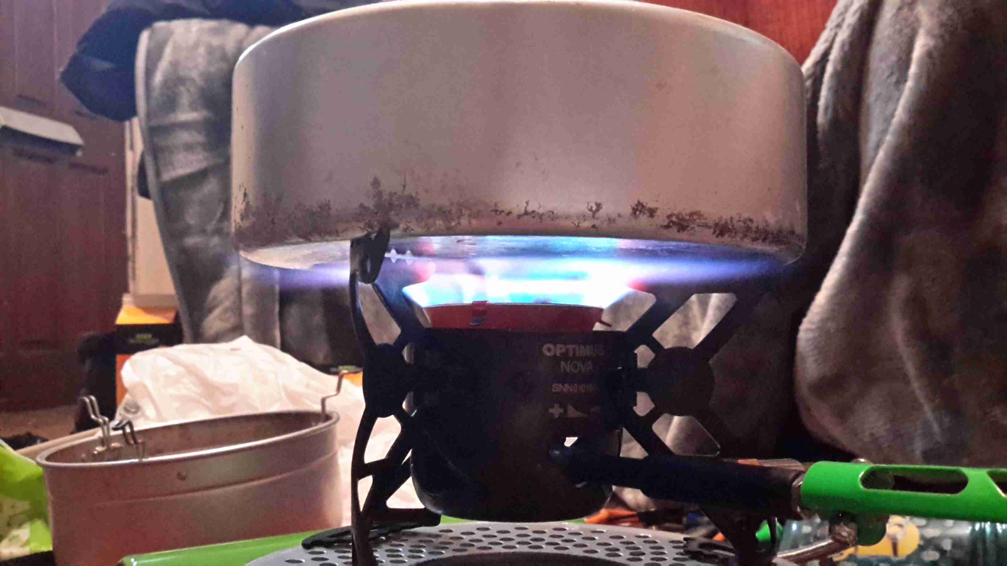
Flame Pattern
With a pan of water on the stove, the flame covers the entire base of the pan. Good for heat transfer. This stove was able to boil 1L of water from cold in 5 minutes. A little longer than the manual states, but that’s still much quicker than I’m used to!
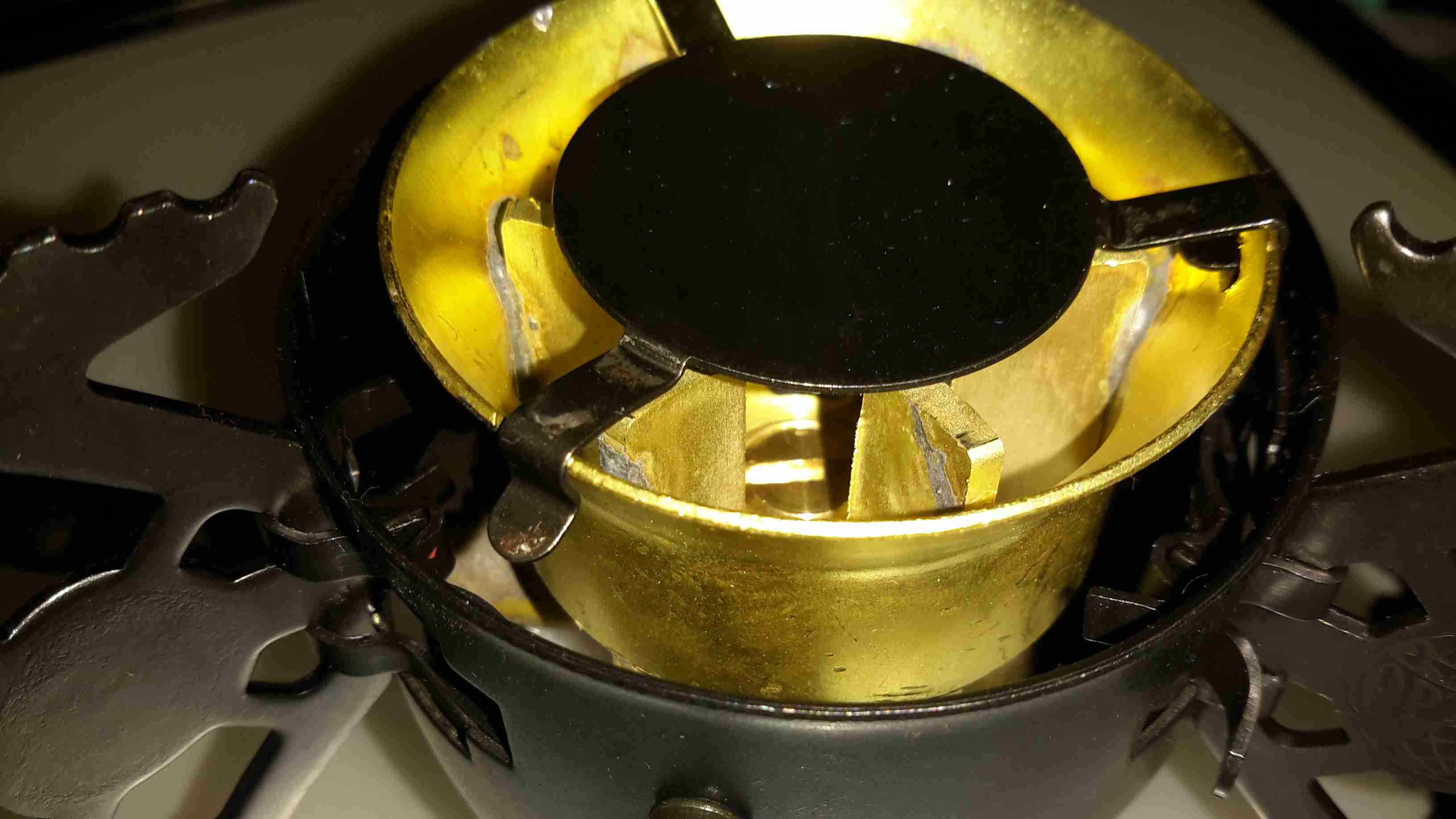
Fuel Jet
The top of the burner opens for cleaning, here’s a look at the jet in the centre of the burner. The preheating pad can be seen below the brass casting.
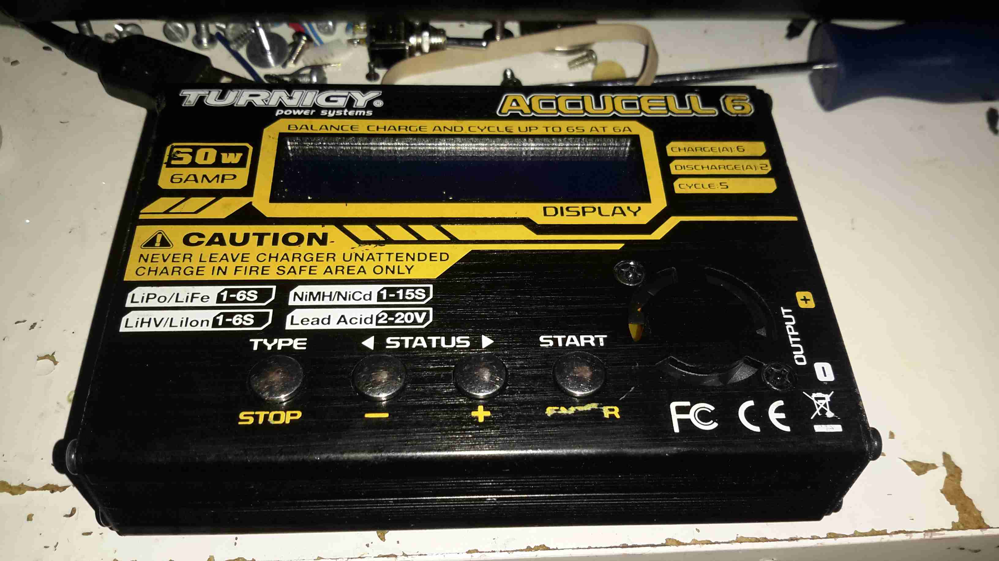
A lot of the electronics I use & projects I construct use batteries, mainly of the lithium variety. As charging this chemistry can be a little explosive if not done correctly, I decided a proper charger was required. This charger is capable of handling packs up to 6 cells for Lithium, and up to 20v for lead-acids.
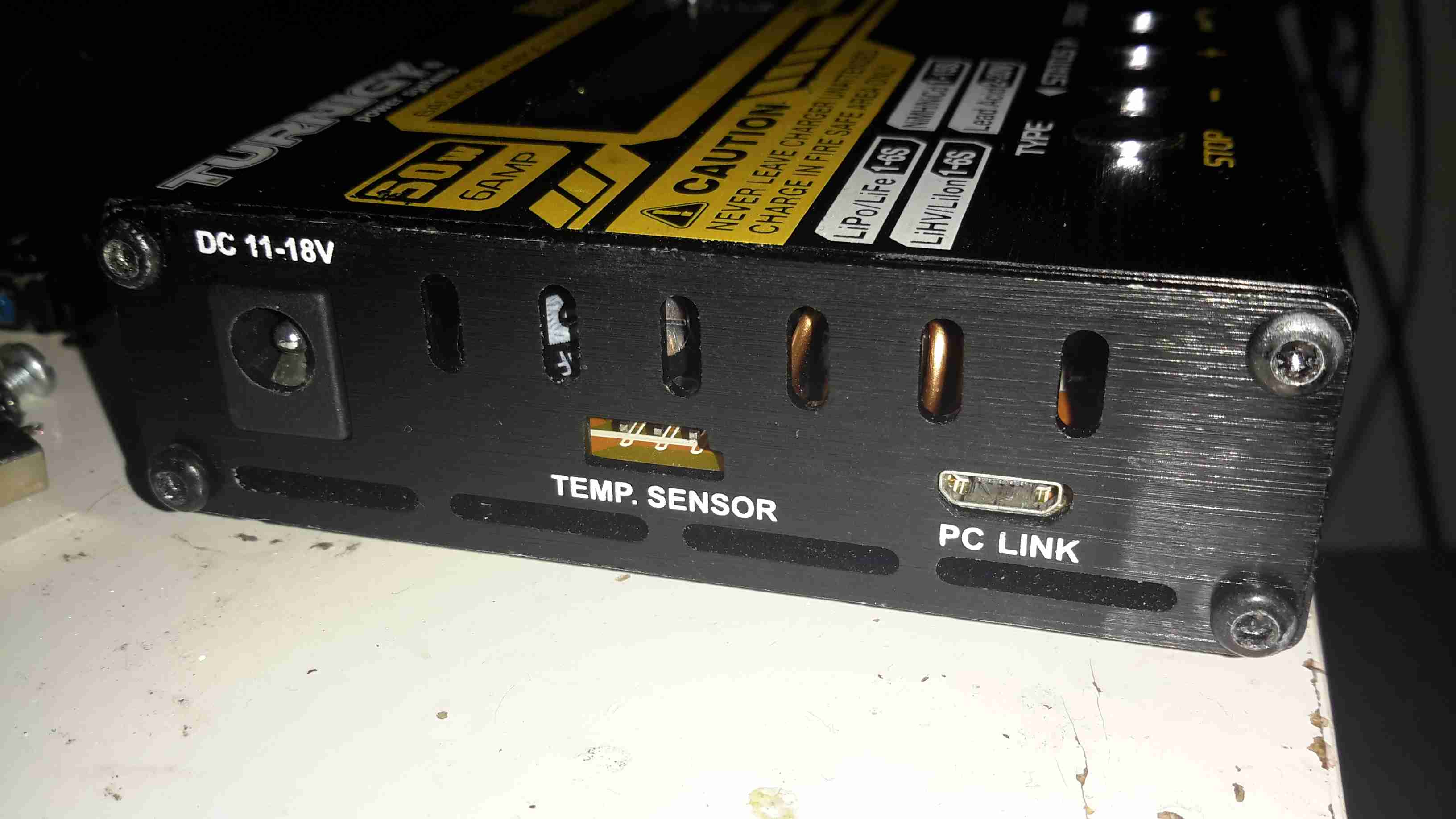
External Connections
The usual DC input barrel jack on the left, with an external temp sensor for fast charging NiCd/NiMH chemistry batteries. The µUSB port registers under Linux as USB HID, probably so drivers aren’t required. Unfortunately the software is Windows only, but it doesn’t provide anything handy like charging graphs or stats. Just a way to alter settings & control charging from a PC. On other versions of this charger there’s a setting to change the temp sensor port into a TTL serial output, which would be much handier.
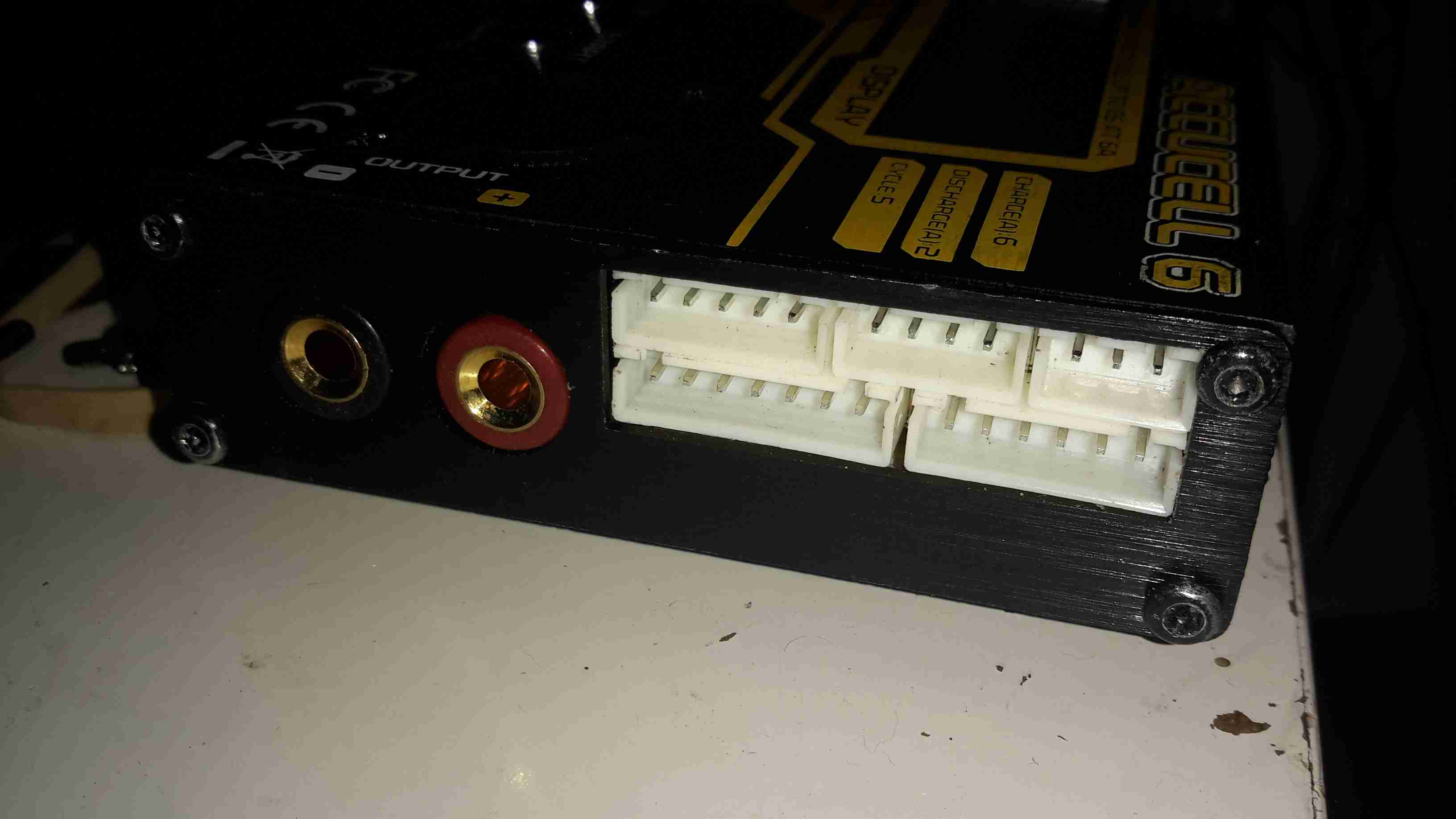
Output & Balance
The other side of the charger has the main DC output jacks & the pack balancing connections.
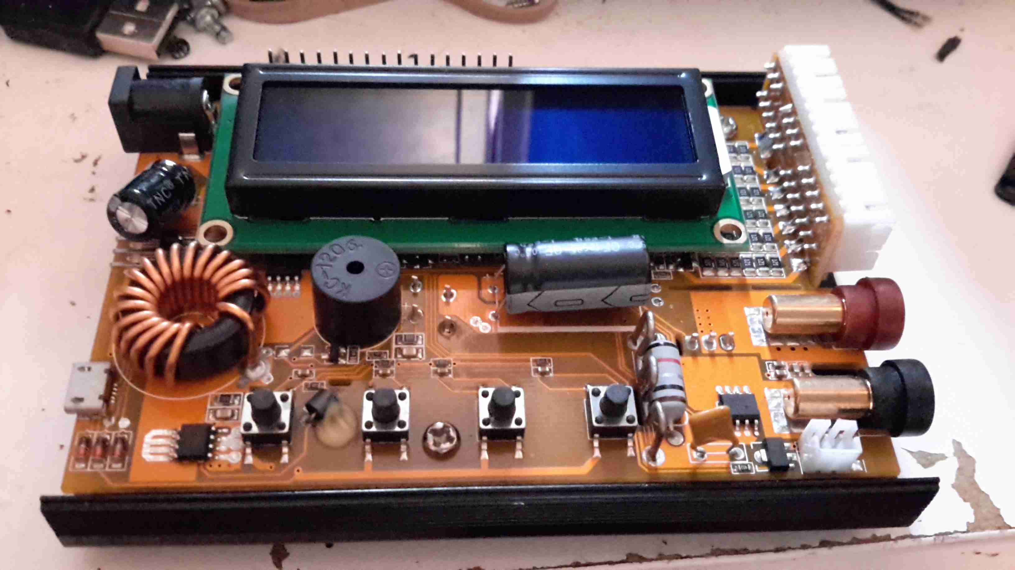
Cover Removed
Here’s the top cover removed from the charger, showing most of the internals. A standard HD44780 LCD provides the user interface, the CPU & it’s associated logic is hidden under there somewhere.
The PCB has nice heavy tracks to handle the 6A of current this charger is capable of.
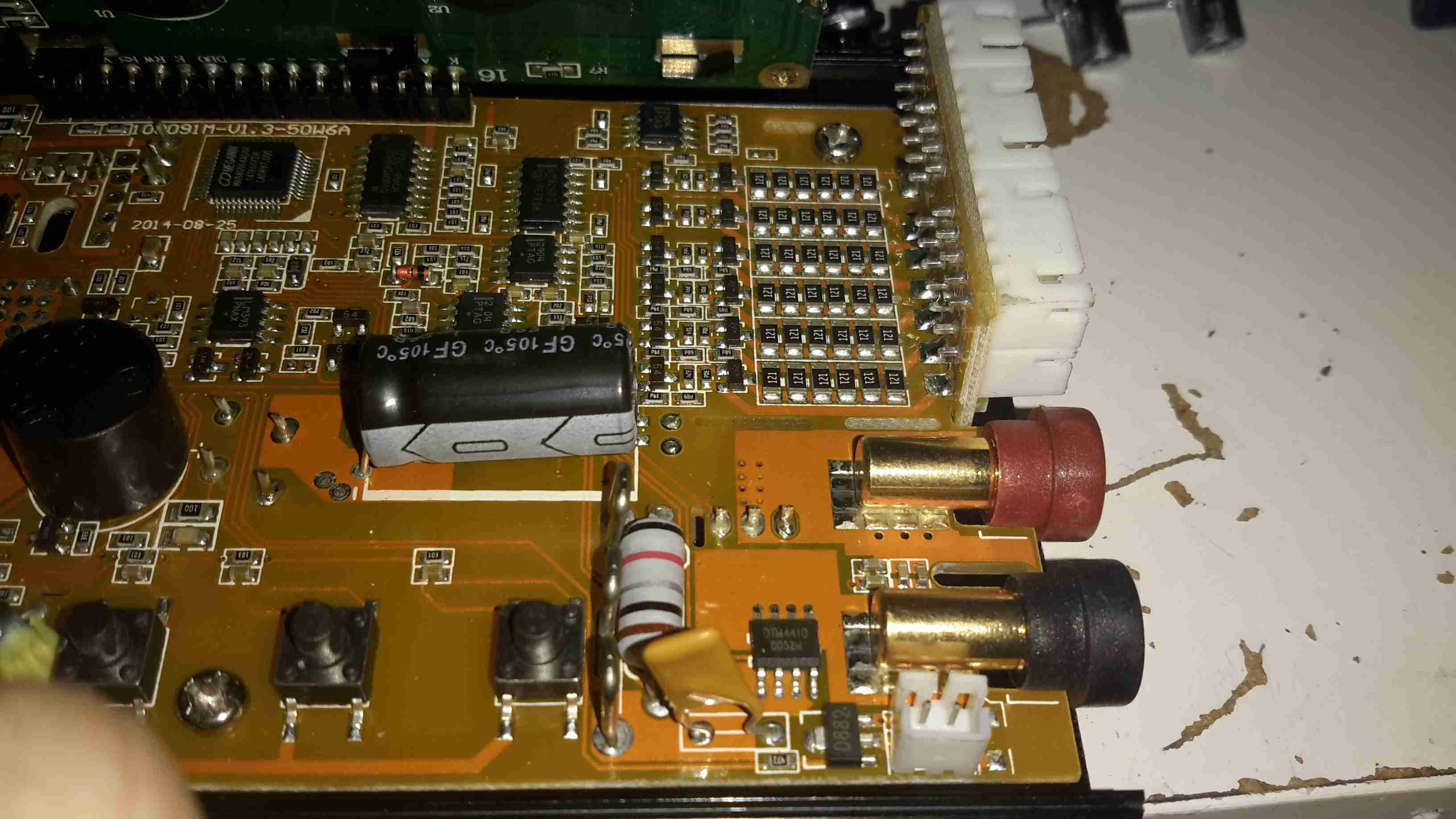
Balancing Network
The output side of the board. Here the resistive pack balancing network can be seen behind the vertical daughter board holding the connectors, along with the output current shunt between the DC output banana jacks & the last tactile button.
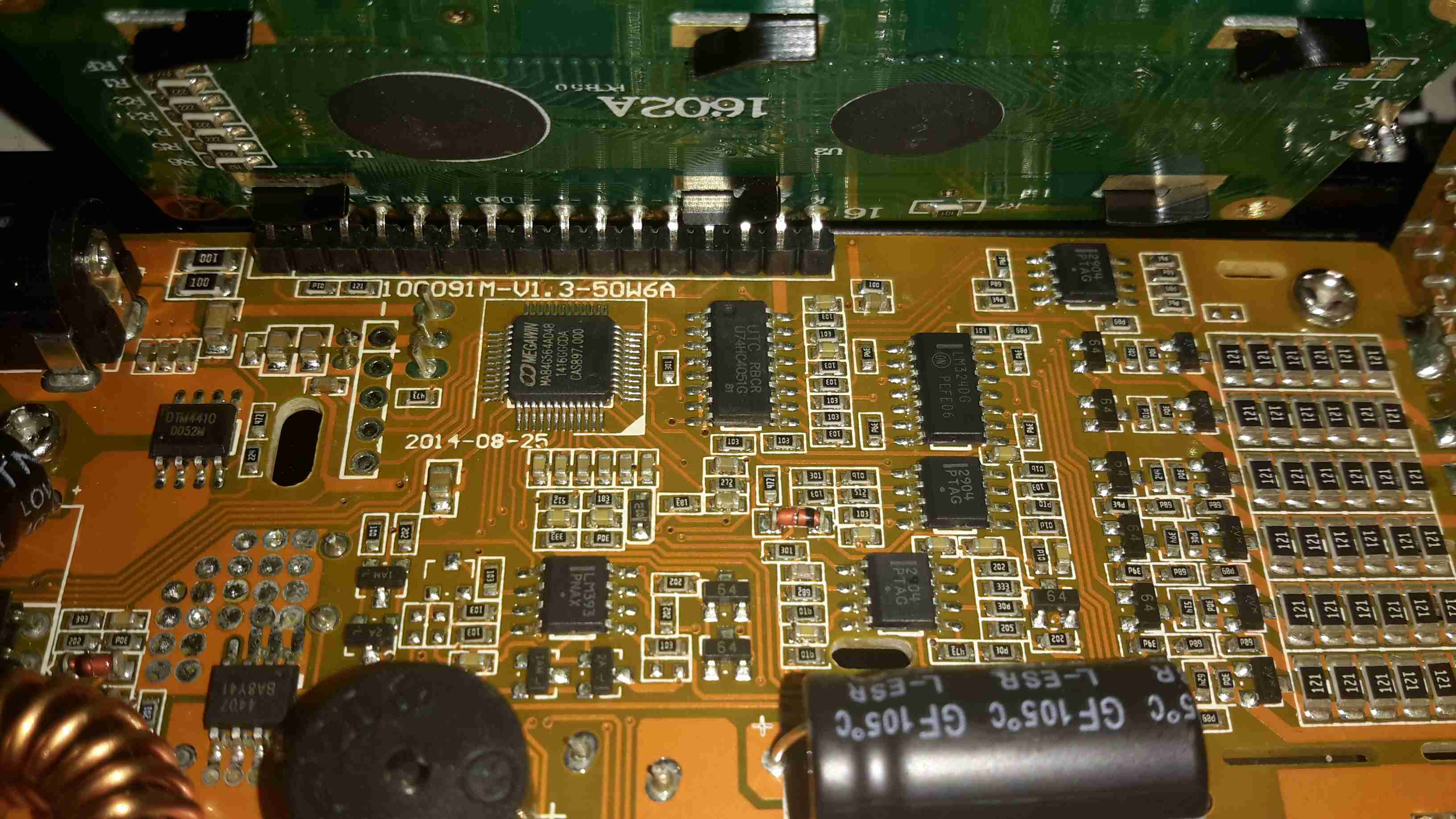
Main Logic
Unfortunately the LCD is soldered directly to the board, and my desoldering tool couldn’t quite get all the solder out, so time to get a bit violent. I’ve gently bent the header so I could see the brains of the charger. The main CPU is a Megwin MA84G564AD48, which is an Intel 8081 clone with USB support. Unfortunately I was unable to find a datasheet for this part, and the page on Megwin’s site is Chinese only.
I was hoping it was an ATMega328, as I have seen in other versions of this charger, as there are custom firmwares available to increase the feature set of the charger, but no dice on this one. I do think the µUSB port is unique to this version though, so avoiding models with that port probably would get a hackable version.
There’s some glue logic for controlling the resistor taps on the balancing network, and a few op-amps for voltage & current readings.
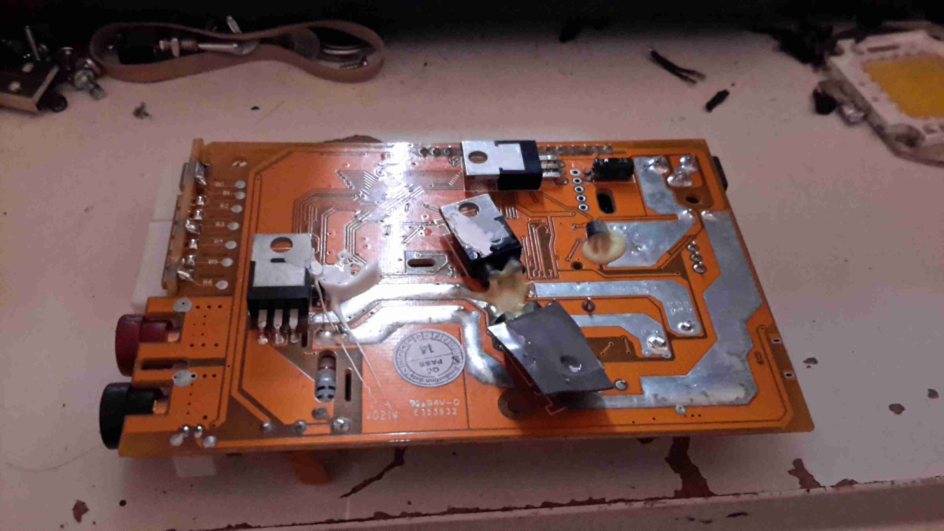
Power Switching Devices
All the power diodes & switching FETs for the DC-DC converter are mounted on the bottom of the PCB, and clamped against the aluminium casing when the PCB is screwed down. Not the best way to ensure great contact, but Chinese tech, so m’eh.
It’s well known that there are two versions of the 701 type controller available for Eberspacher heaters, the version with the blue logo is the official un-restricted model, while the version with the white logo is a version built for BT that restricts the heater to 1 hour runtime & has no diagnostics built in.
As these devices are microcontroller driven, I assumed that the hardware would be the same, only the code running in the micro being the bit that Eberspacher changed. This option would certainly have been the lowest cost.
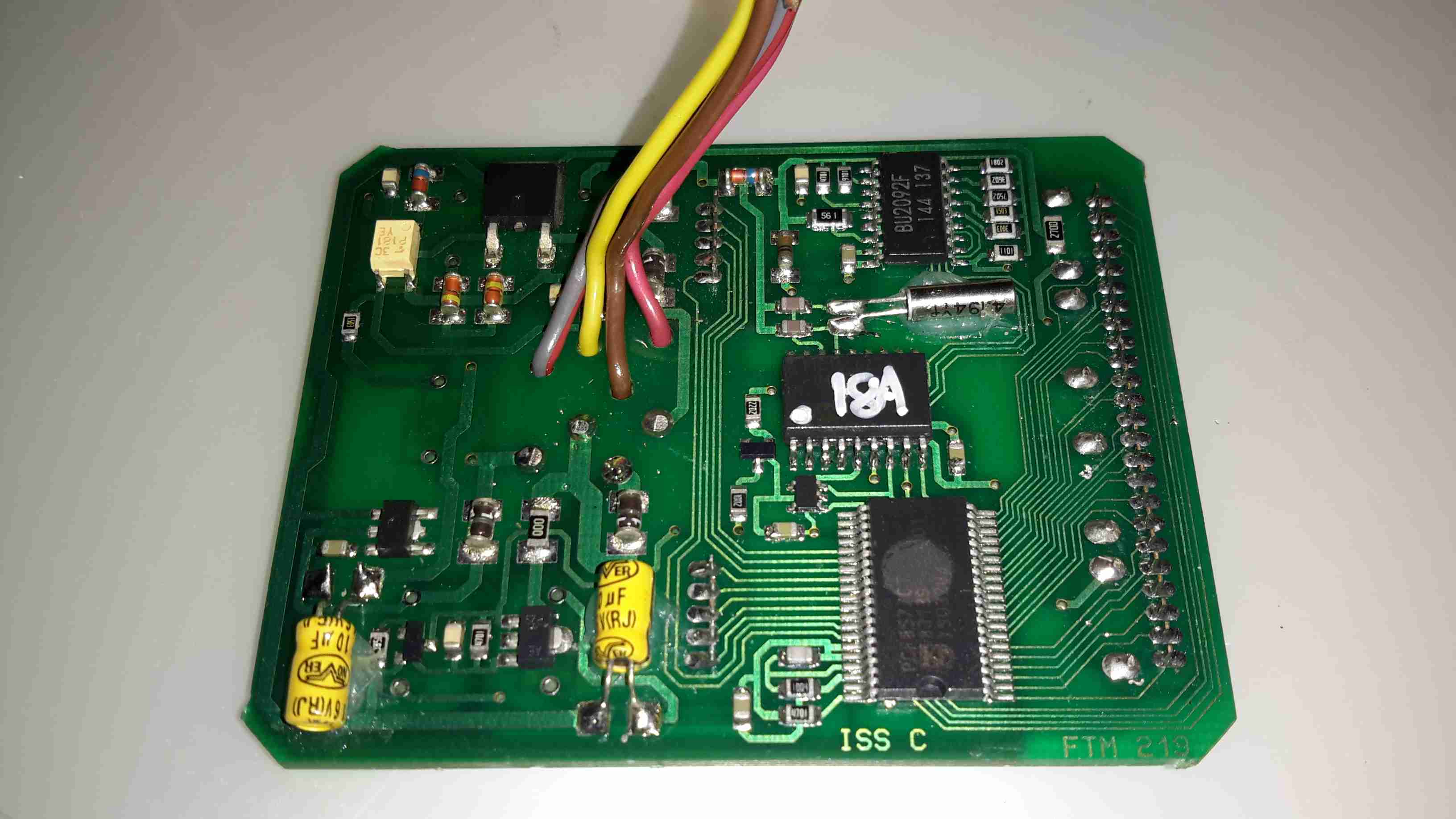
Controller PCB Rear
Here’s the PCB removed from the plastic housing. There are definitely some differences that I can tell. As the un-restricted version has an extra wire for the diagnostic serial interface, and this board has no unpopulated parts, the PCB is definitely a different version.
In the centre is a Microchip PIC16C622 microcontroller, the OTP version in this case for cost reductions. (I may try reading the binary from this chip in the future, chances are it’s code protected though).
Below the micro is an NXP PCF8577C 32-segment LCD controller, this has an I²C interface to the PIC.
The temperature control function on these heaters is done via applying a resistance to one of the control lines, between 1750Ω-2180Ω, ±80Ω. (Very odd values these, not to mention no standard components can create this range easily, bloody engineers >_<). This is accomplished in hardware with a BU2092F I²C shift register from Rohm, which is connected to a bank of resistors. The microcontroller will switch combinations of these into the circuit to get the range of resistances required.
The rest of the circuit is local power regulation & filtering.
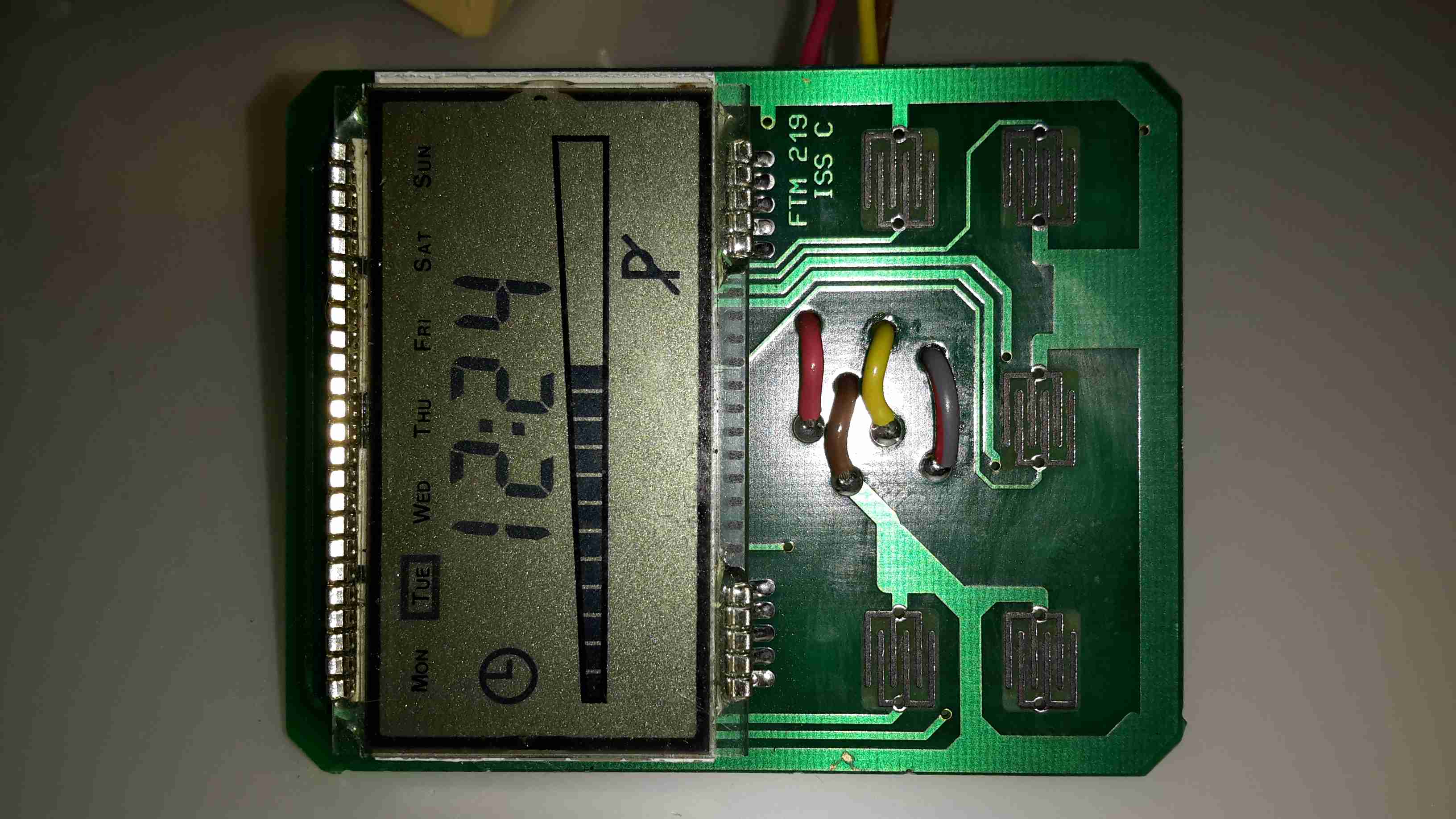
Controller PCB Front
There’s not much on the other side of the PCB, just the LCD itself & the contacts for the buttons.
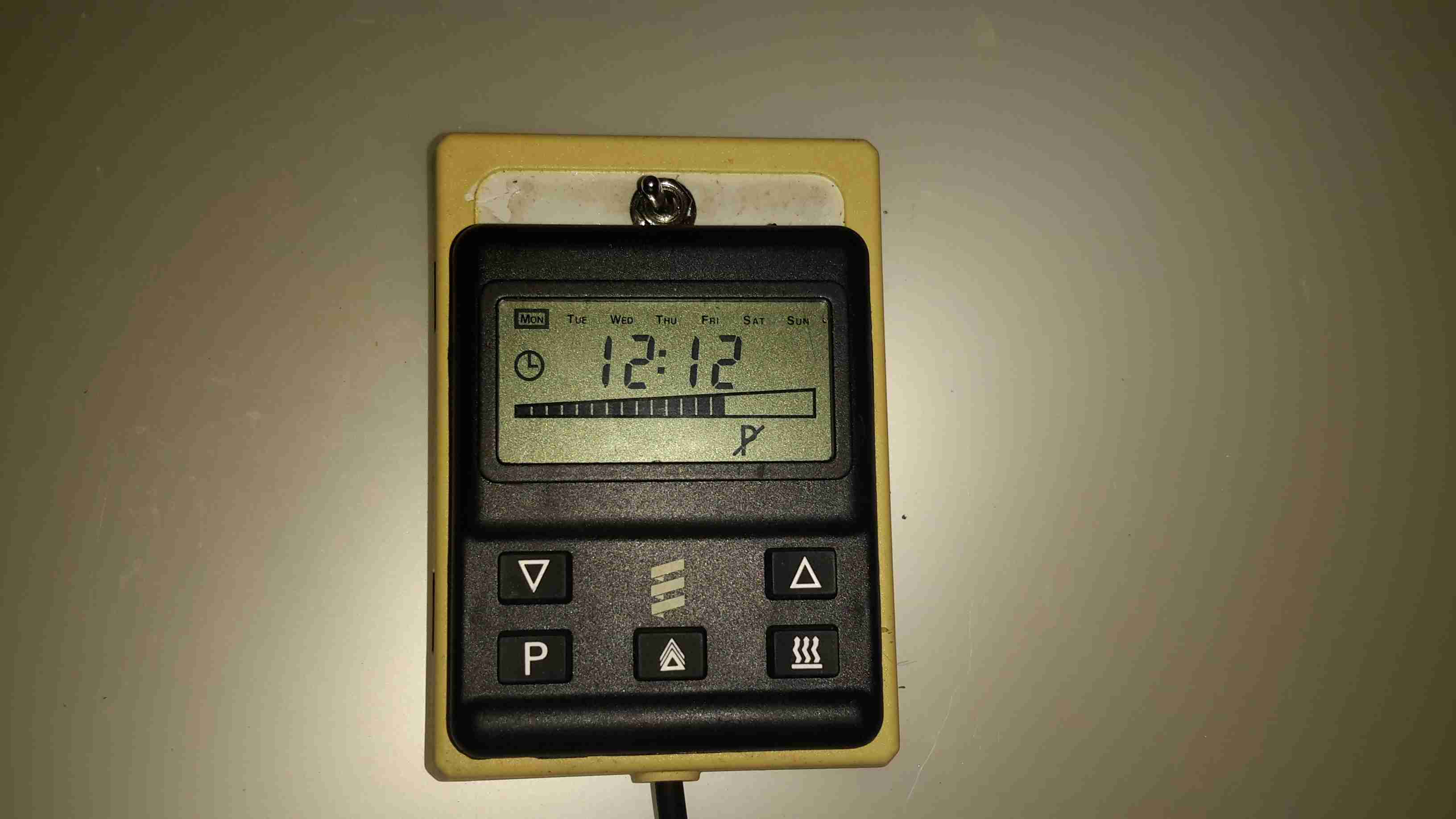
The Eberspacher heaters can be controlled with a single switch, but it’s more convenient to have some temperature control & the option of a timer. Above is an ex-BT 701 series controller, with built in 7-day programmer. Being an ex-BT van version though, it’ll only switch the heater on for 1 hour at a time.
To get around this slight niggle, I fitted a bypass toggle switch.
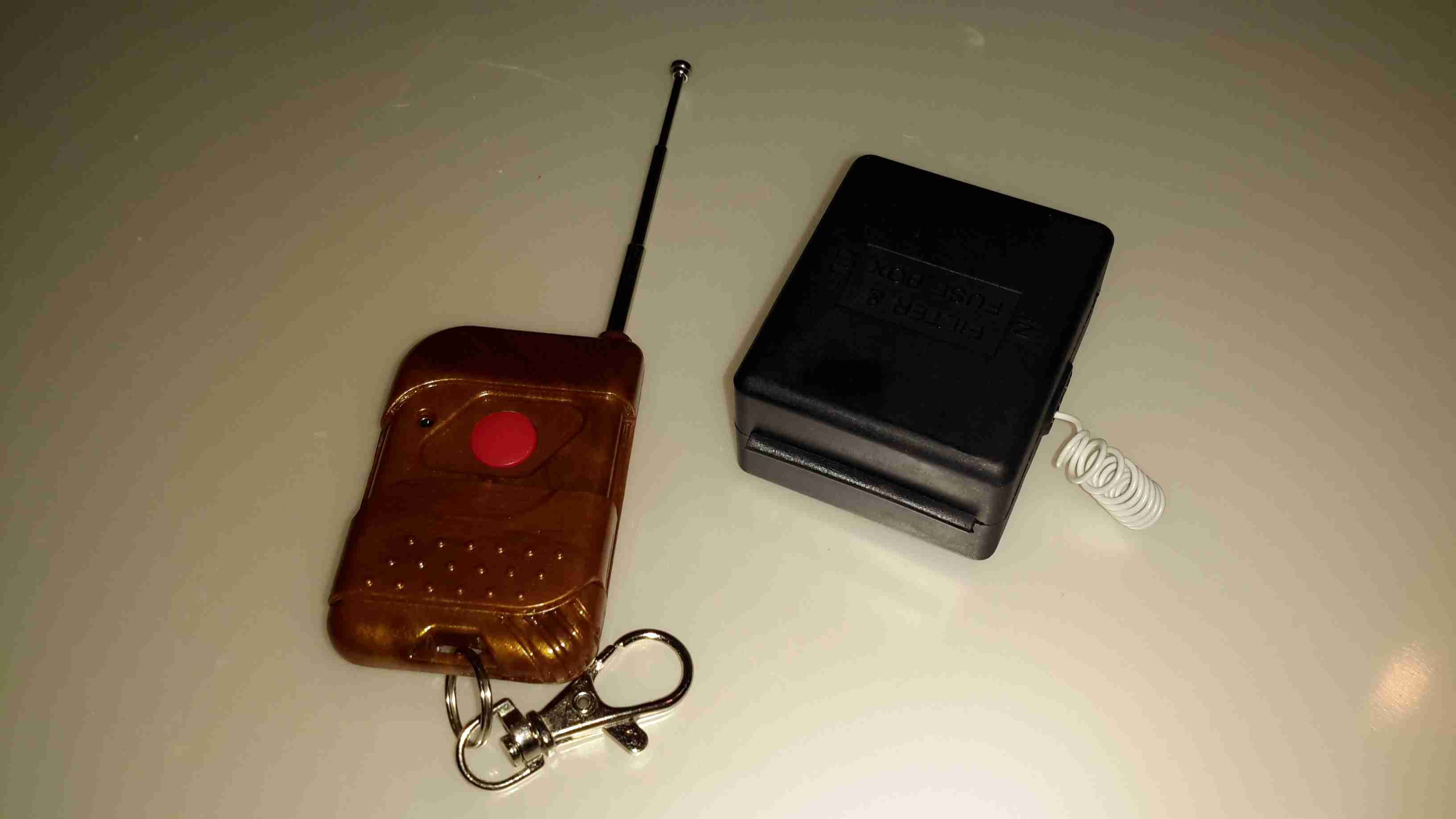
Remote Control
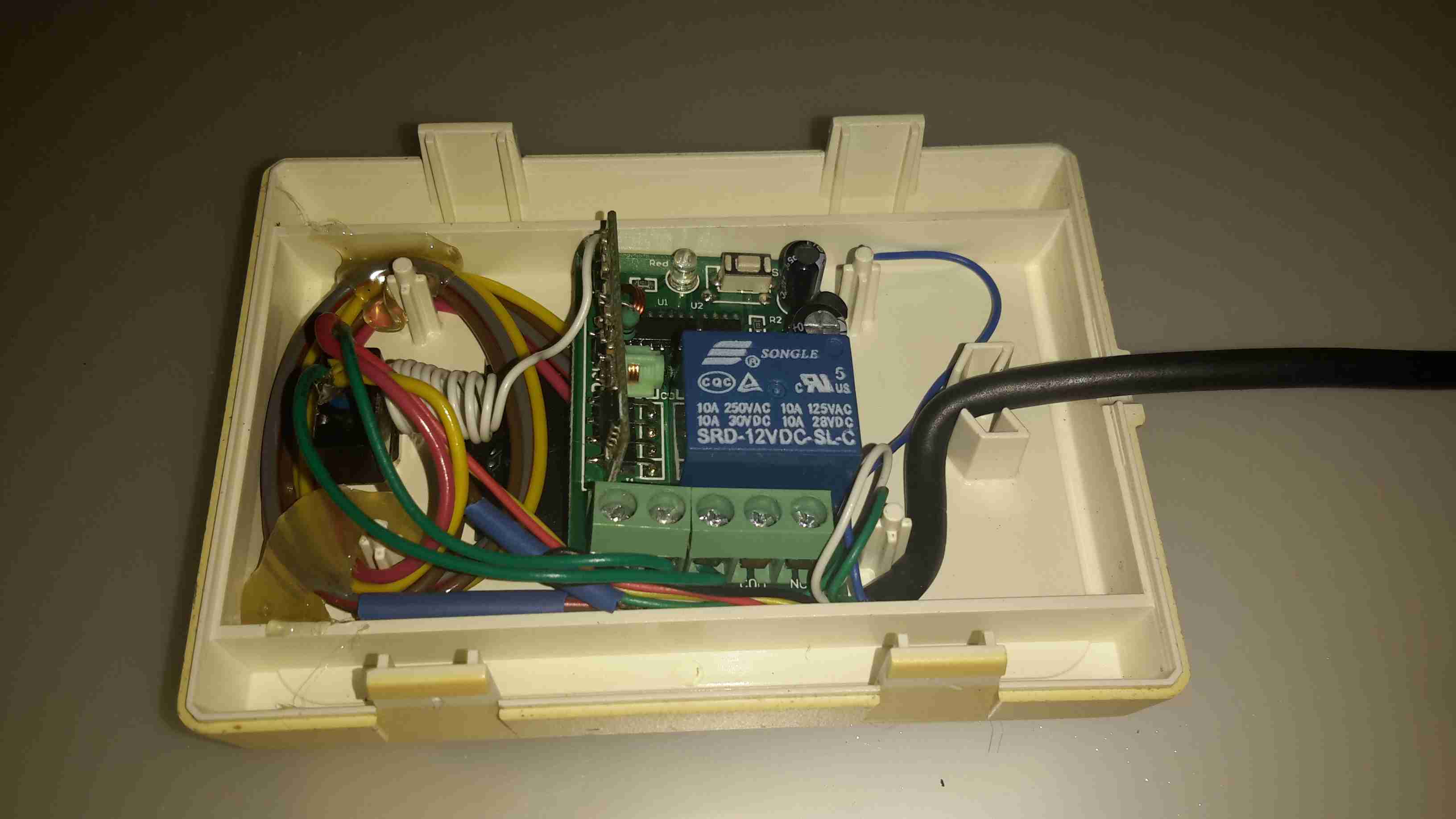
For a bit of extra convenience, I got an RF remote controlled relay module from eBay (£5).
This allows me to switch things on remotely, so I can return to a nice toasty tent while camping.
There is an official RF remote for Eberspacher heaters, but I’ve no doubt they’re hideously expensive.
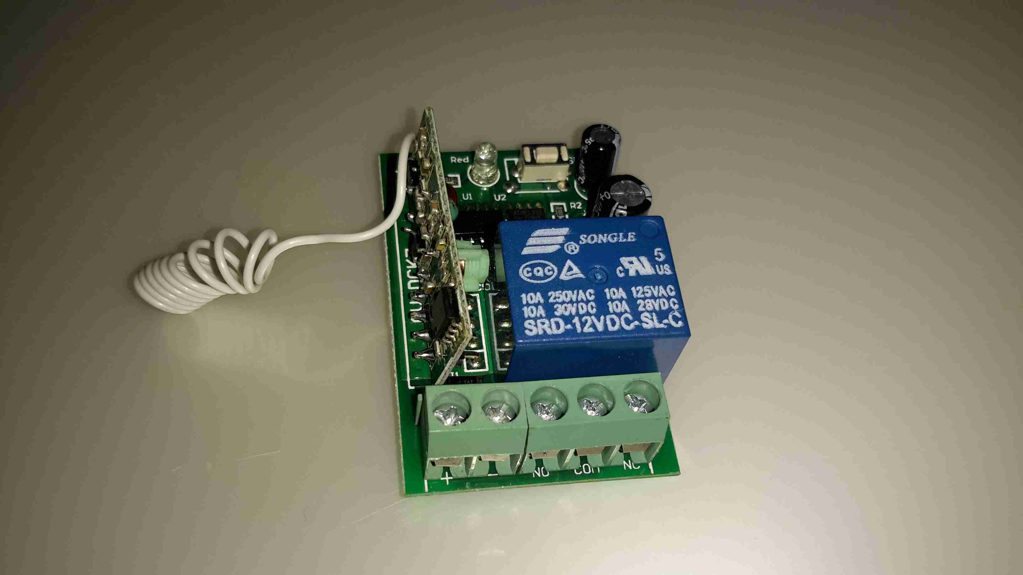
RF Receiver
Here’s the receiver PCB, there’s an EEPROM & a microcontroller onboard for handling the codes the remotes send, but as the number has been scrubbed off the micro, no data there. This uses a standard RF receiver module.
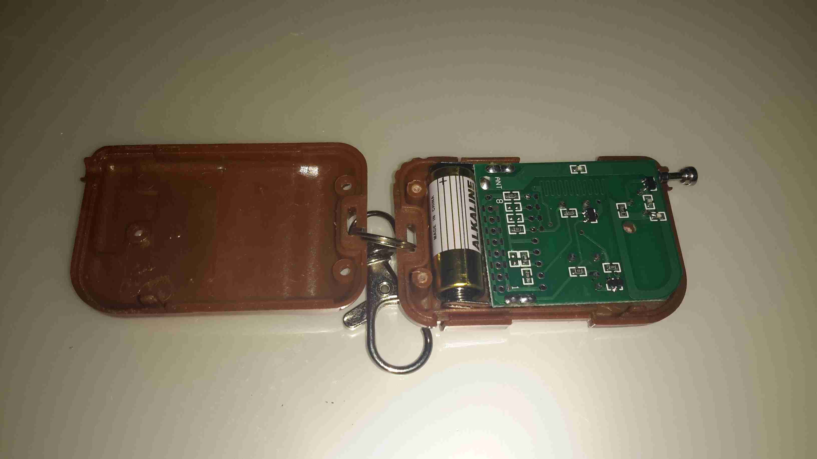
RF Remote
Here’s the remote itself, this uses a 12v battery instead of a 3v lithium cell. A little of a pain since these batteries can be a bit pricey.
As this RF system operates on 315MHz, it’s technically illegal in the UK, but I was unable to find a 433MHz version with the features required. Nevermind ;).
Controller Internals
Here’s the module installed in the controller casing. I have since run the antenna wire around the edge of the case to try & get the furthest range on receive. The relay contacts are just paralleled across the bypass switch, so when the relay energizes the heater fires up.
Luckily the thermostatic control portion of the 701 programmer is operational even when heating mode is not active.
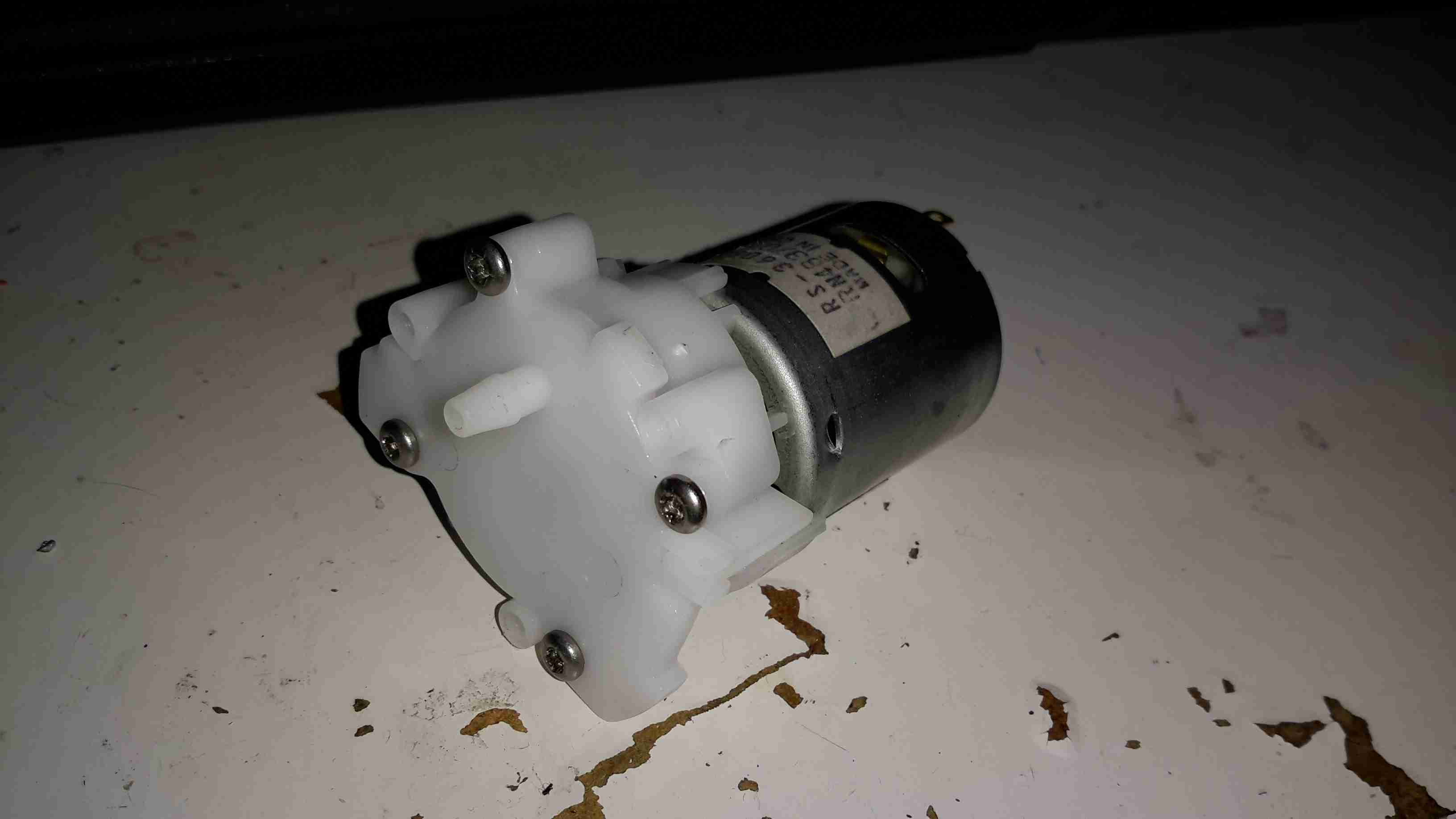
I got one of these to test since I’ve been in need of some small DC pumps for fluid transfer use. At £2 I can definitely afford to experiment.
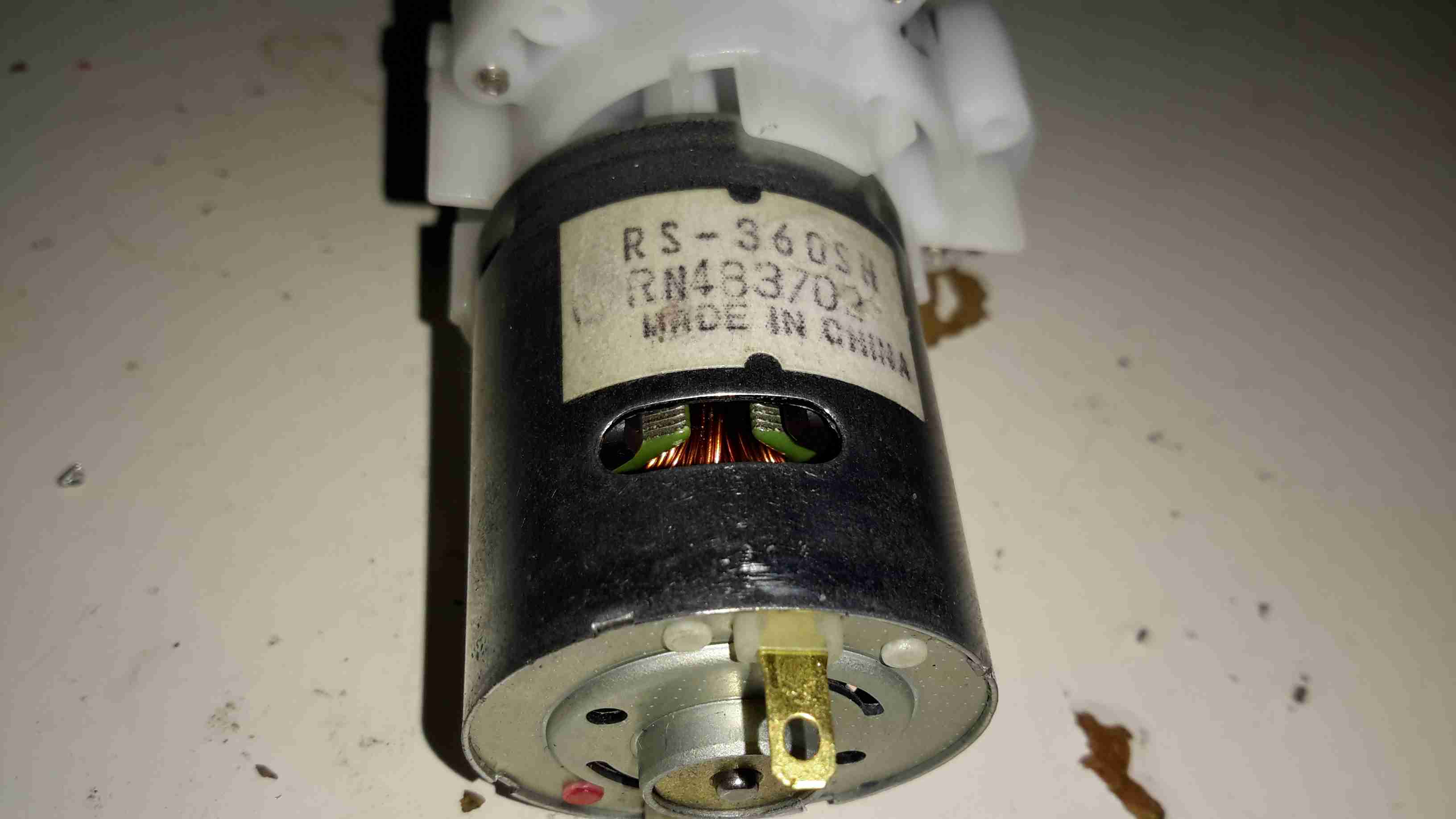
DC Motor
On the eBay listing, these pumps are rated at 3-12v DC, (I thought that was a bit wide of an operating range), I looked up the motor, an RS-360SH on Mabuchi’s website, they only have models in this range rated at 7.2v & 24v. Judging by the size of the windings on the armature & the fact that after a few minutes operation on 12v it gets rather hot, I’m going to say this is the 7.2v motor.
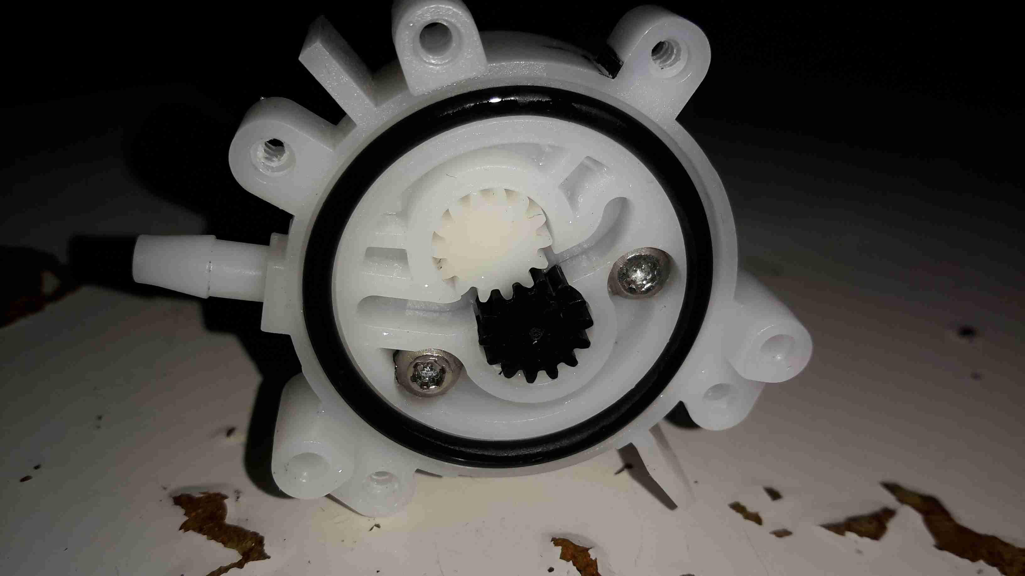
Pump Gears
Removing the screws releases the end cover & the pair of gears inside. This operates like any other hydraulic gear motor, albeit with much wider tolerances. It has no capability to hold pressure when the power is removed, and can be blown through easily.
Flow & pressure under power are quite good for the pump’s size, even though it’s noisy as hell.
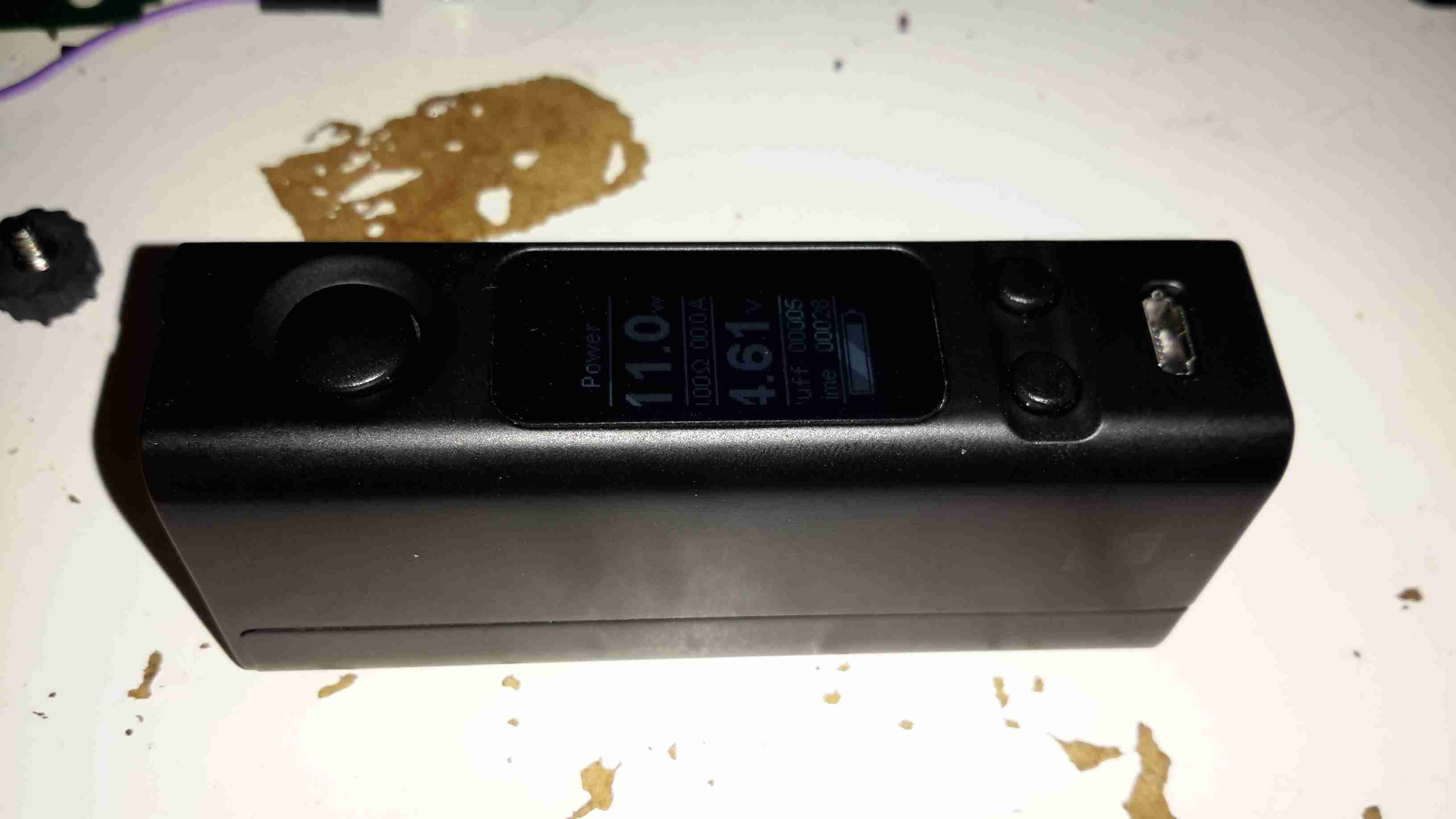
I’ve been a vaper now for many years, after giving up the evil weed that is tobacco. Here’s my latest acquisition in the vaping world, the JoyeTech eVIC 60W. This one is branded by Totally Wicked as the Forza VT60.
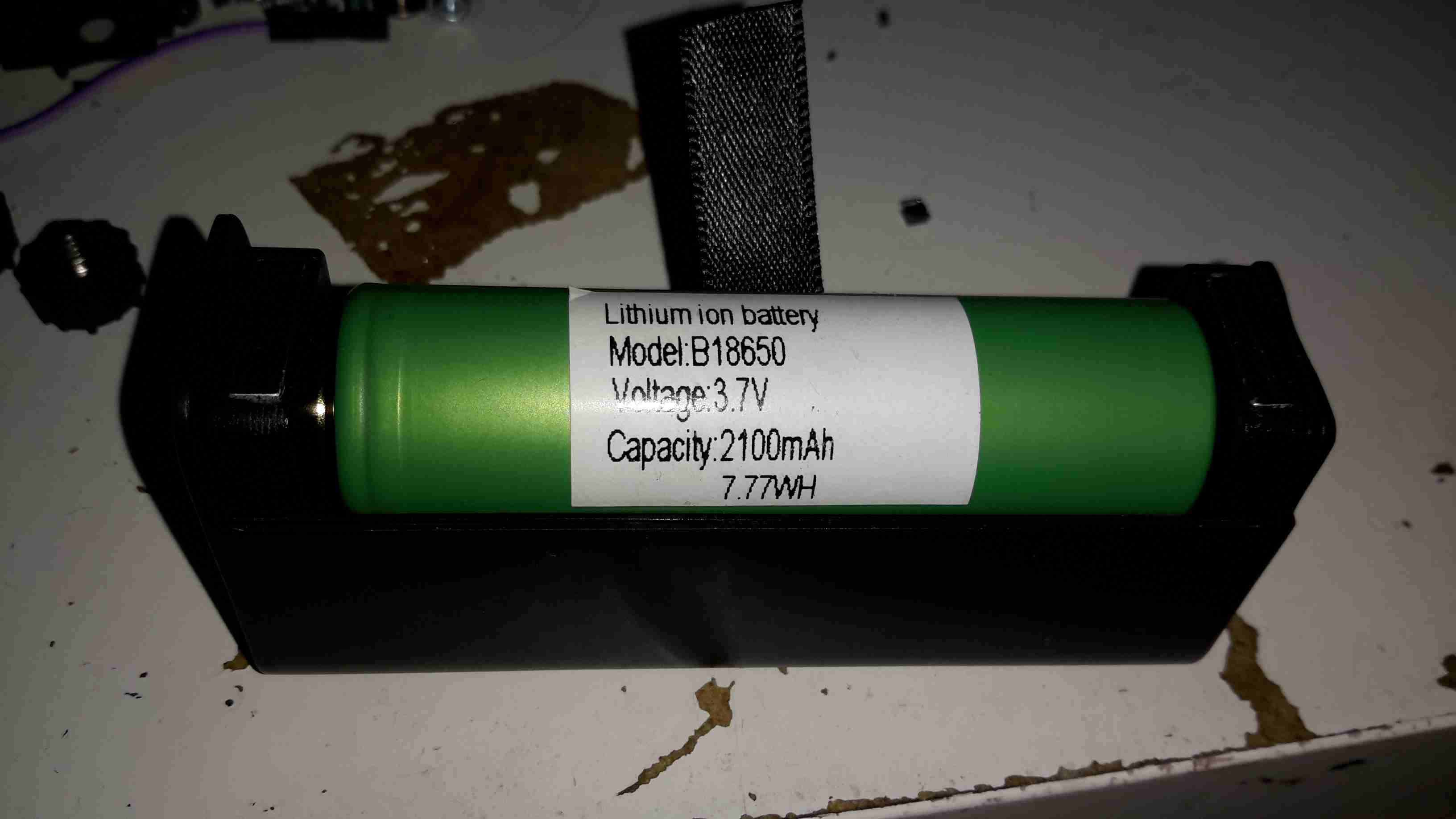
18650 Cell
Powered by a single 18650 Li-Ion cell, this one is a Sony VTC4 series, 2100mAh.
Under the battery a pair of screws hold the electronics in the main cast alloy casing.
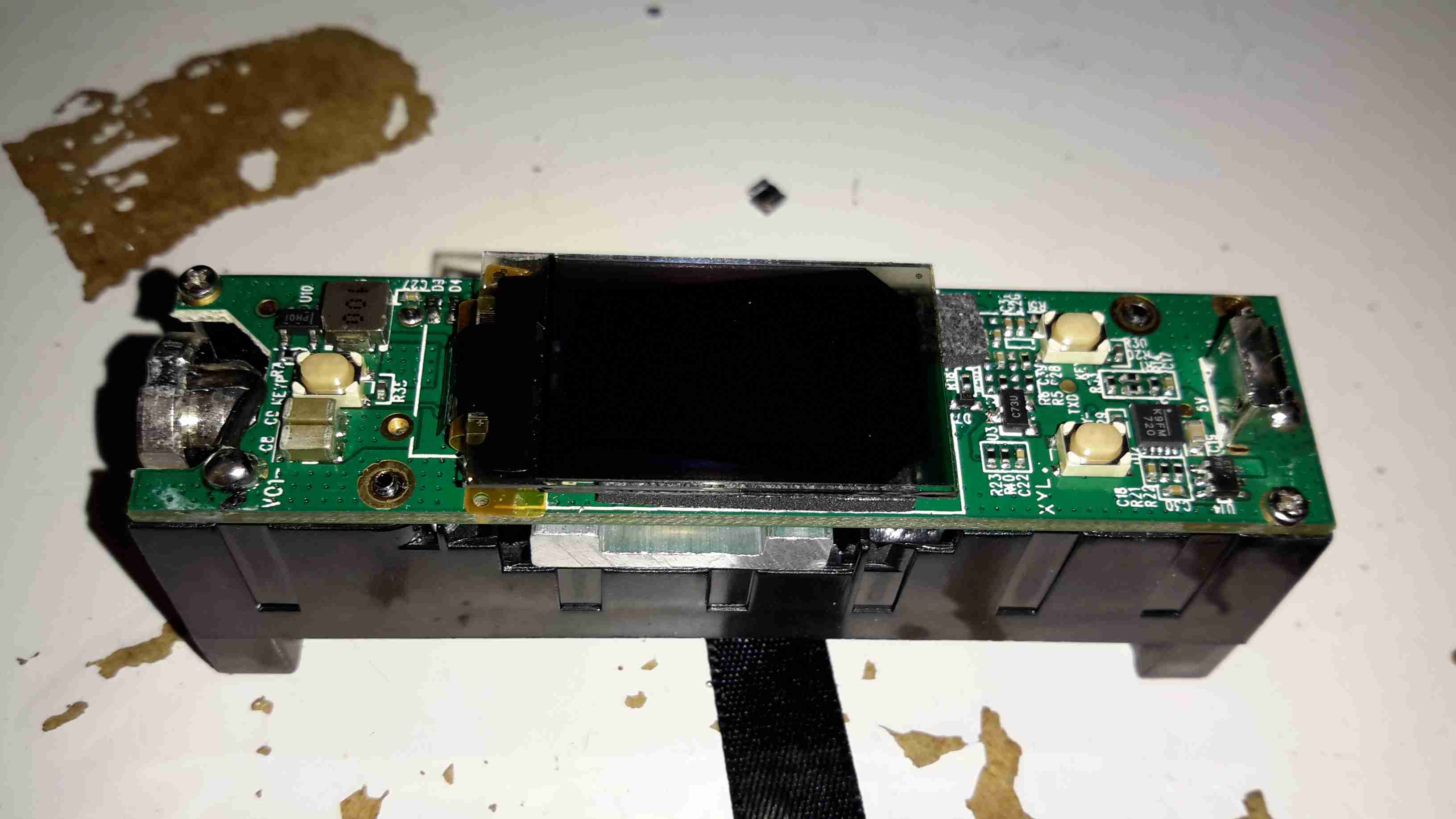
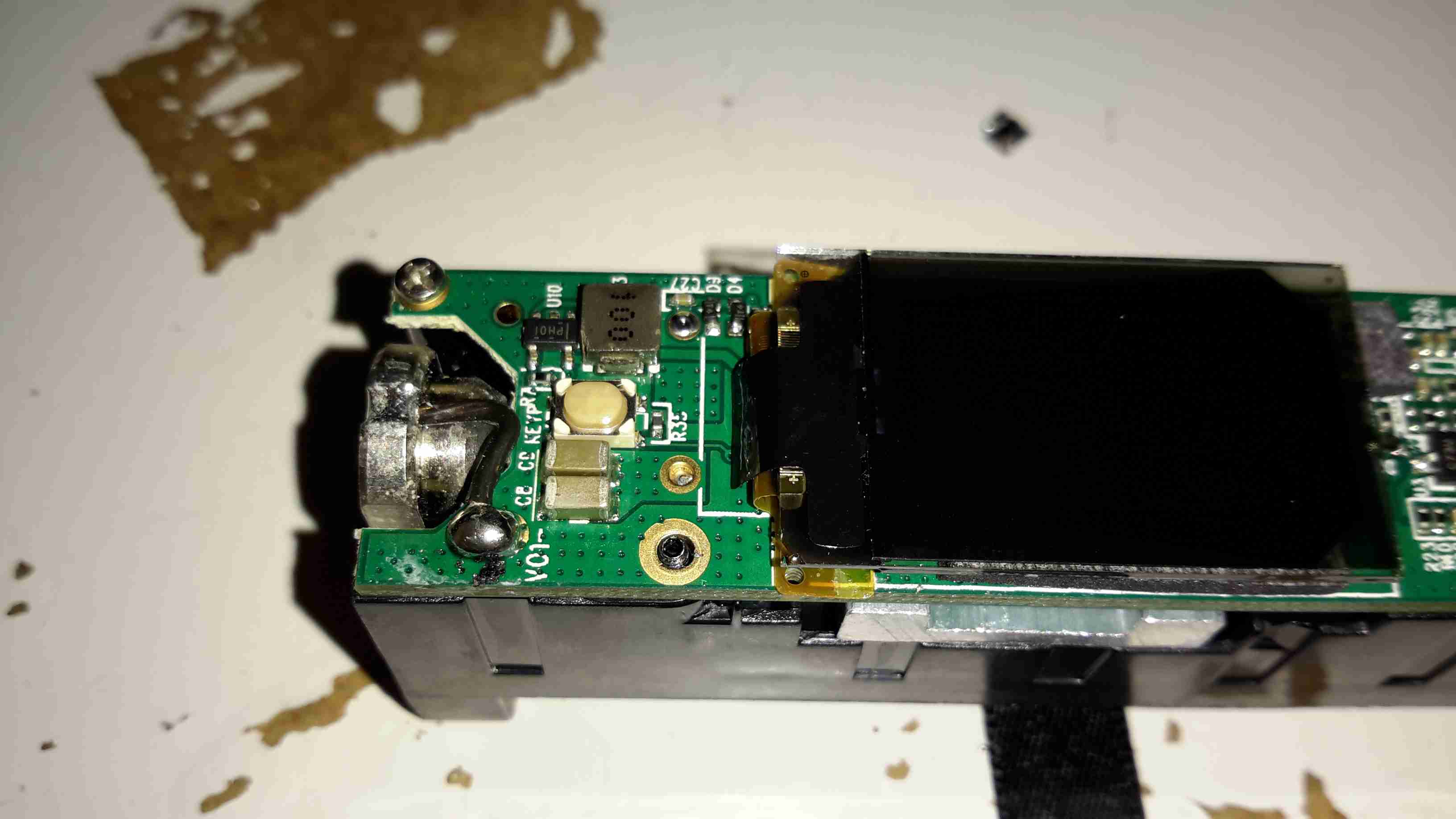
OLED Display
After removing the screws, the entire internal assembly comes out of the case, here’s the top of the PCB with the large OLED display in the centre.
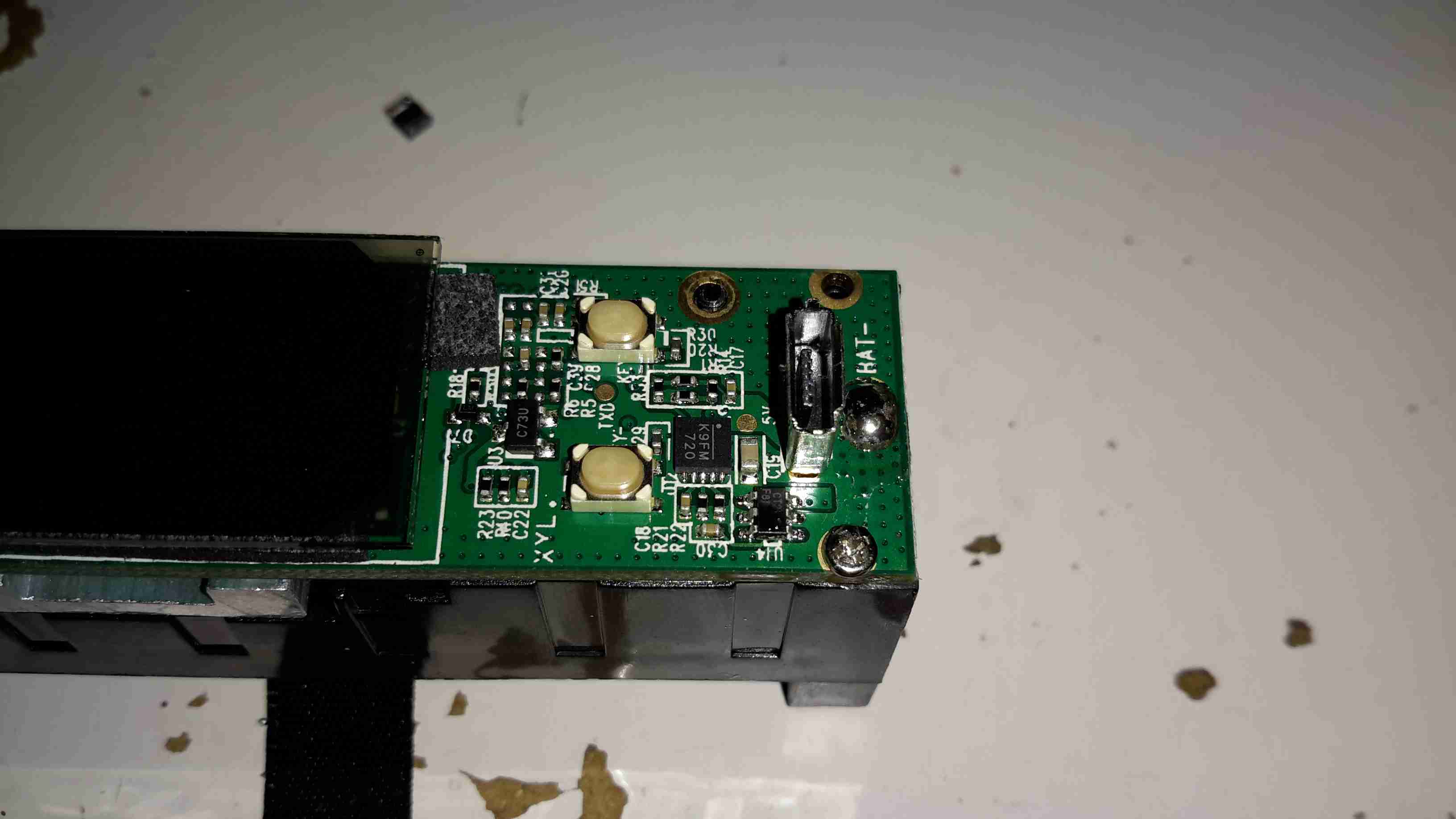
USB Jack
On the right side of the board is the USB jack for charging & firmware updates. The adjustment buttons are also at this end.
Output
On the left side of the board is the main output connector & the fire button. Unlike many eCigs I’ve torn down before, the wiring in this one is very beefy – it has to be to handle the high currents used with some atomizers – up to 10A.
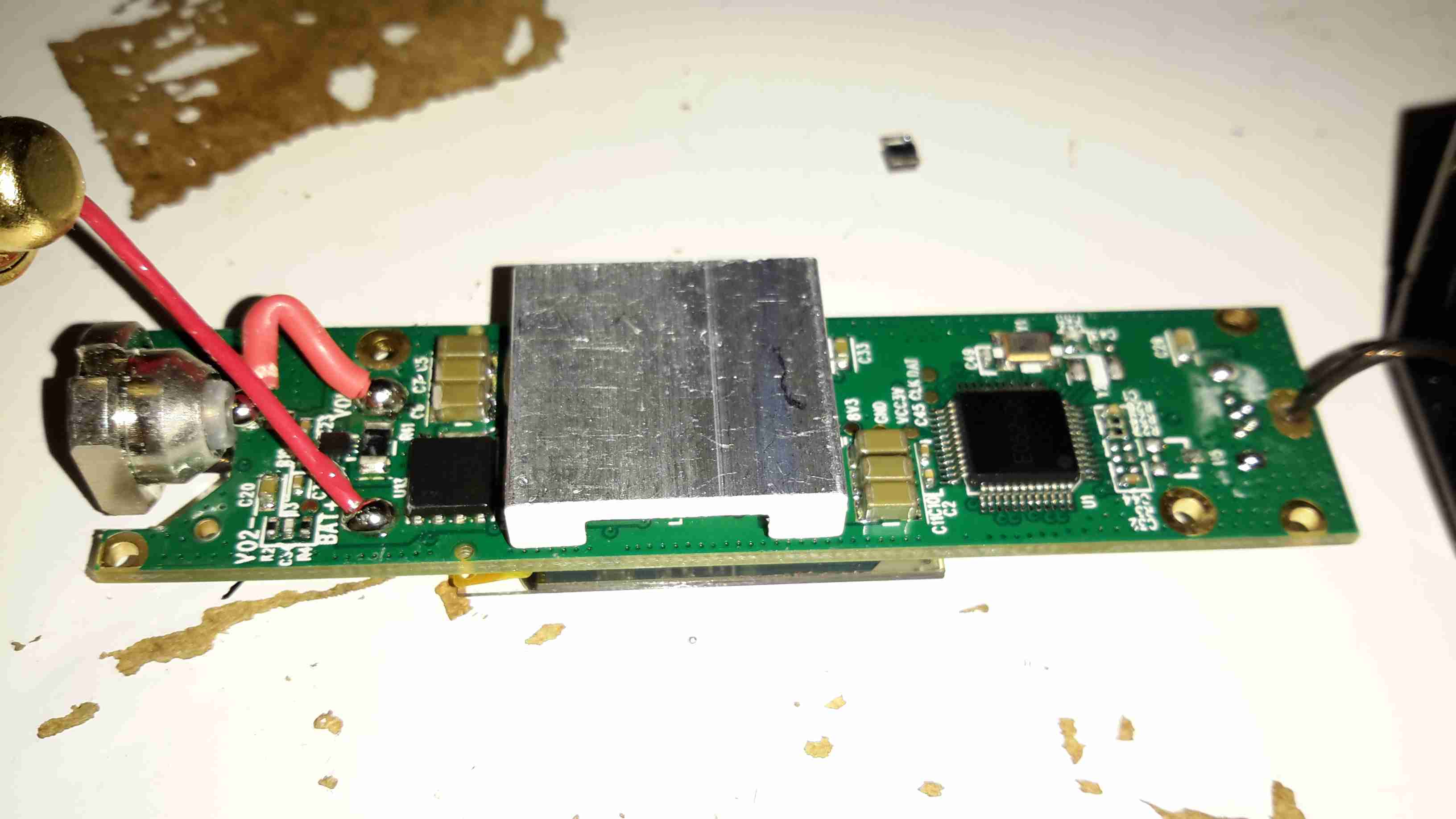
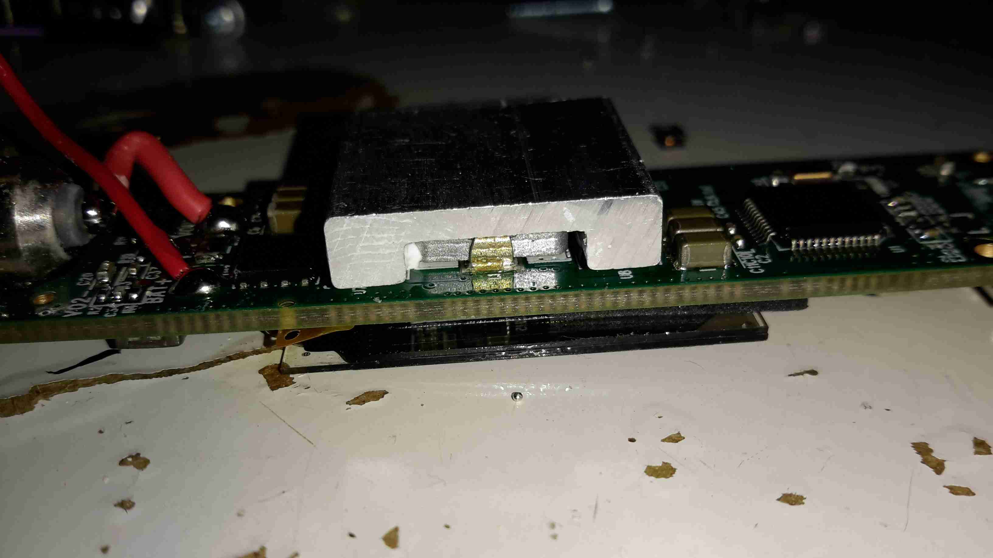
PCB Reverse
Removing the board from the battery holder shows the main power circuitry & MCU. The aluminium heatsink is thermally bonded to the switching MOSFETs, a pair under each end. The switching inductor is under the gap in the centre of the heatsink.
DC-DC Converter
A close up of the heatsink shows the very slim inductor under the heatsink.
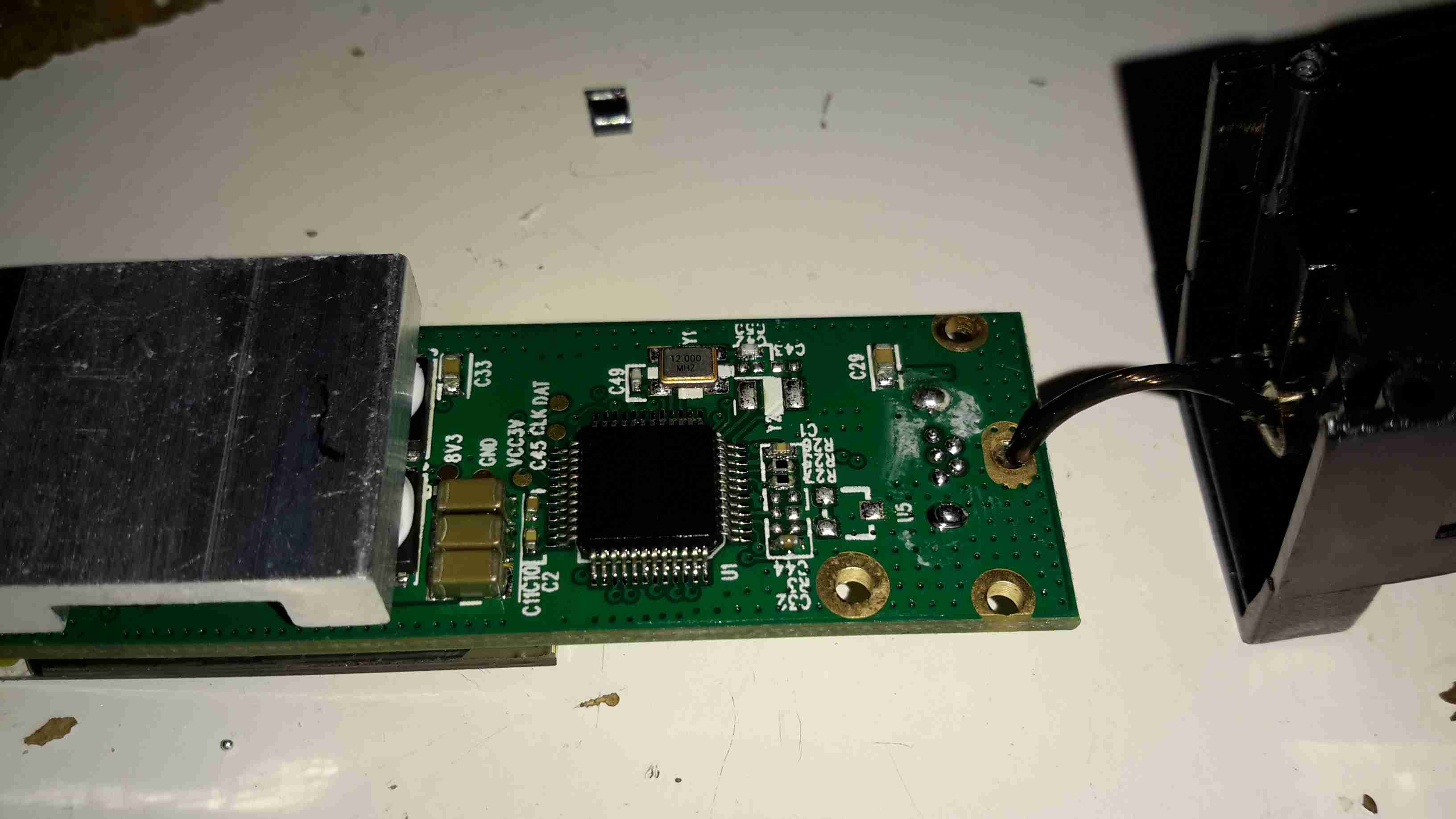
Microcontroller
The main MCU in this unit has a very strange part number, which I’ve been unable to find information on, but it’s probably 8081 based.
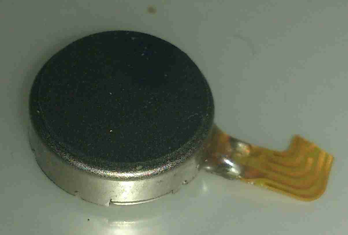
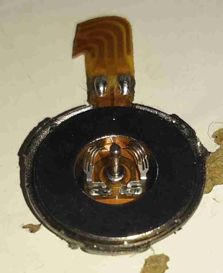
For a while I’ve wondered how these pancake type (AKA “Shaftless”) vibration motors operate, so I figured I’d mutilate one to find out.
Pancake Vibration Motor
These vibrators are found in all kinds of mobile devices as a haptic feedback device, unlike older versions, which were just micro-sized DC motors with an offset weight attached to the shaft, these don’t have any visible moving parts.
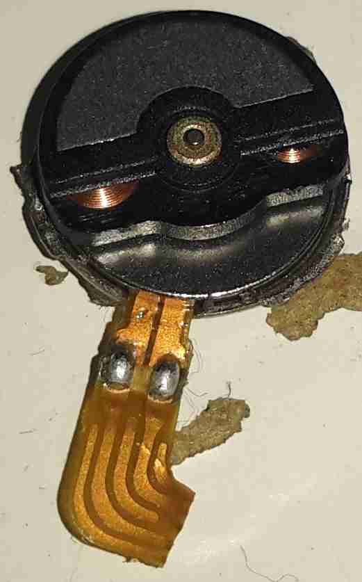
Cover Removed
These devices are crimped together, so some gentle attack with a pair of snips was required to get the top cover off.
It turns out these are still a standard rotary DC motor, in this case specifically designed for the purpose. The rotor itself is the offset weight, just visible under the steel half-moon shaped section are the armature coils.
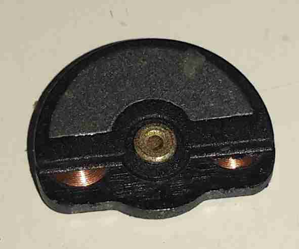
Weighted Rotor
The armature lifts off the centre shaft, the coils can clearly be seen peeking out from under the counterweight.
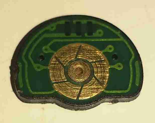
Commutator
The underside of the armature reveals the commutator, which in this device is just etched onto the PCB substrate, the connections to the pair of coils can be seen either side of the commutator segments.
Brushes
The base of the motor holds the brushes in the centre, the outer ring is the stationary permanent magnet. These brushes are absolutely tiny, the whole motor is no more than 6mm in diameter.
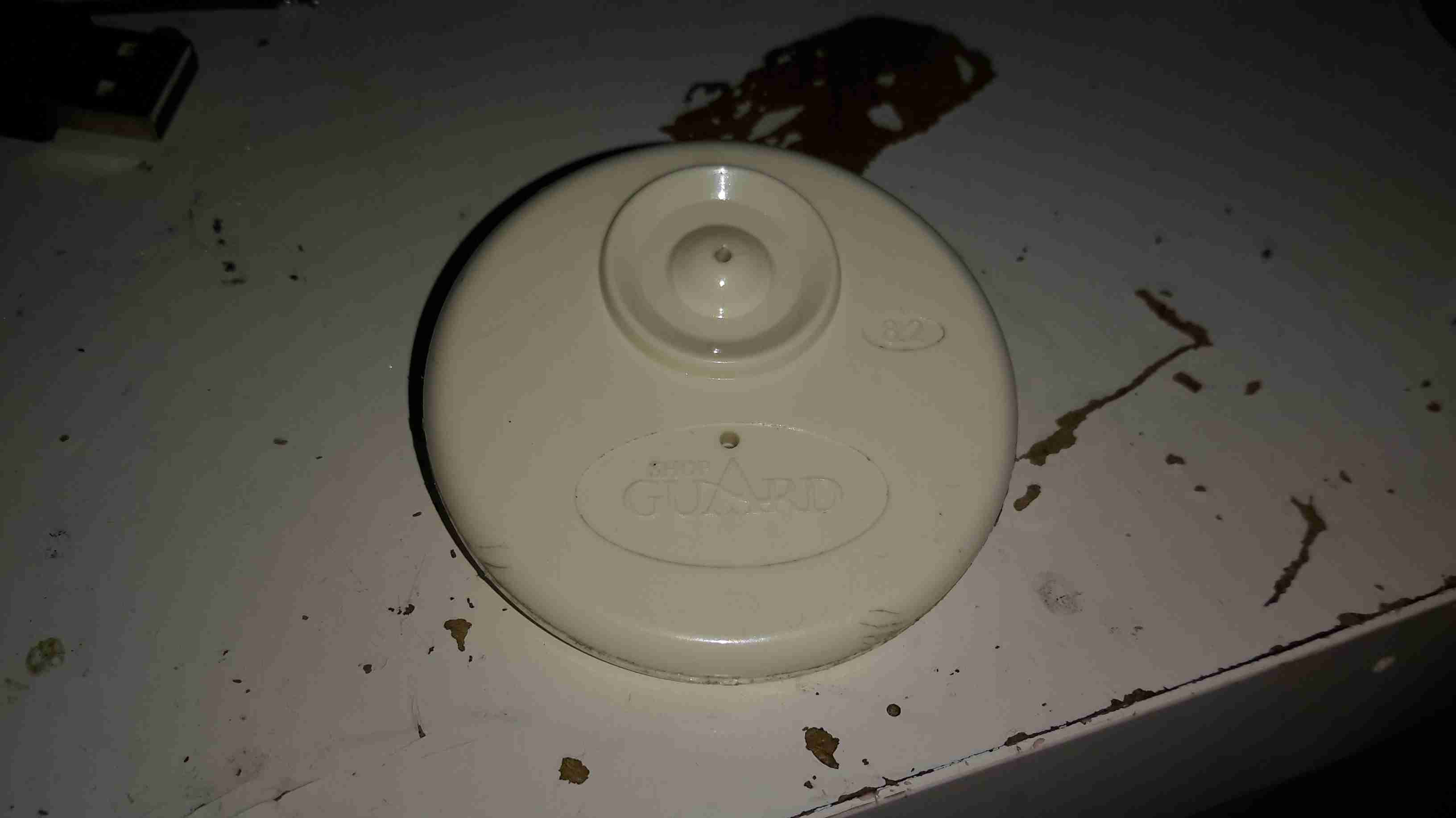
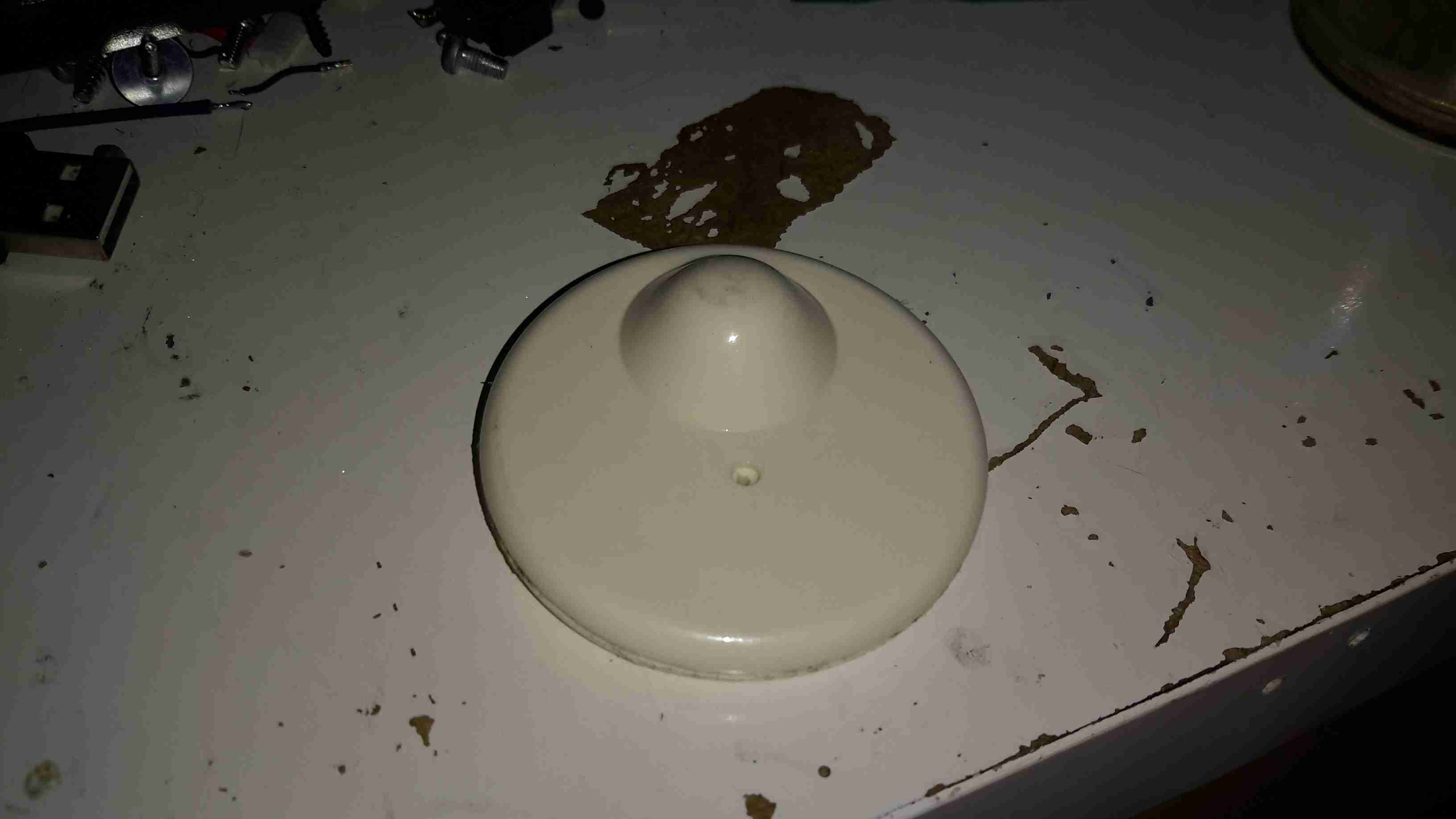
Everyone at some stage must have seen these EAS security tags in shops, usually attached to clothing with a steel pin. As some of this year’s presents had been left with the tags attached, I had to forcibly remove them before wrapping could commence.
Reverse Side
These are just a plastic disc about 50mm in diameter, with an internal locking mechanism & RF tag inside.
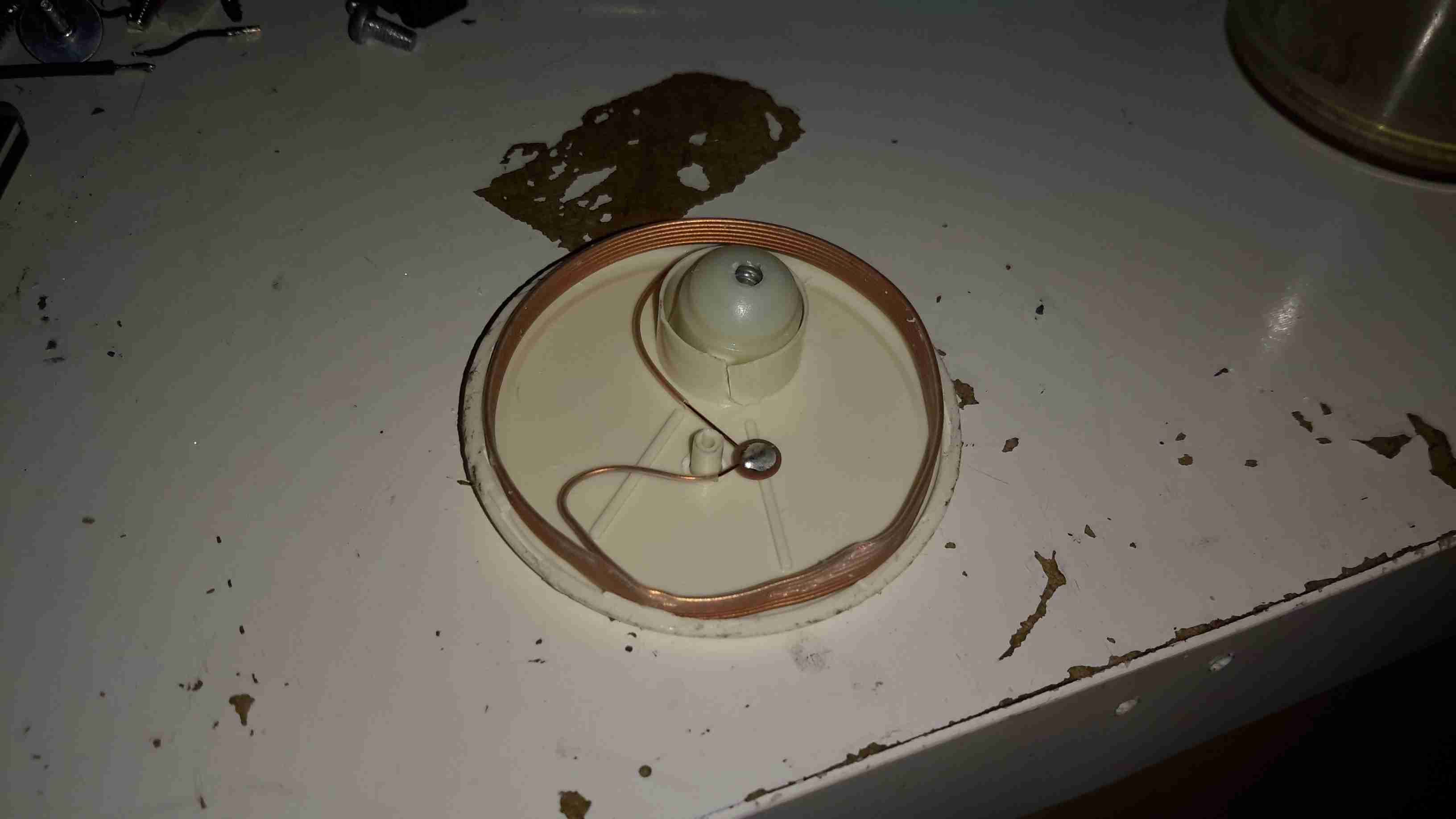
RF Coil
After some careful attack with a saw around the glue seam, the tag comes apart into it’s halves. The RF coil & it’s ceramic capacitor can be seen wrapped around the outside of the tag. The capacitor in this case isn’t even epoxy dipped to save that extra 0.0001p on the manufacturing price. In the top centre is the pin locking mechanism, enclosed in a small plastic pill.
Lock Pill
Popping off the back cap of the lock shows it’s internals.
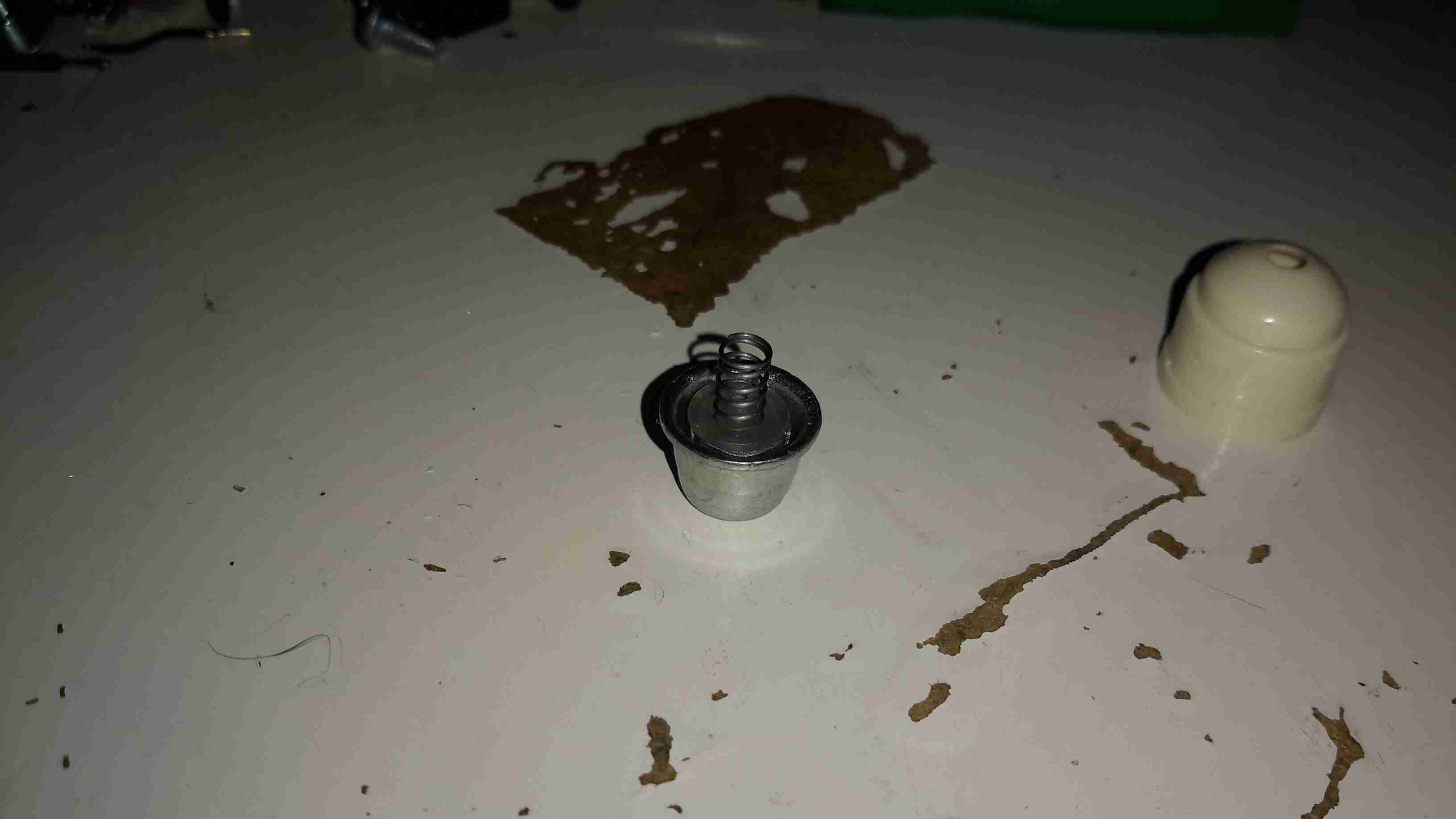
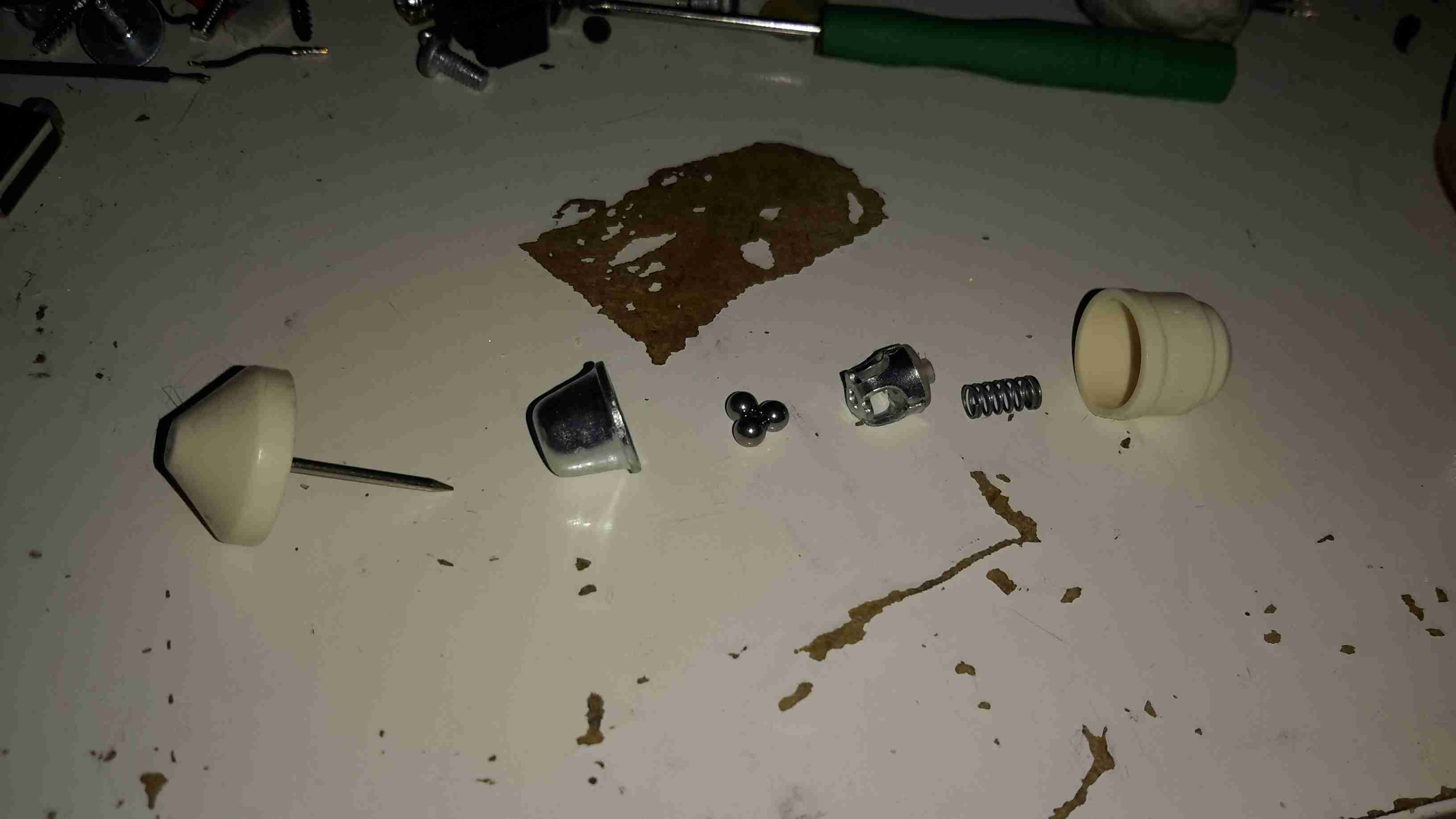
Ball Bearing Lock Assembly
The lock itself is very simple. The centre section, held in place by a spring, carries 3 small ball bearings. The outer metal frame of the lock is conical in shape.
When the pin is pushed into the tag, the conical shape of the lock chamber causes the ball bearings to grab onto it, helped by the action of the spring that pushes the ball bearing carrier further into the cone.
This also means that any attempt to force the mechanism causes it to lock tighter onto the pin.
In normal operation, removal is achieved by a strong magnet that pulls the ball bearing carrier back slightly against it’s spring, allowing the pin to disengage & be pulled out.
This design is incredibly simple & cheap to make, and gains it’s locking strength from friction alone.
I would consider the RF coil being around the outer edge of the device a bit of a security risk – a quick chop with a sharp pair of wire cutters would disable the tag’s alarm functionality instantly. Making the coil slightly smaller & keeping it out of reach of the edge of the tag would help in this regard.
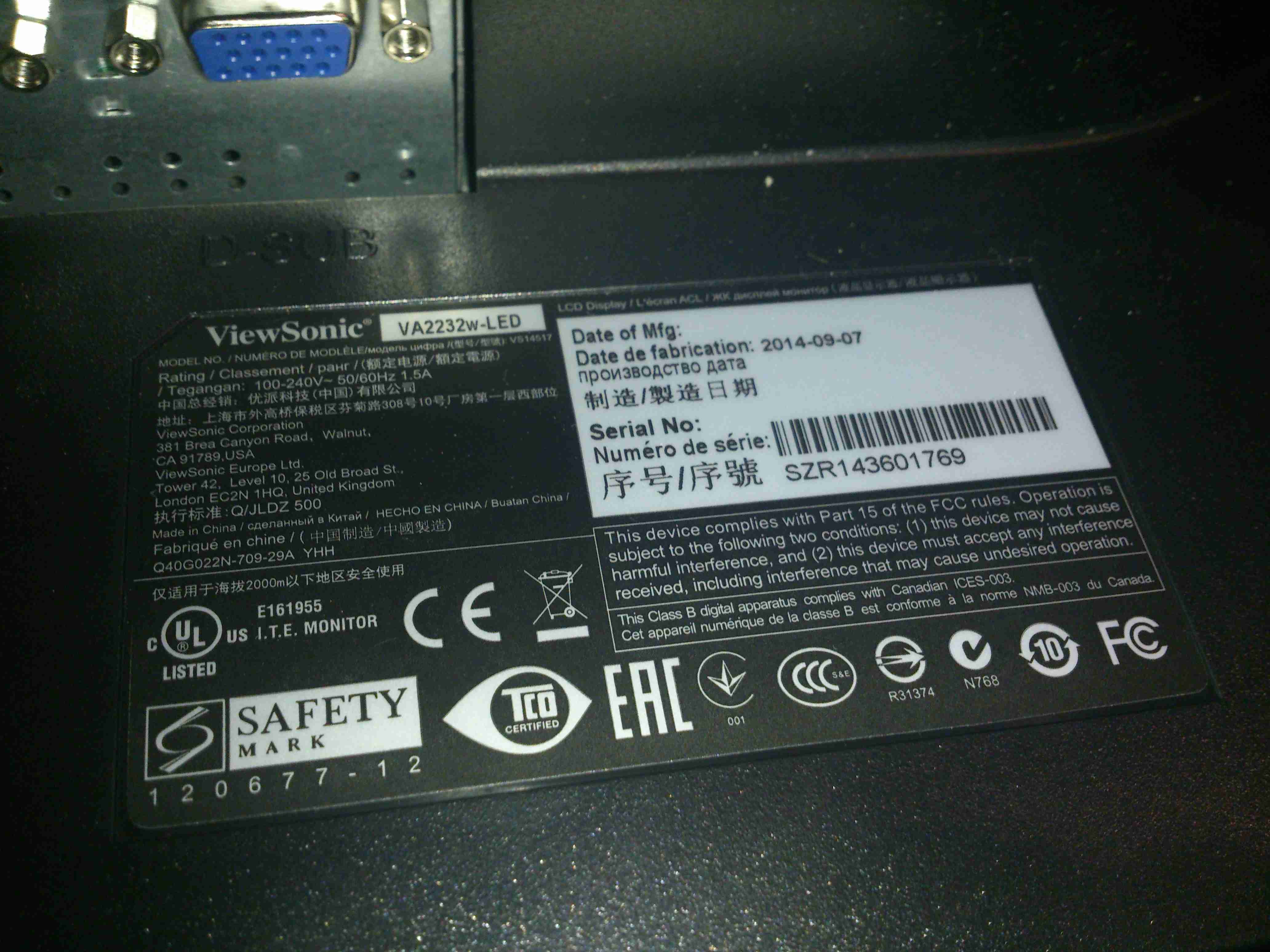
On the quest to get things on board replaced that are heavy users of power, the monitor in the main cabin was next. The original CCFL-backlit monitor was very heavy on 12v power, at 5A. This meant falling asleep watching TV would result in severely flattened batteries.
Replacement with a suitable LED-backlit monitor was definitely required. The cheapest on eBay was a ViewSonic VA2232W-LED, so I took to work converting it from 240v to 12v operation.
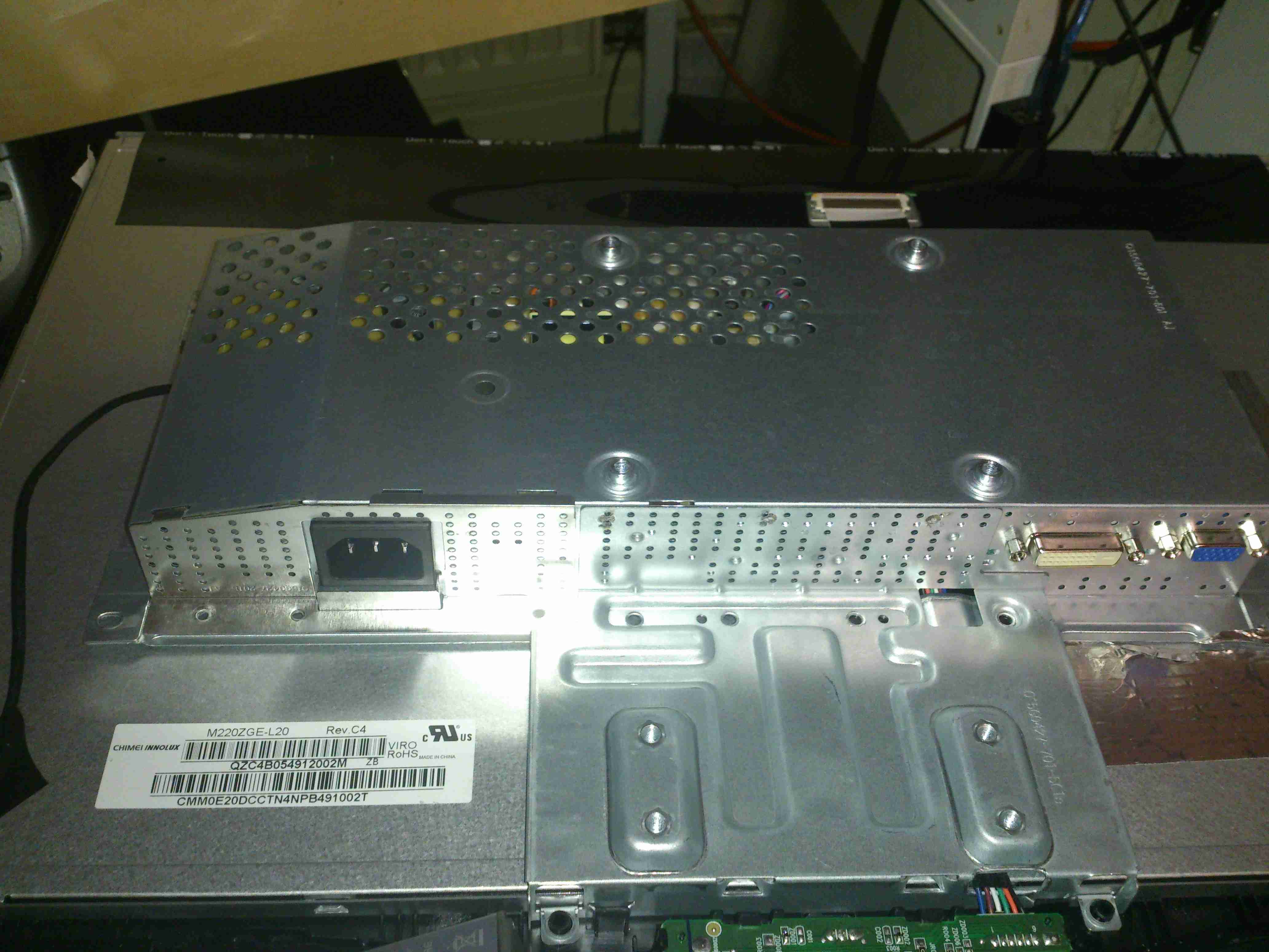
Back Cover Removed
There are no screws holding these monitors together, so a spudger & frequent swearing got the back off. The shield holding the circuitry is also not screwed down, only attached to the back of the LCD panel with aluminium shielding tape.
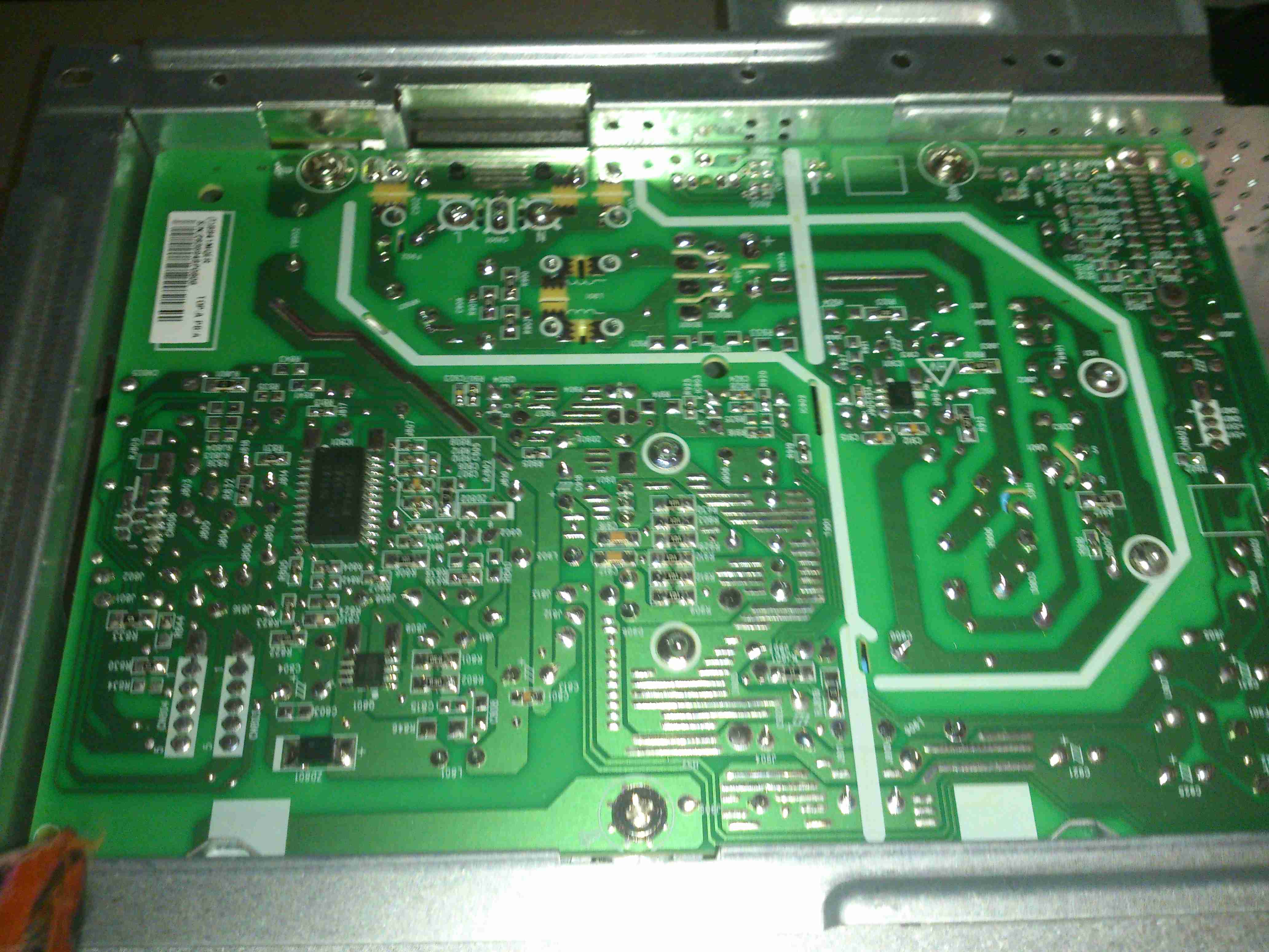
Power PCB Trackside
Once the tape has been cut, the main power board is accessible. The large IC on the left is the main backlight LED driver.
In this case the monitor requires a pair of rails from the supply, 18.5v for the backlight circuitry & 5v for the logic.
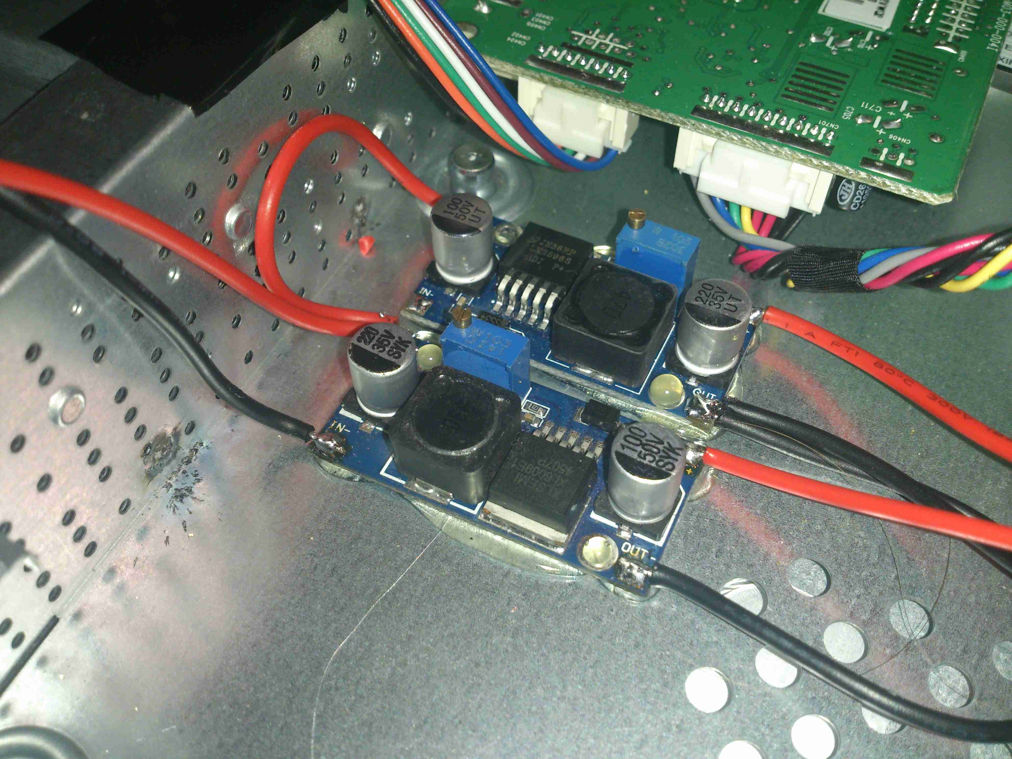
DC-DC Regulators
A pair of DC-DC converters has been fitted in the small space between the power & control boards.
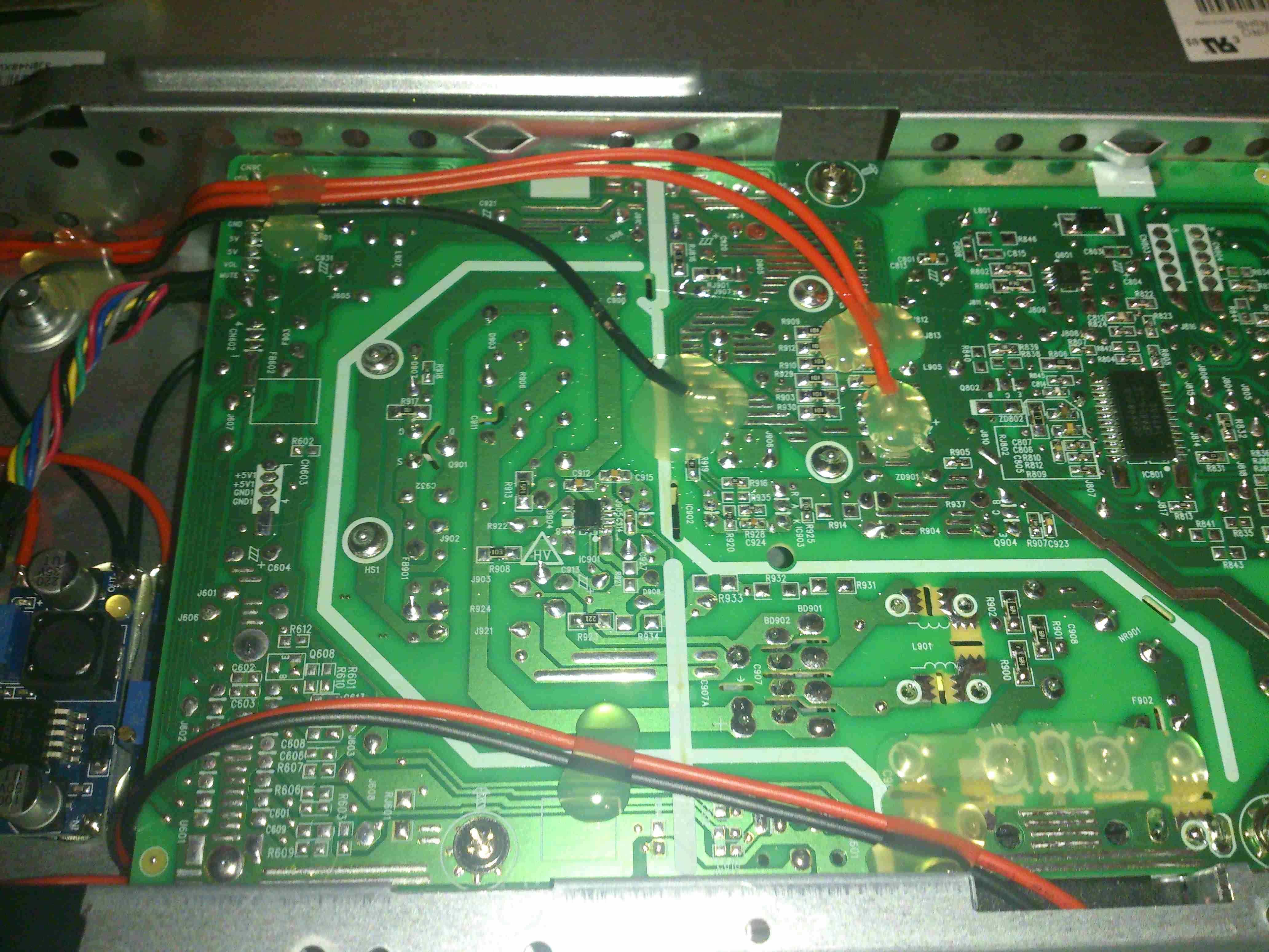
PCB Connection Points
To save me some work & keep maximum compatibility, I’ve not modified the existing supply, just attached the new DC-DC converter outputs onto the corresponding outputs of the factory PSU. The 12v input leads are routed out of the same gap as the mains IEC connector, with some hot glue over the mains input solder points to provide some more insulation.
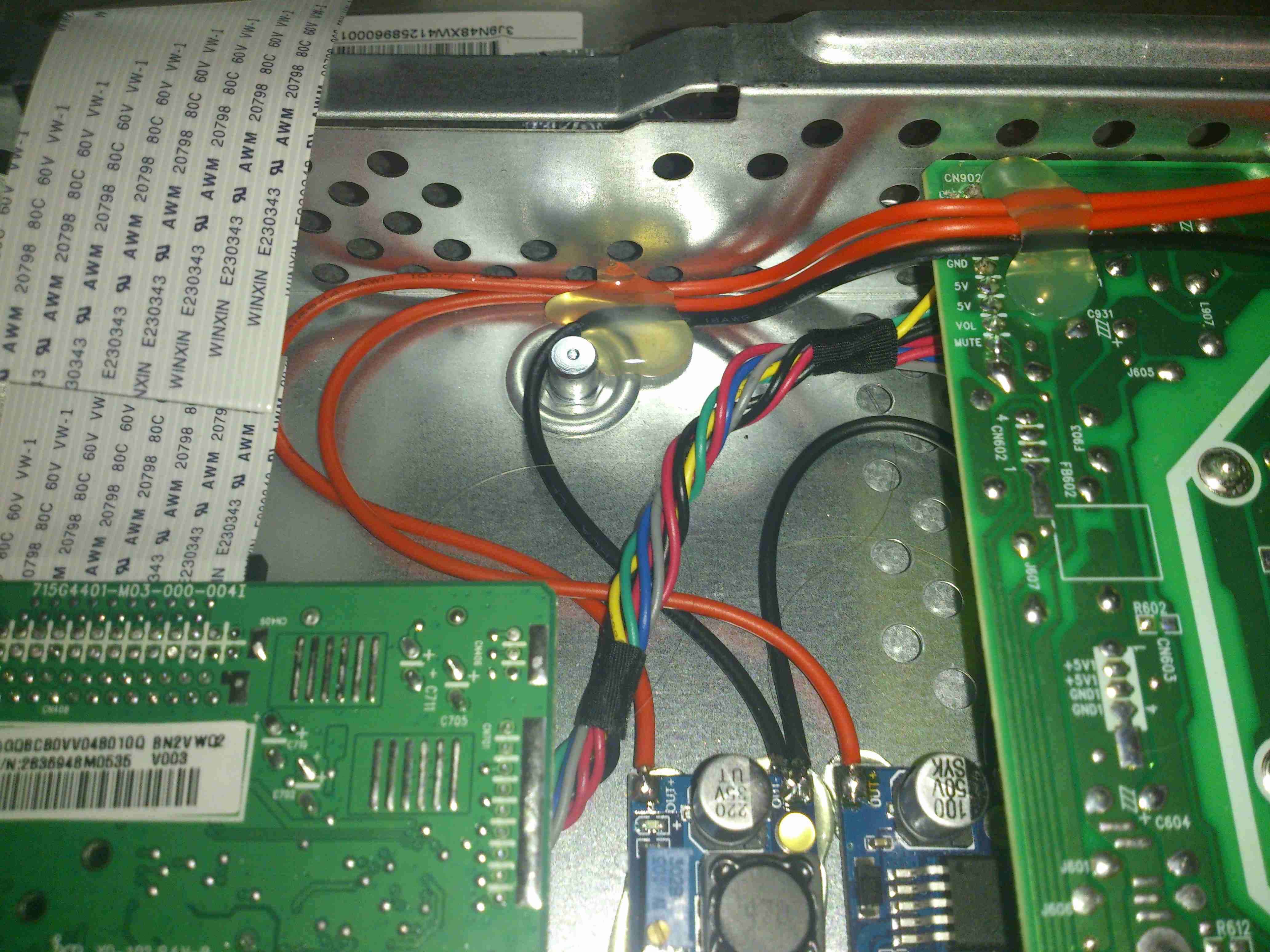
Wiring Tidied
The wiring is tidied up with hot glue so the back cover will go back on.
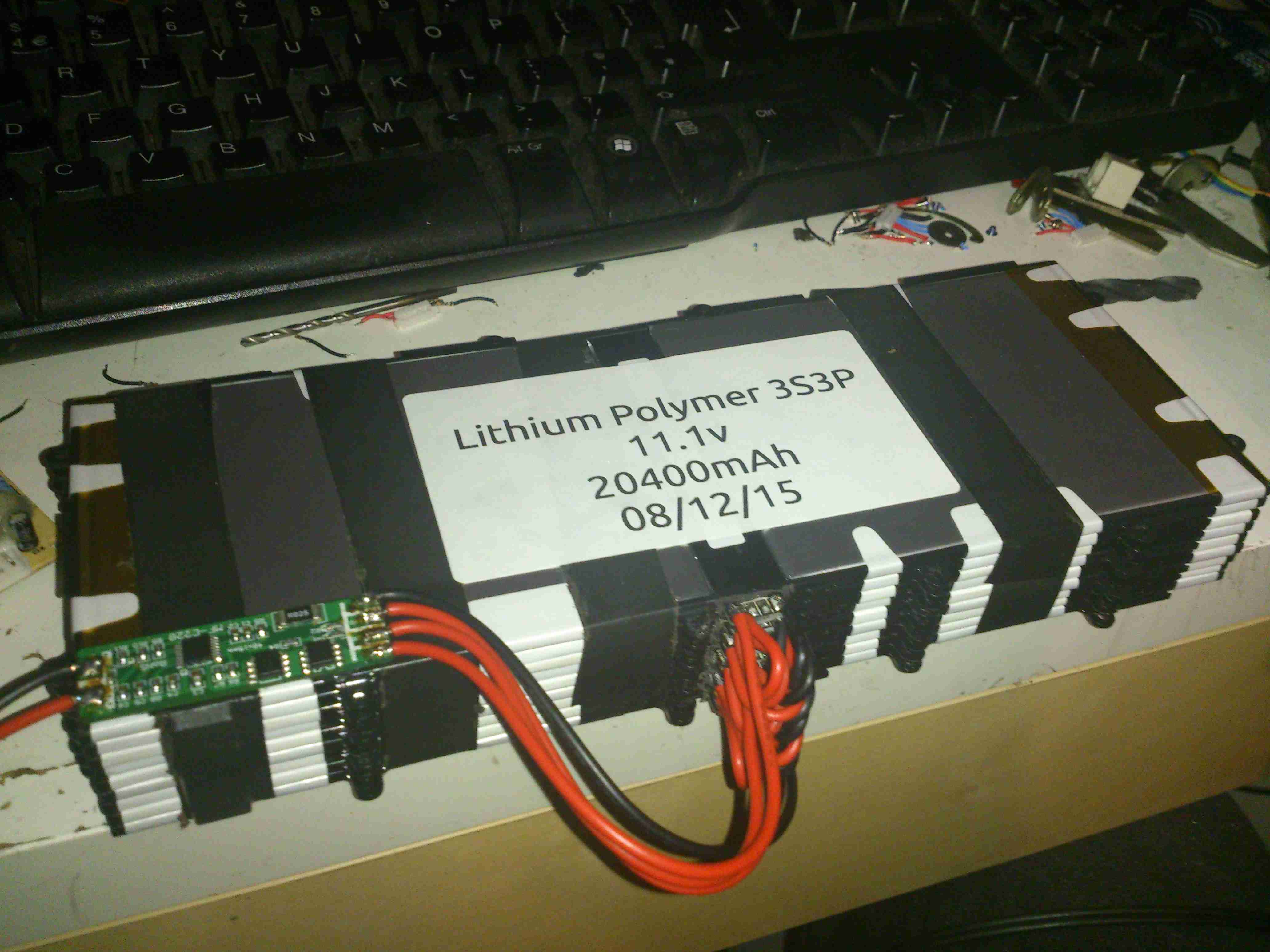
In the past, I’ve used RC type LiPo packs for my mobile power requirements, but these tend to be a bit bulky, since they’re designed for very high discharge current capability – powering large motors in models is a heavy job.
I recently came across some Samsung Galaxy Tab 10.1 battery packs on eBay very cheaply, at £2.95 a piece. For this price I get 6800mAh of capacity at 4.2v, for my 12v requirements, 3 packs must be connected in series, for a total output of 12.6v fully charged.
For an initial pack, I got 9 of these units, to be connected in 3 sets of 3 to make 20Ah total capacity.There are no control electronics built into these batteries – it’s simply a pair of 3400mAh cells connected in parallel through internal polyfuses, and an ID EEPROM for the Tab to identify the battery.
This means I can just bring the cell connections together with the original PCB, without having to mess with the welded cell tabs.
Battery Pack
Here’s the pack with it’s cell connections finished & a lithium BCM connected. This chemistry requires close control of voltages to remain stable, and with a pack this large, a thermal runaway would be catastrophic.
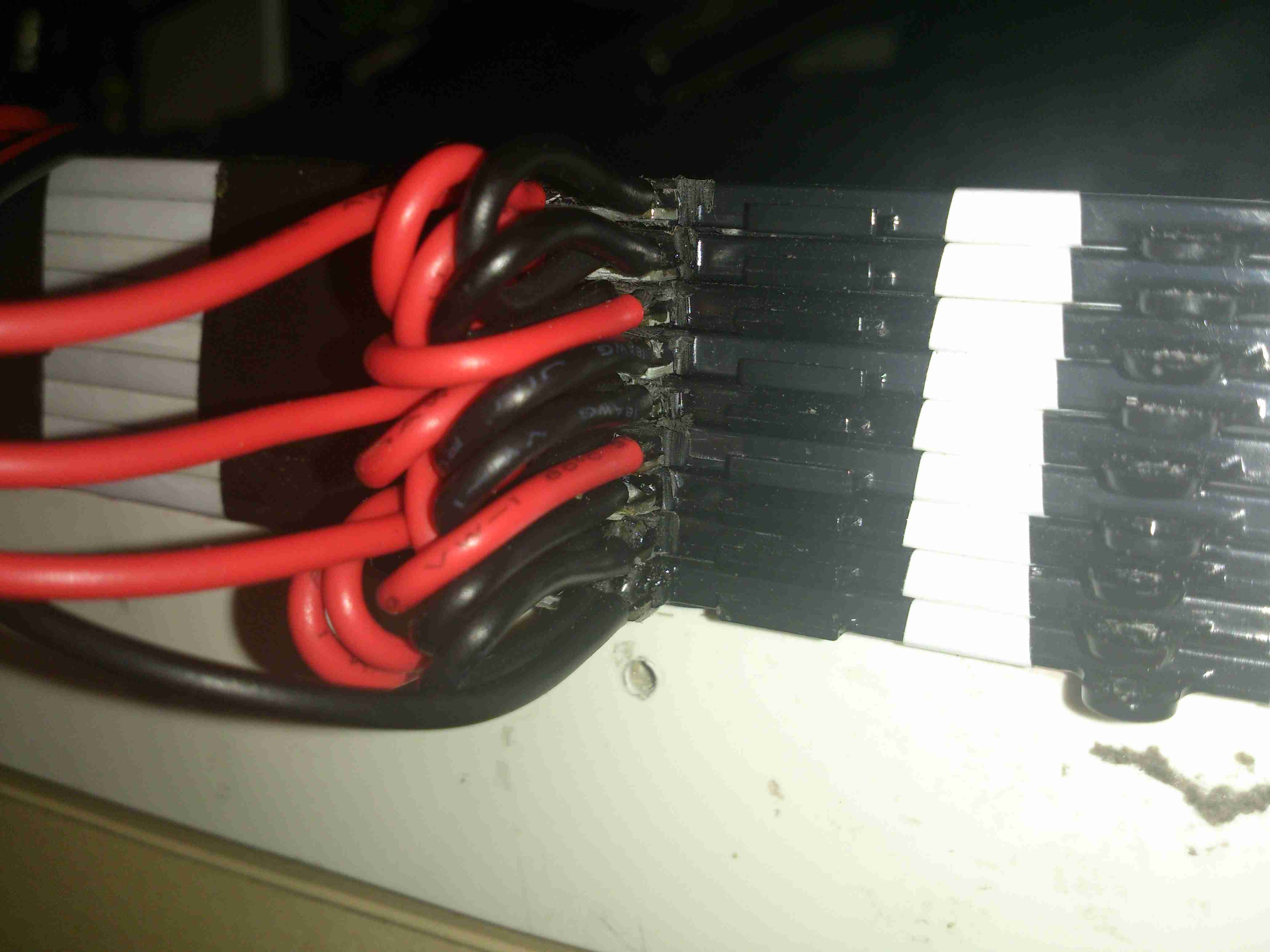
Cell Links
The OEM battery connector has been removed, and my series-parallel cell connections are soldered on, with extra lead-outs for balancing the pack. This was the most time-consuming part of the build.
If all goes well with the life of this pack for utility use, I’ll be building another 5 of these, for a total capacity of 120Ah. This will be extremely useful for portable use, as the weight is about half that of an equivalent lead-acid.
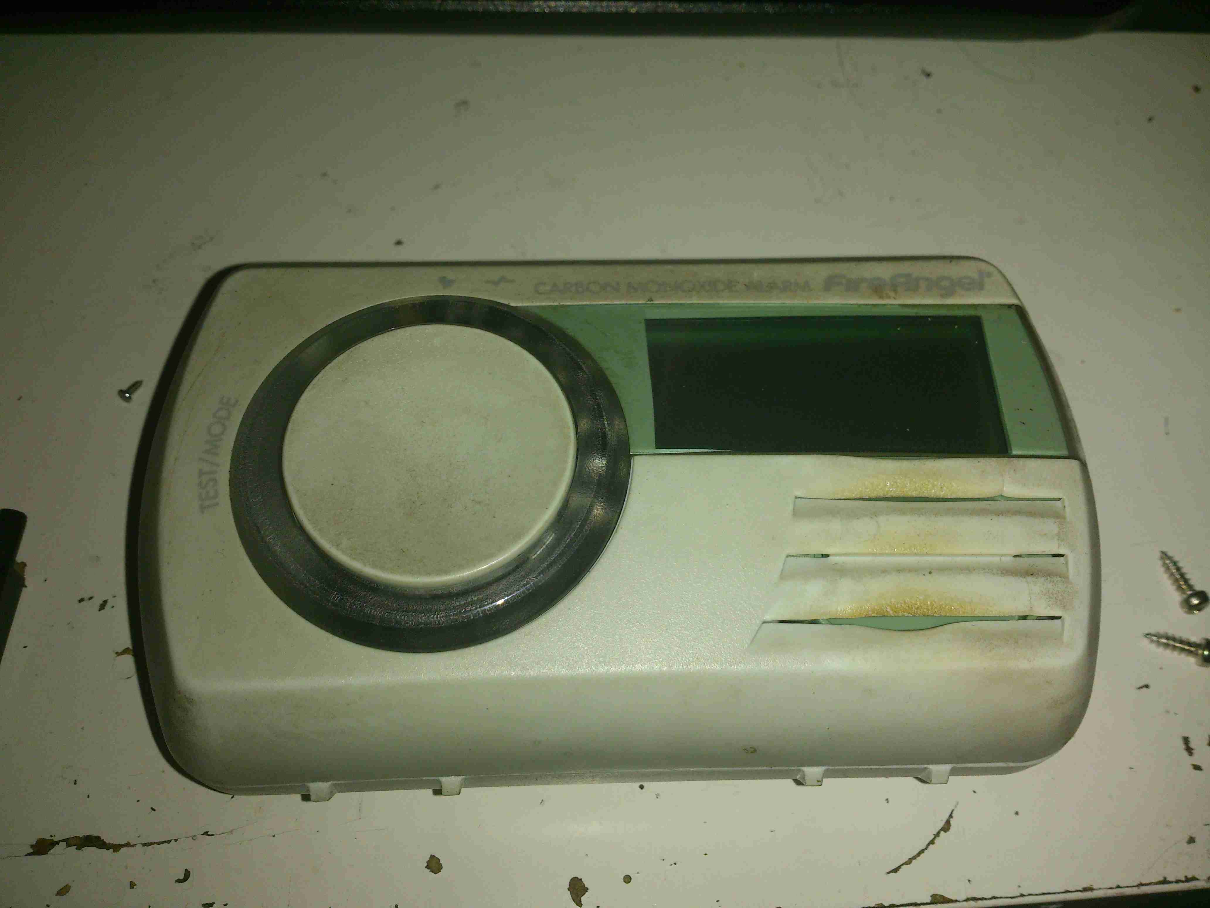
This detector has now been retired from service since it’s a fair bit out of date. So here’s the teardown!
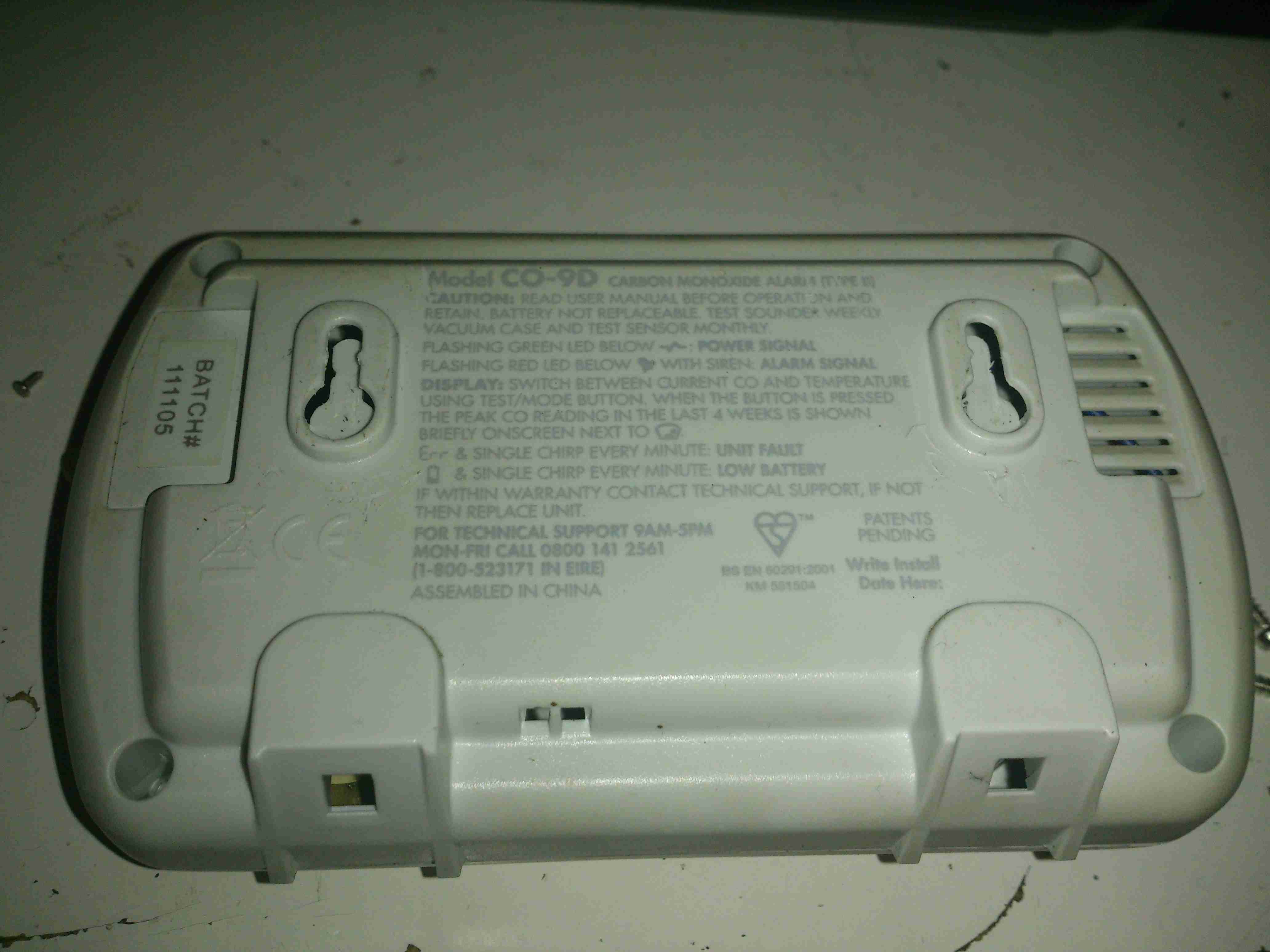
Information
Unlike older detectors, this unit has a built in battery that never needs replacing during the life of the sensor, so once the unit reaches it’s expiry date it’s just trashed as a whole.
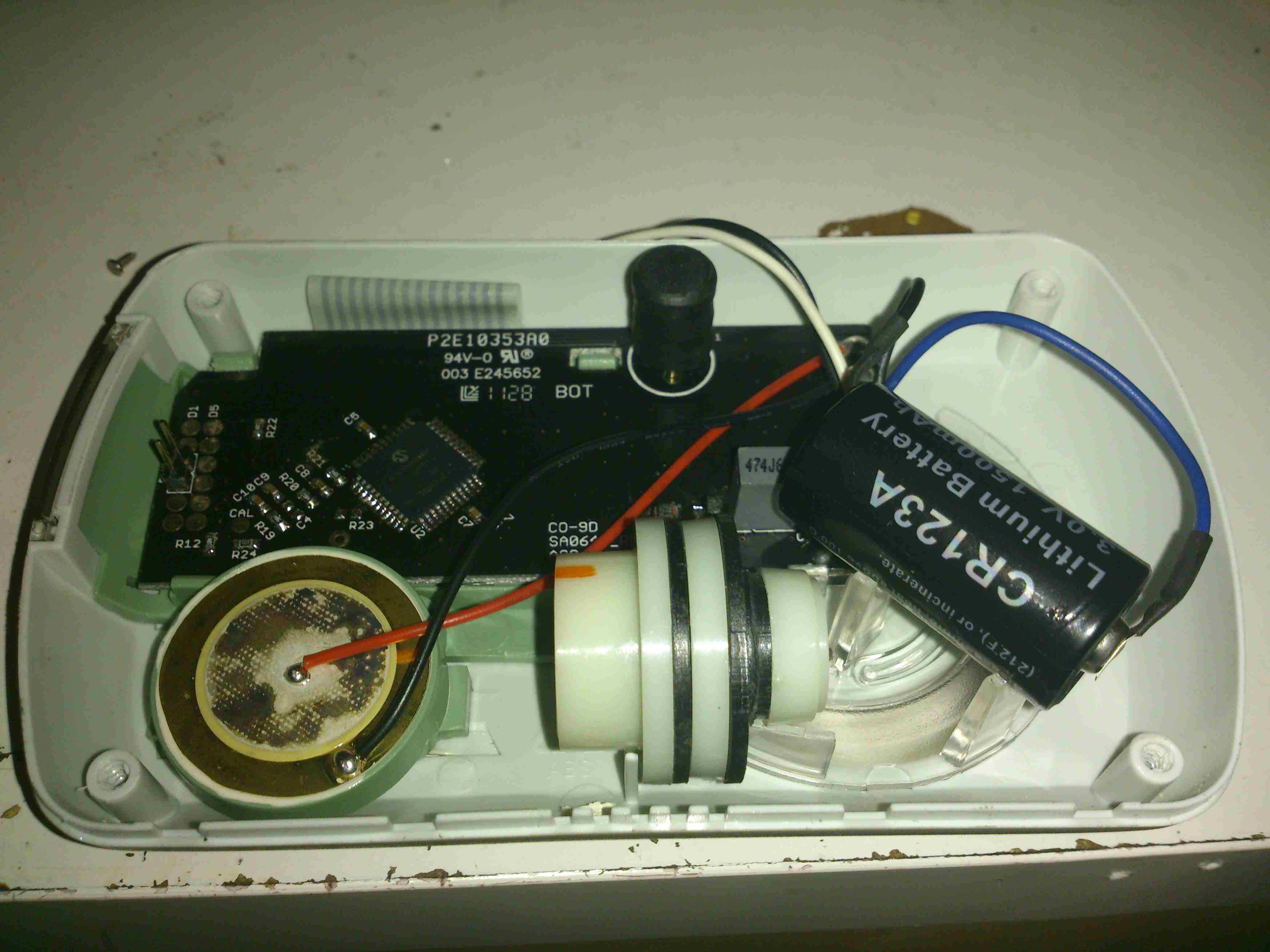
Cover Removed
4 screws hold the cover on, here’s the internals of the detector. There’s a 3v CR123A LiMnO² cell at the right for power, rated at 1500mAh. A 7 year life is quite remarkable on a single cell!
The sensor is just to the left of the lithium cell, and is of quite unusual construction. Previous CO sensor cells I’ve seen have been small cylinders with a pair of brass pins. This one appears to use a conductive plastic as the connections. These sensors contain H²SO⁴ so they’re a bit hazardous to open.
There are no manufacturer markings on the sensor & I’ve not been able to find any similarly shaped devices, so I’m unsure of it’s specifications.
The alarm sounder is on the left, the usual Piezo disc with a resonator to increase the loudness.
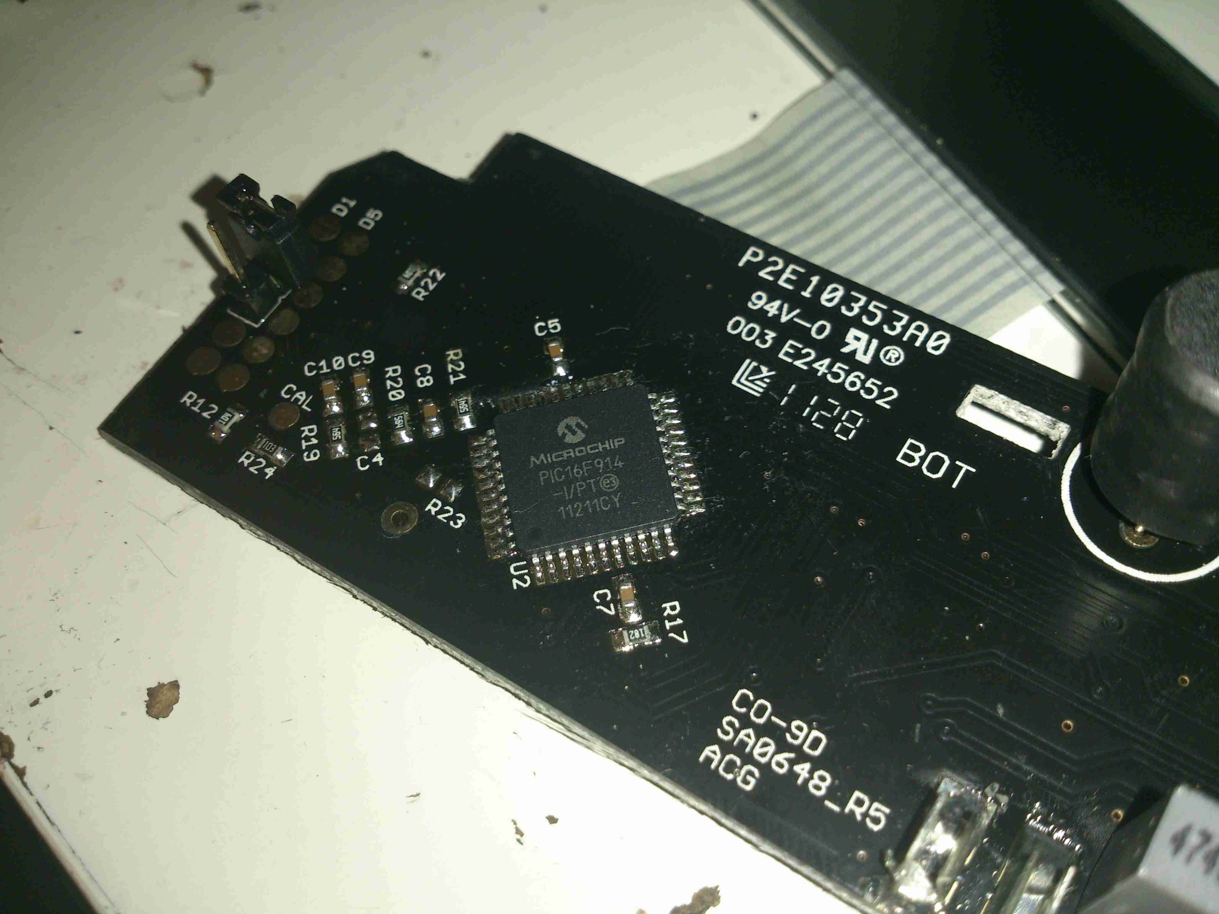
Microcontroller
The brains of the device are provided by a Microchip PIC16F914 microcontroller. This is a fairly advanced device, with many onboard features, and NanoWatt™ technology, standby power consumption is <100nA according to Microchip’s Datasheet. This would explain the incredible battery life.
The choke just at the right edge of the photo is actually a transformer to drive the Piezo sounder at high voltage.
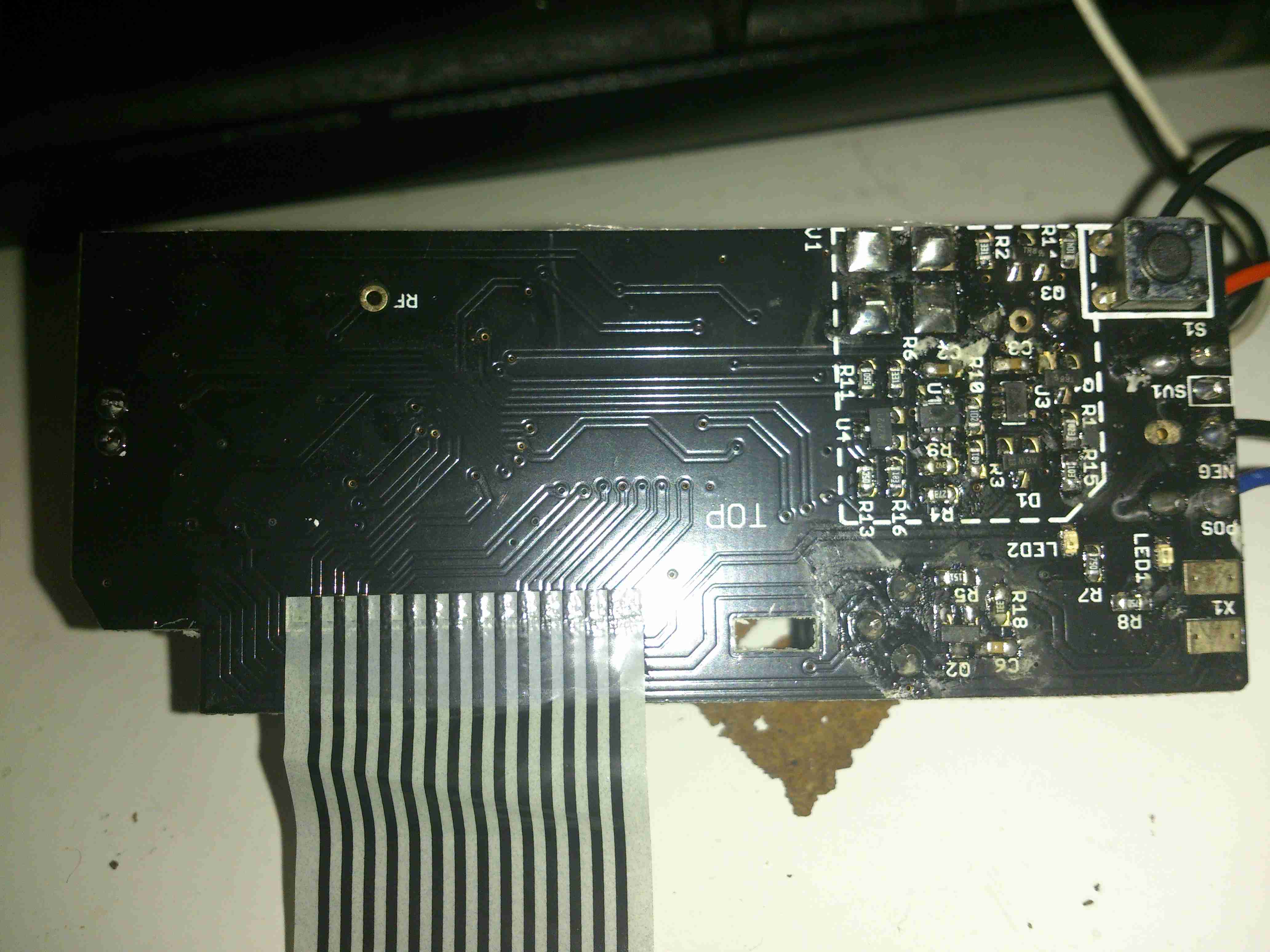
PCB Reverse
Here’s the PCB with the LCD frame removed. Not much to see on the this side, the silence/test button top right & the front end for the sensor.
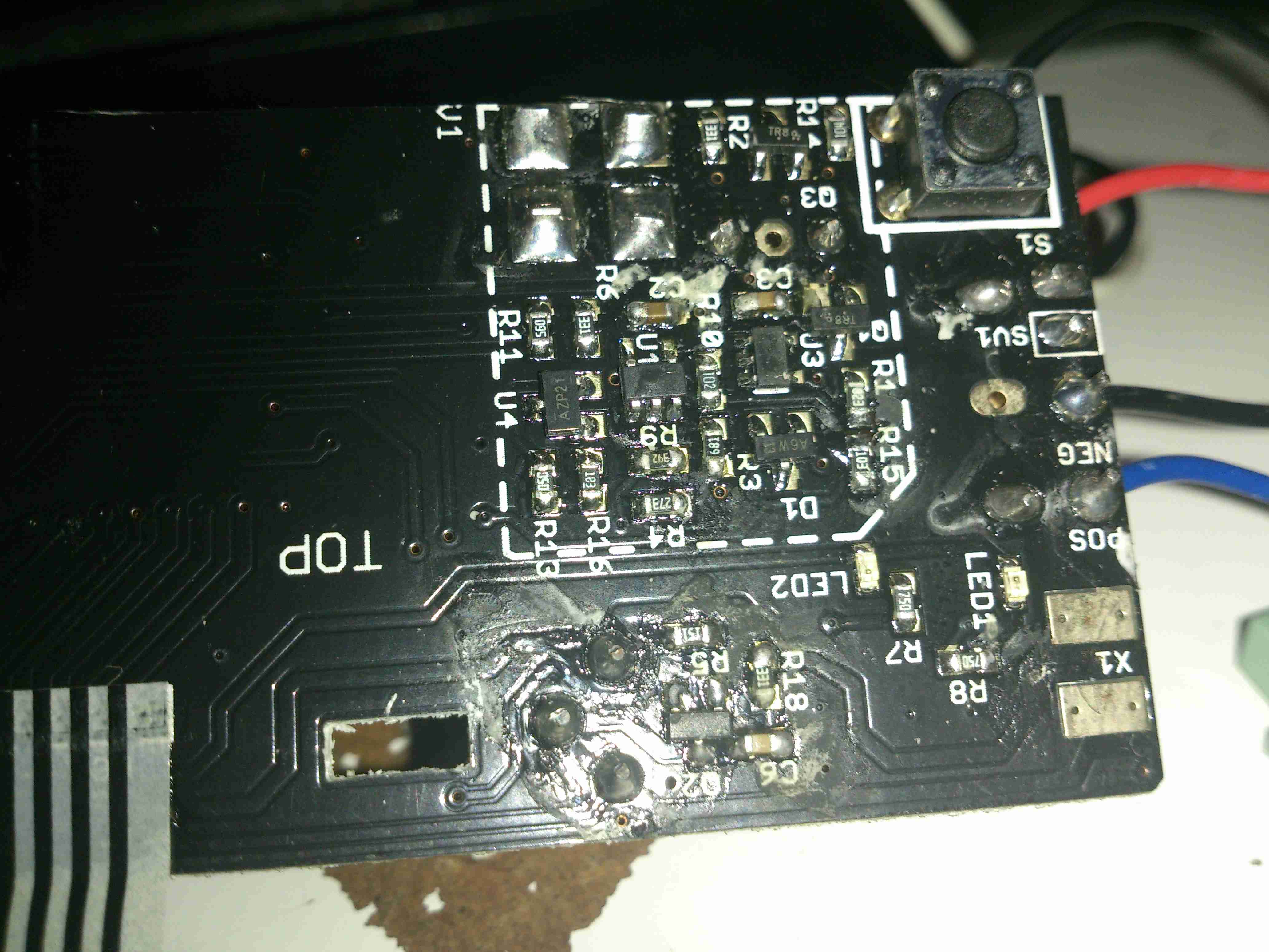
Sensor Front End Amplifier
Here’s a closer look at the front end for the CO sensor cell itself. I haven’t been able to decode the SMT markings on the SOT packages, but I’m guessing that there’s a pair of OpAmps & a voltage reference.
Compressed air is a rather useful power source, especially when all maintenance is done by the on board crew instead of by boatyards.
Screwfix had a good deal on a 50L 3.5CFM air compressor, to save space this has been permanently mounted in a free space & air will be piped to where it is needed from a central point.
Because of the total height of the machine, the compressor itself has been unbolted from the tank, a copper line connecting the two back together at a larger distance.
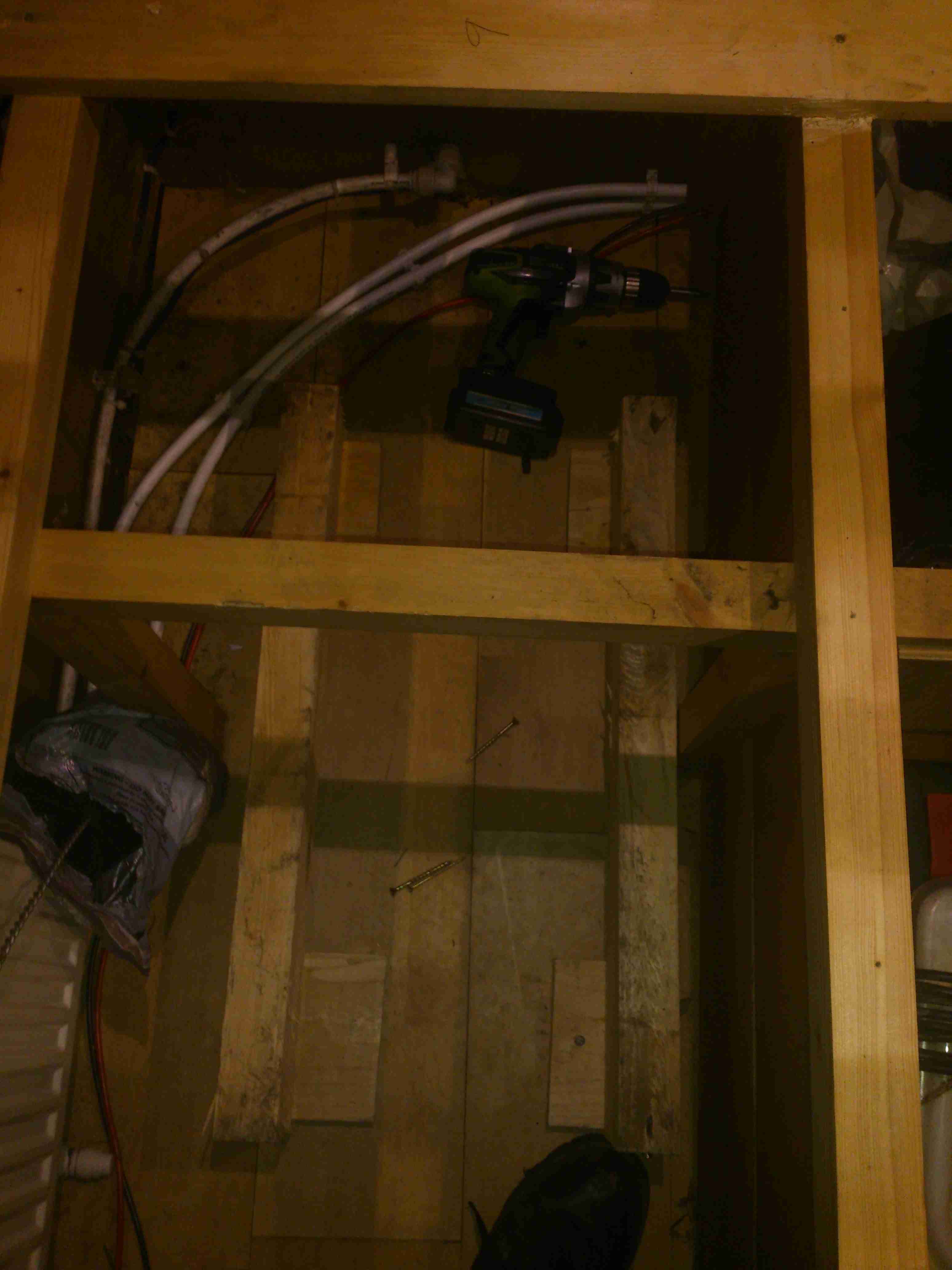
Bearers
In one of the very few free spaces available, under a bunk. A pair of timbers has been screwed to the floor to support the tank.
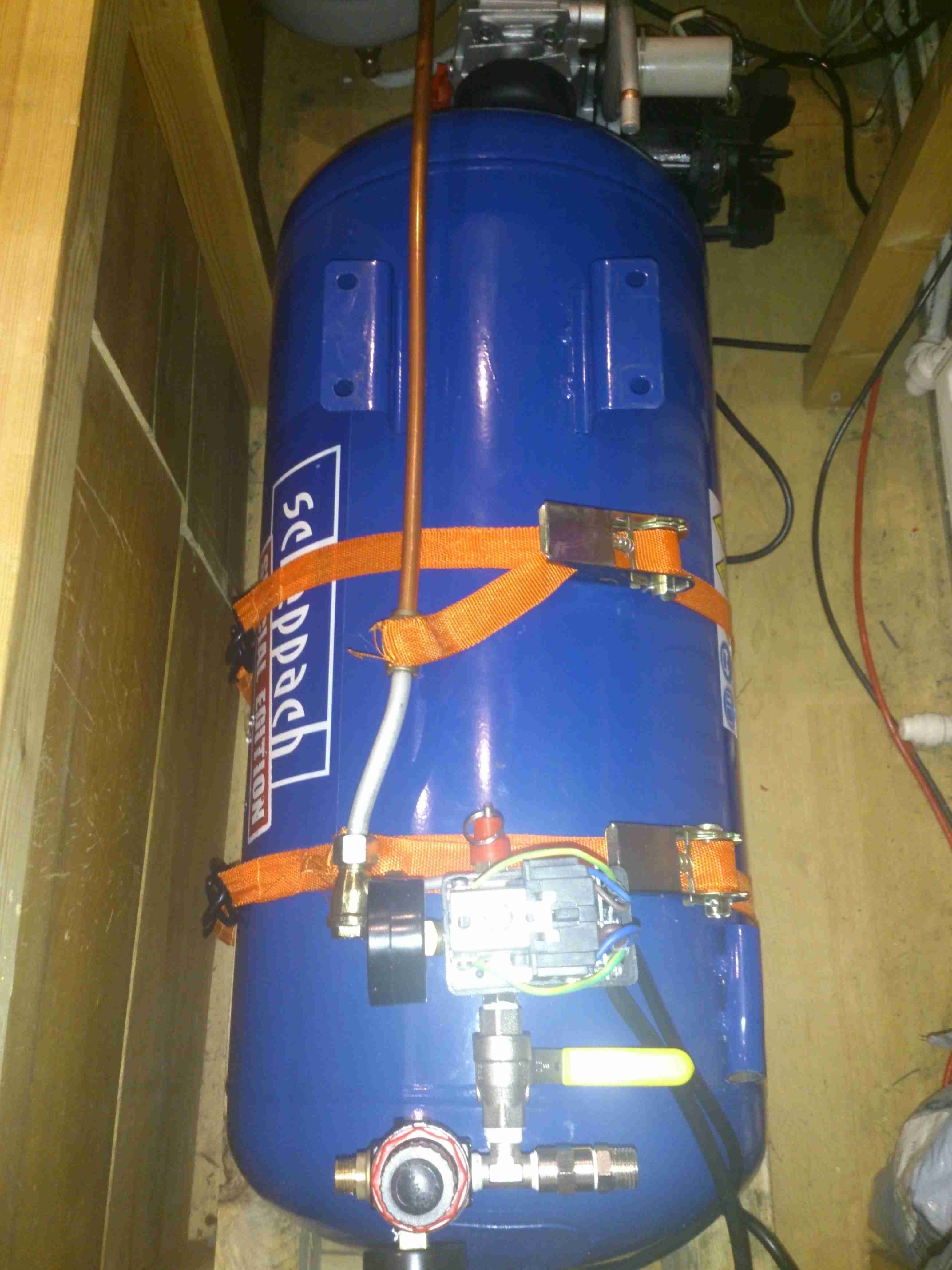
Tank Installed
The tank is strapped to the wooden supports with a pair of ratchet straps, the compressor itself can be seen just behind the tank. The copper line on the top of the tank is going back to be connected to the compressor outlet.
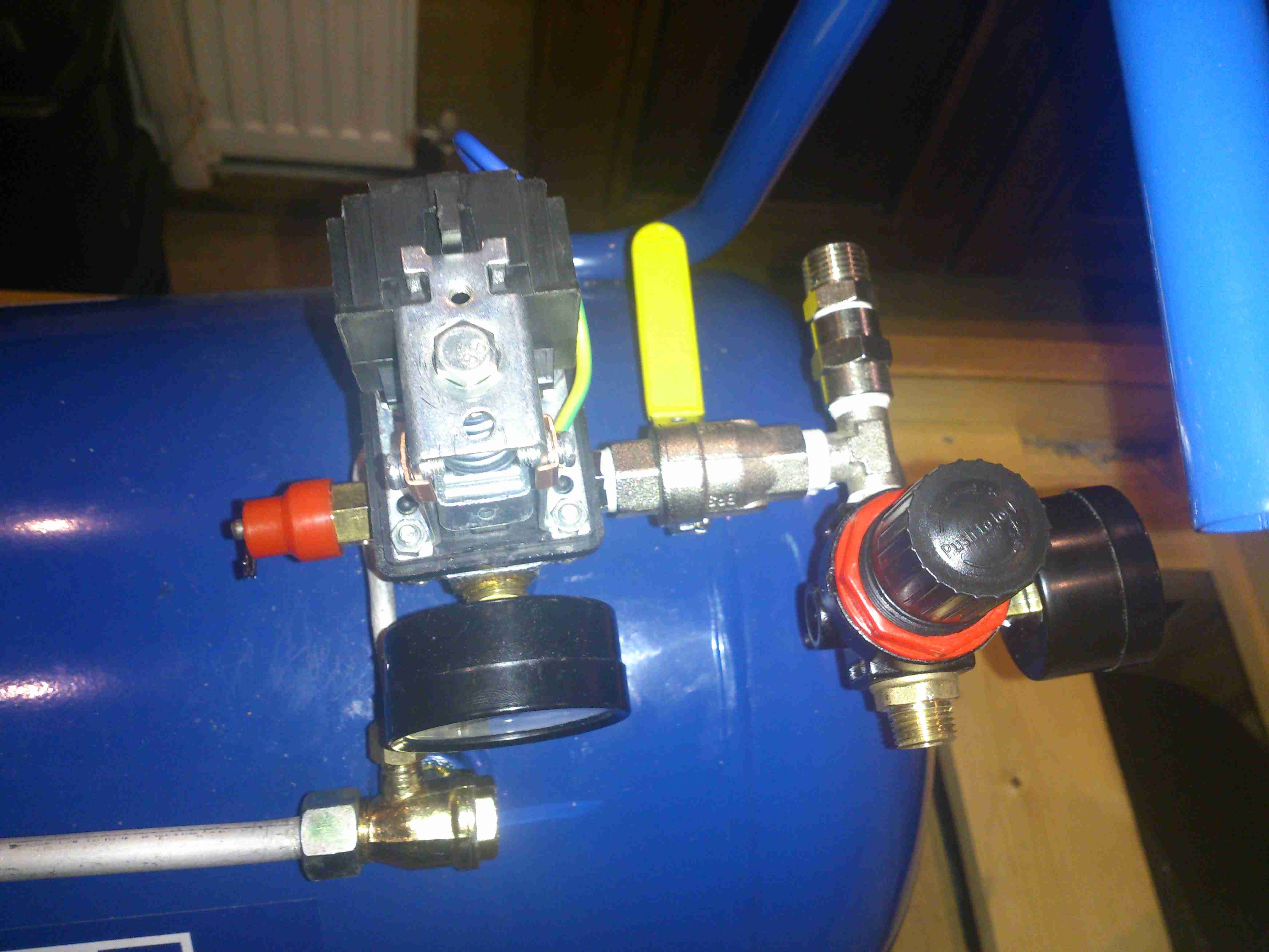
Air Fittings
Compressor control remains on top of the tank, the pressure switch & relief valve centre. After an isolation valve, the feed splits, the regulator installed will be feeding the air horn with 20PSI, replacing the existing automotive-style 12v air pump. The currently open fitting will be routed to a quick connect on the bulkhead. This will be accessible from the front deck, an air hose can be fitted to get a supply anywhere on board.
More to come when the rest of the system gets installed!
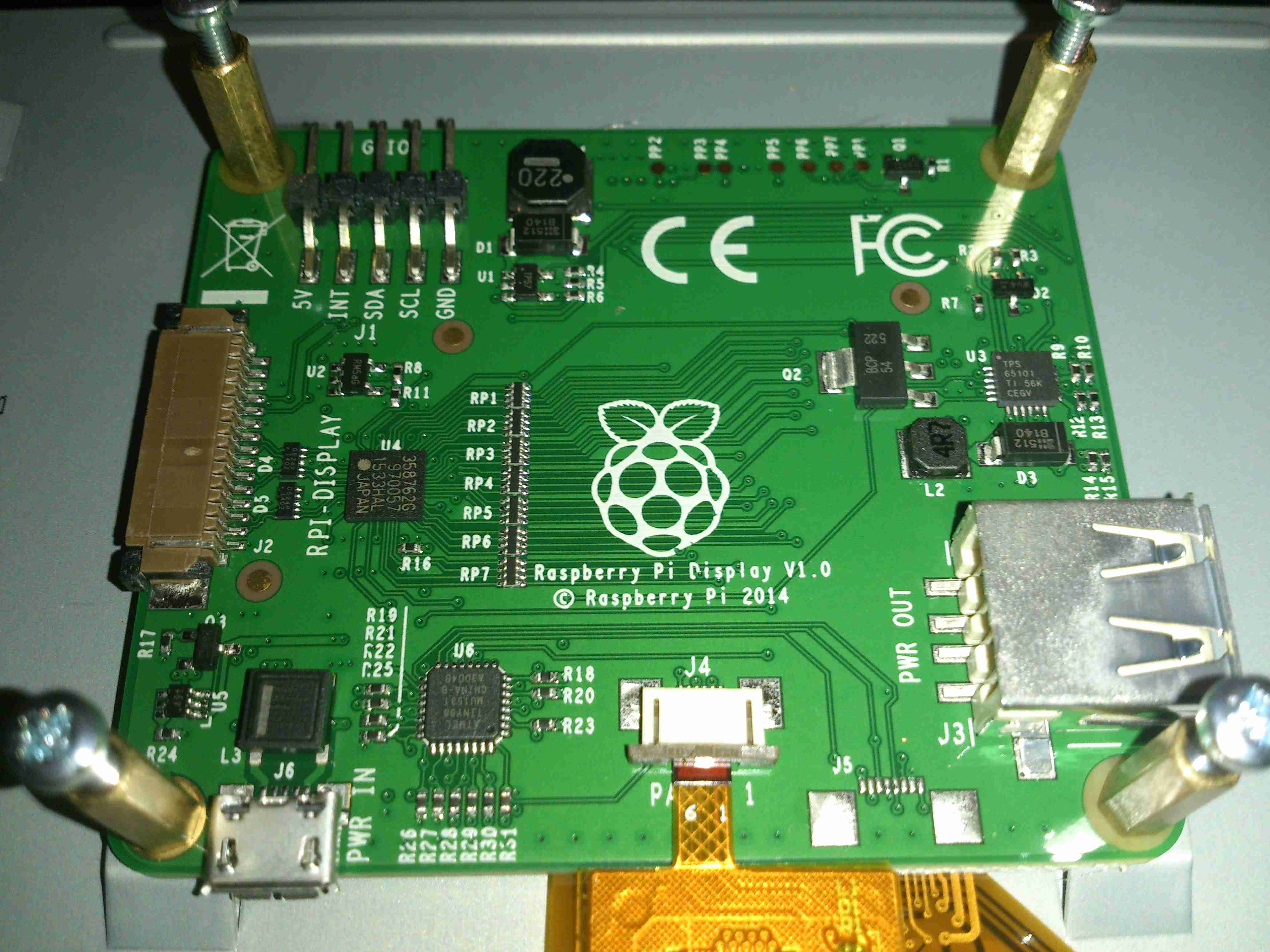
Finally the Raspberry Pi Foundation have released an official LCD for the DSI connector on the Pi. When these were announced, I placed an order straight away, but due to demand it’s taken quite a while for it to arrive in the post.
Interface PCB
The LCD itself is an RGB panel, to interface the Pi via the MIPI DSI port, some signal conversion is required. A small PCB is mounted on the back of the LCD to do this conversion. It also handles the power supply rails required by the LCD itself & interfacing the touch screen.
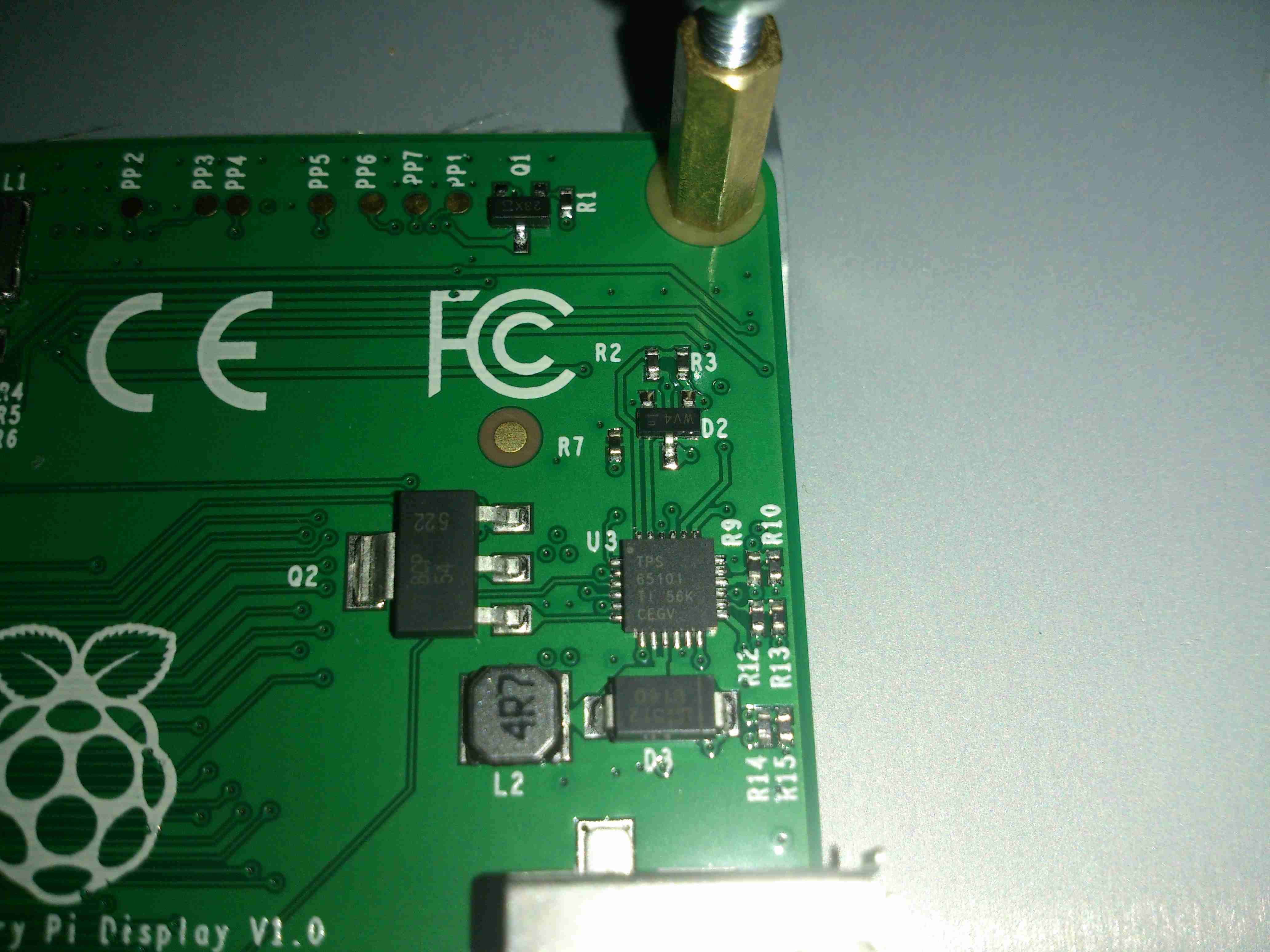
LCD Power Supply
Taking care of the power supply is a Texas Instruments TPS65101 triple output LCD power supply IC. This also has a built in linear regulator to supply 3.3v for the rest of the circuitry on board. The large transistor to the left of the IC is the pass transistor for this regulator.
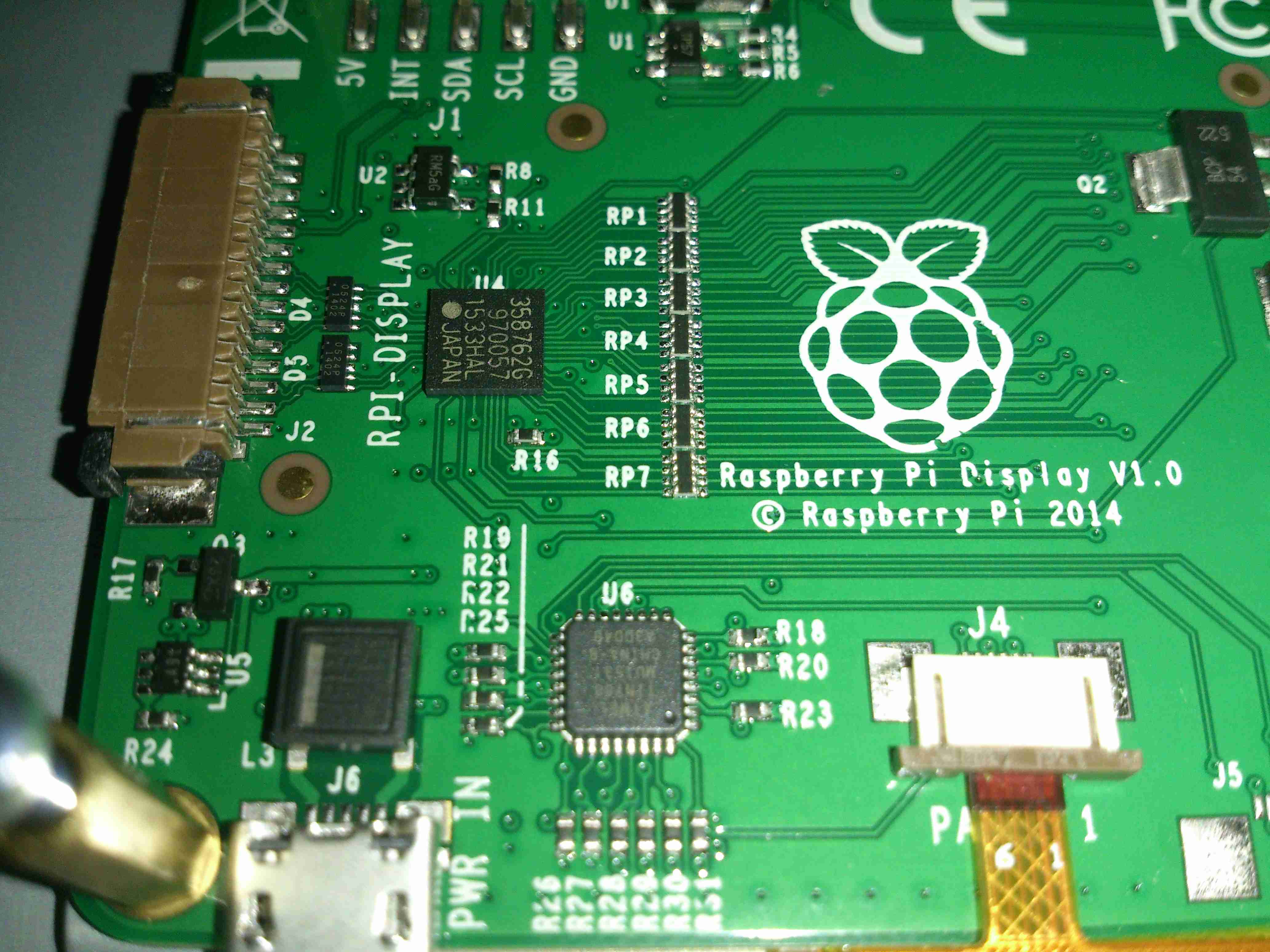
Main Controller
The video signal comes in on the FFC connector on the left, into the BGA IC. I’ve not managed to identify this component, but it’s doing the conversion from serial video from the Pi to parallel RGB for the LCD.
There’s also an Atmel ATtiny88 on the board below the main video conversion IC, not sure what this is doing.
The touch controller itself is mounted on the flex of the LCD, in this case it’s a FT5406.
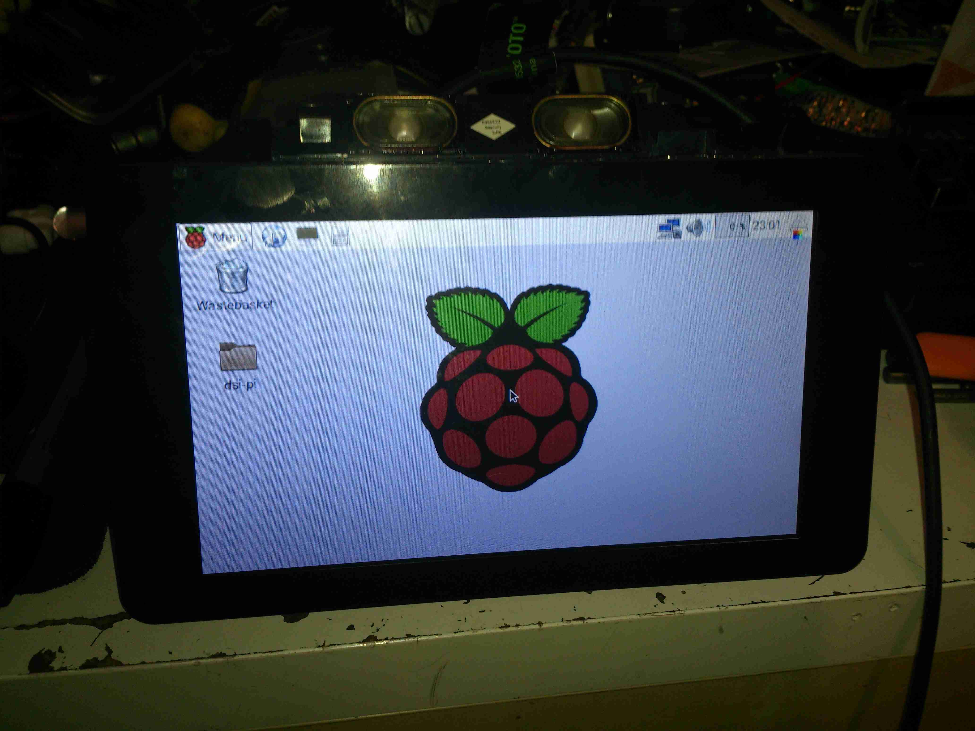
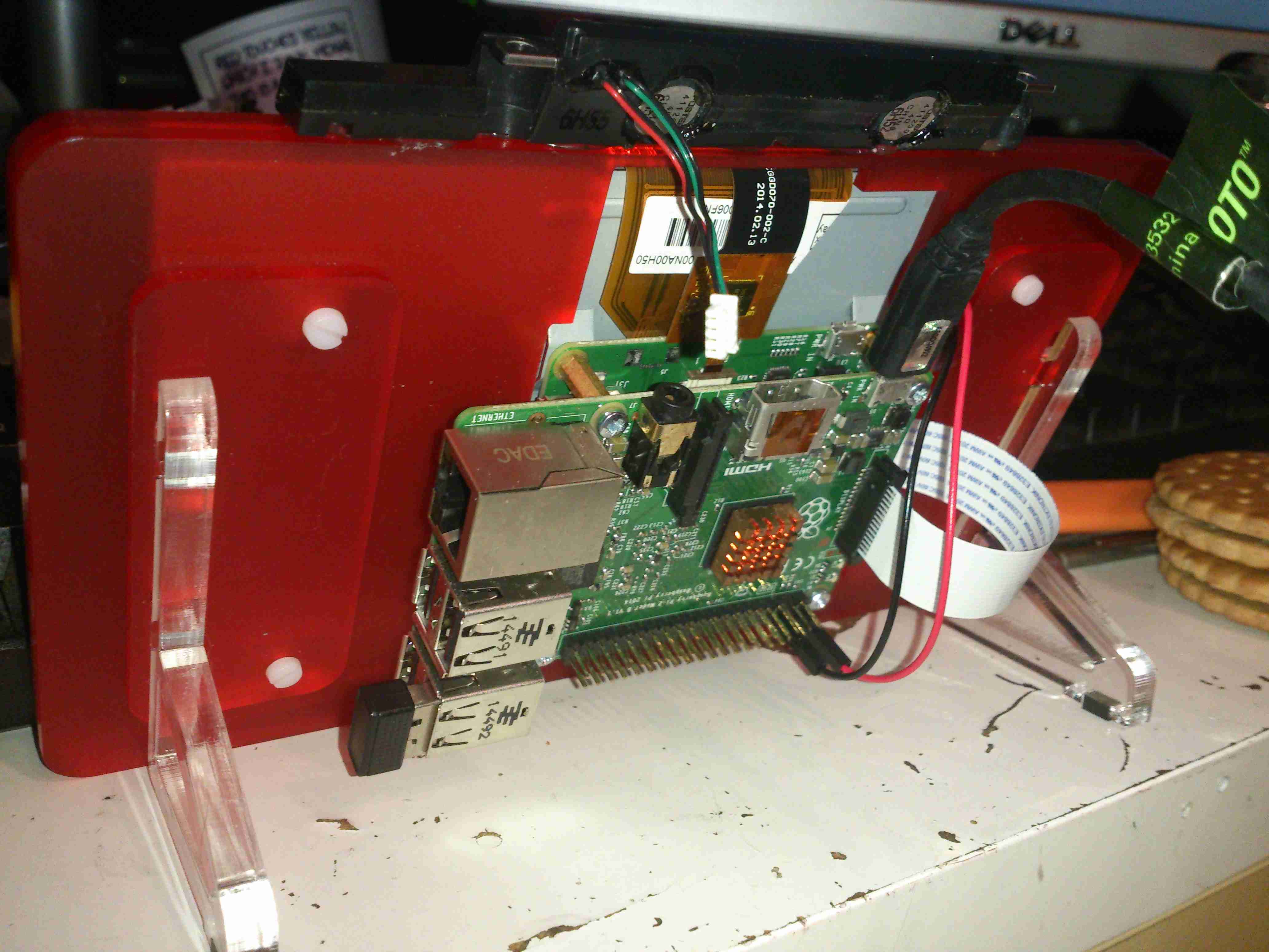
Raspberry Pi LCD
Here’s the LCD in operation. It’s not the highest resolution out there, but it leaves the GPIO & HDMI ports free for other uses.
Pi Mounted
The Pi screws to the back of the LCD & is connected with a flat flex cable & a pair of power jumpers. I’ve added a couple of small speakers to the top edge of the LCD to provide sound. (More to come on this bit).
To help improve the privacy of my blog readers, I’ve now enabled SSL support, with help from the guys over at Let’s Encrypt, supplying a free certificate.
Since Let’s Encrypt is still in closed beta, I won’t be forcing the use of SSL, but if you want to switch over to the SSL version of the site, click HERE!
It’s been a while since I’ve done a proper radio based post, so it’s a bit of a shame that I have to start off with a rant, but it’s required in this case.
One of the local 70cm repeaters, GB3WP seems to have many problems. The largest one seems to be G6YRK, the repeater keeper.
I had heard rumours of the repeater suddenly going off air getting switched off when either an M3/M6 or 2E0/2E1 was using it. At the time I thought no fellow ham could be quite that petty.
What callsign I or anybody else has should not make a shred of difference whether we should be allowed on the air or not. I personally keep my operating standards as high as possible, way above and beyond what Ofcom stipulates in the licence terms, as it’s part of making the hobby enjoyable for everyone. Seems that not everyone feels the same (in my experience, the older generation of hams, some of whom believe that the tests these days are far too easy, etc, etc).
Then I got proved wrong.
I was doing some handheld radio testing with M3HHY over at Distant Signal Radio on GB3WP, as at the time GB3MR was having some issues with the local pirate (see my previous posts for more info on that prat).
Within a couple of minutes of us establishing a QSO, the repeater suddenly stopped responding. After trying to get back in for a good 15 minutes, it came back on air again.
The instant we gave our callsigns, off it went, into the ether. No response.
This behaviour continued for nearly an hour, and after trying to contact YRK directly, we gave it up as a bad job, with quite a bit of pissed off added into the mix.
If I’d not heard stories of the repeater being turned off when the “wrong people” are using it, I might have put it down to dodgy repeater equipment, but even that didn’t make sense, as it had a definite pattern.
We both fired off an email to the Repeater Keeper, only to get no response from that either (surprise, surprise).
That was the last time I personally attempted to make use of GB3WP.
Until I was given an audio clip of G6YRK in action this evening.
Seems that not even M0 calls are immune from being wiped off the air by GB3WP. Chris, M0OGG, has apparently also had this issue with the repeater. Lucky for him, he had the opportunity to speak to the keeper directly about what went on.
Here’s the audio, I’ll pick each part out & go into a few opinions/observations below.
So, Chris (M0OGG) has asked a simple question, and been met with hostility. Dick Move Number 1.
YRK is clearly reluctant to go into “detail” on the air. Probably because he’s talking complete shite. Only when Lewis (M3HHY) joins in with a slightly more defensive tone does Steve (G6YRK) actually say what Chris has been “reported” for.
After all that it seems that an accusation of keying over other repeater users is the bullshit line of the day. (For the record, I know Chris, he’s not the type of person to key over another radio user, that behaviour in of itself is idiotic).
Apparently he has witnesses to this action, and he’s insisting that others were also involved. Not to mention the fact that RDF has been done on (I’m assuming) all of these “offenders”. G6YRK must have quite the army of hams with lots of spare time.
I’m not sure who the other station is, as he doesn’t give a callsign.
As Lewis jumps in & comments, the Repeater Keeper should be saying something to users he suspects of this kind of thing, in my opinion.
The real reason, of course, that he keeps turning the repeater off when others are using it is that he’s a passive-aggressive vindictive moron.
Surprise, surprise, he can’t remember the “exact date”, (because it never actually happened), it’s just “the other day, somebody did it”. Yeah, great evidence there Steve, because apparently the only person around at the time was Chris. How can he know this? When a repeater has a coverage area as wide as GB3WP, this guy is claiming that he knows that only a single person is listening? No, I think it’s bullshit too.
GB3WP Coverage Map
For reference, here’s the coverage map of the repeater. Steve G6YRK must be bloody psychic to make such a comment.
He then mentions a “friend” of Chris, but again refuses to give any names. Again I’m calling bullshit.
Swifty following this he goes into full kick-my-toys-out-of-the-pram mode because he’s been openly challenged.
While he’s correct in his statement that he can do as he pleases with the repeater, it’s not very good form to just switch the thing off when licenced users are having a perfectly valid QSO. If he doesn’t like people using the repeater, he should turn it off permanently & remove the listing from the repeater group.
After this, Steve makes the comment that he knows nothing of the repeater going off, as he’s been out all night. He mentions his Repeater Stasi again, and then makes a partial retraction of his previous statement, now that it “might” not have been Chris previously. Well Steve, we’re finally getting towards something that resembles truth. You’ve got absolutely no idea who is “keying people out”, if it’s even happening at all. So much for “having people all over the place” listening to where transmissions are coming from.
After Chris confronts him again, he returns to the fallback of that as the NoV holder it’s his prerogative to be able to switch the repeater off whenever he pleases.
When confronted with the fact that people pay into the repeater group to help keep them running, he claims that Chris’ signal is breaking up. My arse. Every other station on the repeater can hear him fine.
There’s probably more to add to this, so if I get any more relevant information from other sources I’ll add on to the saga.
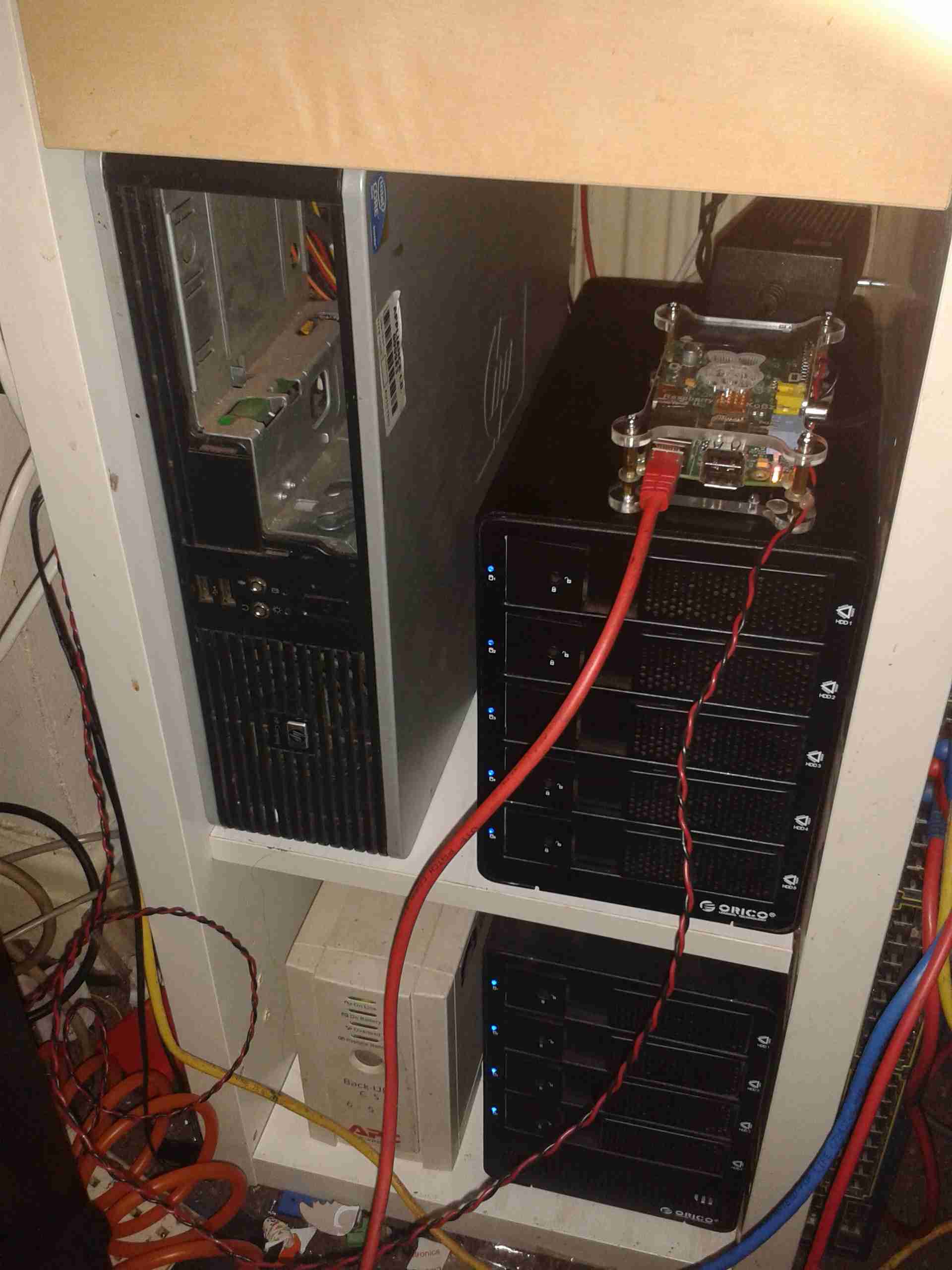
My main bulk storage for the home LAN is a bank of 4TB drives, set up in a large RAID6 array. Due to a brownout this evening on the +12v supply for one of the disk banks, I’ve had to start rebuilding two of the disks.
Core NAS
The total array size is 28TB after parity – 9 4TB disks in total. The disks are connected through USB3 to the file server.
mdadm Detail
Here’s the current status of the array. Two of the disks decided that they wouldn’t rejoin the array, so they got their superblocks cleared & readded manually. This forced the array into rebuilding.
Rebuild Progress
Rebuilding an array of this size takes a while, as can be seen from the image above, it’s going to take about 7200 minutes, or 5.2 days.
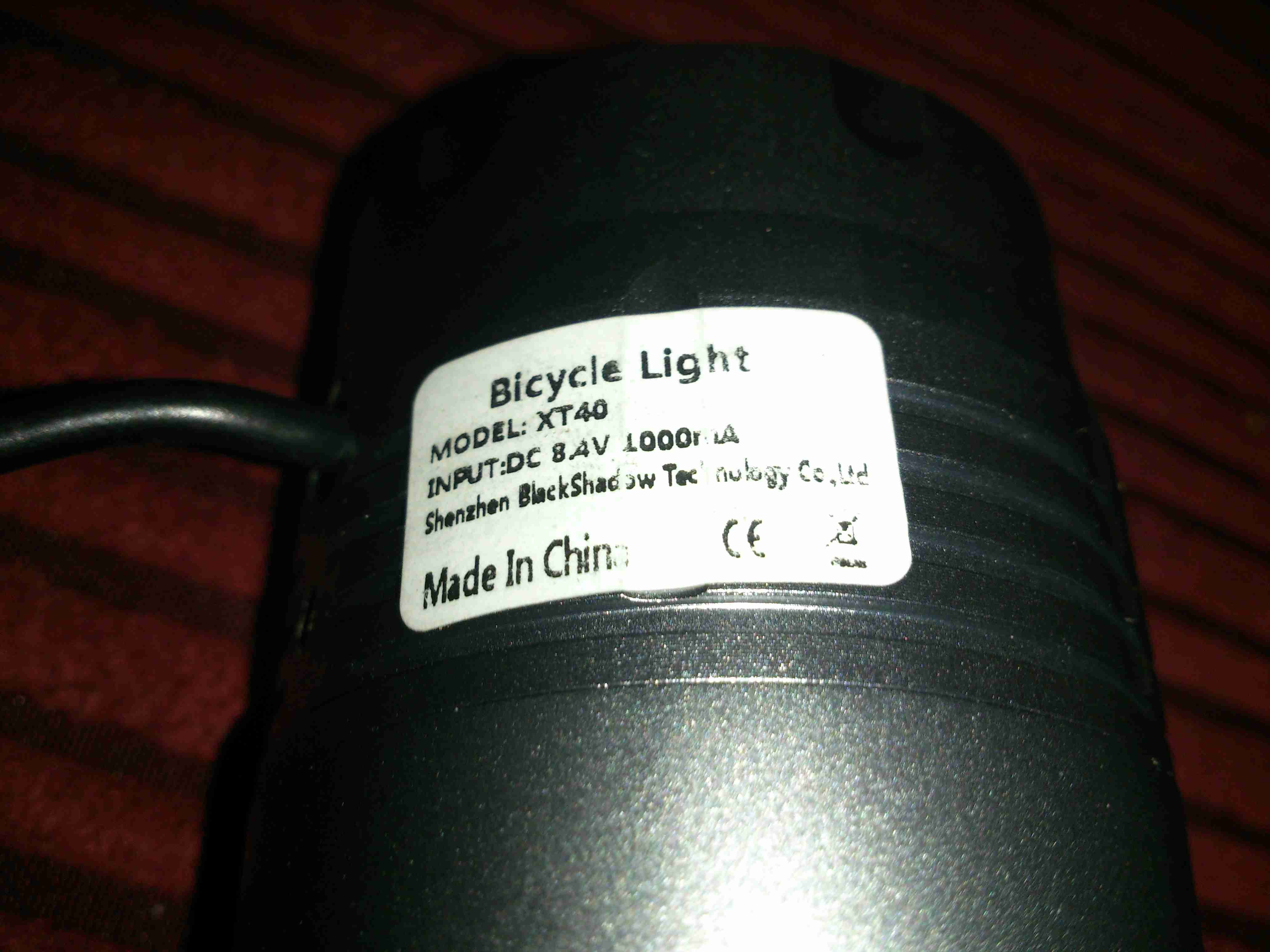
Here’s another torch from eBay, this time with 5 Cree XML-T6 LEDs.
Label
Having 5 Cree LEDs rated at up to 3A a piece, this light has the capacity to draw about 50W from it’s power supply. In this case though, current draw is about 1.5A at 12v input on the full brightness setting.
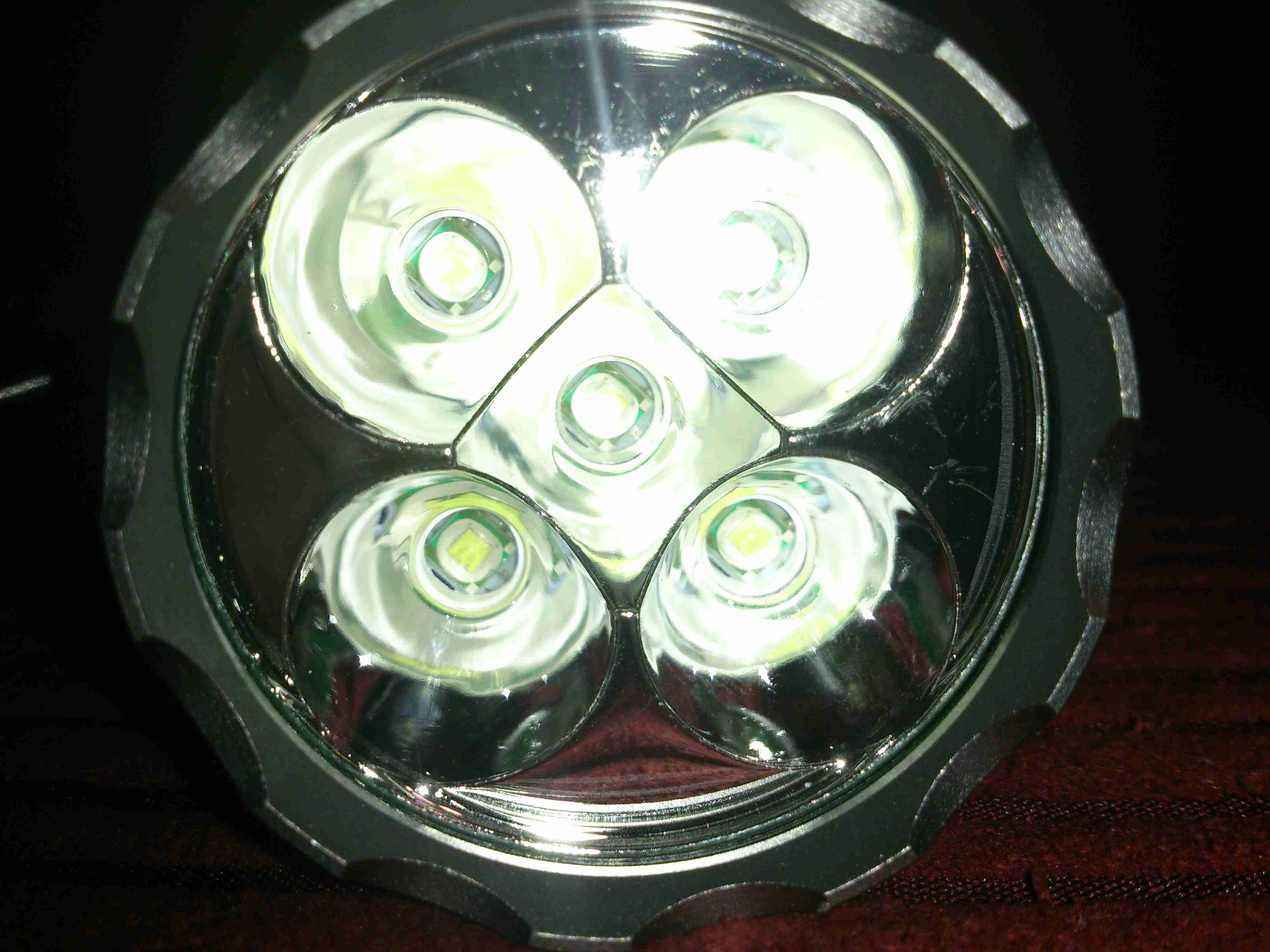
Cree LED Torch
Here’s the LEDs mounted into the reflector. Fitting this many high power LEDs into a small space requires some serious heatsinking. The casing is made of machined aluminium.
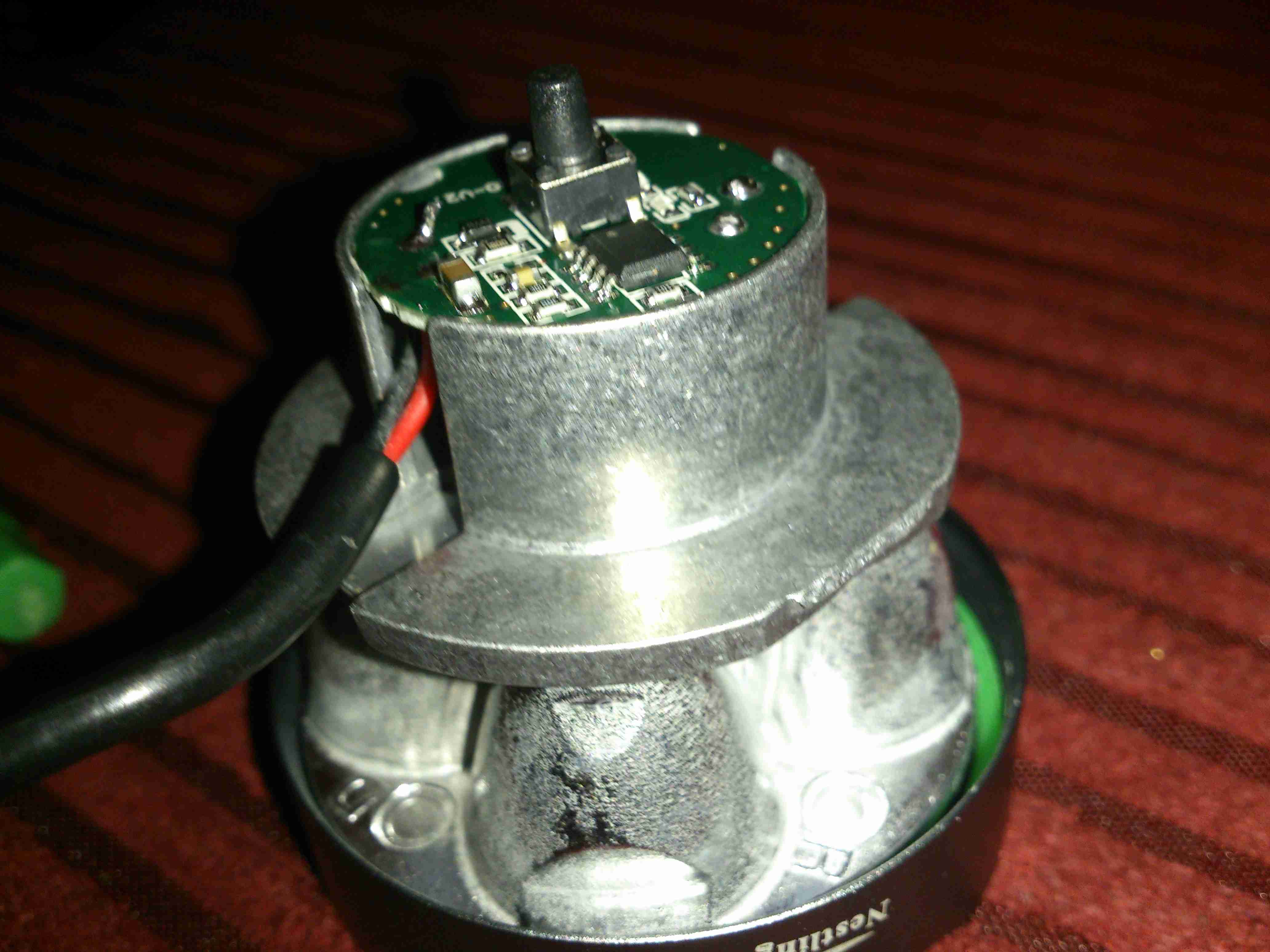
LED Module
Unscrewing the front bezel allows the internals to come out. The core frame & reflector is all cast alloy as well, for heatsinking the LEDs. The controller PCB is mounted into a recess in the back of the LED mount.
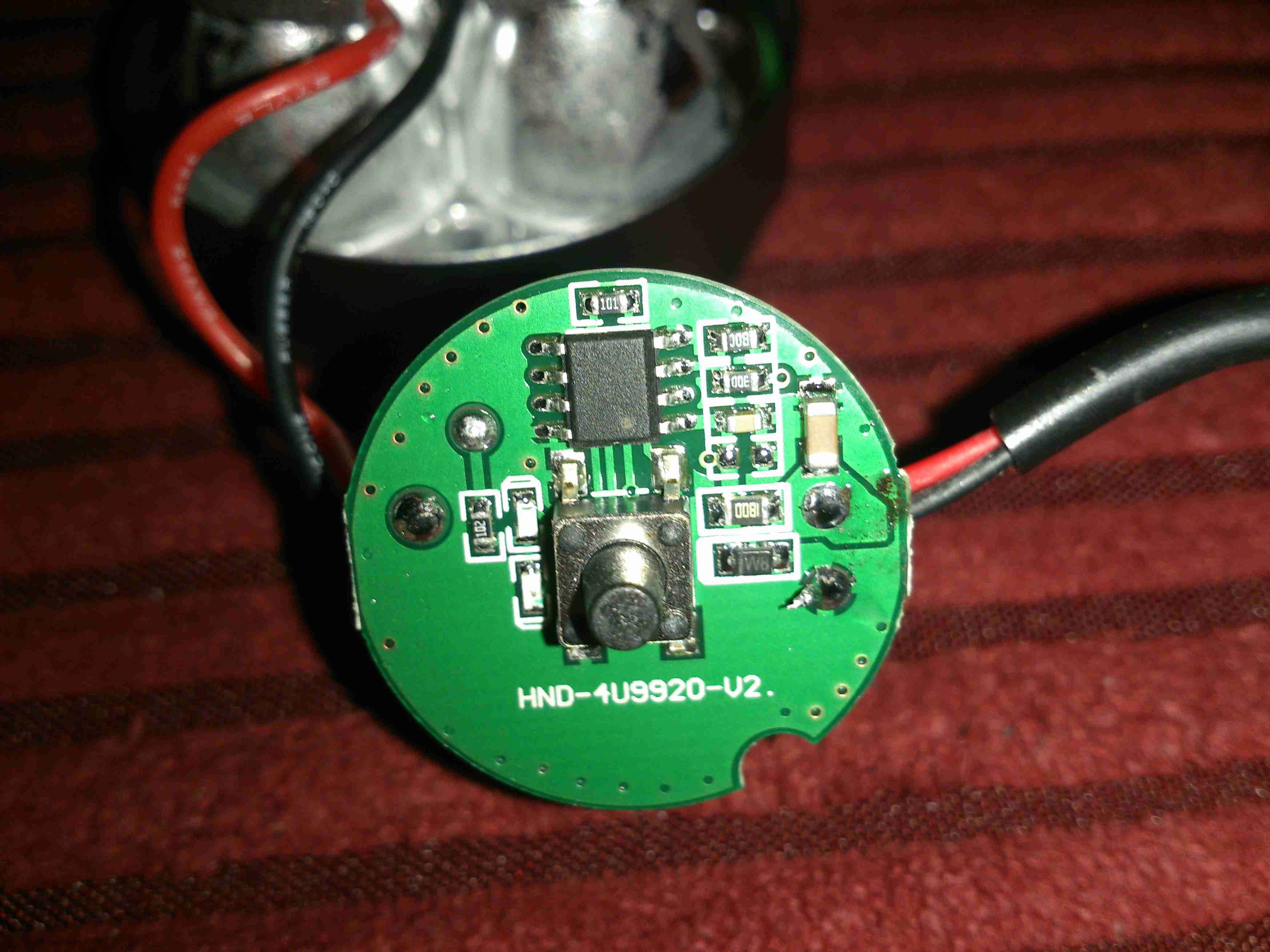
Controller
Here’s the controller itself. The usual small microcontroller is present, for the multiple modes, and handling the momentary power switch.
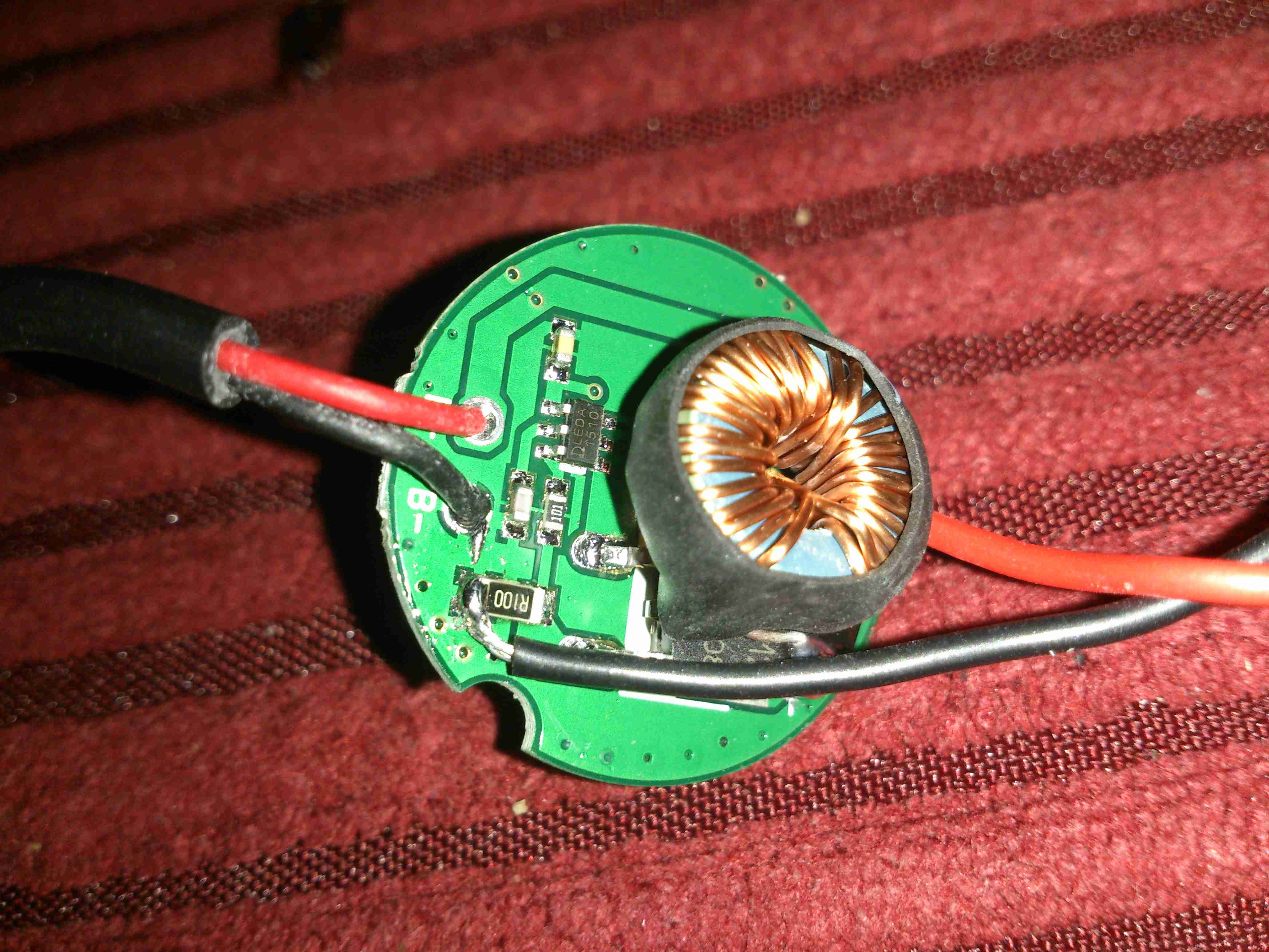
Switching Inductor
As all the LEDs on this torch are connected in series, their forward voltage is ~12-15v. The battery is an 8.4v Li-Ion pack, so some boost conversion is required. This is handled by the circuitry on the other side of the board, with this large power inductor.
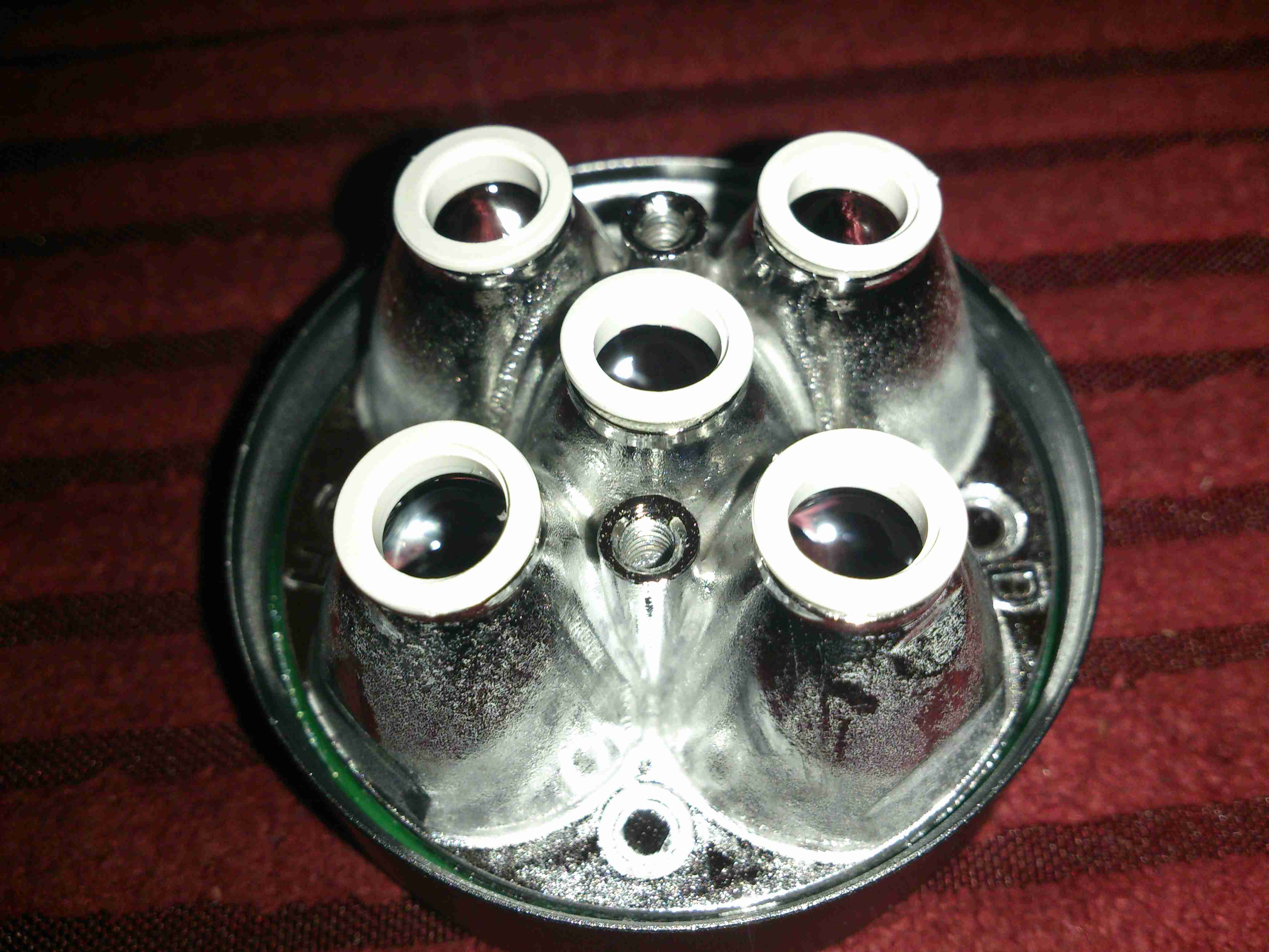
Reflector
The reflector screws onto the front of the LED array, centered in place with some plastic grommets around the LEDs themselves.
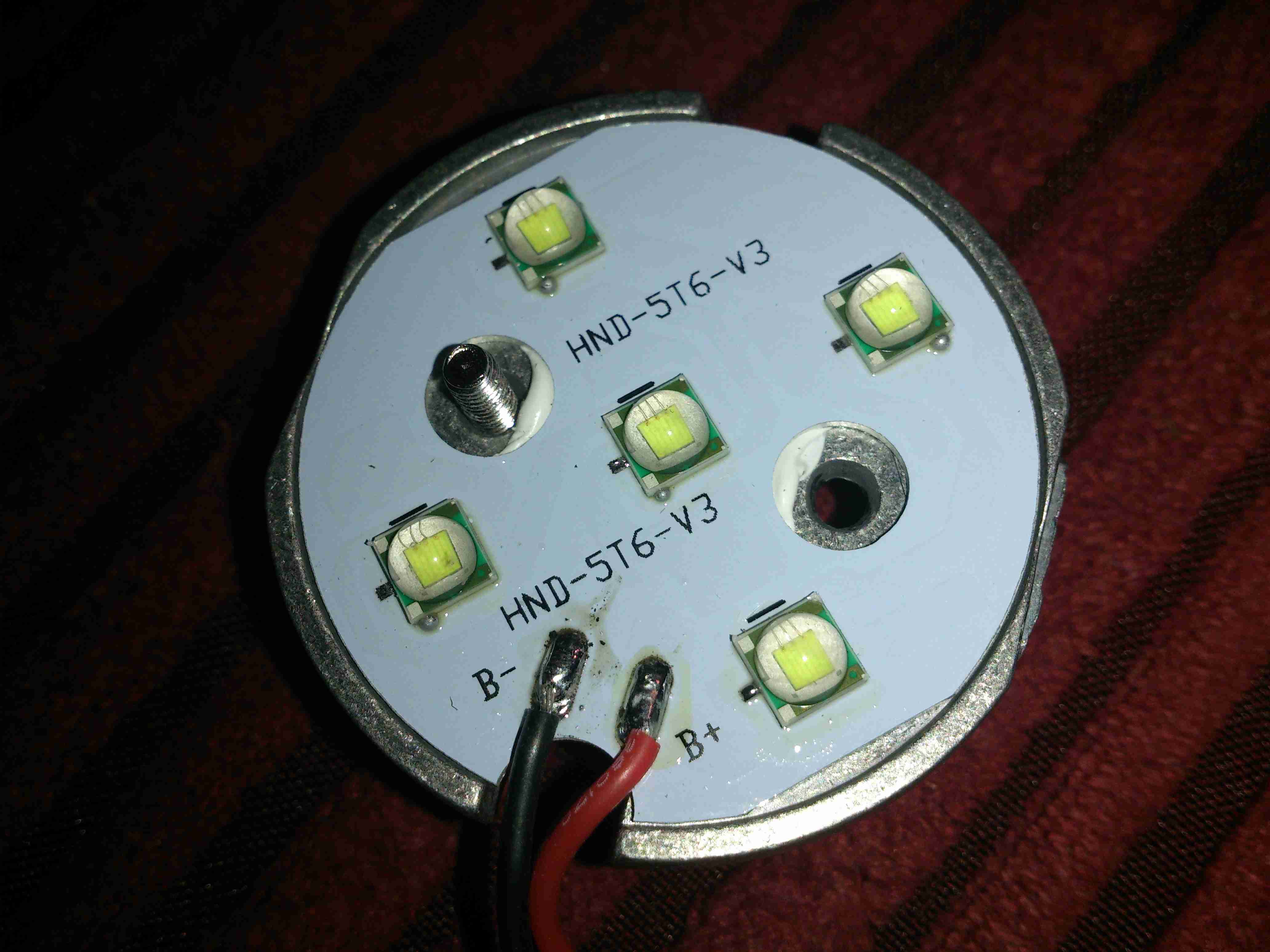
LED Array
Finally for the torch, the LED array itself. This is attached to the frame with some thermal adhesive, and the LEDs themselves are mounted on an aluminium-core PCB for better heat transfer.
This module unsurprisingly generates quite some heat, so I have improved the thermal transfer to the outer case with some thermal grease around the outer edge.
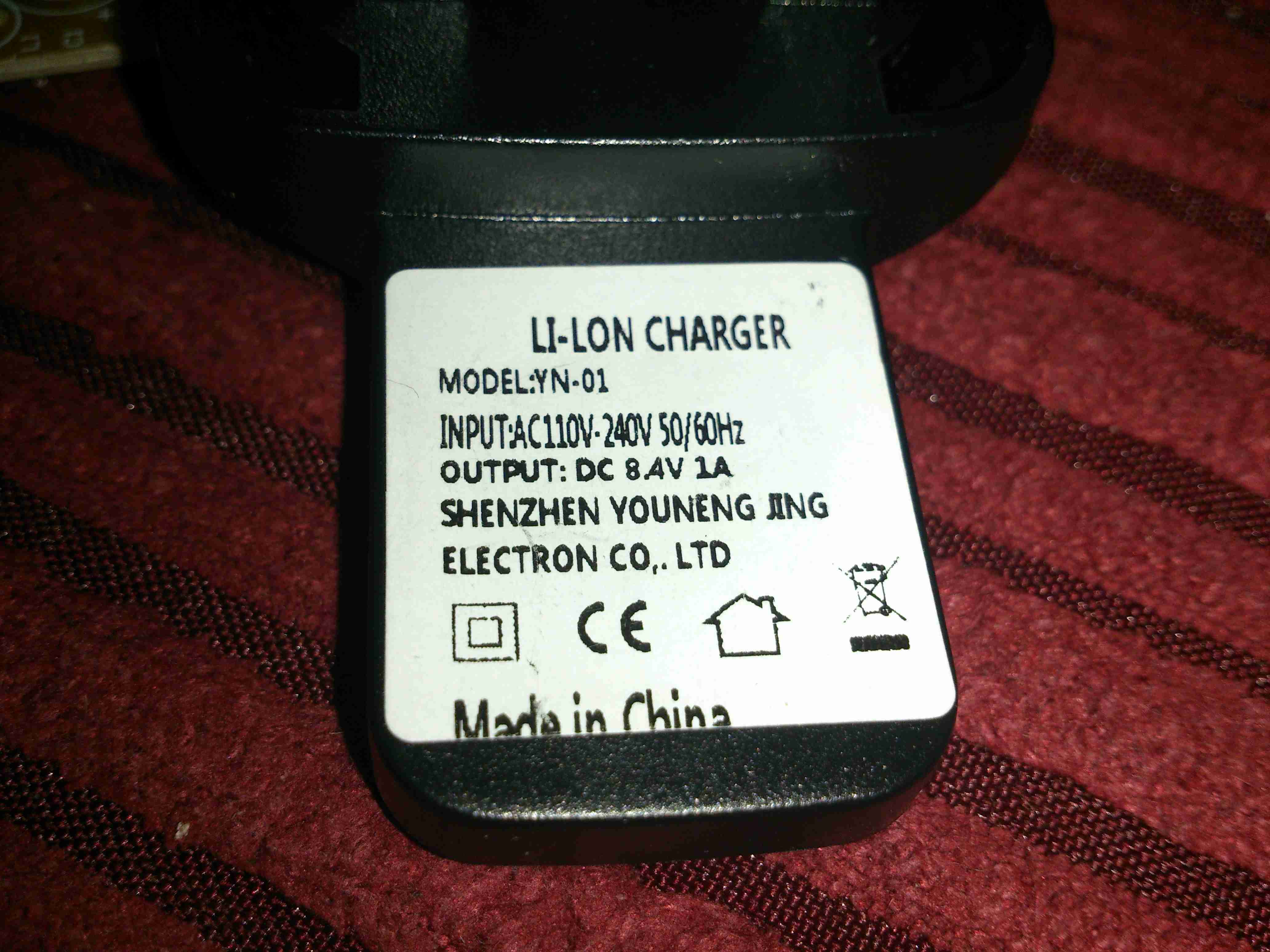
Charger
The supplied charger is the usual Chinese cheapy affair, claiming an output current of 1A at 8.4v. I never use these chargers, so they get butchered instead.
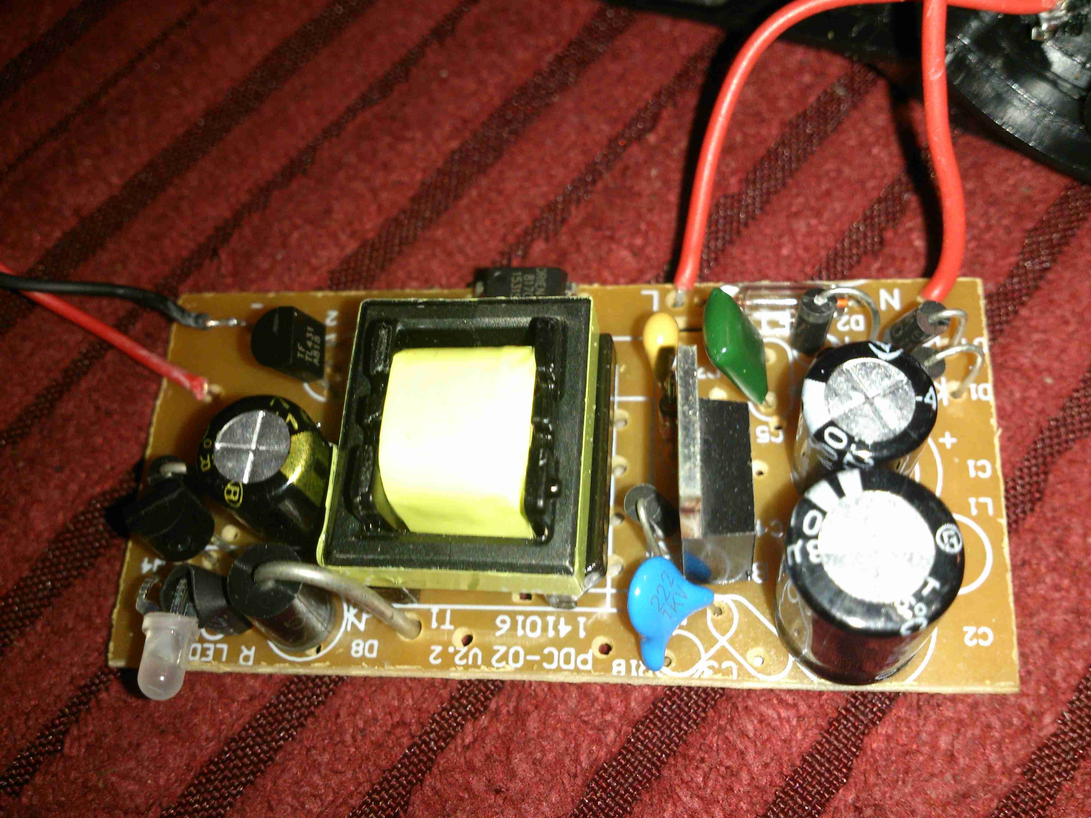
Charger PCB
Here’s the main PCB. Overall the construction isn’t that bad, the input mains is full-wave rectified, but there is little in the way of RFI filtering. The supply is fused, but with an absolutely tiny glass affair that I seriously doubt has the ability to clear a large fault current.
Like many cheap supplies, the output wiring is very thin, it’s capacity to carry 1A is questionable.
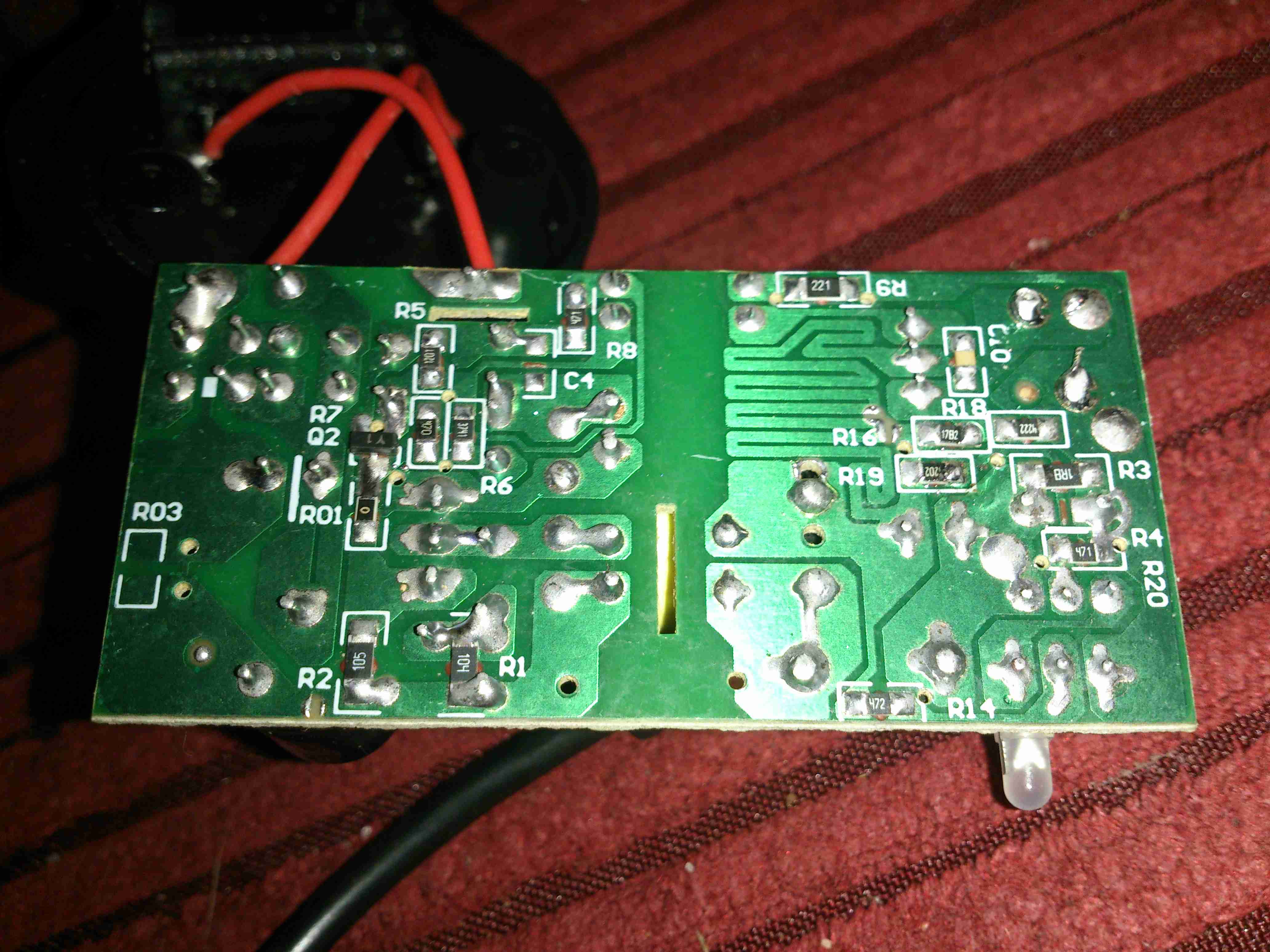
PCB Reverse
On the reverse side, there’s a nice large gap between the mains side & the low voltage output. There’s even an anti-tracking slot under the optoisolator.
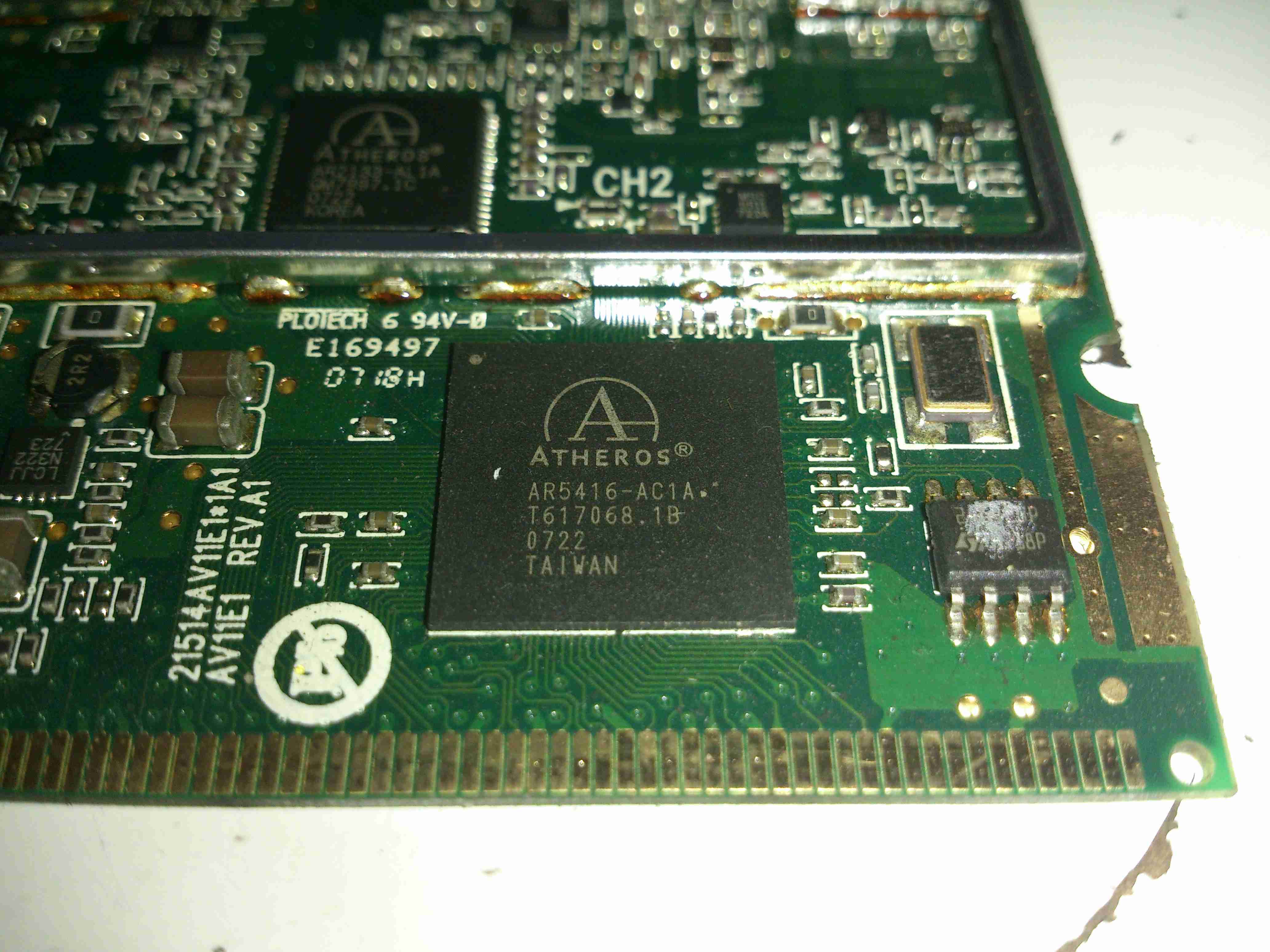
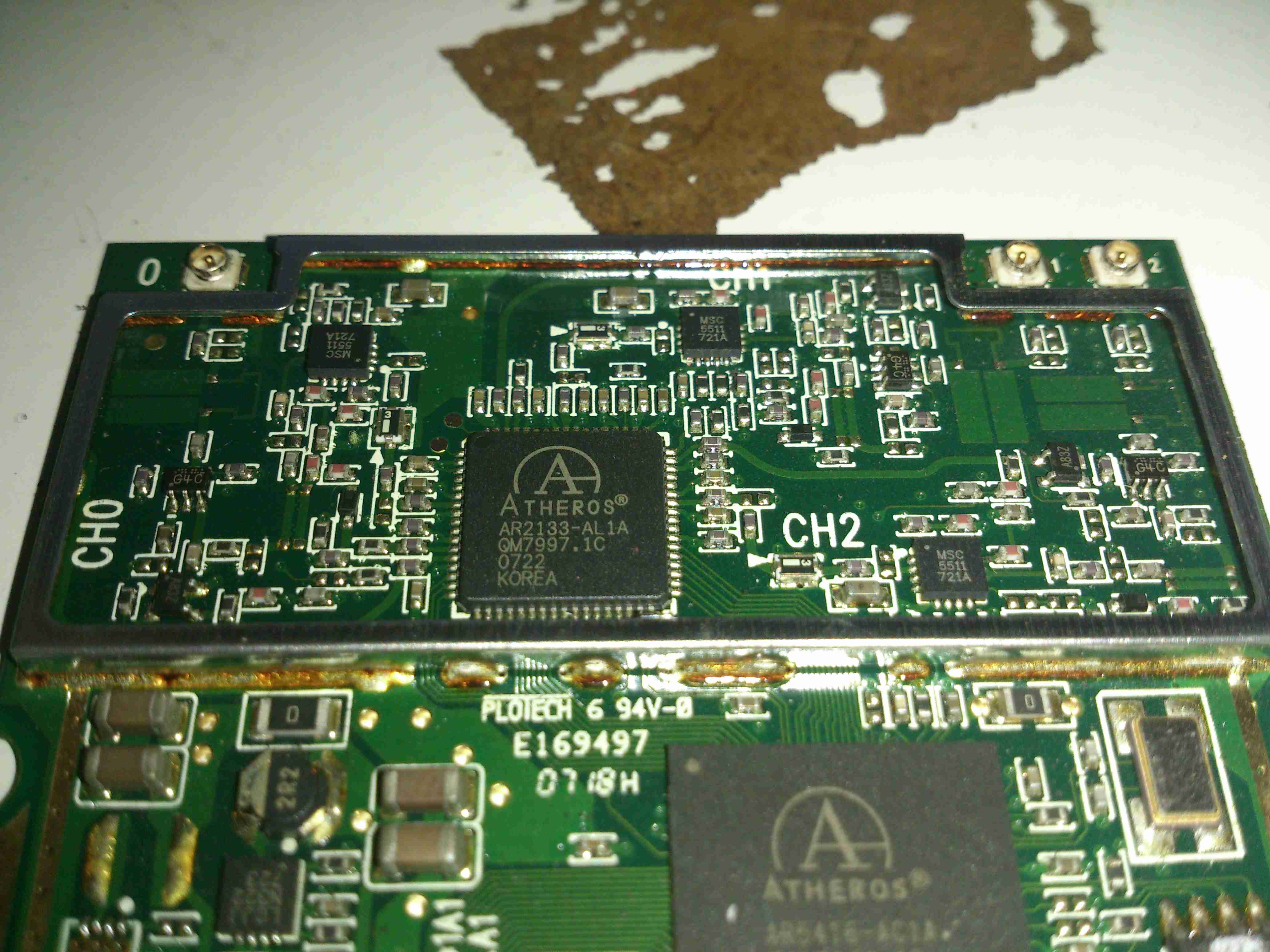
Here’s a quick look at one of the now surplus cards from my old networking system, a MiniPCI Wireless interface card.
Card Overview
This is an older generation card, one of the first with Wireless N support on 2.4GHz.
PCI Chipset
Network PHY & firmware EEPROM. Power supply stuff is over to the left.
RF Transceiver
Inside the shield is the RF Transceiver IC & it’s associated RF power amplifier ICs for each antenna. These power amplifiers are LX5511 types from Microsemi, with a maximum power output of +26dBm.
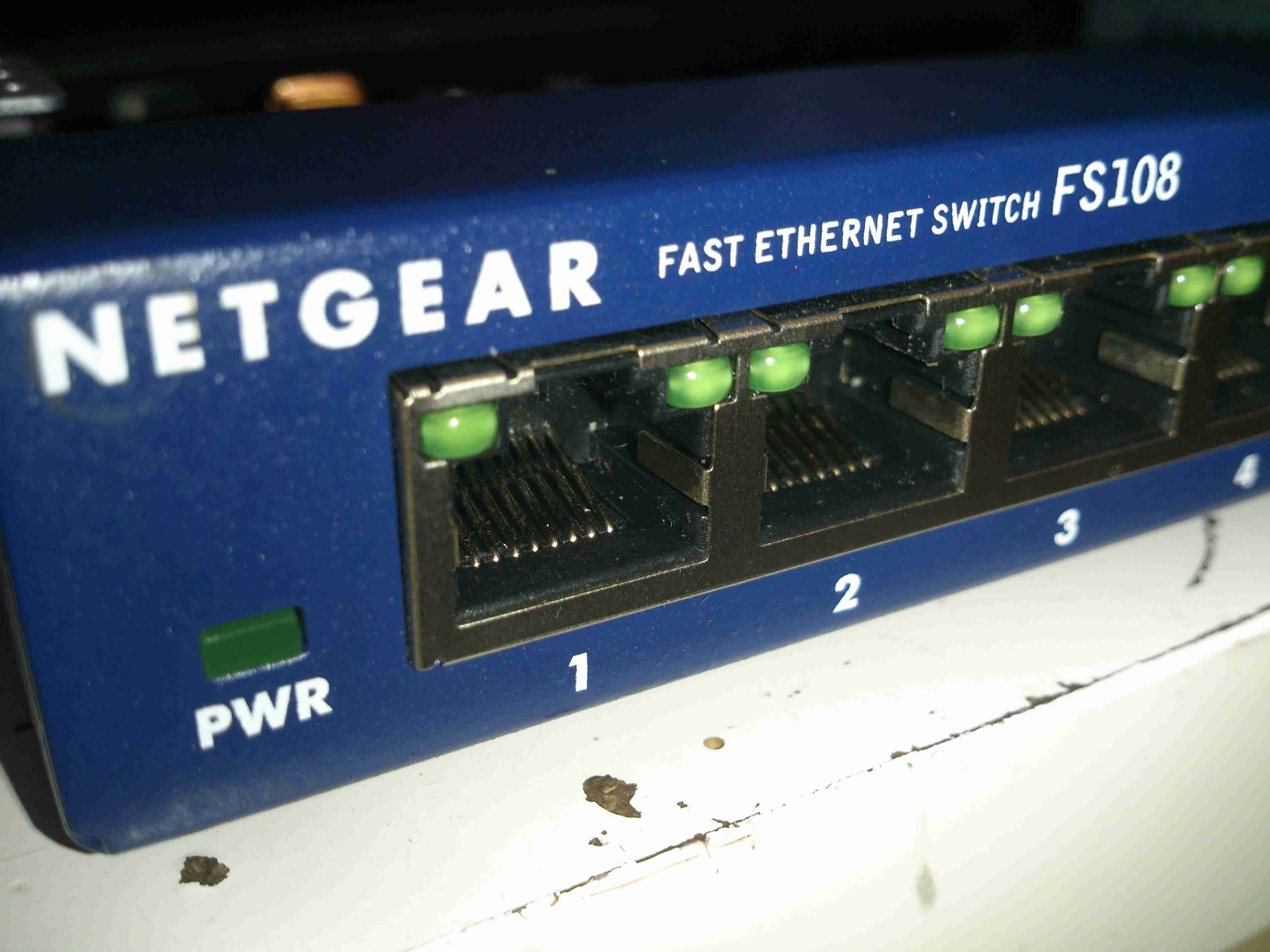
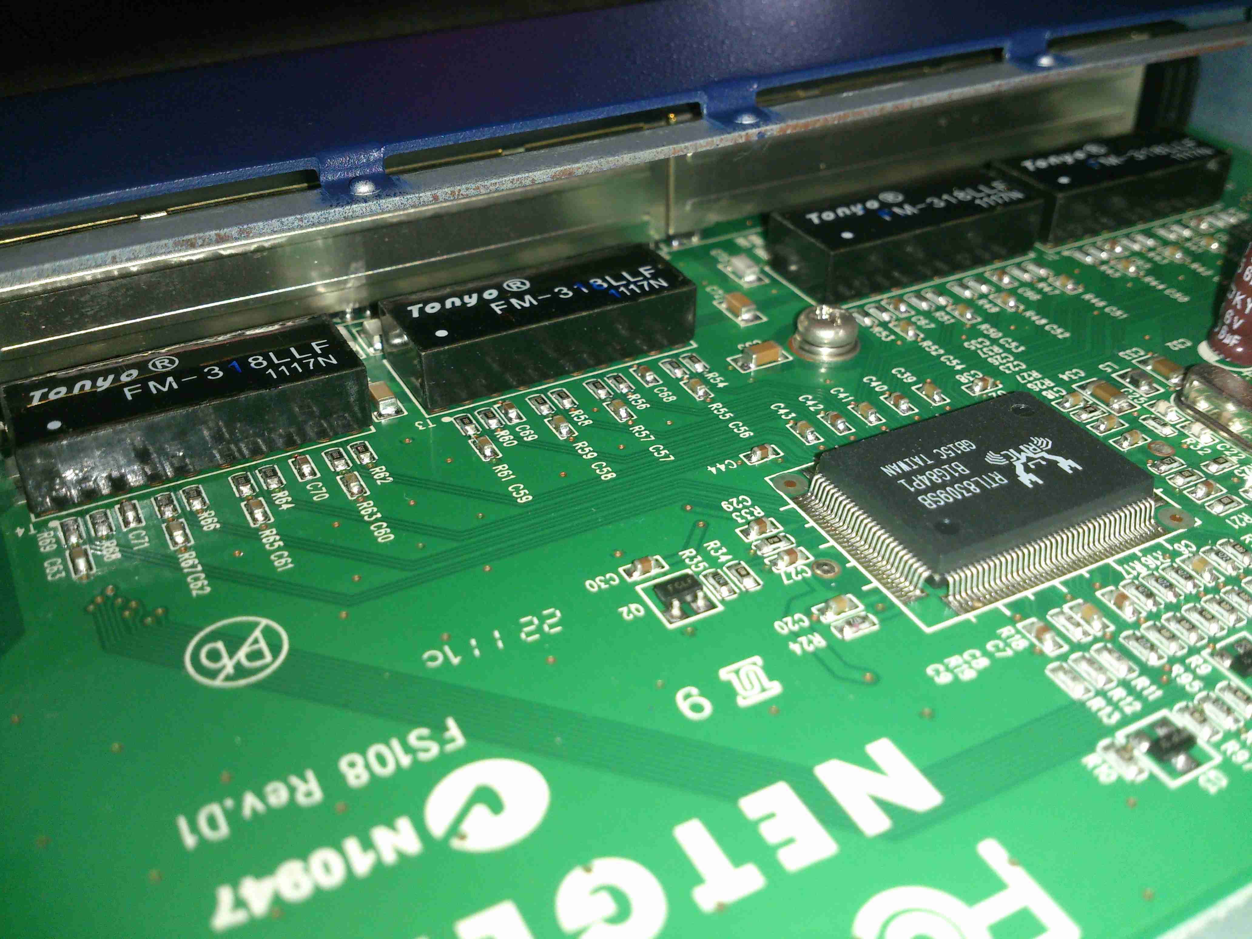
During the replacement of the networking onboard nb Tanya Louise with gigabit, the main 8-port distribution switch was also changed. Here’s a quick teardown of the old one.
Netgear FS108
This has been quite a reliable switch for the internal networking on board, but the time has come to switch over to something a little faster. This switch will be getting repurposed for the slower devices on my network, such as the radiation monitor & the raspberry Pi systems.
Cover Removed
Here’s the top removed from the switch. It’s a very simple construction, with a small power supply section & the main switch IC in the centre.
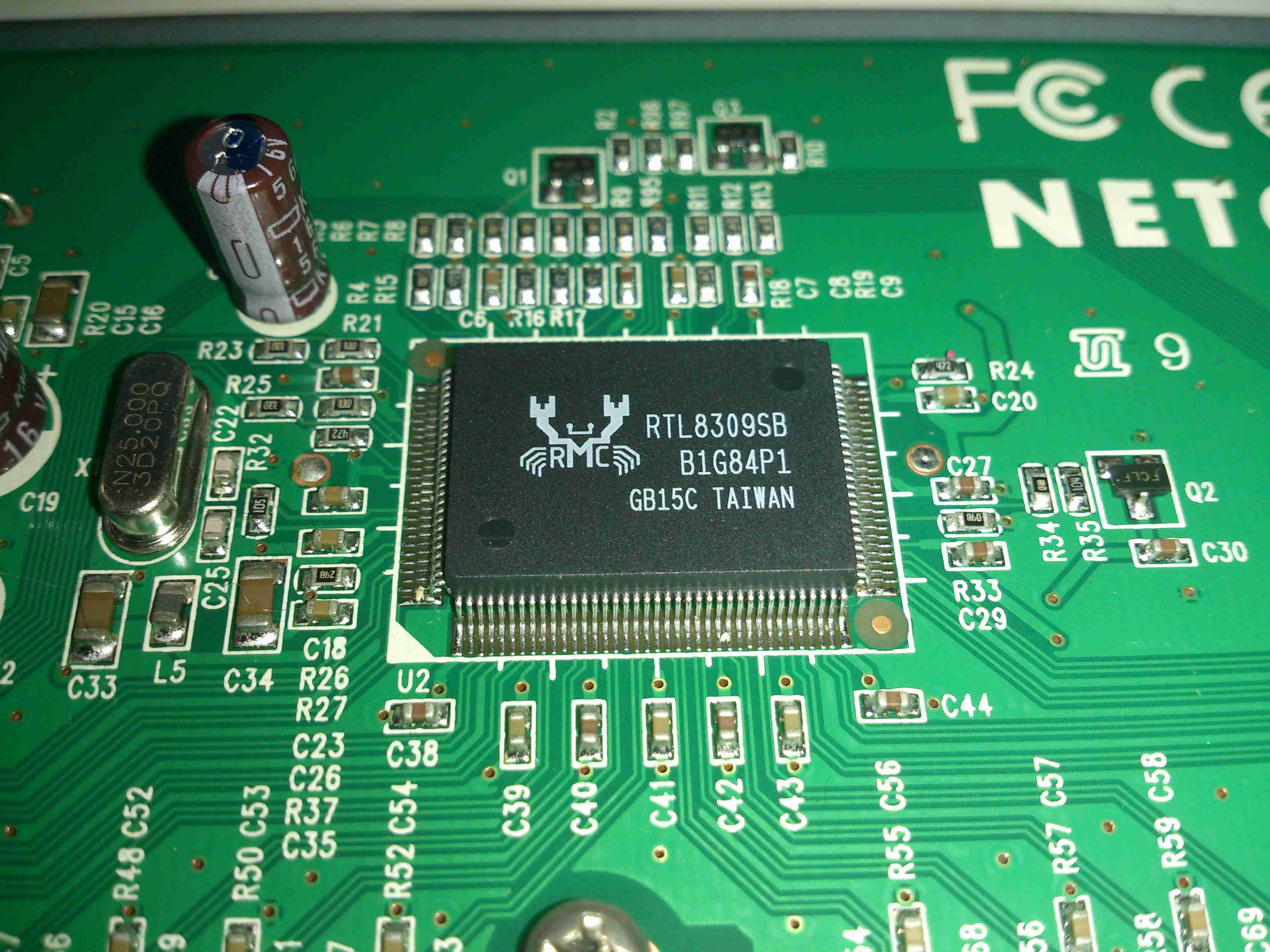
Main Switch IC
All the magic happens in this main IC, a Realtek RTL8309SB Fast Ethernet switch. This is a feature-packed IC, with support for VLAN tagging, but being in a small unmanaged switch the extra features aren’t used.
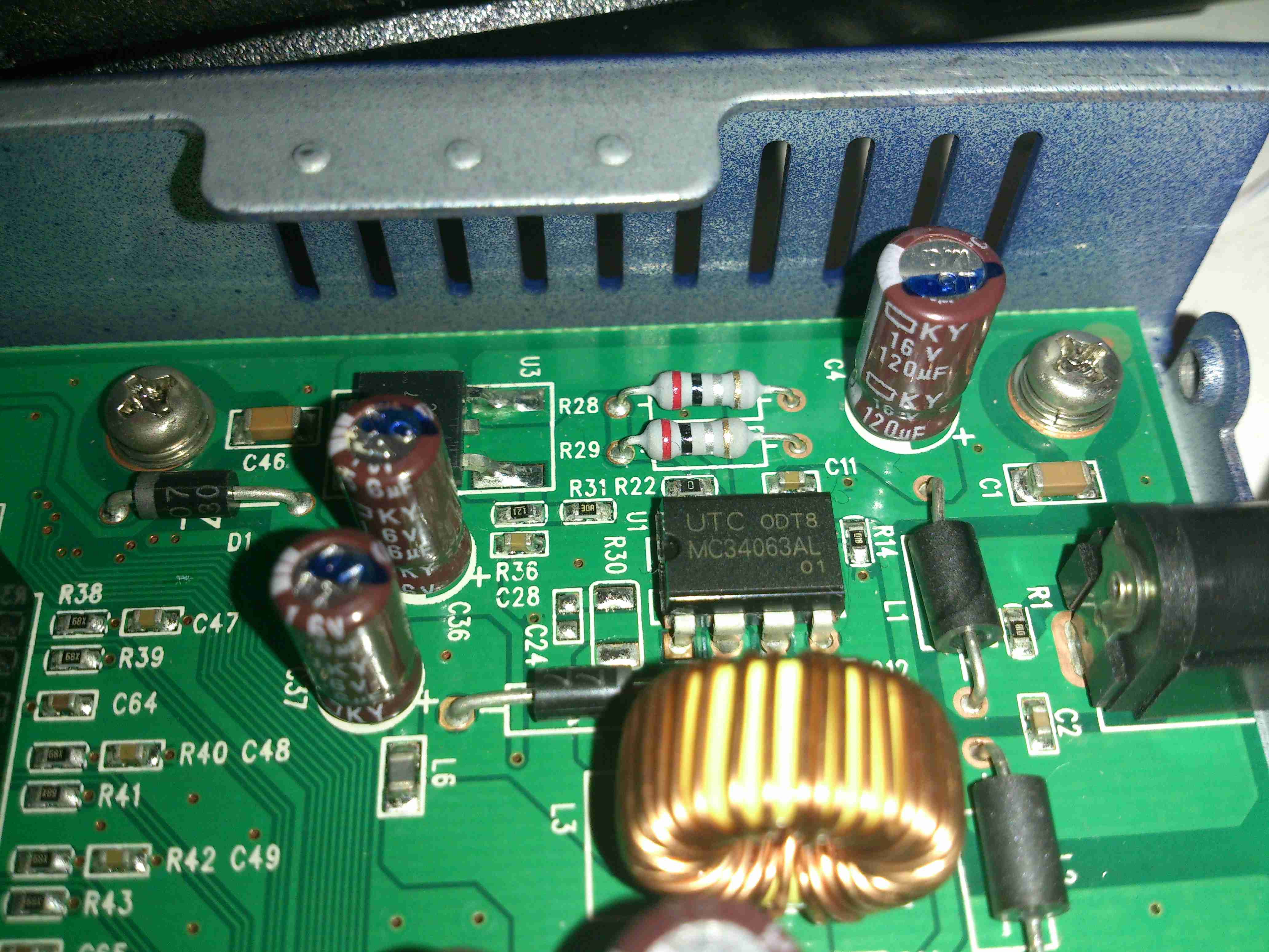
Power Supply
Main power supply is provided by a jelly bean MC34063 DC-DC converter, and an adjustable LM1117 linear regulator. Nothing much special here.
Ethernet Magnetics
The only other parts are the magnetics for the ethernet interfaces, behind the ports themselves.
Tip Jar
If you’ve found my content useful, please consider leaving a donation by clicking the Tip Jar below!
All collected funds go towards new content & the costs of keeping the server online.