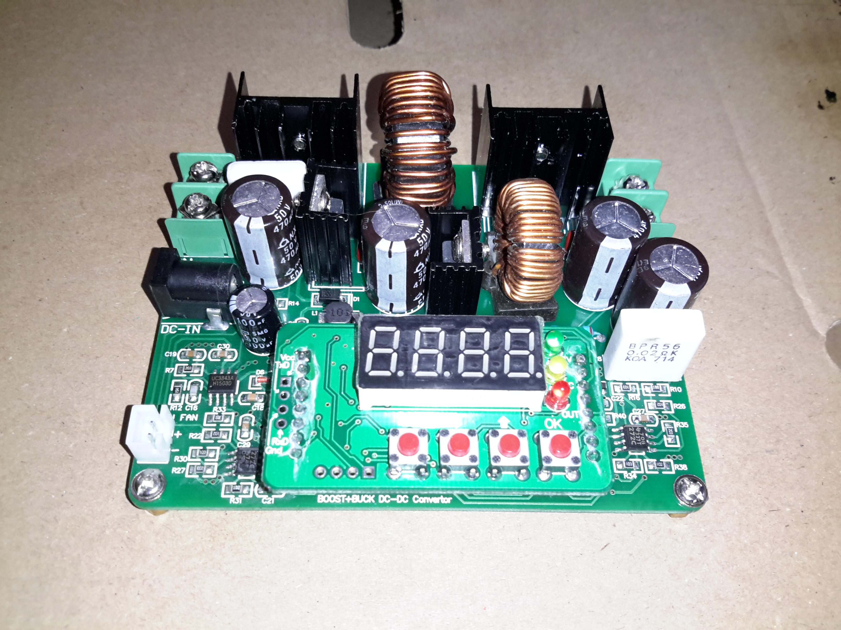
Here’s a useful buck-boost DC-DC converter from eBay, this one will do 36v DC at 6A maximum output current. Voltage & current are selected on the push buttons, when the output is enabled either the output voltage or the output current can be displayed in real time.
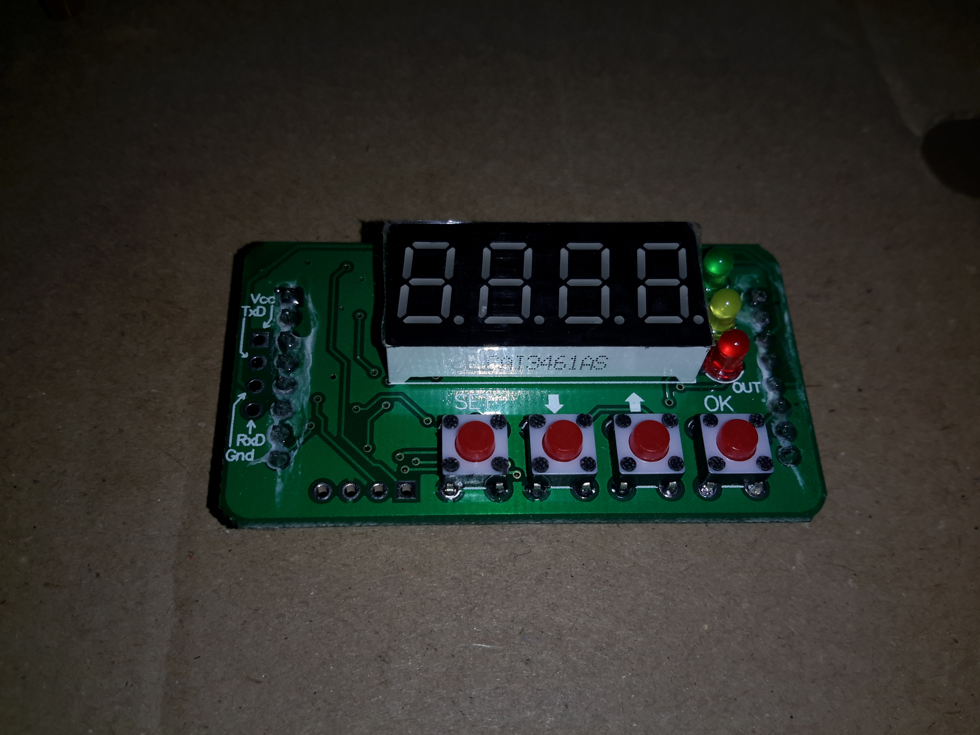
Display PCB
Here’s the display PCB, which also has the STM32 microcontroller that does all the magic. There appears to be a serial link on the left side, I’ve not yet managed to get round to hooking it into a serial adaptor to see if there’s anything useful on it.
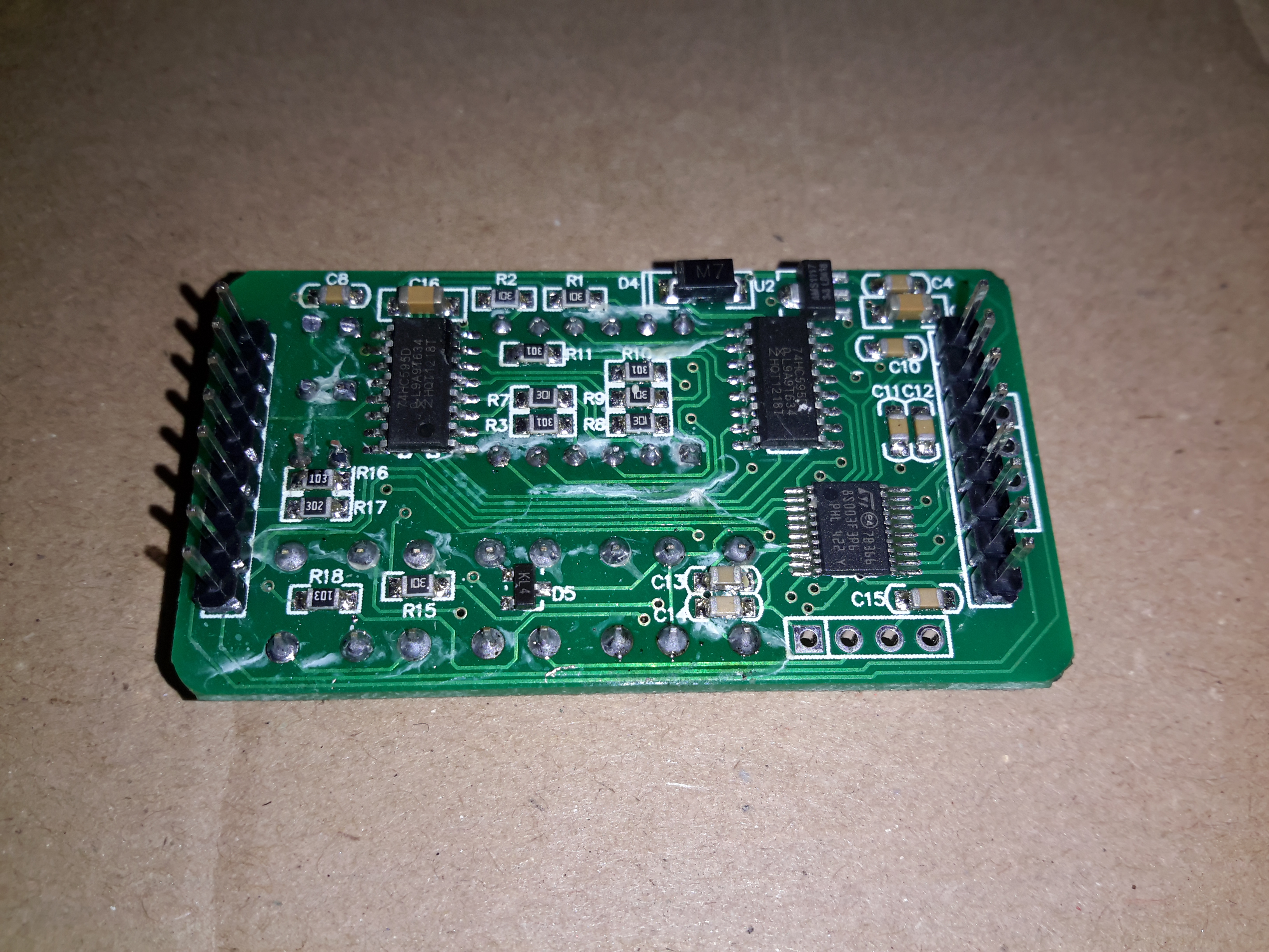
Display Drive & Microcontroller
The bottom of the board holds the micro & the display multiplexing glue logic.
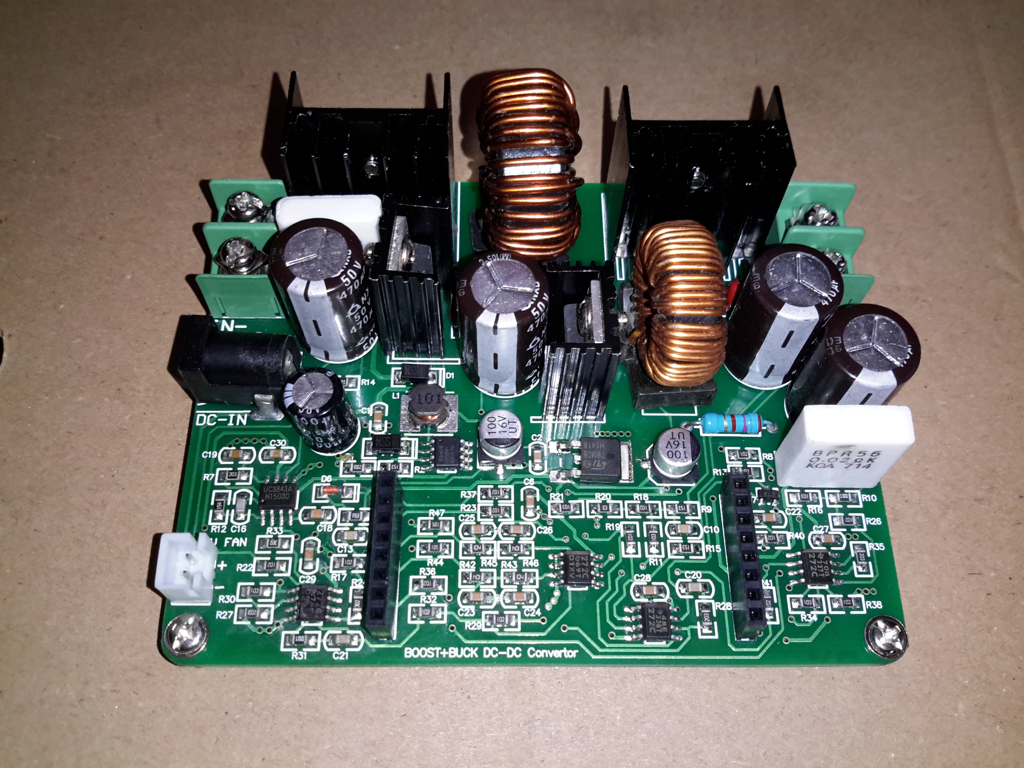
Main PCB
Not much on the mainboard apart from the large switching inductors & power devices. There’s also a SMPS PWM controller, probably being controlled from the micro.
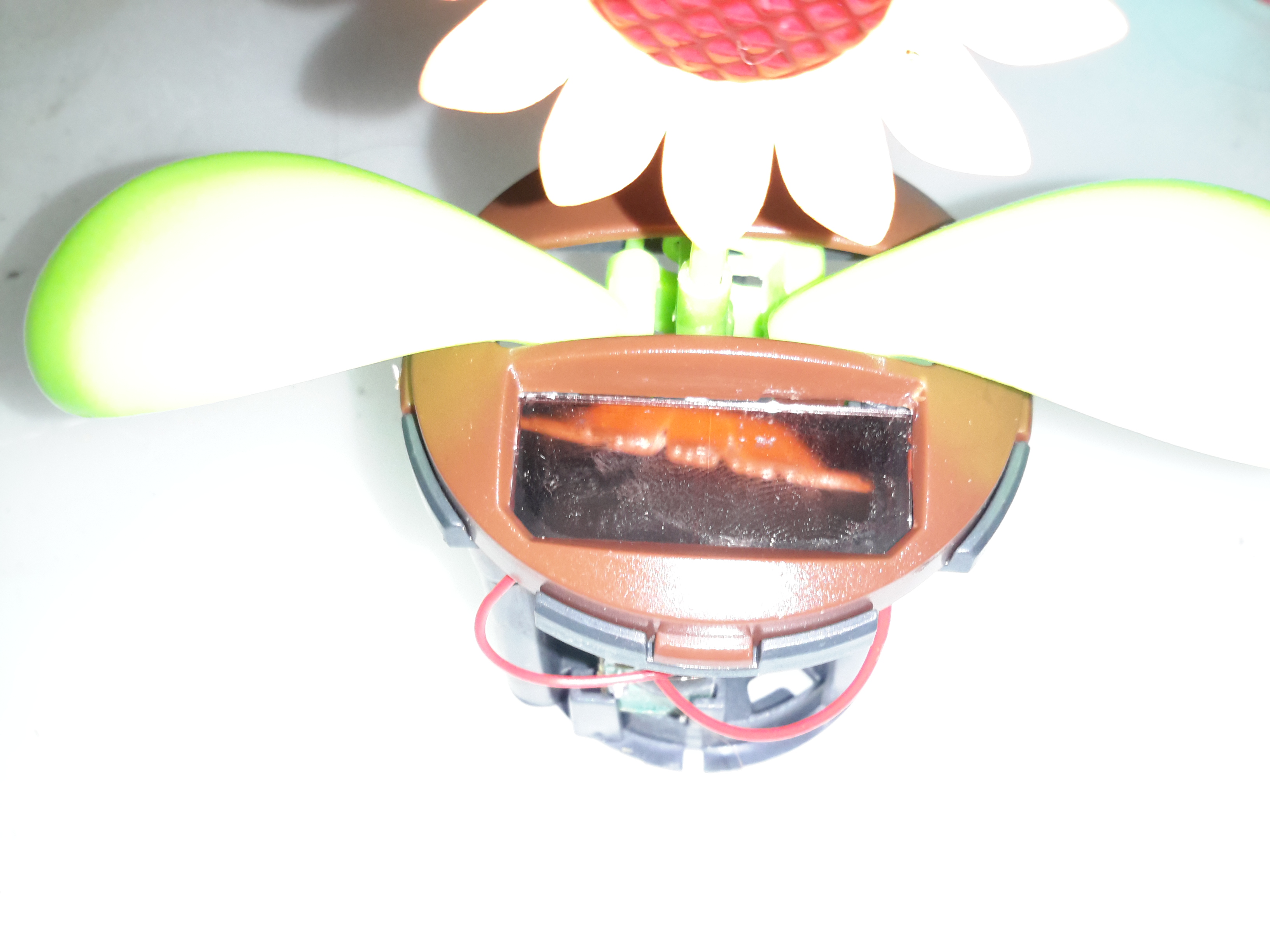
These solar flowers were being sold off at my local Tesco, a pair of them appeared thanks to my child 😉
They have a small solar panel on top, when they’re exposed to bright light, the flower & leaves move as if they’re being blown in a breeze.
Since one of them didn’t work, I figured I’d tear it down.
Solar Cell
The solar cell on the top is similar if not identical to that used on a cheap calculator.
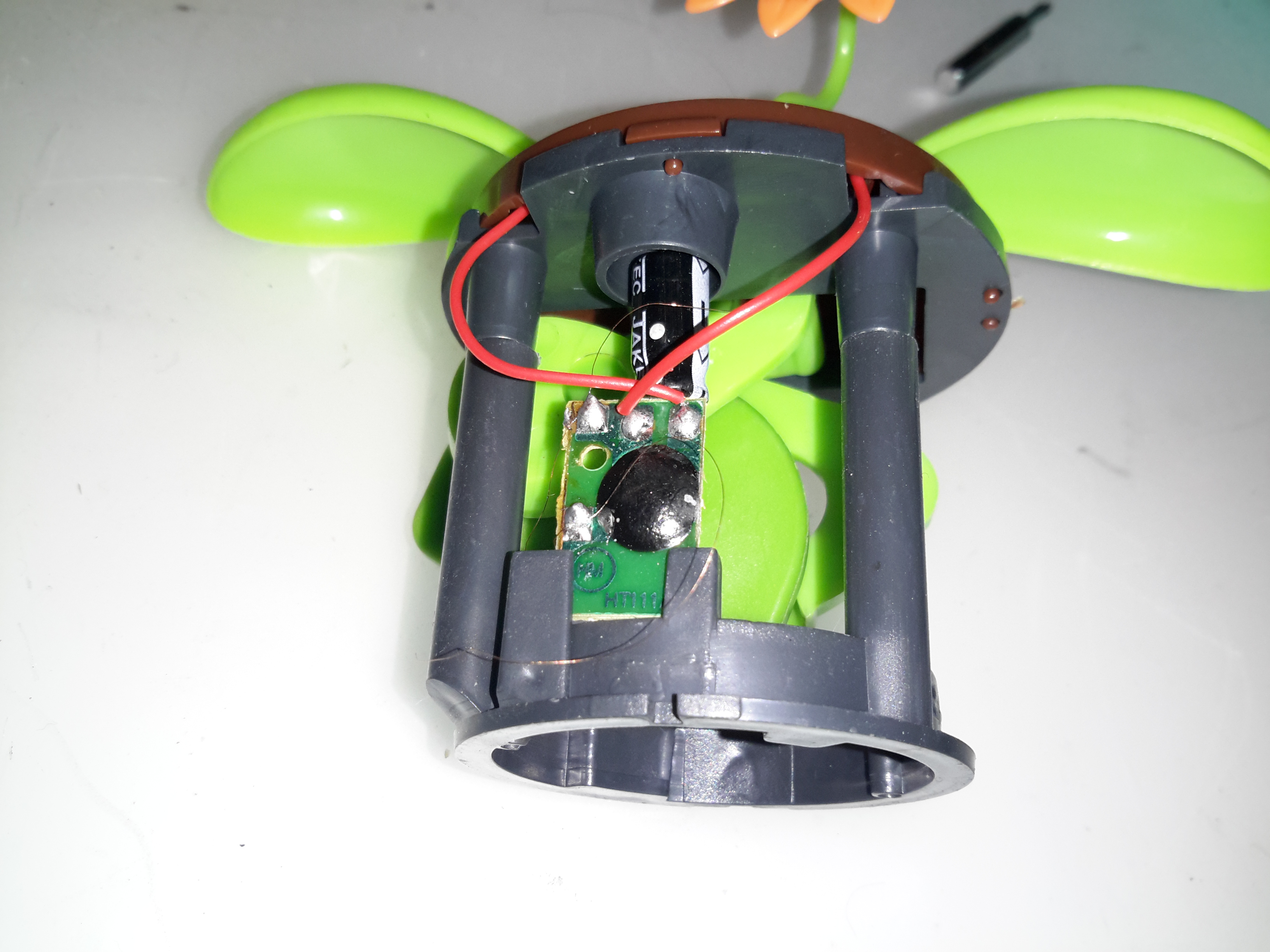
Controller
Not much to the control PCB. Just an electrolytic for smoothing the DC coming from the solar cell & a COB IC.
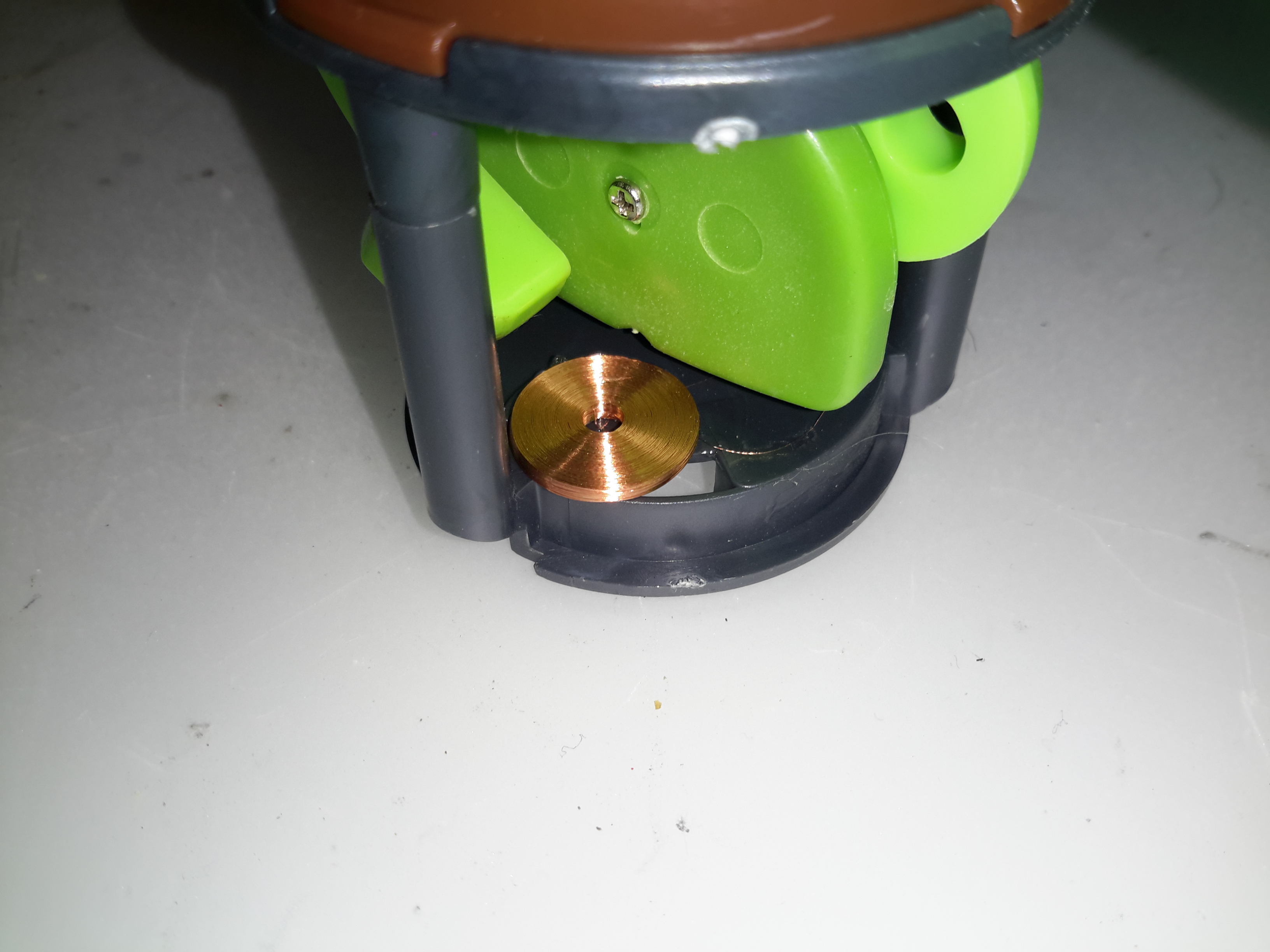
Electromagnet Coil
The IC drives this coil of extremely fine wire, glued to the base of the housing. Attached to the green plastic arm should be a magnet – this one has never worked as the magnet is missing. at 50p a piece, a magnet would cost me more than the whole device. So it’s the bin for this one.
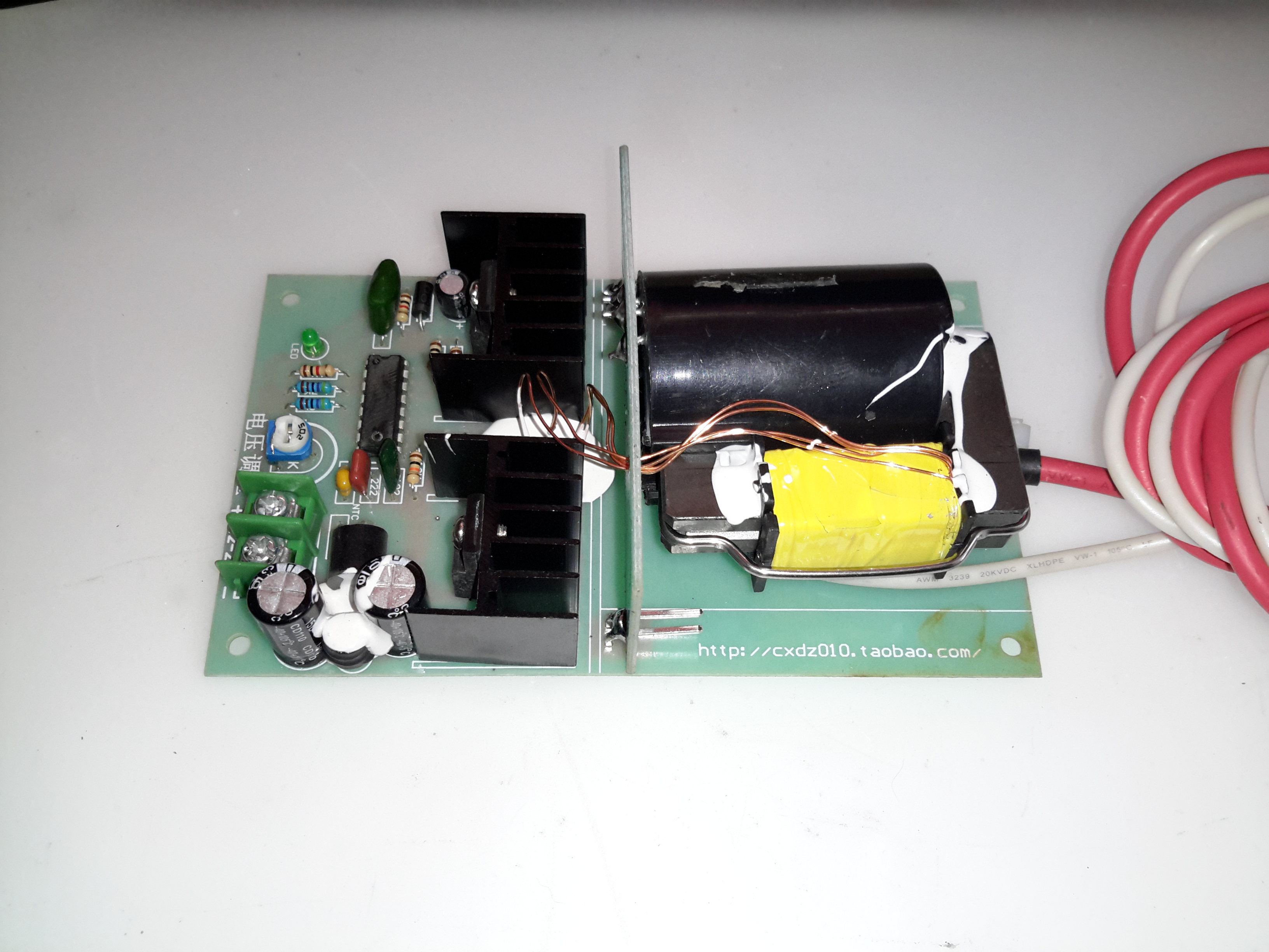
I have found myself needing some more in the way of High Voltage supplies of late, with the acquisition of the new He-Ne laser tubes, so I went trawling eBay for something that would be suitable to run these tubes. (I currently only have a single He-Ne laser PSU brick, and they’re notoriously hard to find & rather expensive).
This supply is rated at 1kV-10kV output, at 35W power level. Unfortunately this supply isn’t capable of sustaining the discharge in a large He-Ne tube, the impedance of the supply is far too high. Still, it’s useful for other experiments.
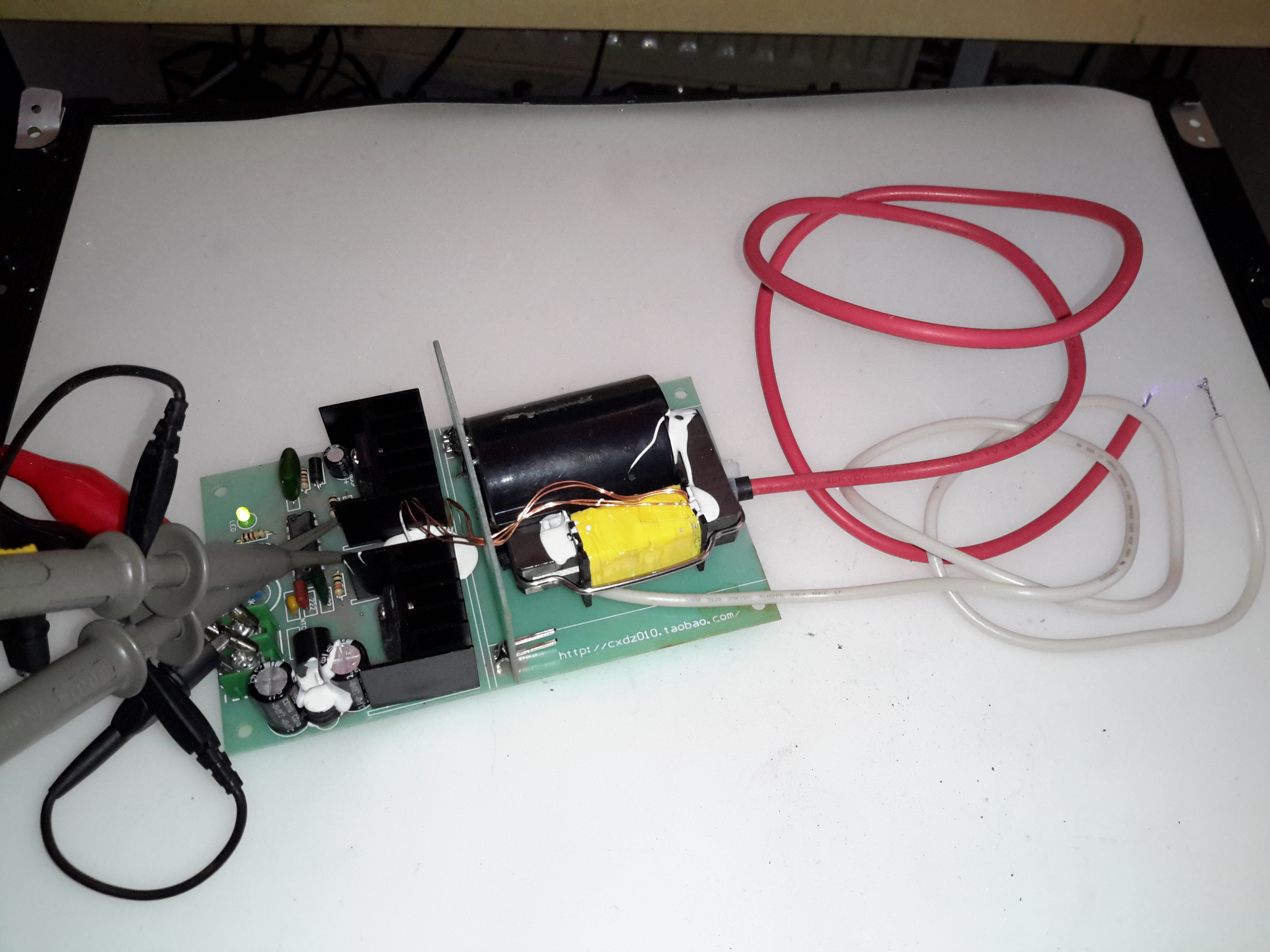
The flyback-type transformer clearly isn’t a surplus device from CRT manufacture, as there are very few pins on the bottom, and none of them connect to the primary side. The primary is separately wound on the open leg of the ferrite core.
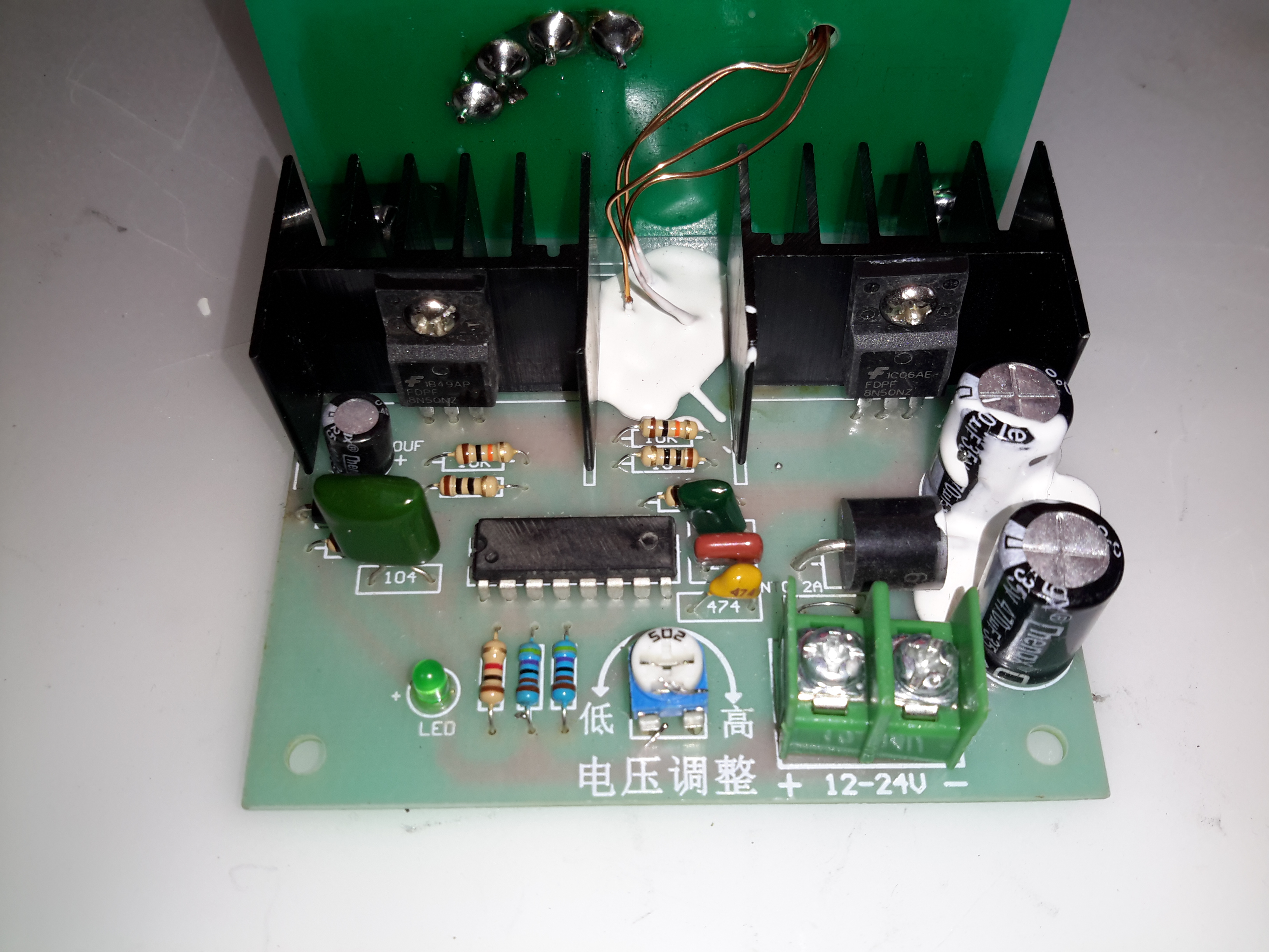
Drive Electronics
The drive electronics are pretty simple, there’s a controller IC (with the number scrubbed off – guessing it’s either a 556 dual timer or a SMPS controller), a pair of FDP8N50NZ MOSFETs driving the centre-tapped primary winding.
The drive MOSFETs aren’t anything special in this case: they’re rated at 500v 8A, 850mΩ on resistance. This high resistance does make them get rather hot even with no load on the output, so for high power use forced-air cooling from a fan would definitely be required.
Test Setup
Here’s the supply on test, I’ve got the scope probes connected to the gate resistors of the drive MOSFETs.
Waveforms
On the scope the primary switching waveforms can be seen. The FETs operate in push-pull mode, there’s a bit of a ring on the waveform, but they’re pretty nice square waves otherwise.
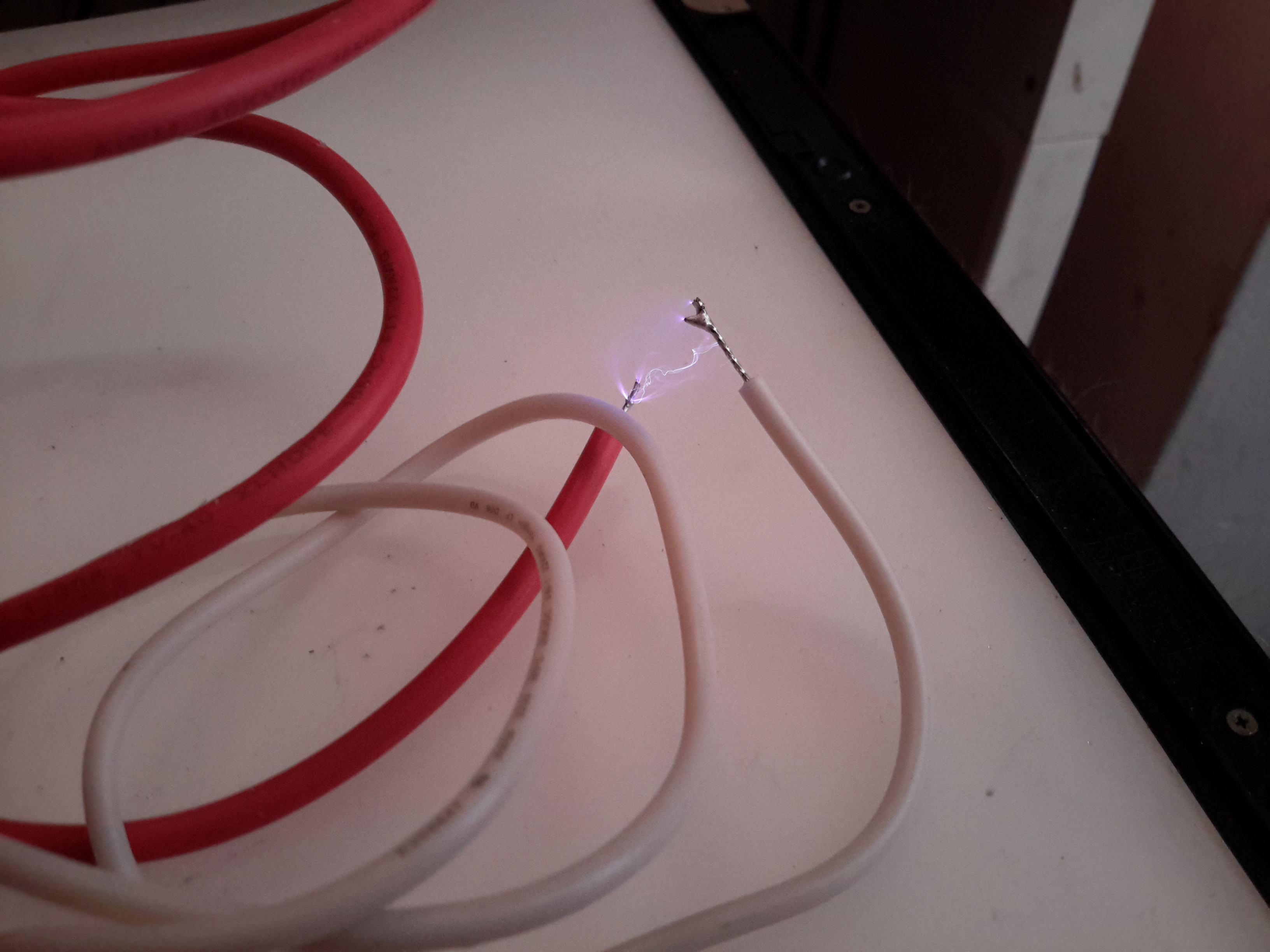
Arc
At maximum power on 12v input, about 25mm of gap is possible with an arc.
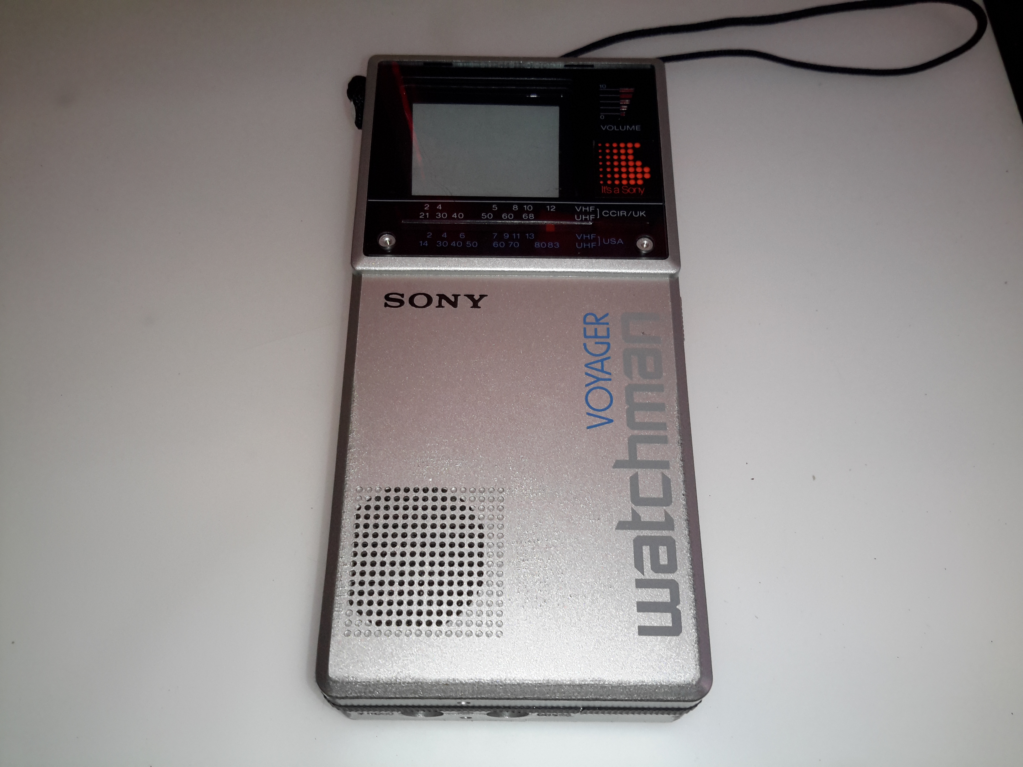
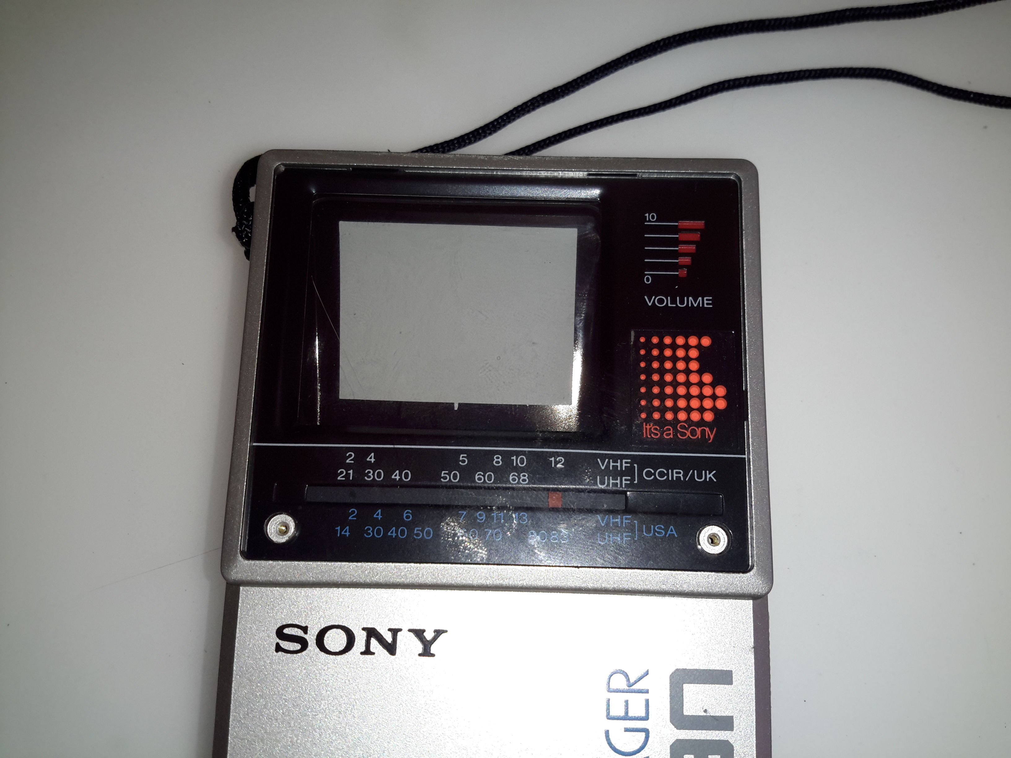
Here’s an oddity from the 1980’s – a CRT-based portable TV, with a very strangely shaped tube. Sony produced many types of flat CRTs back in the 80’s, with the electron gun at 90° to the curved phosphor screen.
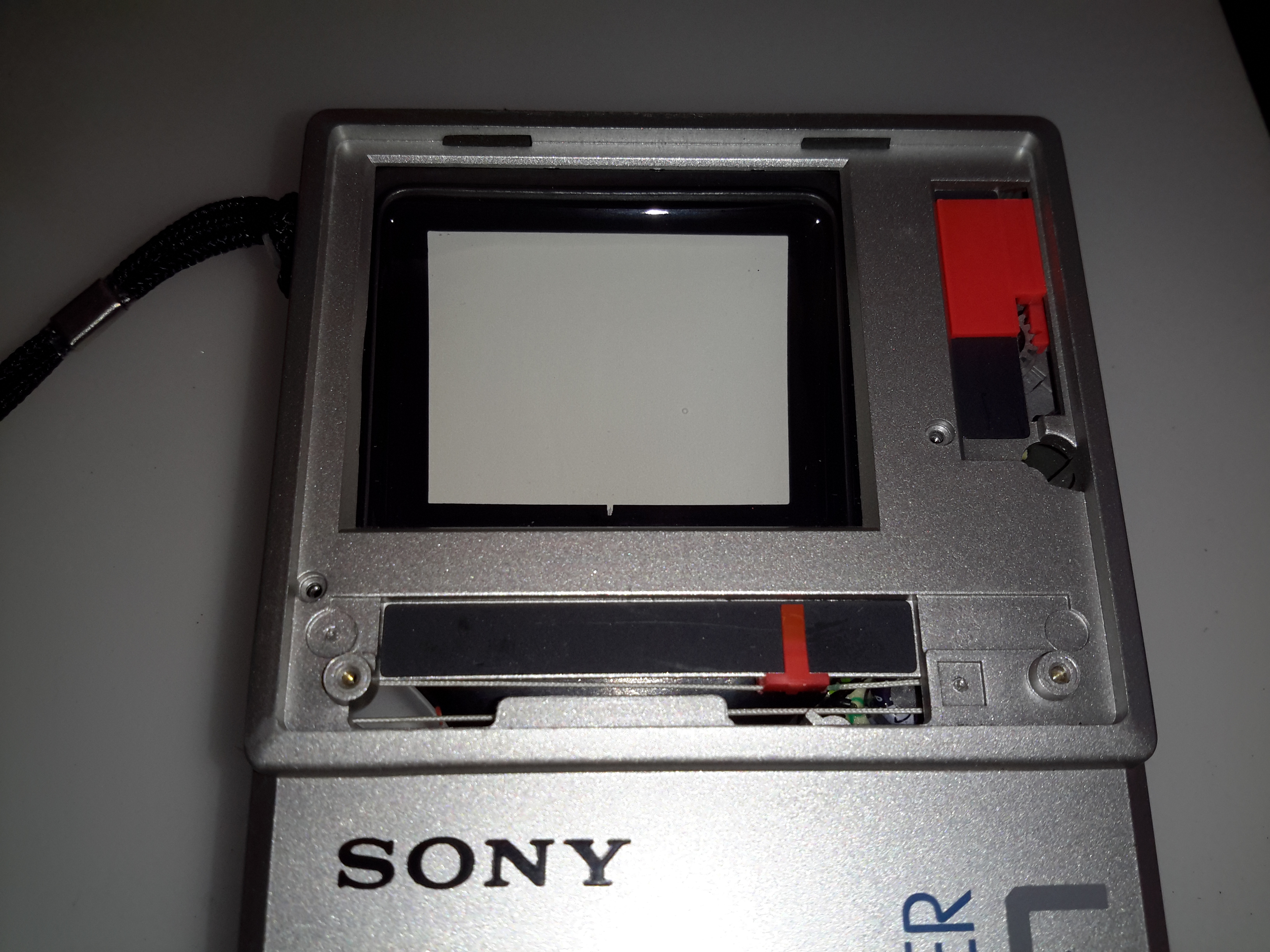
Front Panel
The front panel has the display window, along with the tuning & volume indicators. Unfortunately since analogue TV transmissions have long been switched off, this unit no longer picks up any transmissions off the air, but it can be modified to accept a composite video input.
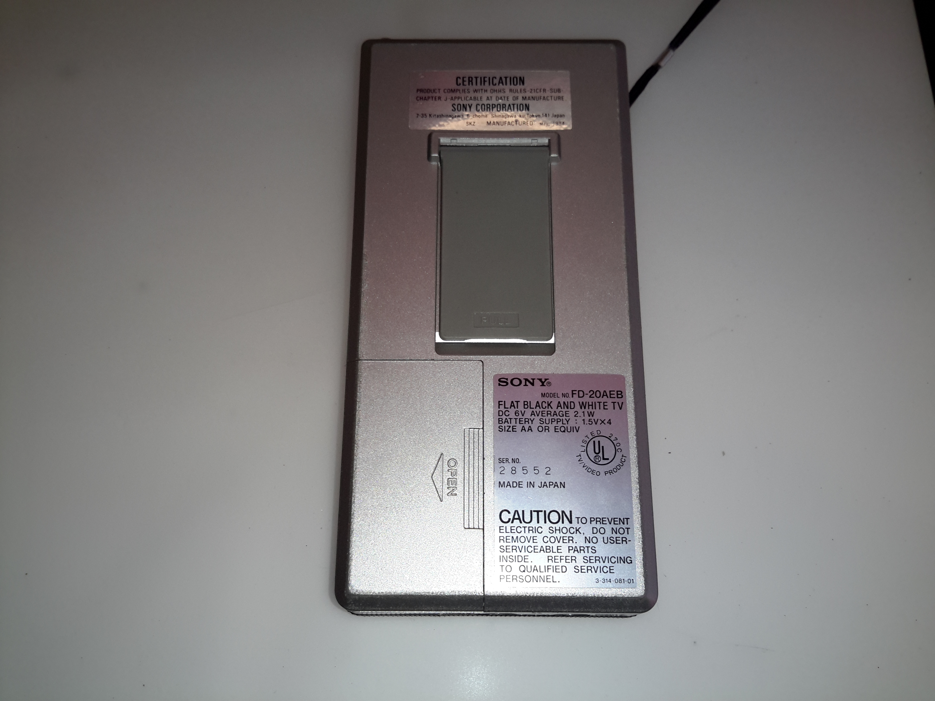
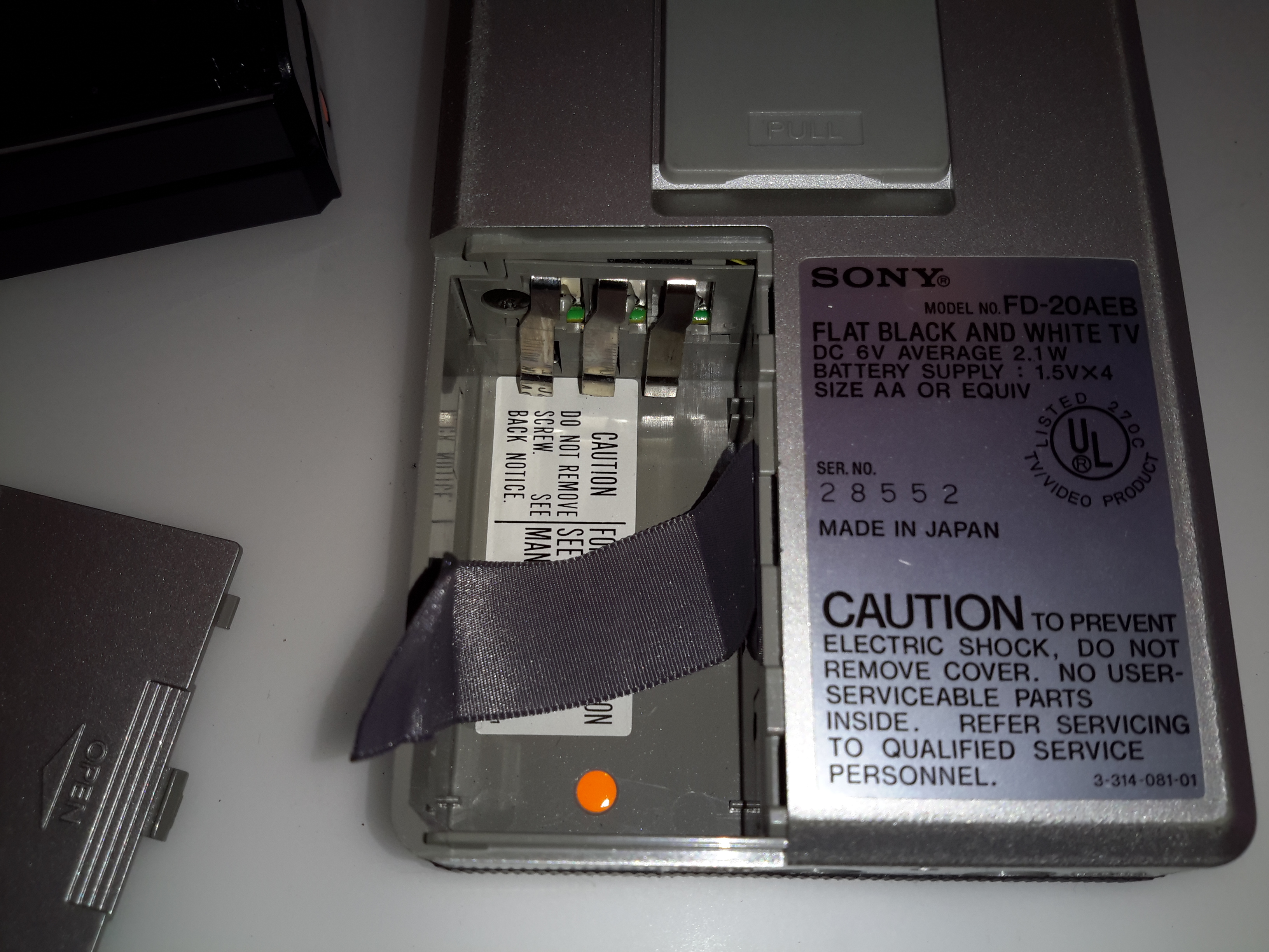
Back Panel
The back panel has the battery compartment & the tilt stand.
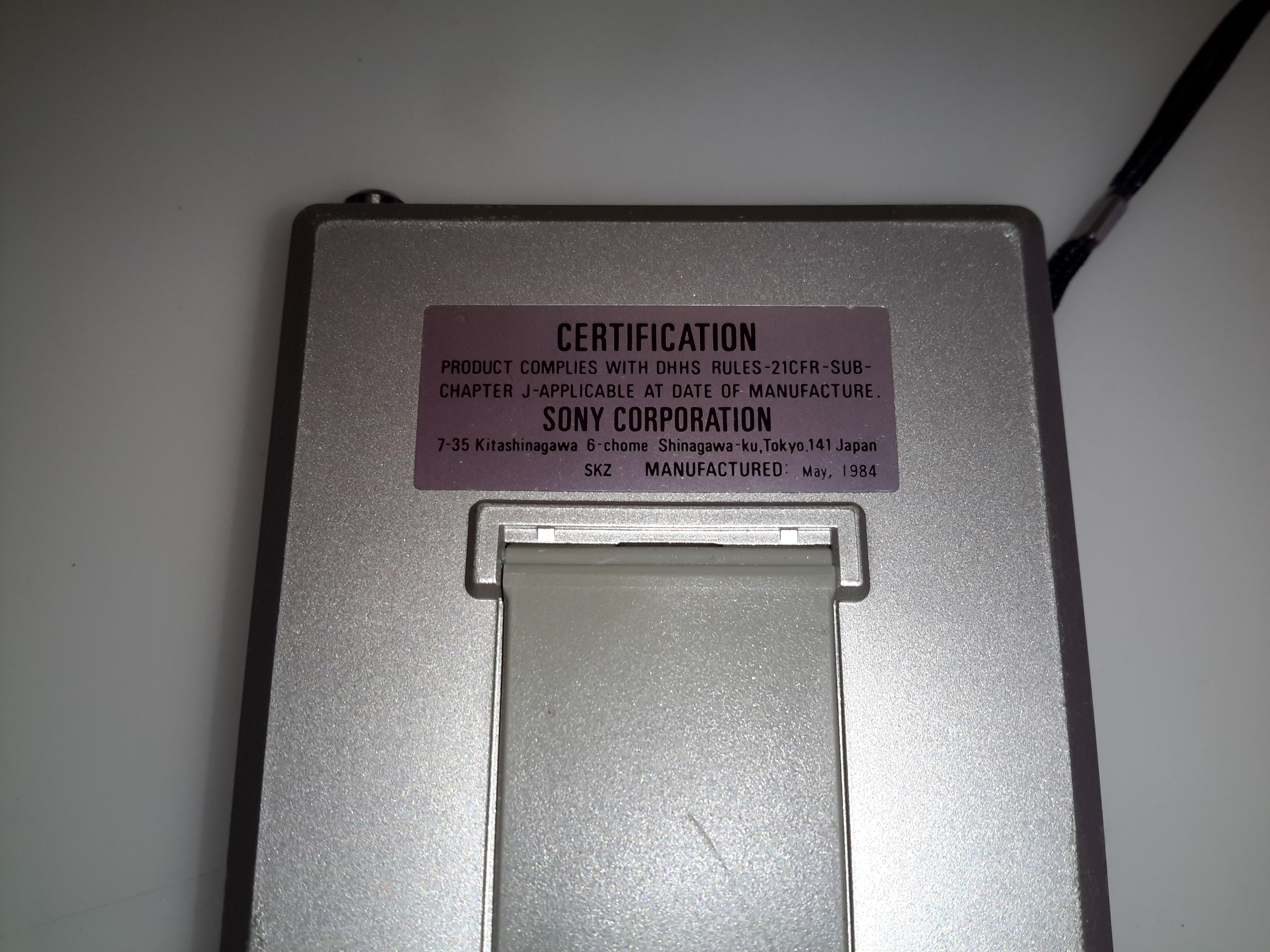
Certification
The certification label reveals this unit was manufactured in May 1984, 32 years ago!
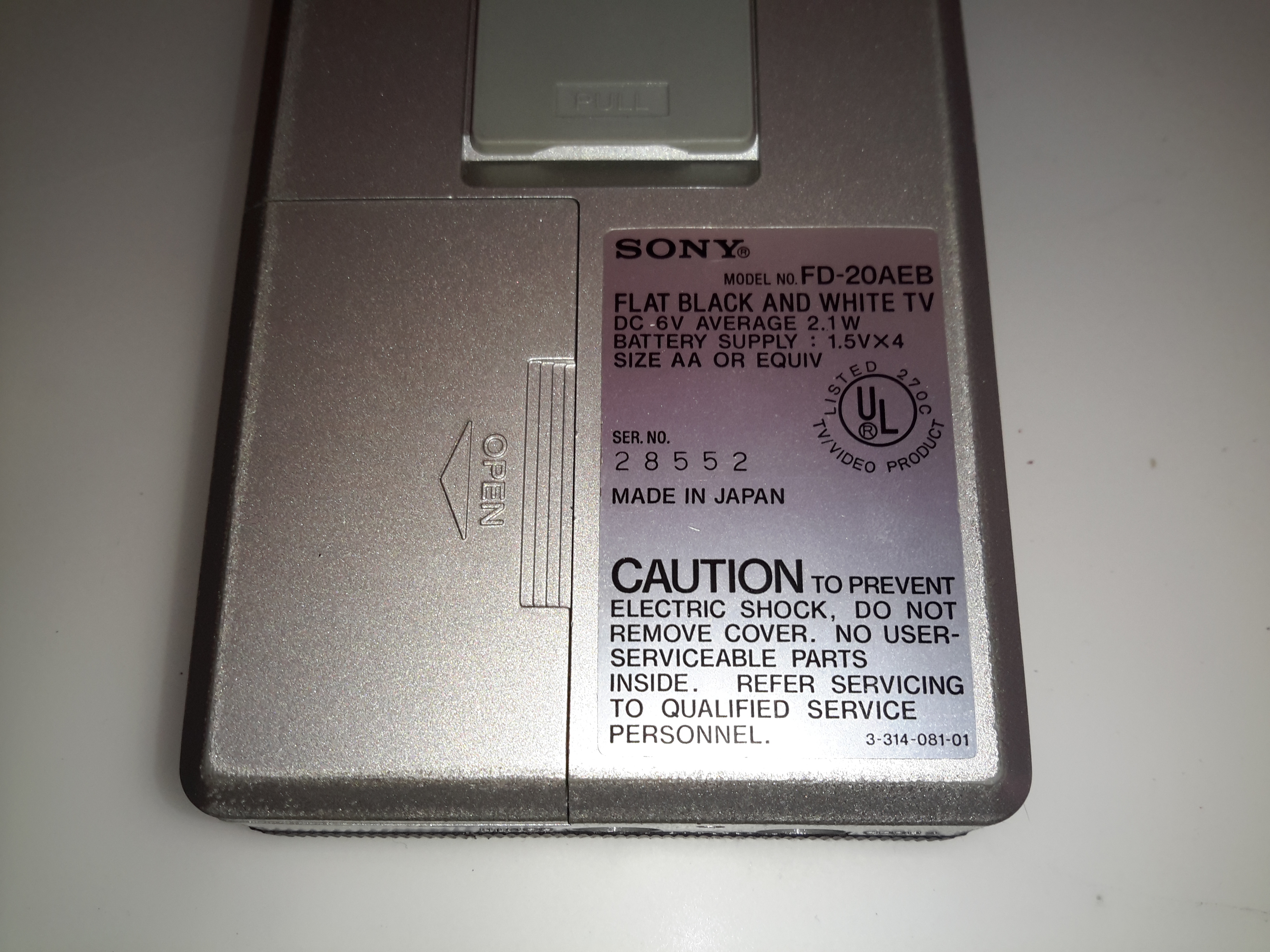
Spec. Label
Rated at 6v, ~2.1W this device uses surprisingly little power for something CRT based.
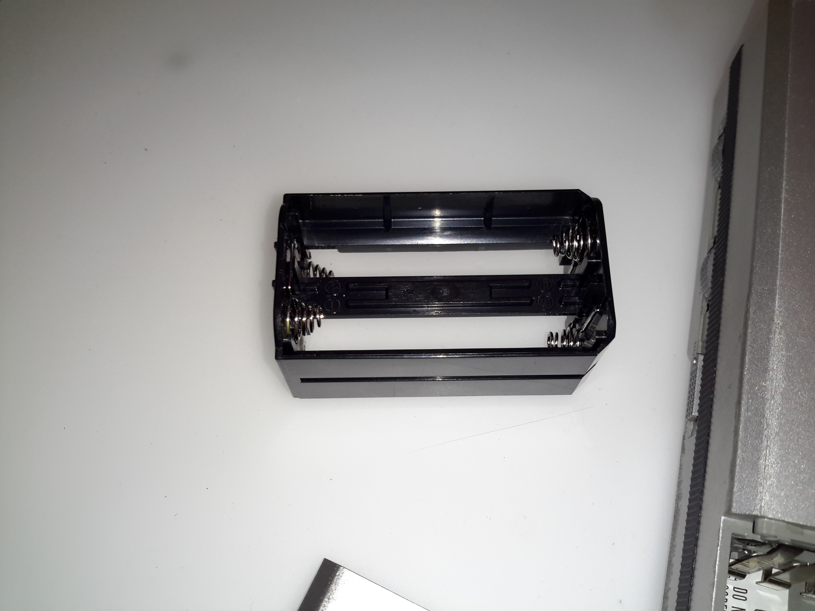
Battery Holder
The battery holder is a little unique, this plastic frame holds 4 AA cells, for a 6v pack.
Battery Compartment
The battery holder slots into the back of the TV, there’s also an extra contact that the service manual mentions is for charging, so I assume a rechargeable 6v battery pack was also available.
Front Panel Removed
Removing a pair of pin-spanner type screws allows the front glass & screen printed CRT surround to be removed. Not much more under here other than the pair of screws that retain the CRT in the front frame.
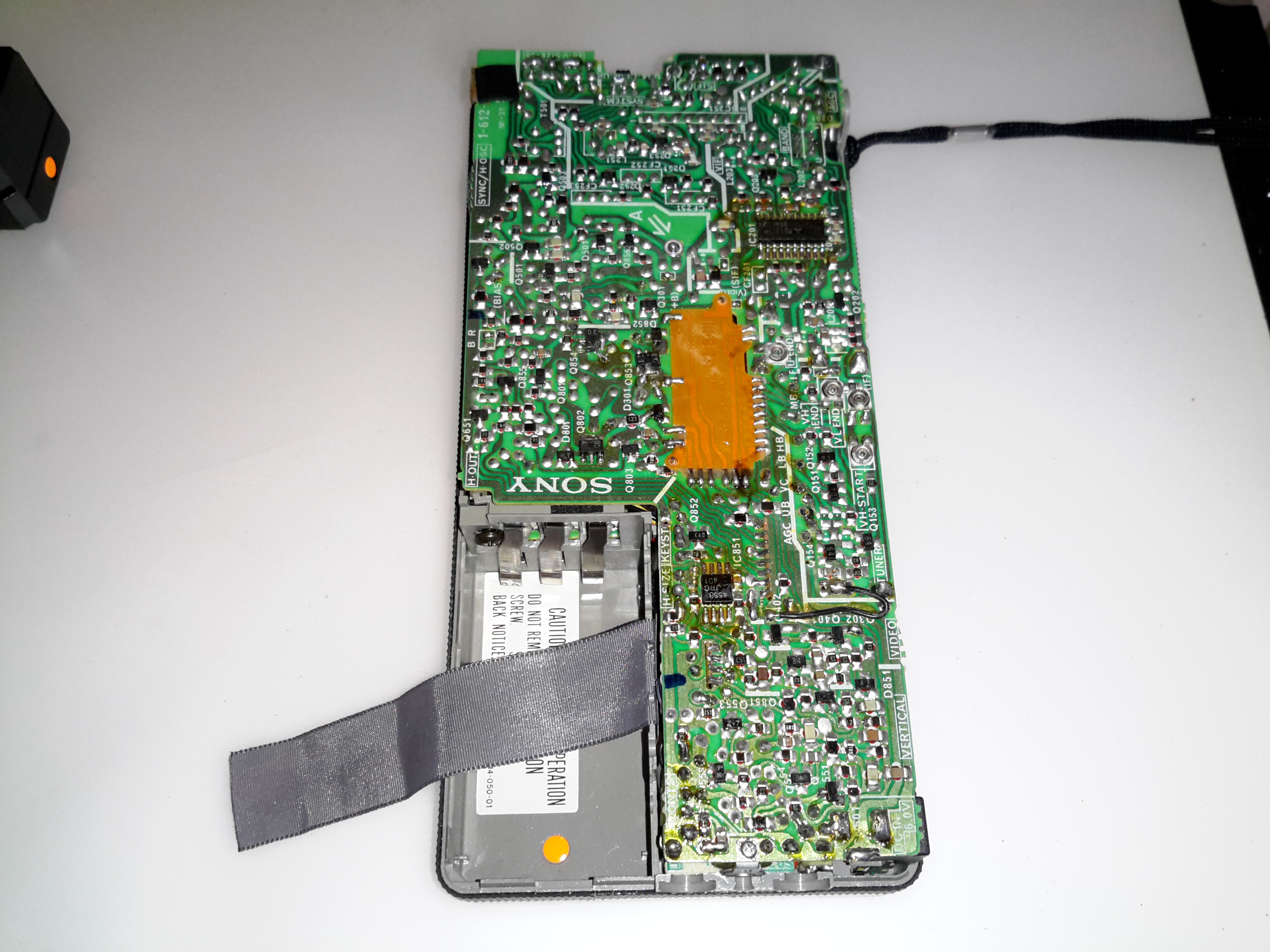
Back Cover Removed
Here’s the back cover removed, after unscrewing some very small screws. As per usual with Sony gear, the electronics is extremely compacted, using many flat flex cables between the various PCBs. The main PCB is visible at the back, this has all the deflection circuitry, RF tuner, Video IF, Audio IF, video amplifier & composite circuitry.
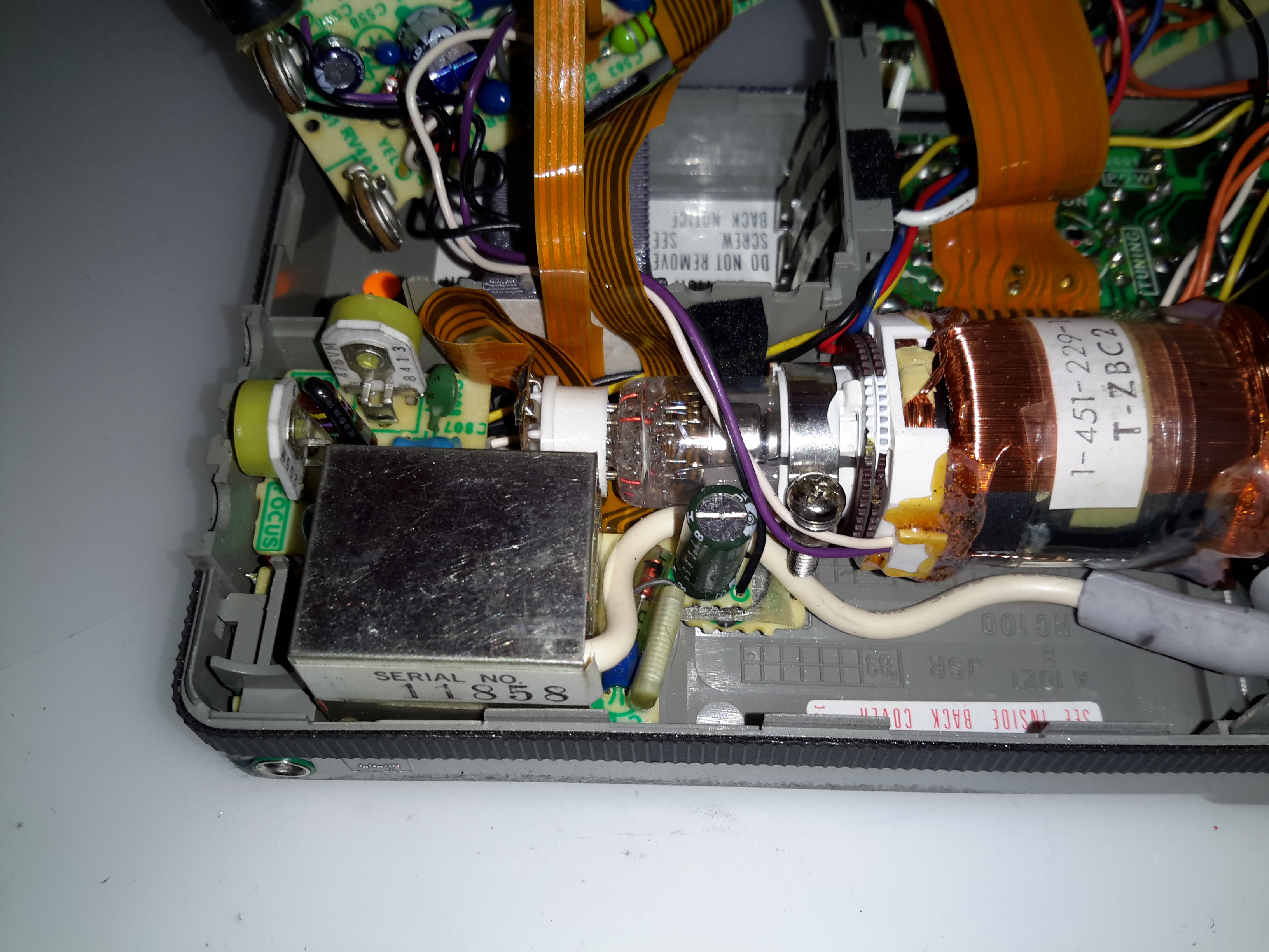
CRT Electron Gun & Flyback Transformer
Lifting up the main board reveals more PCBs – the high voltage section for the CRT with the flyback transformer, focus & brightness controls is on the left. The loudspeaker PCB is below this. The CRT electron gun is tucked in behind the flyback transformer, it’s socket being connected to the rest of the circuitry with a flat flex cable.
CRT Rear
Here’s the back of the CRT, the phosphor screen is on the other side of the curved glass back. These tubes must require some additional deflection complexity, as the geometry will change as the beam scans across the screen. There’s a dynamic focus circuit on the schematics, along with extensive keystone adjustments.
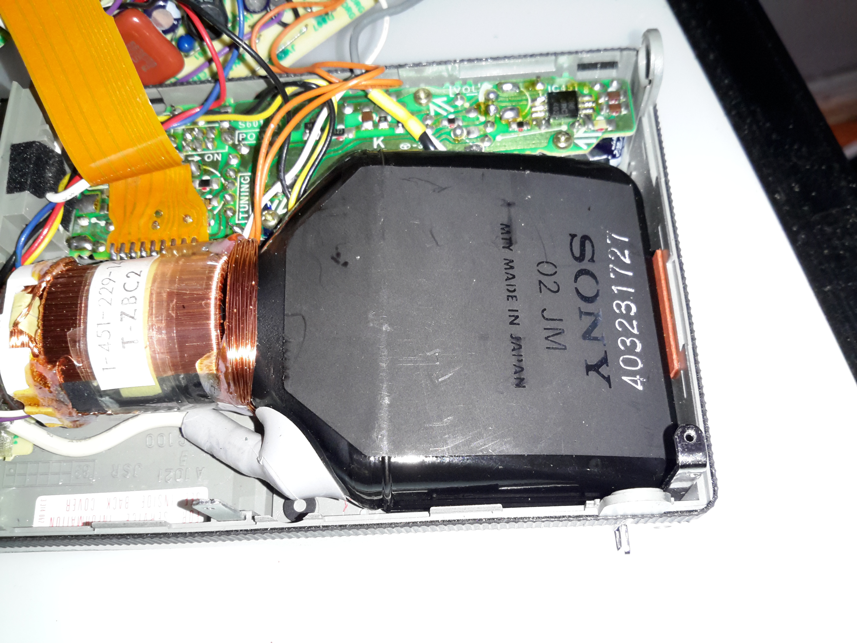
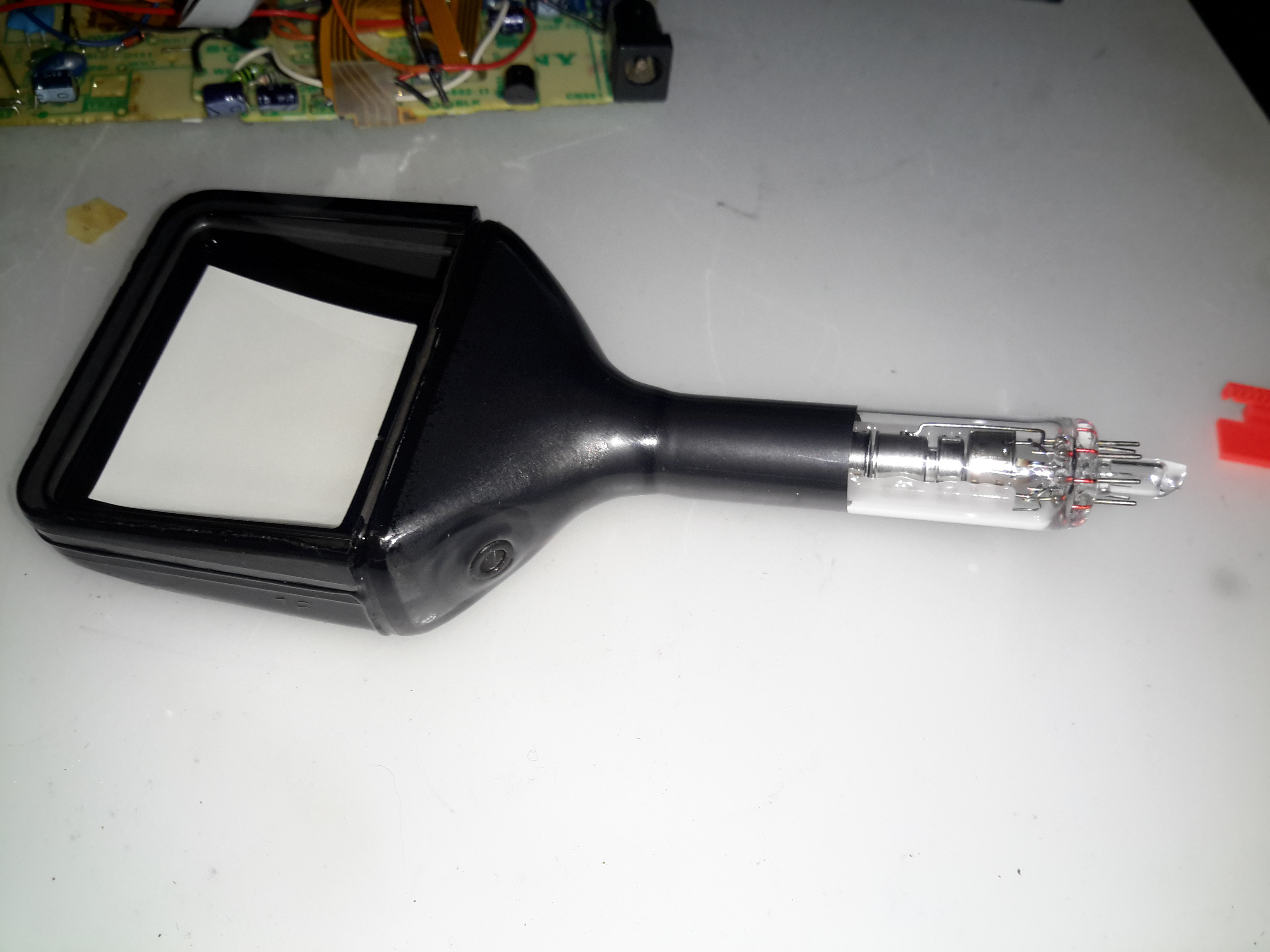
Sony 02-JM Flat CRT
Here’s the tube entirely extracted from the chassis. The EHT connection to the final anode is on the side of the tube bell, the curved phosphor screen is clearly visible. The one thing I can’t find in this CRT is a getter spot, so Sony may have a way of getting a pure enough vacuum that one isn’t required.
I’d expect the vertical deflection waveforms to be vastly different on this kind of CRT, due to the strange screen setup. Not much of a beam movement is required to move the spot from the top to the bottom of the screen.
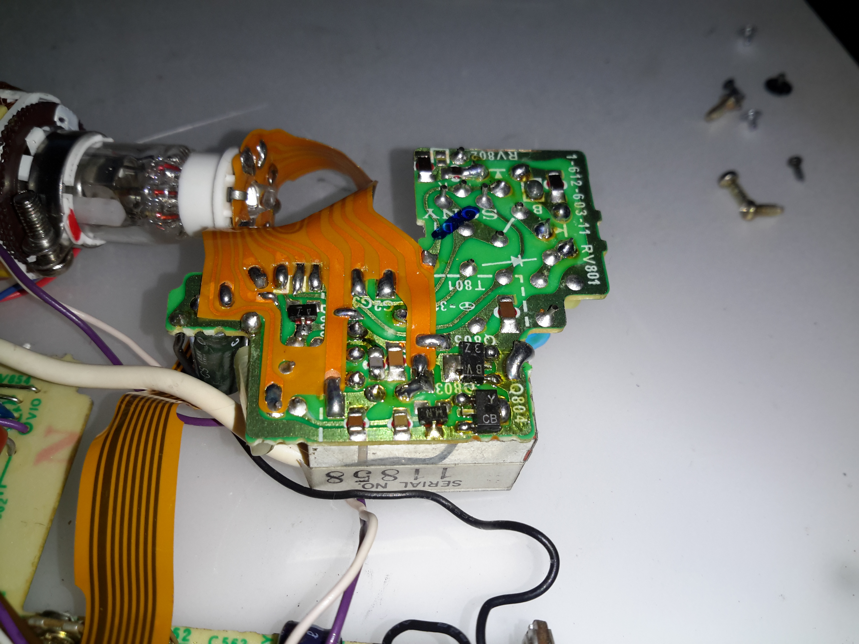
HV Module
No doubt to keep the isolation gaps large, all the high voltages are kept on a separate small PCB with the flyback transformer. This board generates the voltages for the electron gun filament, focus grid & the bias to set the beam current (brightness) as well.
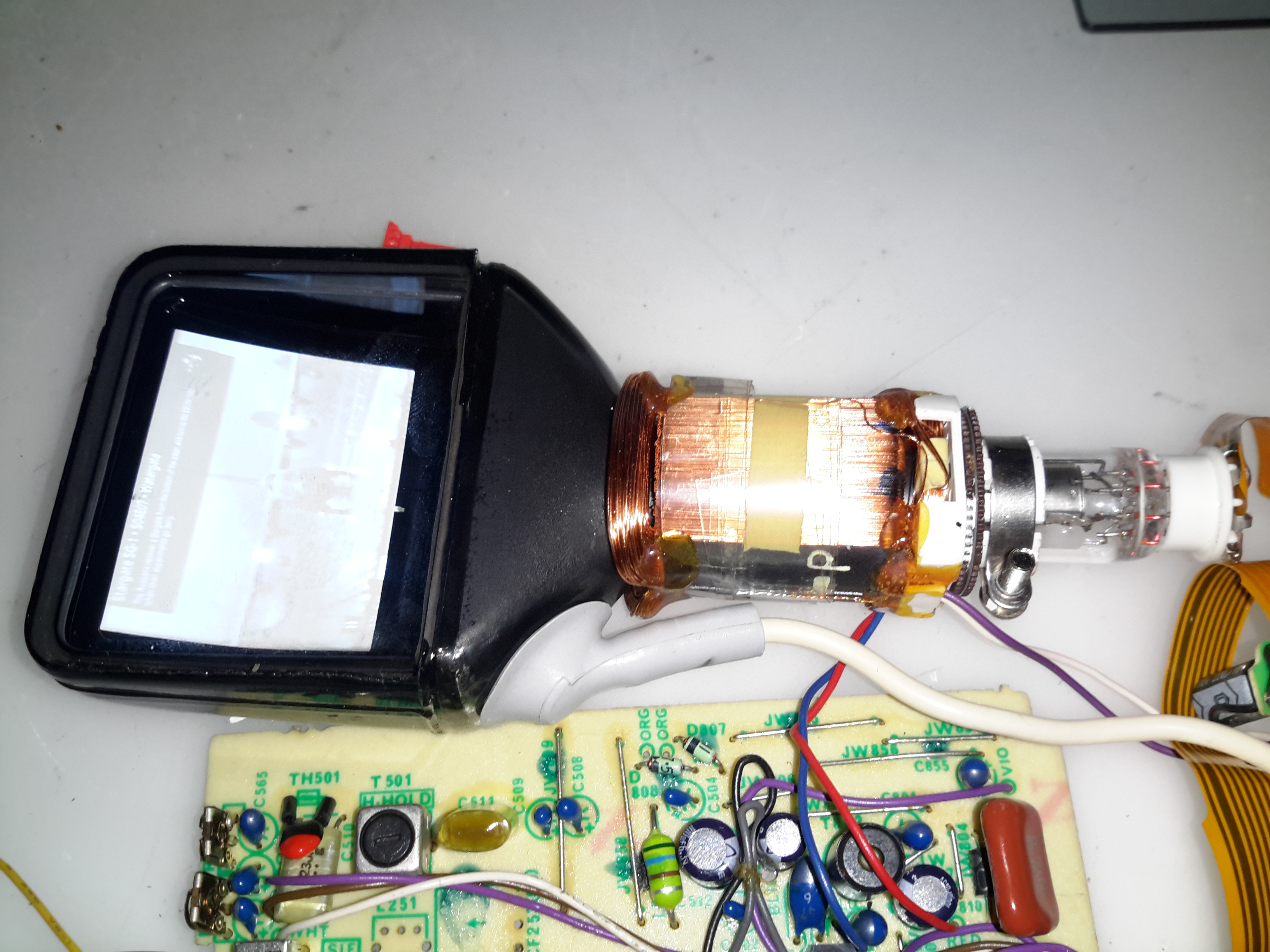
Bare CRT
Here the deflection yoke has been removed from the CRT, showing the very odd shape better. These tubes are constructed of 3 pieces of glass, the bell with electron gun, back glass with phosphor screen & front viewing window glass. All these components are joined with glass frit.
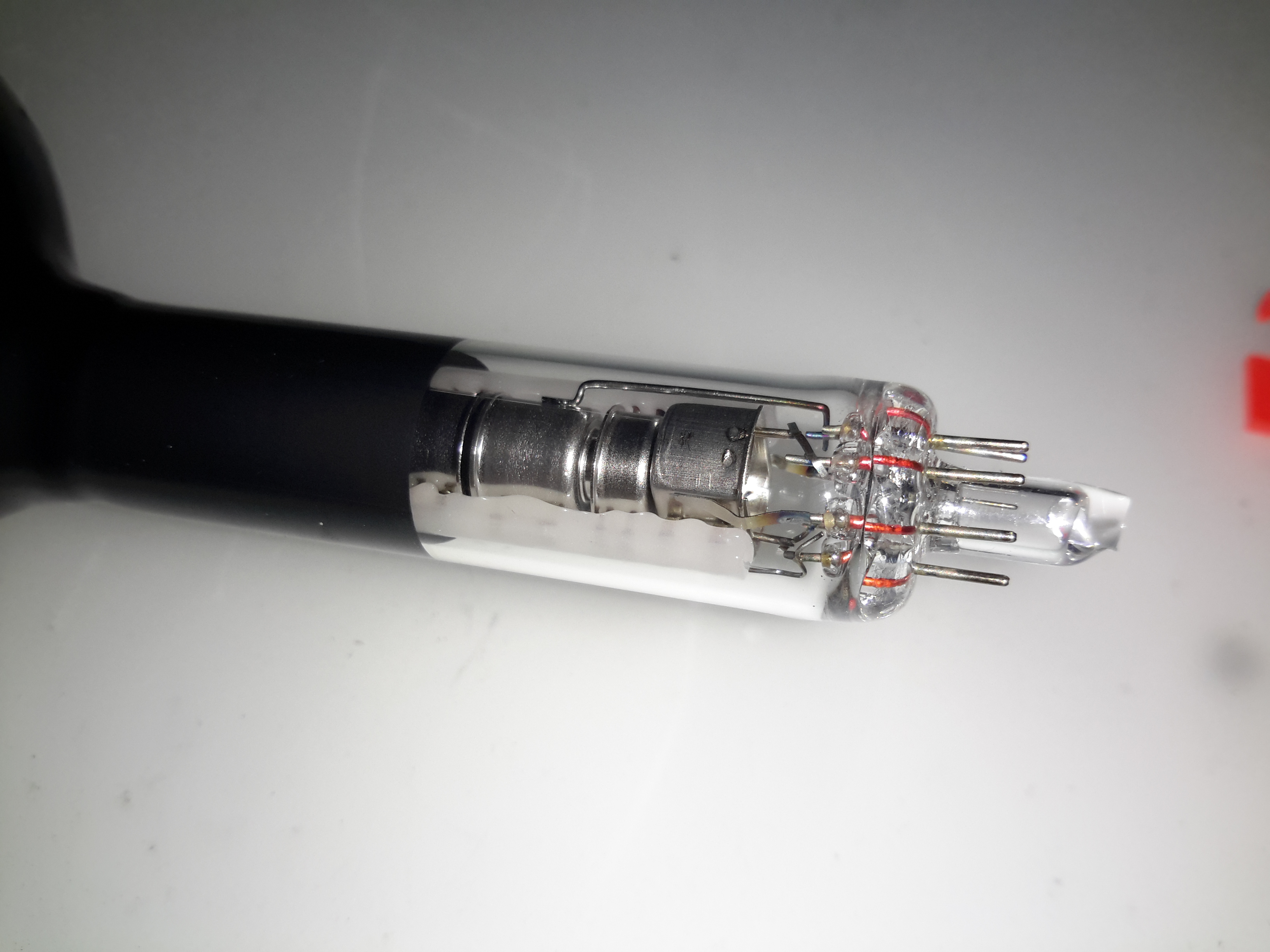
Electron Gun
The electron gun in the neck looks to be pretty much standard, with all the usual electrodes.
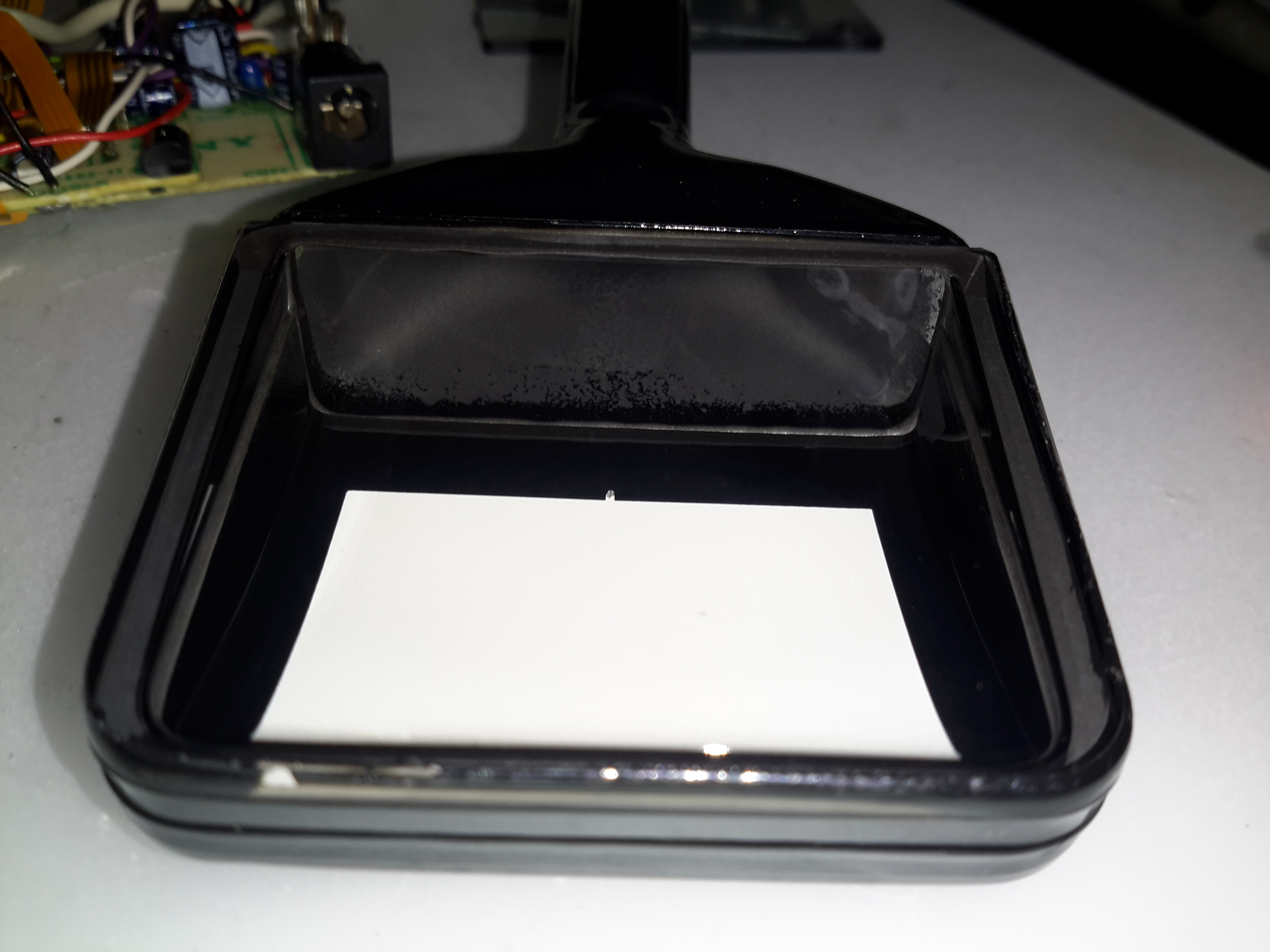
Viewing Window
Here’s a view from the very top of the CRT, the curve in the screen is very obvious here. The electron beam emerges from the bell at the back.
FD-20 Schematic
Here’s the full schematic of the entire TV, I extracted this from a service manual I managed to find online.
More to come on hacking this unit to accept a standard composite video input, from something such as a Raspberry Pi!
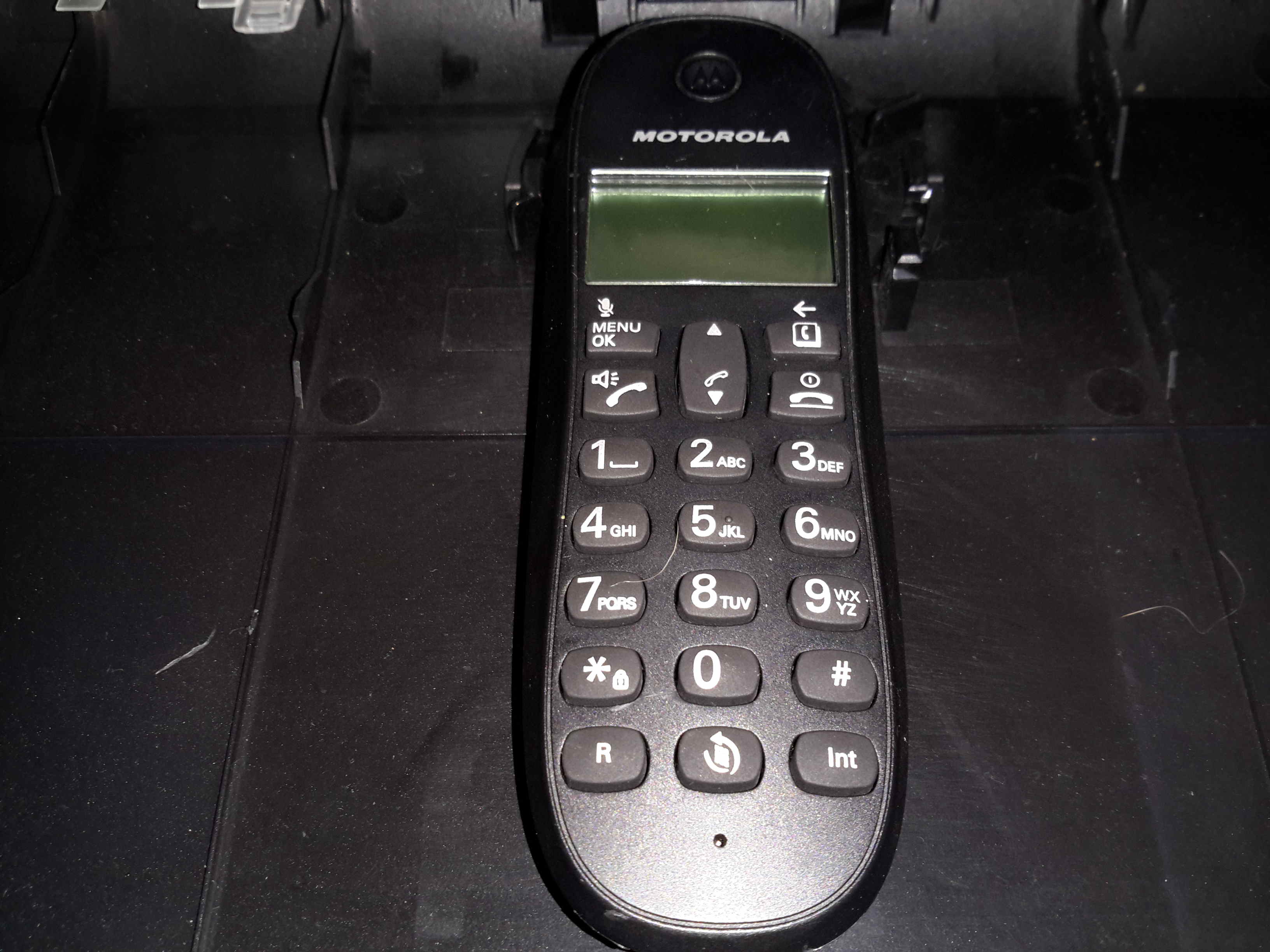
Another random teardown from the junk box time!
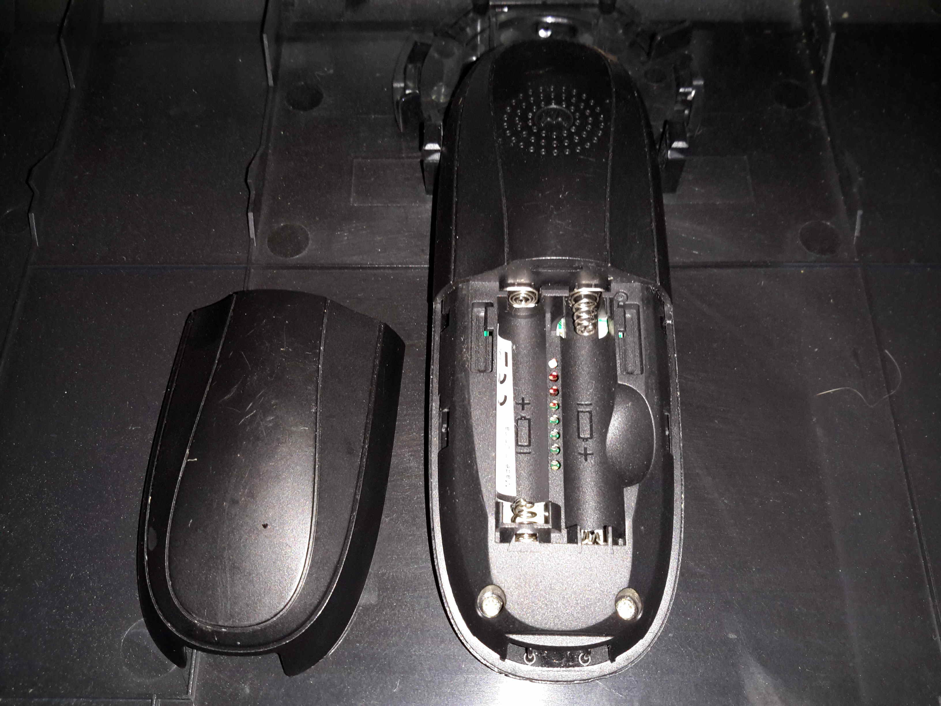
Here’s an old Motorola DECT landline phone, no use to me as I’ve not used a landline for many years.
Battery Compartment
Not much on the back, other than the battery compartment for a pair of AAA rechargables. The base unit contains the charger.
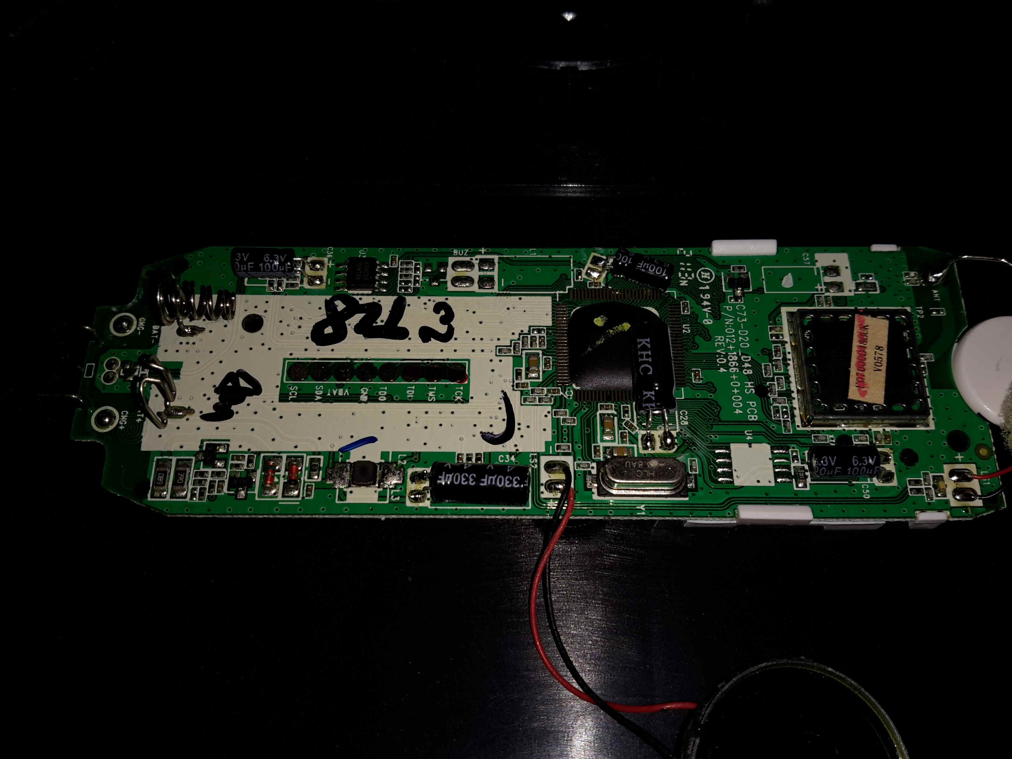
Main PCB
Here’s the main PCB removed from it’s casing. There’s not really much going on, one of the main ICs, which is probably a microcontroller, is a COB device, so no part numbers from there. There’s a row of pads for programming the device at the factory. The RF section is on a dedicated IC, a DE19RF19ZCNC from DSP Group. I couldn’t find much on this part, but it’s one of a range of DECT/VoIP DSP devices.
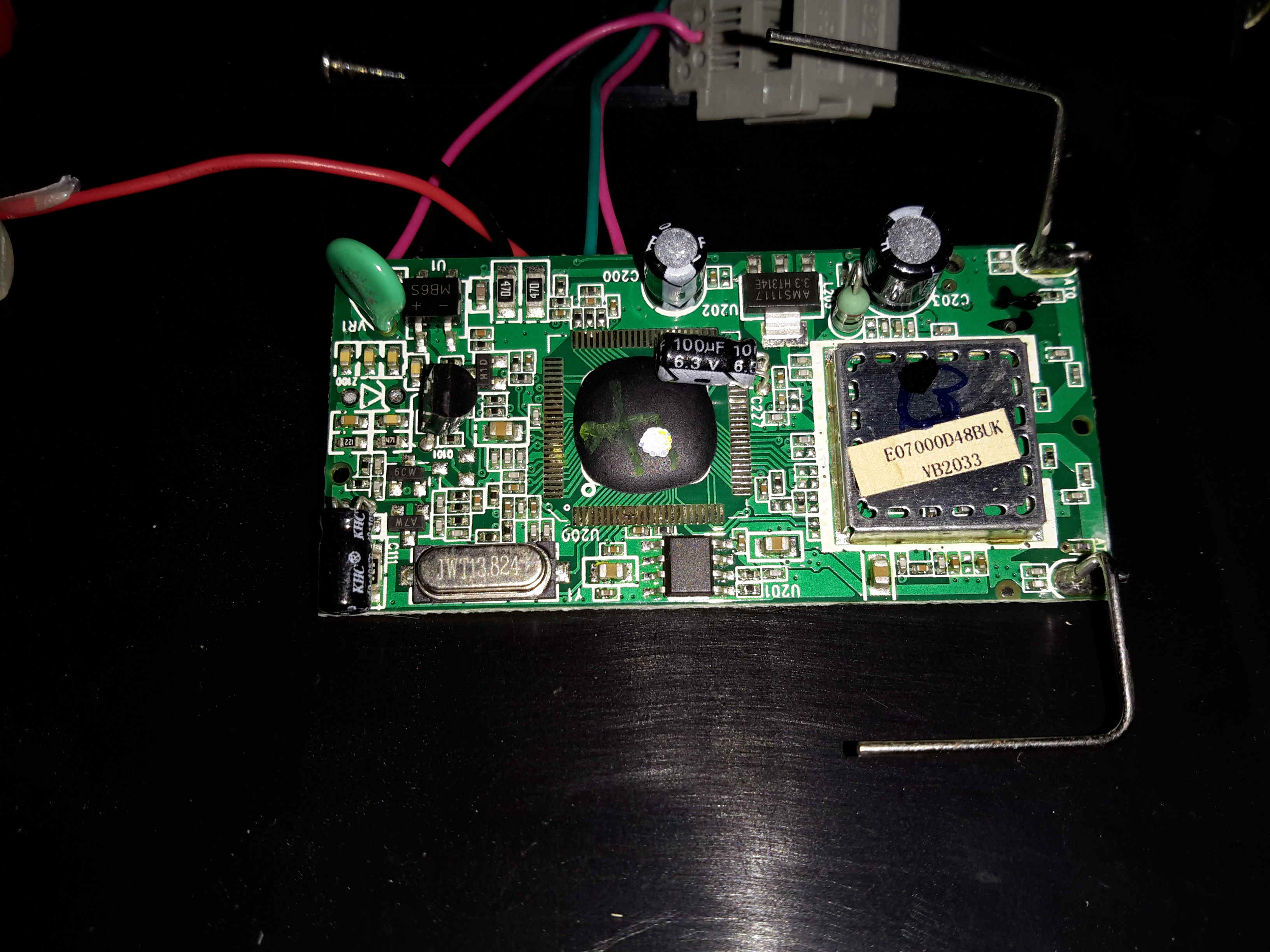
Base Unit PCB
Inside the base unit is a similar board, just without the keypad. Main microcontroller is again a COB device, the RF IC is under the shield.
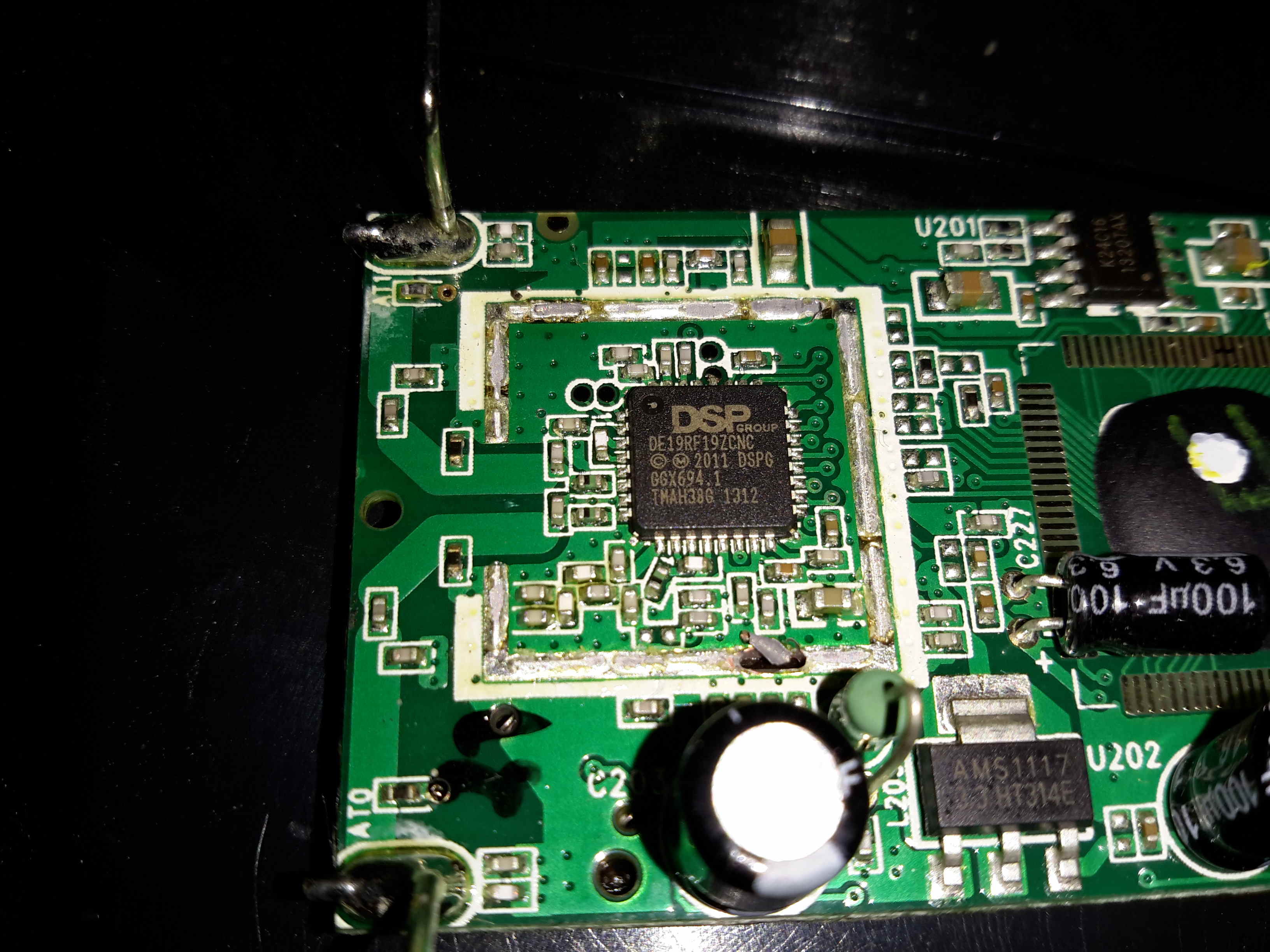
Main Chipset
Removing the shield reveals the same IC as in the handset, only this PCB has a pair of antennas.
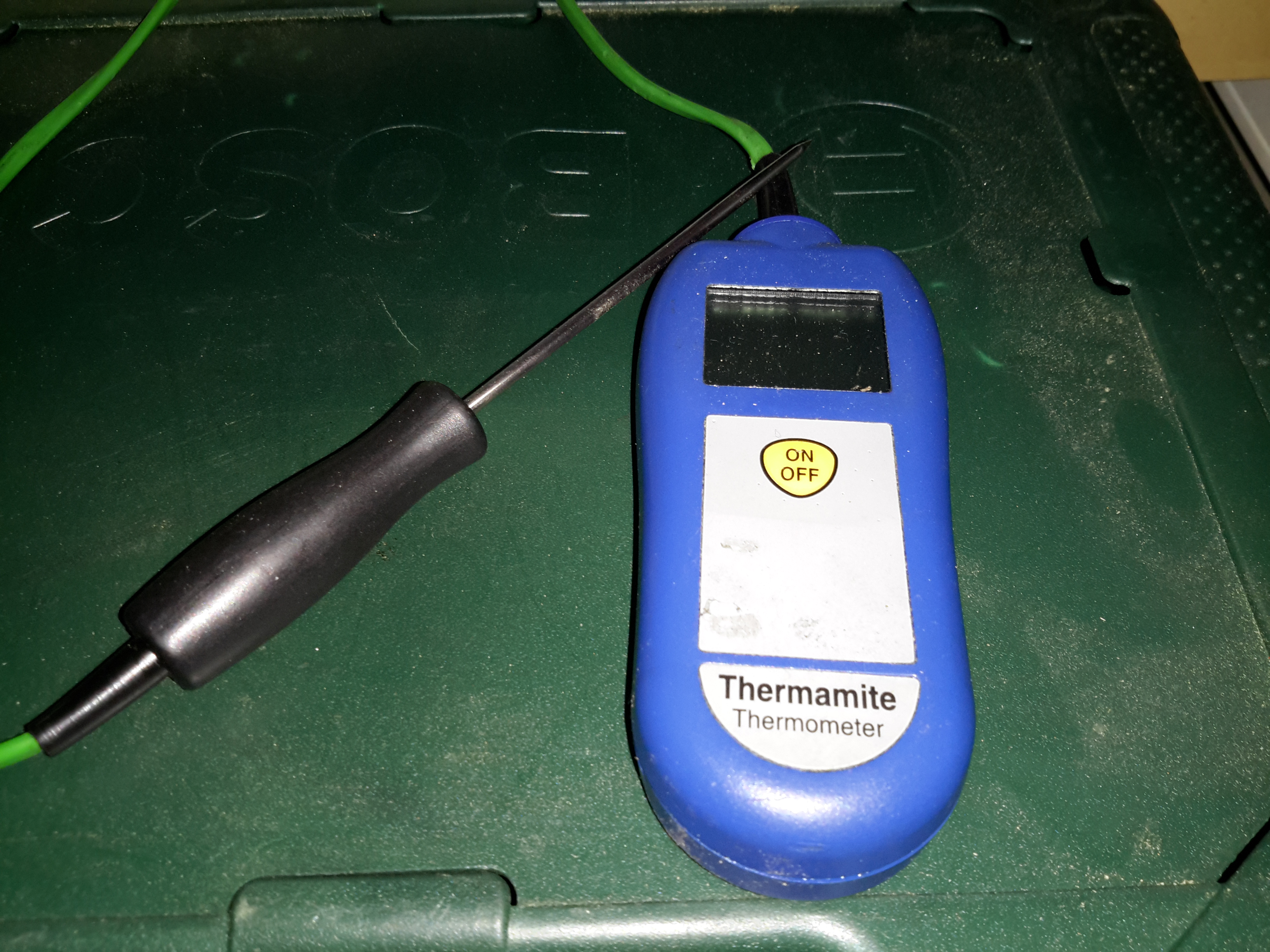
Here’s another bit of commercial gear, a catering thermometer. These are used to check the internal temperature of foods such as meat, to ensure they’re cooked through.
This was given to me with some damage, the battery cover is missing & the plastic casing itself is cracked.
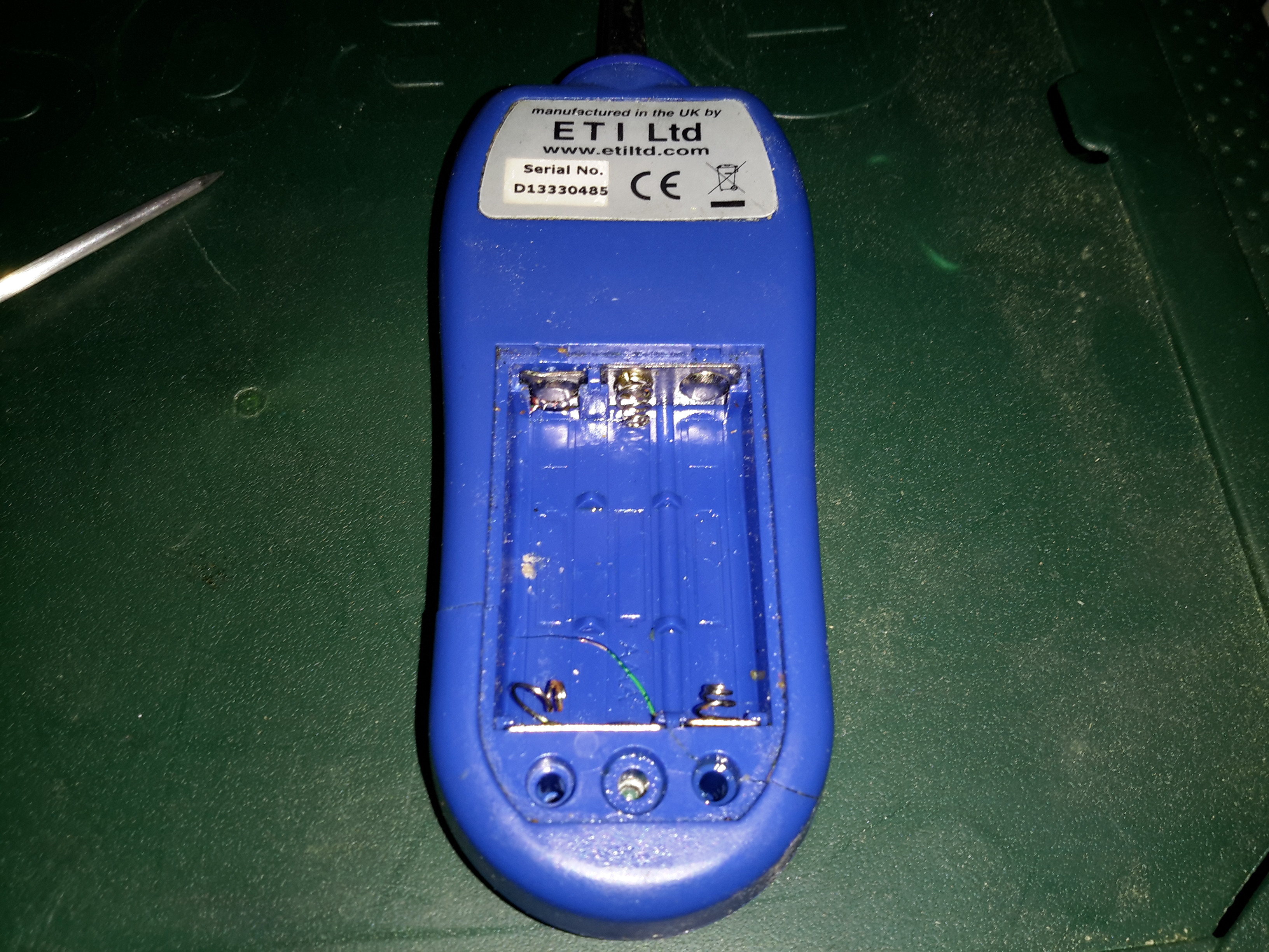
Battery Compartment
Power is provided by 3 AAA cells, for 4.5v
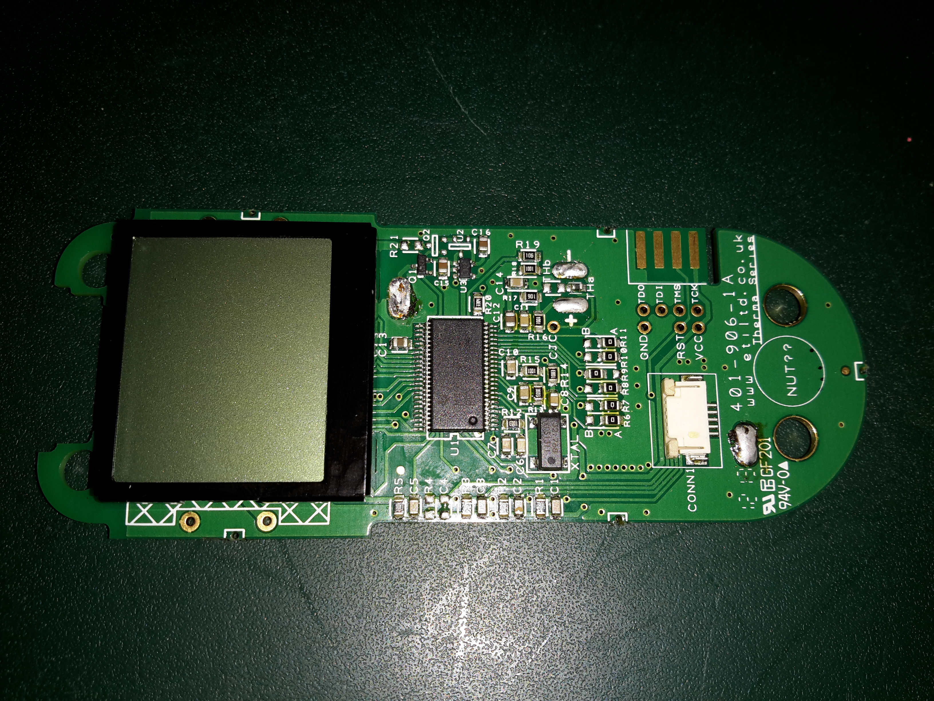
Main PCB
There’s not much to these units, the large LCD at the top is driven by the IC in the centre. A programming header is also present on the board near the edge.
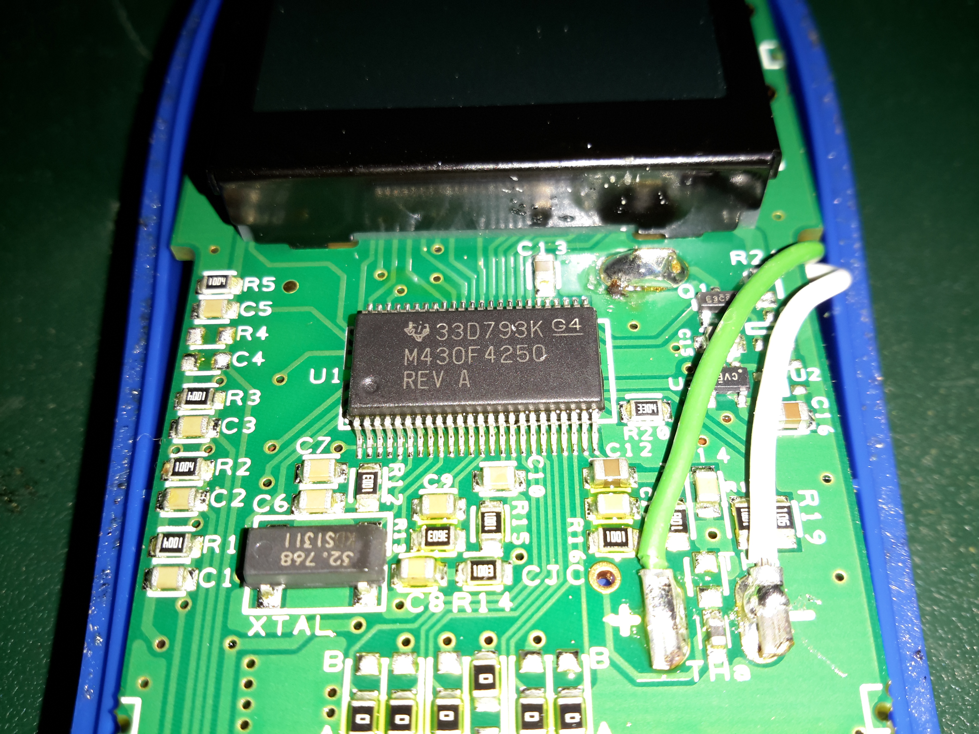
Microcontroller
The core logic is taken care of with a Texas Instruments M430F4250 MSP430 Mixed-Signal Microcontroller. This MCU has onboard 16-bit Sigma-Delta A/D converter, 16-bit D/A converter & LCD driver. Clock is provided by a 32.768kHz crystal.
The probe itself is just a simple thermistor bonded into a stainless steel rod.
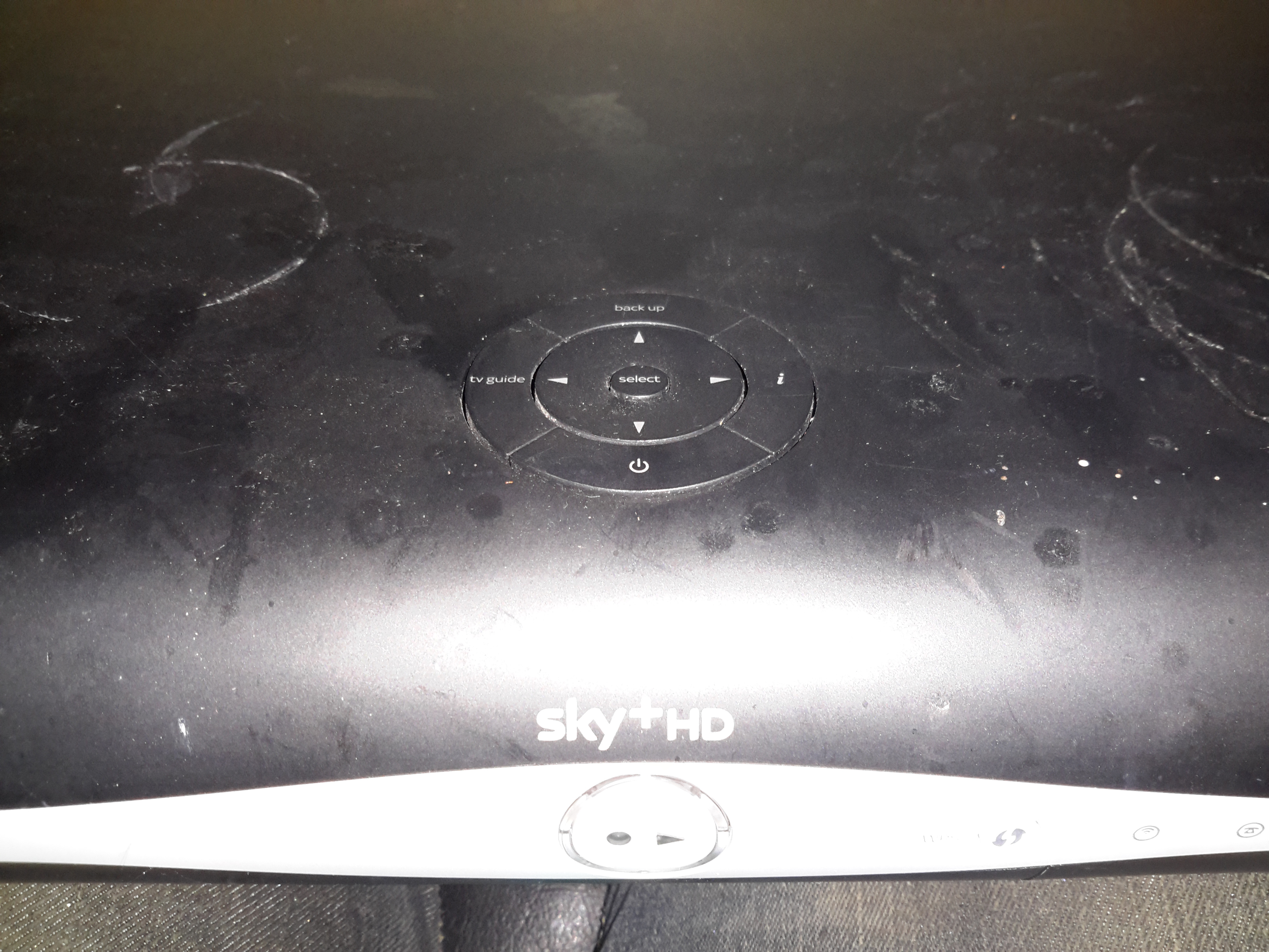
Time for another teardown! I managed to fish this Sky+ box out of a skip, but to protect the guilty, all serial numbers have been removed.
These are pretty smart devices, with DVR capability on board.
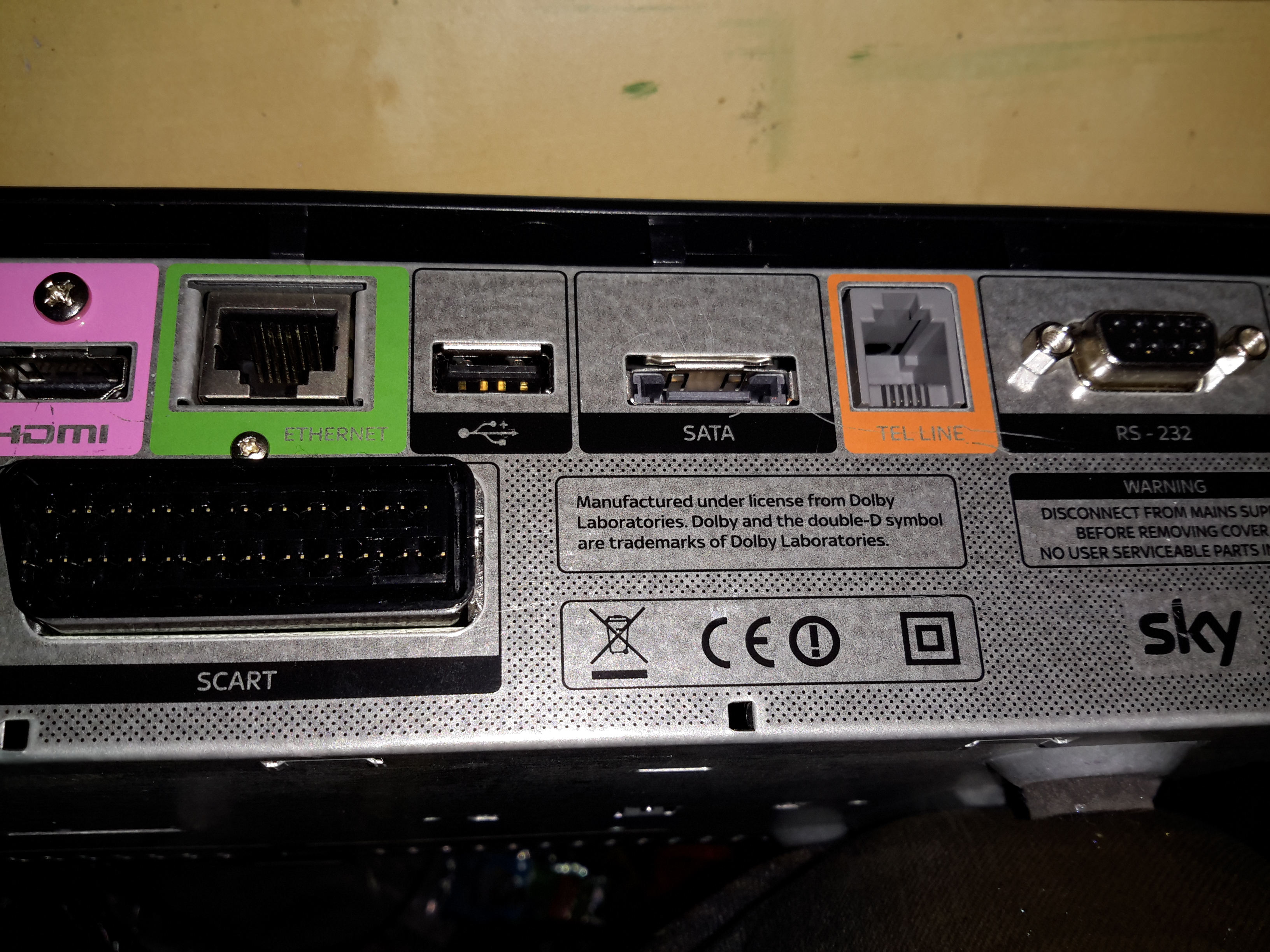
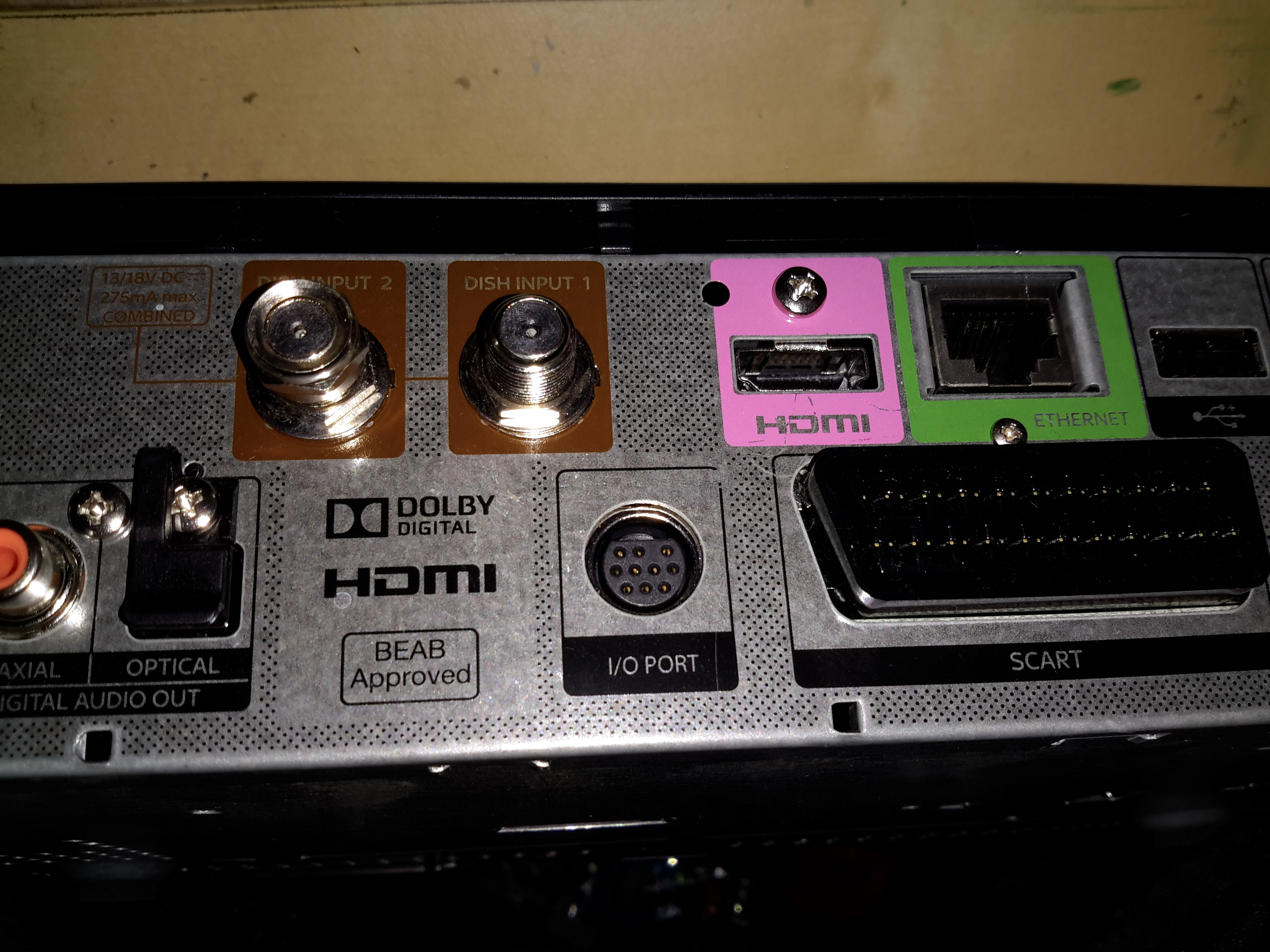
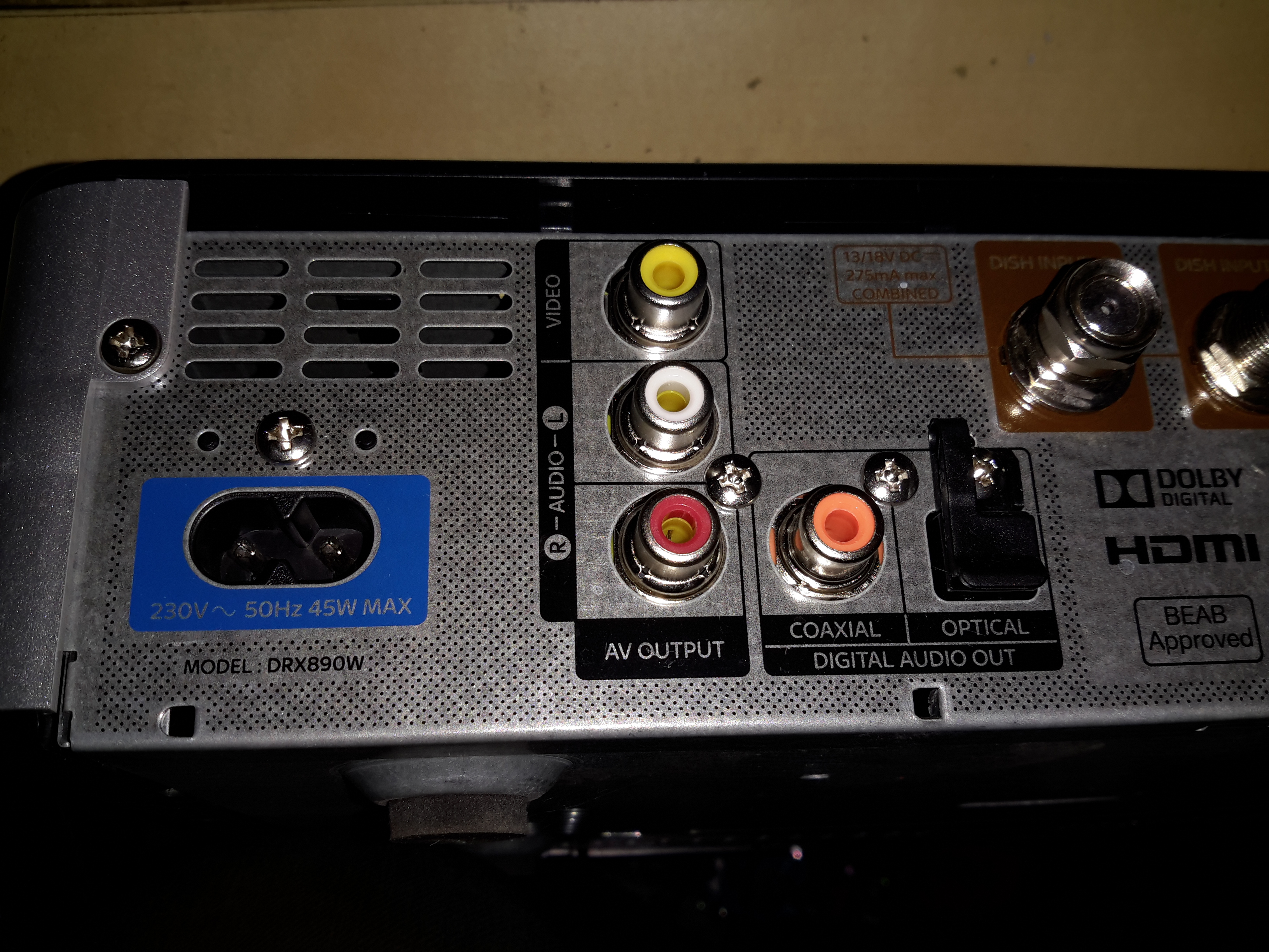
Ports 1
There’s a lot of ports on these units, from RS-232 serial, POTS modem, eSATA, HDMI, USB, Ethernet, SCART, Optical, digital outputs & even composite video.
Ports 2Ports 3Top Panel
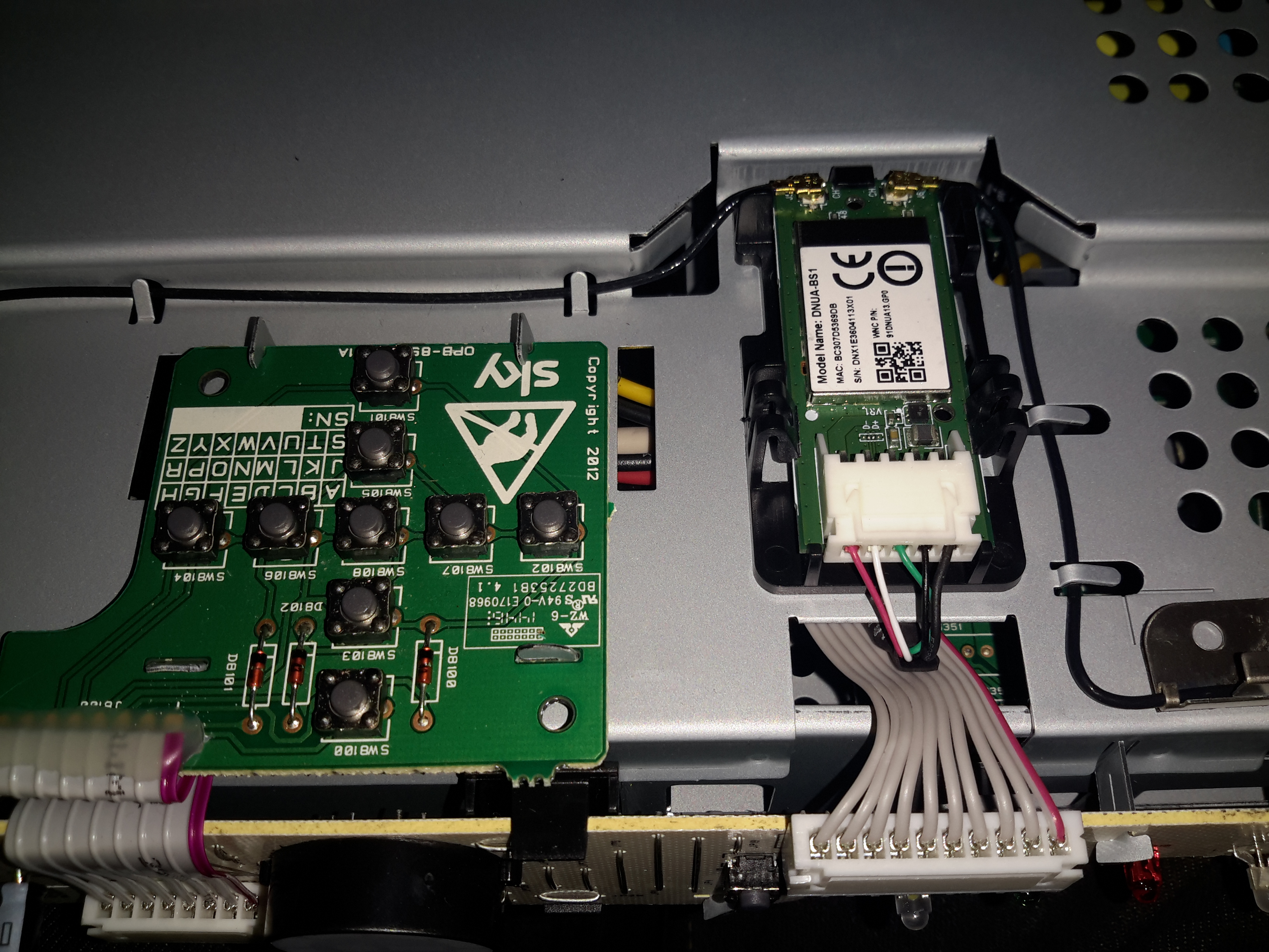
Removing the top plastic cover reveals the operation buttons & the built in WiFi adaptor, which is USB connected to the main logic board.
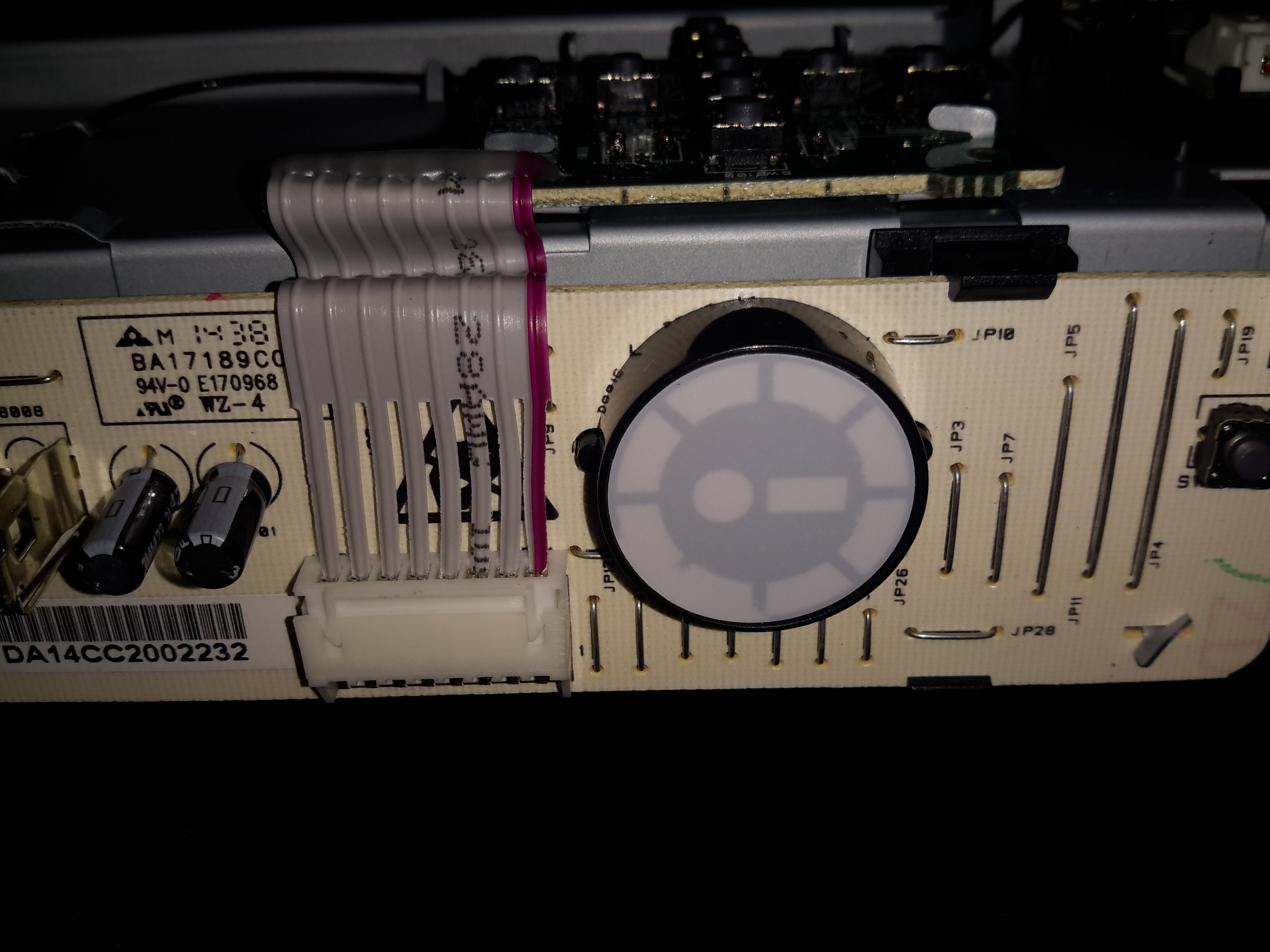
Front Panel
The PCB on the front of the chassis has all the indicators, and the IR Receiver for the remote.
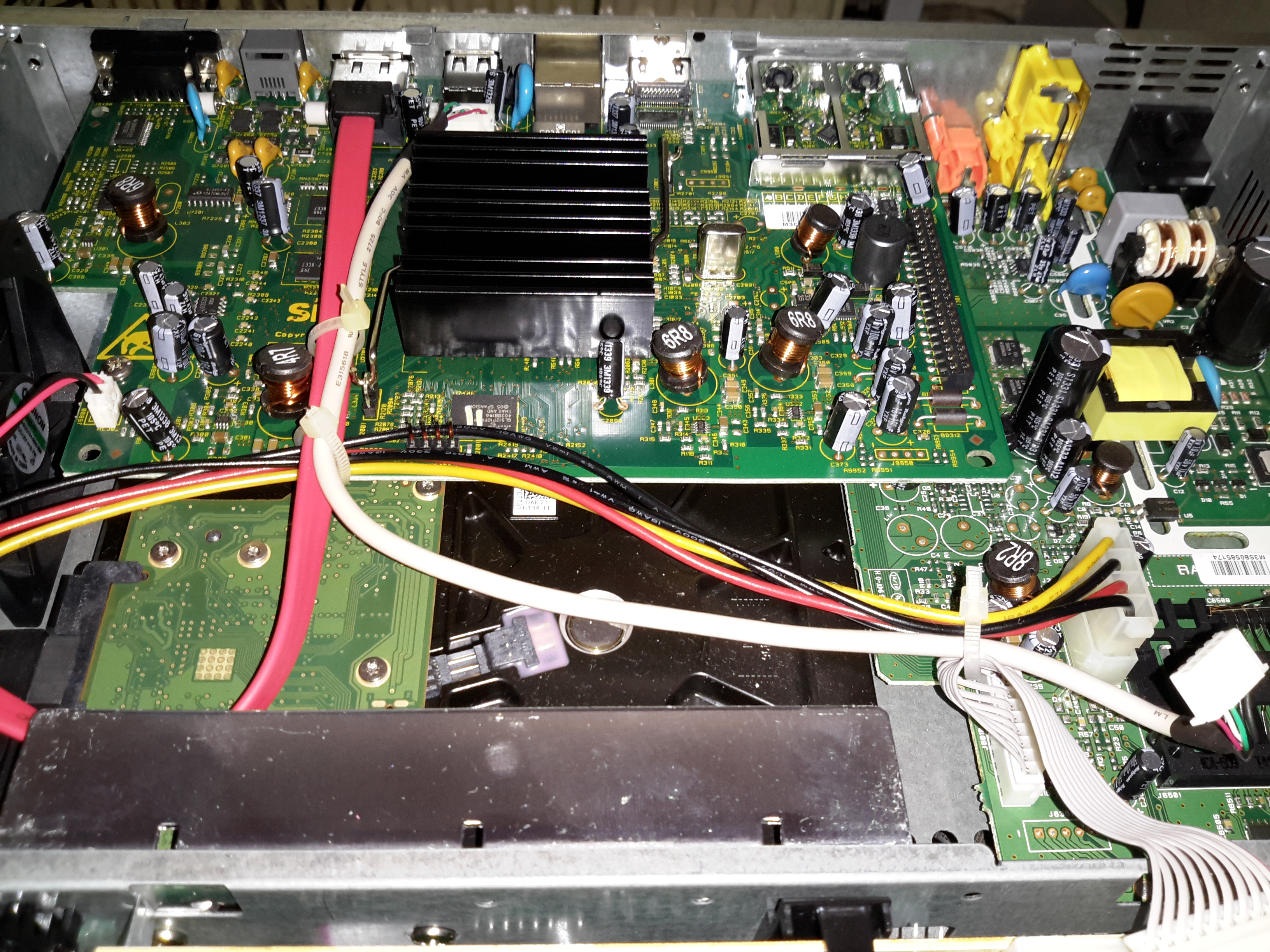
Cover Removed
Removing the top shield of the chassis reveals the innards. The PSU is on the top right, 500GB SATA disk drive in the bottom centre. The main logic PCB is top centre.
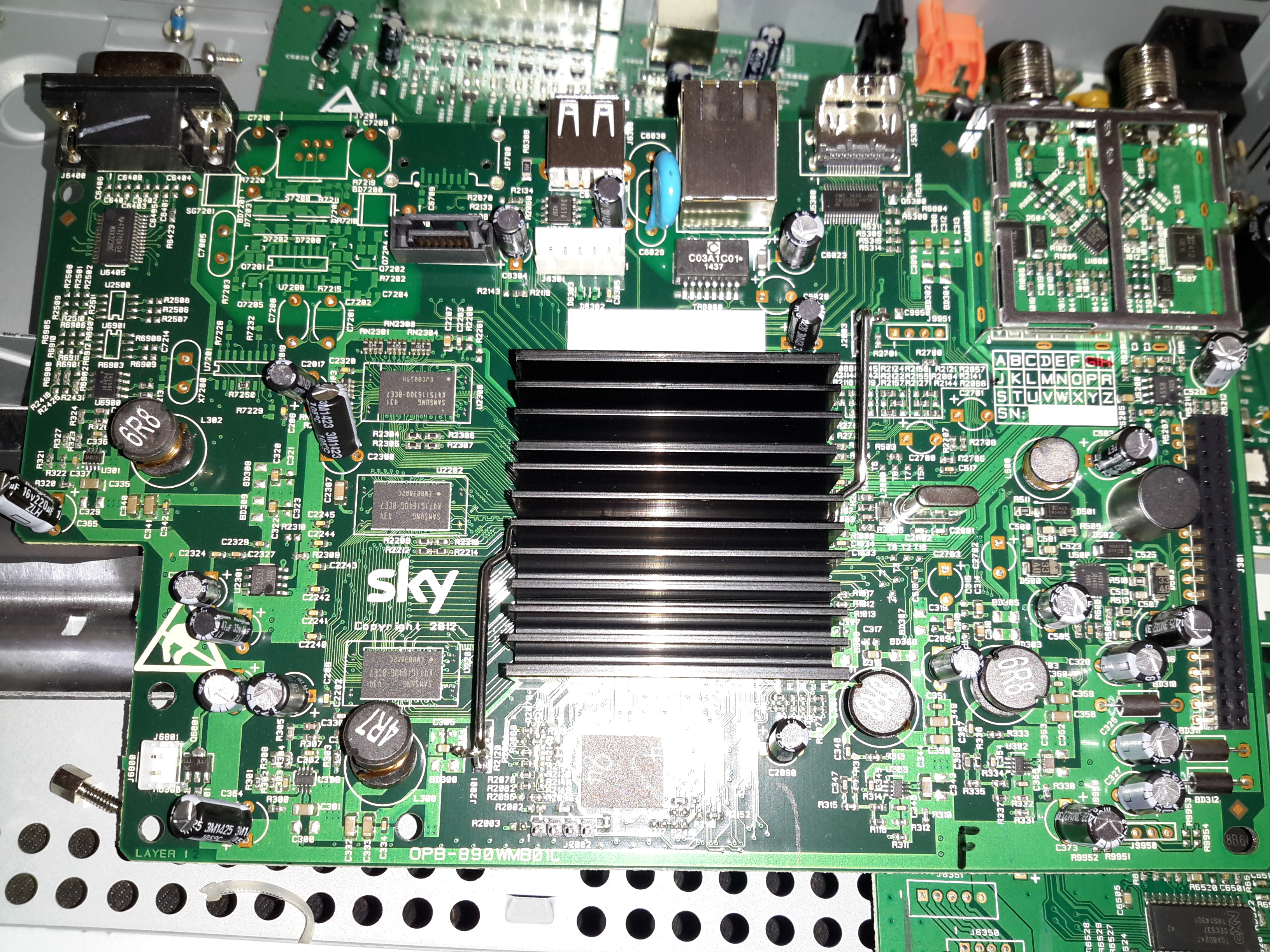
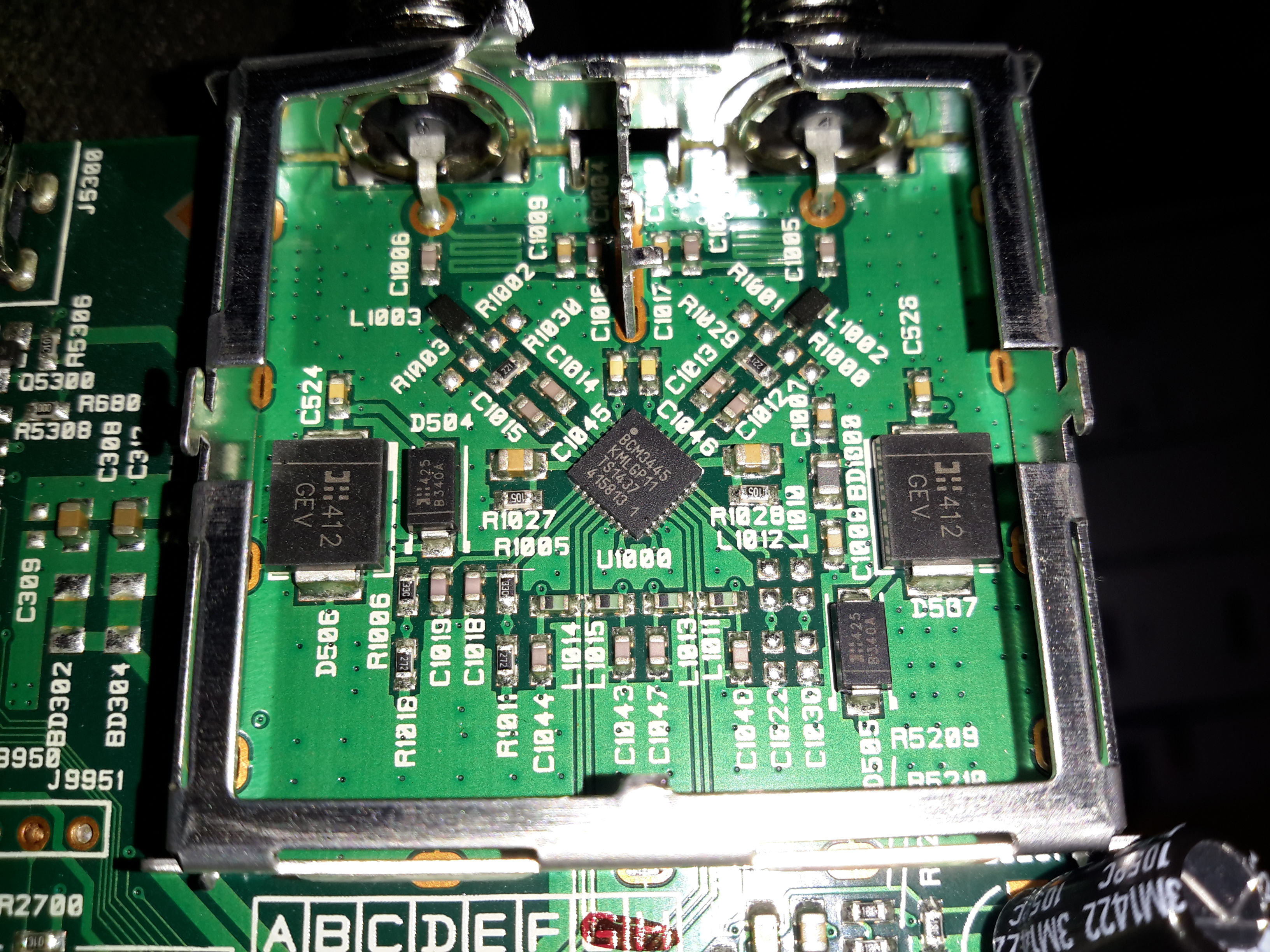
Logic PCB
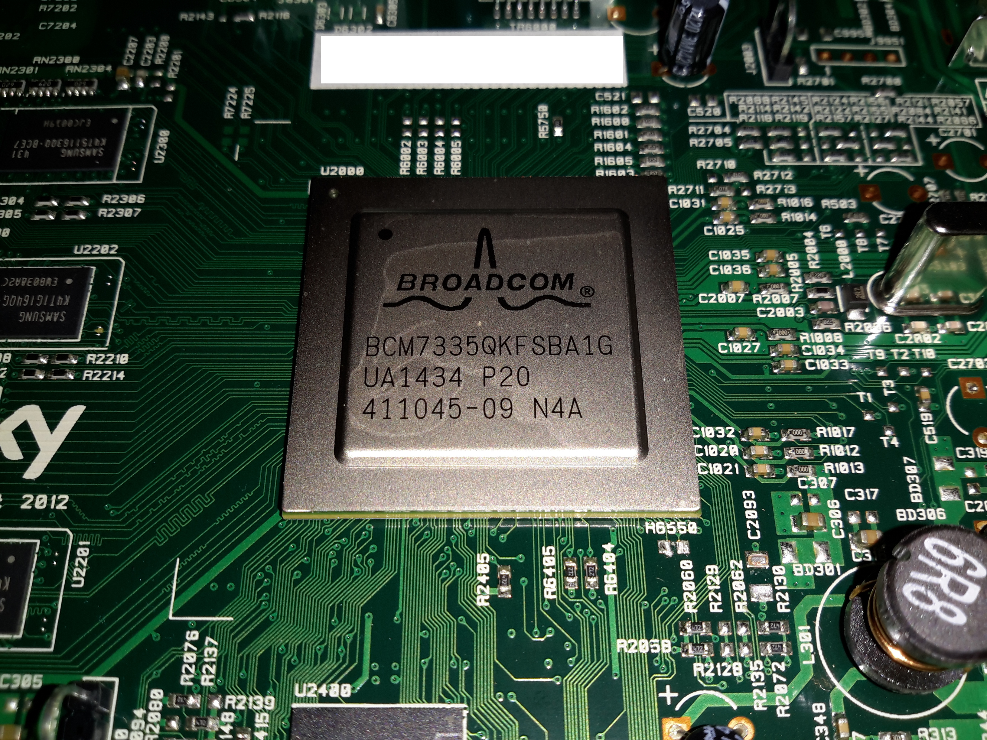
Here’s the main logic PCB. The massive heatsink in the middle is cooling the main SoC, below.
SoC
The main SoC in this unit is a Broadcom BCM7335 HD PVR Satellite System-On-Chip. It’s surrounded by it’s boot flash, a Spansion GL512P10FFCR1 512Mbit NOR device. It’s also got some DRAM around the left edge.
Smart Card Reader
The smart card reader is on the PSU PCB, the controller here is an NXP TDA8024
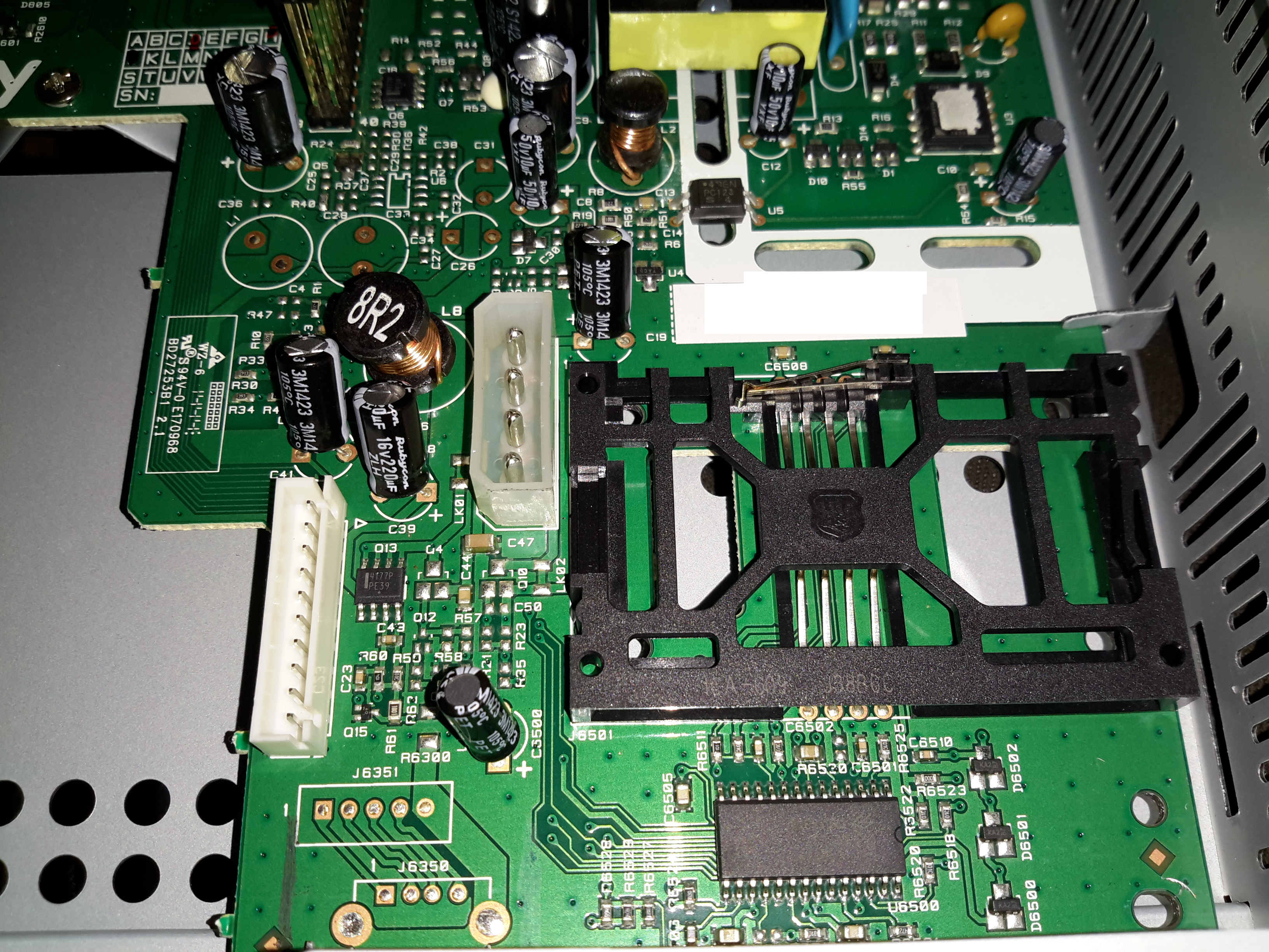
PSU PCB
The PSU itself is a pretty standard SMPS, so I won’t go too far into that particular bit. The logic PCB attaches to the large pin header on the left of the PSU, some of the analogue video outputs are also on this board.
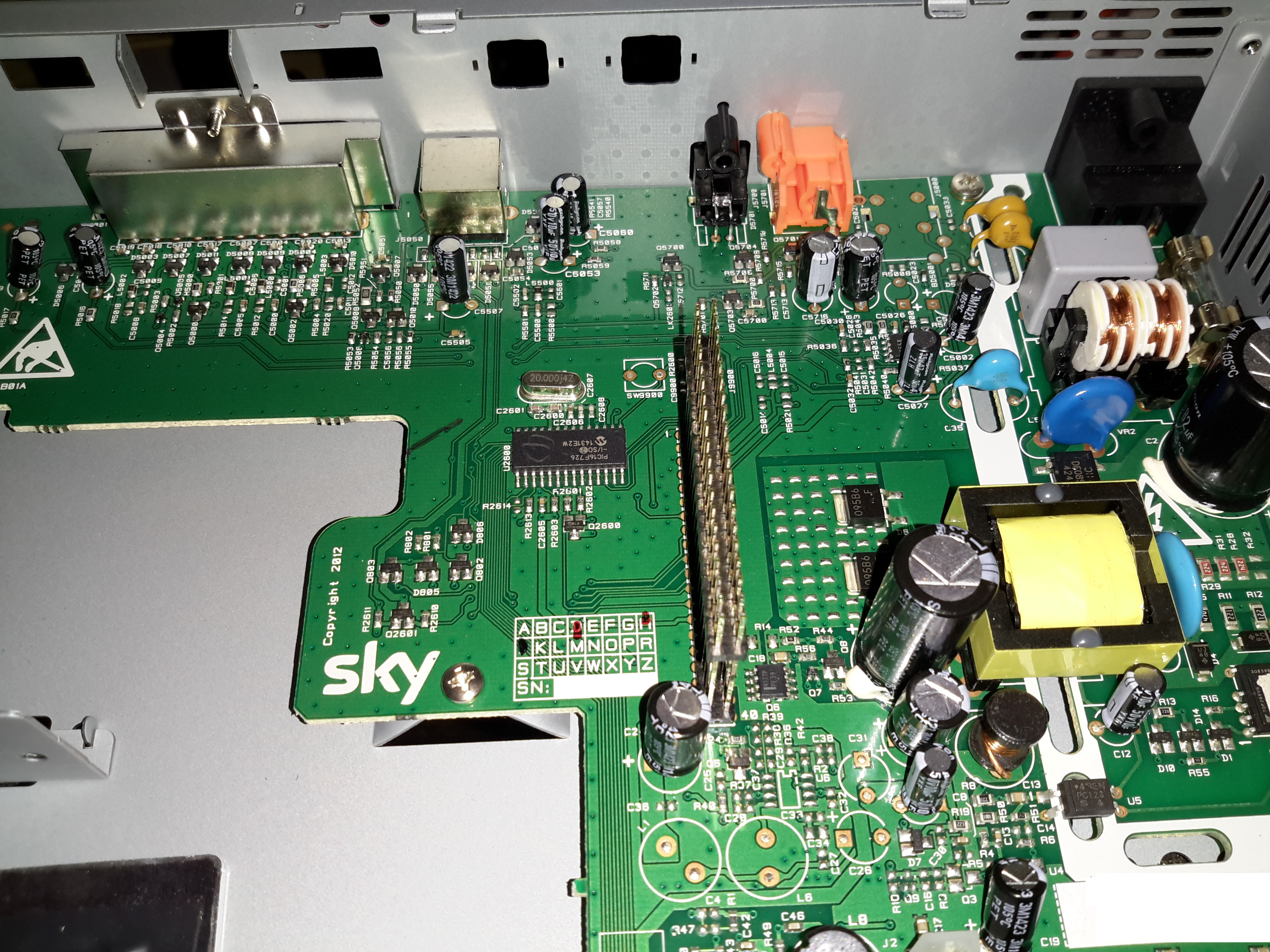
There’s also a Microchip PIC16F726 microcontroller on this PCB, next to the pin header. Judging by the PCB traces, this handles everything on the user control panel.
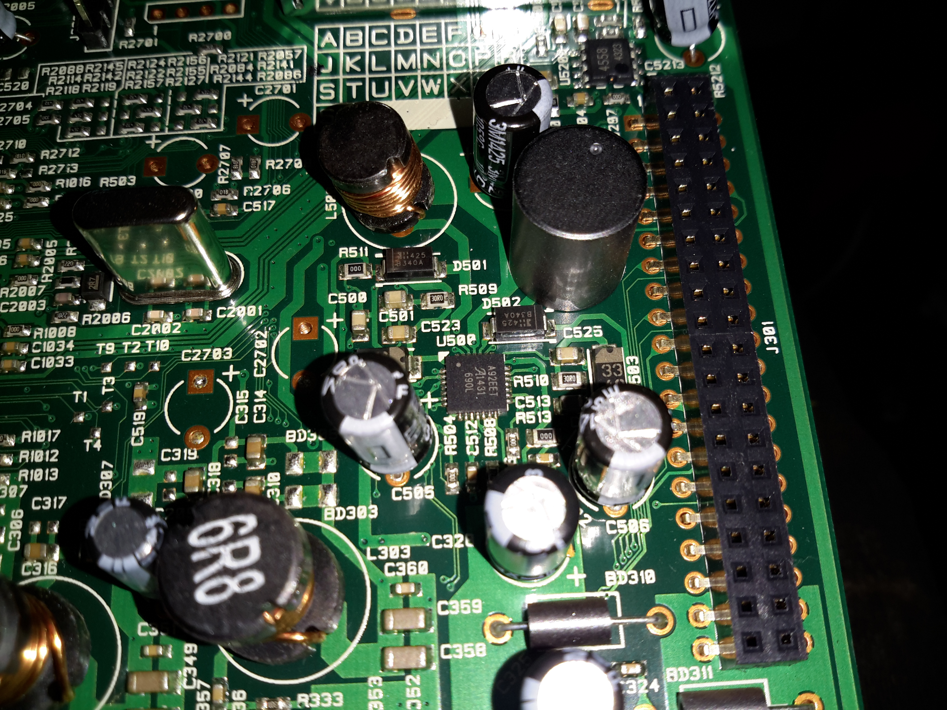
Power Supplies
Some local supplies are provided on the logic board for the main SoC, the IC in the centre here is an Allegro A92 DC-DC converter. I didn’t manage to find a datasheet for this one.
LNB Front End
The RF front end for the satellite input is a Broadcom BCM3445 Low Noise Amplifier & Splitter, again not much info on this one.
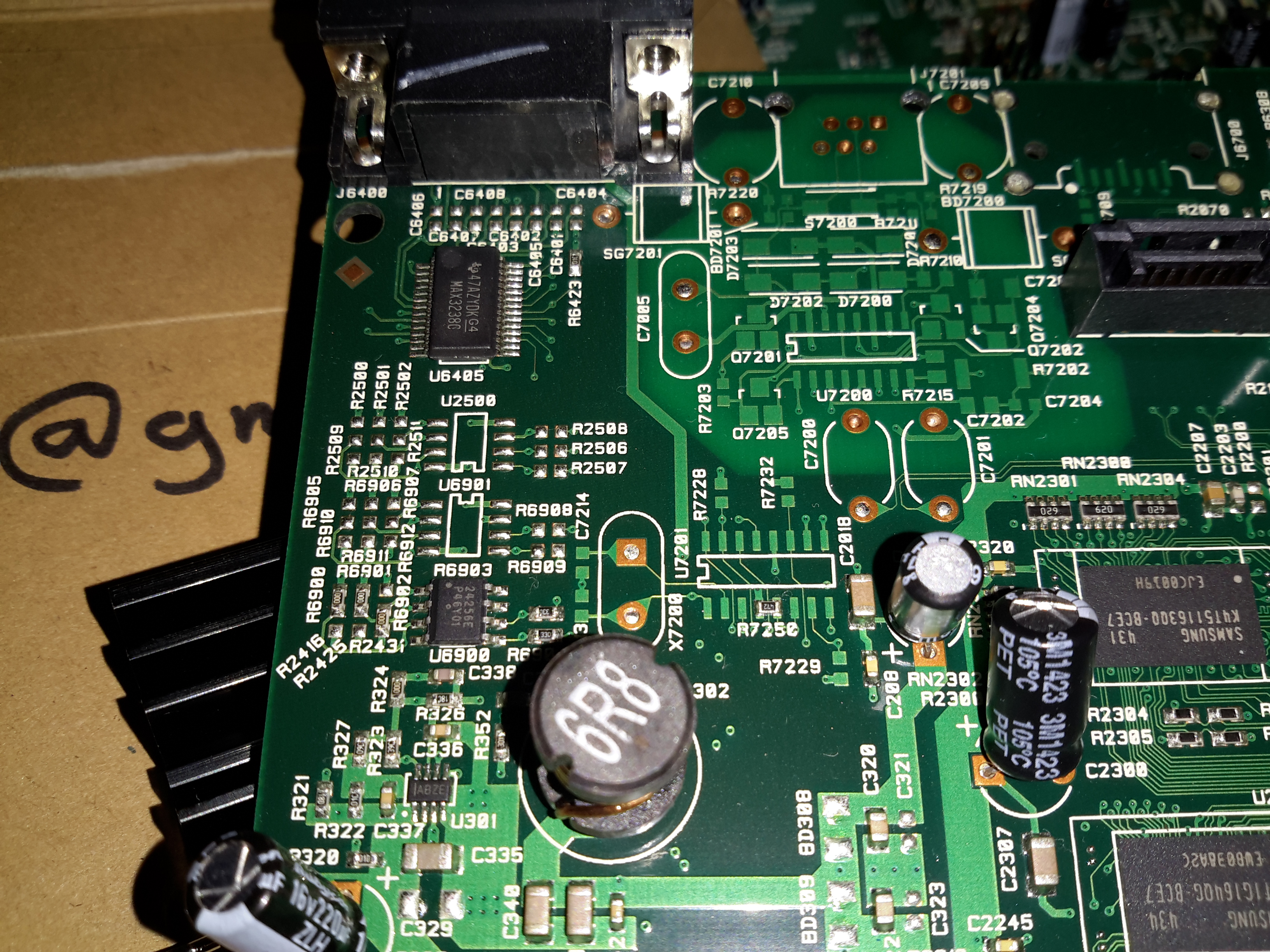
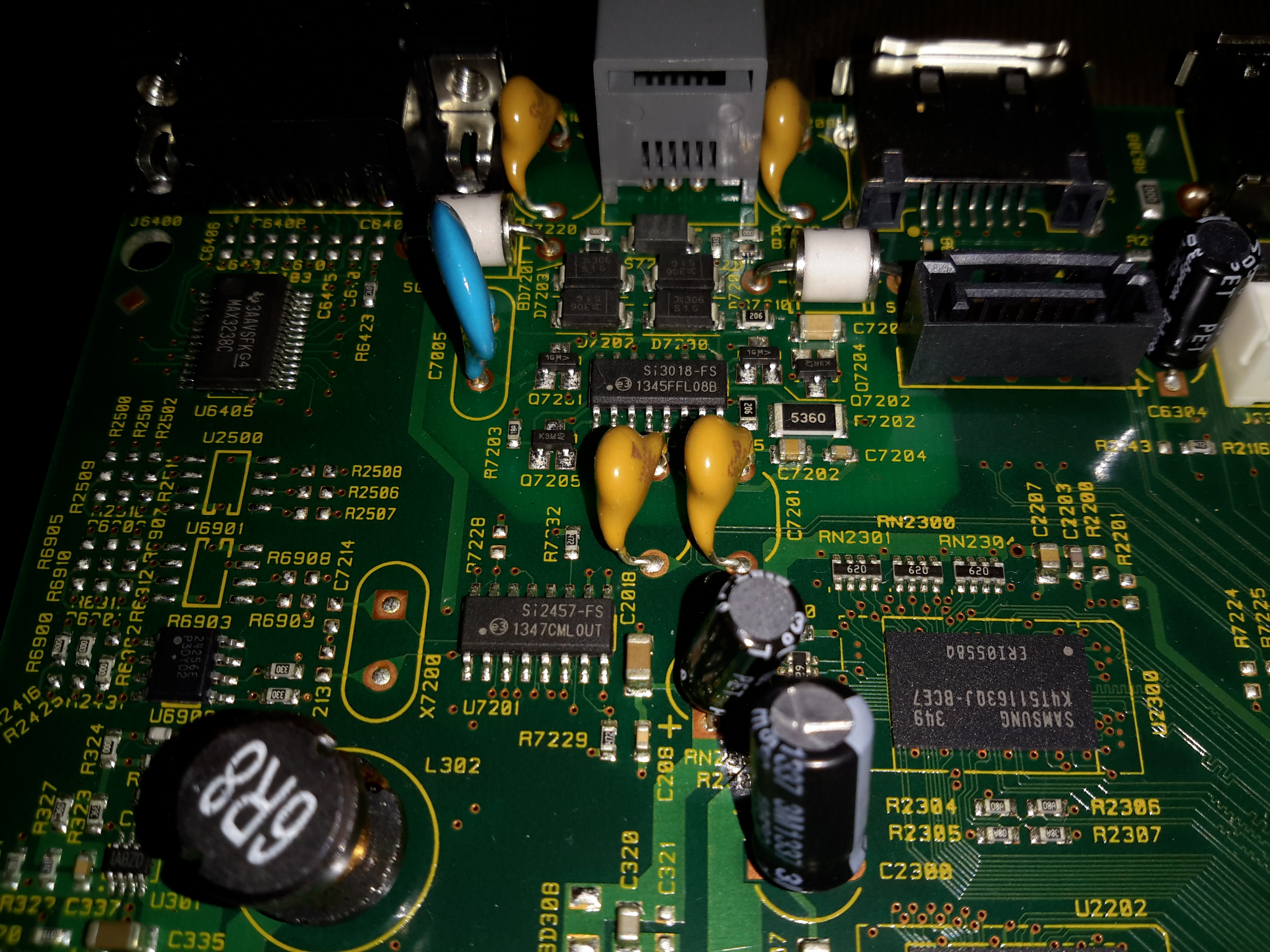
RS232 Section
The standard MAX232 is used for the serial interface. I imagine this is for diagnostics.
Modem
The POTS modem section is handled by a Si2457 System-Side device & Si3018 Line-Side device pair.
Going through eBay recently looking for parts for a couple of CRT-based projects, I came across these DC-DC converters.
Apparently rated from 45-390v DC output at 200mA, these should be ideal for driving some of the electrodes (focus, screen, grid) in a CRT.
Above is the top of the board, input voltage header on the left, output voltage adjust in the centre & output voltage header on the right.
This module has a mini-automotive fuse, at 10A for input protection.
On the heatsink is mounted the main switching MOSFET, a RU7088R from Ruichips. This FET is fairly heavily rated at 70v 80A, with 6.5mΩ on-resistance.
PCB Bottom
The bottom of the board has the control components, with a pair of ICs. Unfortunately the numbers have been scrubbed off, so no identification here. The output from the transformer is rectified with a single large SMD diode on the left side of the board.
There’s also plenty of isolation gap between the HV output trace & the low voltage logic side of the circuit, the two being bridged only by a resistive divider for output voltage measurement.
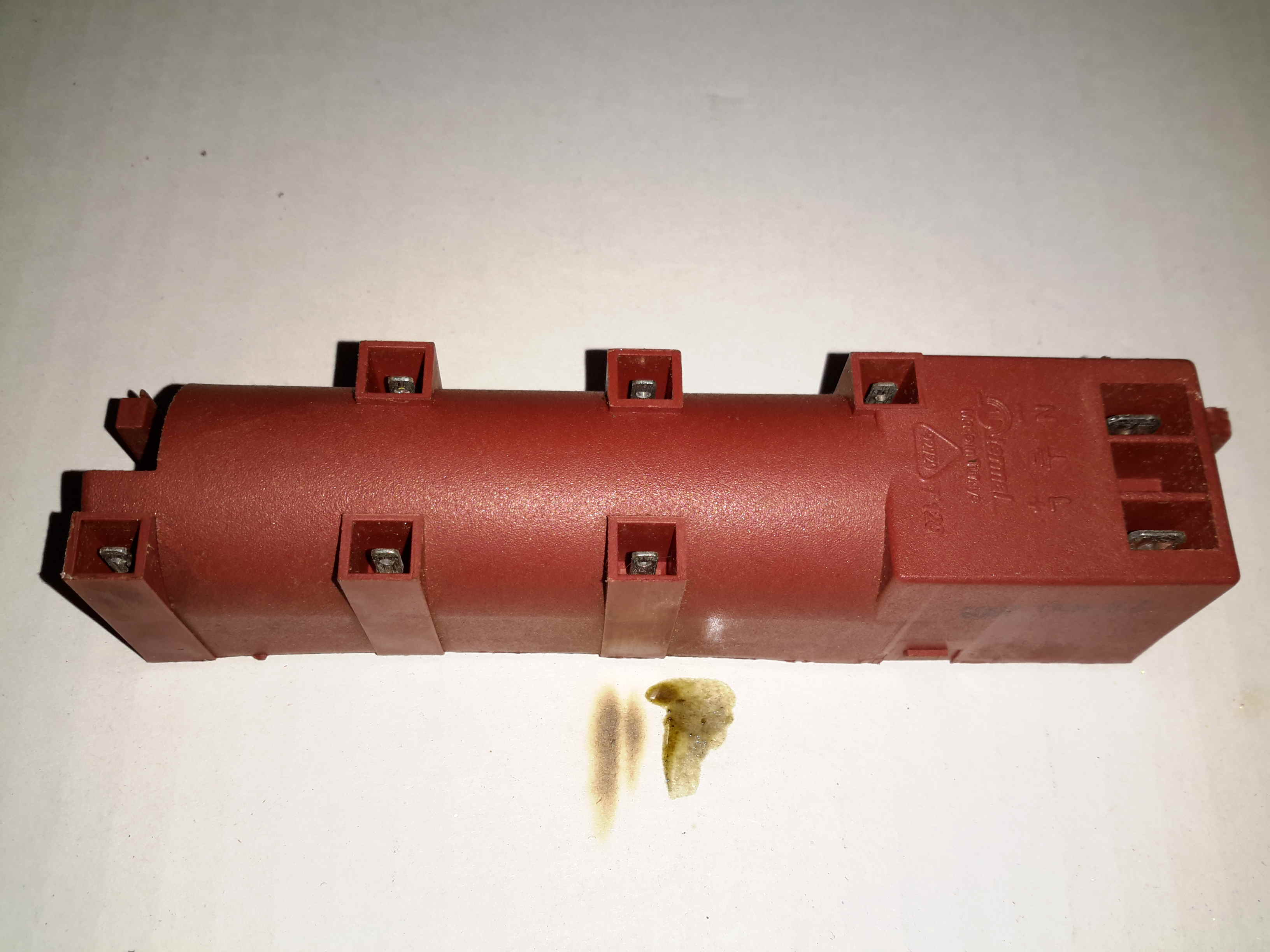
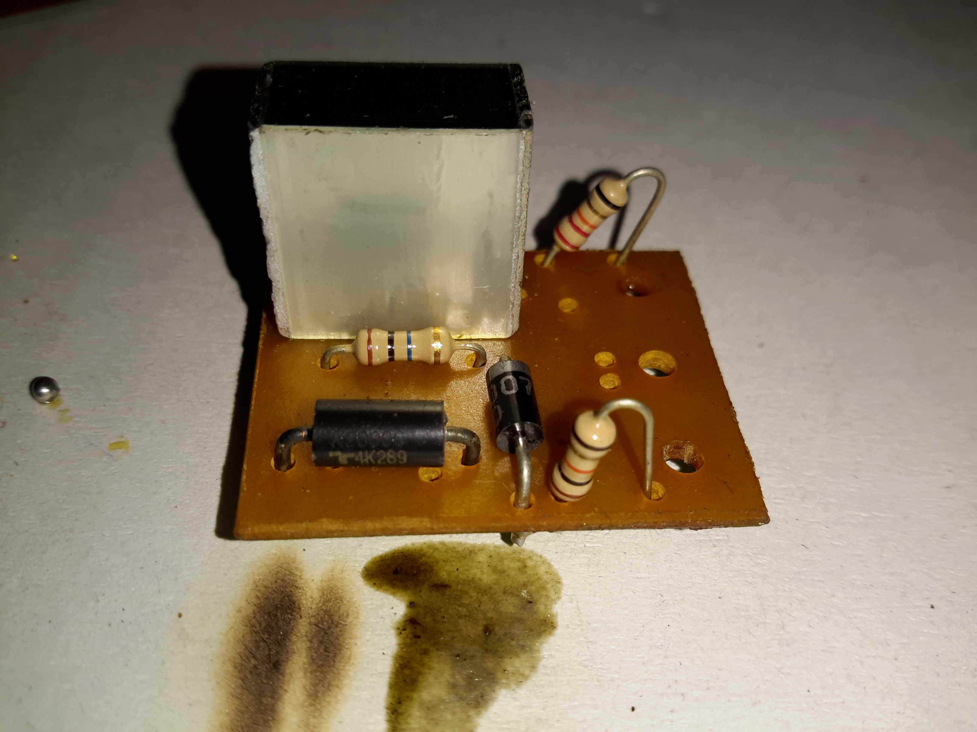
Here’s a quick teardown of an ignition transformer, used on gas fired ovens & hobs. This unit takes mains 240v AC & uses a transformer to step the voltage to several kV, at a low current to ignite the burners.
Bottom
The transformer section is completely potted in Epoxy resin for insulation, but the driver circuitry is exposed, with a pair of leads from the primary winding exposed
Driver PCB
The drive is very simple. The incoming AC flows through a series resistor through a half-wave rectifier to charge up a 2.2µF film capacitor. Once the voltage on the capacitor reaches a certain level, a DIAC in series with the transformer primary fires, discharging the capacitor through the primary.
The current spike induces a very high voltage on the secondary winding, this then arcs across a gap in the gas flow to start ignition.
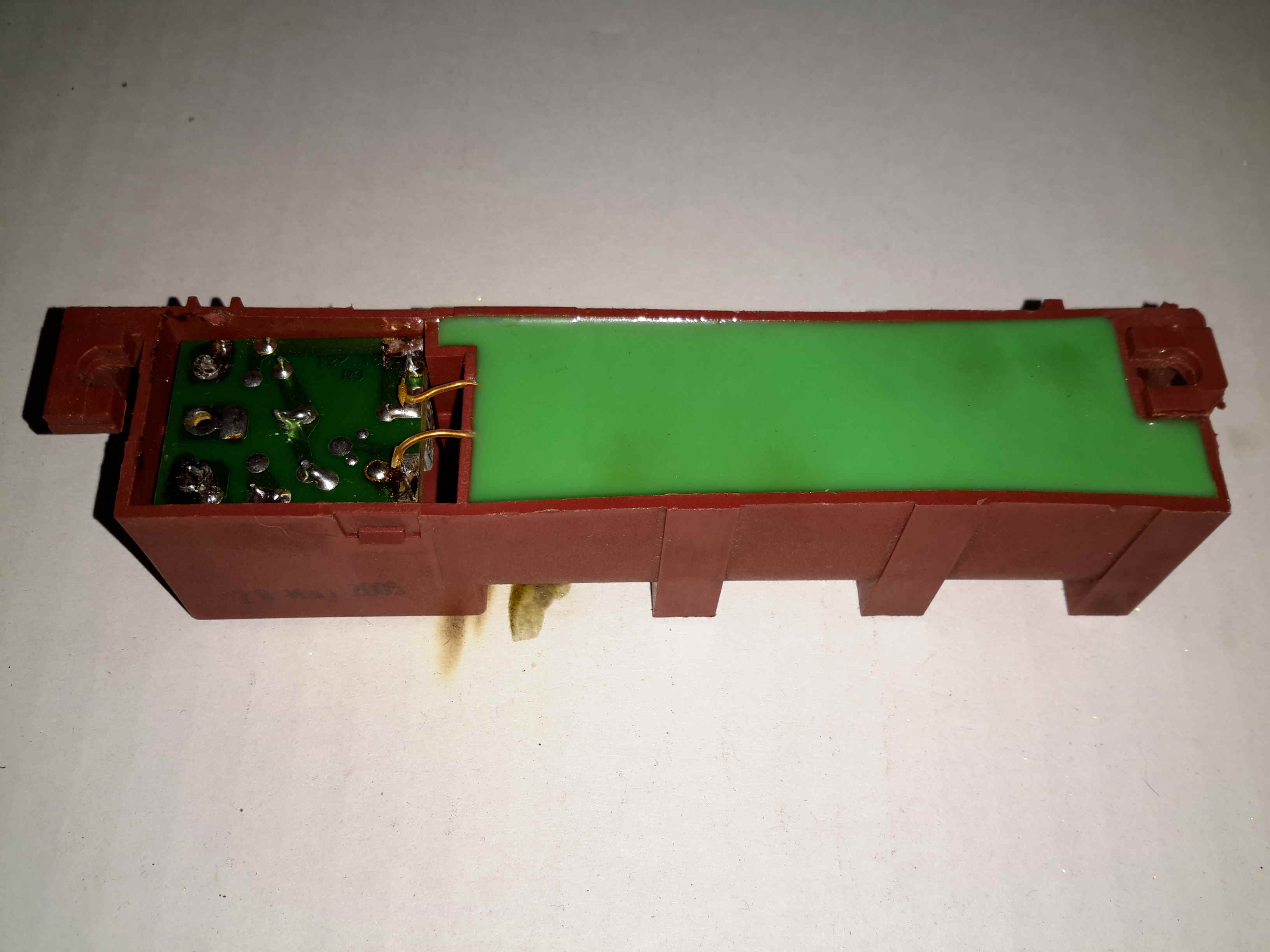
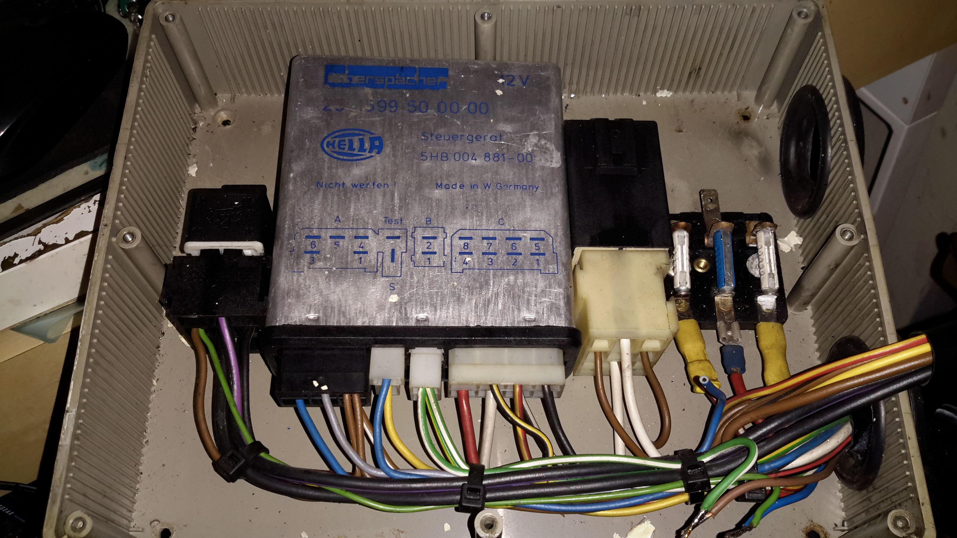
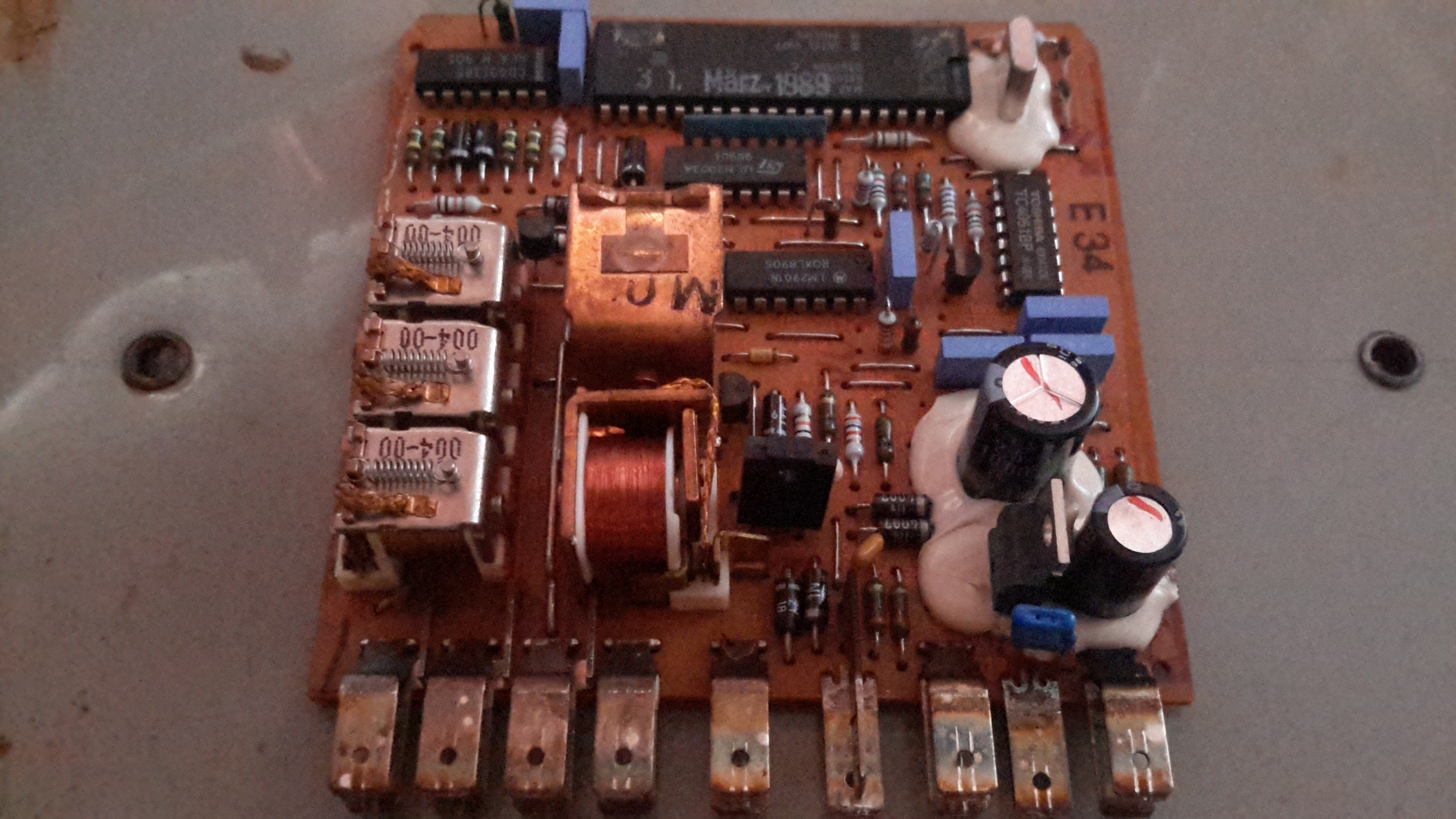
Here’s another Eberspacher control unit, this time from an ancient D5W 5kW water heater. The system in this case is just flaky – sometimes the heater will start without fault & run perfectly, then suddenly will stop working entirely.
The error codes are read on these very old units via an indicator lamp connected to a test terminal. In this case the code was the one for Overheat Shutdown.
Considering this fault occurs when the heater is stone cold, I figured it was either a fault with the sensor itself or the ECU.
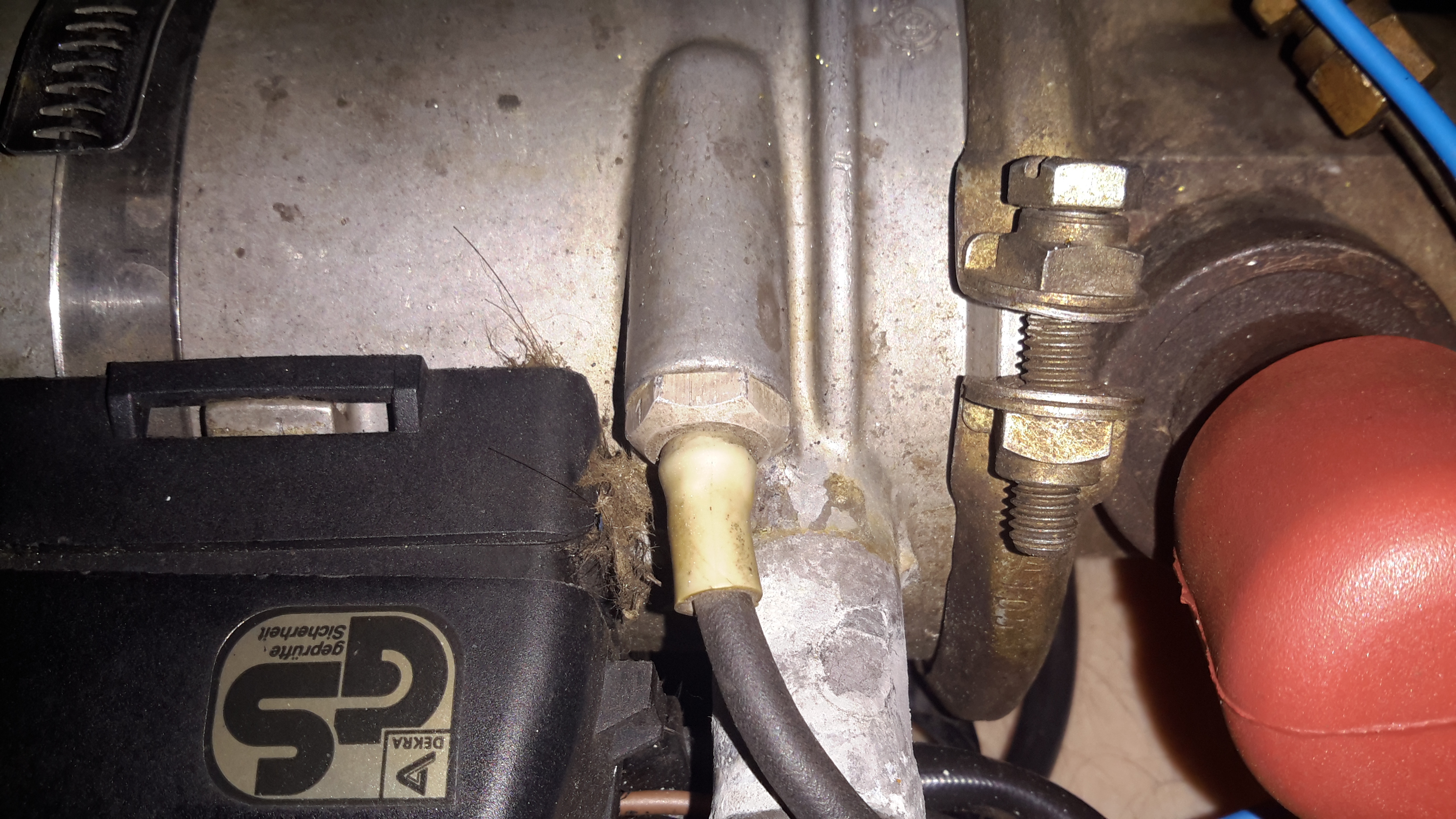
Temperature Sensor
The temperature sensor is located on the heat exchanger, right next to the hot water outlet fitting. I’m not sure what the spec is, but it reads exactly 1KΩ at room temperature.
ECU PCB
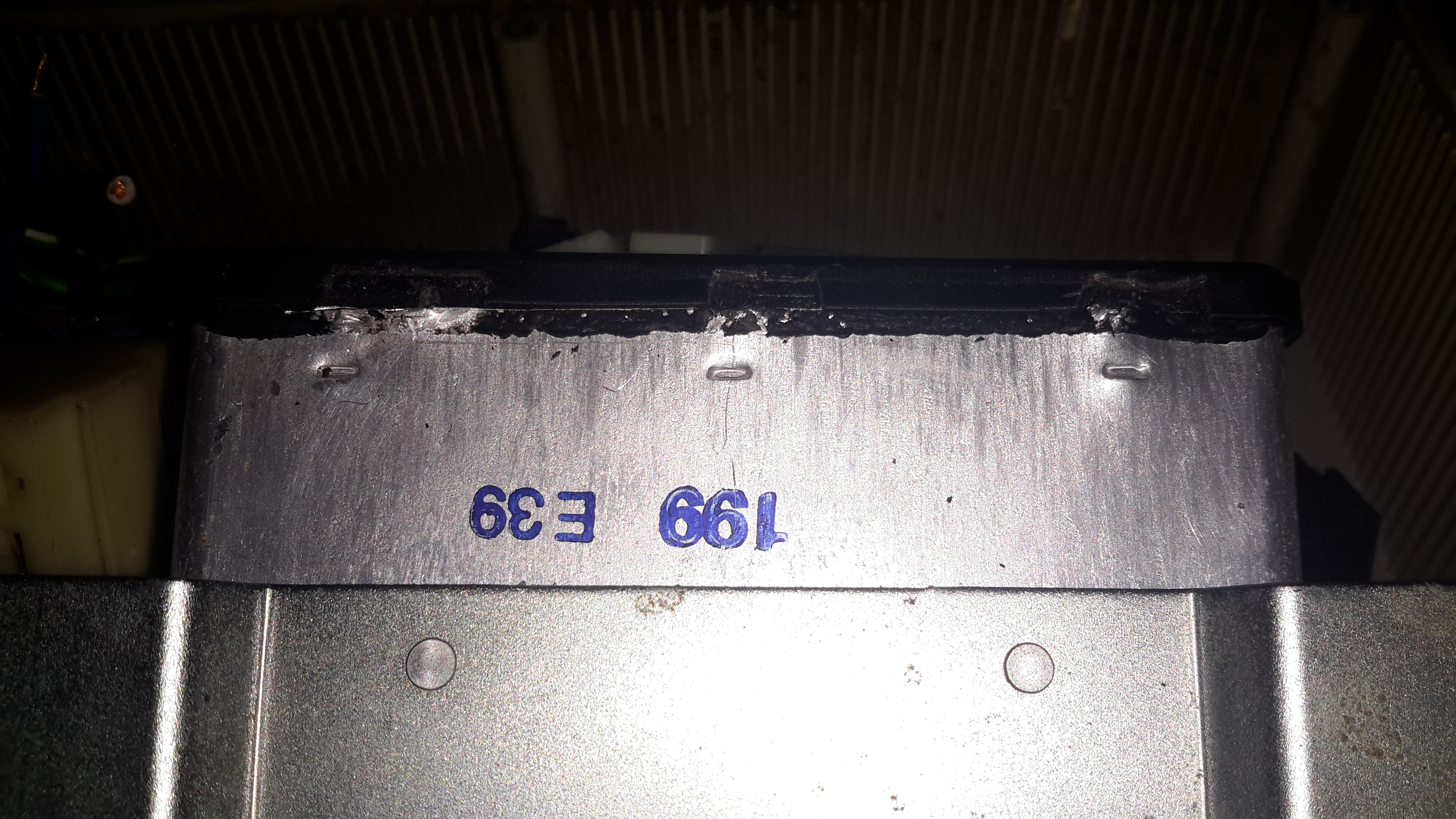
The PCB is held into the aluminium can by means of crimps around the edge that lock into the plastic terminal cover. Inserting a screwdriver & expanding the crimps allows the PCB to be slid out.
Casing Crimps
The factory date stamp on the microcontroller dates this unit to March 1989 – considerably older than I expected!
Unlike the newer versions that use transistors, this ECU has a bunch of PCB relays to do the high current switching of the water pump motor, fan motor & glowplug.
Overall the board looks to be solidly constructed, with silicone around all the larger components.
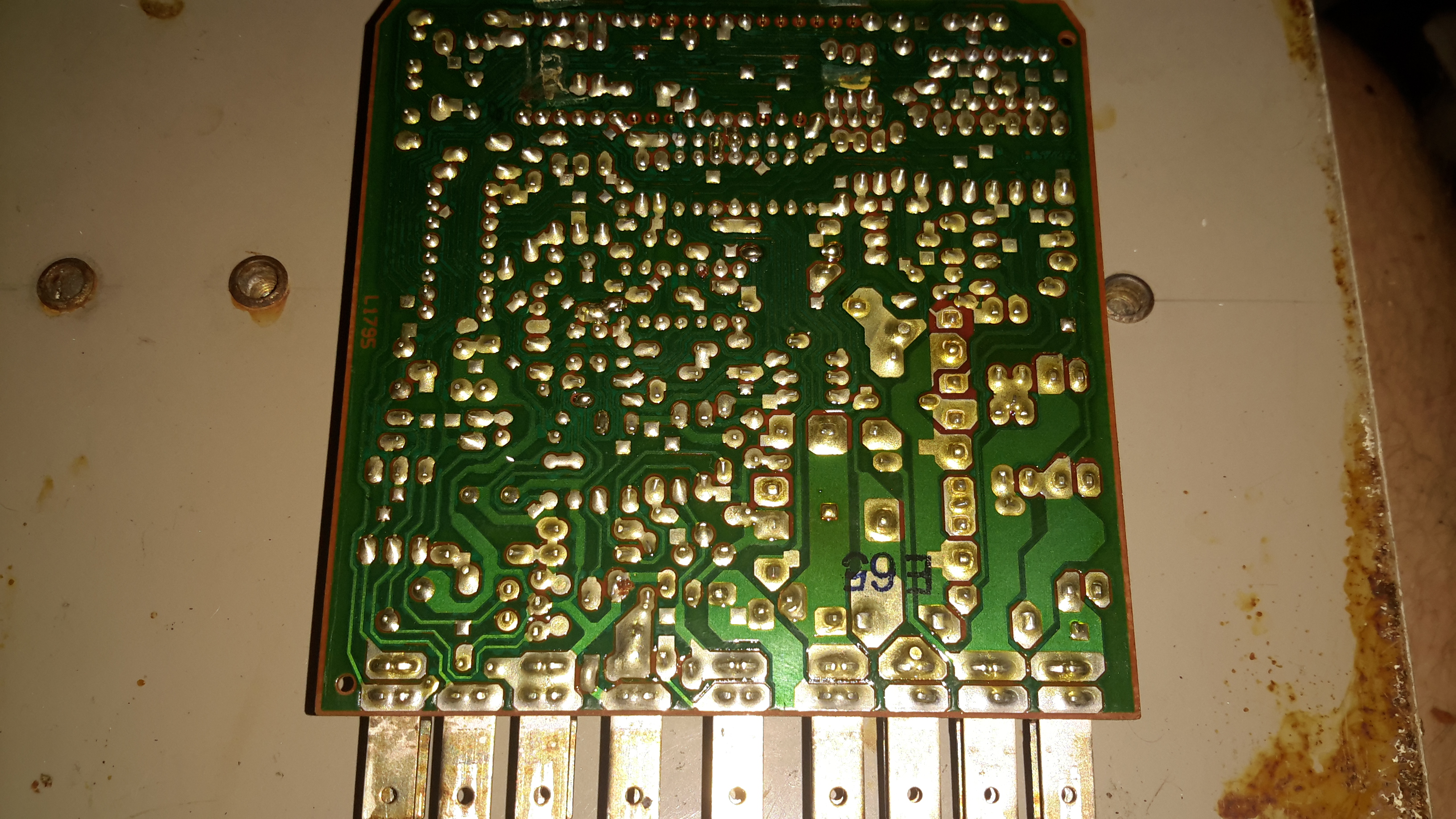
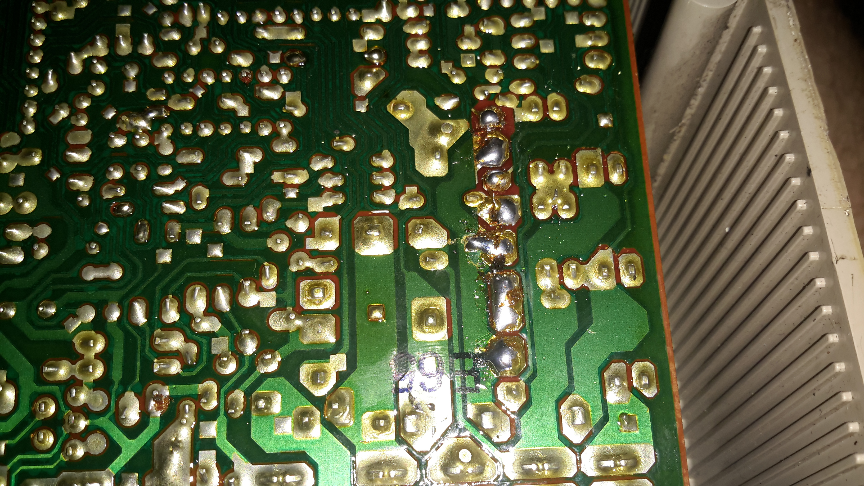
ECU PCB Solder Side
Here’s the solder side of the PCB, which has a generous coating of sealant to keep moisture out.
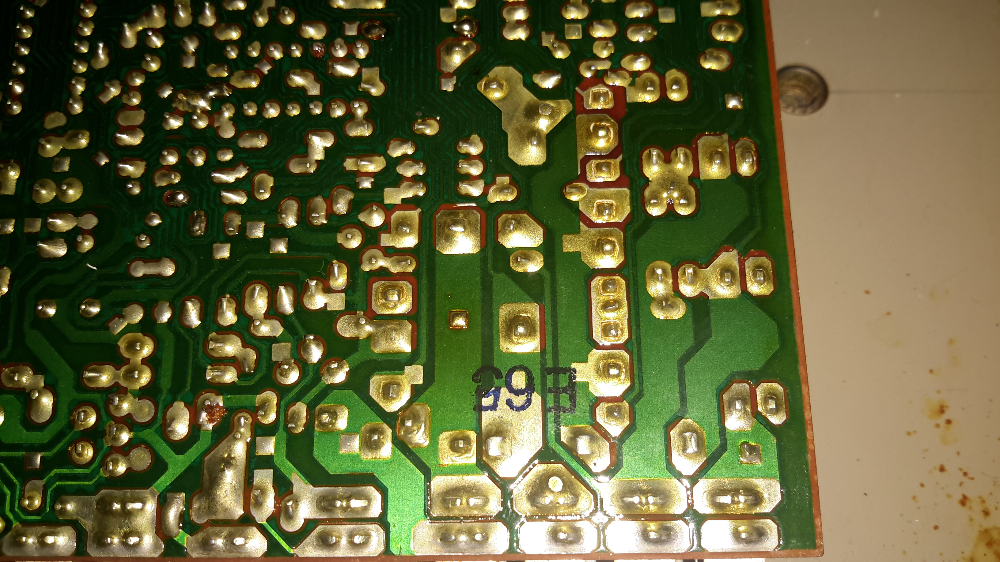
Bad Joint Closeup
Looking at the solder joints for the row of relays on the top side of the PCB, it looks like that there’s some dry joints here.
I suspect that years of vibration has taken it’s toll, as the relays are otherwise unsupported. It wouldn’t be possible to use silicone to secure these devices as they are completely open – any sealant would likely stop them from operating.
Resoldered Joints
Using a very hot soldering iron I managed to get the joints to reflow properly, using lots of flux to make sure the conformal coating didn’t interfere with the reflow.
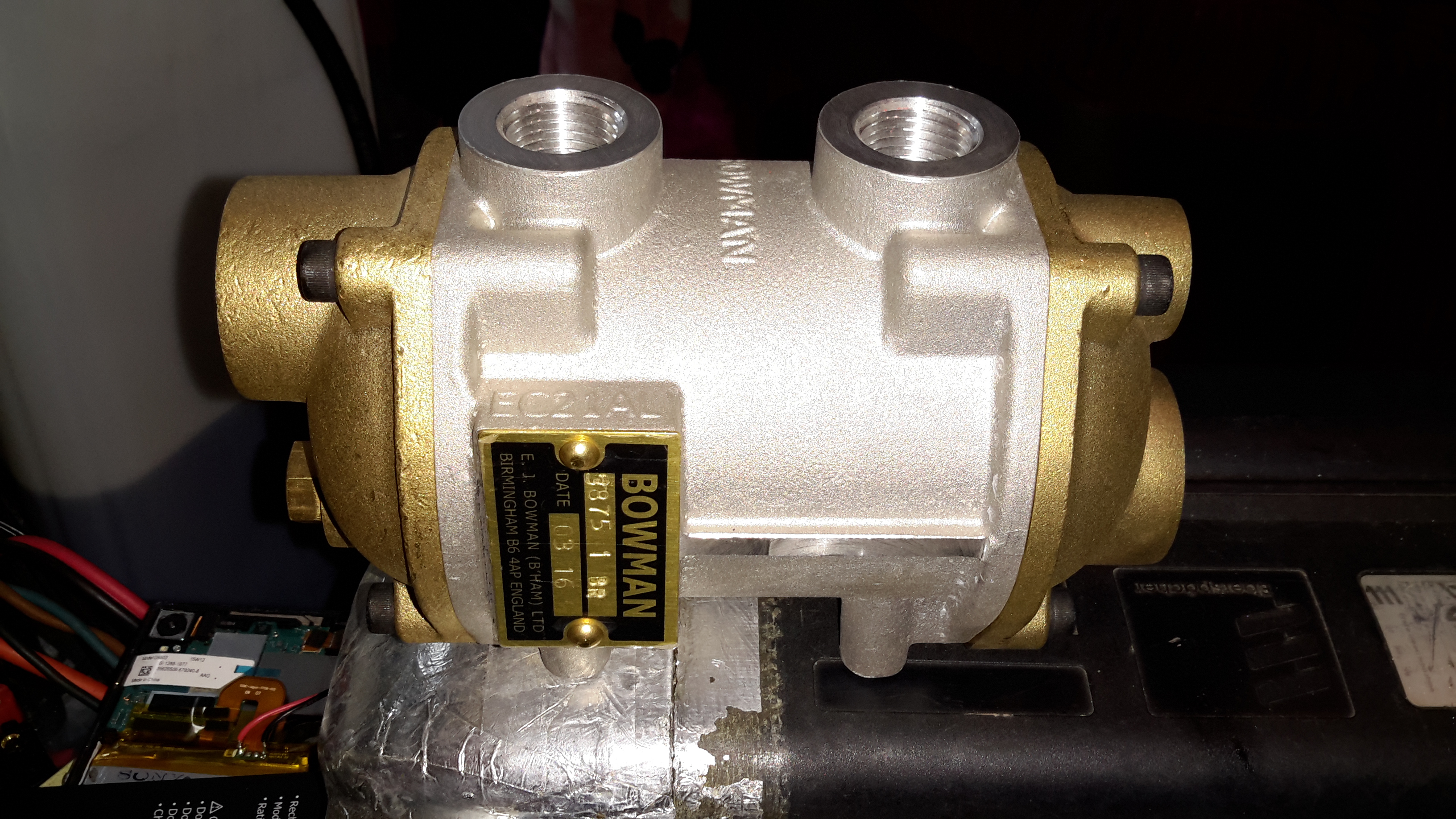
To solve some engine oil overheating problems on board nb Tanya Louise, we decided to replace the air-over-oil cooler, with an water-over-oil cooler, with separate cooling drawn straight from the canal, as the skin tanks are already overloaded with having to cope with not only cooling the engine coolant, but also the hydraulic system oil as well.
These units aren’t cheap in the slightest, but the construction quality & engineering is fantastic.
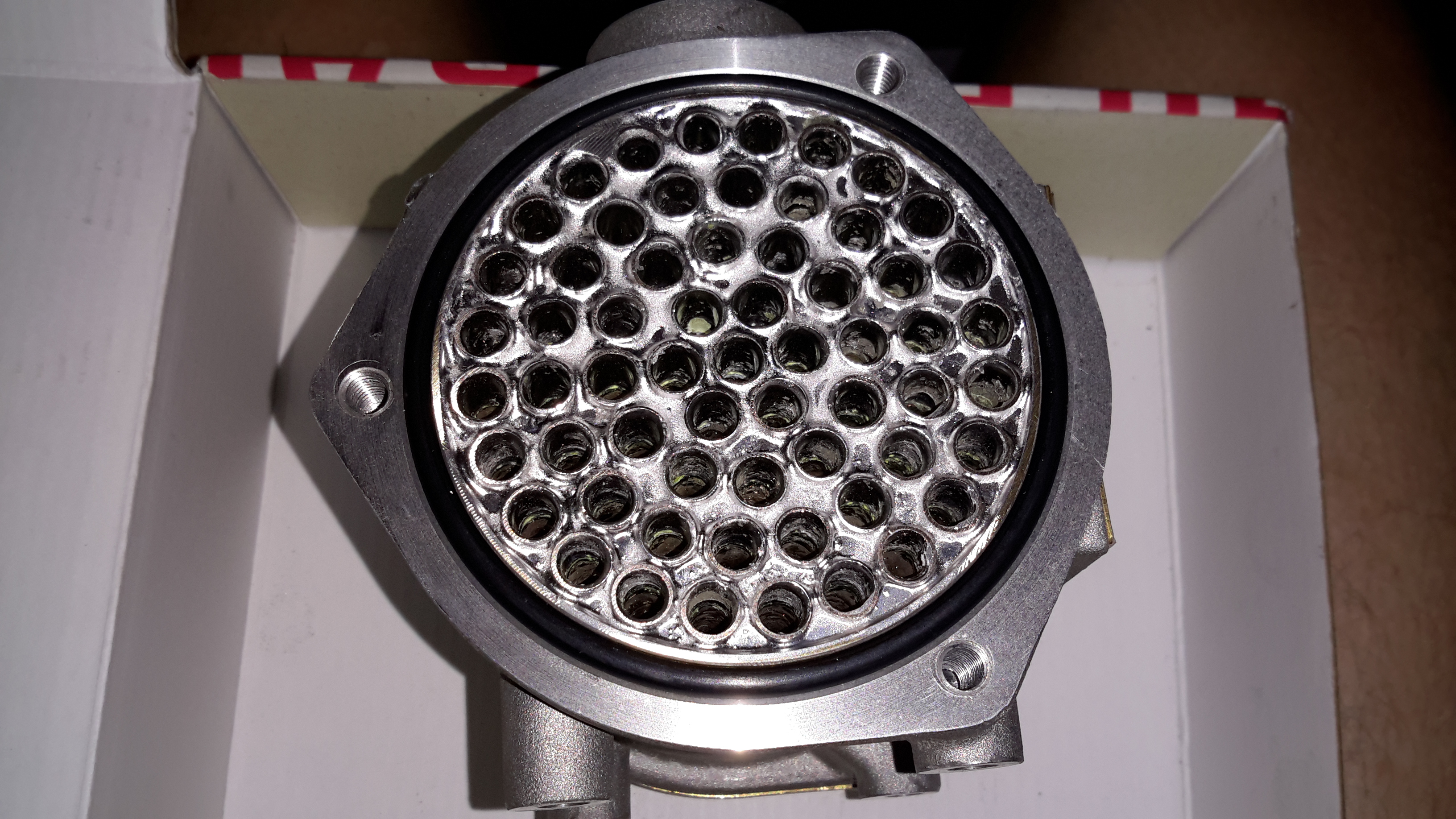
Tube End Plate
Unbolting the end cover reveals the brass tube end plate, soldered to all the core tubes in the cooler. An O-Ring at each end seals both the end cover & the interface between the tube plate & the outer casing.
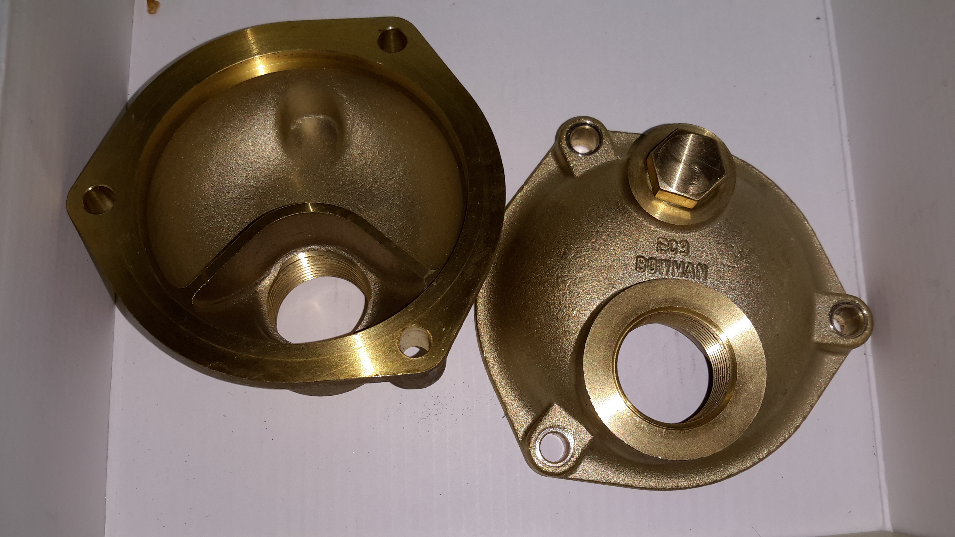
End Caps
The end caps have baffles cast in to direct the cooling water in a serpentine path, so the oil gets the best chance at dissipating it’s heat to the water.
Tube Stack
The oil side of the system is on the outside of the tubes, again baffles placed along the stack direct the oil over the highest surface area possible.
Outer Shell
The outer shell is just a machined alloy casting, with no internal features.
This is something I’ve never seen before. Yesterday, on the Lower Peak Forest Canal, a bunch of kids on off-road bikes came thundering down the towpath – one even pulled a wheelie.
There’s considerable motion blur in the photos, as they were doing some speed, at least 30MPH at that stage.
I did get significant verbal abuse of them for having a camera on them, but thee didn’t bother stopping. This happened at the Romiley side of Woodley Tunnel, just past the portal.
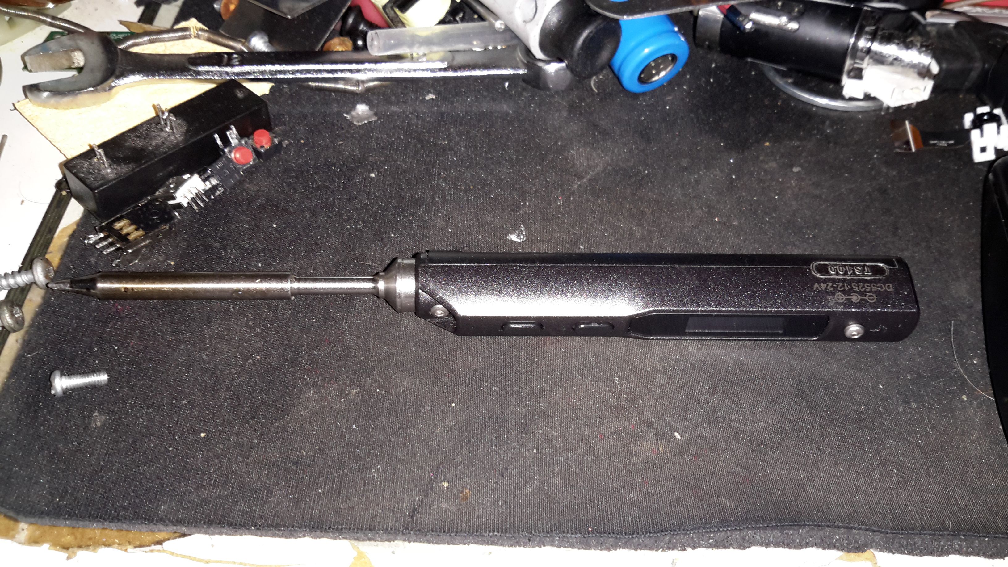
When I ordered the tiny USB soldering iron, I decided a proper iron upgrade would be a good idea. Looking around for something that didn’t require AC mains power turned up the TS100, a Chinese design, that unusually is actually very good! Above is the handle itself, with it’s small OLED display & two operation buttons.
This iron is controlled by a STM32 ARM microcontroller, the firmware & schematics are completely open-source.
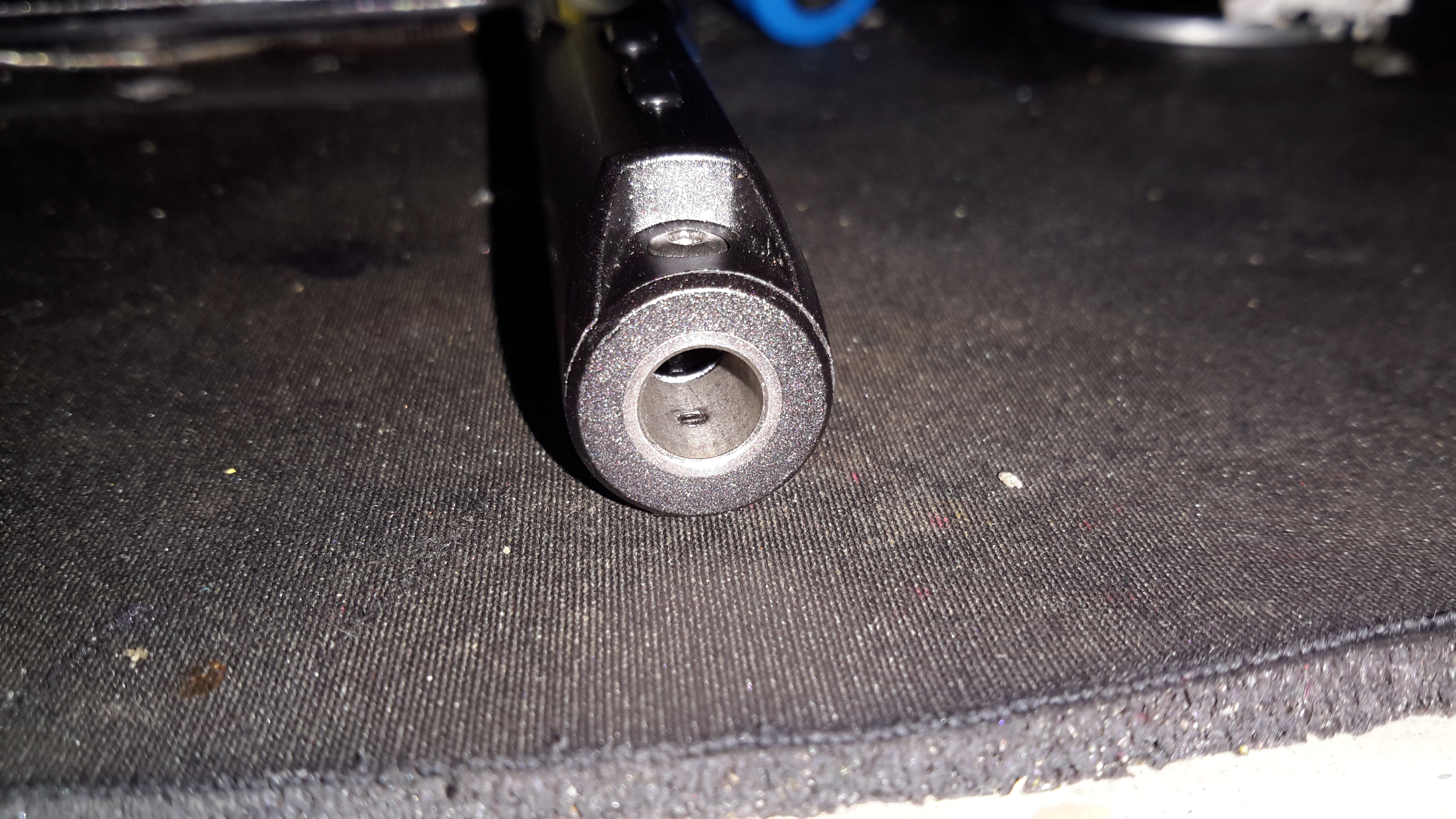
DC Input Jack / USB Port
The bottom end of the iron has the main DC input jack, designed with laptop chargers in mind (DC input range from 10v-24v). Above that is the micro USB port for programming.
Heating Element Socket
The iron tips slot into the other end, many different tip types & shapes are available. The one supplied was the simple conical tip.
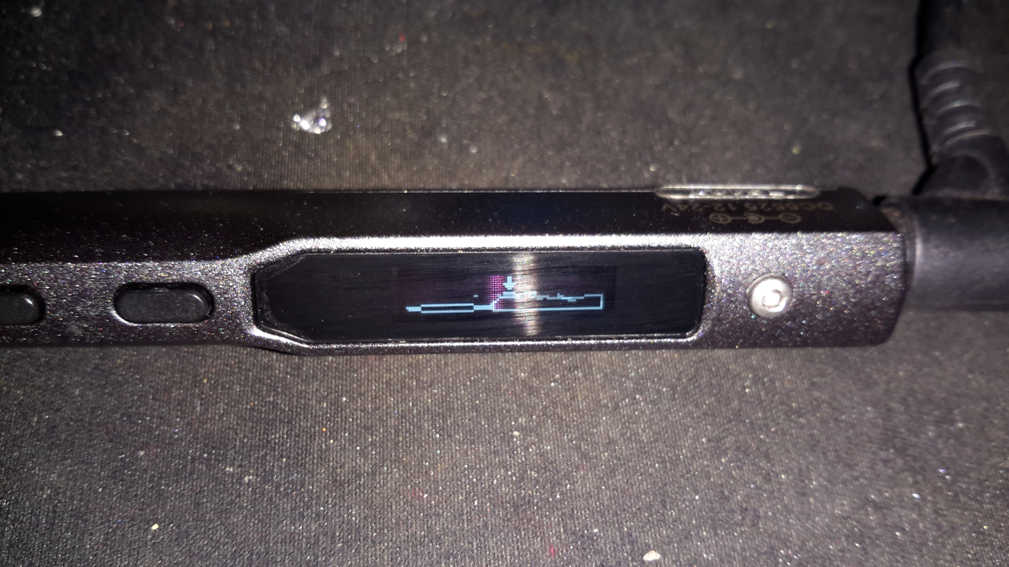
Standby Screen
Plugging the iron into some power gets a standby screen – it doesn’t just start heating immediately, for safety.
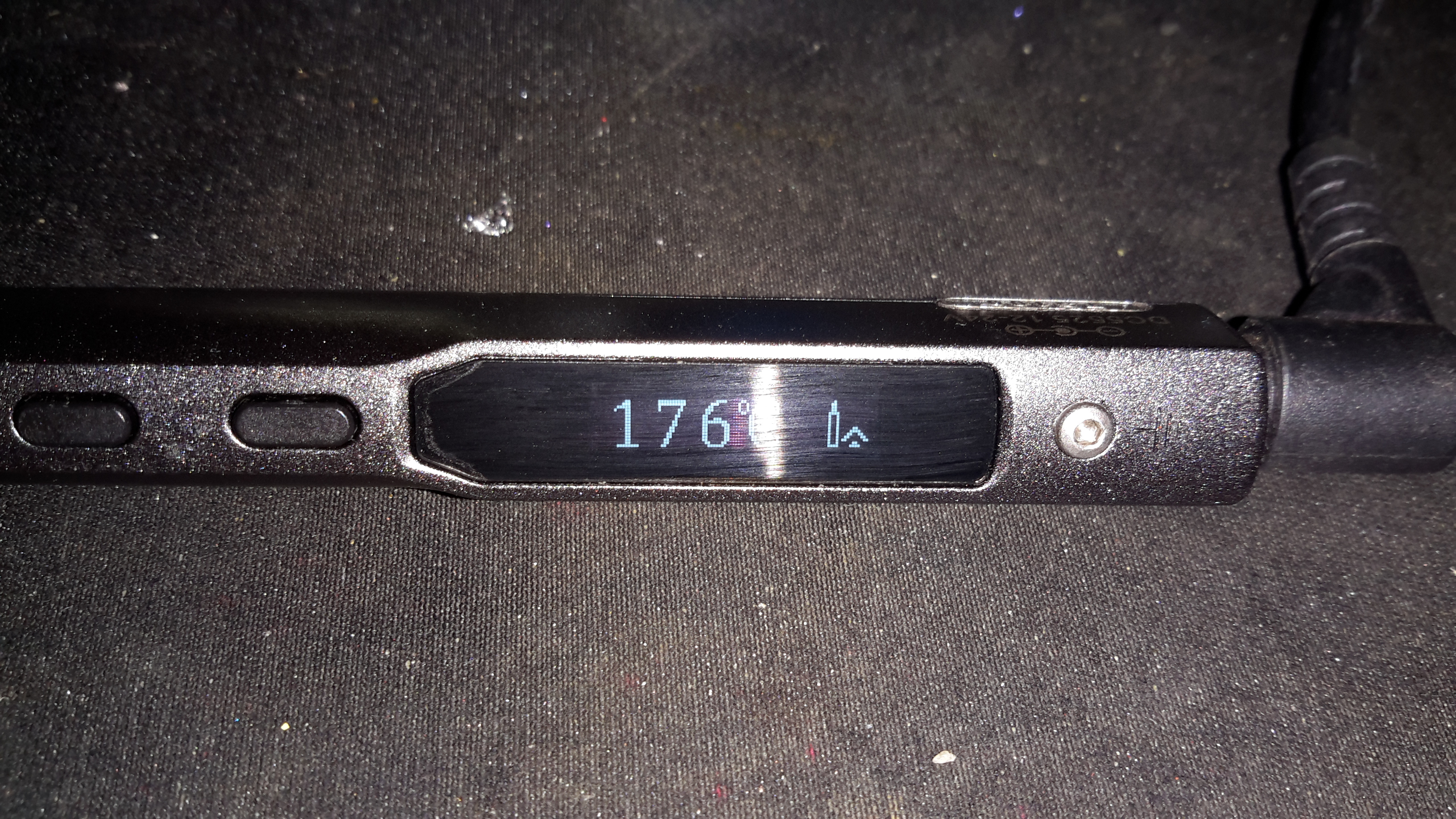
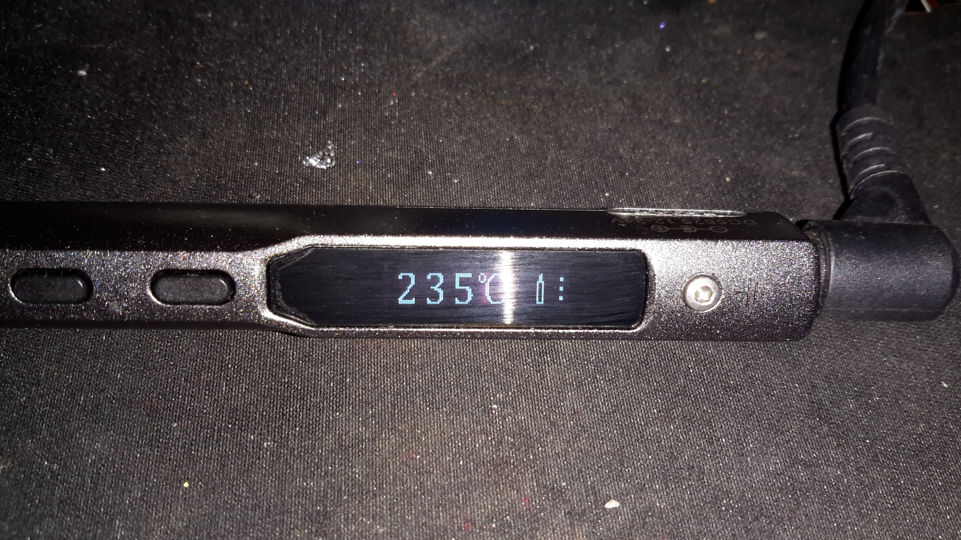
Heating
The left hand button starts the heater, which on a 24v input voltage gets to operating temperature well within 10 seconds.
Temperature Stable
The right hand screen icon changes when the temperature has stabilized. The control PCB has an integrated accelerometer, leaving the iron hot for a few minutes triggers a timeout & it powers down. Once picked up again, the heater instantly restarts.
The operating temperature is adjustable with the pair of buttons, from 100°C to 400°C.
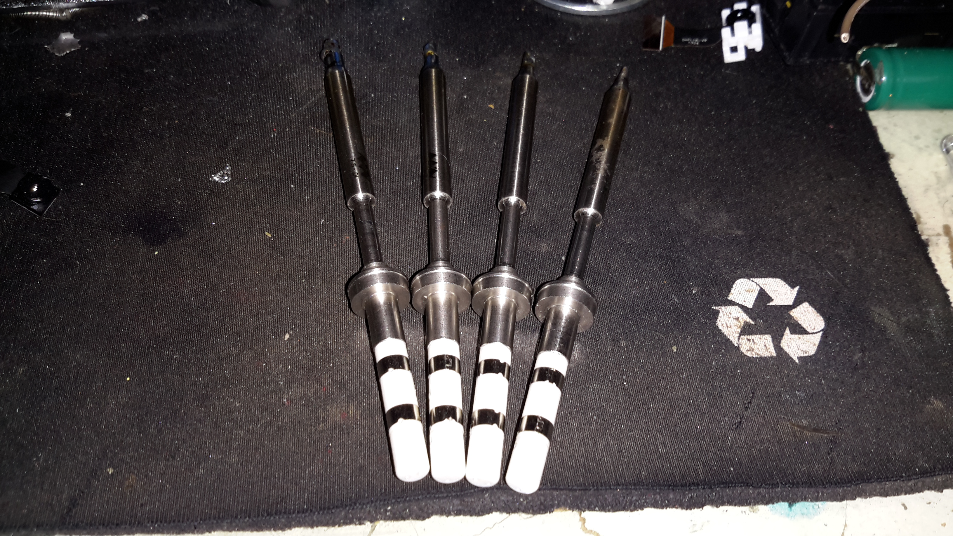
Different Bits
Here’s a selection of bits for the iron. The design is very similar to the Hakko T15 series of irons, but these are a much shorter version. Like the Hakko versions, the actual tips aren’t replaceable, once the bit burns out, the entire assembly is replaced.
TS100 Soldering Iron
Here’s the iron fully assembled. The entire device is about the same length as just the heating element from a Hakko T15!
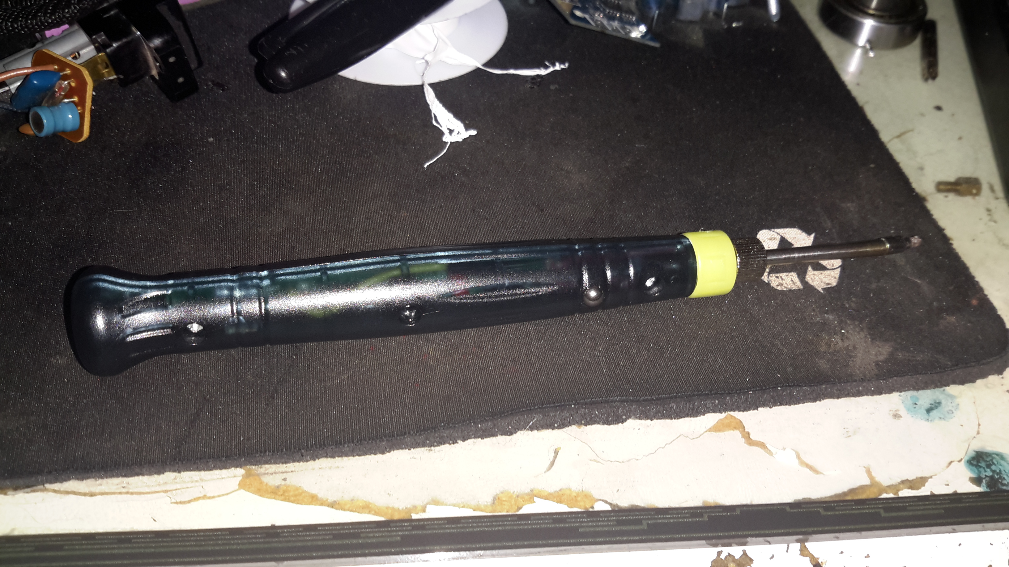
Here’s a novel little gadget, a USB powered soldering iron. The heating tip on these is very small & might be useful for very small SMD work. Bigger joints not so much, as it’s only rated at 8W. (Still breaks the USB standard of 2.5W from a single port).
These irons aren’t actually too bad to use, as long as the limitations in power are respected. Since nearly everything has a USB power port these days, it could make for a handy emergency soldering iron.
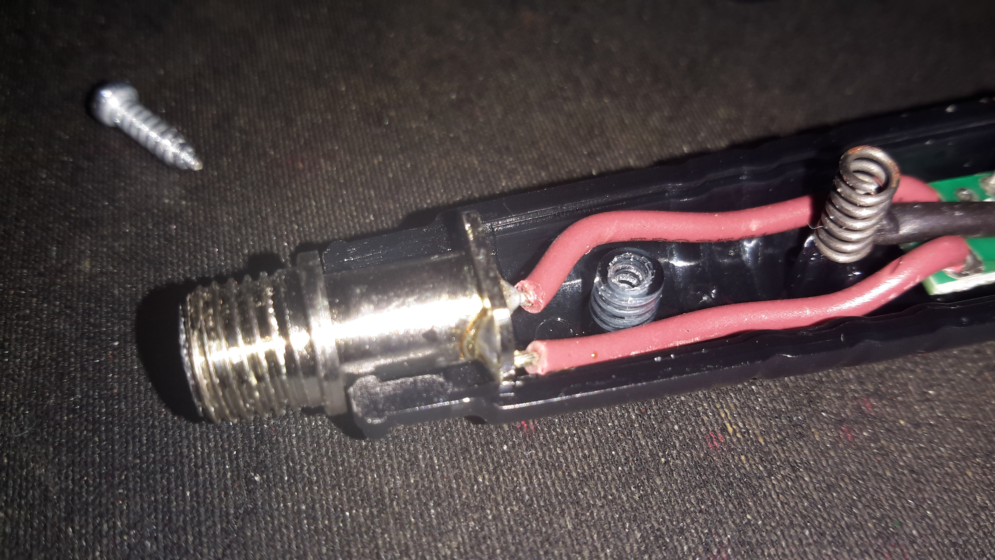
Heater Socket
The heater & soldering bit are a single unit, not designed to be replaced separately. (I’ve not managed to find replacement elements, but at £3 for the entire iron, it would be pretty pointless).
Above is the socket where the heater plugs in, safely isolating the plastic body from any stray heat.
DC Input Jack
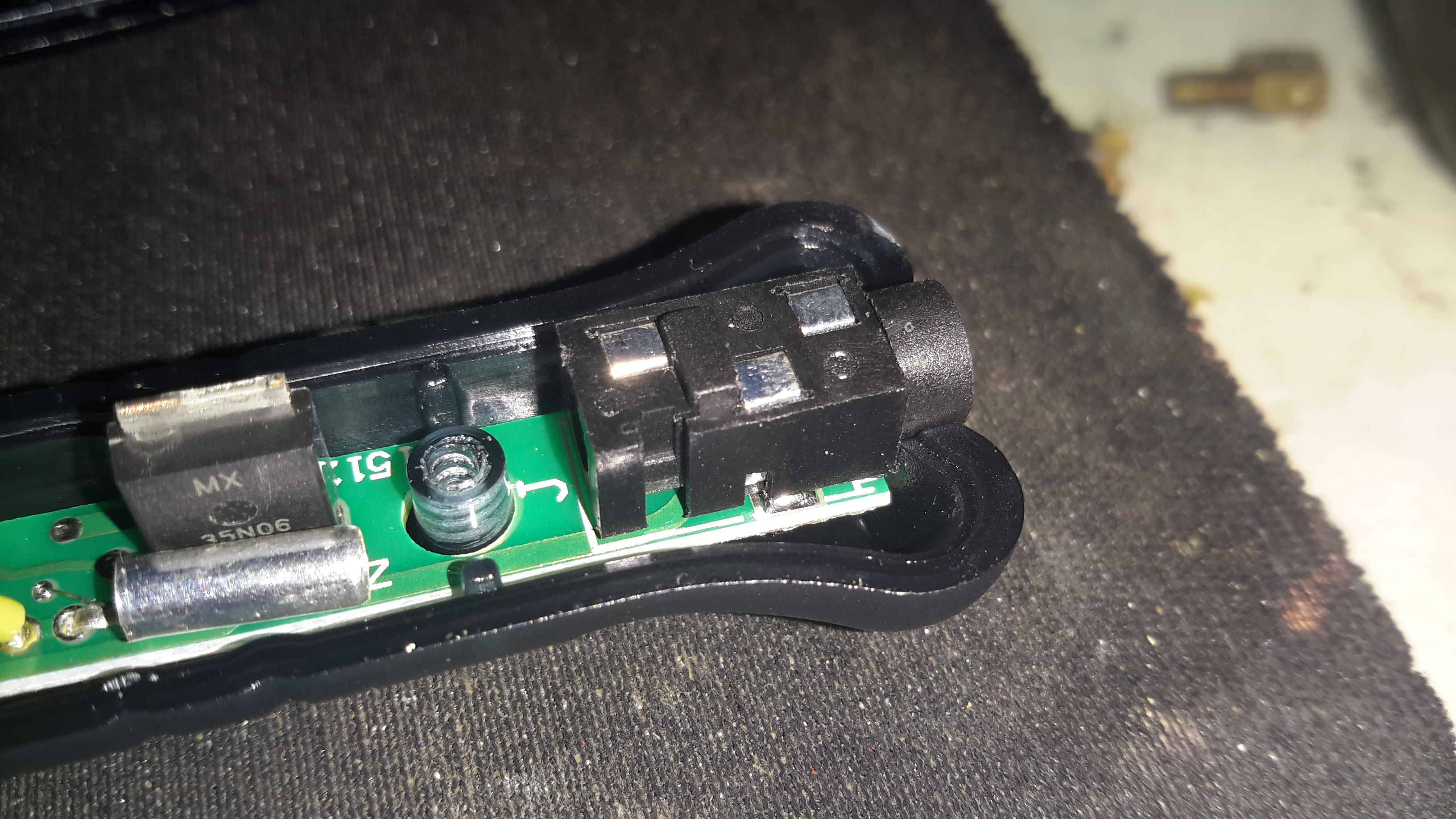
The DC input is a 3.5mm audio jack, a non-standard USB to 3.5mm jack cable is supplied. Such non-standard cables have the potential to damage equipment that isn’t expecting to see 5v on an audio input if it’s used incorrectly.
Touch Sensor & LED
There isn’t actually a switch on this unit for power management, but a clever arrangement of a touch button & vibration switch. The vertical spring in the photo above makes contact with a steel ball bearing pressed into the plastic housing, forming the touch contact.
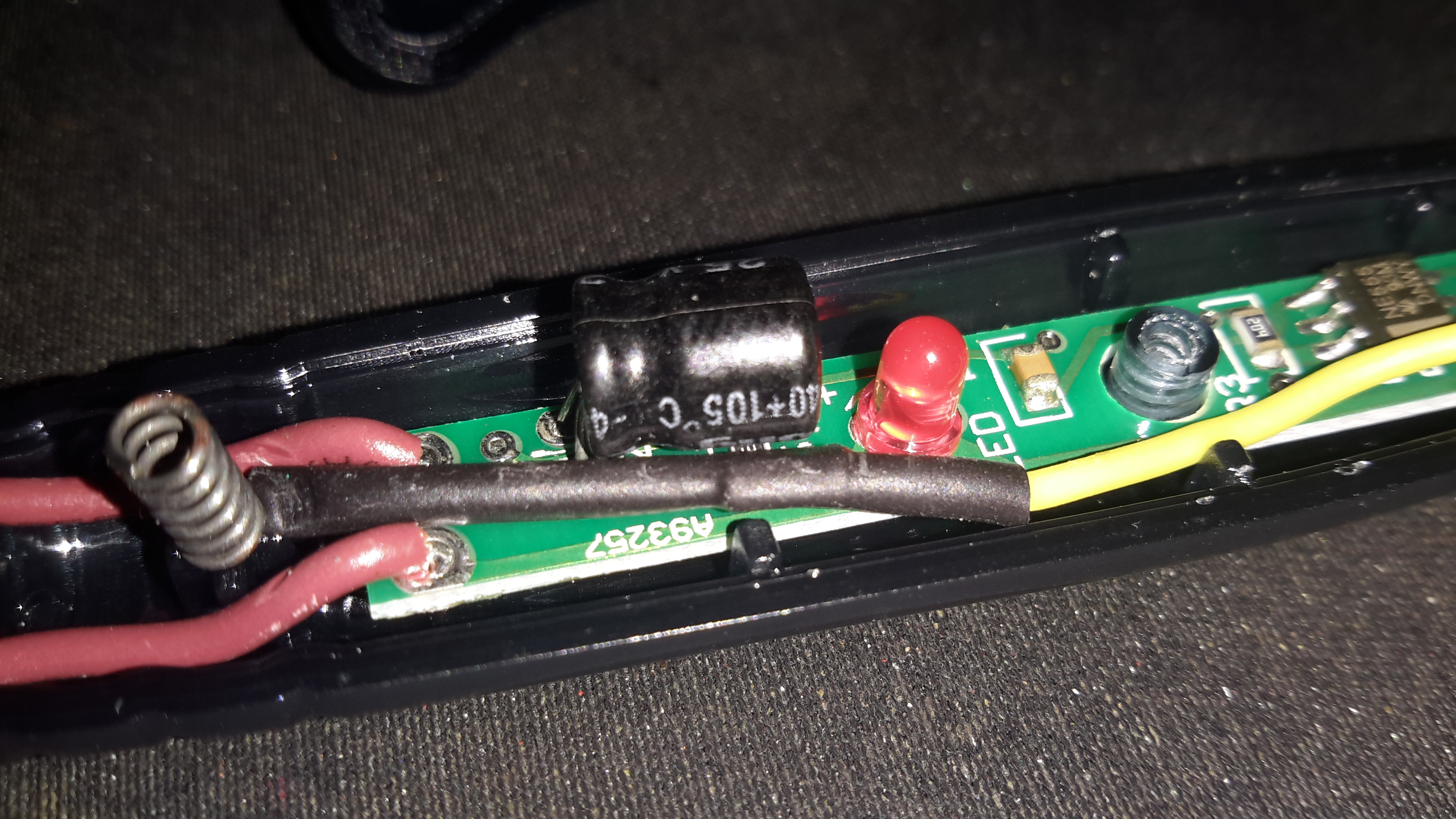
MOSFET
The large MOSFET here is switching the main heater current, the silver cylinder in front is the vibration switch, connected in parallel with the touch button.
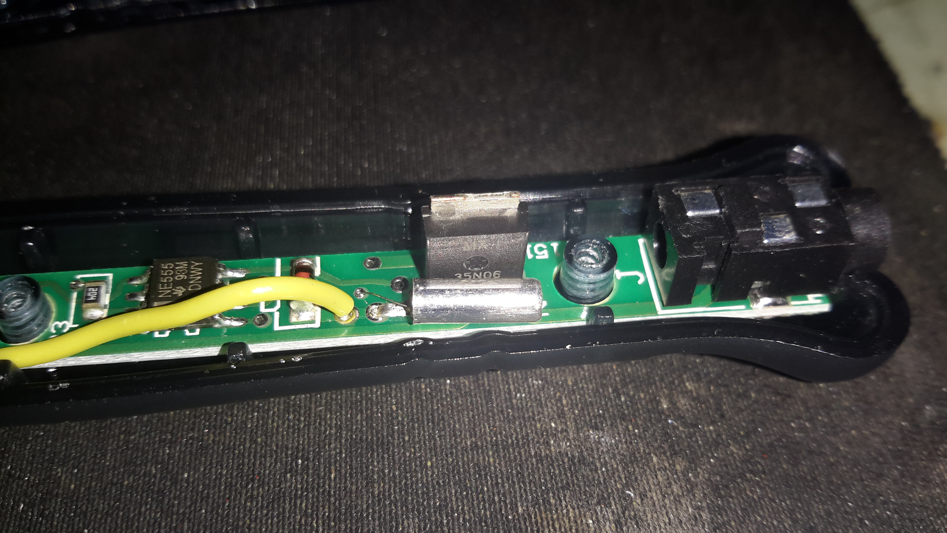
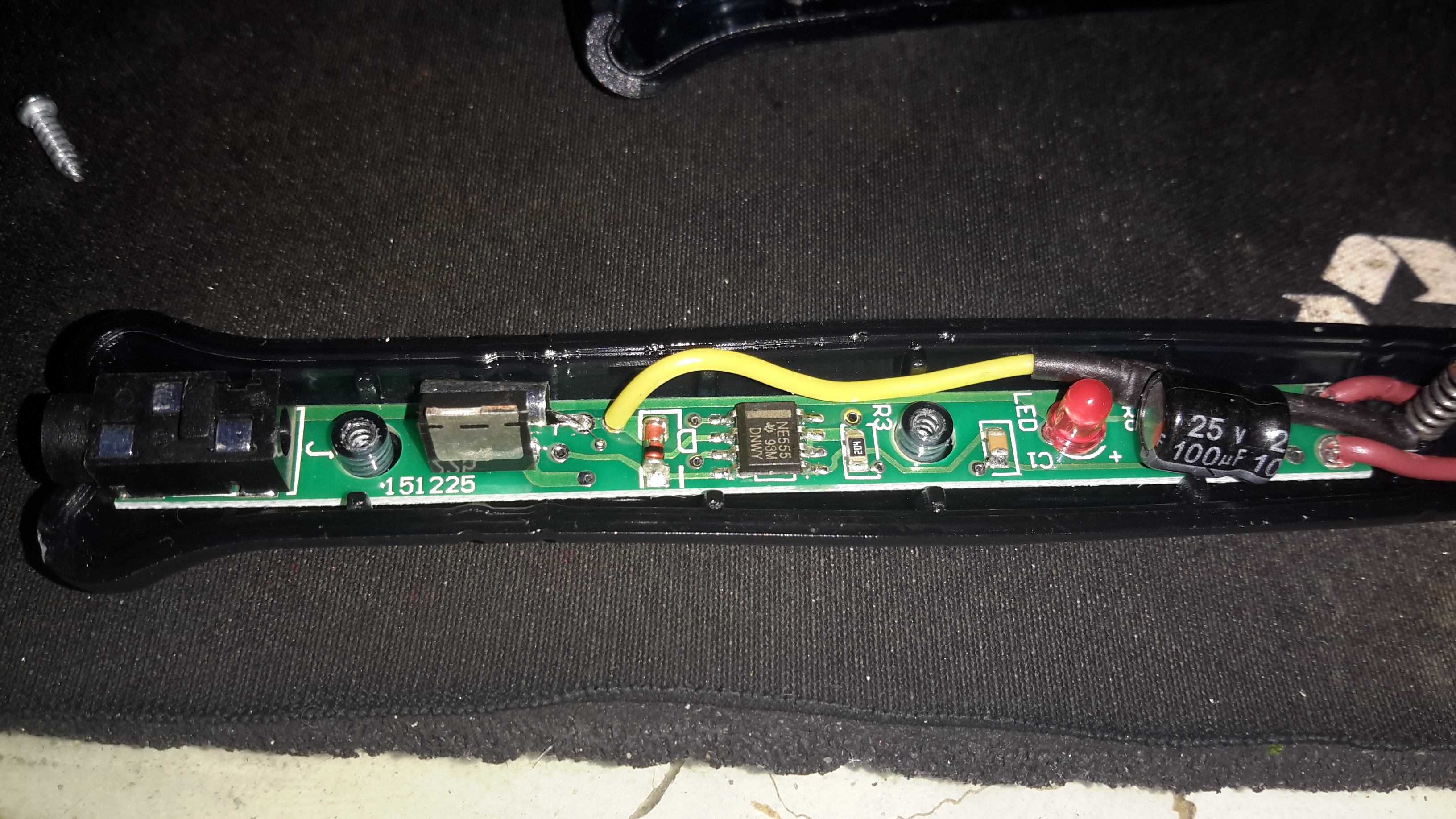
PCB
The main controller is very simple. It’s a 555 timer configured in monostable mode. Below is a schematic showing the basic circuit.
555 Monostable
Big Clive also did a teardown & review of this iron. Head over to YouTube to watch.
This website, in various forms, has been around now for about 10 years. Over that time the scope of what I’ve been doing has definitely widened in a big manner.
Considering this, I no longer feel the current website name of “Inside Electronics” is very appropriate, so over the next few weeks, I’ll be re-jigging everything with a new domain name & title:
Experimental Engineering.
The site name is already changed, moving my entire WordPress install over to a new domain will be a bit more labour intensive, with all the internal site links & SEO, so this will be introduced slowly.
(It’s amazing how much this site has evolved over the years, hopefully this evolution will continue!)
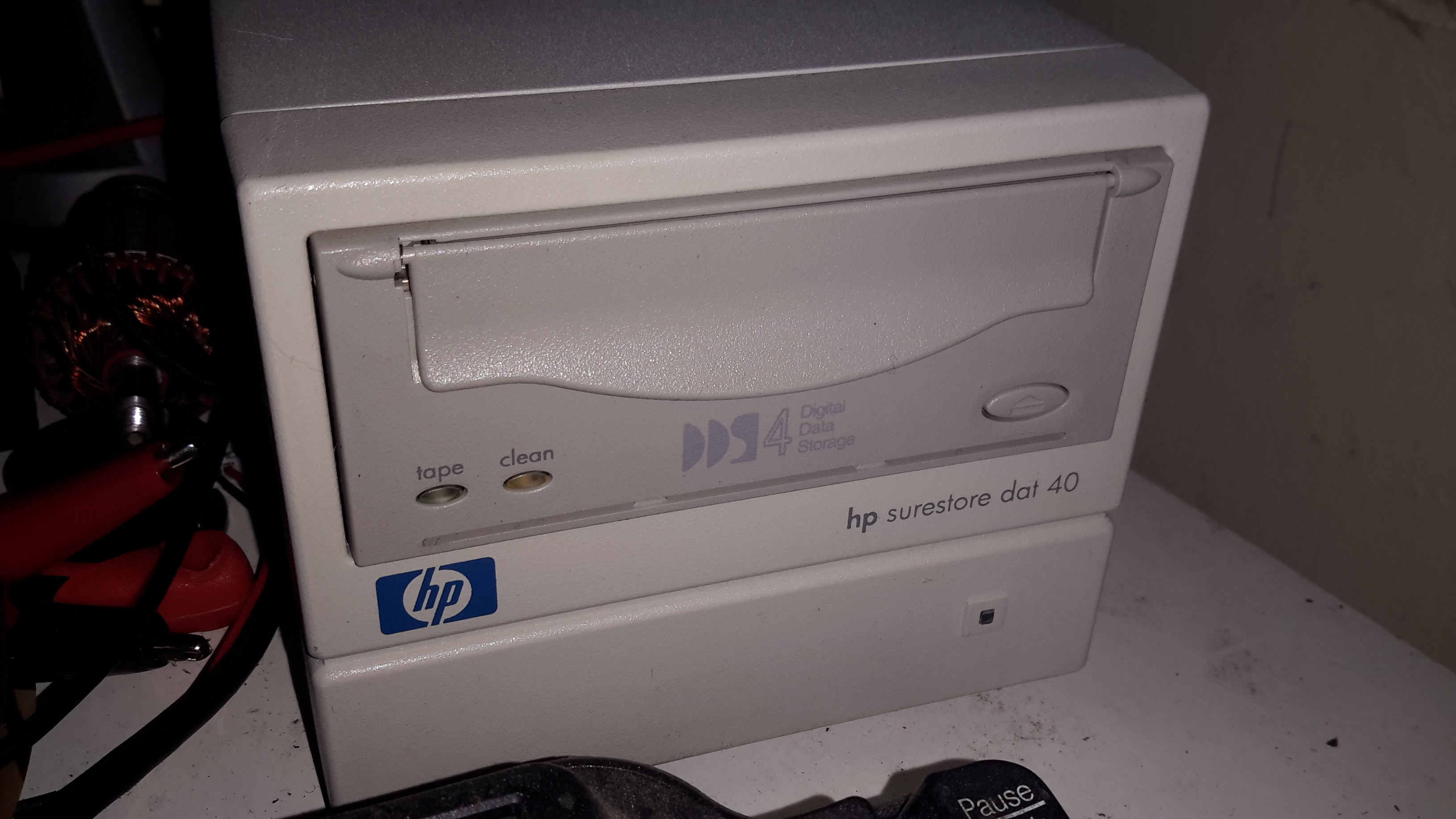
Magnetic tape is the medium of choice for my offline backups & archives, as it’s got an amazing level of durability when in storage. (LTO Has a 30 year archival rating).
For the smaller stuff, like backing up the web server this very site runs on, another format seemed to suit better. Above is a HP DDS4 tape drive, which will store up to 40GB on a cassette compressed.
I picked this format since I already had some tapes, so it made sense.
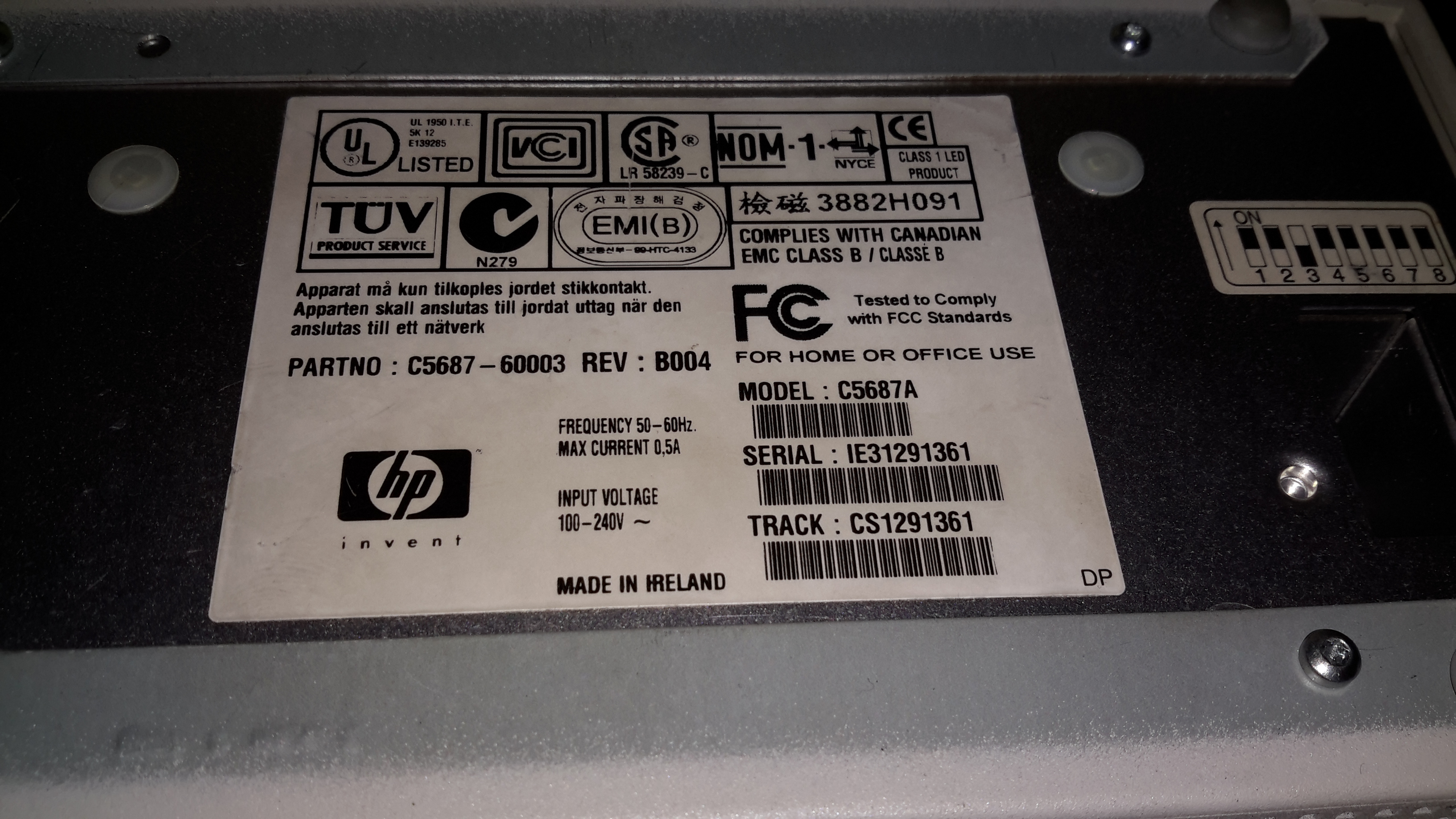
Data Plate
Here’s the info for those who want to know. It’s an older generation drive, mainly since the current generation of tape backup drives are hideously expensive, while the older ones are cheap & plentiful. Unfortunately the older generation of drives are all parallel SCSI, which can be a expensive & awkward to set up. Luckily I already have other parallel SCSI devices, so the support infrastructure for this drive was already in place.
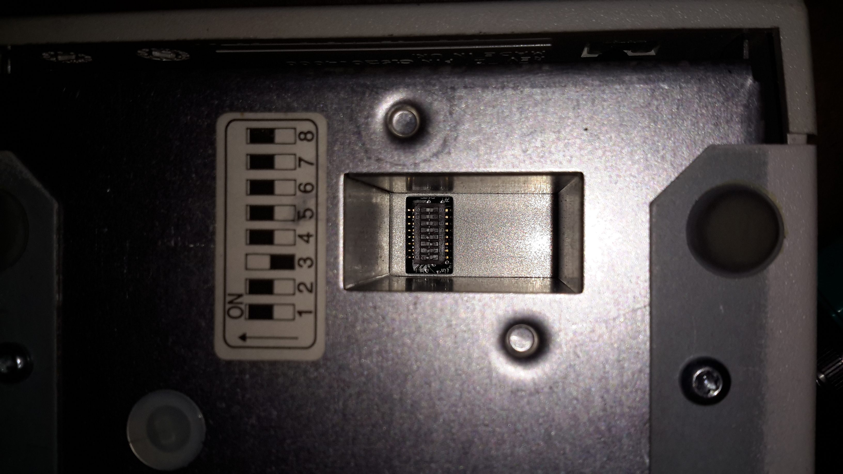
Option Switches
On the bottom of the drive is a bank of DIP switches, according to the manual these are for setting the drive for various flavours of UNIX operating systems. However it doesn’t go into what they actually change.
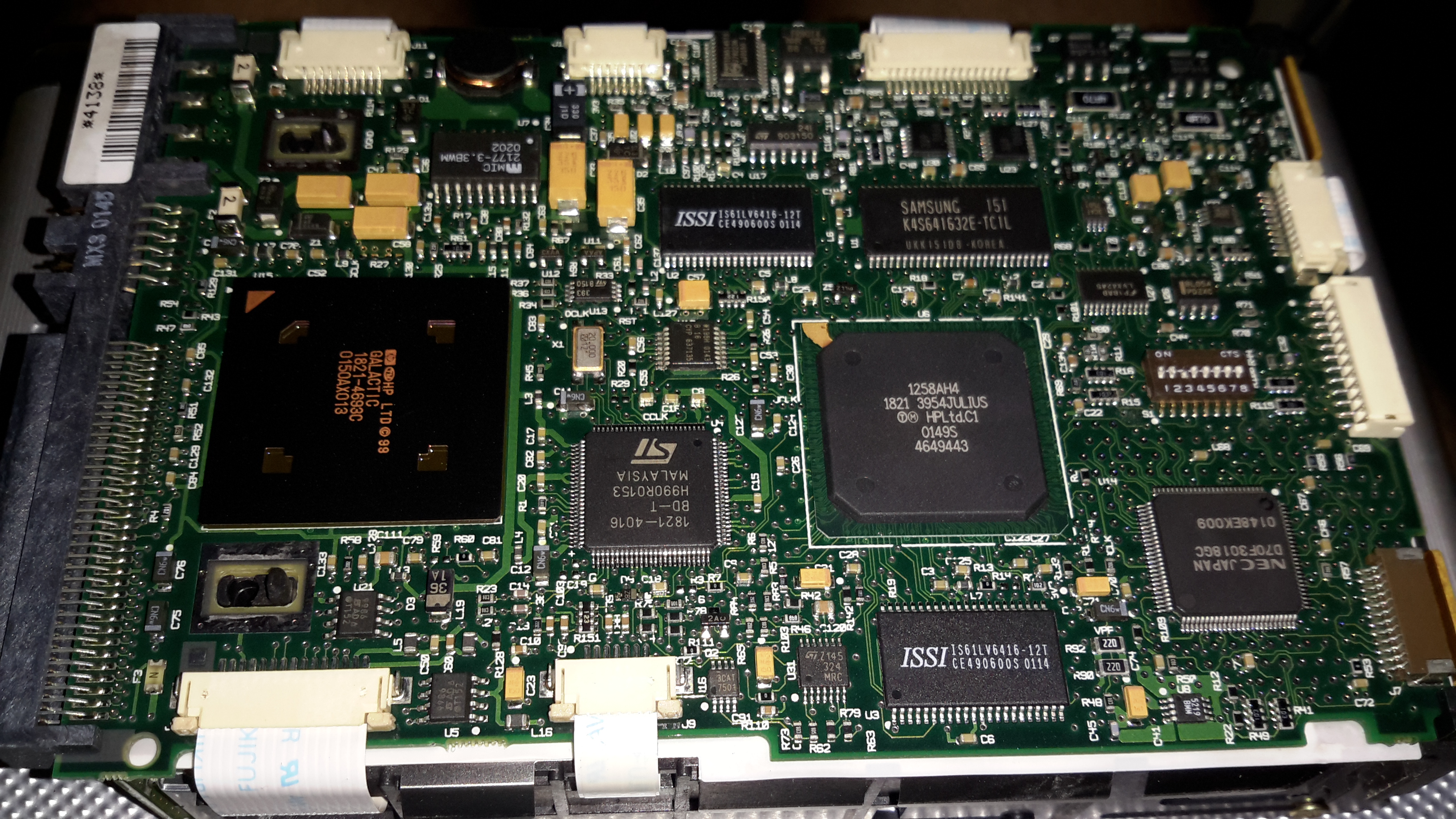
Controller PCB
The bottom of the drive has the control PCB. The large IC on the left is the SCSI interface, I’ve seen this exact same chip on other SCSI tape drives. Centre is a SoC, like so many of these, not much information available.
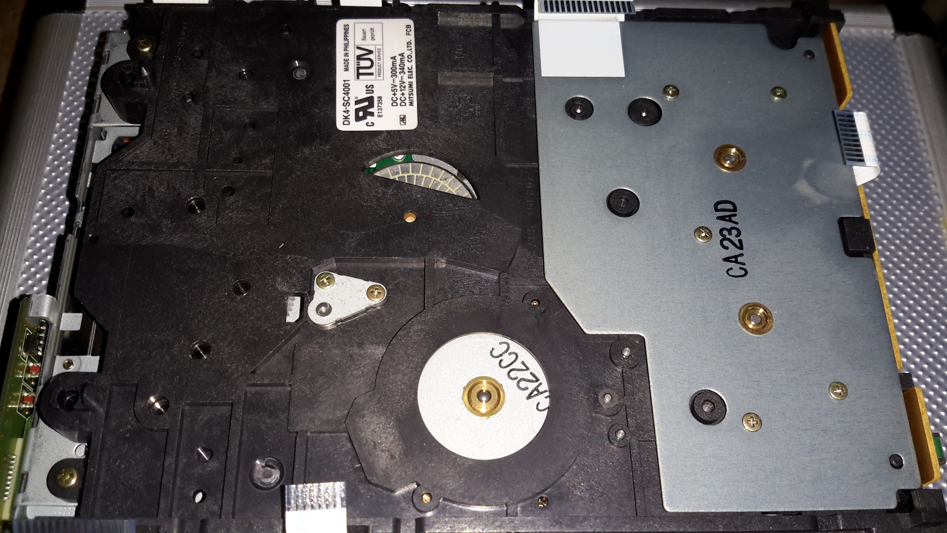
Drive Frame
Removing the board doesn’t reveal much else, just the bottom of the frame with the tape spool motors on the right, capstan motor bottom centre. The bottom of the head drum motor is just peeping through the plastic top centre.
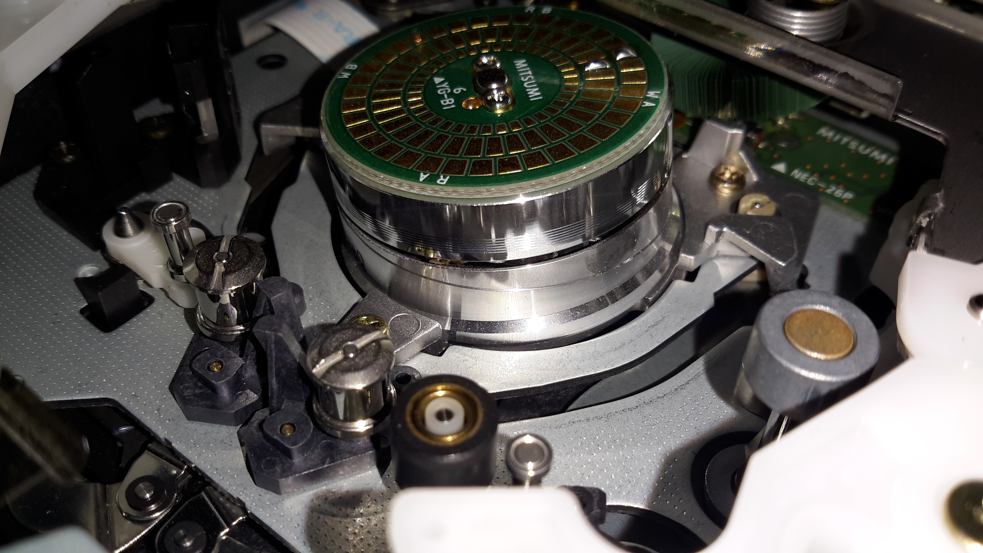
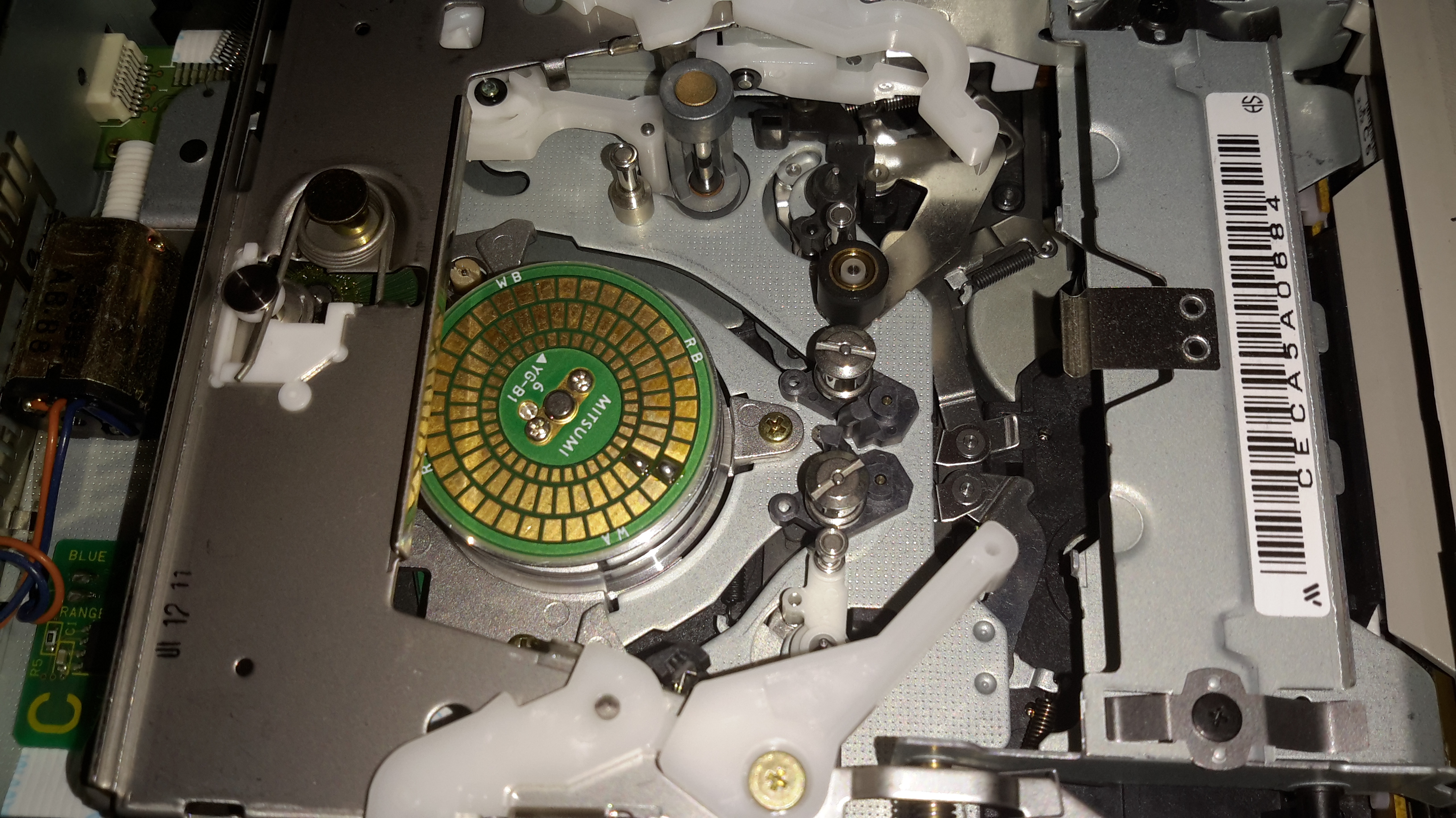
Head Drum
Here’s the head drum itself. These drives use a helical-scan flying head system, like old VHS tape decks. The top of the capstan motor is on the bottom right.
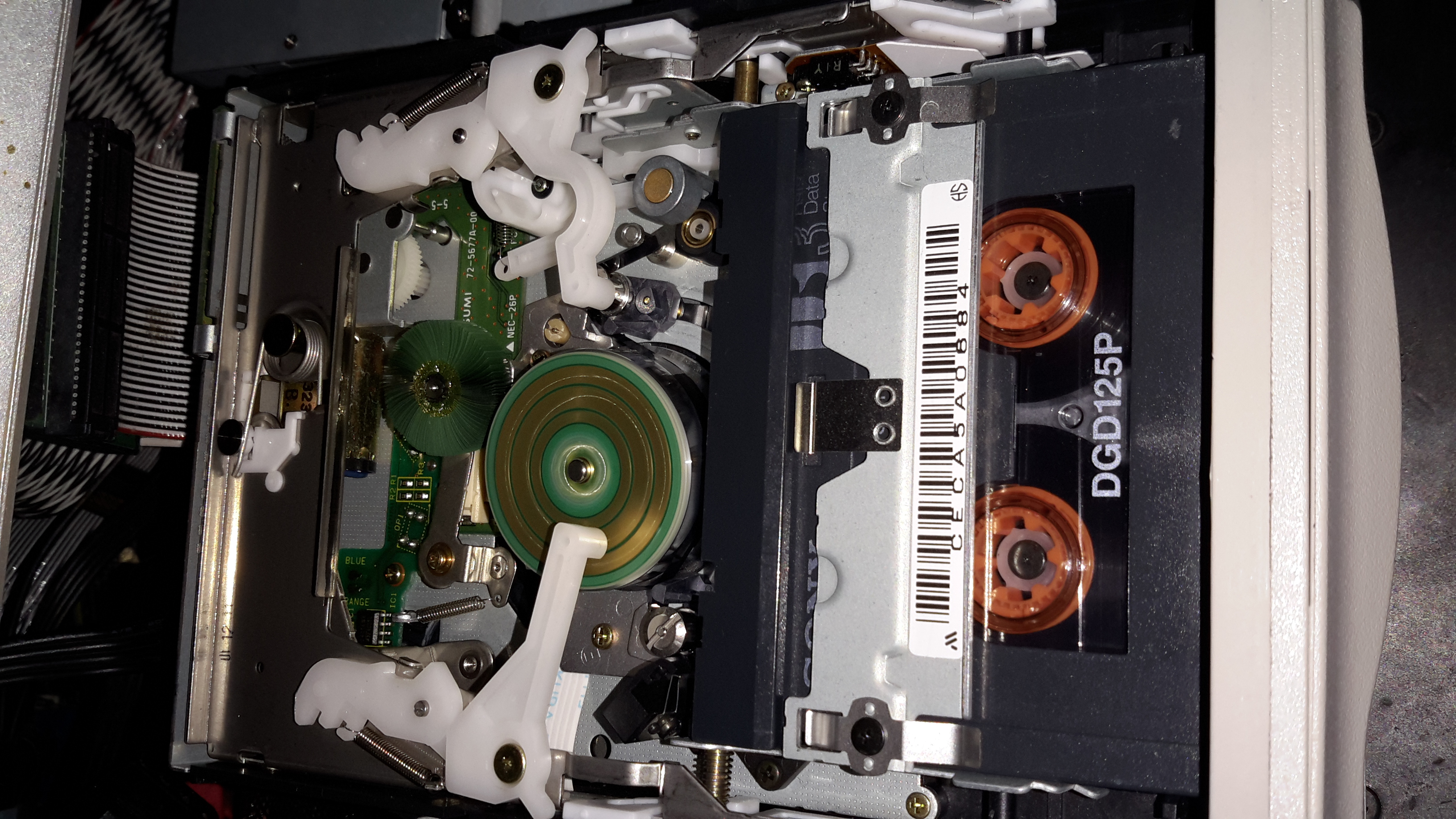
Cleaning Brush
Hidden just under the tape transport frame is the head cleaning brush. I’m not sure exactly what this is made of, but it seems to be plastic.
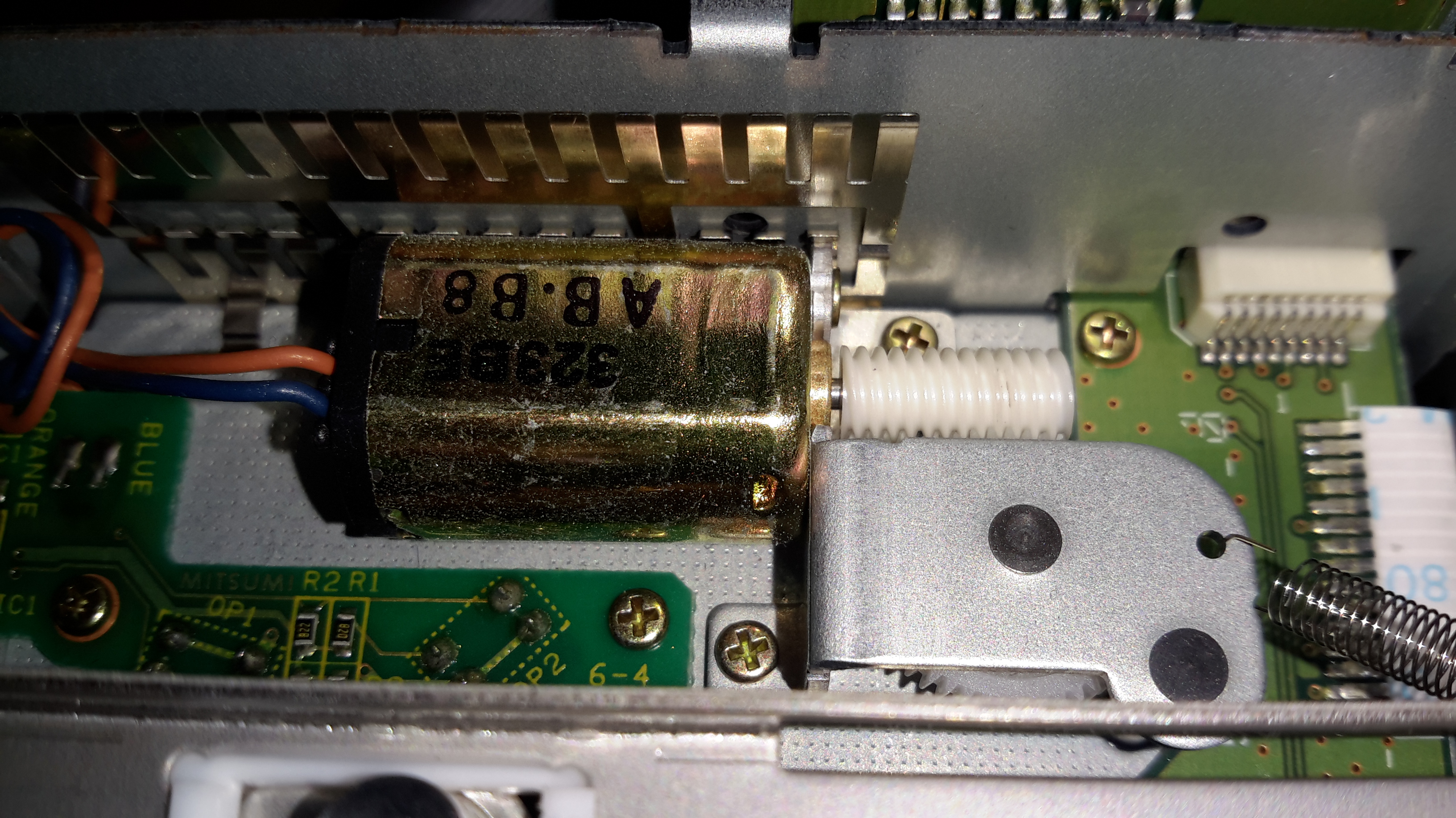
Loading Motor
A single small DC motor with a worm drive handles all tape loading tasks. The PCB to the bottom left of the motor holds several break-beam sensors that tell the drive what position the transport is in.
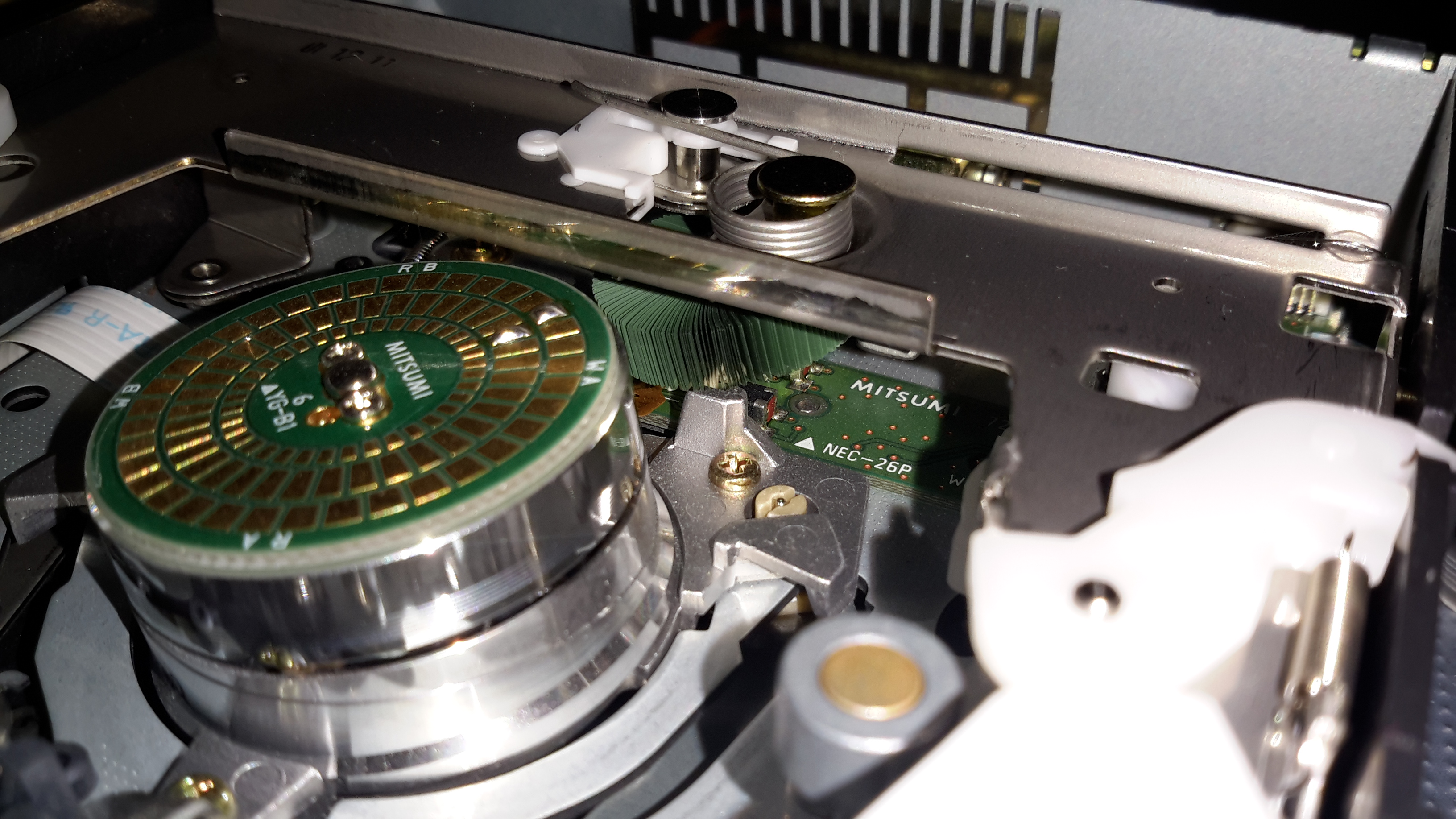
Tape Transport Mech
Here’s the overall tape transport. The PCB on top of the head drum is a novel idea: it’s sole purpose in life is to act as a substrate for solder blobs, used for balancing. As this drum spins at 11,400RPM when a DDS4 tape is in the drive, any slight imbalance would cause destructive vibration.
Tape Transport
Here’s the drive active & writing a tape. (A daily backup of this web server actually). The green head cleaning brush can be better seen here. The drive constantly reads back what it writes to the tape, and if it detects an error, applies this brush momentarily to the drum to clean any shed oxide off the heads. The tape itself is threaded over all the guides, around the drum, then through the capstan & pinch roller.
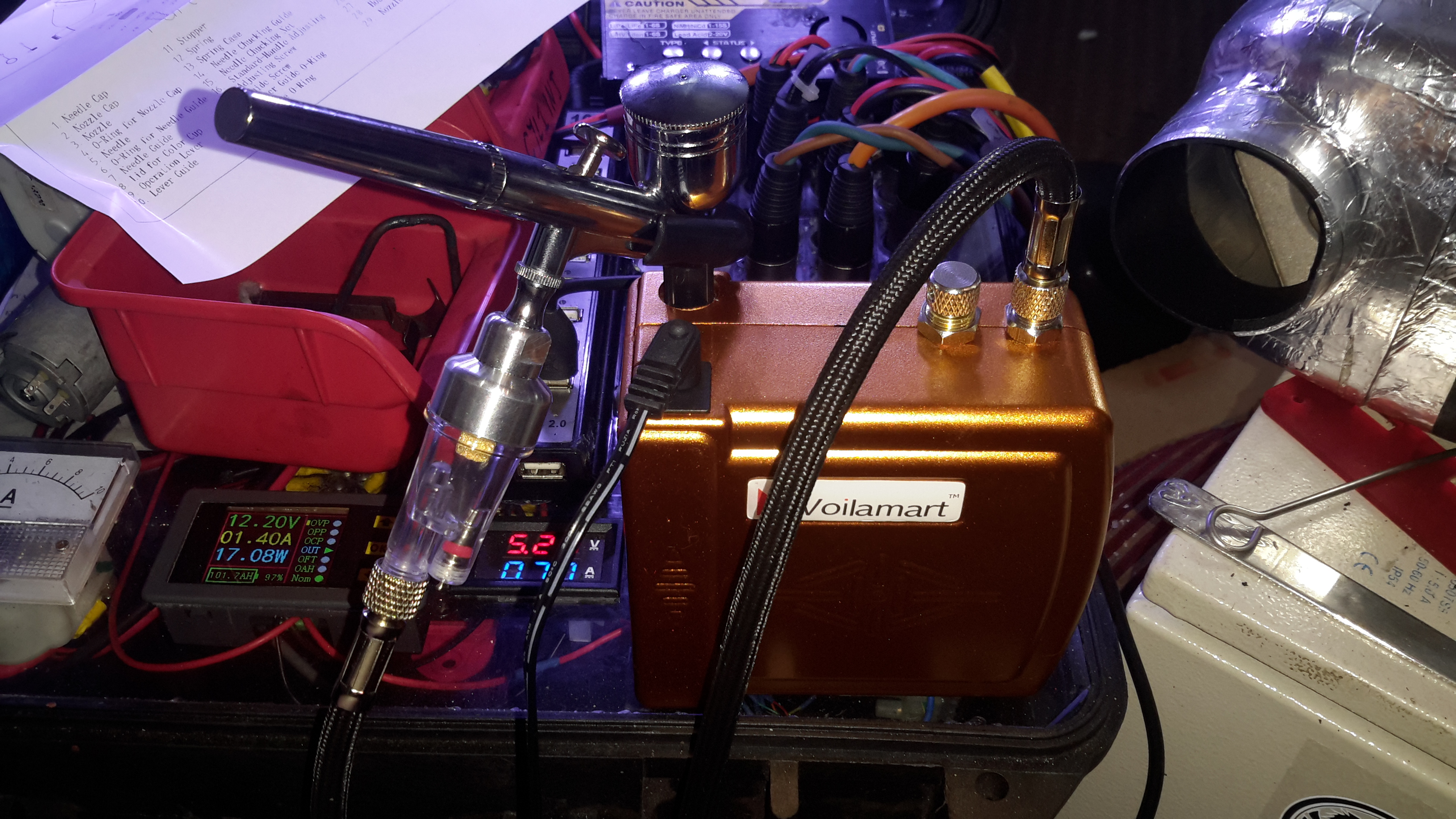
For my latest project, I needed an easier way to paint without messing about with brushes, and the associated marks they leave in a paint job. eBay provided me with a cheap airbrush & compressor.
Airbrush Kit
For less than £30, this kit doens’t look so bad. I’ve never used an airbrush before, but I’ve had no problems with this as yet spraying both water based paints & solvent based paints.
Compressor
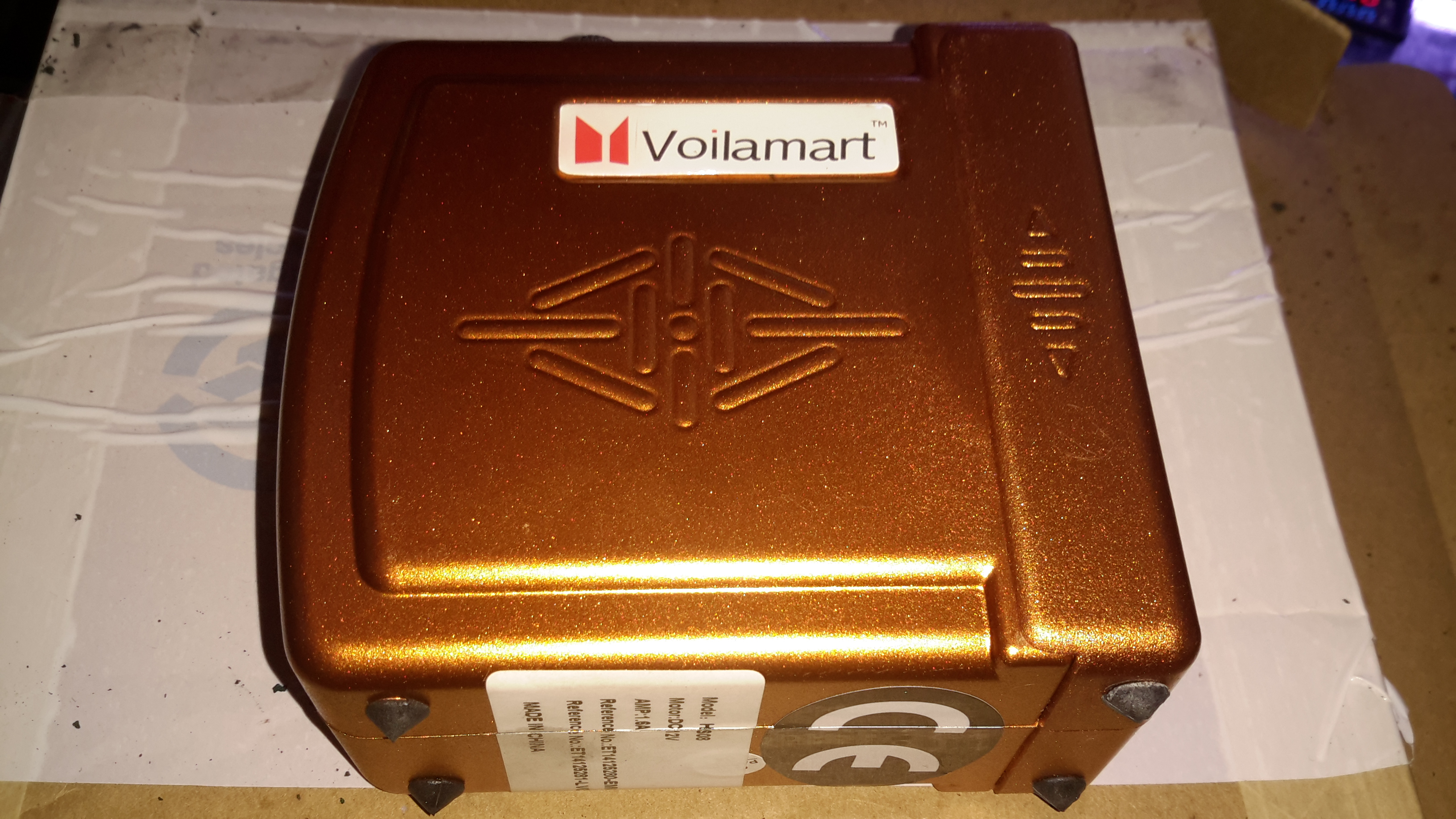
Here’s the compressor itself, this runs on 12v & has an output pressure of 1.5 Bar, which is supposed to be adjustable.
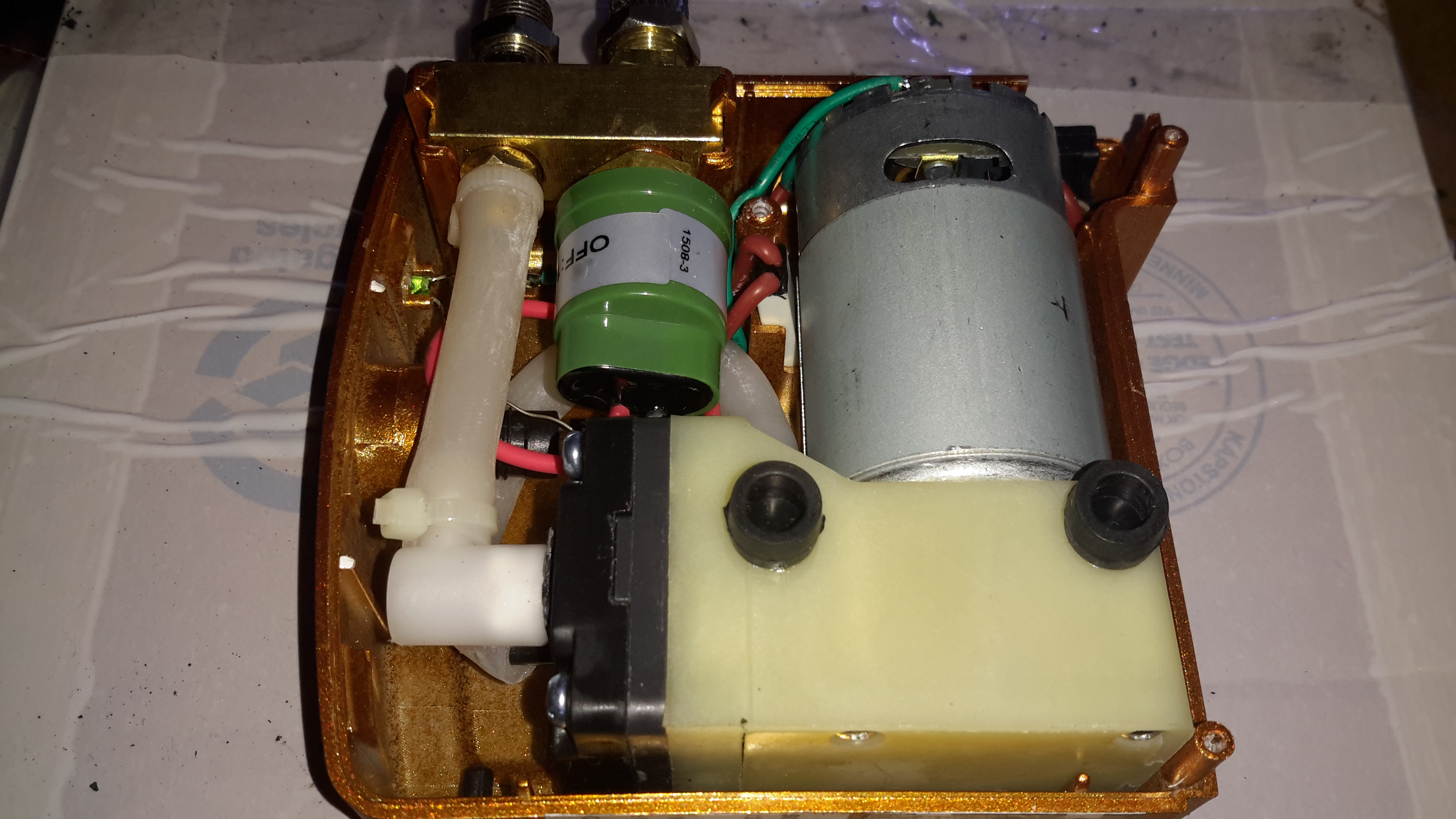
Compressor Internals
Removing a couple of screws reveals the internal components. Nothing much unusual here, a DC diaphragm pump, pressure switch & outlet fittings. There’s also a thermal cutout fitted next to the motor for protection.
The pressure switch attached to the manifold trips at 1.5Bar, keeping the pressure to the brush pretty much constant.
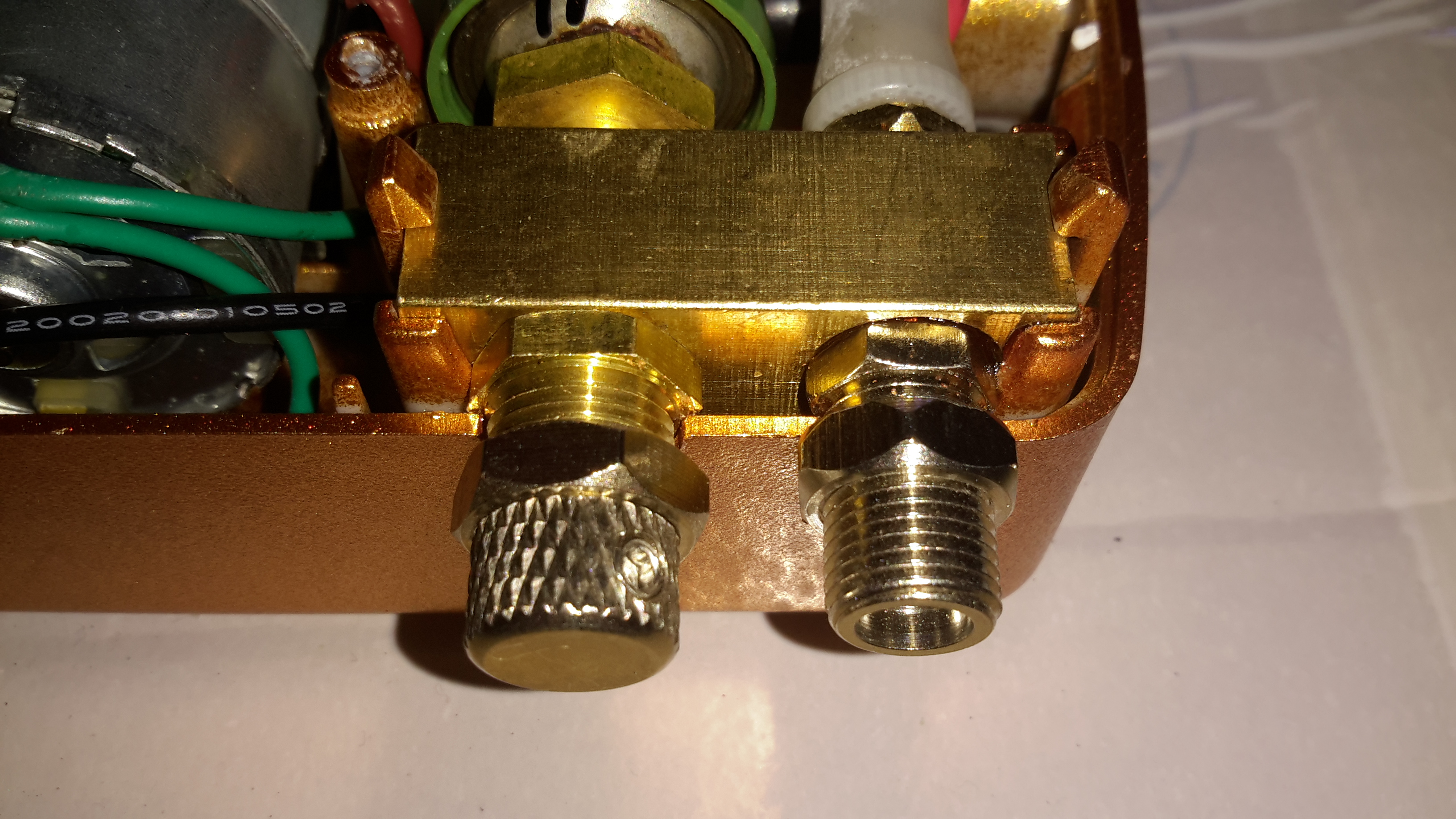
Air Block
Next to the air outlet fitting is an adjustment knob, supposedly for varying the pressure. However it’s just a piss-poorly designed adjustable relief valve that vents to atmosphere. There’s not much of a control range.
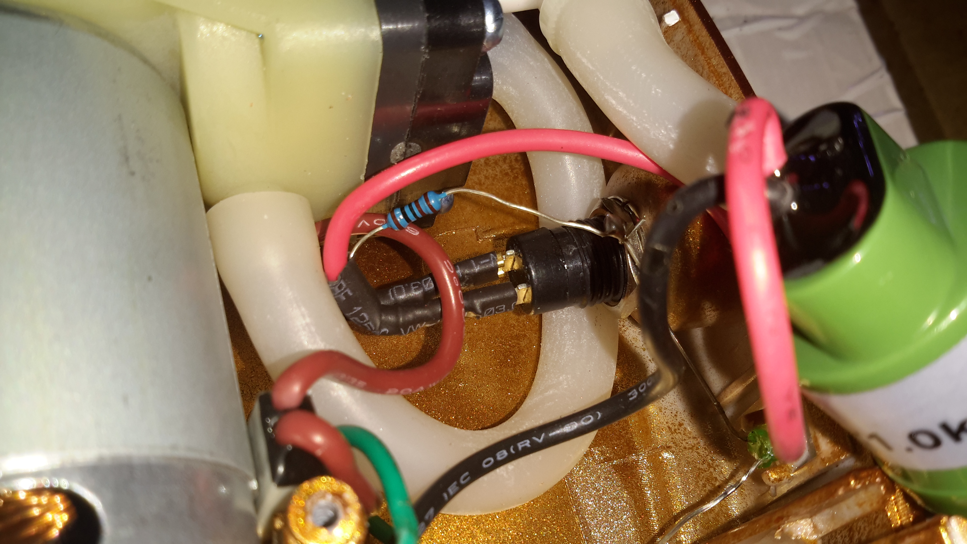
Messy Wiring
The wiring gets a bit messy where the power LED is concerned, with no heatshrink over the solder joints, but it’s adequate.
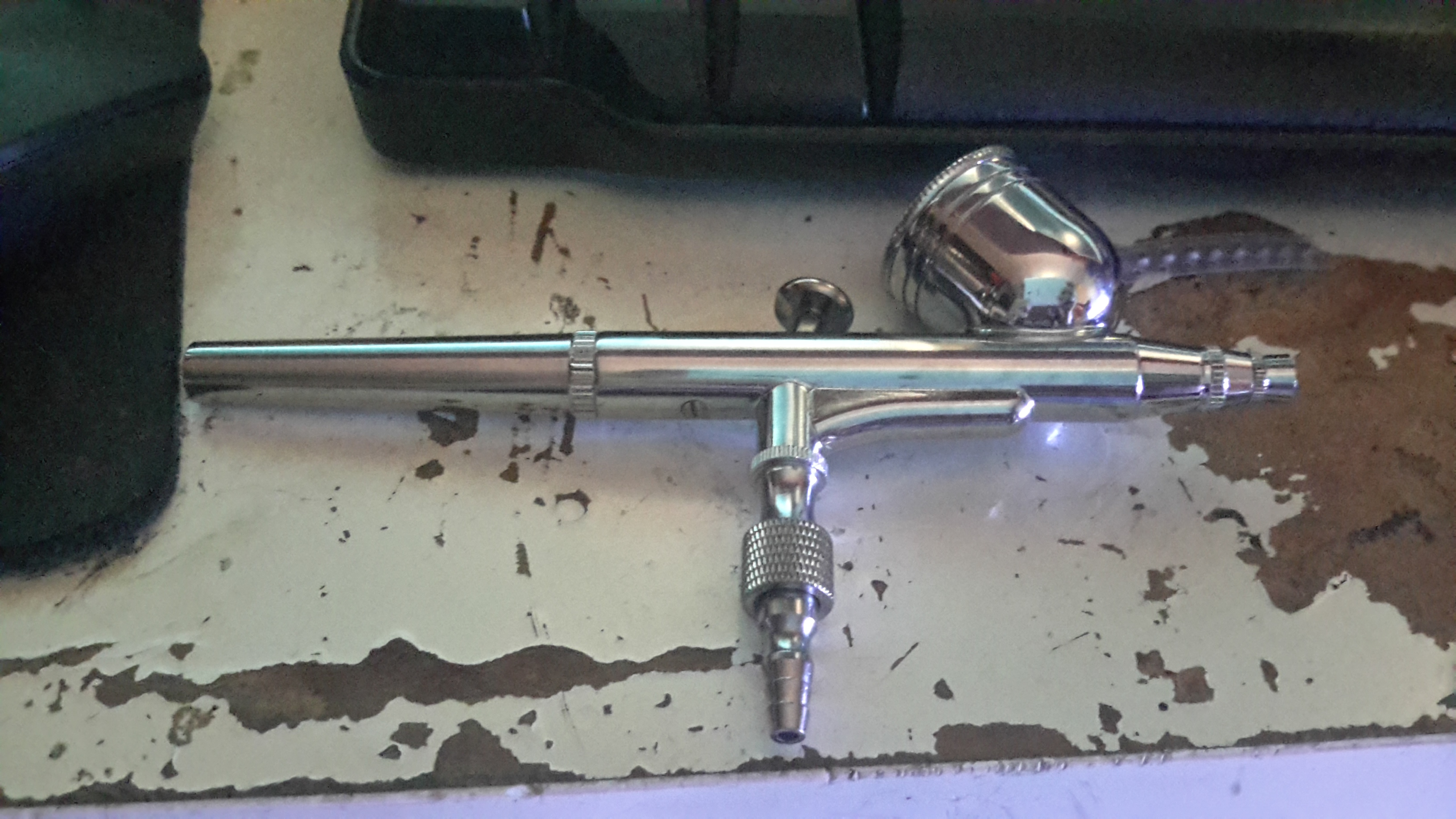
Airbrush
The airbrush itself isn’t too bad. It’s solid Brass, with a very nice Chrome finish. I’m not expecting miracles from a very cheap tool, but it certainly seems to be reasonable.
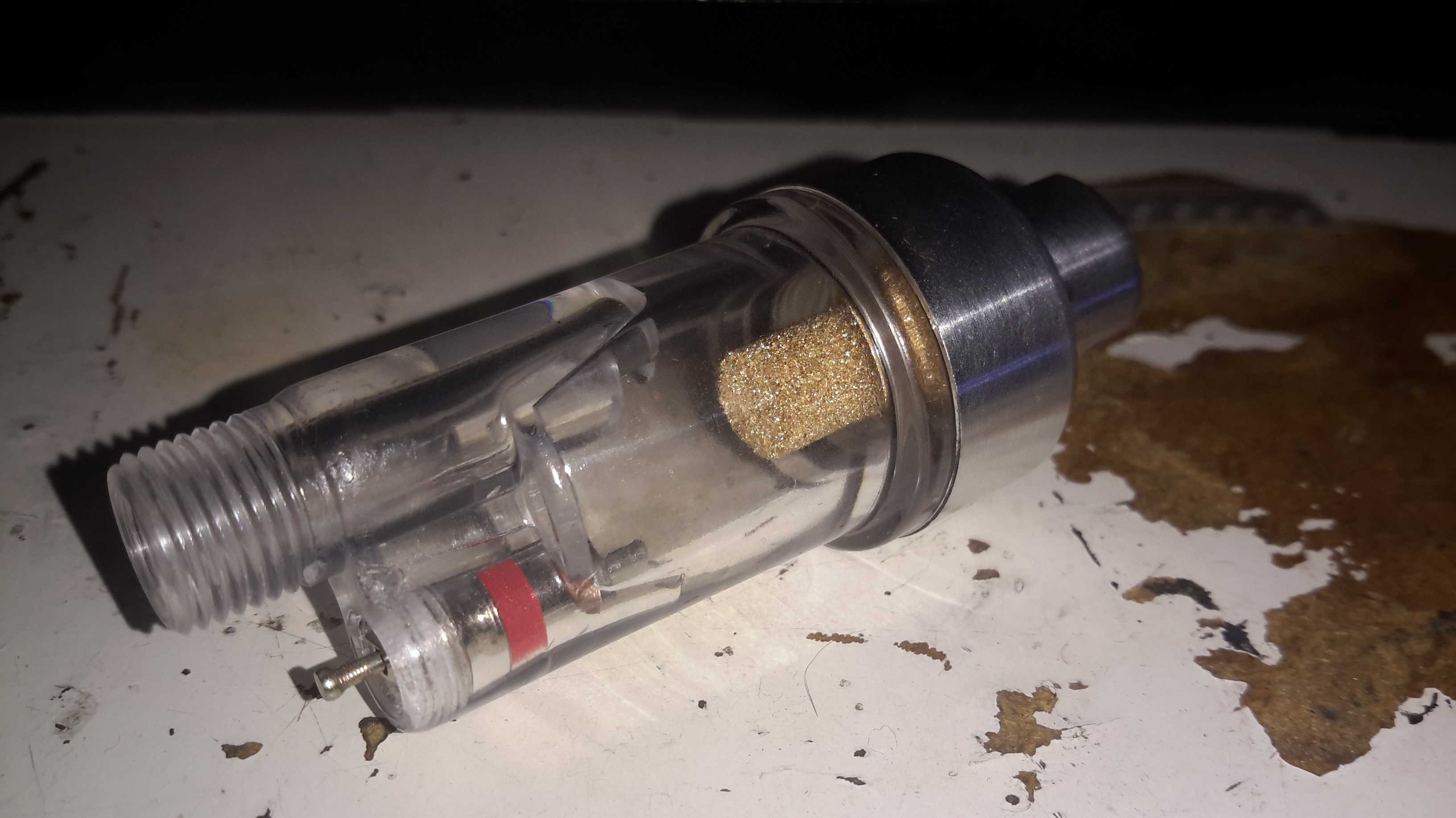
Water Trap
A moisture trap is supplied for the brush, to prevent water drops being sprayed out with the paint. Very handy.
Since the 4×18650 battery pack supplied with my Cree head torch is pretty shit, even by China’s standards, I figured something I could put my own cells into would be a better option. An eBay search turned up these battery boxes, not only with a direct battery output for my torch, but also a USB port for charging other devices when I’m low on charge.
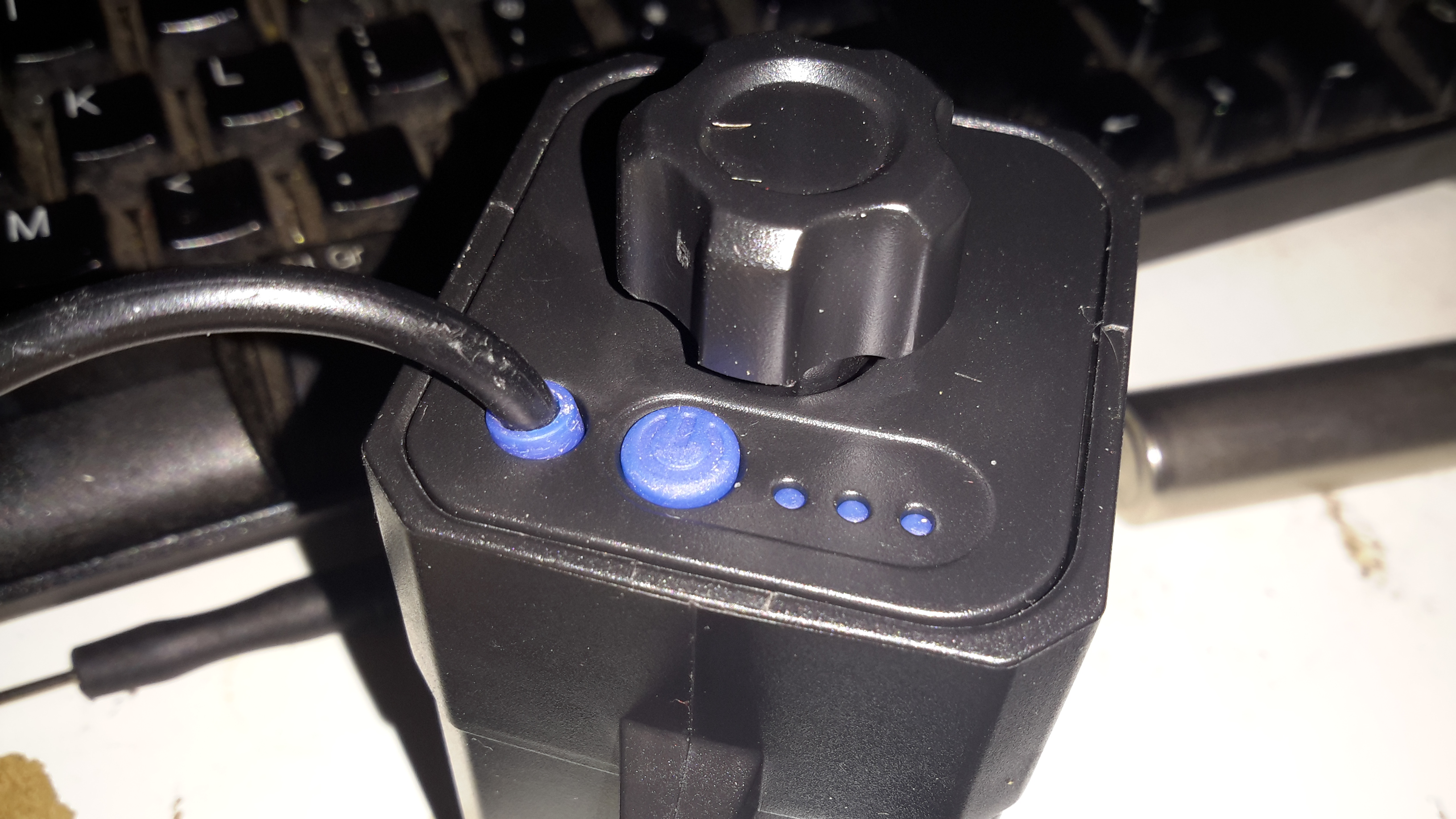
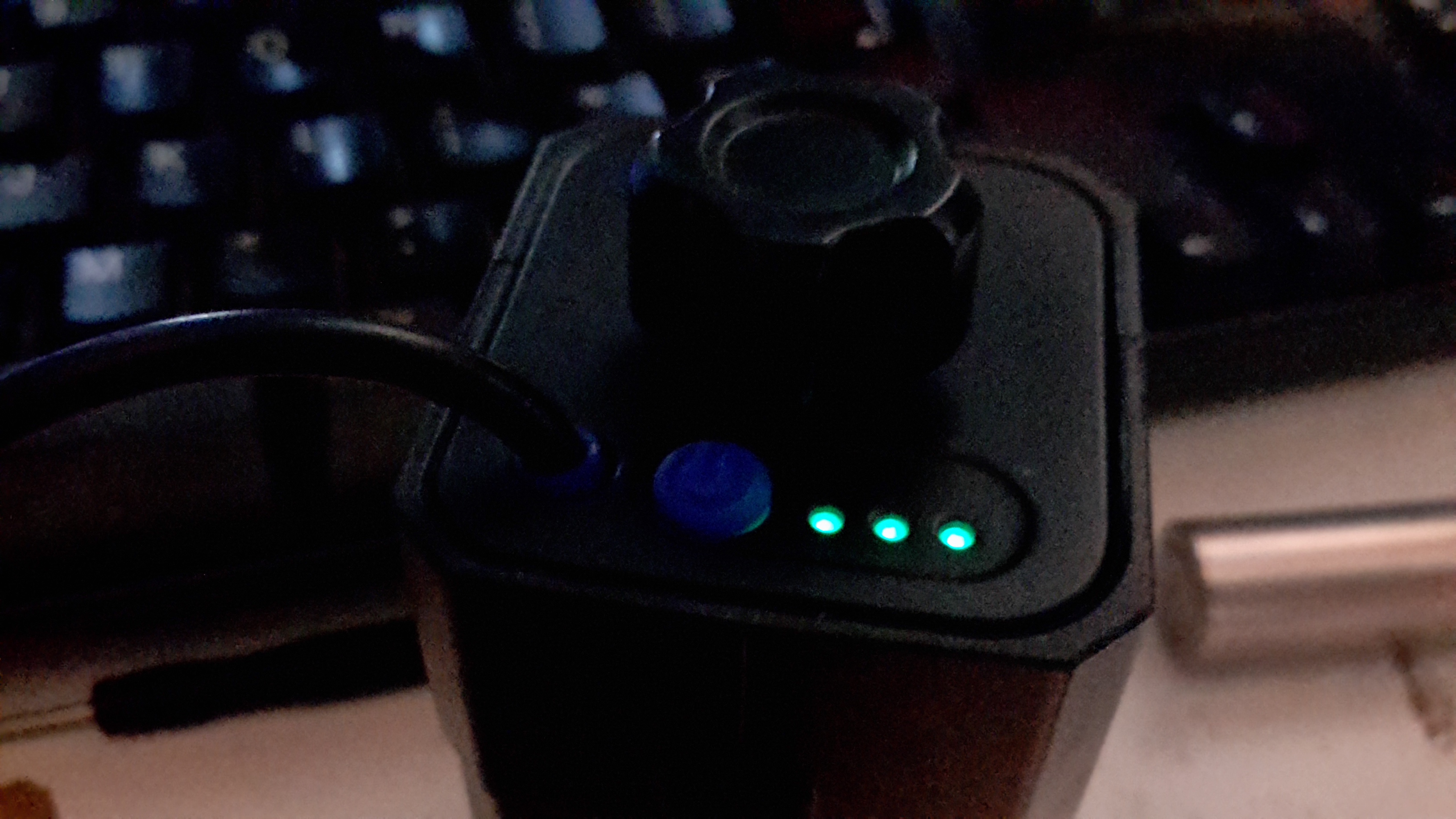
LED Capacity Indicator
The output to the lamp connector is directly connected to the battery, through the usual Lithium Ion protection, but the USB output is controlled from a single power button. Battery charge condition is displayed on 3 LEDs. Not sure why they used blue silicone for the seal & then used green LEDs… But it does work, even if a little dim.
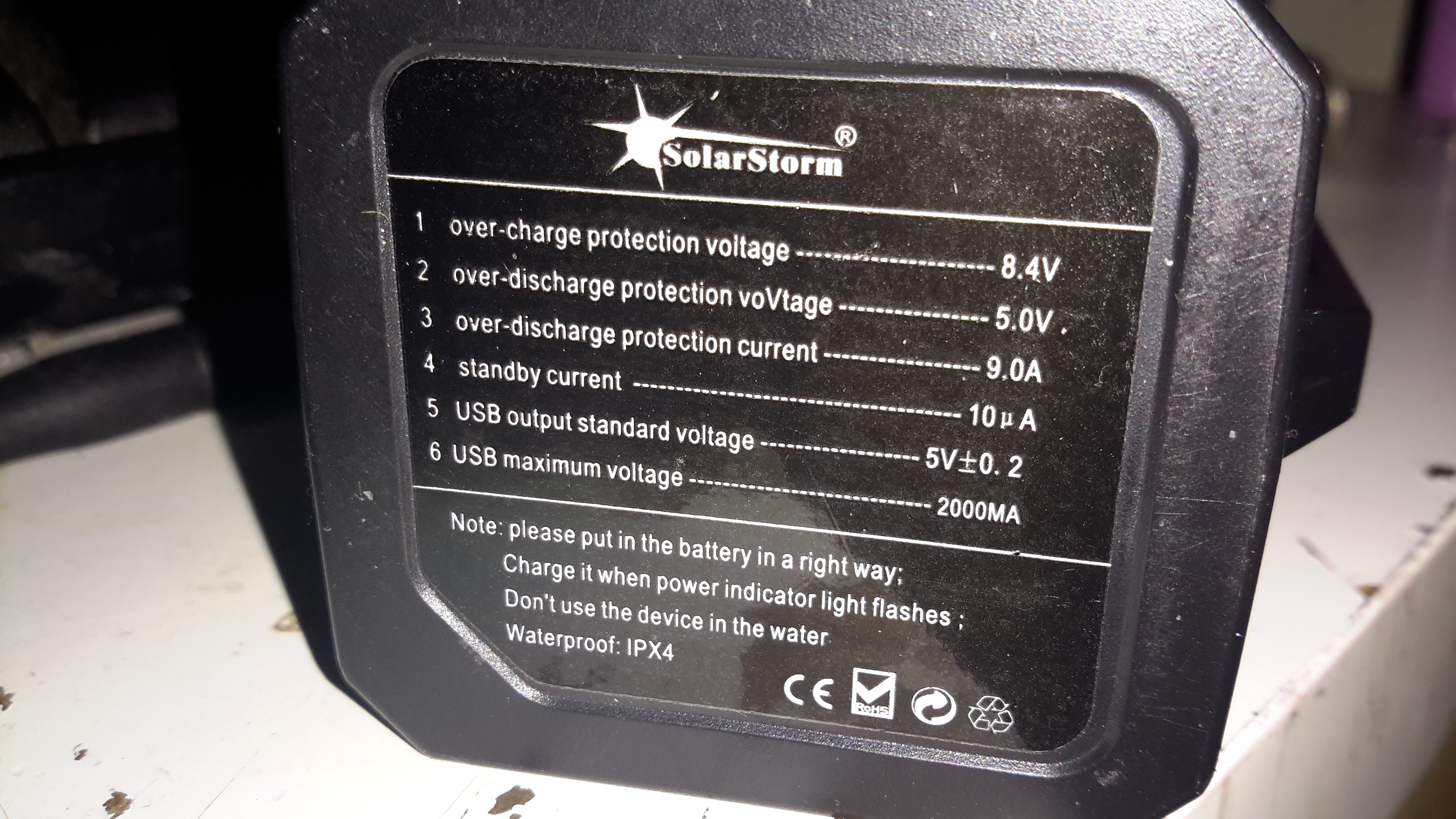
Label
Essential information. Does claim to be protected, and from the already existing electronics for the USB this would be expected in all but the cheapest crap.
An IP rating of IPX4 is claimed, yet just above that rating is a notice not to be used in water. Eh?
This is sealed with an O-Ring around the edge of the top cap & silicone seals around the cable & retaining screw. I did test by immersion in about 6″ of water, and it survived this test perfectly fine, no water ingress at all.
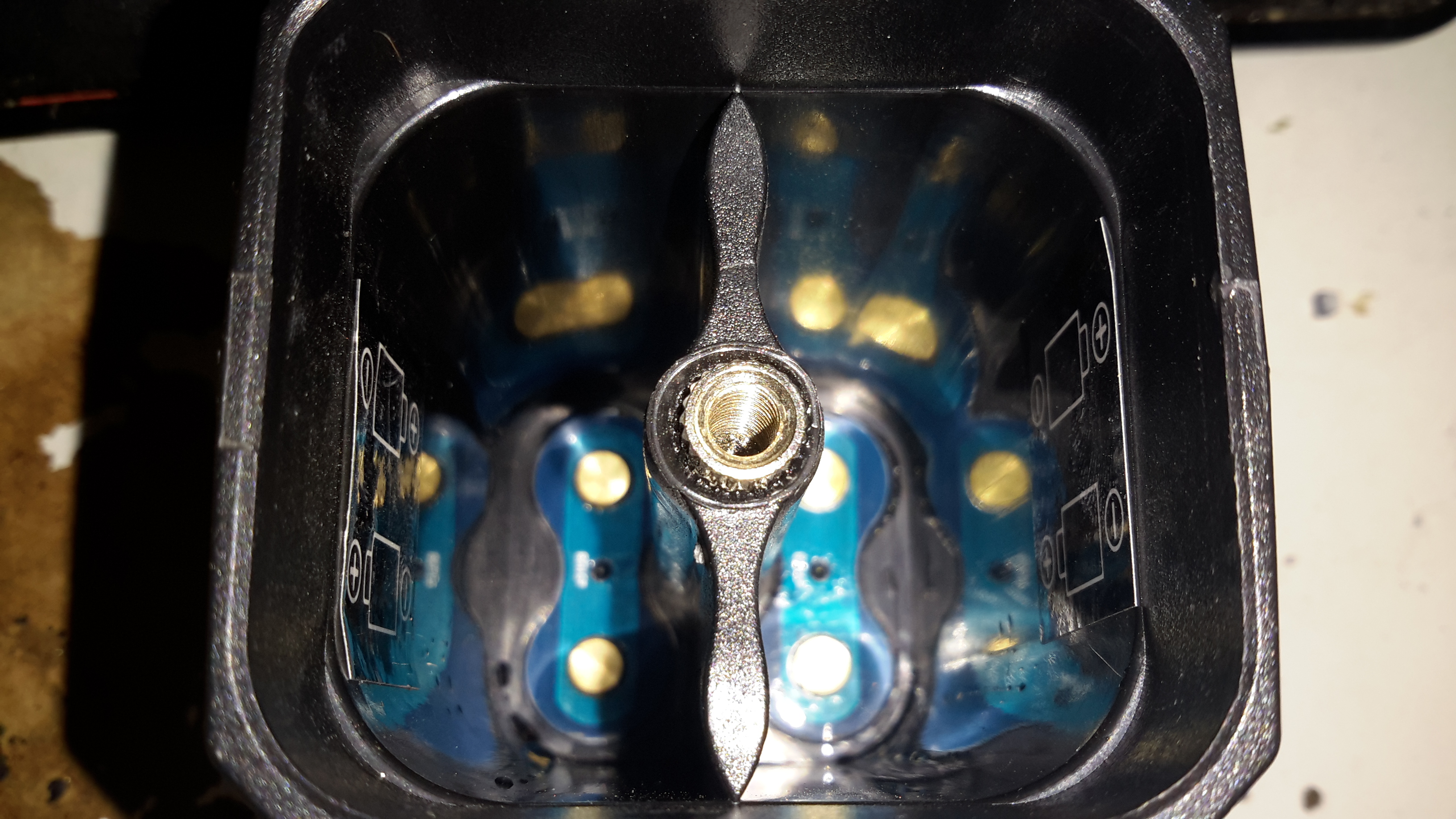
Interconnect Straps
The casing holds a PCB at the bottom end with the cell straps.
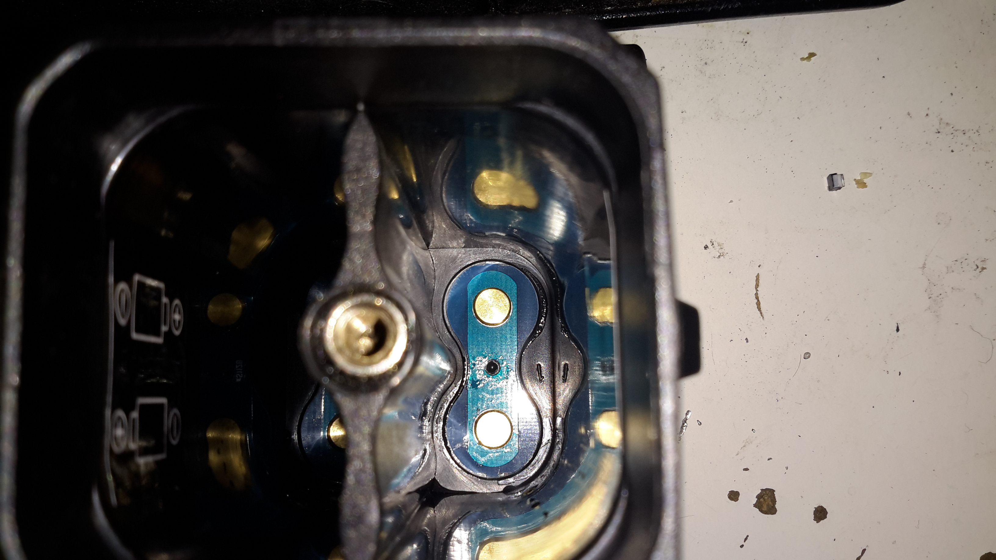
Screw Post
Someone wasn’t that careful at getting the brass screw insert properly centred in the injection mould when they did this one. It’s mushed off centre, but i’s solidly embedded & doesn’t present any problems to usability.
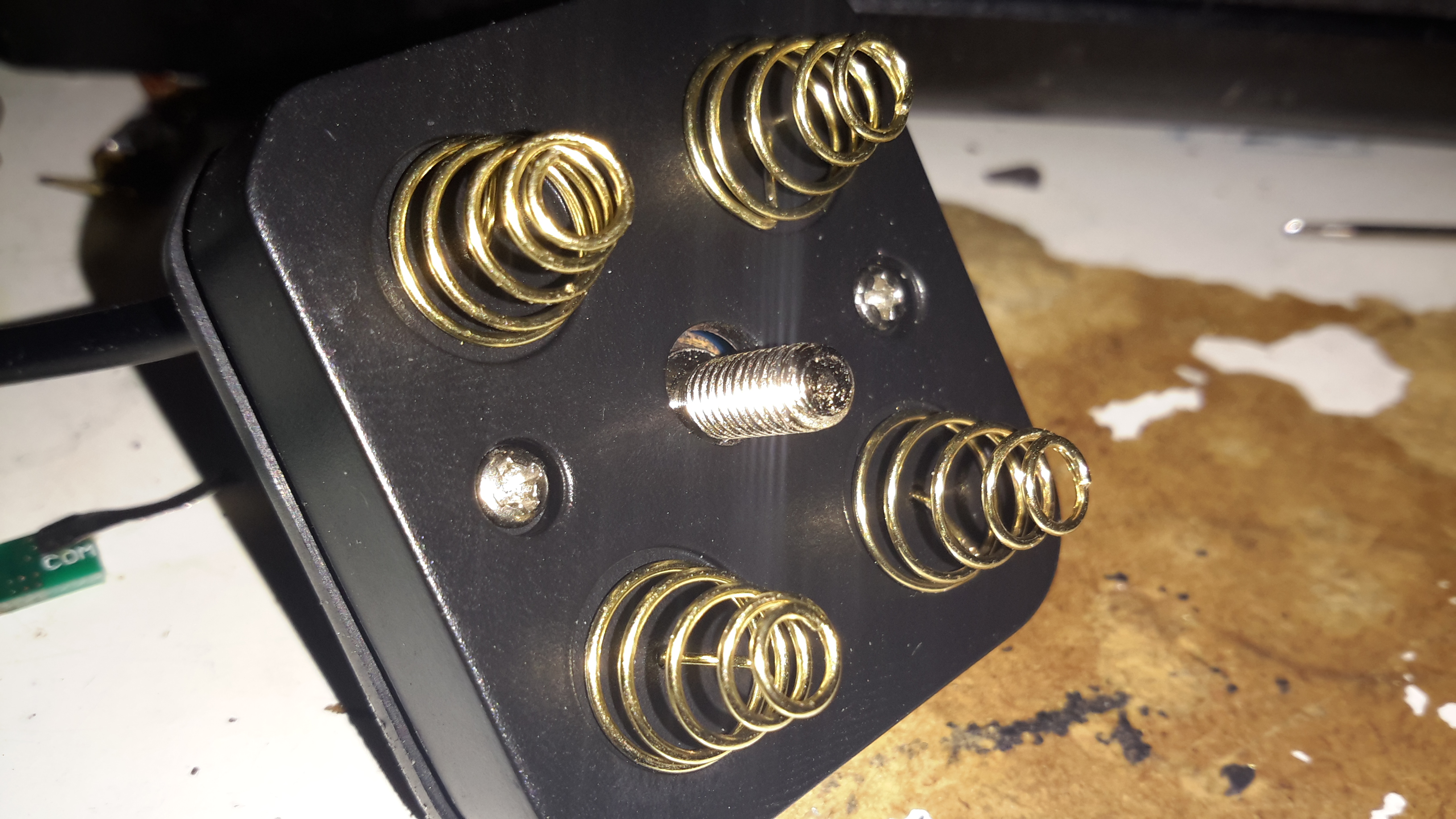
Cell Springs
The top cover holds the cell springs & the electronics.
Button & Cable Seal
Removing the pair of screws allows the top cap to open up. The cable, button & LEDs are robustly sealed off with this silicone moulding.
Top Removed
Here’s the PCB, not much on the top, other than the power button & battery indicator LEDs.
Electronics
Desoldering the cell springs allows the PCB to pop out of the plastic moulding. There’s more than I expected here!
Bottom left is a DC-DC converter, generating the +5v rail for the USB port, this is driven with an XL1583 3A buck converter IC.
Bottom right is the protection IC & MOSFETs for the Lithium Ion cells. I wasn’t able to find a datasheet for the tiny VA7022 IC, but I did manage to make certain it was a 7.4v Li-Ion protection IC.
Top right is a completely unmarked IC, and a 3.3v SOT-23 voltage regulator. I’m assuming that the unmarked IC is a microcontroller of some sort, as it’s handling more than just the battery level LEDs.
A pretty decent 4-core cable finishes the job off. For once there’s actually some copper in this cable, not the usual Chineseuim thin-as-hair crap.
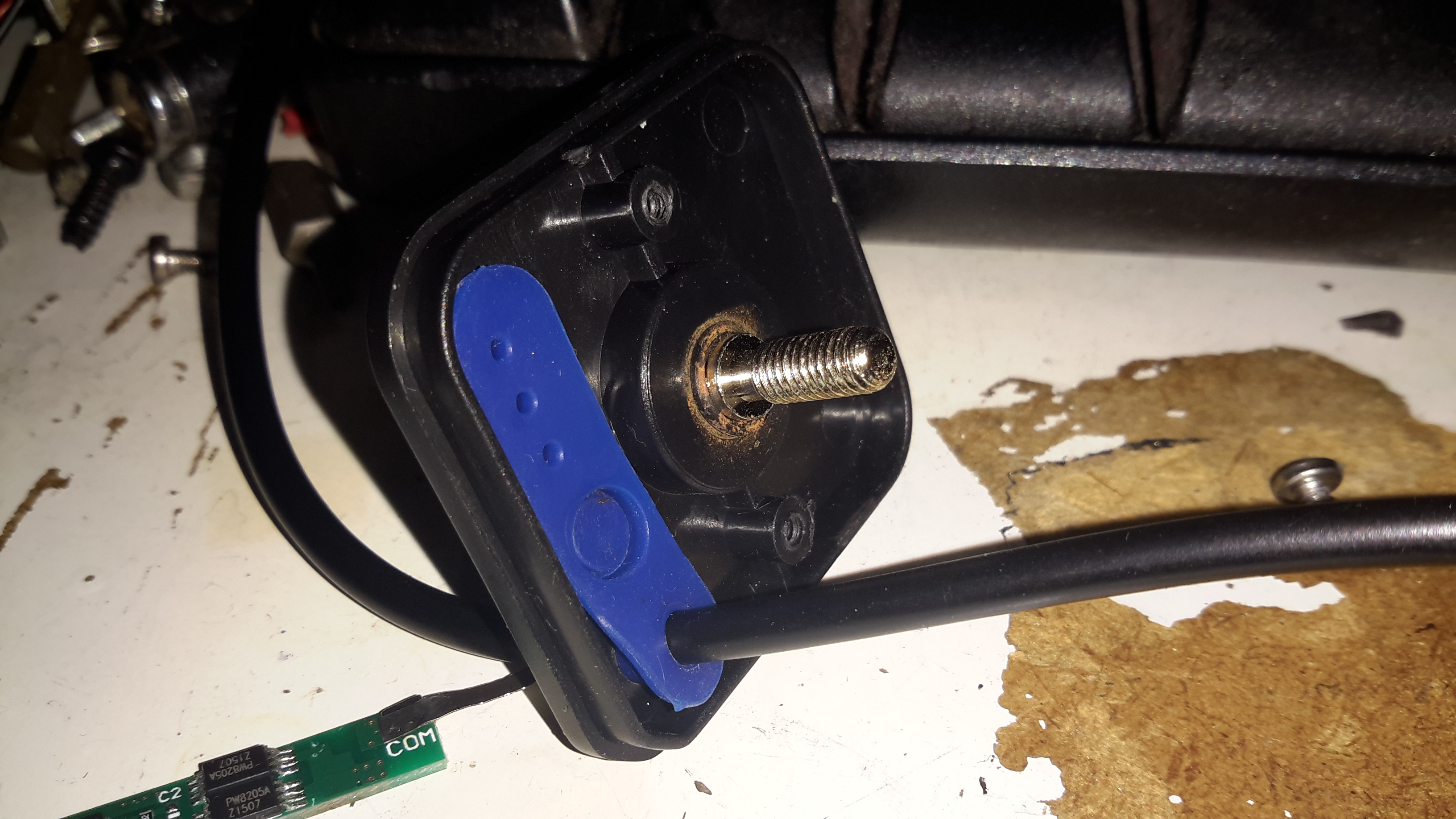
Here’s another Dyson teardown, in my efforts to understand how marketing have got hold of relatively simple technology & managed to charge extortionate amounts of money for it.
This is the DC35, the model after the introduction of the brushless digital motor.
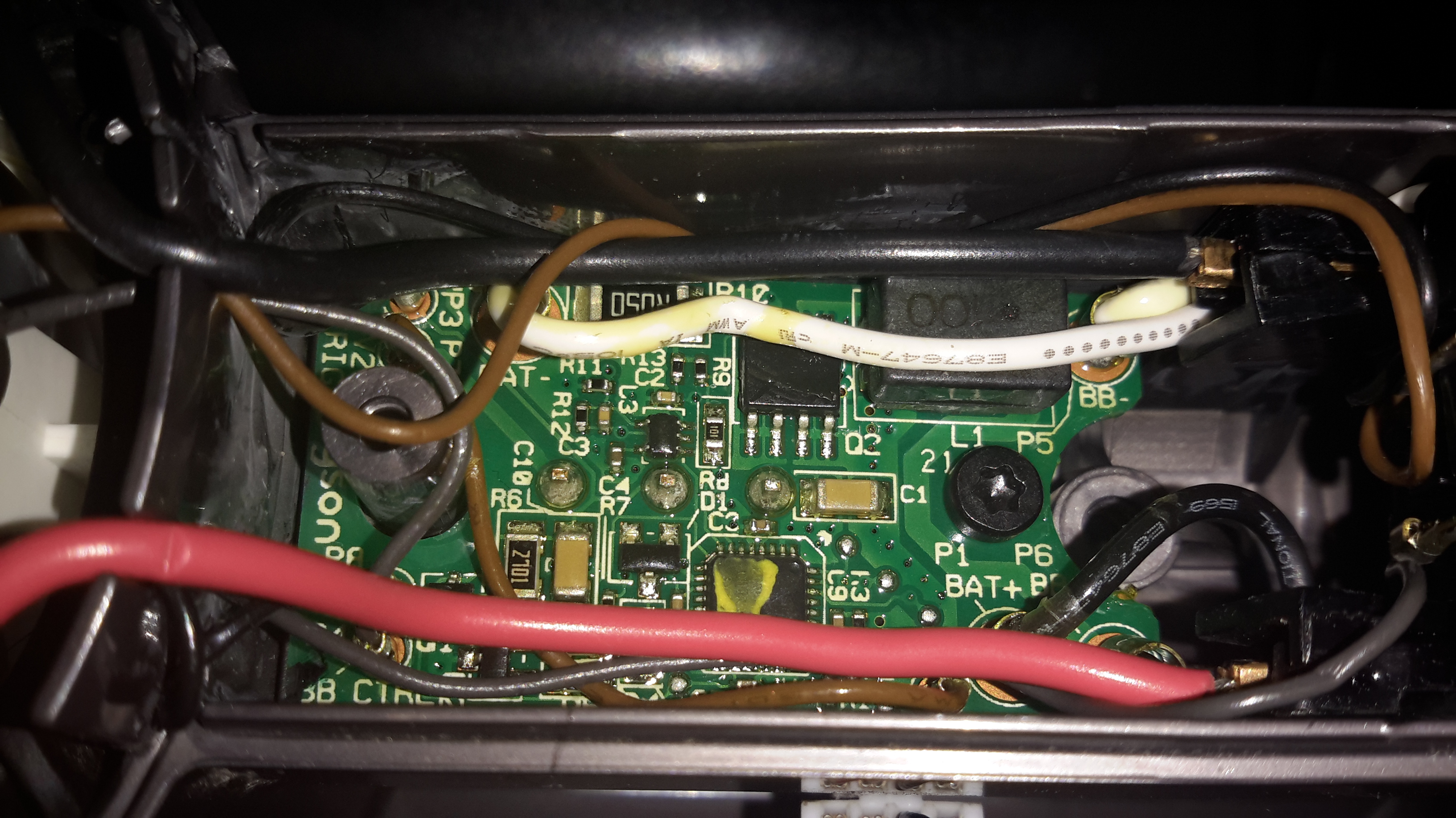
Back Cap Removed
On this version the mouldings have been changed, and the back cover comes off, after removing the battery retaining screw. It’s attached with some fairly vicious clips, so some force is required. Once the cap is removed, all the electronics are visible. On the left is the motor itself, with it’s control & drive PCB. There’s another PCB on the trigger, with even more electronics. The battery connector is on the right.
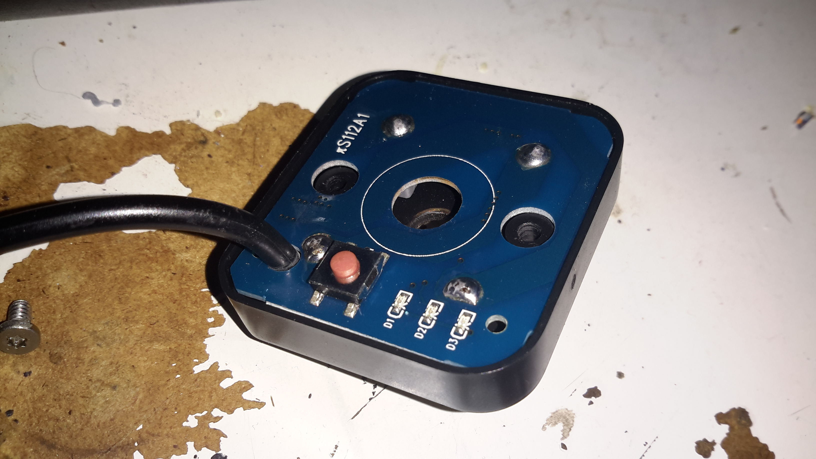
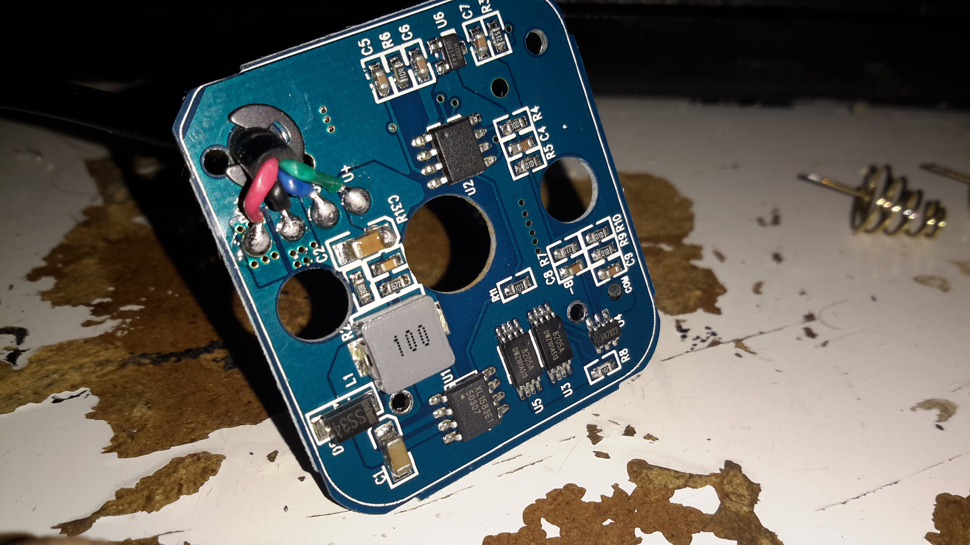
Trigger PCB
Here’s the trigger PCB, which appears to deal with DC-DC conversion for powering the brush attachments. The QFN IC with yellow paint on it is an Atmel ATTiny461 8-bit microcontroller. This is probably controlling the DC-DC & might also be doing some battery authentication.
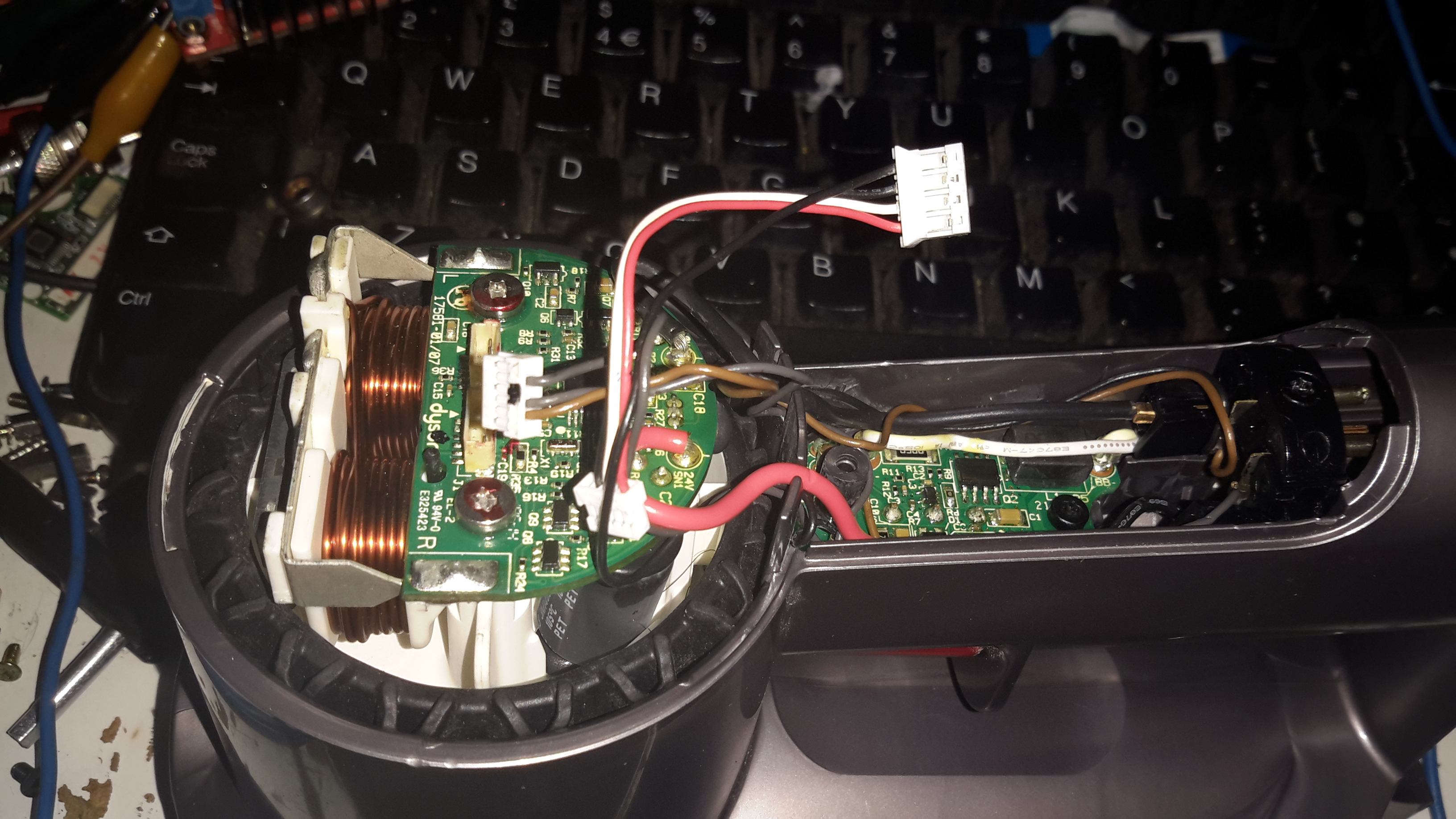
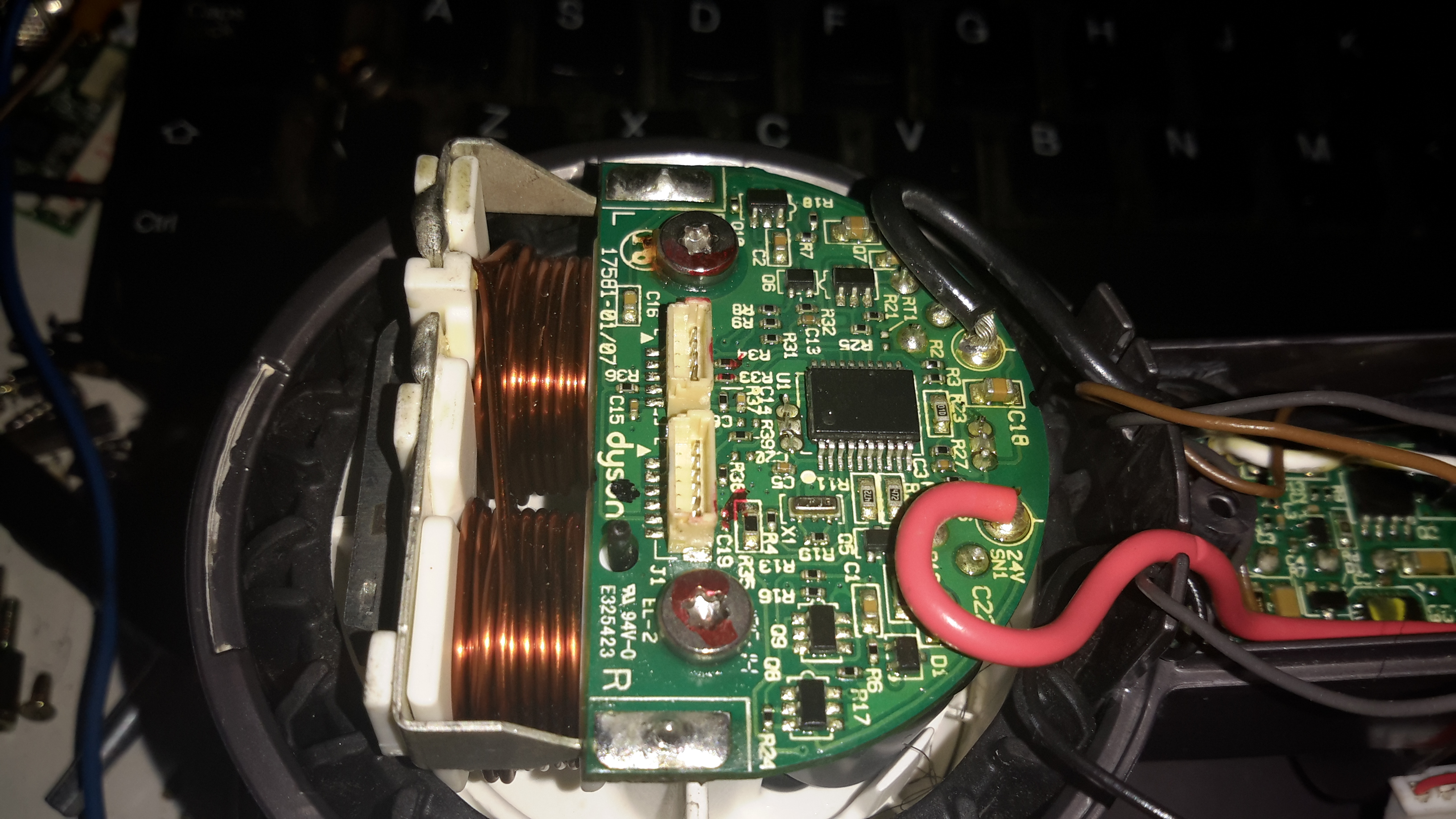
“Digital Motor”
Here’s the motor & it’s board. The windings on the stator are extremely heavy, which makes sense considering it’s rated at 200W. The main control IC is a PIC16F690 from Microchip. Instead of using an off the shelf controller, this no doubt contains software for generating the waveforms that drive the brushless motor. It also appears to communicate with the other PCBs for battery authentication.
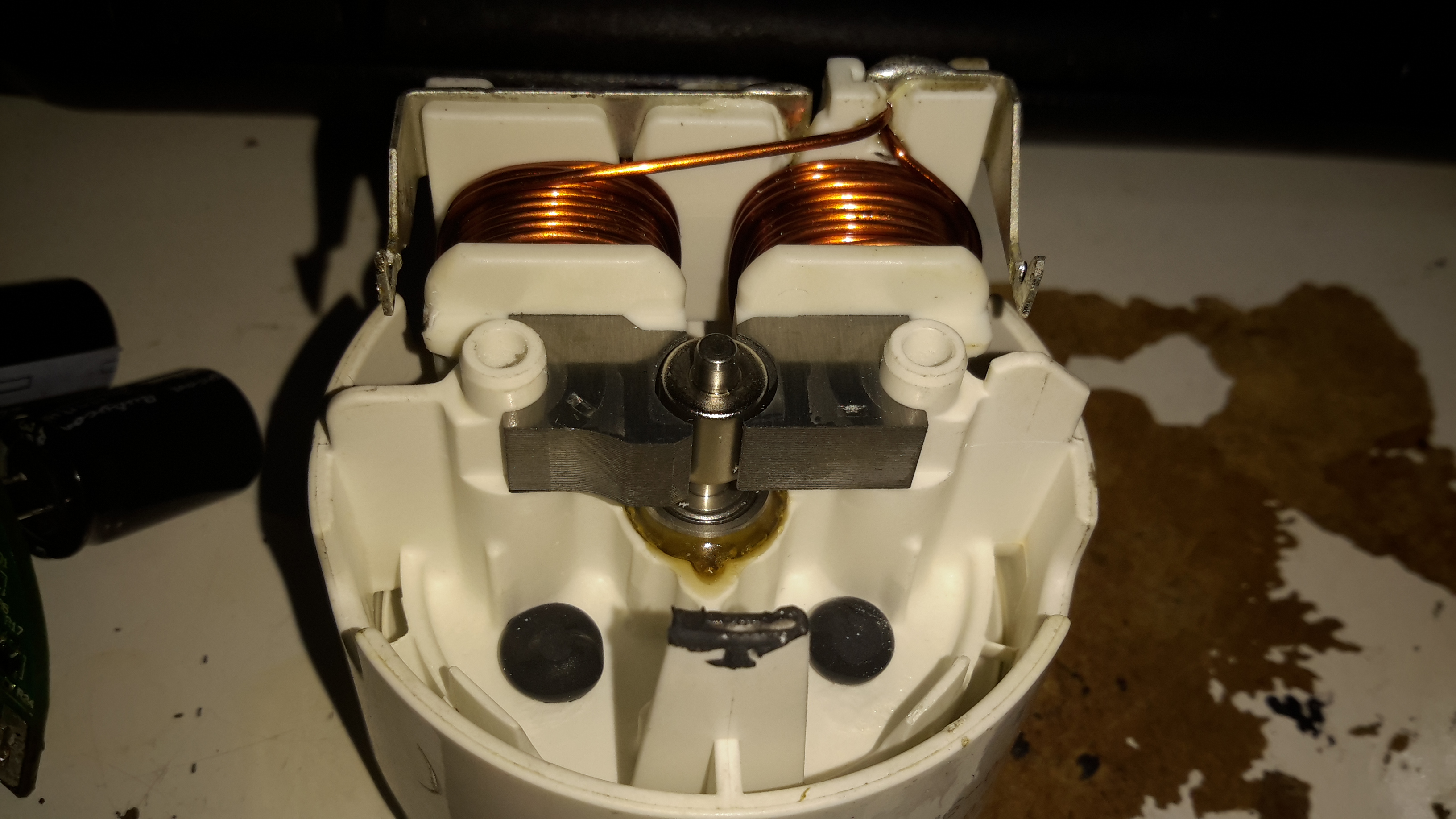
Stator
Desoldering the board allows it to be removed from the motor itself. The pair of windings are connected in anti-phase, to create alternating North-South poles depending on polarity. Since the existing controller is unusable due to software authentication with the other parts, I might have a go at building my own driver circuit for this with an Arduino or similar.
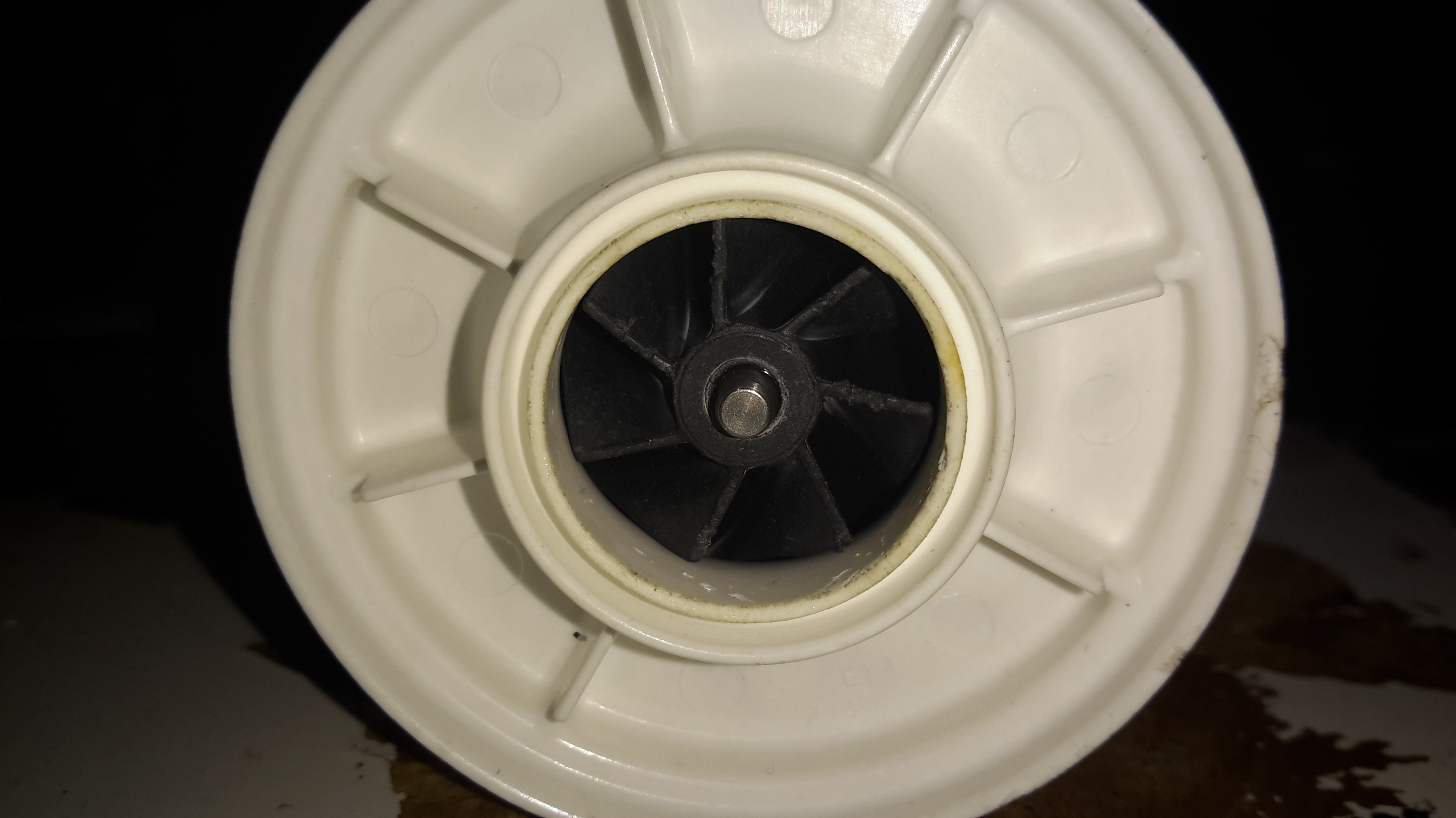
Blower Assembly
The blower assembly is simple plastic mouldings, pressed together then solvent welded at the seam.
Impeller
The impeller is just a centrifugal compressor wheel, identical to what’s used in engine turbochargers.
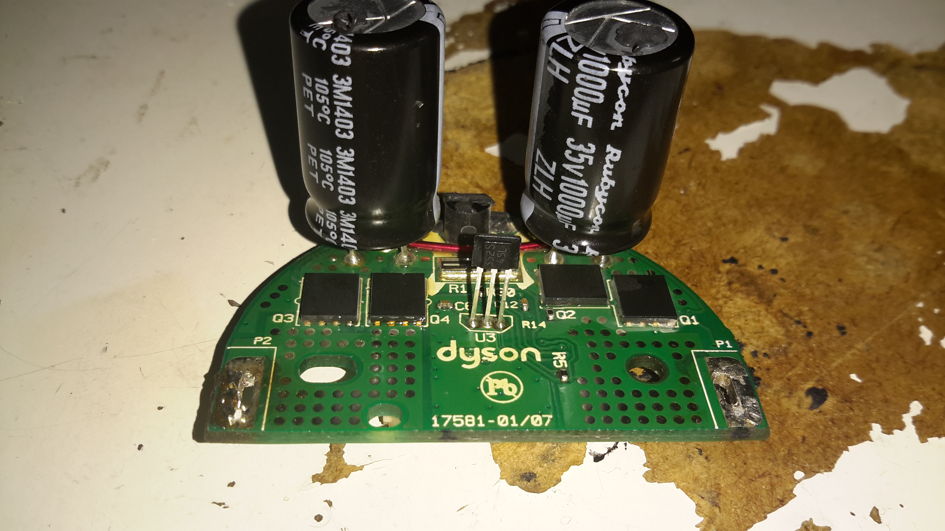
Motor Control Board
The inside face of the control PCB holds the 4 very large MOSFETs, IRFH7932PbF from International Rectifier. These are rated at 30v 20A a piece, and are probably wired in a H-Bridge. There’s a bipolar Hall switch to sense rotor position & rotation speed, and an enormous pair of capacitors on the main power bus.
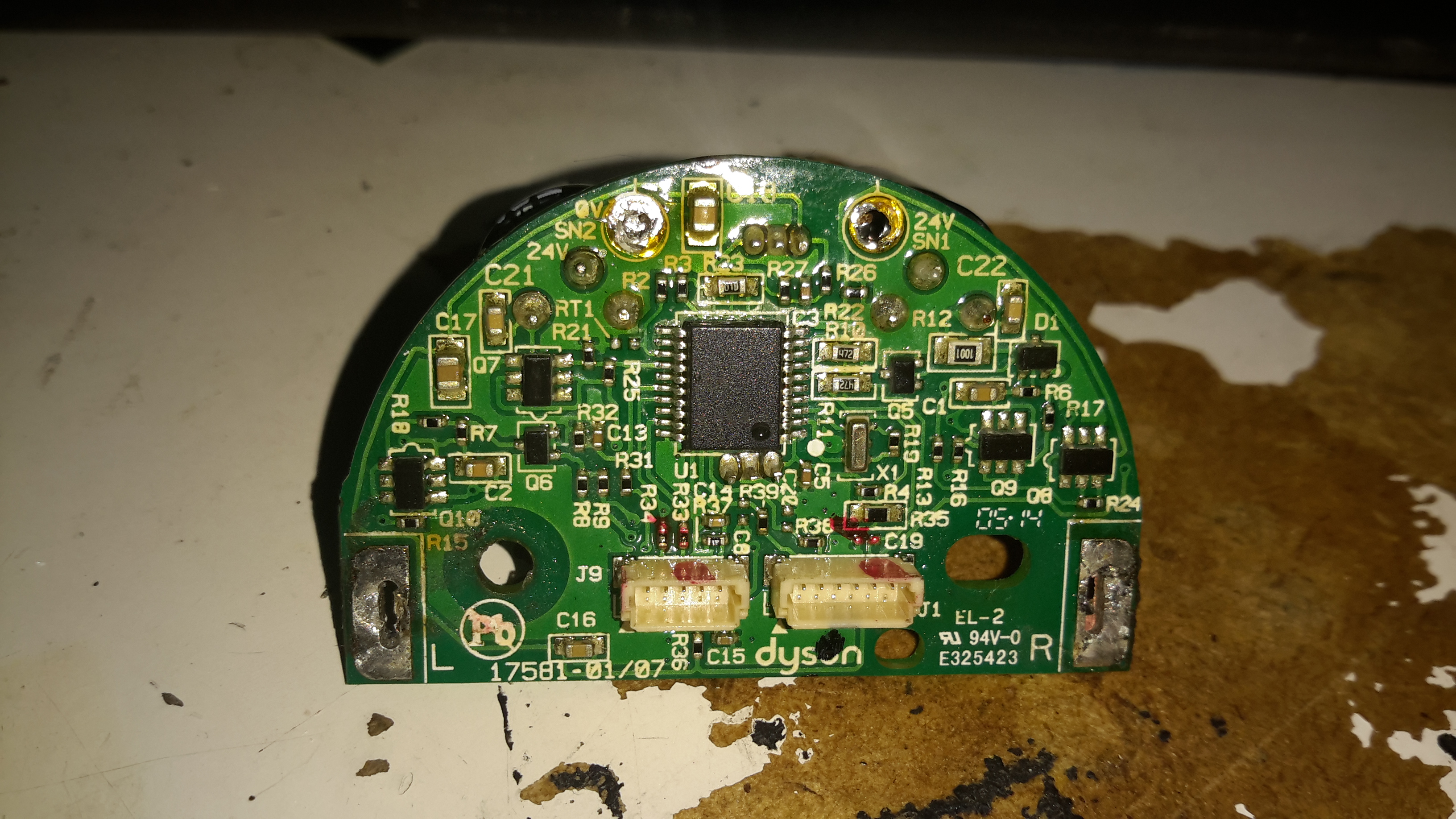
Motor Control Board Reverse
Not much on the other side of the PCB other than the microcontroller and associated gate drive stuff for the FETs.
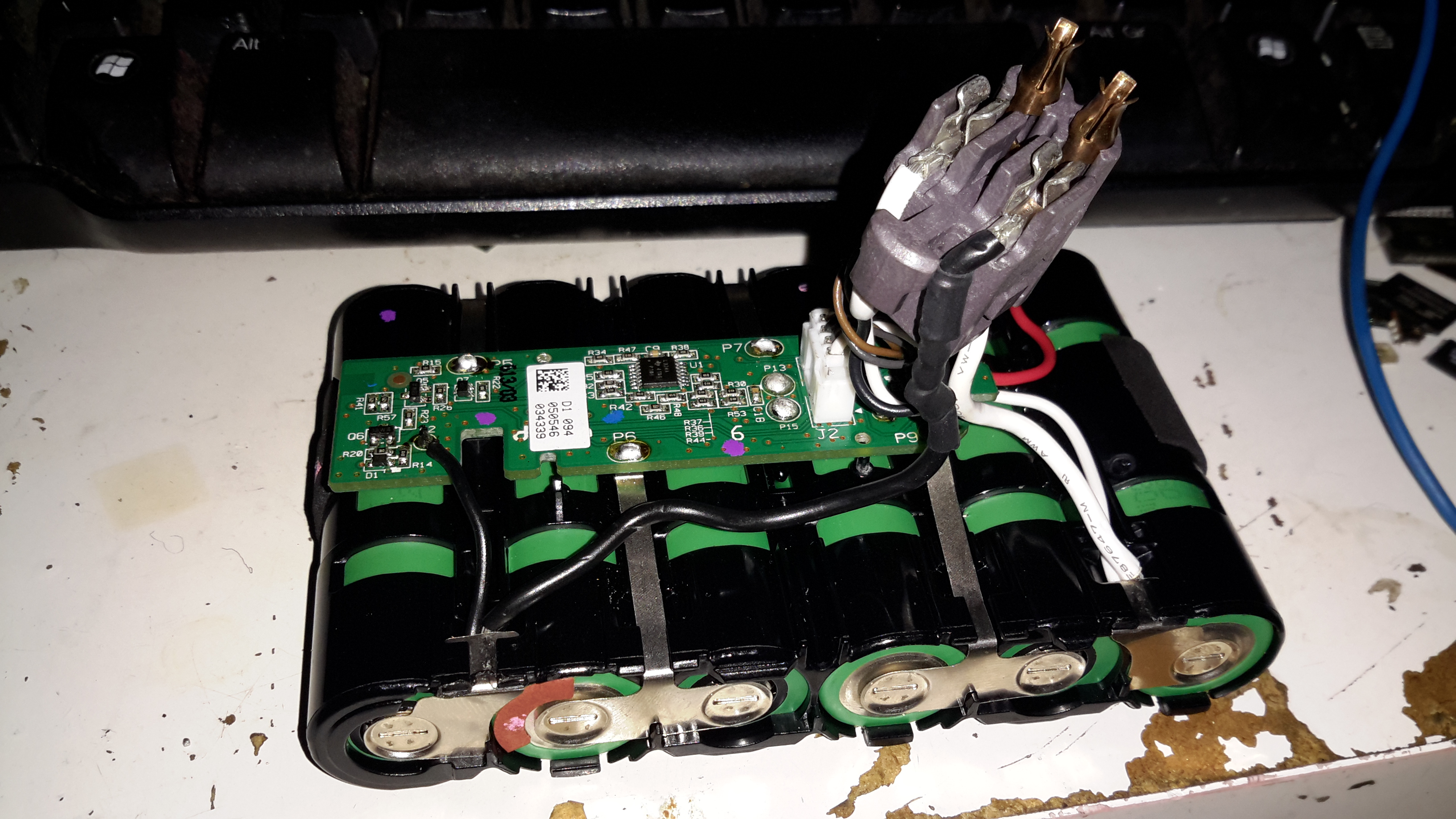
Battery Pack Opened
The battery pack is similar to the DC16 in it’s construction, a heavily clipped together plastic casing holding 6 lithium cells. In this one though there’s a full battery management system. The IC on the top of the board above is a quad Op-Amp, probably for measuring cell voltages.
Battery BMS Bottom
The other side of the BMS board is packed with components. I wasn’t able to identify the QFN IC here, as it’s got a custom part number, but it’s most definitely communicating with the main motor MCU via I²C over the two small terminals on the battery connector.
Since this is the 300th post on my blog in the 6 years I’ve been at this, I figured I’d do a post with recent site updates & some news.
Site Look
There haven’t been many updates to the general look of the site for quite a while, with some help of a friend I managed to get a new ticker added to the header, which saves on post count for upcoming projects & posts.
The header image is also dynamic, picking randomly from a collection of images, mostly from previous posts, and a few that started as messing about with a camera & turned out looking quite good.
Site Support
Also added to the site’s look is a Tip Jar on the right hand side, so thankful readers can donate something if I’ve managed to post something remotely helpful ;).
People that know me personally know I hate ads with a passion, and as such ads will have no place on my blog for as long as it’s visible on the intertubes. The site does cost quite a significant (to me anyway) amount of cash to keep going, not to mention time, so any donations would be more than welcome!
Radio-Based Posts
I haven’t done any proper Ham Radio based posts in quite a while, mainly due to me not having anything to share on the subject, unfortunately it can be a damn expensive hobby & there are other things taking priority at the moment. (Apparently eating & warmth are essentials, according to the missus at least ;)).
There is going to be a round-about radio based post shortly though, so my Ham readers stay tuned!
Boating Posts
Now that we’re in the new year, when the weather returns to something remotely tolerable to be outdoors in, there’ll be much more boating related stuff on the cards, not only trips but engineering jobs onboard.
The Dyson DC16 is one of the older handheld vacuums, before the introduction of the “Digital Motor”. (Marketing obviously didn’t think “Switched Reluctance Motor” sounded quite as good).
These vacuums have a very large DC brush motor driving the suction turbine instead, the same as would be found in a cordless power tool.
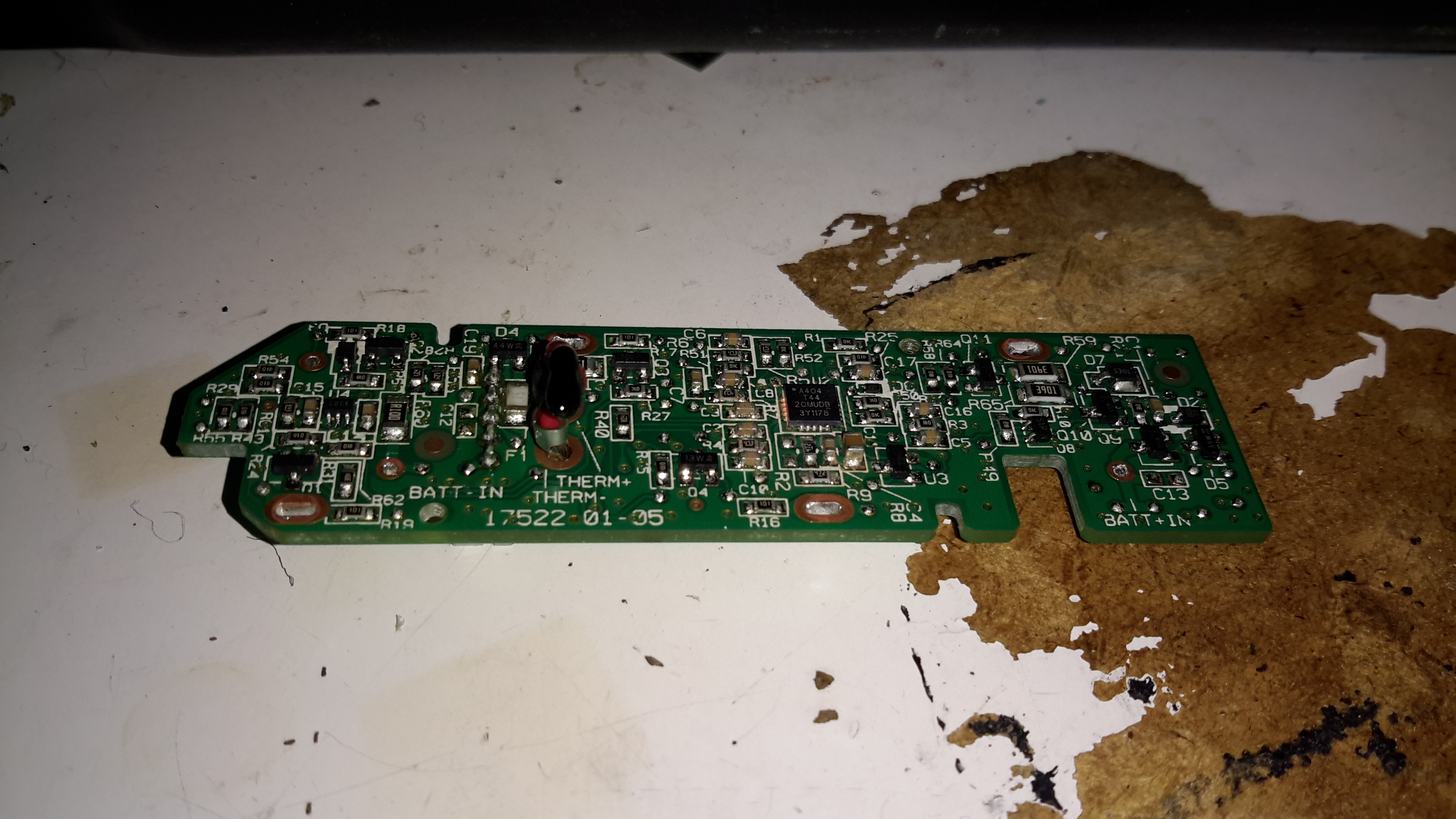
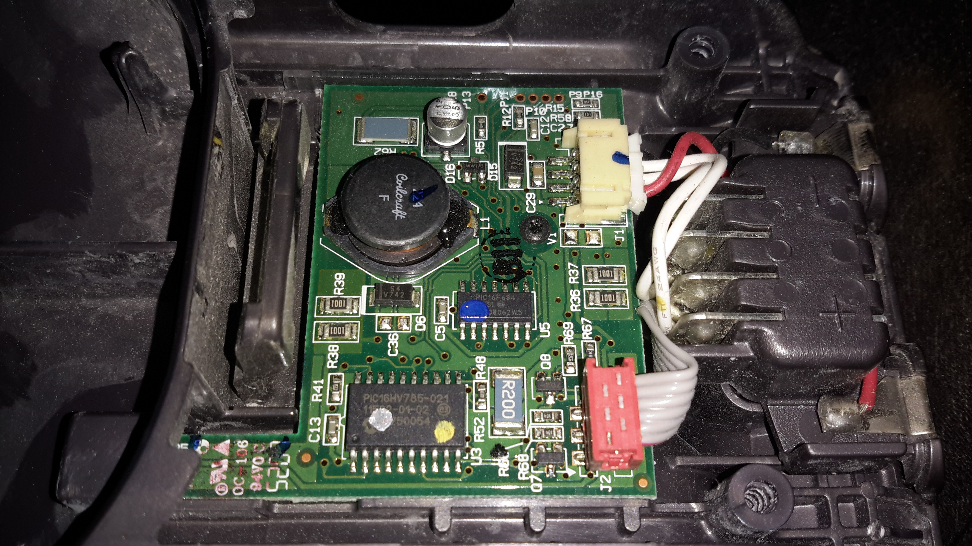
Control PCB
Popping the front cap off with the ID label, reveals the brains of the vacuum. The two large terminals at the right are for charging, which is only done at 550mA (0.5C). There are two PIC microcontrollers in here, along with a large choke, DC-DC converter for supplying the logic most likely. The larger of the MCUs, a PIC16HV785, is probably doing the soft-start PWM on the main motor, the smaller of the two, a PIC16F684 I’m sure is doing battery charging & power management. The motor has a PCB on it’s tail end, with a very large MOSFET, a pair of heavy leads connect directly from the battery connector to the motor.
Just out of sight on the bottom left edge of the board is a Hall Effect Sensor, this detects the presence of the filter by means of a small magnet, the vacuum will not start without a filter fitted.
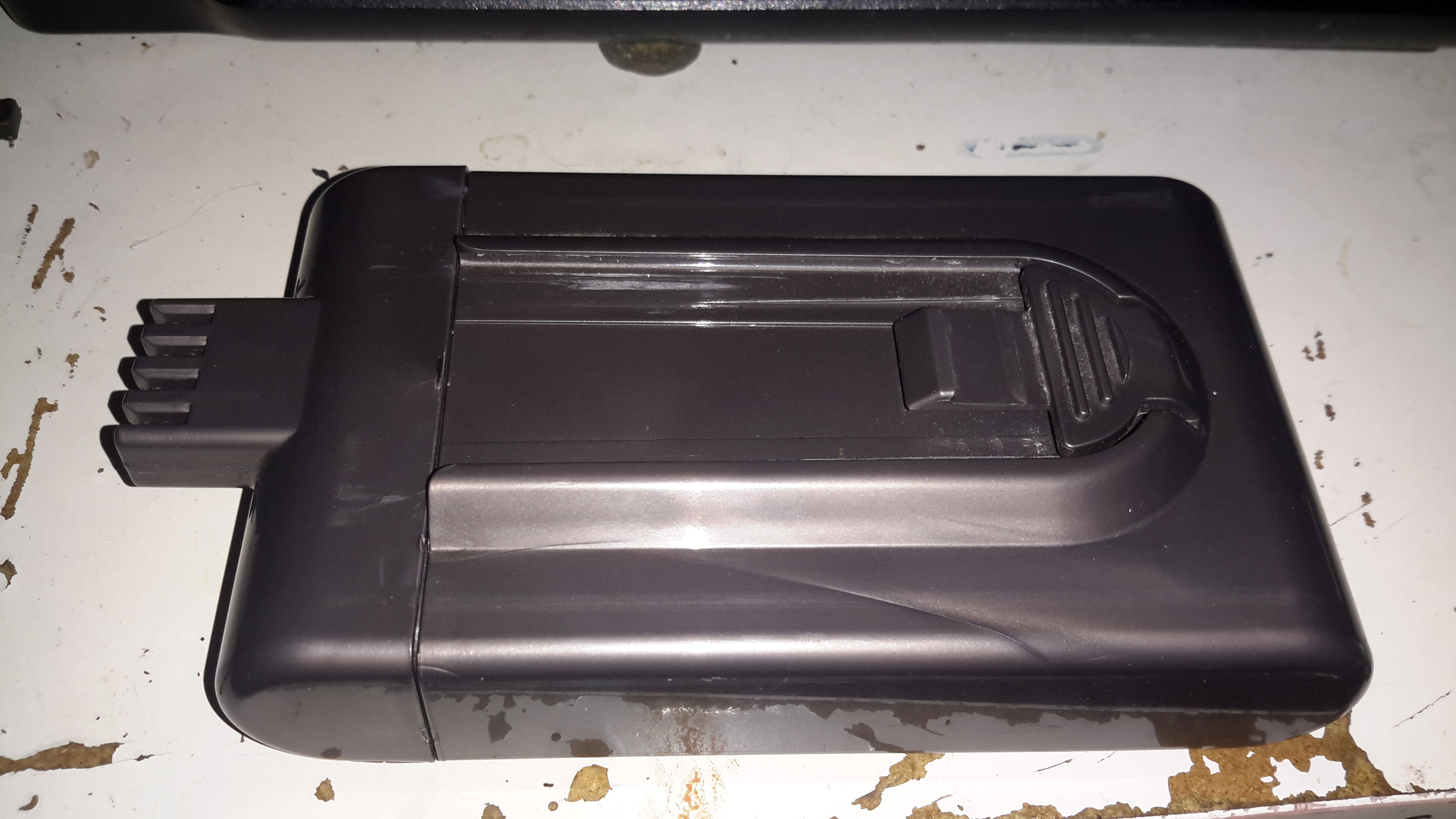
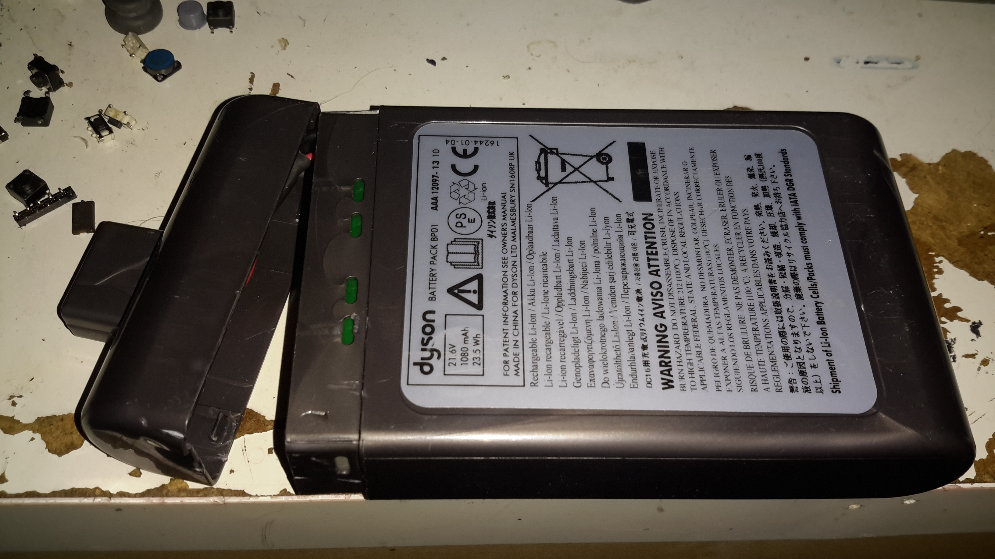
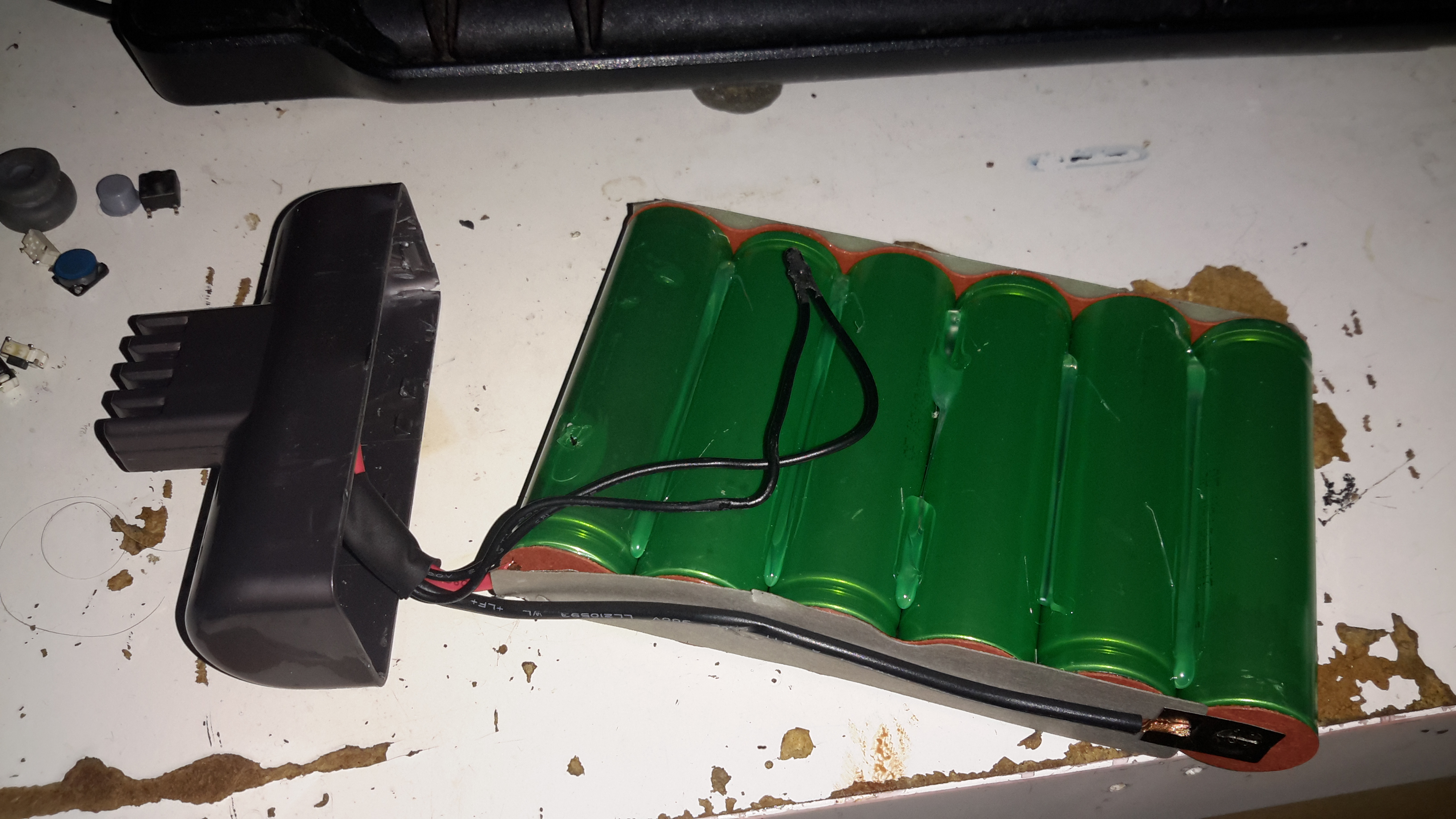
Battery Pack
The battery pack is a large custom job, obviously. 4 terminals mean there’s slightly more in here than just the cells.
Battery Cracked
Luckily, instead of ultrasonic or solvent welding the case, these Dyson batteries are just snapped together. Some mild attack with a pair of screwdrivers allows the end cap to be removed with minimal damage.
Cells
The cells were lightly hot-glued into the shell, but that can easily be solved with a drop of Isopropanol to dissolve the glue bond. The pack itself is made up of 6 Sony US18650VT High-Drain 18650 Li-Ion cells in series for 21.6v nominal. These are rated at a max of 20A discharge current, 10A charge current, and 1.3Ah capacity nominal.
There’s no intelligence in this battery pack, the extra pair of terminals are for a thermistor, so the PIC in the main body knows what temperature the pack is at – it certainly gets warm while in use due to the high current draw.
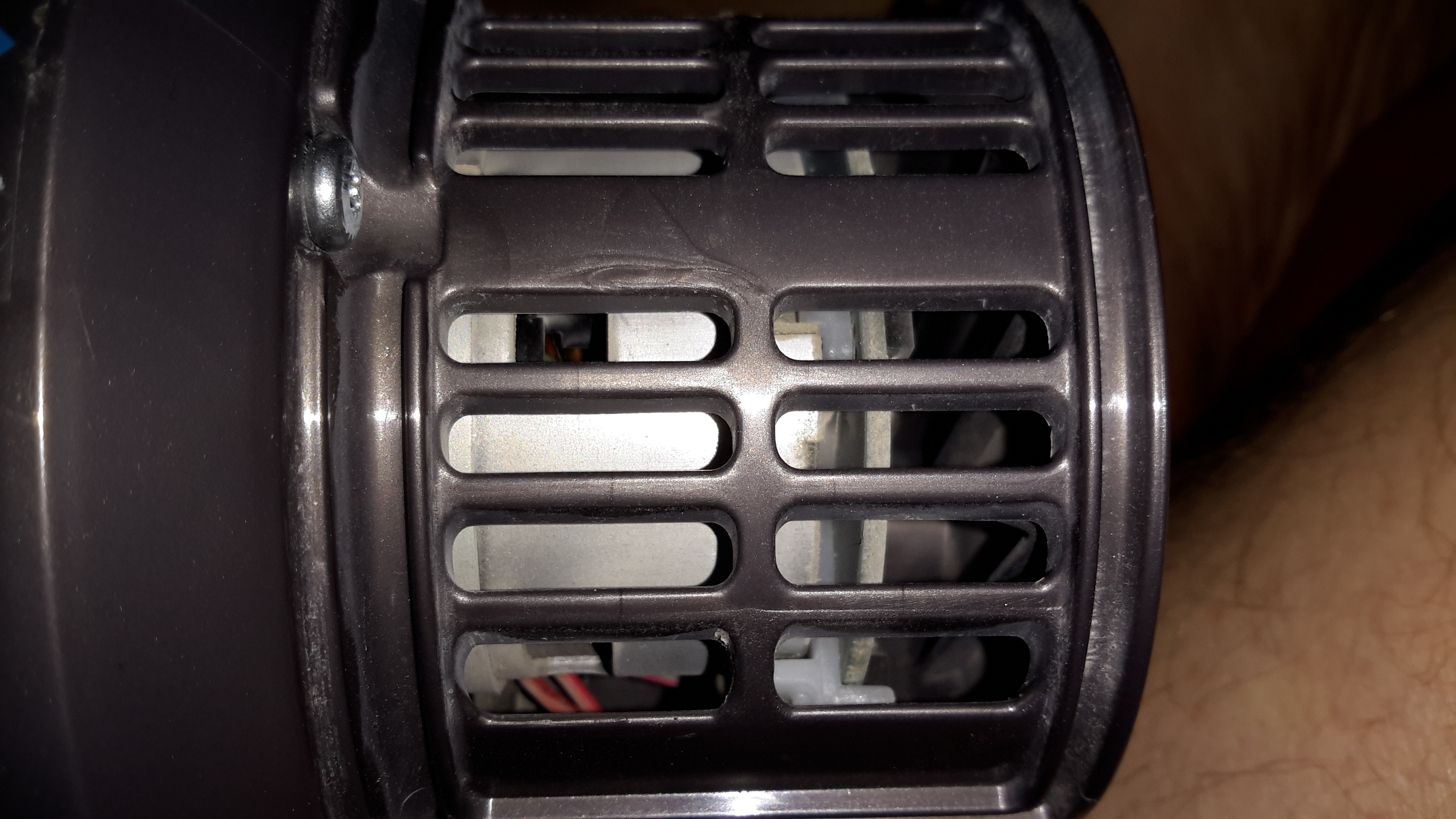
Motor
Hidden in the back side of the main body is the motor. Unfortunately I wasn’t able to get this out without doing some damage, as the wiring isn’t long enough to free the unit without some surgery.
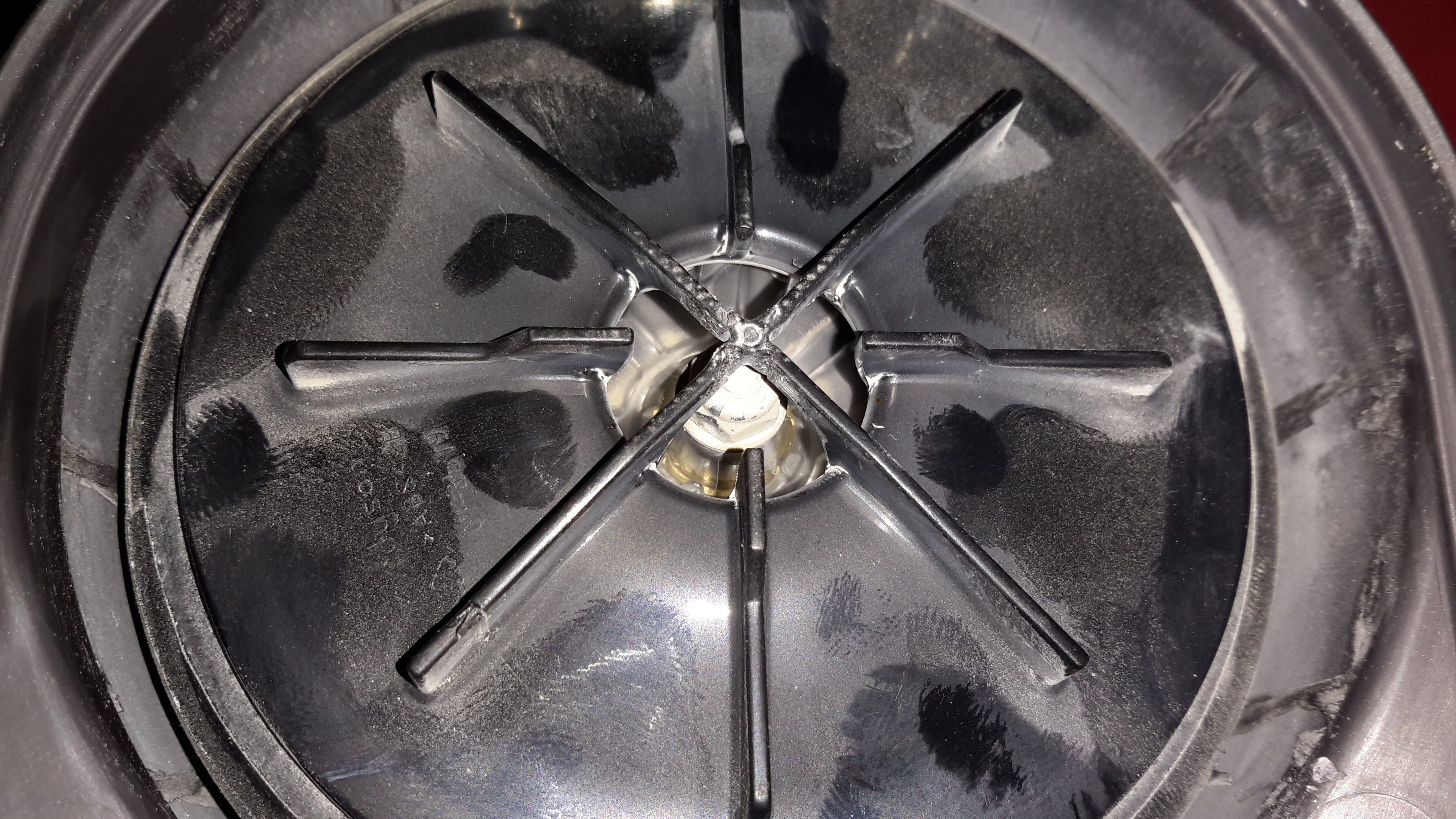
Turbine
The suction is generated by a smaller version of the centrifugal high-speed blowers used in full size vacuums. Not much to see here.
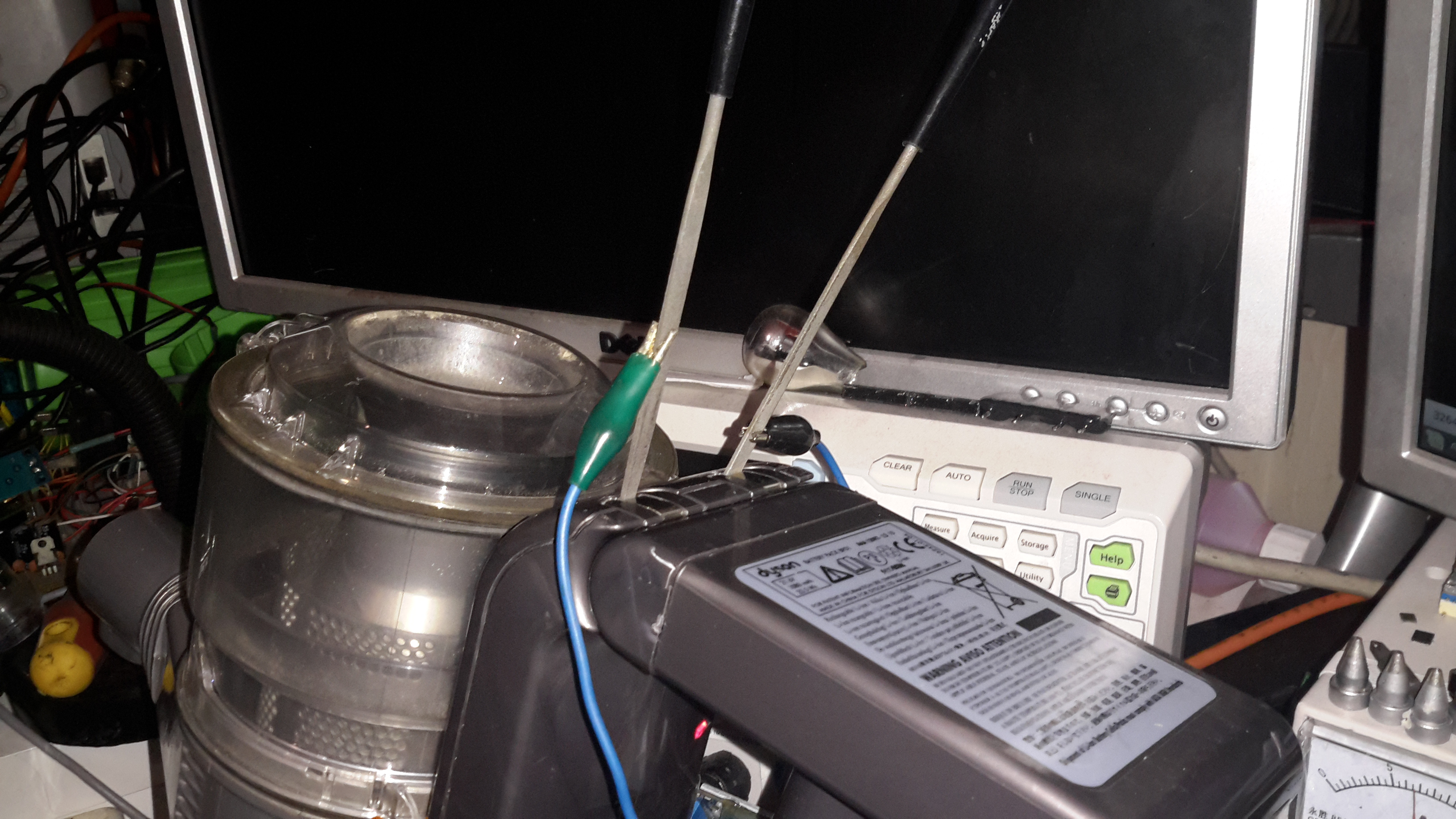
Unofficial Charger
Since I got this without a charger, I had to improvise. The factory power supply is just a 28v power brick, all the charging logic is in the vacuum itself, so I didn’t have to worry about such nasties as over-charging. I have since fitted the battery pack with a standard Li-Po balance cable, so it can be used with my ProCell charger, which will charge the pack in 35 minutes, instead of the 3 hours of the original charger.
I recently came across these on eBay, so I thought I’d grab one to see how they function, with all the metrics they display, there’s potential here for them to be very useful indeed.
One of the best parts is that no wiring is required between the sensor board & the LCD head unit – everything is transmitted over a 2.4GHz data link using NRF24L01 modules.
Above is the display unit, with it’s colour LCD display. Many features are available on this, & they appear to be designed for battery powered systems.
Monitor PCB
Another PCB handles the current & voltage sensing, so this one can be mounted as close to the high current wiring as possible.
Monitor PCB Microcontroller
The transmitter PCB is controlled with an STM8S003F3 microcontroller from ST Microelectronics. This is a Flash based STM with 8KB of ROM, 1KB of RAM & 10-bit ADC. The NRF24L01 transceiver module is just to the left.
There’s only a single button on this board, for pairing both ends of the link.
Output MOSFET
The high current end of the board has the 0.0025Ω current shunt & the output switch MOSFET, a STP75NF75 75v 75A FET, also from ST Microelectronics. A separate power source can be provided for the logic via the blue terminal block instead of powering from the source being measured.
LCD Unit Rear
Here’s the display unit, only a pair of power terminals are provided, 5-24v wide-range input is catered for.
LCD Unit PCB
Unclipping the back of the board reveals the PCB, with another 2.4GHz NRF24L01 module, and a STM8S005K6 microcontroller in this case. The switching power supply that handles the wide input voltage is along the top edge of the board.
Unfortunately I didn’t get any instruction manual with this, so some guesswork & translation of the finest Chinglish was required to get my head round the way everything works. To make life a little easier for others that might have this issue, here’s a list of functions & how to make them work.
LCD Closeup
On the right edge of the board is the function list, a quick press of the OK button turns a function ON/OFF, while holding it allows the threshold to be set.
When the output is disabled by one of the protection functions, turning that function OFF will immediately enable the output again.
The UP/DOWN buttons obviously function to select the desired function with the cursor just to the left of the labels. Less obviously though, pressing the UP button while the very top function is selected will change the Amp-Hours display to a battery capacity icon, while pressing DOWN while the very bottom function is selected will change the Watts display to Hours.
The round circle to the right displays the status of a function. Green for OK/ON Grey for FAULT/OFF.
OVP: Over voltage protection. This will turn off the load when the measured voltage exceeds the set threshold.
OPP: Over power protection. This function prevents a load from pulling more than a specified number of watts from the supply.
OCP: Over current protection. This one’s a little more obvious, it’ll disable the output when the current measured exceeds the specified limit.
OUT: This one is the status of the output MOSFET. Can also be used to manually enable/disable the output.
OFT: Over time protection. This one could be useful when charging batteries, if the output is enabled for longer than the specified time, the output will toggle off.
OAH: Over Amp-Hours protection. If the counted Amp-Hours exceeds the set limit, the output will be disabled.
Nom: This one indicates the status of the RF data link between the modules, and can be used to set the channel they operate on.
Pairing is achieved by holding the OK button, selecting the channel on the LCD unit, and then pressing the button on the transmitter board. After a few seconds, (it appears to scan through all addresses until it gets a response) the display will resume updating.
This function would be required if there are more than a single meter within RF range of each other.
I’ve not yet had a proper play with all the protection functions, but a quick mess with the OVP setting proved it was very over-sensitive. Setting the protection voltage to 15v triggered the protection with the measured voltage between 12.5v-13.8v. More experimentation is required here I think, but as I plan to just use these for power monitoring, I’ll most likely leave all the advanced functions disabled.
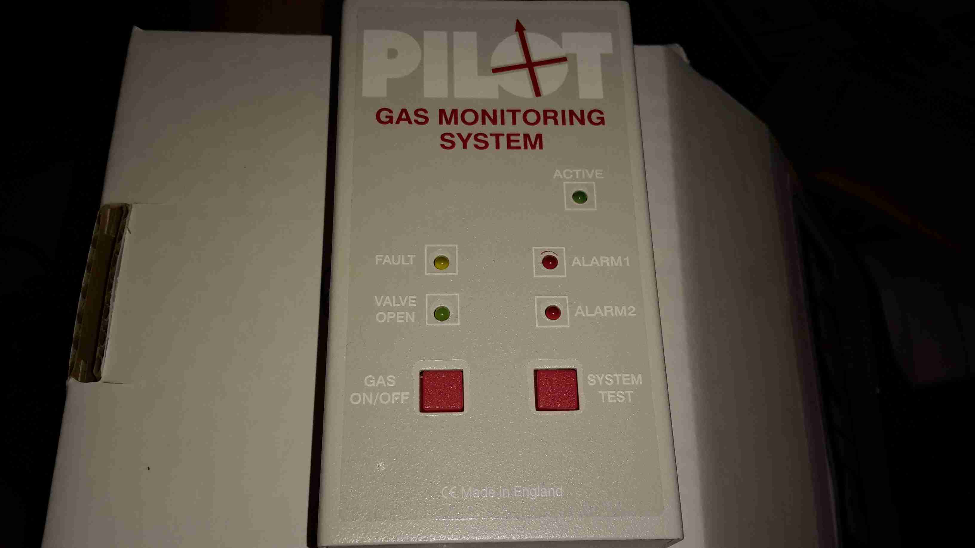
In my mind, the most dangerous thing onboard any boat is the LPG system, as the gas is heavier than air, any leaks tend to collect in the bilges, just waiting for an ignition source. To mitigate this possibility, we’re fitting a gas monitoring system that will sound an alarm & cut off the supply in case of a leak.
Monitor Unit
Here’s the monitor itself, the two sensor model. It’s nice & compact, and the alarm is loud enough to wake the dead.
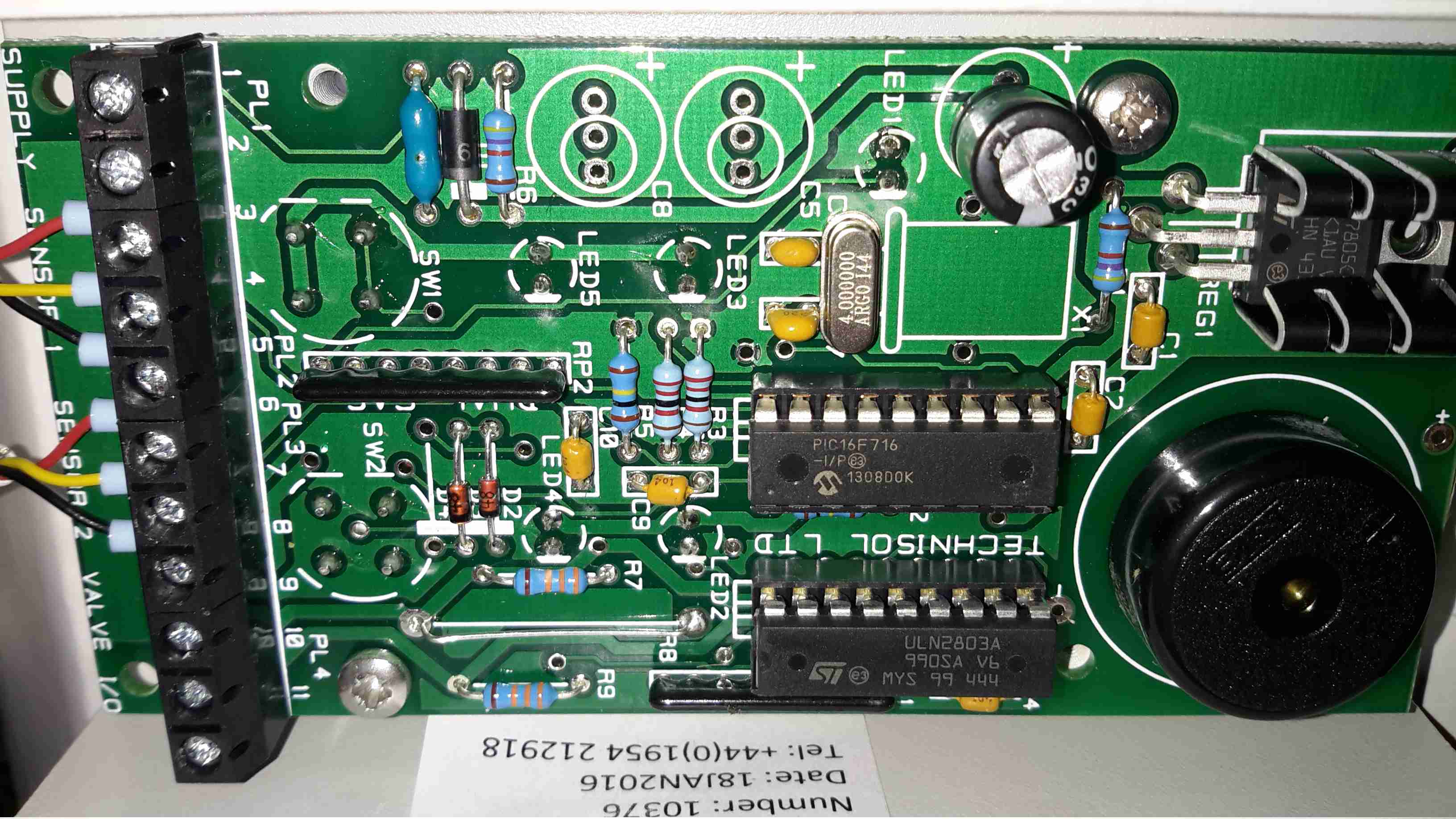
Control Board
Not much inside in the way of circuitry, the brains of the operation is a Microchip PIC16F716 8-bit microcontroller with an onboard A/D converter (needed to interface with the sensors), running at 4MHz. The solenoid valve is driven with a ULN2803 Darlington transistor array.
The alarm Piezo sounder can be seen to the right of the ICs, above that is a simple LM7805 linear regulator providing power to the electronics.
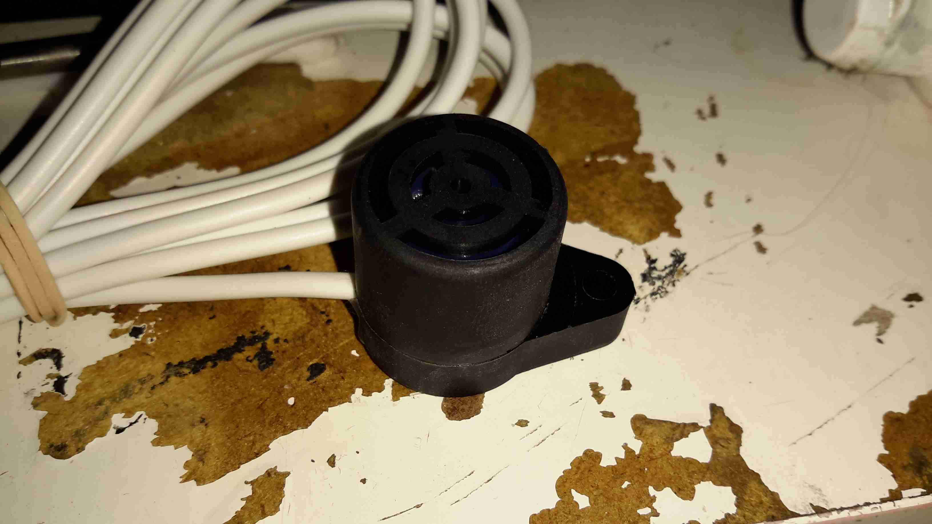
Remote Sensor
The pair of remote sensors come with 3.5m of cable, a good thing since the mounting points for these are going to be rather far from the main unit in our installation.
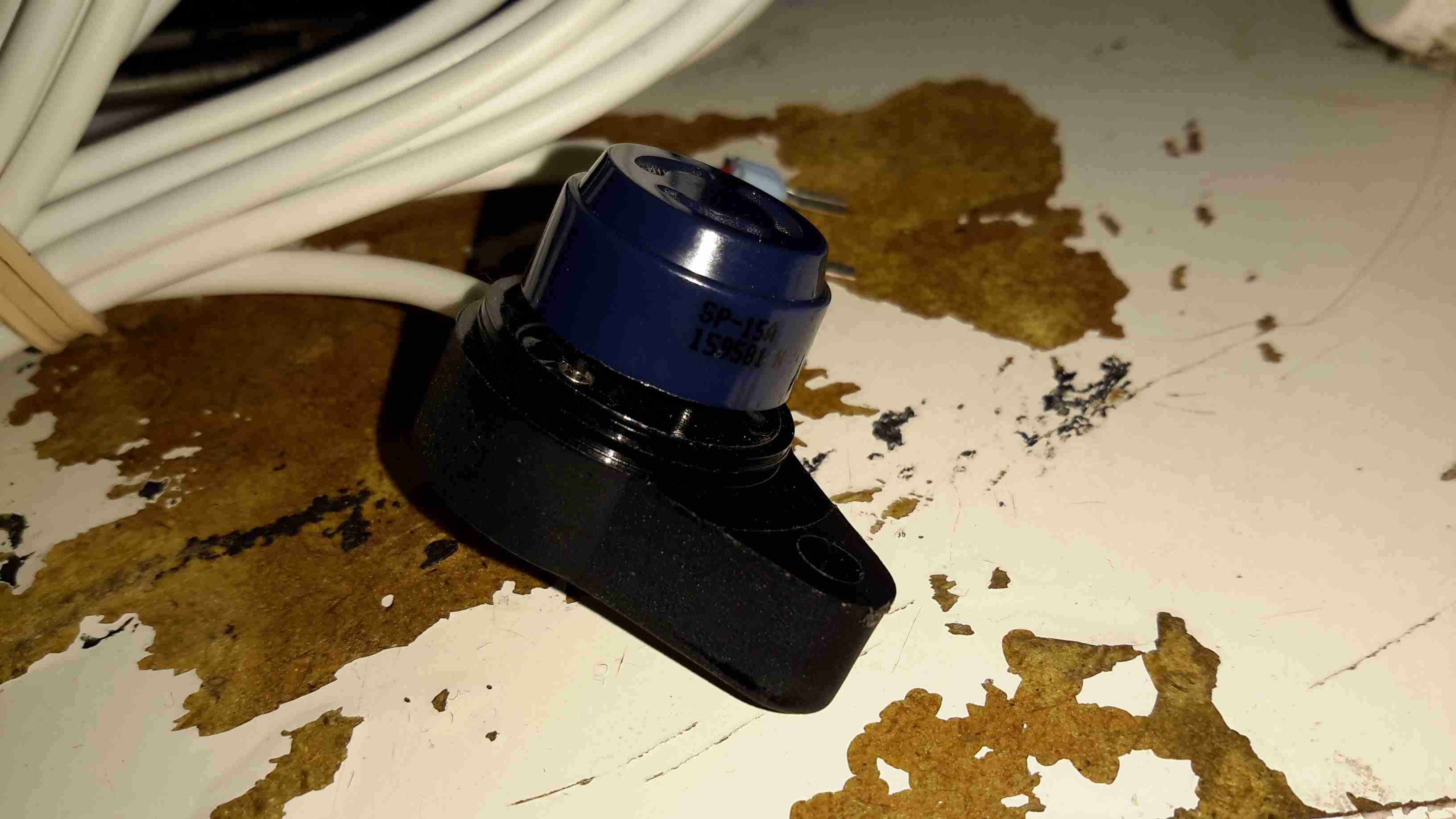
Sensor Element
The sensor itself is a SP-15A Tin Oxide semiconductor type, most sensitive to butane & propane. Unlike the Chinese El-Cheapo versions on eBay, these are high quality sensors. After whiffing some gas from a lighter at one of the sensors, the alarm triggered instantly & tripped the solenoid off.
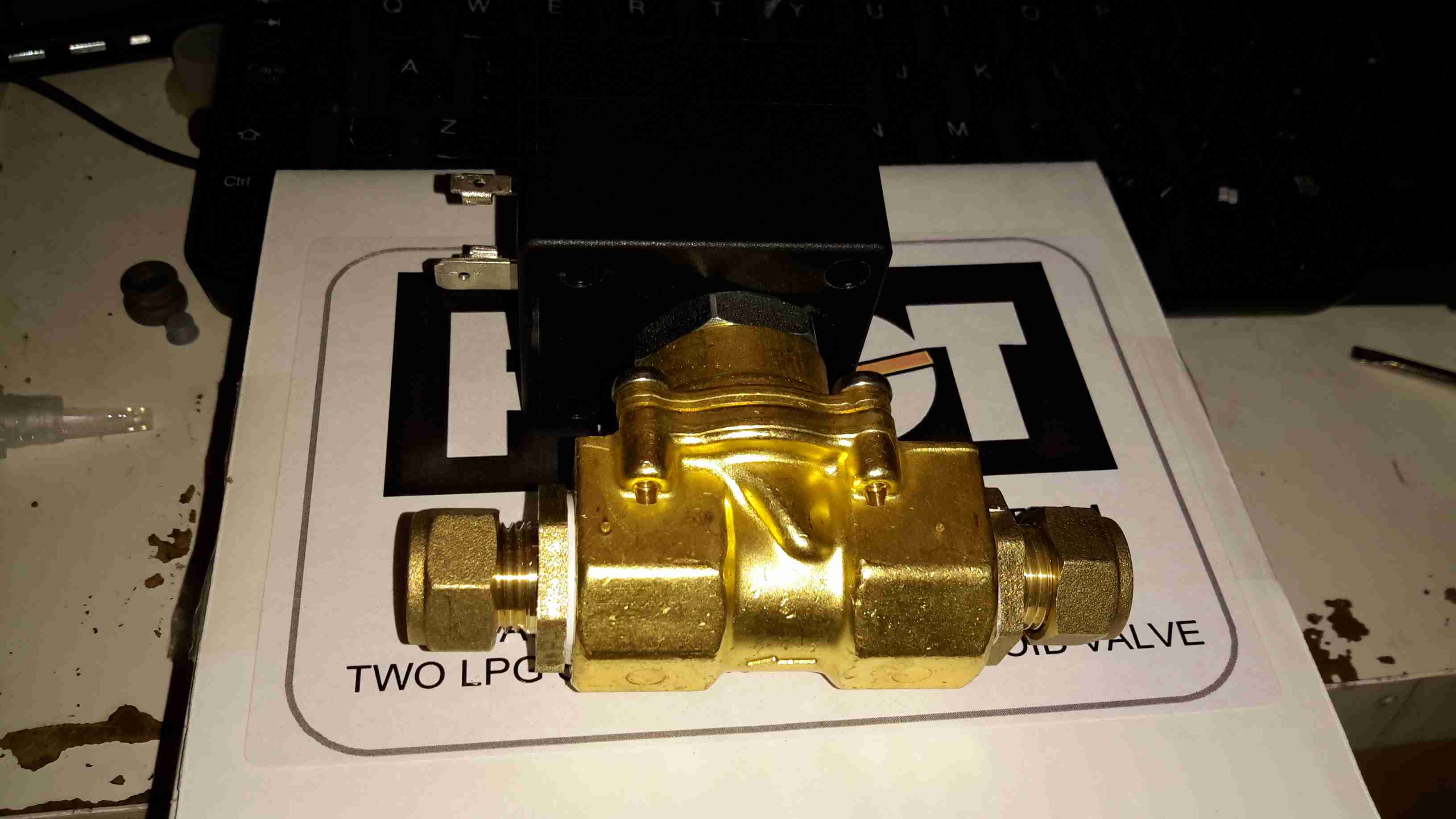
Solenoid Valve
The solenoid valve goes into the gas supply line after the bottle regulator, in this case I’ve already fitted the adaptors to take the 10mm gas line to the 1/2″ BSP threads on the valve itself. This brass lump is a bit heavy, so support will be needed to prevent vibration compromising the gas line.
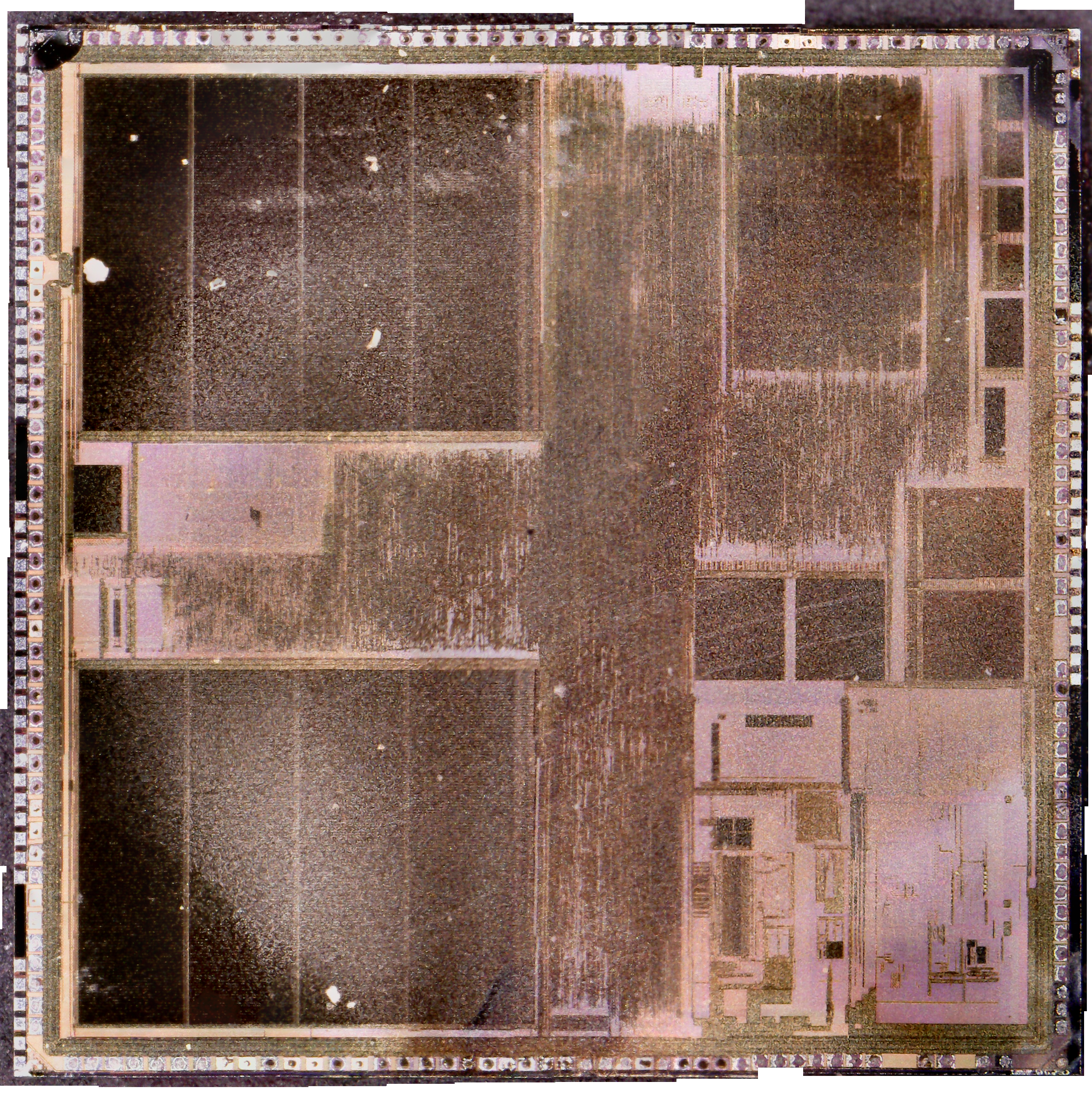
I’ve been working on something new for the blog, as I have a massive collection of scrap ICs – that is to decap the silicon & get them under a microscope!
Here’s the first image, a Texas Instruments part. This has been stitched together from 140 separate images to create the final version.
TI-Chip
Tip Jar
If you’ve found my content useful, please consider leaving a donation by clicking the Tip Jar below!
All collected funds go towards new content & the costs of keeping the server online.