Posted on Leave a comment

Rigol DS1054Z 12v Power Supply Project – Completion

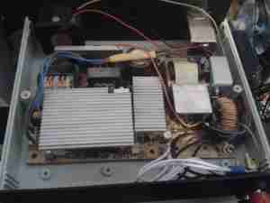
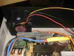
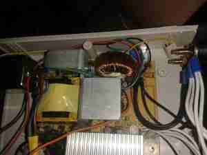
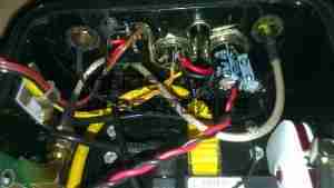
All of the parts I required to complete the supply arrived this morning. After several hours of building, here’s what I came up with:

12v Power Supply
12v Power Supply

I’ve mounted everything on a piece of FR4 PCB, with it’s copper plane grounded to the case. This backing board is the same size as the original PSU PCB to allow it to be screwed into the same location in the scope.

The power comes in via the converter on the right, which outputs a single 24v rail for the rest of the supplies. The other 6 supplies then generate the individual voltage rails that the scope requires. The use of a single input supply allows this system to operate at voltages up to 30v DC, so it’s good for both 12v & 24v systems.

Scope Ripple
Scope Ripple

At present the only issue is with some ripple on one of the supplies, this is showing up on the scope display with no input connected at the lowest volts/division. Parts are on order from Farnell to build some common mode filters to remove this from the DC output.

On a 13.8v supply, the scope draws about 1.5A total from the supply, giving a total power consumption of 20.7W. This is with all 4 channels enabled.

My wiring assignments & DC-DC converter ratings are in the table below

Connector PinPCB PinSignalMainboardDC-DC RatingWire Colour
110GNDGNDN/ABLACK
22+9v_GNDFAN --NABLACK
38+7.5V6.3V6AORANGE
414-7.5V-7.5V2AGREEN
51NOT USEDAC_TRIGN/ANOT USED
64+5V5V5A6ARED
76GNDGNDN/ABLACK
87GNDGNDN/ABLACK
912-17.5V-17.5V3APURPLE
109+7.5V6.3V6AORANGE
113+9VFAN +1AGREY
121117.5V17.5V3ABLUE
135+5V5V5A6ARED
1413GNDGNDN/ABLACK

Stay tuned for the final section of this build with the power supply filtering & main DC input connections!

73s for now 🙂

Posted on Leave a comment

12v CFL Lamp Failure Analysis

On the boat I have installed custom LED lighting almost everywhere, but we still use CFL bulbs in a standing lamp since they have a wide light angle, and brightness for the size.

I bought a couple of 12v CFLs from China, and the first of these has been running for over a year pretty much constantly without issue. However, recently it stopped working altogether.

12v CFL
12v CFL

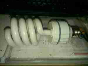
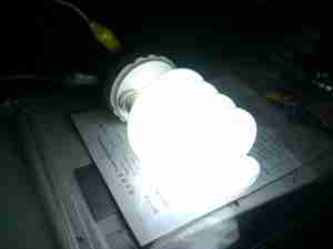
Here’s the lamp, exactly the same as the 240v mains versions, except for the design of the electronic ballast in the base. As can be seen here, the heat from the ballast has degraded the plastic of the base & it’s cracked. The tube itself is still perfectly fine, there are no dark spots around the ends caused by the electrodes sputtering over time.

Ballast
Ballast

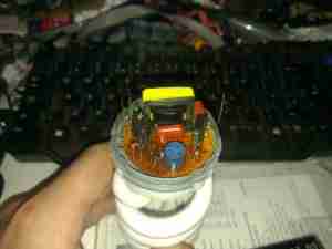
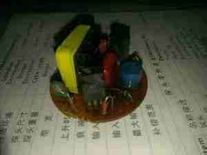
Here’s the ballast inside the bottom of the lamp, a simple 2-transistor oscillator & transformer. The board has obviously got a bit warm, it’s very discoloured!

Failed Wiring
Failed Wiring

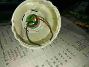
The failure mode in this case was cooked wiring to the screw base. The insulation is completely crispy!

Direct Supply
Direct Supply

On connection direct to a 12v supply, the lamp pops into life again! Current draw at 13.8v is 1.5A, giving a power consumption of 20.7W. Most of this energy is obviously being dissipated as heat in the ballast & the tube itself.

Ballast PCB
Ballast PCB

Here’s the ballast PCB removed from the case. It’s been getting very warm indeed, and the series capacitor on the left has actually cracked! It’s supposed to be 2.2nF, but it reads a bit high at 3nF. It’s a good thing there are no electrolytics in this unit, as they would have exploded long ago. There’s a choke on the DC input, probably to stop RFI, but it doesn’t have much effect.

Supply Waveform
Supply Waveform

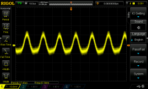
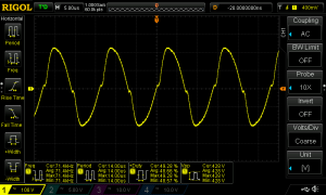
Here’s the waveform coming from the supply, a pretty crusty sinewave at 71.4kHz. The voltage at the tube is much higher than I expected while running, at 428v.

RFI
RFI

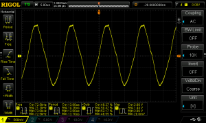
Holding the scope probe a good 12″ away from the running bulb produces this trace, which is being emitted as RFI. There’s virtually no filtering or shielding in this bulb so this is inevitable.

Posted on Leave a comment

Chinese Power Supply Update

Having now tested the supply I wrote about in my previous post, I can now say that it’s nameplate rating far exceeds it’s actual capability.

On running the supply under load, at 6.5A the operating frequency drops into the audible range, a big sign of overload. (It makes an irritating continuous chirping noise). The output voltage also drops to 10.5v.

The temperature of the unit while it’s been running under such a load is also questionable, the external casing gets hot enough to cause burns, I haven’t yet been able to stick a thermocouple into the case to see what the internal temperature is.

I’m currently talking with the eBay seller (wwwstation) regarding this, however they are arguing that the supply is only for LEDs & CCTV cameras.
However those two loads are very different, and the supply has no internal regulation for supplying LEDs. As a simple switchmode supply, any load is suitable, providing it’s within the load rating of the supply.
I would estimate that the supply is only capable of 5A as an upper limit.

They are requesting that I return the supply, but I’m yet to find out if they’re going to cover return postage. The item as listed is not as described, and I will escalate things if required.
I will update this post when I hear more back from the eBay seller.

73s for now 🙂

Posted on Leave a comment

13.8v SMPS PSU Final Additions

Following on from my recent power supply build, I’ve added on a couple of improvements:

Front Panel
Front Panel

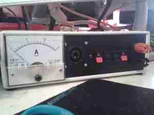
I’ve added on my standard SpeakOn type 30A connector, a bank of push terminals for quick connecting test leads, and a 15A FSD ammeter.

Panel Rear
Panel Rear

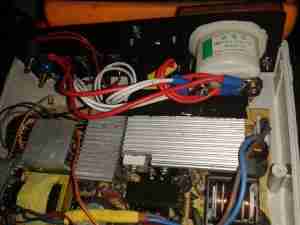
Due to the limited space inside the supply, I’ve had to improvise some insulation on the mains-side heatsink to prevent a nasty accident. The heatsinks are tied to the supply’s HVDC bus negative, so they are energized at -145v DC relative to mains earth. This fact has given me a nasty surprise! The insulation is several layers of Kapton tape, with a couple of layers of Duct Tape. This along with trirated wire to the SpeakOn & the panel meter should ensure safety.

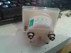
The Ammeter itself was sourced from eBay, for £2. It seems pretty accurate so far!

Ammeter
Ammeter

The shunt is built into the rear of these meters, in an ultrasonically welded part of the case, so I can’t examine it. Hopefully it is indeed rated to 15A!

The only things left to make this supply complete are a mains power switch, and a fan speed control, as the fan I have used is a little noisy at full speed. It will be good to get the speed based from the internal temperature, so the fan only runs at full speed when the supply is under load.


Posted on Leave a comment

13.8v SMPS PSU Build

A while ago I blogged about modifying the output voltage of some surplus Cisco switch power supplies to operate at 13.8v.

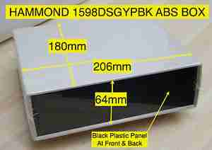
Since I was able to score a nice Hammond 1598DSGYPBK ABS project box on eBay, I’ve built one of the supplies into a nice bench unit.

Hammond ABS Case
Hammond ABS Case
Supply Unit
Supply Unit

Above is the supply mounted into the box, I had to slightly trim one edge of the PCB to make everything fit, as it was just a couple of mm too wide. Luckily on the mains side of the board is some space without any copper tracks.

PSU Fan
PSU Fan

These supplies are very high quality & very efficient, however they came from equipment that was force-air cooled. Running the PSU in this box with no cooling resulted in overheating. Because of this I have added a small 12v fan to move some air through the case. The unit runs much cooler now. To allow the air to flow straight through the case, I drilled a row of holes under the front edge as vents.

Output Side
Output Side

Here is the output side of the supply, it uses standard banana jacks for the terminals. I have used crimp terminals here, but they are soldered on instead of crimped to allow for higher current draw. The negative return side of the output is mains earth referenced.

I have tried to measure output ripple on this supply, but with my 10X scope probe, and the scope set to 5mV/Div, the trace barely moves. The output is a very nice & stable DC.

This supply is now running my main radio in the shack, and is small enough to be easily portable when I move my station.

Posted on Leave a comment

QSO Logging Systems

As per my site update post, I have migrated my radio log onto a new system, from CQRLOG.

CQR log has served me well since I first started in Amateur Radio, however it’s a bit complex to use, requires a backend MySQL server for it’s database, and as it’s a local application, it’s not possible to share my log with other Hams without some difficulty.
The only other major system with an online logging system is QRZ, and I find that particular site a bit of a pain, and many of the features there aren’t free. (Although it’s not horrendously expensive, I’m on a very tight budget & I must save where I can).

CQRLOG
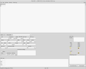
CQRLOG Screenshot

Because of these points, I went on a search for something that would better serve my needs. I have discovered during this search that there’s liitle out there in the self-hosted respect.

I did however find Cloudlog, a web based logging system in PHP & MySQL.
This new system allows integration with the main site, as I can run it on the same server & LAMP stack, it’s very simple to use, is visually pleasing and it even generates a Google Map view of recent QSO locations.
It will also allow me to save some resources on my main PC, running a full-blown MySQL server in the background just for a single application is resource intensive, and a bit of a waste of CPU cycles. (CQRLOG and it’s associated MySQL server is 300MB of disk space, CloudLog is 27MB).

Backups are made simpler with this system also, as it’s running on my core systems, incremental backups are taken every 3 hours, with a full system backup every 24 hours. Combined with offsite backup sync, data loss is very unlikely in any event. All this is completely automatic.
I can also take an ADIF file from Cloudlog for use with any other logging application, if the need arises.

Cloudlog is built & maintained by Peter Goodhall, 2E0SQL.
From the looks of Github, there’s also a version 2 in development, although now I have version 1 up & running, I might just stick with it, unless an easy upgrade path is available.

When I am not operating mobile, new QSOs should appear in this system almost immediately, with their respective pins on the map. (These are generated by the Grid Square location, so accuracy may vary).
If you’ve spoken to me on the air & I haven’t updated it, I’m most likely away from an internet connection, in which case your callsign will appear as soon as I have access.

73s for now folks!

Posted on Leave a comment

Abuse On GB3MR

GB3MR currently has a big issue with a couple of pirates blocking use of the repeater, and while I’ve not heard anything from them in a few days, today has been much different.
I didn’t manage to get a full recording in this instance, but here’s some of the interference that’s being transmitted. In this case it sounds like there’s a licensed station or two trying to break through but not getting very far. (Sure I heard a callsign or two in there somewhere, whether they’re valid is another thing). Happy listening 🙂

 Luckily it’s not difficult to obliterate the pirate signal when a valid QSO is in progress, and it’s not much of an inconvenience. They must be using a wet piece of string to get such a bad signal in 😉

Posted on Leave a comment

Some Site Changes

After a few years of running with the same look, I’ve decided on some changes.

  • New theme!
    The site now looks much better, and has better support for more eye candy 😉
  • Addition of my QRZ link
  • New QSO logging system
    Accessible from a button in the header, this is my new preferred system for logging my radio contacts. (I was originally using CQRLOG under Linux). If I’ve spoken to you on the radio your callsign will most likely appear immediately. 🙂
    If not, I’m probably working mobile. In that case, drop me a comment or an E-Mail 🙂

Finally there have been some behind the scenes changes to implement some better security on site.
Getting the number of hits I do per day, this site gets attacked by the Internet’s Great Unwashed on a regular basis. No attack has ever been successful but more security never hurts!

73s folks!

Posted on 22 Comments

GY561 Frequency & Power Meter

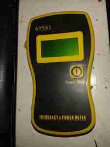
The latest addition to my radio shack is the GY561 frequency & power meter, which has already come in useful for measuring the output power of all my radios.

GY561
GY561

It’s a small device, roughly the same size & weight as a stock UV-5R. Power is provided by 3 AAA cells.

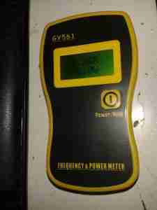
Display
Display

The display is a standard HD44780 8×2 module. The display on this unit isn’t backlit, so no operating in the dark.

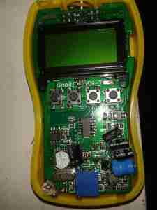
Cover Removed
Cover Removed

The cover pops off easily to allow access to the internals, without having to remove any screws!
The 4 screws on the back of the unit hold the heatsink plate for the 50W 50Ω dummy load resistor.
Removing the cover reveals a couple of adjustments, for frequency & RF power calibration.

There are also 3 tactile switches that aren’t on the front panel. According to the manual (which in itself is a masterpiece of Chinglish), they are used to software calibrate the unit if an accurate RF power source is available. I will attempt to do a reasonable translation when time allows.

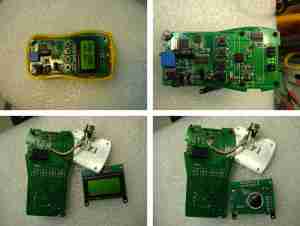
Disassembly further than this involves some desoldering in awkward places, so a search of the internet revealed an image of the rest of the internal components. In the case of my meter, all the part numbers have been scrubbed off the ICs in an attempt to hide their purpose. While it’s possible to cross-reference IC databooks & find the part numbers manually, this process is a time consuming one. Luckily the image I managed to locate doesn’t have the numbers scrubbed.

Total Disassembly
Total Disassembly

Under the LCD is some 74HC series logic, and a prescaler IC as seen in the previous frequency counter post. However in this unit the prescaler is a MB506 microwave band version to handle the higher frequencies specified.
In this case however the main microcontroller is an ATMEGA8L.
This is complemented by a SN54HC393 4-bit binary counter for the frequency side of things. This seems to make it much more usable down to lower frequencies, although the manual is very generous in this regard, stating that it’s capable of reading down to 1kHz. In practice I’ve found the lowest it reliably reads the frequency input is 10MHz, using my AD9850 DDS VFO Module as a signal source.
It did however read slightly high on all readings with the DDS, but this could have been due to the low power output of the frequency source.
Just like the other frequency counter module, this also uses a trimmer capacitor to adjust the microcontroller’s clock frequency to adjust the calibration.

The power supply circuitry is in the bottom left corner of the board, in this case a small switching supply. The switching regulator is needed to boost the +4.5v of the batteries to +5v for the logic.
Also, as the batteries discharge & their terminal voltage drops, the switching regulator will allow the circuit to carry on functioning. At present I am unsure of the lower battery voltage limit on the meter, but AAA cells are usually considered dead at 0.8v terminal voltage. (2.4v total for the 3 cells).
When turned on this meter draws 52mA from the battery, and assuming 1200mAh capacity for a decent brand-name AAA cell, this should give a battery life of 23 hours continuous use.

On the back of the main PCB is a 5v relay, which seems to be switching an input attenuator for higher power levels, although I only managed to trigger it on the 2m band.

Finally, right at the back attached to an aluminium plate, is the 50Ω dummy load resistor. This component will make up most of the cost of building these, at roughly £15.

On my DVM, this termination reads at about 46Ω, because of the other components on the board are skewing the reading. There are a pair of SMT resistors, at 200Ω & 390Ω in series, and these are connected across the 50Ω RF resistor, giving a total resistance of 46.094Ω.
This isn’t ideal, and the impedance mismatch will probably affect the calibration of the unit somewhat.

The heatsinking provided by the aluminium plate is minimal, and the unit gets noticeably warm within a couple of minutes measuring higher power levels.
High power readings should definitely be limited to very short periods, to prevent overheating.
The RF is sampled from the dummy load with a short piece of Teflon coax.

There’s a rubber duck antenna included, but this is pretty useless unless it’s almost in contact with the transmitting antenna, as there’s no input amplification. It might be handy for detecting RF emissions from power supplies, etc.

For the total cost involved I’m not expecting miracles as far as accuracy is concerned, (the manual states +/-10% on power readings).
The frequency readout does seem to be pretty much spot on though, and the ability to calibrate against a known source is handy if I need some more accuracy in the future.

I’ve also done an SWR test on the dummy load, and the results aren’t good.

At 145.500 MHz, the SWR is 3:1, while at 433.500 it’s closer to 4:1. This is probably due to the lower than 50Ω I measured at the meter’s connector.
These SWR readings also wander around somewhat as the load resistor warms up under power.

I’ll probably also replace the AAA cells with a LiPo cell & associated charge/protection circuitry, to make the unit chargeable via USB. Avoiding disposable batteries is the goal.

Posted on 1 Comment

Cisco PSU Hack & Switched Mode PSU Background

Recently I decommissioned some networking equipment, and discovered the power supplies in some switches were single rail 12v types, with a rather high power rating. I figured these would be very good for powering my Ham radio gear.

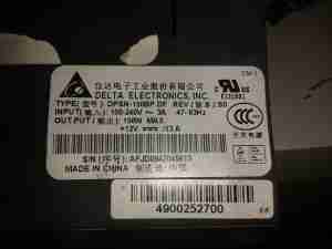
They’re high quality Delta Electronics DPSN-150BP units, rated at a maximum power output of 156W.

Label
Label

These supplies have an adjustment pot for the output voltage regulation, but unfortunately it just didn’t have quite enough range to get from 12.0v to 13.8v. The highest they would go was ~13.04v.

After taking a look at the regulator circuit, I discovered  I could further adjust the output voltage by changing a single resistor to a slightly lower value.

Firstly though, a little background on how switched mode power supplies operate & regulate their output voltage.

SMPS
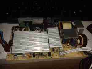
SMPS

Here’s the supply. It’s mostly heatsink, to cool the large power switching transistors.

The first thing a SMPS does, is to rectify the incoming mains AC with a bridge rectifier. This is then smoothed by a large electrolytic capacitor, to provide a main DC rail of +340v DC (when on a 240v AC supply).

Mains Input
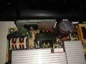
Mains Input

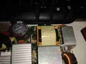
Above is the mains input section of the PSU, with a large common-mode choke on the left, bridge rectifier in the centre, and the large filter capacitor on the right. These can store a lot of energy when disconnected from the mains, and while they should have a discharge resistor fitted to safely drain the stored energy, they aren’t to be relied on for safety!

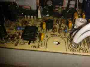
Once the supply has it’s main high voltage DC rail, this is switched into the main transformer by a pair of very large transistors – these are hidden from view on the large silver heatsinks at the bottom of the image. These transistors are themselves driven with a control IC, in the case of this supply, it’s a UC3844B. This IC is hidden under the large heatsink, but is just visible in the below photo. (IC5).

Control IC
Control IC
Main Switching Transformer

Here’s the main switching transformer, these can be much smaller than a conventional transformer due to the high frequencies used. This supply operates at 500kHz.
After the main transformer, the output is rectified by a pair of Schottky diodes, which are attached to the smaller heatsink visible below the transformer, before being fed through a large toroidal inductor & the output filter capacitors.
All this filtering on both the input & the output is required to stop these supplies from radiating their operating frequency as RF – a lot of cheap Chinese switching supplies forego this filtering & as a result are extremely noisy.

After all this filtering the DC appears at the output as usable power.

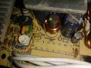
Getting back to regulation, these supplies read the voltage with a resistor divider & feed it back to the mains side control IC, through an opto-isolator. (Below).

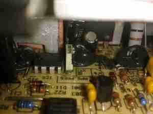
Feedback Loop
Feedback Loop

The opto isolators are the black devices at the front with 4 pins.

Regulator Adjustment

For a more in-depth look at the inner workings of SMPS units, there’s a good article over on Hardware Secrets.

My modification is simple. Replacing R306 (just below the white potentiometer in the photo), with a slightly smaller resistor value, of 2.2KΩ down from 2.37KΩ, allows the voltage to be pulled lower on the regulator. This fools the unit into applying more drive to the main transformer, and the output voltage rises.

It’s important to note that making too drastic a change to these supplies is likely to result in the output filter capacitors turning into grenades due to overvoltage. The very small change in value only allows the voltage to rise to 13.95v max on the adjuster. This is well within the rating of 16v on the output caps.

Now the voltage has been sucessfully modified, a new case is on the way to shield fingers from the mains. With the addition of a couple of panel meters & output terminals, these supplies will make great additions to my shack.

More to come on the final build soon!

Posted on Leave a comment

uRadMonitor – Node Online!

It’s official. I’m now part of the uRadMonitor network, & assisting in some of the current issues with networking some people (including myself) have been having.

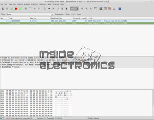
It seems that the uRadMonitor isn’t sending out technically-valid DHCP requests, here is what Wireshark thinks of the DHCP on my production network hardware setup:

WireShark Screencap
WireShark Screencap

As can be seen, the monitor unit is sending a DHCP request of 319 bytes, where a standard length DHCP Request packet should be ~324 bytes, as can be seen on the below screen capture.

Valid DHCP
Valid DHCP

This valid one was generated from the same SPI Ethernet module as the monitor, (Microchip ENC28J60) connected to an Arduino. Standard example code from the EtherCard library was used to set up the DHCP. The MAC address of the monitor was also cloned to this setup to rule out the possibility of that being the root cause.

My deductive reasoning in this case points to the firmware on the monitor being at fault, rather than the SPI ethernet hardware, or my network hardware. Radu over at uRadMonitor is looking into the firmware being at fault.

Strangely, most routers don’t seem to have an issue with the monitor, as connecting another router on a separate subnet works fine, and Wireshark doesn’t even complain about an invalid DHCP packet, although it’s exactly the same.

Working DHCP
Working DHCP

As the firmware for the devices isn’t currently available for me to pick apart & see if I can find the fault, it’s up to Radu to get this fixed at the moment.

Now, for a µTeardown:

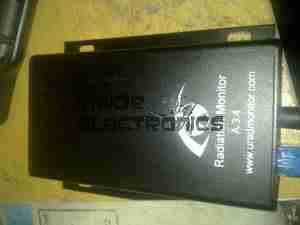
uRadMonitor
uRadMonitor

Here is the monitor, a small aluminium box, with power & network.

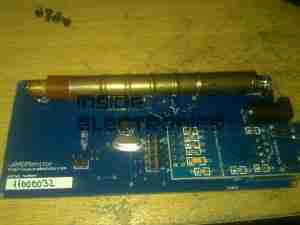
PCB
PCB

Removing 4 screws in the end plate reveals the PCB, with the Geiger-Mueller tube along the top edge. My personal serial number is also on the PCB.
The ethernet module is on the right, with the DC barrel jack.

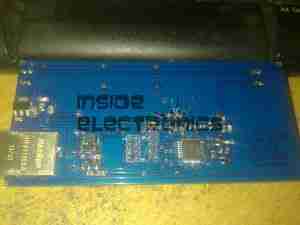
PCB Bottom
PCB Bottom

Here is the bottom of the PCB, with the control MCU & the tiny high voltage inverter for the Geiger tube.

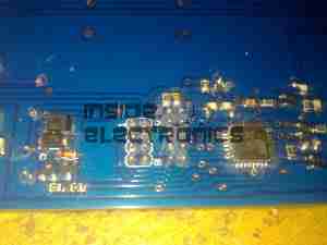
Control Electronics
Control Electronics

A Closeup of the main MCU, an ATMega328p

Logo
Logo

PCB Logo. Very artsy 😉

Posted on Leave a comment

Lying Again Are We? (Mike Webb Of Hydraulicgenerators.co.uk)

Regular readers might remember a previous post about the fiasco we have had with a hydraulic generator, and in particular one person by the name of Mike Webb.

Well here we are a year down the line. The generator still doesn’t function properly, as other things have taken priority, but this is being remedied this week with a replacement hydraulic powerhead. (Correctly sized to 6cc this time, not 11cc).

I even finally got a response from Mike, most likely due to my previous post & the negative publicity that would have brought. In July Mike wrote this:

Good Morning Ben,


I have read your article on the above website, not entirely sure what I can say.


I do however sincerely apologise for the way I handled things, I could give numerous reasons, but I guess they are not your concern, I behaved badly and I am disappointed in myself for treating anyone in this way.


The business has now folded, the domain name www.hydraulicgenerators.co.uk and related products are now owned, manufactured and sold by another company.


My only hope now is that I can in some way repair the damage that has been done and hope that somewhere within yourself you can find a way to accept my apology and forgive me, I am genuinely not a bad person but circumstances outside of my control at the time led me to act in an inacceptable way.


I can understand how you feel, I was defrauded out of a considerable amount of money a while ago and seeking revenge has not been far from my mind for a considerable time, but it won’t get my money back, it won’t undo the damage that has already been done and whilst I might feel better about it for a short while, I have found it difficult from a personal perspective, as, whilst you may cast aspersions about me, my conscience and I do have one just won’t allow me, I can’t help myself from thinking of the other people that would be impacted upon that are otherwise innocent and I know in this particular instance there are several.


I can only hope that you accept my most sincere apology.

Right then. Where should I begin.

No Mike, I will never EVER forgive someone for, what was in my eyes, a deliberate act of fraud & a complete refusal to co-operate.

Now, being the resourceful person I am, and my ability (like anyone else with brains), to find out the registrar of domain names, have discovered the man is yet again lying. Company folded? I think not my son.

Two other domain names have popped up with Mike’s name on the Registrar details:
ukgenerators.co.uk
shop4generators.co.uk

(For completeness, here are the full registrar details, just in case things change after I publish this. This information is correct as of 9/12/14)

Domain name:
        ukgenerators.co.uk

    Registrant:
        Mike Webb

    Registrant type:
        UK Individual

    Registrant’s address:
 <REDACTED>

    Data validation:
        Registrant contact details validated by Nominet on 10-Dec-2012

    Registrar:
        LCN.com Ltd [Tag = LCN]
        URL: http://www.lcn.com

    Relevant dates:
        Registered on: 06-Feb-2004
        Expiry date:  06-Feb-2016
        Last updated:  16-Jan-2014

    Registration status:
        Registered until expiry date.

    Name servers:
        ns1.hostpapa.com
        ns2.hostpapa.com

    WHOIS lookup made at 16:56:14 09-Dec-2014

    Domain name:
        shop4generators.co.uk

    Registrant:
        Mike Webb

    Registrant type:
        UK Individual

    Registrant’s address:
        The registrant is a non-trading individual who has opted to have their
        address omitted from the WHOIS service.

    Data validation:
        Registrant contact details validated by Nominet on 10-Dec-2012

    Registrar:
        Webfusion Ltd t/a 123-reg [Tag = 123-REG]
        URL: http://www.123-reg.co.uk

    Relevant dates:
        Registered on: 02-Jun-2005
        Expiry date:  02-Jun-2015
        Last updated:  27-Jun-2013

    Registration status:
        Registered until expiry date.

    Name servers:
        ns1.hostpapa.com
        ns2.hostpapa.com

    WHOIS lookup made at 16:55:43 09-Dec-2014


Now for someone who is obviously attempting to tell me that he has no money or resources to reimburse us for the utter hell we have been put through in this situation, seems to be doing pretty well for themselves, in the same business that has apparently ‘folded’.
You have a shiny new logo & business name, and yet apparently have ceased trading?
Now, having been part of a firm during a takeover/company sale, domain names are usually immediately transferred into the name of the buying company. Not in this case it seems. All domains are still registered to you.
Your LinkedIn account still has you as being in the business, along with your Twitter account & YouTube account.
Not to mention, that one one of the aforementioned sites (the original hydraulicgenerators.co.uk), Mike’s E-Mail address is still very much visible on the front page E-Mail Link!

Despite all this evidence of continued trading, according to Companies House, the company is in fact in liquidation: http://data.companieshouse.gov.uk/doc/company/06770818

If this is the case, then Mike Webb is in fact operating illegally.

Mike, if you do read this, I AM NOT AN IDIOT. All I asked was that you put things right, so we would have a WORKING GENERATOR.
So far all this has cost is time & money, and I certainly don’t like being conned.
However I feel it is my duty to make sure that anyone who ever has the misfortune of dealing with you knows exactly what you have previous form for doing.

Legal notice:
All information contained in this post is correct as of 9/12/14. Information will be kept up to date & factually correct to the best of my ability.

Stay tuned for the final chapter in getting this generator fitted & working.
Posted on Leave a comment

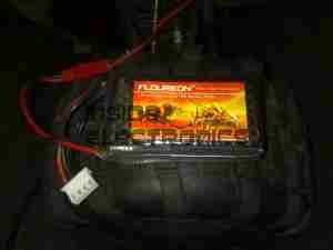
HPI Savage X 4.6 LiPo Receiver Battery

3S Lithium-Polymer Pack

To provide more run time with the conversion to petrol & spark ignition, I have also upgraded the on-board electronics supply to compensate for the extra ~650mA draw of the ignition module.
This modification is centred around a 3S Lithium-Polymer battery pack, providing a nominal 11.1v to a voltage regulator, which steps down this higher voltage to the ~6v required by the receiver & servo electronics.

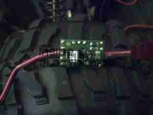
Power Regulator
Power Regulator
Power Regulator
Power Regulator

The regulator, shown above, is a Texas Instruments PTN78060WAZ wide-input voltage adjustable regulator. This module has an exceptionally high efficiency of ~96% at it’s full output current of 3A. The output voltage is set by a precision resistor, soldered to the back of the module, in this case 6.5v. Standard RC connectors are used on the regulator to allow connection between the power switch & the radio receiver.

Receiver Box
Receiver Box

Everything tucked away into place inside the receiver box. The 3S 1000mAh LiPo fits perfectly in the space where the original Ni-Mh hump pack was located.
The completely stable output voltage of the regulator over the discharge curve of the new battery gives a much more stable supply to the radio & ignition, so I should experience fewer dropouts. Plus the fact that the engine now relies on power from the receiver pack to run, it’s a built in fail safe – if the power dies to the receiver, the engine also cuts out.

Posted on Leave a comment

HPI Savage X 4.6 Ignition Conversion – Initial Carburettor Settings & Module Mountings

Ignition Module Mount
Ignition Module
Ignition Module

The engine now with it’s required ignition sensor, it is now mounted back on the chassis of the model. I have replaced the stock side exhaust with a rear silencer, so I could fit the ignition module in place next to the engine.
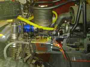
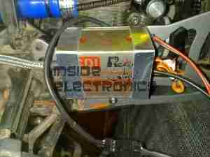
For the mounting, I fabricated a pair of brackets from 0.5mm aluminium, bent around the module & secured with the screws that attach the engine bed plate to the TVPs. The ignition HT lead can be routed up in front of the rear shock tower to clear all moving suspension parts, with the LT wiring tucked into the frame under the engine.
In this location the module is within the profile of the model chassis so it shouldn’t get hit by anything in service.

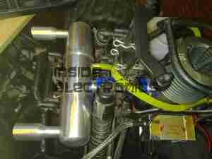
Rear Exhaust
Rear Exhaust

New exhaust silencer fitted to the back of the model. This saves much space on the side of the model & allows the oily exhaust to be discharged away from the back wheel – no more mess to wipe up.

Kill Switch
Kill Switch

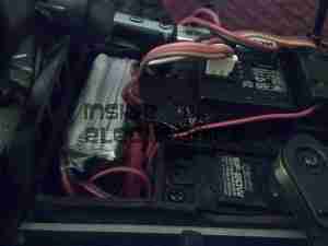
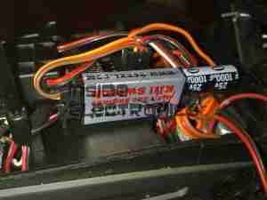
The ignition switch fitted into the receiver box. This is wired into channel 3 of the TF-40 radio, allowing me to remotely kill the engine in case of emergency. I have fitted a 25v 1000µF capacitor to smooth out any power fluctuations from the ignition module.
The radio is running from a 11.1v 1Ah 3S LiPo pack connected to a voltage regulator to give a constant 6.5v for the electronics. I found this is much more reliable than the standard 5-cell Ni-MH hump packs.

Fuel Tank
Fuel Tank

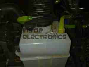
The stock silicone fuel tubing has been replaced with Tygon tubing to withstand the conversion to petrol.

High Speed Needle
High Speed Needle

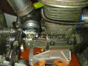
High speed needle tweaked to provide a basic running setting on petrol. This is set to ~1.5mm below flush with the needle housing.
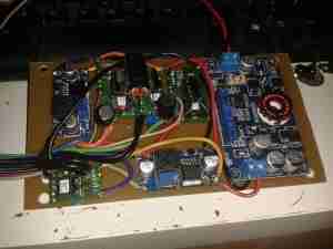
Low Speed Needle
Low Speed Needle

Low speed needle tweaked to provide a basic running setting on petrol. This is set to ~1.73mm from flush with the needle housing.
As petrol is a much higher energy density fuel, it requires much more air than the methanol glow fuel – ergo much leaner settings.
The settings listed should allow an engine to run – if nowhere near perfectly as they are still rather rich. It’s a good starting point for eventual tuning.
 

Posted on Leave a comment

HPI Nitrostar F4.6 Ignition Conversion

As there was no other online example of someone converting a glow/nitro car engine onto CDI ignition, I thought I would document the highlights here.
The engine is currently still running on glow fuel, but when the required fuel lines arrive I will be attempting the switch over to 2-Stroke petrol mix. This should definitely save on fuel costs.

The engine in this case is a HPI NitroStar F4.6 nitro engine, from a HPI Savage X monster truck.

F4.6 Engine
F4.6 Engine

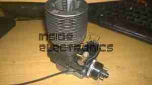
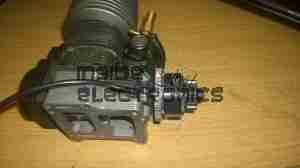
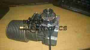
Above is the converted engine with it’s timing sensor. As The installation of this was pretty much standard, a complete strip down of the engine was required to allow the drilling & tapping of the two M3x0.5 holes to mount the sensor bracket to. The front crankshaft bearing has to be drifted out of the crankcase for this to be possible.

Ignition Hall Sensor

Detail of the ignition hall sensor. The bracket has to be modified to allow the sensor to face the magnet in the flywheel. Unlike on an Aero engine, where the magnet would be on the outside edge of the prop driver hub, in this case the hole was drilled in the face of the flywheel near the edge & the magnet pressed in. The Hall sensor is glued to the modified bracket with the leads bent to position the smaller face towards the back of the flywheel.
The clearance from the magnet to sensor is approx. 4mm.

Flywheel Magnet
Flywheel Magnet

Detail of the magnet pressed into the flywheel. A 3.9mm hole was drilled from the back face, approx 2mm from the edge, & the magnet pressed into place with gentle taps from a mallet & drift, as I had no vice to hand.
Initial timing was a little fiddly due to the flywheel only being held on with a nut & tapered sleeve, so a timing mark can be made inside the rear of the crankcase, across the crank throw & case to mark the 28 degree BTDC point, the flywheel is then adjusted to make the ignition fire at this point, before carefully tightening the flywheel retaining nut to ensure no relative movement occurs.
The slots in the sensor bracket allow several degrees of movement to fine adjust the timing point once this rough location has been achieved.

1/4"-32 Spark Plug
1/4″-32 Spark Plug

Definitely the tiniest spark plug I’ve ever seen, about an inch long. Some trouble may be encountered with this on some engines – the electrodes stick out about 2mm further into the combustion chamber than a standard glow plug does. This causes the ground electrode to hit the top of the piston crown. (This happens on the HPI NitroStar 3.5 engine). The addition of another copper washer under the plug before tightening should cure this problem.

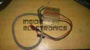
RcExl CDI Ignition Module

Ignition module. Due to the depth of the plug in the heatsink head on these engines, I will have to modify the plug cap to straighten it out, as it will not fit in this configuration.
However, ignition modules are available from HobbyKing with straight plug caps, this makes modification unnecessary

The ignition & components used on this system were obtained from JustEngines.

Posted on Leave a comment

Marine Potable Water Management System

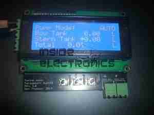
LCD Panel
LCD Panel

Having two separate water tanks on nb Tanya Louise, with individual pumps, meant that monitoring water levels in tanks & keeping them topped up without emptying & having to reprime pumps every time was a hassle.
To this end I have designed & built this device, to monitor water usage from the individual tanks & automatically switch over when the tank in use nears empty, alerting the user in the process so the empty tanks can be refilled.

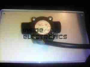
Based around an ATMega328, the unit reads a pair of sensors, fitted into the suction line of each pump from the tanks. The calculated flow is displayed on the 20×4 LCD, & logged to EEPROM, in case of power failure.

Water Flow Sensor
Water Flow Sensor

When the tank in use reaches a preset number of litres flowed, (currently hardcoded, but user input will be implemented soon), the pump is disabled & the other tank pump is enabled. This is also indicated on the display by the arrow to the left of the flow register. Tank switching is alerted by the built in beeper.
It is also possible to manually select a tank to use, & disable automatic operation.
Resetting the individual tank registers is done by a pair of pushbuttons, the total flow register is non-resettable, unless a hard reset is performed to clear the onboard EEPROM.

Main PCB
Main PCB

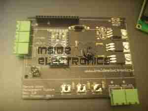
View of the main PCB is above, with the central Arduino Pro Mini module hosting the backend code. 12-24v power input, sensor input & 5v sensor power output is on the connectors on the left, while the pair of pump outputs is on the bottom right, switched by a pair of IRFZ44N logic-level MOSFETS. Onboard 5v power for the logic is provided by the LM7805 top right.

Code & PCB design is still under development, but I will most likely post the design files & Arduino sketch once some more polishing has been done.

Posted on Leave a comment

Wearable Raspberry Pi – Some Adjustments

USB Hub
USB Hub

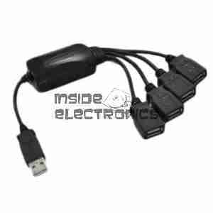
As the first USB hub I was using was certainly not stable – it would not enumerate between boots & to get it working again would require waiting around 12 hours before applying power, it has been replaced. This is a cheapie eBay USB hub, of the type shown below.

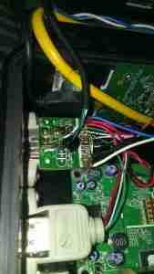
These hubs are fantastic for hobbyists, as the connections for power & data are broken out on the internal PCB into a very convenient row of pads, perfect for integration into many projects.

Breakout Hub
Breakout Hub

I now have two internal spare USB ports, for the inbuilt keyboard/mouse receiver & the GPS receiver I plan to integrate into the build.

These hubs are also made in 7-port versions, however I am not sure if these have the same kind of breakout board internally. As they have the same cable layout, I would assume so.


Connector Panel
Connector Panel

Here is a closeup of the back of the connectors, showing a couple of additions.

I have added a pair of 470µF capacitors across the power rails, to further smooth out the ripple in the switching power supply, as I was having noise issues on the display.

Also, there is a new reset button added between the main interface connectors, which will be wired into the pair of pads that the Raspberry Pi has to reset the CPU.
This can be used as a power switch in the event the Pi is powered down when not in use & also to reset the unit if it becomes unresponsive.


Posted on Leave a comment

Wearable Raspberry Pi Part 2.5 – Battery Pack PCM

Battery PCM
Battery PCM

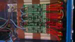
The final part for the battery pack has finally arrived, the PCM boards. These modules protect the cells by cutting off the power at overcharge, undercharge & overcurrent. Each cell is connected individually on the right, 12v power appears on the left connections. These modules also ensure that all the cells in the pack are balanced.


Posted on Leave a comment

Wearable Raspberry Pi SMPS Modifications

SMPS Mods
SMPS Mods

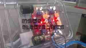
A few modifications were required to the SMPS modules to make the power rails stable enough to run the Pi & it’s monitor. Without these the rails were so noisy that instability was being caused.

I have replaced the 100µF output capacitors & replaced them with 35v 4700µF caps. This provides a much lower output ripple.

There are also heatsinks attached to the converter ICs to help spread the heat.

Posted on Leave a comment

Wearable Raspberry Pi Part 2 – Power Supply

All Fitted
All Fitted

Progress is finally starting on the power supply unit for the Pi, fitted into the same case style as the Pi itself, this is an 8Ah Li-Poly battery pack with built in voltage regulation.

Regulator Boards
Regulator Boards

Here are the regulators, fixed to the top of the enclosure. These provide the 12v & 5v power rails for the Pi unit, at a max 3A per rail.

Battery Pack
Battery Pack

In the main body of the case the battery pack is fitted. This is made up of 4 3-cell Li-Poly RC battery packs, rated at 2Ah each. All wired in parallel this will provide a total of 8Ah at 12.6v when fully charged.

Powered Up
Powered Up

Here the regulators are powered up from a 13v supply for testing. I have discovered at full load these modules have very bad ripple, so I will be adding extra smoothing capacitors to the power rails to compensate for this.

I/O
I/O

Here are the connectors on the top of the unit, outputting the two power rails to the Pi & the DC barrel jack that will be used to charge the pack.


Posted on 3 Comments

Wearable Raspberry Pi Part 1

Overview
Overview

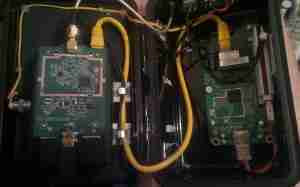
Here is the project I’m currently working on. A completely wearable computing platform based on the Raspberry Pi & the WiFi Pineapple.

Above can be seen the general overview of the current unit.

On the left:

  • Alfa AWUS036NHA USB High Power WiFi Network Interface
  • 512MB Model B Raspberry Pi, 16GB SD card, running Raspbian & LXDE Desktop. Overclocked to 1GHz.

On the right:

  • WiFi Pineapple router board
  • USB 3G card.

The WiFi, Pineapple & 3G all have external antenna connections for a better signal & the whole unit locks onto the belt with a pair of clips.
The Raspberry Pi is using the composite video output to the 7″ LCD I am using, running at a resolution of 640×480. This gives a decent amount of desktop space while retaining readability of the display.

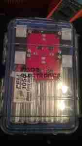
The case itself is a Pelican 1050 hard case, with it’s rubber lining removed. The belt clips are also a custom addition.

Connections
Connections

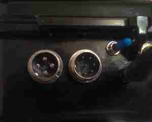
Here are the connections to the main unit, on the left is the main power connector, supplying +5v & +12v DC. The plug on the right is an 8-pin connection that carries two channels of video, mono audio & +12v power to the display.
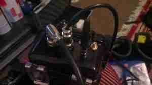
Currently the only antenna fitted is the 3G.

Connectors
Connectors

Closeup of the connections for power, audio & video. The toggle switch is redundant & will soon be replaced with a 3.5mm stereo jack for headphones, as an alternative to the mono audio built into the display.

Test Run
Test Run

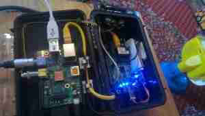
Current state of test. Here the unit is running, provided with an internet connection through the Pineapple’s 3G radio, funneled into the Pi via it’s ethernet connection.

Pi Goodness!
Pi Goodness!

Running on a car reversing camera monitor at 640×480 resolution. This works fairly well for the size of the monitor & the text is still large enough to be readable.


Stay tuned for Part 2 where I will build the power supply unit.


Posted on Leave a comment

DIY Valve Amplifier – Part 1 – Amplifier Section

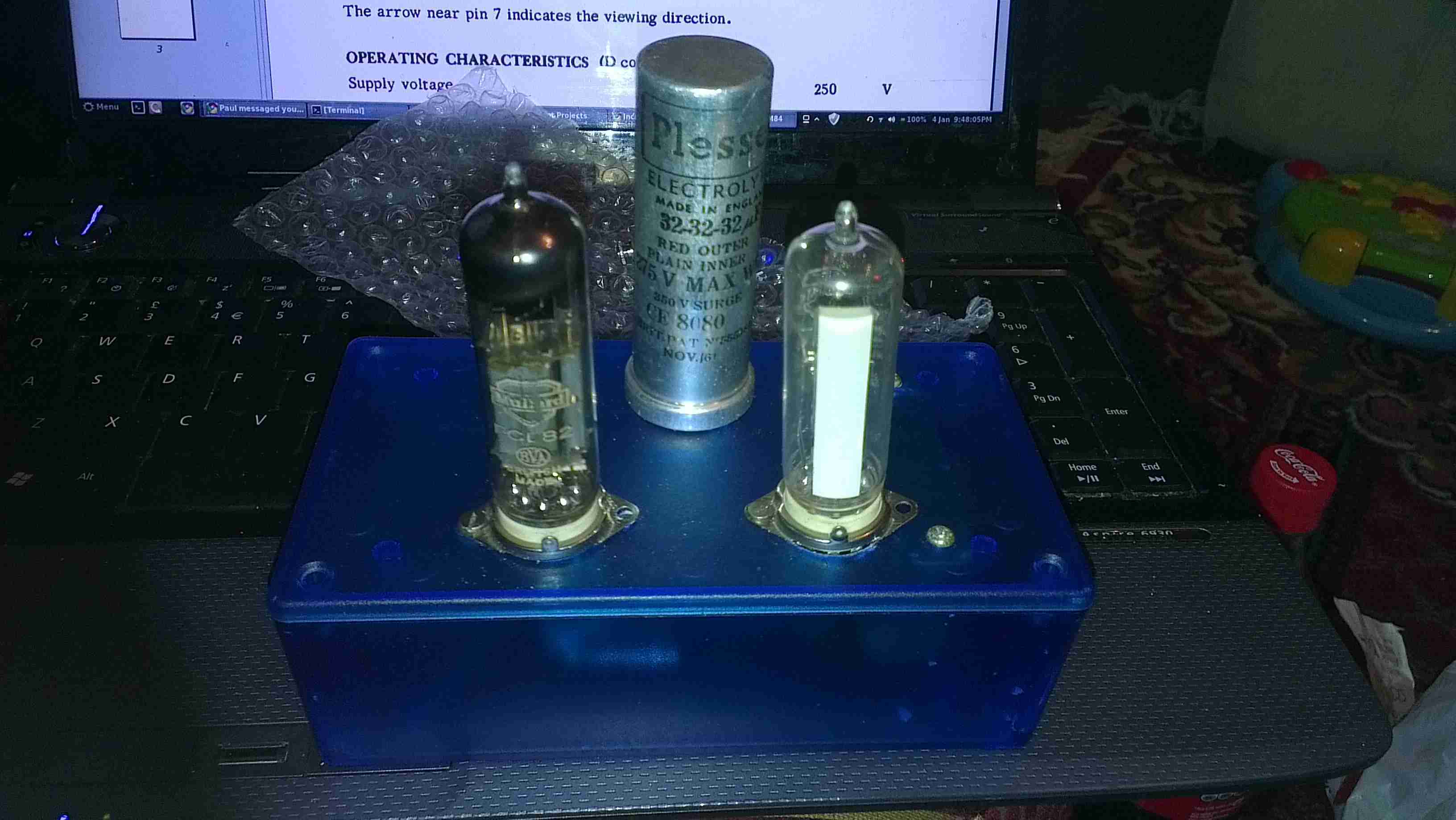
Components
Components

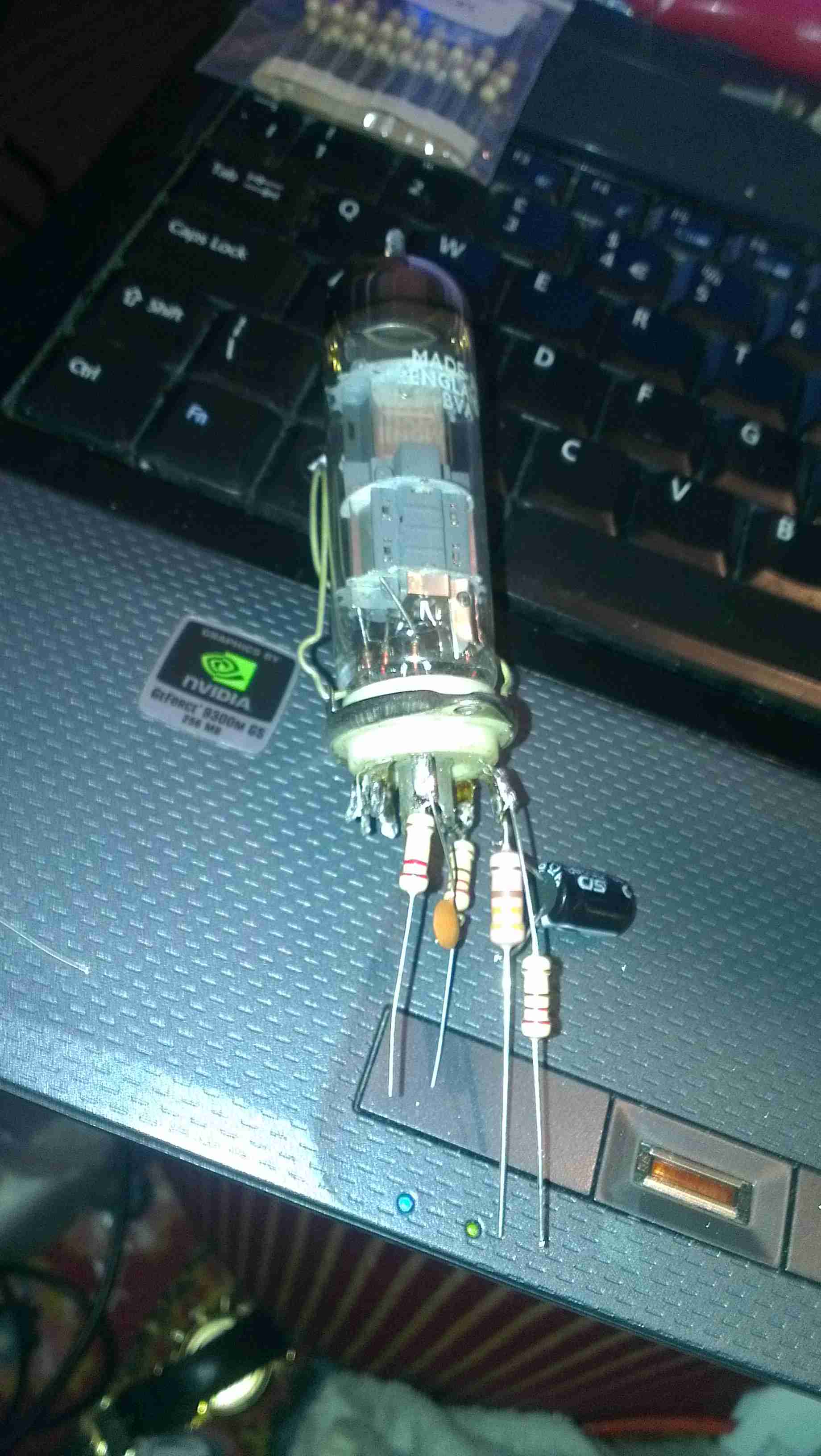
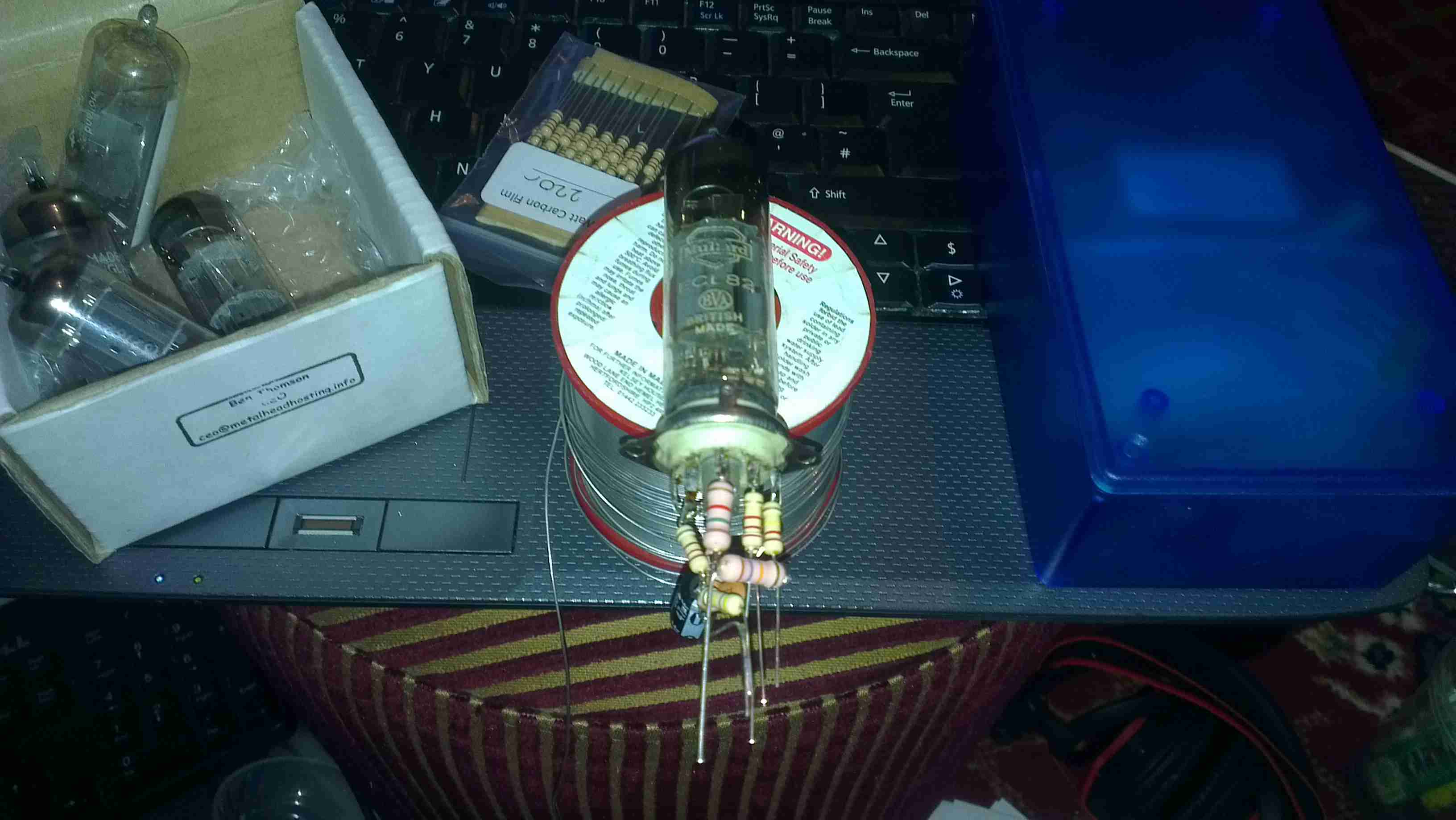
Here are a few details of a valve amplifier I am building, using the valve related parts from a 1960’s reel to reel tape recorder.

This amplifier is based on an a Mullard ECL82 triode/pentode valve, with an EM84 magic eye tube for level indication.

Beginnings Of The Amplifier

Here the first components are being soldered to the tags on the valve holder, there are so few components that a PCB is not required, everything can be rats-nested onto the valve holders.

Progress
Progress

Progressing with the amplifier section componentry, all resistors are either 1/2W or 2W.

Valve Sockets Fitted

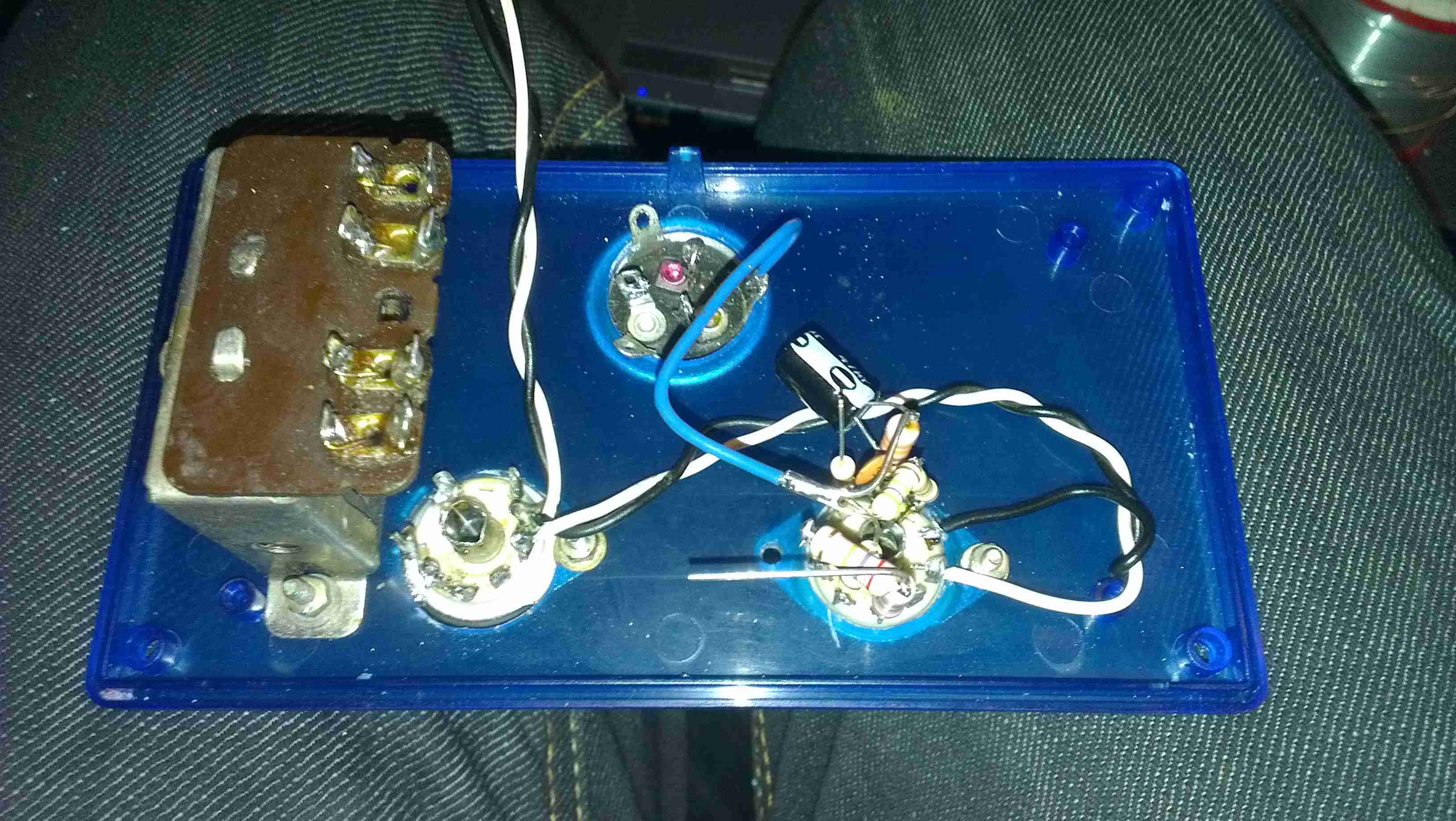
Here the valve holders have been fitted, along with the output transformer, DC smoothing capacitor & the filament wiring, into the top of the plastic housing. At this point all the components that complete the amplifier section are soldered to the bottom of the right hand valve holder.

Wiring
Wiring

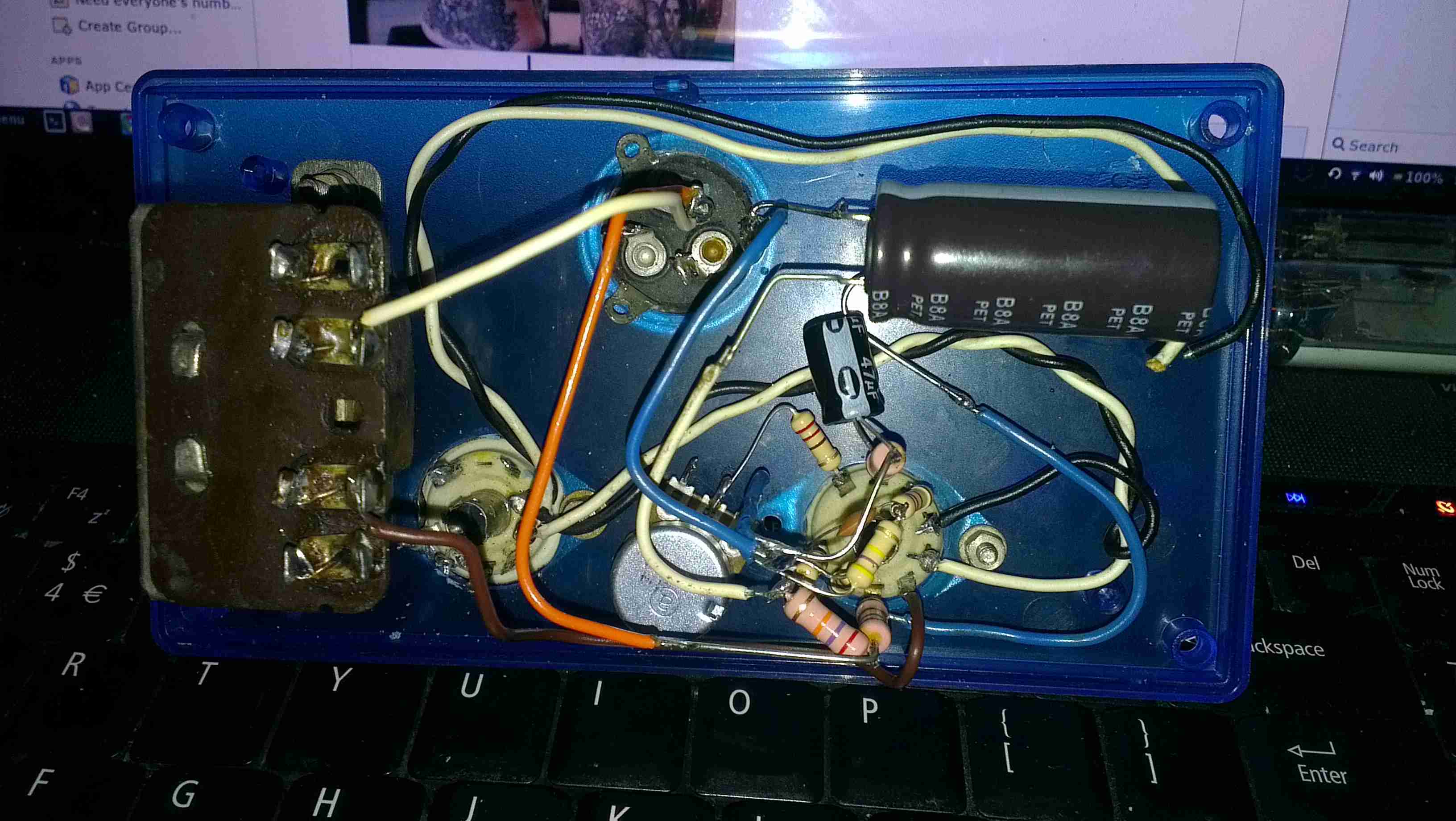
Starting the wiring between the valves & the power supply components. The volume control pot is fitted between the valve holders.

Valves Test Fit
Valves Test Fit

The valves here are test fitted into their sockets, the aluminium can at the back is a triple 32uF 250v electrolytic capacitor for smoothing the B+ rail.

Amplifier Section First Test

First test of the amplifier, with the speaker from the 1960’s tape recorder from which the valves came from. the 200v DC B+ supply & the 6.3v AC filament supply is derived from the mains transformer in the background.

Magic Eye Tube Added

Here the magic eye tube has been fitted & is getting it’s initial tuning to the amplifier section. This requires selecting combinations of anode & grid resistors to set the gap between the bars while at no signal & picking a coupling RC network to give the desired response curve.

Final Test
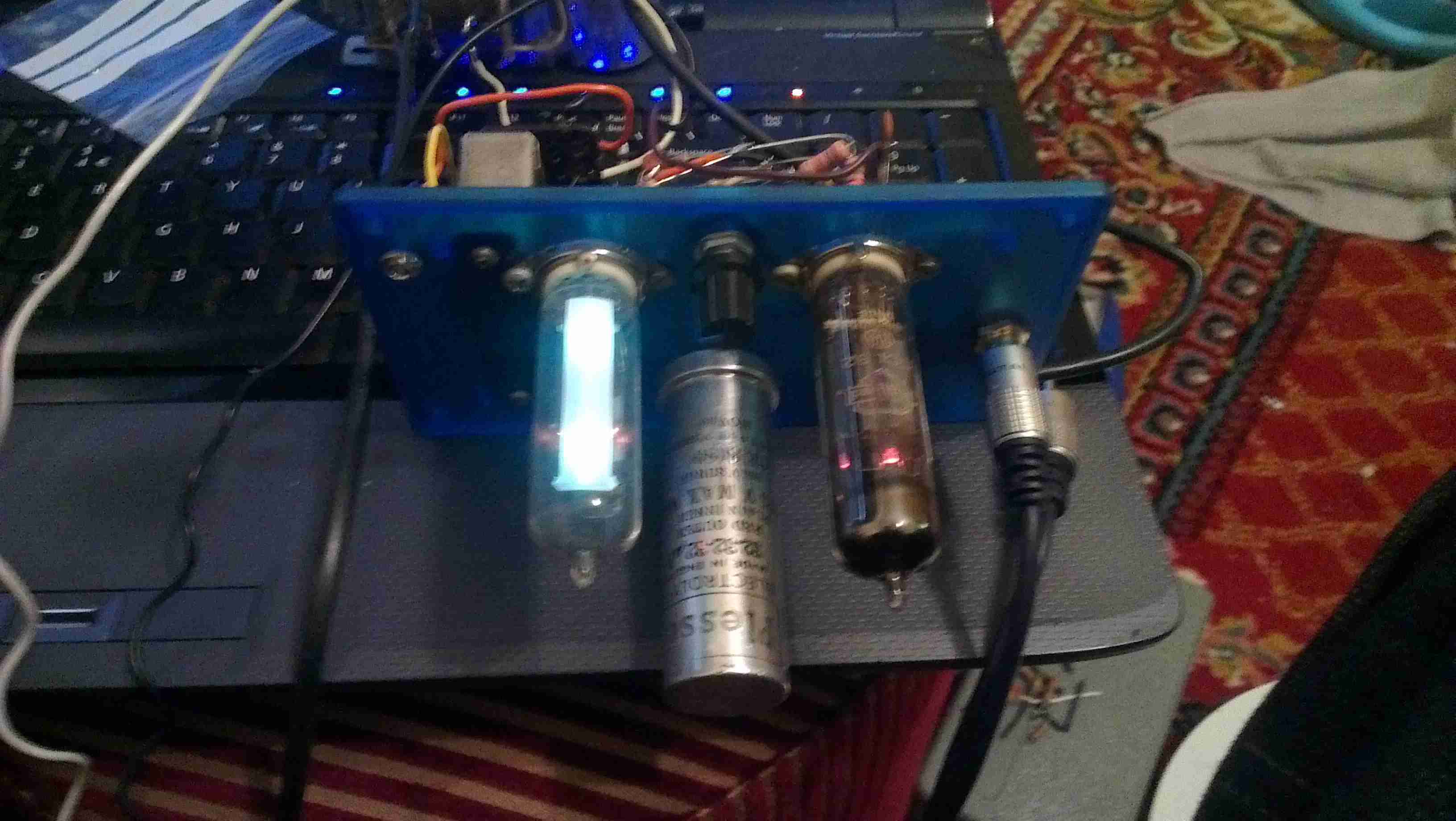
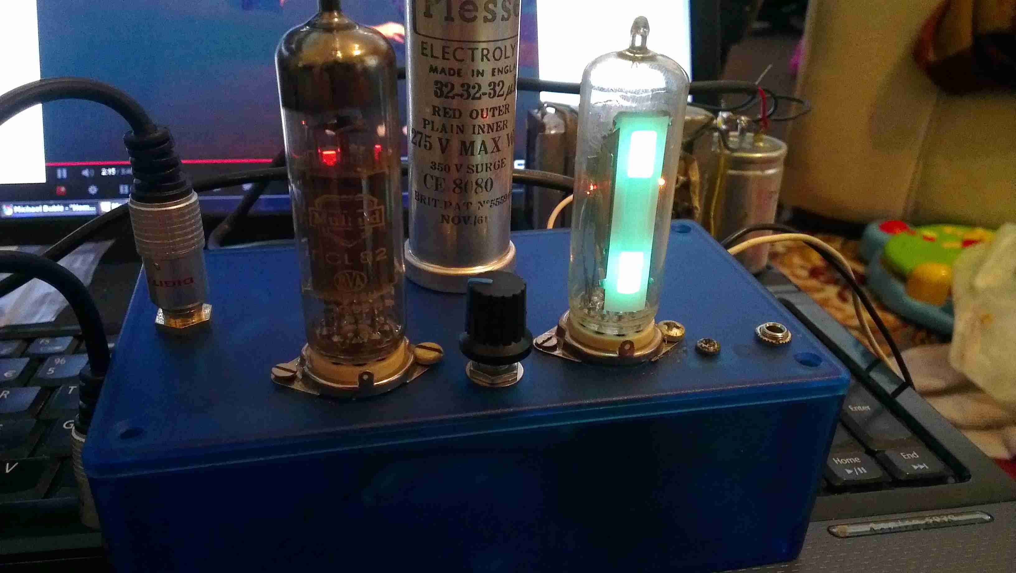
Final Test

Here both valves are fitted & the unit is sitting on it’s case for final audio testing. the cathodes of the ECL82 can be clearly seen glowing dull red here.


In the final section, I will build a SMPS power supply into the unit to allow it to be powered from a single 12v DC power supply.

Posted on Leave a comment

Media PC Build Log

Front
Front

This will be the record of building a new Media PC, above you can see the finished system.

It’s Mini-ITX based, with on-board HDMI output, specifically to run XBMC via Fedora for media purposes.

CiC MTX001B Mini-ITX Case

This is the case that is being used, around the size of a Shuttle PC. It has a single 3.5″ & 5 1/4″ bay, for a HDD & ODD, front panel USB, Firewire & Audio.

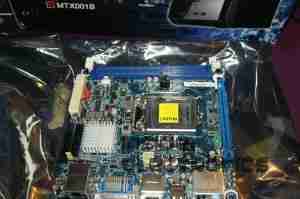
Intel BLKDH57JG Mini-ITX Motherboard

Motherboard to fit the case. Supports Intel Core i5 series CPUs, with up to 8GB of DDR3 RAM.
Other features are on-board full surround audio, HDMI, eSATA, & a single 16x PCIe slot.

Corsair 4GB DDR3 DIMMs

Matching memory for the motherboard, a pair of 4GB DDR3 units.

Akasa K25 Low Profile CPU Cooler

Having never been impressed by bundled coolers with CPUs, here is an aftermarket low-profile unit, with solid copper core for enhanced cooling. This cooler is specially designed for Mini-ITX uses.

Intel Core i5 650 Dual Core 3.2GHz CPU

The brains of the operation, Core i5 650 CPU, should handle HD video well.

Posted on Leave a comment

Raspberry Pi GPIO Breakout

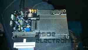
Board Built
Board Built

After seeing these on eBay for £8.99 I thought it might be a good deal – interfacing with the RasPi’s GPIO & it has built in power supplies.

As a kit, it was very easy to assemble, the PCB quality is high, and is a fairly good design. It worked first time, the regulators hold the rails at the right voltages.
However there are some issues with this board that bug me.

The documentation for the kit is *AWFUL*. No mention of the regulators on the parts list & which goes where – I had to carefully examine the schematics to find out those details.
The 4x 1N1007 diodes required weren’t even included in the kit! Luckily I had some 1N4148 high speed diodes lying around & even though they’re rated for 200mA continuous rather than the specified part’s 1A rating, the lack of heatsinking on the regulators wouldn’t allow use anywhere near 1A, so this isn’t much of a problem.

Component numbering on the silkscreen isn’t consistent – it jumps from R3 straight to R6! These issues could be slightly confusing for the novice builder, and considering the demographic of the RasPi, could be seen as big issues.

On the far left of the board are the 5v & 3.3v regulators, well placed on the edge of the board in case a heatsink may be required in the future. However the LM317 adjustable regulator is stuck right in the middle of the PCB – no chance of being able to fit a heatsink, & the device itself seems incredibly cheap – the heatsink tab on the back of the TO-220 is the thinnest I have ever seen. Not the usual 2-3mm thick copper of the 5v & 3.3v parts – but barely more than a mm thick, so it’s not going to be able to cope with much power dissipation without overheating quickly.

As the adjustable rail can go between ~2.5v – 10v, at the low end of the range the power dissipation is going to shoot through the roof.

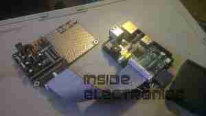
The GPIO connector – this could have been done the other way, at the moment the ribbon cable has to be twisted to get both the Pi & the GPIO board the same way up. Just a slight fail there. See the image below

Plugged In
Plugged In

The power rails are not isolated out of the box – there is no connection between the 5v & 3.3v rails & the Pi’s GPIO, but the GND connections are linked together on the board.

Getting the ribbon cable through the  hole in the ModMyPi case was a bit of a faff – the connector is too big! I had to squeeze the connector through at a 45° angle. The case is also remarkably tight around the connector once it’s fitted to the board – clearly the designers of the case didn’t test the an IDC connector in the case before making them!
Everything does fit though, after a little modification.

All Cased Up
All Cased Up

Here is the unit all built up with the case. The top cover just about fits with the IDC connector on the GPIO header.

More to come once I get some time to do some interfacing!


Posted on Leave a comment

ModMyPi Raspberry Pi Case

Fitted Pi
Fitted Pi

Finally, some protection for my Raspberry Pi! The PCB fit is slightly loose, but that was quickly sorted with the application of a couple of spots of hot glue in the corners.

Unfortunately, the case is a couple of mm too small to fit the main board from the Pico Projector inside, so I won’t be butchering that into the case with the Pi as yet. What is required is an interface to the display engine from the Pi’s DSI interface.


Pi Cased Up
Pi Cased Up

The pi all boxed. up. The only thing that this case would now require is a lightpipe to direct the LED’s light to the openings in the case, as they are very difficult to see at present.