Having now tested the supply I wrote about in my previous post, I can now say that it’s nameplate rating far exceeds it’s actual capability.
On running the supply under load, at 6.5A the operating frequency drops into the audible range, a big sign of overload. (It makes an irritating continuous chirping noise). The output voltage also drops to 10.5v.
The temperature of the unit while it’s been running under such a load is also questionable, the external casing gets hot enough to cause burns, I haven’t yet been able to stick a thermocouple into the case to see what the internal temperature is.
I’m currently talking with the eBay seller (wwwstation) regarding this, however they are arguing that the supply is only for LEDs & CCTV cameras.
However those two loads are very different, and the supply has no internal regulation for supplying LEDs. As a simple switchmode supply, any load is suitable, providing it’s within the load rating of the supply.
I would estimate that the supply is only capable of 5A as an upper limit.
They are requesting that I return the supply, but I’m yet to find out if they’re going to cover return postage. The item as listed is not as described, and I will escalate things if required.
I will update this post when I hear more back from the eBay seller.
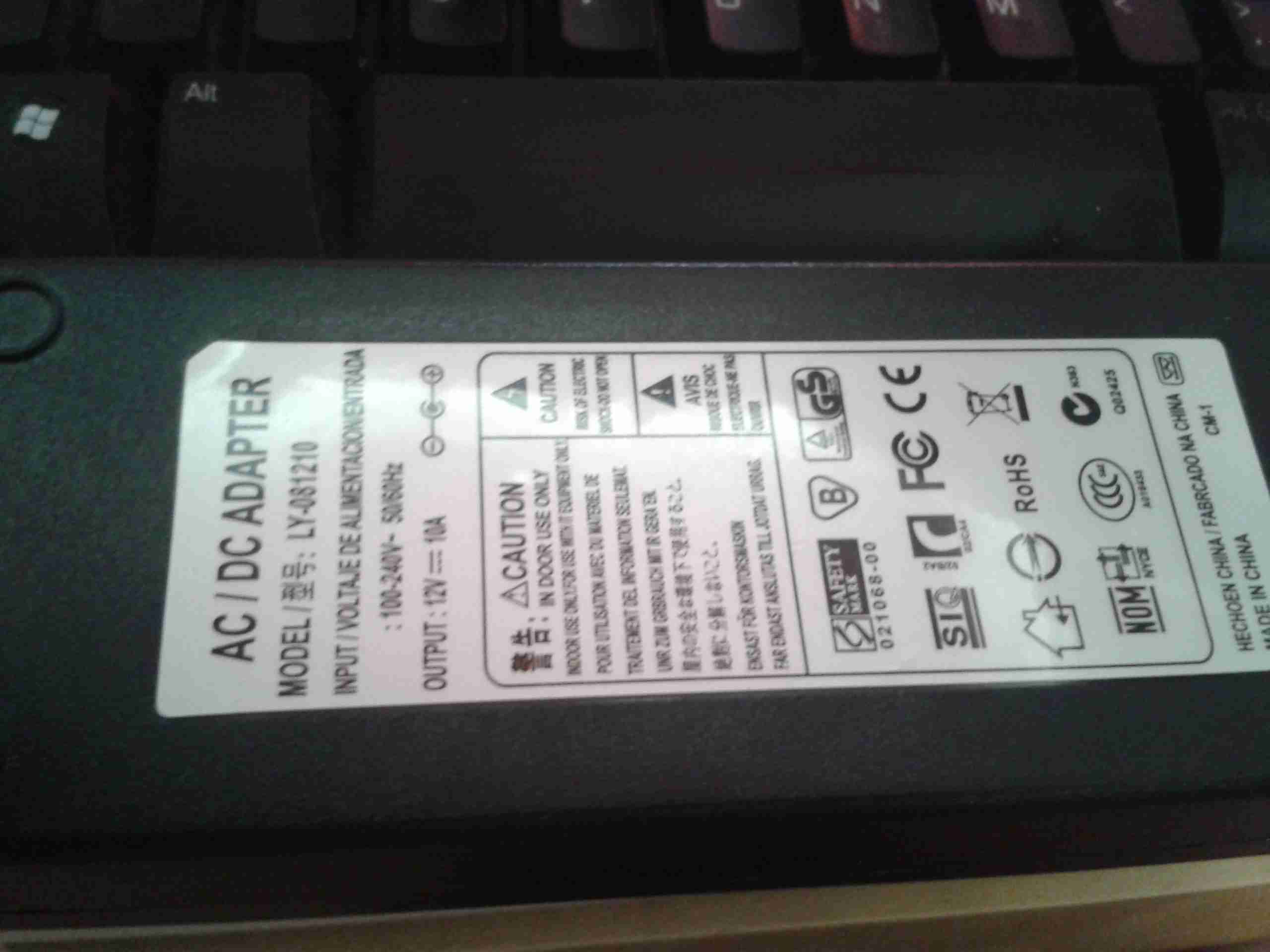
I recently ordered a PSU to run one of the TVs I converted to 12v operation, and being an older TV, it’s a fairly heavy load at 6.5A. eBay to the rescue again, with a cheap 10A rated supply.
Power Brick
Like all similar supplies these days, it’s a SMPS unit, and feels suspiciously light for it’s power rating.
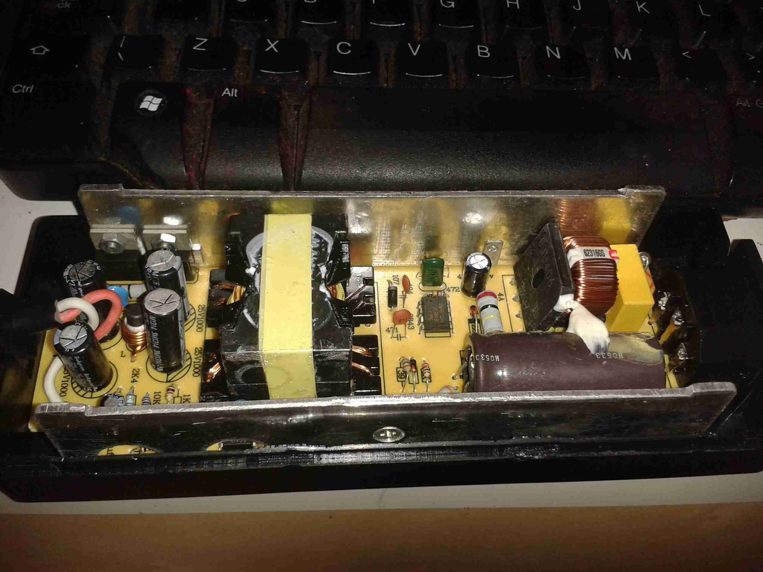
Cover Removed
Luckily this one is easy to get into, no ultrasonic welding on the case, just clips. Here’s the top cover removed, big alloy plate between the heatsinks.
PCB
The top heatsink plate was glued to the top of the transformer with silicone, some gentle prying released it. From the top, things don’t look too bad. There’s some filtering on the mains input & it’s even fused!
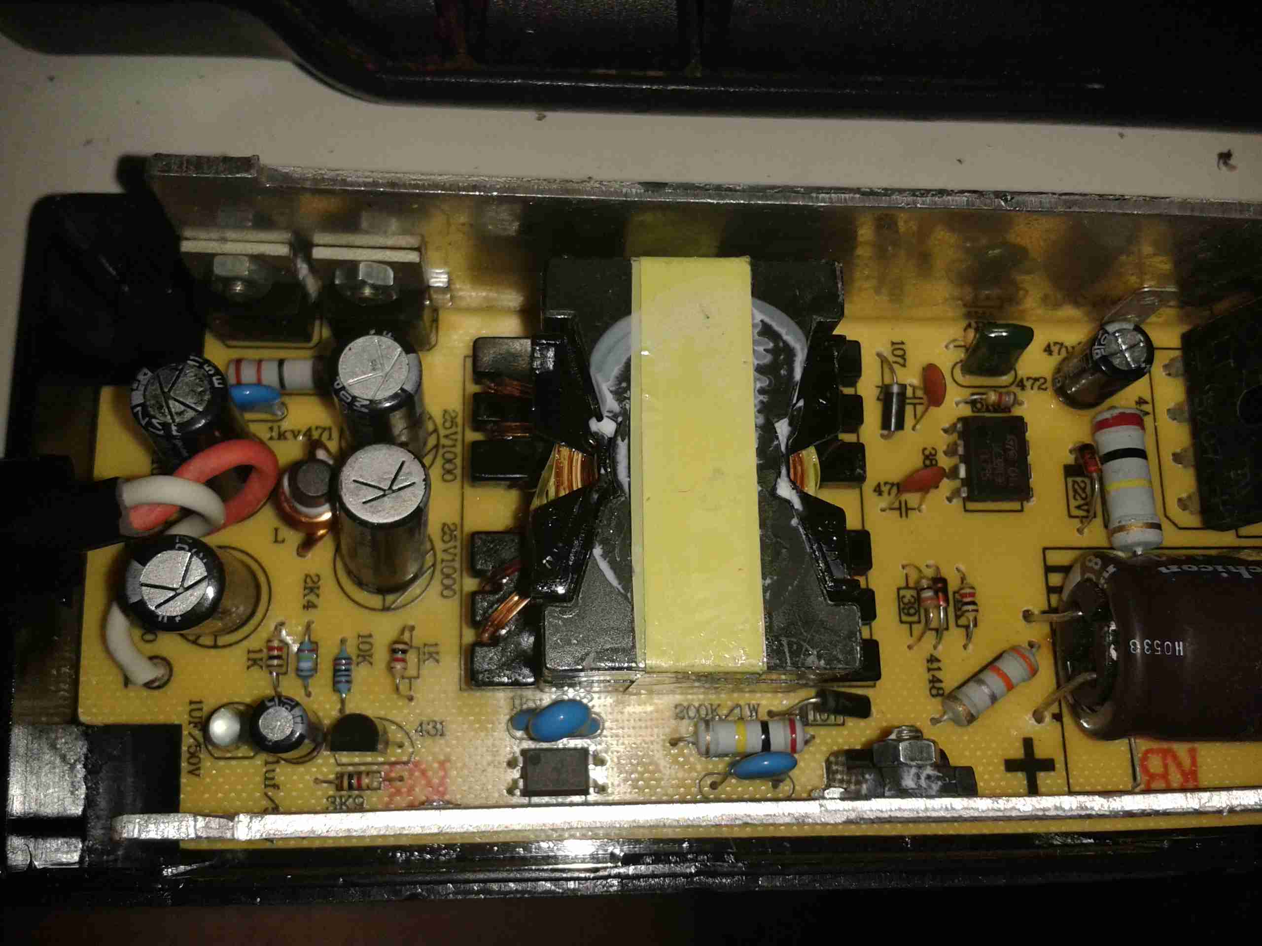
Primary Side
Here’s a closeup of the primary side of the PSU, the main DC bus capacitor is a Nichicon one, but it’s clearly been recovered from another device, look at the different glue on the end!
it’s also flapping about in the breeze, the squirt of silicone they’ve put on does nothing to stop movement.
Also here is the mains input fuse, filter capacitor & common mode choke. At least there is some filtering!
The main control IC is a UC3843B High Performance Current Mode PWM Controller, operating at a switching frequency of 250kHz.
The main switching transistor is visible at the bottom left corner, attached to the heatsink.
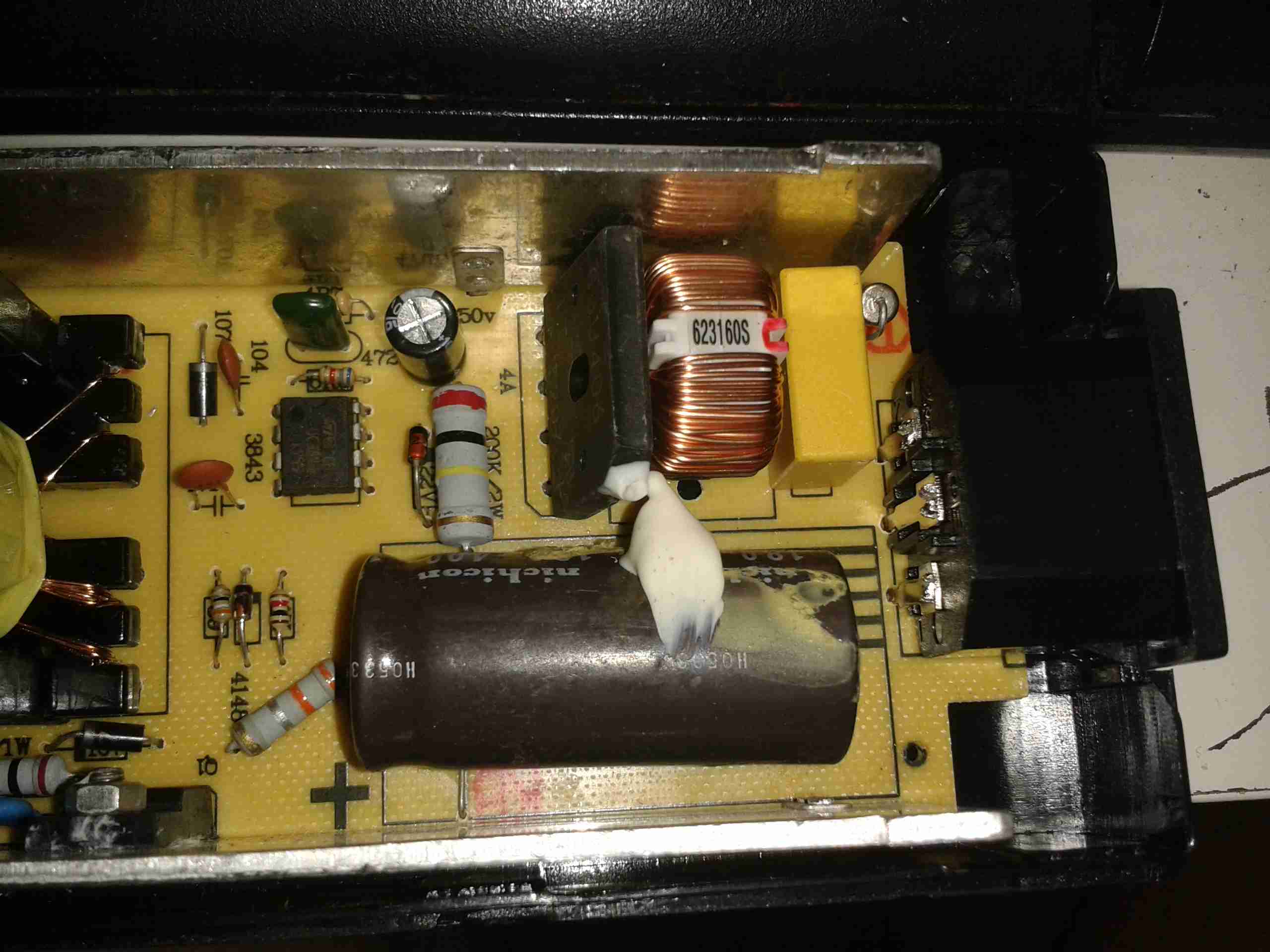
Secondary Side
Here’s the secondary side of the supply. The transformer itself is OK, nice heavy windings on the output to suit the high current.
It’s using proper opto-isolated feedback for voltage regulation, with a TL431 reference IC.
The output diodes are attached to the heatsink at the top of the photo, I couldn’t read any numbers on those parts.
The output filter capacitors are low quality, only time will tell if they survive. I’ll put the supply under full load & see what the temperature rise is inside the casing.
PCB Bottom
On the bottom of the PCB things get a little more dire. There isn’t really much of an isolation gap between the primary & secondary sides, and there’s a track joining the output negative with mains earth, which gets to within 2mm of the live mains input!
As with all these cheapo supplies, there’s good points & bad points, I will update when I’ve had a chance to put the supply under full load for a while & see if it explodes!
With every piece of Chinese electronics I obtain, mainly Baofeng radios, they come with a Europlug-type power adaptor, and a universal plug adaptor for the mains.
The charger units aren’t too bad, there’s a fair amount of isolation between the primary & secondary, and even though they’re very simple & cheap, I can’t see any immediate safety problems with them.
The plug adaptors, however, are a different matter. These things are utterly lethal!
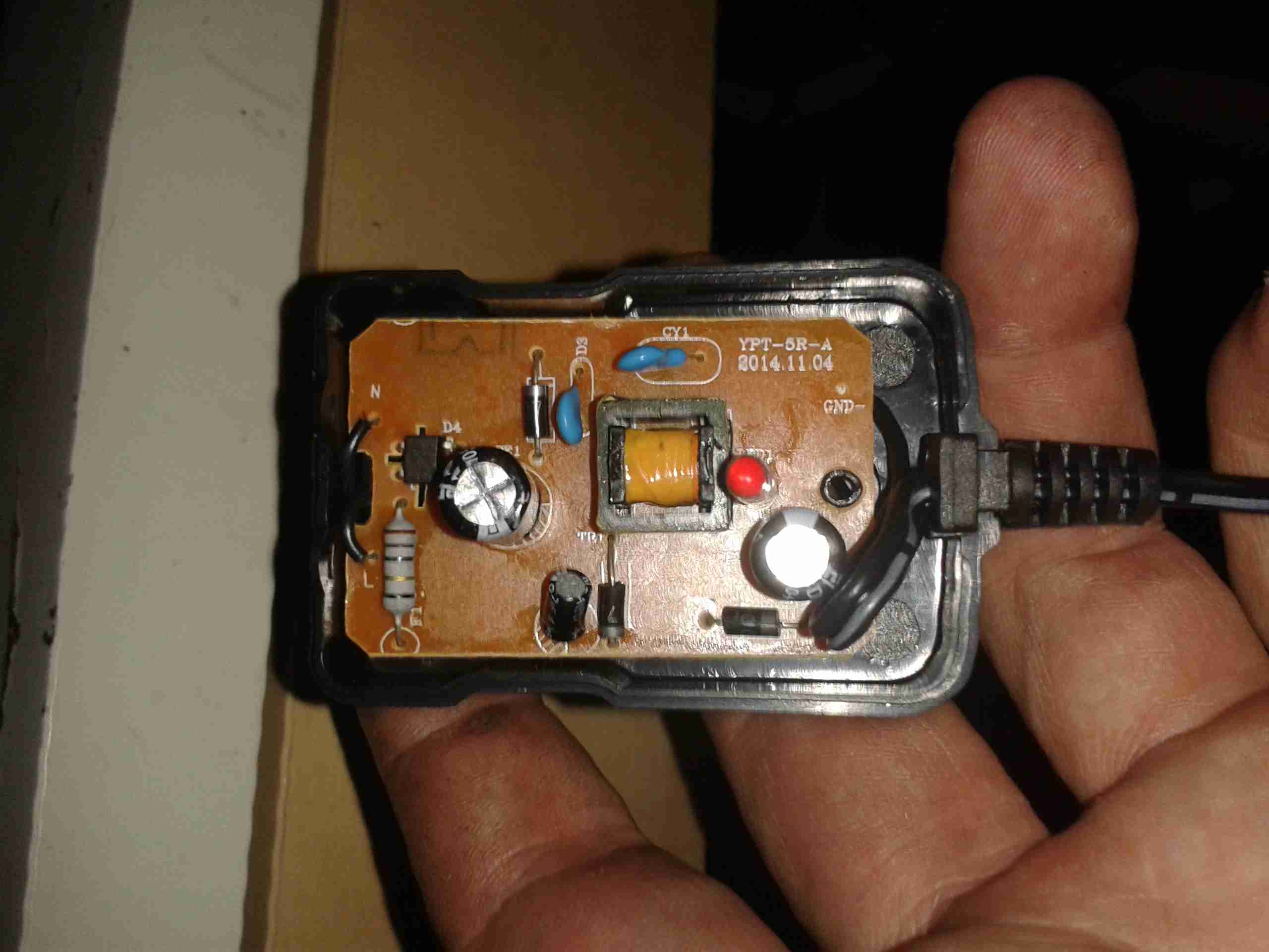
Baofeng PSU
Here’s the inside of the PSU. It’s just a very simple SMPS, giving an output of 10v 500mA. The fuse is actually a fusible resistor.
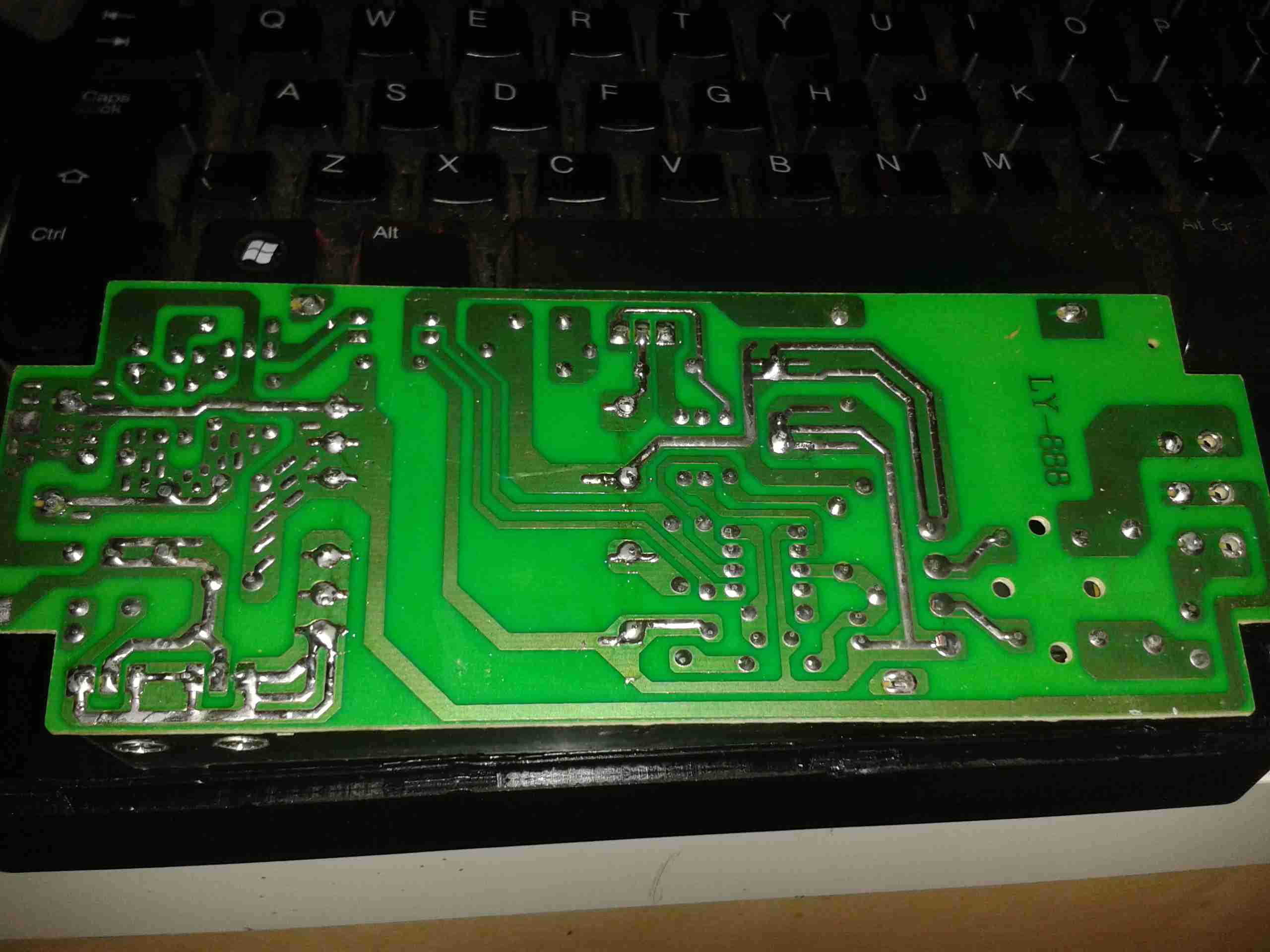
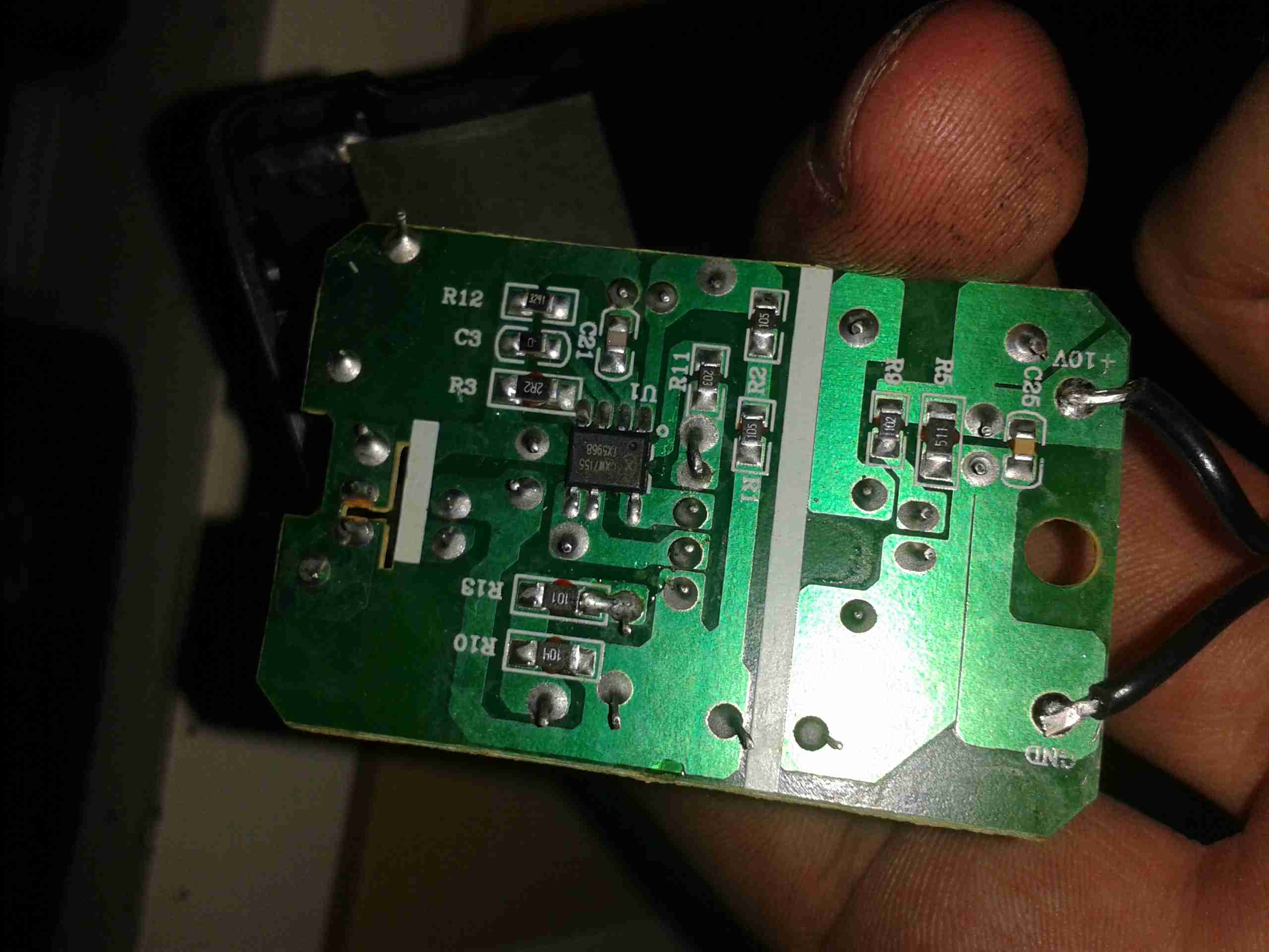
PCB Reverse
Here’s the back of the PCB with the SMPS control IC. I can’t find any English datasheets for this part unfortunately.
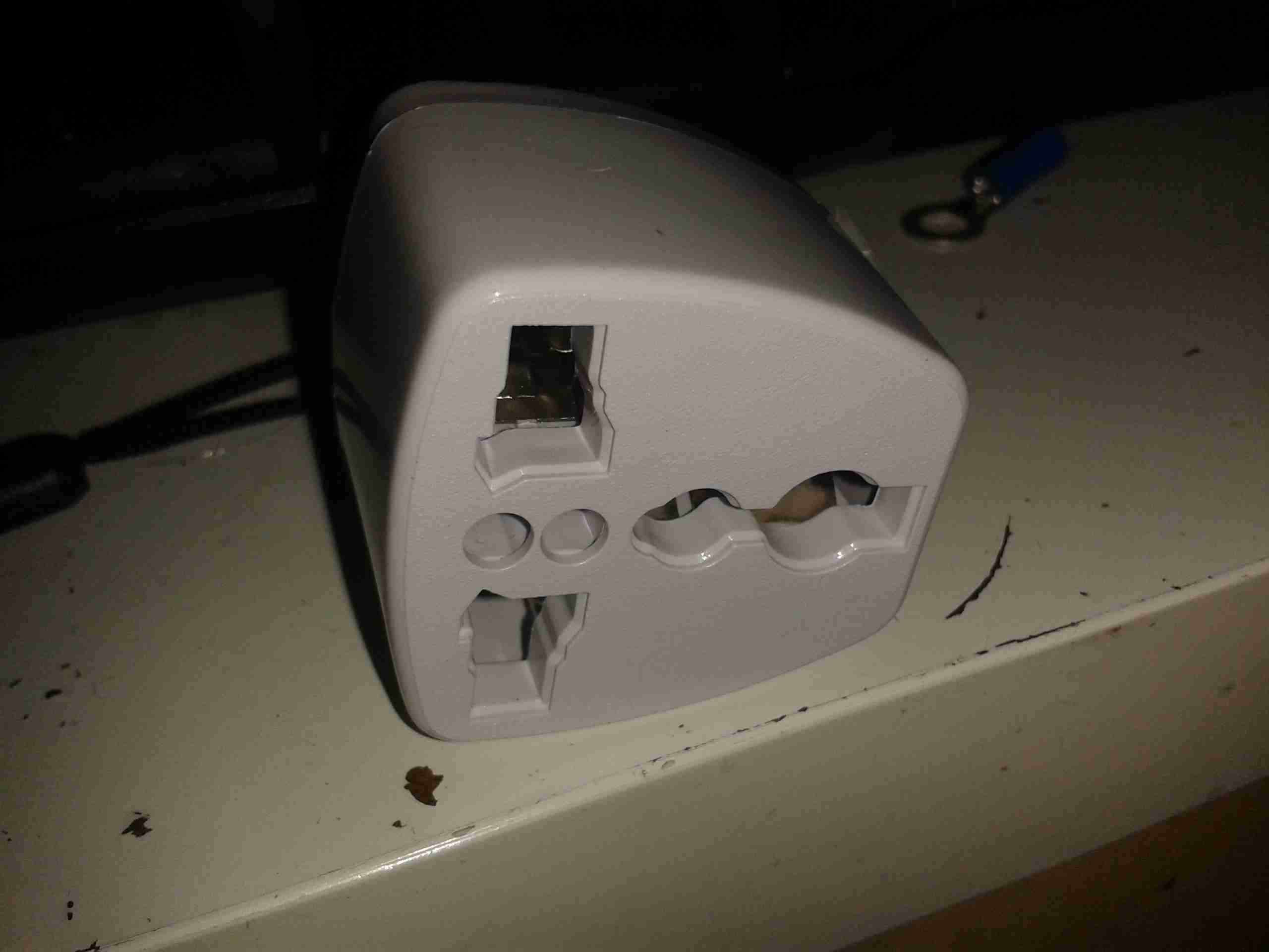
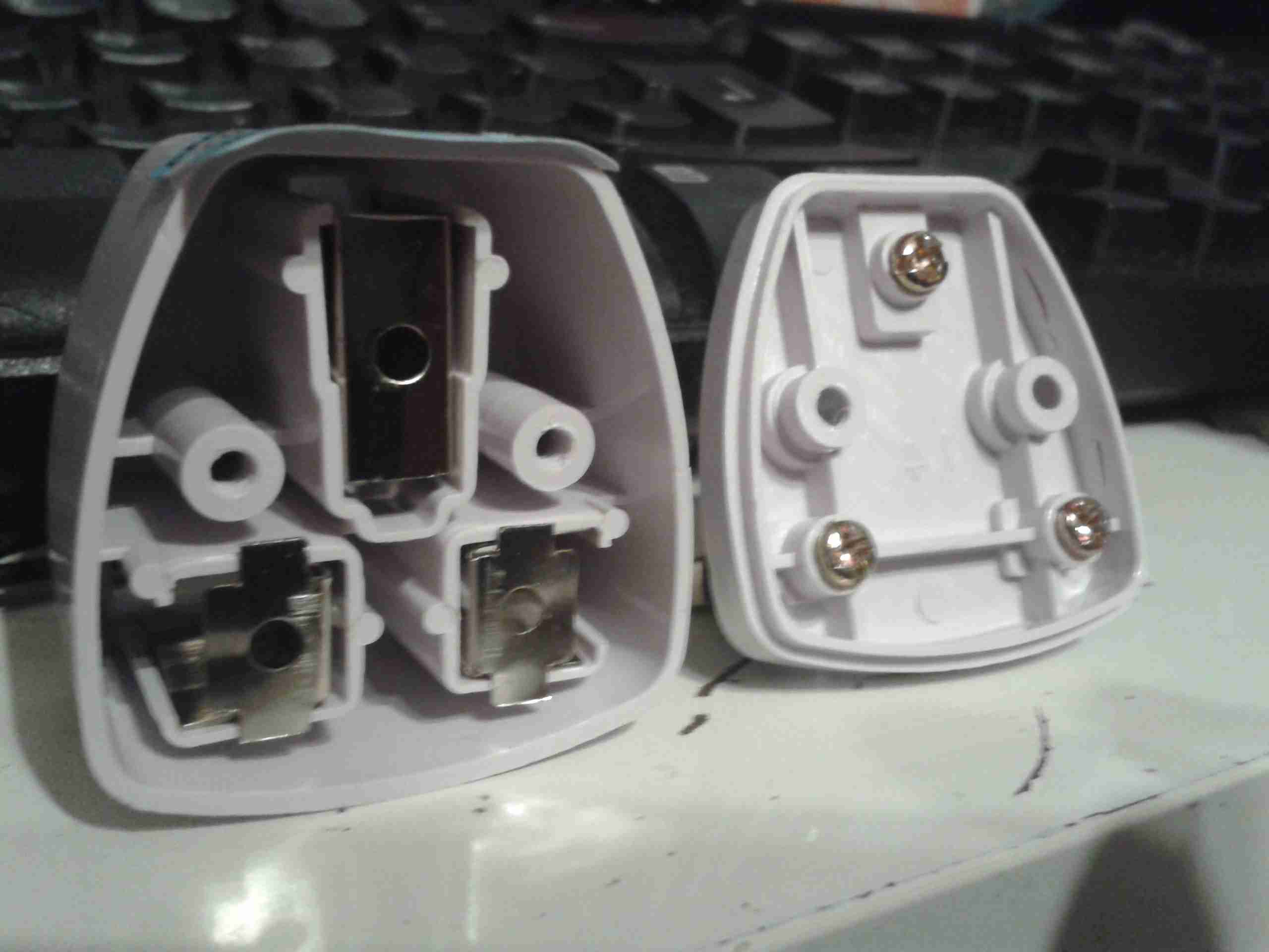
Universal Travel Adaptor
Here’s the dangerous adaptor. There’s no safety shield, so the live parts are exposed.
Internals
Here’s the adaptor split apart. The output contacts are on the left, and rely just on pressure to make contact with the brass screws on the mains input pins to provide power.
This is a very poor way to get a connection, a dirty or worn contact here would create a lot of heat if any significant power is pulled through, and could quite possibly result in a fire.
Not surprisingly, I bin these things as soon as I open the box, and charge all my radios with a 12v charging system.
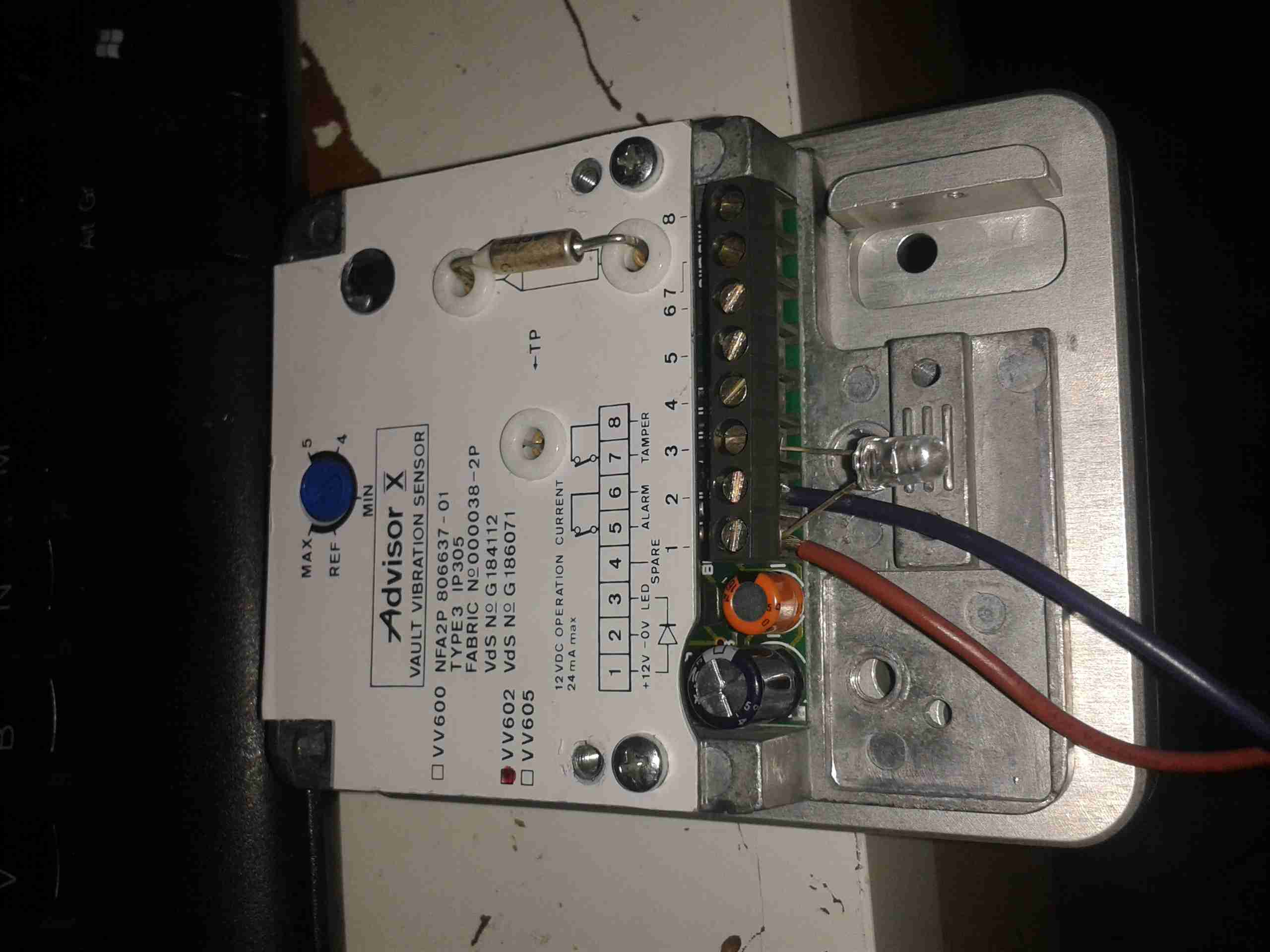
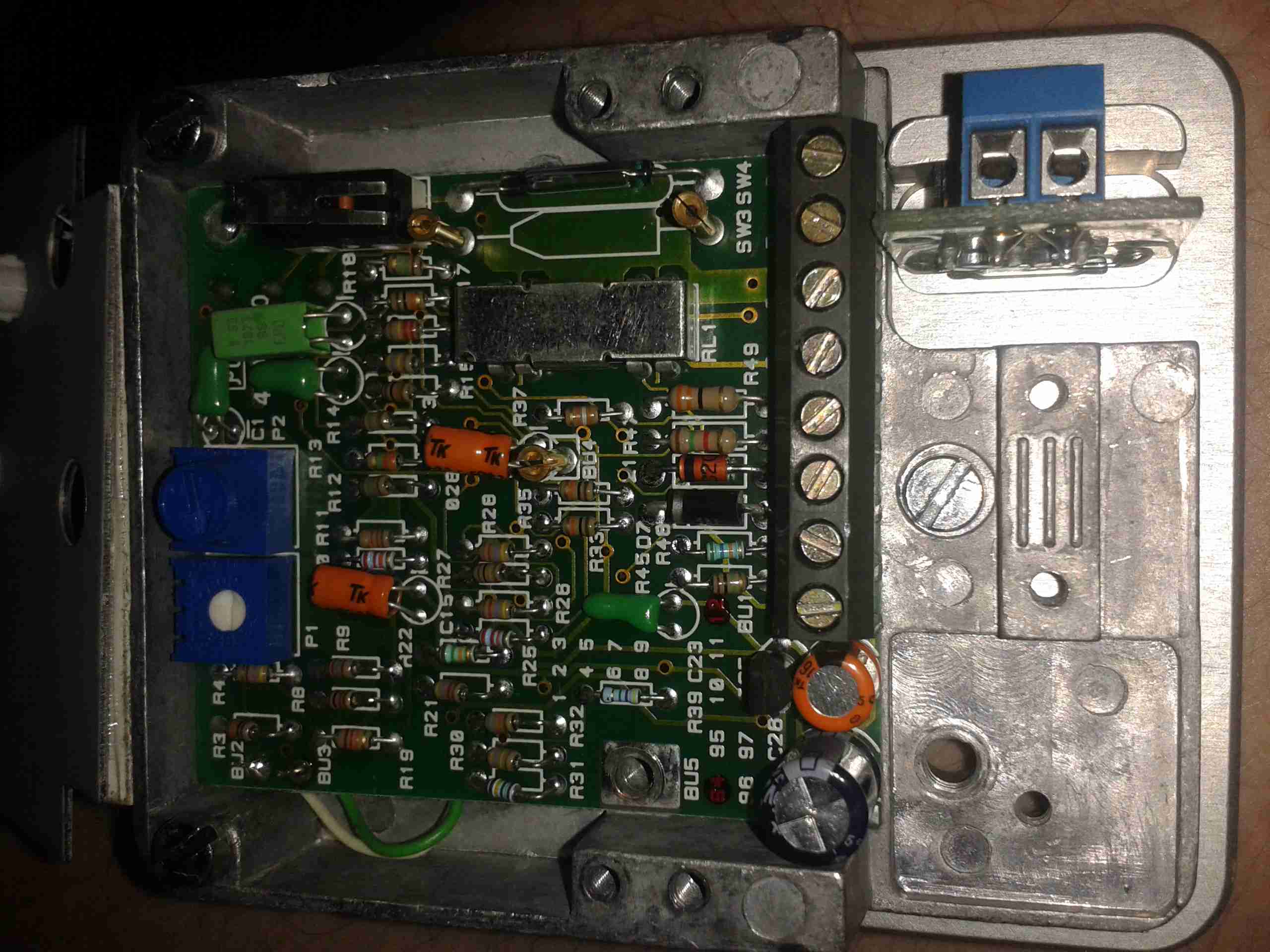
Here’s a rather unique device for protecting safes & vaults from attack by thefts.
It’s an Aritech VV602 seismic detector, based on piezoelectric sensors. Not surprisingly, this unit is covered in tamper sensors as well. There are several different sensor types in use:
Piezoelectric vibration sensing
Thermal sensing
Magnetic sensing
Manual Tamper Switches
Sensor Unit
Above is the main unit, with the thermal sensor. This is just a thermal fuse, very commonly used in everything from room heaters to hairdryers. This one triggers at 84°C. The adjustment pot is also visible here.
Mounting Plate
Above is the magnetic mounting plate used to attach the device to the safe. These units are apparently mounted over the keyhole of the safe to protect the lock, so they need to be easily removable to access the safe. This is a very strong magnet & it isn’t possible to pull it from a metal object without triggering the sensor.
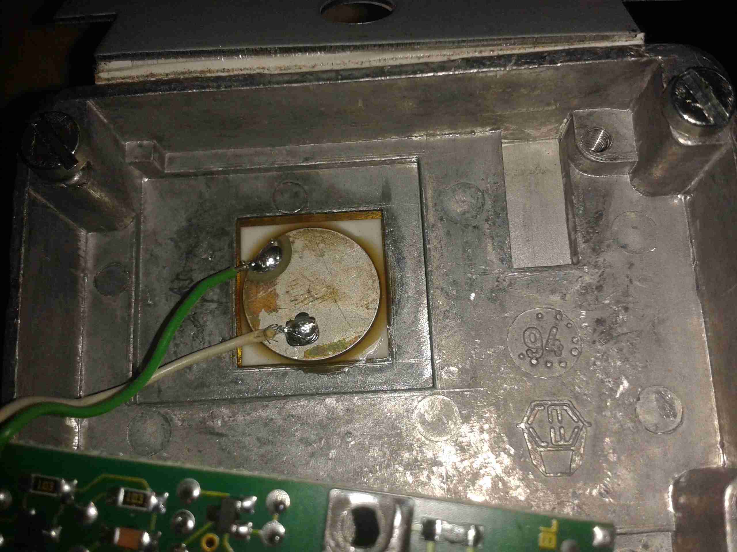
Piezo Sensor
Above is the piezo vibration sensor, bonded to the backplate. When the unit receives vibration or shock, this transducer generates a voltage, which is fed to the control logic below.
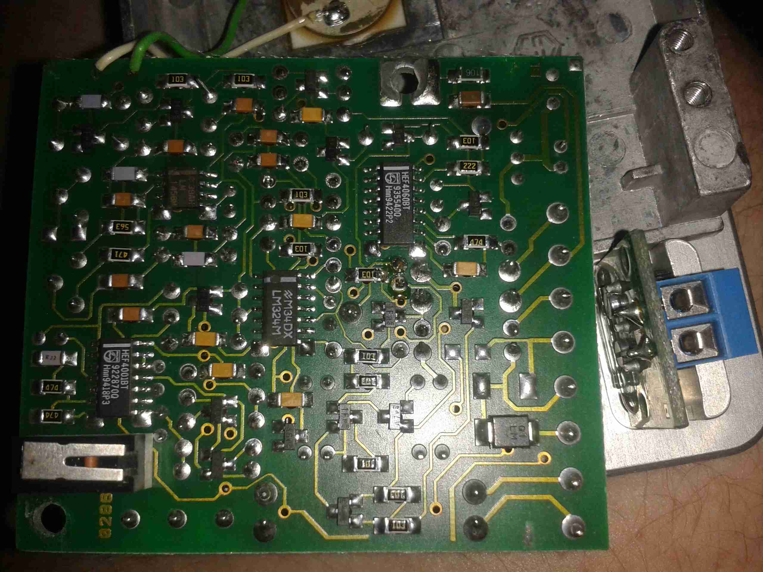
Control Logic
Here’s the reverse of the main PCB with the control logic ICs. These are basic logic gates, with a couple of comparators. One of the tamper switches is in the bottom left corner.
Main PCB
Main PCB with the connection terminals. Another tamper switch is in the top left corner, the solid-state relay is under the shield, next to the magnetic tamper switch. (Reed switch).
Some adjustment is provided for sensitivity. I’ve not found much of a difference in sensitivity though when it’s set to different levels.
Reed Tamper
Magnetic reed switch tamper on the right. Main output solid-state relay on the left under the shield.
This unit was given to me after it apparently went faulty. But on applying power it seems to work fine. Must be those experts again 😉
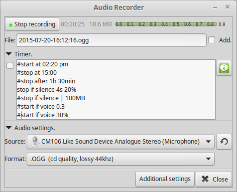
Since my new Wouxun has audio output jacks, I figured it would be useful to have the ability to record what my rig hears, if anything interesting comes on the air.
Under Linux, I use an application called, (creatively enough), Audio Recorder.
Recorder Screenshot
Using a simple connection to the mic input on a USB soundcard, I can capture everything the radio hears. Unfortunately this doesn’t work for outgoing audio, so it’s not much good at capture of my personal QSOs. For this I will have to set up another radio to act as the main receiver.
At some point in the future I will implement this with a Raspberry Pi as the audio capture server.
The latest addition to my radio shack is the GY561 frequency & power meter, which has already come in useful for measuring the output power of all my radios.
GY561
It’s a small device, roughly the same size & weight as a stock UV-5R. Power is provided by 3 AAA cells.
Display
The display is a standard HD44780 8×2 module. The display on this unit isn’t backlit, so no operating in the dark.
Cover Removed
The cover pops off easily to allow access to the internals, without having to remove any screws!
The 4 screws on the back of the unit hold the heatsink plate for the 50W 50Ω dummy load resistor.
Removing the cover reveals a couple of adjustments, for frequency & RF power calibration.
There are also 3 tactile switches that aren’t on the front panel. According to the manual (which in itself is a masterpiece of Chinglish), they are used to software calibrate the unit if an accurate RF power source is available. I will attempt to do a reasonable translation when time allows.
Disassembly further than this involves some desoldering in awkward places, so a search of the internet revealed an image of the rest of the internal components. In the case of my meter, all the part numbers have been scrubbed off the ICs in an attempt to hide their purpose. While it’s possible to cross-reference IC databooks & find the part numbers manually, this process is a time consuming one. Luckily the image I managed to locate doesn’t have the numbers scrubbed.
Total Disassembly
Under the LCD is some 74HC series logic, and a prescaler IC as seen in the previous frequency counter post. However in this unit the prescaler is a MB506 microwave band version to handle the higher frequencies specified.
In this case however the main microcontroller is an ATMEGA8L.
This is complemented by a SN54HC393 4-bit binary counter for the frequency side of things. This seems to make it much more usable down to lower frequencies, although the manual is very generous in this regard, stating that it’s capable of reading down to 1kHz. In practice I’ve found the lowest it reliably reads the frequency input is 10MHz, using my AD9850 DDS VFO Module as a signal source.
It did however read slightly high on all readings with the DDS, but this could have been due to the low power output of the frequency source.
Just like the other frequency counter module, this also uses a trimmer capacitor to adjust the microcontroller’s clock frequency to adjust the calibration.
The power supply circuitry is in the bottom left corner of the board, in this case a small switching supply. The switching regulator is needed to boost the +4.5v of the batteries to +5v for the logic.
Also, as the batteries discharge & their terminal voltage drops, the switching regulator will allow the circuit to carry on functioning. At present I am unsure of the lower battery voltage limit on the meter, but AAA cells are usually considered dead at 0.8v terminal voltage. (2.4v total for the 3 cells).
When turned on this meter draws 52mA from the battery, and assuming 1200mAh capacity for a decent brand-name AAA cell, this should give a battery life of 23 hours continuous use.
On the back of the main PCB is a 5v relay, which seems to be switching an input attenuator for higher power levels, although I only managed to trigger it on the 2m band.
Finally, right at the back attached to an aluminium plate, is the 50Ω dummy load resistor. This component will make up most of the cost of building these, at roughly £15.
On my DVM, this termination reads at about 46Ω, because of the other components on the board are skewing the reading. There are a pair of SMT resistors, at 200Ω & 390Ω in series, and these are connected across the 50Ω RF resistor, giving a total resistance of 46.094Ω.
This isn’t ideal, and the impedance mismatch will probably affect the calibration of the unit somewhat.
The heatsinking provided by the aluminium plate is minimal, and the unit gets noticeably warm within a couple of minutes measuring higher power levels.
High power readings should definitely be limited to very short periods, to prevent overheating.
The RF is sampled from the dummy load with a short piece of Teflon coax.
There’s a rubber duck antenna included, but this is pretty useless unless it’s almost in contact with the transmitting antenna, as there’s no input amplification. It might be handy for detecting RF emissions from power supplies, etc.
For the total cost involved I’m not expecting miracles as far as accuracy is concerned, (the manual states +/-10% on power readings).
The frequency readout does seem to be pretty much spot on though, and the ability to calibrate against a known source is handy if I need some more accuracy in the future.
I’ve also done an SWR test on the dummy load, and the results aren’t good.
At 145.500 MHz, the SWR is 3:1, while at 433.500 it’s closer to 4:1. This is probably due to the lower than 50Ω I measured at the meter’s connector.
These SWR readings also wander around somewhat as the load resistor warms up under power.
I’ll probably also replace the AAA cells with a LiPo cell & associated charge/protection circuitry, to make the unit chargeable via USB. Avoiding disposable batteries is the goal.
I’ve noticed that the RF power output from the Chinese radios can be quite variable from model to model, and even from individual radios of the same model & batch.
I’ve bought an RF Power meter (GY561) to do some tests on the HTs I have at present.
All tests were performed with the radio fully charged & still on the charging base, to make sure the supply voltage remained constant at 8.4v throughout the tests.
Frequencies used were 145.500 & 433.500 for VHF & UHF respectively.
The power meter was connected with ~8″ of RG174 Coax.
Recently I decommissioned some networking equipment, and discovered the power supplies in some switches were single rail 12v types, with a rather high power rating. I figured these would be very good for powering my Ham radio gear.
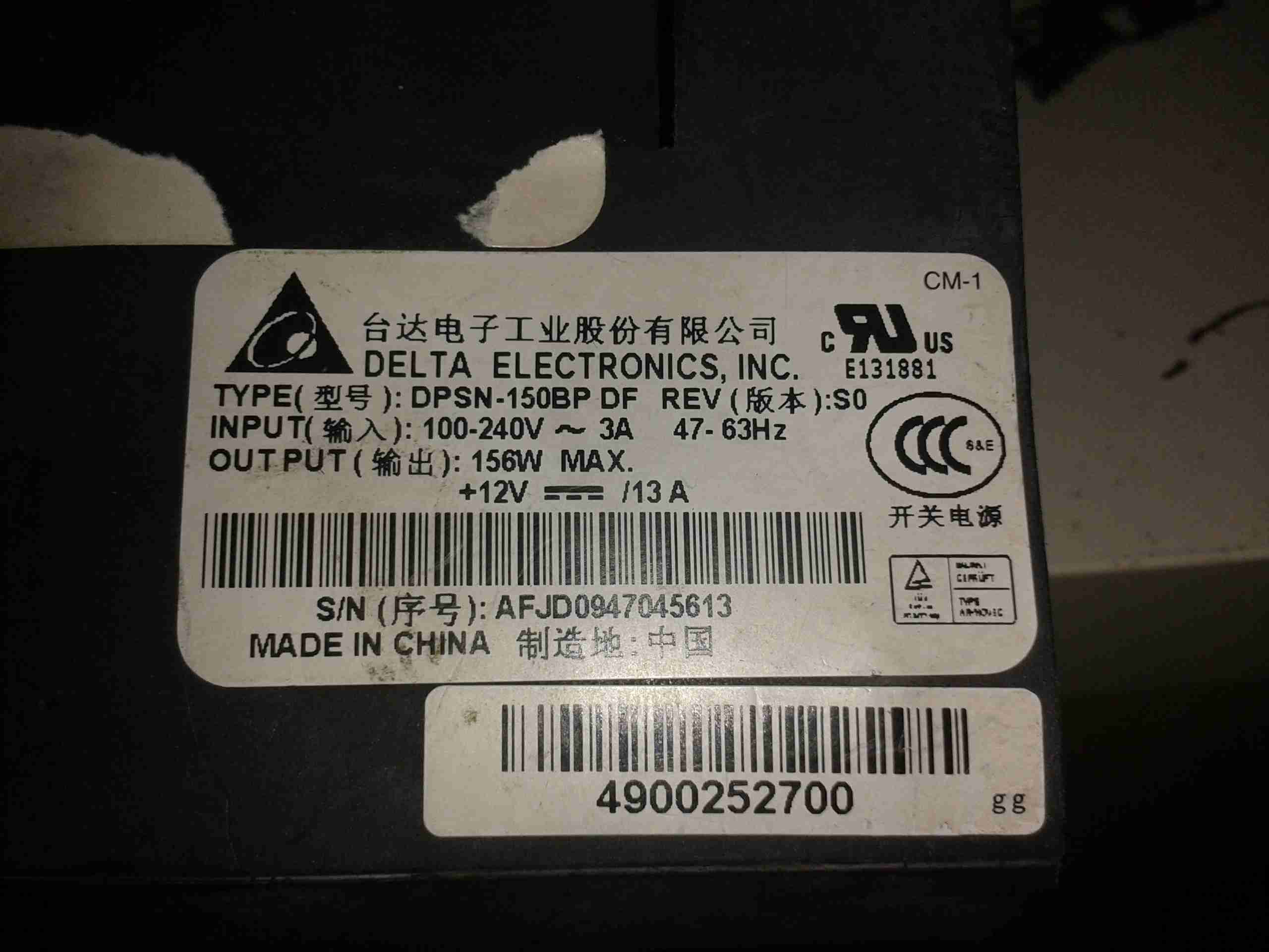
They’re high quality Delta Electronics DPSN-150BP units, rated at a maximum power output of 156W.
Label
These supplies have an adjustment pot for the output voltage regulation, but unfortunately it just didn’t have quite enough range to get from 12.0v to 13.8v. The highest they would go was ~13.04v.
After taking a look at the regulator circuit, I discovered I could further adjust the output voltage by changing a single resistor to a slightly lower value.
Firstly though, a little background on how switched mode power supplies operate & regulate their output voltage.
SMPS
Here’s the supply. It’s mostly heatsink, to cool the large power switching transistors.
The first thing a SMPS does, is to rectify the incoming mains AC with a bridge rectifier. This is then smoothed by a large electrolytic capacitor, to provide a main DC rail of +340v DC (when on a 240v AC supply).
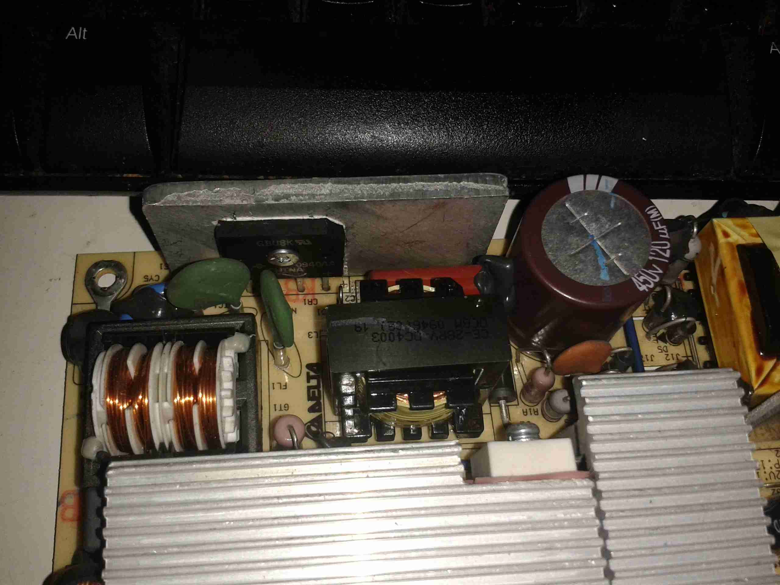
Mains Input
Above is the mains input section of the PSU, with a large common-mode choke on the left, bridge rectifier in the centre, and the large filter capacitor on the right. These can store a lot of energy when disconnected from the mains, and while they should have a discharge resistor fitted to safely drain the stored energy, they aren’t to be relied on for safety!
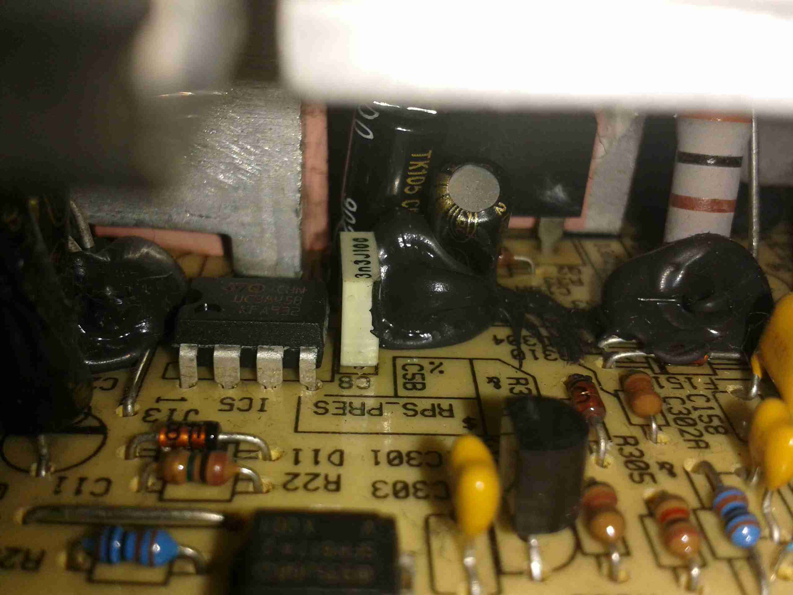
Once the supply has it’s main high voltage DC rail, this is switched into the main transformer by a pair of very large transistors – these are hidden from view on the large silver heatsinks at the bottom of the image. These transistors are themselves driven with a control IC, in the case of this supply, it’s a UC3844B. This IC is hidden under the large heatsink, but is just visible in the below photo. (IC5).
Control ICMain Switching Transformer
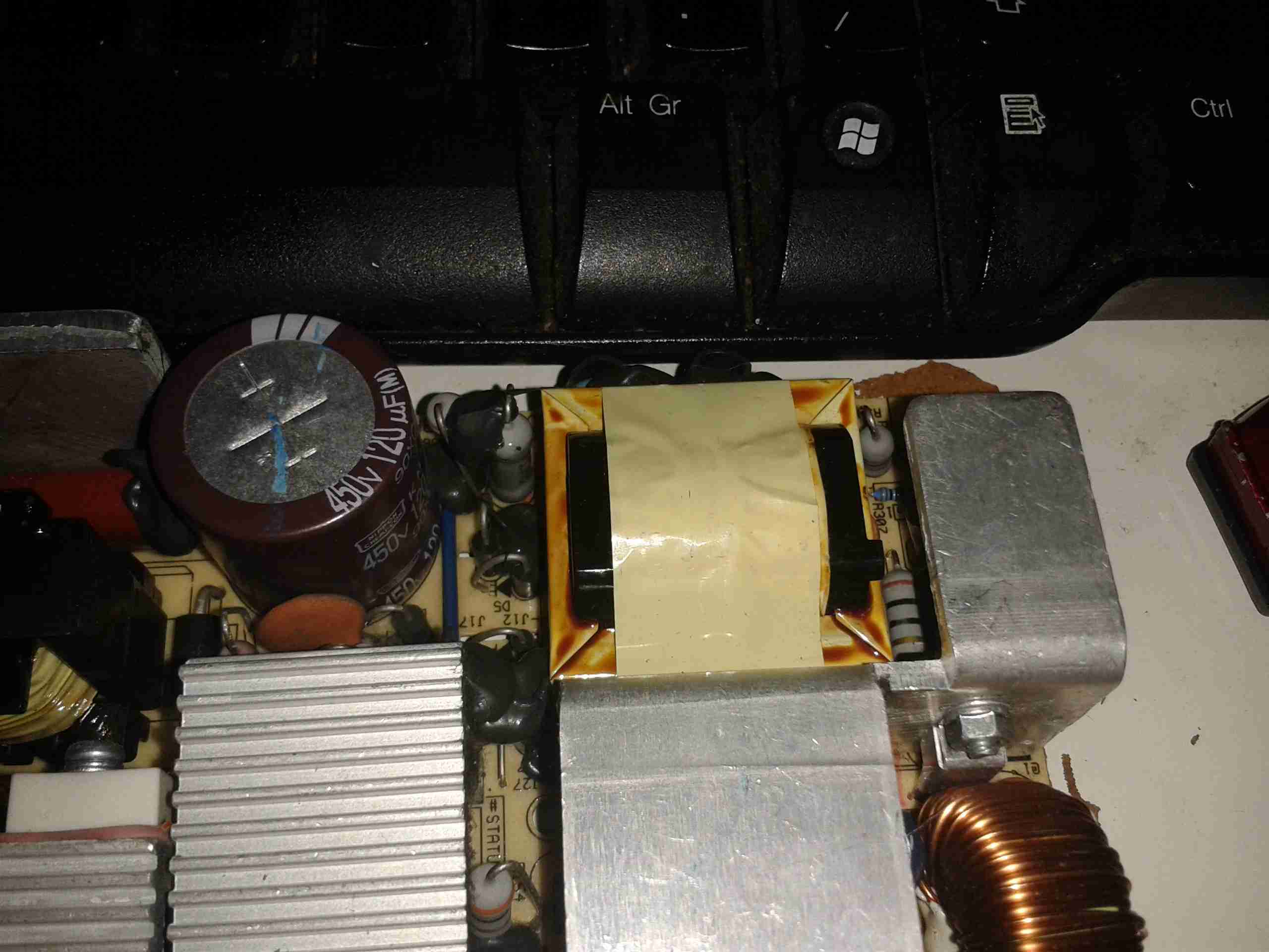
Here’s the main switching transformer, these can be much smaller than a conventional transformer due to the high frequencies used. This supply operates at 500kHz.
After the main transformer, the output is rectified by a pair of Schottky diodes, which are attached to the smaller heatsink visible below the transformer, before being fed through a large toroidal inductor & the output filter capacitors.
All this filtering on both the input & the output is required to stop these supplies from radiating their operating frequency as RF – a lot of cheap Chinese switching supplies forego this filtering & as a result are extremely noisy.
After all this filtering the DC appears at the output as usable power.
Getting back to regulation, these supplies read the voltage with a resistor divider & feed it back to the mains side control IC, through an opto-isolator. (Below).
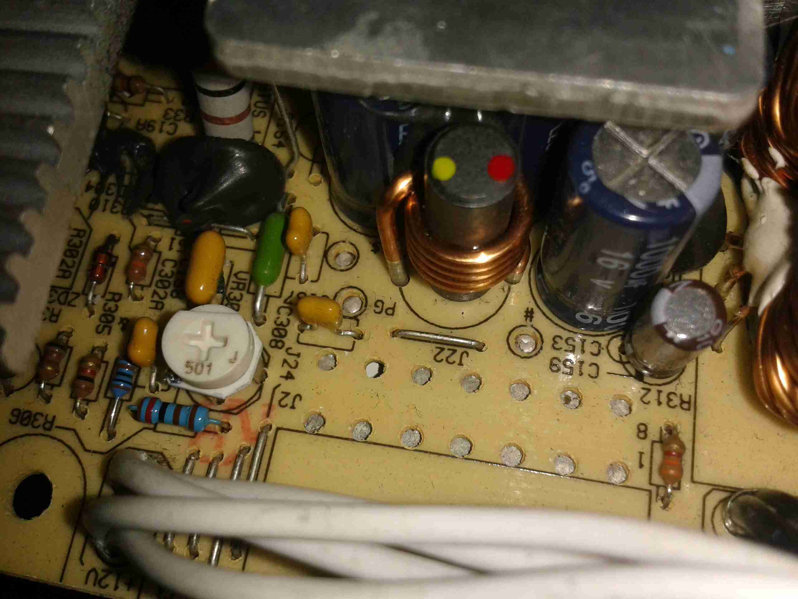
Feedback Loop
The opto isolators are the black devices at the front with 4 pins.
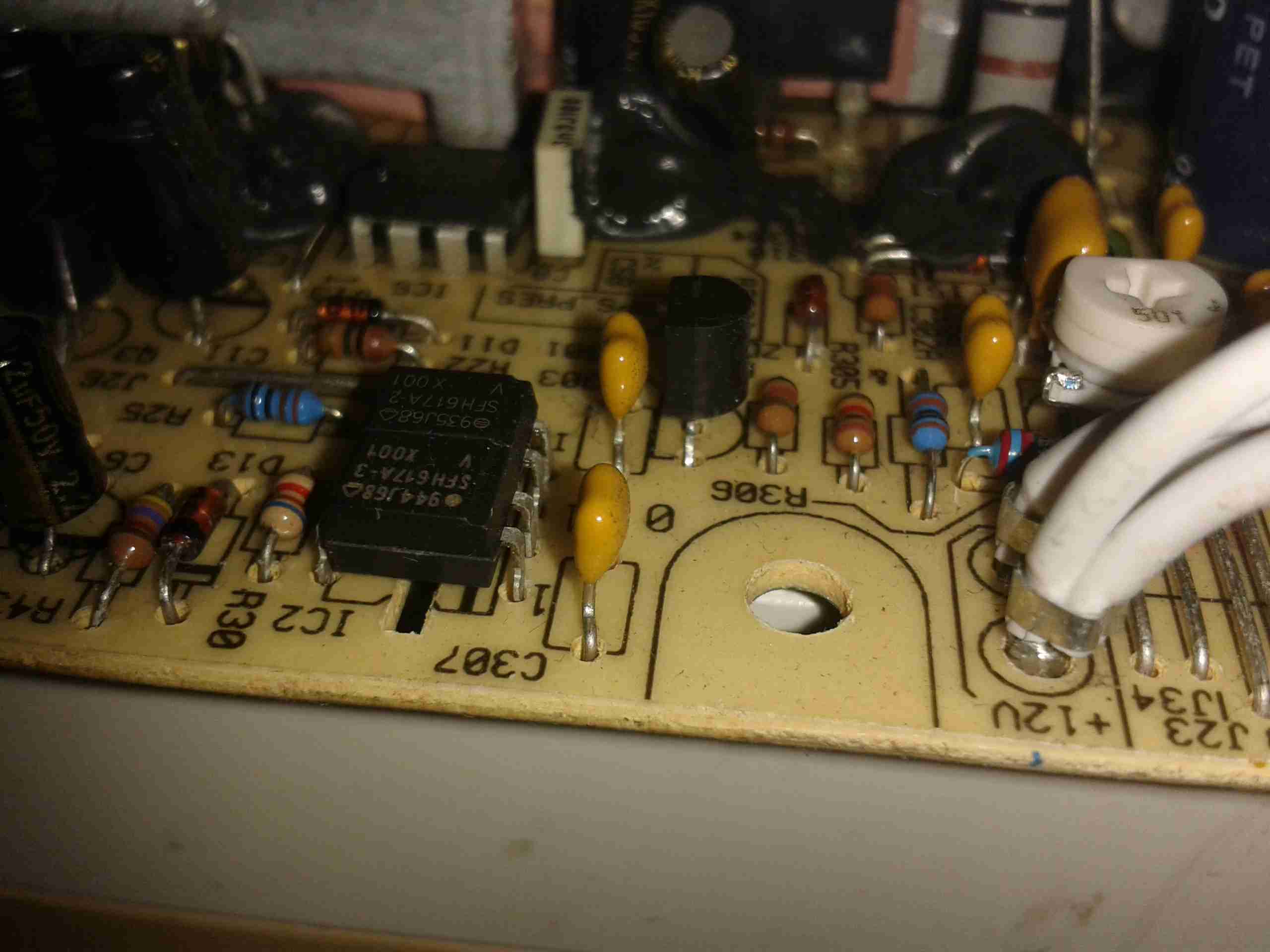
Regulator Adjustment
For a more in-depth look at the inner workings of SMPS units, there’s a good article over on Hardware Secrets.
My modification is simple. Replacing R306 (just below the white potentiometer in the photo), with a slightly smaller resistor value, of 2.2KΩ down from 2.37KΩ, allows the voltage to be pulled lower on the regulator. This fools the unit into applying more drive to the main transformer, and the output voltage rises.
It’s important to note that making too drastic a change to these supplies is likely to result in the output filter capacitors turning into grenades due to overvoltage. The very small change in value only allows the voltage to rise to 13.95v max on the adjuster. This is well within the rating of 16v on the output caps.
Now the voltage has been sucessfully modified, a new case is on the way to shield fingers from the mains. With the addition of a couple of panel meters & output terminals, these supplies will make great additions to my shack.
After watching a video over at Scullcom Hobby Electronics on YouTube, I figured I’d build one of these precision references to calibrate my multimeters.
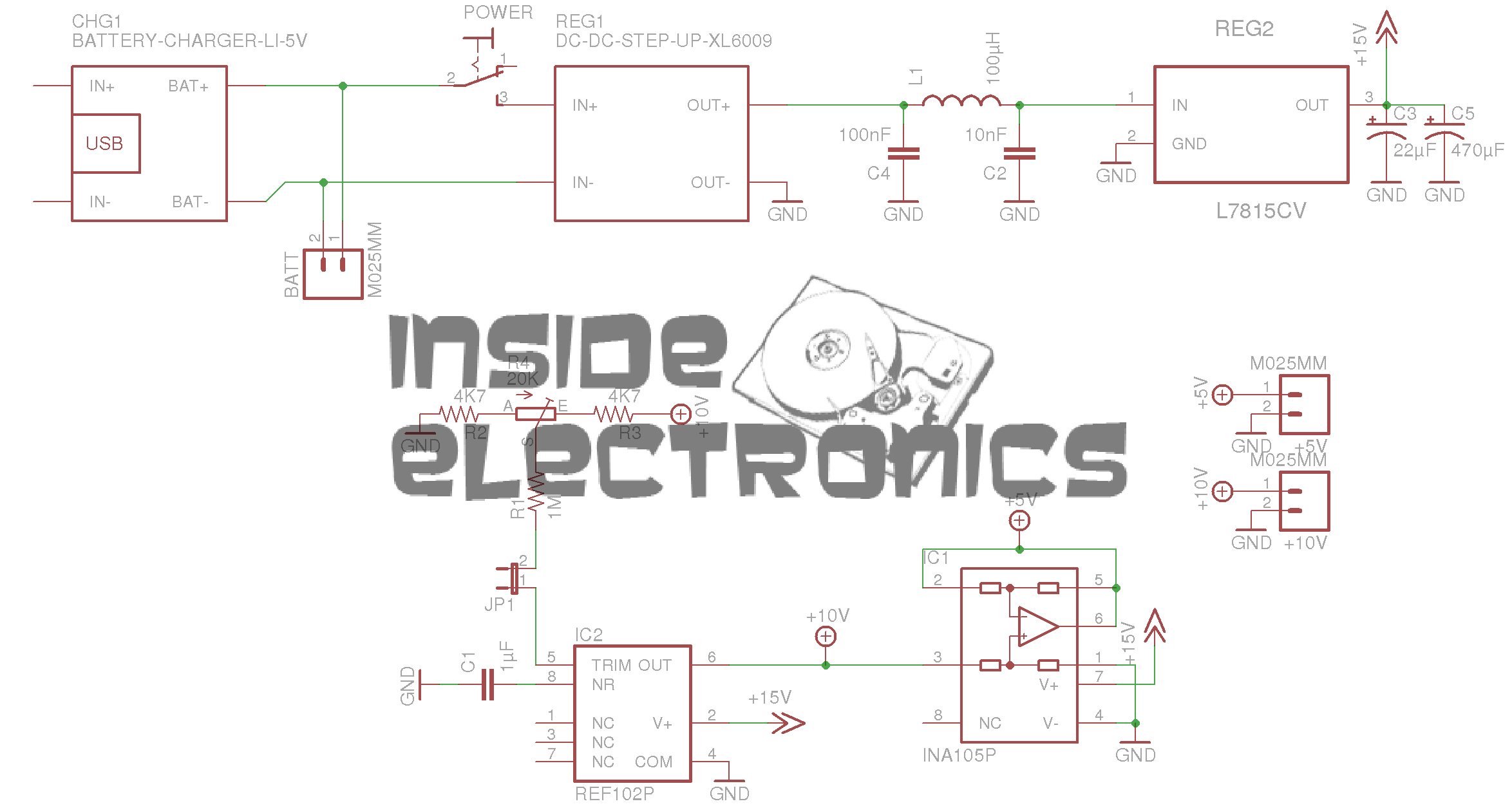
It’s based around a REF102P 10v precision reference & an INA105P precision unity gain differential amplifier.
For full information, check out the video, I won’t go into the details here, just my particular circuit & PCB layout.
In the video, Veroboard is used. I’m not too fond of the stuff personally. I find it far too easy to make mistakes & it never quite looks good enough. To this end I have spun a board in Eagle, as usual.
Precision Ref SCH – Click to Embiggen
Here’s the schematic layout, the same as is in the video.
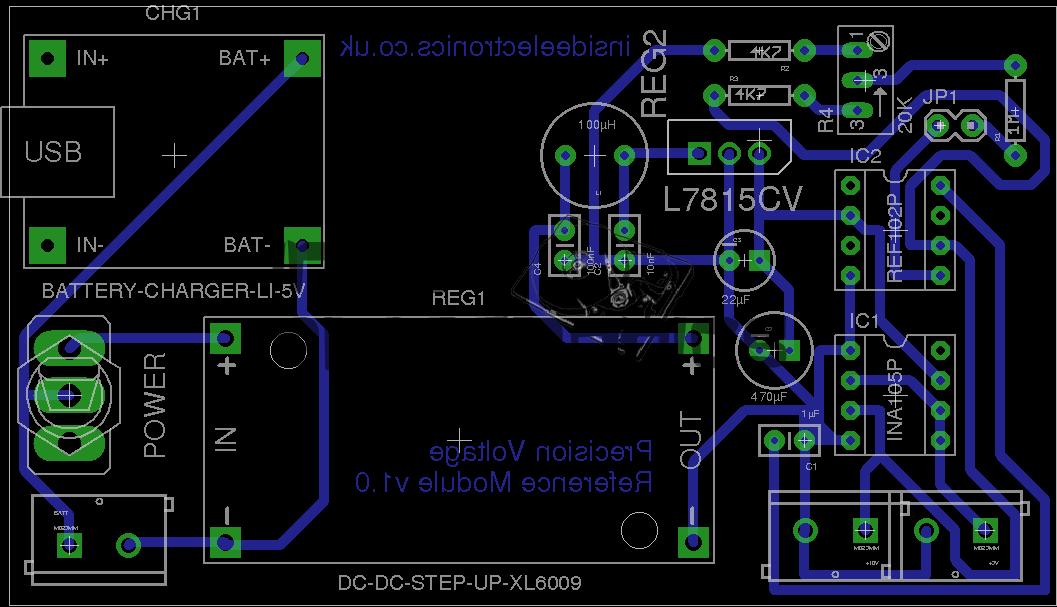
Precision Ref BRD
As usual, the Eagle CAD layout files can be found at the bottom of the post.
And the associated PCB layout. I have added the option to be able to tweak the output, to get a more accurate calibration, which can be added by connecting JP1 on the PCB.
As in the original build, this unit uses pre-built DC-DC converter & Li-Ion charger modules. A handy Eagle library can be found online for these parts.
I have however left off the battery monitor section of the circuit, since I plan to use a protected lithium cell for power. This also allowed me to keep the board size down, & use a single sided layout.
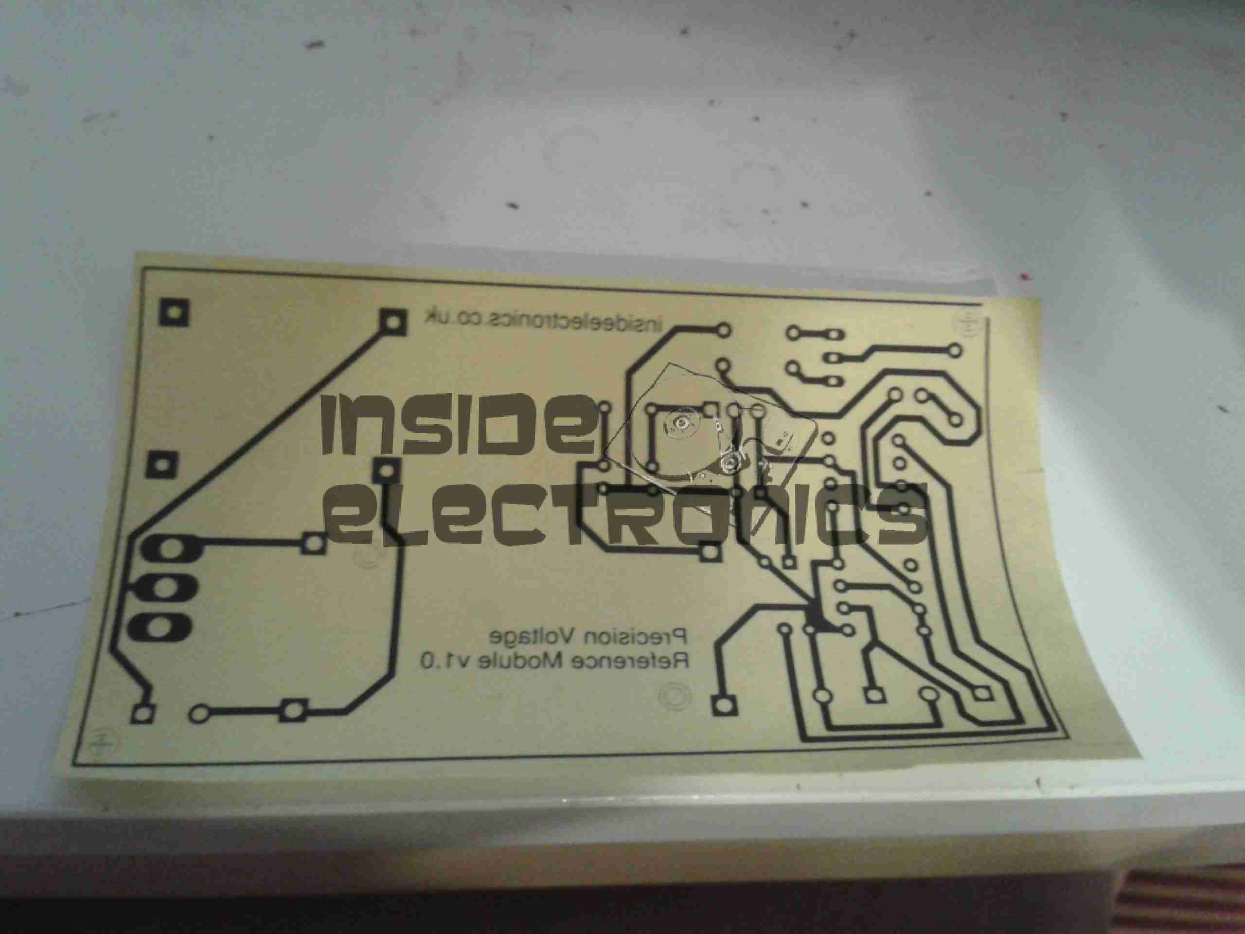
Toner Transfer Paper
Here’s the track layout ready to iron onto the copper clad board. I use the popular toner transfer system with special paper from eBay, this stuff has a coating that allows the toner to easily be transferred to the PCB without having to mess about with soaking in water & scraping paper off.
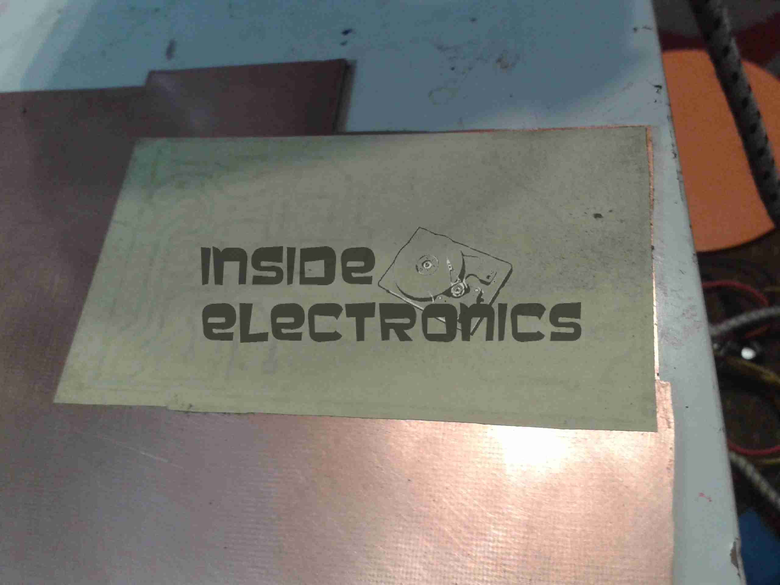
Ironed On
Here’s the paper having just been ironed onto the copper. After waiting for the board to cool off the paper is peeled off, leaving just the toner on the PCB.
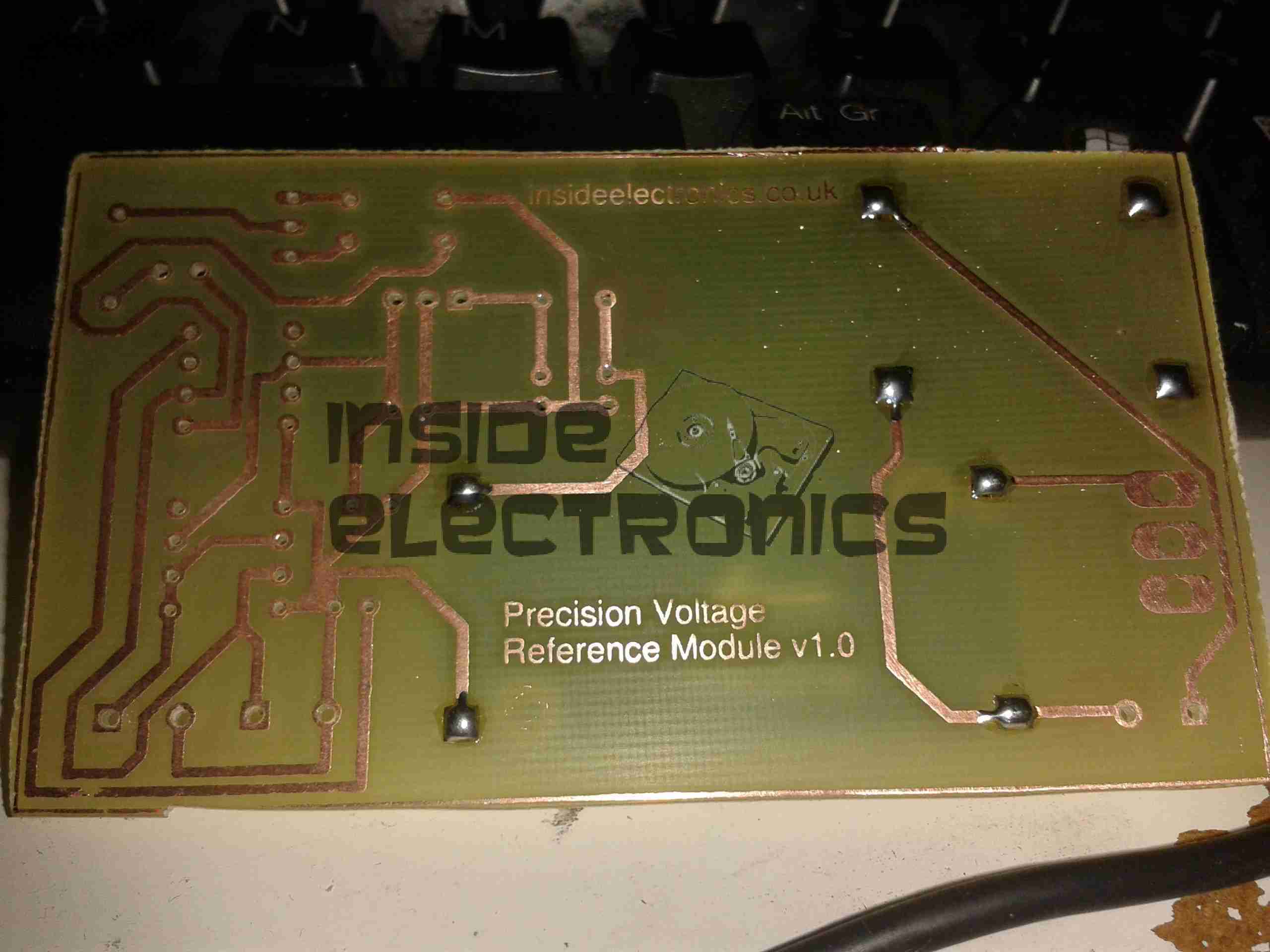
Etched PCB
PCB just out of the etch tank, drilled & with the solder pins for the modules installed. Only one issue with the transfer, in the bottom left corner of the board is visible, a very small section of copper was over etched.
This is easily fixed with a small piece of wire.
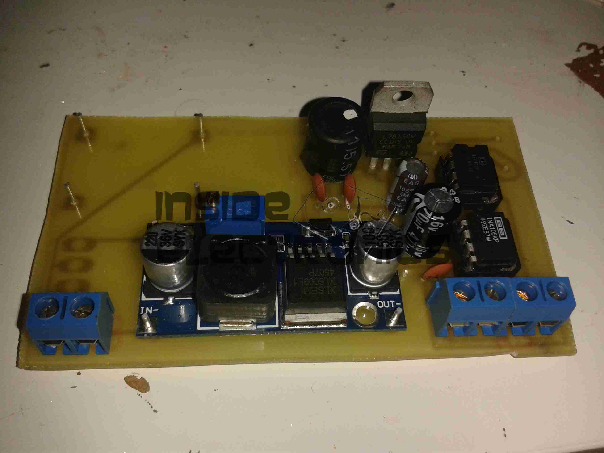
Components Populated
Main components populated. The DC-DC converter is set at 24v output, which the linear regulator then drops down to the +15v rail for the reference IC. The linear section of the regulator, along with the LC filter on the output of the switching regulator produce a low-ripple supply.
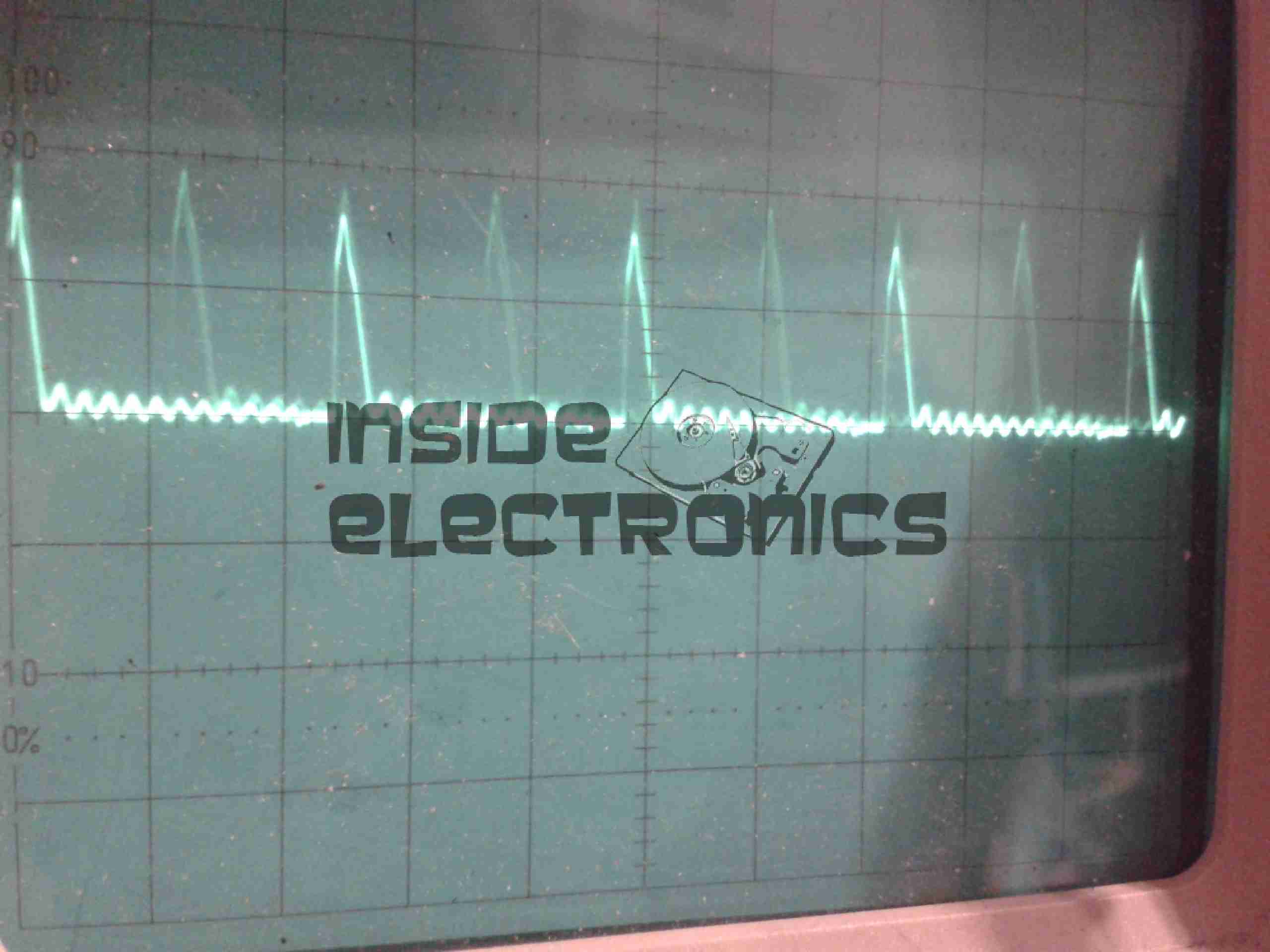
SMPS Ripple
Here’s the scope reading the AC ripple on the output of the DC-DC converter. Scale is 100mV/Div. Roughly 150mV of ripple is riding on top of the DC rail.
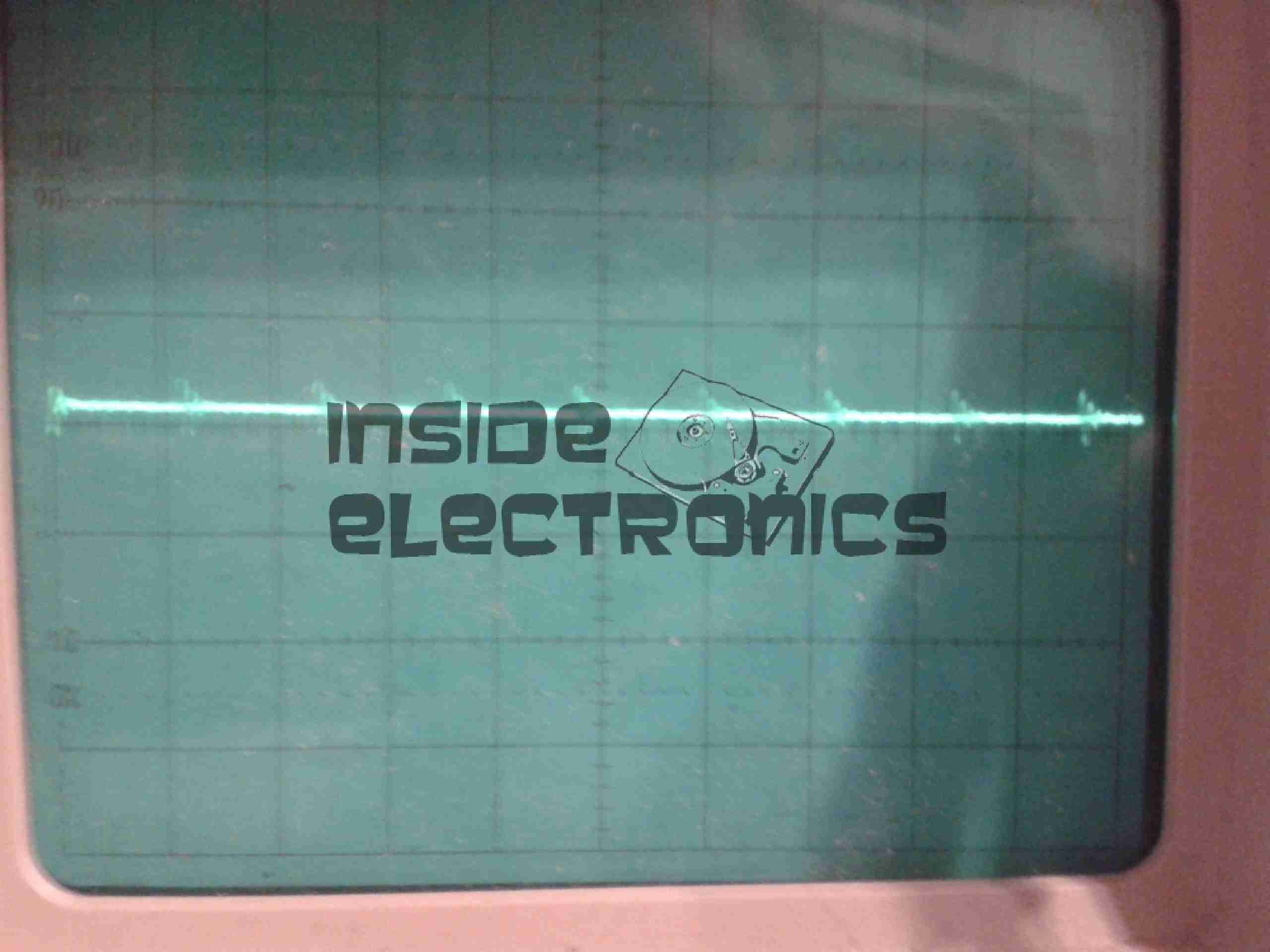
Linear PSU Ripple
And here’s the output from the linear regulator, scale of 50mV/Div. Ripple has been reduced to ~15mV for the reference IC.
In total the circuit as built has a power consumption of ~0.5W, most of which is being dissipated as heat in the linear part of the PSU.
I’ve been doing some tinkering with the RN-52 Bluetooth Audio module from Roving Networks, in prep for building a portable wireless speaker system, & thought I’d share my designs.
Initially I was having some issues with RF noise on the audio output from the RN-52, as I was only using the outputs single-ended. The module didn’t like this treatment, with all the RF whine coming straight out of the speakers.
To fix this issue I have used a pair of jellybean LM386 audio power amplifiers, running in differential input mode. This solves the high-pitched whine when the audio is enabled, & also allows the module to directly drive a set of 32Ω headphones at a reasonable level.
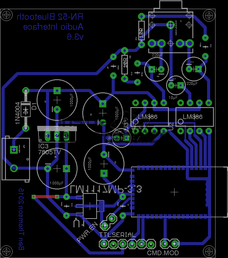
In Eagle I have designed a simple board, routing only the audio output, serial TTL & command mode pins out, along with the supporting power supply circuitry to operate from 12v DC.
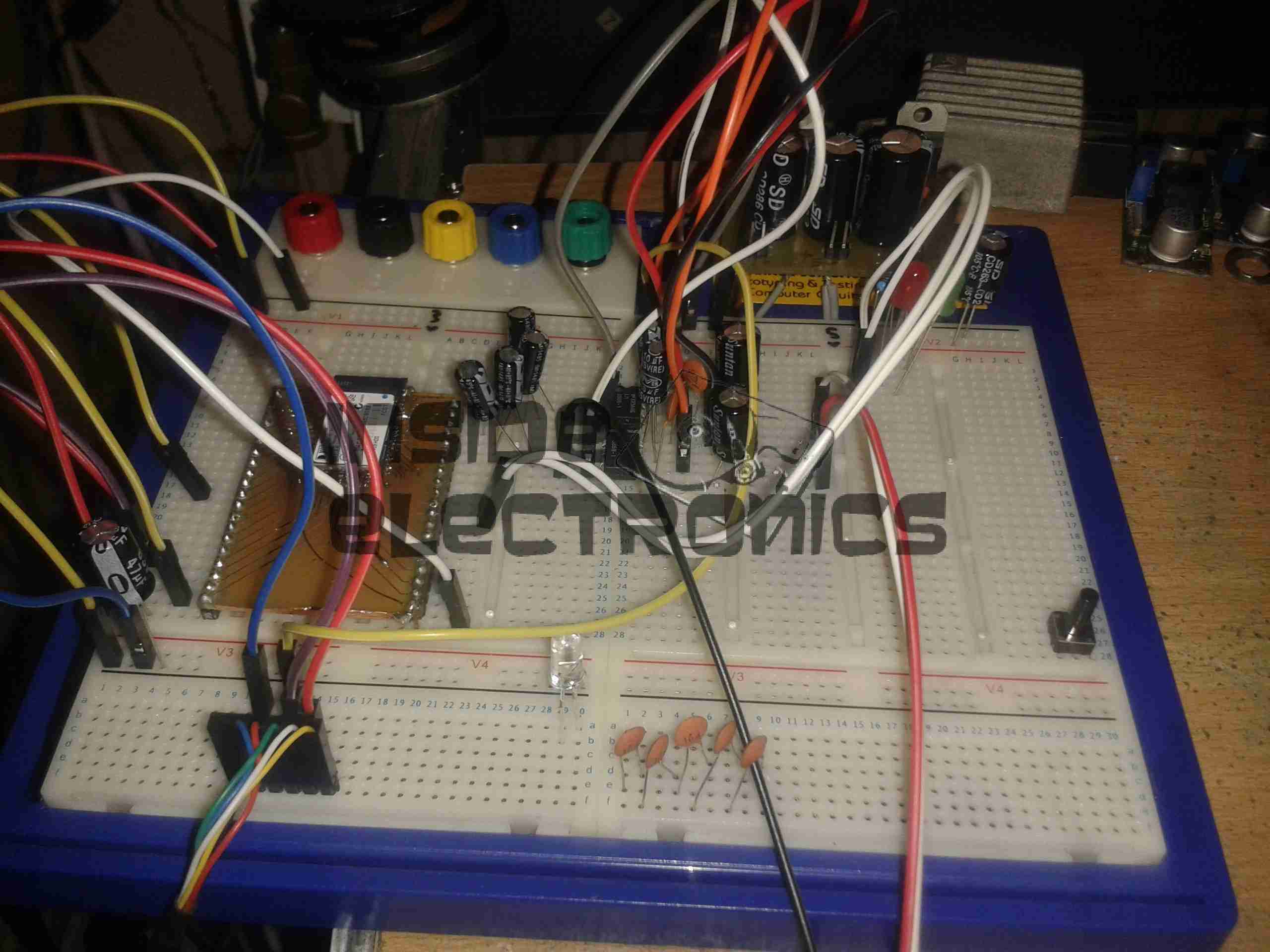
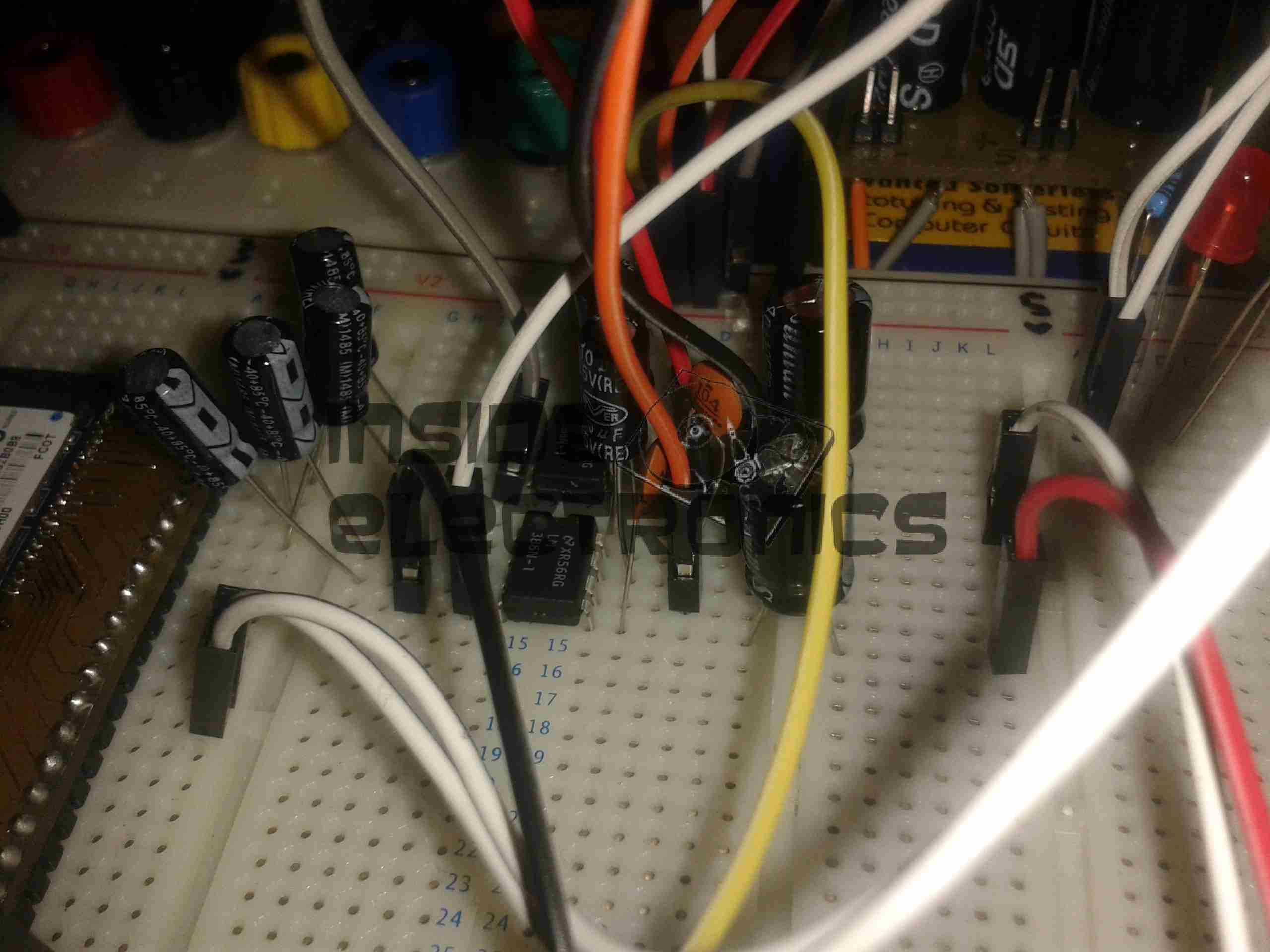
RN-52 Breadboard
Above is the current incarnation of the circuit on the breadboard. The RN-52 is on the left, audio power stage in the centre & headphone output on the right.
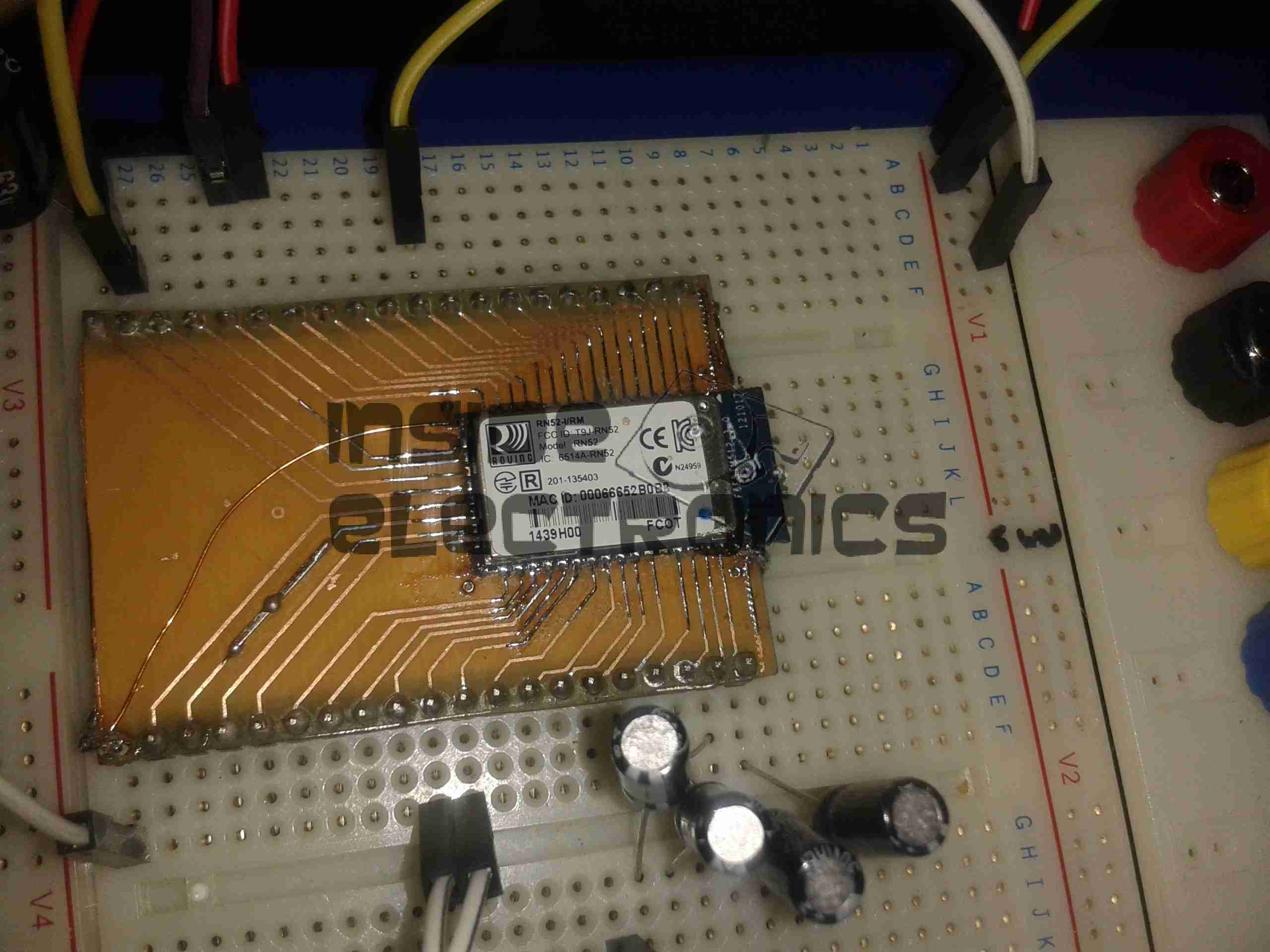
RN-52 Breakout
The bluetooth module on a breakout board. I was cheap in this case & etched my own board. I’m not paying Sparkfun, (as much as I like them), an extra ~£10 for a small PCB with the pins broken out. Much cheaper to spend 15 minutes with the laser printer & the iron, & do a toner transfer PCB.
As this board is single sided, I added a ground plane on the underside with copper foil, to help with the RF issues. Breadboards really aren’t all that good at rejecting noise induced when there’s a 2.4GHz transceiver mounted on them.
LM386 Amplifier
The LM386 audio power stage. The differential inputs from the module are capacitively coupled with 1µF electrolytics. This setup remarkably reduced the noise on the output. I left these at their default gain of 20, as I’ll be connecting another high power amplifier stage to drive large speakers.
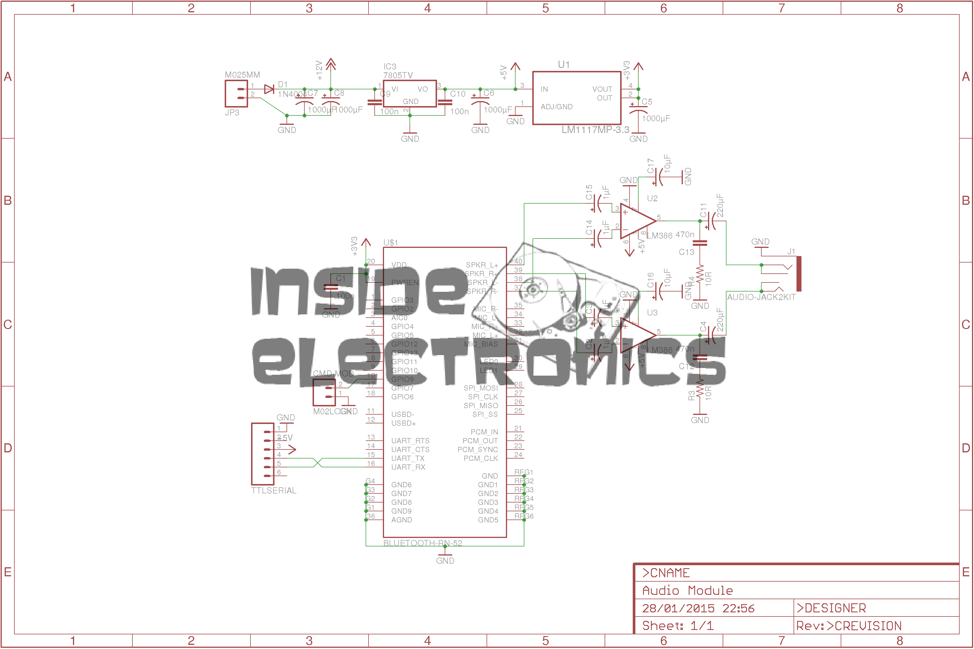
RN-52 Eagle Layout
Here’s the circuit laid out in Eagle, ready for PCB.
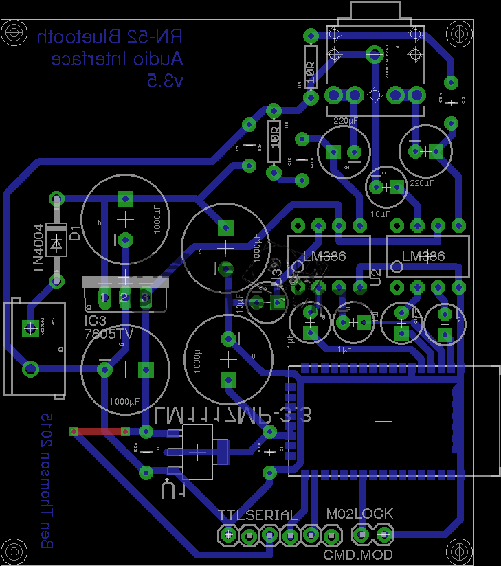
RN-52 Eagle PCB
And here’s the PCB layout. Only one link required for the +5v line from the TTL serial port.
As always, the Eagle PCB & Schematic layout files are available at the bottom of the article.
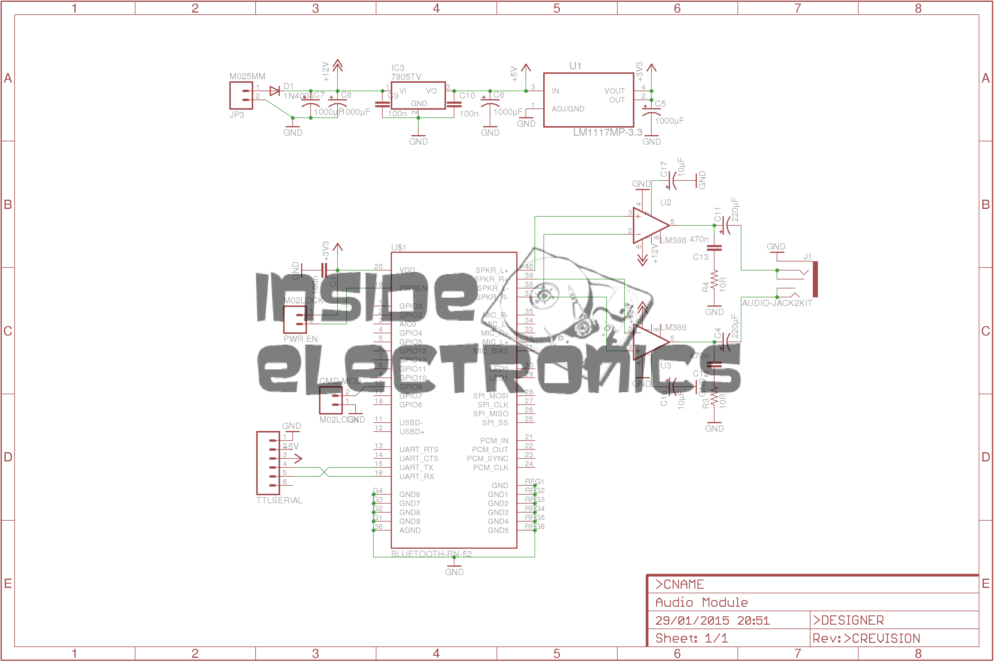
*Update 29-01-15*
Rerouted a few things:
Moved the audio power stage to the +12v rail to improve sound response. – As the LM386 has a max input voltage of 12v (absolute maximum 15v), a regulated supply is recommended. The LM386-N4 variant has a higher voltage range, up to 18v. This should be suitable for an unregulated supply.
Removed 1µF coupling capacitors to reduce distortion & amplifier hiss. The capacitors appeared to cause some instability on the amplifier, causing random distortion. Removing them has cured this. No signal hiss has also been reduced to a very low level.
Reversed input polarity on input of one of the amplifiers – this appears to produce better audio.
Added PWR.EN header to allow connection of power button. Saves hassle of cycling power to the board when the RN-52 goes into sleep mode.
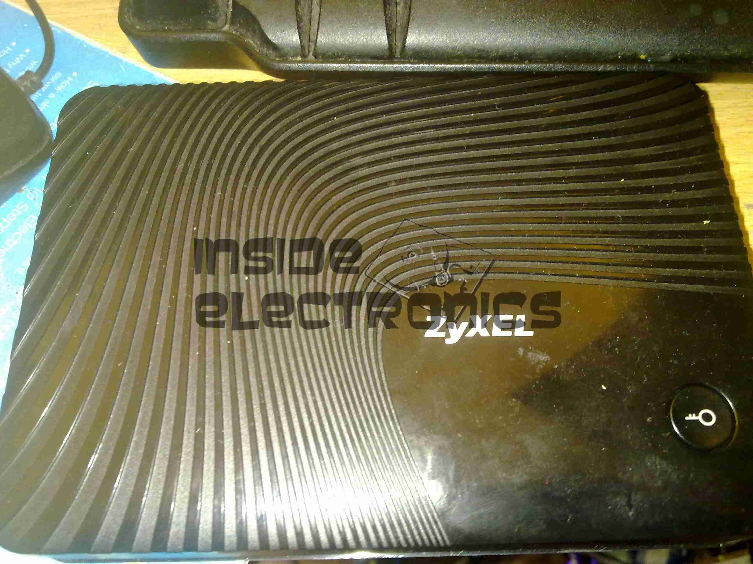
Here is a ZyXel WAP3205 WiFi Access Point that has suffered a reverse polarity event, due to an incorrect power supply being used with the unit.
ZyXEL WAP3205
While most electronic gadgets are protected against reverse polarity with a blocking diode, this unit certainly wasn’t. Applying +12v DC the wrong way round resulted in this:
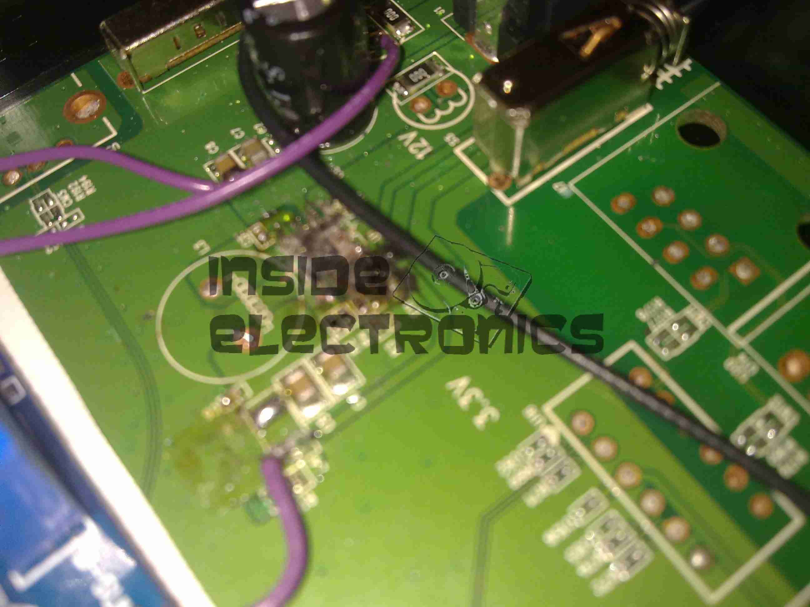
Blown Switchmode IC (Fuzzy Focus)
That is the remains of the 3.3v regulator IC, blown to smithereens & it even attempted an arson attack. Luckily this was the only damaged component, & I was able to repair the unit by replacing the switching IC with a standalone regulator. (Replacing the IC would have been preferable, if there was anything left of it to obtain a part number from).
I scraped away the pins of the IC to clear the short on the input supply, removed the switching inductor, & tacked on an adjustable regulator module set to 3.3v. Luckily the voltage of the supply is handily marked on the PCB next to the circuit.
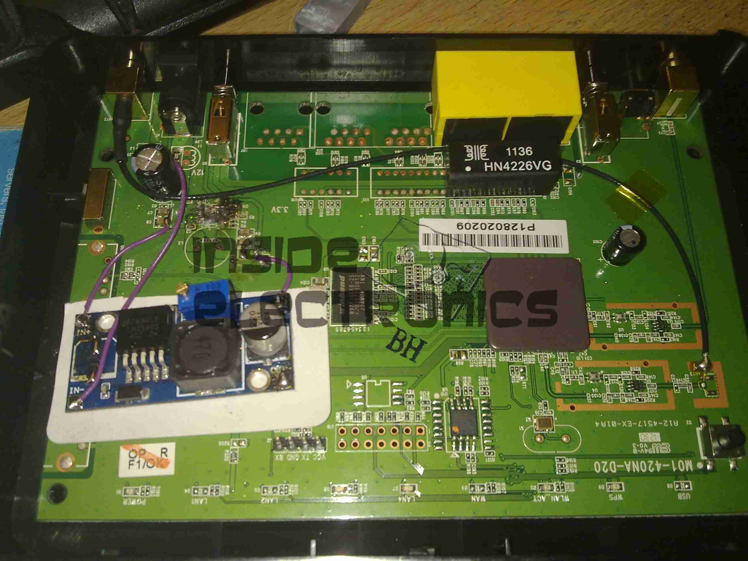
Replacement PSU
Replacement SMPS in place on top of the PCB. The output of the supply is connected to one of the pads of L4 (on my unit just an 0 ohm link), the +12v input is connected to the + rail side of C8 & C7 & the final ground connection is hooked in to the back of the barrel jack.
After this replacement, the unit booted straight up as if nothing had happened. All the logic is undamaged!
Continuing from my previous post where I published an Eagle design layout for AD7C‘s Arduino powered VFO, here is a completed board.
I have made some alterations to the design since posting, which are reflected in the artwork download in that post, mainly due to Eagle having a slight psychotic episode making me ground one of the display control signals!
AD9850 VFO
The amplifier section is unpopulated & bypassed as I was getting some bad distortion effects from that section, some more work is needed there.
The Arduino Pro Mini is situated under the display, and the 5v rail is provided by the LM7805 on the lower left corner.
Current draw at 12v input is 150mA, for a power of 1.8W total. About 1W of this is dissipated in the LM7805 regulator, so I have also done a layout with an LM2574 Switching Regulator.
The SMPS version should draw a lot let power, as less is being dissipated in the power supply, but this version is more complex.
DDS VFO-SMPS
Here the SMPS circuit can be seen on the left hand side of the board, completely replacing the linear regulator.
I have not yet built this design, so I don’t know what kind of effect this will have on the output signal, versus the linear regulator. I have a feeling that the switching frequency of the LM2574 (52kHz) might produce some interference on the output of the DDS module. However I have designed this section to the standards in the datasheet, so this should be minimal.
Nevertheless this version is included in the Downloads section at the bottom of this post.
The output coupled through a 100nF capacitor is very clean, as can be seen below, outputting a 1kHz signal. Oscilloscope scale is 0.5ms/div & 1V/div.
VFO Output (Mucky ‘Scope)Scope Connected
Thanks again to Rich over at AD7C for the very useful tool design!
Linked below is the Eagle design files for this project, along with my libraries used to create it.
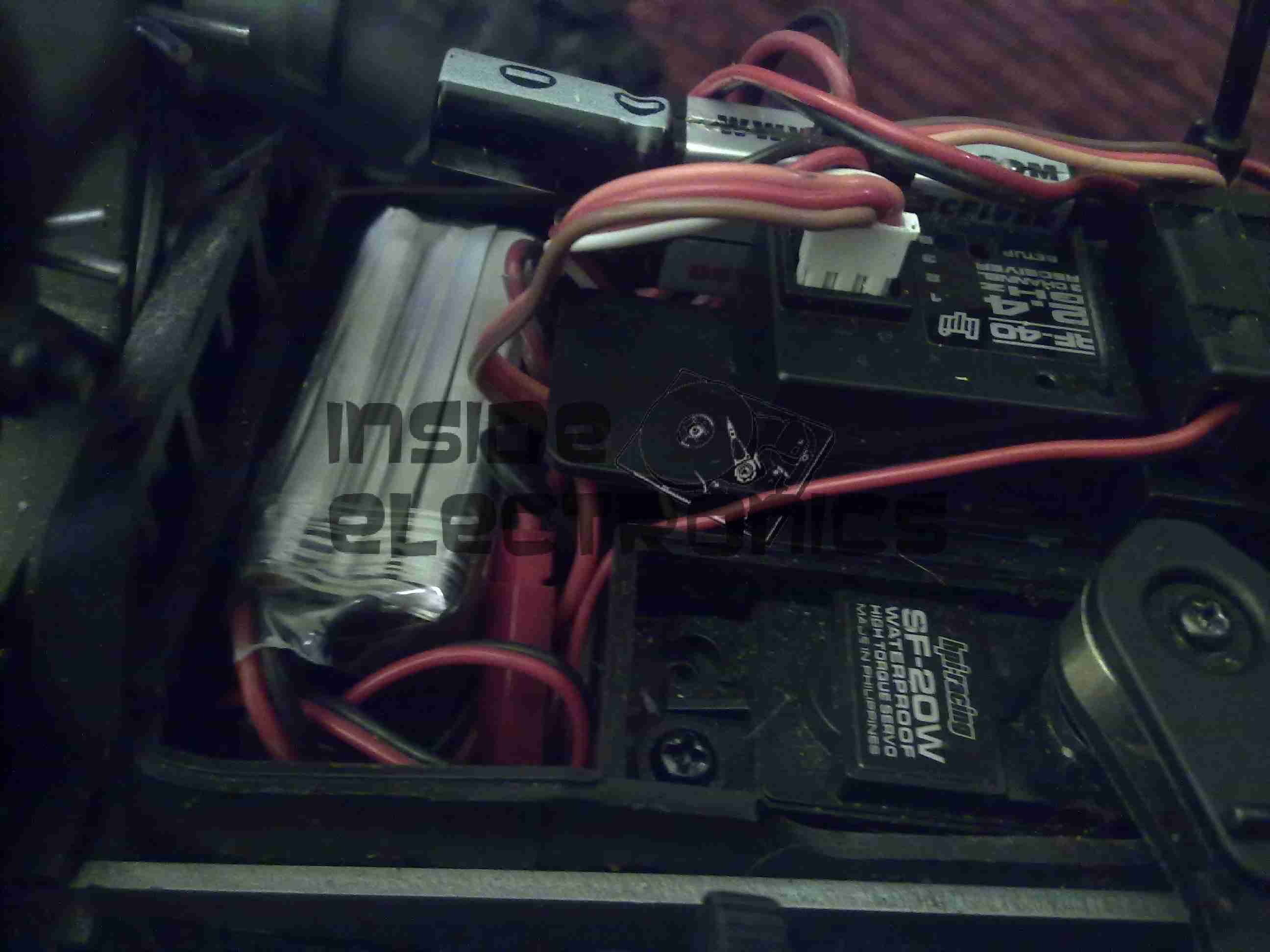
To provide more run time with the conversion to petrol & spark ignition, I have also upgraded the on-board electronics supply to compensate for the extra ~650mA draw of the ignition module.
This modification is centred around a 3S Lithium-Polymer battery pack, providing a nominal 11.1v to a voltage regulator, which steps down this higher voltage to the ~6v required by the receiver & servo electronics.
Power RegulatorPower Regulator
The regulator, shown above, is a Texas Instruments PTN78060WAZ wide-input voltage adjustable regulator. This module has an exceptionally high efficiency of ~96% at it’s full output current of 3A. The output voltage is set by a precision resistor, soldered to the back of the module, in this case 6.5v. Standard RC connectors are used on the regulator to allow connection between the power switch & the radio receiver.
Receiver Box
Everything tucked away into place inside the receiver box. The 3S 1000mAh LiPo fits perfectly in the space where the original Ni-Mh hump pack was located.
The completely stable output voltage of the regulator over the discharge curve of the new battery gives a much more stable supply to the radio & ignition, so I should experience fewer dropouts. Plus the fact that the engine now relies on power from the receiver pack to run, it’s a built in fail safe – if the power dies to the receiver, the engine also cuts out.
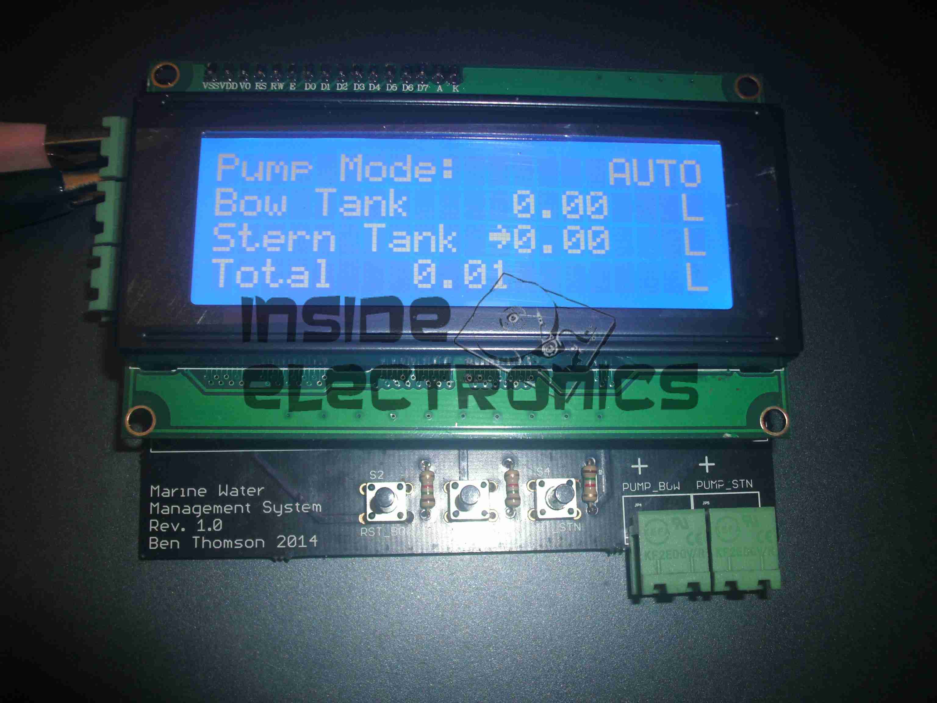
Having two separate water tanks on nb Tanya Louise, with individual pumps, meant that monitoring water levels in tanks & keeping them topped up without emptying & having to reprime pumps every time was a hassle.
To this end I have designed & built this device, to monitor water usage from the individual tanks & automatically switch over when the tank in use nears empty, alerting the user in the process so the empty tanks can be refilled.
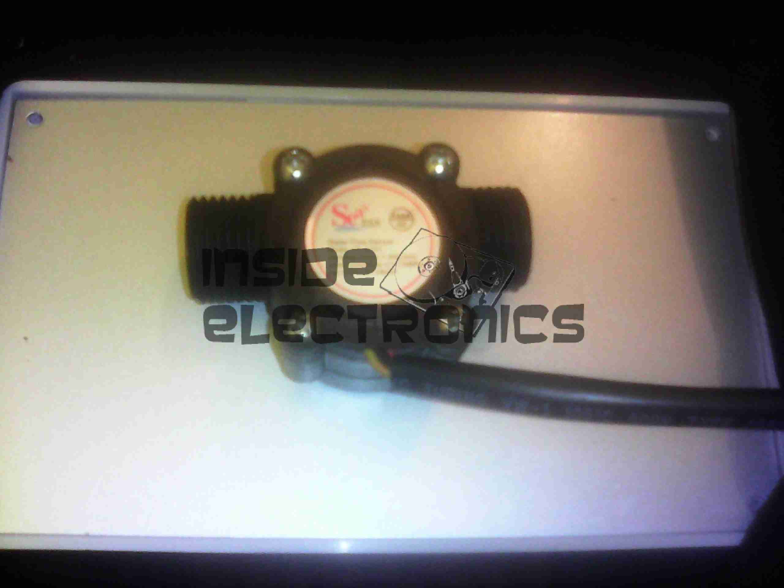
Based around an ATMega328, the unit reads a pair of sensors, fitted into the suction line of each pump from the tanks. The calculated flow is displayed on the 20×4 LCD, & logged to EEPROM, in case of power failure.
Water Flow Sensor
When the tank in use reaches a preset number of litres flowed, (currently hardcoded, but user input will be implemented soon), the pump is disabled & the other tank pump is enabled. This is also indicated on the display by the arrow to the left of the flow register. Tank switching is alerted by the built in beeper.
It is also possible to manually select a tank to use, & disable automatic operation.
Resetting the individual tank registers is done by a pair of pushbuttons, the total flow register is non-resettable, unless a hard reset is performed to clear the onboard EEPROM.
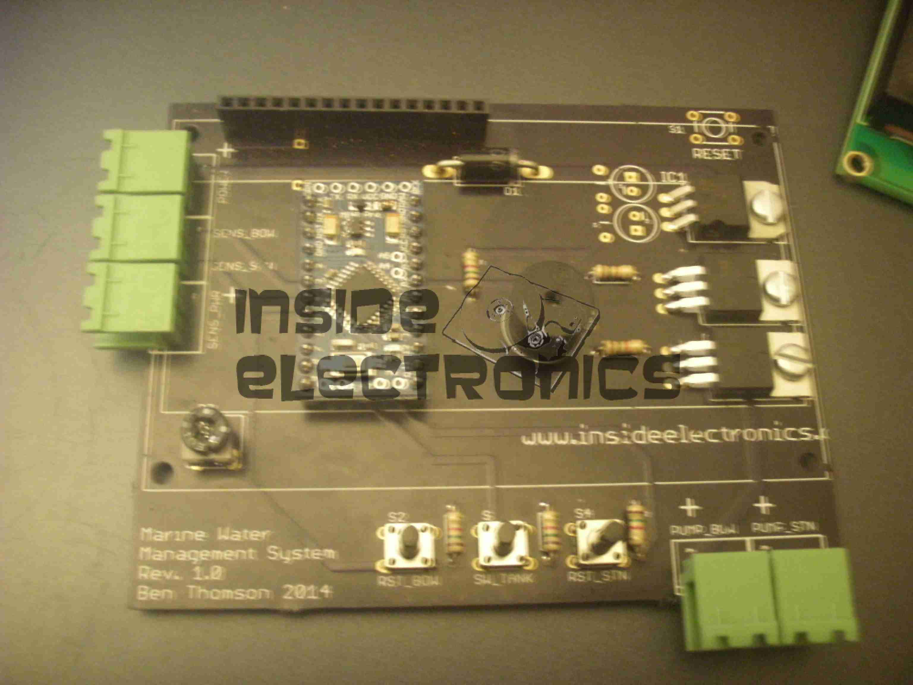
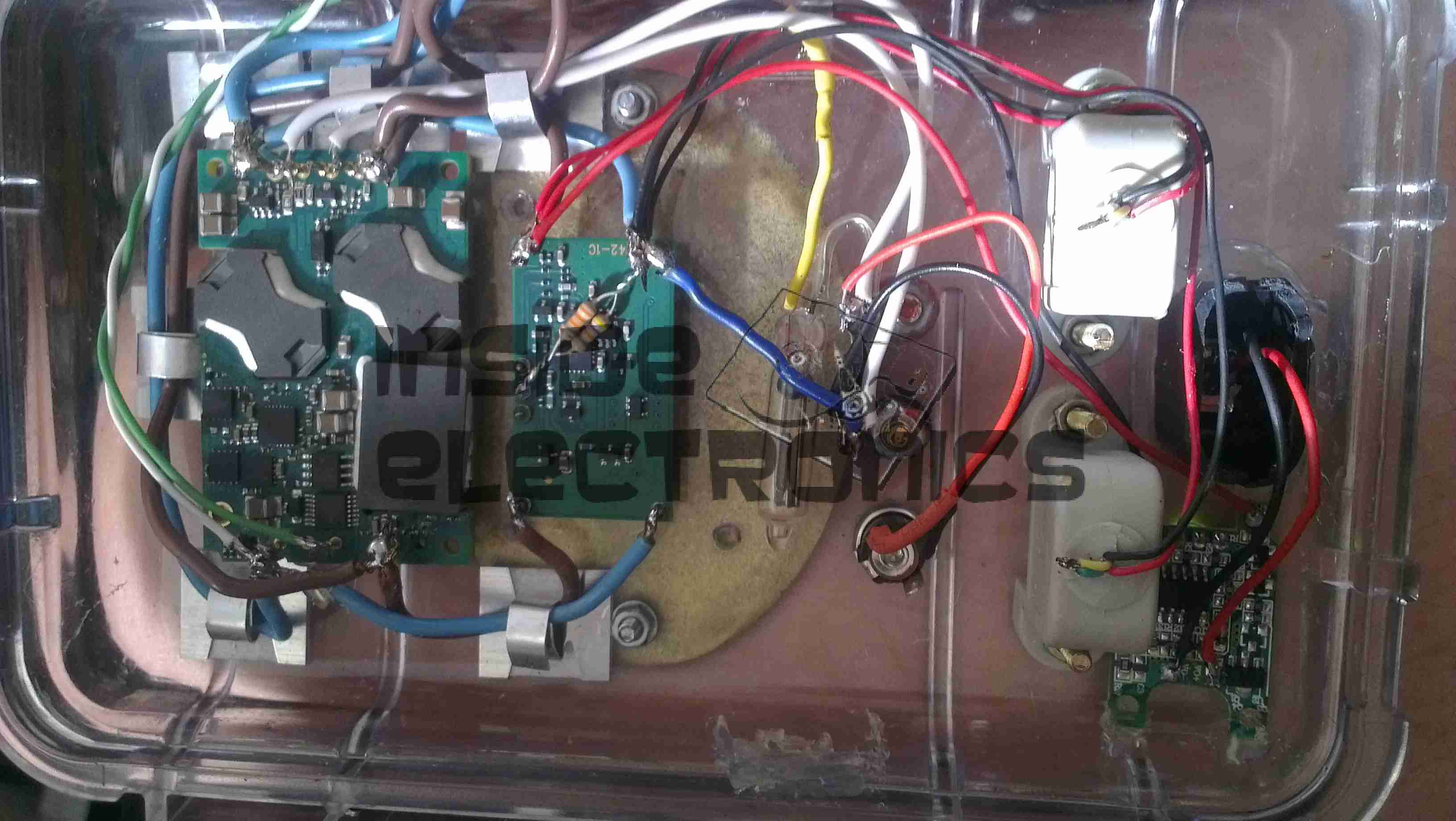
Main PCB
View of the main PCB is above, with the central Arduino Pro Mini module hosting the backend code. 12-24v power input, sensor input & 5v sensor power output is on the connectors on the left, while the pair of pump outputs is on the bottom right, switched by a pair of IRFZ44N logic-level MOSFETS. Onboard 5v power for the logic is provided by the LM7805 top right.
Code & PCB design is still under development, but I will most likely post the design files & Arduino sketch once some more polishing has been done.
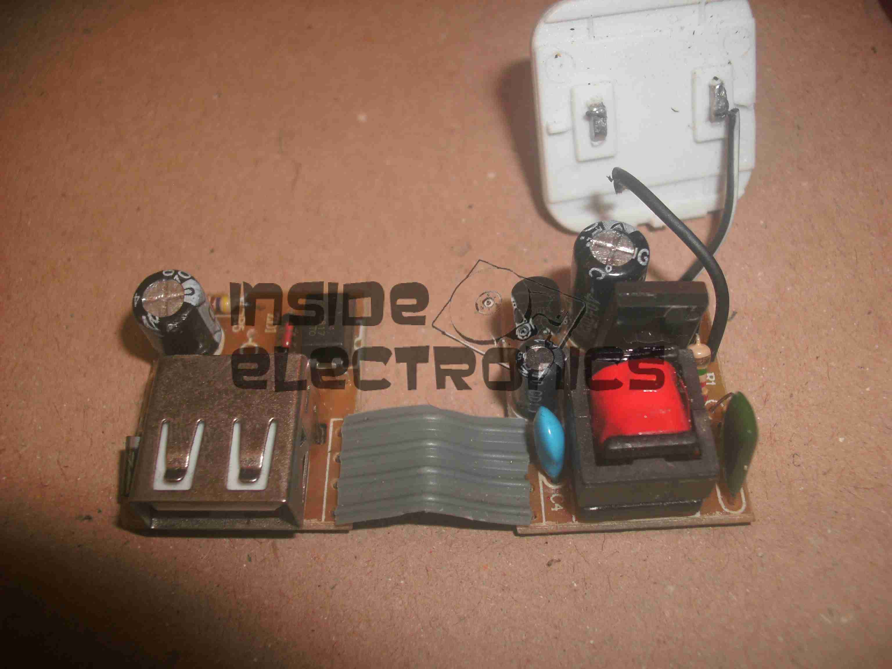
I received this USB supply with a laser module from China that I purchased on eBay. I have heard of these nasty copies of Apple chargers going around, but I’d never received one this bad with a piece of Chinese electronics.
Label
Model No. A1265, so definitely an Apple clone. Apparently capable of +5v DC 1A output. Notice the American NEMA pins. This wouldn’t have been any use to me in the first instance since I am resident in the UK & our mains plugs are significantly different, not to mention significantly safer.
Manufacturer is marked as Flextronics.
Top Of Boards
Here is the charger disassembled. Inside the case these two boards are folded together, creating an alarmingly small isolation gap between the mains side of the supply & the 5v output. Both the low voltage output & the feedback loop for the supply runs over the 4-core ribbon cable.
The mains wiring from the board is as thin as hair, insulation included, so there is a big possibility of shorts all over the place from this part of the circuit alone.
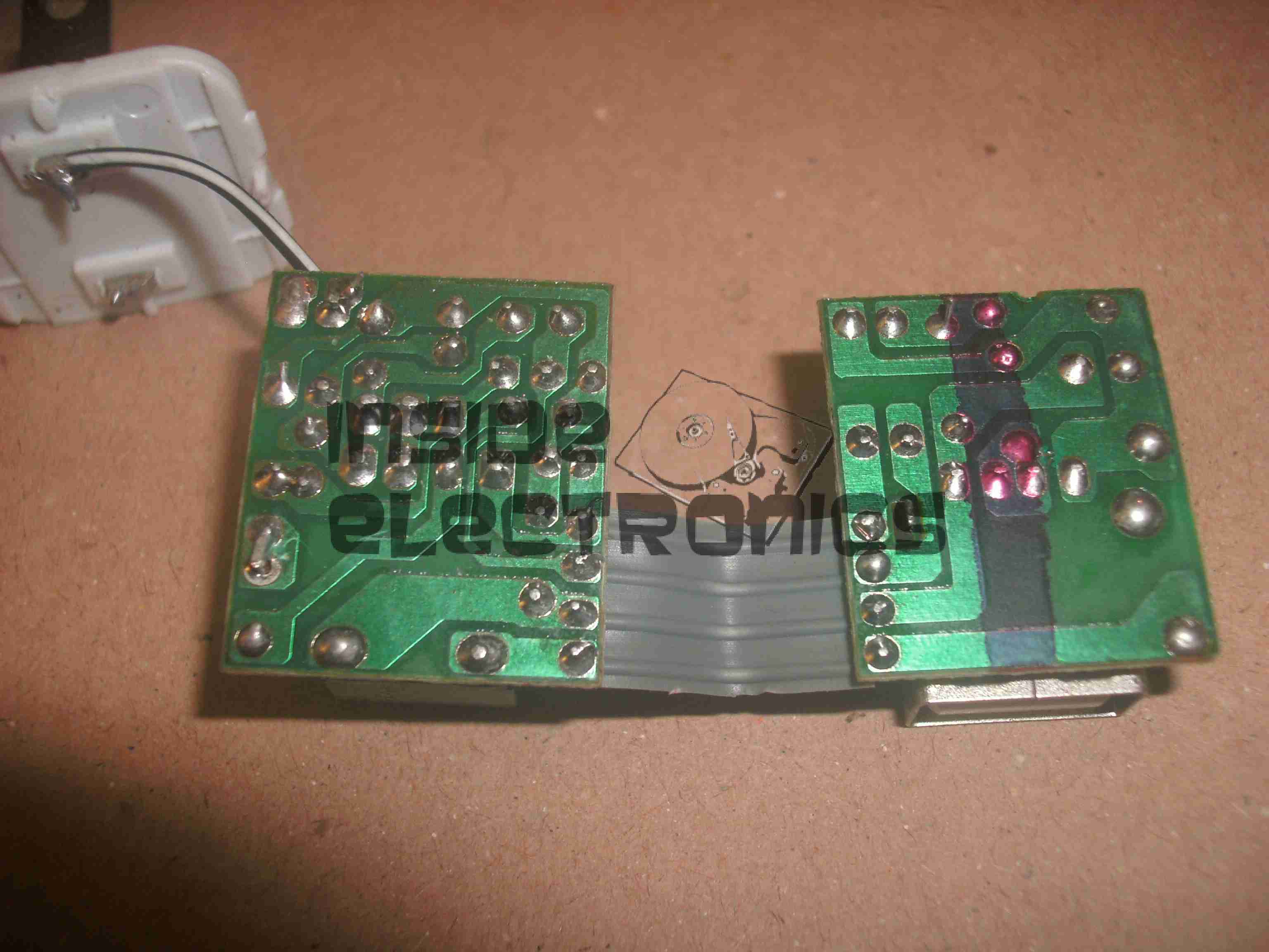
Bottom Of Boards
Bottom of the PCB assemblies. Good luck finding any creepage distance here. There simply isn’t any at all. traces on the +350v DC rail on the mains side of the transformer are no more than 1mm away from the supposedly isolated low voltage side.
Plugging one of these devices into anything is just asking for electrocution.
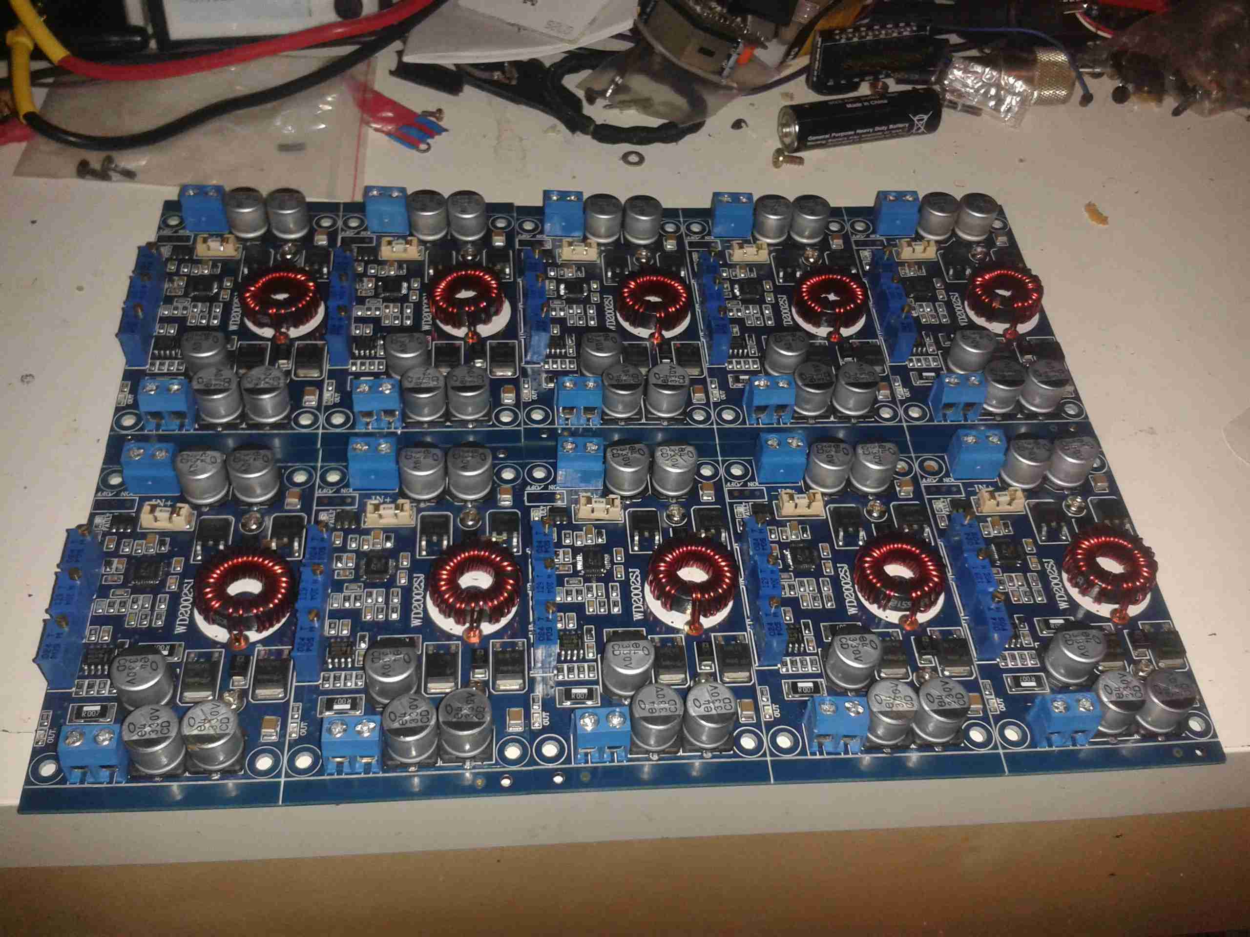
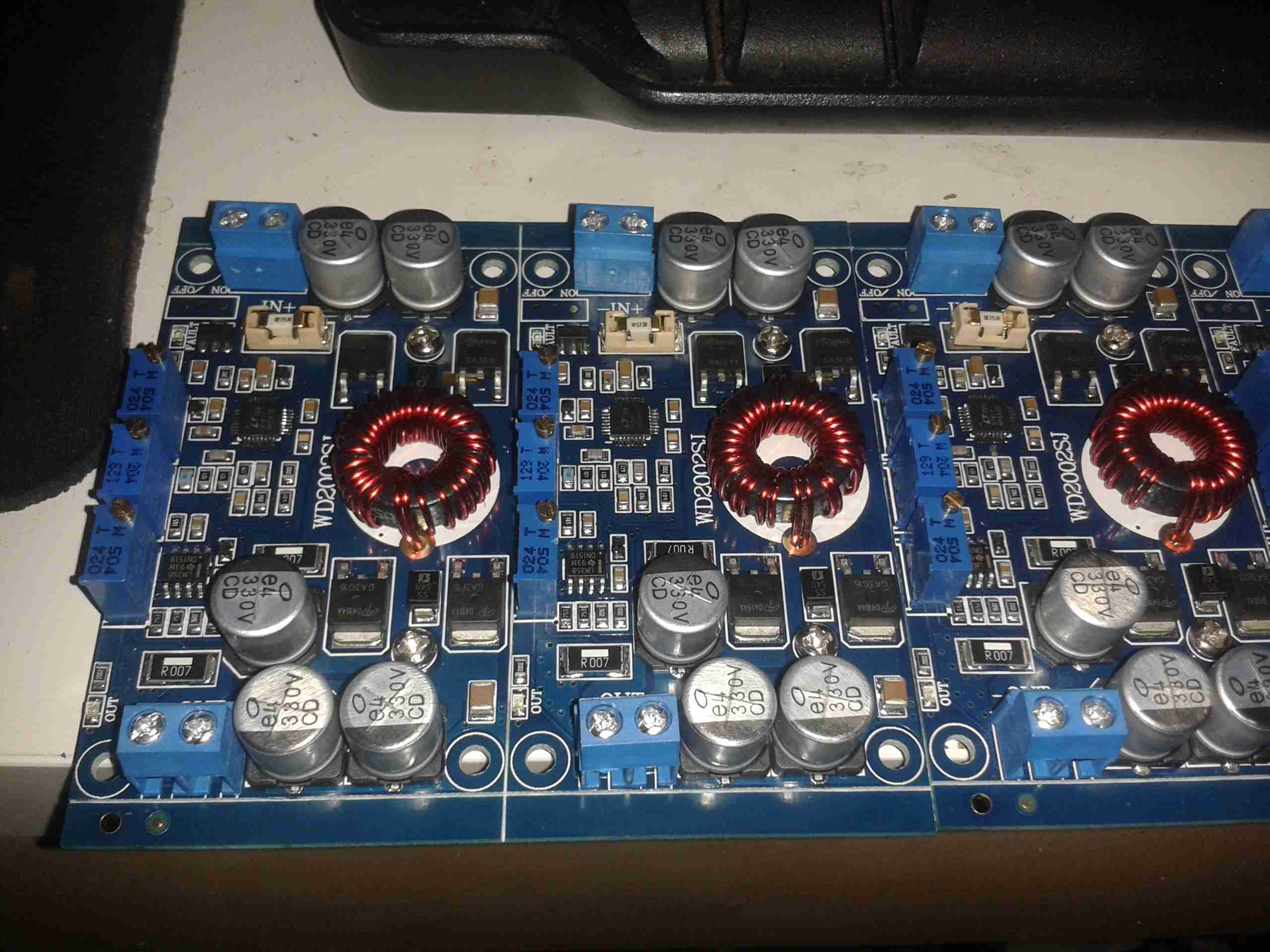
The original LM2577 based regulators I designed into my mobile battery pack turned out to be insufficient for requirements, therefore they have been replaced with higher capacity regulators.
The 12v regulator (left) is a muRata UQQ-12/8-Q12P-C SEPIC converter, providing a max of 8A at 12.1v DC. The 12v rail is also now independently switchable to save power when not in use.
The 5v regulator (right) is a Texas Instruments PTN78020WAZ switching regulator, rated at 6A. The pair of resistors on the back of the regulator set the output voltage to 5.1v.
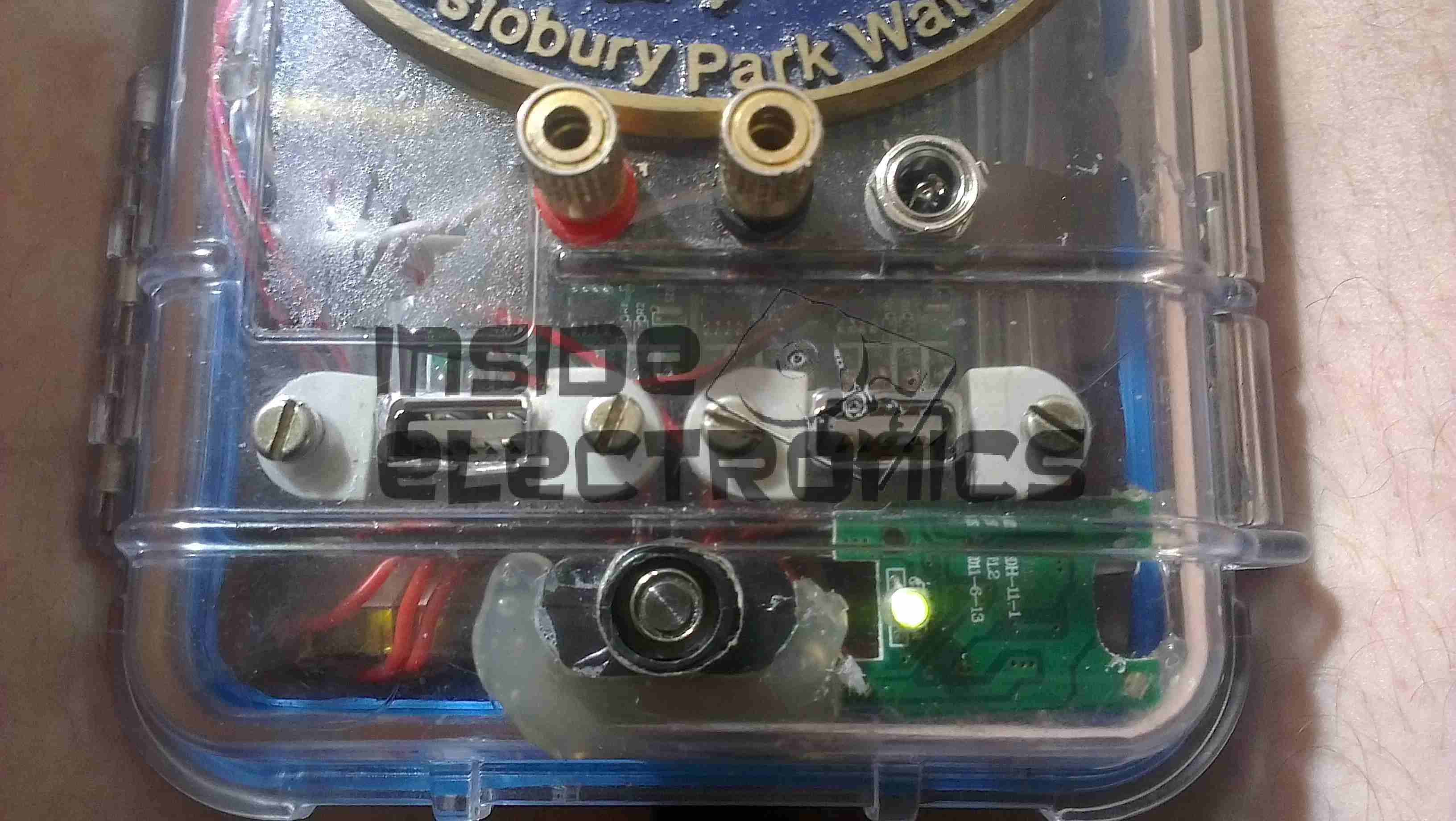
Also a new addition is a pair of banana sockets & a 2.1mm DC jack, wired into the 12v DC bus, for powering various accessories.
New Additions
Below the USB sockets is now a built in eCig charger, to save on USB ports while charging these devices.
IWA National Festival 2013
These changes were made after much field testing of the unit at Cassiobury Park, Watford, for the IWA National Waterways Festival.
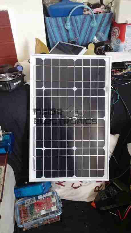
I have acquired a 24W monocrystalline solar panel to charge my portable battery pack while on the move. This panel will be able to charge all devices I carry on a regular basis with nothing but some sunlight!
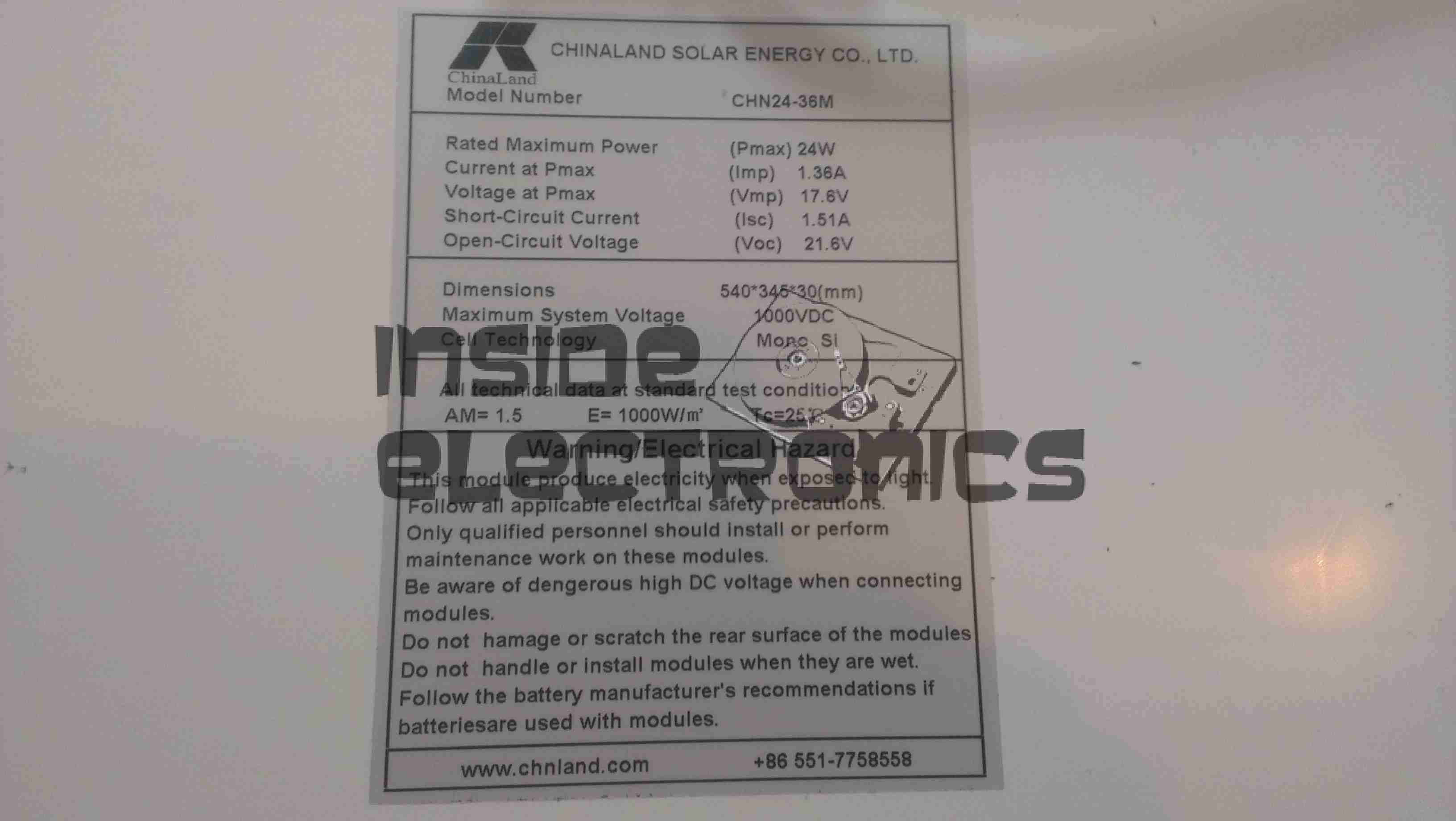
Info Panel
Info on the panel itself. Rated at 24W with nominal 17.6v DC, 1.36A output.
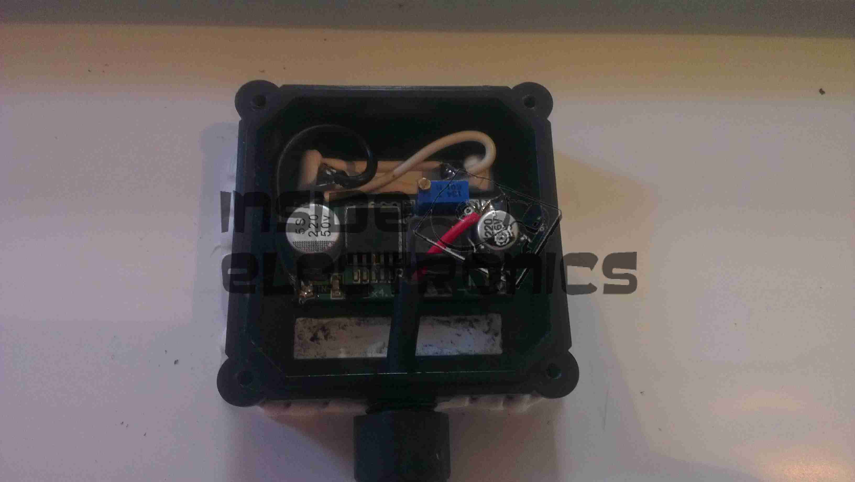
Regulator
I have installed a switching regulator in the back of the panel, where the connections would normally be wired straight to the array of cells. This regulates the voltage down to a constant 13.8v to provide more compatibility with 12v charging equipment. I have tested the output of the panel in late day sun, at 1.27A.
A few modifications were required to the SMPS modules to make the power rails stable enough to run the Pi & it’s monitor. Without these the rails were so noisy that instability was being caused.
I have replaced the 100µF output capacitors & replaced them with 35v 4700µF caps. This provides a much lower output ripple.
There are also heatsinks attached to the converter ICs to help spread the heat.
Here is the project I’m currently working on. A completely wearable computing platform based on the Raspberry Pi & the WiFi Pineapple.
Above can be seen the general overview of the current unit.
On the left:
Alfa AWUS036NHA USB High Power WiFi Network Interface
512MB Model B Raspberry Pi, 16GB SD card, running Raspbian & LXDE Desktop. Overclocked to 1GHz.
On the right:
WiFi Pineapple router board
USB 3G card.
The WiFi, Pineapple & 3G all have external antenna connections for a better signal & the whole unit locks onto the belt with a pair of clips.
The Raspberry Pi is using the composite video output to the 7″ LCD I am using, running at a resolution of 640×480. This gives a decent amount of desktop space while retaining readability of the display.
The case itself is a Pelican 1050 hard case, with it’s rubber lining removed. The belt clips are also a custom addition.
Connections
Here are the connections to the main unit, on the left is the main power connector, supplying +5v & +12v DC. The plug on the right is an 8-pin connection that carries two channels of video, mono audio & +12v power to the display.
Currently the only antenna fitted is the 3G.
Connectors
Closeup of the connections for power, audio & video. The toggle switch is redundant & will soon be replaced with a 3.5mm stereo jack for headphones, as an alternative to the mono audio built into the display.
Test Run
Current state of test. Here the unit is running, provided with an internet connection through the Pineapple’s 3G radio, funneled into the Pi via it’s ethernet connection.
Pi Goodness!
Running on a car reversing camera monitor at 640×480 resolution. This works fairly well for the size of the monitor & the text is still large enough to be readable.
Stay tuned for Part 2 where I will build the power supply unit.
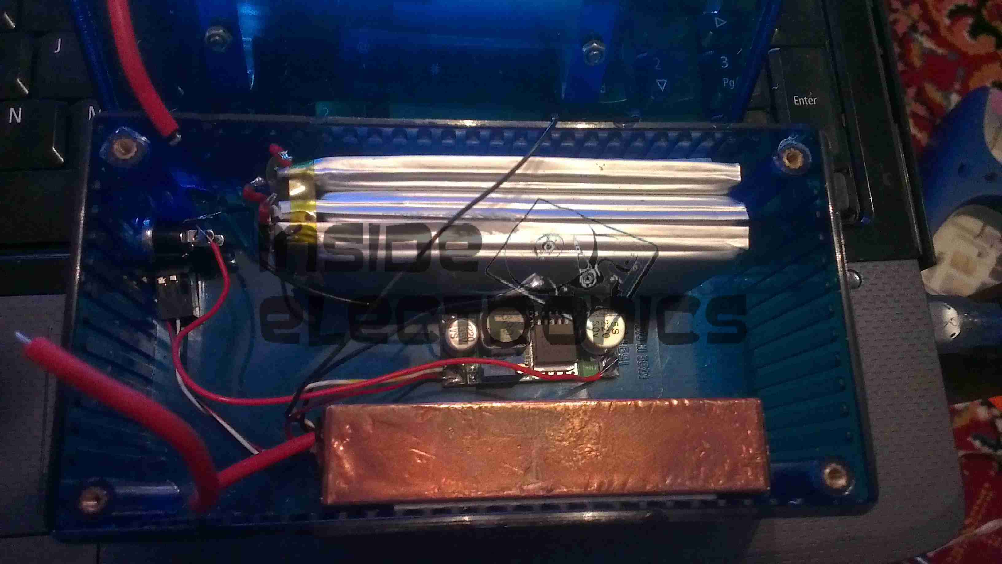
Having had a He-Ne laser tube for a while & the required power supply, it was time to mount the tube in a more sturdy manner. Above the tube is mounted with a pair of 32mm Terry Clips, with the power leads passing through the plastic top. The ballast resistor is built into the silicone rubber on the anode end of the tube. (Right).
Output power is about 1mW for this tube, which came from a supermarket barcode scanner from the 90’s. The tube is dated August 1993 & is manufactured by Aerotech.
Internals
Inside the box is the usual 2.2Ah 12v Li-Po battery pack & the brick type He-Ne laser supply. The small circuit in the centre is a switchmode converter that drops the 12v from the battery pack to the 5v required for the laser supply.
Here’s the regulator hooked up with test clips, on the right is the supply from the ultracapacitor bank, while on the left is the output, feeding a 2.3A brushless fan as a test load.
These regulators do get warm, even with no load, with a 2.3A load on the output, the temperature stays warm to the touch.
As an ultracapacitor has a pretty linear discharge curve, some electronics are required to make them behave more like batteries, such as as SEPIC converter.
On the right is a MuRata Power Solutions UQQ-12/8-Q12P-C switching regulator, which will accept a 9-36v input source & output a constant 12v at 8A (96W).
Just a quickie to note down the current progress of another project – Ultracapacitors.
Pictured right is a bank of 6 2.5v 2600F Maxwell Boostcaps, for a total of 15v at 433.333F. A total energy storage of 48.7kJ.
Coming soon will be the inclusion of charge balancing, using Zener diodes & integrating a DC-DC converter on the output to hold the bank voltage at 12v when being used.
Here I will document progress in replacing standard halogen MR10 lights with LEDs.
3x1W LED
These units are from TruOpto, available through Rapid Electronics in the UK. They are 3W total, from 3x 1W emitters on an aluminium back plate.
LED Test Rig
Here is the LED attached to a heatsink for testing purposes – these units dissipate nearly 2W in heat at full output.
As the lights are to be run from a 12v battery bank, for simplicity a master regulator is required to provide a stable 11.4v rail for LED supply.
Regulator Module
I have used a Texas Instruments part – PTN78020WAH. This is a 6A capable adjustable regulator module.
The LED lights are to be fully dimmable – the low voltage PWM dimmers are in progress of being built.
Tip Jar
If you’ve found my content useful, please consider leaving a donation by clicking the Tip Jar below!
All collected funds go towards new content & the costs of keeping the server online.