In my original review, I noted that this radio was supplied with a SO-259 socket for the antenna connection.
However I’m less than fond of these, due to their non-constant impedance, which can cause signal loss issues at VHF/UHF. Because of this, I’ve replaced it with a high quality N-type connector. These connectors are much better, as they are a constant 50Ω impedance, they’re weather resistant, and being rated to 11GHz, are more than sufficient for a radio that will only do up to 70cm.
RF Output Jack
Here can be seen the point where the connection is made to the PCB.
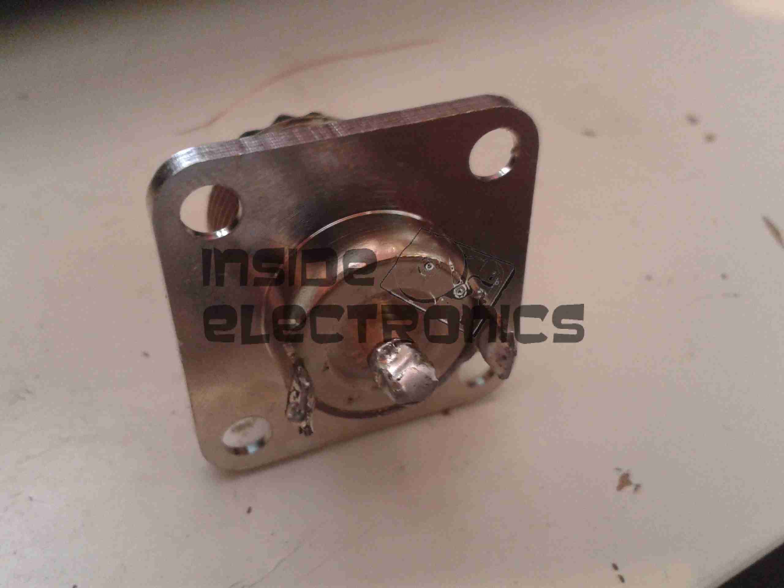
I’ve already replaced the socket in this photo. The pair of solder pads either side of the central RF point were soldered to wings on the back of the original SO-259. As there are a pair of screws, also connected to the ground plane, there have been no signal issues with just using the frame of the radio as the ground point. Shown below is the original socket, with the ground wings.
Original SO-259
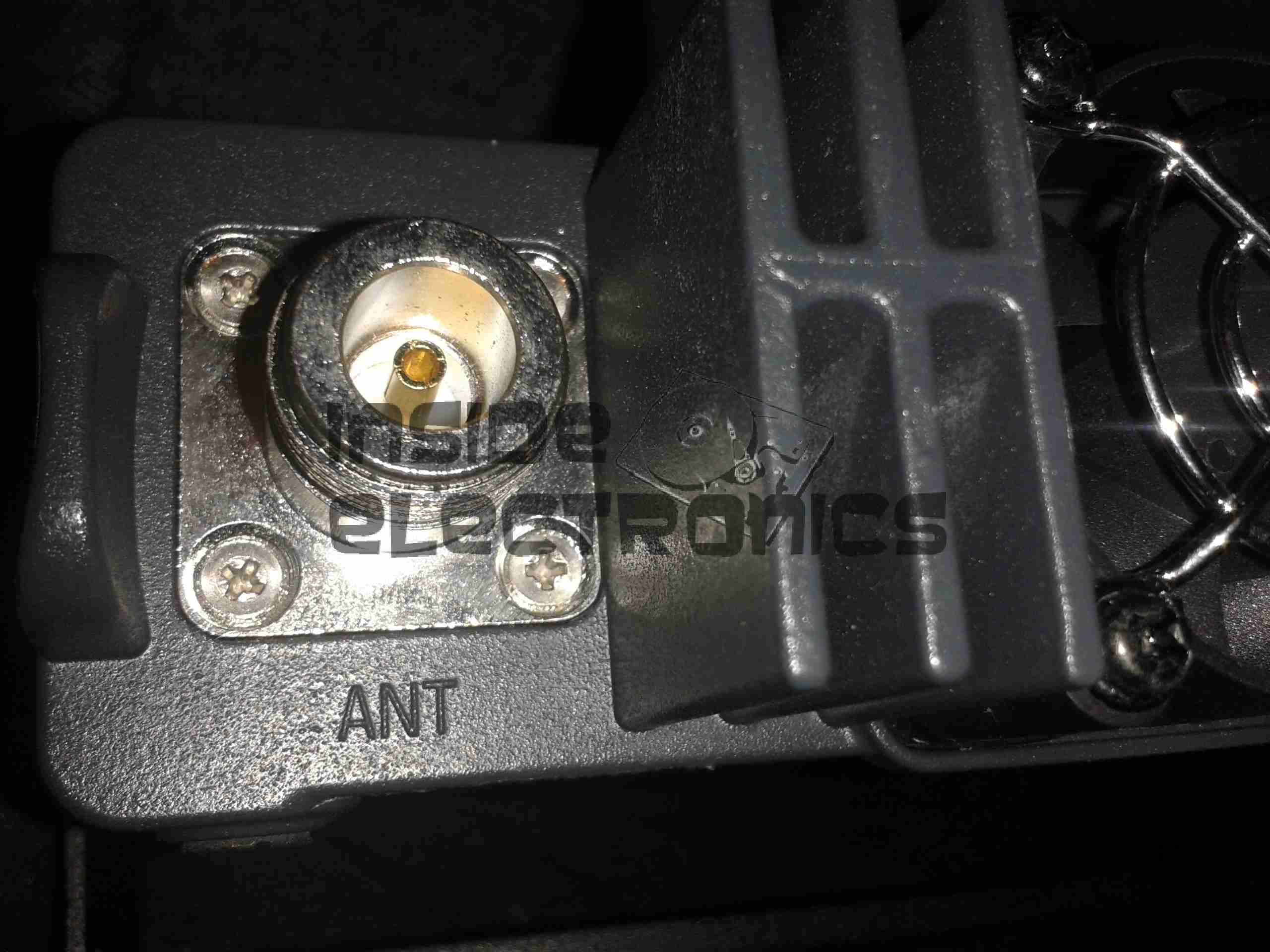
Finally, here is the back of the radio with it’s shiny new N connector.
New Connection
Chassis mount connectors are pretty standard, so this new connector fits perfectly into the same recess of the original. Looks like factory fitted!
I am now standardising on N connectors for everything in my radio shack, next on the project list for conversion is the SWR meter I recently acquired.
Here’s another viewfinder CRT, removed from a 1980’s vintage VHS camera I managed to get cheap from eBay.
This unit is very similar to the last one I posted about, although there are a few small differences in the control circuitry.
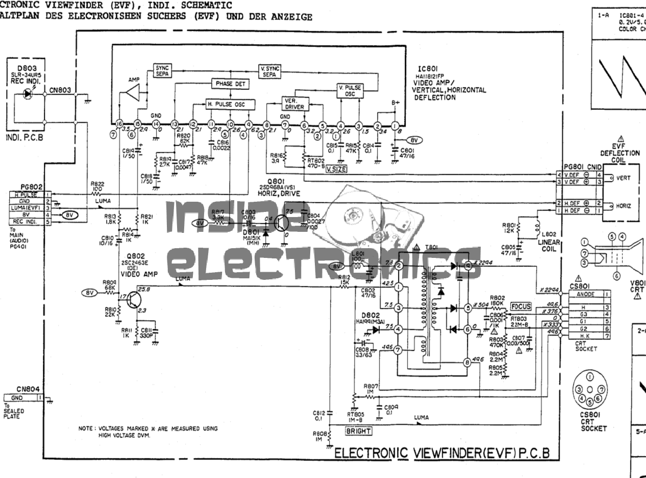
Viewfinder Schematic – Click to Embiggen
Here’s the schematic, showing all the functional blocks of the viewfinder circuitry. An integrated viewfinder IC is used, which generates all the required scan waveforms for the CRT.
On the left is the input connector, with the power & video signals. Only pins 2 (GND), 3 (Composite video), & 4 (+8v) are needed here. Pin 1 outputs a horizontal sync signal for use elsewhere in the camera, while pin 5 fed the recording indicator LED.
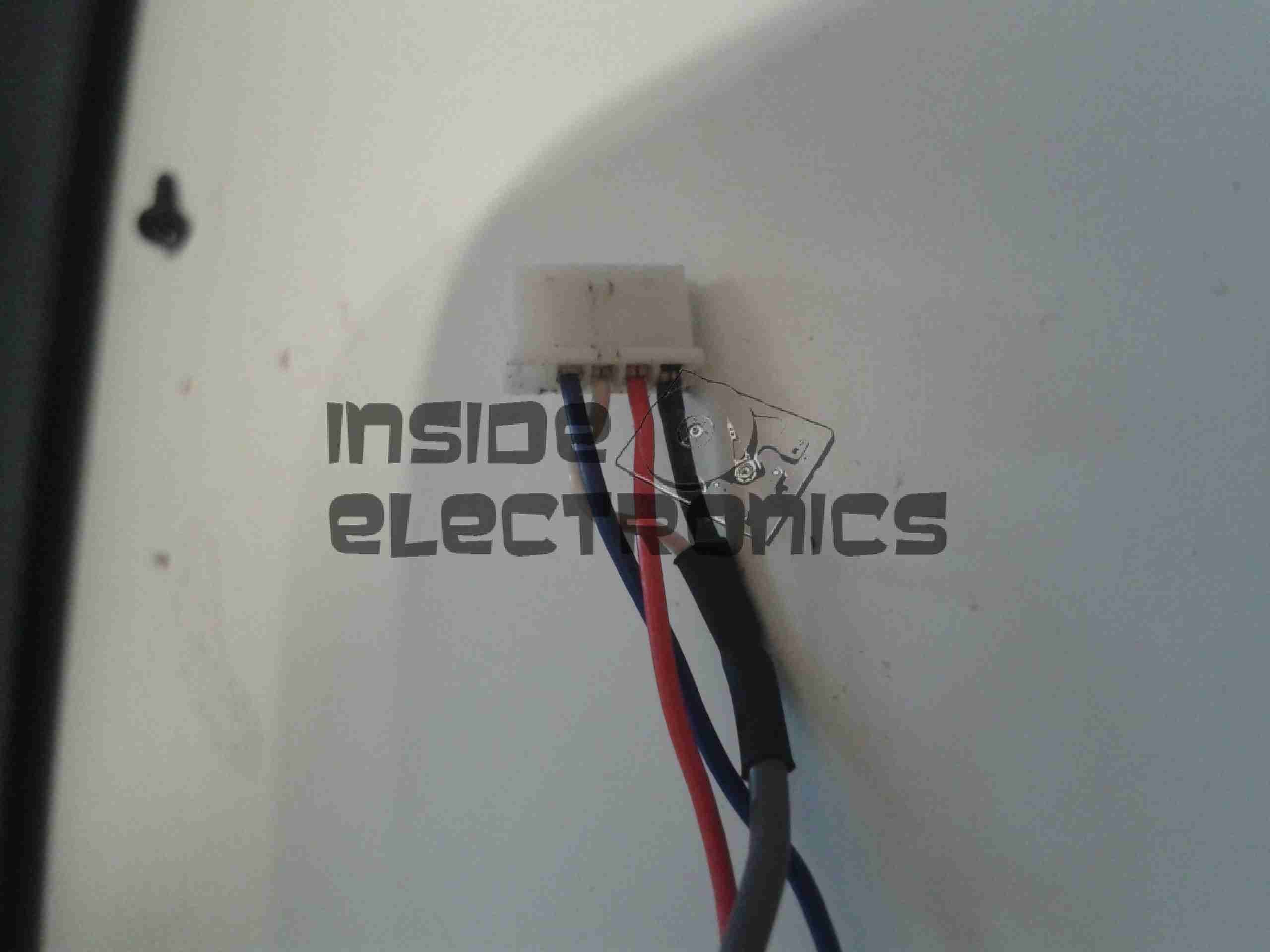
To make connection easier, I have rearranged the wires in the input connector to a more understandable colour scheme:
Input Connector
Red & Blue for power input, & a coax for the video. For the video GND connection, I have repurposed the Rec. LED input pin, putting a shorting link across where the LED would go to create a link to signal ground. Keeping this separate from the power GND connection reduces noise on the CRT.
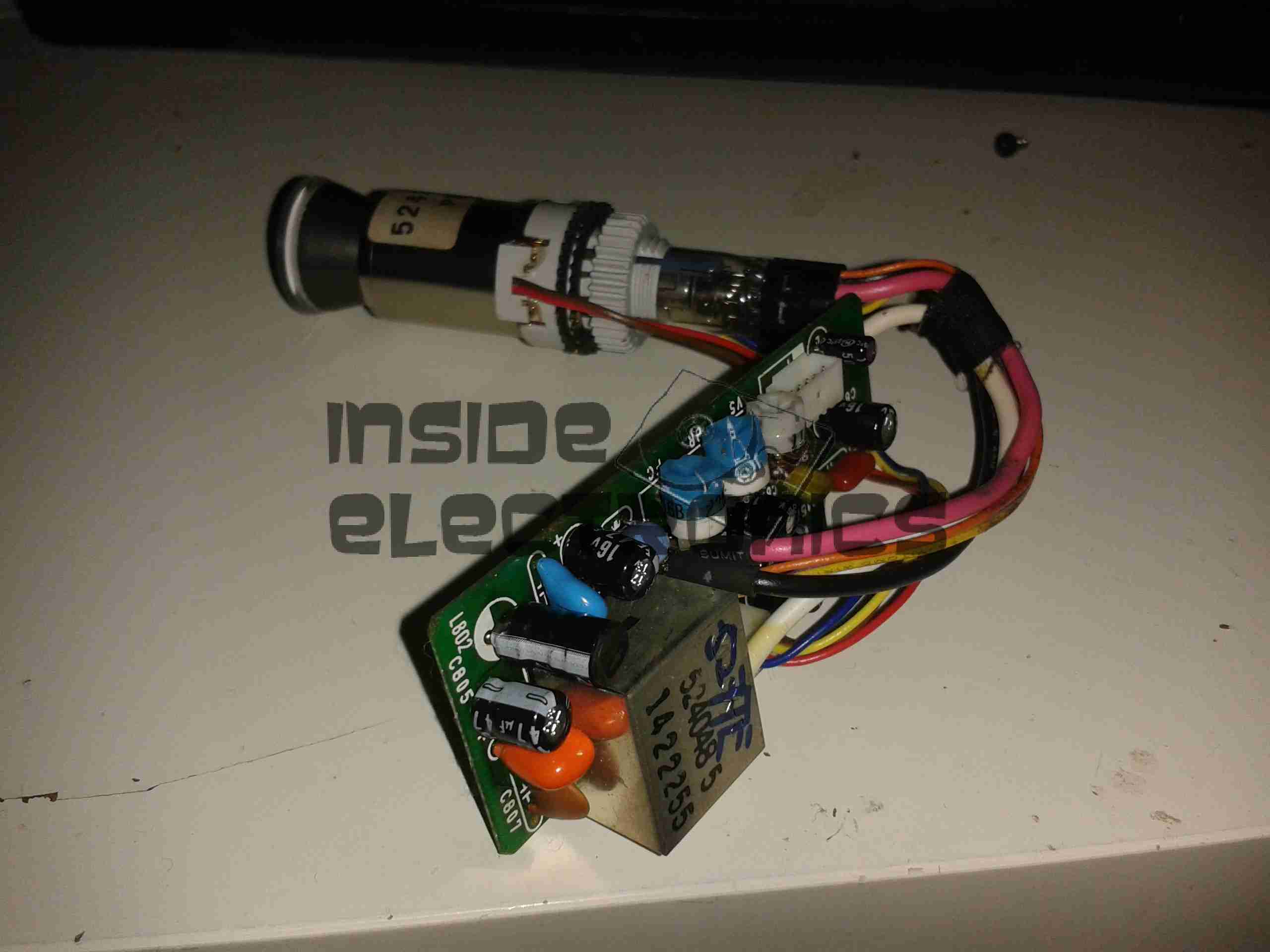
Viewfinder CRT Assembly
Here’s the complete assembly liberated from it’s plastic enclosure.
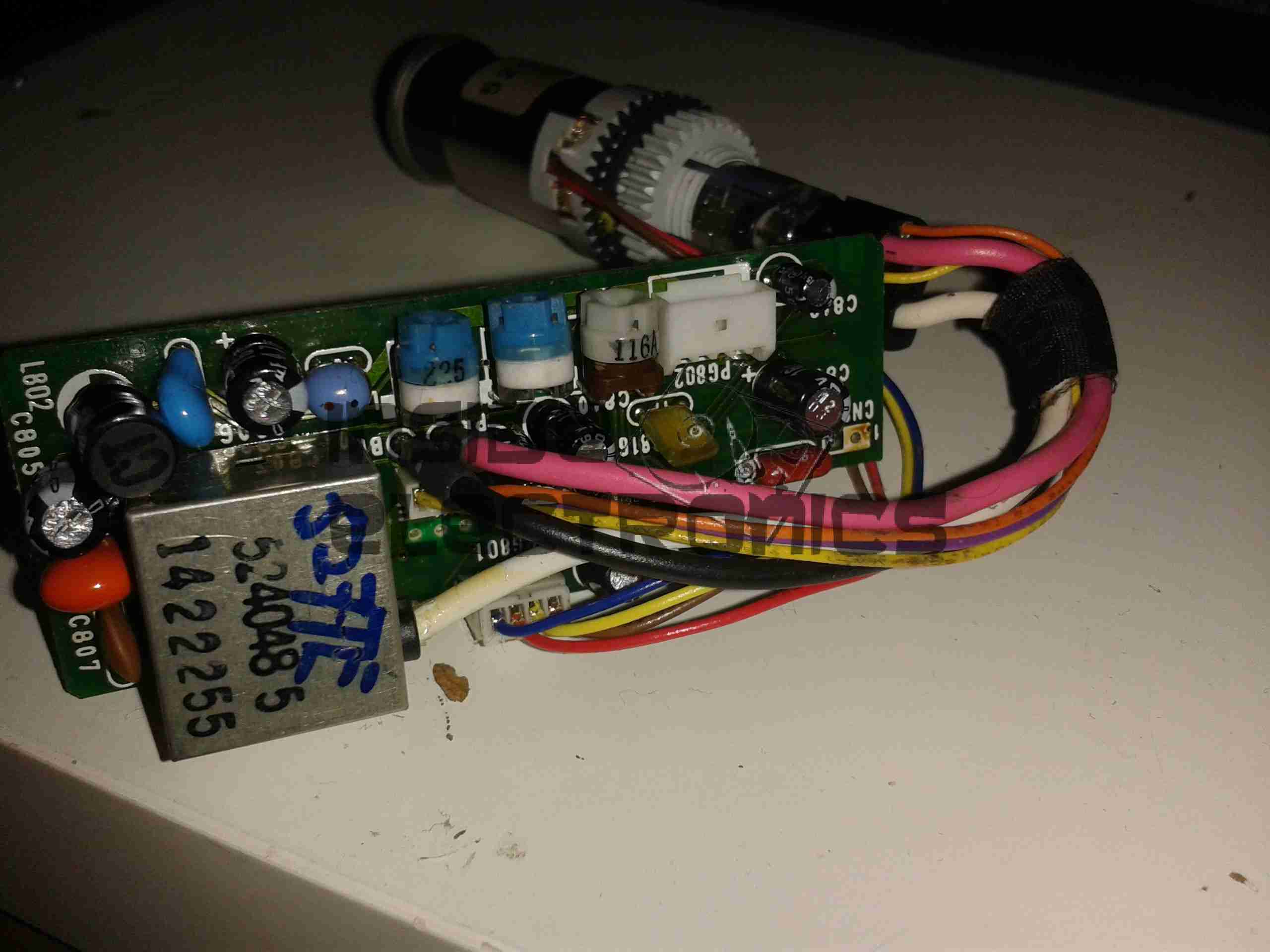
PCB Closeup
Closeup of the control PCB. The 3 potentiometers control the CRT brightness, focus & vertical size.
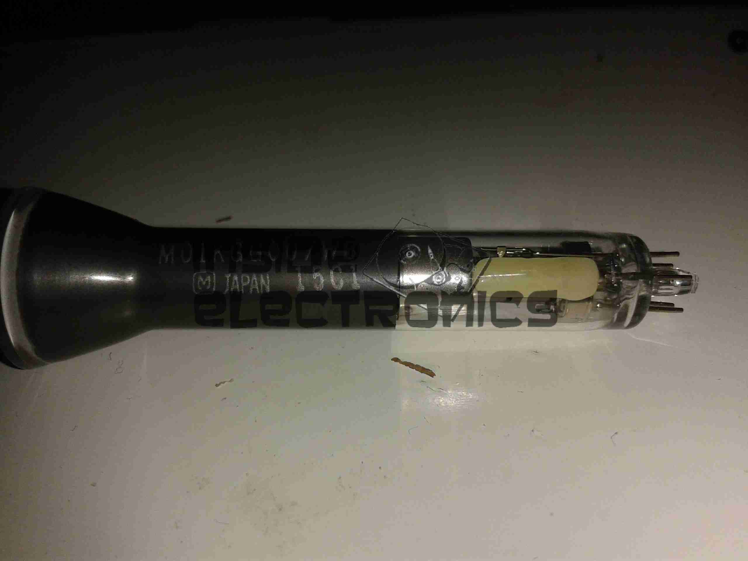
M01KGG007WB CRT
The tiny CRT. Only ~60mm in length, with an 18mm screen size. This tube runs on +2294v final anode voltage. Much higher than I expected.
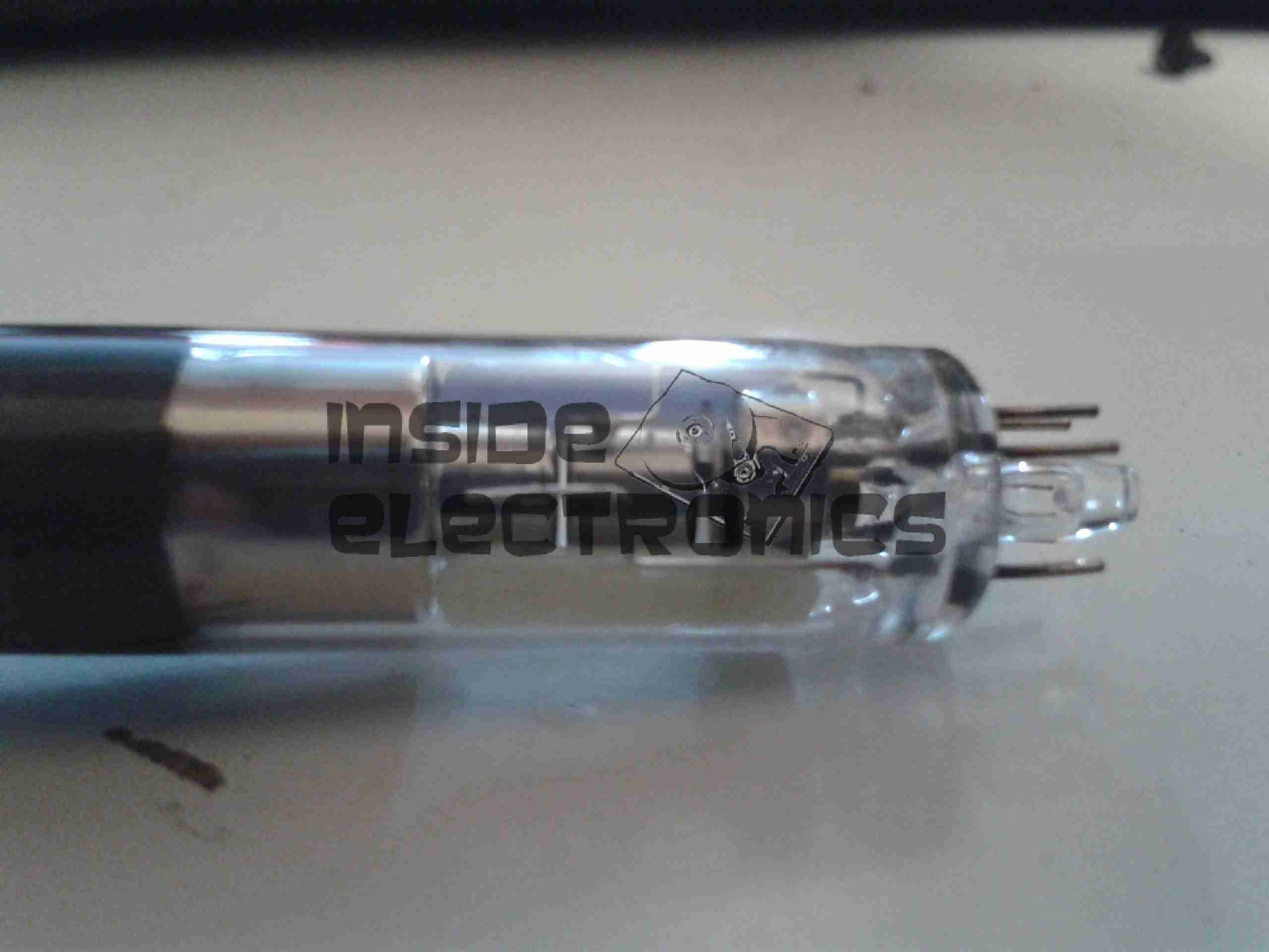
Electron Gun Closeup
The electron gun assembly, with the cathode, focus & final anode cups.
Phosphor Screen
This screen is just a little bigger than a UK 5p piece! A marvel of precision engineering.
Here’s another active balancing circuit for large ultracapacitor banks, this one is designed for a series string of 6, at 2.5v per capacitor.
Based on the design here, I have transcribed the circuit into Eagle & designed a PCB layout.
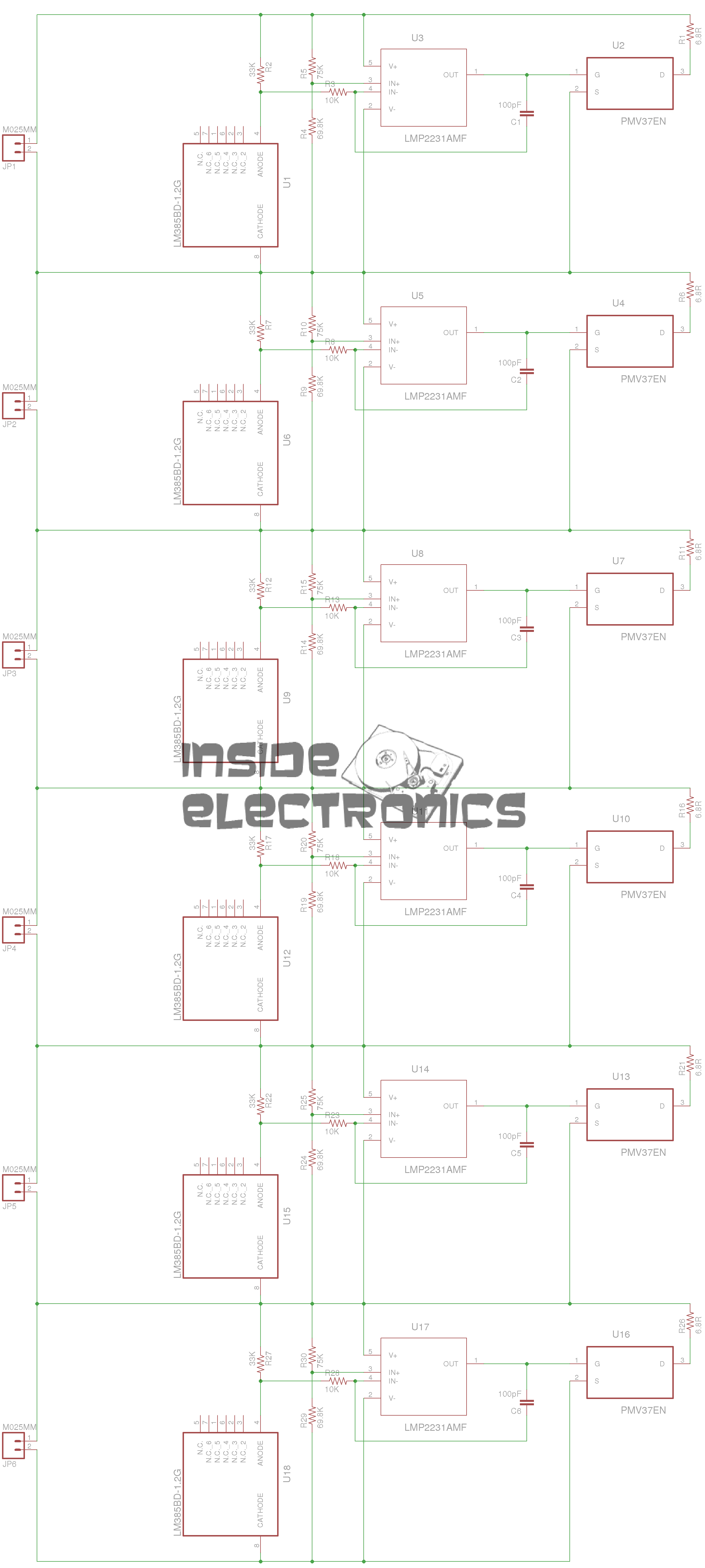
Ultracap Balancer Circuit – Click to Embiggen
As can be seen from the circuit diagram above, this is just 6 copies of the circuit from the above link, with screw terminals to attach to the capacitor string.
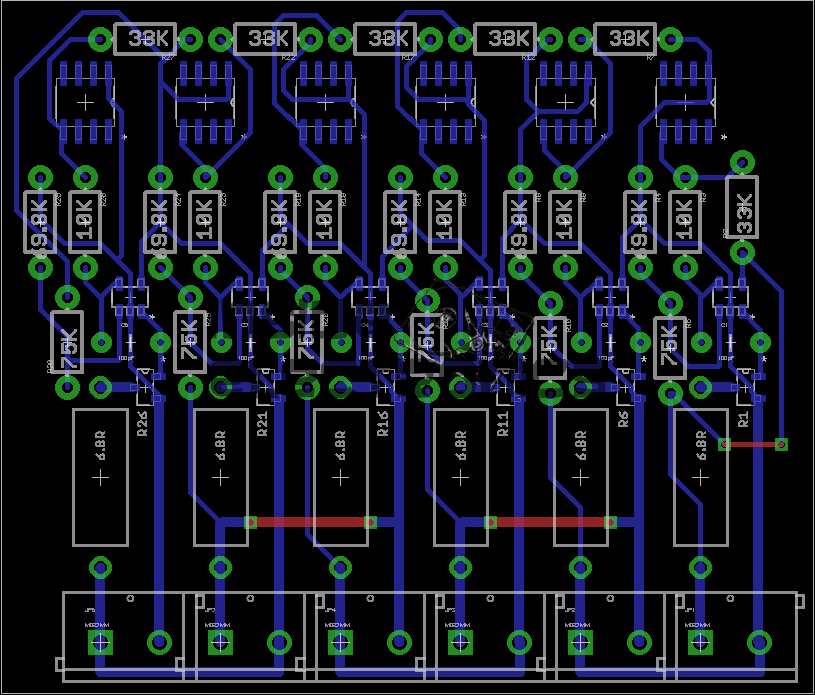
Ultracap Balancer PCB
And here’s the PCB. the MOSFETs & OpAmps are very small SMT parts, so require a steady hand in soldering. This board can easily be etched by hand as there’s only 3 links on the top side. No need for a double sided PCB.
As always, the Eagle project files & my Eagle library collection are available below:
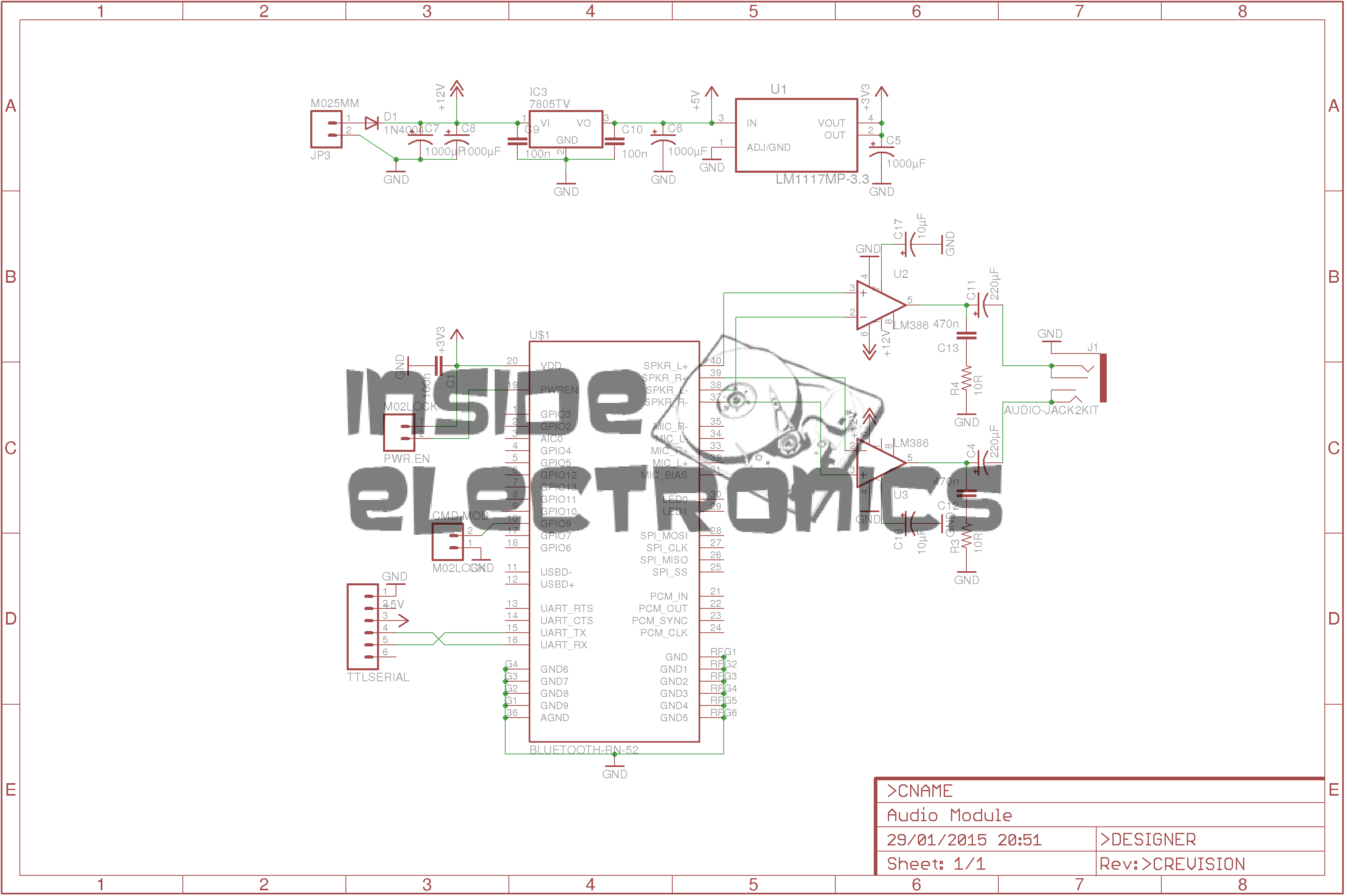
I’ve been doing some tinkering with the RN-52 Bluetooth Audio module from Roving Networks, in prep for building a portable wireless speaker system, & thought I’d share my designs.
Initially I was having some issues with RF noise on the audio output from the RN-52, as I was only using the outputs single-ended. The module didn’t like this treatment, with all the RF whine coming straight out of the speakers.
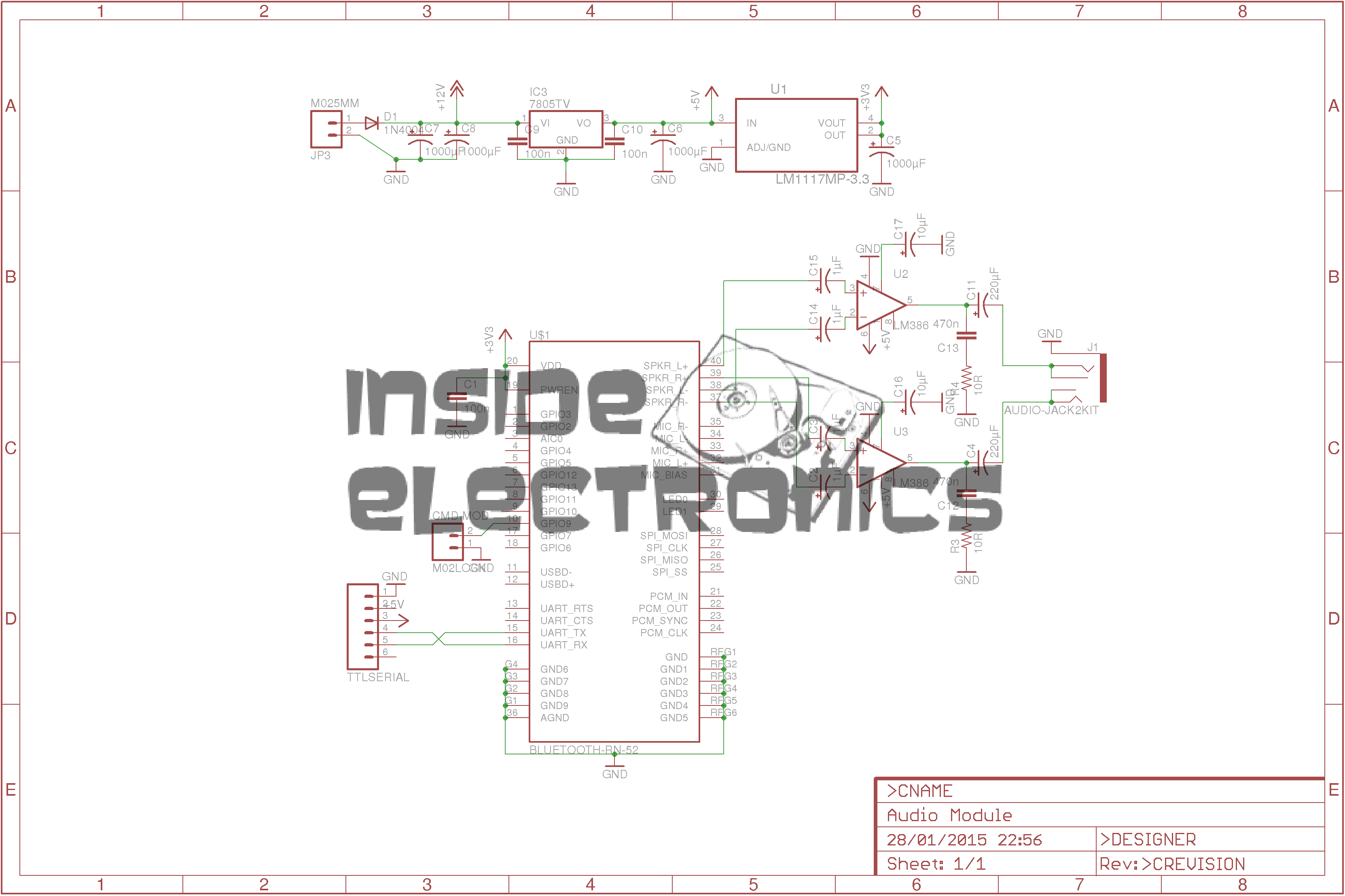
To fix this issue I have used a pair of jellybean LM386 audio power amplifiers, running in differential input mode. This solves the high-pitched whine when the audio is enabled, & also allows the module to directly drive a set of 32Ω headphones at a reasonable level.
In Eagle I have designed a simple board, routing only the audio output, serial TTL & command mode pins out, along with the supporting power supply circuitry to operate from 12v DC.
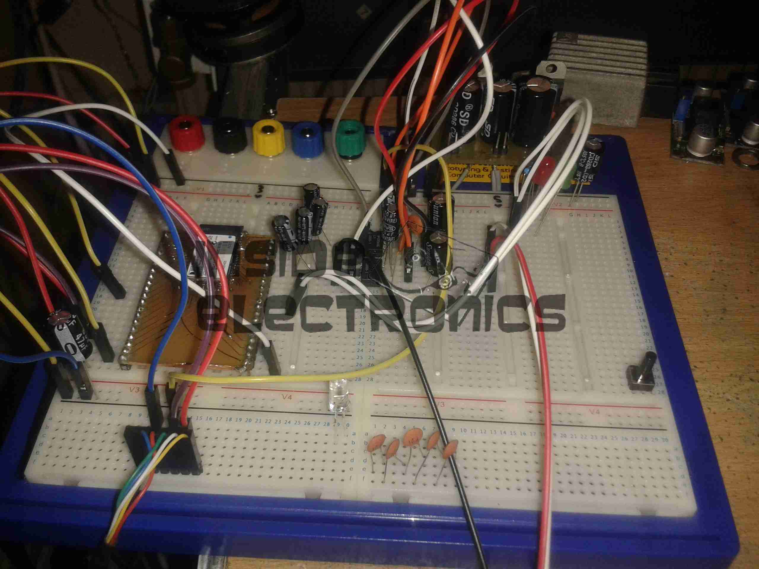
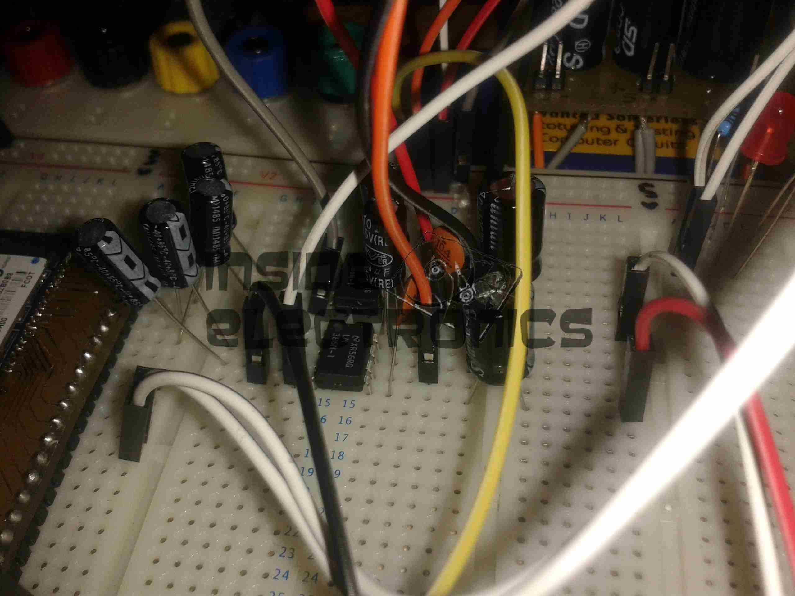
RN-52 Breadboard
Above is the current incarnation of the circuit on the breadboard. The RN-52 is on the left, audio power stage in the centre & headphone output on the right.
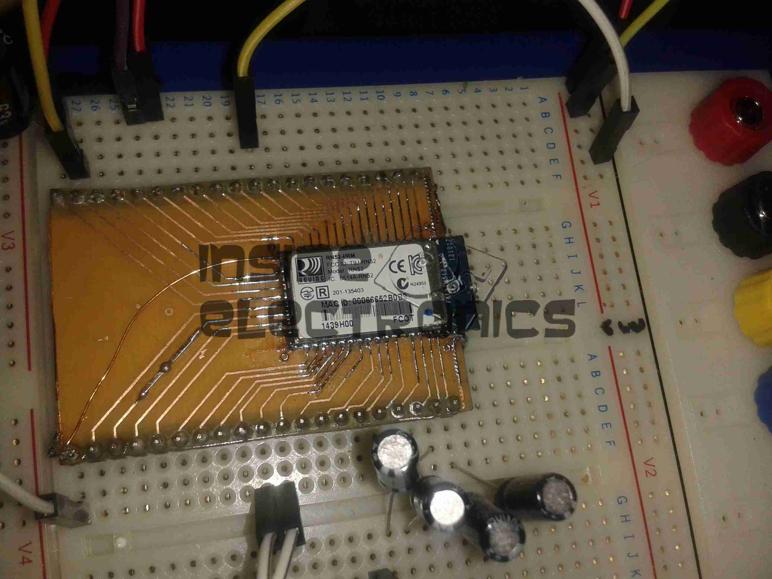
RN-52 Breakout
The bluetooth module on a breakout board. I was cheap in this case & etched my own board. I’m not paying Sparkfun, (as much as I like them), an extra ~£10 for a small PCB with the pins broken out. Much cheaper to spend 15 minutes with the laser printer & the iron, & do a toner transfer PCB.
As this board is single sided, I added a ground plane on the underside with copper foil, to help with the RF issues. Breadboards really aren’t all that good at rejecting noise induced when there’s a 2.4GHz transceiver mounted on them.
LM386 Amplifier
The LM386 audio power stage. The differential inputs from the module are capacitively coupled with 1µF electrolytics. This setup remarkably reduced the noise on the output. I left these at their default gain of 20, as I’ll be connecting another high power amplifier stage to drive large speakers.
RN-52 Eagle Layout
Here’s the circuit laid out in Eagle, ready for PCB.
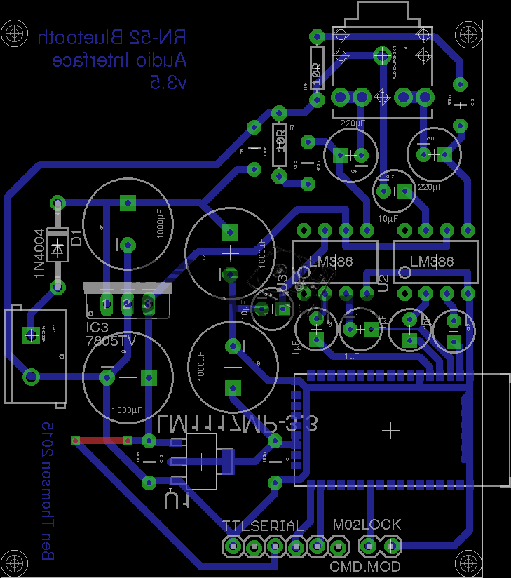
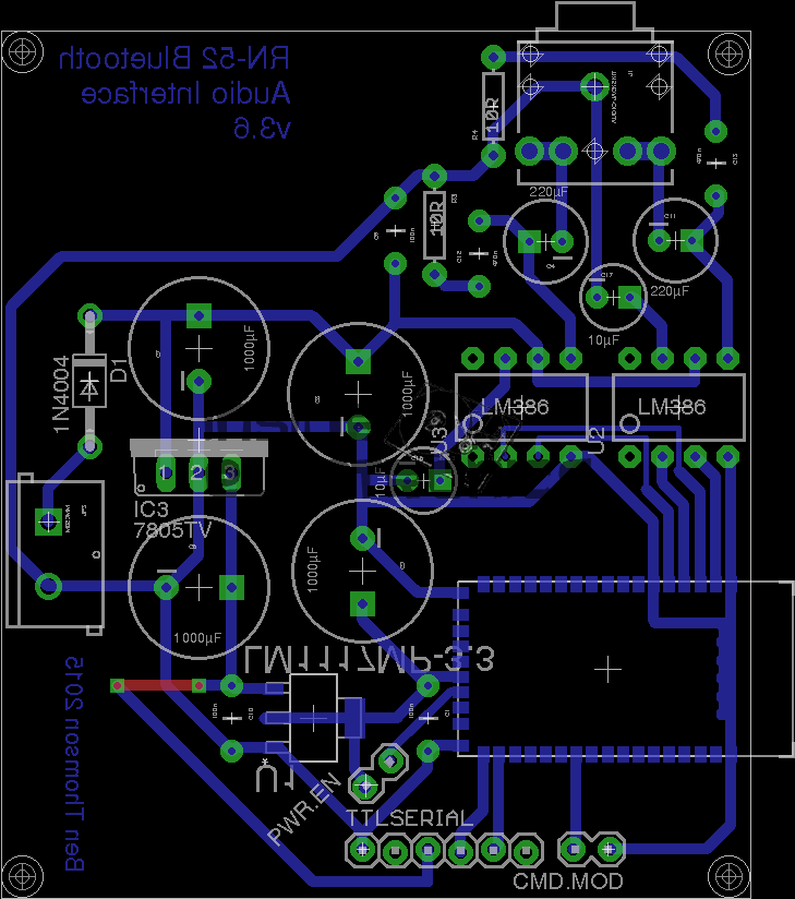
RN-52 Eagle PCB
And here’s the PCB layout. Only one link required for the +5v line from the TTL serial port.
As always, the Eagle PCB & Schematic layout files are available at the bottom of the article.
*Update 29-01-15*
Rerouted a few things:
Moved the audio power stage to the +12v rail to improve sound response. – As the LM386 has a max input voltage of 12v (absolute maximum 15v), a regulated supply is recommended. The LM386-N4 variant has a higher voltage range, up to 18v. This should be suitable for an unregulated supply.
Removed 1µF coupling capacitors to reduce distortion & amplifier hiss. The capacitors appeared to cause some instability on the amplifier, causing random distortion. Removing them has cured this. No signal hiss has also been reduced to a very low level.
Reversed input polarity on input of one of the amplifiers – this appears to produce better audio.
Added PWR.EN header to allow connection of power button. Saves hassle of cycling power to the board when the RN-52 goes into sleep mode.
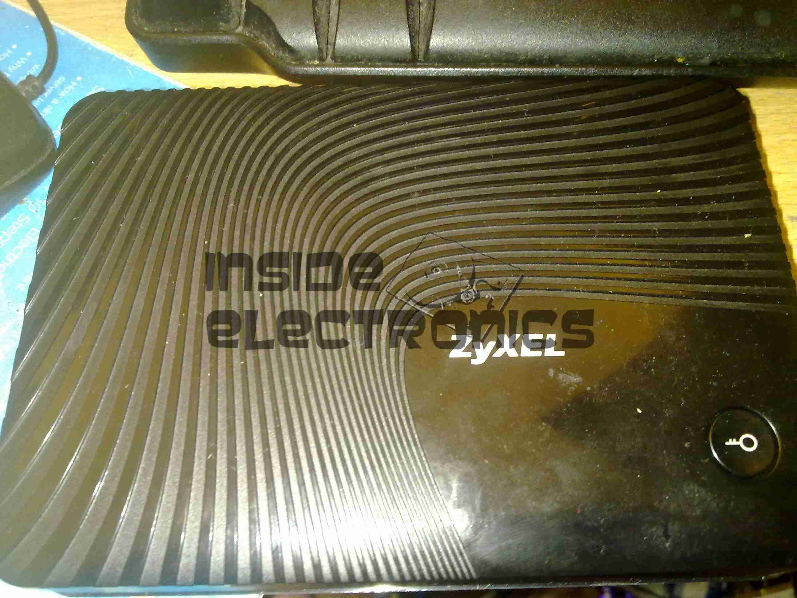
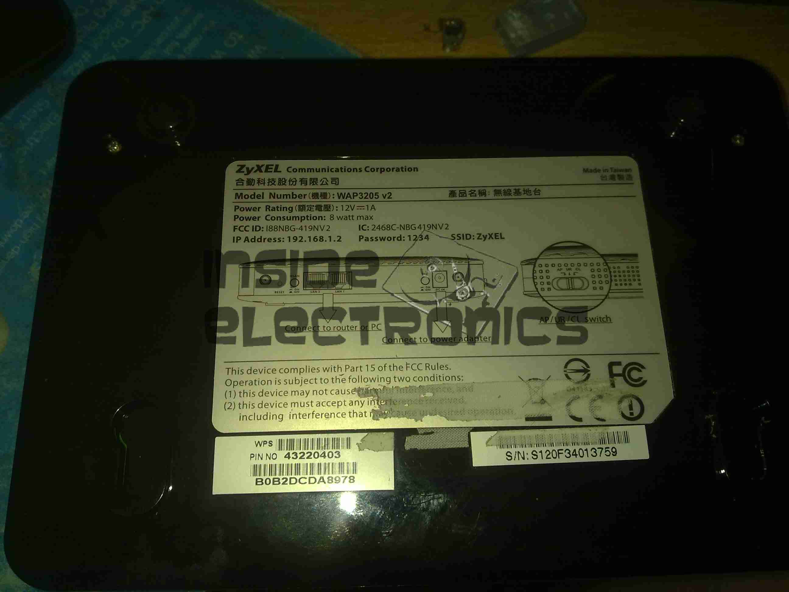
Here is a ZyXel WAP3205 WiFi Access Point that has suffered a reverse polarity event, due to an incorrect power supply being used with the unit.
ZyXEL WAP3205
While most electronic gadgets are protected against reverse polarity with a blocking diode, this unit certainly wasn’t. Applying +12v DC the wrong way round resulted in this:
Blown Switchmode IC (Fuzzy Focus)
That is the remains of the 3.3v regulator IC, blown to smithereens & it even attempted an arson attack. Luckily this was the only damaged component, & I was able to repair the unit by replacing the switching IC with a standalone regulator. (Replacing the IC would have been preferable, if there was anything left of it to obtain a part number from).
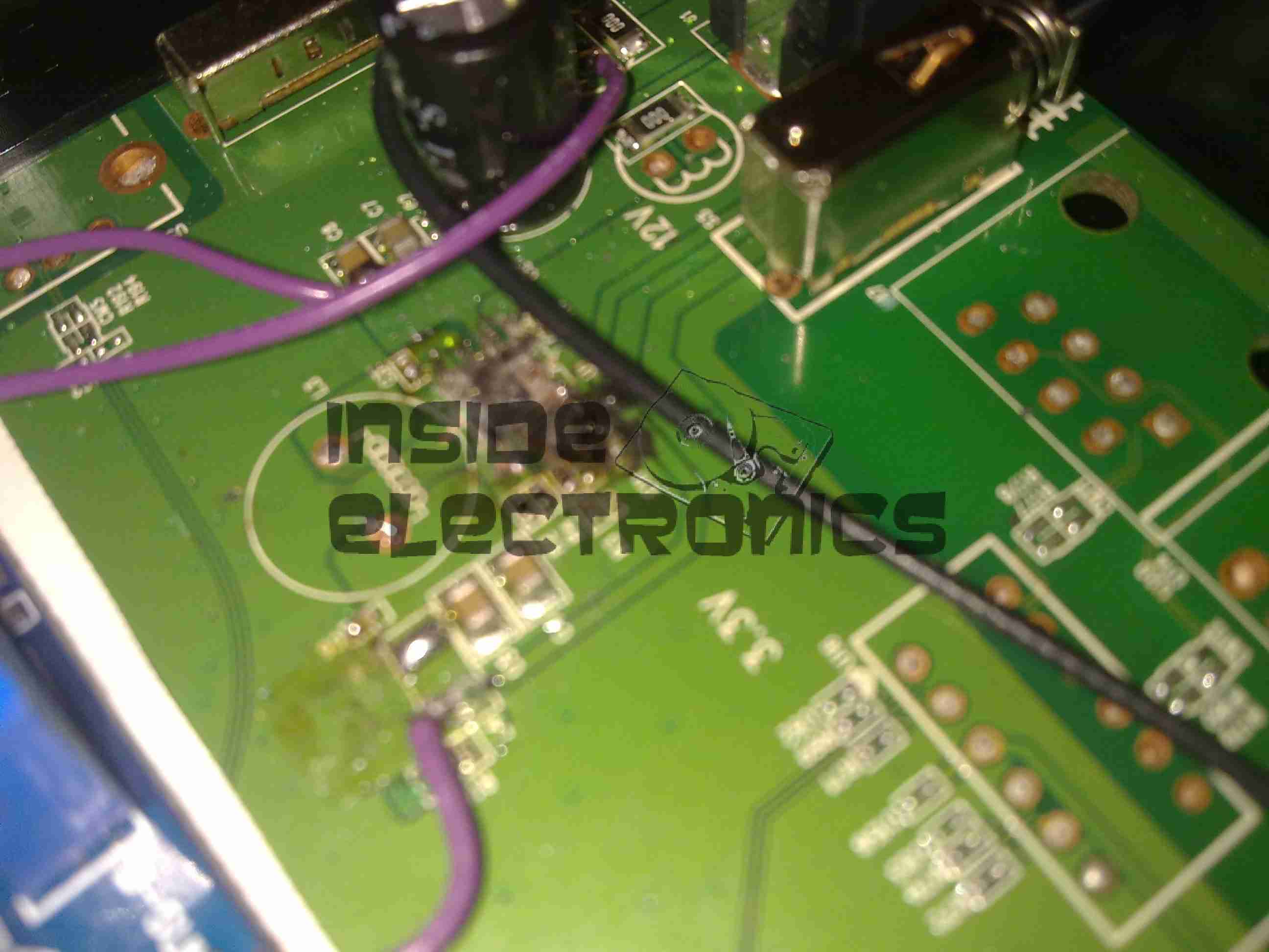
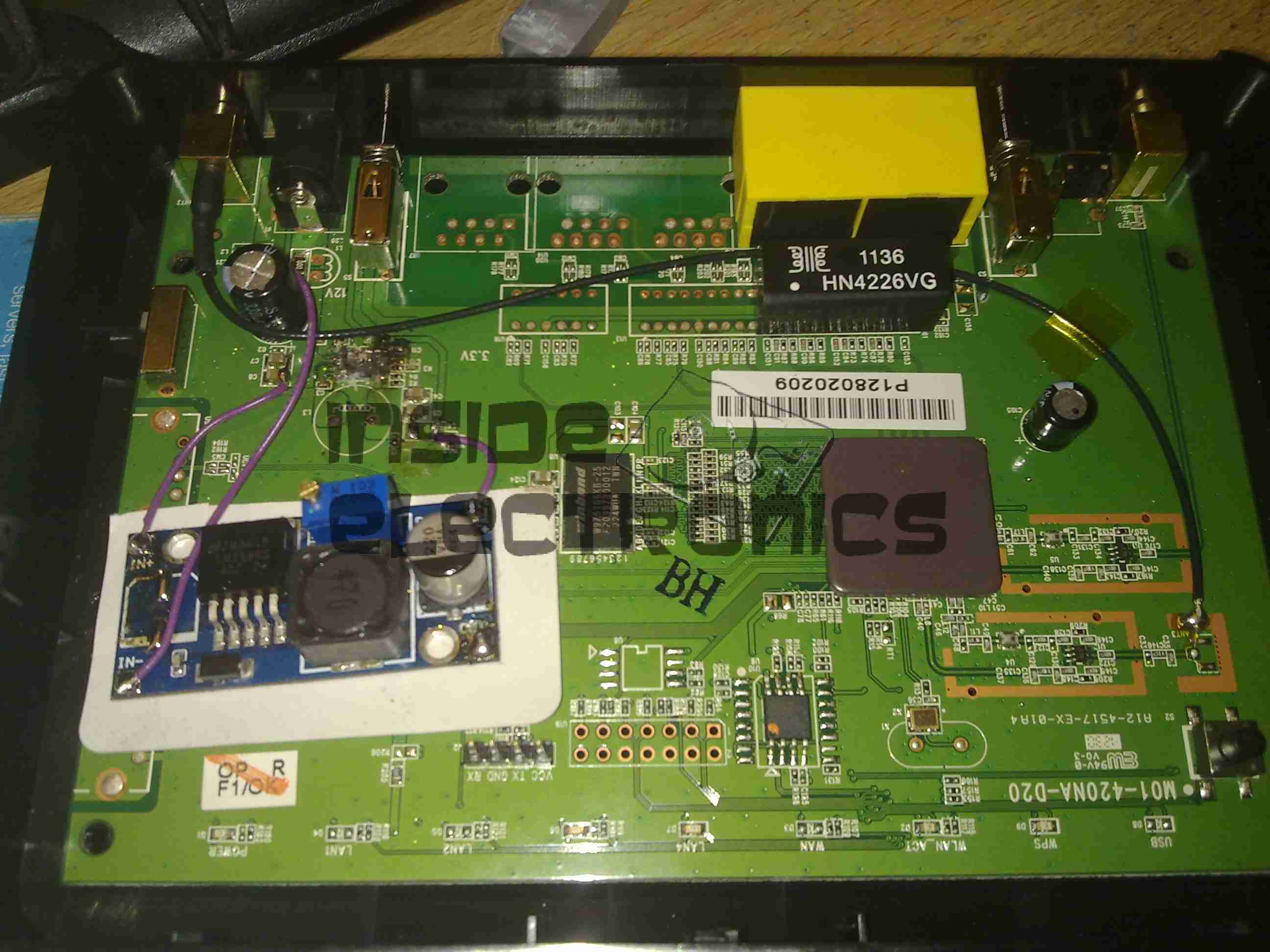
I scraped away the pins of the IC to clear the short on the input supply, removed the switching inductor, & tacked on an adjustable regulator module set to 3.3v. Luckily the voltage of the supply is handily marked on the PCB next to the circuit.
Replacement PSU
Replacement SMPS in place on top of the PCB. The output of the supply is connected to one of the pads of L4 (on my unit just an 0 ohm link), the +12v input is connected to the + rail side of C8 & C7 & the final ground connection is hooked in to the back of the barrel jack.
After this replacement, the unit booted straight up as if nothing had happened. All the logic is undamaged!
Continuing from my previous post where I published an Eagle design layout for AD7C‘s Arduino powered VFO, here is a completed board.
I have made some alterations to the design since posting, which are reflected in the artwork download in that post, mainly due to Eagle having a slight psychotic episode making me ground one of the display control signals!
AD9850 VFO
The amplifier section is unpopulated & bypassed as I was getting some bad distortion effects from that section, some more work is needed there.
The Arduino Pro Mini is situated under the display, and the 5v rail is provided by the LM7805 on the lower left corner.
Current draw at 12v input is 150mA, for a power of 1.8W total. About 1W of this is dissipated in the LM7805 regulator, so I have also done a layout with an LM2574 Switching Regulator.
The SMPS version should draw a lot let power, as less is being dissipated in the power supply, but this version is more complex.
DDS VFO-SMPS
Here the SMPS circuit can be seen on the left hand side of the board, completely replacing the linear regulator.
I have not yet built this design, so I don’t know what kind of effect this will have on the output signal, versus the linear regulator. I have a feeling that the switching frequency of the LM2574 (52kHz) might produce some interference on the output of the DDS module. However I have designed this section to the standards in the datasheet, so this should be minimal.
Nevertheless this version is included in the Downloads section at the bottom of this post.
The output coupled through a 100nF capacitor is very clean, as can be seen below, outputting a 1kHz signal. Oscilloscope scale is 0.5ms/div & 1V/div.
VFO Output (Mucky ‘Scope)Scope Connected
Thanks again to Rich over at AD7C for the very useful tool design!
Linked below is the Eagle design files for this project, along with my libraries used to create it.
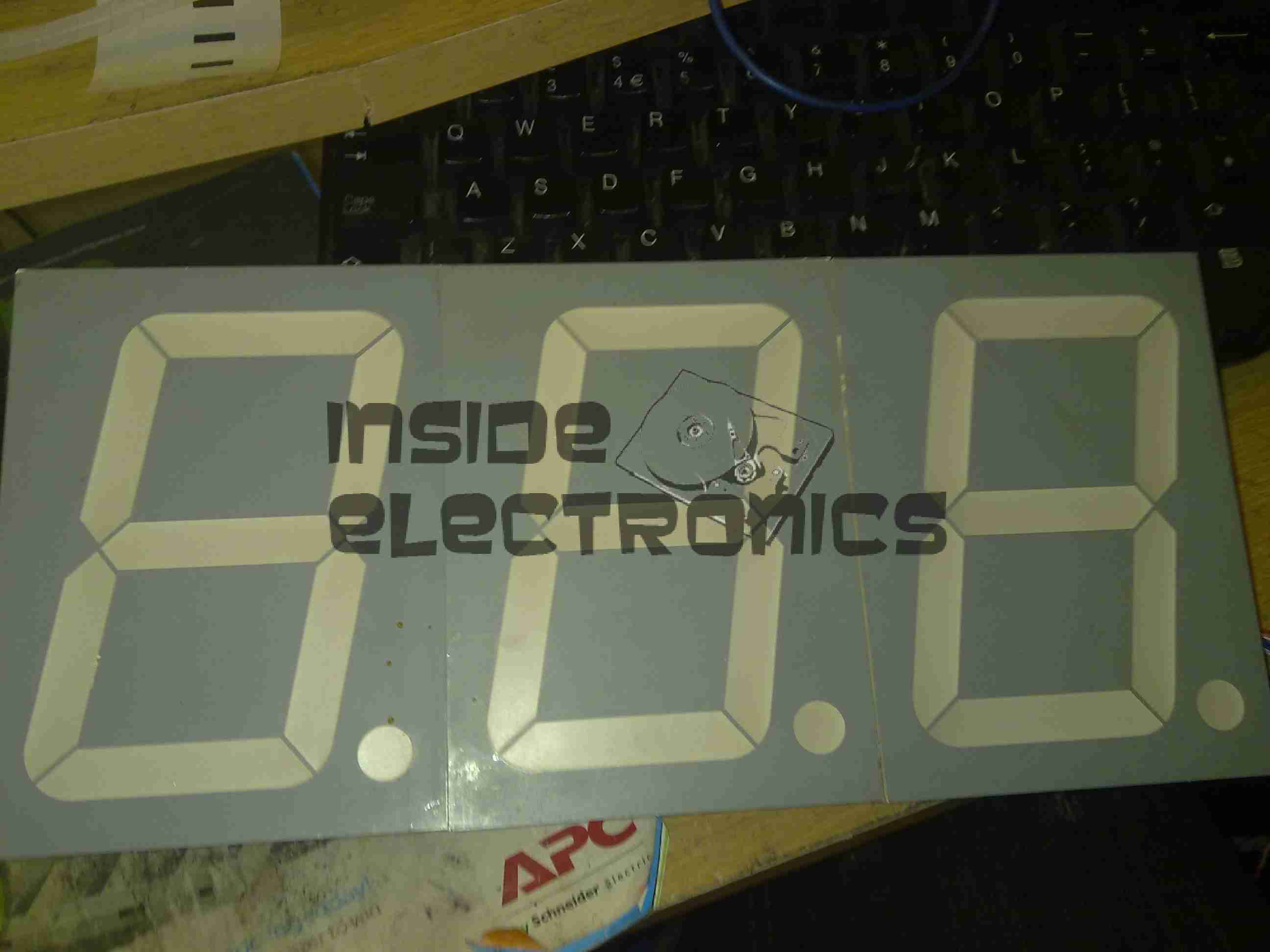
I was recently given some 4″ 7-Segment displays, Kingbright SC40-19EWA & of course, I needed to find a use for them.
I only have three, so a clock isn’t possible…
4″ 7-Segment Display
As these displays are common cathode, & have a ~9v forward voltage on the main segments, some driver circuity is required to run multiplexed from an Arduino.
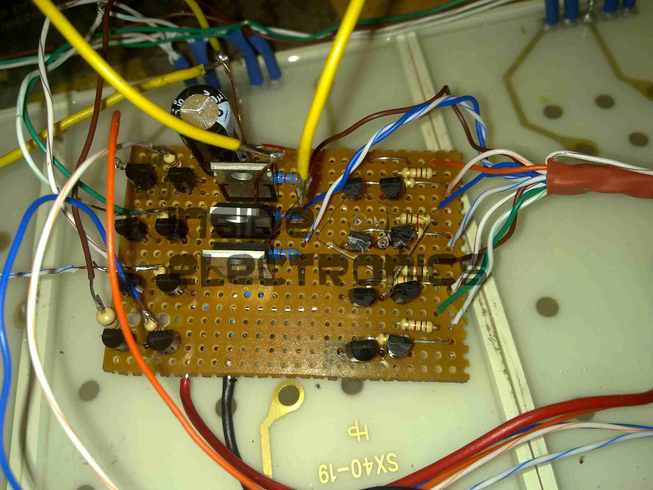
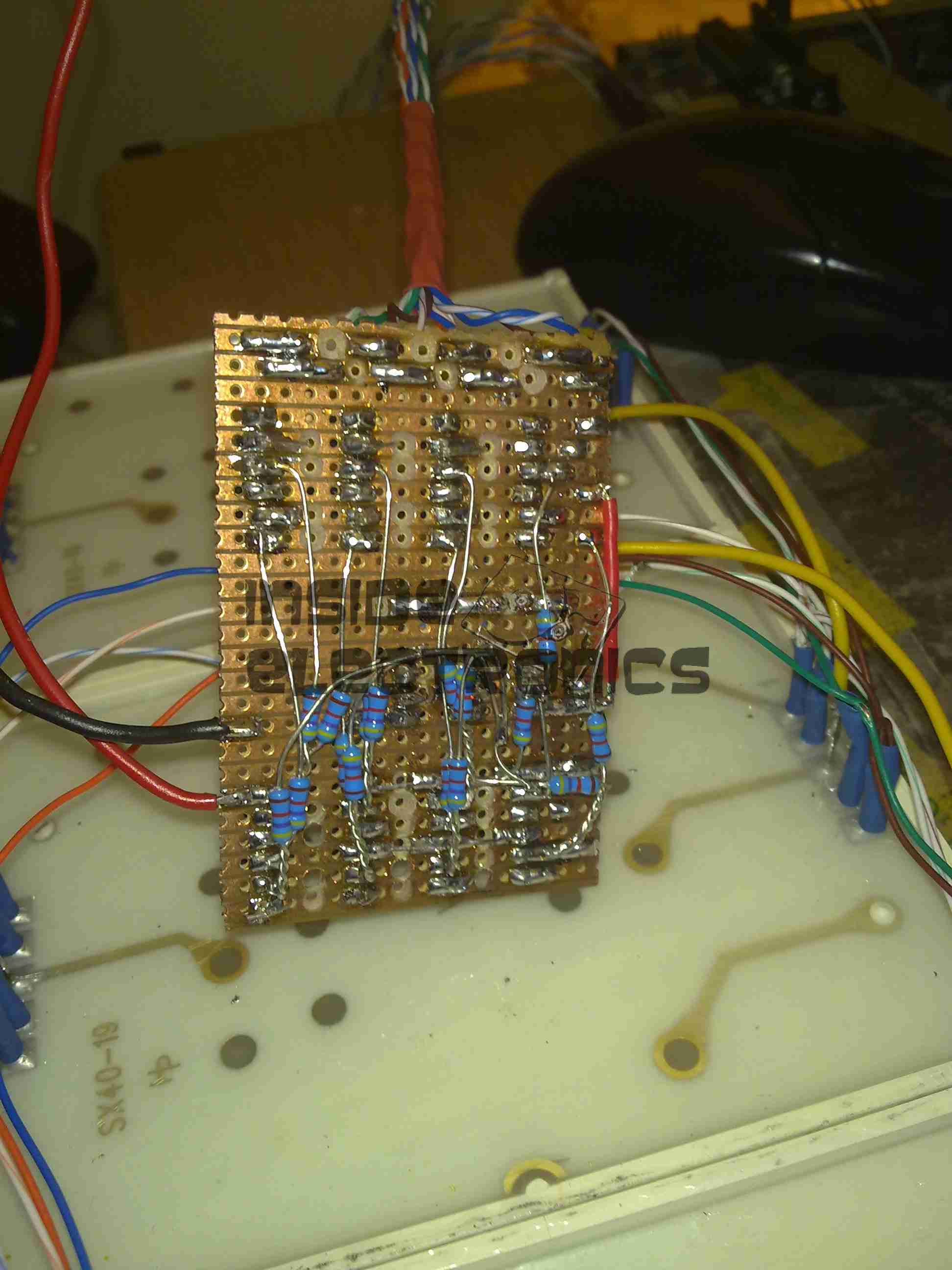
Driver Transistors
Driver circuit built on Veroboard, PNP segment transistors on the left, cathode NPN transistors in the centre, level-shifting NPN array on the right.
Base Bias Resistor Network
Base bias resistors on the back of the board to bias the bases of the segment drive transistors correctly.
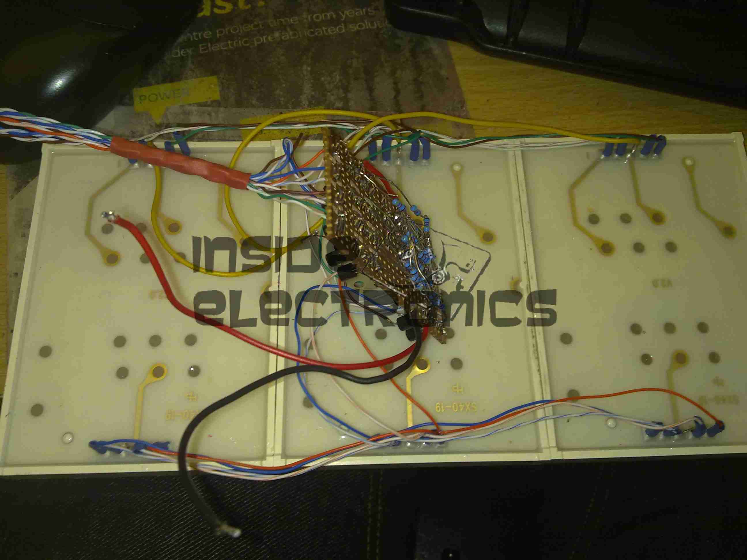
Display Rear
Board soldered into the pins of the displays, which have been multiplexed.
Schematic to come along with some Arduino code to run a room thermometer, with an LM35 sensor
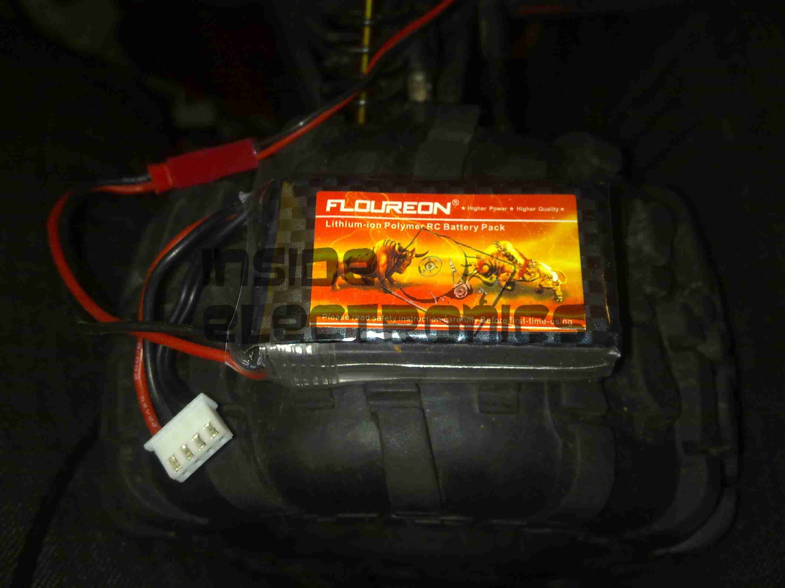
To provide more run time with the conversion to petrol & spark ignition, I have also upgraded the on-board electronics supply to compensate for the extra ~650mA draw of the ignition module.
This modification is centred around a 3S Lithium-Polymer battery pack, providing a nominal 11.1v to a voltage regulator, which steps down this higher voltage to the ~6v required by the receiver & servo electronics.
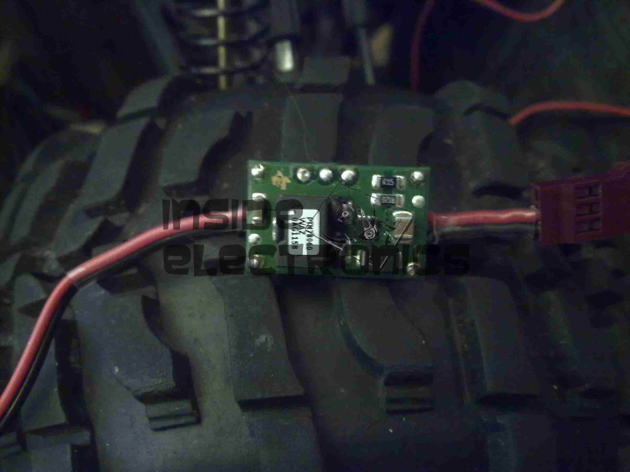
Power RegulatorPower Regulator
The regulator, shown above, is a Texas Instruments PTN78060WAZ wide-input voltage adjustable regulator. This module has an exceptionally high efficiency of ~96% at it’s full output current of 3A. The output voltage is set by a precision resistor, soldered to the back of the module, in this case 6.5v. Standard RC connectors are used on the regulator to allow connection between the power switch & the radio receiver.
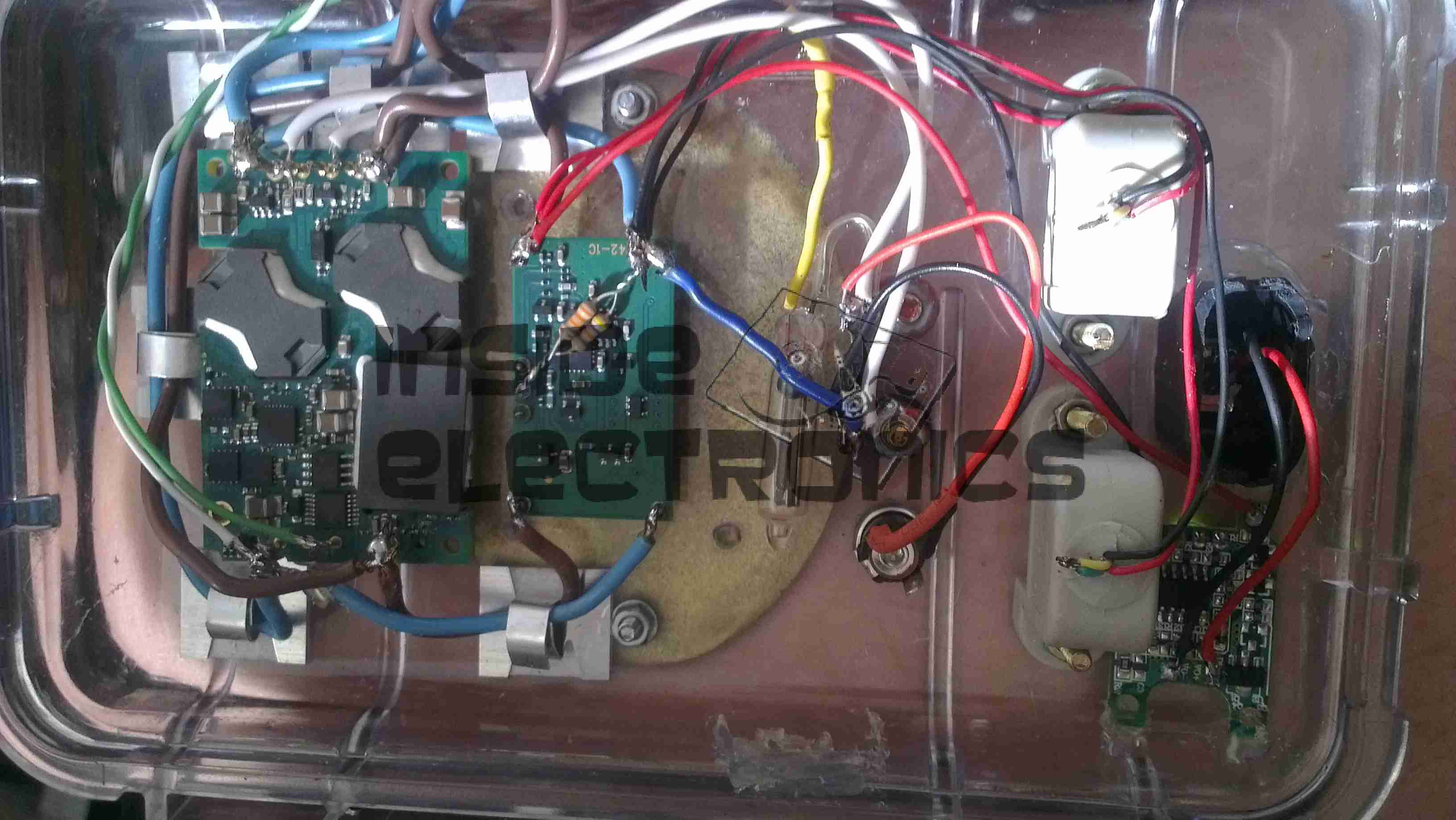
Receiver Box
Everything tucked away into place inside the receiver box. The 3S 1000mAh LiPo fits perfectly in the space where the original Ni-Mh hump pack was located.
The completely stable output voltage of the regulator over the discharge curve of the new battery gives a much more stable supply to the radio & ignition, so I should experience fewer dropouts. Plus the fact that the engine now relies on power from the receiver pack to run, it’s a built in fail safe – if the power dies to the receiver, the engine also cuts out.
While I was already well aware of the effects of petrol on silicone products – the stuff swells up & dissolves over a very short period of time, which makes it an unsuitable material for seals in a petrol fuel system.
Fuel Tank Cap Seal
I wasn’t aware the O-Ring on the fuel tank cap of the Savage is silicone, as can be seen in the image above it has swelled up to much larger than it’s original size. It’s supposed to sit in the groove on the cap & fit into the filler neck when closed.
This was only from a couple of hours of petrol exposure, now the seal is such an ill fit that the cap will not close properly.
The solution here is to replace the ring with a Viton O-Ring, 2.5mm cross section, 23mm ID. I assume the fuel tank is made of polypropylene – this should stand up fine to the new fuel.
Another concern was the O-Rings on the carburettor needles, however these seem to be made of a petrol-resistant material already & are showing no signs of deterioration after 24+ hours of fuel immersion.
The O-Rings that seal the engine backplate to the crankcase also seem to be working fine with the new fuel.
Another silicone part on the engine is the exhaust coupling, between the back of the cylinder & the silencer, I’m not aware of a suitable replacement as yet, although as it will mainly be exposed to the combustion products & not raw fuel, it may just survive the task.
Exhaust Coupling
The extra heat from burning petrol in one of these engines may also put a lot of stress on this component, if it eventually fails I may attempt a replacement with automotive hose – time will tell on this one.
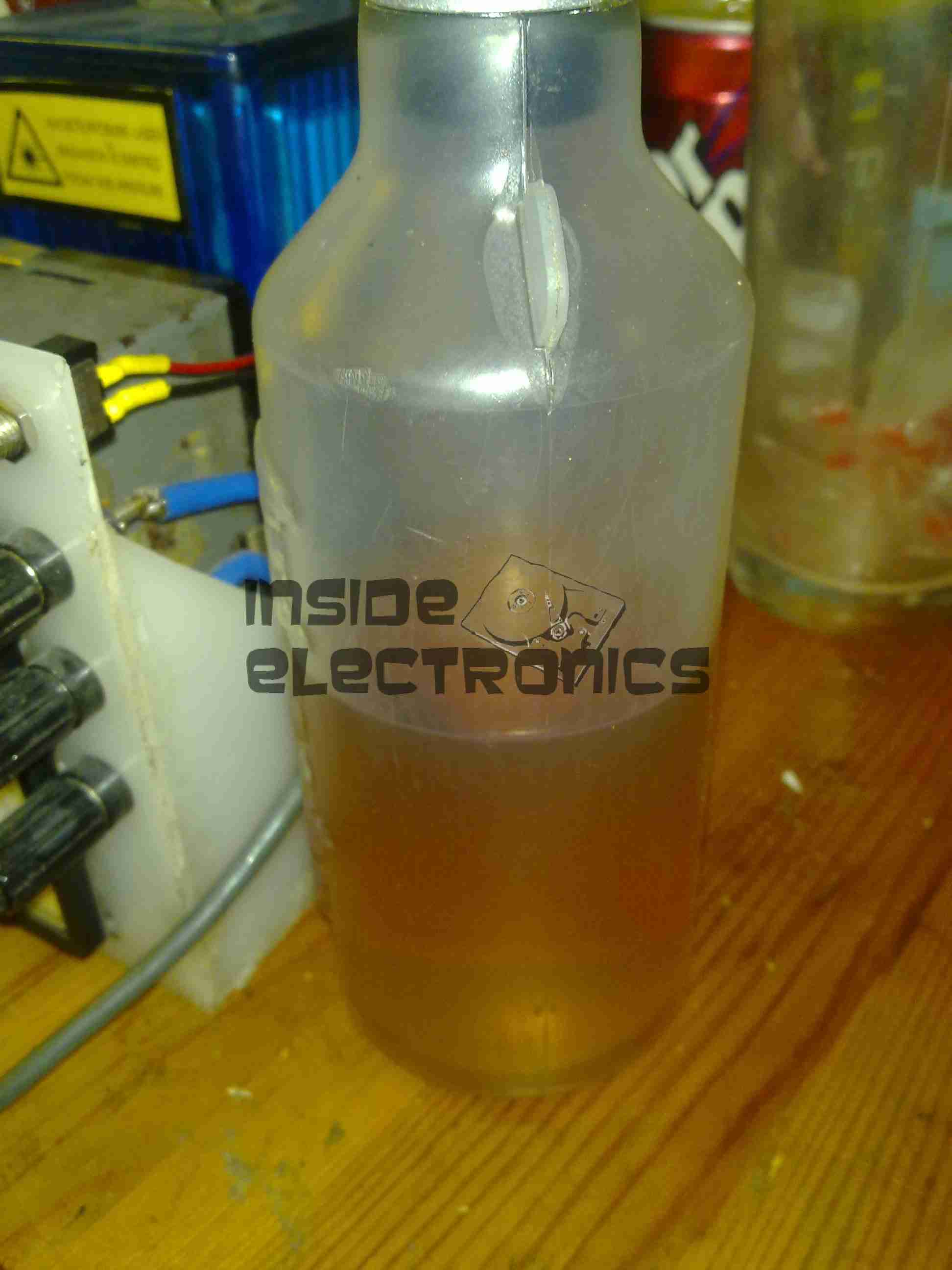
Fuel Bottle
I’m also not sure of the plastic that standard fuel bottles are made from – their resin identification number is 7, so it could be any special plastic, but I’m guessing it’s Nylon.
However according to the spec sheet for Nylon, it’s chemically compatible with petrol – yet the plastic appears to be getting softer with exposure, so it may be a special blend designed specifically for glow fuel.
Besides these small glitches, the engine is running well on it’s newly assigned diet of petrol, I’m currently running an 18:1 mix of petrol to oil (250ml oil to 4.5L of petrol), this seems to be providing more than adequate lubrication. While it smokes like a chimney, plenty of unburned oil is making it out of the exhaust, so the engine’s internals should have a liberal coating.
I’m yet to actually run the model out in open space so I can start tuning the mixture, but bench tests are promising.
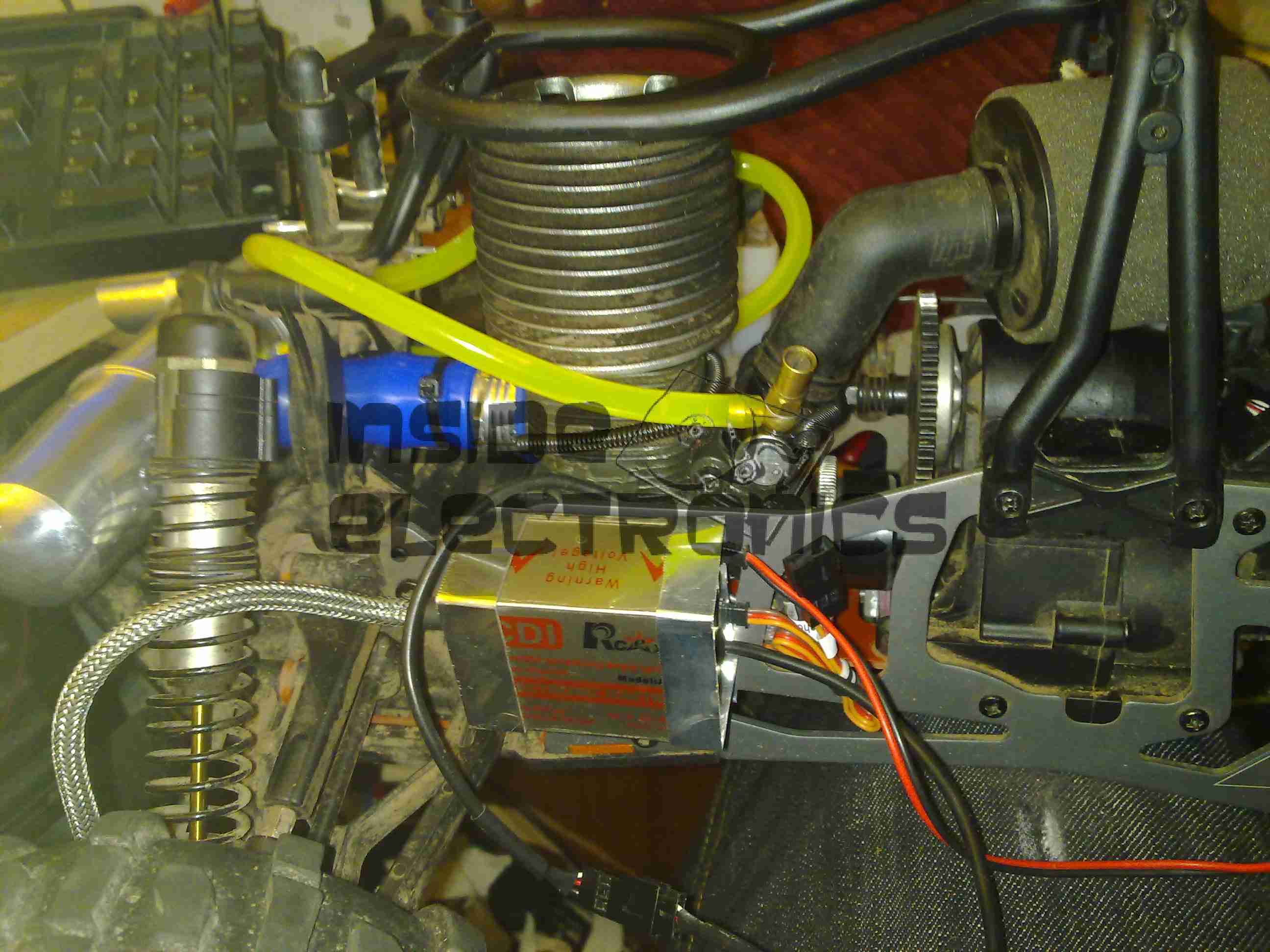
The engine now with it’s required ignition sensor, it is now mounted back on the chassis of the model. I have replaced the stock side exhaust with a rear silencer, so I could fit the ignition module in place next to the engine.
For the mounting, I fabricated a pair of brackets from 0.5mm aluminium, bent around the module & secured with the screws that attach the engine bed plate to the TVPs. The ignition HT lead can be routed up in front of the rear shock tower to clear all moving suspension parts, with the LT wiring tucked into the frame under the engine.
In this location the module is within the profile of the model chassis so it shouldn’t get hit by anything in service.
Rear Exhaust
New exhaust silencer fitted to the back of the model. This saves much space on the side of the model & allows the oily exhaust to be discharged away from the back wheel – no more mess to wipe up.
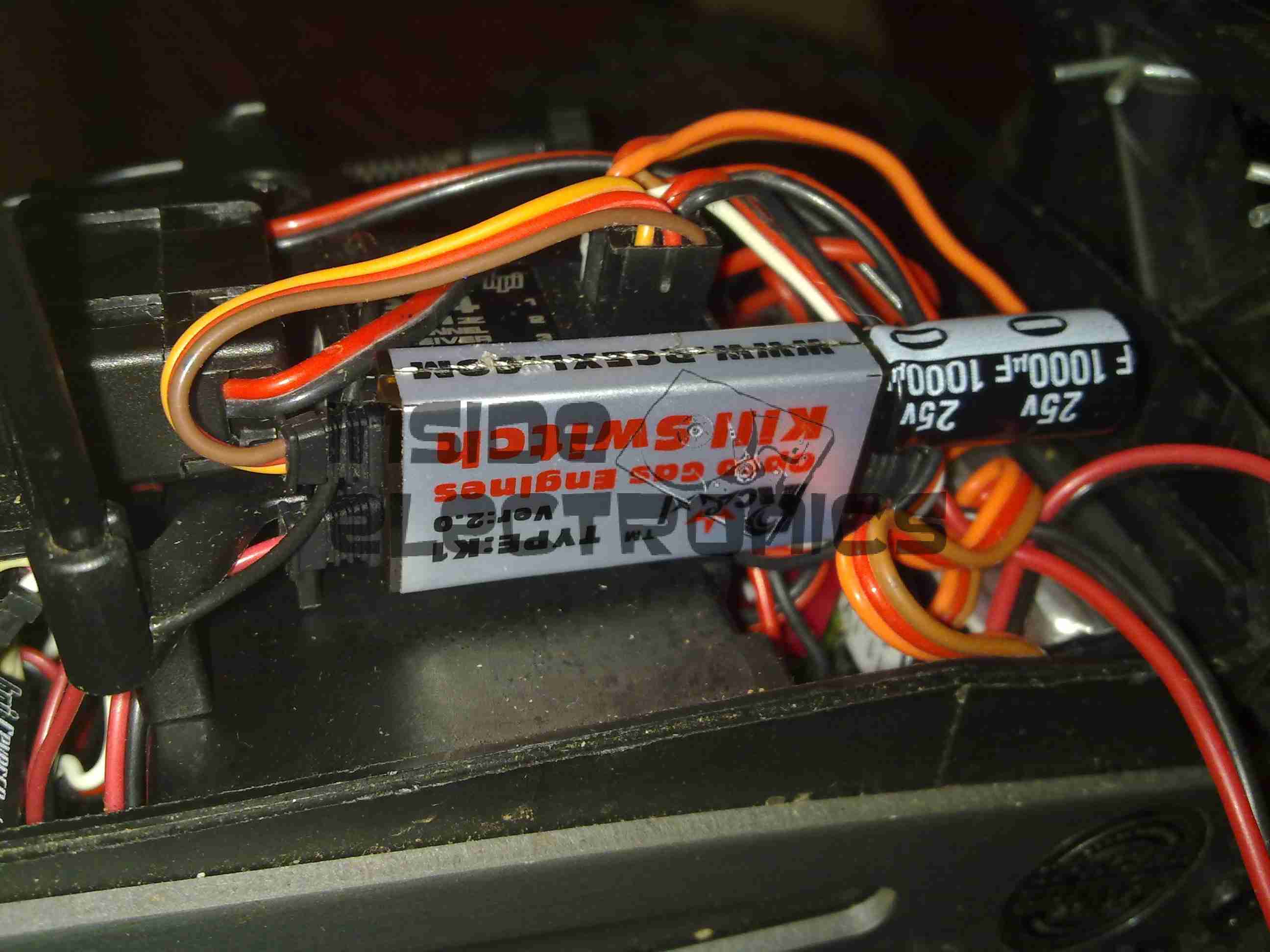
Kill Switch
The ignition switch fitted into the receiver box. This is wired into channel 3 of the TF-40 radio, allowing me to remotely kill the engine in case of emergency. I have fitted a 25v 1000µF capacitor to smooth out any power fluctuations from the ignition module.
The radio is running from a 11.1v 1Ah 3S LiPo pack connected to a voltage regulator to give a constant 6.5v for the electronics. I found this is much more reliable than the standard 5-cell Ni-MH hump packs.
Fuel Tank
The stock silicone fuel tubing has been replaced with Tygon tubing to withstand the conversion to petrol.
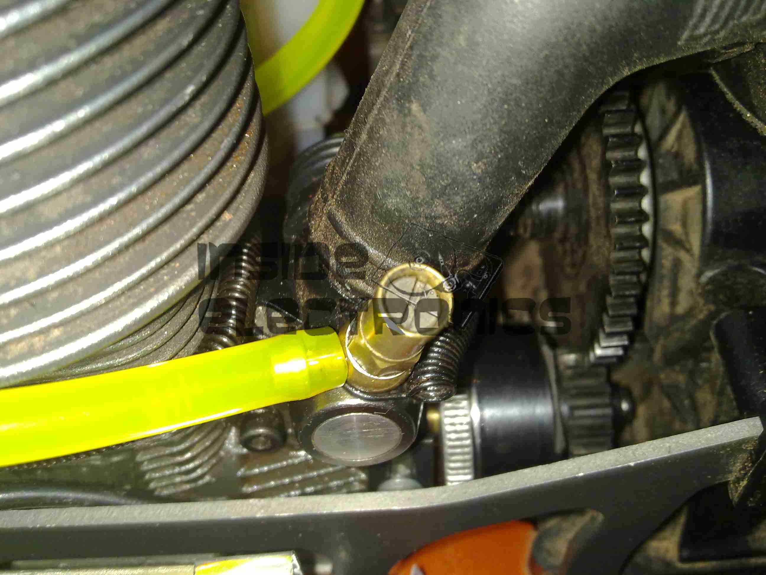
High Speed Needle
High speed needle tweaked to provide a basic running setting on petrol. This is set to ~1.5mm below flush with the needle housing.
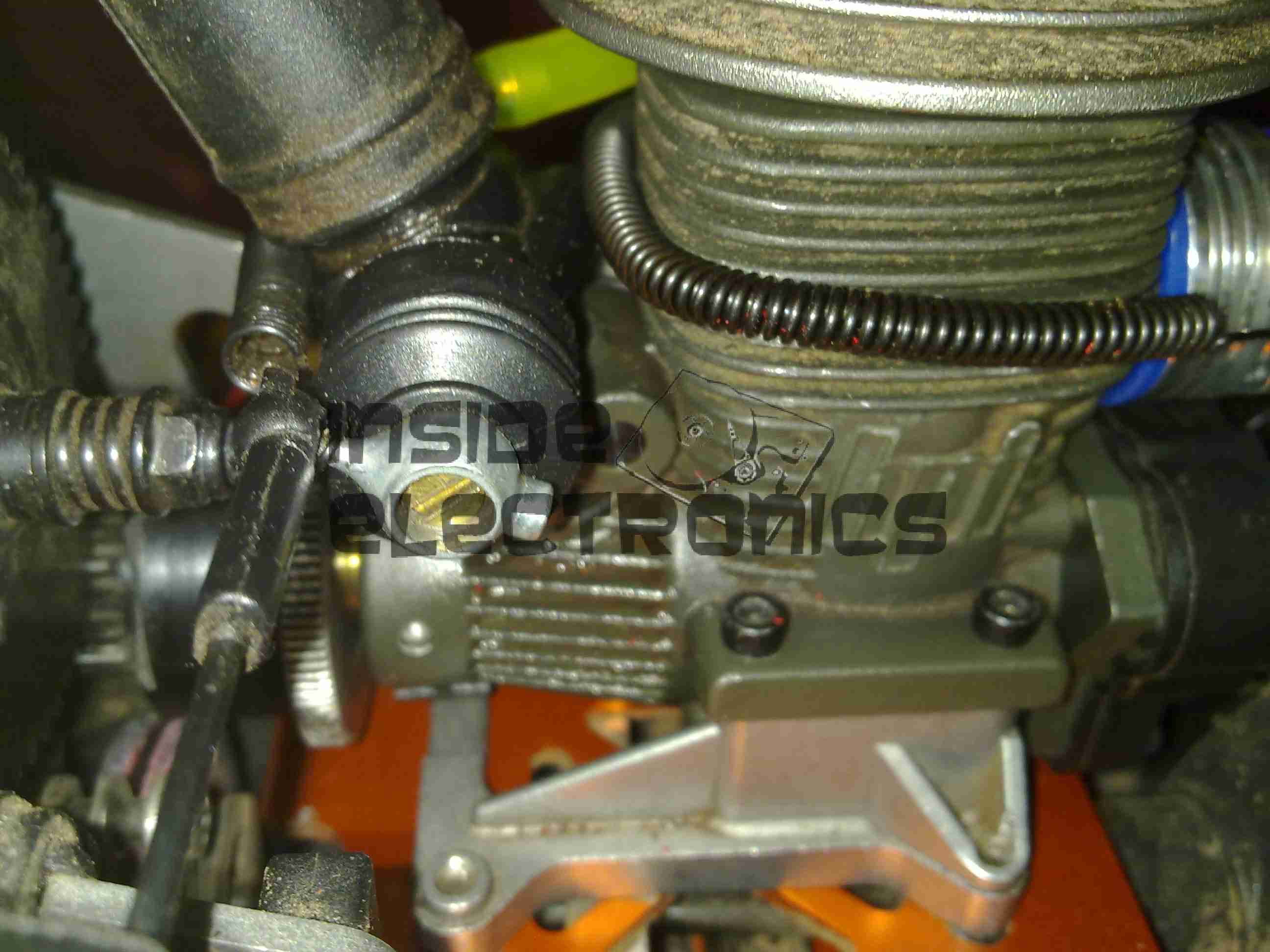
Low Speed Needle
Low speed needle tweaked to provide a basic running setting on petrol. This is set to ~1.73mm from flush with the needle housing.
As petrol is a much higher energy density fuel, it requires much more air than the methanol glow fuel – ergo much leaner settings.
The settings listed should allow an engine to run – if nowhere near perfectly as they are still rather rich. It’s a good starting point for eventual tuning.
As there was no other online example of someone converting a glow/nitro car engine onto CDI ignition, I thought I would document the highlights here.
The engine is currently still running on glow fuel, but when the required fuel lines arrive I will be attempting the switch over to 2-Stroke petrol mix. This should definitely save on fuel costs.
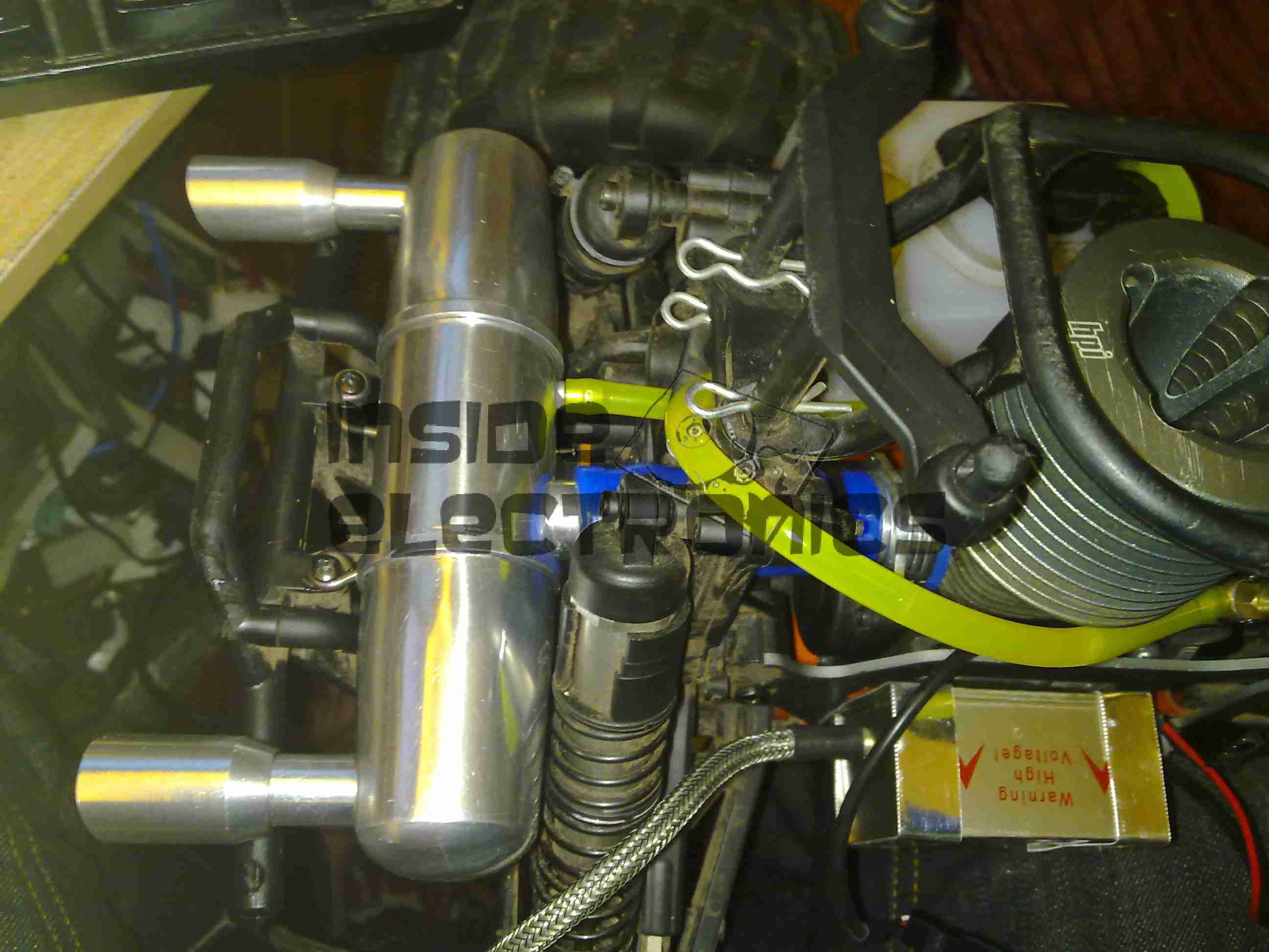
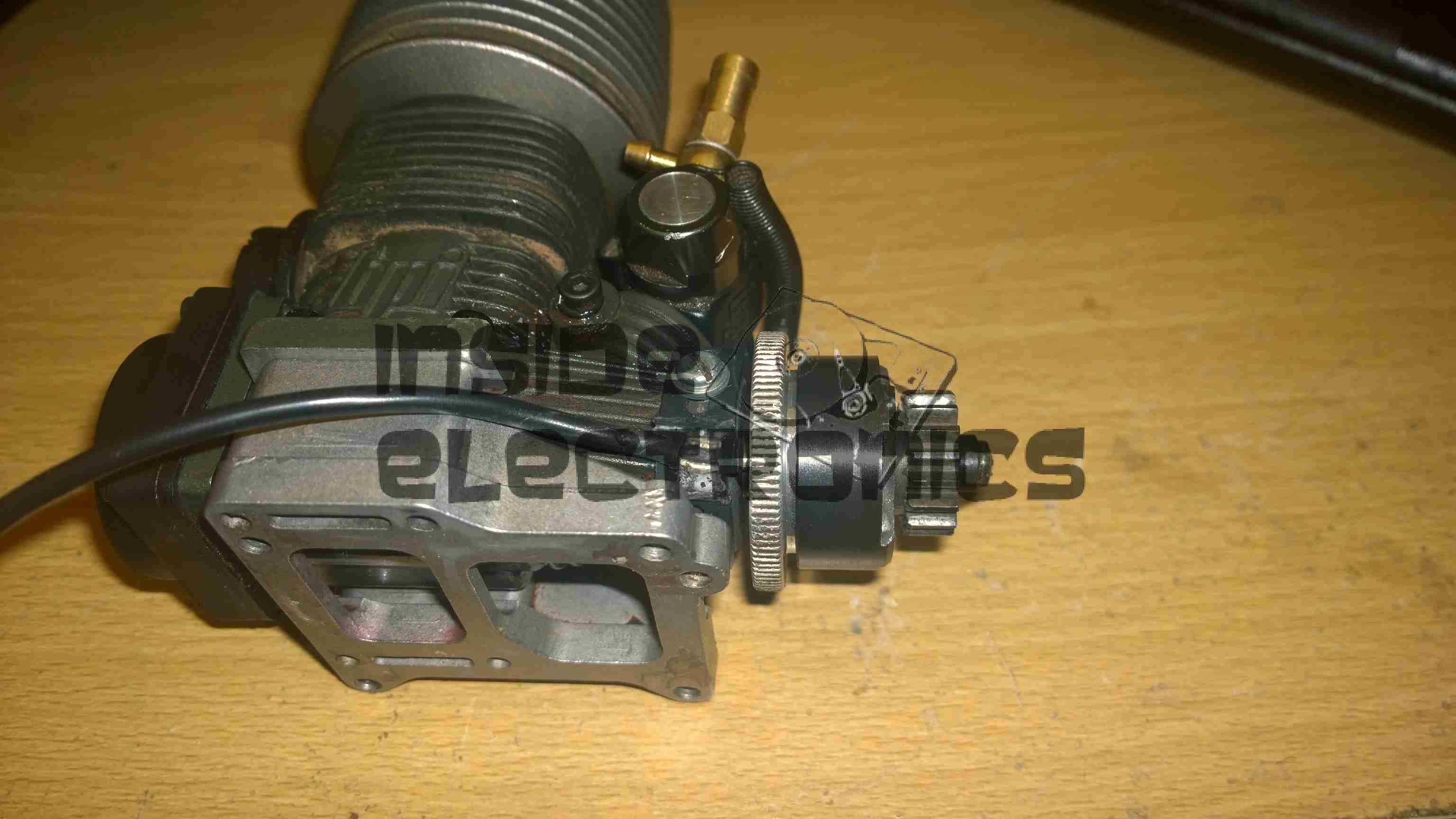
The engine in this case is a HPI NitroStar F4.6 nitro engine, from a HPI Savage X monster truck.
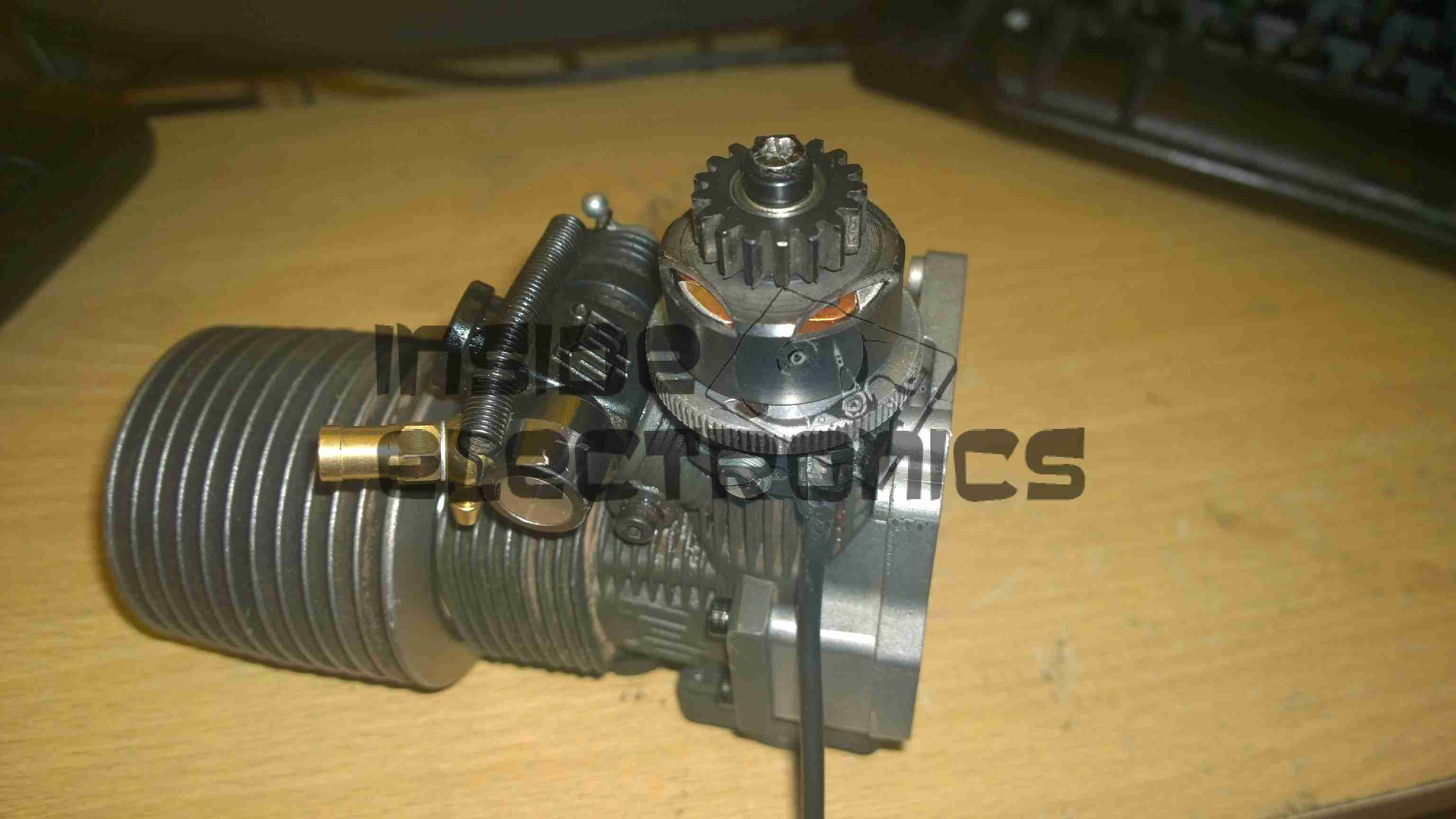
F4.6 Engine
Above is the converted engine with it’s timing sensor. As The installation of this was pretty much standard, a complete strip down of the engine was required to allow the drilling & tapping of the two M3x0.5 holes to mount the sensor bracket to. The front crankshaft bearing has to be drifted out of the crankcase for this to be possible.
Ignition Hall Sensor
Detail of the ignition hall sensor. The bracket has to be modified to allow the sensor to face the magnet in the flywheel. Unlike on an Aero engine, where the magnet would be on the outside edge of the prop driver hub, in this case the hole was drilled in the face of the flywheel near the edge & the magnet pressed in. The Hall sensor is glued to the modified bracket with the leads bent to position the smaller face towards the back of the flywheel.
The clearance from the magnet to sensor is approx. 4mm.
Flywheel Magnet
Detail of the magnet pressed into the flywheel. A 3.9mm hole was drilled from the back face, approx 2mm from the edge, & the magnet pressed into place with gentle taps from a mallet & drift, as I had no vice to hand.
Initial timing was a little fiddly due to the flywheel only being held on with a nut & tapered sleeve, so a timing mark can be made inside the rear of the crankcase, across the crank throw & case to mark the 28 degree BTDC point, the flywheel is then adjusted to make the ignition fire at this point, before carefully tightening the flywheel retaining nut to ensure no relative movement occurs.
The slots in the sensor bracket allow several degrees of movement to fine adjust the timing point once this rough location has been achieved.
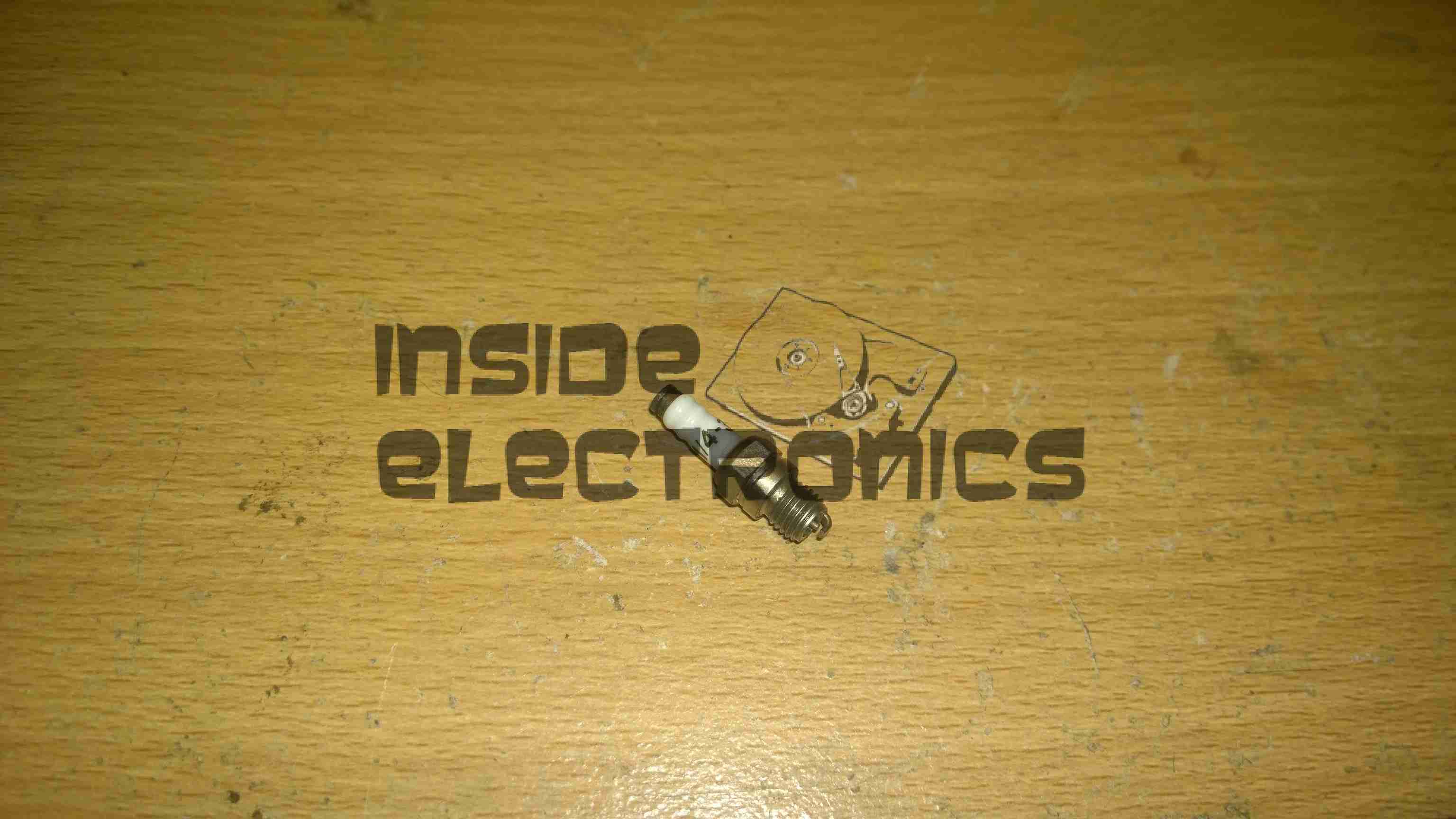
1/4″-32 Spark Plug
Definitely the tiniest spark plug I’ve ever seen, about an inch long. Some trouble may be encountered with this on some engines – the electrodes stick out about 2mm further into the combustion chamber than a standard glow plug does. This causes the ground electrode to hit the top of the piston crown. (This happens on the HPI NitroStar 3.5 engine). The addition of another copper washer under the plug before tightening should cure this problem.
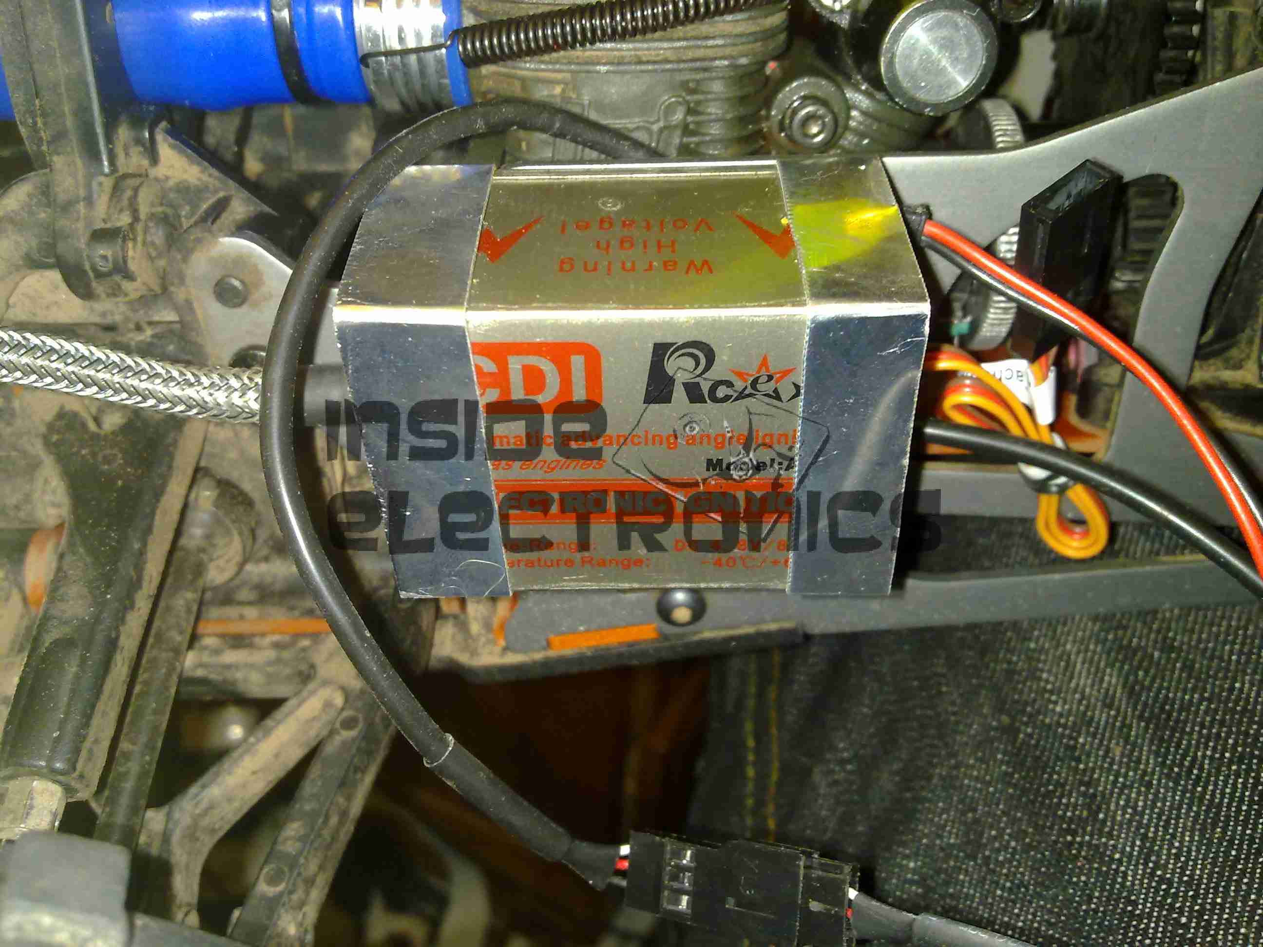
RcExl CDI Ignition Module
Ignition module. Due to the depth of the plug in the heatsink head on these engines, I will have to modify the plug cap to straighten it out, as it will not fit in this configuration.
However, ignition modules are available from HobbyKing with straight plug caps, this makes modification unnecessary
The ignition & components used on this system were obtained from JustEngines.
Just a short script to directly print files to the NCR 7197 Series printers under Linux as there is no direct driver. Certainly not finished or pretty, but functional.
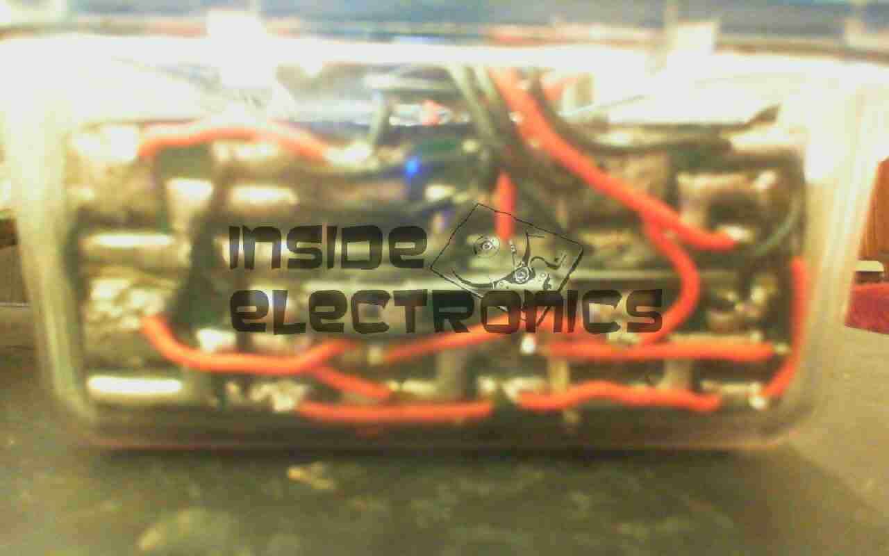
After 13 months of very heavy use at various events, festivals & boat trips, the Li-Po battery pack at the heart of my portable power supply has died.
What initially started as one cell inflating spread to the other cells in the pack over a period of about 3 months, so I have completely replaced the pack with a larger unit.
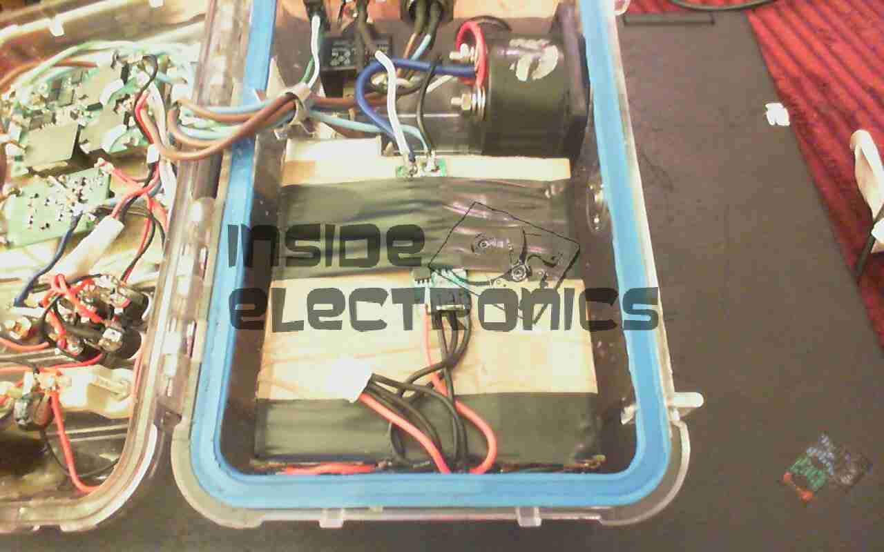
New Pack
The old pack was an 8.8Ah unit at 12.6v. By using smaller burst capacity cells, I have managed to squeeze in a total of 13.2Ah, still leaving space to spare for an extra 3 cell string along the top.
Cell Interconnects
Here is the end of the battery pack, with all the cell interconnects. There are 3 2.2Ah cells in series to give the 12.6v terminal voltage, with 6 of those strings in parallel to give the total Ah rating.
A new charging circuit will be implemented to better handle the volatile chemistry of Li-Po cells, hopefully this will result in the pack lasting longer than a year!
The new higher capacity will hopefully help with power requirements at future events, still being charged during the day by a 24W solar panel, but at night will have to cope with charging two smartphones, two eCigs & running a few watts of LED lighting.
The trial-by-fire will be this year’s Download Festival in June, when I will be operating off-grid for 6 days.
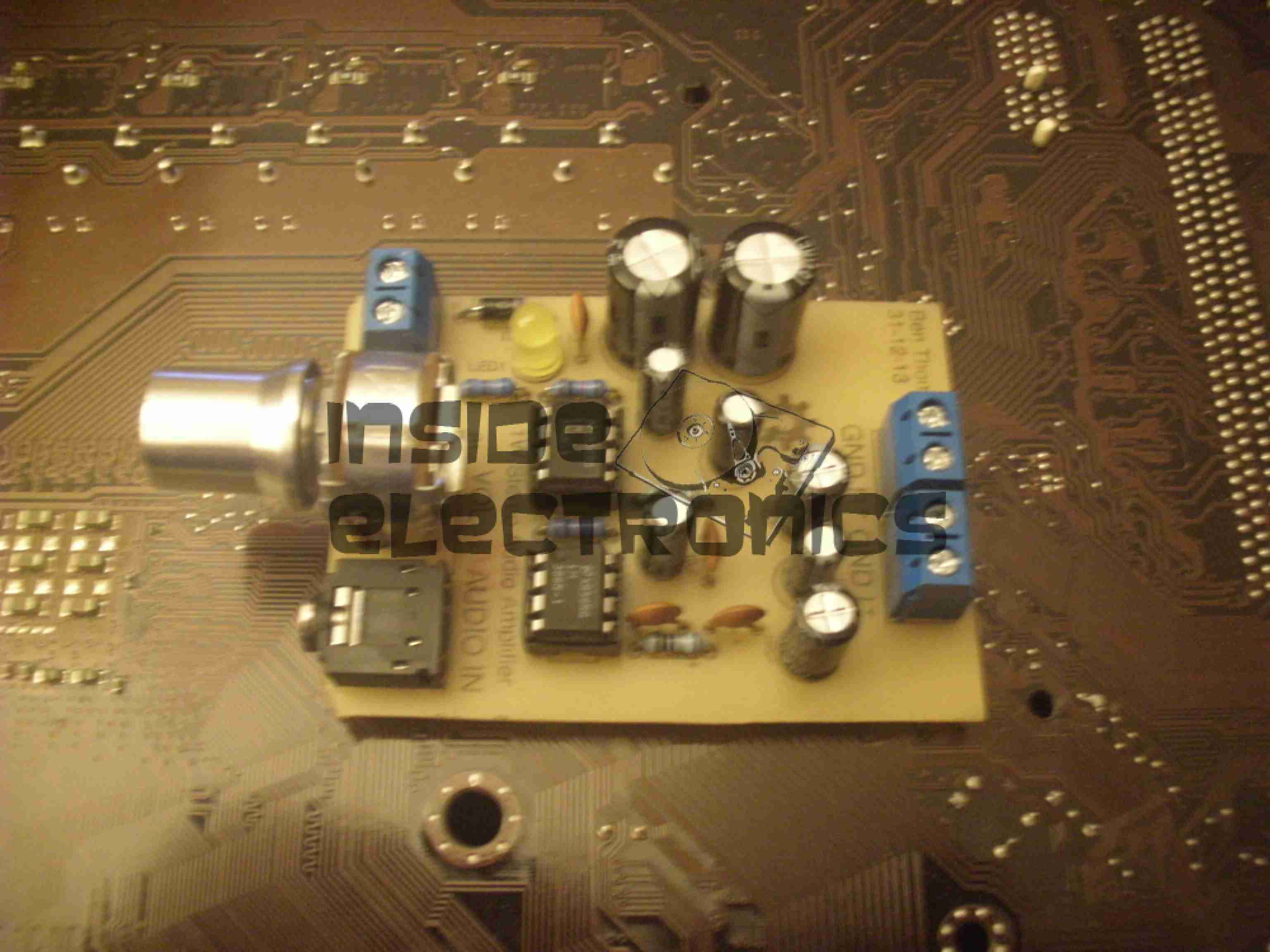
The quickest project from inception to working PCB yet:
From inception to a working PCB took only 4 hours!
LM386 Amplifier
This is a miniature stereo audio amplifier, 0.5W per channel, that can be run from any voltage between 4-12v DC.
As usual, all the Eagle project files are available for download below & kits/bare PCBs will be available for sale for those that cannot etch boards.
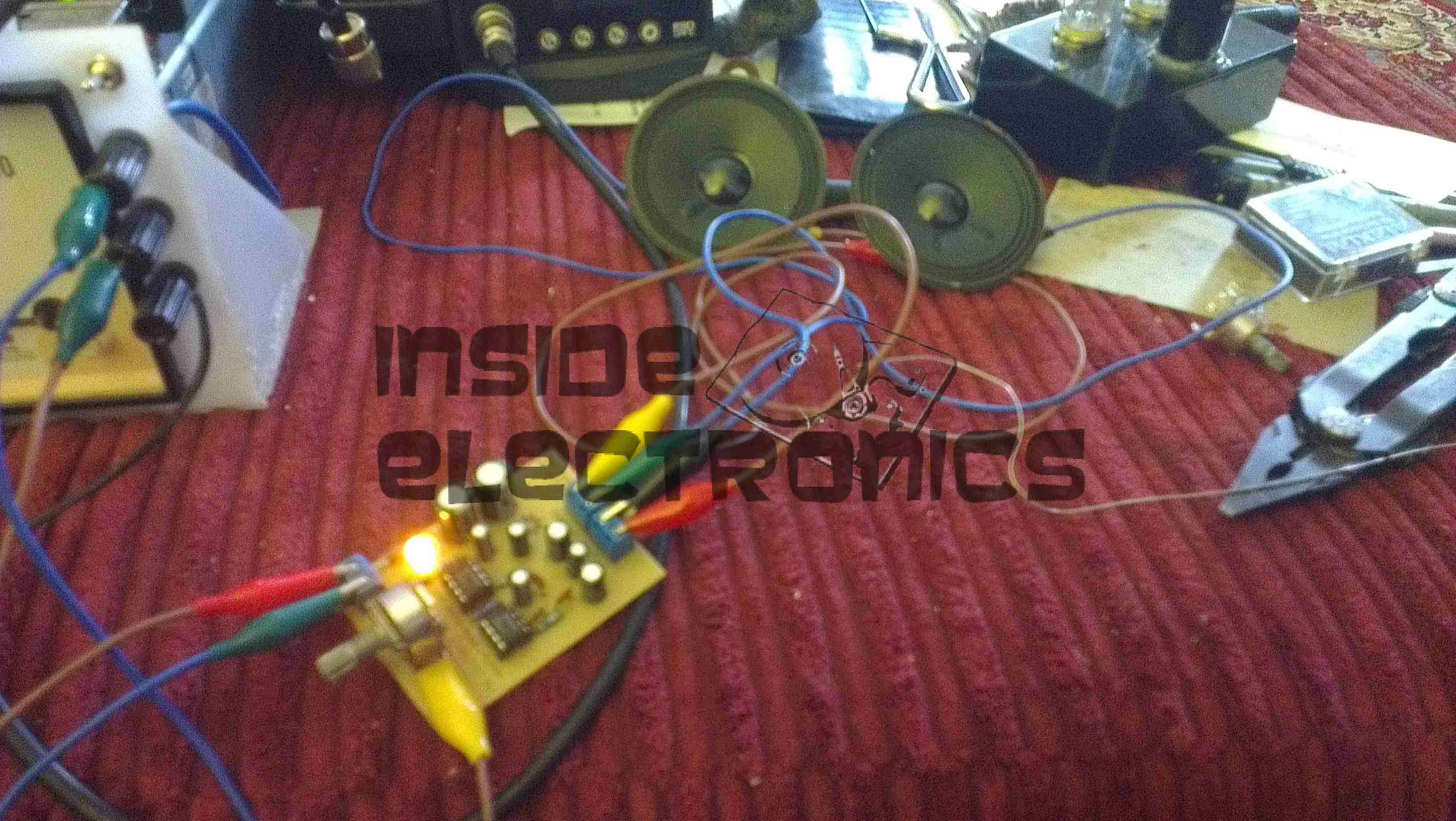
In Operation
Here is the circuit driving a pair of 3W 8Ω speakers from a line level audio source. The gain of this circuit is set at 50 with the components specified.
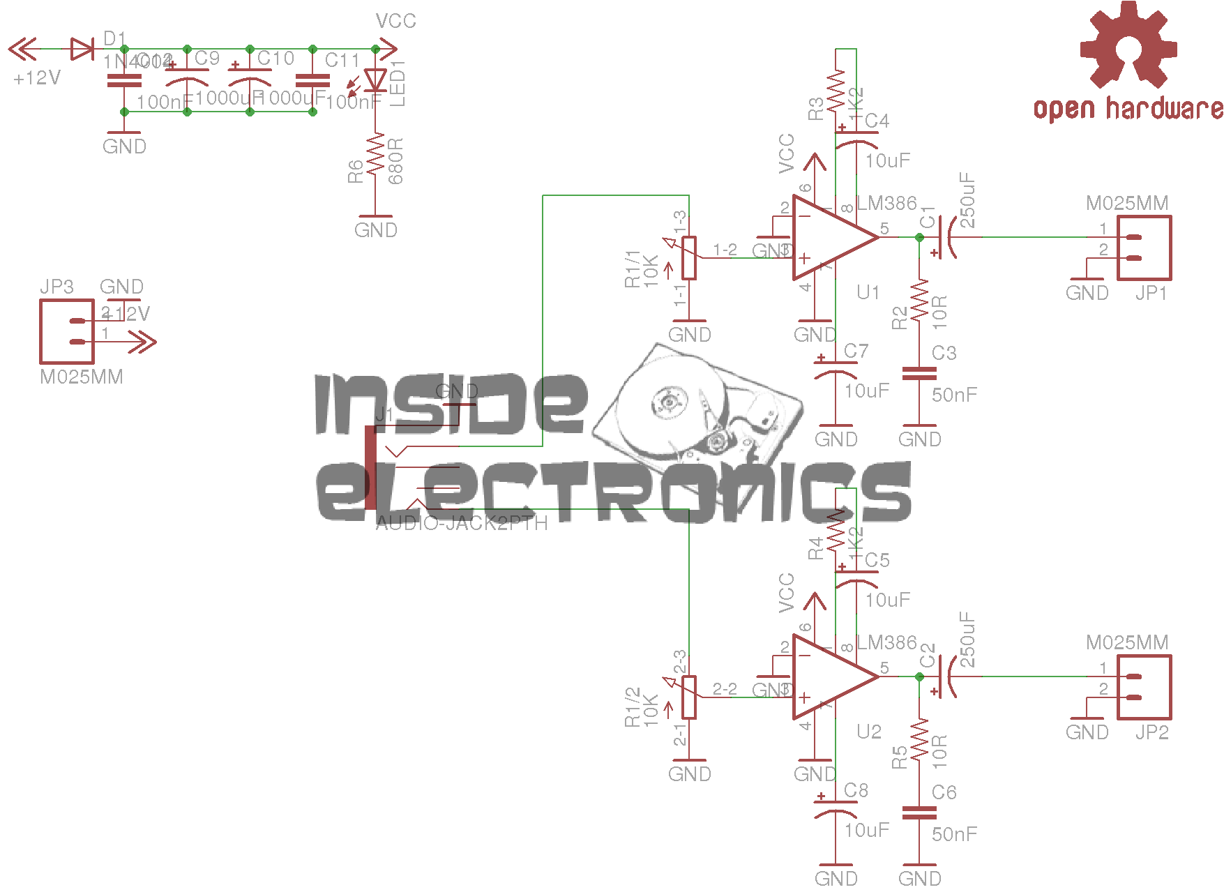
Schematic
As can be seen from the schematic, this is a pair of single LM386 ICs for each channel.
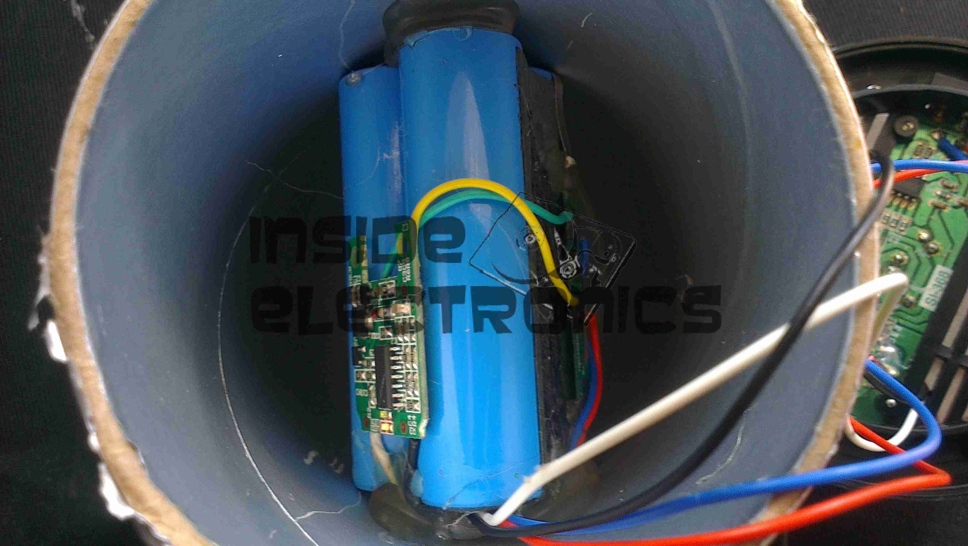
These speakers are available free from Pringles, with two packs bought. Normally running on 3x AAA cells, I have made modifications to include a high capacity Li-Ion battery & USB charging.
18650 Battery
New battery is 3x 18650 Li-Ion cells in parallel, providing ~6600mAh of capacity. These are hot glued inside the top of the tube under the speaker, with the charging & cell protection logic.
The battery charging logic is salvaged from an old USB eCig charger, these are single cell lithium chargers in a small form factor ideal for other uses. Charging current is ~450mA.
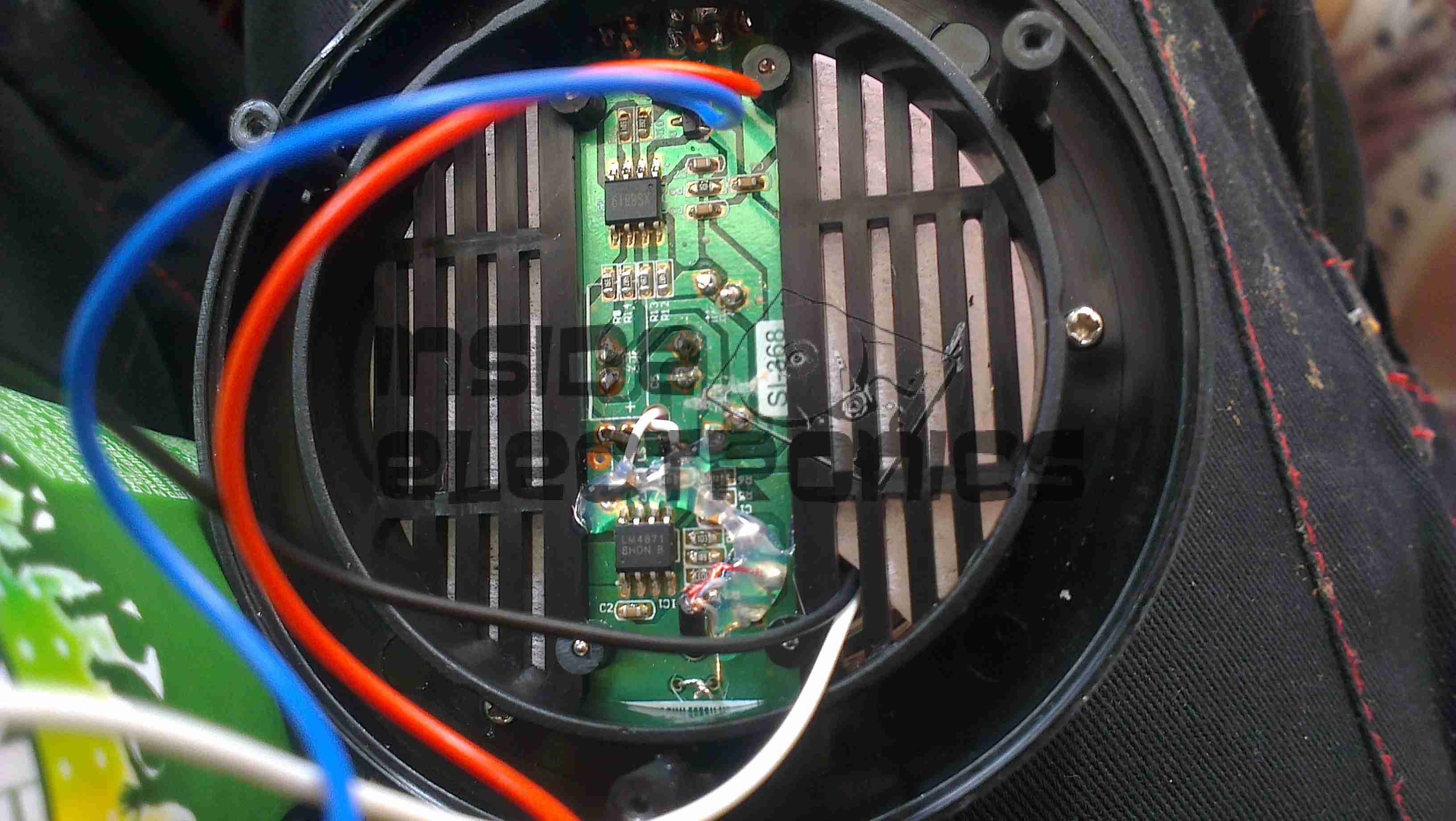
Amplifier Board
The cells are connected to the same points as the original AAA cells, with the other pair of wires going into the top of the device to connect to the MicroUSB charging port.
The amplifier in this is a LM4871 3W Mono amplifier IC, connected to a 6Ω 1W speaker.
The other IC on the board is unidentifiable, but provides the flashing LED function to the beat of the music.
The original LM2577 based regulators I designed into my mobile battery pack turned out to be insufficient for requirements, therefore they have been replaced with higher capacity regulators.
The 12v regulator (left) is a muRata UQQ-12/8-Q12P-C SEPIC converter, providing a max of 8A at 12.1v DC. The 12v rail is also now independently switchable to save power when not in use.
The 5v regulator (right) is a Texas Instruments PTN78020WAZ switching regulator, rated at 6A. The pair of resistors on the back of the regulator set the output voltage to 5.1v.
Also a new addition is a pair of banana sockets & a 2.1mm DC jack, wired into the 12v DC bus, for powering various accessories.
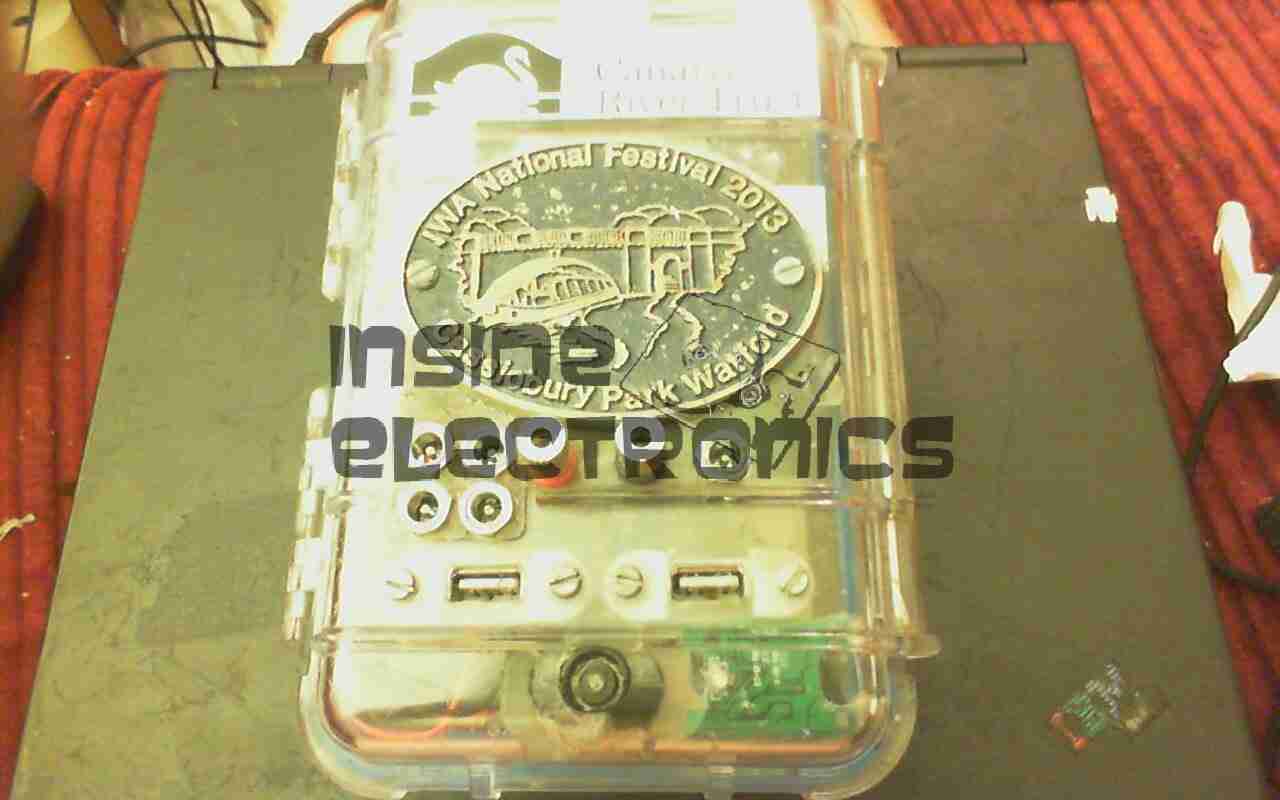
New Additions
Below the USB sockets is now a built in eCig charger, to save on USB ports while charging these devices.
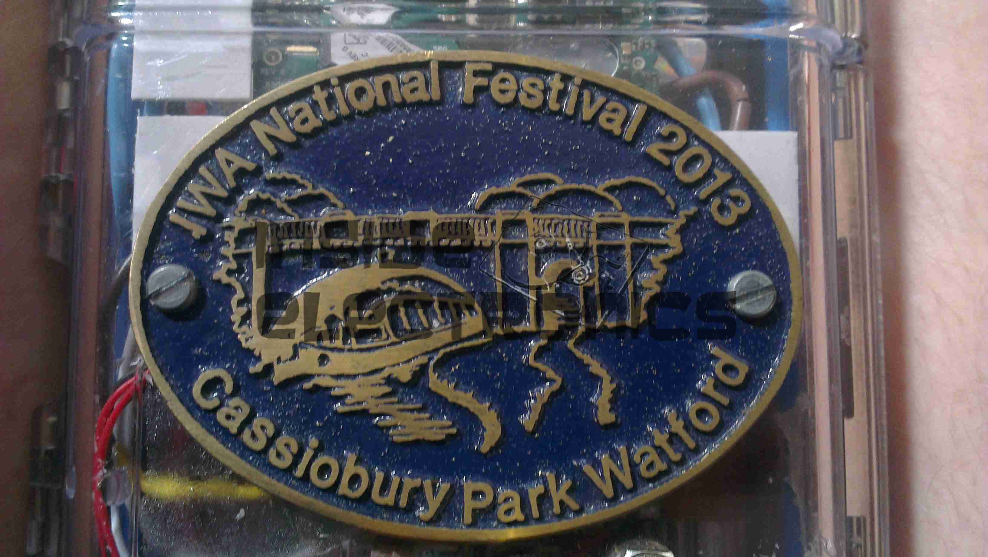
IWA National Festival 2013
These changes were made after much field testing of the unit at Cassiobury Park, Watford, for the IWA National Waterways Festival.
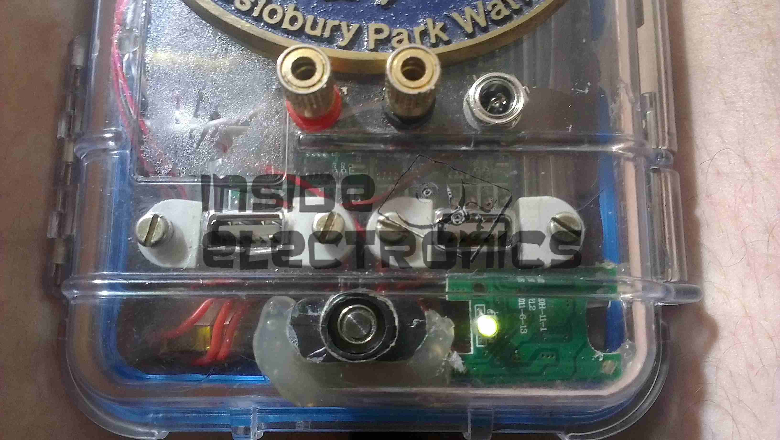
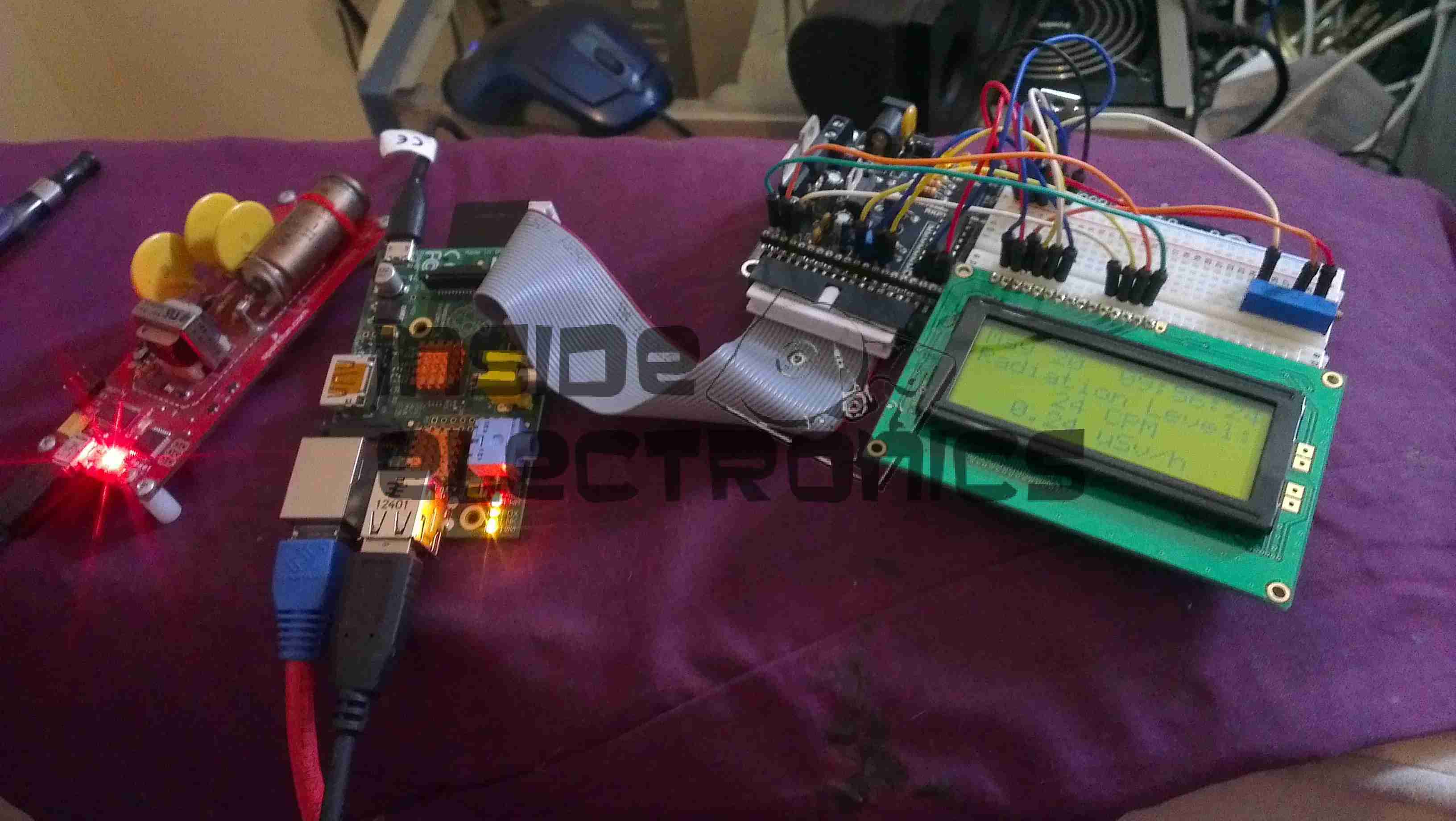
Here’s my latest project with the Pi: interfacing it with the Sparkfun Geiger counter & outputting the resulting data to a character LCD.
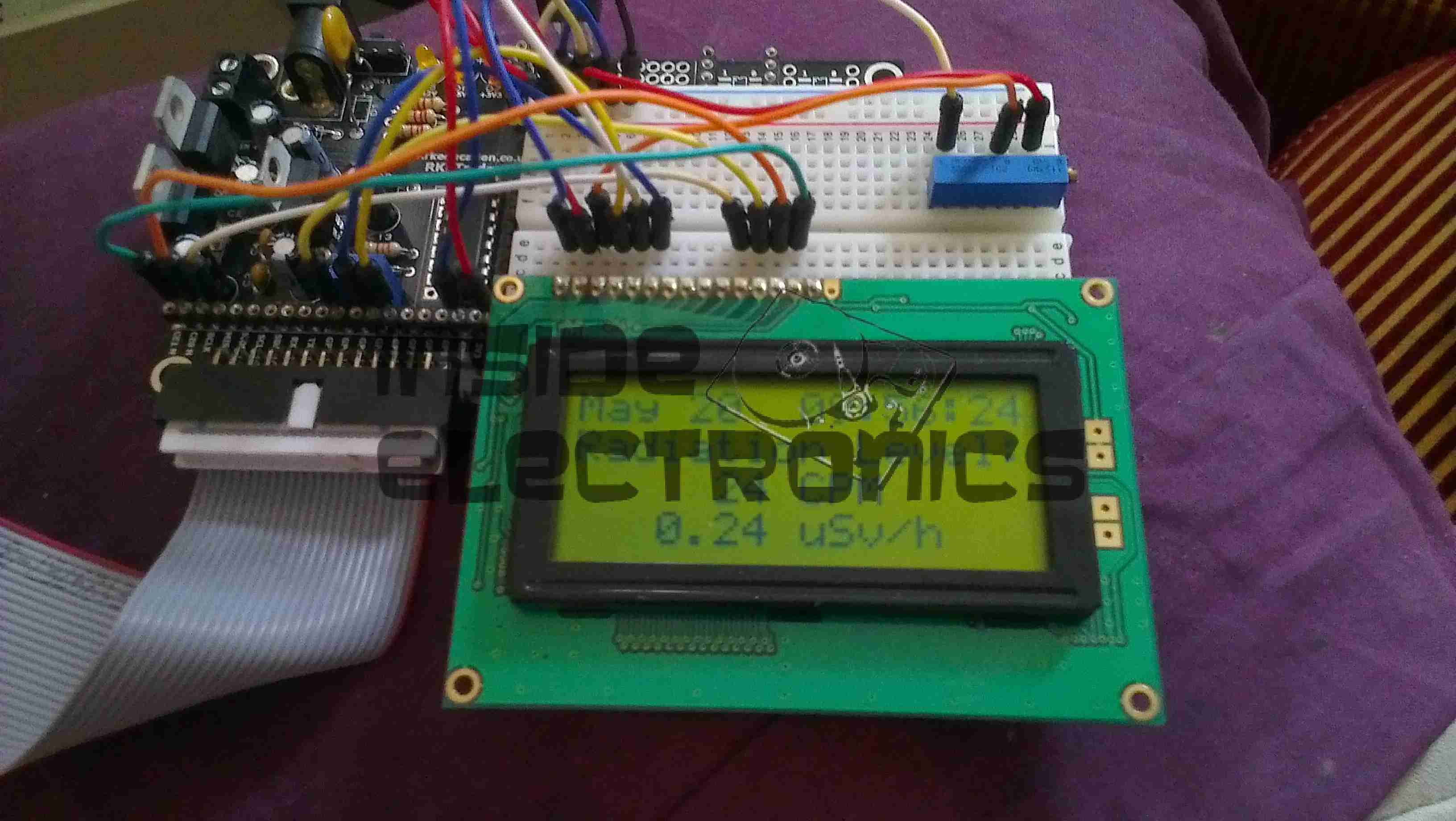
The geiger counter is interfaced with it’s USB port, with the random number generator firmware. A Python script reads from the serial port & every minute outputs CPM & µSv/h data to the display.
The Python code is a mash of a few different projects I found online, for different geiger counters & some of my own customisations & code to write the info to the display & convert CPM into µSv/h.
This also writes all the data into a file at /var/log/radlog.txt
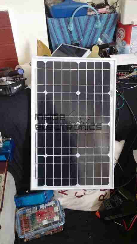
I have acquired a 24W monocrystalline solar panel to charge my portable battery pack while on the move. This panel will be able to charge all devices I carry on a regular basis with nothing but some sunlight!
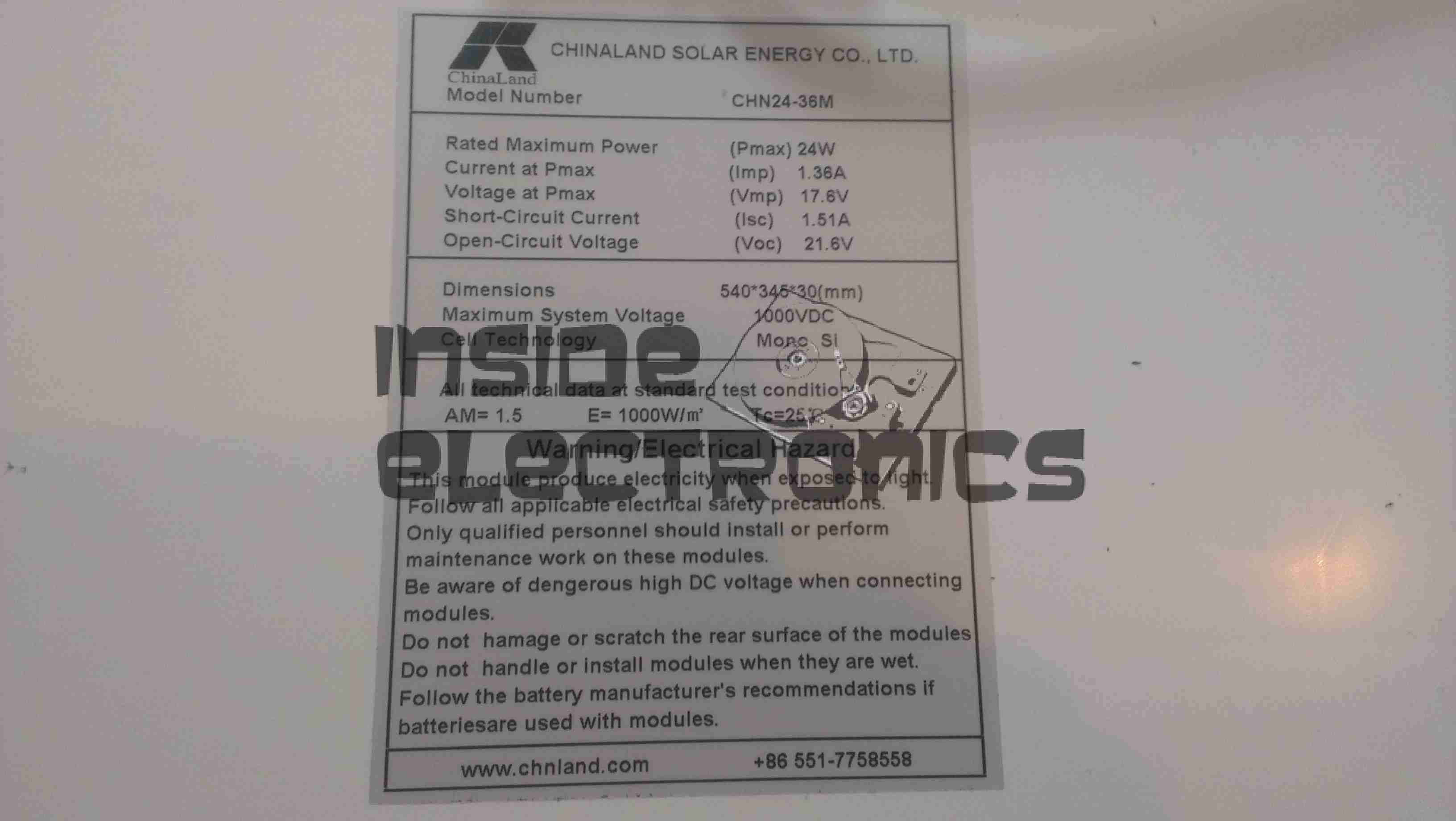
Info Panel
Info on the panel itself. Rated at 24W with nominal 17.6v DC, 1.36A output.
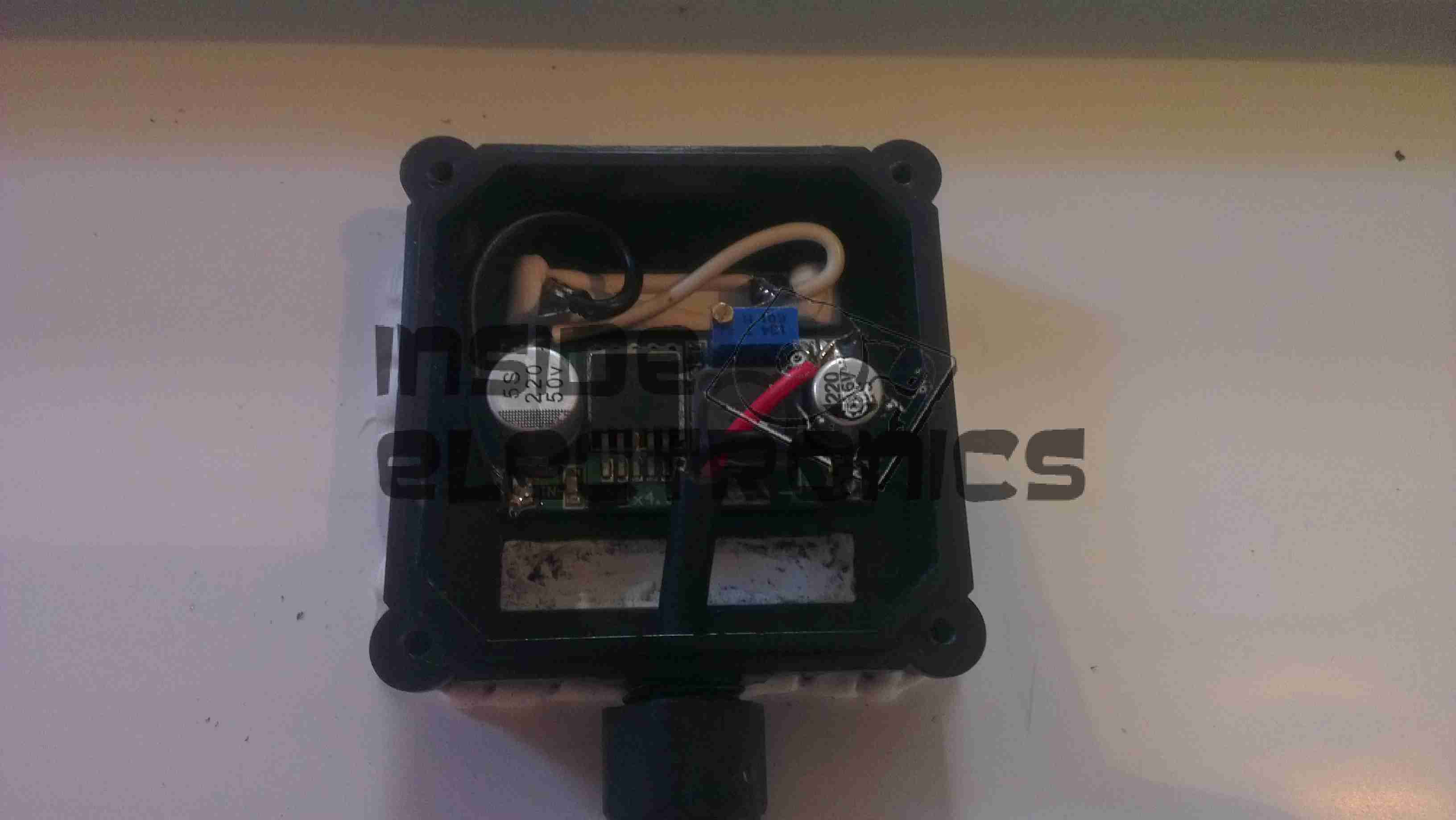
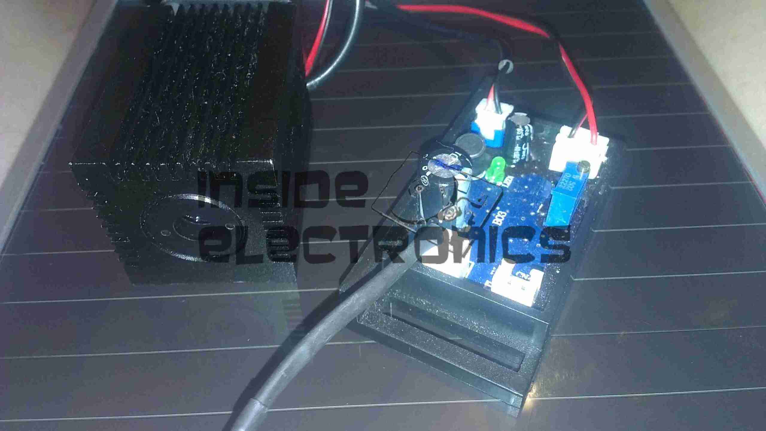
Regulator
I have installed a switching regulator in the back of the panel, where the connections would normally be wired straight to the array of cells. This regulates the voltage down to a constant 13.8v to provide more compatibility with 12v charging equipment. I have tested the output of the panel in late day sun, at 1.27A.
This is a fan cooled 445nm laser module, which emits in the blue part of the spectrum.
Fan cooled & with TTL control built in, this is the beginning of a new laser projector.
Here’s the regulator hooked up with test clips, on the right is the supply from the ultracapacitor bank, while on the left is the output, feeding a 2.3A brushless fan as a test load.
These regulators do get warm, even with no load, with a 2.3A load on the output, the temperature stays warm to the touch.
Here’s something new, an internet connected Geiger counter! The graph in the sidebar is updated once every 60 seconds, and can be clicked on for a larger version. Measurements are in Counts Per Minute, the graph logs 1 hour of data.
The counter itself is a Sparkfun Geiger counter, with the end cap removed from the tube so it can also detect alpha radiation.
Connected through USB, a Perl script queries the emulated serial port for the random 1 or 0 outputted by the counter when it detects a particle. The graph is pretty basic, but it gets the point across. Anybody who wishes to contribute to improve the graphing is welcome to comment!
Here are the first set of mods & improvements to the RasPi Experiment board. Instead of the solder-point experiment space, I have added a standard mini-breadboard, even though it’s a little too long to fit on the board properly.
In the DIP breakout, is a MAX232 TTL-RS232 interface IC, useful for interfacing directly to the Pi’s UART, made available on the GPIO breakout. I will be hardwiring the MAX232 IC into the GPIO port, & fitting headers to the relevant pins on the IC breakout to make interfacing to the Pi easier.
All the MAX232 requires to operate are a 5v supply & 4 1µF capacitors.
The new TO220 device next to the breadboard is a TIP121 darlington power transistor.This is rated at 80v 5A continuous. Useful for driving large loads from a GPIO output.
After seeing these on eBay for £8.99 I thought it might be a good deal – interfacing with the RasPi’s GPIO & it has built in power supplies.
As a kit, it was very easy to assemble, the PCB quality is high, and is a fairly good design. It worked first time, the regulators hold the rails at the right voltages.
However there are some issues with this board that bug me.
The documentation for the kit is *AWFUL*. No mention of the regulators on the parts list & which goes where – I had to carefully examine the schematics to find out those details.
The 4x 1N1007 diodes required weren’t even included in the kit! Luckily I had some 1N4148 high speed diodes lying around & even though they’re rated for 200mA continuous rather than the specified part’s 1A rating, the lack of heatsinking on the regulators wouldn’t allow use anywhere near 1A, so this isn’t much of a problem.
Component numbering on the silkscreen isn’t consistent – it jumps from R3 straight to R6! These issues could be slightly confusing for the novice builder, and considering the demographic of the RasPi, could be seen as big issues.
On the far left of the board are the 5v & 3.3v regulators, well placed on the edge of the board in case a heatsink may be required in the future. However the LM317 adjustable regulator is stuck right in the middle of the PCB – no chance of being able to fit a heatsink, & the device itself seems incredibly cheap – the heatsink tab on the back of the TO-220 is the thinnest I have ever seen. Not the usual 2-3mm thick copper of the 5v & 3.3v parts – but barely more than a mm thick, so it’s not going to be able to cope with much power dissipation without overheating quickly.
As the adjustable rail can go between ~2.5v – 10v, at the low end of the range the power dissipation is going to shoot through the roof.
The GPIO connector – this could have been done the other way, at the moment the ribbon cable has to be twisted to get both the Pi & the GPIO board the same way up. Just a slight fail there. See the image below
Plugged In
The power rails are not isolated out of the box – there is no connection between the 5v & 3.3v rails & the Pi’s GPIO, but the GND connections are linked together on the board.
Getting the ribbon cable through the hole in the ModMyPi case was a bit of a faff – the connector is too big! I had to squeeze the connector through at a 45° angle. The case is also remarkably tight around the connector once it’s fitted to the board – clearly the designers of the case didn’t test the an IDC connector in the case before making them!
Everything does fit though, after a little modification.
All Cased Up
Here is the unit all built up with the case. The top cover just about fits with the IDC connector on the GPIO header.
More to come once I get some time to do some interfacing!
This is just a few notes on the repair of an eCig battery (1Ah Tornado).
These batteries seem to have a flaw in which they will randomly stop working, while still displaying all the normal activity of the battery.
Here is what I have found.
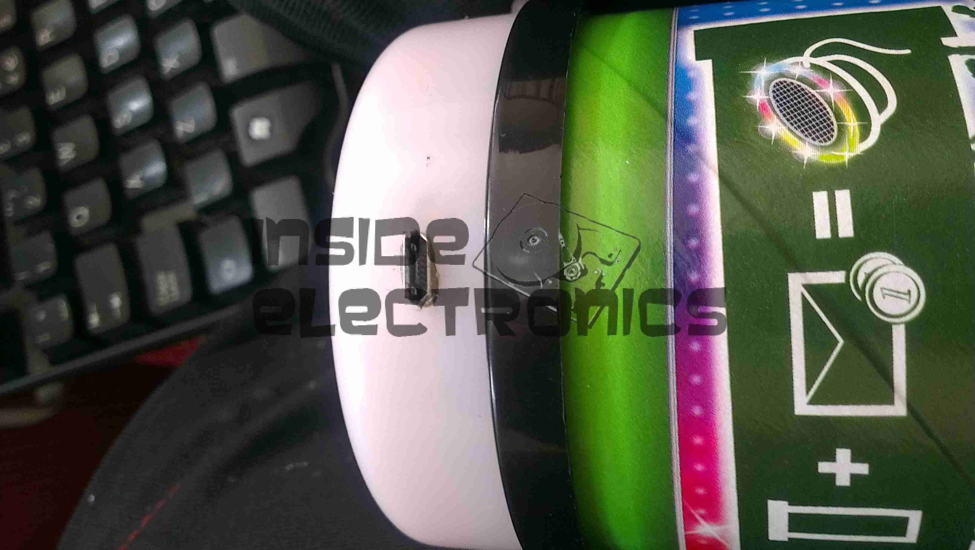
Control PCB
Here the battery has been partially disassembled, with the control circuitry exposed here at the end of the unit. All the wiring here is fine & the electronics themselves are also OK, due to the LEDs still operating as normal when the button is pushed. The 1000mAh Li-Poly cell is to the right.
Ground Wire
Here the end cap has been removed from the opposite end of the battery & the problem is found: the short wire here is the GND return for the atomiser, normally connected to the negative terminal of the battery in the tube, however here it has broken off.
This is most likely due to either the cell moving inside the tube during normal operation, weakening the solder joint, or simply a bad solder job from the factory. (This lead-free ROHS bullshit is to blame).
Repaired
Here the wire has been successfully soldered back on to the battery tab. I have also added a small dab of hot glue to hold the battery in place on the inside of the tube, & replaced the solder on the joints with real 60/40 leaded solder. £15 saved.
Tip Jar
If you’ve found my content useful, please consider leaving a donation by clicking the Tip Jar below!
All collected funds go towards new content & the costs of keeping the server online.