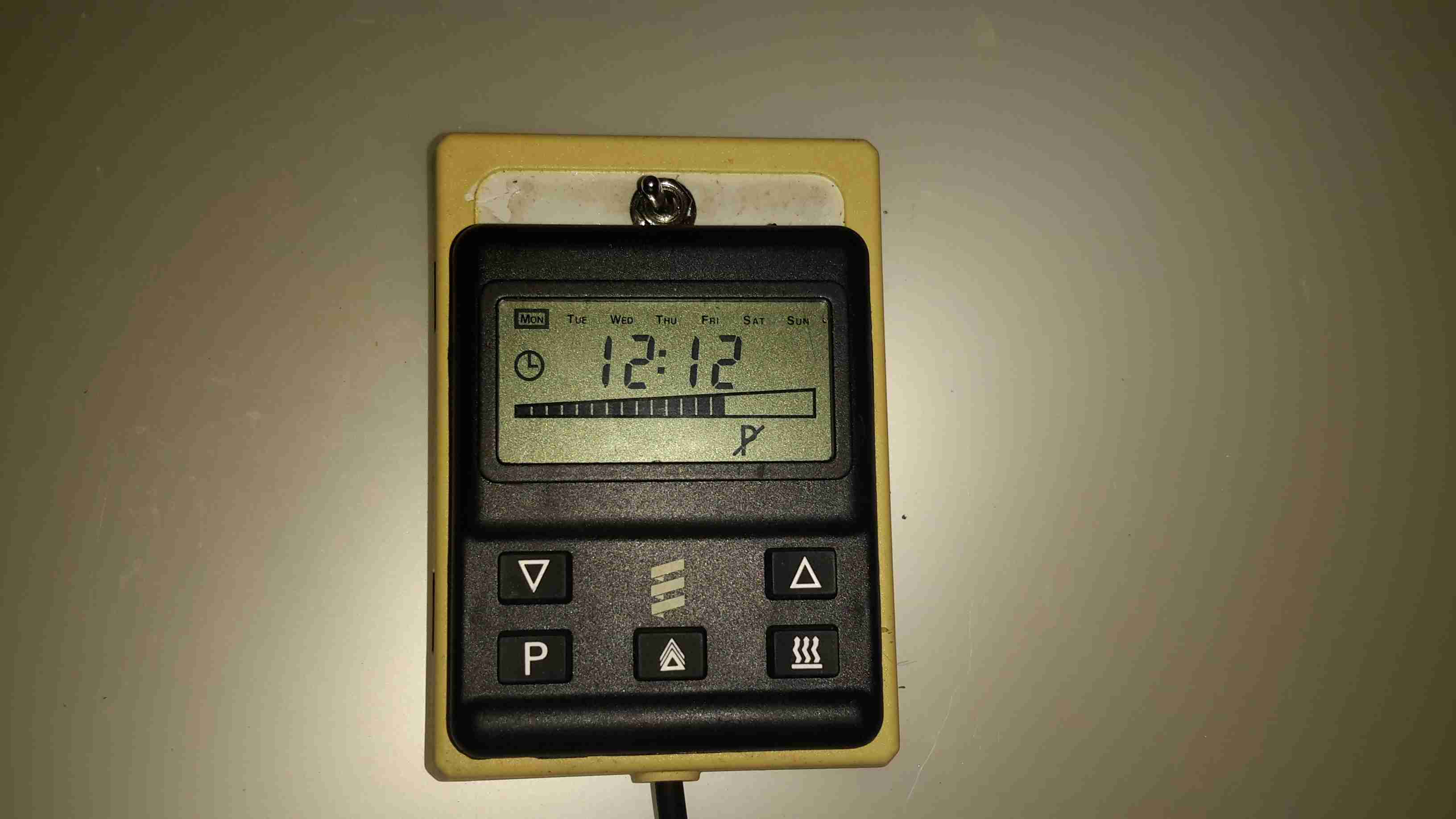
The Eberspacher heaters can be controlled with a single switch, but it’s more convenient to have some temperature control & the option of a timer. Above is an ex-BT 701 series controller, with built in 7-day programmer. Being an ex-BT van version though, it’ll only switch the heater on for 1 hour at a time.
To get around this slight niggle, I fitted a bypass toggle switch.
Remote Control
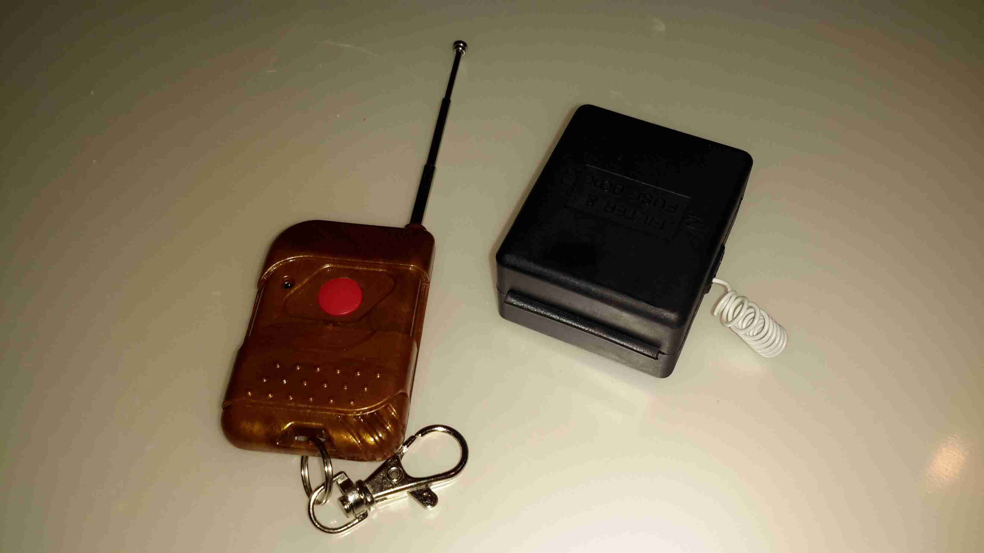
For a bit of extra convenience, I got an RF remote controlled relay module from eBay (£5).
This allows me to switch things on remotely, so I can return to a nice toasty tent while camping.
There is an official RF remote for Eberspacher heaters, but I’ve no doubt they’re hideously expensive.
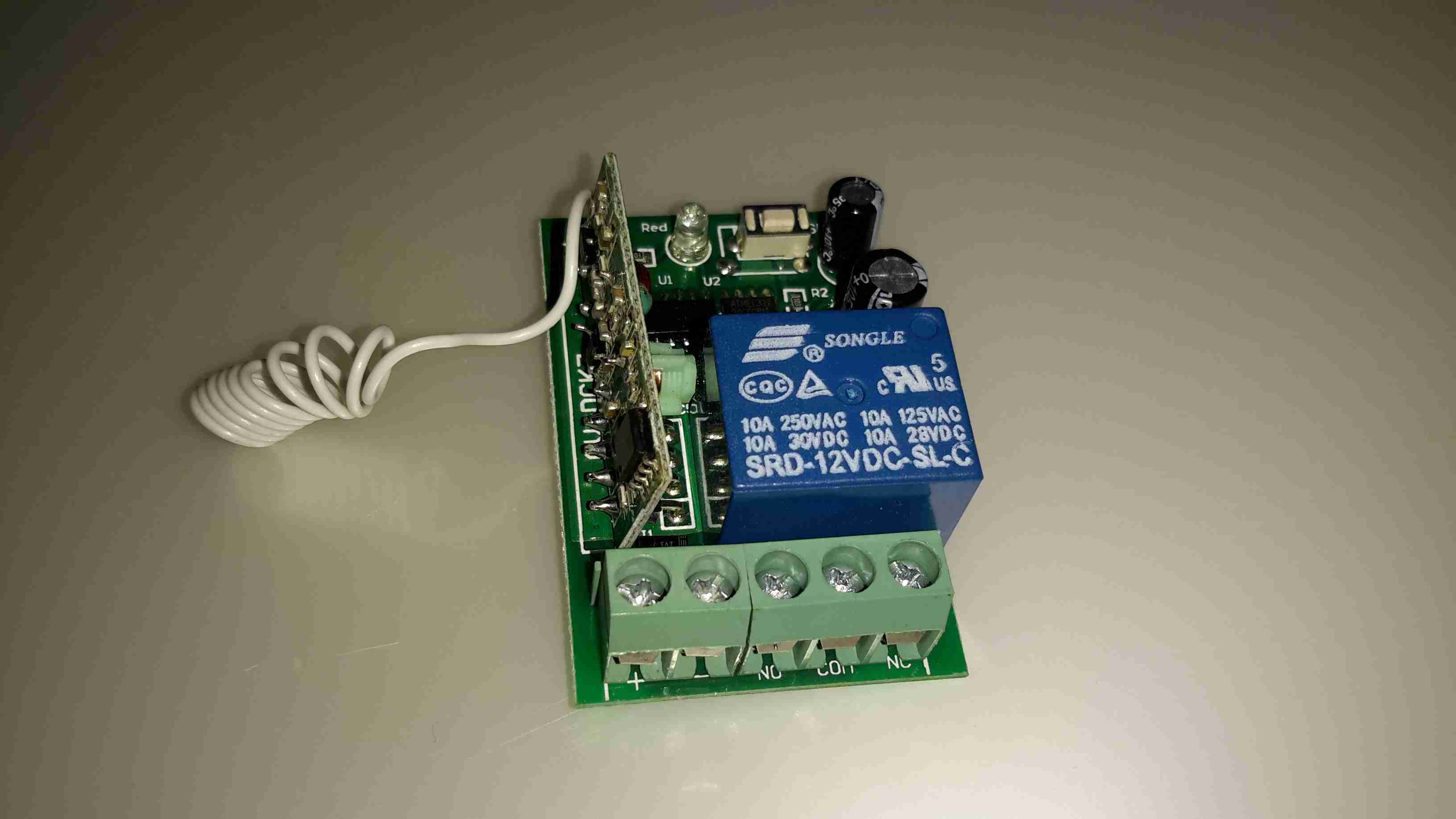
RF Receiver
Here’s the receiver PCB, there’s an EEPROM & a microcontroller onboard for handling the codes the remotes send, but as the number has been scrubbed off the micro, no data there. This uses a standard RF receiver module.
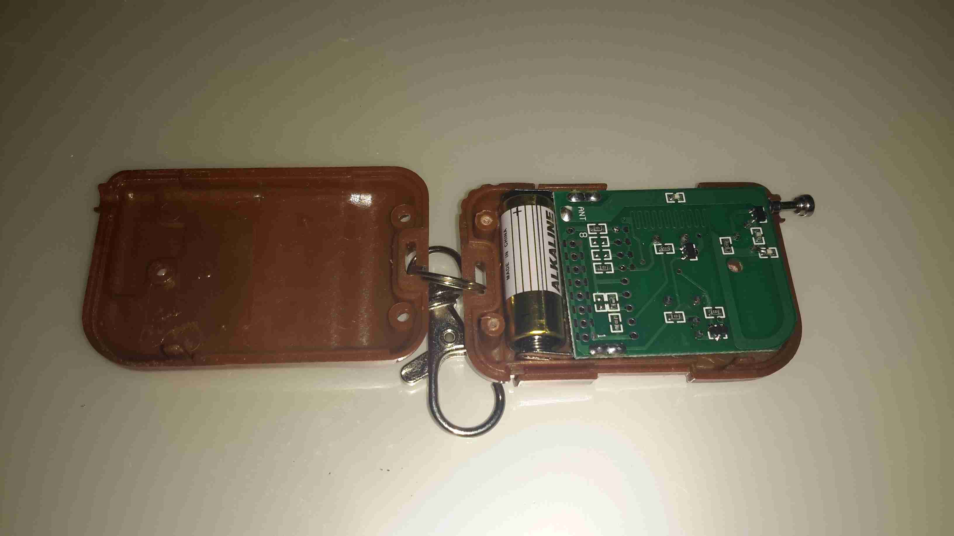
RF Remote
Here’s the remote itself, this uses a 12v battery instead of a 3v lithium cell. A little of a pain since these batteries can be a bit pricey.
As this RF system operates on 315MHz, it’s technically illegal in the UK, but I was unable to find a 433MHz version with the features required. Nevermind ;).
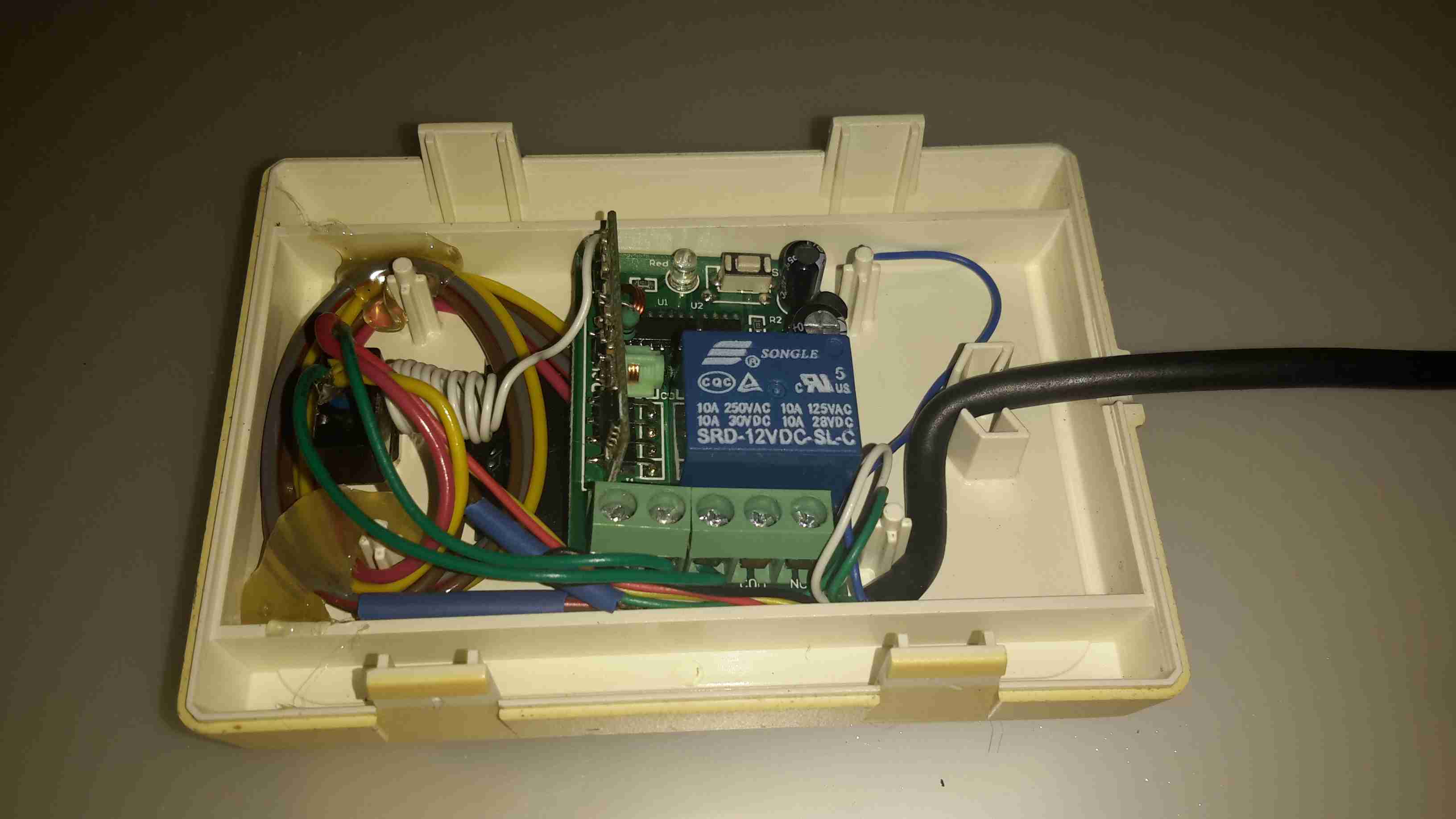
Controller Internals
Here’s the module installed in the controller casing. I have since run the antenna wire around the edge of the case to try & get the furthest range on receive. The relay contacts are just paralleled across the bypass switch, so when the relay energizes the heater fires up.
Luckily the thermostatic control portion of the 701 programmer is operational even when heating mode is not active.
I’m no fan of power inverters. In my experience they’re horrifically inefficient, have power appetites that make engine starter motors look like electric toothbrushes & reduce the life expectancy of lead-acid batteries to no more than a few days.
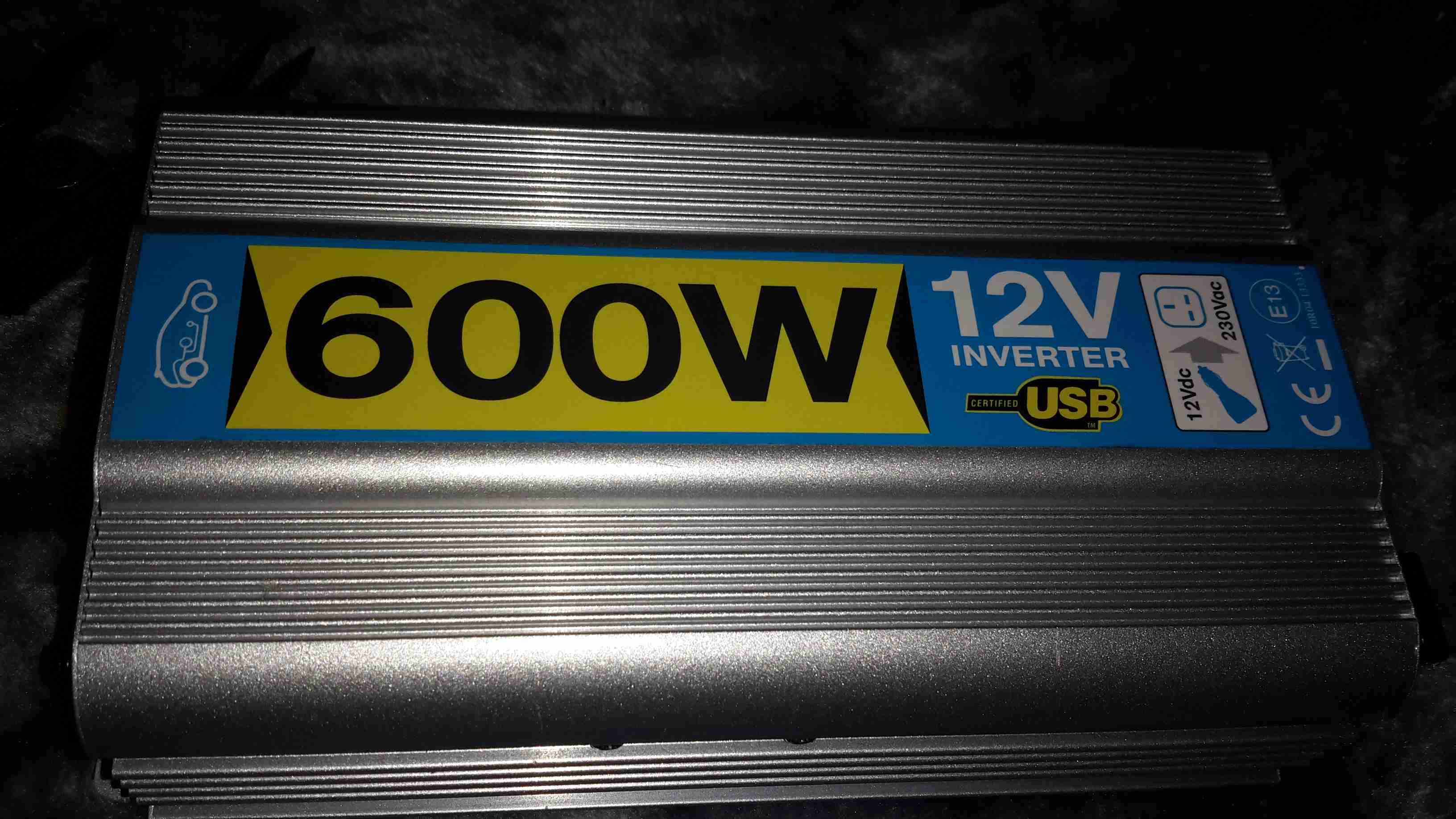
However I have decided to do a little analysis on a cheapo “600W” model that Maplin Electronics sells.
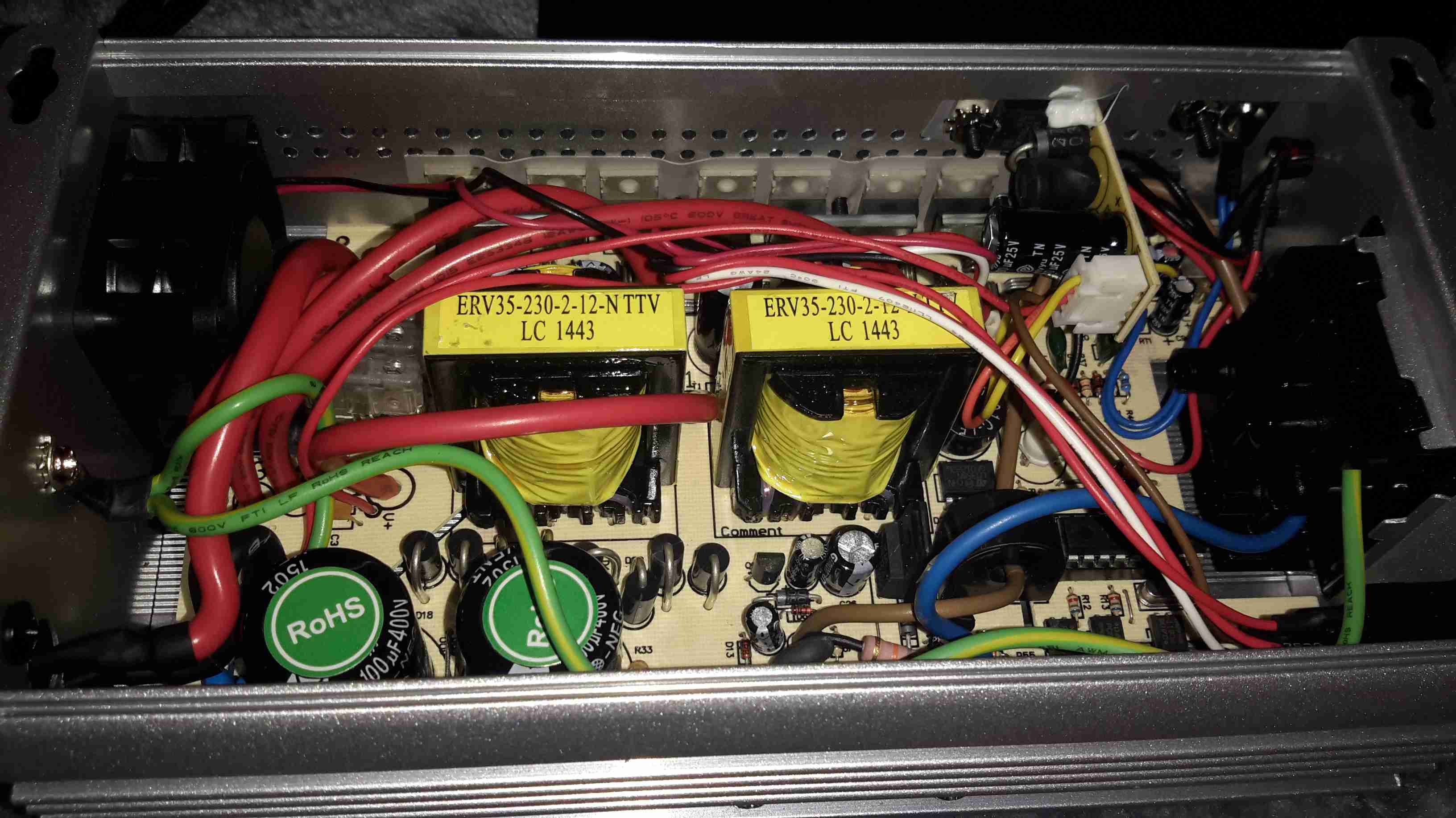
Cover Removed
After a serious amount of metallic abuse, the bottom cover eventually came off. The sheet of steel used to close the bottom of the aluminium extrusion was wedged into place with what was probably a 10 ton hydraulic press.
As can be seen from the PCB, there’s no massive 50Hz power transformer, but a pair of high frequency switching transformers. Obviously this is to lighten the weight & the cost of the magnetics, but it does nothing for the quality of the AC output waveform.
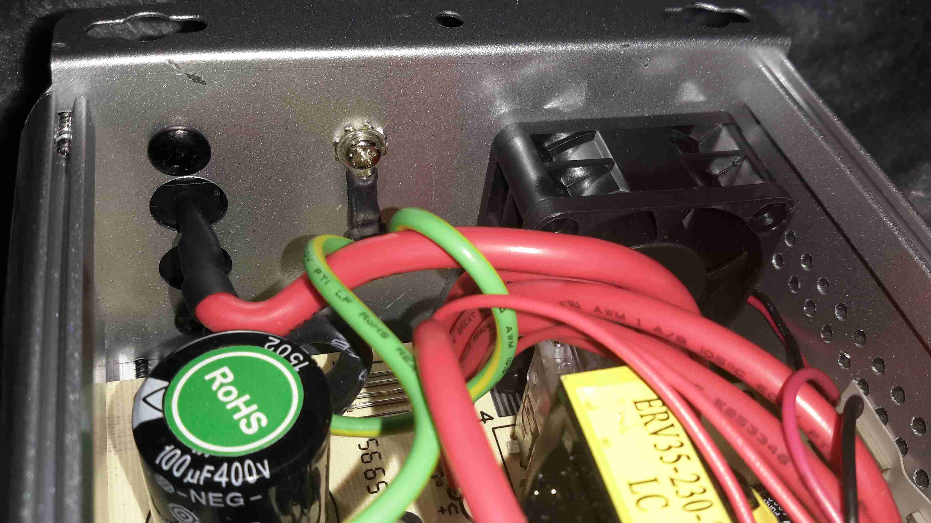
DC Input End
The 12v DC from the battery comes in on very heavy 8-gauge cables, this device is fused at 75A!
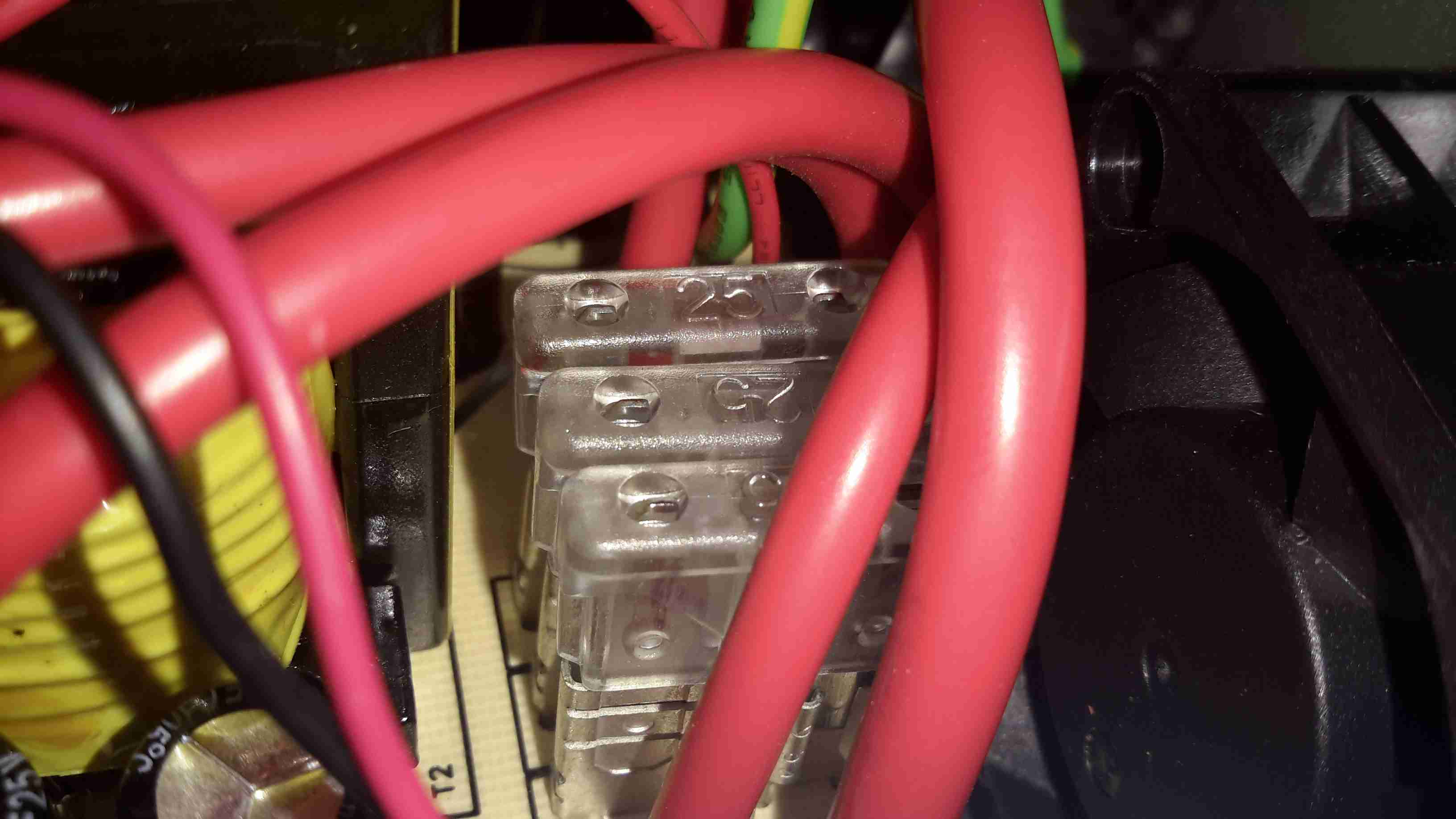
DC Fuses
Here’s the fusing arrangement on the DC input stage, just 3 standard blade-type automotive fuses. Interestingly, these are very difficult to get at without a large hammer & some swearing, so I imagine if the user manages to blow these Maplin just expect the device to be thrown out.
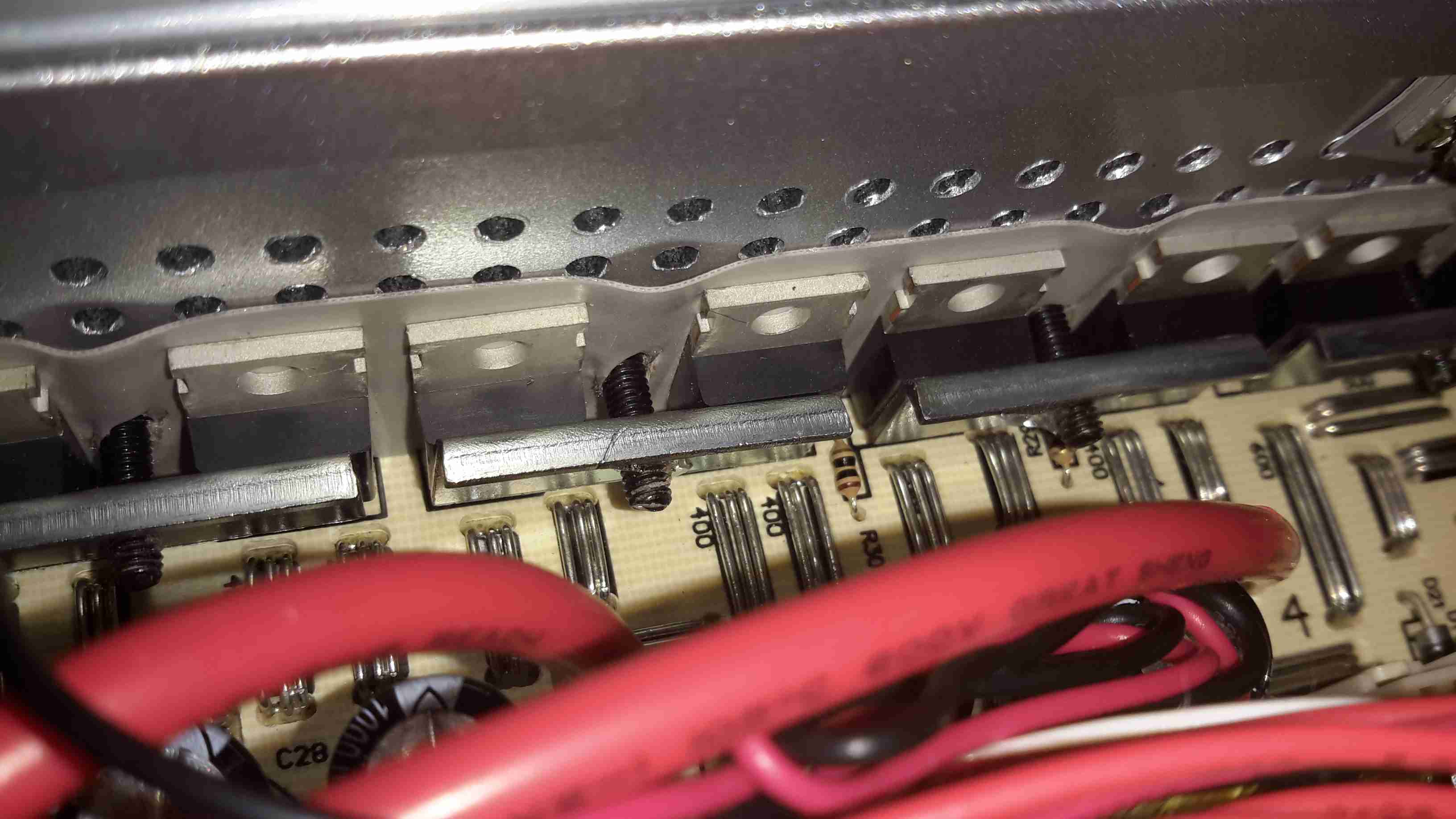
Input DC-DC Switching MOSFETs
On the input side, the DC is switched into the pair of transformers to create a bipolar high voltage DC supply.
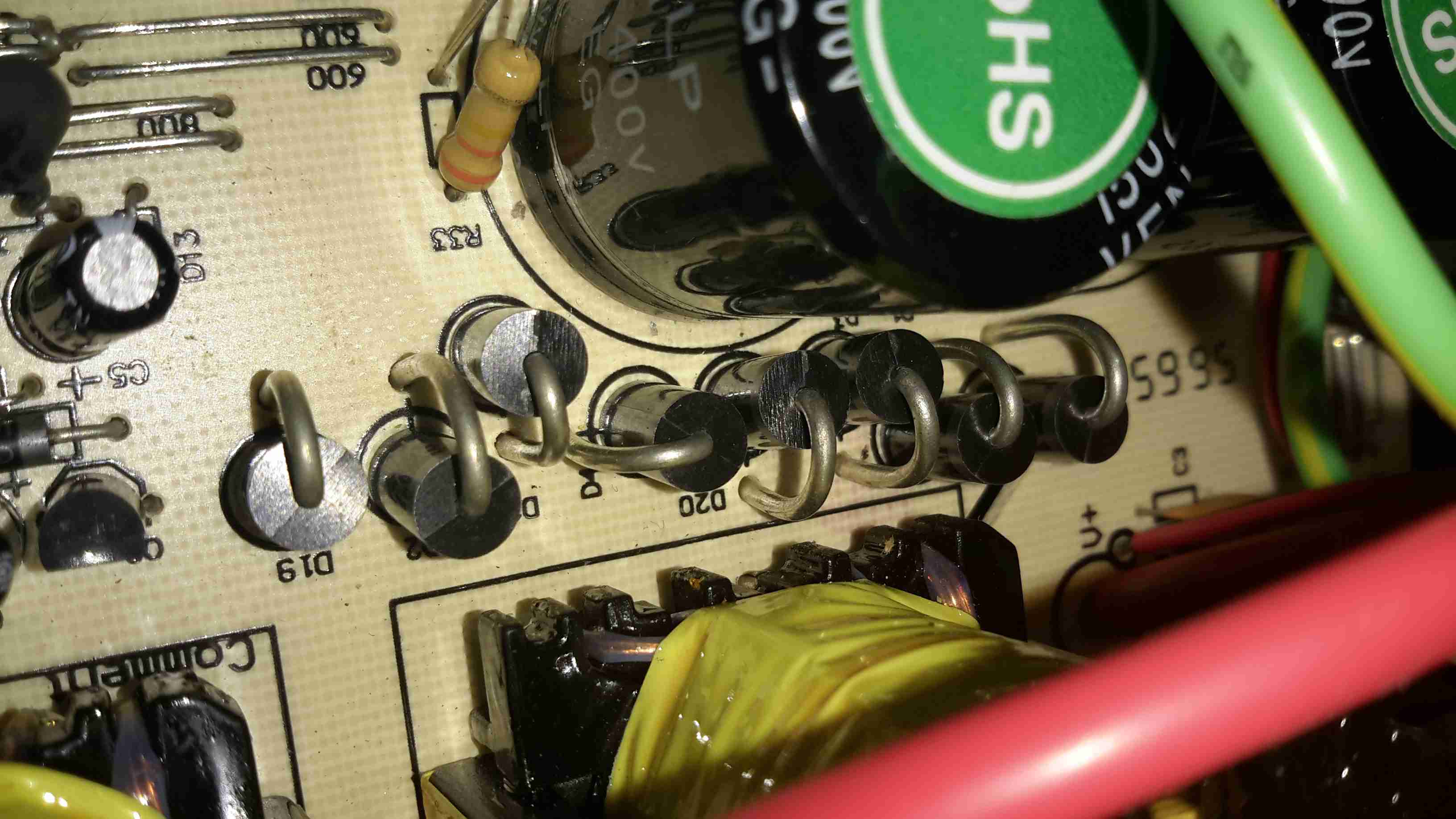
High Voltage Rectifiers
The large rectifier diodes on the outputs of the transformers feed into the 400v 100µF smoothing capacitors.
As mains AC is obviously a bipolar waveform, I’m guessing this is generating a ±150v DC supply.
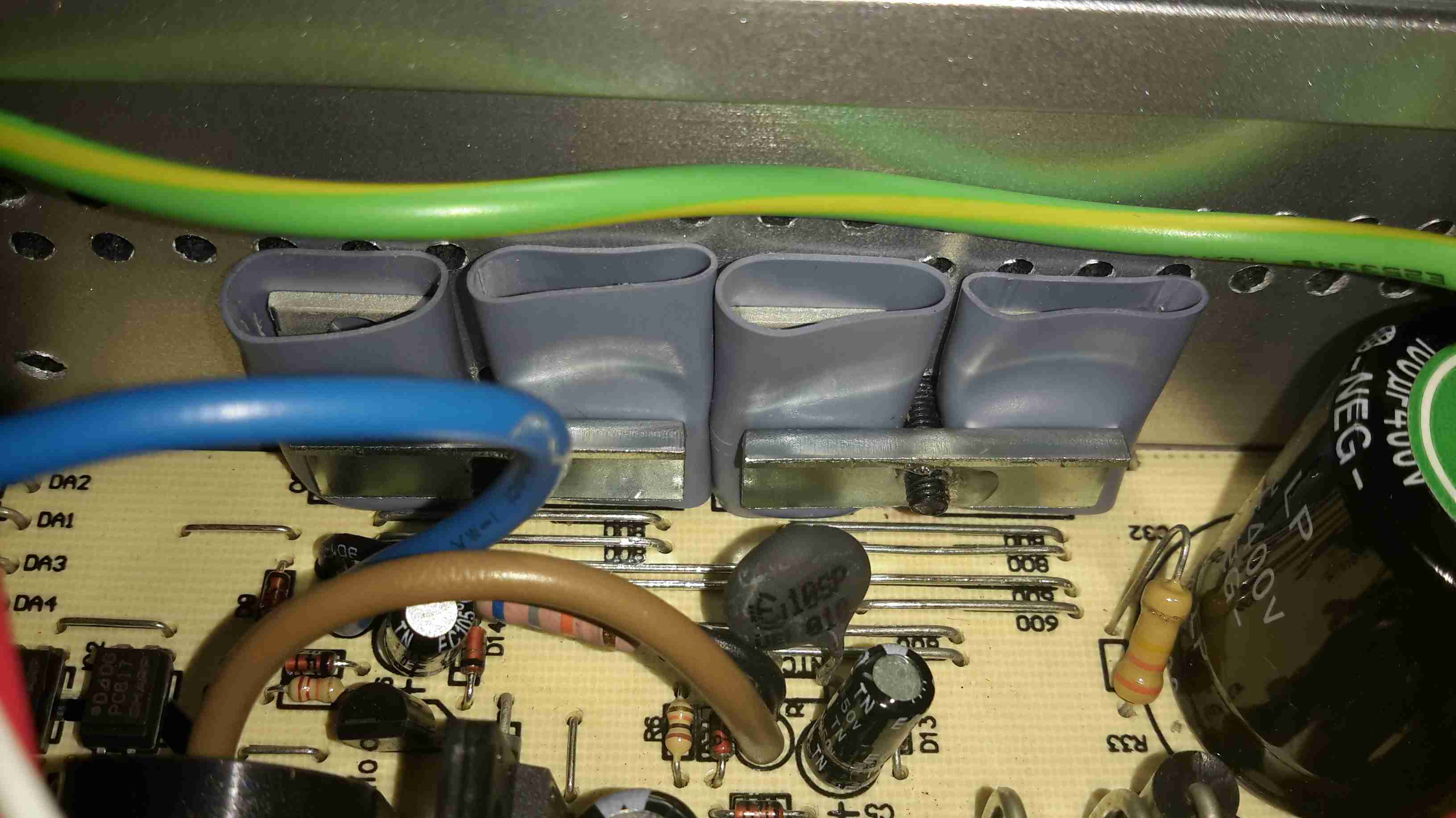
Output MOSFETs
After the high voltage is rectified & smoothed, it’s switched through 4 more MOSFETs on the other side of the PCB to create the main AC output.
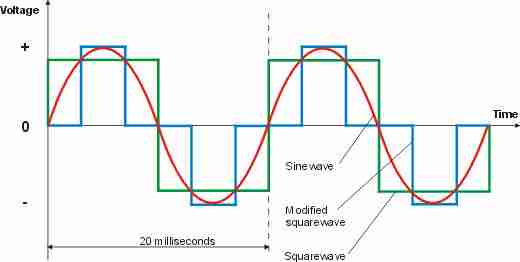
The label states this is a modified-sine output, so I’d expect something on the scope that looks like this:
Inverter Waveforms
Modified-sine doesn’t look as bad as just a pure square output, but I suspect it’s a little hard on inductive loads & rectifiers.
However, after connecting the scope, here’s the actual waveform:
Actual Waveform
It’s horrific. It’s not even symmetrical. There isn’t even a true “neutral” either. The same waveform (in antiphase) is on the other mains socket terminal. This gives an RMS output voltage of 284v. Needless to say I didn’t try it under load, as I don’t possess anything I don’t mind destroying. (This is when incandescent lamps are *really* useful. Bloody EU ;)).
About the only thing that it’s accurate at reproducing is the 50Hz output, which it does pretty damn well.
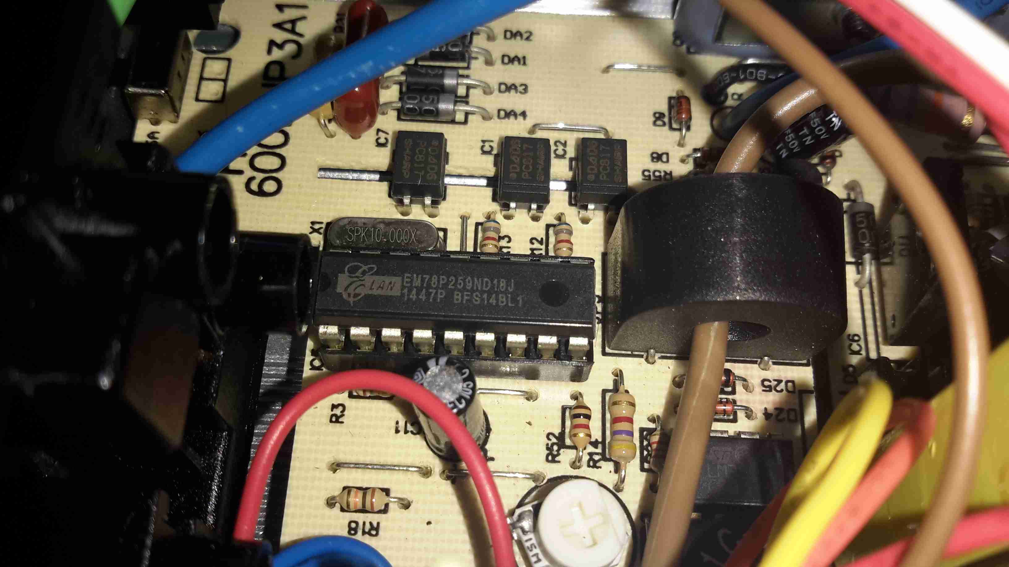
System Microcontroller
As is usual these days, the whole system is controlled via a microcontroller.
I go camping on a regular basis here in the UK, and often even in summer it’s horribly cold at night in a field somewhere in the middle of Leicestershire. This doesn’t go too well with my severe aversion to being cold.
For the past several years I’ve used a Tilley lamp for some heat & light while at festivals & general camping, but it’s heat output is less than stellar when used in a 6-man tent.
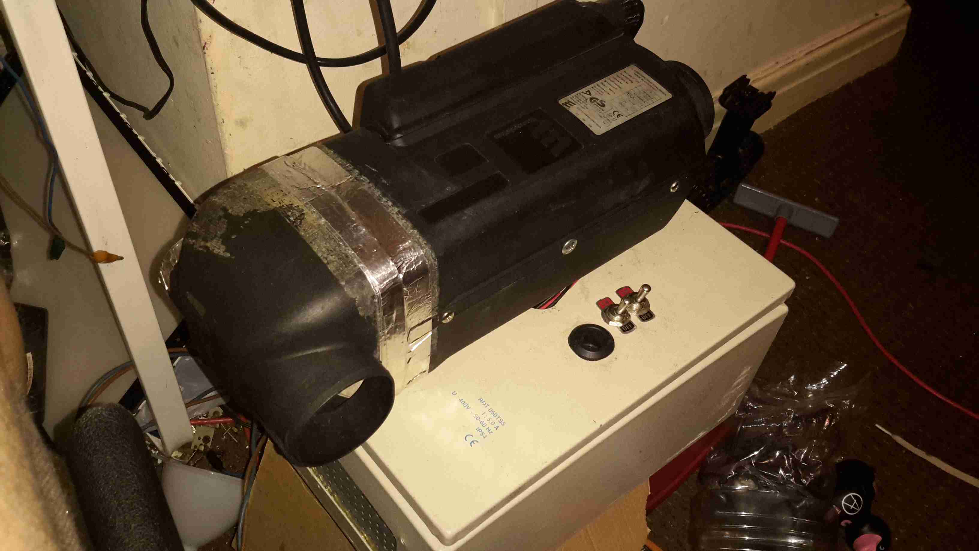
An Eberspacher diesel heater was what was required for the job. Above is the unit as it’s built at the moment – I’ve used an old D1LCC 1.8kW heater that was recently decommissioned from nb Tanya Louise, as it’s getting a bit funny about what kind of fuel it’ll run on in it’s old age. It’ll work perfectly well on kerosene though – a fuel I already take with me camping for the Tilley.
It’s mounted on a base box, which is a repurposed steel electrical junction box that saw a previous life containing a 3-phase fan motor controller.
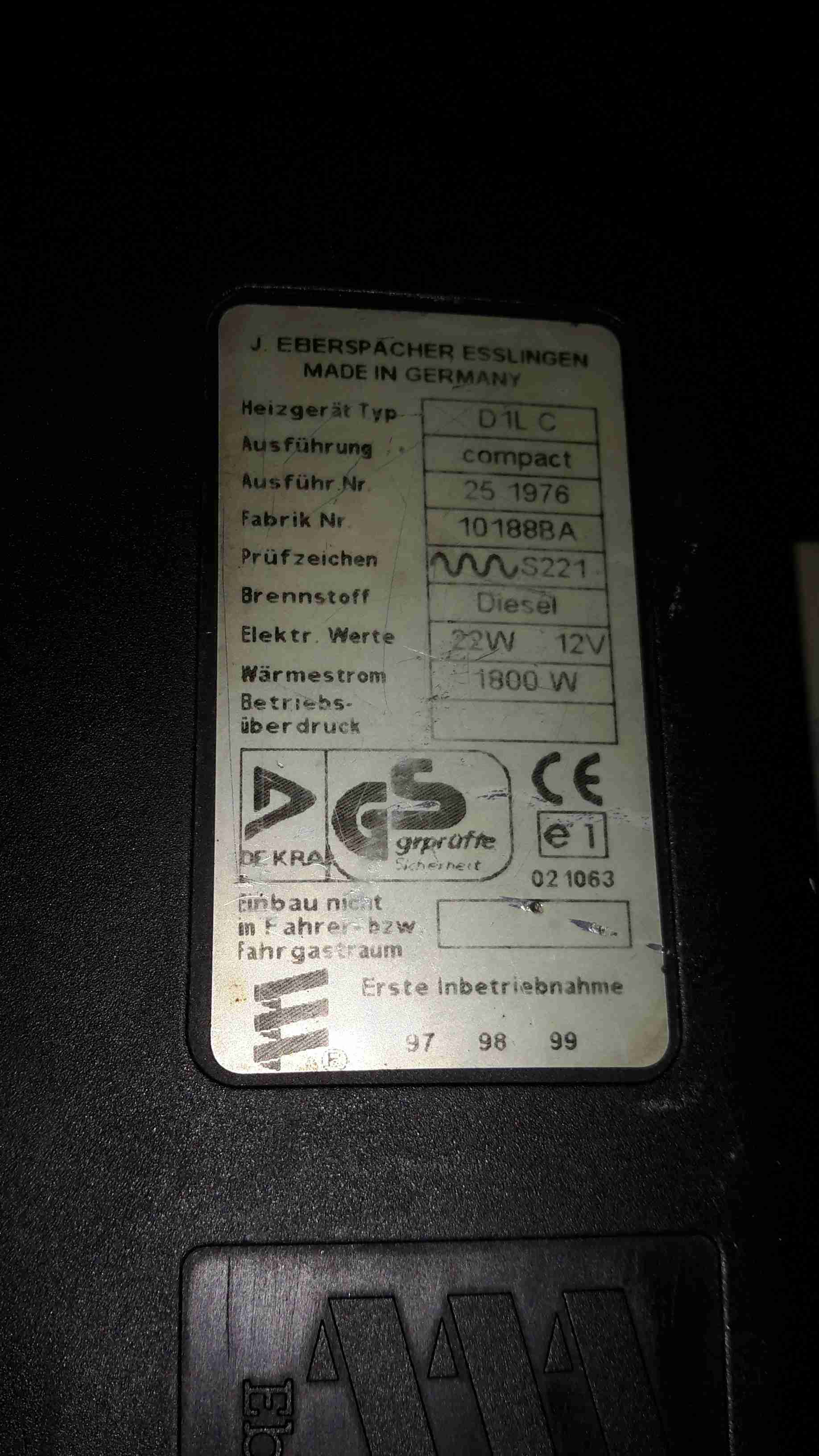
Data Plate
Here’s the info on the heater unit itself. Drawing 22W of power at 12v I’ll be getting 1.8kW of heat output – sounds good to me.
Box Internals
Here’s a view into the base box before the circulation fans were fitted, in early prototype stage. I used a small toroid as a clunk on the end of the rubber fuel line 😉
Support Components
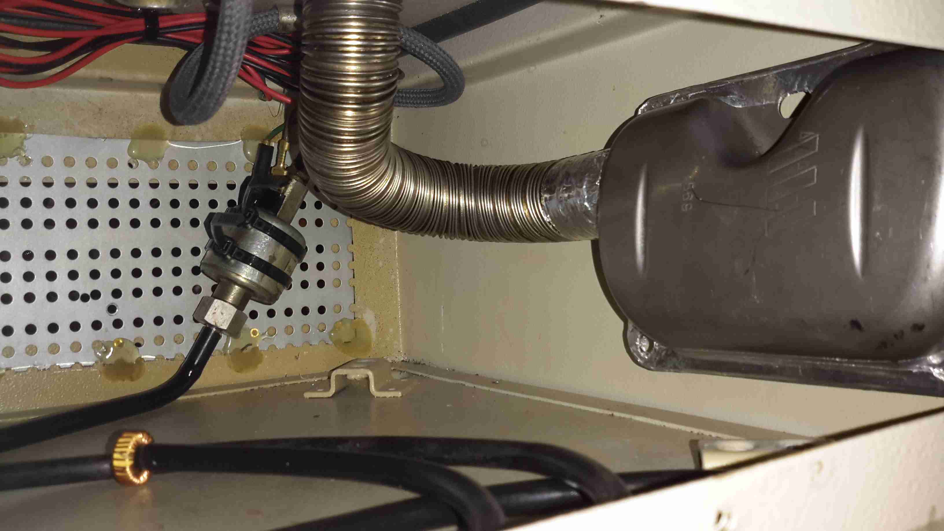
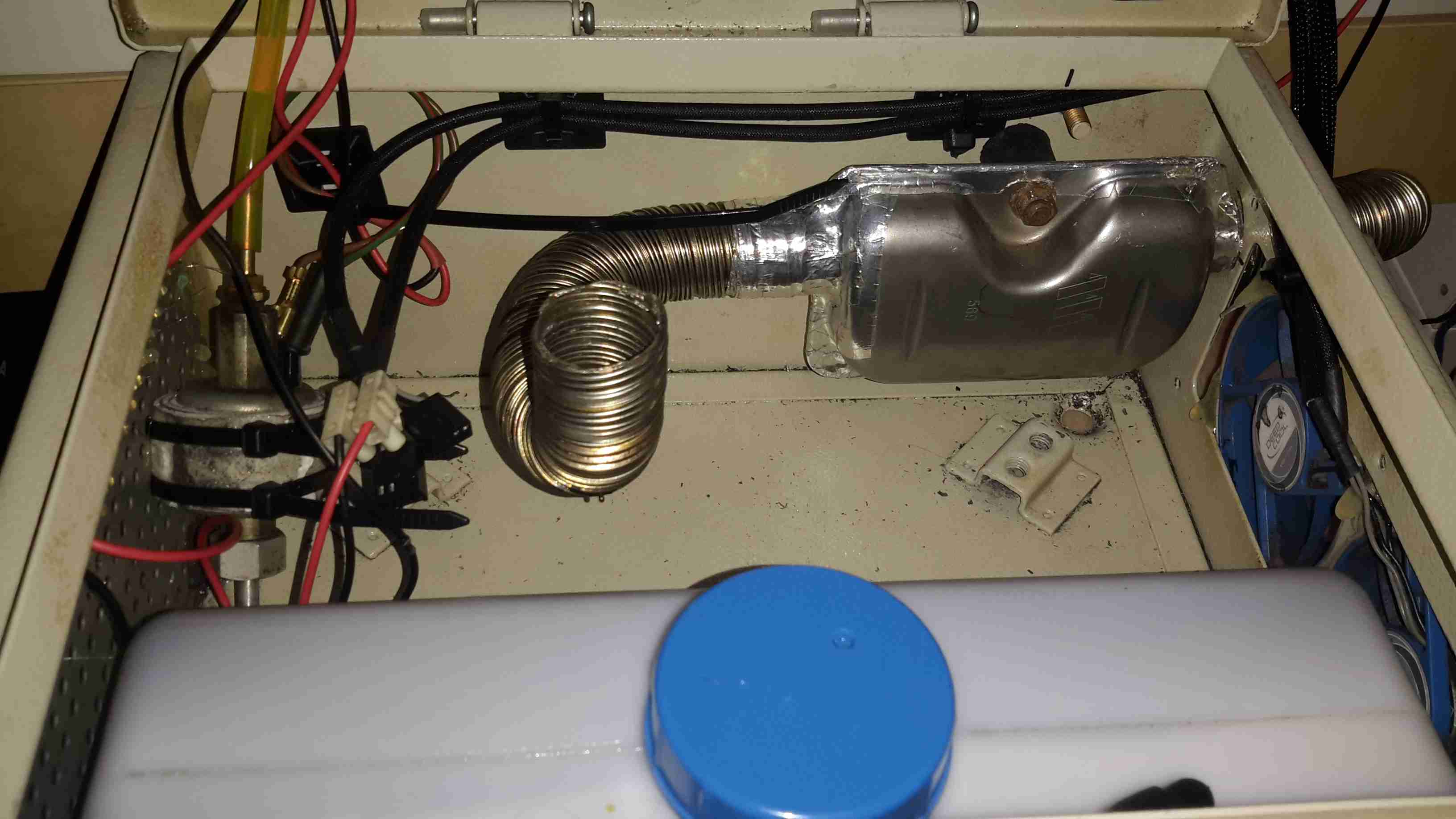
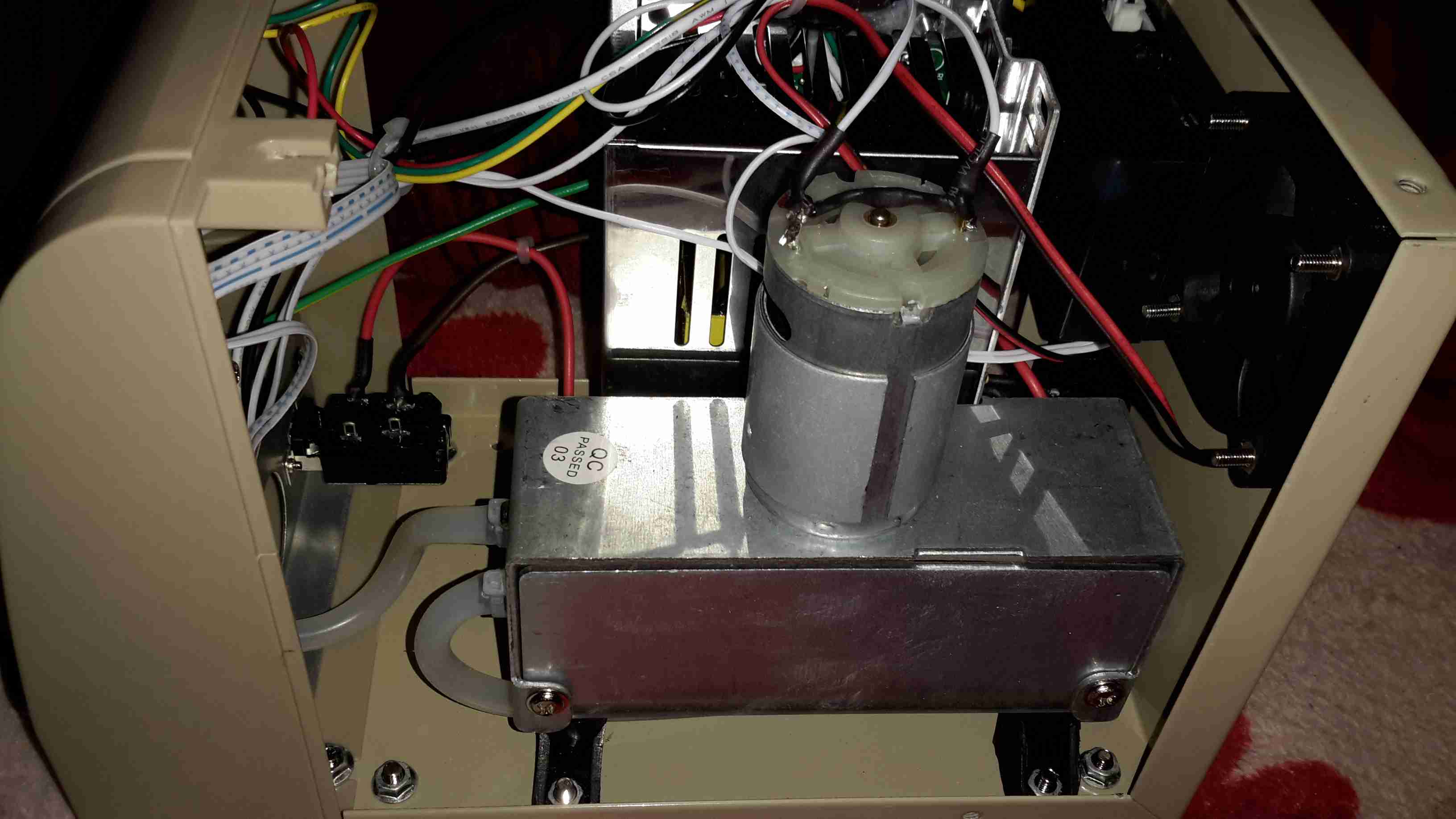
After a few bits from the Great eBay arrived, here’s the internals of the base unit at present. The fuel tank is a repurposed 2L fridge water container – made of tough HDPE so it’s fuel resistant.
The fuel pump is mounted on the left side next to the tank – having been wrapped in some foam to deaden the continual ticking noise it creates. The exhaust & it’s silencer are mounted at the rear, the silencer being retained by a surplus rubber shock mount. Luckily the exhaust systems on these heaters don’t get particularly hot, so the rubber doesn’t melt.
The exhaust outlet is routed through the frame, to be attached to an external hose. I don’t want combustion gases in the tent with me!
Standard Eberspacher silencers also aren’t gas-tight from the factory – they’re designed to be used in the open on the underframe of a vehicle, so I’ve covered all the seams in aluminium tape to make the system airtight.
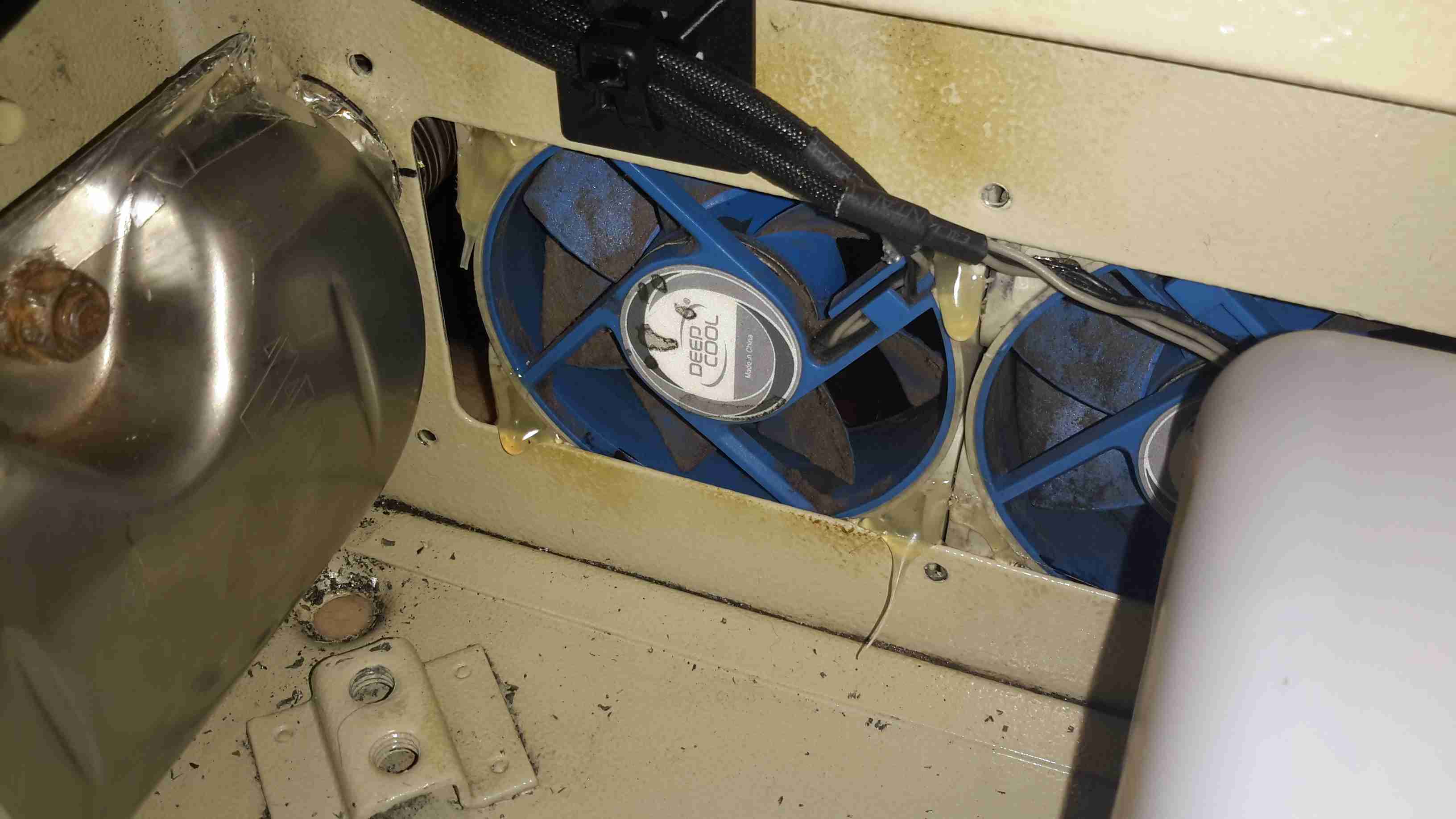
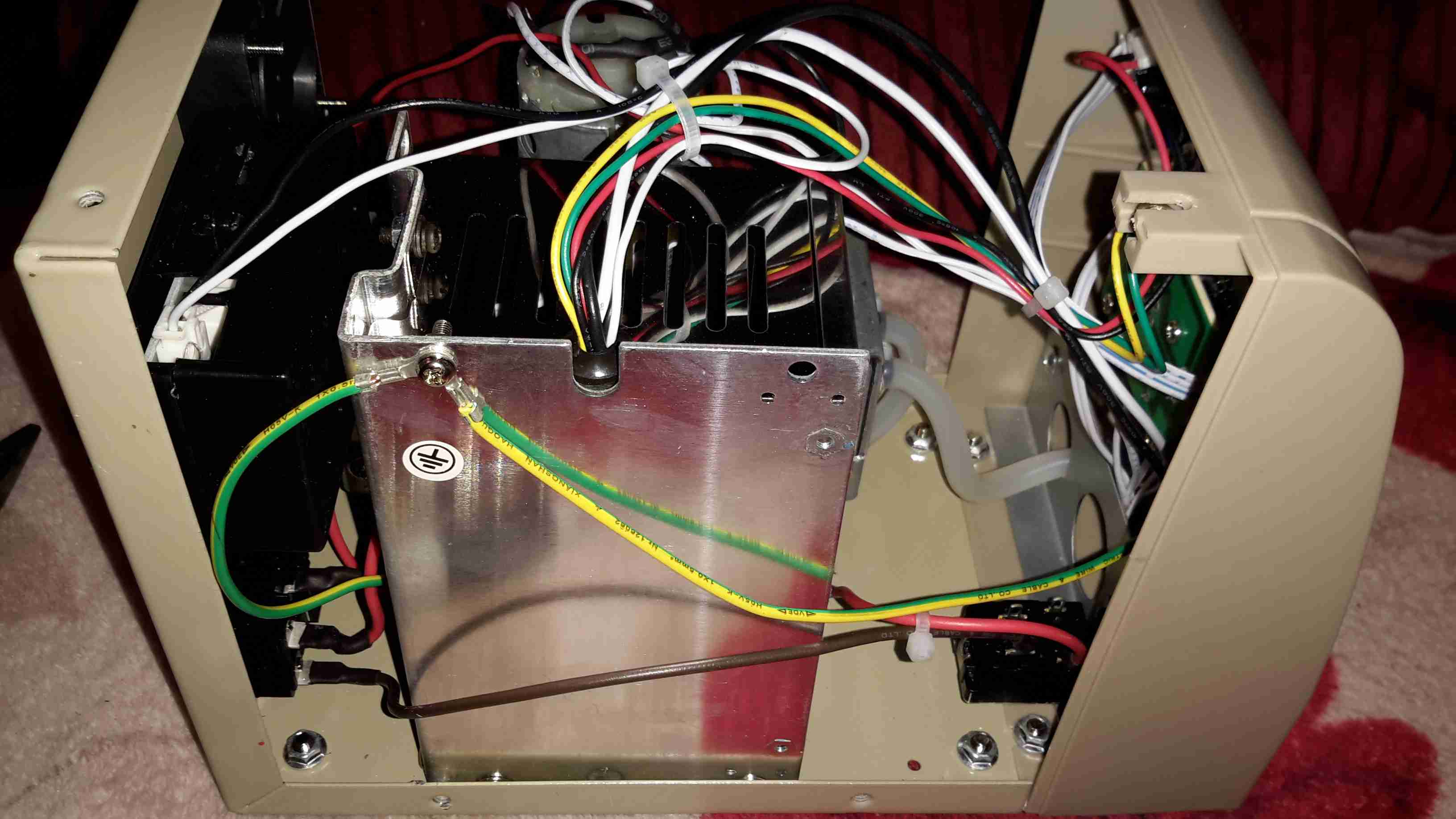
Ventilation
To make sure that the support components don’t get overheated with the exhaust being in such close proximity, and to pull a little more heat out of the system, a pair of slow-running 80mm fans has been fitted to the end of the box. These blow enough air through to give a nice warm breeze from the vents on the other end of the base.
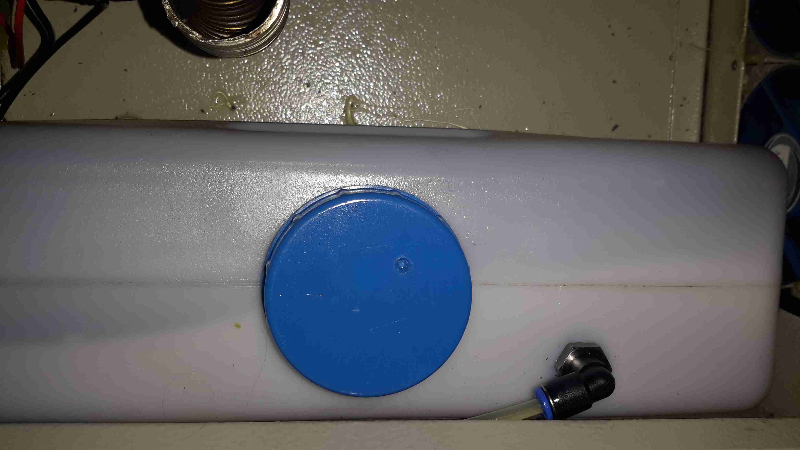
Fuel Tank
The tank I’ve used just so happened to be the perfect size to fit into the base box, and to tap the fuel off a bulkhead fitting was put into the top of the tank, with a dip tube on the other side. The fuel line itself is tiny – only 4mm.
If the specifications from Eberspacher are to be believed, 2L of fuel on board will allow the system to run for about 8 hours on full power, or 16 hours on minimum power.
Being inside the base, refuelling is a little awkward at the moment, the heater has to completely cool before the exhaust can be detached without receiving a burn, so I’ll be building in a fuel transfer system from an external jerry can later to automate the process – this will also help to avoid messy fuel spills.
More to come when the rest of the system is worked out!
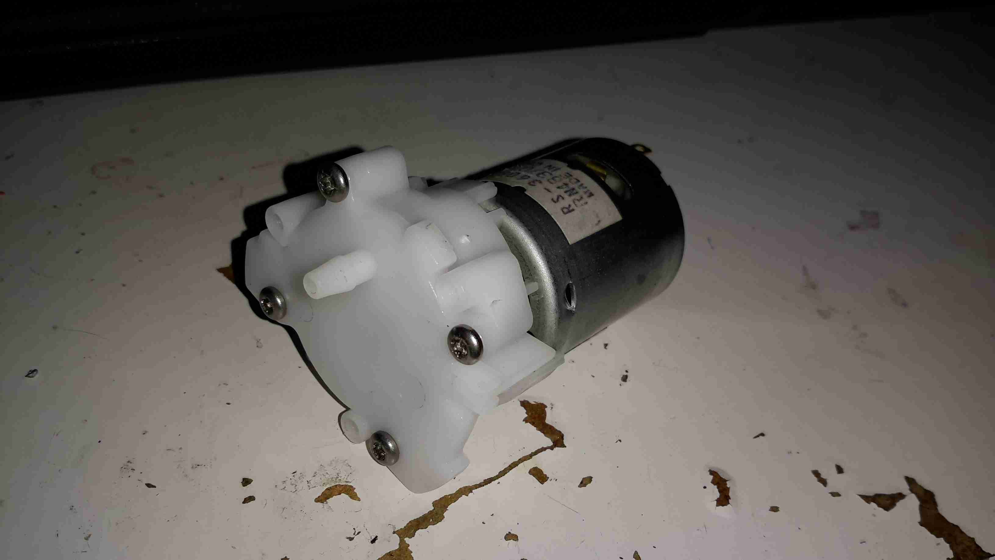
I got one of these to test since I’ve been in need of some small DC pumps for fluid transfer use. At £2 I can definitely afford to experiment.
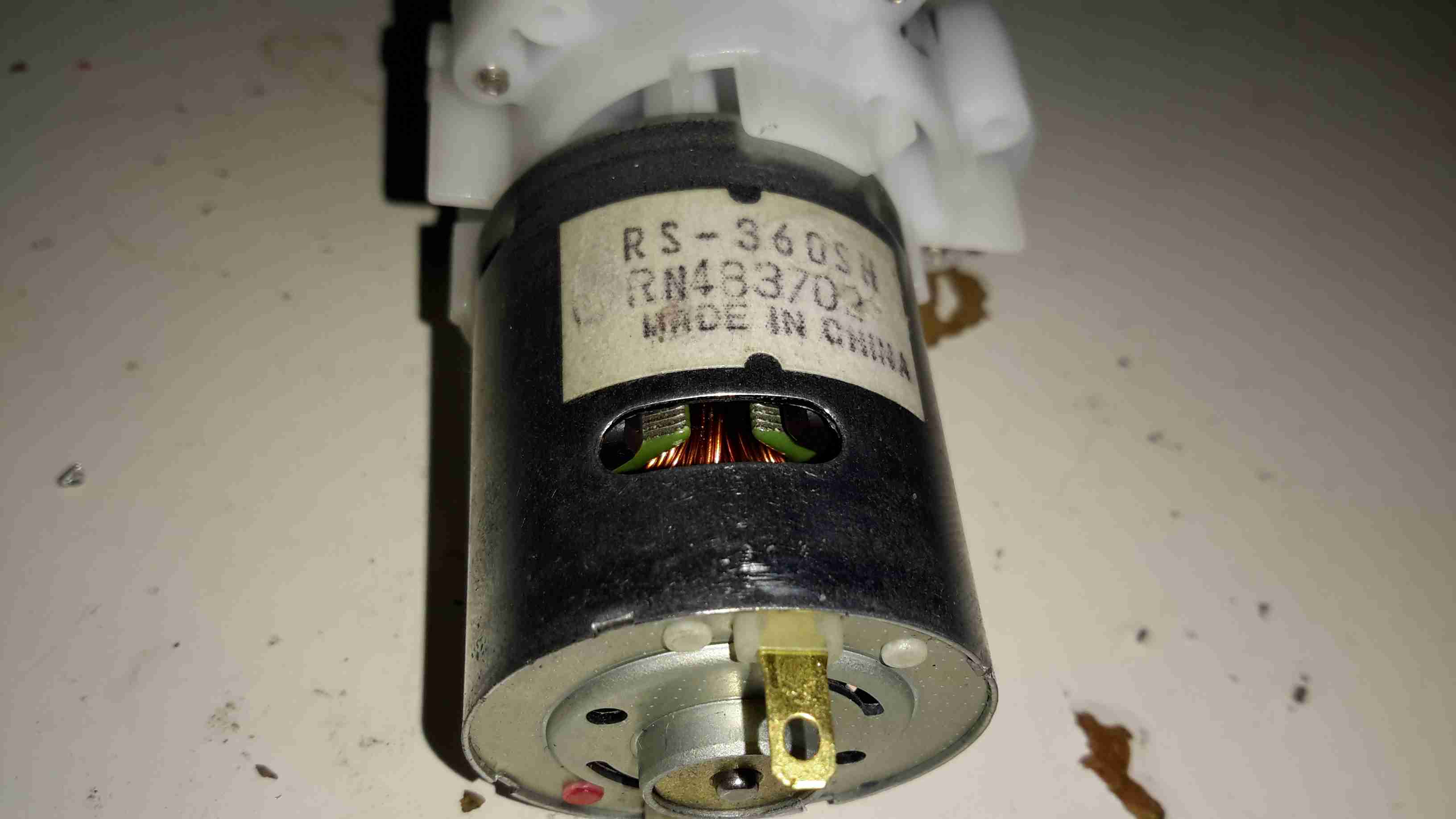
DC Motor
On the eBay listing, these pumps are rated at 3-12v DC, (I thought that was a bit wide of an operating range), I looked up the motor, an RS-360SH on Mabuchi’s website, they only have models in this range rated at 7.2v & 24v. Judging by the size of the windings on the armature & the fact that after a few minutes operation on 12v it gets rather hot, I’m going to say this is the 7.2v motor.
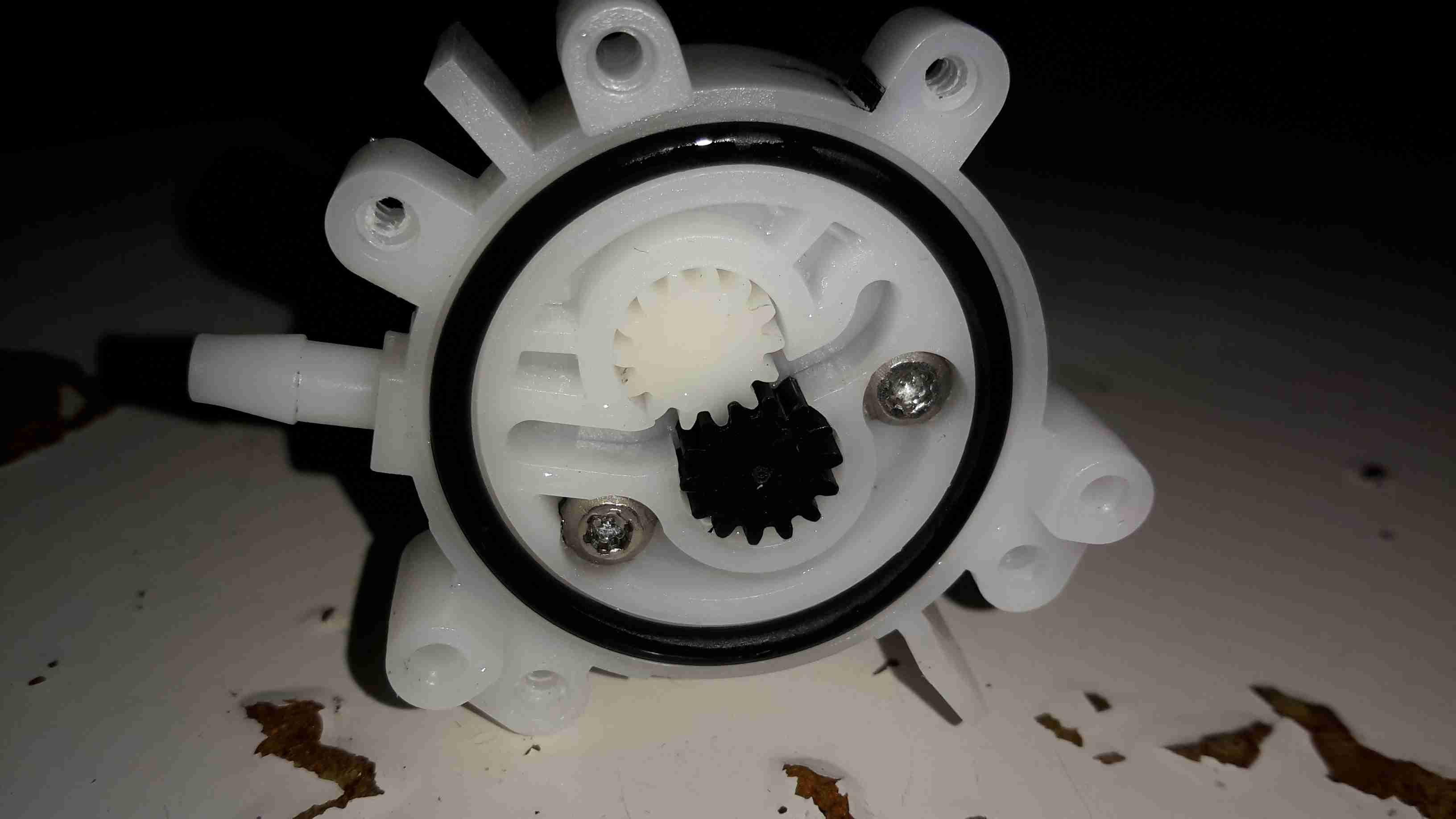
Pump Gears
Removing the screws releases the end cover & the pair of gears inside. This operates like any other hydraulic gear motor, albeit with much wider tolerances. It has no capability to hold pressure when the power is removed, and can be blown through easily.
Flow & pressure under power are quite good for the pump’s size, even though it’s noisy as hell.
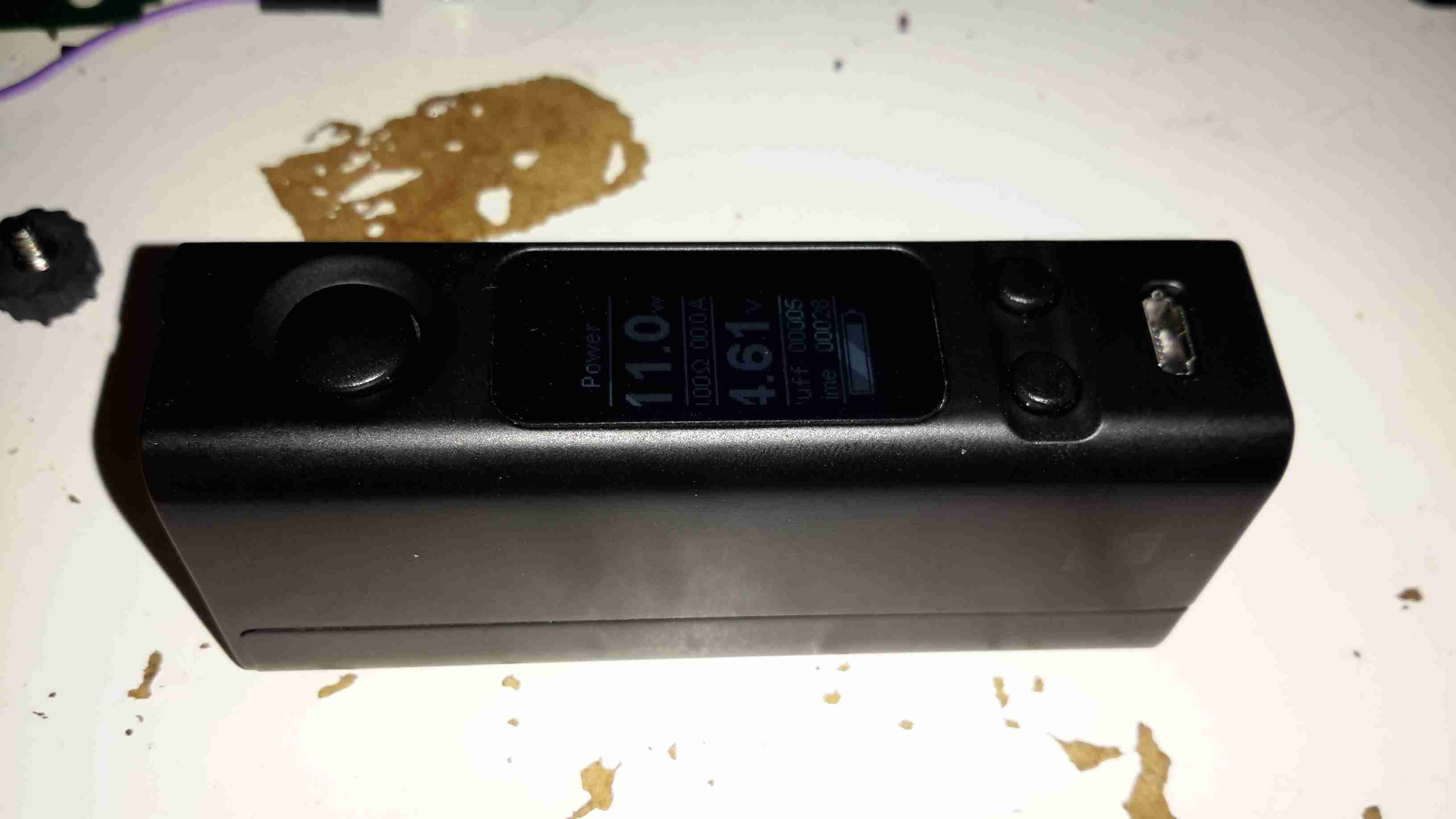
I’ve been a vaper now for many years, after giving up the evil weed that is tobacco. Here’s my latest acquisition in the vaping world, the JoyeTech eVIC 60W. This one is branded by Totally Wicked as the Forza VT60.
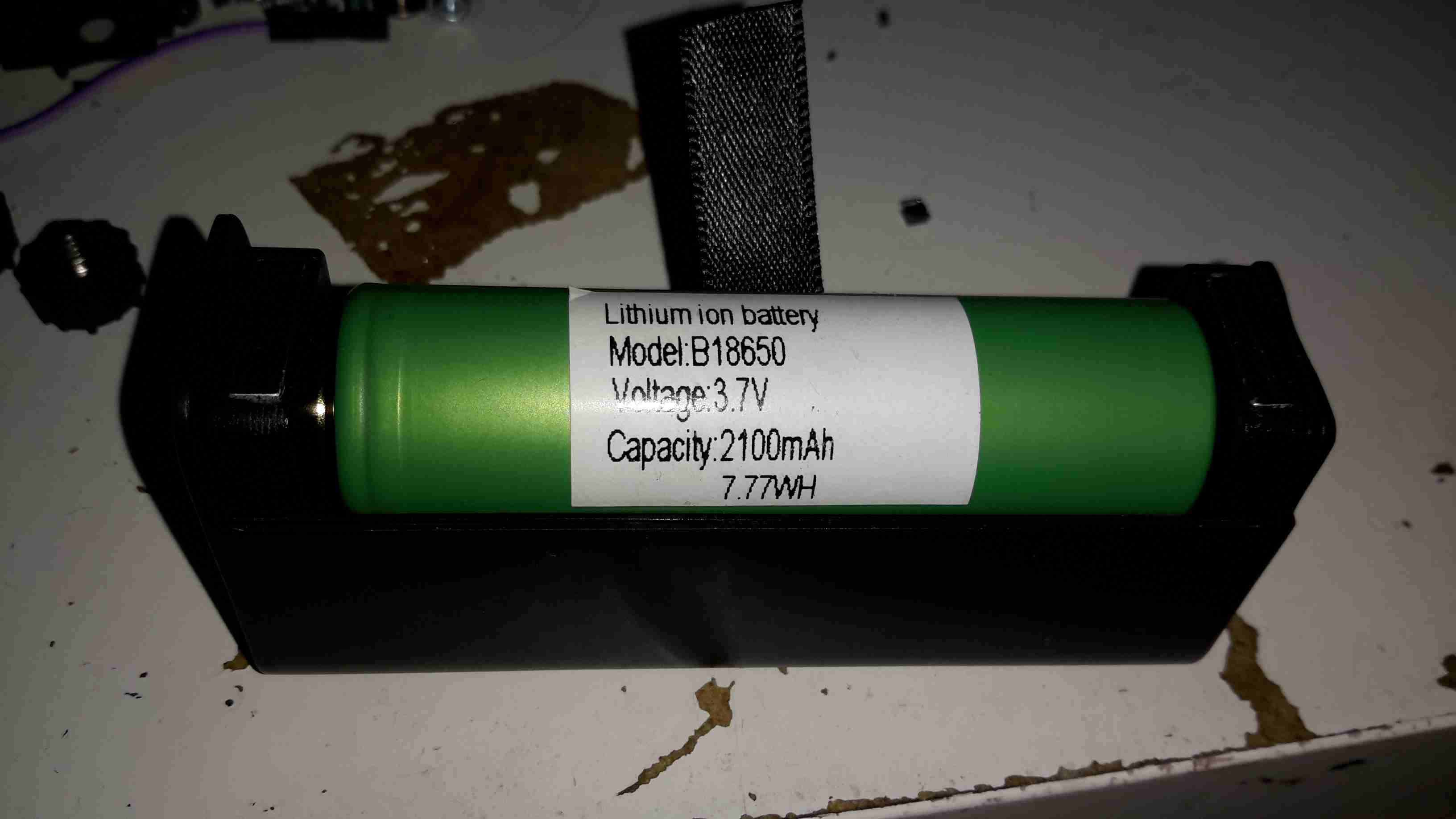
18650 Cell
Powered by a single 18650 Li-Ion cell, this one is a Sony VTC4 series, 2100mAh.
Under the battery a pair of screws hold the electronics in the main cast alloy casing.
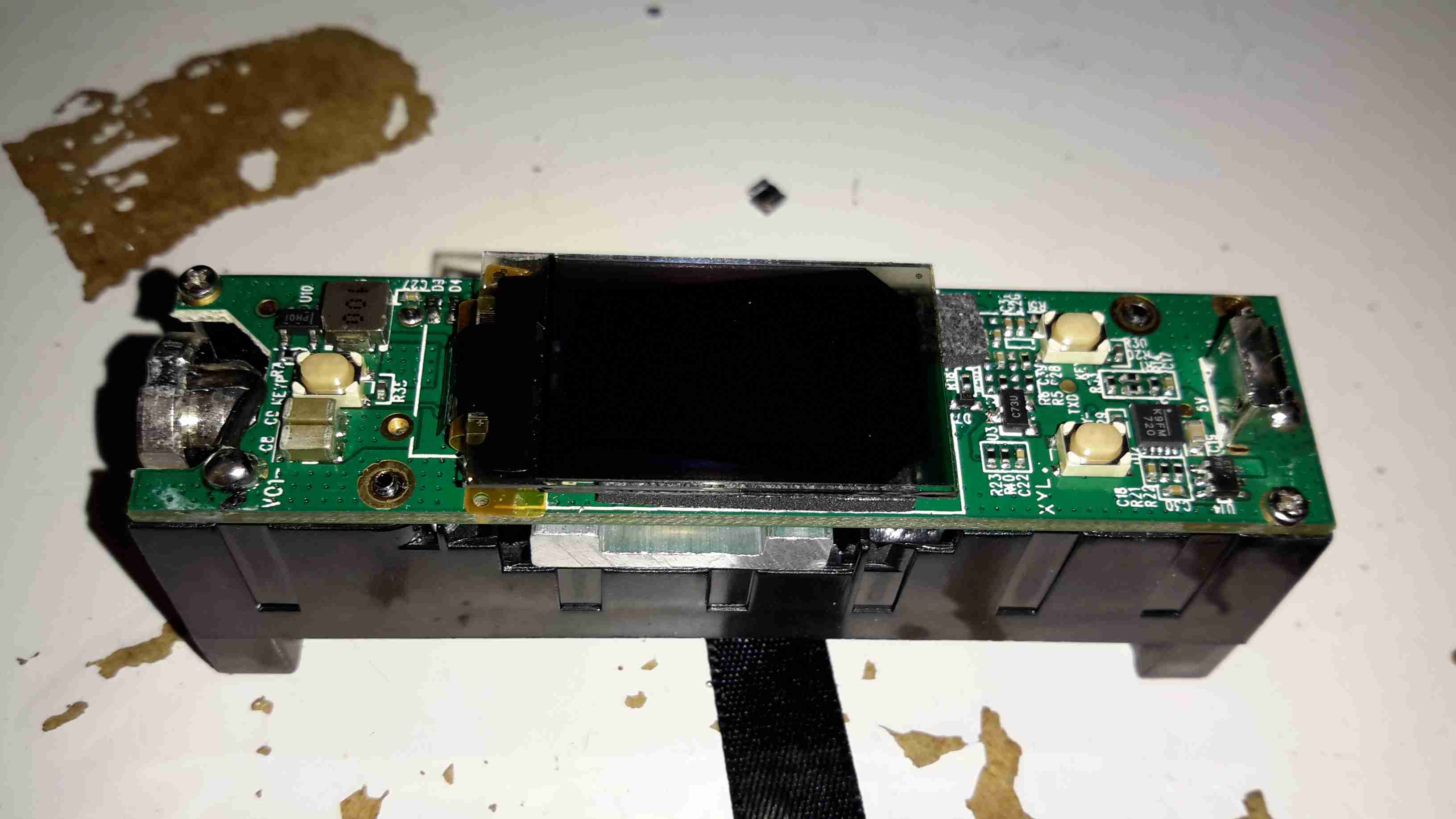
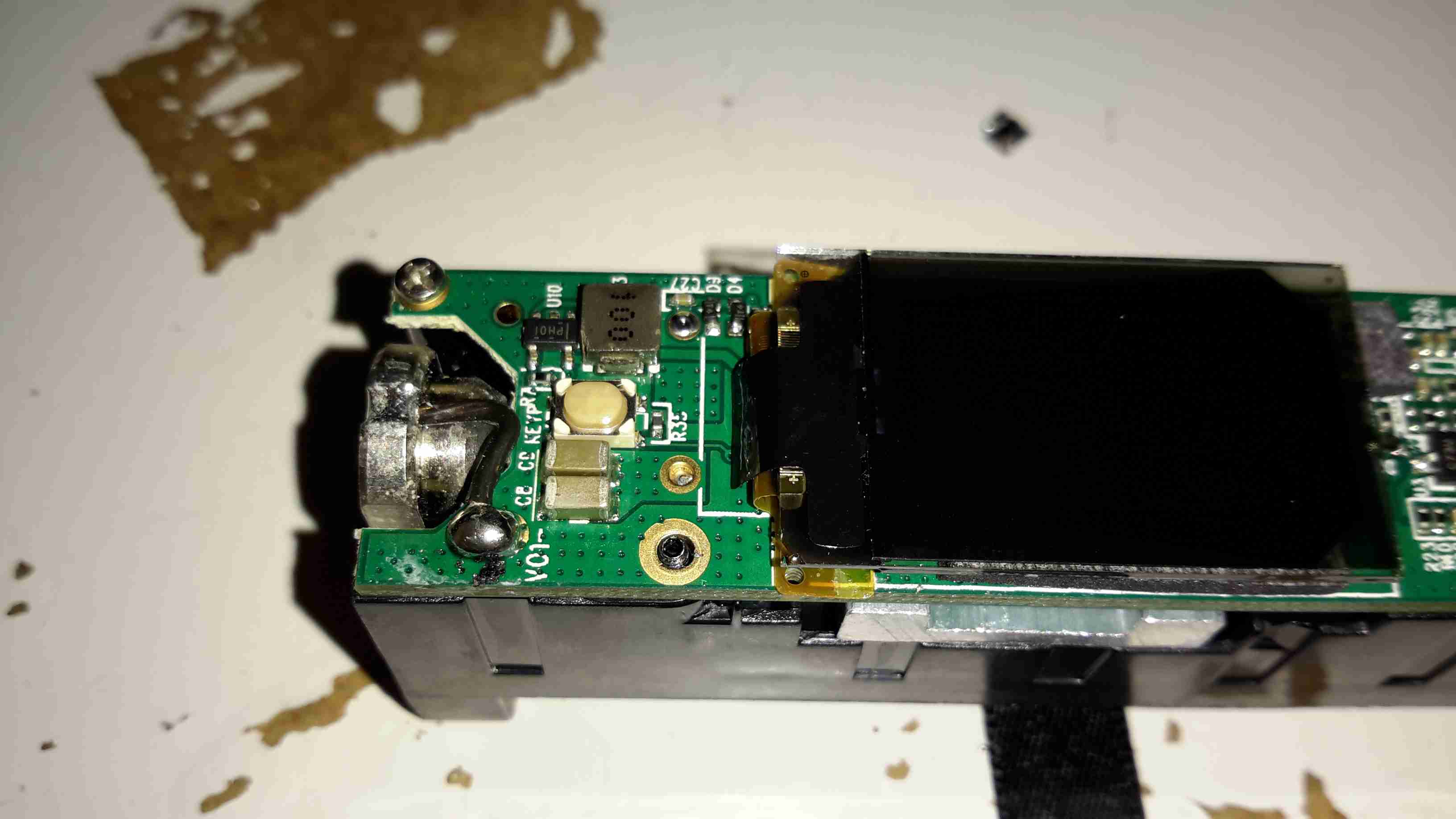
OLED Display
After removing the screws, the entire internal assembly comes out of the case, here’s the top of the PCB with the large OLED display in the centre.
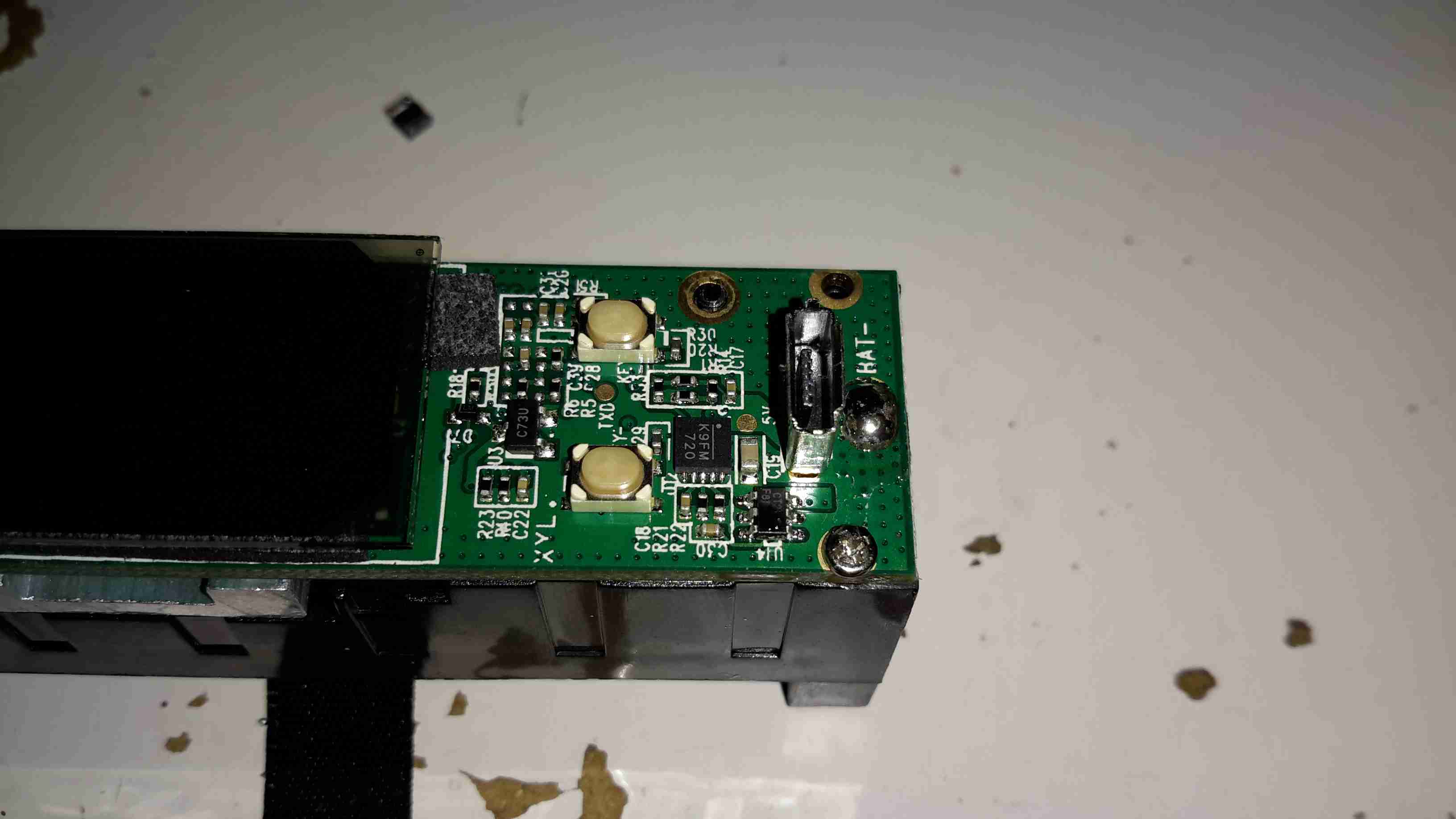
USB Jack
On the right side of the board is the USB jack for charging & firmware updates. The adjustment buttons are also at this end.
Output
On the left side of the board is the main output connector & the fire button. Unlike many eCigs I’ve torn down before, the wiring in this one is very beefy – it has to be to handle the high currents used with some atomizers – up to 10A.
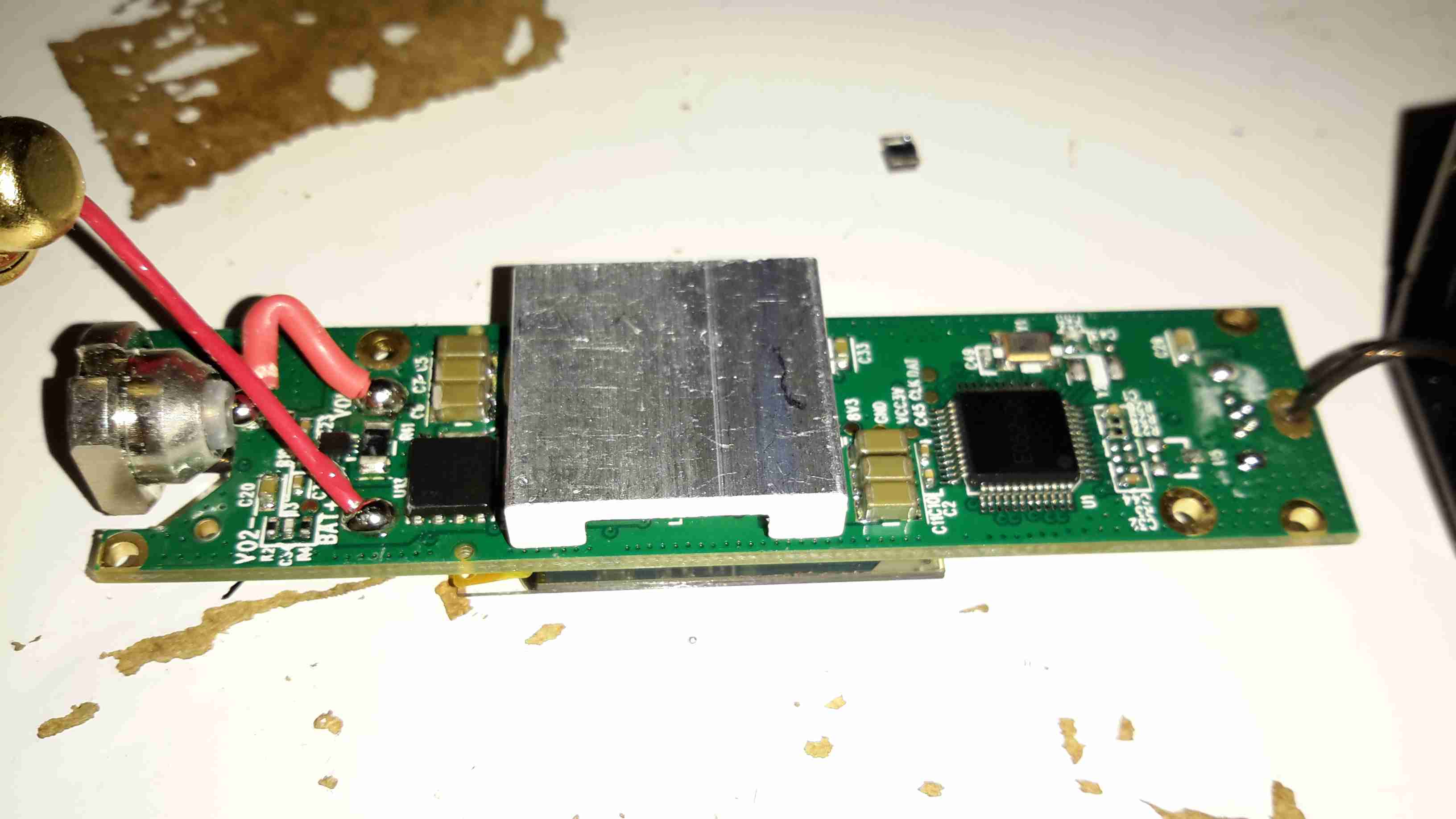
PCB Reverse
Removing the board from the battery holder shows the main power circuitry & MCU. The aluminium heatsink is thermally bonded to the switching MOSFETs, a pair under each end. The switching inductor is under the gap in the centre of the heatsink.
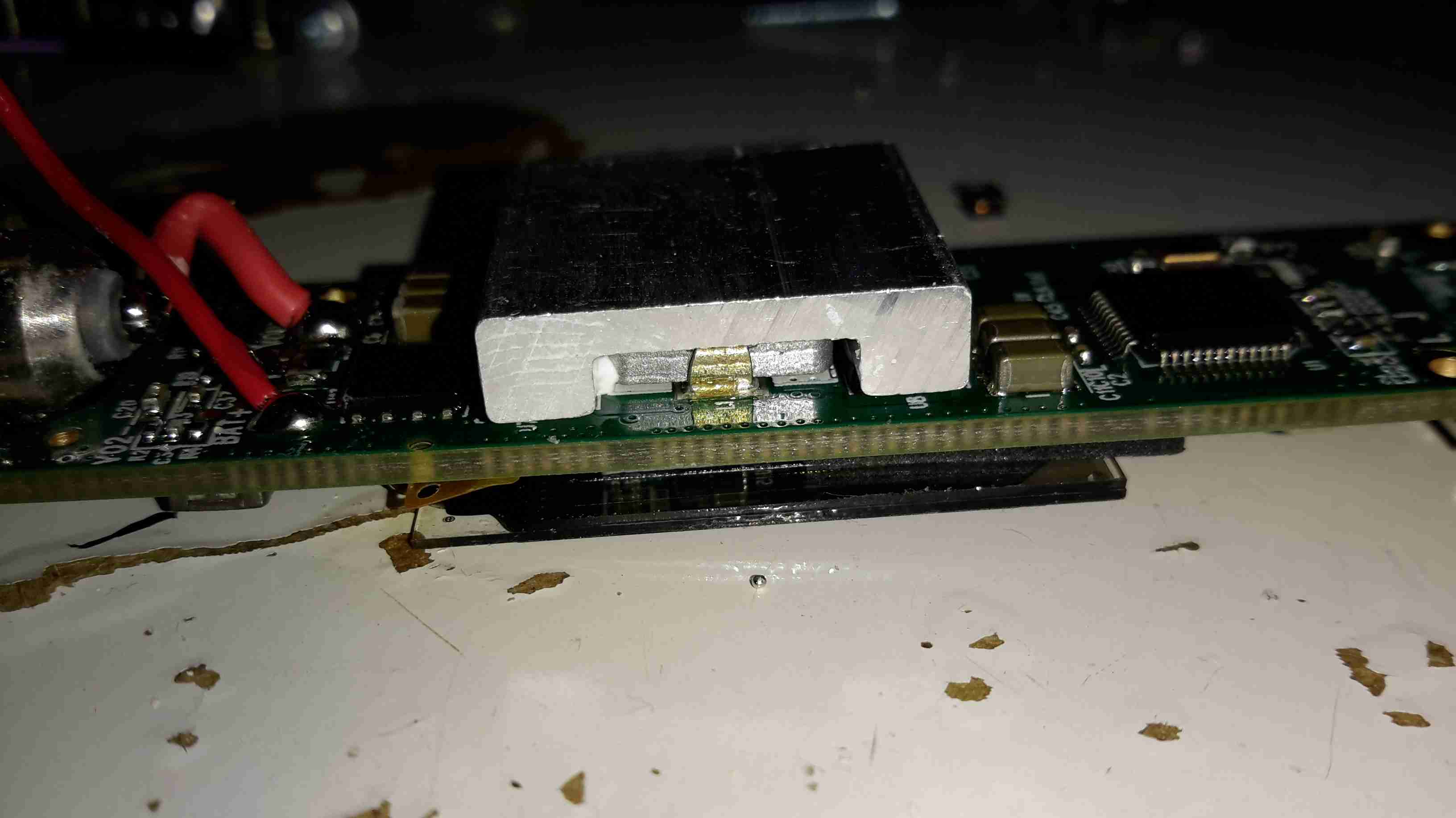
DC-DC Converter
A close up of the heatsink shows the very slim inductor under the heatsink.
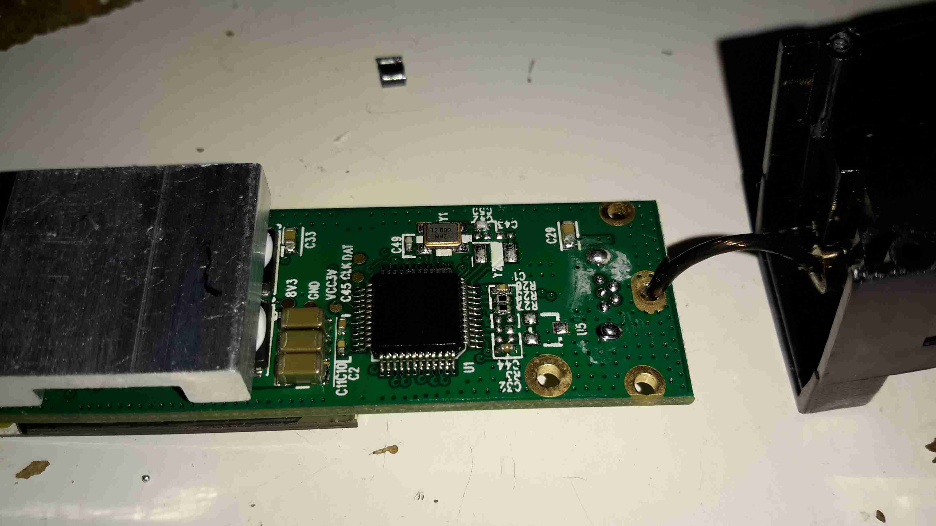
Microcontroller
The main MCU in this unit has a very strange part number, which I’ve been unable to find information on, but it’s probably 8081 based.
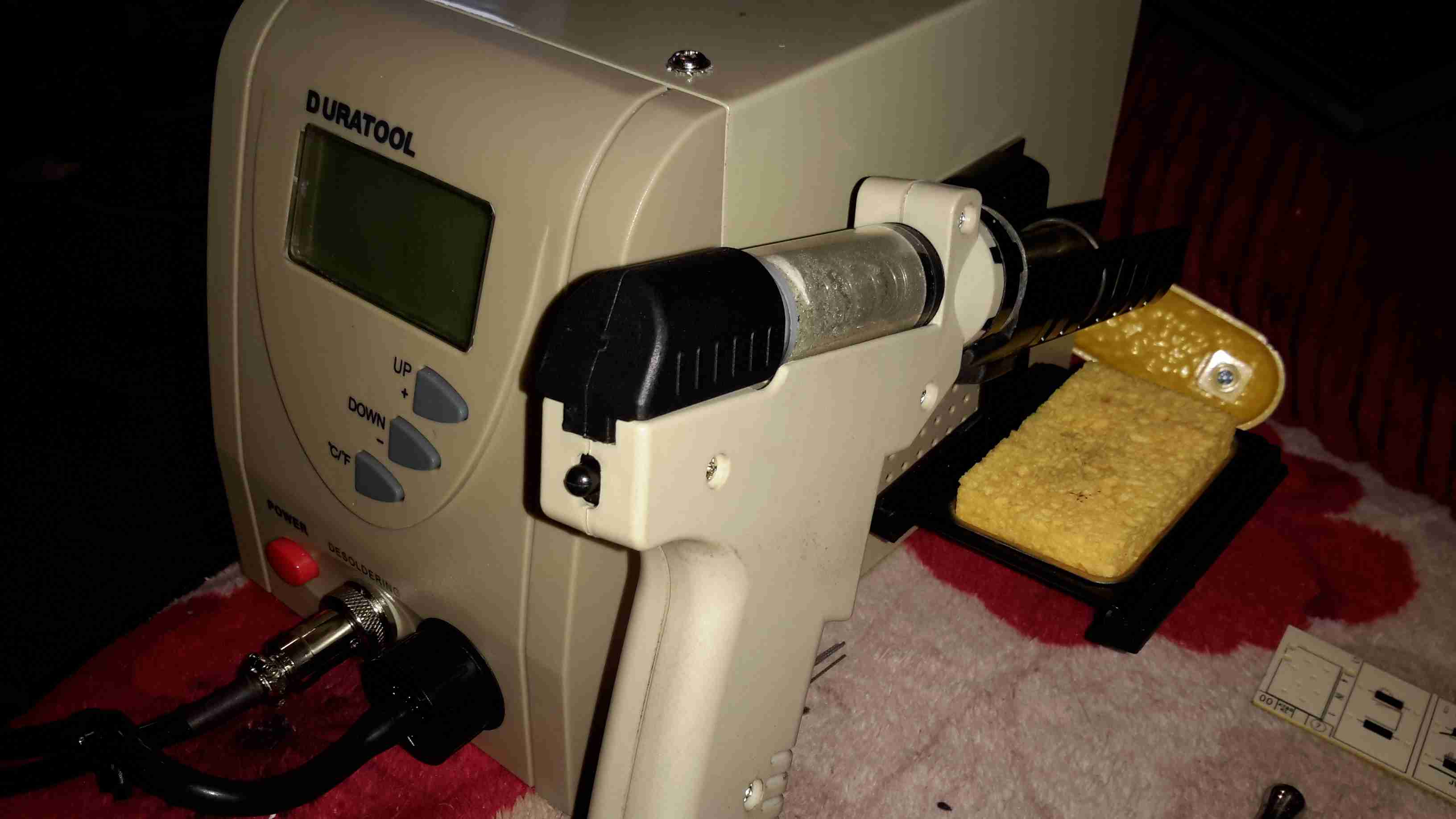
Inkeeping with everything else in my shack being low voltage operated, I had planned from the outset to convert the desoldering station to 12v operation. It turns out this has been the easiest tool to convert in my shack so far.
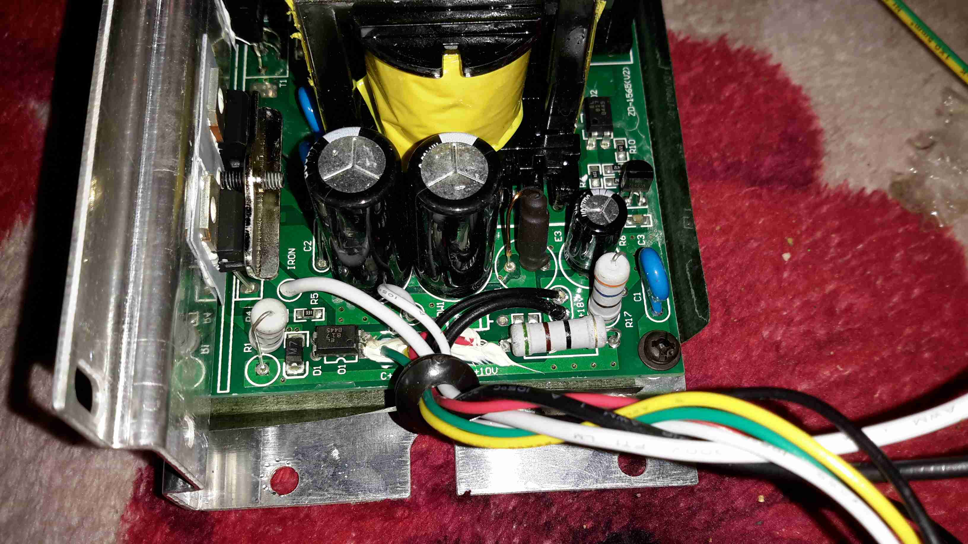
PSU Outputs
The factory SMPS is a fairly straightforward 18v 12A unit, with only a single small oddity: the desoldering gun’s heating element is controlled from inside the supply.
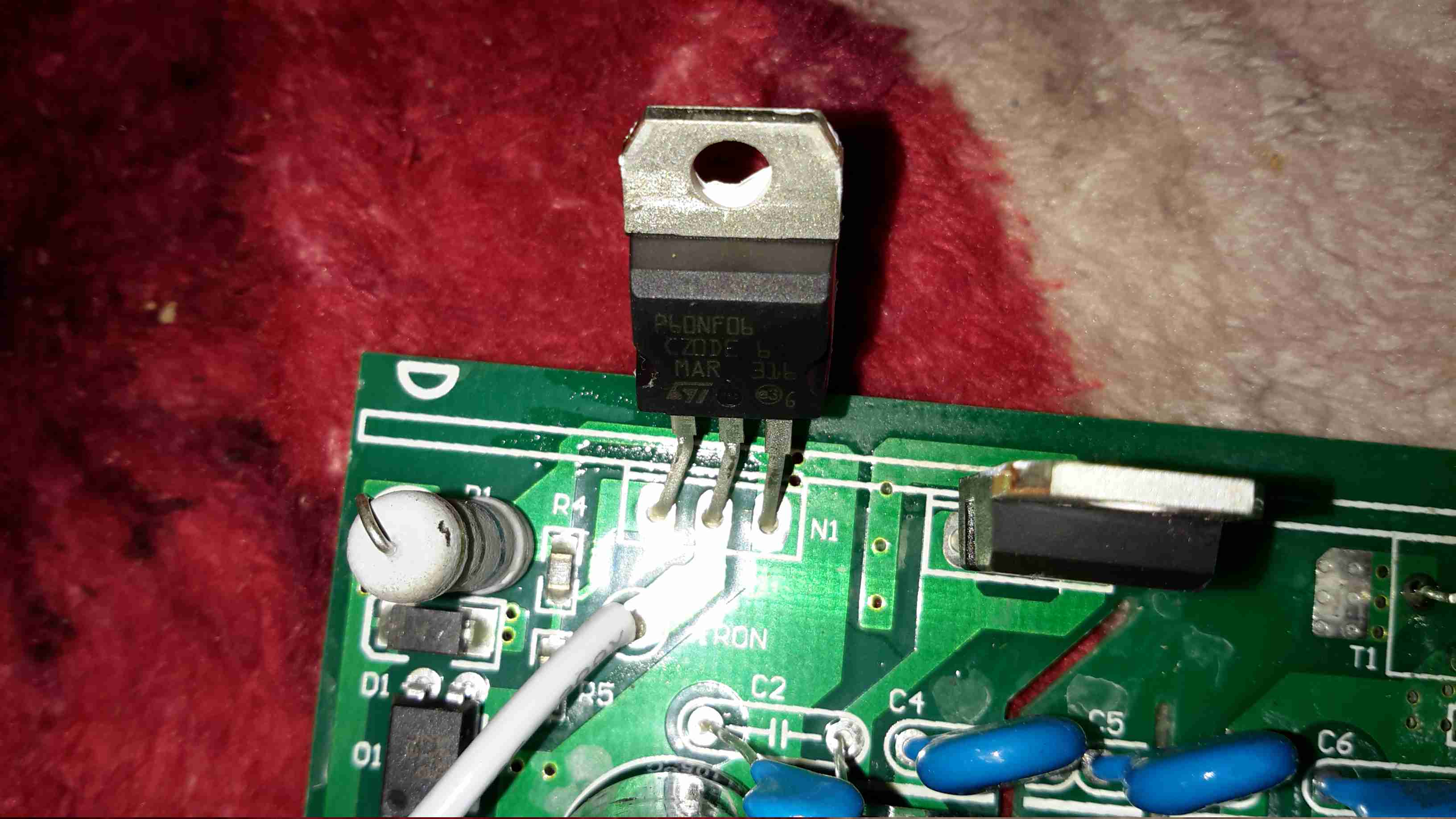
Iron MOSFET
Next to the output rectifier on the heatsink is a large MOSFET, in this case a STP60NF06 from ST Micro. This is a fairly beefy FET at 60v & 60A capacity, RDS On of <0.016Ω.
This is driven via an opto-isolator from the main logic board. I’ve not yet looked at the waveform on the scope, but I suspect this is also being PWM’d to control temperature better when close to the set point.
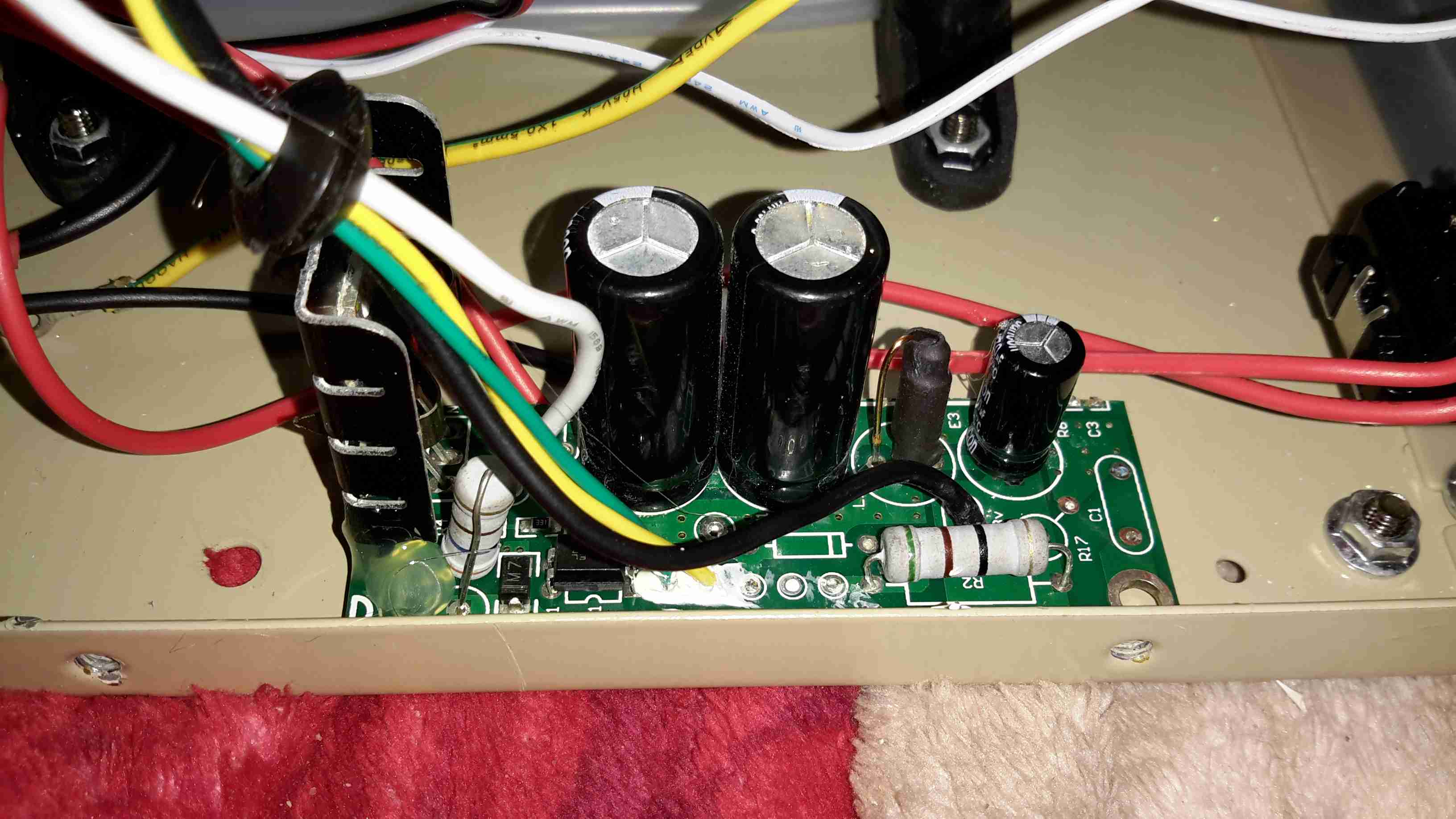
Iron Element Controller
Rather than fire up the soldering iron & build a new element controller circuit (Lazy Mode™), I opted to take a saw to the original power supply. I cut the DC output section of the PCB off the rest of the supply & attached this piece back to the frame of the base unit. I also added a small heatsink to the MOSFET to make sure it stays cool.
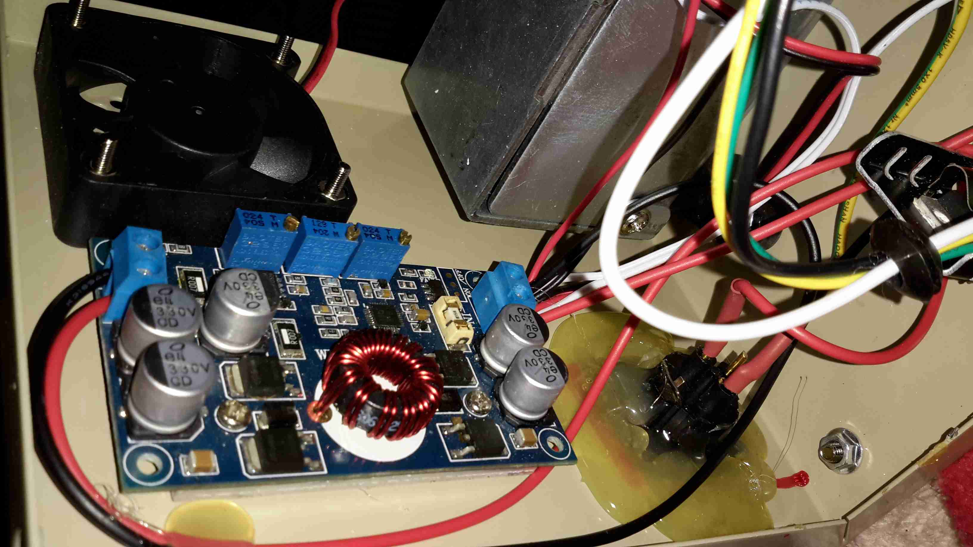
12v Power Supply
Since the fan & vacuum pump are both already 12v rated, those are connected directly to the DC input socket, that I’ve installed in place of the original IEC mains socket. The 18v for the heating element is generated by a 10A DC-DC converter, again from eBay.
Oddly, the iron itself is rated at 24v 80W, but the factory supply is only rated to 18v. I’m not sure why they’ve derated the system, but as the station already draws up to 10A from a 13.8v supply, increasing the voltage any further would start giving my DC supplies a problem, so it can stay at 18v for now.
For a long time I’ve needed a decent vacuum desoldering tool, as I do much stripping of old PCBs for random parts.
Solder wick works well for most things, but it’s expensive & can be fiddly. It also doesn’t keep very long as the copper braid oxidises & after that point it never seems to work particularly well, even when soaked in fresh flux.
Desoldering Station
As usual eBay to the rescue! I managed to pick this one up for £80.
Vacuum Pump
Removing the lid reveals the internals. Front & centre is the vacuum pump, with the mains supply behind it. There’s also a very noisy cooling fan at the back. Not sure why since the unit never gets warm enough to actually warrant a fan.
PSU
On the other side is the PSU. This is an 18v 12A rated SMPS, with a bit of custom electronics for controlling the iron element. Mounted to the back case is a small black box, more to come on this bit.
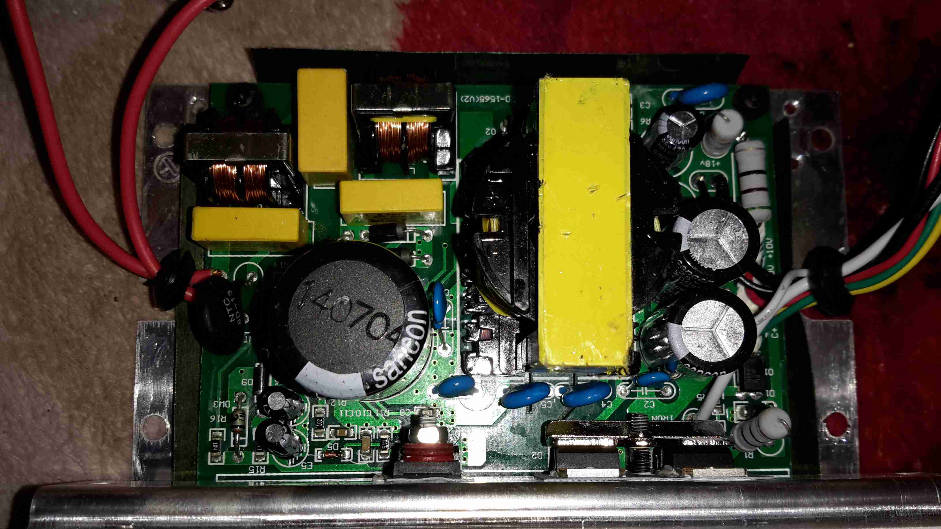
PSU Board
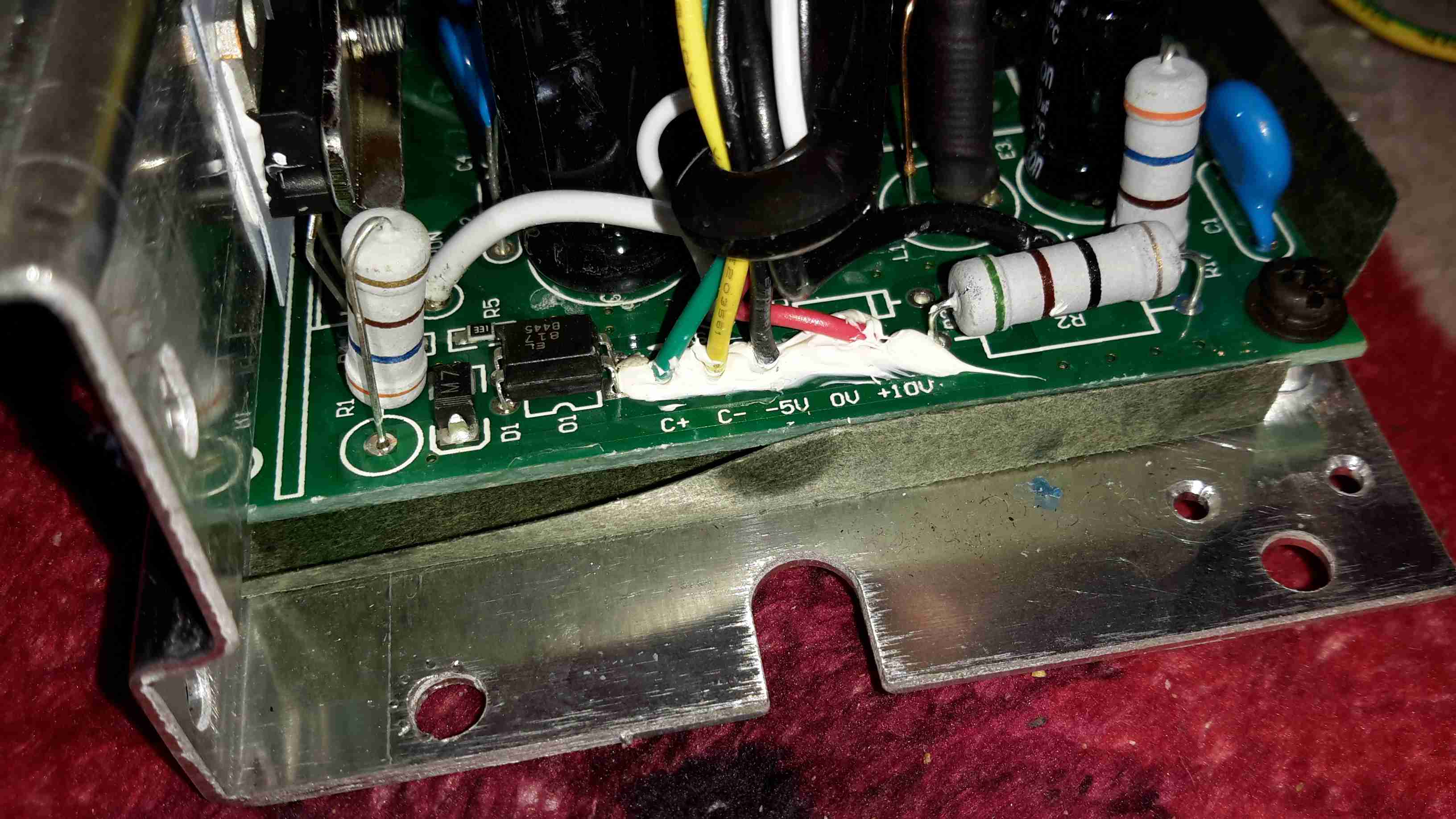
Cracking the case of the PSU reveals a pretty bog-standard SMPS, with a surprising amount of mains filtering for a Chinese supply. The DC outputs are on the right.
From the rail markings, this is clearly designed to output some more voltage rails – possibly for other models of unit. In this case though, a single 18v rail is present. The iron’s element connects directly to the supply, controlled via an opto-isolated MOSFET.
Chinese Voltage Regulation
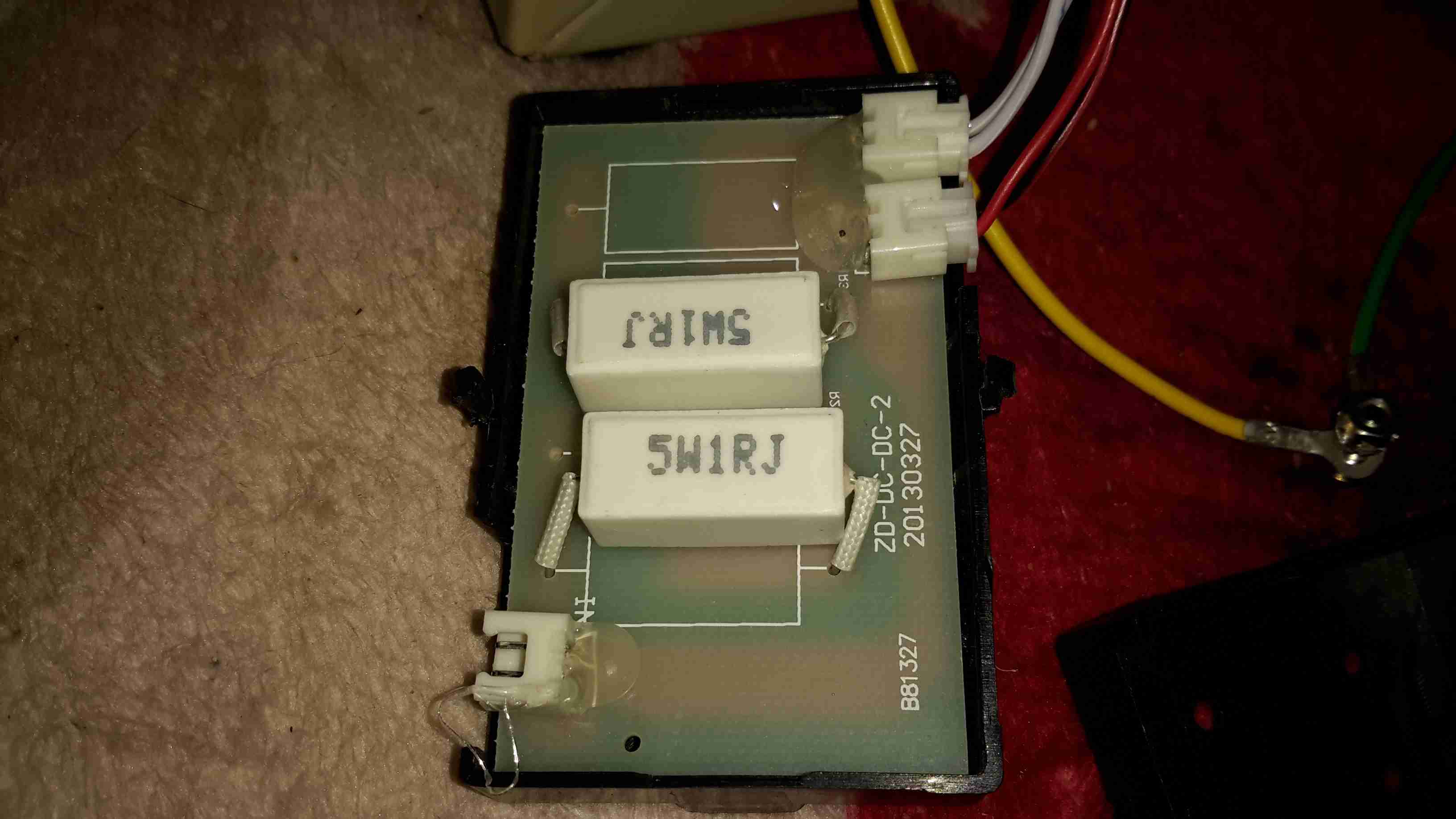
As both the fan & the vacuum pump motor are 12v devices, some provision had to be made to reduce the 18v from the power supply to a more reasonable value. Inside the black plastic box are a pair of 1Ω 5W power resistors, connected in series. The output from this connects to the fan & vacuum pump. Because cheap, obviously.
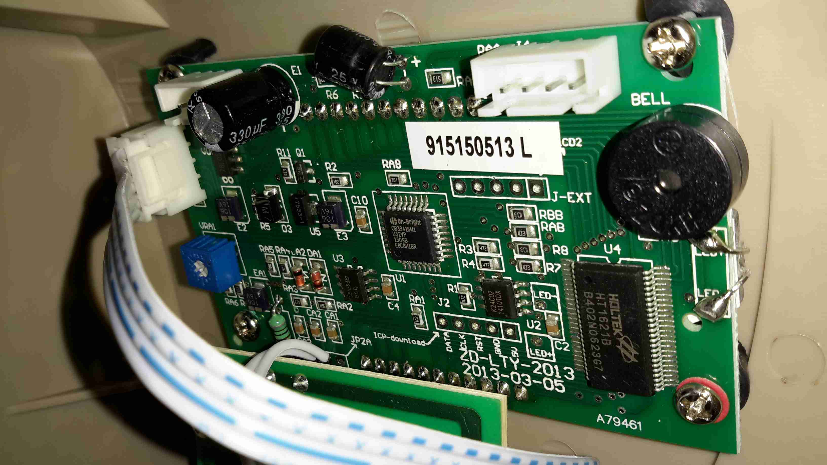
Controller
Finally, here’s the controller PCB, the main MCU is an 8081 derivative, with a Holtek HT1621B LCD controller for the front panel temperature readout. Iron temperature is achieved by a thermocouple embedded in the heater, I imagine the potentiometer on the left side of the PCB is for calibration.
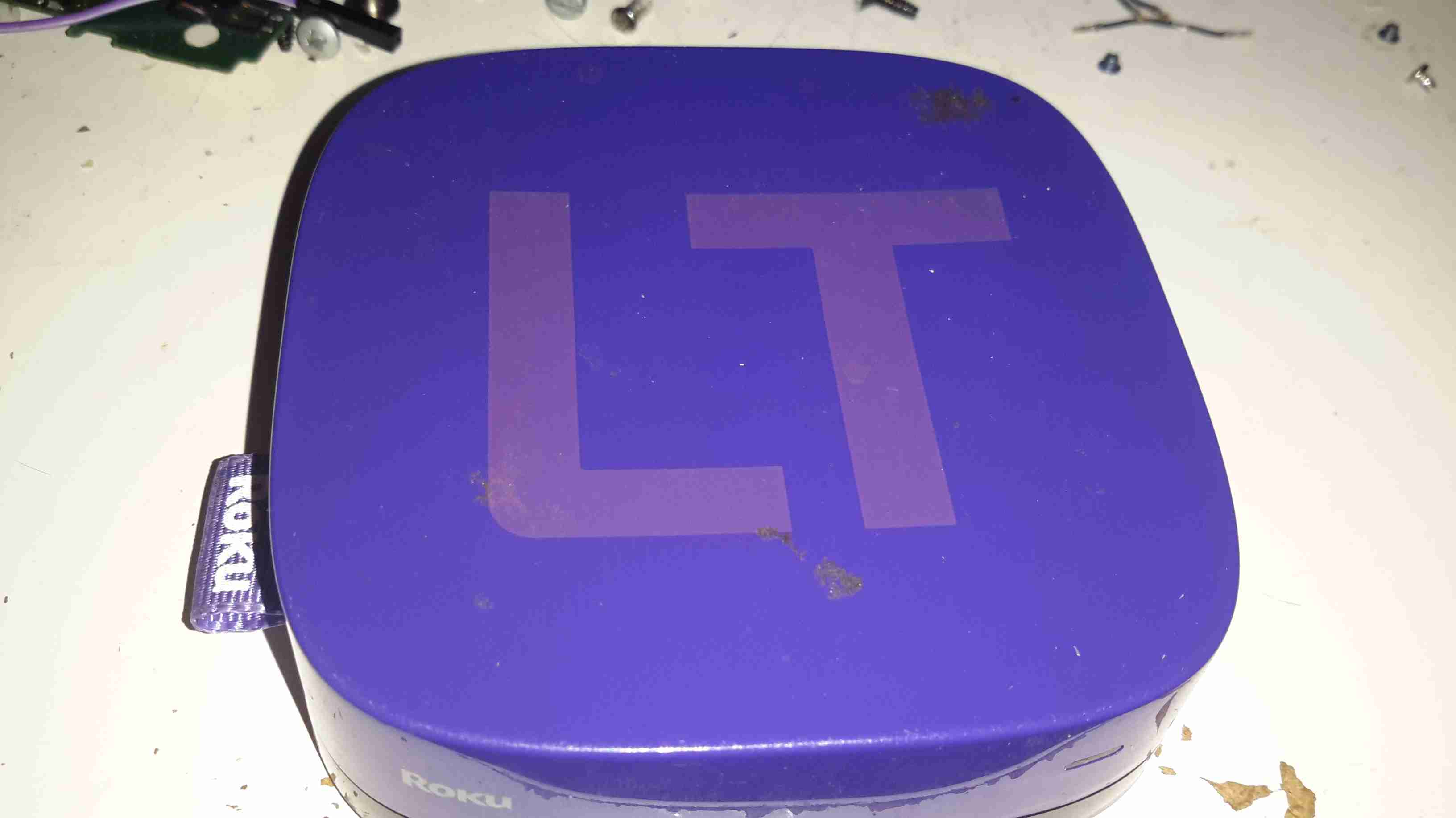
Here’s another retired piece of tech that we used to route media from the NAS to the main TV. It was retired since it’s inability to support XBMC/Kodi & having some crashing issues.
Main PCB
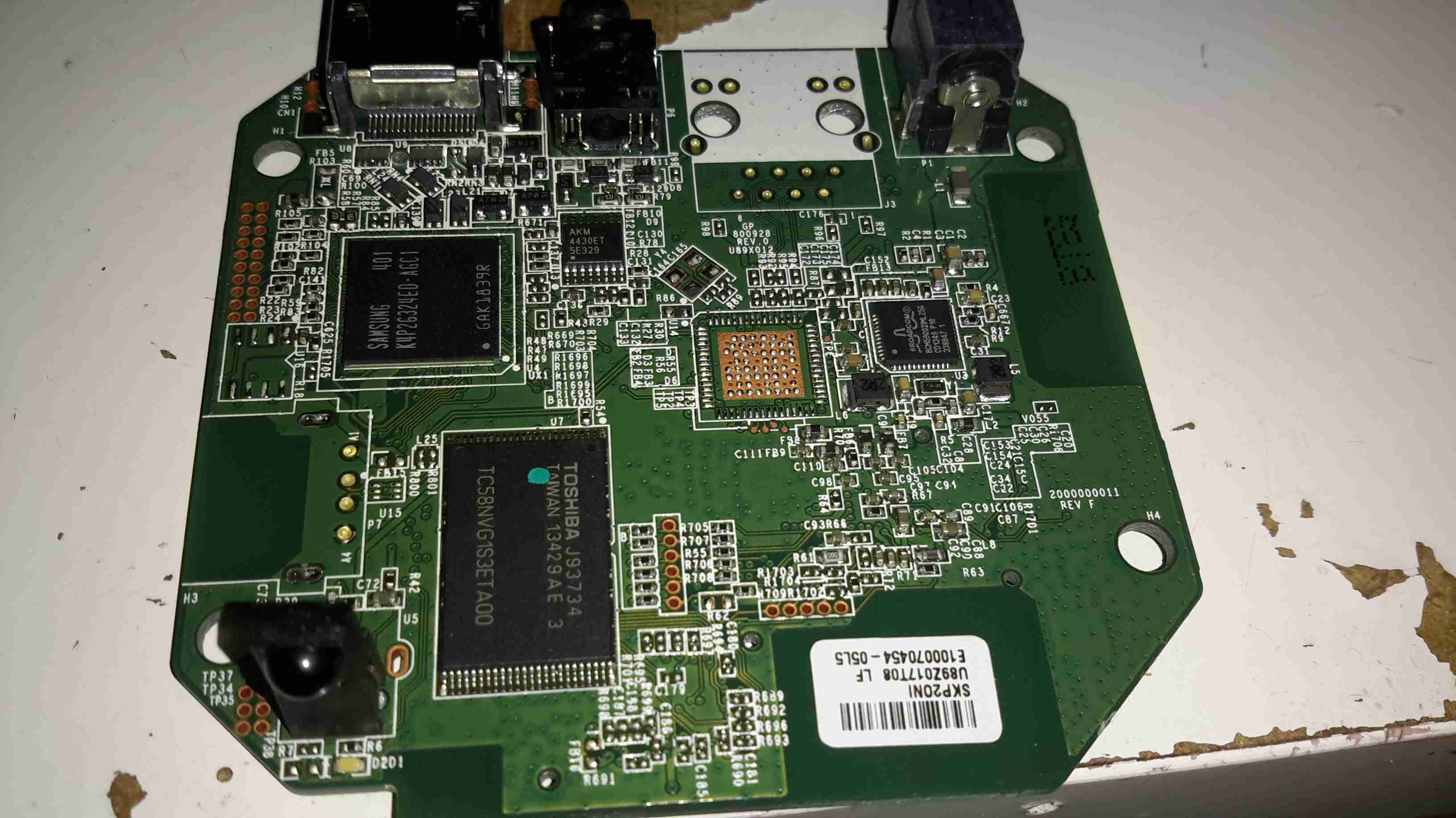
After attacking the case with the screwdriver (Torx in this case), the main board comes out. The CPU in this looks *very* familiar, being a PoP device. There are unpopulated places for an ethernet interface & USB port here.
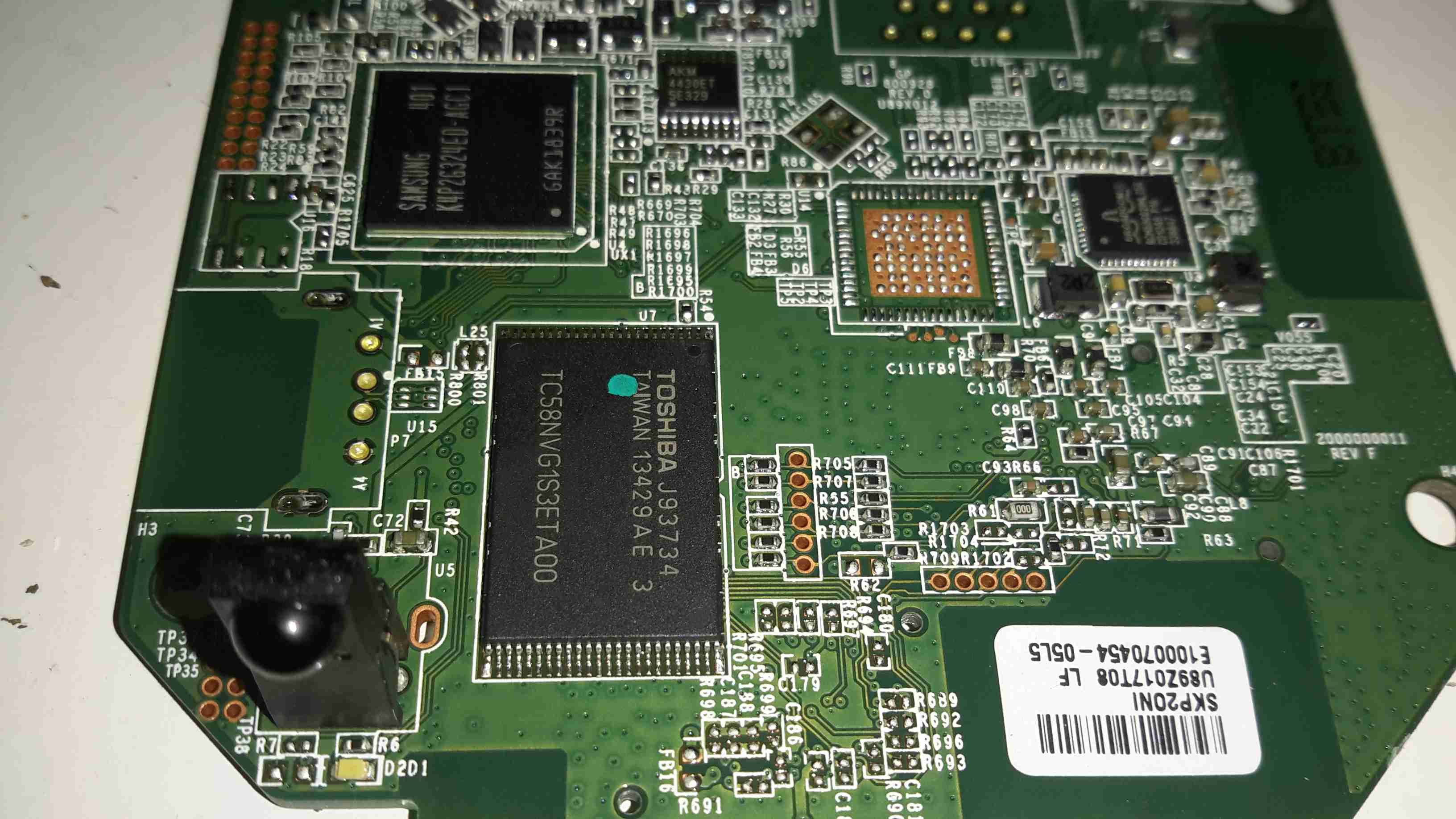
Flash & CPU
After a little digging is turns out the CPU in this device is a BCM2835, with 256MB of RAM stacked on top. It’s a Raspberry Pi! Even the unpopulated part for Ethernet is the same SMSC LAN9512!
There’s 32MB of Flash for the software below the CPU.
On the far right of the board is a Broadcom BCM59002IML Mobile Power Management IC.
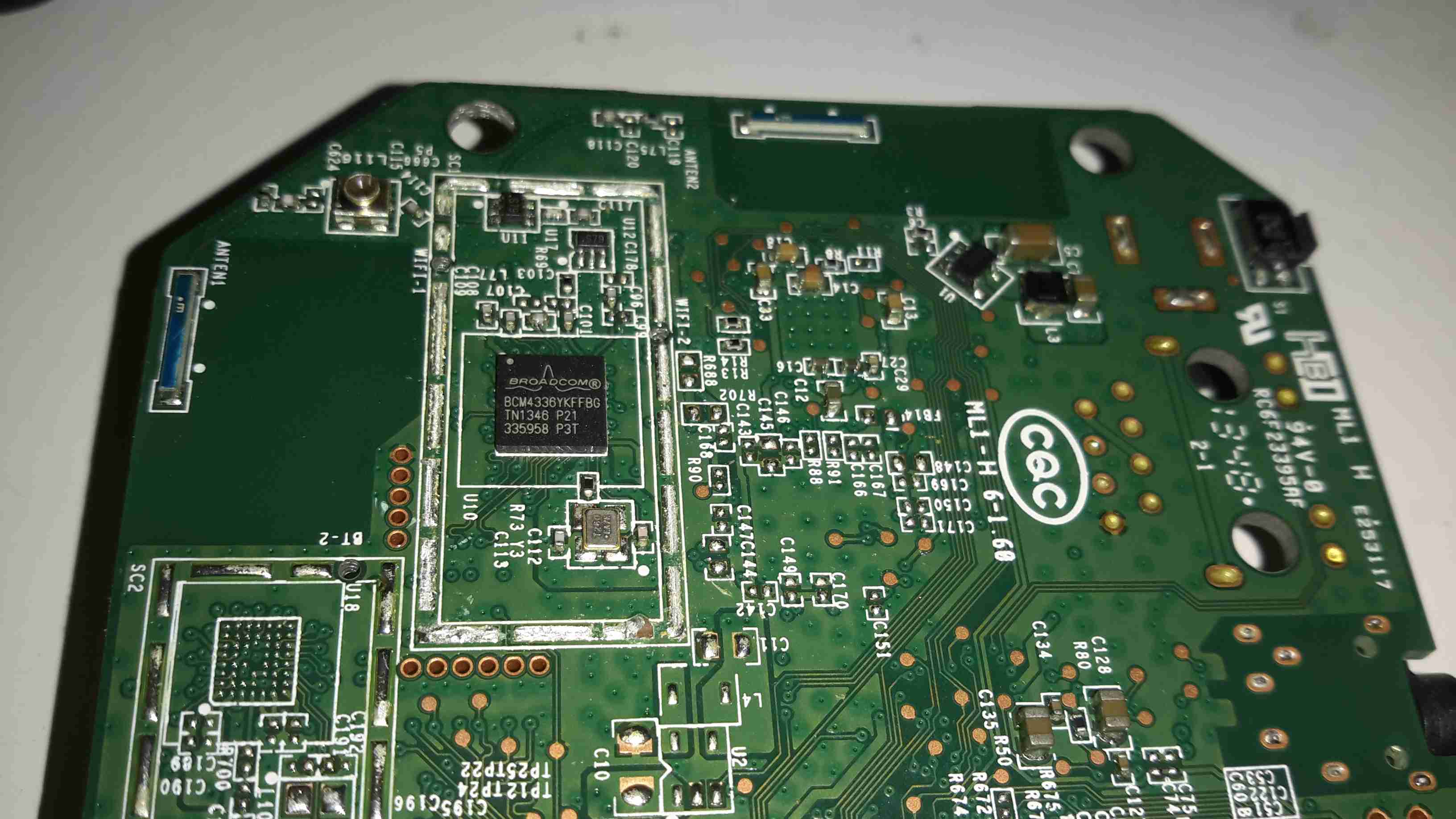
WiFi Chipset
On the bottom of the PCB is the WiFi chipset, a Broadcom BCM4336, this most likely communicates with the CPU via SDIO. There’s also a section below for a Bluetooth chipset.
For a while I’ve wondered how these pancake type (AKA “Shaftless”) vibration motors operate, so I figured I’d mutilate one to find out.
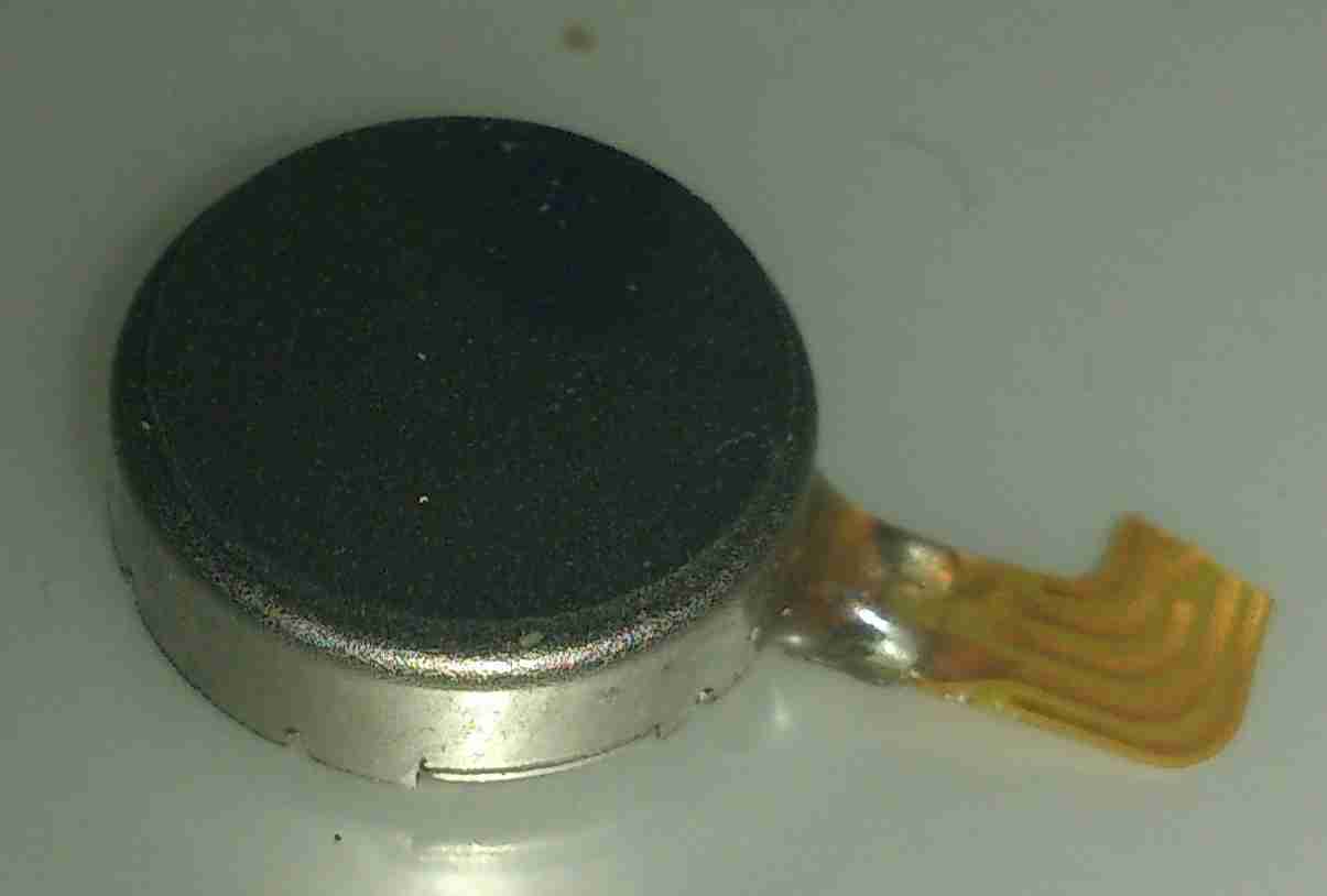
Pancake Vibration Motor
These vibrators are found in all kinds of mobile devices as a haptic feedback device, unlike older versions, which were just micro-sized DC motors with an offset weight attached to the shaft, these don’t have any visible moving parts.
Cover Removed
These devices are crimped together, so some gentle attack with a pair of snips was required to get the top cover off.
It turns out these are still a standard rotary DC motor, in this case specifically designed for the purpose. The rotor itself is the offset weight, just visible under the steel half-moon shaped section are the armature coils.
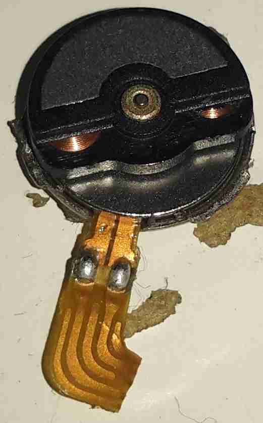
Weighted Rotor
The armature lifts off the centre shaft, the coils can clearly be seen peeking out from under the counterweight.
Commutator
The underside of the armature reveals the commutator, which in this device is just etched onto the PCB substrate, the connections to the pair of coils can be seen either side of the commutator segments.
Brushes
The base of the motor holds the brushes in the centre, the outer ring is the stationary permanent magnet. These brushes are absolutely tiny, the whole motor is no more than 6mm in diameter.
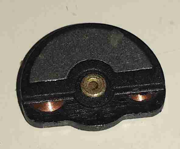
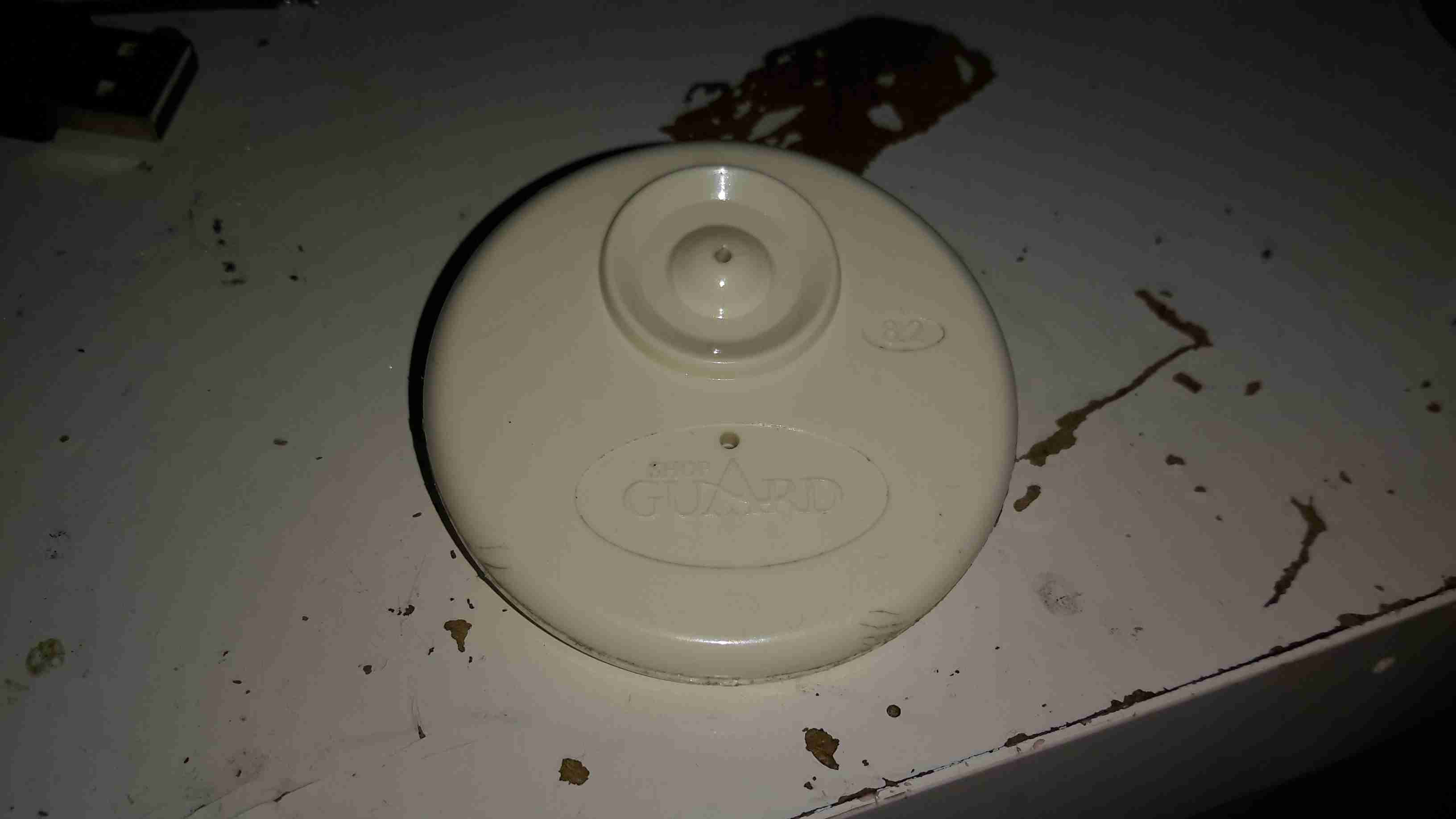
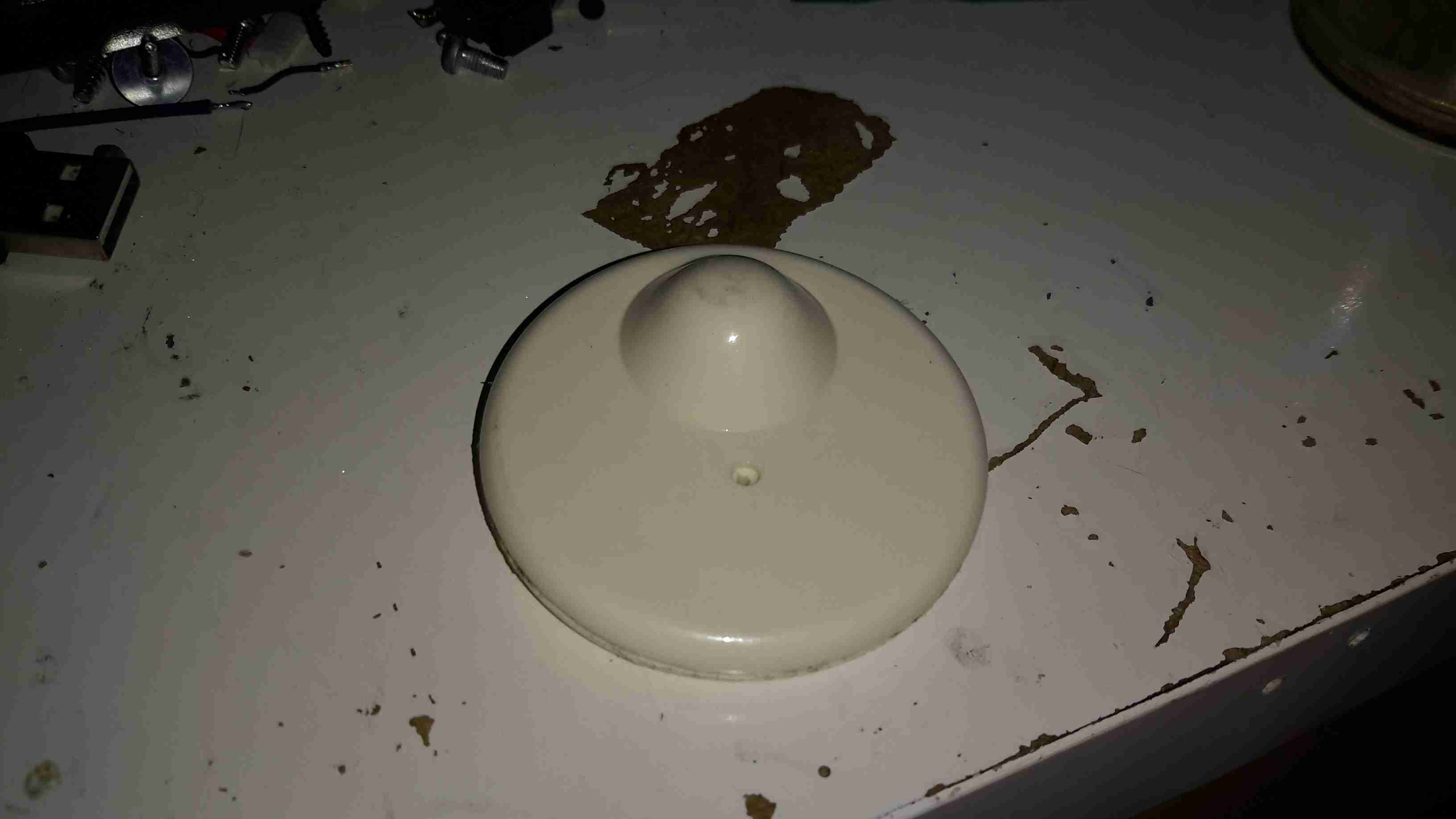
Everyone at some stage must have seen these EAS security tags in shops, usually attached to clothing with a steel pin. As some of this year’s presents had been left with the tags attached, I had to forcibly remove them before wrapping could commence.
Reverse Side
These are just a plastic disc about 50mm in diameter, with an internal locking mechanism & RF tag inside.
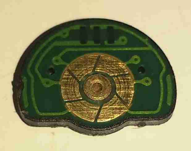
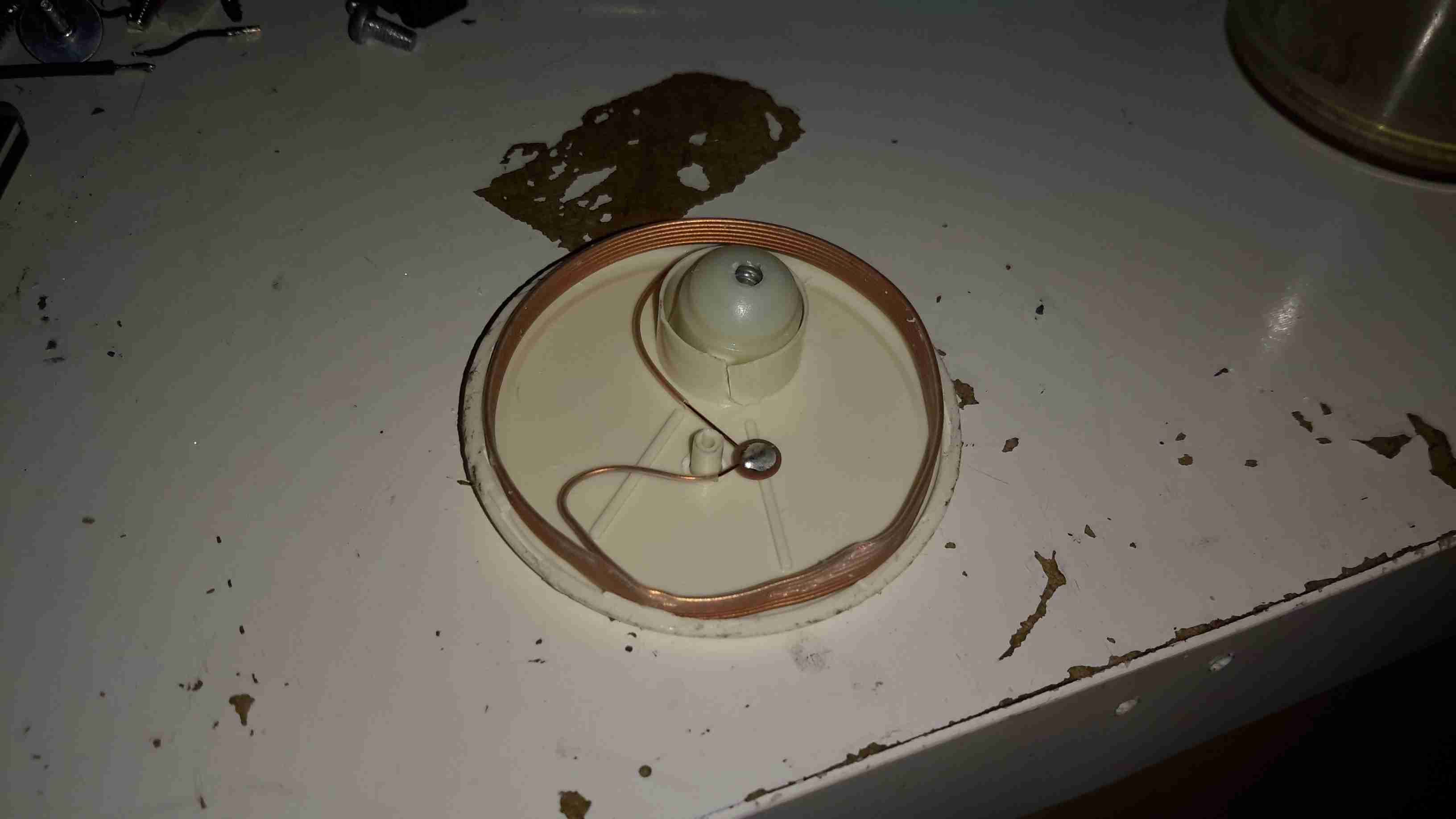
RF Coil
After some careful attack with a saw around the glue seam, the tag comes apart into it’s halves. The RF coil & it’s ceramic capacitor can be seen wrapped around the outside of the tag. The capacitor in this case isn’t even epoxy dipped to save that extra 0.0001p on the manufacturing price. In the top centre is the pin locking mechanism, enclosed in a small plastic pill.
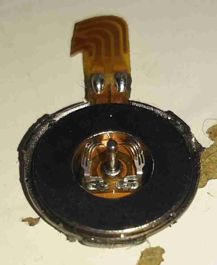
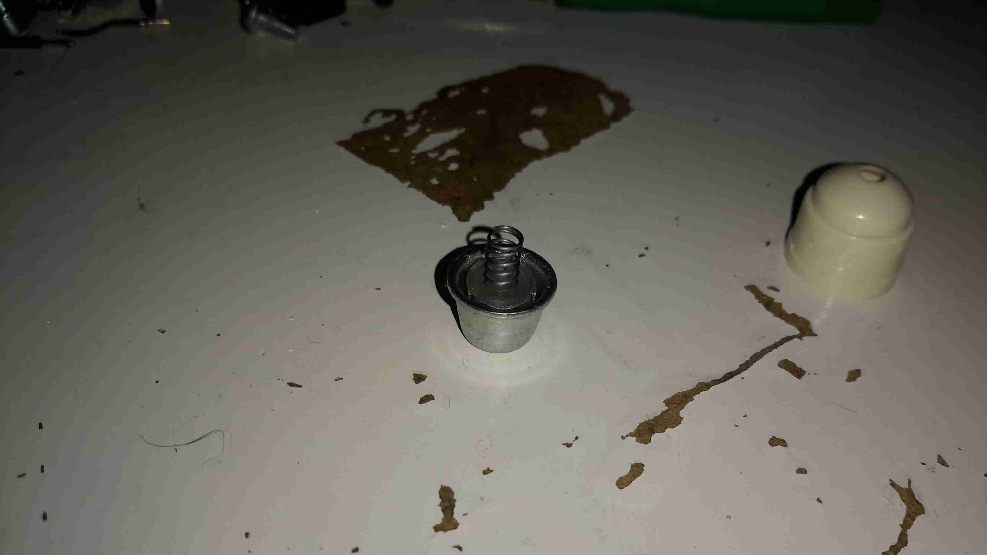
Lock Pill
Popping off the back cap of the lock shows it’s internals.
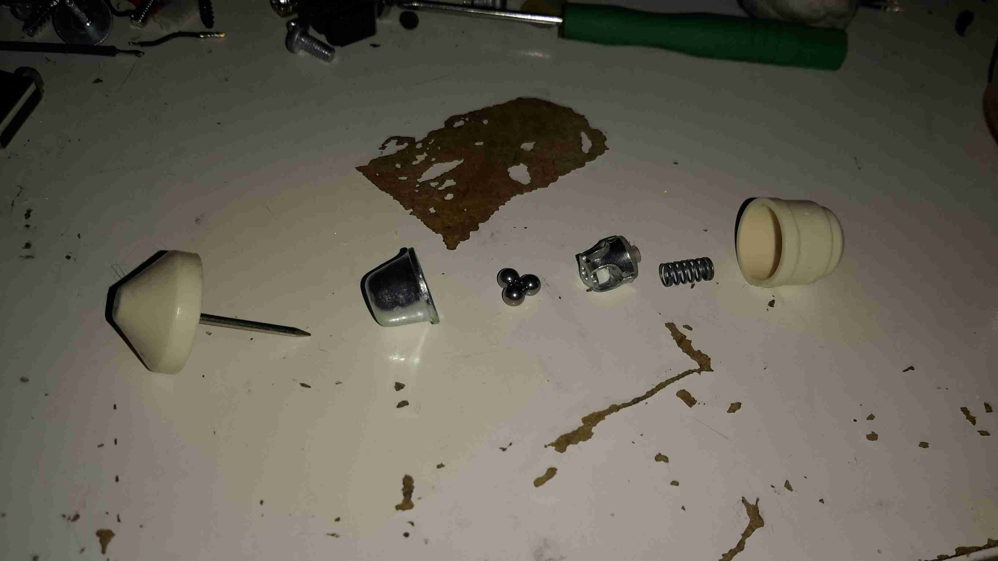
Ball Bearing Lock Assembly
The lock itself is very simple. The centre section, held in place by a spring, carries 3 small ball bearings. The outer metal frame of the lock is conical in shape.
When the pin is pushed into the tag, the conical shape of the lock chamber causes the ball bearings to grab onto it, helped by the action of the spring that pushes the ball bearing carrier further into the cone.
This also means that any attempt to force the mechanism causes it to lock tighter onto the pin.
In normal operation, removal is achieved by a strong magnet that pulls the ball bearing carrier back slightly against it’s spring, allowing the pin to disengage & be pulled out.
This design is incredibly simple & cheap to make, and gains it’s locking strength from friction alone.
I would consider the RF coil being around the outer edge of the device a bit of a security risk – a quick chop with a sharp pair of wire cutters would disable the tag’s alarm functionality instantly. Making the coil slightly smaller & keeping it out of reach of the edge of the tag would help in this regard.
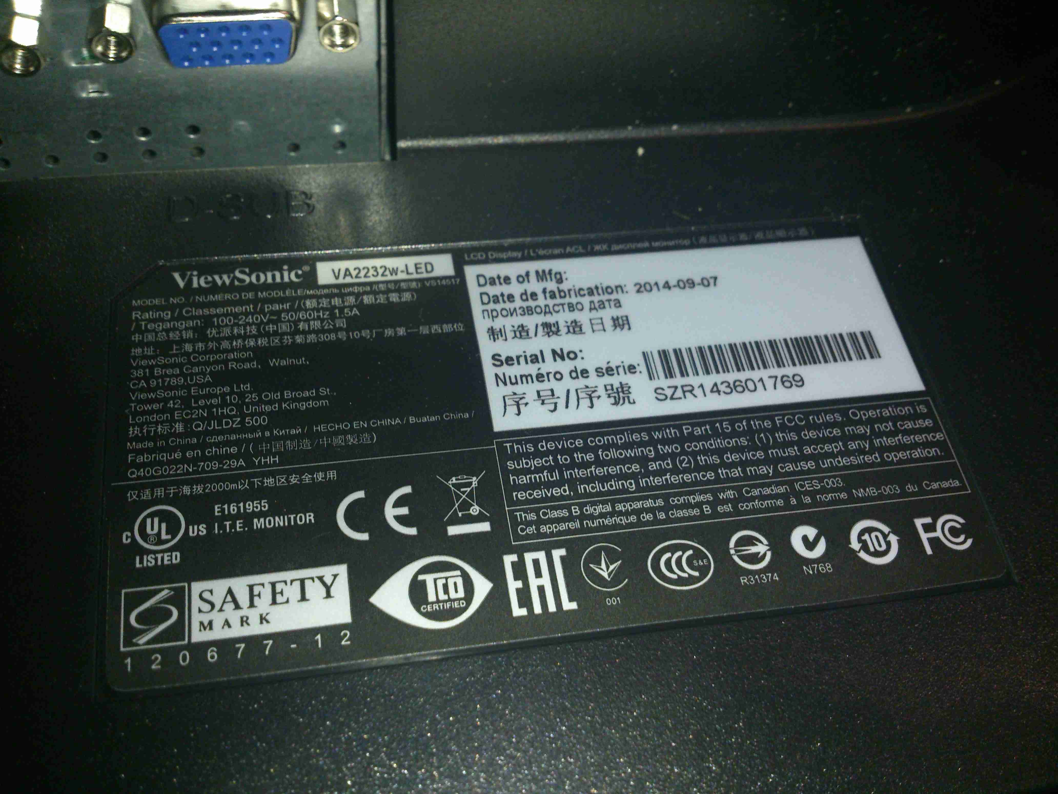
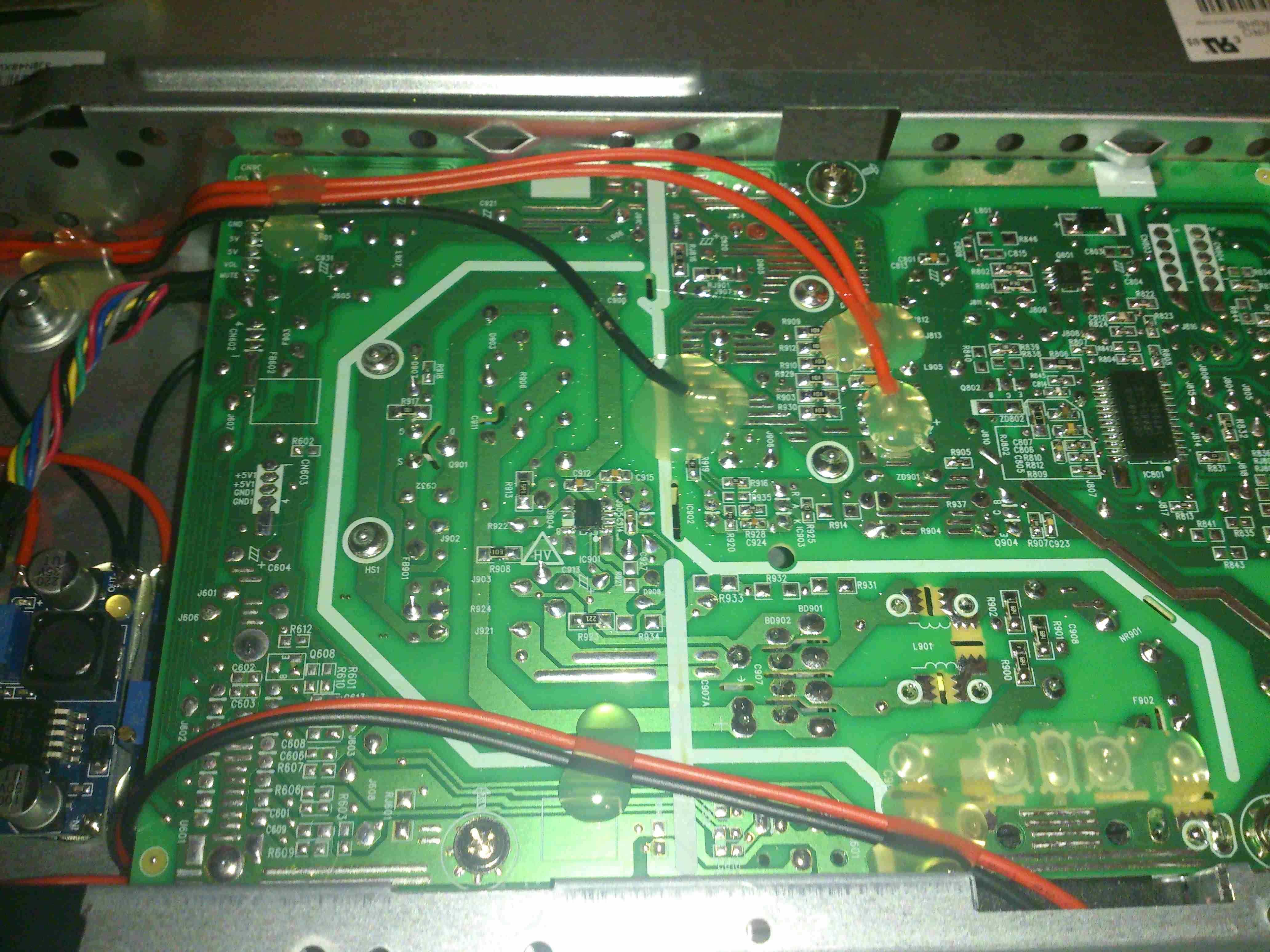
On the quest to get things on board replaced that are heavy users of power, the monitor in the main cabin was next. The original CCFL-backlit monitor was very heavy on 12v power, at 5A. This meant falling asleep watching TV would result in severely flattened batteries.
Replacement with a suitable LED-backlit monitor was definitely required. The cheapest on eBay was a ViewSonic VA2232W-LED, so I took to work converting it from 240v to 12v operation.
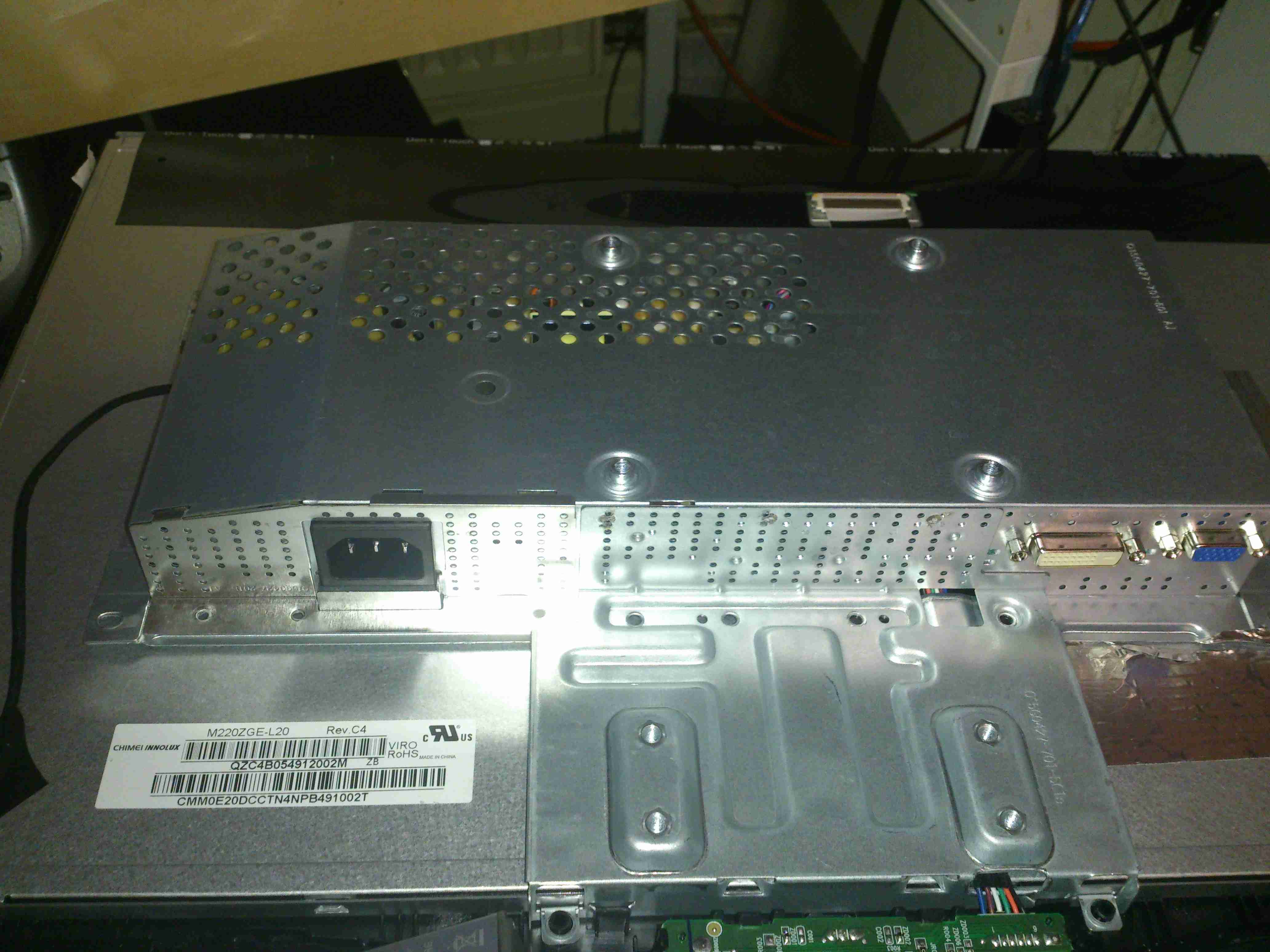
Back Cover Removed
There are no screws holding these monitors together, so a spudger & frequent swearing got the back off. The shield holding the circuitry is also not screwed down, only attached to the back of the LCD panel with aluminium shielding tape.
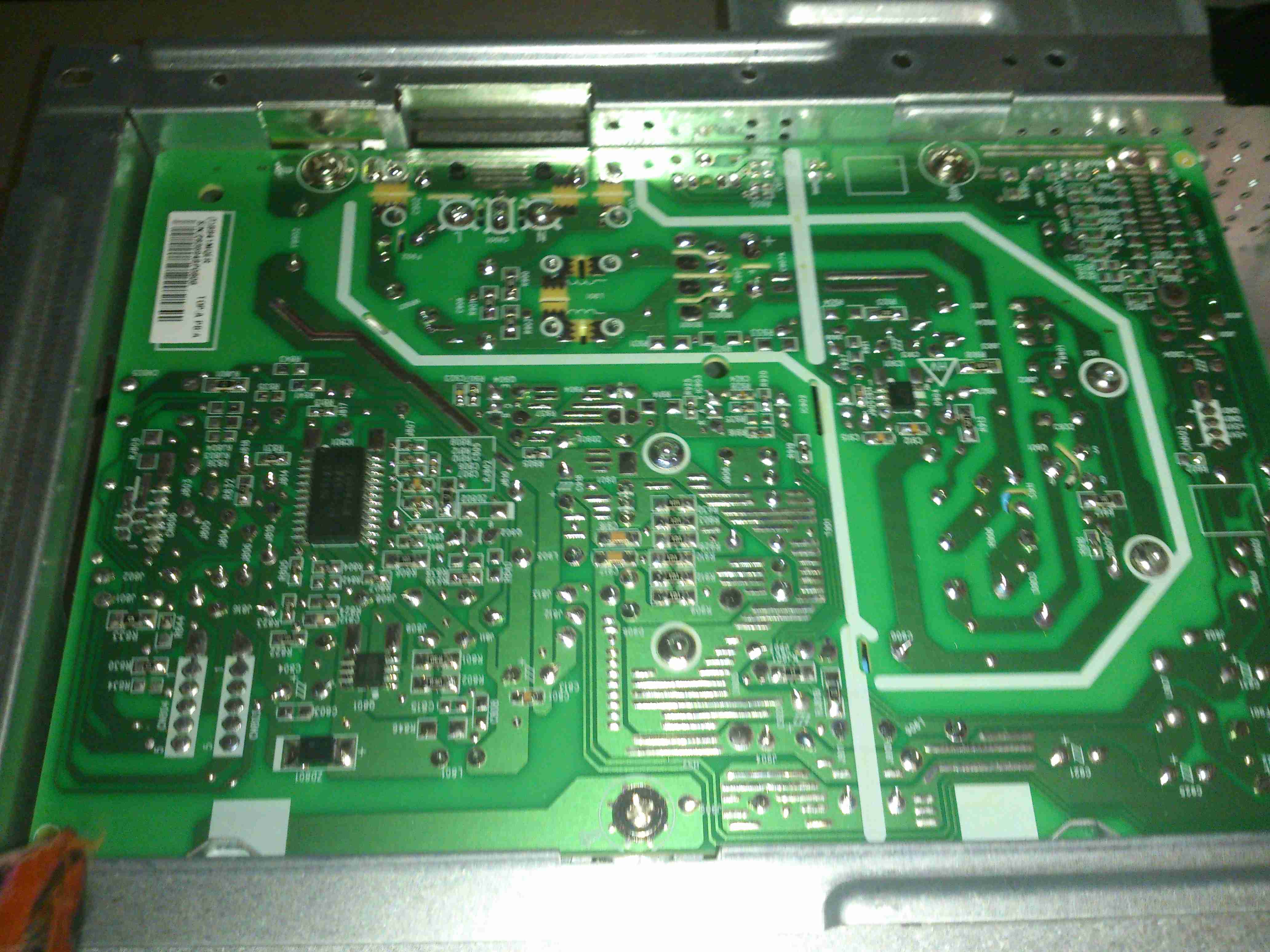
Power PCB Trackside
Once the tape has been cut, the main power board is accessible. The large IC on the left is the main backlight LED driver.
In this case the monitor requires a pair of rails from the supply, 18.5v for the backlight circuitry & 5v for the logic.
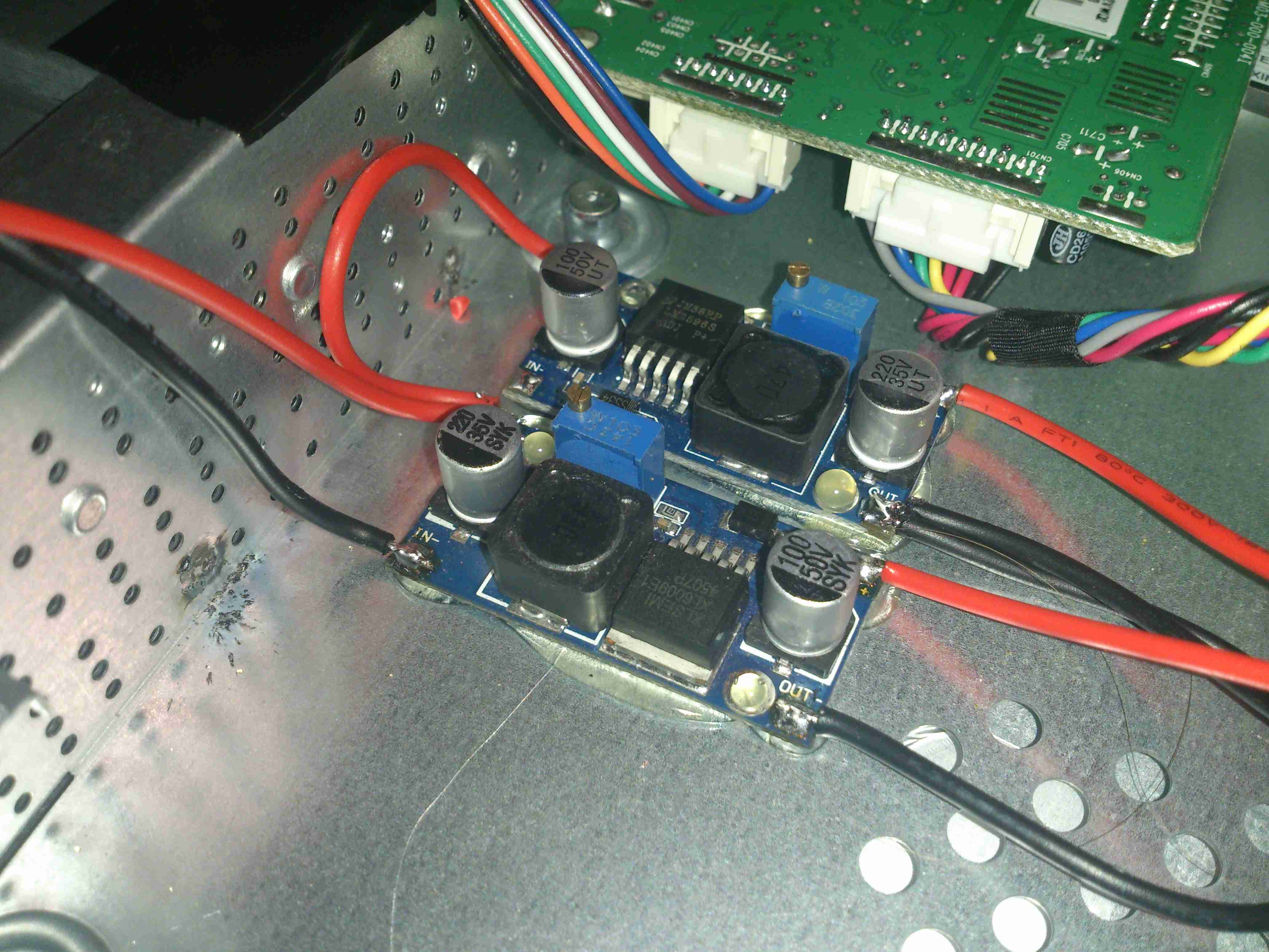
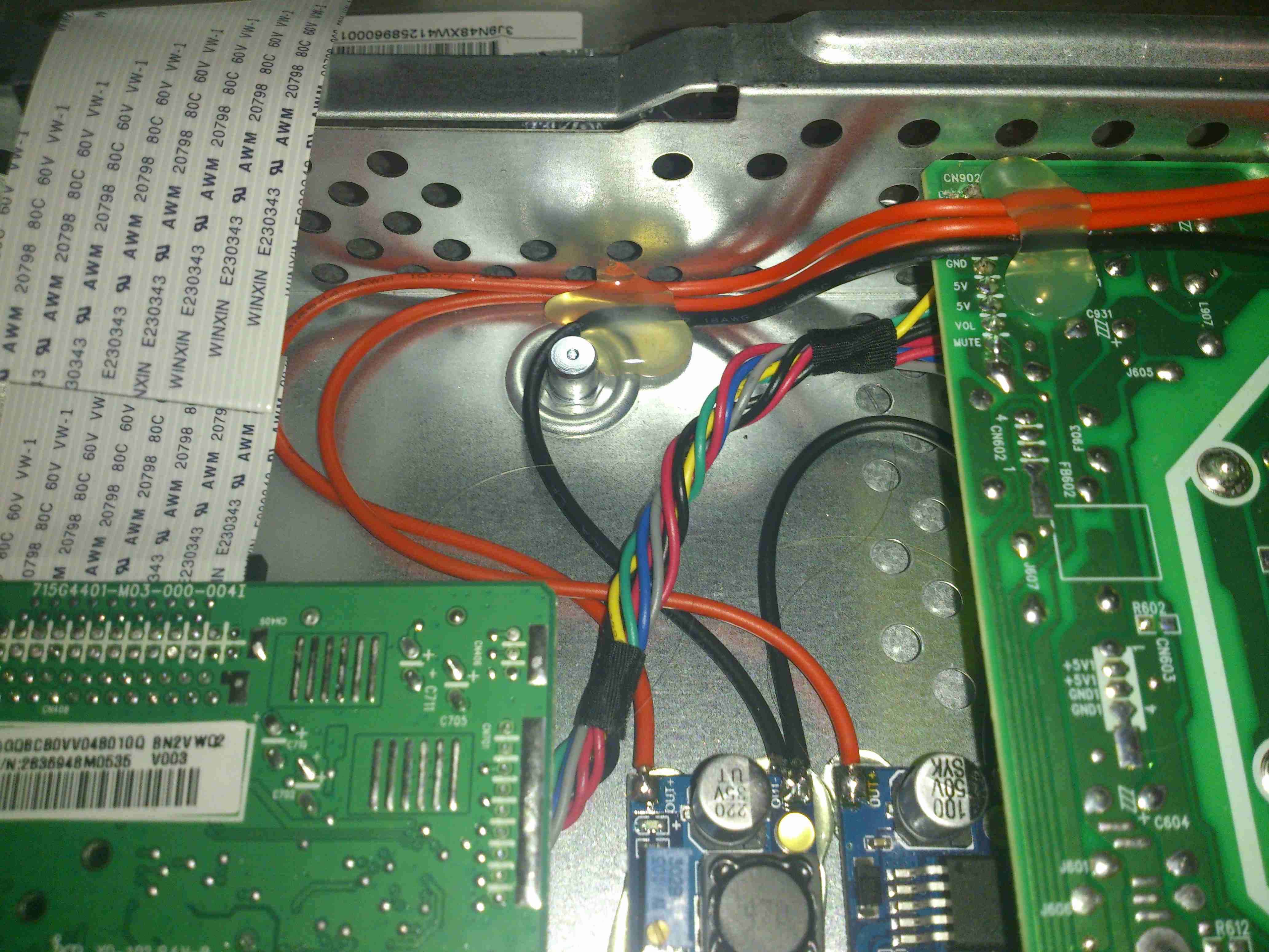
DC-DC Regulators
A pair of DC-DC converters has been fitted in the small space between the power & control boards.
PCB Connection Points
To save me some work & keep maximum compatibility, I’ve not modified the existing supply, just attached the new DC-DC converter outputs onto the corresponding outputs of the factory PSU. The 12v input leads are routed out of the same gap as the mains IEC connector, with some hot glue over the mains input solder points to provide some more insulation.
Wiring Tidied
The wiring is tidied up with hot glue so the back cover will go back on.
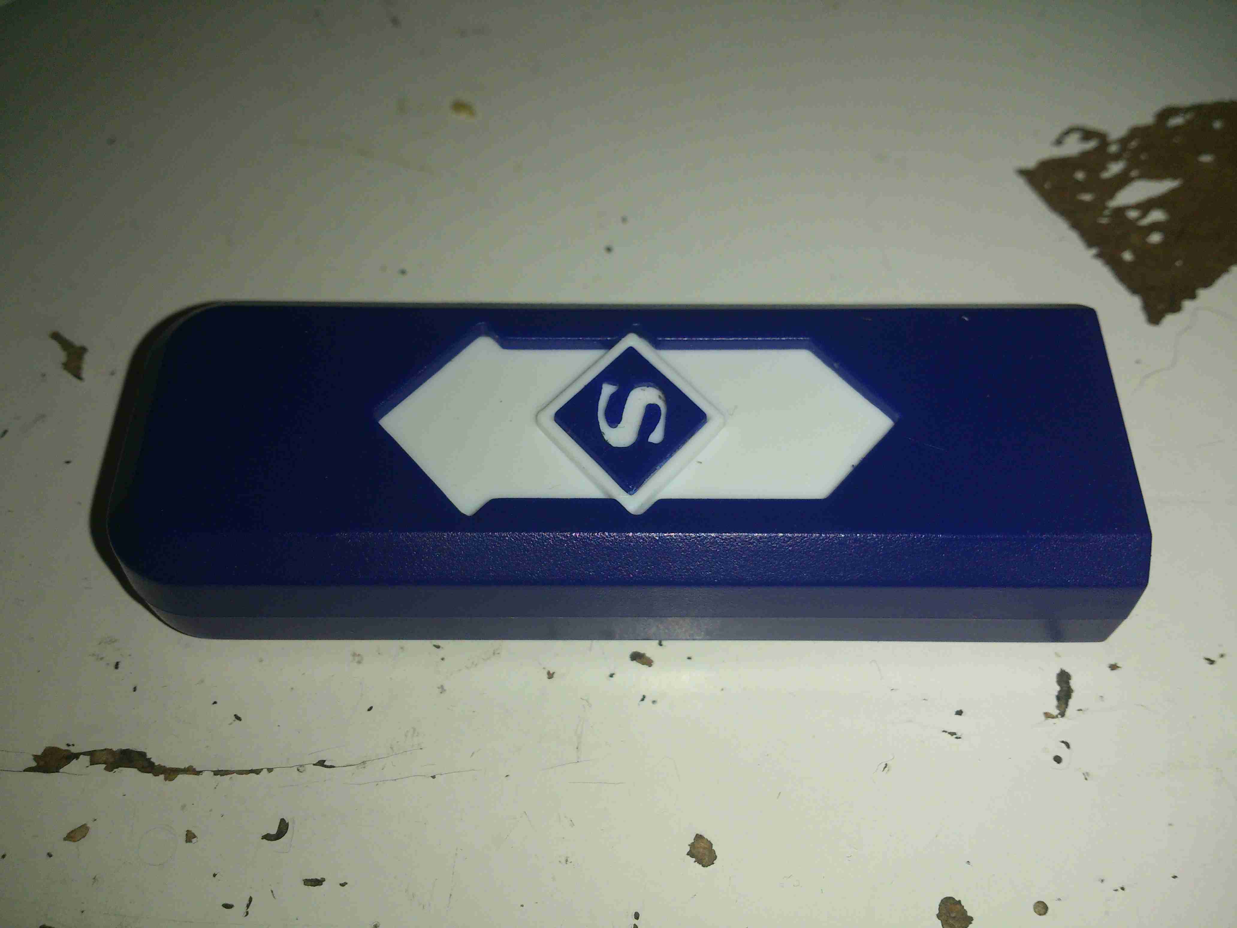
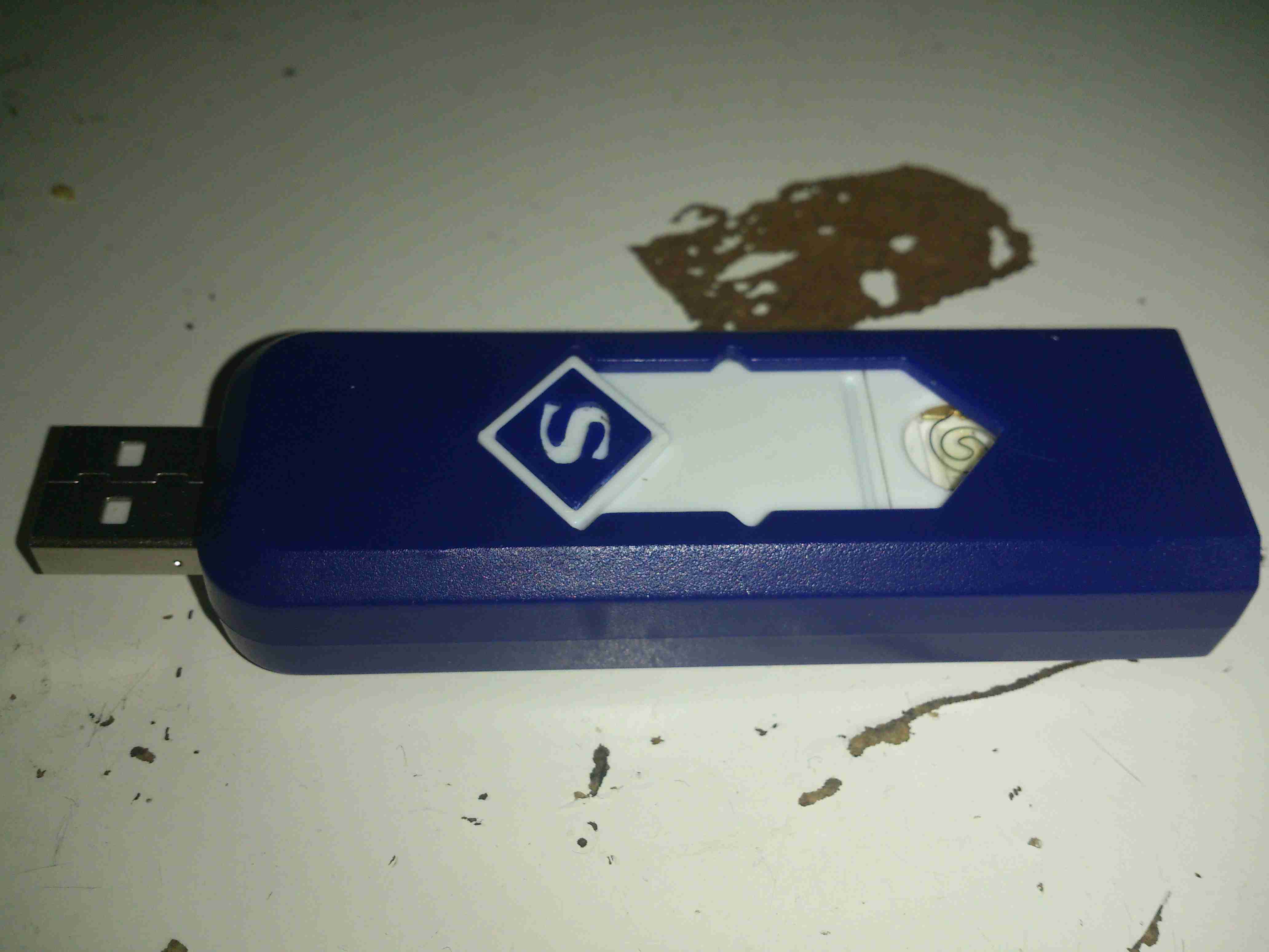
With a recent order from a Chinese seller on eBay, this little gadget was included in the package as a freebie:
Electronic Lighter
I’ve not smoked for a long time, so I’m not too sure what use I’m going to find for this device, but it’s an electronic lighter!
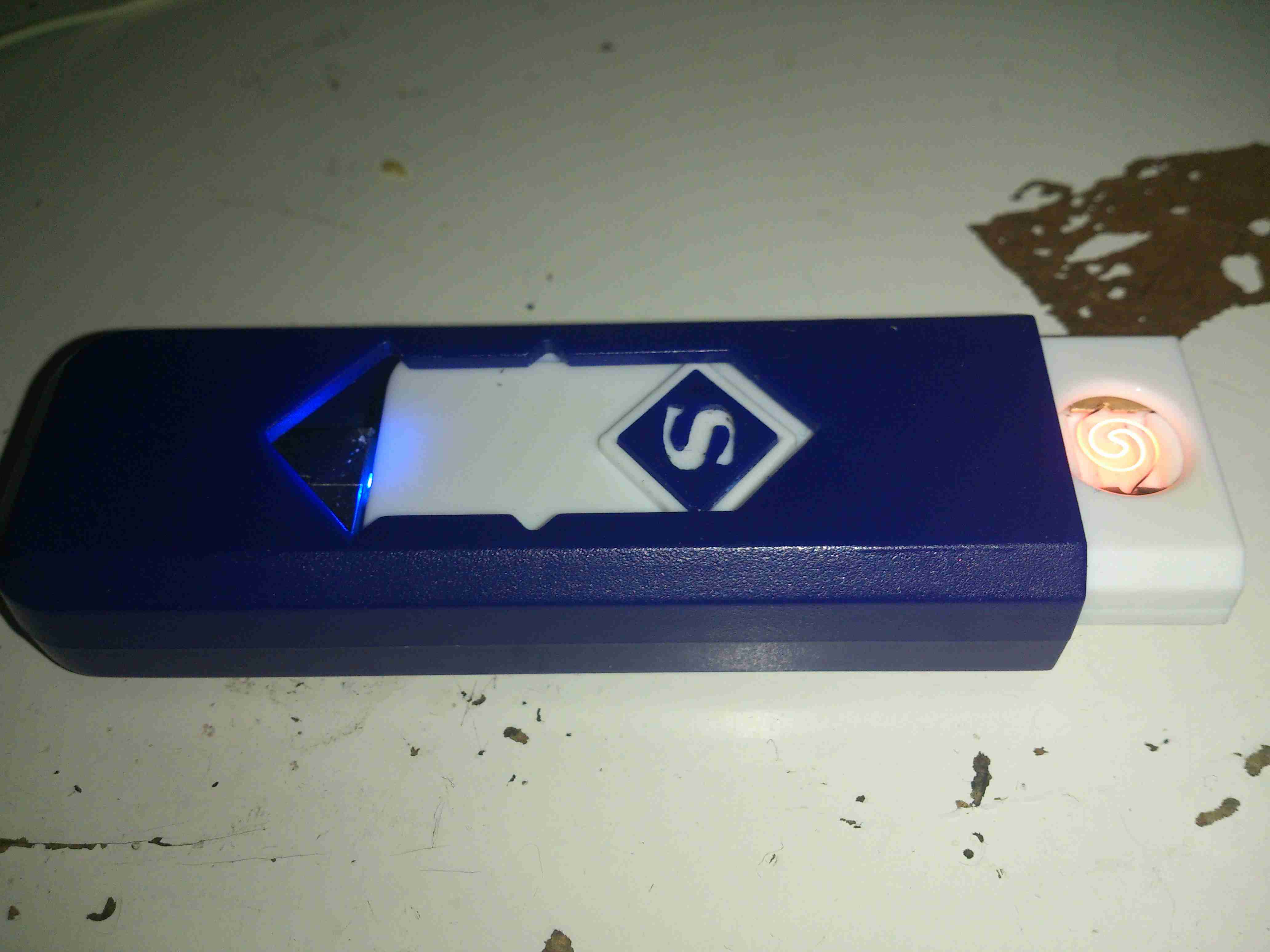
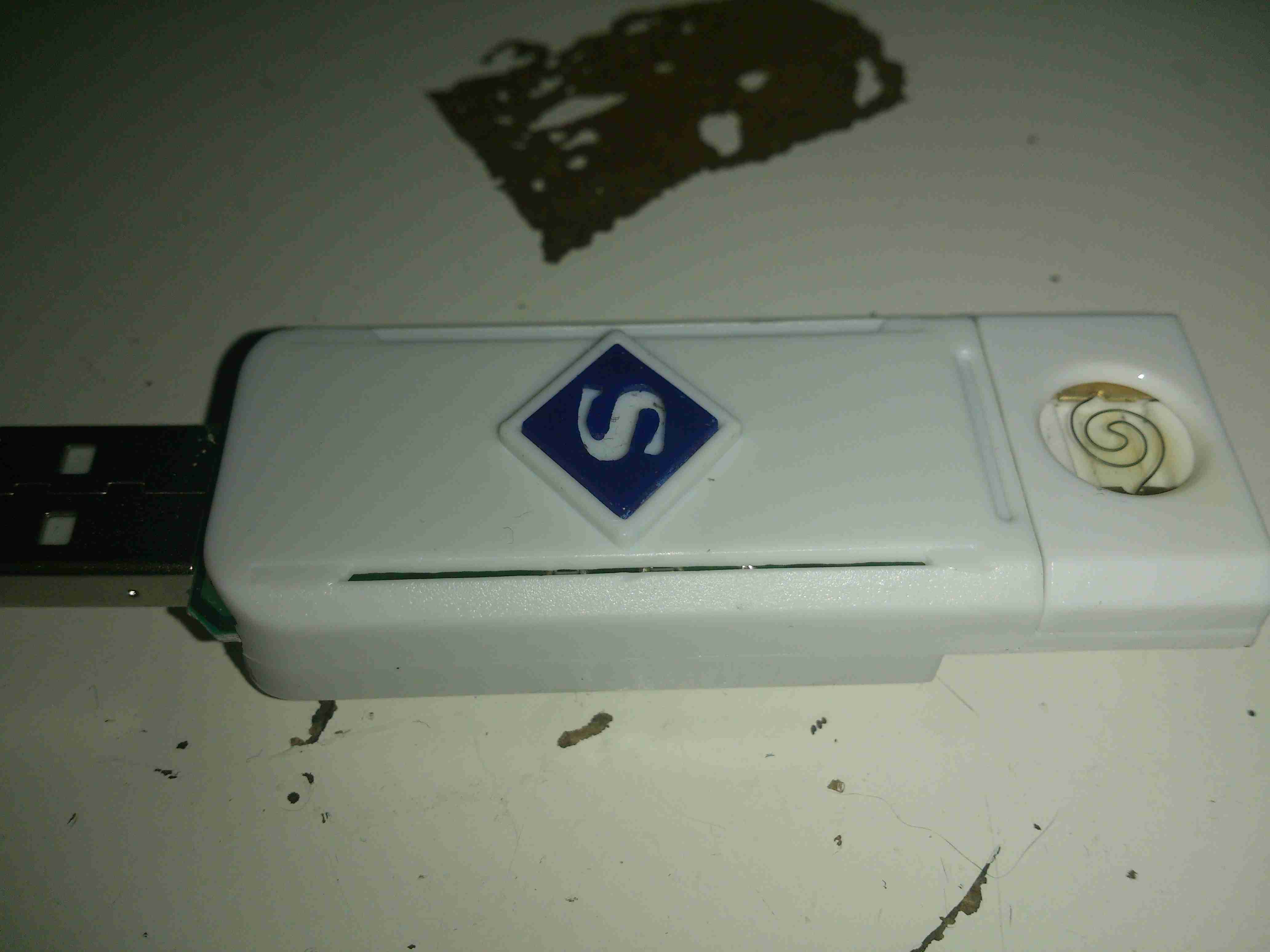
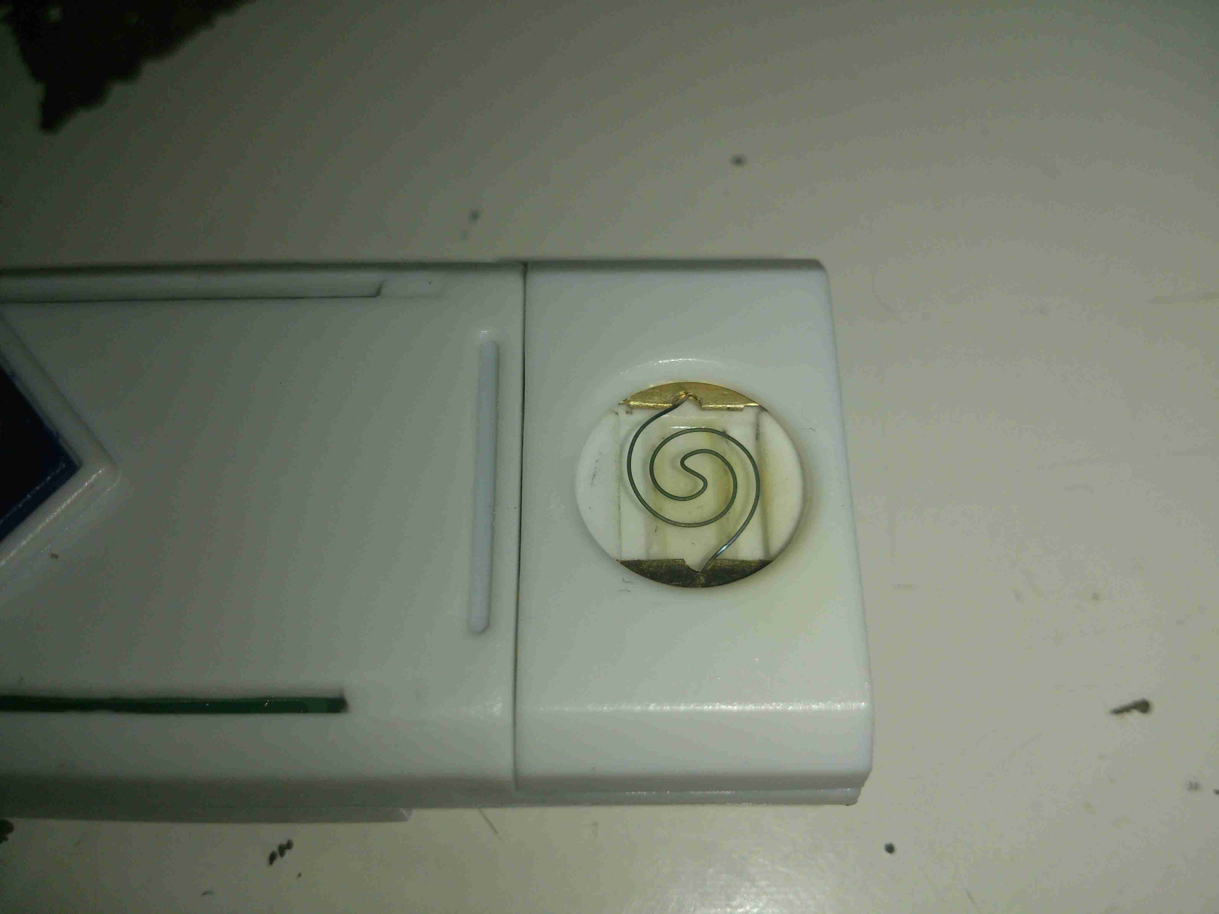
Pyromaniac Mode
Pushing the slider forward reveals a red-hot heater, mounted in the plastic (!) frame.
Charging Mode
Pushing the other way reveals a USB port to charge the internal battery.
Core Removed
A couple of screws releases the end cap from the cover & the entire core unit slides out. Like all Chinese toys it’s made of the cheapest plastic imaginable, not such a good thing when heat is involved.
Heating Element
The element itself is a simple coil of Nichrome wire, crimped to a pair of brass terminals. The base the heater & it’s terminals are mounted to is actually ceramic – the surround though that this ceramic pill clips into is just the same cheap plastic. Luckily, the element only remains on for a few seconds on each button push, there’s no way to keep it on & start an in-pocket fire, as far as I can see.
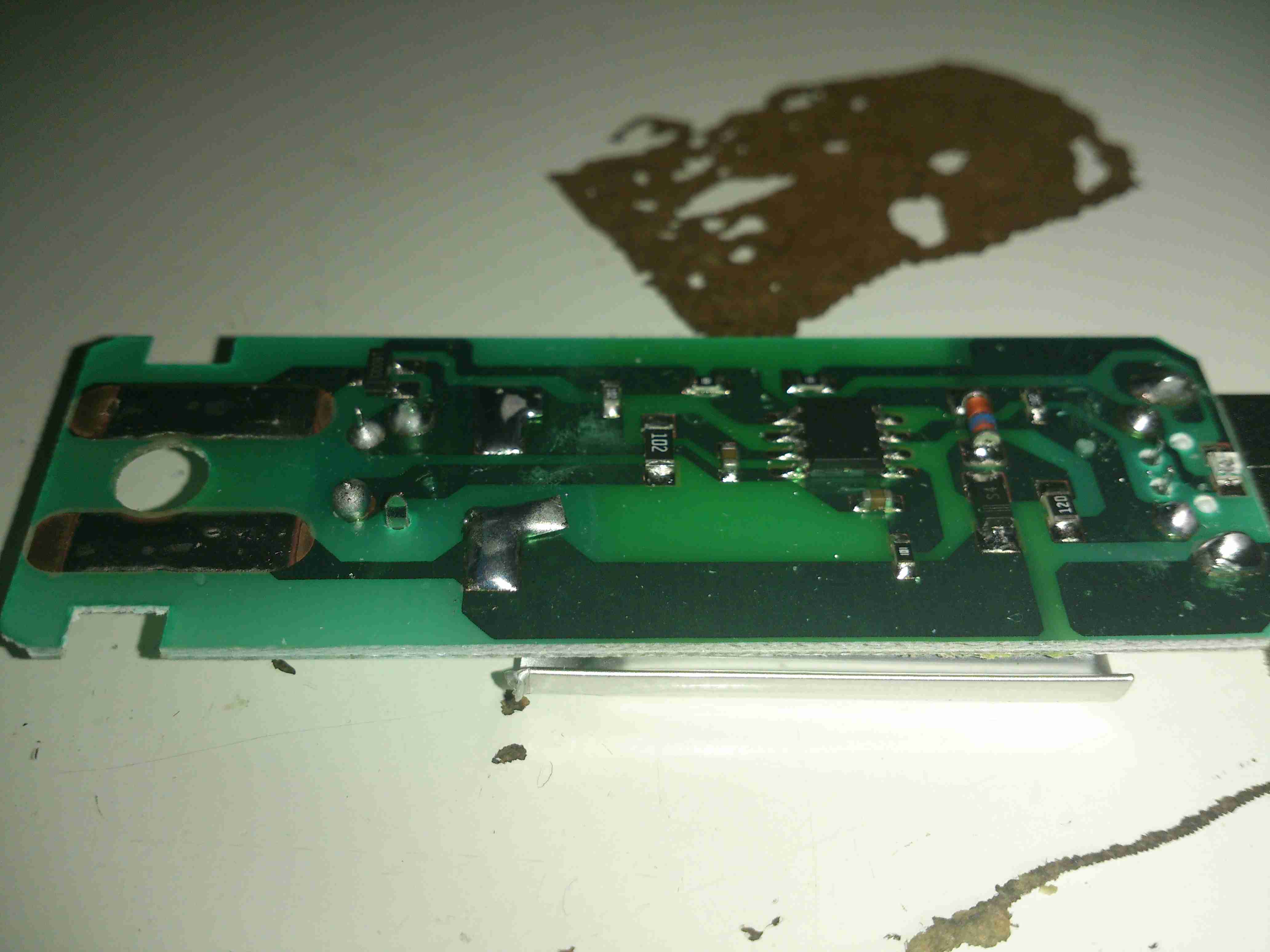
Main PCB
The main PCB clips out of the back of the core frame, the large pair of tinned pads on the left connect to the heater, the control IC has no numbering of any kind, but considering the behaviour of the device it’s most likely a standard eCig control IC.
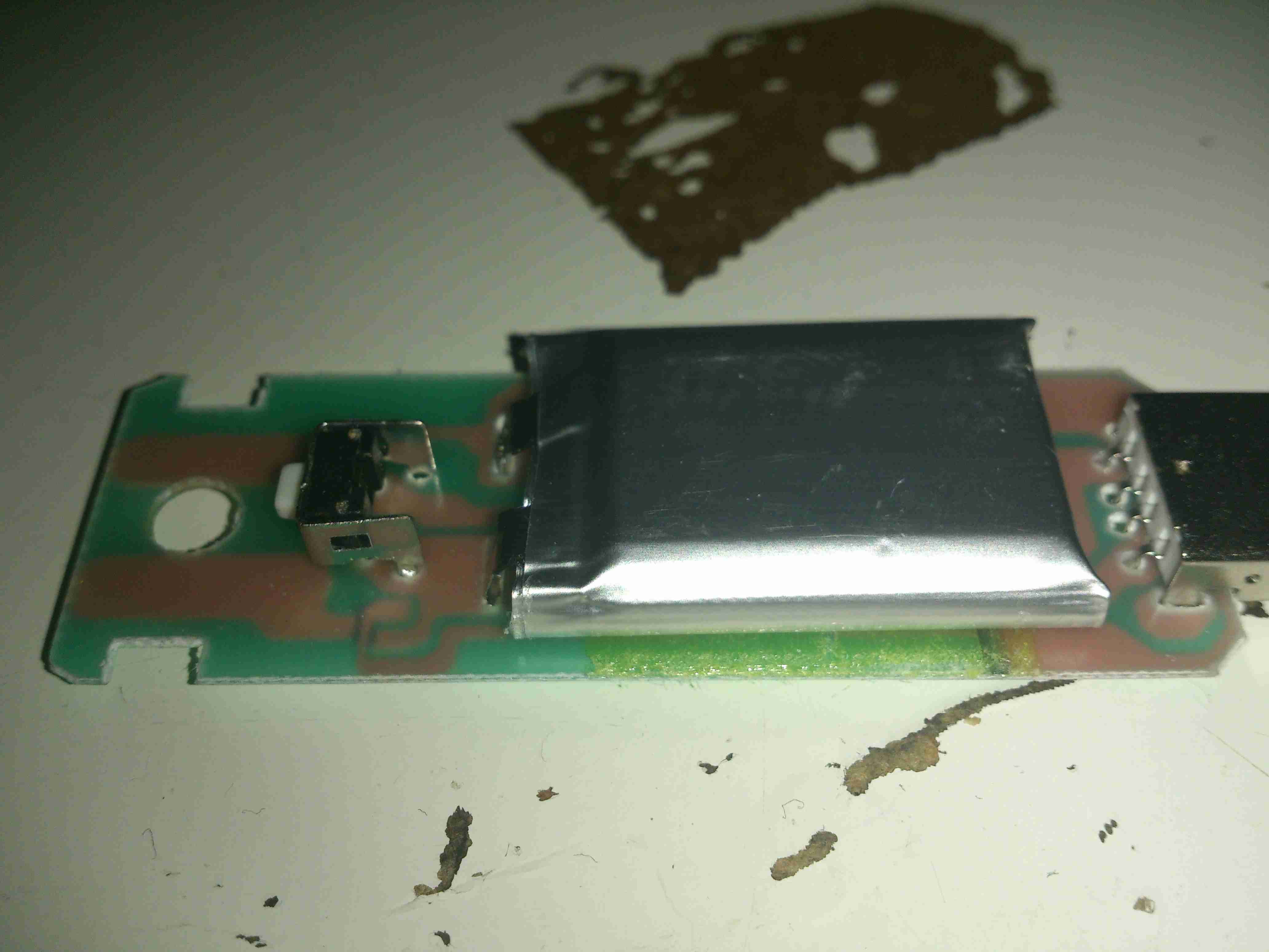
LiPo Cell
The other side of the board has the USB port on the right, the Lithium Polymer cell in the centre, and the power button on the left. The cell itself also has no marking, but I’m guessing a couple hundred mAh from the physical size.
In the past, I’ve used RC type LiPo packs for my mobile power requirements, but these tend to be a bit bulky, since they’re designed for very high discharge current capability – powering large motors in models is a heavy job.
I recently came across some Samsung Galaxy Tab 10.1 battery packs on eBay very cheaply, at £2.95 a piece. For this price I get 6800mAh of capacity at 4.2v, for my 12v requirements, 3 packs must be connected in series, for a total output of 12.6v fully charged.
For an initial pack, I got 9 of these units, to be connected in 3 sets of 3 to make 20Ah total capacity.There are no control electronics built into these batteries – it’s simply a pair of 3400mAh cells connected in parallel through internal polyfuses, and an ID EEPROM for the Tab to identify the battery.
This means I can just bring the cell connections together with the original PCB, without having to mess with the welded cell tabs.
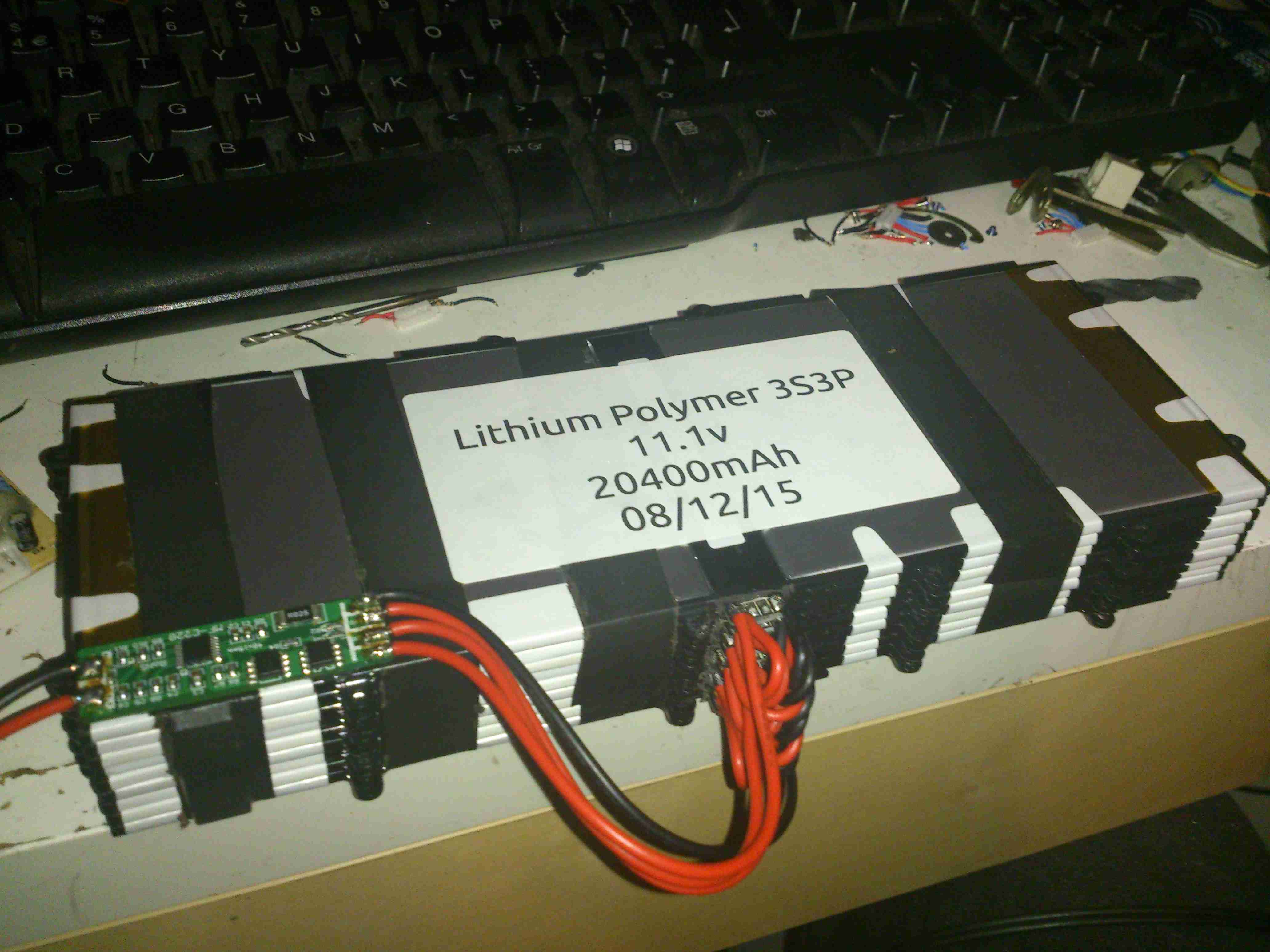
Battery Pack
Here’s the pack with it’s cell connections finished & a lithium BCM connected. This chemistry requires close control of voltages to remain stable, and with a pack this large, a thermal runaway would be catastrophic.
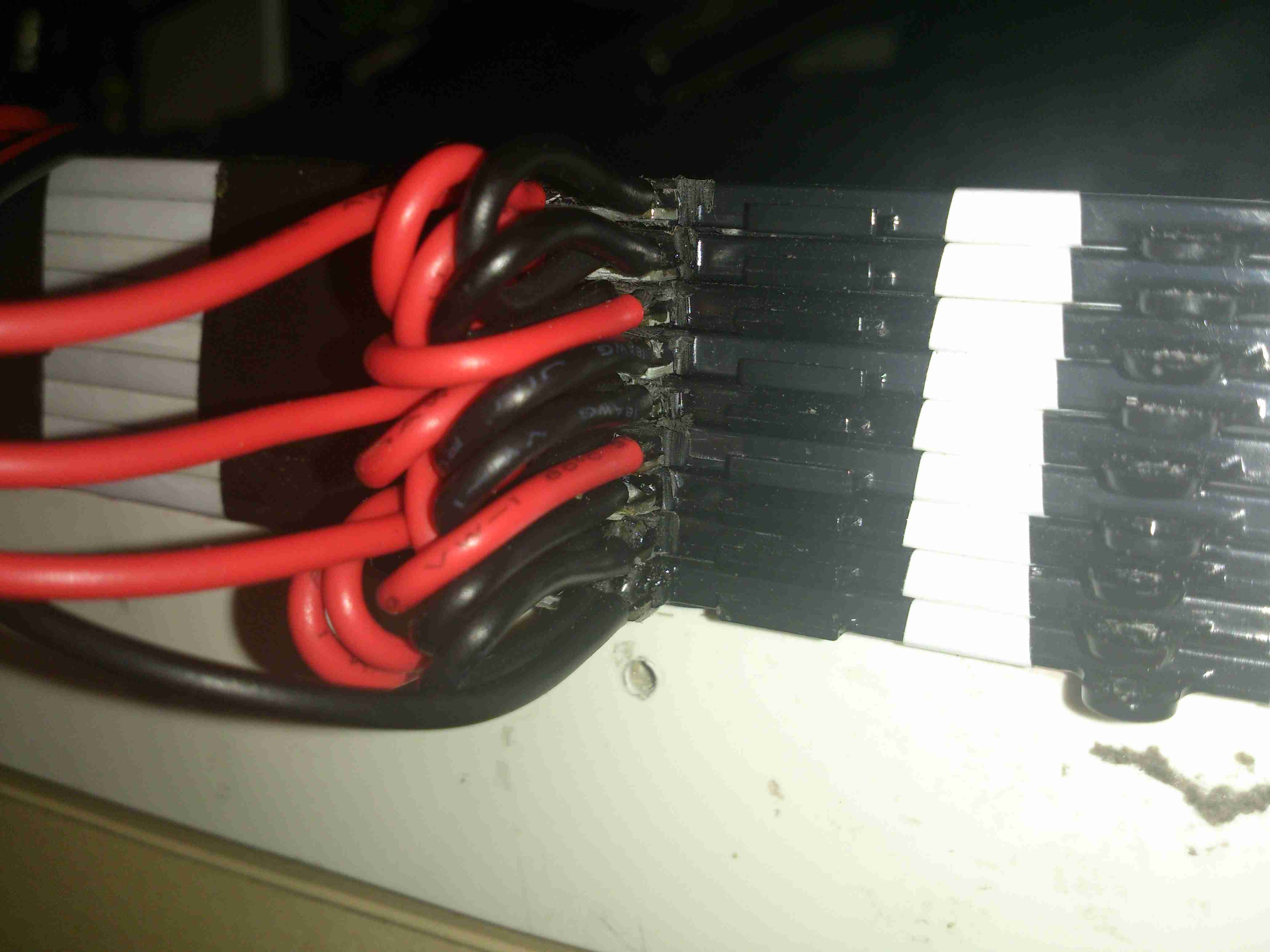
Cell Links
The OEM battery connector has been removed, and my series-parallel cell connections are soldered on, with extra lead-outs for balancing the pack. This was the most time-consuming part of the build.
If all goes well with the life of this pack for utility use, I’ll be building another 5 of these, for a total capacity of 120Ah. This will be extremely useful for portable use, as the weight is about half that of an equivalent lead-acid.
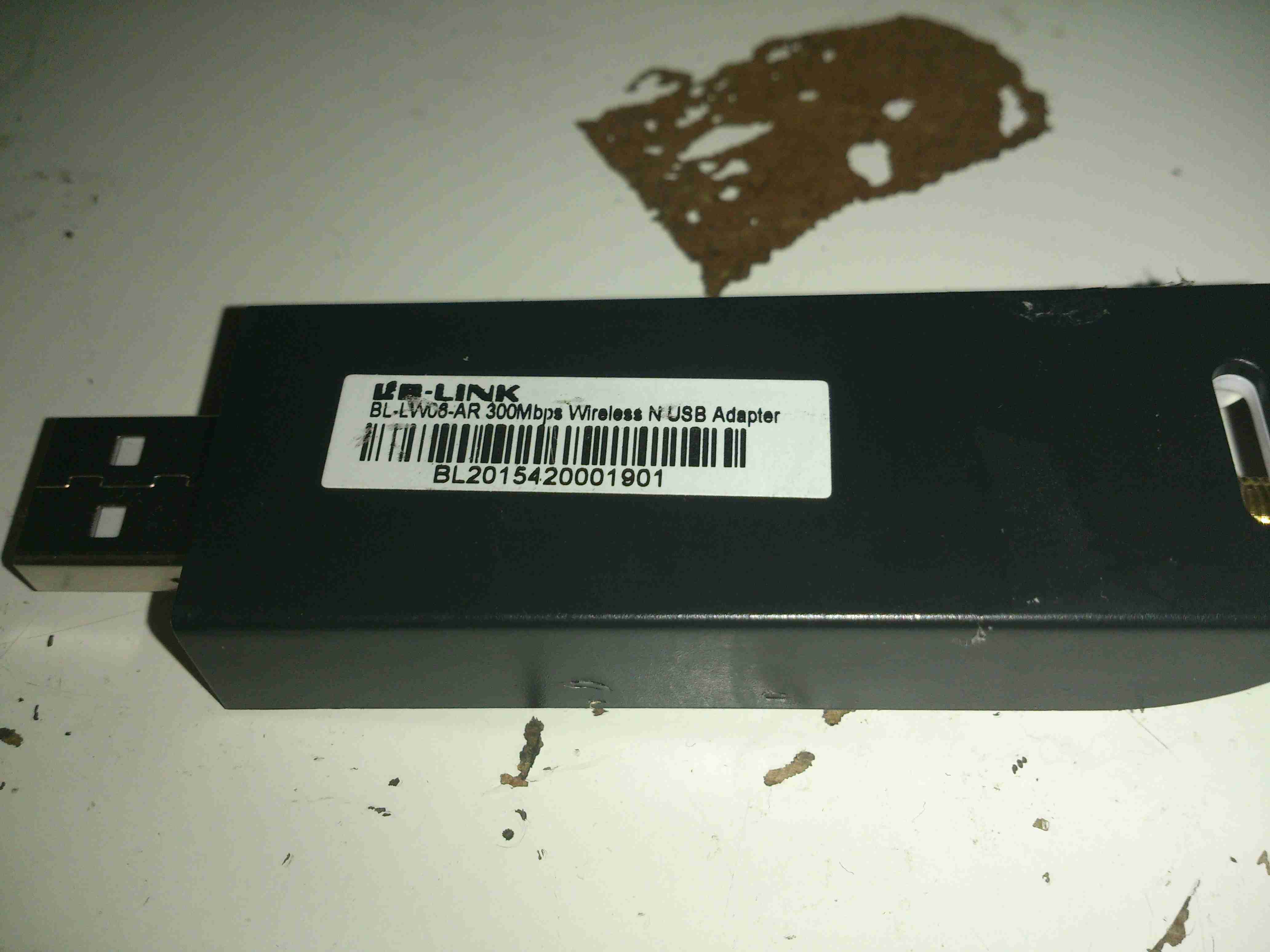
I needed a decent WiFi adaptor for my latest Pi LCD project, so after trawling eBay for cheapy USB adaptors, I found this one.
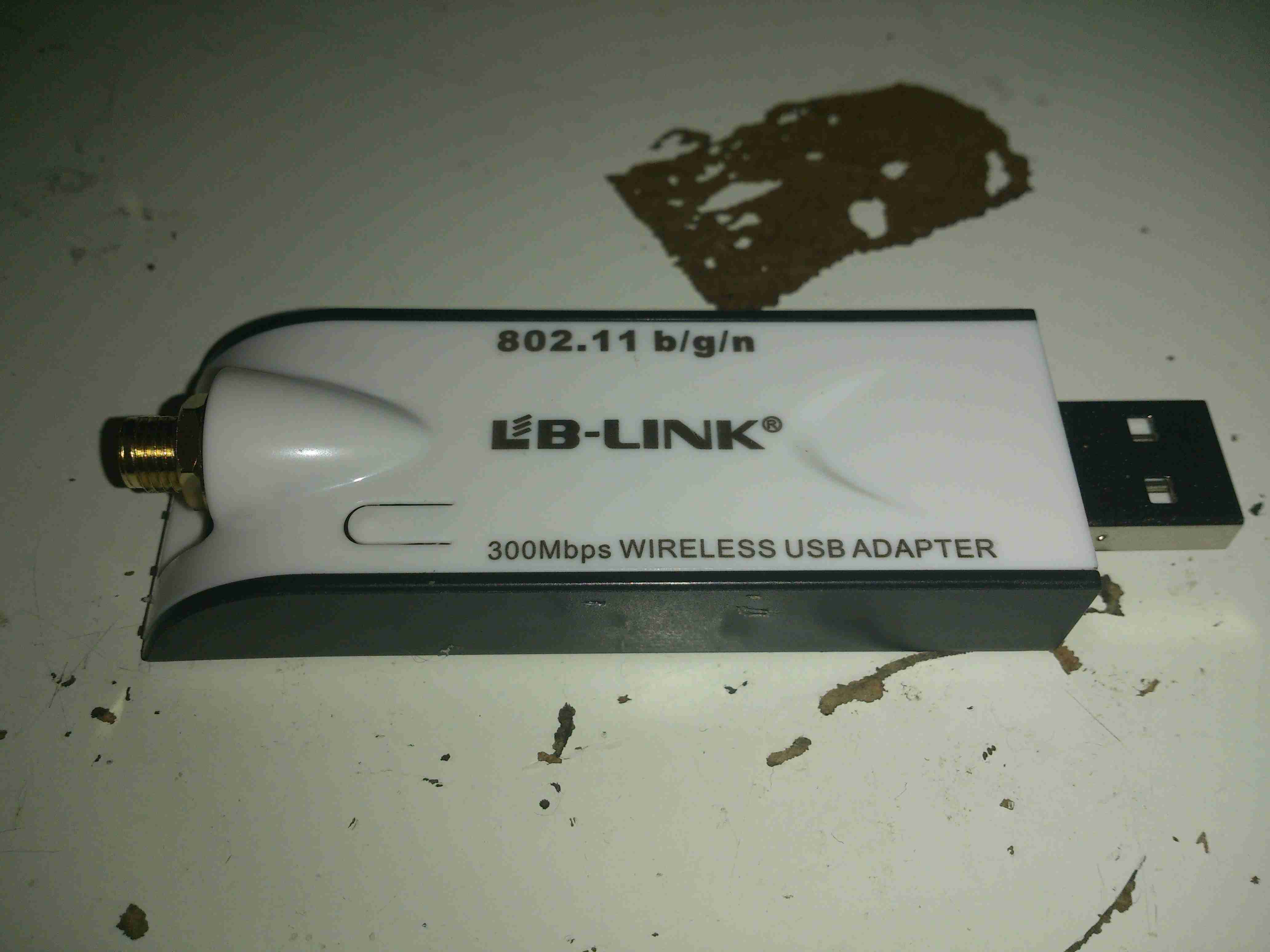
USB WiFi Dongle
Unlike most USB WiFi radios these days, it actually has a proper RP-SMA antenna connector, not the low-gain built in jobbies that never seem to work too well.
There are a few versions of this adaptor, all of which seem to use the same casing, there’s a button push cut into the plastic for a WPS button that doesn’t exist on this model. This is fine, as I don’t enable WPS on any of my network equipment anyway. (It’s insecure, and can be cracked in minutes).
MAC Address
Here’s the rest of the essential details, the model is BL-LW08-AR, rated at 300Mbit/s.
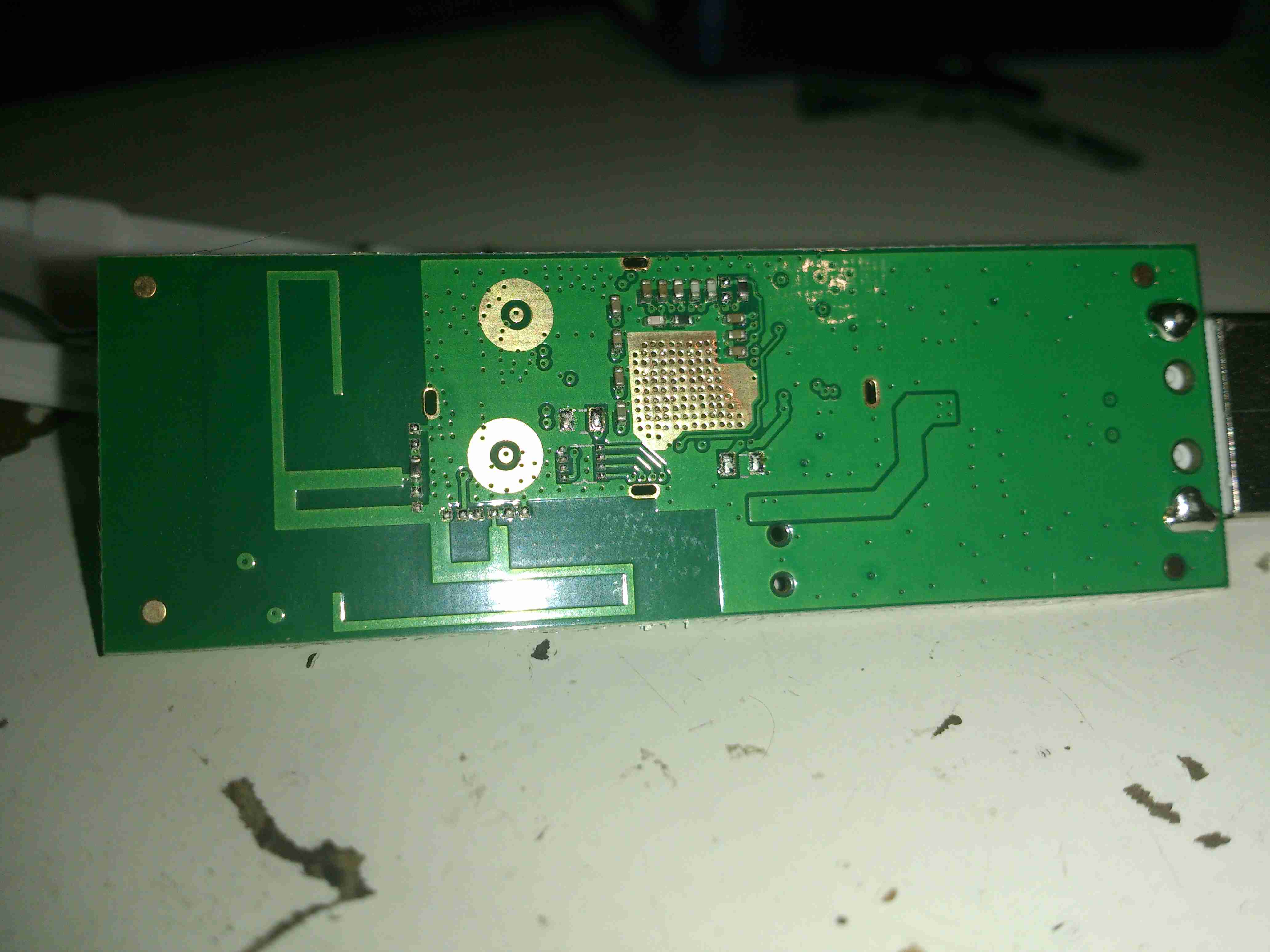
PCB Reverse
Here’s the PCB removed from the casing, there are a pair of PCB antennas on here, but they’re not connected to the RF circuitry in this model, the links are missing.
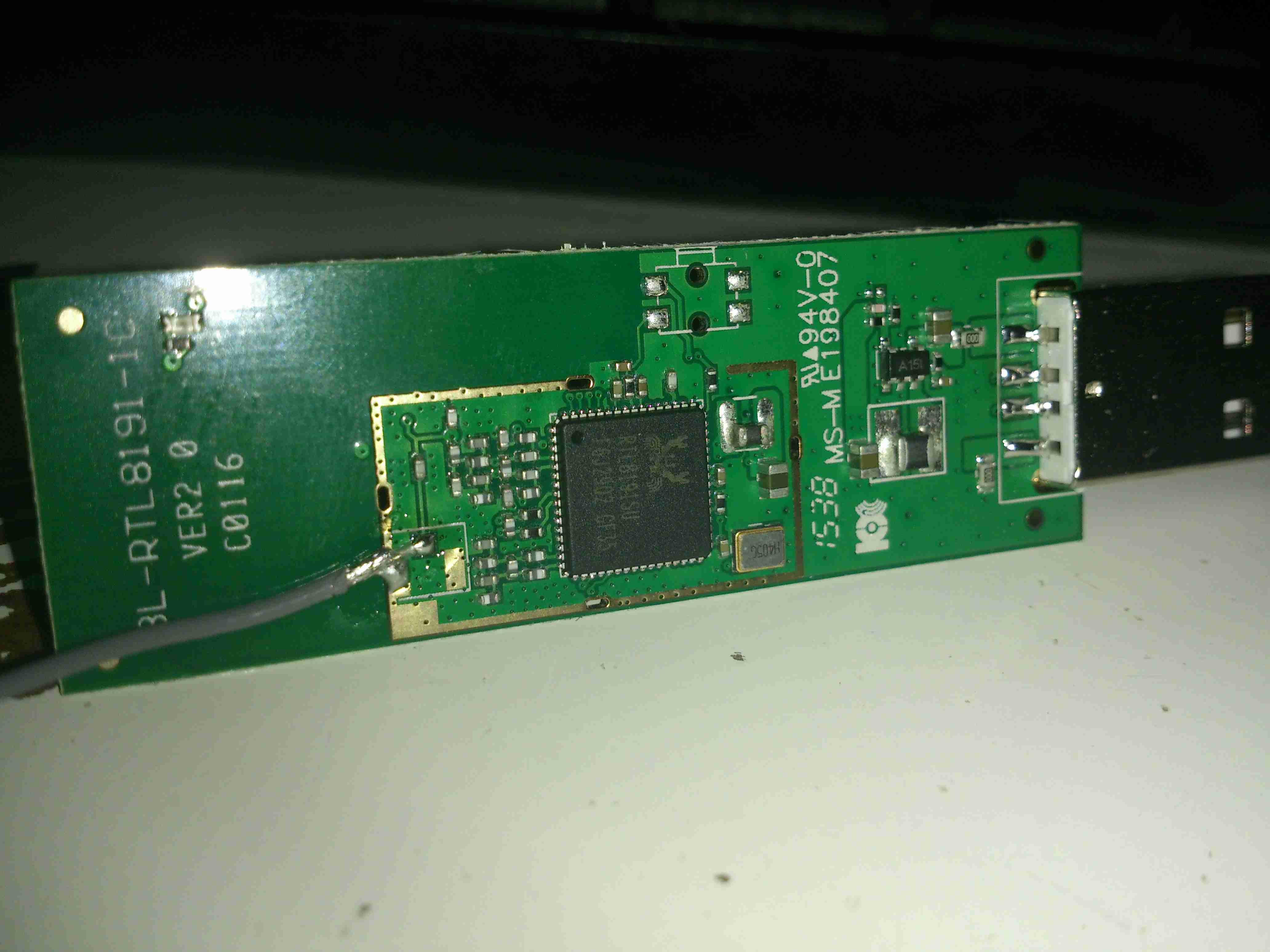
Chipset
The chipset used is a Realtek RTL8191SU, there isn’t much more in this device, as it’s all built into the silicon.
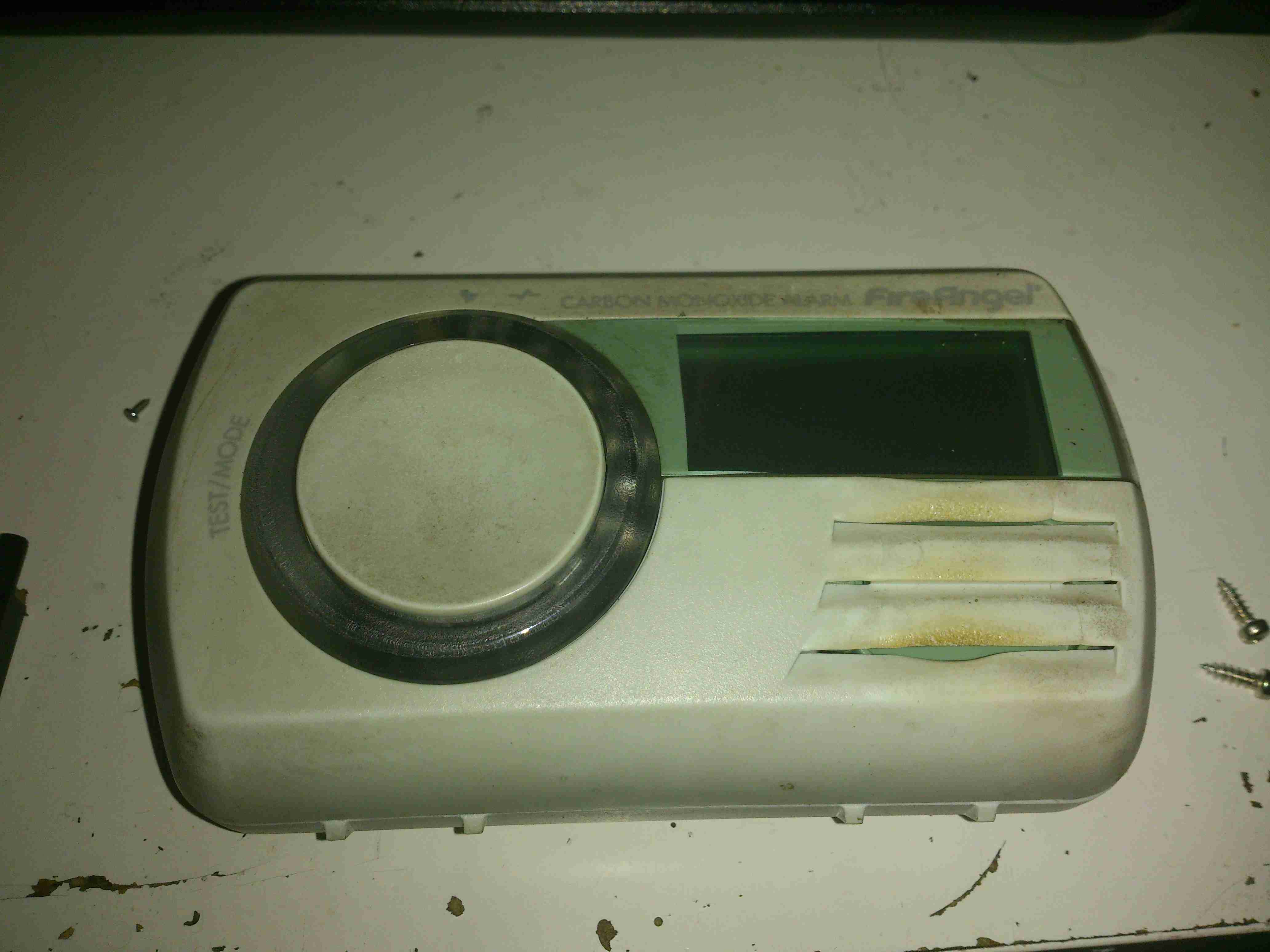
This detector has now been retired from service since it’s a fair bit out of date. So here’s the teardown!
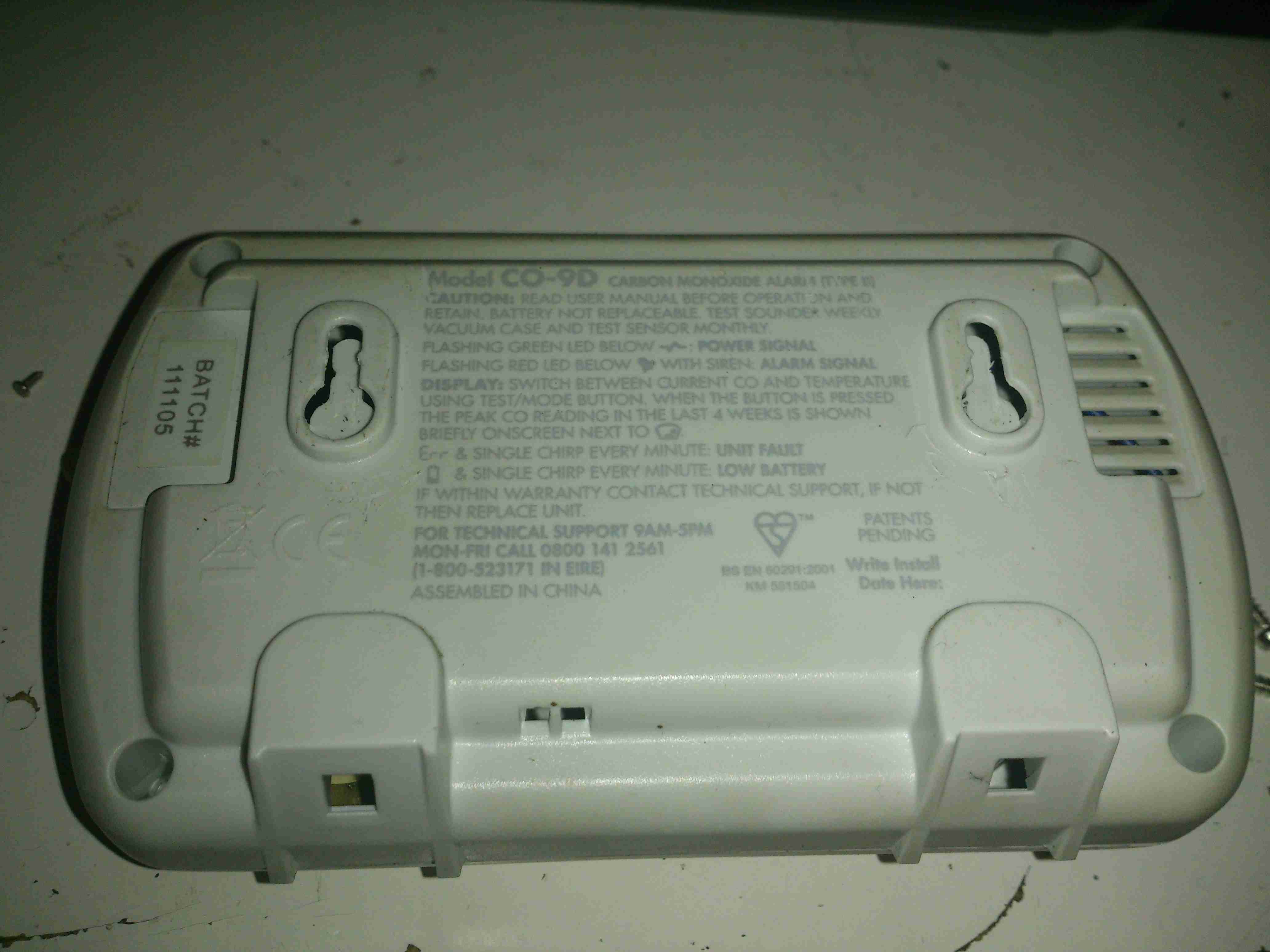
Information
Unlike older detectors, this unit has a built in battery that never needs replacing during the life of the sensor, so once the unit reaches it’s expiry date it’s just trashed as a whole.
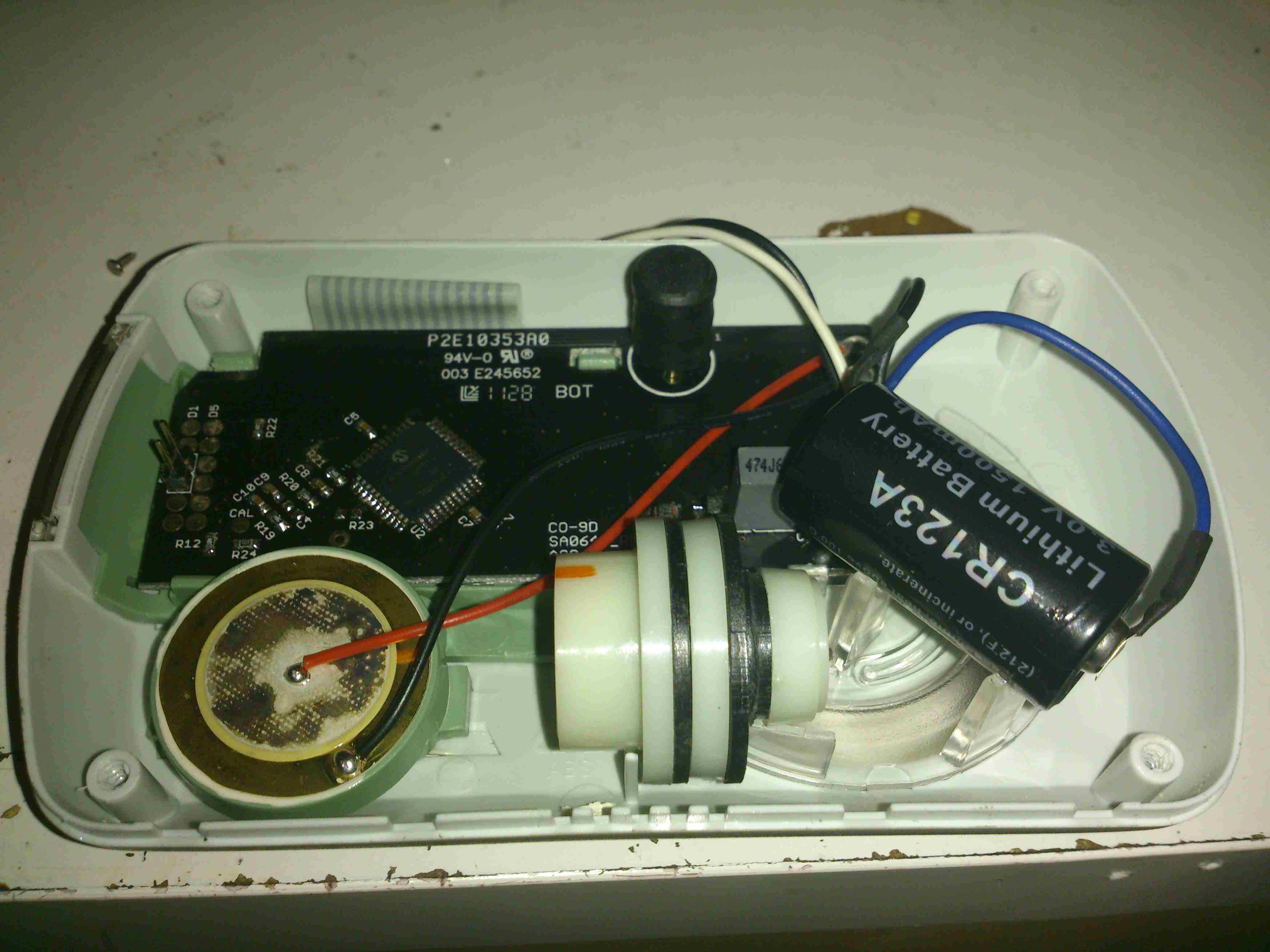
Cover Removed
4 screws hold the cover on, here’s the internals of the detector. There’s a 3v CR123A LiMnO² cell at the right for power, rated at 1500mAh. A 7 year life is quite remarkable on a single cell!
The sensor is just to the left of the lithium cell, and is of quite unusual construction. Previous CO sensor cells I’ve seen have been small cylinders with a pair of brass pins. This one appears to use a conductive plastic as the connections. These sensors contain H²SO⁴ so they’re a bit hazardous to open.
There are no manufacturer markings on the sensor & I’ve not been able to find any similarly shaped devices, so I’m unsure of it’s specifications.
The alarm sounder is on the left, the usual Piezo disc with a resonator to increase the loudness.
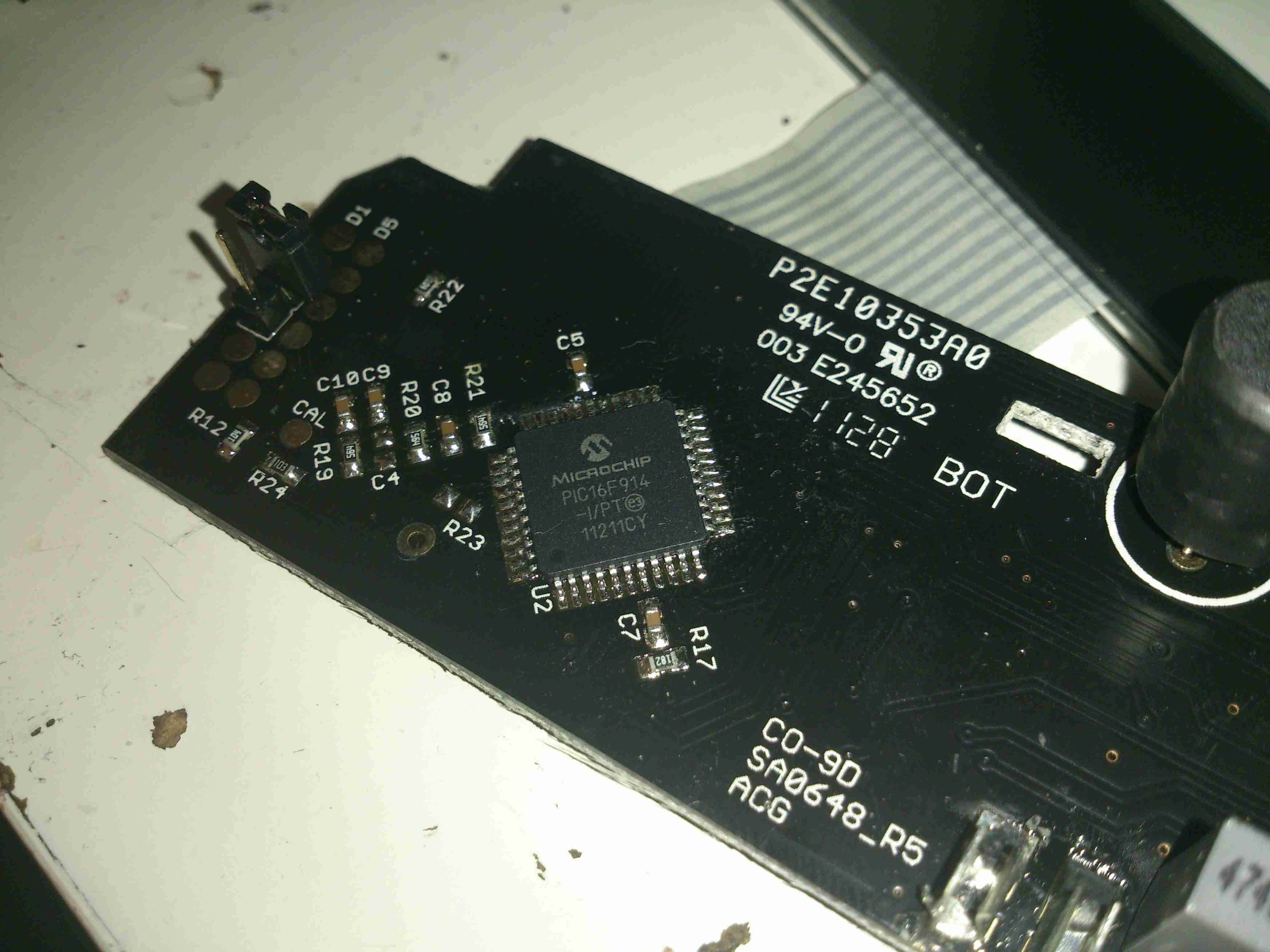
Microcontroller
The brains of the device are provided by a Microchip PIC16F914 microcontroller. This is a fairly advanced device, with many onboard features, and NanoWatt™ technology, standby power consumption is <100nA according to Microchip’s Datasheet. This would explain the incredible battery life.
The choke just at the right edge of the photo is actually a transformer to drive the Piezo sounder at high voltage.
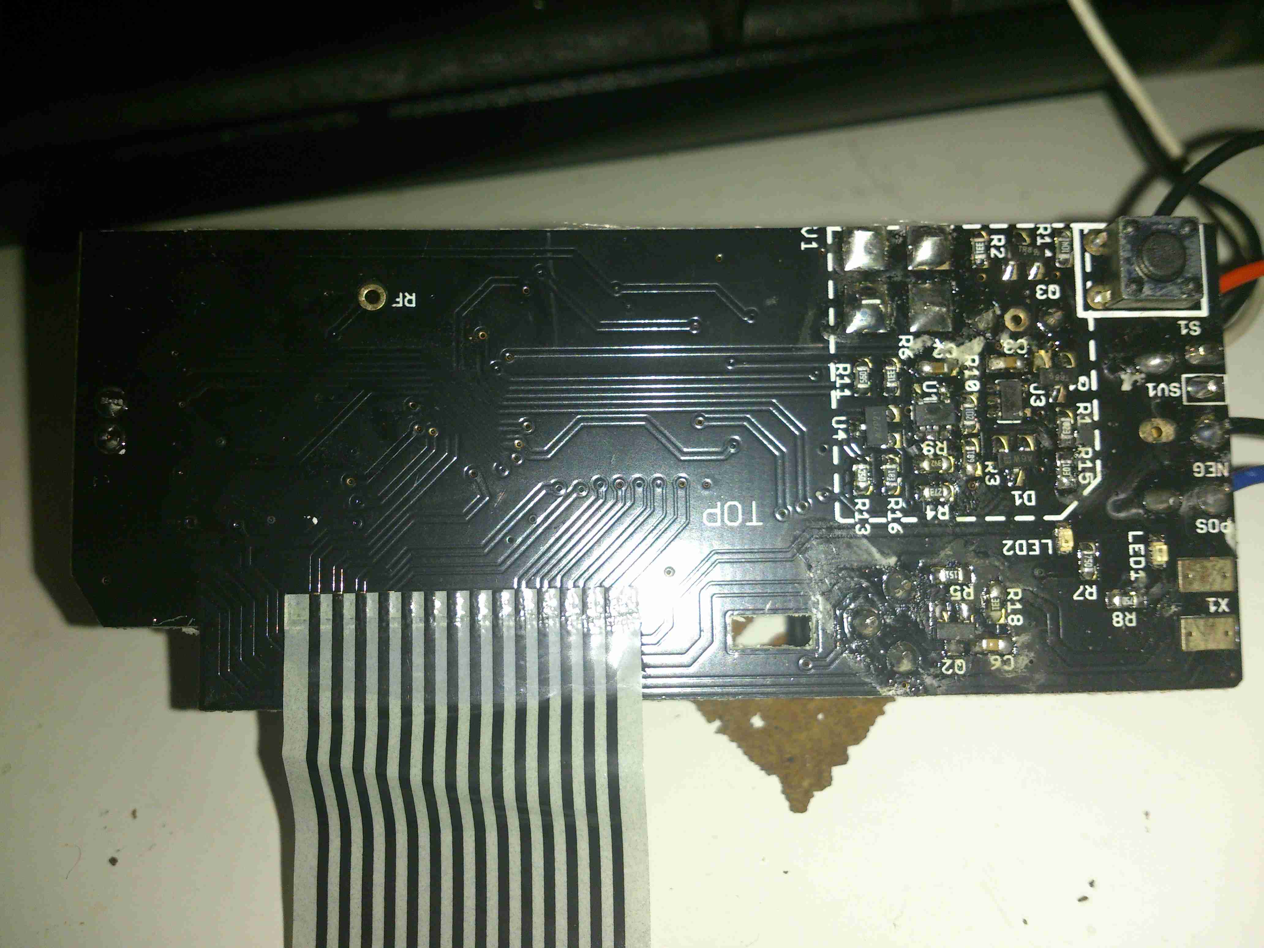
PCB Reverse
Here’s the PCB with the LCD frame removed. Not much to see on the this side, the silence/test button top right & the front end for the sensor.
Sensor Front End Amplifier
Here’s a closer look at the front end for the CO sensor cell itself. I haven’t been able to decode the SMT markings on the SOT packages, but I’m guessing that there’s a pair of OpAmps & a voltage reference.
Compressed air is a rather useful power source, especially when all maintenance is done by the on board crew instead of by boatyards.
Screwfix had a good deal on a 50L 3.5CFM air compressor, to save space this has been permanently mounted in a free space & air will be piped to where it is needed from a central point.
Because of the total height of the machine, the compressor itself has been unbolted from the tank, a copper line connecting the two back together at a larger distance.
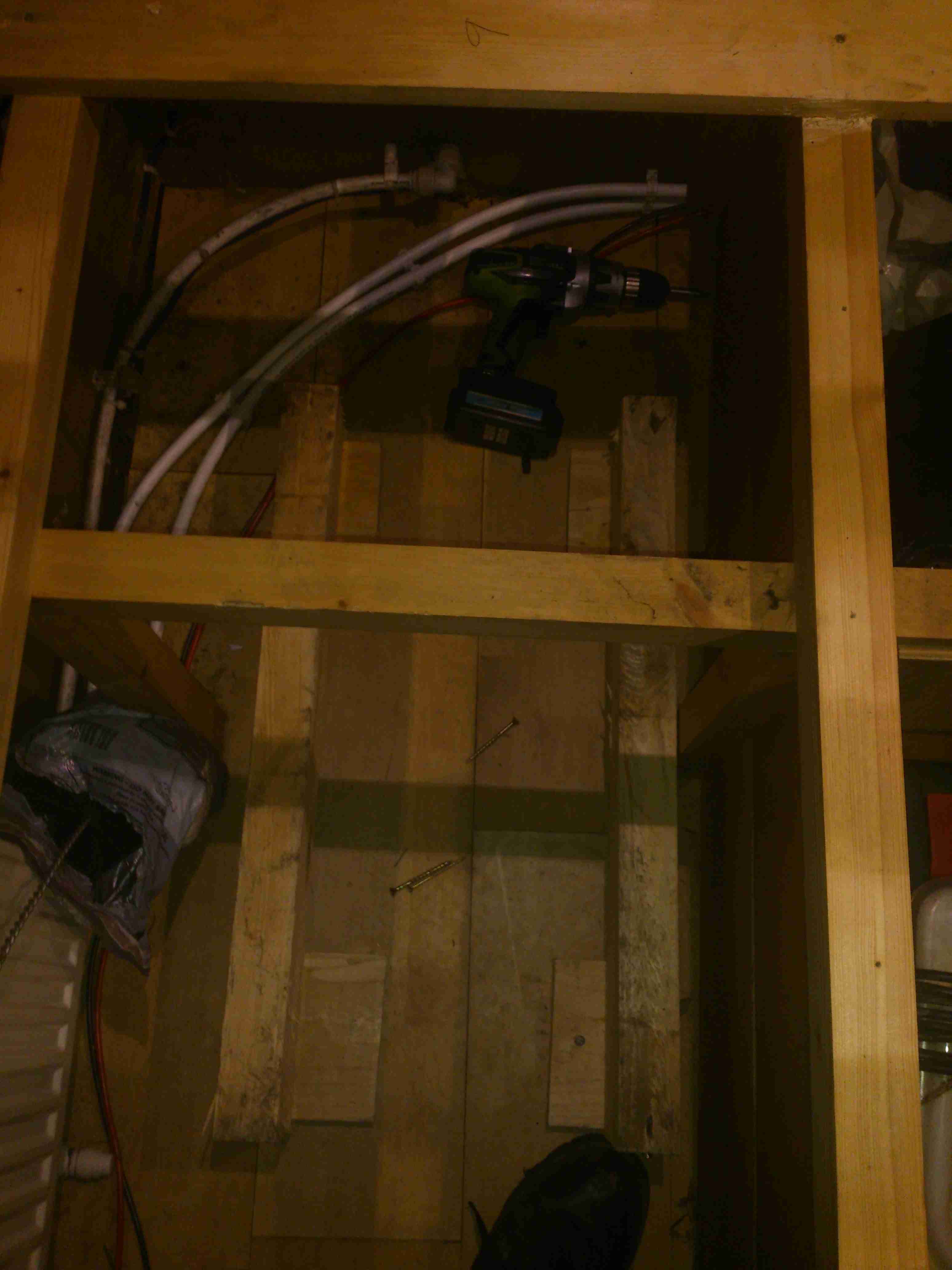
Bearers
In one of the very few free spaces available, under a bunk. A pair of timbers has been screwed to the floor to support the tank.
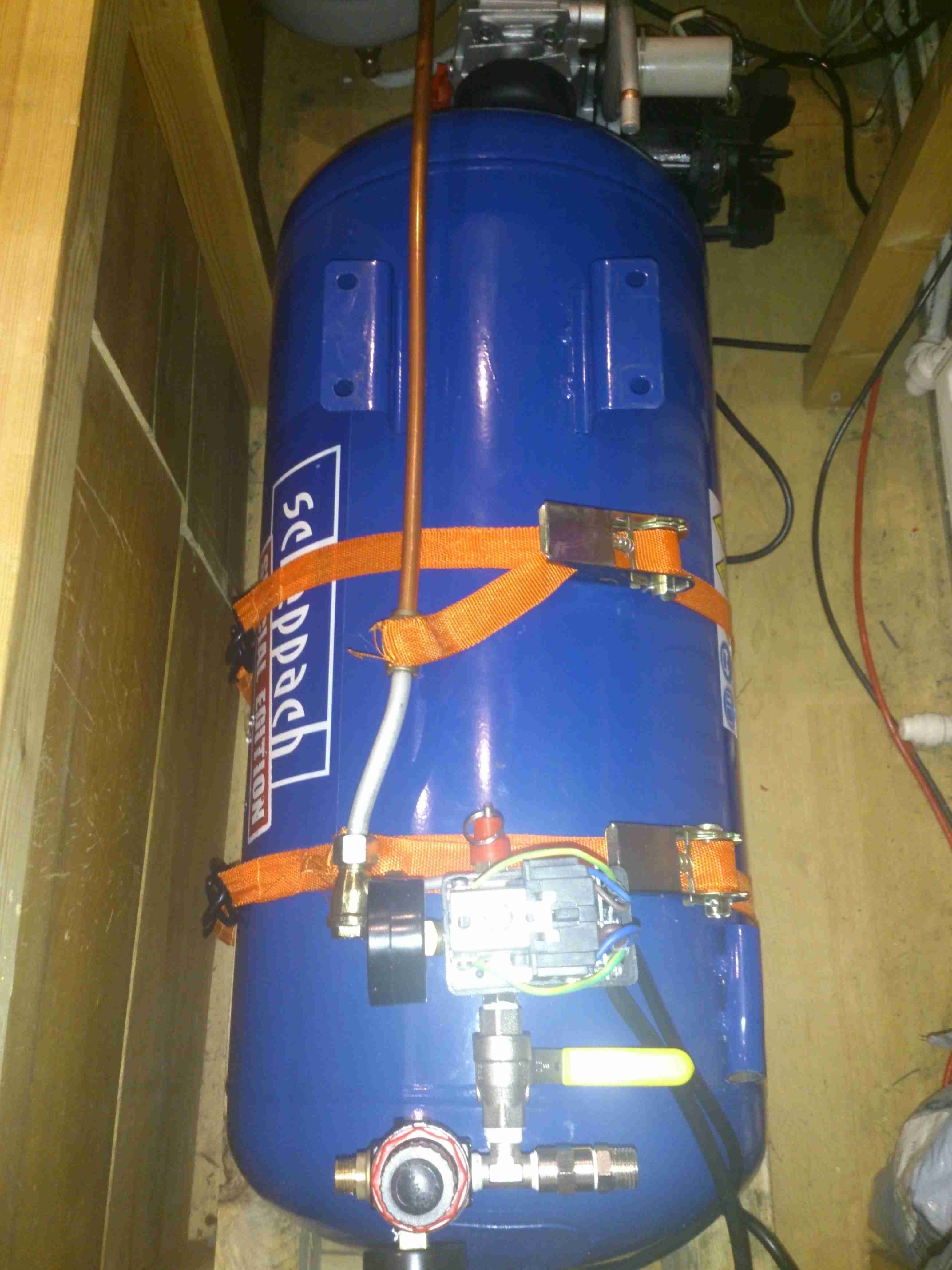
Tank Installed
The tank is strapped to the wooden supports with a pair of ratchet straps, the compressor itself can be seen just behind the tank. The copper line on the top of the tank is going back to be connected to the compressor outlet.
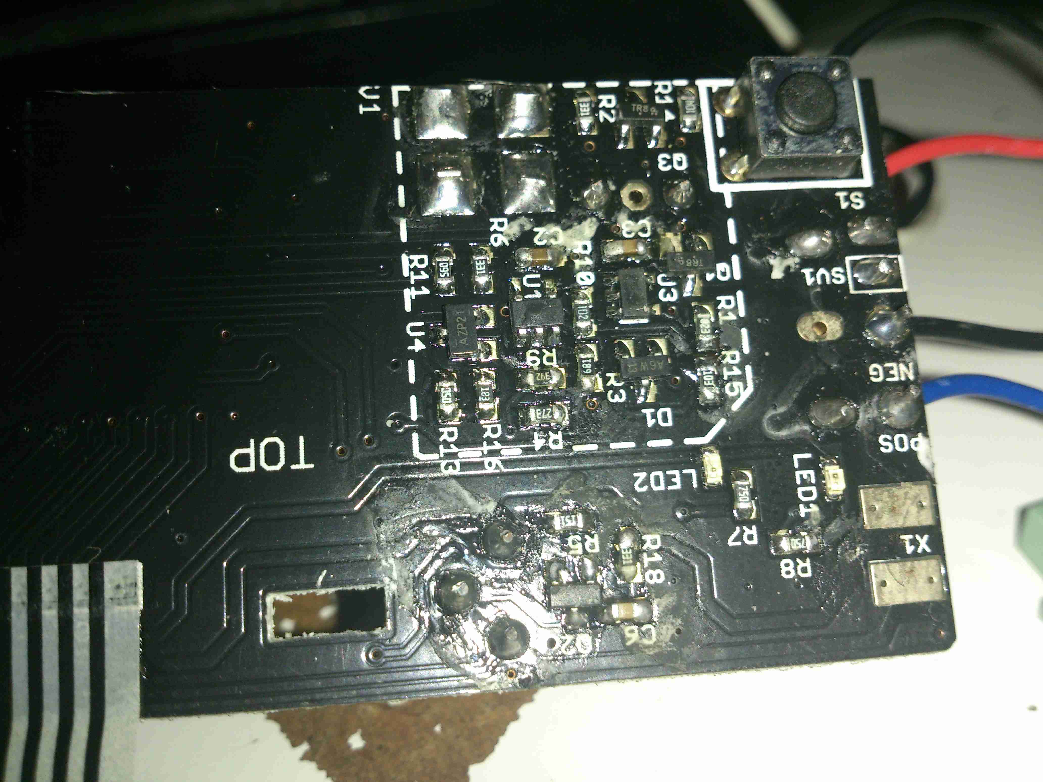
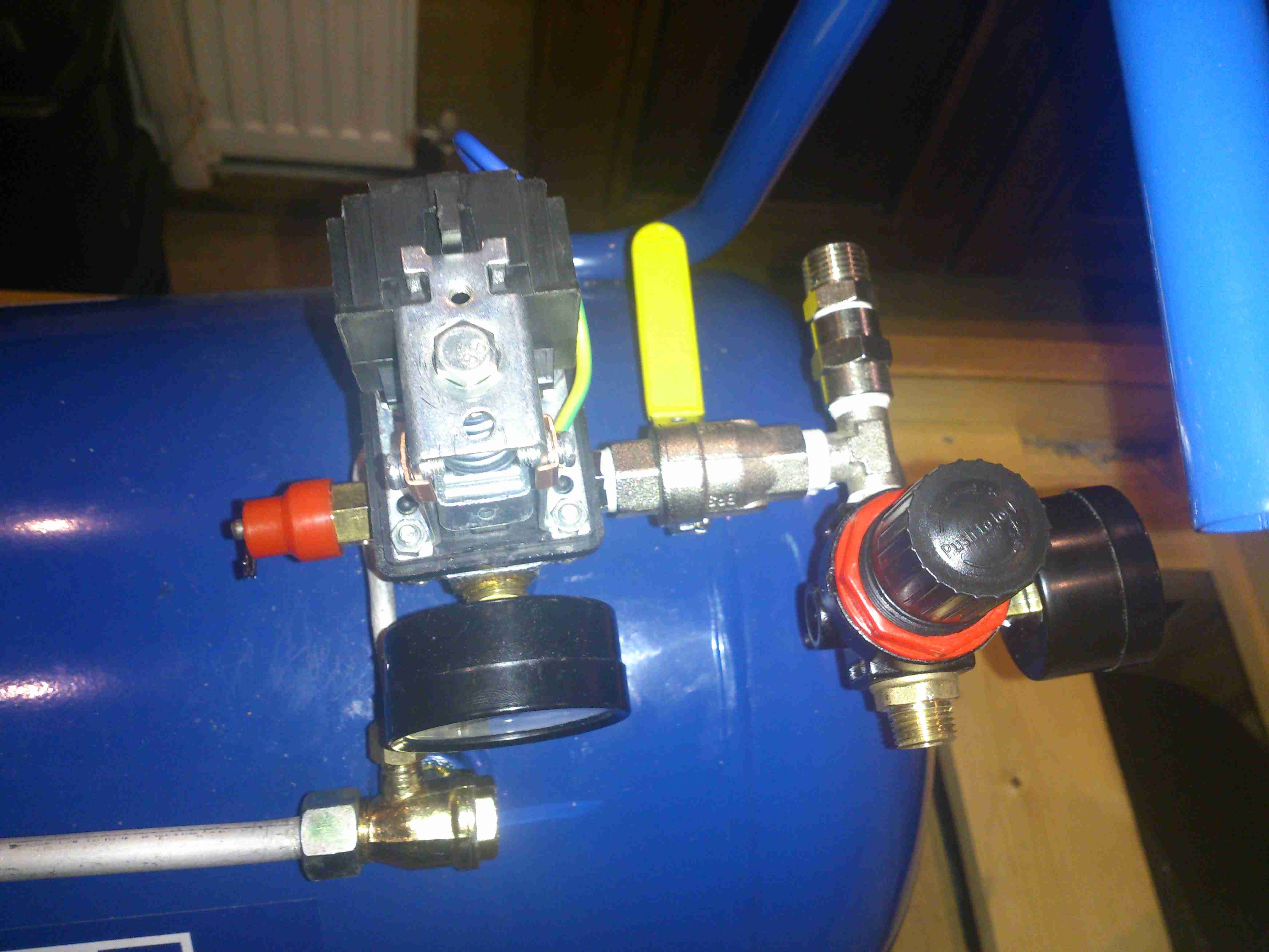
Air Fittings
Compressor control remains on top of the tank, the pressure switch & relief valve centre. After an isolation valve, the feed splits, the regulator installed will be feeding the air horn with 20PSI, replacing the existing automotive-style 12v air pump. The currently open fitting will be routed to a quick connect on the bulkhead. This will be accessible from the front deck, an air hose can be fitted to get a supply anywhere on board.
More to come when the rest of the system gets installed!
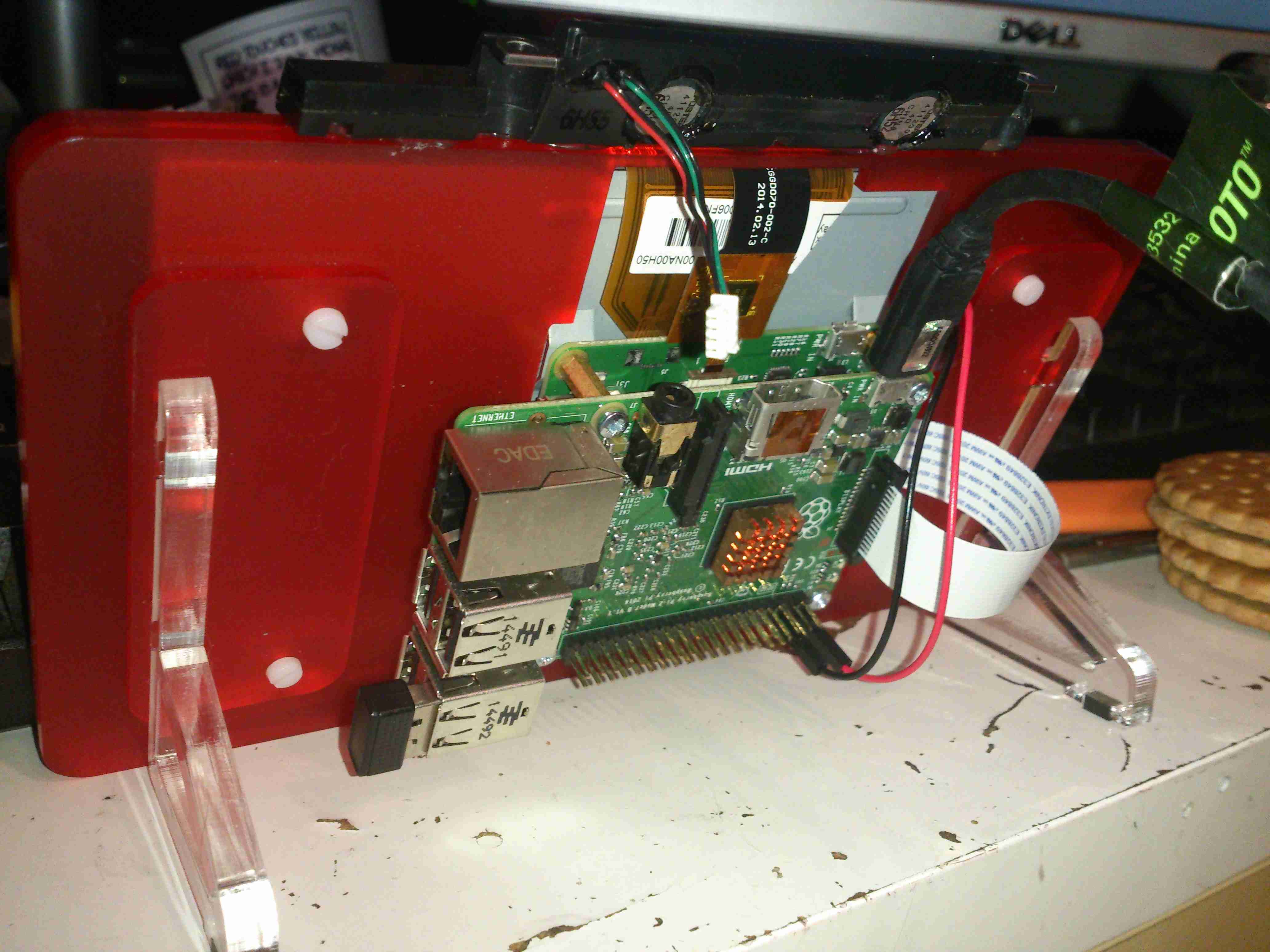
Finally the Raspberry Pi Foundation have released an official LCD for the DSI connector on the Pi. When these were announced, I placed an order straight away, but due to demand it’s taken quite a while for it to arrive in the post.
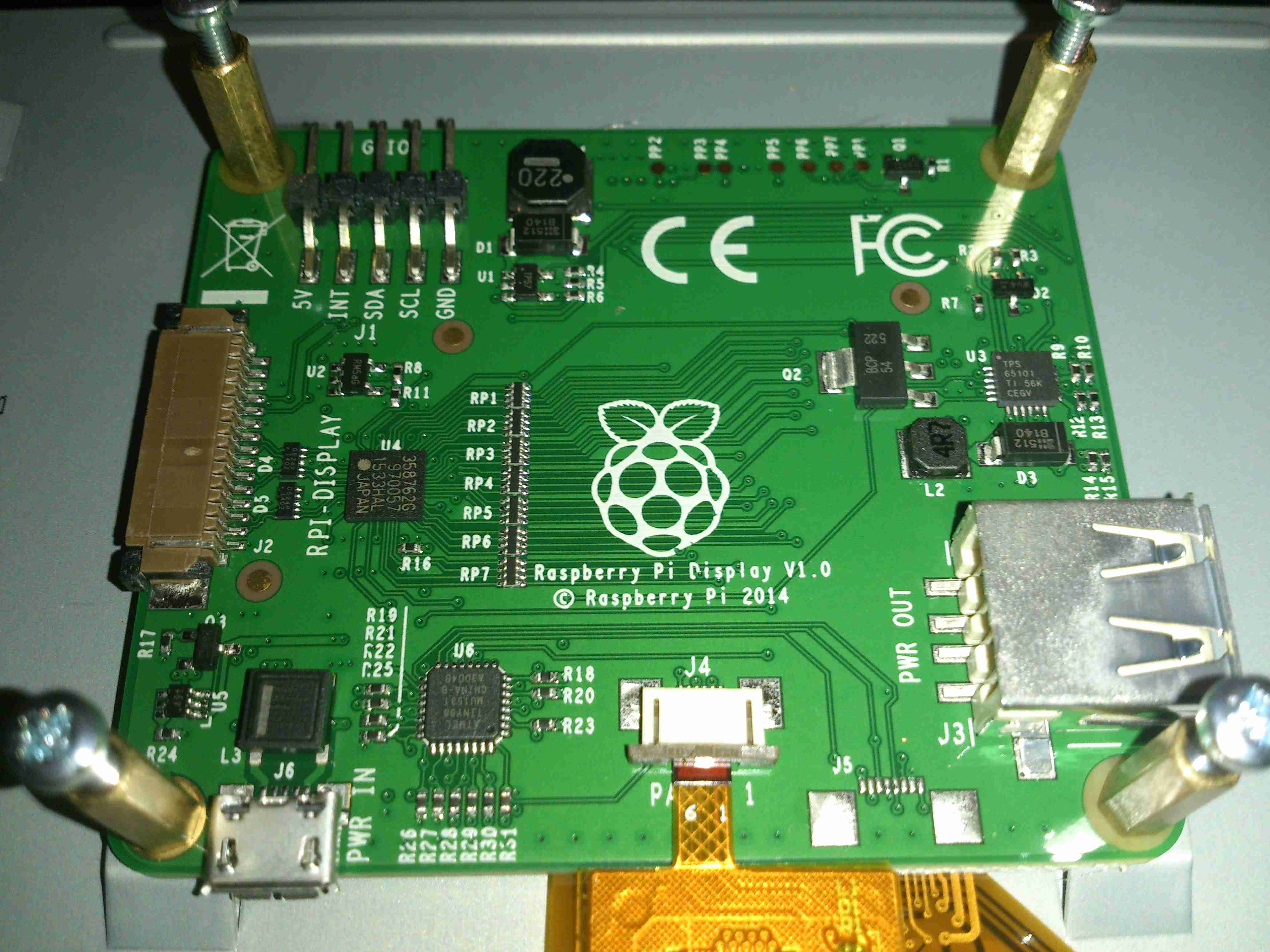
Interface PCB
The LCD itself is an RGB panel, to interface the Pi via the MIPI DSI port, some signal conversion is required. A small PCB is mounted on the back of the LCD to do this conversion. It also handles the power supply rails required by the LCD itself & interfacing the touch screen.
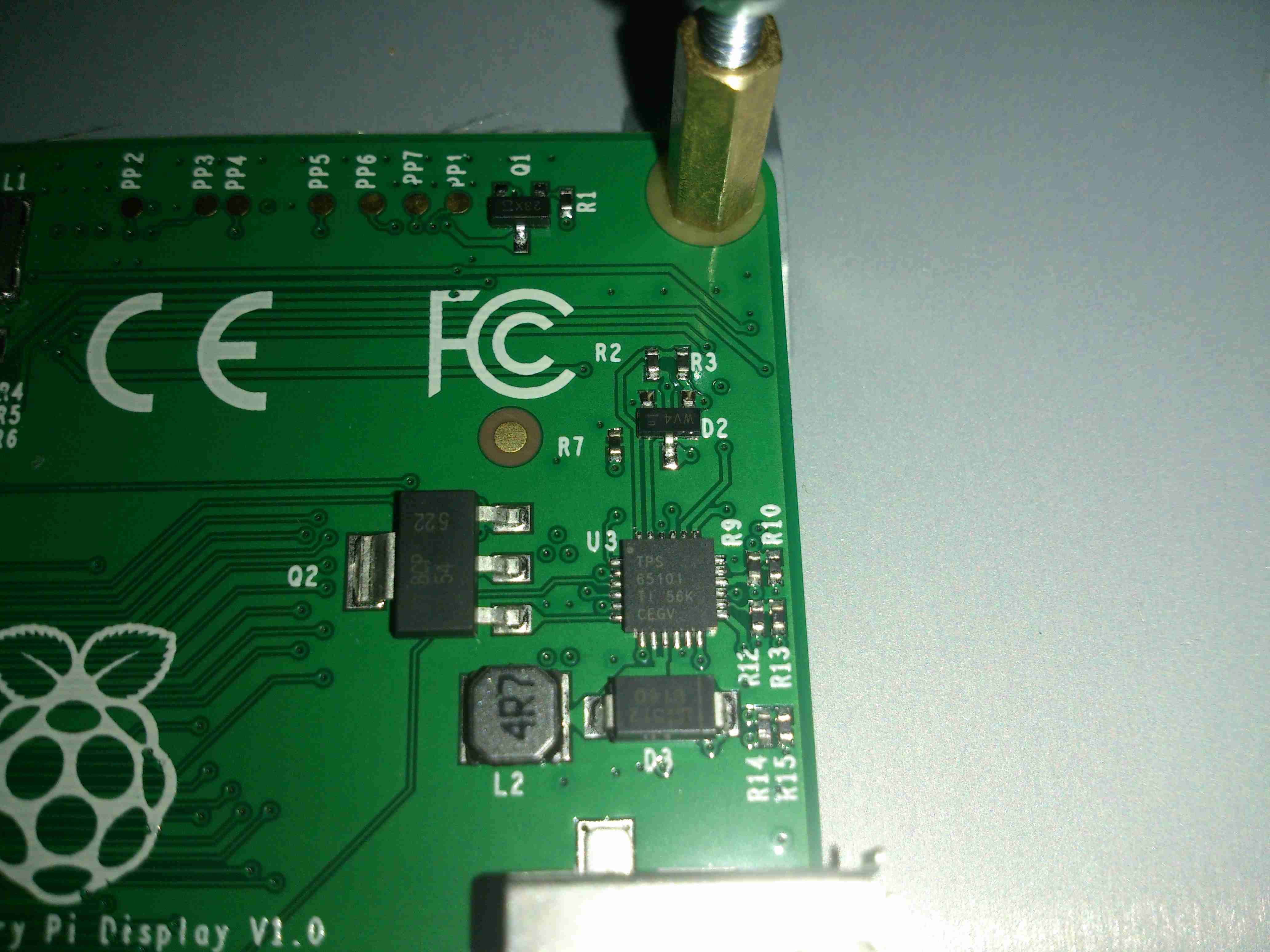
LCD Power Supply
Taking care of the power supply is a Texas Instruments TPS65101 triple output LCD power supply IC. This also has a built in linear regulator to supply 3.3v for the rest of the circuitry on board. The large transistor to the left of the IC is the pass transistor for this regulator.
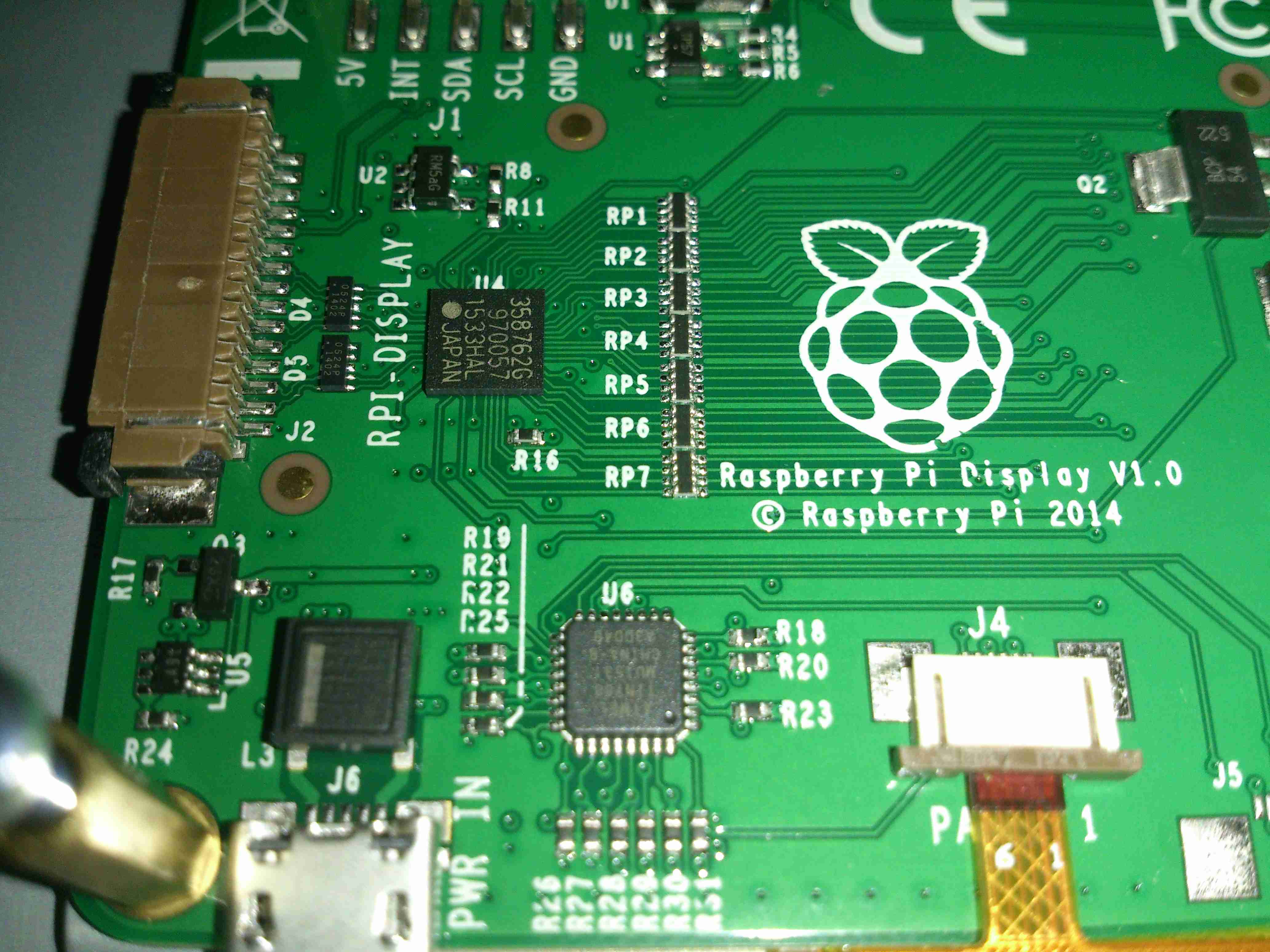
Main Controller
The video signal comes in on the FFC connector on the left, into the BGA IC. I’ve not managed to identify this component, but it’s doing the conversion from serial video from the Pi to parallel RGB for the LCD.
There’s also an Atmel ATtiny88 on the board below the main video conversion IC, not sure what this is doing.
The touch controller itself is mounted on the flex of the LCD, in this case it’s a FT5406.
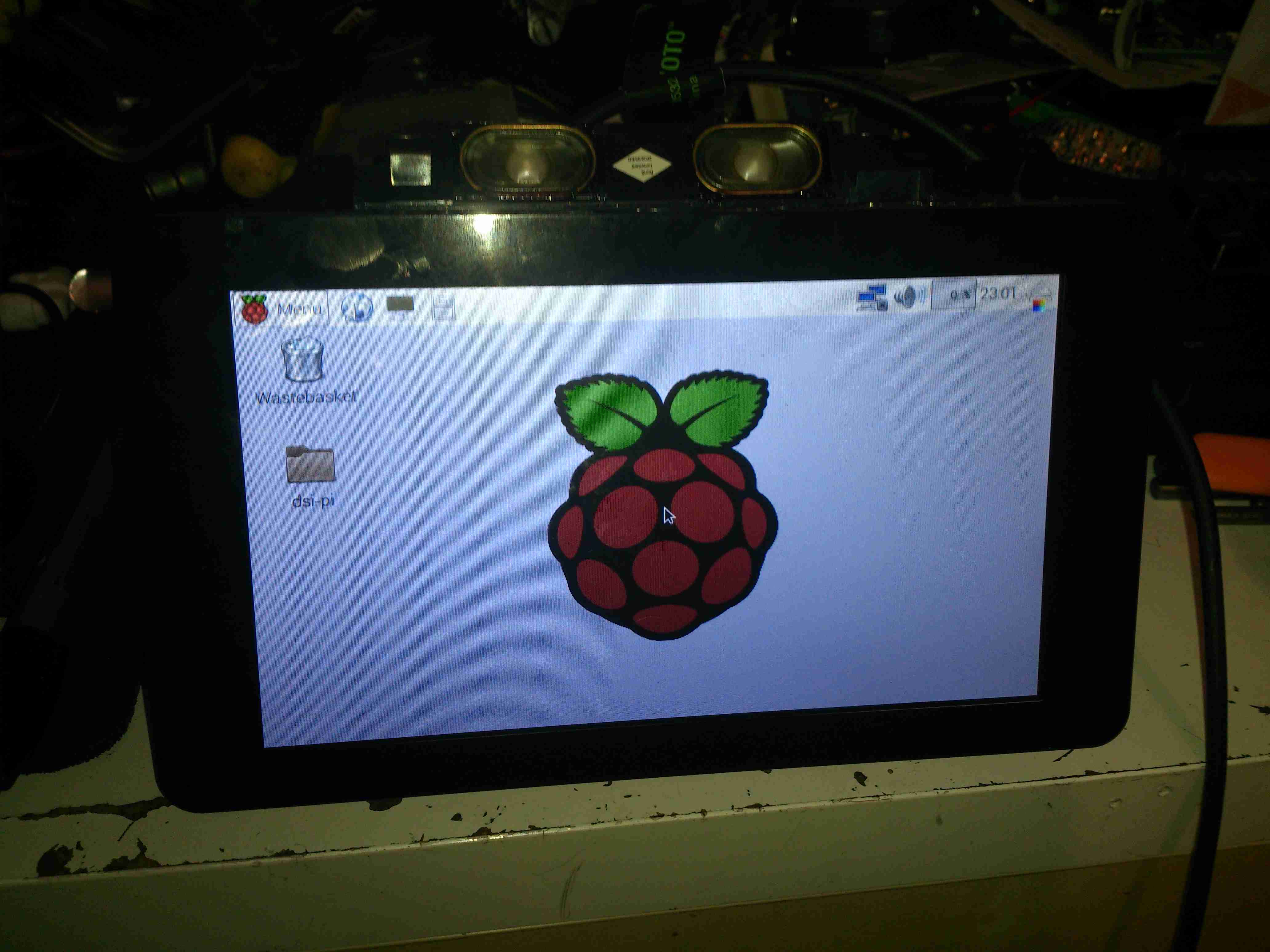
Raspberry Pi LCD
Here’s the LCD in operation. It’s not the highest resolution out there, but it leaves the GPIO & HDMI ports free for other uses.
Pi Mounted
The Pi screws to the back of the LCD & is connected with a flat flex cable & a pair of power jumpers. I’ve added a couple of small speakers to the top edge of the LCD to provide sound. (More to come on this bit).
To help improve the privacy of my blog readers, I’ve now enabled SSL support, with help from the guys over at Let’s Encrypt, supplying a free certificate.
Since Let’s Encrypt is still in closed beta, I won’t be forcing the use of SSL, but if you want to switch over to the SSL version of the site, click HERE!
It’s been a while since I’ve done a proper radio based post, so it’s a bit of a shame that I have to start off with a rant, but it’s required in this case.
One of the local 70cm repeaters, GB3WP seems to have many problems. The largest one seems to be G6YRK, the repeater keeper.
I had heard rumours of the repeater suddenly going off air getting switched off when either an M3/M6 or 2E0/2E1 was using it. At the time I thought no fellow ham could be quite that petty.
What callsign I or anybody else has should not make a shred of difference whether we should be allowed on the air or not. I personally keep my operating standards as high as possible, way above and beyond what Ofcom stipulates in the licence terms, as it’s part of making the hobby enjoyable for everyone. Seems that not everyone feels the same (in my experience, the older generation of hams, some of whom believe that the tests these days are far too easy, etc, etc).
Then I got proved wrong.
I was doing some handheld radio testing with M3HHY over at Distant Signal Radio on GB3WP, as at the time GB3MR was having some issues with the local pirate (see my previous posts for more info on that prat).
Within a couple of minutes of us establishing a QSO, the repeater suddenly stopped responding. After trying to get back in for a good 15 minutes, it came back on air again.
The instant we gave our callsigns, off it went, into the ether. No response.
This behaviour continued for nearly an hour, and after trying to contact YRK directly, we gave it up as a bad job, with quite a bit of pissed off added into the mix.
If I’d not heard stories of the repeater being turned off when the “wrong people” are using it, I might have put it down to dodgy repeater equipment, but even that didn’t make sense, as it had a definite pattern.
We both fired off an email to the Repeater Keeper, only to get no response from that either (surprise, surprise).
That was the last time I personally attempted to make use of GB3WP.
Until I was given an audio clip of G6YRK in action this evening.
Seems that not even M0 calls are immune from being wiped off the air by GB3WP. Chris, M0OGG, has apparently also had this issue with the repeater. Lucky for him, he had the opportunity to speak to the keeper directly about what went on.
Here’s the audio, I’ll pick each part out & go into a few opinions/observations below.
So, Chris (M0OGG) has asked a simple question, and been met with hostility. Dick Move Number 1.
YRK is clearly reluctant to go into “detail” on the air. Probably because he’s talking complete shite. Only when Lewis (M3HHY) joins in with a slightly more defensive tone does Steve (G6YRK) actually say what Chris has been “reported” for.
After all that it seems that an accusation of keying over other repeater users is the bullshit line of the day. (For the record, I know Chris, he’s not the type of person to key over another radio user, that behaviour in of itself is idiotic).
Apparently he has witnesses to this action, and he’s insisting that others were also involved. Not to mention the fact that RDF has been done on (I’m assuming) all of these “offenders”. G6YRK must have quite the army of hams with lots of spare time.
I’m not sure who the other station is, as he doesn’t give a callsign.
As Lewis jumps in & comments, the Repeater Keeper should be saying something to users he suspects of this kind of thing, in my opinion.
The real reason, of course, that he keeps turning the repeater off when others are using it is that he’s a passive-aggressive vindictive moron.
Surprise, surprise, he can’t remember the “exact date”, (because it never actually happened), it’s just “the other day, somebody did it”. Yeah, great evidence there Steve, because apparently the only person around at the time was Chris. How can he know this? When a repeater has a coverage area as wide as GB3WP, this guy is claiming that he knows that only a single person is listening? No, I think it’s bullshit too.
GB3WP Coverage Map
For reference, here’s the coverage map of the repeater. Steve G6YRK must be bloody psychic to make such a comment.
He then mentions a “friend” of Chris, but again refuses to give any names. Again I’m calling bullshit.
Swifty following this he goes into full kick-my-toys-out-of-the-pram mode because he’s been openly challenged.
While he’s correct in his statement that he can do as he pleases with the repeater, it’s not very good form to just switch the thing off when licenced users are having a perfectly valid QSO. If he doesn’t like people using the repeater, he should turn it off permanently & remove the listing from the repeater group.
After this, Steve makes the comment that he knows nothing of the repeater going off, as he’s been out all night. He mentions his Repeater Stasi again, and then makes a partial retraction of his previous statement, now that it “might” not have been Chris previously. Well Steve, we’re finally getting towards something that resembles truth. You’ve got absolutely no idea who is “keying people out”, if it’s even happening at all. So much for “having people all over the place” listening to where transmissions are coming from.
After Chris confronts him again, he returns to the fallback of that as the NoV holder it’s his prerogative to be able to switch the repeater off whenever he pleases.
When confronted with the fact that people pay into the repeater group to help keep them running, he claims that Chris’ signal is breaking up. My arse. Every other station on the repeater can hear him fine.
There’s probably more to add to this, so if I get any more relevant information from other sources I’ll add on to the saga.
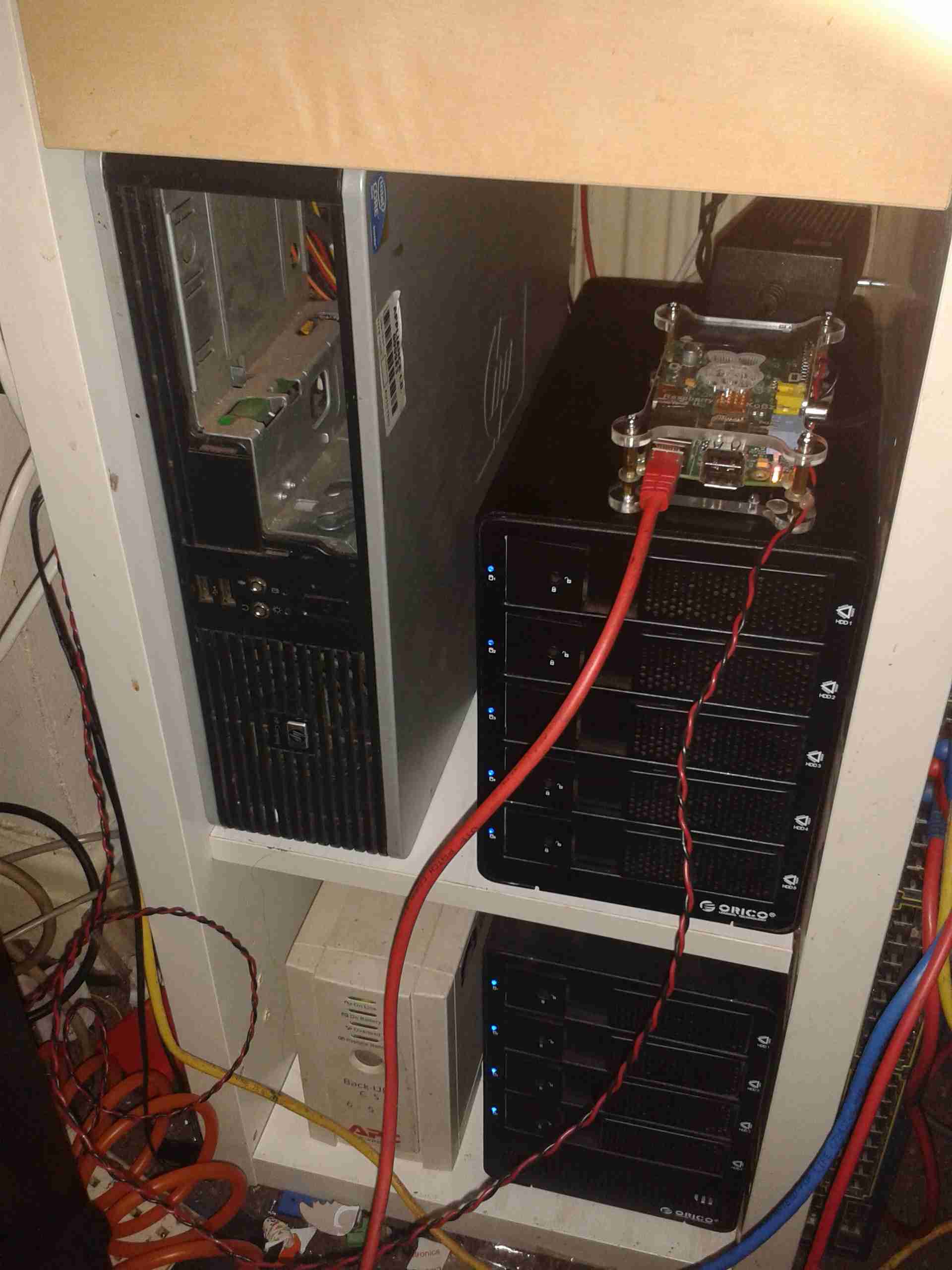
My main bulk storage for the home LAN is a bank of 4TB drives, set up in a large RAID6 array. Due to a brownout this evening on the +12v supply for one of the disk banks, I’ve had to start rebuilding two of the disks.
Core NAS
The total array size is 28TB after parity – 9 4TB disks in total. The disks are connected through USB3 to the file server.
mdadm Detail
Here’s the current status of the array. Two of the disks decided that they wouldn’t rejoin the array, so they got their superblocks cleared & readded manually. This forced the array into rebuilding.
Rebuild Progress
Rebuilding an array of this size takes a while, as can be seen from the image above, it’s going to take about 7200 minutes, or 5.2 days.
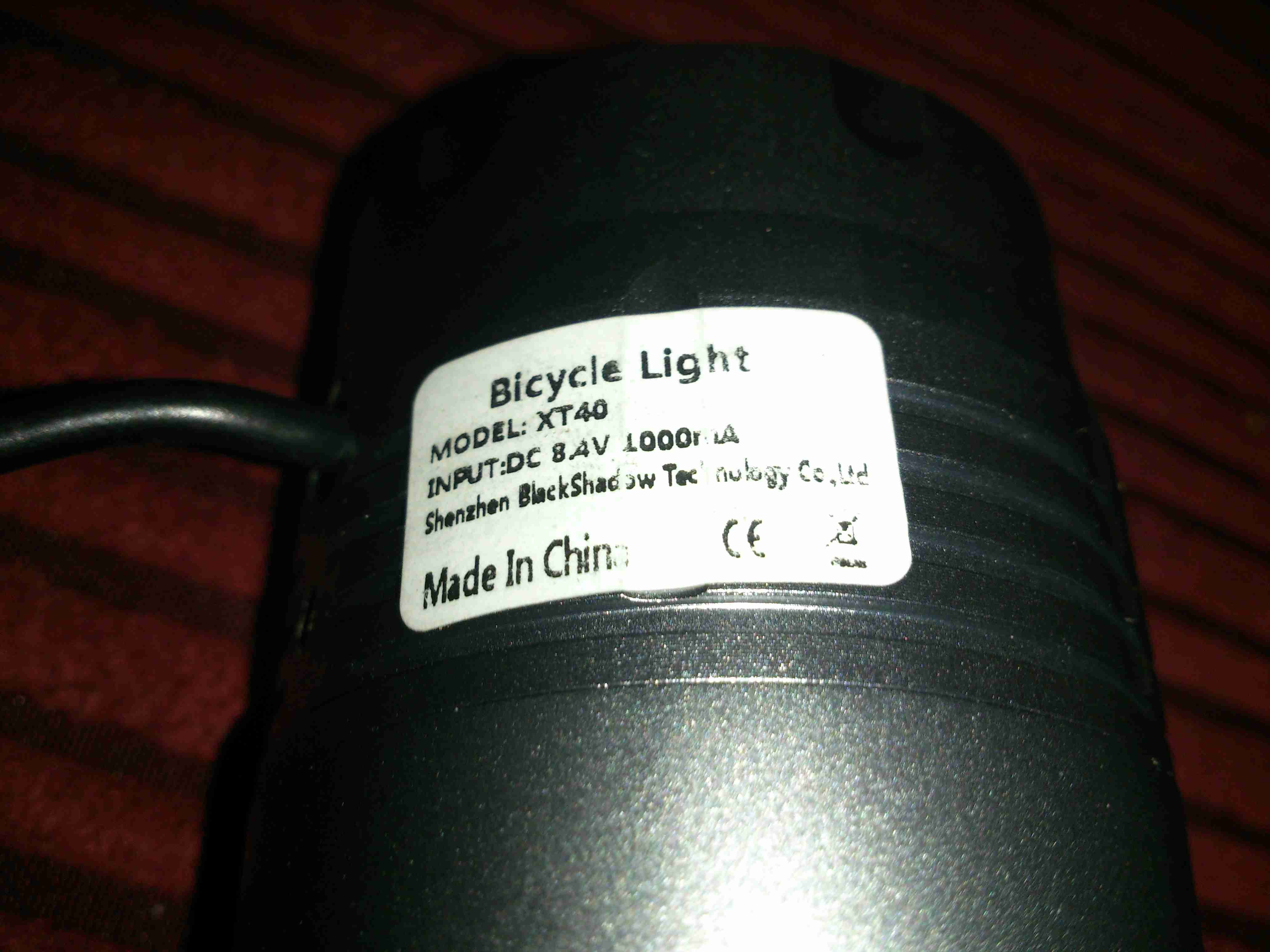
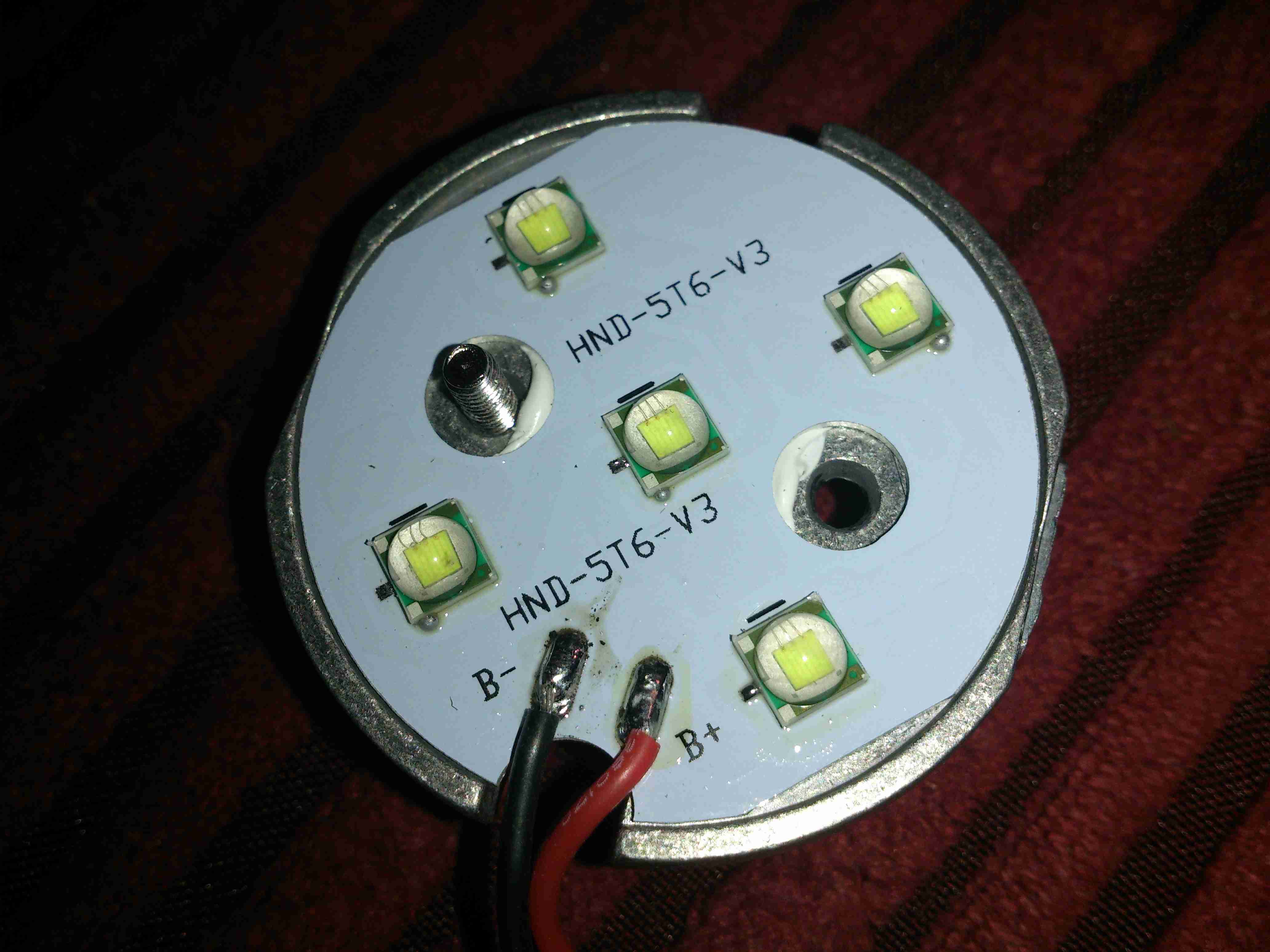
Here’s another torch from eBay, this time with 5 Cree XML-T6 LEDs.
Label
Having 5 Cree LEDs rated at up to 3A a piece, this light has the capacity to draw about 50W from it’s power supply. In this case though, current draw is about 1.5A at 12v input on the full brightness setting.
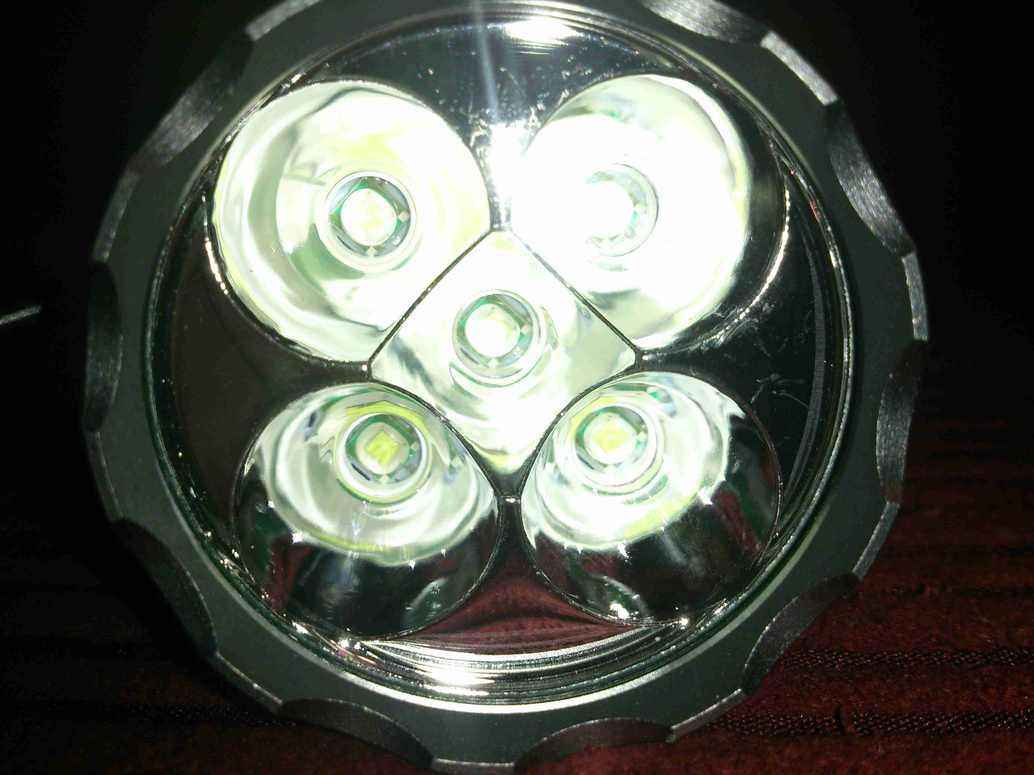
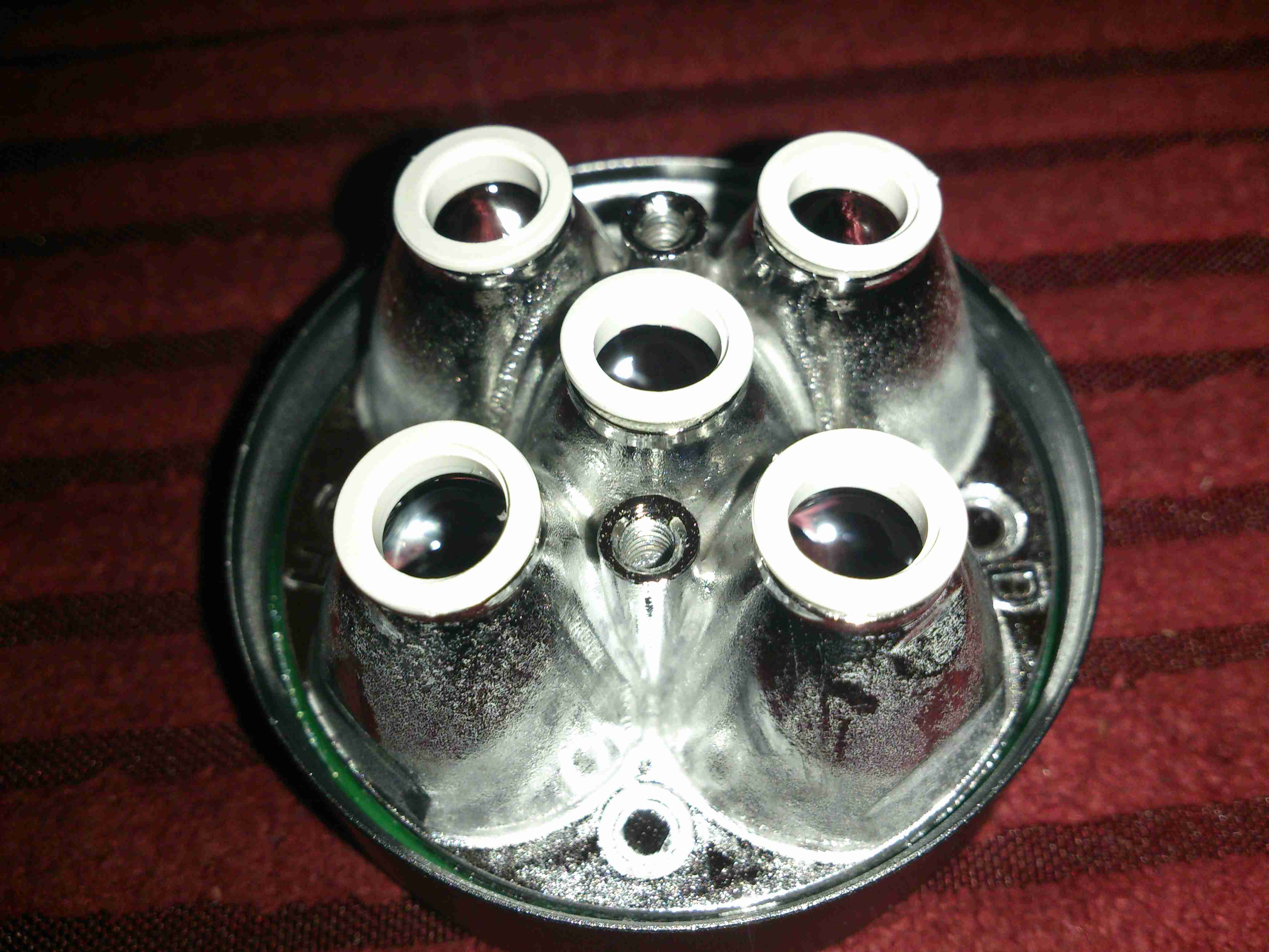
Cree LED Torch
Here’s the LEDs mounted into the reflector. Fitting this many high power LEDs into a small space requires some serious heatsinking. The casing is made of machined aluminium.
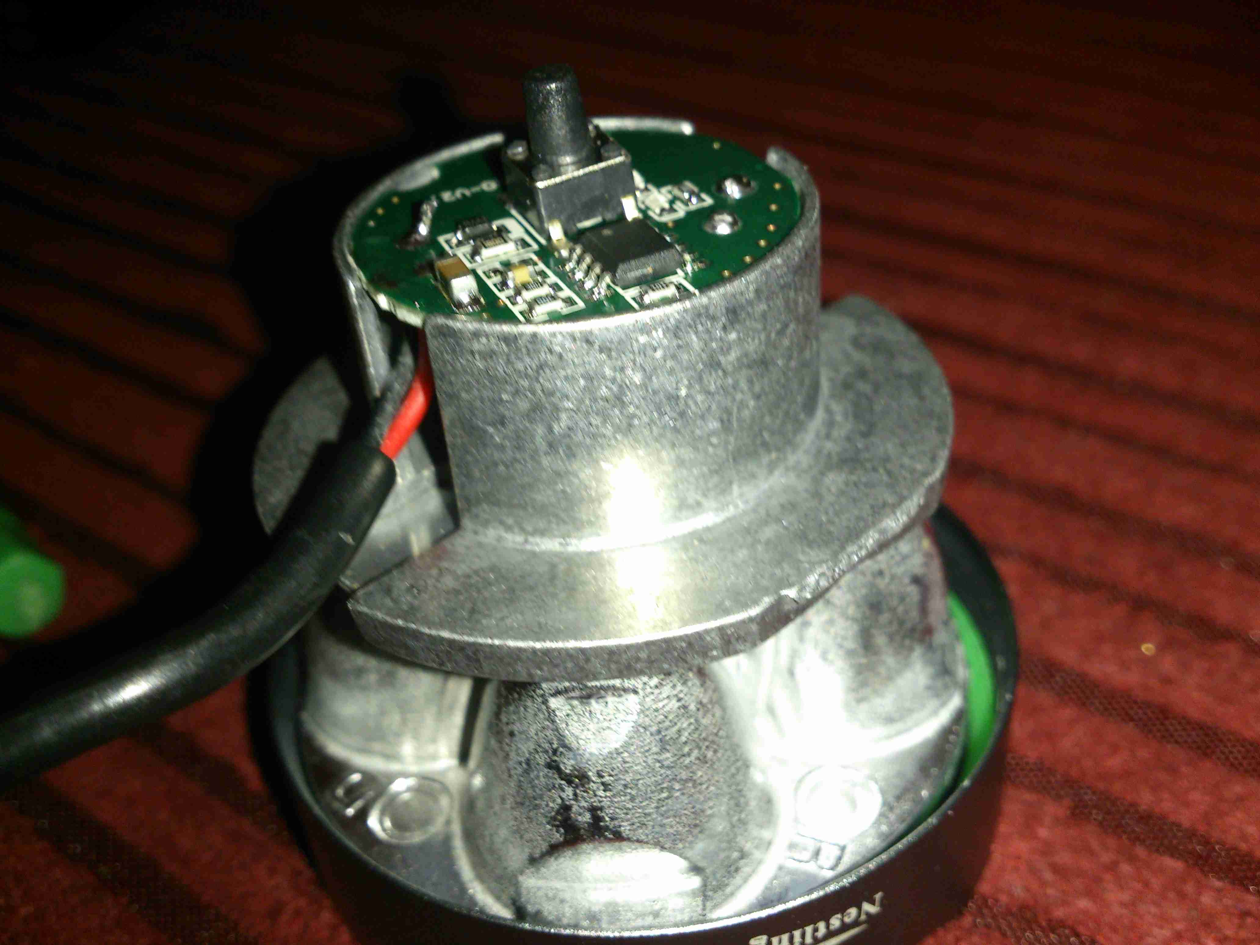
LED Module
Unscrewing the front bezel allows the internals to come out. The core frame & reflector is all cast alloy as well, for heatsinking the LEDs. The controller PCB is mounted into a recess in the back of the LED mount.
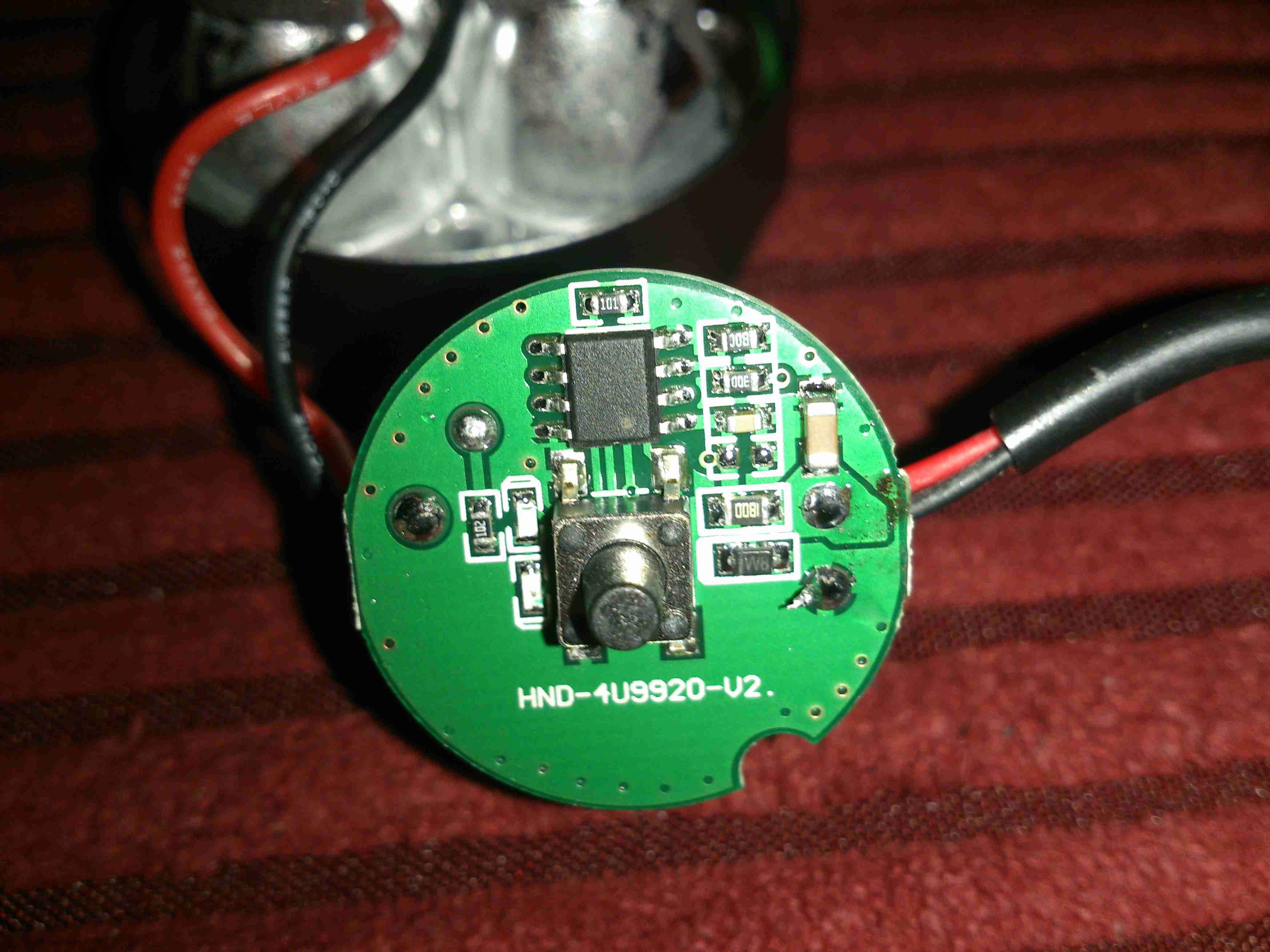
Controller
Here’s the controller itself. The usual small microcontroller is present, for the multiple modes, and handling the momentary power switch.
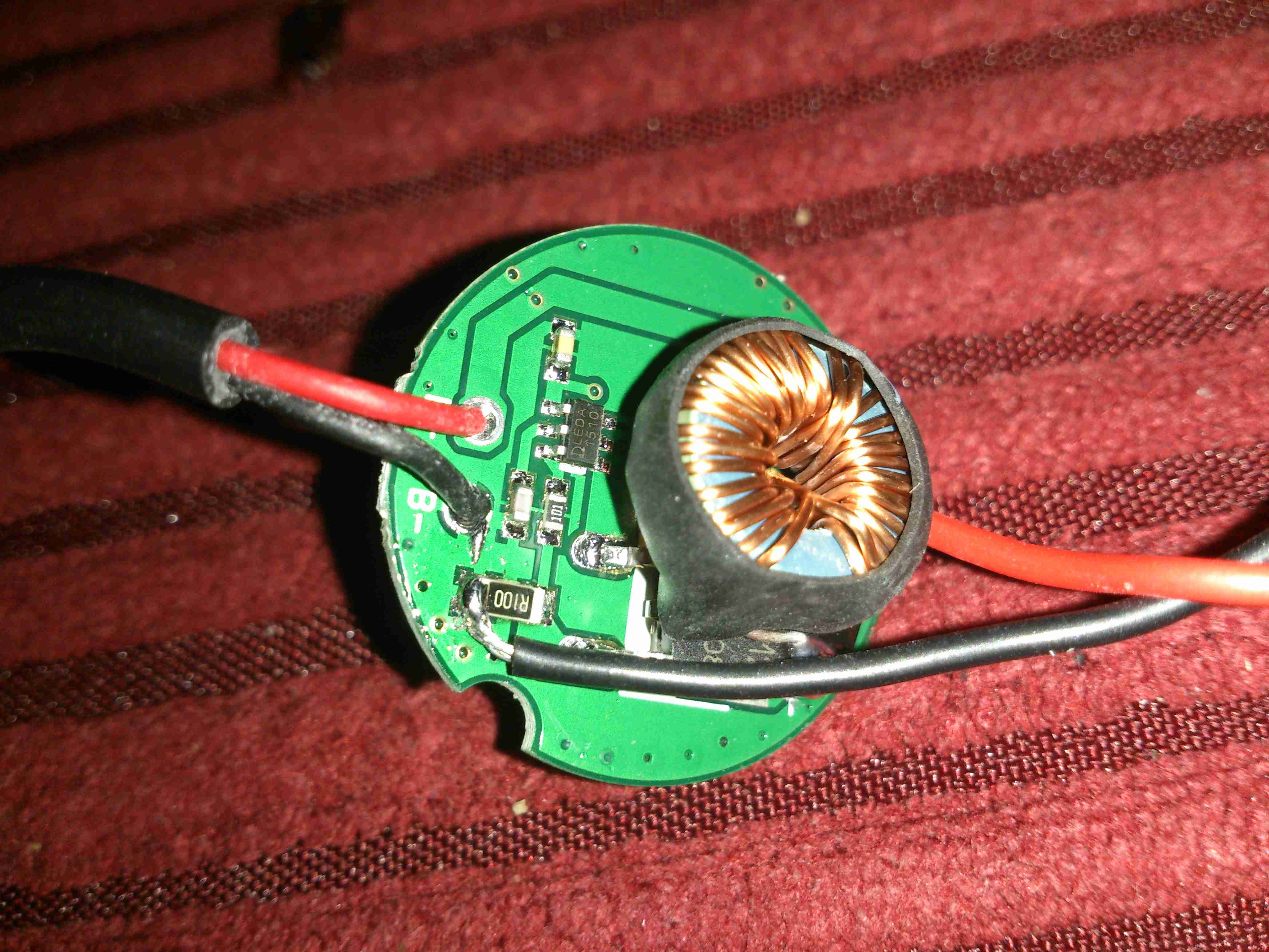
Switching Inductor
As all the LEDs on this torch are connected in series, their forward voltage is ~12-15v. The battery is an 8.4v Li-Ion pack, so some boost conversion is required. This is handled by the circuitry on the other side of the board, with this large power inductor.
Reflector
The reflector screws onto the front of the LED array, centered in place with some plastic grommets around the LEDs themselves.
LED Array
Finally for the torch, the LED array itself. This is attached to the frame with some thermal adhesive, and the LEDs themselves are mounted on an aluminium-core PCB for better heat transfer.
This module unsurprisingly generates quite some heat, so I have improved the thermal transfer to the outer case with some thermal grease around the outer edge.
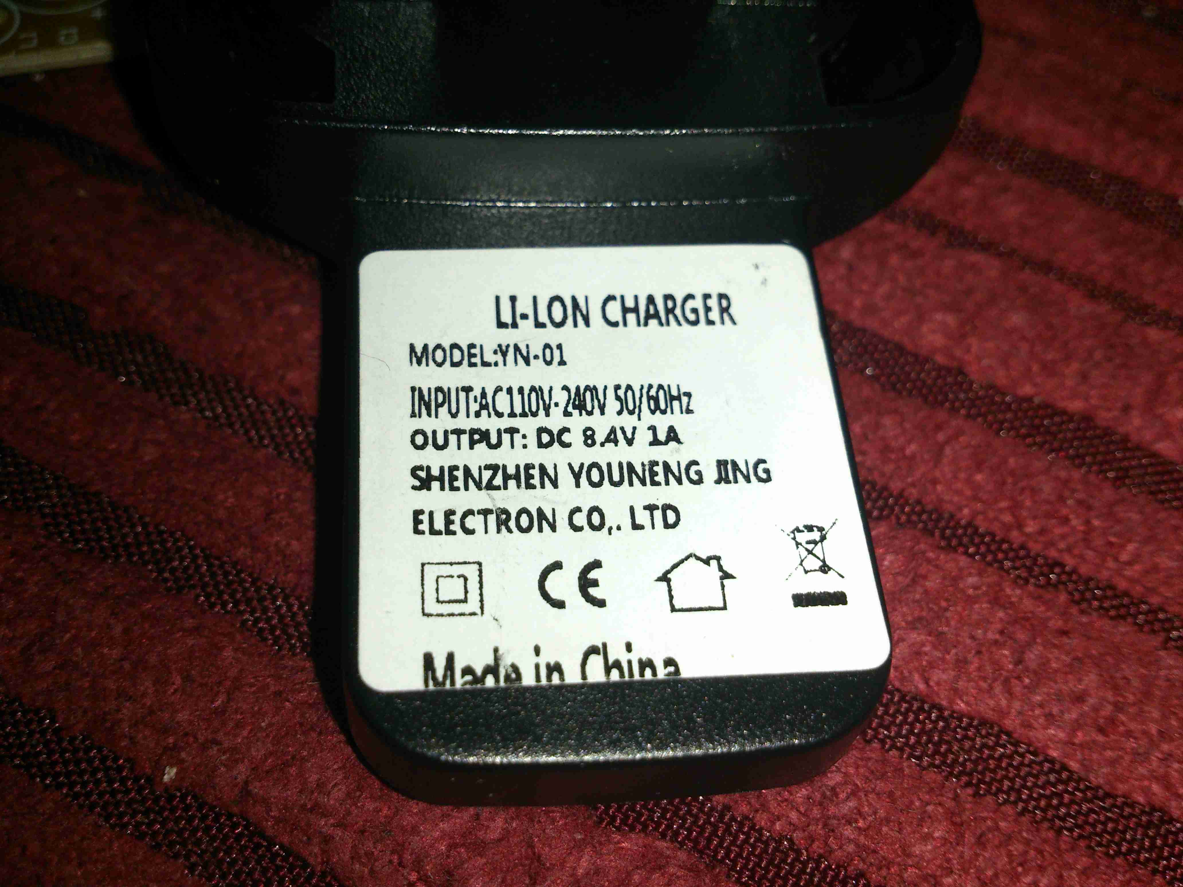
Charger
The supplied charger is the usual Chinese cheapy affair, claiming an output current of 1A at 8.4v. I never use these chargers, so they get butchered instead.
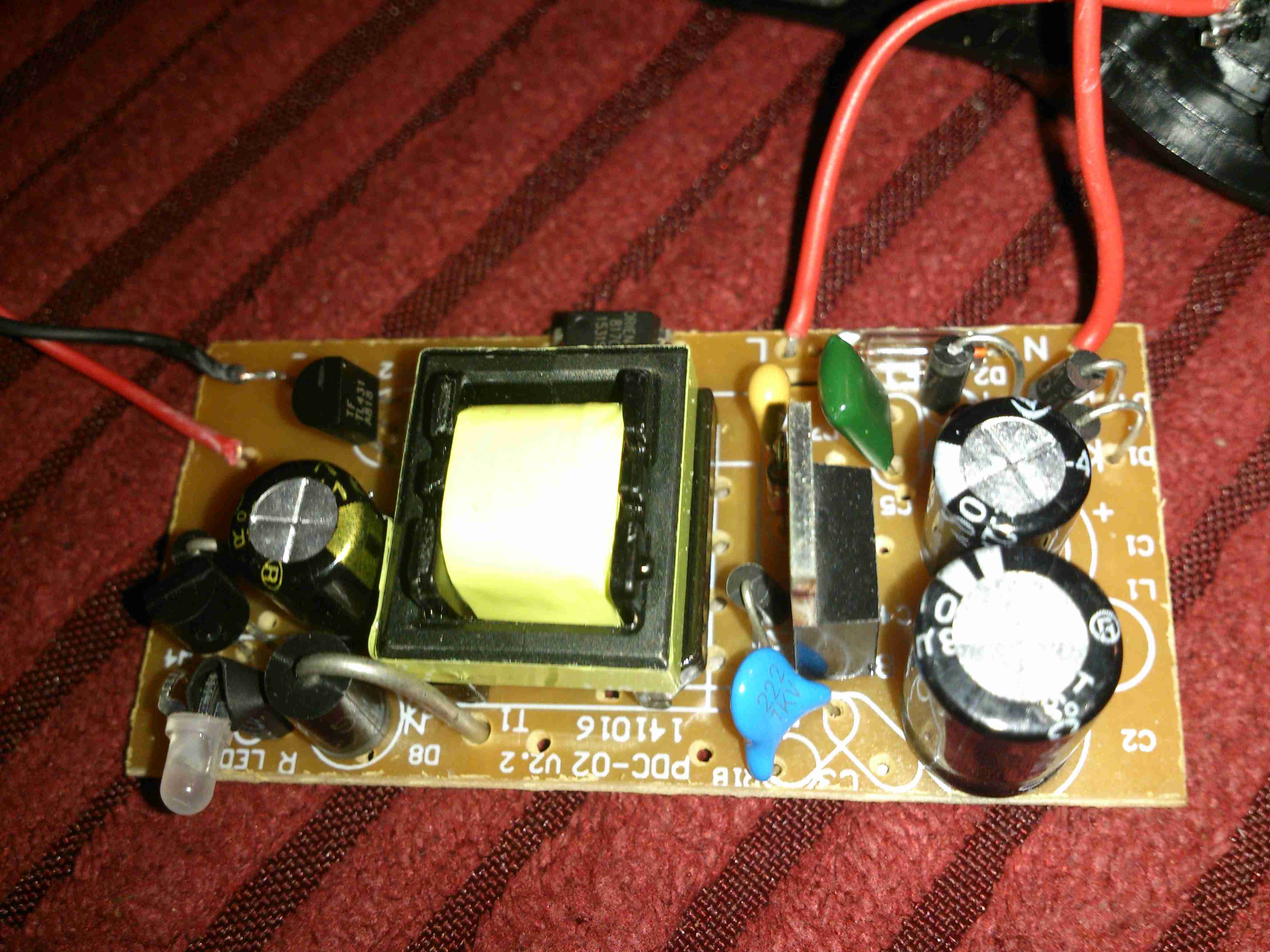
Charger PCB
Here’s the main PCB. Overall the construction isn’t that bad, the input mains is full-wave rectified, but there is little in the way of RFI filtering. The supply is fused, but with an absolutely tiny glass affair that I seriously doubt has the ability to clear a large fault current.
Like many cheap supplies, the output wiring is very thin, it’s capacity to carry 1A is questionable.
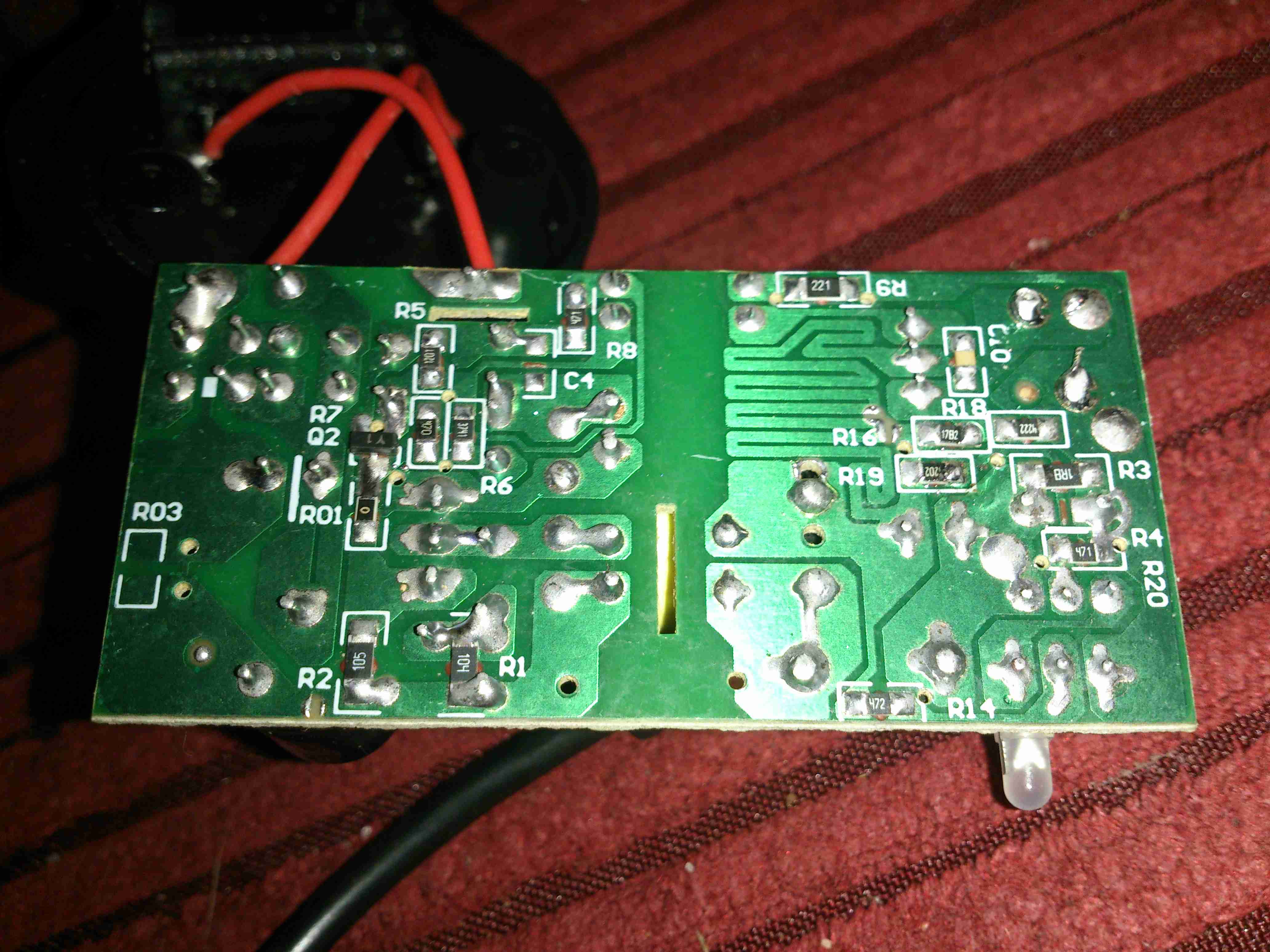
PCB Reverse
On the reverse side, there’s a nice large gap between the mains side & the low voltage output. There’s even an anti-tracking slot under the optoisolator.
As supplied, the RTL type tuner dongles are a little fragile, especially when they’ve got a rather heavy coax feeder attached for Ham Radio use.
The MCX antenna connectors on the tuner can’t stand up to much abuse, and even the USB plug rips itself from it’s mounts after a while with a heavy weight on the end. Since this dongle sits in my radio go bag, it definitely needed some protection & support.
PCB
The PCB itself is removed from it’s flimsy plastic casing, the USB plug is desoldered from the board.
To the exposed pads, a USB cable is soldered, giving much more flexibility in where the tuner is placed.
Instead of using the MCX antenna connector on the PCB, the coax is stripped & soldered direct to the PCB itself, as this connector has become unreliable.
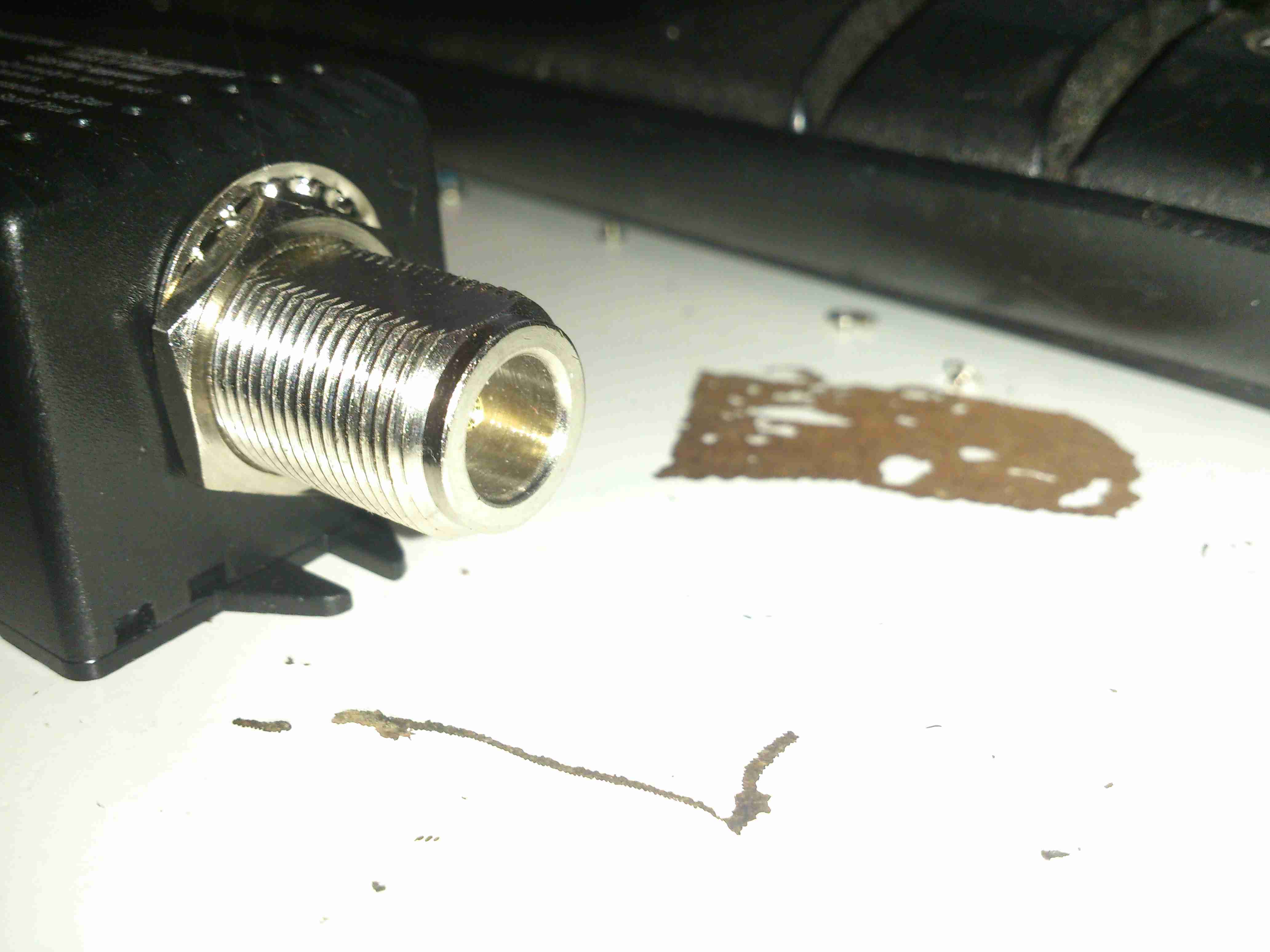
N-Connector
To get the RF into the device, the case is fitted with an N connector, as is everything else in my shack.
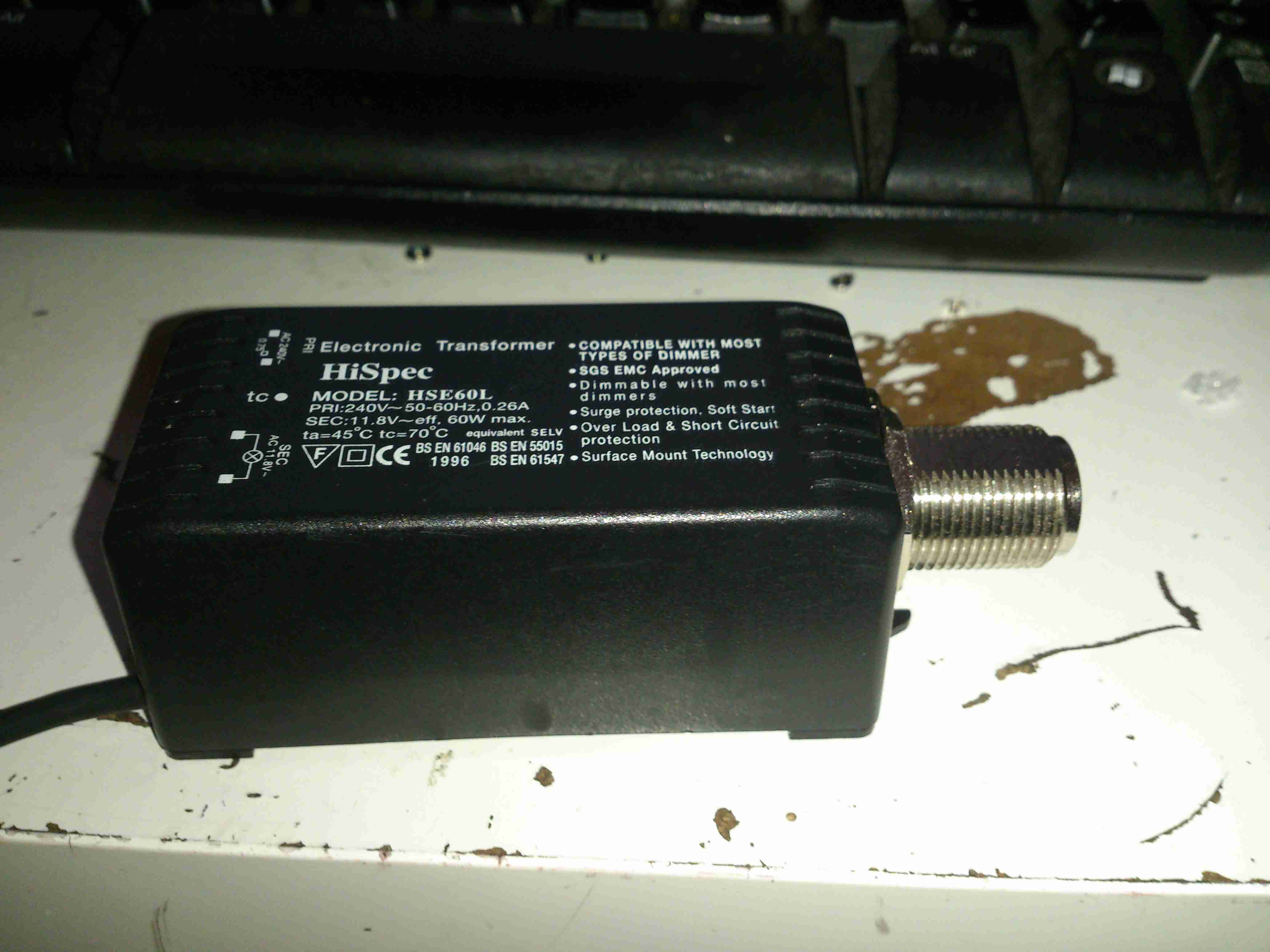
Boxed
The box used is a surplus one which previously housed an electronic lighting transformer. This would be very easy to waterproof as well, for more protection against outdoor use.
Here’s a quick look at one of the now surplus cards from my old networking system, a MiniPCI Wireless interface card.
Card Overview
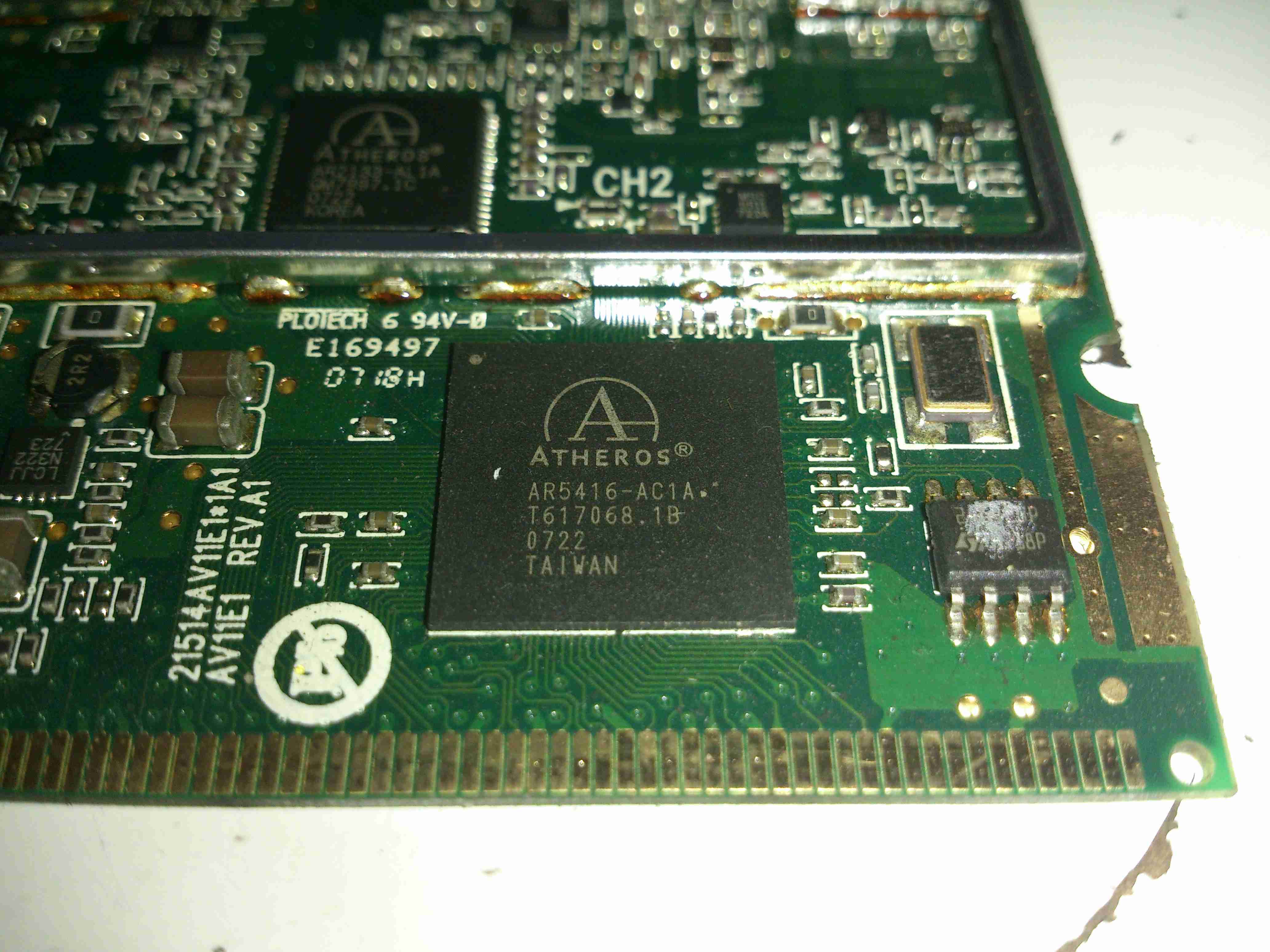
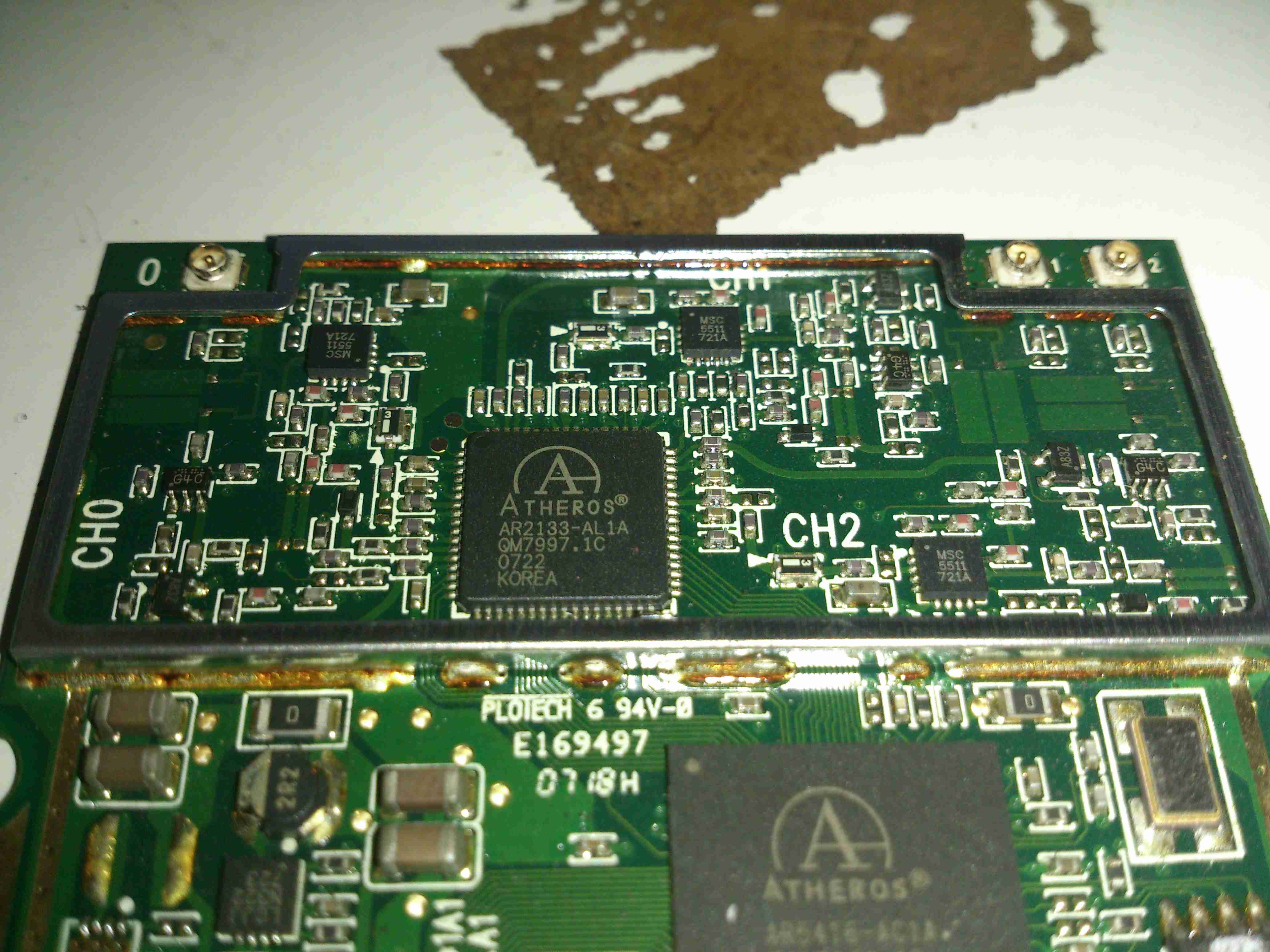
This is an older generation card, one of the first with Wireless N support on 2.4GHz.
PCI Chipset
Network PHY & firmware EEPROM. Power supply stuff is over to the left.
RF Transceiver
Inside the shield is the RF Transceiver IC & it’s associated RF power amplifier ICs for each antenna. These power amplifiers are LX5511 types from Microsemi, with a maximum power output of +26dBm.
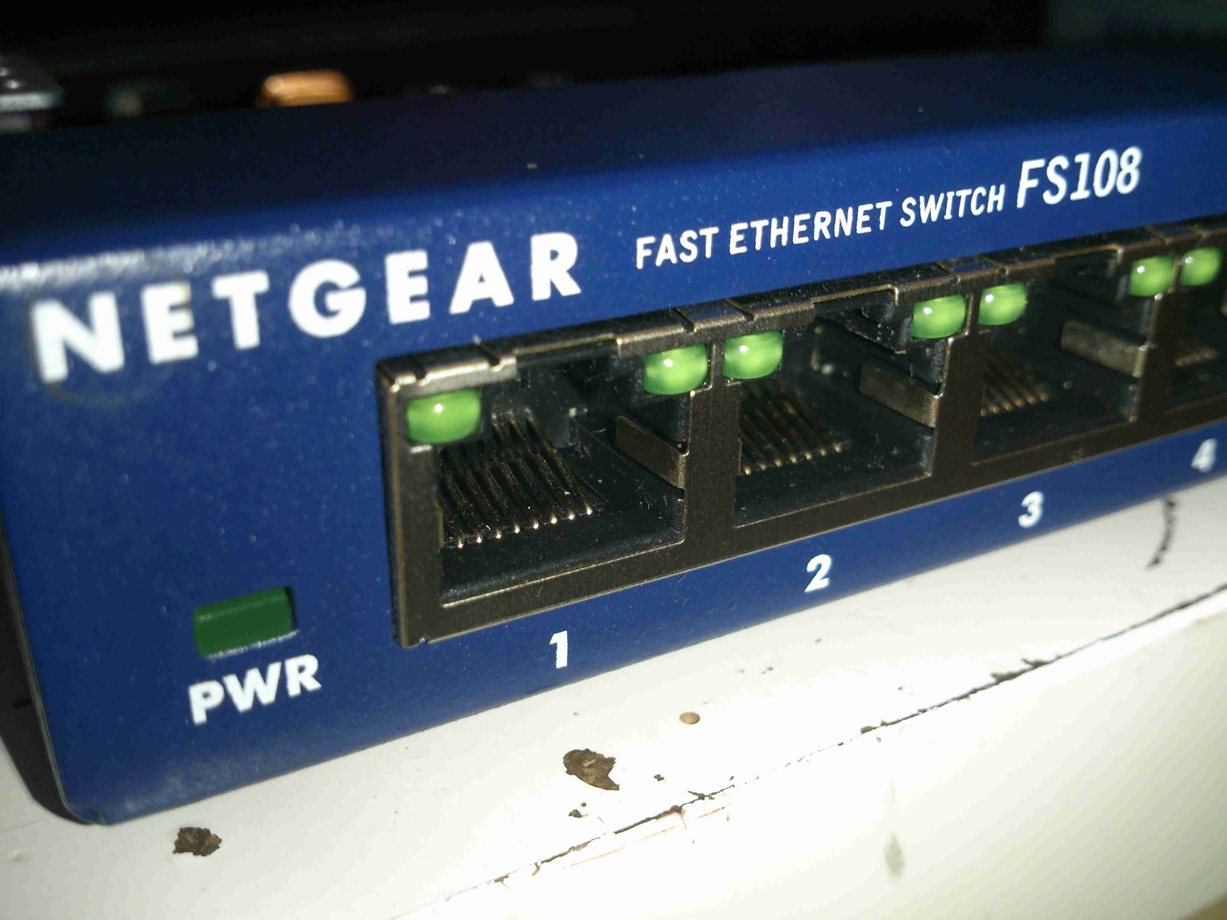
During the replacement of the networking onboard nb Tanya Louise with gigabit, the main 8-port distribution switch was also changed. Here’s a quick teardown of the old one.
Netgear FS108
This has been quite a reliable switch for the internal networking on board, but the time has come to switch over to something a little faster. This switch will be getting repurposed for the slower devices on my network, such as the radiation monitor & the raspberry Pi systems.
Cover Removed
Here’s the top removed from the switch. It’s a very simple construction, with a small power supply section & the main switch IC in the centre.
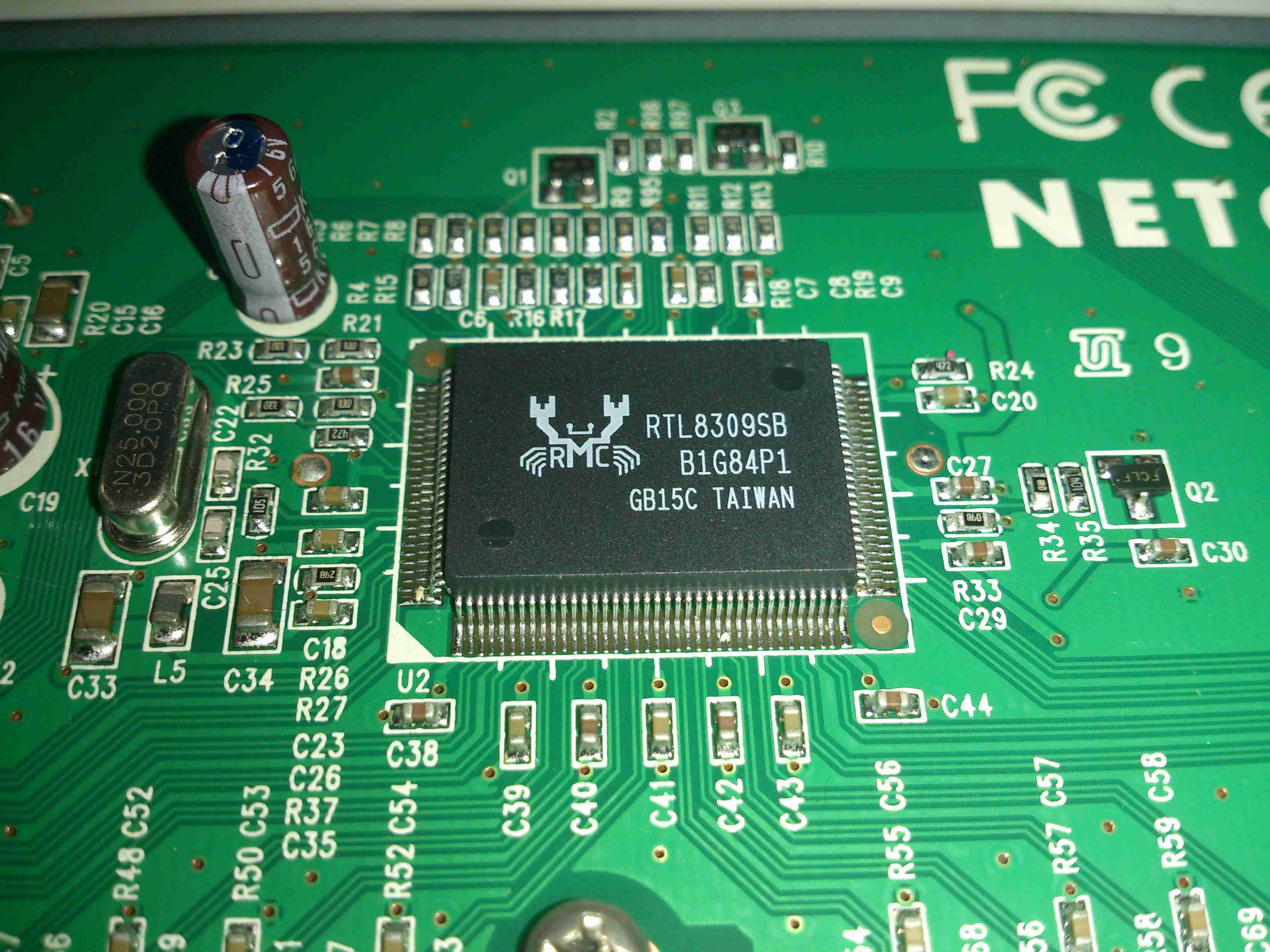
Main Switch IC
All the magic happens in this main IC, a Realtek RTL8309SB Fast Ethernet switch. This is a feature-packed IC, with support for VLAN tagging, but being in a small unmanaged switch the extra features aren’t used.
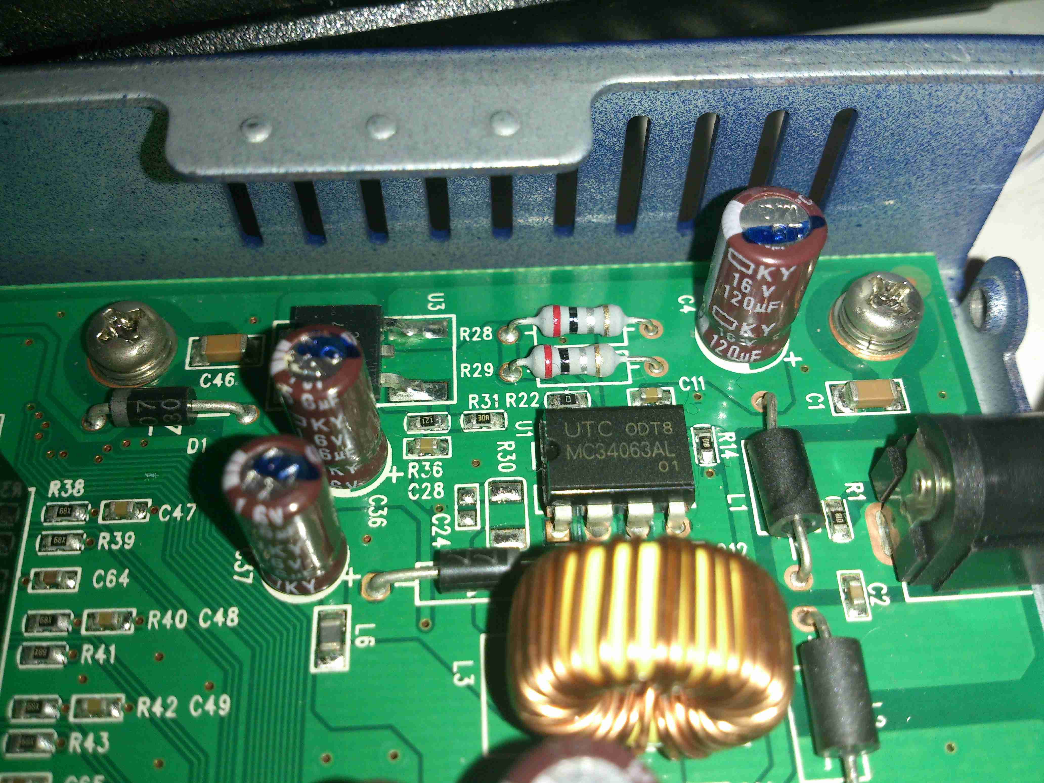
Power Supply
Main power supply is provided by a jelly bean MC34063 DC-DC converter, and an adjustable LM1117 linear regulator. Nothing much special here.
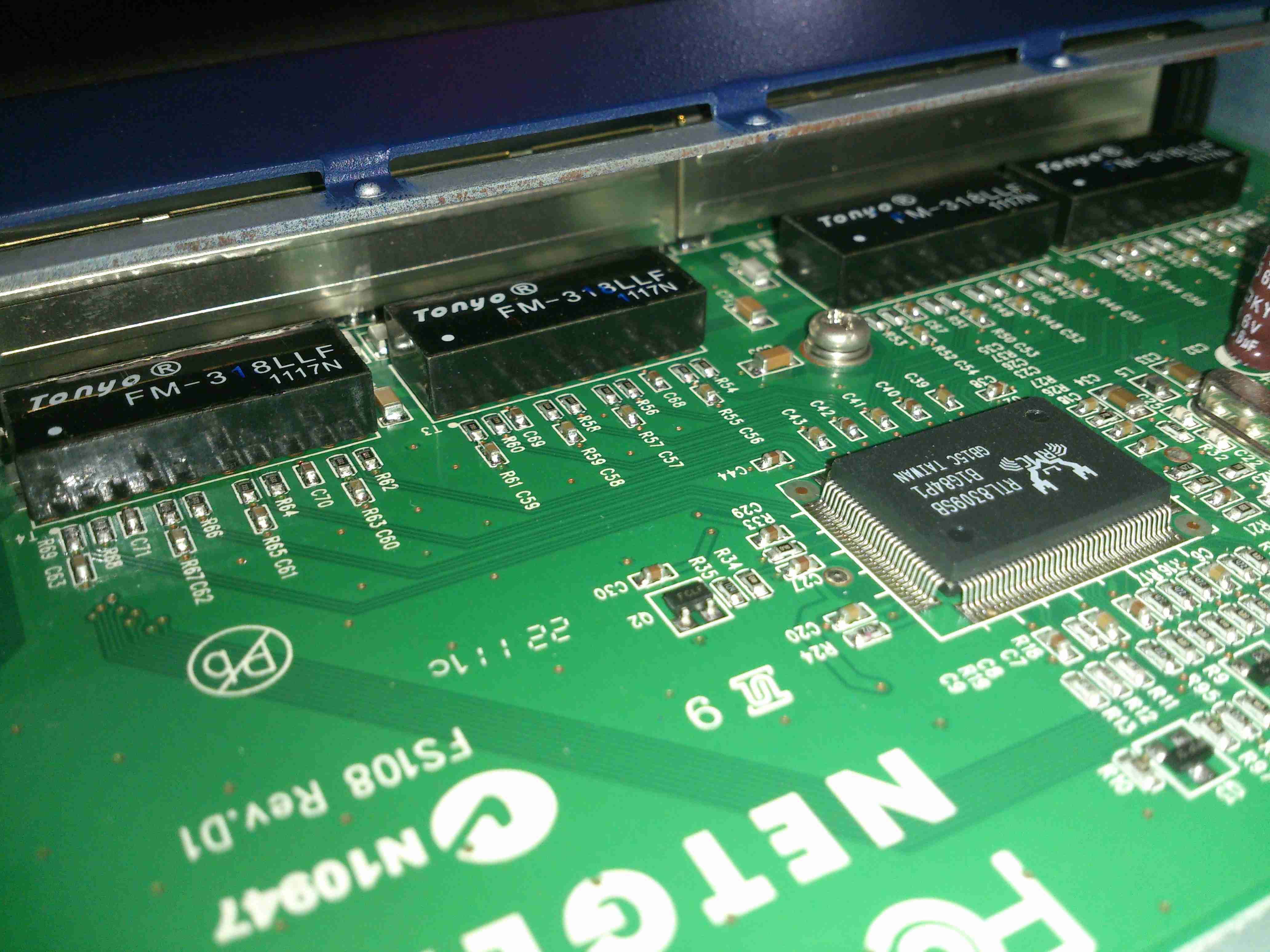
Ethernet Magnetics
The only other parts are the magnetics for the ethernet interfaces, behind the ports themselves.
Since the boat was still running it’s internal network on 10/100M speeds, an upgrade was decided on, the internal WiFi signal strength was also pretty poor further than a few feet from the NOC.
The new router is a Cisco/Linksys AC1750 model, with gigabit networking, and full 802.11ac 2.4/5GHz Wireless. This router also has a built in media server, print server, USB3 & USB2.
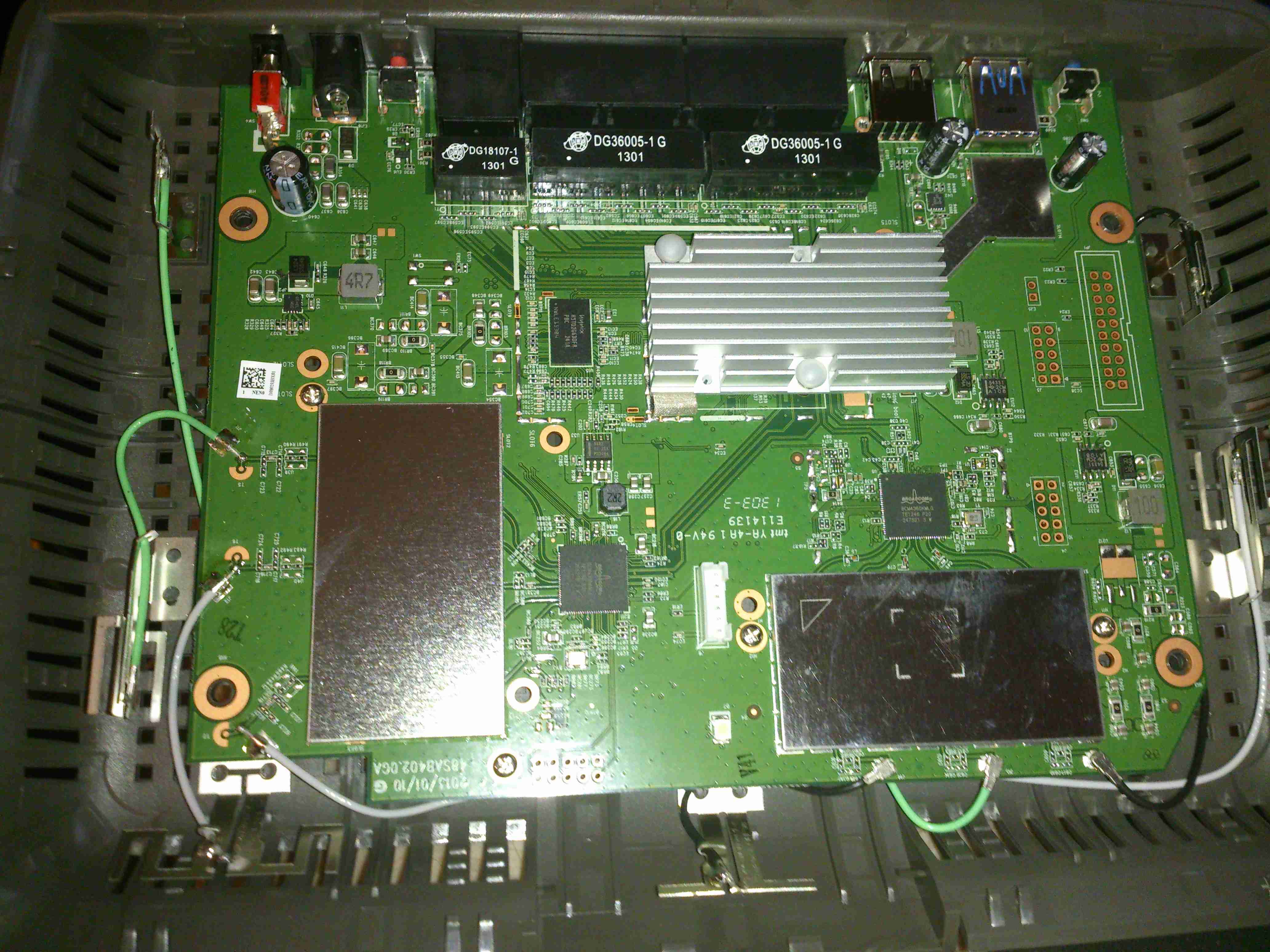
PCB Overview
Teardown time! Here’s the router with the cover removed. Most of the fun stuff is hidden under the shields, but these aren’t fully soldered down & the covers are removable. The 6 antennas can be seen spaced around the edge of the housing, the main CPU is under the large heatsink upper centre. The radio power amplifier stages are underneath the shields, while the main RF transceivers are just outside the shields.
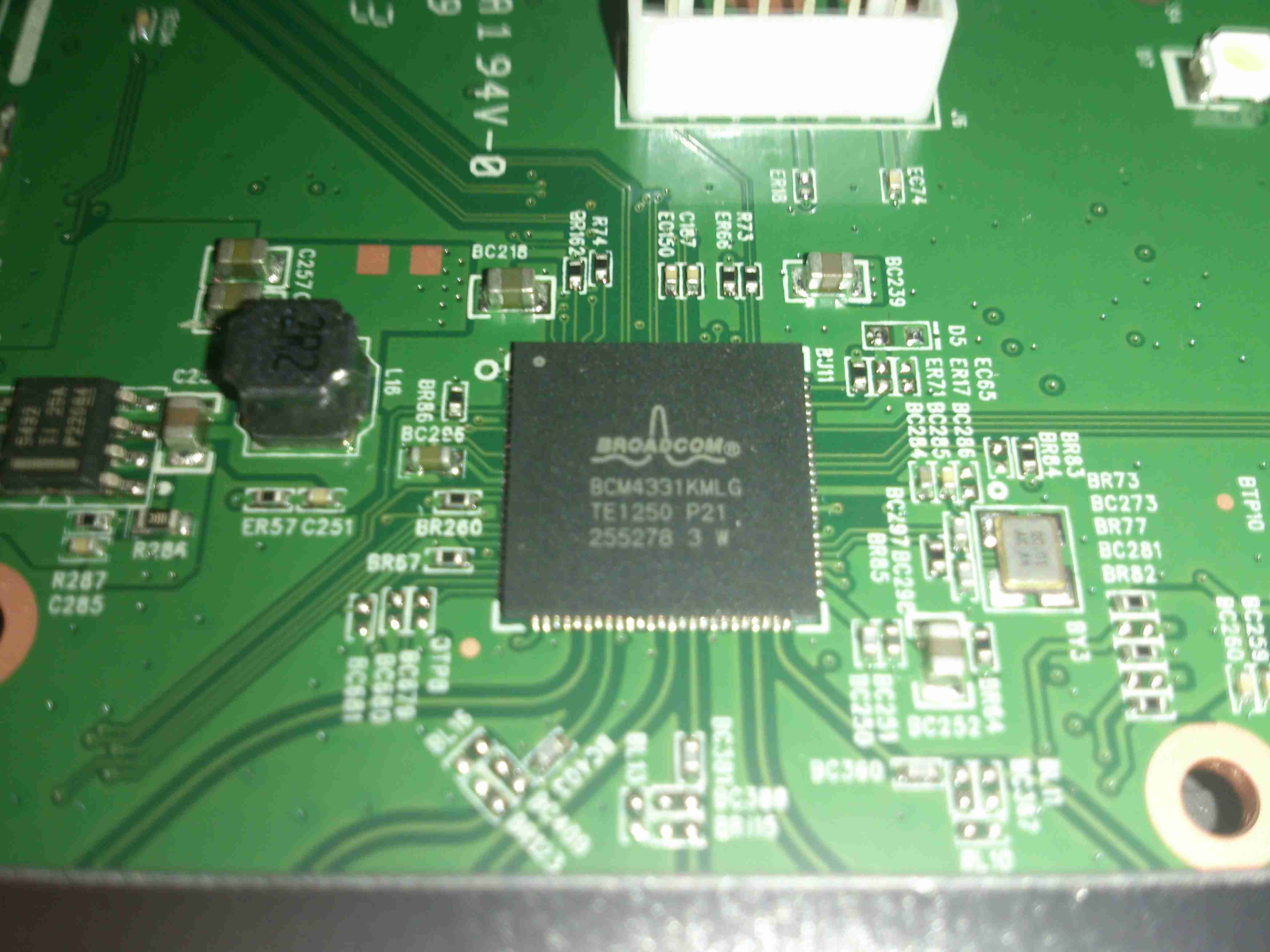
2.4GHz Transceiver
Wireless N is provided by a Broadcom BCM4331, this provides full dual-band 3×3 802.11n support. Being 3×3 it is actually 3 separate transceivers in a single package, to get much higher throughput rates of 600Mbit/s.
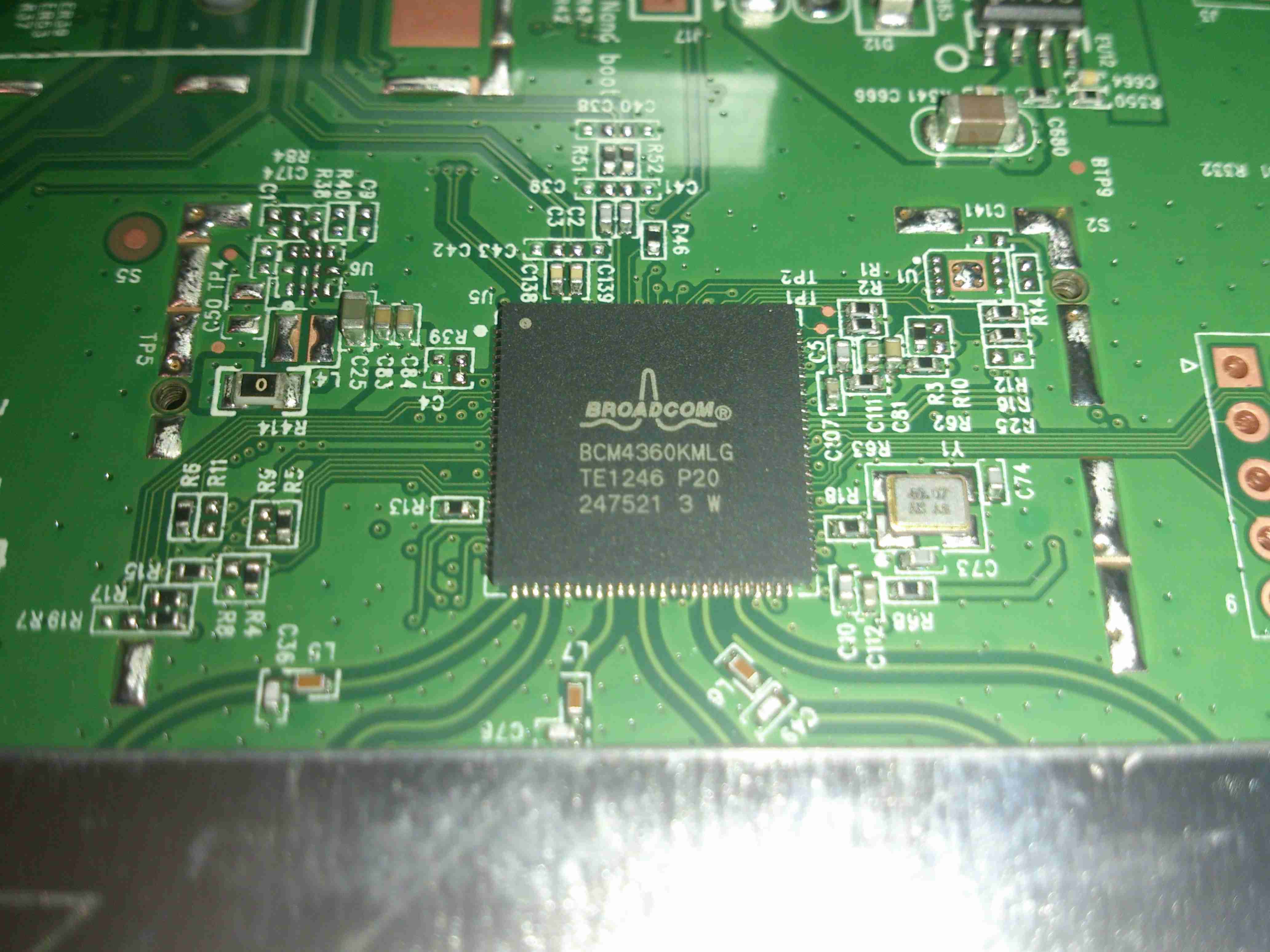
5GHz Transceiver
Wireless AC is provided by it’s sister IC, the BCM4360, with throughput speeds of 1.3Gbit/s. Both of these transceiver ICs connect back to the main CPU via PCI Express.
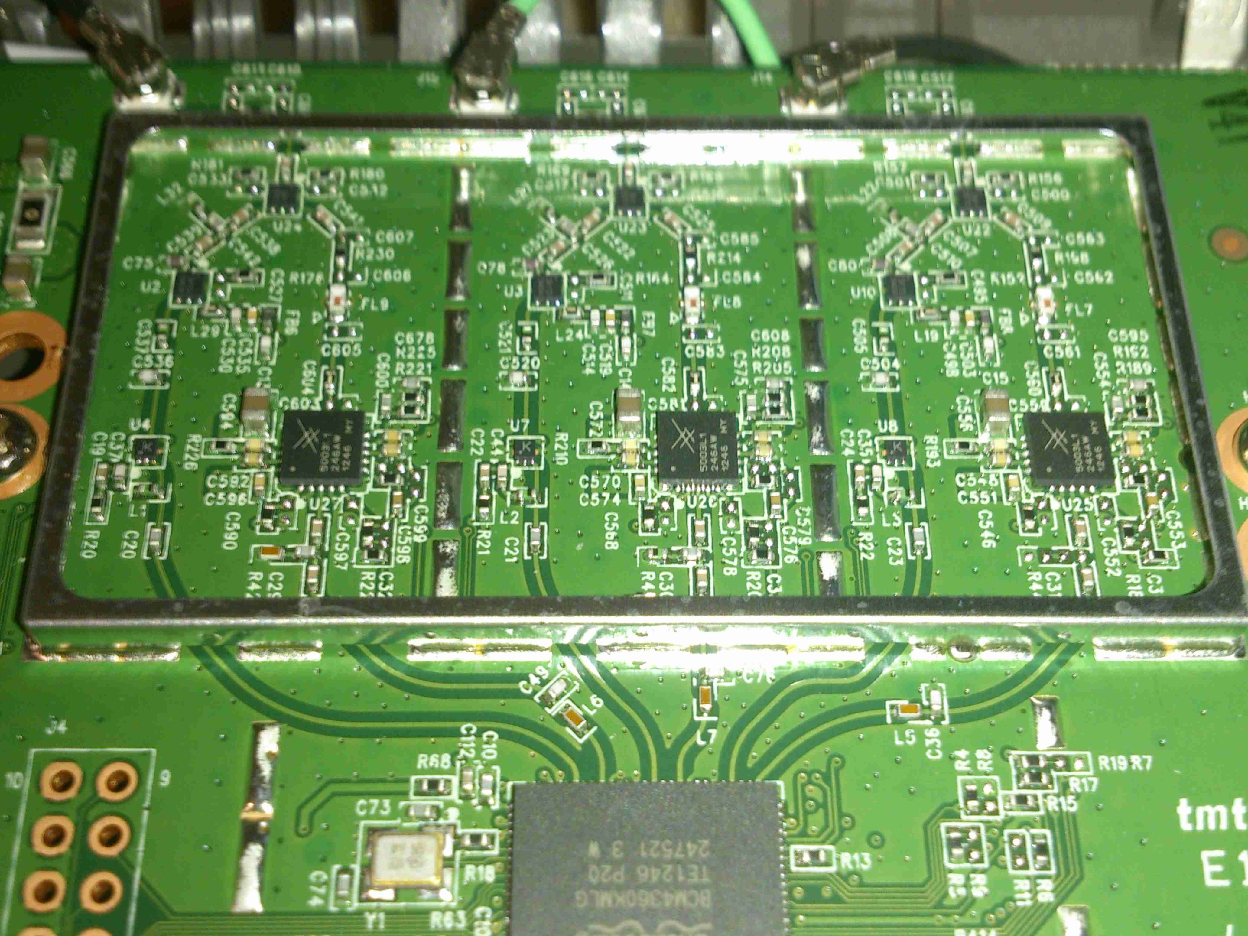
5GHz Power Amplifiers
To get increased range, there are a trio of Skyworks SE5003L +23dBm 5GHz power amplifier ICs under the shield, along with the TX/RX switching & antenna matching networks. Heatsinking for these is provided by a sink screwed to the bottom side of the PCB. The outputs to the antennas can be seen at the top of the image.
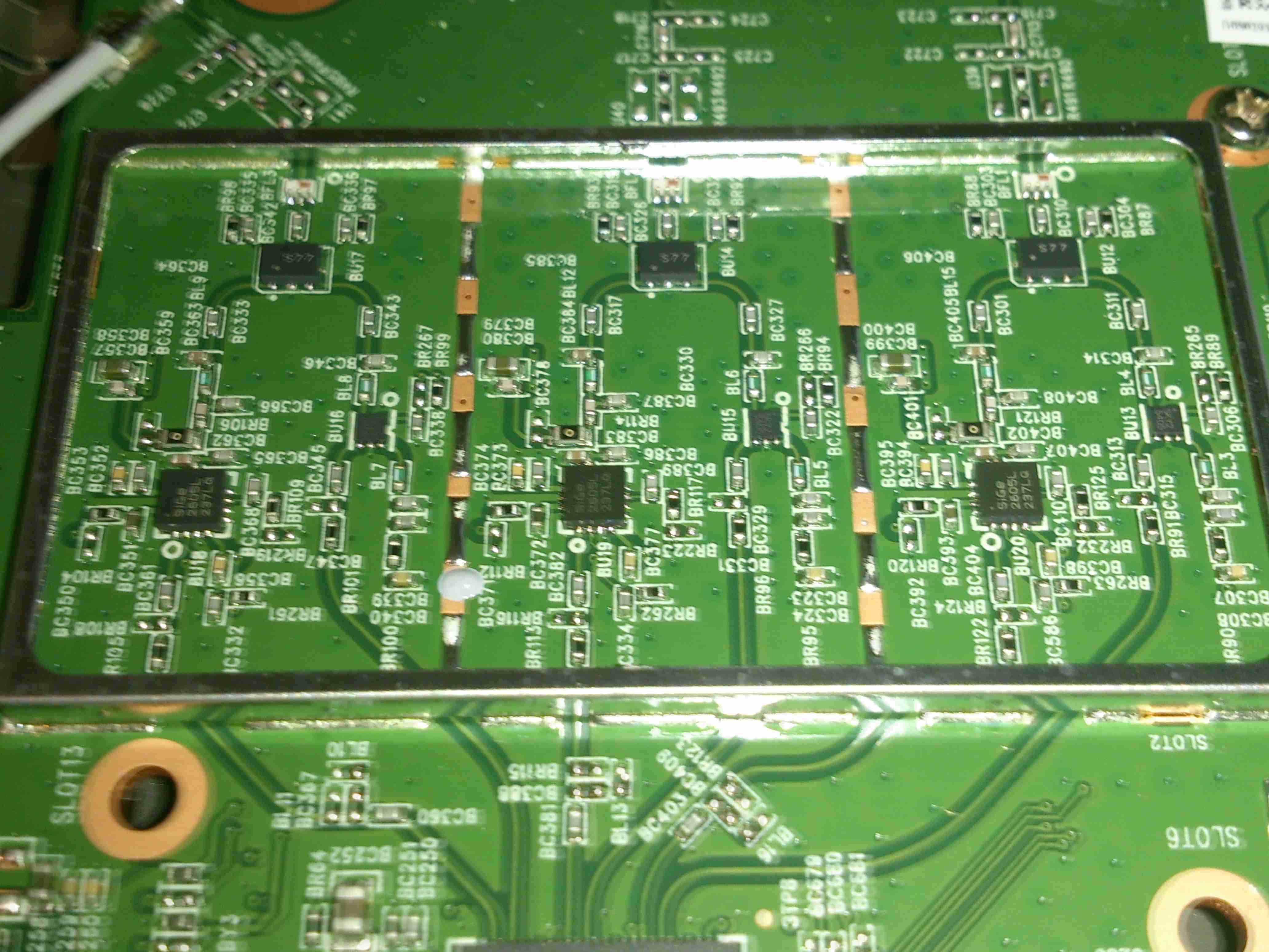
2.4GHz Power Amplifiers
The 2.4GHz section is fitted with a trio of Skyworks SE2605L +23dBm 2.4GHz power amplifiers, with a similar heatsink arrangement under the board. Unlike the 5GHz section, the 2.4GHz antenna feeds are soldered to the PCB here instead of using connectors.
Main CPU
The main CPU is a BCM4708 Communications Processor from Broadcom, as for the other Broadcom chips in this router, very little information is available unless under NDA, but I do know it’s a dual core ARM Cortex A9 running at 1GHz, with built in 5-port gigabit ethernet switch.
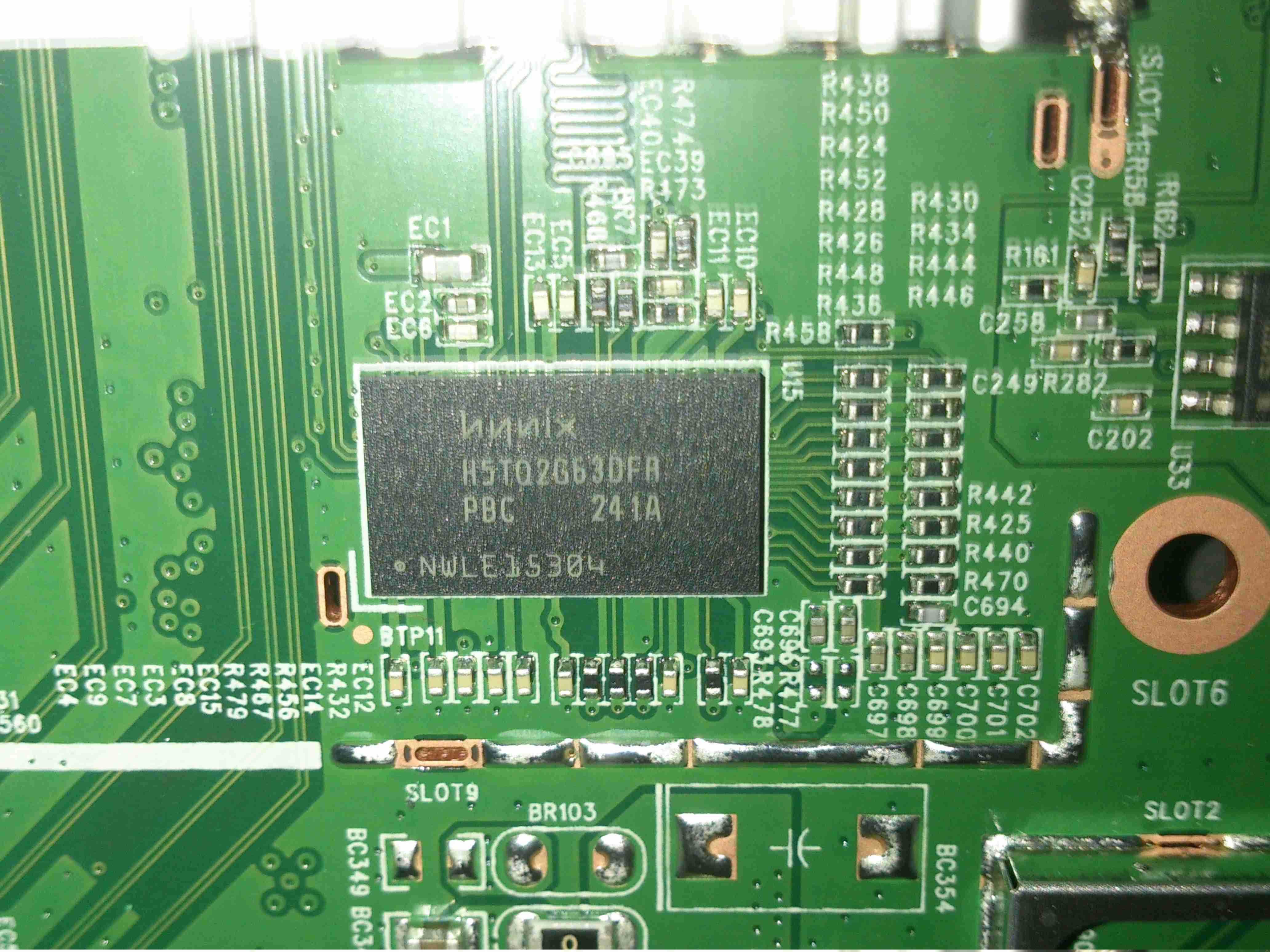
CPU RAM
Working RAM for the processor is a Hynix H5TQ2G63DFA 256MB part.
More to come on the installation of the new networking, with it’s associated 4G mobile gateway connection system.
73s for now!
Tip Jar
If you’ve found my content useful, please consider leaving a donation by clicking the Tip Jar below!
All collected funds go towards new content & the costs of keeping the server online.