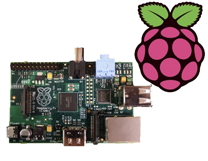
Finally, the Pi has arrived! Currently running the Debian release on a 2GB SD, with some minor modifications.

SSH terminal, running a screen session with a custom status bar.
More updates to come!
Finally, the Pi has arrived! Currently running the Debian release on a 2GB SD, with some minor modifications.
SSH terminal, running a screen session with a custom status bar.
More updates to come!
Well I got my delivery info finally, the week commencing 28/05/2012. Experiments to come once I have it!
Coming soon! Unboxing of the Raspberry Pi & first experiments! Estimated start of June!

Following shipment of another 25x 3W LED modules, the project is restarting.
More details of the power & cooling systems will be posted soon!
More as it happens!

This is the teardown of a Zebra P330i plastic card printer, used for creating ID cards, membership cards, employee cards, etc. I got this as a faulty unit, which I will detail later on.
This printer supports printing on plastic cards from 1-30mils thick, using dye sublimation & thermal transfer type printing methods. Interfaces supplied are USB & Ethernet. The unit also has the capability to be fitted with a mag stripe encoder & a smart card encoder, for extra cost.

On the left here is the print engine open, the blue cartridge on the right is a cleaning unit, using an adhesive roller to remove any dirt from the incoming card stock.
This is extremely important on a dye sublimation based printing engine as any dirt on the cards will cause printing problems.

Here on the right is the card feeder unit, stocked with cards. This can take up to 100 cards from the factory.
The blue lever on the left is used to set the card thickness being used, to prevent misfeeds. There is a rubber gate in the intake port of the printer which is moved by this lever to stop any more than a single card from being fed into the print engine at any one time.

Here is the empty card feeder, showing the rubber conveyor belt. This unit was in fact the problem with the printer, the drive belt from the DC motor under this unit was stripped, preventing the cards from feeding into the printer.

Here is a closeup of the print head assembly. The brown/black stripe along the edge is the row of thin-film heating elements. This is a 300DPI head.

This is under the print head, the black roller on the left is the platen roller, which supports the card during printing. The spool in the center of the picture is the supply spool for the dye ribbon.
In the front of the black bar in the bottom center, is a two-colour sensor, used to locate the ribbon at the start of the Yellow panel to begin printing.

Inside the top cover is the indicator LCD, the back of which is pictured right.
This is a 16×1 character LCD from Hantronix. This unit has a parallel interface.

Front of the LCD, this is white characters on a blue background.

Here is the cover removed from the printer, showing the drive belts powering the drive rollers. There is an identical arrangement on the other side of the print engine running the other rollers at the input side of the engine.

Here the back panel has been removed from the entire print engine, complete with the mains input wiring & RFI filtering.
This unit has excellent build quality, just what is to be expected from a £1,200+ piece of industrial equipment.

The bottom of the print engine, with all the main wiring & PCB removed, showing the main drive motors. The left hand geared motor operates the head lift, the centre motor is a stepper, which operates the main transmission for the cards. The right motor drives the ribbon take up spindle through an O-Ring belt.

Card feeder drive motor, this connects to the belt assembly through a timing belt identical to the roller drive system.
All these DC geared motors are 18v DC, of varying torque ratings.

Here is the main power supply, a universal input switch-mode unit, outputting 24v DC at 3.3A.

PSU info. This is obviously an off the shelf unit, manufactured by Hitek. Model number FUEA240.

The PSU has been removed from the back of the print engine, here is shown the remaining mechanical systems of the printer.

A further closeup of the print engine mechanical bay, the main stepper motor is bottom centre, driving the brass flywheel through another timing belt drive. The O-Ring drive on the right is for the ribbon take up reel, with the final motor driving the plastic cam on the left to raise/lower the print head assembly.
The brass disc at the top is connected through a friction clutch to the ribbon supply reel, which provides tension to keep it taut. The slots in the disc are to sense the speed of the ribbon during printing, which allows the printer to tell if there is no ribbon present or if it has broken.

Here is a further closeup, showing the RFID PCB behind the main transmission. This allows the printer to identify the ribbon fitted as a colour or monochrome.
The antenna is under the brass interrupter disc on the left.

The I/O daughterboard connects to the main CPU board & interfaces all the motors & sensors in the printer.

Here is the main CPU board, which contains all the logic & processing power in the printer.

Main CPU. This is a Freescale Semiconductor part, model number MCF5206FT33A, a ColdFire based 32-bit CPU. Also the system ROM & RAM can be seen on the right hand side of this picture.

Bottom of the Ethernet interface card, this clearly has it’s own RAM, ROM & FPGA. This is due to this component being a full Parallel interface print server.

Top of the PCB, showing the main processor of the print server. This has a ferrite sheet glued to the top, for interference protection.
This is just a few notes on the repair of an eCig battery (1Ah Tornado).
These batteries seem to have a flaw in which they will randomly stop working, while still displaying all the normal activity of the battery.
Here is what I have found.

Here the battery has been partially disassembled, with the control circuitry exposed here at the end of the unit. All the wiring here is fine & the electronics themselves are also OK, due to the LEDs still operating as normal when the button is pushed. The 1000mAh Li-Poly cell is to the right.

Here the end cap has been removed from the opposite end of the battery & the problem is found: the short wire here is the GND return for the atomiser, normally connected to the negative terminal of the battery in the tube, however here it has broken off.
This is most likely due to either the cell moving inside the tube during normal operation, weakening the solder joint, or simply a bad solder job from the factory. (This lead-free ROHS bullshit is to blame).

Here the wire has been successfully soldered back on to the battery tab. I have also added a small dab of hot glue to hold the battery in place on the inside of the tube, & replaced the solder on the joints with real 60/40 leaded solder. £15 saved.

This is the Velleman MK179 Proximity Card Reader, which is supplied in kit form. In the image above you can see the completed kit, the read coil is etched onto the black PCB on the left. Bringing a recognised card close to the coil operates the relay on the main PCB for a programmable amount of time.

Closeup of the main PCB, 12v DC input at top right. Left IC is an LM358 dual Op-Amp, the IC on the right is a PIC12F629 with Velleman’s custom firmware.
Logic power is supplied to the ICs & the oscillator from the LM7805 regulator at the top of the PCB. The relay is a standard 15A SPDT 12v coil relay, with the switch contacts broken out onto the screw terminals on the left.

As it is not provided with the kit, unlike other Velleman kits, here is the schematic for this.

This unit was bought from eBay to experiment with Magnetic Stripe cards, for little money. This unit is capable of reading & writing all 3 tracks, & both Hi-Co & Lo-Co card types.
Interfaced to a PC through USB, this has a built in PL2303 USB-Serial IC & requires 3A at 9v DC to operate.
The 3 Indicator LEDs on the top of the unit can be toggled by the included software for Power/OK/Fault condition signalling.

Bottom of the unit with the model labels.

Closeup of the model label & serial number.

Here the bottom cover has been removed, showing the main PCB. The pair of large ICs bottom center interface with the magnetic heads. The IC above them has had the markings sanded off.

Closeup of the Prolific PL-2303 USB-Serial converter IC.

Here the connections to the R/W heads are visible, current limiting resistors at the left for the write head, a pair of signal relays, a pair of optoisolators & a LM7805 linear voltage regulator.

Here is the trio of indicator LEDs on a small sub-board.

The PCB has been removed from the main frame here, the only component visible is the rotary encoder.

The rotary encoder has a rubber wheel fitted, which reads the speed of the card as it is being swiped for writing. This allows the control logic to write the data to the stripe at the correct rate for the speed of the card. This allows the unit to write cards from 5-50 inches per second speed.
The Write head is directly behind the rubber pressure roller.

Here you can see the R/W head assembly. The write head is on the right, read on the left. When a card is written to, it immediately gets read by the second head for verification.
The drivers for this unit are also available here: Magcard Writer Drivers

This is a standard 13A UK main power plug – with a twist. This one requires no tools to open or connect.
The top cover is slid off the top, after turning the red cam with a coin to unlock it.

Manufactured by Plugco – a Google search of this company returns no results.

Top cover removed from the plug, as is standard with UK mains plugs the live conductor is fused – 3A in this case. The conductors are clamped into the fittings in a row along the top edge of the plug.

Closeup of the wire clamps. Conductor is placed in the slot & snapped closed.
This is an old plug & they do not appear to be available these days, for unknown reasons. Being able to change a plug without a screwdriver has it’s advantages 🙂
Here I will document progress in replacing standard halogen MR10 lights with LEDs.

These units are from TruOpto, available through Rapid Electronics in the UK. They are 3W total, from 3x 1W emitters on an aluminium back plate.

Here is the LED attached to a heatsink for testing purposes – these units dissipate nearly 2W in heat at full output.
As the lights are to be run from a 12v battery bank, for simplicity a master regulator is required to provide a stable 11.4v rail for LED supply.

I have used a Texas Instruments part – PTN78020WAH. This is a 6A capable adjustable regulator module.
The LED lights are to be fully dimmable – the low voltage PWM dimmers are in progress of being built.
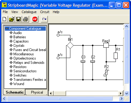
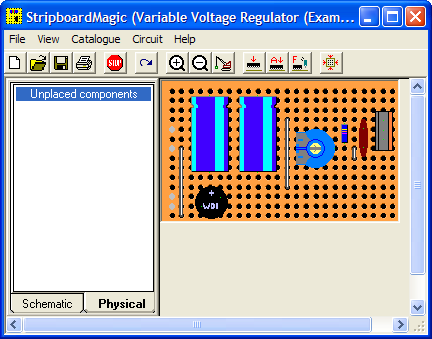
Stripboard Magic is a Windows application for designing PCB layouts on stripboard (aka prototyping board, aka Veroboard). It was released by a British company called Ambyr which ceased trading a long time ago.
The interface is a quite primitive and a little strange but the program is functional even on Windows XP. It also works great under wine in Linux, at least with version 0.9.38 and above as this is all I have checked. It should probably work on older versions too. I haven’t tried it on Vista though.
It can be a handy program when called upon and I have successfully used it a few times when throwing together random small circuits. Due to the interface I would imagine it to be a bit clumsy for very large circuits. The biggest gripe I have with it is the inability to change the orientation of components on the board, so some circuits tend to be slightly larger than they need to be.
I downloaded a copy of Stripboard Magic 1.0 back in the 90’s and recently just found it lying about on my computer. As I would consider it to well and truly be abandonware and as it seems to be a little sought after by some hobbyists I have provided a link to download it below.
Here are some screenshots showing the schematic view (top) and board layout view (bottom):
Another hard to find app these days is Stripboard Designer, mirrored here for people who wish to use it.

Here are the viewfinder electronics from a 1984 Hitachi VHS Movie VM-1200E Camcorder. These small CRT based displays accept composite video as input, plus 5-12v DC for power.

Here is the front face of the CRT, diameter is 0.5″.

Closeup view of the PCB, there are several adjustments & a pair of connectors. Socket in the upper left corner is the power/video input. Pinout is as follows:


Closeup view of the CRT neck, showing the electron gun assembly.

The old CCTV camera used to feed a composite signal to the CRT board. Sanyo VCC-ZM300P.

Connections at the back of the camera. Red & Black pair of wires lead to 12v power supply, Green & Black pair lead to the CRT board’s power pins. Seperate green wire is pushed into the BNC video connector for the video feed. video ground is provided by the PSU’s ground connection.

Finally the connections at the CRT drive board, left to right, +12v, Video, GND.

Display taking video signal from the CCTV camera.

This is a cheap Sigma branded keychain photoframe. User buttons for power & selecting photos are on the left.
There are two white LEDs on the bottom edge that function as a torch as well.

Front of the unit removed, showing the LCD module. The USB jack is bottom left, next to the pair of white LEDs & above that is the 32kHz watch crystal that the CPU uses for timekeeping.

Here the back has been removed showing the 3.7v Li-Ion cell used to provide power.

Here the display has been removed from the PCB exposing the chipset.

Here the CPU blob-top chip & a flash memory IC are visible. The CPU is a Sitronix ST2205U.

Here is an old XM2000 marine VHF tranciever.

Here is the casing split, with the main CPU board & display on the right, & the RF tranciever board on the left.

View of the main CPU board, with the mic & loudspeaker on the right hand side.
The channel display is on the reverse side of the PCB.

View of the RF board, with it’s brass shielding attached. This radio will transmit at 5W max.

Shielding removed, power regulation bottom right corner of the board, tranciever on the left.

CPU board removed from the casing, showing the LCD & the user buttons to the left.

This is a small 120W power inverter, intended for small loads such as lights, fans, small TVs & laptop computers.

End cover of the unit, 12v DC input cord at the top, power switch & indicator LEDs at the bottom.

Opposite end of the unit, with the standard 240v AC 50Hz Mains output socket.

Cover removed from the top of the unit. Main power transformer is visible in the centre here, MOSFET bank is under the steel clamp on the left, the aluminium case forms the heatsink.

On the right is a KA3525 switchmode PWM controller & on the left is a LM324N quad Op-Amp IC. The buzzer on the far left is for the low battery warning.

PCB removed from the casing, with the MOSFET bank on the right hand side. Two potentiometers in the centre of the board tweak the frequency of the switcher & the output voltage.
Reprinted from The Pirate Bay. Thought this deserved as much net coverage as possible.
February 2011, MAFIAA Lobbyists began a massive attack against the European Union.
Defending the union were seeds and peers of The Pirate Bay along with the Telecomix, Anons, and the Pirate parties. The MAFIAA relied on an aggressive battle plan, utilizing modern communications such as radio and telefax to direct troops in the field. The Allies, for their part, assumed a defensive posture, just as they had done at the start of World Internets War of 2003, and in many cases still relied on irc.
As a result, the MAFIAA blitzkrieg caught the Allies off-guard. MAFIAA’s smooth talks and bribes against key players in the EU staged a surprise attack, then turned northward and soon surrounded the bulk of the EU headquarters in Belgium.
After just a few weeks of battle, MAFIAA’s armies had conquered the right, the left and the liberal parties.
I expect that the Battle of Internets is about to begin. Upon this battle depends the survival of an Uncensored civilization! Upon it depends our own free life, and the long continuity of our sites and our trackers. The whole fury and might of the enemy will very soon be turned on us.
MAFIAA knows that they will have to break us in Brussels or lose the war. If we can stand up to them, all Europe may be free and the life of the world may move forward into broad, sunlit uplands. But if we fail, then the whole world, including all that we have known and cared for, will sink into the abyss of a new Dark Age made more sinister, and perhaps more protracted, by the lights of perverted science.
Let us therefore brace ourselves to our duties, and so bear ourselves that if the free internets and its multitude of sites last for a thousand years, citizens will still say, This was their finest hour.
Yours, Winston Bay.
Full news article here.

Here is an old electrochemical type carbon monoxide detector cell, from Monox. Hole in the centre is the inlet for the gas under test.
DO NOT TRY THIS AT HOME! Electrochemical cells contain a substantial amount of sulphuric acid, strong enough to cause burns.
This is a type of fuel cell that instead of being designed to produce power, is designed to produce a current that is precisely related to the amount of the target gas (in this case carbon monoxide) in the atmosphere. Measurement of the current gives a measure of the concentration of carbon monoxide in the atmosphere. Essentially the electrochemical cell consists of a container, 2 electrodes, connection wires and an electrolyte – typically sulfuric acid. Carbon monoxide is oxidized at one electrode to carbon dioxide while oxygen is consumed at the other electrode. For carbon monoxide detection, the electrochemical cell has advantages over other technologies in that it has a highly accurate and linear output to carbon monoxide concentration, requires minimal power as it is operated at room temperature, and has a long lifetime (typically commercial available cells now have lifetimes of 5 years or greater). Until recently, the cost of these cells and concerns about their long term reliability had limited uptake of this technology in the marketplace, although these concerns are now largely overcome. This technology is now the dominant technology in USA and Europe.

Rear of unit with connection pins. Hole here is to let oxygen into the cell which permits the redox reaction to take place in the cell when CO is detected, producing a voltage on the output pins.

Cell disassembled. The semi-permeable membrane on the back cover can be seen here, to allow gas into the cell, but not the liquid electrolyte out. Cell with the electrodes is on the right, immersed in sulphuric acid.

Closeup of the electrode structure. Polymer base with a precious metal coating.

Membrane & filter on the test gas input port.

Here is a Inductive charger designed for the Nintendo DSi. Cheap Chinese build, but it does work!

Top has been removed from the unit here. Most prominent in the centre is a solid steel bar, simply there to give the device some weight.
Pair of Tri-colour LEDs at the front indicates charging status.
Induction coil is on the left, with the controller & oscillator PCB at the top.

Closeup of the PCB, ICs have had their markings ground off.

Induction coil. This couples power into a coil built into a special battery, supplied with the base, to charge it when the DSi is placed on the dock.

Information Label on the base.

Standard DSi charger port, connects to the charger you get with the DSi. Power switch is on the right.
A bit of a shift from my usual content, but I thought this deserved a place for people to see. Only relevant for people of the UK though.
“I’m a DWP worker sticking his head above the parapet and hoping not to get shot…
I work in a busy Jobcentre and my customers are those 25+ who’ve been out of work for 13 weeks or longer. Probably 60-70% of the one hundred or more people I see every week [who] are evidently not fit for work and yet, in theory, it’s my job to whip them through the same hoops as everybody else, persecute them, attempt to stop their benefits and generally shame them into applying for all manner of wholly unsuitable jobs that they’re never going to be able to do.
In reality, what I do is tell them the system sucks and advise them of ways they can stay beneath the radar, or suggest they sign off JSA and move onto ESA and do whatever I can to make the transition as trouble free as possible.
On the other side of the office to me are the Pathways team, who deal with customers on ESA. We all know that over the coming months most of them will be forced to migrate over to the JSA bods like myself and we won’t be able to cope with either the numbers or the particular problems that this customer group represents.
The point of all this waffle is that the policy makers have embarked upon their catastrophic journey without consulting the frontline workers who, without exception in my experience, KNOW that the planned changes CANNOT work.
I would advise people worried about a forced transition from ESA to JSA to be brave and try not to lose too much sleep about it… It’s just not do-able in the real world, there’ll be a horrible mess and people’s lives will face some awful but shortlived disruption and then it’ll be business as usual.
Also, for those who face the indignity of having to venture into a jobcentre from time to time, please be assured – the majority of those who work in them are actually on your side, and have probably less faith in our political masters than you do, and just as much awareness as yourselves that all their vitriolic guff about benefit scroungers and feckless layabouts is simply empty, venomous scapegoating…”
Please feel free to copy and paste this to your own notes/blog, etc. Spread the truth.

Here is a label maker, bought on offer at Maplin Electronics. Full Qwerty keyboard with 1 line dot matrix LCD display visible here. Power is 4 AAA cells or a 6v DC Adaptor.

Rear cover removed. Battery compartment is on the left hand side, space for the tape cartridge on the right. Ribbon cable leading to the thermal print head is on the far right, with rubber tape drive roller.

PCB under the top cover with the main CPU, a MN101C77CBM from Panasonic. This CPU features 48K Mask ROM & 3K of RAM. Max clock frequency is 20MHz. 32kHz clock crystal visible underneath a Rohm BA6220 Electronic speed controller IC.
This is used to drive the printer motor at a constant accurate speed, to feed the tape past the thermal head. Miniature potentiometer adjusts speed.
Ribbon cable at the bottom of the board connects to the print head, various wiring at the left connects to the battery & DC Jack.

Printer drive mechanism. Small DC motor drives the pinch roller though a gear train. DC Jack & reverse polarity protection diode is on the right.
This unit uses a centre negative DC jack, which is unusual.

Thermal tape cartridge, black text on white background.

Here is an old type KVM switch, PS/2 & VGA interface.

Details Label

Top removed from the main body, the cables coming in from the bottom connect to the VGA, keyboard & mouse ports on the slave computers, the connectors at the top connect to the single monitor, keyboard & mouse.

PCB removed from the body. This is driven by a PIC16C57C-04 microcontroller.
The pair of LEDs indicate which computer is using the peripherals at any one time.

Here is a cheap USB 8-in-1 card reader. Power & Access LEDs are on top left.

Top of the PCB. The OTi IC is the interface IC to the USB port, part number is OTI002126. Card sockets on the top here are CF/Microdrive & Memory Stick.

Bottom of the PCB with the SD/MMC, Smart Media

Cheap old style ball mouse. PS/2 interface.

Top removed from the mouse, the ball fits in the gap in the centre. The slotted discs are visible which contact the ball & move relative to the surface the mouse is on.

PCB removed from the shell. Pairs of IR LEDs & Phototransistors make rotary encoders with the slotted discs. The microswitches read the mouse buttons & wheel.
IC in the centre interfaces with the PC over a PS/2 connection.