Posted on Leave a comment

555 Flyback Driver

Flyback Secondary Waveform
Board Layout
Board Layout

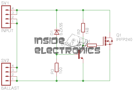
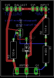
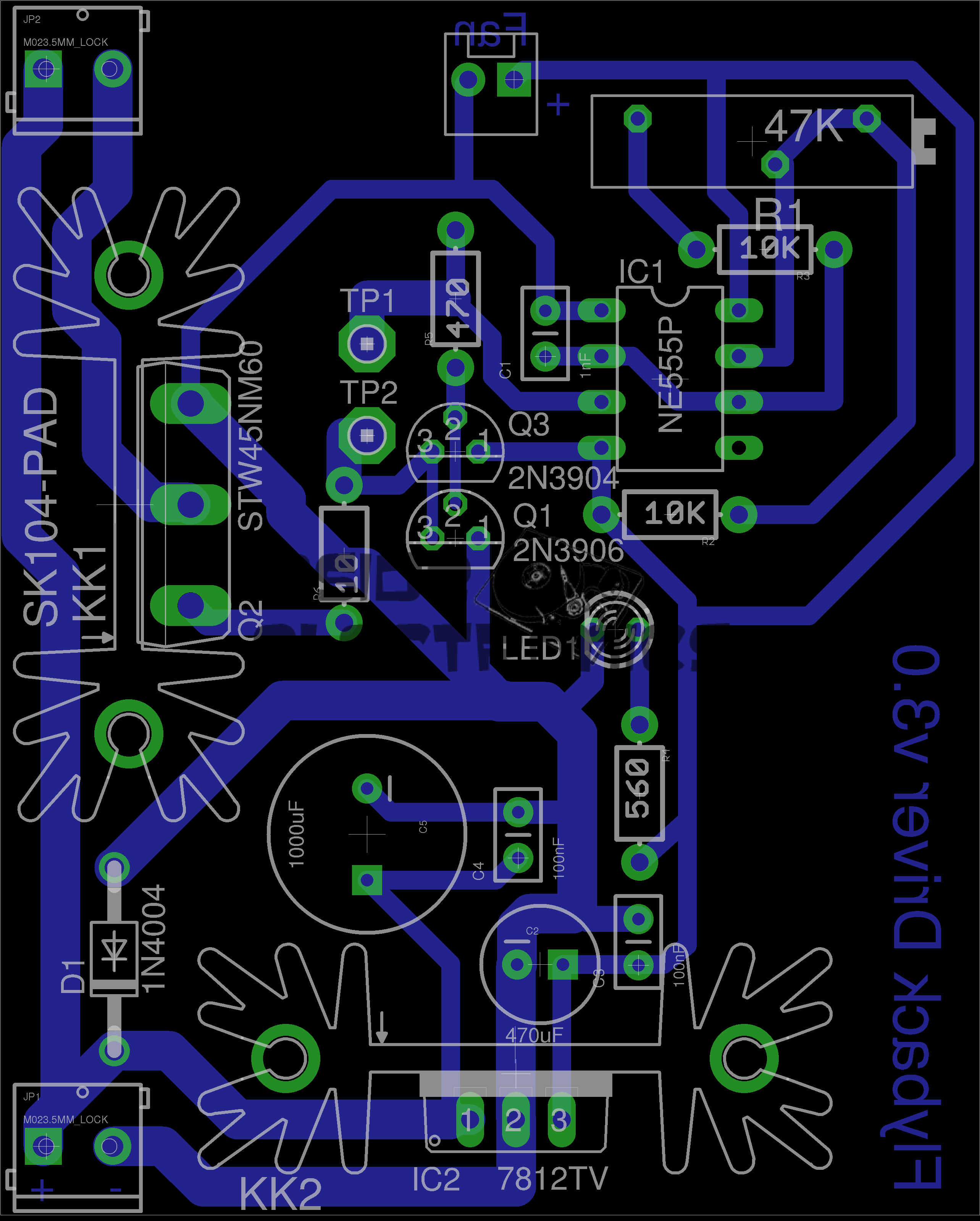
Here is a simple 555 timer based flyback transformer driver, with the PCB designed by myself for some HV experiments. Above is the Eagle CAD board layout.

The 555 timer is in astable mode, generating a frequency from about 22kHz to 55kHz, depending on the position of the potentiometer. The variable frequency is to allow the circuit to be tuned to the resonant frequency of the flyback transformer in use.

This is switched through a pair of buffer transistors into a large STW45NM60 MOSFET, rated at 650v 45A.

Input power is 15-30v DC, as the oscillator circuit is fed from an independent LM7812 linear supply.

Provision is also made on the PCB for attaching a 12v fan to cool the MOSFET & linear regulator.

Initial Board
Initial Board

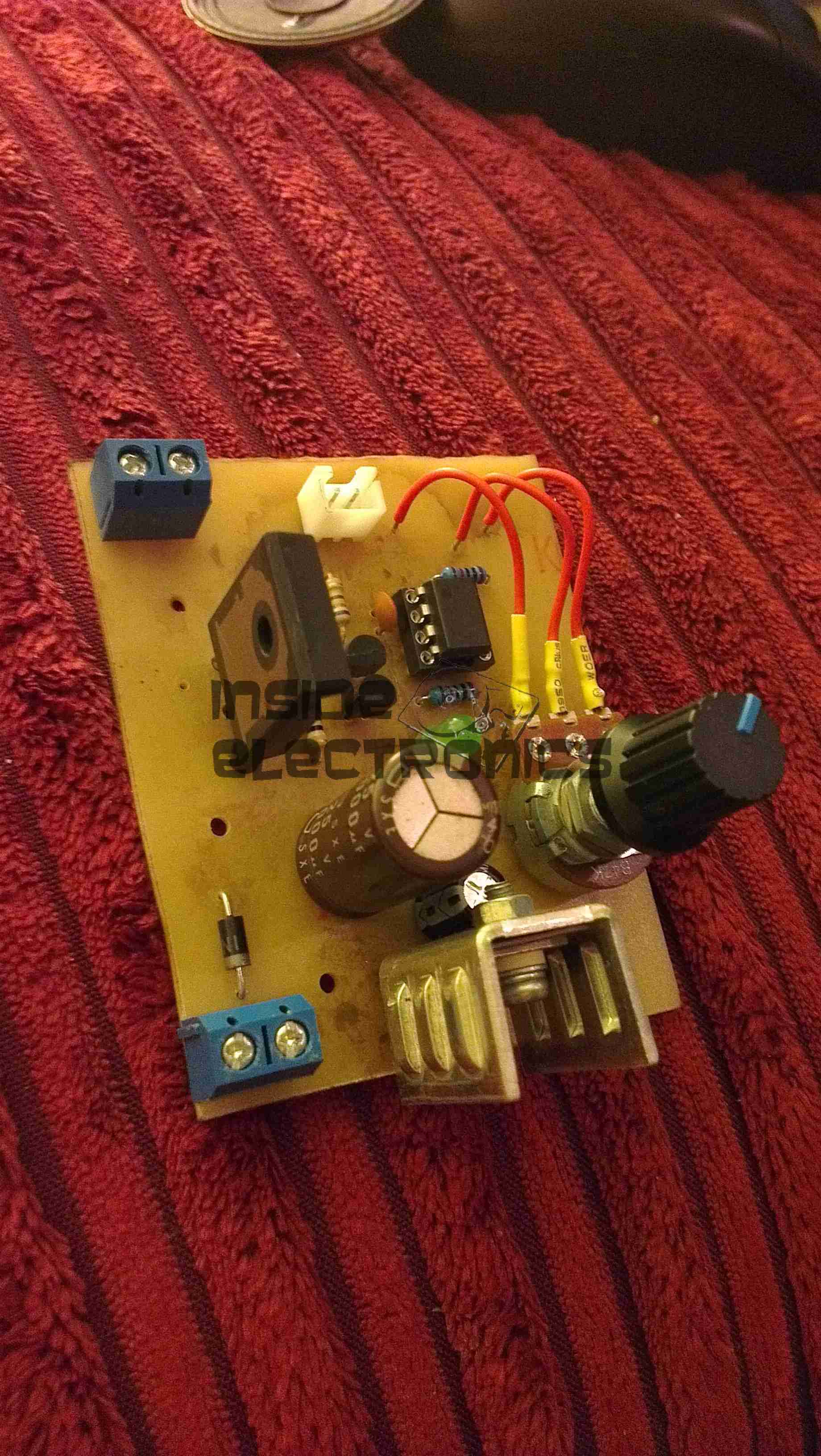
Board initially built, with the heatsink on the linear regulator fitted. I used a panel mount potentiometer in this case as I had no multiturn 47K pots in stock.

PCB Traces
PCB Traces

Bottom of the PCB. The main current carrying traces have been bulked up with copper wire to help carry the potentially high currents on the MOSFET while driving a large transformer.
This board was etched using the no-peel toner transfer method, using parchement paper as the transfer medium.

MOSFET Heatsinked
MOSFET Heatsinked

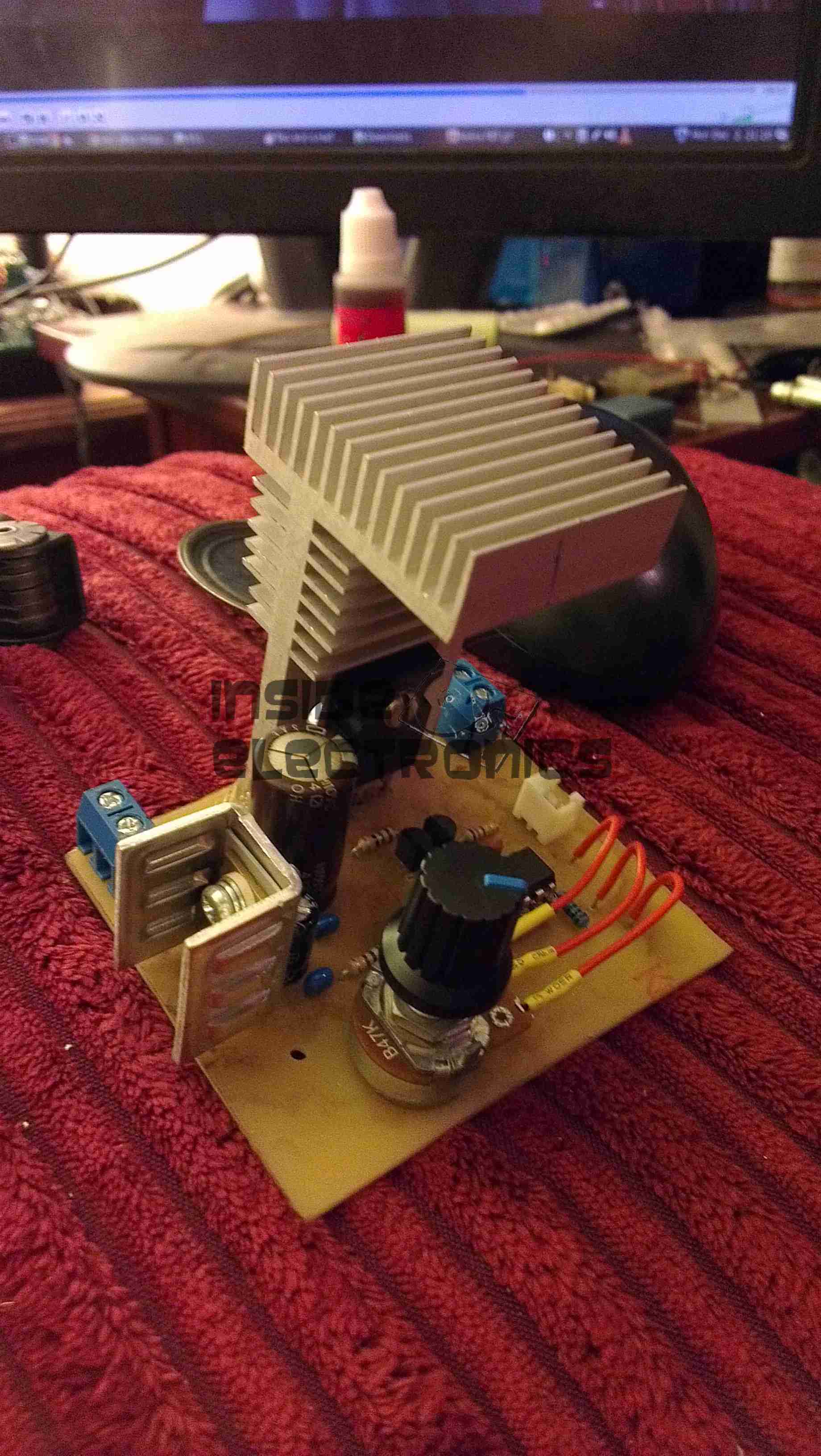
Main MOSFET now fitted with a surplus heatsink from an old switchmode power supply. A Fan could be fitted to the top of this sink to cope with higher power levels.

Gate Drive Waveform
Gate Drive Waveform

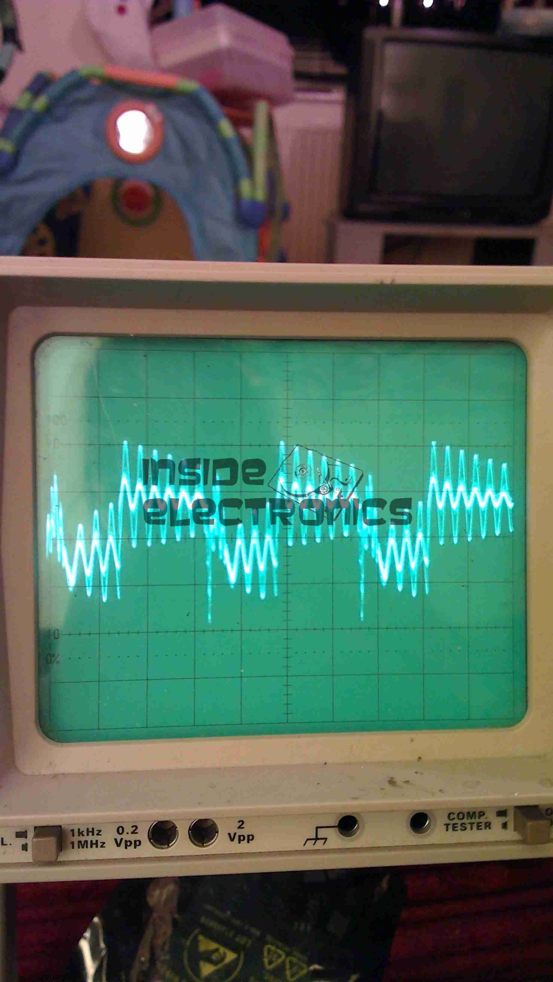
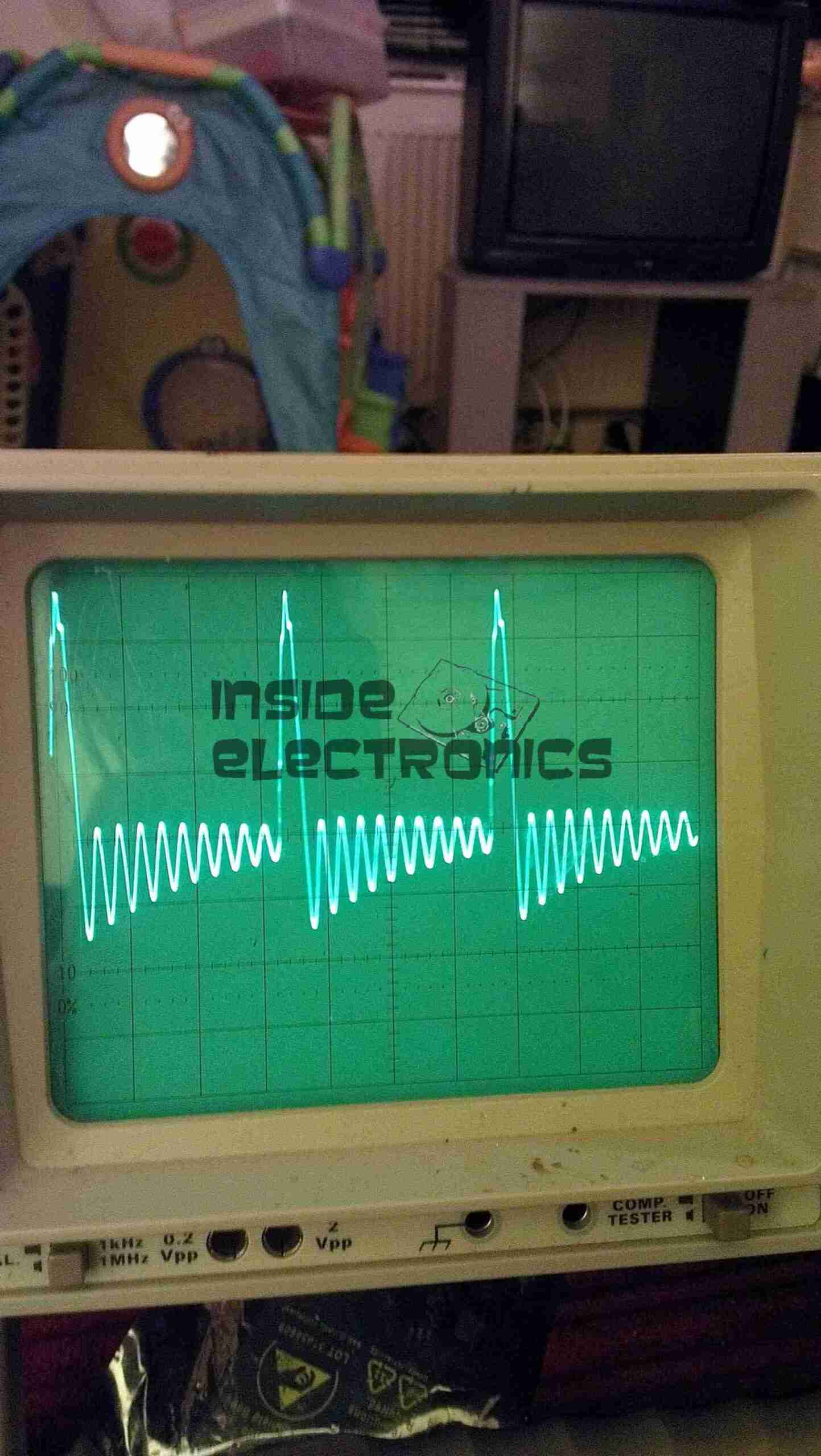
This is the gate drive waveform while a transformer is connected, the primary is causing some ringing on the oscillator. The waveform without an attached load is a much cleaner square wave.

Flyback Secondary Waveform

I obtained a waveform of the flyback secondary output by capacitively coupling the oscilloscope probe through the insulation of the HT wire. The pulses of HV can be seen with the decaying ringing of the transformer between cycles.

Corona Discharge
Corona Discharge
Arc Discharge
Arc Discharge

Corona & arc discharges at 12v input voltage.

Download the Eagle schematic files here: [download id=”5561″]

Posted on Leave a comment

Mobile Power Pack Upgrade

New Regulators
New Regulators

The original LM2577 based regulators I designed into my mobile battery pack turned out to be insufficient for requirements, therefore they have been replaced with higher capacity regulators.

The 12v regulator (left) is a muRata UQQ-12/8-Q12P-C SEPIC converter, providing a max of 8A at 12.1v DC. The 12v rail is also now independently switchable to save power when not in use.

The 5v regulator (right) is a Texas Instruments PTN78020WAZ switching regulator, rated at 6A. The pair of resistors on the back of the regulator set the output voltage to 5.1v.

Also a new addition is a pair of banana sockets & a 2.1mm DC jack, wired into the 12v DC bus, for powering various accessories.

New Additions
New Additions

Below the USB sockets is now a built in eCig charger, to save on USB ports while charging these devices.

IWA National Festival 2013

These changes were made after much field testing of the unit at Cassiobury Park, Watford, for the IWA National Waterways Festival.

Posted on Leave a comment

Wearable Raspberry Pi – Solar Charging


24W Solar Panel
24W Solar Panel

I have acquired a 24W monocrystalline solar panel to charge my portable battery pack while on the move. This panel will be able to charge all devices I carry on a regular basis with nothing but some sunlight!

Info Panel
Info Panel

Info on the panel itself. Rated at 24W with nominal 17.6v DC, 1.36A output.

Regulator
Regulator

I have installed a switching regulator in the back of the panel, where the connections would normally be wired straight to the array of cells. This regulates the voltage down to a constant 13.8v to provide more compatibility with 12v charging equipment. I have tested the output of the panel in late day sun, at 1.27A.


Posted on 1 Comment

FE-5680A Rubidium Frequency Standard – Initial Teardown

Physics Package
Physics Package

Here is a quick look inside the FE-5060A Rubidium Frequency Standard. Above you can see the entire physics package, with the rubidium lamp housing on the right hand side. The ribbon cable running into the resonator cavity has the power & signal traces for the internal heater, temperature sensor & Helmholtz coil.

Lamp End
Lamp End

Here is the lamp end of the physics package, with the voltage regulator & RF driver for the lamp. The FETs soldered to the back of the housing are being used as heaters to maintain a constant temperature on the lamp in operation.
The temperature sensor can be seen between the two FETs, with a single copper wire running around the housing to connect to it.

Main frequency synth board. This contains the RS-232 interface & the AD9830A from Analog Devices. This IC is a direct digital synthesizer & waveform generator.


Synthesizer Board
Synthesizer Board
Posted on Leave a comment

Ultracapacitor Charge Balancing

Balancer
Balancer

I have finally  got round to designing the balancing circuitry for my ultracapacitor banks, which have a total voltage of 15v when fully charged. The 2600F capacitors have a max working voltage of 2.5v each, so to ensure reliable operation, balancing is required to make sure that each capacitor is charged fully.

The circuit above is a simple shunt regulator, which uses a 2.2v zener diode to regulate the voltage across the capacitor.

A 10W 1Ω resistor is connected to the BALLAST header, while the capacitor is connected across the INPUT. Once the voltage on the capacitor reaches 2.6v, the MOSFET begins to conduct, the 1Ω resistor limiting current to ~2.6A.

Each capacitor in the series string requires one of these connected across it.

PCB
PCB

Below is a link to the Eagle project archive for this. Includes schematic, board & gerber files.

[download id=”5555″]

Posted on Leave a comment

Wearable Raspberry Pi Part 2 – Power Supply

All Fitted
All Fitted

Progress is finally starting on the power supply unit for the Pi, fitted into the same case style as the Pi itself, this is an 8Ah Li-Poly battery pack with built in voltage regulation.

Regulator Boards
Regulator Boards

Here are the regulators, fixed to the top of the enclosure. These provide the 12v & 5v power rails for the Pi unit, at a max 3A per rail.

Battery Pack
Battery Pack

In the main body of the case the battery pack is fitted. This is made up of 4 3-cell Li-Poly RC battery packs, rated at 2Ah each. All wired in parallel this will provide a total of 8Ah at 12.6v when fully charged.

Powered Up
Powered Up

Here the regulators are powered up from a 13v supply for testing. I have discovered at full load these modules have very bad ripple, so I will be adding extra smoothing capacitors to the power rails to compensate for this.

I/O
I/O

Here are the connectors on the top of the unit, outputting the two power rails to the Pi & the DC barrel jack that will be used to charge the pack.


Posted on Leave a comment

2600 Farad Ultra Capacitors

Ultracap Bank
Ultracap Bank

Just a quickie to note down the current progress of another project – Ultracapacitors.
Pictured right is a bank of 6 2.5v 2600F Maxwell Boostcaps, for a total of 15v at 433.333F. A total energy storage of  48.7kJ.

Coming soon will be the inclusion of charge balancing, using Zener diodes & integrating a DC-DC converter on the output to hold the bank voltage at 12v when being used.

Posted on 1 Comment

MSR605 3-Track Magnetic Stripe Writer

MSR605
MSR605

This unit was bought from eBay to experiment with Magnetic Stripe cards, for little money. This unit is capable of reading & writing all 3 tracks, & both Hi-Co & Lo-Co card types.
Interfaced to a PC through USB, this has a built in PL2303 USB-Serial IC & requires 3A at 9v DC to operate.
The 3 Indicator LEDs on the top of the unit can be toggled by the included software for Power/OK/Fault condition signalling.

Unit Bottom
Unit Bottom

Bottom of the unit with the model labels.

Model Label
Model Label

Closeup of the model label & serial number.

PCB Bottom
PCB Bottom

Here the bottom cover has been removed, showing the main PCB. The pair of large ICs bottom center interface with the magnetic heads. The IC above them has had the markings sanded off.

USB-Serial Interface

Closeup of the Prolific PL-2303 USB-Serial converter IC.

PCB Top
PCB Top

Here the connections to the R/W heads are visible, current limiting resistors at the left for the write head, a pair of signal relays, a pair of optoisolators & a LM7805 linear voltage regulator.

LEDs
LEDs

Here is the trio of indicator LEDs on a small sub-board.

Frame Bottom
Frame Bottom

The PCB has been removed from the main frame here, the only component visible is the rotary encoder.

Rotary Encoder
Rotary Encoder

The rotary encoder has a rubber wheel fitted, which reads the speed of the card as it is being swiped for writing. This allows the control logic to write the data to the stripe at the correct rate for the speed of the card. This allows the unit to write cards from 5-50 inches per second speed.
The Write head is directly behind the rubber pressure roller.

Read/Write Heads
Read/Write Heads

Here you can see the R/W head assembly. The write head is on the right, read on the left. When a card is written to, it immediately gets read by the second head for verification.

The drivers for this unit are also available here: Magcard Writer Drivers

Posted on Leave a comment

PSi 150 Power Inverter

Front
Front

This is a small 120W power inverter, intended for small loads such as lights, fans, small TVs & laptop computers.

End Cover
End Cover

End cover of the unit, 12v DC input cord at the top, power switch & indicator LEDs at the bottom.

Mains Output
Mains Output

Opposite end of the unit, with the standard 240v AC 50Hz Mains output socket.

Cover Removed
Cover Removed

Cover removed from the top of the unit. Main power transformer is visible in the centre here, MOSFET bank is under the steel clamp on the left, the aluminium case forms the heatsink.

PWM Controllers
PWM Controllers

On the right is a KA3525 switchmode PWM controller & on the left is a LM324N quad Op-Amp IC. The buzzer on the far left is for the low battery warning.

PCB Removed
PCB Removed

PCB removed from the casing, with the MOSFET bank on the right hand side. Two potentiometers in the centre of the board tweak the frequency of the switcher & the output voltage.


Posted on 7 Comments

Monox Compact-S CO Sensor Cell

Top
Top

Here is an old electrochemical type carbon monoxide detector cell, from Monox. Hole in the centre is the inlet for the gas under test.
DO NOT TRY THIS AT HOME! Electrochemical cells contain a substantial amount of sulphuric acid, strong enough to cause burns.

This is a type of fuel cell that instead of being designed to produce power, is designed to produce a current that is precisely related to the amount of the target gas (in this case carbon monoxide) in the atmosphere. Measurement of the current gives a measure of the concentration of carbon monoxide in the atmosphere. Essentially the electrochemical cell consists of a container, 2 electrodes, connection wires and an electrolyte – typically sulfuric acid. Carbon monoxide is oxidized at one electrode to carbon dioxide while oxygen is consumed at the other electrode. For carbon monoxide detection, the electrochemical cell has advantages over other technologies in that it has a highly accurate and linear output to carbon monoxide concentration, requires minimal power as it is operated at room temperature, and has a long lifetime (typically commercial available cells now have lifetimes of 5 years or greater). Until recently, the cost of these cells and concerns about their long term reliability had limited uptake of this technology in the marketplace, although these concerns are now largely overcome. This technology is now the dominant technology in USA and Europe.

Rear
Rear

Rear of unit with connection pins. Hole here is to let oxygen into the cell which permits the redox reaction to take place in the cell when CO is detected, producing a voltage on the output pins.

Disassembled
Disassembled

Cell disassembled. The semi-permeable membrane on the back cover can be seen here, to allow gas into the cell, but not the liquid electrolyte out. Cell with the electrodes is on the right, immersed in sulphuric acid.

Platinum Electrode
Platinum Electrode

Closeup of the electrode structure. Polymer base with a precious metal coating.

Membrane
Membrane

Membrane & filter on the test gas input port.

Posted on 1 Comment

Combo Microwave

Electronics Bay
Electronics Bay

Here are the internals of a cheap Microwave/Convection Oven combo. Electronics bay is pretty much the same as a standard microwave, with the magnetron, transformer & diode/capacitor voltage doubler, with the addition of an extra fan & a pair of nichrome elements to provide the convection oven function.

Convection Fan
Convection Fan

Convection blower which keeps the cooking vapours & smoke away from the elements, & circulates the hot air around the cooking chamber. This is a 12v DC centrifugal type blower.

Convection Element
Convection Element

The elements are inside this steel shield, air duct extends from the centre.

Thermal Cutouts
Thermal Cutouts

This oven has a pair of thermal switches on the magnetron.

Capacitor & Diode
Capacitor & Diode

The usual capacitor/diode voltage doubler in the magnetron power supply. The transformer is visible to the left.

Controller
Controller

Electronic controller PCB. This has a pair of relays that switch the elements & the magnetron transformer.

Posted on Leave a comment

Belling Microwave


Front
Front

Here is a cheap no frills microwave oven, which died after a few weeks of normal use.

Electronics Bay
Electronics Bay

Cover removed, showing the internals. Front of the microwave is on the left.

Timer
Timer

Closeup of the timer unit. Cheap & nasty.

Magnetron
Magnetron

Magnetron removed from the oven. Antenna is on the top,  cooling fins visible in the center. White conector at the bottom is the filament terminals.

Magnetron Chokes
Magnetron Chokes

Chokes on the magnetron’s filament connections. These prevent microwave energy from feeding back into the electronics bay through the connections.

Magnetron Assembly
Magnetron Assembly

Magnetron cooling fins, tube & magnets removed from the frame.

Magnetron Tube
Magnetron Tube

Bare magnetron tube.

Power Input Board
Power Input Board

This PCB does some rudimentary power conditioning, power resistors are in series with the live feed to the power trasformer, to prevent huge power up surge. When the transformer energizes the relay, which is in parallel with the resistors, switches them out a fraction of a second after, providing full power to the transformer.
Standard RFI choke & capacitor at the top of the board, with the input resistor.

Transformer
Transformer

Power transformer to supply the magnetron with high voltage.
Power output is ~2kV at ~0.5A. Pair of spade terminals are the low voltage filament winding.

Capacitor
Capacitor

HV Capacitor. This along with the diode form a voltage doubler, to provide the magnetron with ~4kV DC.

Diode
Diode

HV diode stack.

Fuse Element
Fuse Element

Internals of the HV fuse. Rated for ~0.75A at 5kV. The fuse element is barely visible attached to the end of the spring. Connects between the transformer & the capacitor.

Cooling Fan
Cooling Fan

Cooling fan for the magnetron. Drive is cheap shaded pole motor.

Fan Motor
Fan Motor

Fan motor. Basic 240v shaded pole induction type.

Posted on Leave a comment

Power Pack Regulator Update

7.5v Regulator
7.5v Regulator

To help make my system more efficient, a pair of switching regulators has been fitted, the one shown above is a Texas Instruments PTN78060 switchmode regulator module, which provides a 7.5v rail from the main 12v battery pack.

A Lot like the LM317 & similar linear regulators, these modules require a single program resistor to set the output voltage, but are much more efficient, around the 94% mark at the settings used here.

The 7.5v rail supplies the LM317 constant current circuit in the laser diode driver subsection. This increases efficiency by taking some voltage drop away from the LM317.

5v Regulator
5v Regulator

The 7.5v rail also provides power to this Texas Instruments  PTH08000 switchmode regulator module, providing the 5v rail for the USB port power.

Posted on 2 Comments

Epson Ink Cartridge Resetter

Interface
Interface

This is a device designed to reset Epson brand ink cartridges that are reportedly out of ink, so they again report full to the printer Here is the front of the unit, with the guide for attaching to a cartridge.

PCB Back
PCB Back

Back of the device removed. 3 button cells provide power to the PCB. Indicator LED sticks out of the top of the device for reset confirmation.
Row of pads on far left edge of the PCB are presumably a programming header for the uC on the other side of the board.

PCB Front
PCB Front

Here is the  front of the PCB, main feature being the grid of pogo pins to connect to the cartridge chip. IC on lower right of that is a MSP430F2131 uController, a Texas Instruments part.
The IC directly to the left of the pogo pin bed is a voltage regulator, to step down the ~4.5v of the batteries down to the ~3.3v that the uC requires.

Posted on Leave a comment

Nokia 7110

Front
Front

Another phone from the mid 90s. This is the nokia 7110.

Slider Open
Slider Open

Here the slider is open showing the keypad.

Battery Removed
Battery Removed

Here the battery is removed, a Li-Ion unit.

Battery
Battery

The battery cell & protection circuit removed from the casing.

Rear Of PCB
Rear Of PCB

This is the rear of the PCB removed from the housing. Data & charging ports on the right hand side f the board.

Front Of PCB
Front Of PCB

Front of the PCB with the RF sections at the left hand side & the keypad contacts on the right.

RF Sections
RF Sections

Closeup of the RF sections of the board, big silver rectangular cans are VCO units.

SIM Connector
SIM Connector

Closeup of the top rear section of the PCB, with SIM cnnector, battery contacts, IR tranciever at the far left. Bottom centre is the external antenna connector.

CPU
CPU

The logic section of the board, Large chip is CPU, to right of that is the ROM storing the machine code. Other chips are unknown custom parts.

Mic & Speaker
Mic & Speaker

The Mic & the loudspeaker removed from it’s housing.

LCD
LCD

LCD from the front of the unit, SPI interfaced. Flex PCB also contains the power button, loudspeaker contacts & a temperature sensor.

Scroll Wheel
Scroll Wheel

The scroll wheel removed from the front housing.

Vibra-Motor
Vibra-Motor

Tiny vibration motor removed from the rear housing, alerts the user to a text or phone call.

Posted on Leave a comment

ICL Barcode Scanner

Top
Top

An ICL barcode scanner from the 80s is shown here. This is the top of the unit with cover on.

Cover Removed
Cover Removed

Plastic cover removed from the unit showing internal components. Main PSU on left, scan assembly in center. Laser PSU & Cooling fan on right. Laser tube at top.

Scan Motor
Scan Motor

Closeup of laser scan motor. This unit scans the laser beam rapidly across the glass plate to read the barcode.

Controller PCB
Controller PCB

View of the bottom of the unit, showing the controller PCB in the centre.

Scan Motor Driver
Scan Motor Driver

The 3-phase motor driver circuit for the scan motor. 15v DC powered.

Laser Unit
Laser Unit

This is the laser unit disconnected from the back of the scanner. HT PSU is on right hand side, beam emerges from optics on left.

Laser Unit Label
Laser Unit Label

This unit is date stamped 1987. The oldest laser unit i own.

Tube PSU
Tube PSU

Laser tube power supply. Input voltage: 24v DC. Output: 1.8kV 4mA.

Laser PSU Board
Laser PSU Board

Rear of HT PSU. Obviously the factory made a mistake or two 🙂

Laser Tube Mounting
Laser Tube Mounting

Top cover removed from the laser unit here shows the 1mW He-Ne tube. Manufactured by Aerotech.

Tube Label
AeroTech He-Ne Tube

Tube label. Manufactured July 1993. Model LT06XR.

Plasma
Plasma

Here the tube has been removed from it’s mount to show the bore down the centre while energized.

OC Mirror
OC Mirror

OC end of the tube shown here lasing.

Beam
Beam

Beam output from the optics on the laser unit.

Tube Optics
Tube Optics

Optics built into the laser unit. Simple turning mirror on adjustable mount & collimating lens assembly.

Scan Lines
Scan Lines

Kind of hard to see but the unit is running here & projecting the scan lines on the top glass.

Laser Tube Mounting
Laser Tube Mounting

Laser tube mounting. A combo of spring clips & hot glue hold this He-Ne tube in place

Posted on Leave a comment

Hair Dryer

Housing
Housing

This is a 1500W hairdryer, death caused by thermal switch failure.

Switch
Switch

This is the switch unit. Attached are two suppression capacitors & a blocking diode. Cold switch is on right.

Heating Element
Heating Element

Heating element unit removed from housing. Coils of Nichrome wire heat the air passing through the dryer. Fan unit is on right.

Thermal Switch
Thermal Switch

Other side of the heating element unit, here can be seen the thermal switch behind the element winding. (Black square object).

Fan Motor
Fan Motor

The fan motor in this dryer is a low voltage DC unit, powered through a resistor formed by part of the heating element to drop the voltage to around 12-24v. Mounted on the back of the motor here is a rectifier assembly. Guide vanes are visible around the motor, to straighten the airflow from the fan blades.

Fan
Fan

5-blade fan forces air through the element at high speed. Designed to rotate at around 13,000RPM.