HeNe Laser Wavelengths
While what comes to mind when there is mention of a HeNe laser is a red beam, those with other wavelengths are manufactured.
- The most common HeNe lasers by far produce light at a wavelength of 632.8 nm in the red part of the visible spectrum. This is well into the region of the human eye’s high sensitivity (but not anywhre as good as green). Thus, a 1 mW red HeNe laser will appear brighter than a 4 mW diode laser operating at 670 nm. Although these are called red HeNe lasers, compared to the color of the 670 nm diode, their beam actually appears somewhat orange-red.
- Green (543.5 nm), yellow (594.1 nm), and orange (604.6 and 611.9 nm) HeNe lasers are also available but are not nearly as ‘efficient’ as the common red type since the spectral lines that need to be amplified are much weaker at these wavelengths. Thus, ‘other color’ HeNe lasers must be much larger for the same output power and use higher quality mirrors. Manufacturing yield is also lower and far fewer of these are produced. Taken together, the bottom line is that they are much more expensive either new or surplus.Note: Since the gain of these wavelengths is so low, they also have a shorter life and the chance of finding working surplus green or yellow HeNe lasers is much lower than for red. I would not recommend bidding on an eBay auction for one of these unless guaranteed to be working. The likelihood of the problem for an “unknown condition” green or yellow HeNe laser being just mirror alignment is small to none!
- IR (infra-red) HeNe laser tubes are manufactured as well (1,523.1 nm is most common probably because this wavelength is useful for testing of fiber optic data transmission systems). The other two common IR wavelengths are 1,152.3 and 3,391.3 nm. However, an invisible beam just doesn’t seem as exciting and these make truly lousy laser pointers!
Typical maximum output available from (relatively) small HeNe tubes (400 to 500 mm length) for various colors: red – 10 mW, orange – 3 mW, yellow – 2 mW, green – 1.5 mW, IR – 1 mW. Higher power red HeNe tubes (up to 35 mW or more and over 1 meter long) and ‘other-color’ HeNe tubes (much lower – under 10 mW) are also available. However, these will be very large and very expensive.
Tunable HeNe Lasers
If it were possible to select any available wavelength desired, then some people would be content beyond description. 🙂
A few tunable HeNe lasers have been produced commercially. These provide wavelength (color) selection with the turn of a knob. However, due to the low gain of most HeNe lasing lines, producing a useful tunable HeNe laser is not an easy task. Everything must be just about perfect to get the “other color” lines to lase at all, and even more so when a laser is to be designed to work at more than one wavelength with a TEM00 beam. The most widely known such laser (as these things go) is manufactured by Research Electro-Optics, Inc. (REO). It produces at least 5 of the visible wavelengths: normal red, two oranges, yellow, and green. A Littrow (or Brewster) prism with micrometer screw adjusters takes the place of the HR mirror in a normal HeNe laser. See the section: Research Electro-Optics Tunable HeNe Lasers.
There used to be a model ML-500 tunable HeNe laser from Spindler and Hoyer that did *14* lines between 611 nm and 1,523 nm. So no 604 nm orange, 594.1 nm yellow, 543.5 nm green, or 3.39 µm IR. The mirror set had to be changed to go between the visible and IR wavelengths. It used a Birefringent Filter (BRF) for wavelength selection instead of the Littrow prism in the REO tunable laser. A BRF has the advantage that there is no loss from a slightly incorrect Brewster angle for all but one wavelength, unavoidable with a Littrow prism. This is because the BRF is always set at exactly the Brewster angle. The birefringent crystal in the BRF filter produces a different optical delay for polarization components oriented in the direction of its slow and fast axes. Only when this difference is a multiple of a full cycle for any given wavelength, will the polarization be unchanged and thus result in minimal loss through the BRF. By rotating the BRF around its optical axis (still maintaining it at the Brewster angle to the laser’s optical axis), the wavelength where minimum loss occurs can be selected. In 1987, it was only $5,800 for laser with either wavelength range, an additional $750 for the other mirror set
I don’t know why Spindler and Hoyer would have admitted defeat in not including those other wavelengths as they were certainly known at the time. Perhaps, the losses through the two Brewster windows of their laser tube and the Brewster angled plate of the BRF compared to those of the Brewster window and Brewster prism of the PMS/REO tunable laser were just too high. Perhaps, their mirror coating technology was not as good as what PMS/REO had available.
Unfortunately, Spindler and Hoyer no longer makes this laser, only boring normal HeNe lasers and other optical equipment. However, a scan of the original ML-500 product brochure can be found at Vintage Lasers and Accessories Brochures and Manuals. With modern technology, a 17 line tunable HeNe laser should be possible. 🙂 A tube with internal mirrors and a BRF *inside* would reduce the number of Brewster angle reflective surfaces to only 2, compared to the 3 of the PMS/REO design. A magnetic coupling can be used to move the BRF from outside the tube. In addition, the mirrors can be recessed away from the ends of the tube so they don’t experience any high temperatures during the sealing process. The tube itself would be hard-sealed with frit or regular glass. Then optical contacting or leaky Epoxy seals can be avoided. Use a Brewster angle window to pass the laser beam out of the tube. One of the mirror mounts would be attached via a metal bellows to allow for alignment.
Exact Frequency/Wavelength of HeNe Lasers
There is, of course, no single precise HeNe wavelength since any given cavity will only oscillate at the permitted longitudinal modes and the gain curve is something like 1.5 GHz wide. Thus, for a common HeNe laser, there is no single wavelength and those that are present drift over time (mostly due to thermal expansion of the cavity).
For reference, here are the approximate red HeNe parameters close enough for Government work: 😉
- A vacuum wavelength of 633 nm corresponds to an optical frequency of 474 THz.
- A wavelength change of 1 nm at 633 nm corresponds to an optical frequency change of 749 GHz.
- An optical frequency change of 1 GHz at 633 nm corresponds to a wavelength change of 1.34 pm (picometers).
- A one part-per-billion (ppb) change in wavelength at 633 nm corresponds to an optical frequency change of 474 kHz.
Where more decimal points matter, a single mode frequency stabilized HeNe laser will have very nearly a constant single wavelength precise to 9 or more significant figures but it too will be affected by various physical parameters including the exact length of the laser’s cavity, gas pressure and He:Ne fill ratio, and temperature – there is no single correct answer!
For example, one typical stabilized HeNe laser from Hewlett-Packard, has a precise vacuum wavelength of 632.991372 nm. Another one from Melles Griot (as noted below) is 632.991058 nm in vacuum or 632.81644 nm in air (divide by the index of refraction of air, n=1.00027593).
(Portions from: Jens Decker (Jens.Decker@chemie.uni-regensburg.de).)
The Melles Griot catalog claims a nominal frequency of 473.61254 THz for their 05-STP series of frequency stabilized lasers. (Elsewhere in the same catalog they are more precise and lists 473.612535 THz for the 632.8 nm line.) Anyhow, with c = 2.997925E8 m/s this gives 632.991058 nm in vacuum or 632.81644 nm in air for n = 1.00027593 (formula from J Phys.E, vol. 18, 1985, pp. 845ff). To find reliable values for all the other HeNe lines is quite difficult. One has to compare a number of books to be sure whether the values are for air or vacuum.
(From: D. A. Van Baak (dvanbaak@calvin.edu).)
Well, here it is depending on the level of precision desired:
- If you want 4 significant digits, you have to know if it’s the wavelength in air, or in vacuum.
- If you want 6 significant digits, you need a single mode HeNe laser.
- If you want 7 significant digits, you have to stabilize the output to the center of the gain profile and you probably need to know the helium pressure and the neon isotope ratio.
- If you want 8 significant digits, you have to know the diameter of the beam since diffraction effects will change the wavelength.
- If you want 9 significant digits, you might need frequency, not wavelength, metrology.
The metrologists’ answer for a 632.8 nm HeNe laser stabilized to the a-13 component of the R(127) line of the 11-5 transition of the 127-Iodine dimer molecule is:
- Frequency = 473,612,214,705 kHz.
- Wavelength = 632,991,398.22 fm (femtometer = 10-15 m).
under certain specified conditions, with uncertainty 2.5×10⁻¹¹. See: “Metrologia”, vol. 30., pp. 523-541, 1993-1994.
HeNe Laser Beam Characteristics
Compared to a diode laser, the beam from even an inexpensive mass produced HeNe tube is of very high optical quality:
- The width of the beam as it emerges from the tube is typically between .5 mm and 1.5 mm – the inside bore diameter of the capillary discharge tube.
- The beam from most HeNe lasers is already very well collimated even without external optics (unlike a laser diode which has a raw divergence measured in 10s of degrees). The divergence measured in milliradians (1 mR is less than 1/17th of a degree) is usually one of the tube specifications. A small HeNe tube may have a divergence of 1 to 2 mR.The minimum divergence obtainable is affected mostly by beam (exit or waist) diameter (wider is better). Other factors like the ratio of length to bore diameter (narrower is better) may also affect this slightly. The equation for a plane wave source is:
                                                     Wavelength * 4
    Divergence angle (half of total) in radians = --------------------
                                                   pi * Beam Diameter
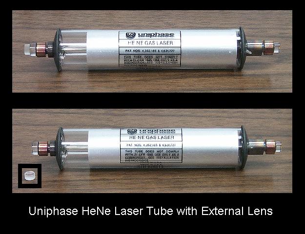
So, for an ideal HeNe laser with a .5 mm bore at 632.8 nm, the divergence angle will be about 1.6 mR. Note that although a wider bore should result in less divergence, this also permits more not quite parallel rays to participate in the lasing process. This assumes planar mirrors – which few HeNe lasers use. Where one or both mirrors are curved, the divergence changes. For example, it is common with HeNe tubes for the Output Coupler (OC) mirror to be ground slightly concave and for the High Reflector (HR) mirror to be planar. If the outer surface of the OC glass is not also curved to compensate for the negative lens that results, the beam will diverge at a much higher rate than would be expected for the bore diameter.HeNe laser tubes destined for barcode scanners often have a much higher divergence by design – up to 8 mR or more (where the optimal divergence may be as little as 1.7 mR or less). These tubes either have a negative curvature for the outer surface of the OC mirror glass (concave inward) or even an external negative lens attached with optical cement. See Uniphase HeNe Laser Tube with External Lens. The outer surface of OC in a normal HeNe tube will either be planar or slightly convex depending on whether the OC mirror is planar or slightly concave respectively. In the latter case, the convex surface precisely compensates for the extra divergence produced by the OC mirror curvature and results in a nearly optimally collimated beam. If the outer surface of your HeNe tube’s OC is concave, then it will have the high divergence characteristic. Note that the beam is still of very high quality but an additional positive lens approximately one focal length away from the OC will be required to produce a collimated beam.
Also see the section: Improving the Collimation of a HeNe Laser with a Beam Expander.
- Common HeNe lasers are of two types: random polarized and linearly polarized, which refers to the polarization of the output beam. A random polarized laser generally doesn’t produce anything like rapidly fluctuation polarization. It simply means that nothing has been done to control the polarization. And for the red (632.8 nm) wavelength, most HeNe will actually produce two sets of linearly polarized modes that are orthogonal to each other and fixed to the physical structure of the tube. These will change in amplitude as the tube heats up and the cavity expands.For a short tube (e.g., 5 or 6 inches), this is easily observed by placing a polarizer in the beam. At certain orientations, the beam brightness will then appear to go through cycles – light, dark, light, etc. However, polarization can be affected by external means. See the section: Unrandomizing the Polarization of a Randomly Polarized HeNe Tube.
- HeNe tubes which generate a linearly polarized beam are also available. Rotating a polarizer in a linearly polarized beam will result in high transmission at one orientation and close to zero transmission 90 degrees to it. These tubes usually include a glass plate oriented at the Brewster angle in the beam path (inside the resonator). This results in the optical resonator favoring one polarization orientation and the beam then becomes almost 100 percent linearly polarized. Melles Griot puts this plate inside next to the HR mirror of a HeNe tube that is otherwise similar to a random polarized model. Other manufacturers like Hughes have used a tube with a Brewster window at the OC-end and fasten the OC mirror to it externally. And, some really old cylindrical Hughes laser heads use tubes with Brewster windows at both ends with the mirrors mounted in the metal end-caps of the case. See the section: What is a Brewster Window? for more information.
- Lasers with external mirrors and Brewster windows (plates at the Brewster angle attached to the ends of the tube) will be linearly polarized and really expensive. They will also be more finicky as there may be some maintenance – the optics will need to be kept immaculate and the mirror alignment may need to be touched up occasionally. However, the fine adjustments will permit optimum performance to be maintained and changes in beam characteristics due to thermal effects should be reduced since the resonator optics are isolated from the plasma tube. Some HeNe lasers have an internal High Reflector (HR) mirror at one end of the tube but a Brewster window and external Output Coupler (OC) mirror at the other end. These are also linearly polarized and only half as finicky. 🙂
- In the trivial triviality department, the largest commercial two-Brewster laser I know of is the Spectra-Physics model 125, rated at 50 mW (red, 632.8 nm) but often producing much more output power when new. The plasma tube in this beast is over 5 feet long. Jodon also manufactures a 50 mW HeNe laser. The smallest two-Brewster plasma tube I’ve ever seen was from a photo in a book on lasers from the 1960s. It was only about 4 inches in length.
- Inexpensive internal mirror HeNe tubes nearly always operate with multiple longitudinal modes and most have a TEM00 beam profile (though some, designed for maximum power output in a given size package, may have a wider bore and operate with multiple transverse modes – TEMxy where ‘x’ and ‘y’ are integers greater than 0). See the section: Instant HeNe Laser Theory for more information on laser mode structure.
- High precision or lab quality HeNe lasers may be of quite unconventional construction incorporating plasma tubes that differ substantially compared to these mass produced HeNe tubes – both electronically and optically. Not only may one or both mirrors be mounted external to the tube in many of these, even if both mirrors are internal, there may be interesting and strange electrical, optical, electro-optical, or magnetic devices added to implement external modulation, mode locking, stabilization, and additional high performance (and high cost) features. Consider such a HeNe laser to be quite a find! See the sections: Spectra-Physics 120, 124, and 125 HeNe Laser Specifications and Interesting and Strange HeNe Lasers and for some examples.
Ghost Beams From HeNe Laser Tubes
If you project the output from some HeNe laser tubes (as well as other lasers) onto a white screen a meter or so away, you may see a main beam and a weak beam off to the side a few cm away from it. Maybe even another still weaker one after that.
Most internal mirror HeNe tubes should not have any higher order transverse (non-TEM00) modes. And, for multimode tubes, such modes should show up as part of, or adjacent to the main beam anyhow.
One possible cause for this artifact is that the output-end mirror (Output Coupler or OC) has some ‘wedge’ (the two surfaces are not quite parallel) built in to move any reflections – unavoidable even from Anti-Reflection (AR) coated optics – off to the side and out of harm’s way. Where wedge is present, the small portion of the light that returns from the outer AR coated surface of the OC will bounce back to the mirror itself and out again at a slight angle away from the main beam. In a dark room there may even be additional spots visible but each one will be progressively much much dimmer than its neighbor. Note that if the laser had a proper output aperture (hole), it would probably block the ghost beams and thus you wouldn’t even know of their existence!
Without wedge, these ghost beams would be co-linear with the main beam (exit in the same direction) and thus could not easily be removed or blocked. This could result in unpredictable interference effects since the ghost beams have an undetermined (and possibly varying) phase relationship with respect to the main beam. Sort of an unwanted built-in interferometer! The wedge also prevents unwanted reflections from that same AR coated front surface back into the resonator – perfectly aligned with the tube axis – which could result in lasing instability including cyclic variations in output power.
Thus, the ghost beam off to one side is likely a feature, not a problem! The effects of wedge on both the output beam and a beam reflected from a mirror with wedge is illustrated in Effects of Wedge on Ghost Beams and Normal Reflections. Note that his diagrams shows the effect of a beam coming in from the right and reflecting off the mirror. Where the beam is from the tube itself, the main beam corresponds to the one marked “1st Back Surface”.
If it isn’t obvious from close examination of the output mirror itself that the surfaces are not parallel, shine a reasonably well collimated laser beam (e.g., another HeNe laser or laser pointer) off of it at a slight angle onto a white screen. There will be a pair of reflected beams – a bright one from the inner mirror and a dim one from the outer surface. As above, if the separation of the resulting spots increases as the screen is moved away, wedge is confirmed (there may be higher order reflections as well but they will be VERY weak – see below). Where the mirror is curved, the patterns will be different but the wedge will still result in a line of spots at an angle dependent on the orientation of the tube.
Wedge is often present on the other mirror (High Reflector or HR) as well (in fact, this appears to be more likely than the OC). Wedge at the HR-end won’t affect the output beam at all but performing the reflectance test using a collimated laser (as above) at a near-normal angle of incidence may result in the following:
- An intense spot in the center due to the reflection of the beam from the actual mirror.
- A weaker spot on the thinner side of the optic due to the reflection of the beam from its front surface.
- Several progressively weaker spots on the thicker side of the optic due to multiple internal reflections between its front surface and the mirror.
With the exaggerated amount (angle) of wedge in Effects of Wedge on Ghost Beams and Normal Reflections, another effect becomes evident: The weaker spots are spaced further apart. It is left as an exercise for the student to determine what happens when a laser beam is reflected at an angle from such a mirror! Note that his diagrams shows the effect of a beam coming in from the right and reflecting off the mirror. Where the beam is from the tube itself, the main beam corresponds to the one marked “1st Back Surface”.
The appearance resembles that of a diffraction grating on such a beam (but for entirely different reasons). The behavior will be similar for an OC with wedge but because the HR mirror isn’t AR coated, the higher order spots (from the HR) are much more intense.
It is conceivable that slight misalignment of the mirrors may result in similar ghost beams but this is a less likely cause than the built-in wedge ‘feature’. However, if you won’t sleep at night until you are sure, try applying the very slightest force (a few ounces) to the mirror mounts (the metal, not the mirrors as they are very fragile) in each while the tube is powered (WARNING: High Voltage – Use a well insulated stick!!!!).
- If the ghost beam or beams are caused by wedge, all the spots will get weaker but their relative intensity and separation won’t change significantly. The peak absolute intensity should be in the relaxed position.
- If the cause is poor mirror alignment, the shape, position, relative intensity, and even the number of visible ghost beams may change dramatically. The intensity of the main beam may increase when the mirror is deflected certain ways further confirming that a realignment is needed.
Depending on the type of laser you have, see the sections: Checking and Correcting Mirror Alignment of Internal Mirror Laser Tubes, Quick Course in Large Frame HeNe Laser Mirror Alignment, and External Mirror Laser Cleaning and Alignment Techniques, for more information.
Another much simpler cause of an ugly beam from a HeNe (or other) laser is dirt on the outside of the output mirror since this will decrease the effectiveness of the AR coating. The dirt may also be on other external optics. Some HeNe laser heads have either a debris blocking glass plate glued at an angle to the end-cap or a neutral density filter to adjust output power. Even if AR coated, either of these may also introduce one or more ghost beams and if not perfectly clean, other scatter as well. I’m gotten supposedly bad HeNe lasers where the only problem was dirt on either the output mirror or external plate or filter.
(From: Steve Roberts.)
The mirror is wedged to cut down on the number of ghost beams, however even with a wedged mirror there is almost always one ghost. Nothing is wrong with your coatings on the mirror, it is simply a alignment matter. The mirrors need to be “walked” into the right position relative to the bore. There are many many paths down the bore that will lase, but only a few have the TEM00 beam and the most brightness, this generally corresponds to the one with minimum ghosts.
See the section: Quick Course in Large Frame HeNe Laser Mirror Alignment for more information.
Other Spectral Lines in HeNe Laser Output
While there is no such thing as a truly monochromatic source – laser or otherwise, the actual output beam of even an inexpensive HeNe laser is really quite good in this regard with a spectral line width of less than 1/500th of a nm. For a frequency stabilized HeNe laser, it can be 1,000 times narrower!
But if you look at the output of a HeNe laser with a spectrometer, there will be dozens of wavelengths present other than one around 632.8 nm (or whatever is appropriate for your laser if not a red one). Close to the output aperture, there will be a very obvious diffuse glow (blue-ish for the red laser) visible surrounding the actual beam. So why isn’t the HeNe laser monochromatic as expected?
With one exception, this is just due to the bore light – the spill from the discharge which makes it through the Output Coupler (OC) mirror. As your detector is moved farther from the output aperture, the glow spreads much faster than the actual laser beam and its intensity contribution relative to the actual beam goes down quickly. It is not coherent light but what would be present in any low pressure gas discharge tube filled with helium and neon. However, the presence of these lines can be confusing when they show up on a spectral printout.
The exception is that with a ‘hot’ (unusually high gain) tube or one with an OC that is not sufficiently narrow-band, one (though probably not more though not impossible) of the neighboring HeNe laser lines (e.g., for other color HeNe lasers) may be lasing though probably much more weakly than the primary line. For example, a red (632.8 nm) laser might also produce a small amount of output at 629.4 or 640.1 nm though this isn’t that common. For many applications, a bit of a “rogue” wavelength output is of little consequence and specifications for general purpose HeNe lasers usually don’t explicitly include any mention of them. However, rogue output will cause reduced accuracy in metrology applications and since they may not be TEM00, even where the beam is simply used for alignment.
I have a couple of 05-LHP-171 lasers that produce up to 10 percent of their output at 640.1 nm. The first is of unknown pedigree obtained in a lot laser junk from a well known laser surplus dealer. It may have been rejected for other reasons since the output at 632.8 nm is only about 4 mW when it should be well over 7 mW. The 632.8 nm is the normal TEM00 but the 640.1 nm beam may be TEM01 or TEM10 (2 modes) or even TEM11 (4 modes) depending on mirror alignment. With optimal mirror alignment for 632.8 nm, there may be no 640.1 nm at all. The other is a 25-LHP-171-249 system sold to a university lab. It has a manufacturing date of 2000, so this isn’t only a problem with old lasers as some people have claimed.
I have one ‘defective’ yellow (594.1 nm) HeNe tube that also produces a fair amount of orange (604.6 nm), and another that produces in addition some of the other orange line (611.9 nm).
While the probability of a commercial HeNe laser outputting at a rogue wavelength is low, where such a laser is used for measurements assuming pure 632.8 nm, errors could result. For more on this topic, see the paper:
- “Advice from the CCL on the use of unstabilized lasers as standards of wavelength: the helium-neon laser at 633 nm”, J. A. Stone, J. E. Decker, P. Gill, P Juncar, A Lewis, G. D. Rovera and M. Viliesid, 2009 Metrologia 46, 11-18.
In the course of research for this paper, the first author, Jack Stone, borrowed one of my interesting Melles Griot 633 nm lasers that produced 5 to 10 percent of its output at 640.1 nm! 🙂
And sometimes HeNe lasers are designed to produce more than one wavelength. PMS/REO used to produce such lasers, usually a visible and IR line, or a pair of IR lines. But one that I’ve acquired is a combination yellow (594.1 nm) and green (543.5 nm). Unlike many other PMS/REO lasers that produce multiple lines by accident :), this one was either designed that way or their Marketing department decided to convert a bug into a feature, since the laser head has a model number of LHGYR-0300M. Since these wavelengths are so far apart and are low gain, such an occurrence would normally not be likely, but I’ve also seen one where this was the case – a yellow laser that had a tiny bit of green.
I also have one that does orange (612 nm) and green (543.5 nm) but only under special conditions. It is a high mileage PMS/REO LHOR-0150M so it’s presumably supposed to be 612 nm only. But when run at lower than normal current, the green line pops up weakly. Just above the dropout current at 4.5 mA, it produces about 0.5 mW of orange and 0.05 nm of green. At 6.5 mA, it produces around 1 mW of pure 612 nm orange. I rather suspect this is a peculiarity of the tube running near end-of-life with a lower gas pressure. When new, it may not have been so interesting. 🙂
For more on multiline HeNes, see the sections starting with: The Dual Color Yellow/Orange HeNe Laser Tube. And to make your own (sort of), see the section: Getting Other Lasing Wavelengths from Internal Mirror HeNe Laser Tubes.
(From: Prof Harvey Rutt (h.rutt@ecs.soton.ac.uk).)
For gas lasers the plasma lines are typically 80 dB or more below the output (measured, of course, within the very small laser mode divergence). This is unlike most semiconductor lasers, which typically have broad ‘shoulders’ close in to the line, as well as ‘lines’ due to other modes and instabilities because the initial divergence of the diode is high, and spontaneous emission from the junction high, the broad background tends to be large.
For gas lasers it is usually in the form of narrow lines at remote wavelengths, very easily removed with an interference filter and/or spatial filtering in the *rare* cases where it matters. There is presumably a weak broad background from processes involving free electrons (bound/free and free/free), but I’ve never seen it even mentioned, let alone observed it. More likely to be significant in the high current density argon laser than the very low current density HeNe.
The only cases I have seen where the plasma lines caused problems were Raman measurements on scattering samples with photon counting detection, and weak fluorescence measurements which are similar.
In most cases scattered light in the monochromator is much more of an issue (hence double monochromators for Raman) and will obscure plasma lines in many cases.
Getting Other Lasing Wavelengths from Internal Mirror HeNe Laser Tubes
As a practical matter, the only wavelength that is useful from an internal mirror HeNe laser is the one for which it was designed. (Or the pair in the case of a couple of Research Electro-Optics (REO) lasers.) However, it is often possible to at least obtain unstable lasing at other wavelengths by extending the cavity using an external mirror. The output power of the other lines can be anywhere from almost non-existent to greater than the power at the original wavelength. This probably works best obtaining a some red from a long “hot” yellow (594.1 nm) or orange (611 nm) tube since at least one mirror is likely coated broadband to include yellow through red. Due to the low gain of the non-red lines, going the other way – getting yellow from a red tube, for example – is not likely to succeed unless the tube is very long. But obtaining lasing at other red wavelengths – and even orange – may be possible with a moderate size red HeNe laser tube. Even a 1 mW tube may give you 1 or 2 other red lines. I doubt it will work at all with a green HeNe tube having mirrors that appear orange in transmission since both mirrors are probably too transparent at even the yellow wavelength (except possibly if two external mirrors are used). However, if a mirror is more red in transmission, there might be a chance. See the section: Instant HeNe Laser Theory for a table of HeNe lasing wavelengths and relative gains.
I’ve gotten most of the well known HeNe lasing lines in this manner including up to 4 mW of red from a 2 mW yellow HeNe laser, both orange lines, various other red lines, and one of the wavelengths that isn’t even mentioned in most texts dealing with HeNe lasers. More below. I’ve only heard of one instance of any yellow being produced from non-yellow tubes, that being a REO 612 nm laser. And I haven’t even attempted to obtain green from non-green tubes.
Here’s how to get other wavelengths from your HeNe laser. Either a bare tube or complete laser head can be used for these experiments.
- Position an adjustable mount with a red OC or HR mirror a few inches beyond the OC or HR of the tube. Depending on the actual reflectance curves of the tube’s mirrors, one end will be better than the other. An HR may have a better chance of obtaining the low gain wavelengths if it is broadband, but many found on commercial HeNe lasers have been designed with high reflectivity only at the desired lasing wavelength in order to suppress the others. For the best chance of obtaining the most wavelengths from a red HeNe laser tube, I’d suggest an external red HR mirror beyond the tube’s internal OC mirror. For an “other color” tube, which end is best may be a random function (see below). However, in general, the OC is preferred over the HR since the outer surface almost always has better optical quality and will be AR coated. The outer surface of an HR may have some wedge and its shape and coating are pretty much irrelevant to normal laser operation (some are not even polished), so could be quite poor inside a cavity.The Radius of Curvature (RoC) of the external mirror may need to be consistent with a stable resonator configuration for the overall cavity. I’m not entirely sure this matters that much (and the implication in the next section is that it may not), but I’d still go with a stable configuration given a choice. If you don’t want to perform the calculations, a mirror that should work would be one from a dead red HeNe laser at least as long as the tube you are using. Of those I tried that worked at all, minimizing the distance between the ecternal mirror and tube resulted in the best results but this may not always be true. A dielectric mirror is definitely preferred but a good quality aluminized front surface (planar) mirror should work, though it may not be as good.
- Place diffraction gratings in the beams from both ends of the laser so the spectra can be projected onto white cards. If you don’t happen to own a “real” diffraction grating, a junk CD or CD-R disc works quite well as a reflection grating. In conjunction with a weak positive lens inserted in the beam before the grating (approximately 1 focal length from the end of the tube), the lines can be narrowed to permit sub-nm resolution. There will be a bit of spread perpendicular to the spectrum due to the bit patterns encoded on the disc but this just makes the lines look more like lines. :)The quality of the beam from the end of the tube opposite where your external mirror is located will probably be better, especially if the mirror is beyond the HR of the tube (which may have some wedge and is not AR coated). However, the beam from the external mirror end is instructive at least in helping to adjust the alignment.
- Power up the laser and carefully adjust the external mirror so that the beam from the tube (leakage from HR or output beam from OC) reflects back on itself. As the adjustments pass through this exact point, there should be evidence of wavelength competition as a color change and/or intensity change of the beams at one or both ends of the laser. The size of the beam exiting the external mirror will also be a minimum at this point and there may be visible interference effects. As the tube heats and expands, the wavelengths will come and go as the modes compete for attention. Just touching the mirror mount will also result in similar effects. Nothing will likely be stable for more than a few seconds. When lasing at the non-design wavelengths is present, the intensity of the original color(s) will probably decrease, possibly substantially.
Using my Melles Griot 05-LYR-170 yellow HeNe tube which for my “broken” sample, actually lases a combination of yellow (594.1 nm) and orange (604.6 nm) from both ends (see the section: The Dual Color Yellow/Orange HeNe Laser Tube), it was quite easy to achieve red output, and all three colors were occasionally present at the same time – an impressive achievement for a HeNe laser. My setup is shown in 05-LYR-170 HeNe Laser Tube Mounted in Test Fixture for Multiline Experiments. The output from the tube’s OC was directed at an AOL CD used as a reflective diffraction grating with the first-order beam projected on a white card several feet away. An MSN CD would work just as well 🙂 but a CD-R or CD-RW may not. The lens from a pair of eyeglasses (mildly positive, about 4 diopters or 1/4 meter focal length) narrowed the spots to improve spectral resolution. This rig could easily resolve lines separated by less than 1 nm. The first external “red” mirrors I tried were from an SP-084 HeNe laser tube but due probably to their relatively short RoC, the 05-LYR-170 had to be pushed quite close to the mount to get any red output. Mirrors designed for a longer laser worked better but there wasn’t much difference between the behavior using an HR or OC (99 percent).
Then to add to the excitement, with a bit of twiddling, I was able to obtain the other orange line (611.9 nm) as well, and at times, all 4 lines were lasing simultaneously! As expected, this additional line was only present when using an external HR. Depending on the original makeup of the yellow and orange beam (for this tube, their absolute and relative intensities varied with time and were also a very sensitive function of mirror alignment), it was possible to get mostly red or to vary the intensities of the other colors, most easily suppressing yellow in favor of orange and red. The intensity of the red output was never more than 1 mW or so. Its transverse mode structure varied from TEM00 to a star pattern with nothing in the center. Strange. Due to both surfaces of the HeNe tube’s HR mirror reflecting some of the intracavity beam resulting in a multiple cavity interference effect, there was a distinct lack of stability. To help compensate for this, a micrometer screw to precisely adjust cavity length without affecting mirror alignment would have been nice.
I also tried this with the external mirror mounted beyond the tube’s OC mirror but although there was a definite effect on yellow and orange lasing, it wasn’t possible to obtain any red output. (For the 05-LYR-170, the OC already reflects red quite well and the HR doesn’t.) Finally, I replaced the red external mirror with a green HR (from a tube of about the same length) mounted beyond the 05-LYR-170’s OC (since its HR by appearance looked like it might be a good mirror for green). But, not surprisingly, while this could affect the lasing of the yellow and orange lines, I could detect no coherent green photons. However, I would expect that with a appropriately coated mirrors (or possibly two such mirrors, one beyond each end of the tube), obtaining lasing at the relatively high gain 640.1 nm red line would be easy – the usual “red” mirrors may deliberately kill this line to prevent it from lasing. Although I couldn’t detect any evidence of lasing at the other red lines of 629.4 nm and 635.2 nm, these should also be possible with appropriate mirrors as they have higher gain than the yellow and oranges. Another interesting one would be the “Border Infra-Red” line at 730.5 nm. Lasing at the IR lines might also be possible but they are so boring. 🙂
Next, determined to do something with a more normal HeNe laser tube, I tried a Siemens tube but that refused to do anything interesting. Then, I tried a Melles Griot 05-LHR-150 which typically outputs a 5+ mW red (632.8 nm) beam. Since the OC for this laser is probably around 99% reflective at most, peaking at 632.8 nm, I figured that it would be best to place the external mirror beyond the OC rather than the HR. And, with the same external HR as used above, it was possible to obtain 6 lasing lines, count’m 6: 629.4 nm, 632.8 nm, 635.2 nm, 640.1 nm, a line popping up around 650 nm (all variations on red), ****AND**** 611.9 nm orange! However, since the output is being taken from the HR, none of the colors was more than a fraction of a mW.
Lasing of the 650 nm line was hard to obtain – it only showed up for a few seconds off-and-on every few minutes and increasingly rarely after the tube warmed up. The exact wavelength is very close to 650 nm (649.98 nm) as determined later with an Agilant 86140B Optical Spectrum Analyzer (OSA) which is a lot more expensive than my AOL CD. 🙂 (The wavelength was referenced to the 632.8 line from the same laser resulting in a measurement error bound of +/- 0.02 nm assuming the 632.8 nm line is actually 632.8 nm. But since this could also be slightly shifted, the error may be higher.) Getting anything at 650 nm is really puzzling as there are no HeNe lasing lines between 640.1 nm and 730.5 nm. But I have no doubt it is a true lasing line since it was fluctuating independantly of the others (later confirmed, see below). And all those other lines were quite accurately located corresponding to their handbook wavelengths in the diffracted pattern (and later confirmed with the OSA). So there is little reason to suspect that the funny one isn’t as well. When present, it appeared as strong (or weak) as all the expected ones, (except of course, the original 632.8 nm line which was usually, but not always, the strongest). If 650 nm is not a HeNe lasing line – it’s certainly not in the sequence of energy level transitions that produce all the other visible HeNe lines – one possible explanation is that there is some trace element present inside the tube and that is what’s lasing, not neon. I figured this to be a distinct possibility since the particular tube I am using originally had gas contamination and I revived it by heating the getter. (See the section: Repairing the Northern Lights Tube.) Therefore, the 650 nm wavelength may not be present with another more normal tube. But as it turned out, contamination has nothing to do with it.
I don’t think the 730.1 nm line was present but given its low relative perceived brightness, it may not have been visible at all using my AOL Special CD diffraction grating but I couldn’t find it with the OSA either. It took awhile to detect the evidence of the 635.2 nm line which only appeared sporatically (but it is the lowest gain of all the known ones above).
A few days later, I tried the same experiment with a couple of my old Spectra-Physics 084-1 HeNe laser tubes which are of soft-seal design so have almost certainly leaked over time (but still work fine). With my “hottest” SP084-1 (about 2.9 mW), I could almost duplicate the results of the 05-LHR-150 including the funny line around 650 nm but minus anything at 635.2 nm. Using a more normal 2.4 mW SP084-1, it was possible to obtain (non 632.8 nm) lines at 629.4 nm and 640.1 nm. For these, an SP084-1 HR worked almost as well for the external mirror as the longer RoC HR I had been using with the 05-LHR-150. I then installed a SP098-1, a common hard-seal barcode scanner tube (this sample puts out about 1.4 mW). With that, the only additional line was at 640.1 nm. Which particular lines appear in each case seem consistent with the length of the tubes (and thus the single pass gain) and the relative gain of the lasing lines.
Some quick calculations predict that the real effect of the external HR mirrors is the obvious one – to increase the circulating power. A 1 percent OC (typical) followed by even a 90 percent external mirror would result in greater than a 99.9 percent effective mirror for a range of wavelengths/modes. An external 99.9 percent HR would result in an even better effective mirror. It looks like the reflectance peak is relatively broad with respect to wavelength (the transmission peak is rather narrow). Specific modes for each of the wavelengths will be enhanced or suppressed. This would also appear to be consistent with the apparent lack of need for the external mirror to result in a stable resonator. All it has to do is form a Fabry-Perot cavity.
These have to be classified right up there in the really fascinating experiments department. Seeing any HeNe laser operating with multiple spectral lines is really neat.
For more examples of these stunts using an already interesting “defective” HeNe laser, see the sections starting with: Melles Griot Yellow Laser Head With Variable Output and in particular, the section: External Mirror Therapy for Variable Power 05-LYR-171 Yellow Laser Head.
As always, depending on mirror reflectivity and other factors, your mileage may vary. But feel free to try variations on these themes. The results from using an HeNe HR beyond the OC of almost any red HeNe laser tube should be easily replicated (except perhaps for the funny 650 nm line). Almost any mirror will do something since even an aluminized mirror will be returning over 90 percent of the otherwise wasted photons to the cavity – enough to boost the gain of all but the weakest lines enough for lasing if everything lines up just right. Aside from getting zapped by the high voltage or dropping the tube on the floor, they are low risk, high reward experiments.
And, can you believe that people get stuff like this published in scholarly journals? I was recently sent an article entitled: “Yellow HeNe going red: A one-minute optics demonstration” by Christopher Hopper and Andrzej Sieradzan, American Journal of Physics, vol. 76, pp. 596-598, June 2008. Geez, they could have saved a lot of time and effort and come here instead. Or, perhaps they did. 🙂
(From: Bob.)
For neutral neon at low pressure, the lines 640.3 nm, 659.9 nm are listed. For neutral helium, there is one at 667.8 nm. None of the other noble gases have wavelengths listed this short. As far as ionized species go, singly ionized argon has a line at 648.30 nm. Singly ionized krypton has a hand full of lines from 647 nm to 657 nm. Finally, xenon has one at 652 nm.
For atmospheric gases, there is a singly ionized nitrogen line at 648.3 nm. There are no neutral lines of interest for atmospheric gases. The footnotes for the above line were listed as CW lasing in 0.02 torr of krypton. Whats the standard operating pressure of a HeNe laser? Not THAT far out of the ball park I would guess.
(From: Sam.)
The last one sounds promising and would make sense given the history of the particular 05-LHR-150 and the soft-seal design of the SP084-1. Though HeNe lasers operate in the 2 to 3 TORR range – about 100 times higher pressure, the partial pressure of any N2 contamination could very well be down around 0.02 Torr.
However, I now know exactly where the 650 nm line is coming from and it has nothing whatsoever to do with contamination. The exciting writeup from someone who beat me to this by about 15 years follows in the next section preceeded by a condensed version, below.
I’ve also found a commercial laser that appears to produce a very stable 650 nm line. See the section: The PMS/REO External Resonator Particle Counter HeNe Laser.
(From: Stephen Swartz (sds@world.std.com).)
Lasing of certain HeNe tubes at 650 nm is a known phenomenon and not just a hallucination. The 650 nm line which is never discussed in most standard texts is not due to a “normal” transition of neon. It comes instead from a Raman transition. The 650 nm line is not often observed but when it is it will always be seen simultaneously with operation on a multitude of other lines. A large number of other “unusual” colors have been seen over the years. Higher power tubes with mirrors that are excessively broadband are your best bet for observing them. Often these lines flicker on and off over a few seconds to minutes time scale. A diffraction grating is a good way to look for them.
(From: Someone at a major laser company.)
The 650.0 nm Raman line is a known problem in that it competes for power with the 632.8 nm line intermittently, particularly in long tubes with high circulating power. Polarized tubes are much less susceptible to this effect and using a lower reflectance for the OC mirror helps since it reduces circulating power without affecting output very much (over a reasonable range).
Bruce’s Notes on Getting Other Lines from Red (633 nm) HeNe Laser Tubes
This, to make a gross understatement, would appear to be the definitive word on coaxing other colors from surplus HeNe laser tubes. And I thought six lines (including the mysterious 650 nm line) was an achievement. 🙂
(From: Bruce Tiemann (BruceT@ctilidar.com).)
I have gotten many lines from many different HeNe lasers. In my experience almost every tube is capable of giving at least one other line than 633 nm. (Most wavelengths have been rounded to save bits. So, 632.8 nm becomes 633 nm.) I have never tried doing this with lasers that give other lines than 633 nm, but since that line has the highest gain, it should be no mean feat to at least get that line from lasers that are supposed to not give it. It is also not my experience that calculations to ensure resonator stability, etc., are necessary. Just try it! My best results, in terms of output power, were with a flat grating as the external feedback mirror, and my best results in terms of new lines was obtained with a flat dielectric mirror, formerly used as a facet in a polygonal scanning assembly. Flat mirrors are not stable at any separation for a diverging beam, and HeNe lasers are very rare that give converging beams for their output.
The home stuff had the mirrors on blocks, with the steering accomplished by adjusting the HeNe tube by lifting one or the other end of the tube with sheets of paper, and the azimuth by moving the laser tube back and forth. The lab experiments were done with “real” mirror mounts, supplemented by a single PZT that tilted the feedback mirror a few microns.
(I like PZTs a great deal, and would like to observe that you can get PZT elements from little piezo alarms, from which the useful element can be extracted with some hand-tools and the mind-set of a 9-year-old kid dissecting a bug. 🙂 These are only about $1 each, as opposed to tens to hundreds of bucks for “real” PZTs that you buy from Thor, etc. One of them and a 0 to 50 VDC power supply can precision-wiggle a mirror on the micron scale, which is all that is needed for these experiments.)
(From: Sam.)
I have indeed done something similar using the piezo beeper from a dead digital watch to move a mirror in a HeNe laser based Michelson interferometer. With 0 to 25 V, it went through 4+ fringes which means over 2 full wavelengths at 633 nm. The configuration in these is called a “drum head” piezo element because the movement resembles that of a musical (depending on your point of view!) drum head with the most shift in the center. The piezo material itself doesn’t change by very much in thickness but is constructed so it distorts to produce the shape change. With care, the piezo material can be cut to size or drilled to pass light through its center. Much more voltage could have been safely applied if needed.
(From: Bruce.)
Something I also did is cast the spots from a smaller (approximately 3/4 m) spectrometer directly onto the CCD element of a small camera with no lens. I also fabricated a beam block by taping little wires to the side of a block, that would protrude up just in the locations of the very bright lines, like 633, 650, and 612 nm, to block them, but letting light of other colors pass in the ample space between the wires. You could still see when the bright lines were on from light leaking around the wires, but it wouldn’t wash out the image when they were.
In this case, when the feedback mirror was tilted, speckle, which was cast everywhere, would kind of shift around all over the place, but the new lines looked like ghostly bullseyes, which would breathe in and out as the mirror was tilted, but remain in the same location unlike the speckle. This was an easy way to see the weakest lines like 624 nm, and it was also how I discovered 668 nm, the CCD being more sensitive than the eye in the deep red. (I searched for but did not find the normal laser line 730 nm even with this very sensitive method.)
- “Normal” laser lines: The multiplet that gives 633 nm includes a total of nine lines, ranging from 543 nm at the green end to 730 nm at the far-red end. In between are yellow (594 nm), orange (605 and 612 nm), and several reds (629, 633, 635, and 640 nm). I have never obtained the yellow, green, or far-red line from any 633 laser but I have gotten all the others.
- Grating feedback: My best results are with a 5 mW Melles Griot 05-LHR-551 (or similar) laser. For maximum power output on these lines, a flat aluminum-coated grating, unblazed and with low (less than 10%) diffraction efficiency, gives near 1 mW power on 612 and 640 nm (as well as 650 nm, see below), when it is used to exactly retro-reflect the 633 nm beam back into the bore. The grating handily disperses the different colors off to the side. Sub-mW output power is also available on 629 and 635 nm. The beams sometimes wink on and off, but contrary to one’s impression they are on more often than they are off, and represent fairly stable and reliable outputs. I have also used a blazed 600 l/mm Edmund grating in Littrow, meaning, slanted so the first order is returned to the output coupler, and have thereby obtained operation at 612 and 640 nm, one at a time, at reduced output power, though of course with 633 nm on all the time.
- 640.1 nm: This line experiences anomalous dispersion from a nearby line, and therefore experiences gas lensing in the bore. Hence, it will oscillate in some marginally unstable (2-mirror) resonators even when 633 nm won’t. In a 3-mirror system, 2 from the laser tube and a third added by the experimenter, 640 nm is often the line that will oscillate with the least feedback. One of my 5 mW lasers will lase this line with an uncoated glass microscope slide, or even a plastic ruler or plastic box-lid as the third (feedback) mirror, up to a distance of several inches from the output coupler. With an uncoated Edmund 1/10 wave optical flat, 640 nm would oscillate with the surface located up to some 1.2 m away from the output coupler of the laser. That the resulting resonator is unstable can be clearly seen by the fact that the retro-reflected beam from the flat grossly overfills the size of the beam exiting the output coupler, nevertheless, 640 nm operation can be verified by looking at the diffracted beam from a grating, located behind the optical flat.That 640 nm line would lase even with a plastic ruler or similar non-mirror mirror and could be established by hand-holding the piece of plastic in the beam, braced against the laser tube.
- Dielectric feedback mirrors: Most small, 1 mW metal-ceramic tubes won’t give any other lines with a metal grating as the feedback element, so it is natural to try to coax them out with higher R. With use of a max-R dielectric mirror, almost every laser I have tried has given at least one other line. 640 nm is probably the most common next line to get, though there are some tubes that give many others but not that one, go figure. One small metal-ceramic tube would only give 629 and 635 nm, no others, even though these are weak lines. Probably has to do with the narrow-band coating on the back mirror. Interestingly, this laser would only give them periodically, with the 633 nm mode, normally TEM00, splitting up and becoming complicated, at which point the other lines would come on. When 633’s mode started to simplify, the others would vanish. One is drawn to think that the max-R mirror plus the laser output coupler forms a Fabry-Perot cavity, that when it becomes resonant at 633 nm, loses reflectivity there and thereby gives gain to the other lines, as well as inclines 633 to find a higher-order mode where the cavity is still reflective.
- 604.6 nm: My “best” tube gives 605 nm, only in one exact position of feedback mirror only a few mm from the output coupler,. and then, curiously, only when the feedback mirror is misaligned such that the appearance of the output, seen in transmission through the dielectric mirror, is a contiguous line of spots, instead of just the dot in the middle. This line competed strongly with 612, trading intensity and almost never being on at the same time. When 605 was on, it was just as bright as 612, which is curious given how reluctant it was to lase.
- 650.0 nm: Many 5 mw lasers give a line at 650.0 nm as well. This line isn’t a neon (Ne) transition, and isn’t due to an impurity either. Nor is it widely known. I demonstrated this line, and some of the usual other ones, to an astonished audience at Japan’s NIST, the National Research Laboratory for Metrology in Tsukuba, using one of their own “single line” HeNe lasers and one of their dielectric mirrors. It’s an electronic Raman line, pumped by 633 nm. The 2s states of Ne, which are what the 2p lower laser levels dump into, include two metastable states, from which it is forbidden to drop into the ground state. Hence, they build up population in the plasma. If a Ne metastable interacts with a 633 photon, it can take some of the energy to promote the atom to a higher state, and scatter the photon with the correspondingly lesser amount of energy, in this case at 650 nm. The energy difference between the 1S5 and 1S4 states, about 417 cm-1, is the same as the energy difference of the photons, 633 nm compared to 650 nm. This line was only discovered around 1985!The gain-bandwidth of the Raman transition is only 60 MHz wide, so the cavity modes for 633 nm must line up with the cavity modes at 650 nm, to within this uncertainty, in order for 650 nm to oscillate. Considering that the Doppler bandwidth is more like 1,500 MHz (1.5 GHz), and the FSR of the laser is ~hundreds of MHz, that is only rarely the case. Hence, 650 nm comes and goes, most of the time being gone. And when it’s gone, it’s gone. When the laser warms up, however, the cavity expands, and the 633 and 650 nm modes sort of vernier past each other, sometimes bringing them into alignment in difference-frequency space. When they align, 650 nm oscillates. The observed behavior is that 650 nm more rapidly blinks on when the laser is warming up, but only for short periods, and then as the tube comes closer to a steady-state temperature, the periods become less frequent, but 650 nm lasts for a longer duration each time. Eventually, at the steady-state condition, 650 nm will be gone, or more rarely, may persist. However, temperature control of the laser can cause 650 nm to become steady, in the low-tech way of putting a blanket made of paper sheets or something over the laser tube, to stabilize the laser tube temperature to the next-higher value that supports 650 nm oscillation, or in the higher-tech case with a heater tape and thermistor and temperature control unit. When 650 nm goes, it is strong, and one 5 mW tube gives nearly 1.5 mW of output power at 650 nm, when the feedback element was a metal grating, and the output was taken from the first order. It is also perceptibly a deeper red color than 633 or even 640 nm, to me.I (Sam) have tested two external PMS/REO particle counter assemblies lasing on up to 6 normal HeNe lines (605, 612, 629, 633, 635, 640) and the 650 nm Raman line where the 650 nm line was present 100 percent of the time with little variation in intensity. No stabilization of any kind is involved and the behavior is little changed from power-on to thermal equilibrium. This seems to directly contradict the need to simultaneous resonance mentioned above and in the papers. On one sample, I believe the 650 nm line was actually the strongest one, stronger even than the 633 line. On that laser, there was even the occasional hint of another strange line at around 653 nm. Also see the section: The PMS/REO External Resonator Particle Counter HeNe Laser.
- 4-wave mixing lines: Even less well known than 650 nm is that some HeNe lasers can give 4-wave mixing lines when 650 nm also oscillates. I have gotten 10 such lines from my “good” laser, many at one time. The most easily seen one is at 597 nm, and results from the addition of 417 cm-1 to a 612 nm photon. It can be thought of as a sideband of 612 nm, modulated by the 11.7 THz modulation set up by the difference frequency between 633 nm and 650 nm. Thus, to see 597 nm, one needs both 650 nm and also 612 nm to be oscillating. It also needs the feedback element to be a max-R dielectric mirror – the metal grating doesn’t work, even though it easily gives 612 nm and 650 nm at the same time. The 4-wave outputs, taken in transmission through the max-R feedback mirror, or through the high-R mirror on the back of the laser tube, are VERY weak, measured in 10s of nW at most, and dwindling down into the pW for the weakest ones. (This power level may be compared with the 40 nW that results from a 1 mW HeNe beam reflecting off a 4% reflector, an uncoated glass surface.) The stronger ones, such as 597 and 613 nm, can be easily as dots on white paper in a slightly darkened room, but the weakest ones, such as 589 and 624 nm, are best seen by looking directly into the grating, with dark-adapted eyes in a darkened room, in which case they look like star-disks that come and go as the feedback mirror is wiggled, differently from the 633 speckle. 597 nm is also perceptibly different color than even 612 nm. It looks “yellow” in comparison to the other orange and red spots from the HeNe, though the true color is more orange than that.These lines were best observed with the high-R feedback mirror located within about 6 inches of the output face of the laser, closer tending to be a bit better. Except for 589 nm, which required 605 nm to be oscillating, and this only occurred for one exact spacing of feedback mirror about 1.5 cm away from the output coupler, or about 1 mm away from the output flange of the tube, which I didn’t remove. (I did, however, find out that you can take a laser tube to the university infirmary, and ask to have it X-rayed, to determine the extent of the internal glass envelope within the aluminum outer casing, and they would only charge you $10 for the cost of the X-ray film and processing, which is not bad for a doctor visit including X-rays.)To my knowledge, these lines are my discovery.
A brief table shows the relationship between “pump” lines and 4-wave mixing lines, observed on one tube. Upper Sideband is toward shorter wavelengths from the pump; Lower Sideband is toward longer wavelengths of the pump (all values in nm):
   Upper       Pump       Lower
  Sideband  Wavelength  Sideband
 --------------------------------
   589.7       604.6      -----
   596.6       611.9      627.8
   613.3       629.4      646.4
   616.5       632.8     (650.0)
   618.8       635.2      652.5
   623.4       640.1      -----
  (633.8)      650.0      668.1
(632.8 and 650.0 nm are parenthesized since they are associated with the genesis of the 4-wave mixing lines.)
All in all this laser produced 17 different lines, many at one time, from a “single line” 633 swap-meet laser. 🙂
References:
The 650 nm discovery paper is:
- Assendrup, J.; Grover, B.; Hall, L.; Jabr, S., “CW Helium-Neon Raman Laser”, Applied Physics Letters; 1/13/86, vol. 48, is. 2, p86, January 1986.Abstract: Continuous lasing has been observed at 650 nm with a helium-neon electrical discharge placed in an ultrahigh finesse optical cavity. This new lasing line is attributed to a Stokes-Raman process between the 1s5 and 1s4 electronic states of neon atoms pumped by the 632.8-nm neon lasing line. A gain calculation based on a near-resonant stimulated electronic Raman process predicts a lasing threshold for the 650-nm line near that measured. Lasing output power was measured as a function of discharge current and helium-neon gas pressure for the pump line and for the Stokes line.
- Huang, Zhiwen; Zhao, Suitang; Jin, Haoran, “650 nm CW He-Ne Raman Laser”, (Chinese Journal of Lasers, vol. 15, Nov. 1988, p. 648-651), Chinese Physics – Lasers (ISSN 0887-3518), vol. 15, Nov. 1988, p. 803-806. Translation.Abstract: The 650 nm laser line of a simultaneously operating six-wavelength He-Ne laser was studied experimentally. It is shown that the precise lasing wavelength at 650 nm should be 650.00 + or – 0.05 nm and that this laser line is the result of the stimulated Raman scattering of the 632.8 nm transition between the 1S5 and 1S4 states. The characteristics of the Raman emission are studied and the gain is obtained.
- Peter Franke, Alfred Feitisch, Fritz Riehle, Kegung Zhao and Jurgen Helmcke, “Simultaneous cw laser emission including a Raman line of a He-Ne laser at six wavelengths in the visible range”, Applied Optics, vol. 28, no. 17, 1 September 1989, pp. 3702-3707.Abstract: Simultaneous CW laser emission has been observed in a He-Ne discharge at 611.8-, 629.3-, 632.8-, 635.1-, 640.1-, and 650.0-nm wavelengths. The output power and the mode spectra have been investigated for various operational conditions. Spontaneous mode locking of the different lines has been observed. The Raman transition (650.0 nm) pumped by the strong intracavity radiation at 632.8 nm has been investigated in detail and its relevance for a secondary multiwavelength standard is discussed.
Miscellaneous Comments on Getting Other Lines from HeNe Laser Tubes
(From: Flavio Spedalieri.)
I have a small Yellow Tube – 05-AYR-006 (as a combo with power supply 05-LPM-496-037). This tube is physically the same size at the 1mW reds, but has a larger bore resulting in multimode output.
I have managed to get the red (632.8nm) line to lase and perhaps orange lines by placing a HR from a 632.8nm HeNe at the HR end of the yellow tube.
Further, I obtained a broadband mirror from an Argon Laser tube, the OC worked best at the OC end of the Yellow tube, have got the laser to output green…
The mirrors hand-held – next to build a small external resonator assembly.
About the Waste Beam from a HeNe Laser
The so-called High Reflector (HR) or totally reflecting mirror in a HeNe laser isn’t really perfect, though the actual reflectivity is generally 99.95 percent or better. For a 1 mW laser tube with a 99 percent Output Coupler (OC) mirror, there is about 100 mW of intracavity power. Of this, about 50 uW will exit the rear through a 99.95 percent HR mirror. Unless the back of the HR mirror is painted or covered, there is always some small beam exiting the rear of the laser.
Normally, what comes out in that direction is, well, waste, and is of no consequence. But, there are times where it’s convenient to use this low power beam as a reference, expecting its power to track that of the main output beam. Unfortunately, it is sometimes not well behaved in this regard.
In constructing some amplitude stabilized HeNe lasers which depend on the waste beam feeding a photodiode for their feedback loop, an annoying characteristic of the waste beam has become evident with some otherwise perfectly normal and healthy HeNe laser tubes. Namely, that the relative power in the waste beam and the main beam does not remain constant as the tube warms up. In fact, one tube I was using had a variation of almost 2:1 in relative waste beam and output beam power depending on the tube’s temperature. This is probably due to one or both of the following:
- Variation in mirror reflectivity. Designing and manufacturing high reflectivity mirror coatings is somewhat of an art and they don’t always come out right. There may be ripples, a slope, or other variations in the reflectivity-versus-wavelength function. For an HR mirror on a 1 mW tube of, say, 99.97 percent resulting in 30 uW, a change of only 0.01 percent would add 10 uW to the waste beam.
- Lack of wedge or insufficient wedge between the inner and outer surfaces of the HR mirror. This will result in an etalon effect, effectively modulating the reflectance as a periodic function of temperature by perhaps 10 or 20 percent, which would appear as a similar change in the waste beam power. From room temperature to the operating temperature of a typical enclosed HeNe laser head, the power variation would go through several cycles.
The coating problem is more likely to result in a strictly increasing, or at least slow change in waste beam power with higher temperature while the etalon would be periodic with temperature going through several cycles, it might be possible to determine which of the two effects is present.
Normally, the waste beam is not used for anything and no one cares. Though there will also be a change in the power of the output beam (inversely relative to the waste beam) from these issues, it will be too small to be detectable without careful measurements, being swamped by the normal mode sweep power variations. But when the waste beam is used as the amplitude reference in a stabilized laser, the supposedly stabilized output will vary based on the relative waste beam power. That 10 uW change would result in the output power changing by 33 percent.
For some plots the mode sweep of normal and naughty tubes, see the section: Plots of HeNe Laser Power Output and Polarized Modes During Warmup. In particular, compare the plots of the Spectra-Physics 088 with those of the tubes that immediately follow it.


